US7610196B2 - Periodic signal enhancement system - Google Patents
Periodic signal enhancement systemDownload PDFInfo
- Publication number
- US7610196B2 US7610196B2US11/102,251US10225105AUS7610196B2US 7610196 B2US7610196 B2US 7610196B2US 10225105 AUS10225105 AUS 10225105AUS 7610196 B2US7610196 B2US 7610196B2
- Authority
- US
- United States
- Prior art keywords
- signal
- filter
- output
- enhancement system
- logic
- Prior art date
- Legal status (The legal status is an assumption and is not a legal conclusion. Google has not performed a legal analysis and makes no representation as to the accuracy of the status listed.)
- Active, expires
Links
Images


Classifications
- G—PHYSICS
- G10—MUSICAL INSTRUMENTS; ACOUSTICS
- G10L—SPEECH ANALYSIS TECHNIQUES OR SPEECH SYNTHESIS; SPEECH RECOGNITION; SPEECH OR VOICE PROCESSING TECHNIQUES; SPEECH OR AUDIO CODING OR DECODING
- G10L21/00—Speech or voice signal processing techniques to produce another audible or non-audible signal, e.g. visual or tactile, in order to modify its quality or its intelligibility
- G10L21/02—Speech enhancement, e.g. noise reduction or echo cancellation
- G10L21/0316—Speech enhancement, e.g. noise reduction or echo cancellation by changing the amplitude
- G10L21/0364—Speech enhancement, e.g. noise reduction or echo cancellation by changing the amplitude for improving intelligibility
- G—PHYSICS
- G10—MUSICAL INSTRUMENTS; ACOUSTICS
- G10L—SPEECH ANALYSIS TECHNIQUES OR SPEECH SYNTHESIS; SPEECH RECOGNITION; SPEECH OR VOICE PROCESSING TECHNIQUES; SPEECH OR AUDIO CODING OR DECODING
- G10L25/00—Speech or voice analysis techniques not restricted to a single one of groups G10L15/00 - G10L21/00
- G10L25/90—Pitch determination of speech signals
Definitions
- This inventionrelates to signal processing systems, and more particularly to a system that may enhance periodic signal components.
- Audio signal processing systemssupport many roles. Audio signal processing systems clearly and cleanly capture sound, reproduce sound, and convey sound to other devices. However, audio systems are susceptible to noise sources that can corrupt, mask, or otherwise detrimentally affect signal content.
- Wind, rain, background noise such as engine noise, electromagnetic interference, and other noise sourcesmay contribute noise to a signal captured, reproduced, or conveyed to other systems.
- noise level of soundincreases, intelligibility decreases.
- This inventionprovides a signal enhancement system that may reinforce signal content and may improve SNR in a signal.
- the systemdetects, tracks, and reinforces non-stationary periodic signal components in the signal.
- the periodic signal componentsmay represent vowel sounds or other voiced sounds.
- the systemalso may detect, track, and attenuate quasi-stationary signal components in the signal.
- the enhancement systemincludes a signal input, delay logic, a partitioned adaptive filter, and signal reinforcement logic.
- the partitioned adaptive filtermay track non-stationary fundamental frequency components in the input signal based on a delayed version of the input signal.
- the partitioned adaptive filteroutputs multiple filtered signals.
- the filtered signalsmay approximately track and enhance frequency content in the input signal.
- the reinforcement logiccombines the input signal and the filtered signals to produce an enhanced signal.
- a second adaptive filtermay be employed to track and suppress quasi-stationary signal components in the input signal.
- FIG. 1is a signal enhancement system with preprocessing and post processing logic.
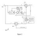
- FIG. 2is a single stage signal enhancement system.
- FIG. 3is a plot of filter coefficients in a filter adapted to a female voice.
- FIG. 4is a plot of filter coefficients in a filter adapted to a male voice.
- FIG. 5is a flow diagram of signal enhancement.
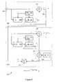
- FIG. 6is a multiple stage signal enhancement system.
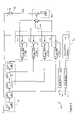
- FIG. 7is a signal enhancement system including a partitioned adaptive filter.
- FIG. 8is an alternative implementation of a signal enhancement system including a partitioned adaptive filter.
- FIG. 9is a comparison of frequency performance of signal enhancement systems shown in FIGS. 2 and 8 .
- FIG. 10is a comparison of frequency performance of signal enhancement systems shown in FIGS. 7 and 8 .
- FIG. 11is a flow diagram of signal enhancement.
- FIG. 12are multiple stage signal enhancement systems.
- the enhancement systemdetects and tracks one or more fundamental frequency components in a signal.
- the signal enhancement systemreinforces the tracked frequency components.
- the enhancement systemmay improve the intelligibility of information in a speech signal or other audio signals.
- the reinforced signalmay have an improved signal-to-noise ratio (SNR).
- a signal enhancement system 100may operate in conjunction with preprocessing logic 102 and post-processing logic 104 .
- the enhancement system 100may be implemented in hardware and/or software.
- the enhancement system 100may include a digital signal processor (DSP).
- the DSPmay execute instructions that delay an input signal, track frequency components of a signal, filter a signal and/or reinforce spectral content in a signal.
- the enhancement system 100may include discrete logic or circuitry, a mix of discrete logic and a processor, or may be distributed over multiple processors or programs.
- the enhancement system 100may accept input from the input sources 106 .
- the input sources 106may include digital signal sources or analog signal sources such as a microphone 108 .
- the microphone 108may be connected to the enhancement system 100 through a sampling system 110 .
- the sampling system 110may convert analog signals sensed by the microphone 108 into digital form at a selected sampling rate.
- the sampling ratemay be selected to capture any desired frequency content.
- the sampling ratemay be approximately 8 kHz to about 22 kHz.
- the sampling ratemay be approximately 22 to about 44 kHz.
- Other sampling ratesmay be used for speech and/or music.
- the digital signal sourcesmay include a communication interface 112 , other circuitry or logic in the system in which the enhancement system 100 is implemented, or other signal sources.
- the enhancement system 100may accept the digital signal samples with or without additional pre-processing.
- the signal enhancement system 100may also connect to post-processing logic 104 .
- the post-processing logic 104may include an audio reproduction system 114 , digital and/or analog data transmission systems 116 , or video processing logic 118 . Other post-processing logic also may be used.
- the audio reproduction system 114may include digital to analog converters, filters, amplifiers, and other circuitry or logic.
- the audio reproduction system 114may be a speech and/or music reproduction system.
- the audio reproduction system 114may be implemented in a cellular phone, car phone, digital media player/recorder, radio, stereo, portable gaming device, or other devices employing sound reproduction.
- the video processing system 118may include circuitry and/or logic that provides a visual output.
- the signal used to prepare the visual outputmay be enhanced by the processing performed by the enhancement system 100 .
- the video processing system 118may control a television or other entertainment device. Alternatively, the video processing system 118 may control a computer monitor or liquid crystal display (LCD).
- LCDliquid crystal display
- the transmission system 116may provide a network connection, digital or analog transmitter, or other transmission circuitry and/or logic.
- the transmission system 116may communicate enhanced signals generated by the enhancement system 100 to other devices.
- the transmission system 116may communicate enhanced signals from the car phone to a base station or other receiver through a wireless connection such as a ZigBee, Mobile-Fi, Ultrawideband, Wi-fi, or a WiMax network.
- FIG. 2illustrates the enhancement system 100 .
- the enhancement system 100includes a signal input 202 .
- the signal input 202carries an input signal that will be processed by the enhancement system 100 .
- the input signalis labeled “x”.
- the input signalmay be time domain samples of speech.
- speech signalsare discussed below.
- the enhancement system 100may enhance signals with any other range of frequency content, whether audible or inaudible.
- the enhancement system 100may process quasi-stationary or non-stationary signals.
- Non-stationary signalsmay vary in their frequency and/or amplitude content relatively quickly over time.
- Voiceis one example of a non-stationary signal.
- the fundamental frequency component in a speaker's voicechanges during speech.
- the change in fundamental frequencymay vary by as much as approximately 50 percent per 100 ms or more.
- the speaker's voicemay have a relatively constant pitch.
- Quasi-stationary signalschange in frequency and/or amplitude less frequently than non-stationary signals.
- Quasi-stationary signalsmay arise from machine noise, a controlled human voice, or from other sources. Slowly changing engine noise or alternator whine are examples of quasi-stationary signals.
- the input signalis coupled to delay logic 204 .
- the delay logic 204imparts a delay to the input signal.
- the delaymay vary widely depending on the particular implementation of the enhancement system 100 .
- the delaymay correspond to a period of a selected maximum pitch.
- the maximum pitchmay be equal to the greatest pitch in the input signal that the enhancement system 100 enhances.
- the maximum pitchmay vary widely depending on the type and characteristics of the input signal.
- Speech signalsmay include a fundamental frequency component from approximately 70 Hz to about 400 Hz.
- Male speechoften includes a fundamental frequency component between approximately 70 Hz to about 200 Hz.
- Female speechoften includes a fundamental frequency component between approximately 200 Hz to about 400 Hz.
- a child's speechoften includes a fundamental frequency component between approximately 250 Hz to about 400 Hz.
- the enhancement system 100may process input signals that include speech from both male and female voices, either separately or simultaneously and overlapping.
- the maximum pitch periodmay approximately correspond to the period of the fundamental frequency of the female voice.
- the maximum pitch periodmay be approximately about 1/300 Hz (approximately 3.3 ms), or may be another pitch period associated with female voice.
- the enhancement system 100may processes speech only from males.
- the maximum pitch periodmay correspond to the period of the fundamental frequency of male voice.
- the maximum pitch periodmay be approximately 1/150 Hz (approximately 6.6 ms), or may be another pitch period.
- the delay logic 204may delay the input signal by the number of signal samples corresponding to the maximum pitch period.
- the delayed input signalmay be received by the filter 206 .
- the filter 206includes a filter output 208 that carries a filtered output signal, labeled ‘y’ in FIG. 2 .
- the filter 206may track one or more frequency components in the input signal based on the delayed input signal.
- the filter 206may track the fundamental frequencies in the input signal as the pitch changes during voiced speech.
- the filter 206may reproduce, replicate, approximate or otherwise include the tracked frequency content in the filtered output signal.
- the filter 206may be a Finite Impulse Response Filter (FIR) or other type of digital filter.
- the coefficients of filter 206may be adaptive.
- the filter 206may be adapted by a Normalized Least Mean Squares (NLMS) technique or other type of adaptive filtering technique such as Recursive Least Squares (RLS) or Proportional LMS.
- NLMSNormalized Least Mean Squares
- RLSRecursive Least Squares
- Proportional LMSProportional LMS
- the filter 206may converge to the fundamental frequency in the input signal.
- the range of fundamental frequencies f 0 over which the filter 206 convergesmay be given by:
- ⁇ F0MAXis the period for the maximum pitch (expressed in terms of samples)
- f sis the sampling frequency (in units of Hz)
- Lis the length of the filter 206 (in units of samples).
- the filter length Lmay increase or decrease to increase or decrease the frequency extent over which the filter 206 tracks frequency components.
- the maximum pitchwas approximately 300 Hz and the delay logic 204 implemented a 27 sample delay.
- a filter length L of 64 samplesyields a filter 206 that tracks fundamental frequency content over a frequency range of approximately 88 Hz to about 296 Hz:
- the filter 206may adapt over time.
- the filter 206may quickly adapt by evaluating an error signal ‘e’ on a sample-by-sample basis.
- the filter 206may adapt based on blocks of samples, or other another basis.
- the filter 206may change one or more of its filter coefficients.
- the filter coefficientsmay change the response of the filter 206 .
- the filter coefficientsmay adapt the filter 206 so that the filter 206 attempts to minimize the error signal ‘e’.
- the error estimator 210may generate the error signal ‘e’.
- the error estimator 210may be an adder, comparator, or other circuitry or logic.
- the error estimator 210may compare the input signal ‘x’ with the filtered output signal ‘y’.
- the filter 206converges to the fundamental frequency in the input signal, the error signal decreases. As the error signal decreases, the filtered output signal ‘y’ more closely resembles the input signal ‘x’ delayed by an integer multiple of the signal's fundamental frequencies.
- the gain control logic 212may respond to the error signal.
- the optional gain control logic 212may include a multiplier 214 and a gain parameter 216 .
- the gain control logic 212may attenuate, amplify, or otherwise modify the filtered output signal.
- FIG. 2shows that the gain control logic 212 applies a gain, ‘A’, to the filtered output signal to produce the gain controlled signal ‘Ay’.
- the reinforcement logic 218may reinforce frequency content in the input signal ‘x’ with the gain controlled signal ‘Ay’.
- the reinforcement logic 218may be an adder or other circuitry and/or logic.
- the gain control logic 212may reduce the gain, ‘A’.
- the filtered output signalmay contribute less to the enhanced output signal.
- the relationship between the error signal and the gainmay be continuous, stepped, linear, or non-linear.
- the enhancement system 100establishes one or more error thresholds. As the error signal exceeds an upper threshold, the gain control logic 212 may reduce the gain ‘A’ to 0 (zero). The upper threshold may be set to the input signal so that if e>x, then the gain ‘A’ may be set to zero. As the error signal falls below a lower threshold, the gain control logic 212 may increase the gain ‘A’ to 1 (one).
- the filter control logic 220may reset the filter 206 .
- the control logic 220may zero-out the filter coefficients, re-initialize the filter coefficients, or may take other actions.
- the control logic 220may also dynamically modify the filter length, may modify the delay implemented by the delay logic 204 , or may modify other characteristics of the enhancement system 100 .
- the control logic 220also may modify the enhancement system 100 to adapt to changing environments in which the enhancement system 100 is used, to adapt the enhancement system 100 to a new speaker, or other applications.
- the filter control logic 220also may control how quickly the filter 206 adapts, whether the filter adapts, or may monitor or control other filter characteristics. In the context of a system that enhances non-stationary signals, the control logic 220 may expect quickly changing frequency and amplitude components in the input signal. The control logic 220 may also expect or determine over time that particular frequency components in the input signal are prevalent.
- the control logic 220also may determine that the input signal has changed in frequency content, amplitude, or other characteristics from what is expected or from what has been determined. In response, the control logic 220 may stop the filter 206 from attempting to adapt to the new signal content, may slow the rate of adaptation, or may take other actions. The control logic 220 may exercise control over the filter 206 until the input signal characteristics return to what is expected, until a predetermined time has elapse, until instructed to release control, or until another time or condition is met.
- the delay logic 204prevents the filtered output signal from precisely duplicating the current input signal ‘x’.
- the filtered output signalmay closely track the selected periodicities in the input signal ‘x’.
- periodic signal componentsmay combine constructively and random noise components may combine destructively. Therefore, the periodic signal components may be enhanced more than the noise.
- the delay introduced by the delay logic 204 and the filter 206may be approximately one cycle of a fundamental frequency component tracked by the filter 206 .
- the delaymay correspond to the glottal pulse delay for voice sounds, such as vowels.
- the delaymay allow the fundamental frequency components to add in-phase or approximately in-phase.
- the resulting gain in the fundamental frequency content in the enhanced output signalmay be approximately 6 dB or more.
- the noise in the input signal and the filtered output signaltends to be out of phase.
- the noisemay increase less than the enhanced frequency content, for example by 3 dB or less.
- the enhanced output signalmay have increased SNR.
- the input signal that the enhancement system 100 processesmay include multiple fundamental frequencies. For example, when two speakers are speaking at the same time, the input signal may include two non-stationary fundamental frequencies. When multiple fundamental frequencies are present, the filter 206 continues to adapt and converge to provide a filtered out signal ‘y’ that is a delayed version of the input signal.
- the reinforcement logic 218may reinforce one or more of the fundamental frequencies present in the input signal.
- a plotillustrates coefficients 300 for the filter 206 .
- the coefficientsare plotted by coefficient number on the horizontal axis and magnitude on the vertical axis.
- the coefficients 300show the filter 206 as it has adapted to female speech.
- the coefficients 300may be analyzed to determine a fast estimate of the fundamental frequencies in the input signal with good temporal resolution.
- the coefficients 300begin to peak around coefficient 304 (the fifth filter coefficient), coefficient 306 (the sixth filter coefficient), and coefficient 308 (the seventh filter coefficient).
- coefficient 304the fifth filter coefficient
- coefficient 306the sixth filter coefficient
- coefficient 308the seventh filter coefficient
- the coefficient peakis at the sixth filter coefficient 306 . Assuming an 8 kHz sampling rate and a 27 sample delay:
- a plotshows coefficients 400 for the filter 206 as it has adapted to male speech.
- the coefficient peakappears near coefficient 402 (the 34th filter coefficient), coefficient 404 (the 35th filter coefficient), and coefficient 406 (the 36th filter coefficient).
- An approximation to the fundamental frequencyis:
- the control logic 220may store historical data on many characteristics of the input signal, including the fundamental frequency of the input signal as it changes over time.
- the control logic 220may examine the historical data as an aid in determining whether the characteristics of the input signal have unexpectedly changed.
- the control logic 220may respond by exercising adaptation control over the filter 206 or by taking other actions.
- FIG. 5shows a flow diagram 500 of acts that may be taken to enhance a periodic signal.
- a maximum pitchis selected for processing by the enhancement system 100 (Act 502 ).
- the delay logic 204may be set to implement the period of the maximum pitch (Act 504 ).
- a frequency range over which the enhancement system 100 will operatemay also be selected (Act 506 ).
- the filter length of the filter 206may be set to accommodate the frequency range (Act 508 ).
- the filter lengthmay be dynamically changed during filter 206 operation.
- the input signalis delayed and filtered (Act 510 ).
- the enhancement system 100may generate an error signal and responsively adapt the filter 206 (Act 512 ).
- the enhancement system 100may control the gain of the filtered output signal (Act 514 ).
- the enhancement system 100may add the input signal and the gain controlled signal (Act 516 ). An enhanced output signal may result.
- the enhancement system 100also may determine fundamental frequency estimates (Act 518 ).
- the enhancement system 100may employ the frequency estimates to exercise adaptation control over the filter 206 (Act 520 ).
- FIG. 6shows a multiple stage enhancement system 600 .
- the enhancement system 600includes a first filter stage 602 and a second filter stage 604 .
- the filter stages 602 and 604may respond or adapt at different rates.
- the first filter stage 602may adapt slowly and may suppress quasi-stationary signal components.
- the quasi-stationary signal componentsmay be present in the input signal because of relatively consistent background noise, such as engine noise or environmental effects, or for other reasons.
- a signal input 606connects to the first stage 602 .
- the signal input 606may connect to the delay logic 608 .
- the delay logicmay implement a delay that corresponds to the period of a maximum quasi-stationary frequency that may be suppressed by the first stage 602 .
- the maximum quasi-stationary frequencymay be selected according to known or expected characteristics of the environment in which the enhancement system 600 is used.
- the filter control logic 610may dynamically modify the delay to adapt the first stage 602 to the environment.
- the filter control logic 610also may control the quasi-stationary filter 612 .
- the filter 612 in the first stagemay include signal component tracking logic such as a NLMS adapted FIR filter or RLS adapted FIR filter.
- the filter 612 in the first stagemay adapt slowly, for example with a sampling rate of 8 kHz and a filter length of 64 an NLMS step size larger than 0 and less than approximately 0.01 may allow attenuation of quasi-stationary periodic signals while minimally degrading typical speech signals.
- the first stage filtered output 614may provide a filtered output signal that approximately reproduces the quasi-stationary signal component in the input signal.
- the suppression logic 616 and slow filter adaptationmay allow non-stationary signal components to pass through the first stage 602 to the second stage 604 .
- the suppression logic 616may suppress quasi-stationary signal components in the input signal.
- the suppression logic 616may be implemented as arithmetic logic that subtracts the filtered output signal from the input signal.
- the replicated quasi-stationary signal content in the filtered output signalis removed from the input signal.
- ‘e 1 ’is the first stage output signal
- ‘x’is the input signal
- ‘y 1 ’is the first stage filtered output.
- the first stage output 618may be connected to the second stage 604 .
- the second stage 604may process the signal ‘x 2 ’ with the adaptive filter 206 .
- the filter 206may adapt quickly, for example with a sampling rate of 8 kHz and a filter length of 64 an NLMS step size larger than approximately 0.6 and less than 1.0 may allow the adaptive filter 206 to track the fundamental frequencies in typical speech signals.
- the second stage 604may enhance non-stationary signal components in the first stage output signal.
- the non-stationary signal componentsmay be present in the input signal as a result of speech, music, or other signal sources.
- the second stage 604may process the first stage output signal as described above.
- the enhancement system 600employs a first suppression stage 602 followed by a second enhancement stage 604 .
- the enhancement system 600may be employed to reinforce non-stationary signal content, such as voice content.
- the enhancement system 600may remove or suppress the slowly changing signal components.
- the first stage 602may remove or suppress engine noise, road noise, or other noises, while the second stage 604 enhances non-stationary signal components, such as male or female voice components.
- the signal enhancement system 100may enhance periodic signal content, increase SNR, and/or decrease noise in an input signal. When applied to a voice signal, the enhancement system 100 may reinforce fundamental speech frequencies and may strengthen vowel or other sounds. The enhancement system 100 may enhance other signals, whether they are audible or inaudible.
- the overall delay introduced by the delay logic 204 or 608 and the filter 206 or 612also may be approximately an integer number (one or greater) of cycles of the tracked pitch period. Delaying by additional cycles may allow the input signal to change to a greater degree than waiting one cycle. Adding the longer delayed filtered signal to the current input signal may produce special effects in the output signal such as reverberation, while still enhancing fundamental frequency components.
- a signal enhancement system 700includes a partitioned adaptive filter 702 as well as partitioned delay logic 704 .
- the partitioned adaptive filter 702includes multiple adaptive filters, illustrated in FIG. 7 as adaptive filters 1 through ‘i’.
- the adaptive filters 1 , 2 , 3 , and ‘i’are labeled 706 , 708 , 710 , and 712 , respectively.
- the output of each adaptive filtermay connect to gain logic 746 including multipliers that apply fixed or variable gain parameters to the filter outputs.
- FIG. 7illustrates gain parameters 714 , 716 , 718 , and 720 individually applied to the outputs of the filters 706 - 712 .
- the gain and filter control logic 722may exercise control over the gain parameters 714 - 720 and filter adaptation for each individual filter 706 - 712 .
- the reinforcement logic 724may be added together by the reinforcement logic 724 to obtain a weighted sum of the filter outputs, ‘y SUM ’.
- the reinforcement logic 726adds the weighted summed filter outputs ‘y SUM ’ to the input signal ‘x’ to create the output signal ‘s’.
- the reinforcement logicmay be an adder or other signal summer.
- the partitioned delay logic 704includes multiple series-connected delay blocks, five of which are labeled as delay blocks 728 , 730 , 732 , 734 , and 736 .
- the partitioned filter 702divides the entire signal tracking task across multiple adaptive filters 706 - 712 .
- Each adaptive filter 706 - 712may process and adapt a portion of the overall impulse response of the partitioned filter 702 .
- each adaptive filter 706 - 712may have a smaller length (e.g., a smaller number of taps) than the longer adaptive filter shown in FIG. 2 .
- each adaptive filtermay process 20 (or any other number) taps of the overall impulse response.
- the number of adaptive filter partitions in the filter 702is equal to the length of the overall impulse response, and therefore each adaptive filter has length 1.
- the overall length of the partitioned filter 702may be chosen as explained above with respect to the range of frequencies that the partitioned filter 702 will track.
- the adaptive filters 706 - 712may vary in length depending on the expected fundamental frequencies in an input signal. For processing the portion of the impulse response at or around the expected fundamental frequency, the adaptive filters 706 - 712 may be partitioned into shorter, more quickly adapting filters. Away from the expected fundamental frequency, the adaptive filters 706 - 712 may be longer more slowly adapting filters. Thus, the lengths of the adaptive filters 706 - 712 may be selected to provide fast adaptation at or around frequencies of interest in the input signal.
- Each adaptive filter 706 - 712individually uses fewer filter coefficient updates.
- the adaptive filter 706 - 712may update more quickly than filters in an implementation employing longer adaptive filters.
- Faster filter updatesyield enhanced overall tracking performance, particularly at higher frequencies.
- the increase in overall tracking performancelends itself to tracking fundamental frequencies that change quickly, whether those frequencies are voiced or are artificially created.
- a least-mean-square (LMS) algorithm, a recursive-least-square (RLS) algorithm, variants of the LMS RLS, or other techniquesmay be employed to update the filter coefficients based on the individual error signals ‘e i ’.
- the delay logic 704delays the arrival of the input signal ‘x’ to one or more of the filters 706 - 712 .
- FIG. 7shows that each filter 706 - 712 is associated with its own delay.
- Each delay block 728 - 736may implement a delay of any number of signal samples.
- Each subsequent delay logic 730 - 736has an individually configurable delay, shown in FIG. 7 as delays of M 1 , M 2 , M 3 , and Mi samples.
- the delay block 730feeds the first adaptive filter 706
- the delay block 732feeds the second adaptive filter 708
- the third delay block 734feeds the third adaptive filter 710 , and so on up to the i th delay block 736 that feeds the i th filter 712 .
- the delays D, M 1 , . . . , Mimay each be the same or may each be different.
- the delays M 1 , . . . , Mimay correspond to the length (e.g., the number of taps) of the adaptive filter which the delay block feeds, or may be different from the length of the adaptive filter which the delay block feeds.
- the length of the adaptive filter 710may be M 3 taps and the delay block 734 that feeds the adaptive filter 706 may delay signal samples by M 3 samples.
- the adaptive filterWhen the length of an adaptive filter ‘i’ is less than its associated delay Mi, the adaptive filter may initially converge faster. When the length of an adaptive filter ‘i’ is greater than its associated delay Mi, the adaptive filter may experience a smaller mean squared error upon convergence.
- the filter lengths and/or delay logic 730 - 736may be set according to the implementation guidelines for the implementation in which the system 700 is employed.
- the delay Dmay be chosen to set a range of fundamental frequencies over which the system 700 will adapt.
- the range of fundamental frequencies f 0 or pitches over which the filter 700 converges or adaptsis given by:
- the gain and filter control logic 722may exercise control over the gains 714 - 720 and filter adaptation on an individual basis, i.e., for each individual filter 706 - 712 .
- the control techniques described above with respect to the filter control 220may also be employed in the signal enhancement system 700 .
- the gains 714 - 720may be proportional to, or may be otherwise set based on the signal to noise ratio of the input signal ‘x’. As SNR decreases, one or more of the gains 714 - 720 may increase in an attempt to suppress the noise. As SNR increases, one or more of the gains 714 - 720 may decrease or may be set to zero.
- the gains 714 - 720may be determined as a function of the filter coefficients of its corresponding adaptive filter, or in other ways.
- ⁇ (h i )is a function of the adaptive filter coefficients and may be defined in many ways depending on the enhancement desired. Examples of ⁇ (h i ) are given below:
- f ⁇ ( h i )max n ⁇ ⁇ h i ⁇ ( n ) ⁇ ( 1 )
- f ⁇ ( h i )max n ⁇ ⁇ h i ⁇ ( n ) ⁇ 2 ( 2 )
- f ⁇ ( h i )⁇ n ⁇ ⁇ h i ⁇ ( n ) + ⁇ n ⁇ ⁇ ⁇ h i ⁇ ( n ) ⁇ 2 ( 3 )
- f ⁇ ( h i )max n ⁇ ⁇ h i ⁇ ( n ) ⁇ + max n ⁇ h i ⁇ ( n ) 2 ( 4 )
- f ⁇ ( h i )[ max n ⁇ ⁇ h i ⁇ ( n ) ⁇ + max n ⁇ h i ⁇ ( n ) 2 ] m , m > 0 ( 5
- the gains 714 - 720may be selected or determined based on other information in addition to or as an alternative to the filter coefficients.
- the gains 714 - 720may be selected or modified (e.g., increased) to amplify the effect of an adaptive filter with coefficients that will enhance or strengthen periodic components of the input signal.
- the gains 714 - 720may also be selected or modified (e.g., reduced or set to zero) to reduce or eliminate the effect of an adaptive filter with coefficients (generally negative coefficients) that would degrade or weaken periodic components of the input signal.
- the gains 714 - 720may be set in other ways that depend on the magnitude of the filter coefficients, however. Accordingly, the enhancement system 700 may set the gains 714 - 720 on an individual basis such that only enhancement occurs in the system 700 .
- FIG. 8shows an enhancement system 800 that provides an alternative to the enhancement system 700 .
- the enhancement system 800replaces the individually controlled gains 714 - 720 with the gain logic 802 , e.g., a multiplier and a gain parameter.
- the gain logic 802biases the sum of the adaptive filter outputs by the gain parameter ‘A’ 804 .
- the reinforcement logic 806may provide a sum of each adaptive filter output.
- the signal ‘s’ generated by the enhancement systems 700 and 800includes strengthened fundamental frequencies and harmonics of the fundamental frequencies, resulting in a more intelligible audio signal.
- Each adaptive filter 706 - 712 in the enhancement systemsmay be updated independently by its own error signal, leading to faster adaptation for the filter and overall.
- the division into multiple adaptive filtersthereby leads to decreased smearing between adjacent harmonics, better preservation of smaller harmonics (e.g., harmonics close to the noise level), and less distortion of non-periodic components of the input signal.
- the enhancement system 700may enhance even harmonics embedded in noise to levels above the noise, and may preserve small harmonics better.
- the enhancement system 800has the advantages of reduced complexity and reduced computational requirements, while the enhancement system 700 has the advantage of providing the flexibility to independently control the gain of each adaptive filter 706 - 712 and its influence on the output signal.
- FIG. 9is a comparison of frequency performance of the signal enhancement systems 200 and 800 .
- the plot 902illustrates the performance of the signal enhancement system 200 , including input signal 904 and output signal 906 .
- the plot 908illustrates the performance of the signal enhancement system 800 , including the same input signal 904 and enhanced output signal 910 .
- the plot 908shows the improved overall tracking response of the enhancement system 800 over the signal enhancement system 200 , including improved high frequency response.
- the output signal 910much more closely tracks the high frequency content of the input signal 904 .
- FIG. 10is a comparison of frequency performance of the signal enhancement systems 700 and 800 .
- the plot 1002illustrates the performance of the signal enhancement system 800 , including the input signal 1004 and output signal 1006 generated by the enhancement system 800 .
- the plot 1008illustrates the performance of the signal enhancement system 700 , including the same input signal 1004 and output signal 1010 .
- the plot 1008shows the improved overall tracking response of the enhancement system 700 (with individually controlled gains 714 - 720 ), including improved enhancement of smaller harmonics.
- Examples of enhanced smaller harmonics 1012 , 1014 , 1016 , and 1018are labeled in FIG. 10 .
- the enhanced harmonics 1012 and 1014are located at approximately 3000 and 3200 Hz in the plot 1002 and were strengthened by the enhancement system 800 .
- the enhancement system 700provides even greater enhancement of smaller harmonics as indicated by the enhanced harmonics 1016 and 1018 in plot 1008 .
- FIG. 11shows a flow diagram 1100 of acts that may be taken to enhance a periodic signal.
- a maximum pitch that the enhancement systems 700 , 800 will trackis selected (Act 1102 ).
- the pitchmay be chosen according to the type of signals expected to be encountered and their characteristics, such as male, female, or child voice characteristics.
- the overall delay implemented by the delay blocks 728 - 736may be set to the period of the maximum pitch (Act 1104 ).
- a frequency range over which the enhancement systems 700 , 800 will operatemay also be selected (Act 1106 ).
- the overall filter length of the adaptive filters 702 - 708may be set to accommodate the frequency range (Act 1108 ).
- the filter length, frequency range, and maximum pitchmay be dynamically changed during enhancement system operation.
- the enhancement systempartitions the overall impulse response across multiple adaptive filters 706 - 712 (Act 1110 ).
- the adaptive filtermay be partitioned into smaller blocks at portions where the magnitude of the impulse response of the fundamental frequency of interest is high. Any adaptive filter 706 - 712 may process one or more points of the impulse response. Each adaptive filter 706 - 712 may process the same or different number of points of the impulse response.
- the enhancement systems 700 and 800receive an input signal (Act 1112 ).
- the enhancement systems 700 and 800filter the input signal using the partitioned adaptive filter (Act 1114 ).
- Individually selected gainsare applied to the filtered output signal of each adaptive filter (Act 1116 ).
- the gain controlled output signalsare then summed. Alternatively, a gain may be applied to the sum of one or more filtered output signals.
- the enhancement systems 700 , 800add the input signal and the gain controlled output signals (Act 1118 ).
- An enhanced output signalresults, with strengthened fundamental frequency and harmonic content.
- the enhancement systems 700 and 800may incorporate pitch detection logic 738 including a pitch estimate output ‘p’ 740 .
- the pitch detection logic 738may determine fundamental frequency estimates of signal components of the input signal (Act 1120 ) as described above. The estimates may be based on an analysis of the filter coefficients across each adaptive filter 706 - 712 to quickly estimate the fundamental frequency.
- the frequency estimates or other informationmay provide a basis for the enhancement systems 700 and 800 to exercise adaptation control over the filters 706 - 712 and gains (Act 1122 ), such as increasing or decreasing adaptation rate, changing the filter lengths, adding or removing filters, and other adaptations.
- the enhancement systems 700 and 800may also include voice detection logic 742 including a voice detection output ‘v’ 744 .
- the voice detection logic 742may locate peaks in the filter coefficients that are above a pre-selected threshold (e.g., the background noise level). Such coefficients may indicate the presence of a periodic frequency component in the input signal. Vowel sounds may give rise to coefficient peaks above the background noise level that may be particularly strong peaks.
- the voice detection logic 742may assert the voice detection output ‘v’ when peaks above the threshold are present, indicating that an input signal includes a voiced component.
- the voice detection logic 742may determine a detection measure.
- the detection measureprovides an indication of whether voice is present in the input signal.
- the detection measuremay be a sum of magnitudes of positive filter coefficients. When the sum exceeds a threshold, the voice detection logic may assert the voice detection output ‘v’ 744 .
- Each adaptive filter 702 - 708generates its own error signal (Act 1124 ).
- Each adaptive filter 706 - 712thereby adapts based on its own error signal (Act 1126 ).
- the enhancement systems 700 , 800may continue to provide an enhanced output signal for the duration of the input signal (Act 1128 ).
- FIG. 12shows a multiple stage enhancement system 1202 and a multiple stage enhancement system 1204 .
- the system 1202includes a slowly adapting filter stage (e.g., stage 602 ) coupled to the signal enhancement system 700 .
- the input signal ‘x’ 1206is coupled to the slowly adapting filter stage 602 , and the signal enhancement system 700 produces the enhanced output signal ‘s’ 1208 .
- the multiple stage enhancement system 1204employs a slowly adapting filter stage 602 that is coupled to the signal enhancement system 800 , generating an enhanced output signal ‘s’ 1210 .
- the slowly adapting filter stage 602may suppress quasi-stationary signal components.
- the quasi-stationary signal componentsmay be present in the input signal because of background noise with slowly varying frequency content.
- the slowly adapting filter stage 602may suppress engine noise, environmental effects, or other noise sources with relatively slowly changing frequency characteristics.
- the signal enhancement systems 700 , 800follow to enhance periodic frequency content, such as that present in a voice signal, that passes through the slowly adapting filter stage 602 .
- the signal enhancement systems 200 , 600 , 700 , and 800may be implemented in hardware, software, or a combination of hardware and software.
- the enhancement systemsmay take the form of instructions stored on a machine readable medium such as a disk, EPROM, flash card, or other memory.
- the enhancement systems 200 , 600 , 700 , and 800may be incorporated into communication devices, sound systems, gaming devices, signal processing software, or other devices and programs.
- the enhancement systems 200 , 600 , 700 , and 800may pre-process microphone input signals to enhance SNR of vowel sounds for subsequent processing.
Landscapes
- Engineering & Computer Science (AREA)
- Computational Linguistics (AREA)
- Quality & Reliability (AREA)
- Signal Processing (AREA)
- Health & Medical Sciences (AREA)
- Audiology, Speech & Language Pathology (AREA)
- Human Computer Interaction (AREA)
- Physics & Mathematics (AREA)
- Acoustics & Sound (AREA)
- Multimedia (AREA)
- Soundproofing, Sound Blocking, And Sound Damping (AREA)
Abstract
Description
NSS=MPP*ƒs
where ‘NSS’ is the number of signal samples, ‘MPP’ is the maximum pitch period and ‘fs’ is the sampling rate. Assuming an MPP of about 3.3 ms and a sampling rate of about 8 kHz, NSS=approximately 27 samples. In
where ΔF0MAXis the period for the maximum pitch (expressed in terms of samples), fsis the sampling frequency (in units of Hz), and L is the length of the filter206 (in units of samples). The filter length L may increase or decrease to increase or decrease the frequency extent over which the
s=x+Ay
x2=e1=x−y1
Ai=ƒ(hi)/k
k=maxi(ƒ(hi))
s=x+A1y1+A2y2+A3y3+ . . . +Aiyi
Claims (52)
Priority Applications (5)
| Application Number | Priority Date | Filing Date | Title |
|---|---|---|---|
| US11/102,251US7610196B2 (en) | 2004-10-26 | 2005-04-08 | Periodic signal enhancement system |
| EP05023037AEP1653445A1 (en) | 2004-10-26 | 2005-10-21 | Periodic signal enhancement system |
| CA2524162ACA2524162C (en) | 2004-10-26 | 2005-10-24 | Periodic signal enhancement system |
| KR1020050101336AKR100754558B1 (en) | 2004-10-26 | 2005-10-26 | Periodic signal enhancement system |
| JP2005311122AJP2006126841A (en) | 2004-10-26 | 2005-10-26 | Periodic signal enhancement system |
Applications Claiming Priority (2)
| Application Number | Priority Date | Filing Date | Title |
|---|---|---|---|
| US10/973,575US7680652B2 (en) | 2004-10-26 | 2004-10-26 | Periodic signal enhancement system |
| US11/102,251US7610196B2 (en) | 2004-10-26 | 2005-04-08 | Periodic signal enhancement system |
Related Parent Applications (1)
| Application Number | Title | Priority Date | Filing Date |
|---|---|---|---|
| US10/973,575Continuation-In-PartUS7680652B2 (en) | 2004-10-26 | 2004-10-26 | Periodic signal enhancement system |
Publications (2)
| Publication Number | Publication Date |
|---|---|
| US20060089959A1 US20060089959A1 (en) | 2006-04-27 |
| US7610196B2true US7610196B2 (en) | 2009-10-27 |
Family
ID=36207290
Family Applications (1)
| Application Number | Title | Priority Date | Filing Date |
|---|---|---|---|
| US11/102,251Active2027-10-30US7610196B2 (en) | 2004-10-26 | 2005-04-08 | Periodic signal enhancement system |
Country Status (1)
| Country | Link |
|---|---|
| US (1) | US7610196B2 (en) |
Cited By (6)
| Publication number | Priority date | Publication date | Assignee | Title |
|---|---|---|---|---|
| US20080077399A1 (en)* | 2006-09-25 | 2008-03-27 | Sanyo Electric Co., Ltd. | Low-frequency-band voice reconstructing device, voice signal processor and recording apparatus |
| US20080215321A1 (en)* | 2007-03-01 | 2008-09-04 | Microsoft Corporation | Pitch model for noise estimation |
| US20090281800A1 (en)* | 2008-05-12 | 2009-11-12 | Broadcom Corporation | Spectral shaping for speech intelligibility enhancement |
| US20090287496A1 (en)* | 2008-05-12 | 2009-11-19 | Broadcom Corporation | Loudness enhancement system and method |
| US20120259640A1 (en)* | 2009-12-21 | 2012-10-11 | Fujitsu Limited | Voice control device and voice control method |
| US20130132076A1 (en)* | 2011-11-23 | 2013-05-23 | Creative Technology Ltd | Smart rejecter for keyboard click noise |
Families Citing this family (17)
| Publication number | Priority date | Publication date | Assignee | Title |
|---|---|---|---|---|
| US8306821B2 (en)* | 2004-10-26 | 2012-11-06 | Qnx Software Systems Limited | Sub-band periodic signal enhancement system |
| US8543390B2 (en)* | 2004-10-26 | 2013-09-24 | Qnx Software Systems Limited | Multi-channel periodic signal enhancement system |
| US7949520B2 (en)* | 2004-10-26 | 2011-05-24 | QNX Software Sytems Co. | Adaptive filter pitch extraction |
| US8170879B2 (en)* | 2004-10-26 | 2012-05-01 | Qnx Software Systems Limited | Periodic signal enhancement system |
| US7680652B2 (en)* | 2004-10-26 | 2010-03-16 | Qnx Software Systems (Wavemakers), Inc. | Periodic signal enhancement system |
| US7716046B2 (en)* | 2004-10-26 | 2010-05-11 | Qnx Software Systems (Wavemakers), Inc. | Advanced periodic signal enhancement |
| US7610196B2 (en) | 2004-10-26 | 2009-10-27 | Qnx Software Systems (Wavemakers), Inc. | Periodic signal enhancement system |
| US7660628B2 (en)* | 2005-03-23 | 2010-02-09 | Cardiac Pacemakers, Inc. | System to provide myocardial and neural stimulation |
| US20080231557A1 (en)* | 2007-03-20 | 2008-09-25 | Leadis Technology, Inc. | Emission control in aged active matrix oled display using voltage ratio or current ratio |
| US8850154B2 (en) | 2007-09-11 | 2014-09-30 | 2236008 Ontario Inc. | Processing system having memory partitioning |
| US8904400B2 (en)* | 2007-09-11 | 2014-12-02 | 2236008 Ontario Inc. | Processing system having a partitioning component for resource partitioning |
| US8694310B2 (en) | 2007-09-17 | 2014-04-08 | Qnx Software Systems Limited | Remote control server protocol system |
| US8209514B2 (en)* | 2008-02-04 | 2012-06-26 | Qnx Software Systems Limited | Media processing system having resource partitioning |
| JP5347590B2 (en)* | 2009-03-10 | 2013-11-20 | 株式会社リコー | Image forming apparatus, data management method, and program |
| US8749394B2 (en)* | 2009-10-23 | 2014-06-10 | Innovalarm Corporation | System and method for efficiently generating audible alarms |
| TWI459828B (en)* | 2010-03-08 | 2014-11-01 | Dolby Lab Licensing Corp | Method and system for scaling ducking of speech-relevant channels in multi-channel audio |
| US10068587B2 (en)* | 2014-06-30 | 2018-09-04 | Rajeev Conrad Nongpiur | Learning algorithm to detect human presence in indoor environments from acoustic signals |
Citations (126)
| Publication number | Priority date | Publication date | Assignee | Title |
|---|---|---|---|---|
| US4282405A (en) | 1978-11-24 | 1981-08-04 | Nippon Electric Co., Ltd. | Speech analyzer comprising circuits for calculating autocorrelation coefficients forwardly and backwardly |
| EP0076687A1 (en) | 1981-10-05 | 1983-04-13 | Signatron, Inc. | Speech intelligibility enhancement system and method |
| US4486900A (en) | 1982-03-30 | 1984-12-04 | At&T Bell Laboratories | Real time pitch detection by stream processing |
| US4531228A (en) | 1981-10-20 | 1985-07-23 | Nissan Motor Company, Limited | Speech recognition system for an automotive vehicle |
| US4628156A (en) | 1982-12-27 | 1986-12-09 | International Business Machines Corporation | Canceller trained echo suppressor |
| US4630305A (en) | 1985-07-01 | 1986-12-16 | Motorola, Inc. | Automatic gain selector for a noise suppression system |
| US4791390A (en) | 1982-07-01 | 1988-12-13 | Sperry Corporation | MSE variable step adaptive filter |
| US4811404A (en) | 1987-10-01 | 1989-03-07 | Motorola, Inc. | Noise suppression system |
| US4843562A (en) | 1987-06-24 | 1989-06-27 | Broadcast Data Systems Limited Partnership | Broadcast information classification system and method |
| US4939685A (en) | 1986-06-05 | 1990-07-03 | Hughes Aircraft Company | Normalized frequency domain LMS adaptive filter |
| US4969192A (en)* | 1987-04-06 | 1990-11-06 | Voicecraft, Inc. | Vector adaptive predictive coder for speech and audio |
| US5027410A (en) | 1988-11-10 | 1991-06-25 | Wisconsin Alumni Research Foundation | Adaptive, programmable signal processing and filtering for hearing aids |
| US5056150A (en) | 1988-11-16 | 1991-10-08 | Institute Of Acoustics, Academia Sinica | Method and apparatus for real time speech recognition with and without speaker dependency |
| US5146539A (en) | 1984-11-30 | 1992-09-08 | Texas Instruments Incorporated | Method for utilizing formant frequencies in speech recognition |
| EP0275416B1 (en) | 1986-12-16 | 1992-09-30 | Gte Laboratories Incorporated | Method for enhancing the quality of coded speech |
| US5278780A (en) | 1991-07-10 | 1994-01-11 | Sharp Kabushiki Kaisha | System using plurality of adaptive digital filters |
| US5313555A (en) | 1991-02-13 | 1994-05-17 | Sharp Kabushiki Kaisha | Lombard voice recognition method and apparatus for recognizing voices in noisy circumstance |
| JPH06319193A (en) | 1993-05-07 | 1994-11-15 | Sanyo Electric Co Ltd | Video camera containing sound collector |
| EP0629996A2 (en) | 1993-06-15 | 1994-12-21 | Ontario Hydro | Automated intelligent monitoring system |
| US5377276A (en) | 1992-09-30 | 1994-12-27 | Matsushita Electric Industrial Co., Ltd. | Noise controller |
| US5400409A (en) | 1992-12-23 | 1995-03-21 | Daimler-Benz Ag | Noise-reduction method for noise-affected voice channels |
| US5406622A (en) | 1993-09-02 | 1995-04-11 | At&T Corp. | Outbound noise cancellation for telephonic handset |
| US5412735A (en) | 1992-02-27 | 1995-05-02 | Central Institute For The Deaf | Adaptive noise reduction circuit for a sound reproduction system |
| US5432859A (en) | 1993-02-23 | 1995-07-11 | Novatel Communications Ltd. | Noise-reduction system |
| US5479517A (en) | 1992-12-23 | 1995-12-26 | Daimler-Benz Ag | Method of estimating delay in noise-affected voice channels |
| US5495415A (en) | 1993-11-18 | 1996-02-27 | Regents Of The University Of Michigan | Method and system for detecting a misfire of a reciprocating internal combustion engine |
| US5502688A (en) | 1994-11-23 | 1996-03-26 | At&T Corp. | Feedforward neural network system for the detection and characterization of sonar signals with characteristic spectrogram textures |
| US5526466A (en) | 1993-04-14 | 1996-06-11 | Matsushita Electric Industrial Co., Ltd. | Speech recognition apparatus |
| US5568559A (en) | 1993-12-17 | 1996-10-22 | Canon Kabushiki Kaisha | Sound processing apparatus |
| US5572262A (en) | 1994-12-29 | 1996-11-05 | Philips Electronics North America Corporation | Receiver based methods and devices for combating co-channel NTSC interference in digital transmission |
| US5584295A (en) | 1995-09-01 | 1996-12-17 | Analogic Corporation | System for measuring the period of a quasi-periodic signal |
| EP0750291A1 (en) | 1986-06-02 | 1996-12-27 | BRITISH TELECOMMUNICATIONS public limited company | Speech processor |
| US5590241A (en) | 1993-04-30 | 1996-12-31 | Motorola Inc. | Speech processing system and method for enhancing a speech signal in a noisy environment |
| US5615298A (en)* | 1994-03-14 | 1997-03-25 | Lucent Technologies Inc. | Excitation signal synthesis during frame erasure or packet loss |
| US5641931A (en) | 1994-03-31 | 1997-06-24 | Yamaha Corporation | Digital sound synthesizing device using a closed wave guide network with interpolation |
| US5677987A (en) | 1993-11-19 | 1997-10-14 | Matsushita Electric Industrial Co., Ltd. | Feedback detector and suppressor |
| US5680508A (en) | 1991-05-03 | 1997-10-21 | Itt Corporation | Enhancement of speech coding in background noise for low-rate speech coder |
| US5692104A (en) | 1992-12-31 | 1997-11-25 | Apple Computer, Inc. | Method and apparatus for detecting end points of speech activity |
| US5701344A (en) | 1995-08-23 | 1997-12-23 | Canon Kabushiki Kaisha | Audio processing apparatus |
| US5714997A (en) | 1995-01-06 | 1998-02-03 | Anderson; David P. | Virtual reality television system |
| US5819215A (en)* | 1995-10-13 | 1998-10-06 | Dobson; Kurt | Method and apparatus for wavelet based data compression having adaptive bit rate control for compression of digital audio or other sensory data |
| US5920848A (en) | 1997-02-12 | 1999-07-06 | Citibank, N.A. | Method and system for using intelligent agents for financial transactions, services, accounting, and advice |
| US5920840A (en)* | 1995-02-28 | 1999-07-06 | Motorola, Inc. | Communication system and method using a speaker dependent time-scaling technique |
| US5933801A (en) | 1994-11-25 | 1999-08-03 | Fink; Flemming K. | Method for transforming a speech signal using a pitch manipulator |
| US5949886A (en) | 1995-10-26 | 1999-09-07 | Nevins; Ralph J. | Setting a microphone volume level |
| US5949888A (en) | 1995-09-15 | 1999-09-07 | Hughes Electronics Corporaton | Comfort noise generator for echo cancelers |
| US5953694A (en) | 1995-01-19 | 1999-09-14 | Siemens Aktiengesellschaft | Method for transmitting items of speech information |
| US6011853A (en) | 1995-10-05 | 2000-01-04 | Nokia Mobile Phones, Ltd. | Equalization of speech signal in mobile phone |
| CA2158847C (en) | 1993-03-25 | 2000-03-14 | Mark Pawlewski | A method and apparatus for speaker recognition |
| US6084907A (en)* | 1996-12-09 | 2000-07-04 | Matsushita Electric Industrial Co., Ltd. | Adaptive auto equalizer |
| WO2000041169A1 (en) | 1999-01-07 | 2000-07-13 | Tellabs Operations, Inc. | Method and apparatus for adaptively suppressing noise |
| CA2157496C (en) | 1993-03-31 | 2000-08-15 | Samuel Gavin Smyth | Connected speech recognition |
| US6111957A (en) | 1998-07-02 | 2000-08-29 | Acoustic Technologies, Inc. | Apparatus and method for adjusting audio equipment in acoustic environments |
| CA2158064C (en) | 1993-03-31 | 2000-10-17 | Samuel Gavin Smyth | Speech processing |
| US6144336A (en) | 1997-05-19 | 2000-11-07 | Integrated Data Communications, Inc. | System and method to communicate time stamped, 3-axis geo-position data within telecommunication networks |
| US6163608A (en) | 1998-01-09 | 2000-12-19 | Ericsson Inc. | Methods and apparatus for providing comfort noise in communications systems |
| US6167375A (en) | 1997-03-17 | 2000-12-26 | Kabushiki Kaisha Toshiba | Method for encoding and decoding a speech signal including background noise |
| US6173074B1 (en) | 1997-09-30 | 2001-01-09 | Lucent Technologies, Inc. | Acoustic signature recognition and identification |
| US6175602B1 (en) | 1998-05-27 | 2001-01-16 | Telefonaktiebolaget Lm Ericsson (Publ) | Signal noise reduction by spectral subtraction using linear convolution and casual filtering |
| US6192134B1 (en) | 1997-11-20 | 2001-02-20 | Conexant Systems, Inc. | System and method for a monolithic directional microphone array |
| US6199035B1 (en) | 1997-05-07 | 2001-03-06 | Nokia Mobile Phones Limited | Pitch-lag estimation in speech coding |
| US6219418B1 (en) | 1995-10-18 | 2001-04-17 | Telefonaktiebolaget Lm Ericsson (Publ) | Adaptive dual filter echo cancellation method |
| US6249275B1 (en) | 1996-02-01 | 2001-06-19 | Seiko Epson Corporation | Portable information gathering apparatus and information gathering method performed thereby |
| WO2001056255A1 (en) | 2000-01-26 | 2001-08-02 | Acoustic Technologies, Inc. | Method and apparatus for removing audio artifacts |
| US6282430B1 (en) | 1999-01-01 | 2001-08-28 | Motorola, Inc. | Method for obtaining control information during a communication session in a radio communication system |
| WO2001073761A1 (en) | 2000-03-28 | 2001-10-04 | Tellabs Operations, Inc. | Relative noise ratio weighting techniques for adaptive noise cancellation |
| US20010028713A1 (en) | 2000-04-08 | 2001-10-11 | Michael Walker | Time-domain noise suppression |
| US20020052736A1 (en) | 2000-09-19 | 2002-05-02 | Kim Hyoung Jung | Harmonic-noise speech coding algorithm and coder using cepstrum analysis method |
| US6405168B1 (en) | 1999-09-30 | 2002-06-11 | Conexant Systems, Inc. | Speaker dependent speech recognition training using simplified hidden markov modeling and robust end-point detection |
| US20020071573A1 (en) | 1997-09-11 | 2002-06-13 | Finn Brian M. | DVE system with customized equalization |
| US6408273B1 (en) | 1998-12-04 | 2002-06-18 | Thomson-Csf | Method and device for the processing of sounds for auditory correction for hearing impaired individuals |
| US6434246B1 (en) | 1995-10-10 | 2002-08-13 | Gn Resound As | Apparatus and methods for combining audio compression and feedback cancellation in a hearing aid |
| US6473409B1 (en) | 1999-02-26 | 2002-10-29 | Microsoft Corp. | Adaptive filtering system and method for adaptively canceling echoes and reducing noise in digital signals |
| US20020176589A1 (en) | 2001-04-14 | 2002-11-28 | Daimlerchrysler Ag | Noise reduction method with self-controlling interference frequency |
| US6493338B1 (en) | 1997-05-19 | 2002-12-10 | Airbiquity Inc. | Multichannel in-band signaling for data communications over digital wireless telecommunications networks |
| US6507814B1 (en) | 1998-08-24 | 2003-01-14 | Conexant Systems, Inc. | Pitch determination using speech classification and prior pitch estimation |
| US20030040908A1 (en) | 2001-02-12 | 2003-02-27 | Fortemedia, Inc. | Noise suppression for speech signal in an automobile |
| US20030093270A1 (en) | 2001-11-13 | 2003-05-15 | Domer Steven M. | Comfort noise including recorded noise |
| US20030093265A1 (en) | 2001-11-12 | 2003-05-15 | Bo Xu | Method and system of chinese speech pitch extraction |
| US20030101048A1 (en) | 2001-10-30 | 2003-05-29 | Chunghwa Telecom Co., Ltd. | Suppression system of background noise of voice sounds signals and the method thereof |
| US6587816B1 (en) | 2000-07-14 | 2003-07-01 | International Business Machines Corporation | Fast frequency-domain pitch estimation |
| US6633894B1 (en)* | 1997-05-08 | 2003-10-14 | Legerity Inc. | Signal processing arrangement including variable length adaptive filter and method therefor |
| US6643619B1 (en) | 1997-10-30 | 2003-11-04 | Klaus Linhard | Method for reducing interference in acoustic signals using an adaptive filtering method involving spectral subtraction |
| US20030206640A1 (en) | 2002-05-02 | 2003-11-06 | Malvar Henrique S. | Microphone array signal enhancement |
| US20030216907A1 (en) | 2002-05-14 | 2003-11-20 | Acoustic Technologies, Inc. | Enhancing the aural perception of speech |
| US20040002856A1 (en) | 2002-03-08 | 2004-01-01 | Udaya Bhaskar | Multi-rate frequency domain interpolative speech CODEC system |
| US6687669B1 (en) | 1996-07-19 | 2004-02-03 | Schroegmeier Peter | Method of reducing voice signal interference |
| US20040024600A1 (en) | 2002-07-30 | 2004-02-05 | International Business Machines Corporation | Techniques for enhancing the performance of concatenative speech synthesis |
| US6690681B1 (en) | 1997-05-19 | 2004-02-10 | Airbiquity Inc. | In-band signaling for data communications over digital wireless telecommunications network |
| US20040071284A1 (en) | 2002-08-16 | 2004-04-15 | Abutalebi Hamid Reza | Method and system for processing subband signals using adaptive filters |
| US6725190B1 (en) | 1999-11-02 | 2004-04-20 | International Business Machines Corporation | Method and system for speech reconstruction from speech recognition features, pitch and voicing with resampled basis functions providing reconstruction of the spectral envelope |
| US20040078200A1 (en) | 2002-10-17 | 2004-04-22 | Clarity, Llc | Noise reduction in subbanded speech signals |
| US20040138882A1 (en) | 2002-10-31 | 2004-07-15 | Seiko Epson Corporation | Acoustic model creating method, speech recognition apparatus, and vehicle having the speech recognition apparatus |
| US6771629B1 (en) | 1999-01-15 | 2004-08-03 | Airbiquity Inc. | In-band signaling for synchronization in a voice communications network |
| US6782363B2 (en) | 2001-05-04 | 2004-08-24 | Lucent Technologies Inc. | Method and apparatus for performing real-time endpoint detection in automatic speech recognition |
| EP1450353A1 (en) | 2003-02-21 | 2004-08-25 | Harman Becker Automotive Systems-Wavemakers, Inc. | System for suppressing wind noise |
| EP1450354A1 (en) | 2003-02-21 | 2004-08-25 | Harman Becker Automotive Systems-Wavemakers, Inc. | System for suppressing wind noise |
| US20040179610A1 (en) | 2003-02-21 | 2004-09-16 | Jiuhuai Lu | Apparatus and method employing a configurable reference and loop filter for efficient video coding |
| US6804640B1 (en) | 2000-02-29 | 2004-10-12 | Nuance Communications | Signal noise reduction using magnitude-domain spectral subtraction |
| US6822507B2 (en) | 2000-04-26 | 2004-11-23 | William N. Buchele | Adaptive speech filter |
| US6836761B1 (en) | 1999-10-21 | 2004-12-28 | Yamaha Corporation | Voice converter for assimilation by frame synthesis with temporal alignment |
| US6859420B1 (en) | 2001-06-26 | 2005-02-22 | Bbnt Solutions Llc | Systems and methods for adaptive wind noise rejection |
| US6871176B2 (en) | 2001-07-26 | 2005-03-22 | Freescale Semiconductor, Inc. | Phase excited linear prediction encoder |
| US20050075866A1 (en) | 2003-10-06 | 2005-04-07 | Bernard Widrow | Speech enhancement in the presence of background noise |
| US6891809B1 (en) | 1999-11-05 | 2005-05-10 | Acoustic Technologies, Inc. | Background communication using shadow of audio signal |
| US6898293B2 (en) | 2000-09-25 | 2005-05-24 | Topholm & Westermann Aps | Hearing aid |
| US20050114128A1 (en) | 2003-02-21 | 2005-05-26 | Harman Becker Automotive Systems-Wavemakers, Inc. | System for suppressing rain noise |
| US6910011B1 (en) | 1999-08-16 | 2005-06-21 | Haman Becker Automotive Systems - Wavemakers, Inc. | Noisy acoustic signal enhancement |
| US20050240401A1 (en) | 2004-04-23 | 2005-10-27 | Acoustic Technologies, Inc. | Noise suppression based on Bark band weiner filtering and modified doblinger noise estimate |
| US20060034447A1 (en) | 2004-08-10 | 2006-02-16 | Clarity Technologies, Inc. | Method and system for clear signal capture |
| US20060056502A1 (en) | 2004-09-16 | 2006-03-16 | Callicotte Mark J | Scaled signal processing elements for reduced filter tap noise |
| US20060074646A1 (en) | 2004-09-28 | 2006-04-06 | Clarity Technologies, Inc. | Method of cascading noise reduction algorithms to avoid speech distortion |
| US20060089958A1 (en) | 2004-10-26 | 2006-04-27 | Harman Becker Automotive Systems - Wavemakers, Inc. | Periodic signal enhancement system |
| US20060089959A1 (en) | 2004-10-26 | 2006-04-27 | Harman Becker Automotive Systems - Wavemakers, Inc. | Periodic signal enhancement system |
| US20060100868A1 (en) | 2003-02-21 | 2006-05-11 | Hetherington Phillip A | Minimization of transient noises in a voice signal |
| US20060116873A1 (en) | 2003-02-21 | 2006-06-01 | Harman Becker Automotive Systems - Wavemakers, Inc | Repetitive transient noise removal |
| US20060115095A1 (en) | 2004-12-01 | 2006-06-01 | Harman Becker Automotive Systems - Wavemakers, Inc. | Reverberation estimation and suppression system |
| US7117149B1 (en) | 1999-08-30 | 2006-10-03 | Harman Becker Automotive Systems-Wavemakers, Inc. | Sound source classification |
| US20060251268A1 (en) | 2005-05-09 | 2006-11-09 | Harman Becker Automotive Systems-Wavemakers, Inc. | System for suppressing passing tire hiss |
| US7146012B1 (en) | 1997-11-22 | 2006-12-05 | Koninklijke Philips Electronics N.V. | Audio processing arrangement with multiple sources |
| US20060287859A1 (en) | 2005-06-15 | 2006-12-21 | Harman Becker Automotive Systems-Wavemakers, Inc | Speech end-pointer |
| US7167516B1 (en) | 2000-05-17 | 2007-01-23 | Marvell International Ltd. | Circuit and method for finding the sampling phase and canceling precursor intersymbol interference in a decision feedback equalized receiver |
| US7206418B2 (en) | 2001-02-12 | 2007-04-17 | Fortemedia, Inc. | Noise suppression for a wireless communication device |
| US20070136055A1 (en) | 2005-12-13 | 2007-06-14 | Hetherington Phillip A | System for data communication over voice band robust to noise |
| US7269188B2 (en) | 2002-05-24 | 2007-09-11 | Airbiquity, Inc. | Simultaneous voice and data modem |
| US7272566B2 (en)* | 2003-01-02 | 2007-09-18 | Dolby Laboratories Licensing Corporation | Reducing scale factor transmission cost for MPEG-2 advanced audio coding (AAC) using a lattice based post processing technique |
Family Cites Families (1)
| Publication number | Priority date | Publication date | Assignee | Title |
|---|---|---|---|---|
| US5529976A (en)* | 1990-01-10 | 1996-06-25 | Hoechst Aktiengesellschaft | Pyridyl sulphonyl ureas as herbicides and plant growth regulators |
- 2005
- 2005-04-08USUS11/102,251patent/US7610196B2/enactiveActive
Patent Citations (137)
| Publication number | Priority date | Publication date | Assignee | Title |
|---|---|---|---|---|
| US4282405A (en) | 1978-11-24 | 1981-08-04 | Nippon Electric Co., Ltd. | Speech analyzer comprising circuits for calculating autocorrelation coefficients forwardly and backwardly |
| EP0076687A1 (en) | 1981-10-05 | 1983-04-13 | Signatron, Inc. | Speech intelligibility enhancement system and method |
| US4531228A (en) | 1981-10-20 | 1985-07-23 | Nissan Motor Company, Limited | Speech recognition system for an automotive vehicle |
| US4486900A (en) | 1982-03-30 | 1984-12-04 | At&T Bell Laboratories | Real time pitch detection by stream processing |
| US4791390A (en) | 1982-07-01 | 1988-12-13 | Sperry Corporation | MSE variable step adaptive filter |
| US4628156A (en) | 1982-12-27 | 1986-12-09 | International Business Machines Corporation | Canceller trained echo suppressor |
| US5146539A (en) | 1984-11-30 | 1992-09-08 | Texas Instruments Incorporated | Method for utilizing formant frequencies in speech recognition |
| US4630305A (en) | 1985-07-01 | 1986-12-16 | Motorola, Inc. | Automatic gain selector for a noise suppression system |
| EP0750291A1 (en) | 1986-06-02 | 1996-12-27 | BRITISH TELECOMMUNICATIONS public limited company | Speech processor |
| US4939685A (en) | 1986-06-05 | 1990-07-03 | Hughes Aircraft Company | Normalized frequency domain LMS adaptive filter |
| EP0275416B1 (en) | 1986-12-16 | 1992-09-30 | Gte Laboratories Incorporated | Method for enhancing the quality of coded speech |
| US4969192A (en)* | 1987-04-06 | 1990-11-06 | Voicecraft, Inc. | Vector adaptive predictive coder for speech and audio |
| US4843562A (en) | 1987-06-24 | 1989-06-27 | Broadcast Data Systems Limited Partnership | Broadcast information classification system and method |
| US4811404A (en) | 1987-10-01 | 1989-03-07 | Motorola, Inc. | Noise suppression system |
| US5027410A (en) | 1988-11-10 | 1991-06-25 | Wisconsin Alumni Research Foundation | Adaptive, programmable signal processing and filtering for hearing aids |
| US5056150A (en) | 1988-11-16 | 1991-10-08 | Institute Of Acoustics, Academia Sinica | Method and apparatus for real time speech recognition with and without speaker dependency |
| US5313555A (en) | 1991-02-13 | 1994-05-17 | Sharp Kabushiki Kaisha | Lombard voice recognition method and apparatus for recognizing voices in noisy circumstance |
| US5680508A (en) | 1991-05-03 | 1997-10-21 | Itt Corporation | Enhancement of speech coding in background noise for low-rate speech coder |
| US5278780A (en) | 1991-07-10 | 1994-01-11 | Sharp Kabushiki Kaisha | System using plurality of adaptive digital filters |
| US5412735A (en) | 1992-02-27 | 1995-05-02 | Central Institute For The Deaf | Adaptive noise reduction circuit for a sound reproduction system |
| US5377276A (en) | 1992-09-30 | 1994-12-27 | Matsushita Electric Industrial Co., Ltd. | Noise controller |
| US5400409A (en) | 1992-12-23 | 1995-03-21 | Daimler-Benz Ag | Noise-reduction method for noise-affected voice channels |
| US5479517A (en) | 1992-12-23 | 1995-12-26 | Daimler-Benz Ag | Method of estimating delay in noise-affected voice channels |
| US5692104A (en) | 1992-12-31 | 1997-11-25 | Apple Computer, Inc. | Method and apparatus for detecting end points of speech activity |
| US5432859A (en) | 1993-02-23 | 1995-07-11 | Novatel Communications Ltd. | Noise-reduction system |
| CA2158847C (en) | 1993-03-25 | 2000-03-14 | Mark Pawlewski | A method and apparatus for speaker recognition |
| CA2158064C (en) | 1993-03-31 | 2000-10-17 | Samuel Gavin Smyth | Speech processing |
| CA2157496C (en) | 1993-03-31 | 2000-08-15 | Samuel Gavin Smyth | Connected speech recognition |
| US5526466A (en) | 1993-04-14 | 1996-06-11 | Matsushita Electric Industrial Co., Ltd. | Speech recognition apparatus |
| US5590241A (en) | 1993-04-30 | 1996-12-31 | Motorola Inc. | Speech processing system and method for enhancing a speech signal in a noisy environment |
| JPH06319193A (en) | 1993-05-07 | 1994-11-15 | Sanyo Electric Co Ltd | Video camera containing sound collector |
| EP0629996A2 (en) | 1993-06-15 | 1994-12-21 | Ontario Hydro | Automated intelligent monitoring system |
| EP0629996A3 (en) | 1993-06-15 | 1995-03-22 | Ontario Hydro | Automated intelligent surveillance system. |
| US5406622A (en) | 1993-09-02 | 1995-04-11 | At&T Corp. | Outbound noise cancellation for telephonic handset |
| US5495415A (en) | 1993-11-18 | 1996-02-27 | Regents Of The University Of Michigan | Method and system for detecting a misfire of a reciprocating internal combustion engine |
| US5677987A (en) | 1993-11-19 | 1997-10-14 | Matsushita Electric Industrial Co., Ltd. | Feedback detector and suppressor |
| US5568559A (en) | 1993-12-17 | 1996-10-22 | Canon Kabushiki Kaisha | Sound processing apparatus |
| US5615298A (en)* | 1994-03-14 | 1997-03-25 | Lucent Technologies Inc. | Excitation signal synthesis during frame erasure or packet loss |
| US5641931A (en) | 1994-03-31 | 1997-06-24 | Yamaha Corporation | Digital sound synthesizing device using a closed wave guide network with interpolation |
| US5502688A (en) | 1994-11-23 | 1996-03-26 | At&T Corp. | Feedforward neural network system for the detection and characterization of sonar signals with characteristic spectrogram textures |
| US5933801A (en) | 1994-11-25 | 1999-08-03 | Fink; Flemming K. | Method for transforming a speech signal using a pitch manipulator |
| US5572262A (en) | 1994-12-29 | 1996-11-05 | Philips Electronics North America Corporation | Receiver based methods and devices for combating co-channel NTSC interference in digital transmission |
| US5714997A (en) | 1995-01-06 | 1998-02-03 | Anderson; David P. | Virtual reality television system |
| US5953694A (en) | 1995-01-19 | 1999-09-14 | Siemens Aktiengesellschaft | Method for transmitting items of speech information |
| US5920840A (en)* | 1995-02-28 | 1999-07-06 | Motorola, Inc. | Communication system and method using a speaker dependent time-scaling technique |
| US5701344A (en) | 1995-08-23 | 1997-12-23 | Canon Kabushiki Kaisha | Audio processing apparatus |
| US5584295A (en) | 1995-09-01 | 1996-12-17 | Analogic Corporation | System for measuring the period of a quasi-periodic signal |
| US5949888A (en) | 1995-09-15 | 1999-09-07 | Hughes Electronics Corporaton | Comfort noise generator for echo cancelers |
| US6011853A (en) | 1995-10-05 | 2000-01-04 | Nokia Mobile Phones, Ltd. | Equalization of speech signal in mobile phone |
| US6434246B1 (en) | 1995-10-10 | 2002-08-13 | Gn Resound As | Apparatus and methods for combining audio compression and feedback cancellation in a hearing aid |
| US5845243A (en)* | 1995-10-13 | 1998-12-01 | U.S. Robotics Mobile Communications Corp. | Method and apparatus for wavelet based data compression having adaptive bit rate control for compression of audio information |
| US5819215A (en)* | 1995-10-13 | 1998-10-06 | Dobson; Kurt | Method and apparatus for wavelet based data compression having adaptive bit rate control for compression of digital audio or other sensory data |
| US6219418B1 (en) | 1995-10-18 | 2001-04-17 | Telefonaktiebolaget Lm Ericsson (Publ) | Adaptive dual filter echo cancellation method |
| US5949886A (en) | 1995-10-26 | 1999-09-07 | Nevins; Ralph J. | Setting a microphone volume level |
| US6249275B1 (en) | 1996-02-01 | 2001-06-19 | Seiko Epson Corporation | Portable information gathering apparatus and information gathering method performed thereby |
| US6687669B1 (en) | 1996-07-19 | 2004-02-03 | Schroegmeier Peter | Method of reducing voice signal interference |
| US6084907A (en)* | 1996-12-09 | 2000-07-04 | Matsushita Electric Industrial Co., Ltd. | Adaptive auto equalizer |
| US5920848A (en) | 1997-02-12 | 1999-07-06 | Citibank, N.A. | Method and system for using intelligent agents for financial transactions, services, accounting, and advice |
| US6167375A (en) | 1997-03-17 | 2000-12-26 | Kabushiki Kaisha Toshiba | Method for encoding and decoding a speech signal including background noise |
| US6199035B1 (en) | 1997-05-07 | 2001-03-06 | Nokia Mobile Phones Limited | Pitch-lag estimation in speech coding |
| US6633894B1 (en)* | 1997-05-08 | 2003-10-14 | Legerity Inc. | Signal processing arrangement including variable length adaptive filter and method therefor |
| US6690681B1 (en) | 1997-05-19 | 2004-02-10 | Airbiquity Inc. | In-band signaling for data communications over digital wireless telecommunications network |
| US6144336A (en) | 1997-05-19 | 2000-11-07 | Integrated Data Communications, Inc. | System and method to communicate time stamped, 3-axis geo-position data within telecommunication networks |
| US6493338B1 (en) | 1997-05-19 | 2002-12-10 | Airbiquity Inc. | Multichannel in-band signaling for data communications over digital wireless telecommunications networks |
| US20020071573A1 (en) | 1997-09-11 | 2002-06-13 | Finn Brian M. | DVE system with customized equalization |
| US6173074B1 (en) | 1997-09-30 | 2001-01-09 | Lucent Technologies, Inc. | Acoustic signature recognition and identification |
| US6643619B1 (en) | 1997-10-30 | 2003-11-04 | Klaus Linhard | Method for reducing interference in acoustic signals using an adaptive filtering method involving spectral subtraction |
| US6192134B1 (en) | 1997-11-20 | 2001-02-20 | Conexant Systems, Inc. | System and method for a monolithic directional microphone array |
| US7146012B1 (en) | 1997-11-22 | 2006-12-05 | Koninklijke Philips Electronics N.V. | Audio processing arrangement with multiple sources |
| US6163608A (en) | 1998-01-09 | 2000-12-19 | Ericsson Inc. | Methods and apparatus for providing comfort noise in communications systems |
| US6175602B1 (en) | 1998-05-27 | 2001-01-16 | Telefonaktiebolaget Lm Ericsson (Publ) | Signal noise reduction by spectral subtraction using linear convolution and casual filtering |
| US6111957A (en) | 1998-07-02 | 2000-08-29 | Acoustic Technologies, Inc. | Apparatus and method for adjusting audio equipment in acoustic environments |
| US6507814B1 (en) | 1998-08-24 | 2003-01-14 | Conexant Systems, Inc. | Pitch determination using speech classification and prior pitch estimation |
| US6408273B1 (en) | 1998-12-04 | 2002-06-18 | Thomson-Csf | Method and device for the processing of sounds for auditory correction for hearing impaired individuals |
| US6282430B1 (en) | 1999-01-01 | 2001-08-28 | Motorola, Inc. | Method for obtaining control information during a communication session in a radio communication system |
| WO2000041169A1 (en) | 1999-01-07 | 2000-07-13 | Tellabs Operations, Inc. | Method and apparatus for adaptively suppressing noise |
| US6771629B1 (en) | 1999-01-15 | 2004-08-03 | Airbiquity Inc. | In-band signaling for synchronization in a voice communications network |
| US6473409B1 (en) | 1999-02-26 | 2002-10-29 | Microsoft Corp. | Adaptive filtering system and method for adaptively canceling echoes and reducing noise in digital signals |
| US6910011B1 (en) | 1999-08-16 | 2005-06-21 | Haman Becker Automotive Systems - Wavemakers, Inc. | Noisy acoustic signal enhancement |
| US7231347B2 (en) | 1999-08-16 | 2007-06-12 | Qnx Software Systems (Wavemakers), Inc. | Acoustic signal enhancement system |
| US7117149B1 (en) | 1999-08-30 | 2006-10-03 | Harman Becker Automotive Systems-Wavemakers, Inc. | Sound source classification |
| US20070033031A1 (en) | 1999-08-30 | 2007-02-08 | Pierre Zakarauskas | Acoustic signal classification system |
| US6405168B1 (en) | 1999-09-30 | 2002-06-11 | Conexant Systems, Inc. | Speaker dependent speech recognition training using simplified hidden markov modeling and robust end-point detection |
| US6836761B1 (en) | 1999-10-21 | 2004-12-28 | Yamaha Corporation | Voice converter for assimilation by frame synthesis with temporal alignment |
| US6725190B1 (en) | 1999-11-02 | 2004-04-20 | International Business Machines Corporation | Method and system for speech reconstruction from speech recognition features, pitch and voicing with resampled basis functions providing reconstruction of the spectral envelope |
| US6891809B1 (en) | 1999-11-05 | 2005-05-10 | Acoustic Technologies, Inc. | Background communication using shadow of audio signal |
| WO2001056255A1 (en) | 2000-01-26 | 2001-08-02 | Acoustic Technologies, Inc. | Method and apparatus for removing audio artifacts |
| US6804640B1 (en) | 2000-02-29 | 2004-10-12 | Nuance Communications | Signal noise reduction using magnitude-domain spectral subtraction |
| WO2001073761A1 (en) | 2000-03-28 | 2001-10-04 | Tellabs Operations, Inc. | Relative noise ratio weighting techniques for adaptive noise cancellation |
| US20010028713A1 (en) | 2000-04-08 | 2001-10-11 | Michael Walker | Time-domain noise suppression |
| US6822507B2 (en) | 2000-04-26 | 2004-11-23 | William N. Buchele | Adaptive speech filter |
| US7167516B1 (en) | 2000-05-17 | 2007-01-23 | Marvell International Ltd. | Circuit and method for finding the sampling phase and canceling precursor intersymbol interference in a decision feedback equalized receiver |
| US6587816B1 (en) | 2000-07-14 | 2003-07-01 | International Business Machines Corporation | Fast frequency-domain pitch estimation |
| US20020052736A1 (en) | 2000-09-19 | 2002-05-02 | Kim Hyoung Jung | Harmonic-noise speech coding algorithm and coder using cepstrum analysis method |
| US6898293B2 (en) | 2000-09-25 | 2005-05-24 | Topholm & Westermann Aps | Hearing aid |
| US20030040908A1 (en) | 2001-02-12 | 2003-02-27 | Fortemedia, Inc. | Noise suppression for speech signal in an automobile |
| US7206418B2 (en) | 2001-02-12 | 2007-04-17 | Fortemedia, Inc. | Noise suppression for a wireless communication device |
| US7020291B2 (en) | 2001-04-14 | 2006-03-28 | Harman Becker Automotive Systems Gmbh | Noise reduction method with self-controlling interference frequency |
| US20020176589A1 (en) | 2001-04-14 | 2002-11-28 | Daimlerchrysler Ag | Noise reduction method with self-controlling interference frequency |
| US6782363B2 (en) | 2001-05-04 | 2004-08-24 | Lucent Technologies Inc. | Method and apparatus for performing real-time endpoint detection in automatic speech recognition |
| US6859420B1 (en) | 2001-06-26 | 2005-02-22 | Bbnt Solutions Llc | Systems and methods for adaptive wind noise rejection |
| US6871176B2 (en) | 2001-07-26 | 2005-03-22 | Freescale Semiconductor, Inc. | Phase excited linear prediction encoder |
| US20030101048A1 (en) | 2001-10-30 | 2003-05-29 | Chunghwa Telecom Co., Ltd. | Suppression system of background noise of voice sounds signals and the method thereof |
| US6937978B2 (en) | 2001-10-30 | 2005-08-30 | Chungwa Telecom Co., Ltd. | Suppression system of background noise of speech signals and the method thereof |
| US20030093265A1 (en) | 2001-11-12 | 2003-05-15 | Bo Xu | Method and system of chinese speech pitch extraction |
| US20030093270A1 (en) | 2001-11-13 | 2003-05-15 | Domer Steven M. | Comfort noise including recorded noise |
| US20040002856A1 (en) | 2002-03-08 | 2004-01-01 | Udaya Bhaskar | Multi-rate frequency domain interpolative speech CODEC system |
| US20030206640A1 (en) | 2002-05-02 | 2003-11-06 | Malvar Henrique S. | Microphone array signal enhancement |
| US7167568B2 (en) | 2002-05-02 | 2007-01-23 | Microsoft Corporation | Microphone array signal enhancement |
| US20030216907A1 (en) | 2002-05-14 | 2003-11-20 | Acoustic Technologies, Inc. | Enhancing the aural perception of speech |
| US7269188B2 (en) | 2002-05-24 | 2007-09-11 | Airbiquity, Inc. | Simultaneous voice and data modem |
| US20040024600A1 (en) | 2002-07-30 | 2004-02-05 | International Business Machines Corporation | Techniques for enhancing the performance of concatenative speech synthesis |
| US20040071284A1 (en) | 2002-08-16 | 2004-04-15 | Abutalebi Hamid Reza | Method and system for processing subband signals using adaptive filters |
| US20040078200A1 (en) | 2002-10-17 | 2004-04-22 | Clarity, Llc | Noise reduction in subbanded speech signals |
| US7146316B2 (en) | 2002-10-17 | 2006-12-05 | Clarity Technologies, Inc. | Noise reduction in subbanded speech signals |
| US20040138882A1 (en) | 2002-10-31 | 2004-07-15 | Seiko Epson Corporation | Acoustic model creating method, speech recognition apparatus, and vehicle having the speech recognition apparatus |
| US7272566B2 (en)* | 2003-01-02 | 2007-09-18 | Dolby Laboratories Licensing Corporation | Reducing scale factor transmission cost for MPEG-2 advanced audio coding (AAC) using a lattice based post processing technique |
| US20040179610A1 (en) | 2003-02-21 | 2004-09-16 | Jiuhuai Lu | Apparatus and method employing a configurable reference and loop filter for efficient video coding |
| EP1450353A1 (en) | 2003-02-21 | 2004-08-25 | Harman Becker Automotive Systems-Wavemakers, Inc. | System for suppressing wind noise |
| US20060100868A1 (en) | 2003-02-21 | 2006-05-11 | Hetherington Phillip A | Minimization of transient noises in a voice signal |
| US20060116873A1 (en) | 2003-02-21 | 2006-06-01 | Harman Becker Automotive Systems - Wavemakers, Inc | Repetitive transient noise removal |
| EP1450354A1 (en) | 2003-02-21 | 2004-08-25 | Harman Becker Automotive Systems-Wavemakers, Inc. | System for suppressing wind noise |
| US20040167777A1 (en) | 2003-02-21 | 2004-08-26 | Hetherington Phillip A. | System for suppressing wind noise |
| US20040165736A1 (en) | 2003-02-21 | 2004-08-26 | Phil Hetherington | Method and apparatus for suppressing wind noise |
| US20050114128A1 (en) | 2003-02-21 | 2005-05-26 | Harman Becker Automotive Systems-Wavemakers, Inc. | System for suppressing rain noise |
| US20050075866A1 (en) | 2003-10-06 | 2005-04-07 | Bernard Widrow | Speech enhancement in the presence of background noise |
| US20050240401A1 (en) | 2004-04-23 | 2005-10-27 | Acoustic Technologies, Inc. | Noise suppression based on Bark band weiner filtering and modified doblinger noise estimate |
| US20060034447A1 (en) | 2004-08-10 | 2006-02-16 | Clarity Technologies, Inc. | Method and system for clear signal capture |
| US20060056502A1 (en) | 2004-09-16 | 2006-03-16 | Callicotte Mark J | Scaled signal processing elements for reduced filter tap noise |
| US20060074646A1 (en) | 2004-09-28 | 2006-04-06 | Clarity Technologies, Inc. | Method of cascading noise reduction algorithms to avoid speech distortion |
| US20060089958A1 (en) | 2004-10-26 | 2006-04-27 | Harman Becker Automotive Systems - Wavemakers, Inc. | Periodic signal enhancement system |
| US20060089959A1 (en) | 2004-10-26 | 2006-04-27 | Harman Becker Automotive Systems - Wavemakers, Inc. | Periodic signal enhancement system |
| US20060115095A1 (en) | 2004-12-01 | 2006-06-01 | Harman Becker Automotive Systems - Wavemakers, Inc. | Reverberation estimation and suppression system |
| EP1669983A1 (en) | 2004-12-08 | 2006-06-14 | Harman Becker Automotive Systems-Wavemakers, Inc. | System for suppressing rain noise |
| US20060251268A1 (en) | 2005-05-09 | 2006-11-09 | Harman Becker Automotive Systems-Wavemakers, Inc. | System for suppressing passing tire hiss |
| US20060287859A1 (en) | 2005-06-15 | 2006-12-21 | Harman Becker Automotive Systems-Wavemakers, Inc | Speech end-pointer |
| US20070136055A1 (en) | 2005-12-13 | 2007-06-14 | Hetherington Phillip A | System for data communication over voice band robust to noise |
Non-Patent Citations (36)
| Title |
|---|
| Anderson C.M., et al: "Adaptive Enhancement of Finite Bandwidth Signals in White Gaussian Noise", IEEE Trans. On Acoustics, Speech and Signal Processing, vol. ASSP-31, No. 1, Feb. 1983, pp. 17-28. |
| Avendano, C., et al., "Study on Dereverberation of Speech Based on Temporal Envelope Filtering", in Proc. ICSLP'96, Philadelphia, pp. 889-892, Oct. 1996. |
| Berk et al., "Data Analysis with Microsoft Excel", Duxbury Press, 1998, pp. 236-239 and 256-259. |
| Bilcu, et al., "A New Variable Length LMS Algorithm: Theoretical Analysis and Implementations", 2002 IEEE, pp. 1031-1034. |
| Byun K.J., et al: "Noise Whitening-Based Pitch Detection for Speech Highly Corrupted by Colored Noise", ETRI Journal, vol. 25, No. 1, Feb. 2003, pp. 49-51. |
| Campbell D.A., et al: "Dynamic Weight Leakage for LMS Adaptive Linear Predictors", Tencon'96 Proceedings, 1996 IEEE Tencon Digital Signal Processing Applications Perth, WA, Australia Nov. 26-29, 1996, NY, NY, USA, IEEE, US, vol. 2, Nov. 26, 1996, pp. 574-579. |
| Chang J.H., et al: "Pitch Estimation of Speech Signal Based on Adaptive Lattice Notch Filter", Signal Processing, Elsevier Science Publishers B.V. Amsterdam, NL, vol. 85, No. 3, Mar. 2005, pp. 637-641. |
| Fiori, S., Uncini, A., and Piazza, F., "Blind Deconvolution by Modified Bussgang Algorithm", Dept. of Electronics and Automatics-University of Ancona (Italy), ISCAS 1999. |
| Ismo Kauppinen, "Methods for Detecting Impulsive Noise in Speech and Audio Signals", pp. 967-970, IEEE 2002. |
| Kang, Hae-Dong; "Voice Enhancement Using a Single Input Adaptive Noise Elimination Technique Having a Recursive Time-Delay Estimator", Kyungbook National University (Korea), Doctoral Thesis, Dec. 31, 1993, pp. 11-26. |
| Koike, Shiin'ichi, "Adaptive Threshold Nonlinear Algorithm for Adaptive Filters with Robustness Against Impulse Noise," 1996, IEEE, NEC Corporation, Tokyo 108-01, pp. 1644-1647. |
| Learned, R.E. et al., A Wavelet Packet Approach to Transient Signal Classification, Applied and Computational Harmonic Analysis, Jul. 1995, pp. 265-278, vol. 2, No. 3, USA, XP000972660. ISSN: 1063-5203. abstract. |
| Nakatani, T., Miyoshi, M., and Kinoshita, K., "Implementation and Effects of Single Channel Dereverberation Based on the Harmonic Structure of Speech," Proc. of IWAENC-2003, pp. 91-94, Sep. 2003. |
| Nascimento, Vitor H., "Improving the Initial Convergence Of Adaptive Filters Variable-Length LMS Algorithms", 2002 IEEE, pp. 667-670. |
| Pornimitkul, Pradya Et Al., 2102797 Statistic Digital Signal Processing, Comparison of NLMS and RLS For Acoustic Echo cancellation (AEC) and White Gaussian Noise (WGN), Department of Electrical Engineering Faculty of Engineering, 2002, pp. 1-19. |
| Puder, H. et al., "Improved Noise Reduction for Hands-Free Car Phones Utilizing Information on a Vehicle and Engine Speeds", Sep. 4-8, 2000, pp. 1851-1854, vol. 3, XP009030255, 2000. Tampere, Finland, Tampere Univ. Technology, Finland Abstract. |
| Quatieri, T.F. et al., Noise Reduction Using a Soft-Decision Sine-Wave Vector Quantizer, International Conference on Acoustics, Speech & Signal Processing, Apr. 3, 1990, pp. 821-824, vol. Conf. 15, IEEE ICASSP, New York, US XP000146895, Abstract, Paragraph 3.1. |
| Quelavoine, R. et al., Transients Recognition in Underwater Acoustic with Multilayer Neural Networks, Engineering Benefits from Neural Networks, Proceedings of the International Conference EANN 1998, Gibraltar, Jun. 10-12, 1998 pp. 330-333, XP 000974500. 1998, Turku, Finland, Syst. Eng. Assoc., Finland. ISBN: 951-97868-0-5. abstract, p. 30 paragraph 1. |
| Rabiner L.R., et al: "A Comparative Performance Study of Several Pitch Detection Algorithms", IEEE Trans. On Acoustics, Speech and Signal Processing, vol. ASSP-24, No. 5, Oct. 1976, pp. 399-418. |
| Saeed V. Vaseghi and Peter J.W. Rayner, "The Effects of Non-Stationary Signal Characteristics on the Performance of Adaptive Audio Restoration System", pp. 377-380, IEEE 1989. |
| Sasaoka N, et al: "A New Noise Reduction System Based on ALE and Noise Reconstruction Filter", Circuits and Systems, 2005. ISCAS 2005. IEEE International Symposium on KOBE, Japan May 23-26, 2005, Piscataway, NJ USA, IEEE May 23, 2005, pp. 272-275. |
| Seely, S., "An Introduction to Engineering Systems", Pergamon Press Inc., 1972, pp. 7-10. |
| Shust, Michael R. and Rogers, James C., "Electronic Removal of Outdoor Microphone Wind Noise", obtained from the Internet on Oct. 5, 2006 at: , 6 pages. |
| Shust, Michael R. and Rogers, James C., "Electronic Removal of Outdoor Microphone Wind Noise", obtained from the Internet on Oct. 5, 2006 at: <http://www.acoustics.org/press/136th/mshust.htm>, 6 pages. |
| Shust, Michael R. and Rogers, James C., Abstract of "Active Removal of Wind Noise From Outdoor Microphones Using Local Velocity Measurements", J. Acoust. Soc. Am., vol. 104, No. 3, Pt 2, 1998, 1 page. |
| Simon, G., Detection of Harmonic Burst Signals, International Journal Circuit Theory and Applications, Jul. 1985, vol. 13, No. 3, pp. 195-201, UK, XP 000974305. ISSN: 0098-9886. abstract. |
| Tam, et al., "Highly Oversampled Subband Adaptive Filters for Noise Cancellation on a Low-resource DSP System," Proc. Of Int. Conf. on Spoken Language Processing (ICSLP), Sep. 2002, pp. 1-4. |
| The prosecution history of U.S. Appl. No. 10/973,575 shown in the attached Patent Application Retrieval filr wrapper document list, printed Nov. 21, 2008, including any substantive Office Actions and Applicant Responses. |
| The prosecution history of U.S. Appl. No. 11/101,796 shown in the attached Patent Application Retrieval file wrapper document list, printed Dec. 3, 2008, including any substantive Office Actions and Applicant Responses. |
| The prosecution history of U.S. Appl. No. 11/298,052 shown in the attached Patent Application Retrieval file wrapper document list, printed Nov. 21, 2008, including any substantive Office Actions and Applicant Responses. |
| The prosecution history of U.S. Appl. No. 11/317,762 shown in the attached Patent Application Retrieval file wrapper document list, printed Nov. 21, 2008, including any substantive Office Actions and Applicant Responses. |
| The prosecution history of U.S. Appl. No. 11/849,009 shown in the attached Patent Application Retrieval file wrapper document list, printed Nov. 21, 2008, including any substantive Office Actions and Applicant Responses. |
| The prosecution history U.S. Appl. No. 11/757,768 shown in the attached Patent Application Retrieval file wrapper document list, printed Nov. 21, 2008, including any substantive Office Actions and Applicant Responses. |
| Vieira, J., "Automatic Estimation of Reverberation Time", Audio Engineering Society, Convention Paper 6107, 116th Convention, May 8-11, 2004, Berlin, Germany, pp. 1-7. |
| Wahab A. et al., "Intelligent Dashboard With Speech Enhancement", Information, Communications, and Signal Processing, 1997. ICICS, Proceedings of 1997 International Conference on Singapore, Sep. 9-12, 1997, New York, NY, USA, IEEE, pp. 993-997. |
| Zakarauskas, P., Detection and Localization of Nondeterministic Transients in Time series and Application to Ice-Cracking Sound, Digital Signal Processing, 1993, vol. 3, No. 1, pp. 36-45, Academic Press, Orlando, FL, USA, XP 000361270, ISSN: 1051-2004. entire document. |
Cited By (20)
| Publication number | Priority date | Publication date | Assignee | Title |
|---|---|---|---|---|
| US20080077399A1 (en)* | 2006-09-25 | 2008-03-27 | Sanyo Electric Co., Ltd. | Low-frequency-band voice reconstructing device, voice signal processor and recording apparatus |
| US20080215321A1 (en)* | 2007-03-01 | 2008-09-04 | Microsoft Corporation | Pitch model for noise estimation |
| US8180636B2 (en) | 2007-03-01 | 2012-05-15 | Microsoft Corporation | Pitch model for noise estimation |
| US20110161078A1 (en)* | 2007-03-01 | 2011-06-30 | Microsoft Corporation | Pitch model for noise estimation |
| US7925502B2 (en)* | 2007-03-01 | 2011-04-12 | Microsoft Corporation | Pitch model for noise estimation |
| US20090281801A1 (en)* | 2008-05-12 | 2009-11-12 | Broadcom Corporation | Compression for speech intelligibility enhancement |
| US9196258B2 (en)* | 2008-05-12 | 2015-11-24 | Broadcom Corporation | Spectral shaping for speech intelligibility enhancement |
| US20090287496A1 (en)* | 2008-05-12 | 2009-11-19 | Broadcom Corporation | Loudness enhancement system and method |
| US20090281805A1 (en)* | 2008-05-12 | 2009-11-12 | Broadcom Corporation | Integrated speech intelligibility enhancement system and acoustic echo canceller |
| US20090281803A1 (en)* | 2008-05-12 | 2009-11-12 | Broadcom Corporation | Dispersion filtering for speech intelligibility enhancement |
| US20090281800A1 (en)* | 2008-05-12 | 2009-11-12 | Broadcom Corporation | Spectral shaping for speech intelligibility enhancement |
| US9373339B2 (en) | 2008-05-12 | 2016-06-21 | Broadcom Corporation | Speech intelligibility enhancement system and method |
| US9361901B2 (en) | 2008-05-12 | 2016-06-07 | Broadcom Corporation | Integrated speech intelligibility enhancement system and acoustic echo canceller |
| US8645129B2 (en) | 2008-05-12 | 2014-02-04 | Broadcom Corporation | Integrated speech intelligibility enhancement system and acoustic echo canceller |
| US9197181B2 (en) | 2008-05-12 | 2015-11-24 | Broadcom Corporation | Loudness enhancement system and method |
| US20090281802A1 (en)* | 2008-05-12 | 2009-11-12 | Broadcom Corporation | Speech intelligibility enhancement system and method |
| US9336785B2 (en) | 2008-05-12 | 2016-05-10 | Broadcom Corporation | Compression for speech intelligibility enhancement |
| US20120259640A1 (en)* | 2009-12-21 | 2012-10-11 | Fujitsu Limited | Voice control device and voice control method |
| US9286907B2 (en)* | 2011-11-23 | 2016-03-15 | Creative Technology Ltd | Smart rejecter for keyboard click noise |
| US20130132076A1 (en)* | 2011-11-23 | 2013-05-23 | Creative Technology Ltd | Smart rejecter for keyboard click noise |
Also Published As
| Publication number | Publication date |
|---|---|
| US20060089959A1 (en) | 2006-04-27 |
Similar Documents
| Publication | Publication Date | Title |
|---|---|---|
| US8170879B2 (en) | Periodic signal enhancement system | |
| US7680652B2 (en) | Periodic signal enhancement system | |
| US7610196B2 (en) | Periodic signal enhancement system | |
| US8306821B2 (en) | Sub-band periodic signal enhancement system | |
| US8447044B2 (en) | Adaptive LPC noise reduction system | |
| US8352257B2 (en) | Spectro-temporal varying approach for speech enhancement | |
| US6023674A (en) | Non-parametric voice activity detection | |
| US6820053B1 (en) | Method and apparatus for suppressing audible noise in speech transmission | |
| US7302062B2 (en) | Audio enhancement system | |
| EP1065656B1 (en) | Method for reducing noise in an input speech signal | |
| EP1312162B1 (en) | Voice enhancement system | |
| US7376558B2 (en) | Noise reduction for automatic speech recognition | |
| CA2571417C (en) | Advanced periodic signal enhancement | |
| US8170221B2 (en) | Audio enhancement system and method | |
| US8543390B2 (en) | Multi-channel periodic signal enhancement system | |
| KR101671389B1 (en) | Adaptive notch filter with variable bandwidth, and method and apparatus for cancelling howling using the adaptive notch filter with variable bandwidth | |
| EP1833163A1 (en) | Audio enhancement system and method | |
| US20120263317A1 (en) | Systems, methods, apparatus, and computer readable media for equalization | |
| EP2244254A1 (en) | Ambient noise compensation system robust to high excitation noise | |
| US9454956B2 (en) | Sound processing device | |
| WO2000036592A1 (en) | Improved noise spectrum tracking for speech enhancement | |
| JP2002541753A (en) | Signal Noise Reduction by Time Domain Spectral Subtraction Using Fixed Filter | |
| EP1008140A1 (en) | Waveform-based periodicity detector | |
| US8165872B2 (en) | Method and system for improving speech quality | |
| US6507623B1 (en) | Signal noise reduction by time-domain spectral subtraction |
Legal Events
| Date | Code | Title | Description |
|---|---|---|---|
| AS | Assignment | Owner name:HARMAN BECKER AUTOMOTIVE SYSTEMS-WAVEMAKERS, INC., Free format text:ASSIGNMENT OF ASSIGNORS INTEREST;ASSIGNORS:NONGPIUR, RAJEEV;GIESBRECHT, DAVID;HETHERINGTON, PHILLIP;REEL/FRAME:016468/0365 Effective date:20050405 | |
| AS | Assignment | Owner name:QNX SOFTWARE SYSTEMS (WAVEMAKERS), INC.,CANADA Free format text:CHANGE OF NAME;ASSIGNOR:HARMAN BECKER AUTOMOTIVE SYSTEMS - WAVEMAKERS, INC.;REEL/FRAME:018515/0376 Effective date:20061101 Owner name:QNX SOFTWARE SYSTEMS (WAVEMAKERS), INC., CANADA Free format text:CHANGE OF NAME;ASSIGNOR:HARMAN BECKER AUTOMOTIVE SYSTEMS - WAVEMAKERS, INC.;REEL/FRAME:018515/0376 Effective date:20061101 | |
| AS | Assignment | Owner name:JPMORGAN CHASE BANK, N.A., NEW YORK Free format text:SECURITY AGREEMENT;ASSIGNORS:HARMAN INTERNATIONAL INDUSTRIES, INCORPORATED;BECKER SERVICE-UND VERWALTUNG GMBH;CROWN AUDIO, INC.;AND OTHERS;REEL/FRAME:022659/0743 Effective date:20090331 Owner name:JPMORGAN CHASE BANK, N.A.,NEW YORK Free format text:SECURITY AGREEMENT;ASSIGNORS:HARMAN INTERNATIONAL INDUSTRIES, INCORPORATED;BECKER SERVICE-UND VERWALTUNG GMBH;CROWN AUDIO, INC.;AND OTHERS;REEL/FRAME:022659/0743 Effective date:20090331 | |
| STCF | Information on status: patent grant | Free format text:PATENTED CASE | |
| AS | Assignment | Owner name:HARMAN INTERNATIONAL INDUSTRIES, INCORPORATED,CONN Free format text:PARTIAL RELEASE OF SECURITY INTEREST;ASSIGNOR:JPMORGAN CHASE BANK, N.A., AS ADMINISTRATIVE AGENT;REEL/FRAME:024483/0045 Effective date:20100601 Owner name:QNX SOFTWARE SYSTEMS (WAVEMAKERS), INC.,CANADA Free format text:PARTIAL RELEASE OF SECURITY INTEREST;ASSIGNOR:JPMORGAN CHASE BANK, N.A., AS ADMINISTRATIVE AGENT;REEL/FRAME:024483/0045 Effective date:20100601 Owner name:QNX SOFTWARE SYSTEMS GMBH & CO. KG,GERMANY Free format text:PARTIAL RELEASE OF SECURITY INTEREST;ASSIGNOR:JPMORGAN CHASE BANK, N.A., AS ADMINISTRATIVE AGENT;REEL/FRAME:024483/0045 Effective date:20100601 Owner name:HARMAN INTERNATIONAL INDUSTRIES, INCORPORATED, CON Free format text:PARTIAL RELEASE OF SECURITY INTEREST;ASSIGNOR:JPMORGAN CHASE BANK, N.A., AS ADMINISTRATIVE AGENT;REEL/FRAME:024483/0045 Effective date:20100601 Owner name:QNX SOFTWARE SYSTEMS (WAVEMAKERS), INC., CANADA Free format text:PARTIAL RELEASE OF SECURITY INTEREST;ASSIGNOR:JPMORGAN CHASE BANK, N.A., AS ADMINISTRATIVE AGENT;REEL/FRAME:024483/0045 Effective date:20100601 Owner name:QNX SOFTWARE SYSTEMS GMBH & CO. KG, GERMANY Free format text:PARTIAL RELEASE OF SECURITY INTEREST;ASSIGNOR:JPMORGAN CHASE BANK, N.A., AS ADMINISTRATIVE AGENT;REEL/FRAME:024483/0045 Effective date:20100601 | |
| AS | Assignment | Owner name:QNX SOFTWARE SYSTEMS CO., CANADA Free format text:CONFIRMATORY ASSIGNMENT;ASSIGNOR:QNX SOFTWARE SYSTEMS (WAVEMAKERS), INC.;REEL/FRAME:024659/0370 Effective date:20100527 | |
| CC | Certificate of correction | ||
| AS | Assignment | Owner name:QNX SOFTWARE SYSTEMS LIMITED, CANADA Free format text:CHANGE OF NAME;ASSIGNOR:QNX SOFTWARE SYSTEMS CO.;REEL/FRAME:027768/0863 Effective date:20120217 | |
| FPAY | Fee payment | Year of fee payment:4 | |
| AS | Assignment | Owner name:2236008 ONTARIO INC., ONTARIO Free format text:ASSIGNMENT OF ASSIGNORS INTEREST;ASSIGNOR:8758271 CANADA INC.;REEL/FRAME:032607/0674 Effective date:20140403 Owner name:8758271 CANADA INC., ONTARIO Free format text:ASSIGNMENT OF ASSIGNORS INTEREST;ASSIGNOR:QNX SOFTWARE SYSTEMS LIMITED;REEL/FRAME:032607/0943 Effective date:20140403 | |
| FPAY | Fee payment | Year of fee payment:8 | |
| AS | Assignment | Owner name:BLACKBERRY LIMITED, ONTARIO Free format text:ASSIGNMENT OF ASSIGNORS INTEREST;ASSIGNOR:2236008 ONTARIO INC.;REEL/FRAME:053313/0315 Effective date:20200221 | |
| MAFP | Maintenance fee payment | Free format text:PAYMENT OF MAINTENANCE FEE, 12TH YEAR, LARGE ENTITY (ORIGINAL EVENT CODE: M1553); ENTITY STATUS OF PATENT OWNER: LARGE ENTITY Year of fee payment:12 |