US7610030B2 - Wireless transmit-only apparatus and method - Google Patents
Wireless transmit-only apparatus and methodDownload PDFInfo
- Publication number
- US7610030B2 US7610030B2US11/555,024US55502406AUS7610030B2US 7610030 B2US7610030 B2US 7610030B2US 55502406 AUS55502406 AUS 55502406AUS 7610030 B2US7610030 B2US 7610030B2
- Authority
- US
- United States
- Prior art keywords
- locked loop
- phase locked
- controller
- selecting
- resonant
- Prior art date
- Legal status (The legal status is an assumption and is not a legal conclusion. Google has not performed a legal analysis and makes no representation as to the accuracy of the status listed.)
- Expired - Lifetime, expires
Links
Images


Classifications
- G—PHYSICS
- G08—SIGNALLING
- G08C—TRANSMISSION SYSTEMS FOR MEASURED VALUES, CONTROL OR SIMILAR SIGNALS
- G08C17/00—Arrangements for transmitting signals characterised by the use of a wireless electrical link
- G—PHYSICS
- G08—SIGNALLING
- G08C—TRANSMISSION SYSTEMS FOR MEASURED VALUES, CONTROL OR SIMILAR SIGNALS
- G08C17/00—Arrangements for transmitting signals characterised by the use of a wireless electrical link
- G08C17/02—Arrangements for transmitting signals characterised by the use of a wireless electrical link using a radio link
- G—PHYSICS
- G08—SIGNALLING
- G08C—TRANSMISSION SYSTEMS FOR MEASURED VALUES, CONTROL OR SIMILAR SIGNALS
- G08C2201/00—Transmission systems of control signals via wireless link
- G08C2201/60—Security, fault tolerance
- G08C2201/62—Rolling code
- H—ELECTRICITY
- H03—ELECTRONIC CIRCUITRY
- H03L—AUTOMATIC CONTROL, STARTING, SYNCHRONISATION OR STABILISATION OF GENERATORS OF ELECTRONIC OSCILLATIONS OR PULSES
- H03L7/00—Automatic control of frequency or phase; Synchronisation
- H03L7/06—Automatic control of frequency or phase; Synchronisation using a reference signal applied to a frequency- or phase-locked loop
Definitions
- This inventionrelates generally to wireless transmit-only devices and more particularly to frequency agile transmitters.
- Wireless transmitters of various kindsare known in the art. Some transmitters comprise a transceiver that can both transmit and receive information in order to facilitate, for example, programming. Other devices only support transmission. For example, remote control devices as used with movable barrier operators are often transmit-only devices.
- prior art transmit-only devices of this sortutilize a single transmission frequency.
- some manufacturersdifferentiate their products from their competitors by utilizing remote control signaling transmitters that operate on a frequency that is different from their competitors.
- so-called universal transmittershave been proposed that can transmit remote control signals as correspond to the transmission frequencies of a plurality of differing systems. Such transmitters can therefore operate compatibly with a variety of movable barrier operators and therefore potentially provide greater convenience to a user. For example, a person owning a home having a garage that utilizes a first movable barrier operator system and a weekend cottage having a garage that utilizes a second movable barrier operator system can utilize a single remote control transmitter to operator both notwithstanding that the two systems might otherwise be incompatible with one another.
- FIG. 1comprises a flow diagram as configured in accordance with various embodiments of the invention
- FIG. 2comprises a block diagram as configured in accordance with various embodiments of the invention.
- FIG. 3comprises a block diagram as configured in accordance with various embodiments of the invention.
- FIG. 4comprises a detail view as configured in accordance with an embodiment of the invention.
- FIG. 5comprises a detail block diagram as configured in accordance with another embodiment of the invention.
- FIG. 6comprises a detail block diagram as configured in accordance with yet another embodiment of the invention.
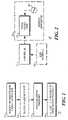
- FIG. 7comprises a detail block diagram as configured in accordance with yet another embodiment of the invention.
- a wireless transmit-only apparatussuch as a remote control transmitter for a movable barrier operator, comprises a controller having a transmission frequency selection output and a wireless transmitter having a phase locked loop that is responsive to the transmission frequency selection output.
- the resultant wireless transmit-only apparatuscan selectively transmit at a plurality of different frequencies as selected by the controller and effected, at least in part, by the phase locked loop. So configured, the apparatus can accommodate differing transmission frequencies as characterize the protocols and requirements of differing manufacturers and systems. This capability in turn permits provision of a cost-effective yet simple-to-use transmitter that can work compatibly and relatively transparently with a variety of different movable barrier operators.
- the phase locked loophas a programmable divider input that operably couples to an oscillator, which oscillator is, in turn, controlled by the controller.
- programmabilitycan include, for example, but is not limited to, selection of one from amongst many possible divider inputs. This configuration permits a relatively cost efficient mechanism to provide the transmitter with a desired level of frequency agility.
- the phase locked loophas a PLL control input that operably couples to a plurality of selectively switchable resonant devices.
- at least one of the resonant devicescomprises a mechanically resonant device and in one embodiment, all of the resonant devices comprise mechanically resonant devices.
- These mechanically resonant devicescan be any suitable mechanically resonant devices as are presently known or hereafter developed, including but not limited to crystal resonators, ceramic resonators, and surface acoustic wave devices.
- a plurality of mechanically resonant devicesare provided, they can all be of a same class of resonant device (for example, they can all be crystal resonators) or they can include resonant devices from differing classes of device.
- the PLL control input of the phase locked loopoperably couples to a single oscillator circuit.
- the single oscillator circuitin turn, switchably couples to a plurality of resonant devices. So configured, the controller selects a particular one of the plurality of resonant devices to operate in conjunction with the oscillator to thereby control the PLL control control input to the phase locked loop. This, in turn, permits control of the oscillation frequency of the oscillator circuit.
- a transmitterthen utilizes this resultant oscillation frequency to influence the transmission carrier frequency utilized to transmit a message.
- the PLL control input of the phase locked loopswitchably couples to a plurality of oscillator circuits.
- Each oscillator circuithas a corresponding resonant device wherein preferably each resultant oscillator circuit will produce a selectively different output oscillation frequency.
- a transmittercan be imbued with frequency agility at a considerably reduced cost as compared to prior art efforts in this regard.
- This economyresults in part through the relatively low cost of virtually all the incremental components required to support such frequency agility.
- Such an approachalso lends itself well to relatively high levels of integration, thereby further contributing to minimized cost and a compact form factor that is relatively friendly to a wide variety of potential applications.
- a process 10provides 11 a transmitter with a phase locked loop, selects 13 an output frequency, and uses 14 that selected frequency as a transmission frequency.
- the phase locked loopwhen providing 11 the transmitter with a phase locked loop, the phase locked loop will support provision of a plurality of selectable output frequencies.
- this phase locked loopwill have a programmable divider value that is responsive to one or more control signals from a controller.
- this phase locked loophas a PLL control input. Both mechanisms are well understood in the art and hence further description will not be provided here for the sake of brevity and the preservation of focus.
- the process 10can provide 12 for an assertable input.
- This assertable inputcan comprise a single assertable input but will comprise, in a preferred approach, a plurality of assertable user inputs.
- Selection 13 of an output frequencycan then be based, at least in part, upon assertion of a given corresponding assertable input. For example, upon detecting assertion of a particular assertable input the process 10 can facilitate selecting one of a plurality of selectable output frequencies as a function thereof.
- Selecting 13 an output frequencycan comprise selecting one of a plurality of resonant elements to operably couple to the PLL control input (where again, the plurality of resonant elements can comprise a least one and preferably at least a plurality of mechanically resonant devices).
- this selection of a resonant elementcan comprise selection of a particular resonant element to use in conjunction with an oscillator or can comprise selection of one oscillator of many wherein each oscillator has at least one corresponding resonant element associated therewith.
- the output of the phase locked loopcan then be used 14 to govern the frequency at which a corresponding transmitter transmits a desired message (such as, for example, a remote control instruction to a movable barrier operator to command the latter to initiate movement of a corresponding movable barrier).
- a desired messagesuch as, for example, a remote control instruction to a movable barrier operator to command the latter to initiate movement of a corresponding movable barrier.
- a transmit-only apparatus 20can be comprised of a controller 21 that operably couples to a wireless transmitter 22 and in particular to a phase locked loop 23 that comprises a part thereof or that otherwise operates in conjunction therewith.
- the controller 21comprises a programmable platform (such as a microprocessor, a microcontroller, a programmable gate array, or the like).
- a programmable platformcan be realized through use of a single integrated platform or the requisite functionality can be distributed over a plurality of supporting platforms in accordance with the needs, requirements, and resources as may apply with respect to a given application.
- the controller 21can comprise an essentially non-programmable platform that serves only the specific functionality set forth herein. Such architectural options are understood in the art and further elaboration here will not be presented for the sake of brevity.
- the controller 21serves, at least in part, to facilitate selection of a particular output frequency (from amongst a plurality of available output frequencies) that the phase locked loop 23 will provide. Pursuant to one approach, the controller 21 can select a particular programmable divide value for the phase locked loop to thereby effect such selection. Pursuant to another approach, the controller 21 can select an input oscillation signal as is applied to a PLL control input of the phase locked loop 23 by an oscillator 24 .
- thiscan be facilitated in a variety of ways, including by selecting from amongst a plurality of resonant devices to use in conjunction with a single oscillator circuit and by selecting from amongst a plurality of oscillator circuits that each have a corresponding (and preferably differing) resonant device.
- the controller 21selects a particular resonant device as a function, at least in part, of a user interface 25 that is operably coupled to the controller 21 .
- this user interface 25comprises at least one independently assertable input.
- FIG. 3a more detailed representation of a more specific embodiment of a wireless transmit-only apparatus 20 provides a plurality of mechanically resonant devices 31 and 32 that are each operably responsive to the controller 21 .
- mechanically resonant devices 31 and 32can be, for example, any of a crystal resonator, a ceramic resonator, a surface acoustic wave device, or the like as appropriate to the needs of a given application.
- Each mechanically resonant device 31 and 32in turn is operably coupled to a PLL control input of the phase locked loop 23 (for example, pursuant to one embodiment, the PLL control input can comprise a the set divider input with other examples being available as well). So configured, the controller 21 can select which of the mechanically resonant devices 31 and 32 is utilized in conjunction with the phase locked loop 23 to influence the frequency of an output signal as provided thereby.
- the controller 21can base its selection of a particular one of the mechanically resonant devices 31 and 32 as a function, at least in part, of the user interface 25 .
- the user interface 25can be comprised of a plurality of independently assertable inputs.
- each independently assertable inputcan be realized through provision of a push-button switch. It would also be possible to provide a variety of different assertable input form factors in a single embodiment to suit, for example, the needs of a given application.
- the controller 21is also operably coupled to a memory 35 (which memory 35 can be remote with respect to the controller 21 or integral thereto and/or which can be comprised of a single platform as illustrated or can be comprised of a plurality of memory platforms, all as well understood in the art).
- This memory 35serves, at least in part, to retain a plurality of characterizing transmission parameters.
- Such transmission parameterscan include specifics that pertain to a given signaling, transmission, and/or control protocol as per the dictates of a corresponding given operating system paradigm.
- the data frame structurecan vary from transmission message to transmission message to reflect such differing requirements.
- the memory 35can include a corresponding characterizing transmission parameter in this regard; i.e., information regarding the data frame structure to be utilized when transmitting a given transmission message.
- a corresponding characterizing transmission parameterin this regard; i.e., information regarding the data frame structure to be utilized when transmitting a given transmission message.
- Other examples of possibly relevant characterizing transmission parametersinclude, but are not limited to, a particular operational code, and a rolling code value and/or an algorithm to facilitate calculation of a next code to transmit (for use with a movable barrier operator that makes use of so-called rolling codes as is otherwise well understood in the art), to name a few.
- the controller 21can correlate a given independently assertable input not only with a specific one of the mechanically resonant devices, but also with a corresponding one (or more) of the plurality of characterizing transmission parameters.
- assertion of a given one of the independently assertable inputswill result in selection of both a particular one of the resonant devices and one or more characterizing transmission parameters.
- characterizing transmission parameterscomprise, at least in part, one or more remote control commands such that each of a plurality of assertable user inputs will correlate with a corresponding remote control command and a corresponding transmission frequency. Fully compatible operation with a plurality of varying systems can be achieved in this way.
- each of the mechanically resonant devices 31 and 32is responsive to a control signal from the controller 21 . This, in turn, permits the controller 21 to select which of the mechanically resonant devices is active and/or otherwise operatively coupled to the PLL control input of the phase locked loop 23 .
- each mechanically resonant device 31 and 32can operably couple to the PLL control input of the phase locked loop 23 via an intervening switch 33 and 34 .
- the controller 21can again select which of the mechanically resonant devices 31 and 32 is operably coupled to the PLL control input of the phase locked loop 23 at any given moment.
- Such switches 33 and 34can be any of a wide variety of switches as are presently known or hereafter developed; present examples include but are not limited to a transistor, a pin diode circuit, and a relay, to name a few.
- each of the resonant devicescomprises a mechanically resonant device.
- the PLL control input of a phase locked loop 23can be selectively coupled to a plurality of resonant devices that include at least one mechanically resonant device 51 and at least one electrically resonant device 52 .
- each of these resonant devices 51 and 52can be made responsive to a control signal from the controller (not shown). Or, if desired and as described above, switches can be utilized to control which of these resonant devices is coupled to the set divided input of the phase locked loop 23 .
- the resonant devices of these embodimentswill work best to properly influence the PLL control input of a phase locked loop 23 when used in conjunction with an oscillator circuit.
- an oscillator 61can be coupled to the PLL control input of the phase locked loop 23 .
- the oscillator 61itself can then couple via in-line switches 63 and 65 to corresponding resonant devices 62 and 64 .
- each switch 63 and 65can be made responsive to the controller (not shown) to thereby permit the controller to control the closed or open state of each switch and hence which of the resonant devices is coupled to the oscillator 61 .
- a single oscillatorworks in conjunction with a plurality of resonant devices to provide the requisite oscillating input to the PLL control input of the phase locked loop 23 .
- a plurality of oscillators 71 and 73can be utilized where each oscillator 71 and 73 has a corresponding resonant device 72 and 74 .
- the oscillatorscan be essentially identical to one another such that the resultant oscillator output will have a frequency that varies one from the other as a function largely of the resonant frequency of the corresponding resonant device.
- a movable barrier operator remote control transmittercan be comprised of at least one assertable user input, a memory containing a plurality of remote control commands for a plurality of different movable barrier operators (wherein at least some of the remote control commands comprise a corresponding transmission frequency that is different from other of the remote control commands), and correlation data that correlates the assertable user input(s) with corresponding remote control commands and hence with a corresponding transmission frequency.
- a controllerthat is operably coupled to the assertable user input, the memory, and the correlation data and having a transmission frequency selection output can effectively control the transmission frequency and the message format/content of an operably coupled wireless transmitter having frequency agility owing to a selectively-variable output frequency phase locked loop.
Landscapes
- Engineering & Computer Science (AREA)
- Computer Networks & Wireless Communication (AREA)
- Physics & Mathematics (AREA)
- General Physics & Mathematics (AREA)
- Transmitters (AREA)
- Selective Calling Equipment (AREA)
Abstract
Description
Claims (12)
Priority Applications (1)
| Application Number | Priority Date | Filing Date | Title |
|---|---|---|---|
| US11/555,024US7610030B2 (en) | 2003-08-21 | 2006-10-31 | Wireless transmit-only apparatus and method |
Applications Claiming Priority (2)
| Application Number | Priority Date | Filing Date | Title |
|---|---|---|---|
| US10/645,318US7181174B2 (en) | 2003-08-21 | 2003-08-21 | Wireless transmit-only apparatus and method |
| US11/555,024US7610030B2 (en) | 2003-08-21 | 2006-10-31 | Wireless transmit-only apparatus and method |
Related Parent Applications (1)
| Application Number | Title | Priority Date | Filing Date |
|---|---|---|---|
| US10/645,318ContinuationUS7181174B2 (en) | 2003-08-21 | 2003-08-21 | Wireless transmit-only apparatus and method |
Publications (2)
| Publication Number | Publication Date |
|---|---|
| US20070054644A1 US20070054644A1 (en) | 2007-03-08 |
| US7610030B2true US7610030B2 (en) | 2009-10-27 |
Family
ID=33098444
Family Applications (2)
| Application Number | Title | Priority Date | Filing Date |
|---|---|---|---|
| US10/645,318Expired - LifetimeUS7181174B2 (en) | 2003-08-21 | 2003-08-21 | Wireless transmit-only apparatus and method |
| US11/555,024Expired - LifetimeUS7610030B2 (en) | 2003-08-21 | 2006-10-31 | Wireless transmit-only apparatus and method |
Family Applications Before (1)
| Application Number | Title | Priority Date | Filing Date |
|---|---|---|---|
| US10/645,318Expired - LifetimeUS7181174B2 (en) | 2003-08-21 | 2003-08-21 | Wireless transmit-only apparatus and method |
Country Status (7)
| Country | Link |
|---|---|
| US (2) | US7181174B2 (en) |
| AU (1) | AU2004205107A1 (en) |
| CA (1) | CA2477028C (en) |
| DE (1) | DE102004040440A1 (en) |
| FR (1) | FR2859053A1 (en) |
| GB (1) | GB2405248B (en) |
| MX (1) | MXPA04008090A (en) |
Cited By (2)
| Publication number | Priority date | Publication date | Assignee | Title |
|---|---|---|---|---|
| US10643411B1 (en) | 2018-10-05 | 2020-05-05 | Gmi Holdings, Inc. | Universal barrier operator transmitter |
| US11378469B2 (en)* | 2016-07-01 | 2022-07-05 | Continental Automotive Gmbh | Method and apparatus for identifying a force exerted by a seat or closing part |
Families Citing this family (23)
| Publication number | Priority date | Publication date | Assignee | Title |
|---|---|---|---|---|
| US7181174B2 (en)* | 2003-08-21 | 2007-02-20 | The Chamberlain Group, Inc. | Wireless transmit-only apparatus and method |
| US7174137B2 (en)* | 2003-08-21 | 2007-02-06 | The Chamberlain Group, Inc. | Wireless transmit-only apparatus and method |
| US7724126B2 (en)* | 2004-07-29 | 2010-05-25 | The Chamberlain Group, Inc. | Movable barrier operator operating parameter transfer method and apparatus |
| US7482885B2 (en)* | 2005-12-29 | 2009-01-27 | Orca Systems, Inc. | Method of frequency synthesis for fast switching |
| US8221690B2 (en) | 2007-10-30 | 2012-07-17 | The Invention Science Fund I, Llc | Systems and devices that utilize photolyzable nitric oxide donors |
| US7862598B2 (en)* | 2007-10-30 | 2011-01-04 | The Invention Science Fund I, Llc | Devices and systems that deliver nitric oxide |
| US20110190604A1 (en)* | 2006-12-22 | 2011-08-04 | Hyde Roderick A | Nitric oxide sensors and systems |
| US7975699B2 (en) | 2007-10-30 | 2011-07-12 | The Invention Science Fund I, Llc | Condoms configured to facilitate release of nitric oxide |
| US20090110933A1 (en)* | 2007-10-30 | 2009-04-30 | Searete Llc, A Limited Liability Corporation Of The State Of Delaware | Systems and devices related to nitric oxide releasing materials |
| US8642093B2 (en)* | 2007-10-30 | 2014-02-04 | The Invention Science Fund I, Llc | Methods and systems for use of photolyzable nitric oxide donors |
| US7843363B2 (en)* | 2007-07-12 | 2010-11-30 | Rosemount Aerospace Inc. | Mechanical latch locking detection sensors |
| US7661321B2 (en)* | 2007-09-25 | 2010-02-16 | Rosemount Aerospace Inc. | Force sensing clevis insert |
| US8877508B2 (en)* | 2007-10-30 | 2014-11-04 | The Invention Science Fund I, Llc | Devices and systems that deliver nitric oxide |
| US8349262B2 (en)* | 2007-10-30 | 2013-01-08 | The Invention Science Fund I, Llc | Nitric oxide permeable housings |
| US7897399B2 (en) | 2007-10-30 | 2011-03-01 | The Invention Science Fund I, Llc | Nitric oxide sensors and systems |
| US20090112193A1 (en)* | 2007-10-30 | 2009-04-30 | Searete Llc, A Limited Liability Corporation Of The State Of Delaware | Systems and devices that utilize photolyzable nitric oxide donors |
| US8980332B2 (en) | 2007-10-30 | 2015-03-17 | The Invention Science Fund I, Llc | Methods and systems for use of photolyzable nitric oxide donors |
| US10080823B2 (en) | 2007-10-30 | 2018-09-25 | Gearbox Llc | Substrates for nitric oxide releasing devices |
| US20090112055A1 (en)* | 2007-10-30 | 2009-04-30 | Searete Llc, A Limited Liability Corporation Of The State Of Delaware | Sleeves configured to facilitate release of nitric oxide |
| US20110019342A1 (en)* | 2009-07-27 | 2011-01-27 | Justin Moore | Remote control |
| USD613256S1 (en) | 2009-07-27 | 2010-04-06 | Justin Moore | Remote control |
| US20130077641A1 (en)* | 2011-09-22 | 2013-03-28 | Harley F. Burger, Jr. | Systems, Circuits and Methods for Time Stamp Based One-Way Communications |
| US10096187B2 (en) | 2015-04-09 | 2018-10-09 | Overhead Door Corporation | Automatic transmission of a barrier status and change of status over a network |
Citations (34)
| Publication number | Priority date | Publication date | Assignee | Title |
|---|---|---|---|---|
| US3576482A (en) | 1969-08-27 | 1971-04-27 | Sylvania Electric Prod | Relay control system for plurality of bidirectional motors |
| US3869671A (en) | 1972-04-10 | 1975-03-04 | Int Standard Electric Corp | Method of and circuit arrangement for operating a control-signal transmitter for remote-control equipment |
| US4021756A (en) | 1975-07-02 | 1977-05-03 | Zenith Radio Corporation | Electric remote control transmitter |
| US4706727A (en) | 1984-05-11 | 1987-11-17 | Firmagroup Australia Pty. Ltd. | Door operator |
| US4794622A (en) | 1985-06-03 | 1988-12-27 | Linear Corporation | Low power transmitter frequency stabilization |
| JPH0446494A (en) | 1990-06-13 | 1992-02-17 | Fujitsu General Ltd | Remote control signal transmitter and receiver |
| US5222327A (en) | 1991-07-22 | 1993-06-29 | Fellows Donna M | Side mount garage door operator |
| US5335307A (en) | 1992-02-18 | 1994-08-02 | Sommer William F | Precision electric motor speed |
| US5334876A (en) | 1992-04-22 | 1994-08-02 | Nartron Corporation | Power window or panel controller |
| US5557887A (en) | 1994-06-29 | 1996-09-24 | Jerry W. Fellows | Yieldable gearing and safety mechanisms for garage door operators |
| US5564101A (en) | 1993-07-09 | 1996-10-08 | Universal Devices | Method and apparatus for transmitter for universal garage door opener |
| GB2300997A (en) | 1995-05-19 | 1996-11-20 | Prince Corp | A Trainable Remote Control Actuator |
| GB2300944A (en) | 1995-05-19 | 1996-11-20 | Prince Corp | Trainable remote control transceiver |
| GB2300945A (en) | 1995-05-19 | 1996-11-20 | Prince Corp | Trainable transmitter having variable gain control |
| GB2301961A (en) | 1995-05-19 | 1996-12-18 | Prince Corp | Trainable RF transceiver with an improved phase-locked loop circuit |
| US6005508A (en) | 1994-07-05 | 1999-12-21 | Tsui; Philip Y. W. | Remote transmitter-receiver controller system |
| US6014307A (en) | 1998-03-24 | 2000-01-11 | The Chamberlain Group, Inc. | Fire door operator having an integrated electronically controlled descent device |
| US6137255A (en) | 1999-07-30 | 2000-10-24 | Otis Elevator Company | Apparatus and method of controlling a linear motor door operator |
| US6137421A (en)* | 1997-11-12 | 2000-10-24 | Prince Corporation | Method and apparatus for storing a data encoded signal |
| US6172475B1 (en) | 1998-09-28 | 2001-01-09 | The Chamberlain Group, Inc. | Movable barrier operator |
| US6326751B1 (en) | 1999-08-25 | 2001-12-04 | Wayne-Dalton Corp. | System and related methods for detecting and measuring the operational parameters of a garage door utilizing a lift cable system |
| US6356082B1 (en) | 2000-05-26 | 2002-03-12 | Schonstedt Instruments Co. | Utility locator radio link |
| US6486795B1 (en) | 1998-07-31 | 2002-11-26 | The Chamberlain Group, Inc. | Universal transmitter |
| US20030073417A1 (en) | 2001-10-11 | 2003-04-17 | Lear Corporation | Transmitter circuit, article of manufacture, and method of transmitting |
| WO2003051085A1 (en) | 2001-12-08 | 2003-06-19 | Seongho Ko | Method and apparatus for setting radio frequency for use in remote controller |
| DE10226294A1 (en) | 2002-06-13 | 2003-12-24 | Kostal Leopold Gmbh & Co Kg | Car high frequency radio keyless entry system has microcontroller selected transmitter and receiver for two frequency bands |
| US6766178B1 (en)* | 1998-04-08 | 2004-07-20 | Skyworks Solutions, Inc. | RF architecture for cellular multi-band telephones |
| US20040207537A1 (en) | 2001-04-25 | 2004-10-21 | Keller Robert Roy | Simplified method and apparatus for programming a universal transmitter |
| US6822603B1 (en) | 2000-04-25 | 2004-11-23 | The Chamberlain Group, Inc. | Method and apparatus for transmitting a plurality of different codes at a plurality of different frequencies |
| US20050012488A1 (en) | 2003-07-18 | 2005-01-20 | The Chamberlain Group, Inc. | Barrier movement operator speed control |
| US6952087B2 (en) | 2000-10-27 | 2005-10-04 | Robert Bosch Gmbh | Method for controlling an adjustment process of a part |
| US7174137B2 (en) | 2003-08-21 | 2007-02-06 | The Chamberlain Group, Inc. | Wireless transmit-only apparatus and method |
| US7181174B2 (en) | 2003-08-21 | 2007-02-20 | The Chamberlain Group, Inc. | Wireless transmit-only apparatus and method |
| US7205735B2 (en) | 2004-01-16 | 2007-04-17 | The Chamberlain Group, Inc. | Barrier movement operator having obstruction detection |
Family Cites Families (7)
| Publication number | Priority date | Publication date | Assignee | Title |
|---|---|---|---|---|
| DE4007454A1 (en)* | 1990-03-09 | 1991-09-12 | Int Patent Utilization | Golf ball location arrangement with signal receiver unit |
| US5608758A (en)* | 1992-07-15 | 1997-03-04 | Futaba Denshi Kogyo, K.K. | Radio control device having crystal high frequency module and high frequency phase lockloop for selective use, modules detachably mounted |
| US5841390A (en)* | 1994-07-05 | 1998-11-24 | Tsui; Philip Y. W. | Remote transmitter-receiver controller for multiple systems |
| WO2000020712A1 (en)* | 1998-10-05 | 2000-04-13 | Lear Automotive Dearborn, Inc. | Multiple channel remote keyless entry system |
| DE19924017A1 (en)* | 1999-05-26 | 2000-12-07 | Siemens Ag | Method and device for simplex data transmission |
| US6703941B1 (en)* | 1999-08-06 | 2004-03-09 | Johnson Controls Technology Company | Trainable transmitter having improved frequency synthesis |
| US20020137460A1 (en)* | 2001-03-08 | 2002-09-26 | Howard Sun | Universal multi-band (5 bands and more) keyless RF remote control unit using bluetooth radio module as the base |
- 2003
- 2003-08-21USUS10/645,318patent/US7181174B2/ennot_activeExpired - Lifetime
- 2004
- 2004-08-09CACA2477028Apatent/CA2477028C/ennot_activeExpired - Lifetime
- 2004-08-13AUAU2004205107Apatent/AU2004205107A1/ennot_activeAbandoned
- 2004-08-19FRFR0408988Apatent/FR2859053A1/enactivePending
- 2004-08-20GBGB0418635Apatent/GB2405248B/ennot_activeExpired - Fee Related
- 2004-08-20DEDE102004040440Apatent/DE102004040440A1/ennot_activeWithdrawn
- 2004-08-20MXMXPA04008090Apatent/MXPA04008090A/ennot_activeApplication Discontinuation
- 2006
- 2006-10-31USUS11/555,024patent/US7610030B2/ennot_activeExpired - Lifetime
Patent Citations (34)
| Publication number | Priority date | Publication date | Assignee | Title |
|---|---|---|---|---|
| US3576482A (en) | 1969-08-27 | 1971-04-27 | Sylvania Electric Prod | Relay control system for plurality of bidirectional motors |
| US3869671A (en) | 1972-04-10 | 1975-03-04 | Int Standard Electric Corp | Method of and circuit arrangement for operating a control-signal transmitter for remote-control equipment |
| US4021756A (en) | 1975-07-02 | 1977-05-03 | Zenith Radio Corporation | Electric remote control transmitter |
| US4706727A (en) | 1984-05-11 | 1987-11-17 | Firmagroup Australia Pty. Ltd. | Door operator |
| US4794622A (en) | 1985-06-03 | 1988-12-27 | Linear Corporation | Low power transmitter frequency stabilization |
| JPH0446494A (en) | 1990-06-13 | 1992-02-17 | Fujitsu General Ltd | Remote control signal transmitter and receiver |
| US5222327A (en) | 1991-07-22 | 1993-06-29 | Fellows Donna M | Side mount garage door operator |
| US5335307A (en) | 1992-02-18 | 1994-08-02 | Sommer William F | Precision electric motor speed |
| US5334876A (en) | 1992-04-22 | 1994-08-02 | Nartron Corporation | Power window or panel controller |
| US5564101A (en) | 1993-07-09 | 1996-10-08 | Universal Devices | Method and apparatus for transmitter for universal garage door opener |
| US5557887A (en) | 1994-06-29 | 1996-09-24 | Jerry W. Fellows | Yieldable gearing and safety mechanisms for garage door operators |
| US6005508A (en) | 1994-07-05 | 1999-12-21 | Tsui; Philip Y. W. | Remote transmitter-receiver controller system |
| GB2300997A (en) | 1995-05-19 | 1996-11-20 | Prince Corp | A Trainable Remote Control Actuator |
| GB2300944A (en) | 1995-05-19 | 1996-11-20 | Prince Corp | Trainable remote control transceiver |
| GB2300945A (en) | 1995-05-19 | 1996-11-20 | Prince Corp | Trainable transmitter having variable gain control |
| GB2301961A (en) | 1995-05-19 | 1996-12-18 | Prince Corp | Trainable RF transceiver with an improved phase-locked loop circuit |
| US6137421A (en)* | 1997-11-12 | 2000-10-24 | Prince Corporation | Method and apparatus for storing a data encoded signal |
| US6014307A (en) | 1998-03-24 | 2000-01-11 | The Chamberlain Group, Inc. | Fire door operator having an integrated electronically controlled descent device |
| US6766178B1 (en)* | 1998-04-08 | 2004-07-20 | Skyworks Solutions, Inc. | RF architecture for cellular multi-band telephones |
| US6486795B1 (en) | 1998-07-31 | 2002-11-26 | The Chamberlain Group, Inc. | Universal transmitter |
| US6172475B1 (en) | 1998-09-28 | 2001-01-09 | The Chamberlain Group, Inc. | Movable barrier operator |
| US6137255A (en) | 1999-07-30 | 2000-10-24 | Otis Elevator Company | Apparatus and method of controlling a linear motor door operator |
| US6326751B1 (en) | 1999-08-25 | 2001-12-04 | Wayne-Dalton Corp. | System and related methods for detecting and measuring the operational parameters of a garage door utilizing a lift cable system |
| US6822603B1 (en) | 2000-04-25 | 2004-11-23 | The Chamberlain Group, Inc. | Method and apparatus for transmitting a plurality of different codes at a plurality of different frequencies |
| US6356082B1 (en) | 2000-05-26 | 2002-03-12 | Schonstedt Instruments Co. | Utility locator radio link |
| US6952087B2 (en) | 2000-10-27 | 2005-10-04 | Robert Bosch Gmbh | Method for controlling an adjustment process of a part |
| US20040207537A1 (en) | 2001-04-25 | 2004-10-21 | Keller Robert Roy | Simplified method and apparatus for programming a universal transmitter |
| US20030073417A1 (en) | 2001-10-11 | 2003-04-17 | Lear Corporation | Transmitter circuit, article of manufacture, and method of transmitting |
| WO2003051085A1 (en) | 2001-12-08 | 2003-06-19 | Seongho Ko | Method and apparatus for setting radio frequency for use in remote controller |
| DE10226294A1 (en) | 2002-06-13 | 2003-12-24 | Kostal Leopold Gmbh & Co Kg | Car high frequency radio keyless entry system has microcontroller selected transmitter and receiver for two frequency bands |
| US20050012488A1 (en) | 2003-07-18 | 2005-01-20 | The Chamberlain Group, Inc. | Barrier movement operator speed control |
| US7174137B2 (en) | 2003-08-21 | 2007-02-06 | The Chamberlain Group, Inc. | Wireless transmit-only apparatus and method |
| US7181174B2 (en) | 2003-08-21 | 2007-02-20 | The Chamberlain Group, Inc. | Wireless transmit-only apparatus and method |
| US7205735B2 (en) | 2004-01-16 | 2007-04-17 | The Chamberlain Group, Inc. | Barrier movement operator having obstruction detection |
Non-Patent Citations (2)
| Title |
|---|
| British Search Report from corresponding application GB 04 186 35.9 dated Nov. 26, 2004. |
| International Search Report, dated Aug. 27, 2004, in PCT application PCT/US04/01157. |
Cited By (3)
| Publication number | Priority date | Publication date | Assignee | Title |
|---|---|---|---|---|
| US11378469B2 (en)* | 2016-07-01 | 2022-07-05 | Continental Automotive Gmbh | Method and apparatus for identifying a force exerted by a seat or closing part |
| US10643411B1 (en) | 2018-10-05 | 2020-05-05 | Gmi Holdings, Inc. | Universal barrier operator transmitter |
| US10891812B2 (en) | 2018-10-05 | 2021-01-12 | Gmi Holdings, Inc. | Universal barrier operator transmitter |
Also Published As
| Publication number | Publication date |
|---|---|
| GB2405248A (en) | 2005-02-23 |
| AU2004205107A1 (en) | 2005-03-10 |
| FR2859053A1 (en) | 2005-02-25 |
| GB2405248B (en) | 2006-09-27 |
| DE102004040440A1 (en) | 2005-03-17 |
| US7181174B2 (en) | 2007-02-20 |
| US20070054644A1 (en) | 2007-03-08 |
| GB0418635D0 (en) | 2004-09-22 |
| CA2477028A1 (en) | 2005-02-21 |
| CA2477028C (en) | 2013-09-24 |
| US20050042991A1 (en) | 2005-02-24 |
| MXPA04008090A (en) | 2008-09-01 |
Similar Documents
| Publication | Publication Date | Title |
|---|---|---|
| US7610030B2 (en) | Wireless transmit-only apparatus and method | |
| US5787528A (en) | Method and apparatus for providing bed recall functions | |
| US6308083B2 (en) | Integrated cellular telephone with programmable transmitter | |
| JPH01218296A (en) | Remote control receiver with study function | |
| US20050003771A1 (en) | Method and apparatus for automatic tuning of a resonant loop antenna in a transceiver circuit | |
| GB2301961B (en) | Trainable RF transceiver with improved phase-locked loop circuit | |
| US7006802B2 (en) | Universal transmitter | |
| US9443422B2 (en) | Frequency shifting method for universal transmitters | |
| US20050181742A1 (en) | Radio control system for models | |
| US8055219B2 (en) | Frequency agile antenna system and method | |
| EP1559199B1 (en) | RF circuit with frequency agile seqential amplifiers | |
| US5697068A (en) | System and method for providing a non-invasively tunable transceiver synthesizer | |
| US7174137B2 (en) | Wireless transmit-only apparatus and method | |
| US20110032116A1 (en) | Universal Transmitter | |
| JP3806699B2 (en) | Wireless microphone system, receiver, wireless microphone | |
| KR100255554B1 (en) | Radio control for two-way communication | |
| JPH06132847A (en) | Transmission / reception frequency band switching type wireless communication device | |
| JPH0520020Y2 (en) | ||
| EP1865599A3 (en) | Portable radio terminal and AFC control method | |
| KR20040023317A (en) | A frequency control davice and method of air conditioner | |
| JP2001128258A (en) | Remote control device | |
| US6415136B1 (en) | Method of minimizing interference between devices which communicate in overlapping communication bands | |
| JP2001237738A (en) | Radio receiver, radio transmitter and radio communication unit | |
| JPH063945B2 (en) | Receiver | |
| JP2003283360A (en) | Radio, tuning frequency setting system, and tuning frequency setting method |
Legal Events
| Date | Code | Title | Description |
|---|---|---|---|
| STCF | Information on status: patent grant | Free format text:PATENTED CASE | |
| CC | Certificate of correction | ||
| FPAY | Fee payment | Year of fee payment:4 | |
| FPAY | Fee payment | Year of fee payment:8 | |
| MAFP | Maintenance fee payment | Free format text:PAYMENT OF MAINTENANCE FEE, 12TH YEAR, LARGE ENTITY (ORIGINAL EVENT CODE: M1553); ENTITY STATUS OF PATENT OWNER: LARGE ENTITY Year of fee payment:12 | |
| AS | Assignment | Owner name:ARES CAPITAL CORPORATION, AS COLLATERAL AGENT, NEW YORK Free format text:SECOND LIEN PATENT SECURITY AGREEMENT;ASSIGNORS:THE CHAMBERLAIN GROUP LLC;SYSTEMS, LLC;REEL/FRAME:058015/0001 Effective date:20211103 Owner name:WELLS FARGO BANK, NATIONAL ASSOCIATION, AS COLLATERAL AGENT, COLORADO Free format text:FIRST LIEN PATENT SECURITY AGREEMENT;ASSIGNORS:THE CHAMBERLAIN GROUP LLC;SYSTEMS, LLC;REEL/FRAME:058014/0931 Effective date:20211103 | |
| AS | Assignment | Owner name:SYSTEMS, LLC, ILLINOIS Free format text:NOTICE OF TERMINATION AND RELEASE OF SECURITY INTEREST IN PATENTS;ASSIGNOR:ARES CAPITAL CORPORATION, AS COLLATERAL AGENT;REEL/FRAME:066374/0749 Effective date:20240126 Owner name:THE CHAMBERLAIN GROUP LLC, ILLINOIS Free format text:NOTICE OF TERMINATION AND RELEASE OF SECURITY INTEREST IN PATENTS;ASSIGNOR:ARES CAPITAL CORPORATION, AS COLLATERAL AGENT;REEL/FRAME:066374/0749 Effective date:20240126 |