US7609961B2 - Vehicle camera - Google Patents
Vehicle cameraDownload PDFInfo
- Publication number
- US7609961B2 US7609961B2US11/401,405US40140506AUS7609961B2US 7609961 B2US7609961 B2US 7609961B2US 40140506 AUS40140506 AUS 40140506AUS 7609961 B2US7609961 B2US 7609961B2
- Authority
- US
- United States
- Prior art keywords
- vehicle
- lens
- camera
- base
- camera body
- Prior art date
- Legal status (The legal status is an assumption and is not a legal conclusion. Google has not performed a legal analysis and makes no representation as to the accuracy of the status listed.)
- Active - Reinstated, expires
Links
Images


Classifications
- G—PHYSICS
- G03—PHOTOGRAPHY; CINEMATOGRAPHY; ANALOGOUS TECHNIQUES USING WAVES OTHER THAN OPTICAL WAVES; ELECTROGRAPHY; HOLOGRAPHY
- G03B—APPARATUS OR ARRANGEMENTS FOR TAKING PHOTOGRAPHS OR FOR PROJECTING OR VIEWING THEM; APPARATUS OR ARRANGEMENTS EMPLOYING ANALOGOUS TECHNIQUES USING WAVES OTHER THAN OPTICAL WAVES; ACCESSORIES THEREFOR
- G03B17/00—Details of cameras or camera bodies; Accessories therefor
Definitions
- the present inventionrelates to a camera, and more particularly, to a camera mounted on a vehicle.
- the present inventionis suitable for a wide scope of applications, it is particularly suitable for retrofitting a camera onto a vehicle.
- a blind spot of a vehicleis an area near the vehicle that the driver can not readily see.
- Some blind spotsare alleviated by the use of mirrors.
- some blind spotscan only be monitored through the use of convex mirrors. Because of the visual distortion of a convex mirror, objects may be hard to discern in the convex mirror. Further, the relative distance of an object is difficult to assess in a convex mirror.
- a cameracan be mounted on the rear of a vehicle so that the driver can see behind the vehicle while backing up the vehicle.
- larger vehicles, such as buses and recreational vehicleshave blind spots at the sides of the vehicle.
- a cameracan be mounted on a side of a vehicle or rear part of the vehicle such that a driver can see in a blind spot at the side of the vehicle.
- the mounting of a camerais usually a retrofit or an add-on to a vehicle. In other words, the original styling of most vehicles does not include a built-in camera or a provision for an add-on camera.
- FIG. 1is an illustration of a related art vehicle camera on a side of a vehicle.
- the related art vehicle camera 1includes a camera body 10 mounted on a bracket 11 attached to the side of the vehicle 12 .
- a housing 13 having window 14 for the camera body 10is attached to the bracket 11 with bolts 15 .
- the relate art vehicle camerais obtrusive in appearance as compared to the original body style of the vehicle before the addition of the related art vehicle camera. Further, the related art vehicle camera blatantly has the appearance of being a camera such that theft of the related art vehicle camera is more probable. Furthermore, the related art vehicle camera requires drilling a hole in the vehicle or otherwise creating a mounting point on the vehicle.
- the present inventionis directed to a vehicle camera that substantially obviates one or more of the problems due to limitations and disadvantages of the related art.
- An object of the present inventionis to provide a vehicle camera that can be readily retrofitted to a vehicle.
- Another object of the present inventionis to provide a vehicle camera that is unobtrusive in appearance on a vehicle.
- the vehicle cameraincludes a vehicle lens having an opening, a camera body within the vehicle lens having a viewing axis through the opening, a base attached to the vehicle lens, wherein the viewing axis is at an angle between about 15 to 75 degrees with respect to a plane of the base.
- the vehicle cameraincludes a vehicle lens for use as a vehicle light, a camera body within the vehicle lens having a viewing axis, and a base containing a wireless transmission circuit for wirelessly transmitting video signals to a receiver, the vehicle lens being attached to the base.
- the vehicle cameraincludes a vehicle lens for use as a vehicle light, a camera body mounted completely within the vehicle lens, a transparent camera lens cover attached to the vehicle lens for protecting a camera lens within the camera body, and a base for mounting on a vehicle, the vehicle lens being attached to the base.
- FIG. 1is an illustration of a related art vehicle camera on a side of a vehicle.
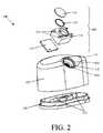
- FIG. 2is an exploded view of a vehicle camera according to a first embodiment of the present invention.
- FIG. 3is a cross-sectional view of the vehicle camera attached to the side of a vehicle according to a first embodiment of the present invention.
- FIG. 4is an exploded view of a vehicle camera according to a second embodiment of the present invention.
- FIG. 5is a cross-sectional view of the vehicle camera attached to the side of a vehicle according to a second embodiment of the present invention.
- FIG. 2is an exploded view of a vehicle camera according to a first embodiment of the present invention.
- FIG. 2is an exemplary first embodiment of the invention implemented in 2′′ ⁇ 4′′ type vehicle light.
- a vehicle camera 100includes a camera assembly 110 for mounting on a vehicle lens 120 that attaches to a base 130 .
- the camera assembly 110is attached within the vehicle lens 120 .
- the base 130which is either original equipment on the vehicle or a retrofit to the vehicle, is attached to the vehicle lens 120 .
- the camera assembly 110 of the vehicle camera 100includes a camera body 111 with a camera body cover 112 .
- the camera body 111houses optoelectronic components (not shown) used to convert an optical image into electronic signals.
- the camera body cover 112can allow access to the optoelectronic components.
- the camera body 111also has mounting tabs 115 for directly attaching the camera body 111 to the interior surface of the vehicle lens 120 .
- the camera assembly 110also includes a gasket 113 for providing a water tight seal between the camera body 111 and the vehicle lens 120 .
- the camera assembly 110can also include a transparent camera lens cover 114 to protect the camera lens in the camera body 111 .
- the vehicle lens 120can be any color that is used on vehicles as either a marker light, side light, brake light, tail light or reverse light.
- the vehicle lens 120can be yellow or ember for use as a side marker light, blue for use as a marker light, red for use as a tail light or white for use as a reverse light.
- the vehicle lens 120can not only serve to emit a specific color but can also be a reflector by having an interior surface or surfaces of the vehicle lens 120 contoured to reflect ambient light as the specific color.
- the exterior shape of the vehicle lens 120is similar to a typical 2′′ ⁇ 4′′ vehicle lens except for a concave portion 121 along a top edge that is opposite to a bottom edge, which is adjacent to the base 130 when the vehicle lens is attached to the base 130 .
- the concave portion 121includes a first recess 122 for mounting the camera lens cover 114 on the outside of the vehicle lens 120 and a second recess 123 for receiving the camera body 111 from the inside of the vehicle lens 120 . More specifically, the second recess 123 has an opening 124 within which the camera body is positioned such that the viewing axis of the camera body 111 goes through the opening 124 .
- the second recess 123 of the concave portion 121can be oriented such that the viewing axis of the camera body 111 is at about a 45 degree angle with respect to the plane of the base 130 .
- Other viewing axescan be obtained by forming the vehicle lens to have a concave portion 121 with a second recess at other angles with respect to the plane of the base 130 .
- a kit for mounting a vehicle cameracould come with a base 130 , a camera assembly 110 , and an assortment of 15 degree, 30 degree, 45 degree, 60 degree and 75 degree vehicle lenses such that a user can choose the appropriate viewing axis for a particular application.
- a viewing angle of about 90 degreesis appropriate.
- the first recess 122 and second recess 123are formed in the top surface of the vehicle lens 220 that is parallel to the plane of the base 230 .
- the base 130is for mounting onto the vehicle 140 and for holding light bulbs 131 , which provide light in response to power provided by the wiring 132 .
- FIG. 2shows two light bulbs 131
- the base 130can be configured to hold one light bulb, three light bulbs or more than three light bulbs.
- a light bulbcan be incandescent or a light emitting diode.
- the base 130can either be original equipment or a retrofit.
- a usercan either mount a vehicle camera using an existing base of a vehicle light, use the base of the first embodiment by attaching the base of the first embodiment to a vehicle using the mounting holes in the vehicle for previous base of a vehicle light, or retrofit a base of the first embodiment for the purpose of mounting the vehicle camera.
- An existing basemay have to be modified by drilling a hole through the base to pass through wires from a monitor (not shown) to the camera body 111 .
- the base of the first embodimentmay already have a hole for the wires from the monitor (not shown) that connect to the camera body but the base of the first embodiment may have to be mounted to the vehicle by providing a new mounting area on the vehicle or using a preexisting mounting area on the vehicle. If the base of the first embodiment base is provided on a new mounting area on the vehicle and if an additional vehicle light is desired, wiring may need to be provided to the bulbs of the base of the first embodiment.
- FIG. 3is a cross-sectional view of the first embodiment of the vehicle camera attached to the side of vehicle according to a first embodiment of the present invention.
- the camera body 111 of the vehicle camera 100is attached to the vehicle lens 120 so as to be within an opening of the second recess 123 with the gasket 113 between the camera body 111 and the vehicle lens 120 .
- the camera body 111can be attached to the vehicle lens 120 by sliding the mounting tabs 115 into receptacles within the vehicle lens 120 and/or adhesively attaching the mounting tabs 115 to the vehicle lens 120 .
- Wires 116 from the camera body 111pass through the base 130 .
- the camera lens cover 114can be attached within the first recess 121 of the vehicle lens 120 with an adhesive.
- the camera body 111is completely within the vehicle lens 120 . No part of the camera is outside of the vehicle lens 120 . Such a structure conceals the camera.
- FIG. 4is an exploded view of a vehicle camera according to a second embodiment of the present invention.
- FIG. 4is an exemplary second embodiment of the invention implemented in 2′′ ⁇ 6′′ type vehicle light.
- a vehicle camera 100includes a camera assembly 210 for mounting on a vehicle lens 220 that attaches to a base 230 .
- the camera assembly 210is attached within the vehicle lens 220 .
- the base 230which is either original equipment on the vehicle or is a retrofit to the vehicle, is attached to the vehicle lens 220 .
- the camera assembly 210 of the vehicle camera 200includes a camera body 211 with a camera body cover 212 .
- the camera body 211houses optoelectronic components (not shown) used to convert an optical image into electronic signals.
- the camera body cover 212can allow access to the optoelectronic components.
- the camera body 211also has mounting tabs 215 for directly attaching the camera body 211 to the interior surface of the vehicle lens 220 .
- the camera assembly 210includes a transparent camera lens cover 214 to protect the camera lens in the camera body 211 .
- the camera assembly 210also includes a gasket 213 for providing a water tight seal between the camera lens cover 214 and the vehicle lens 220 .
- the vehicle lens 220 of the second embodimentcan be any color that is used on vehicles as either a marker light, side light, brake light, tail light or reverse light.
- the vehicle lens 220can be yellow or ember for use as a side light, red for use as a tail light, blue for use as a marker light or white for use as a reverse light.
- the vehicle lens 220can not only serve to emit a specific color but can also be a reflector by having an interior surface or surfaces of the vehicle lens 220 contoured to reflect ambient light as the specific color.
- the exterior shape of the vehicle lens 220is similar to a typical 2′′ ⁇ 6′′ vehicle lens except for a slanted top surface 221 having concave portion 222 that can have the same inclination as the slanted top surface of the vehicle lens 220 .
- the concave portion 221can have a different inclination from the slanted top surface 221 of the vehicle lens 220 .
- the concave portion 222includes an opening 223 at which the camera lens cover 214 and the camera body 211 is attached at the inside of the vehicle lens 220 . More specifically, the concave portion 222 has an opening 223 at which the camera body is positioned such that the viewing axis of the camera body 211 goes through the opening 223 .
- the concave portion 222can be oriented such that the viewing axis of the camera body 211 is at about a 45 degree angle with respect to a plane of the base 230 .
- Other viewing axescan be obtained by forming the vehicle lens to have a concave portion 222 at other angles with respect to the plane of the base 230 .
- the concave portioncan be at an angle similar to the top slanted surface of a typical 2′′ ⁇ 6′′ vehicle lens or have an angle within a range of about 15 to 75 degrees with respect to the plane of the base 230 .
- a viewing angle of about 90 degreesis appropriate.
- the opening 223is formed in the surface of the vehicle lens 220 that is parallel to the plane of the base 230 .
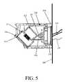
- the base 230is for mounting onto the vehicle 240 and for holding light bulbs 231 , which provide light. As discussed with regard to the previous embodiment, the base 230 can be configured to hold one light bulb, three light bulbs or more than three light bulbs. As discussed previously, the base 230 can either be original equipment or a retrofit. Further, the base 230 can contain a wireless transmission circuit 232 for wirelessly transmitting video signals received from the camera body 211 . An external antenna 235 can extend from the wireless transmission circuit 232 .
- FIG. 5is a cross-sectional view of the vehicle camera attached to the side of a vehicle according to a second embodiment of the present invention.
- the camera body 211 of the vehicle camera 200is attached within the vehicle lens 220 so that the gasket 213 is between the camera lens cover 214 and the vehicle lens 220 .
- the camera body 211can be attached to vehicle lens 220 by sliding the mounting tabs 215 into receptacles within the vehicle lens 220 and/or adhesively attaching the mounting tabs 215 to the vehicle lens 220 .
- Wires 216 from the camera body 211are connected to the wireless transmission circuit for wirelessly broadcasting video signals.
- a receiverreceives the wirelessly transmitting video signals and displays the video signals on a monitor (not shown) for a driver to see.
- the camera body 211is completely within the vehicle lens 220 . No part of the camera is outside of the vehicle lens 220 . Such a structure conceals the camera.
- a usercan either mount a vehicle camera using an existing base of a vehicle light, use the base of the second embodiment by attaching the base of the second embodiment to a vehicle using the mounting holes in the vehicle for previous base of a vehicle light, or retrofit a base of the second embodiment for the purpose of mounting the vehicle camera and, if desired, another vehicle light.
- An existing basemay have to be modified by drilling a hole through the base to pass through wires from the wireless transmission circuit 232 to the camera body 211 and by hollowing out an area underneath the existing base.
- the base of the second embodimentwill already have a hole for the wires from the wireless transmission circuit 232 as well as an area for the wireless transmission circuit 232 but the base of the second embodiment base will have to be mounted to the vehicle.
- the base of the second embodimentcan be mounted on a new mounting area on the vehicle or use a preexisting mounting area on the vehicle.
- the second embodimentuses a wireless transmission circuit 232 , there is no need for further wiring between a monitor (not shown) and the vehicle camera 200 .
- the optoelectronic components in the camera body 211 and the wireless transmission circuit 232can receive power from the same wiring 233 that provides power to light bulbs 231 in the base 230 .
- the wiring 233 used for the bulbs 231can be used to provide power to the optoelectronic components in the camera body 211 and the wireless transmission circuit 232 .
- power wiringcan be provided for optoelectronic components in the camera body 211 that is separate from another set of power wiring provided for the wireless transmission circuit 232 .
- the camera in the camera body in embodiments of the present inventioncan be a wide angle camera or a regular aperture camera.
- the cameracan be a color camera, or a black and white camera.
- the cameracan include an infrared sensor for determining distance.
- Embodiments of the present invention discussed aboveinclude a camera lens cover that is positioned over an opening in the vehicle lens of the present invention.
- embodiments of the present inventioninclude a camera lens cover that is integrally formed with the vehicle lens.
- An integral camera lens cover in a vehicle lensis made by first forming the vehicle lens as a clear vehicle lens in the appropriate shape with the camera lens cover integral to the rest of the vehicle lens. Then, portions of the clear vehicle lens, other than the camera lens cover area, are selectively dyed the appropriate color by masking the camera lens cover are from the dyeing process. Accordingly, a vehicle lens can be made in which has a clear camera lens area and the rest of the vehicle lens is a desired color.
- Embodiments of the present inventioncan be mounted on any side of a vehicle.
- an embodiment of the present inventioncan be mounted on the side of a vehicle to see passing traffic.
- an embodiment of the present inventioncan be mounted high on the front of a vehicle to monitor objects in front of the vehicle below the hood line view of the driver.
- an embodiment of the present inventioncan be mounted on the roof of a vehicle with designated mounting brackets to monitor overhead objects.
Landscapes
- Physics & Mathematics (AREA)
- General Physics & Mathematics (AREA)
- Studio Devices (AREA)
Abstract
Description
Claims (23)
Priority Applications (1)
| Application Number | Priority Date | Filing Date | Title |
|---|---|---|---|
| US11/401,405US7609961B2 (en) | 2006-04-11 | 2006-04-11 | Vehicle camera |
Applications Claiming Priority (1)
| Application Number | Priority Date | Filing Date | Title |
|---|---|---|---|
| US11/401,405US7609961B2 (en) | 2006-04-11 | 2006-04-11 | Vehicle camera |
Publications (2)
| Publication Number | Publication Date |
|---|---|
| US20070237517A1 US20070237517A1 (en) | 2007-10-11 |
| US7609961B2true US7609961B2 (en) | 2009-10-27 |
Family
ID=38575409
Family Applications (1)
| Application Number | Title | Priority Date | Filing Date |
|---|---|---|---|
| US11/401,405Active - Reinstated2027-08-24US7609961B2 (en) | 2006-04-11 | 2006-04-11 | Vehicle camera |
Country Status (1)
| Country | Link |
|---|---|
| US (1) | US7609961B2 (en) |
Cited By (29)
| Publication number | Priority date | Publication date | Assignee | Title |
|---|---|---|---|---|
| US20080279543A1 (en)* | 2006-02-06 | 2008-11-13 | Leopold Kostal Gmbh & Co. Kg | Camera arrangement behind an inclined pane |
| US20100129070A1 (en)* | 2008-11-21 | 2010-05-27 | Nissan Technical Center North America, Inc. | Rear view camera mounting on a vehicle |
| US20100265328A1 (en)* | 2009-04-16 | 2010-10-21 | Tech-Cast Mfg. Corp. | Camera device capable of synchronously shooting images inside and outside a car |
| US20120026616A1 (en)* | 2009-03-23 | 2012-02-02 | Magna Mirrors Of America, Inc. | Interior mirror assembly with adjustable mounting assembly |
| US8405726B2 (en) | 2002-01-31 | 2013-03-26 | Donnelly Corporation | Vehicle accessory system |
| US8481916B2 (en) | 1998-01-07 | 2013-07-09 | Magna Electronics Inc. | Accessory mounting system for a vehicle having a light absorbing layer with a light transmitting portion for viewing through from an accessory |
| US8513590B2 (en) | 1998-01-07 | 2013-08-20 | Magna Electronics Inc. | Vehicular accessory system with a cluster of sensors on or near an in-cabin surface of the vehicle windshield |
| US8531278B2 (en) | 2000-03-02 | 2013-09-10 | Magna Electronics Inc. | Accessory system for vehicle |
| US8531279B2 (en) | 1999-08-25 | 2013-09-10 | Magna Electronics Inc. | Accessory mounting system for a vehicle |
| US8534887B2 (en) | 1997-08-25 | 2013-09-17 | Magna Electronics Inc. | Interior rearview mirror assembly for a vehicle |
| US8570374B2 (en) | 2008-11-13 | 2013-10-29 | Magna Electronics Inc. | Camera for vehicle |
| US8686840B2 (en) | 2000-03-31 | 2014-04-01 | Magna Electronics Inc. | Accessory system for a vehicle |
| US8692659B2 (en) | 1998-01-07 | 2014-04-08 | Magna Electronics Inc. | Accessory mounting system for vehicle |
| US20150008300A1 (en)* | 2012-02-02 | 2015-01-08 | Illinois Tool Works Inc. | Vehicle camera-securing assembly |
| US9090213B2 (en) | 2004-12-15 | 2015-07-28 | Magna Electronics Inc. | Accessory mounting system for a vehicle |
| US9233645B2 (en) | 1999-11-04 | 2016-01-12 | Magna Electronics Inc. | Accessory mounting system for a vehicle |
| US9434314B2 (en) | 1998-04-08 | 2016-09-06 | Donnelly Corporation | Electronic accessory system for a vehicle |
| US9838653B2 (en)* | 2011-06-24 | 2017-12-05 | Gentex Corporation | Roof mounted imager module |
| US9849836B2 (en) | 2014-04-24 | 2017-12-26 | Gentex Corporation | Roof mounted imager module |
| USD819542S1 (en) | 2016-12-16 | 2018-06-05 | Gentex Corporation | Roof imager |
| US10129445B2 (en) | 2016-03-04 | 2018-11-13 | Gentex Corporation | Roof mounted imager module |
| USD854600S1 (en) | 2016-12-16 | 2019-07-23 | Gentex Corporation | Imager housing |
| US10514590B2 (en) | 2017-03-30 | 2019-12-24 | Gentex Corporation | Switchable imager lens cover |
| US10981505B2 (en) | 2017-02-28 | 2021-04-20 | Gentex Corporation | Auto switching of display mirror assembly |
| US11131857B2 (en) | 2017-06-26 | 2021-09-28 | Gentex Corporation | Dynamic calibration of optical properties of a dimming element |
| US11307485B2 (en) | 2018-05-09 | 2022-04-19 | Gentex Corporation | Switchable imager lens cover |
| US11453351B1 (en) | 2021-10-29 | 2022-09-27 | Camera Source, LLC | Light apparatus |
| US11561457B1 (en) | 2022-08-02 | 2023-01-24 | Camera Source, LLC | Camera apparatus |
| US11892758B1 (en) | 2022-12-07 | 2024-02-06 | Camera Source, LLC | Camera location apparatus |
Families Citing this family (15)
| Publication number | Priority date | Publication date | Assignee | Title |
|---|---|---|---|---|
| JP4490944B2 (en)* | 2006-06-16 | 2010-06-30 | フジノン株式会社 | Lens device focus adjustment support device and focus adjustment method |
| DE202010017528U1 (en)* | 2010-02-11 | 2012-01-23 | Unitechno Corp. | Adjustment device for a camera and a lighting device with IR diodes |
| JP4906954B1 (en)* | 2010-10-25 | 2012-03-28 | 株式会社ホンダエレシス | In-vehicle structure of camera |
| JP5704886B2 (en)* | 2010-10-25 | 2015-04-22 | 日本電産エレシス株式会社 | In-vehicle camera mounting structure |
| US8400560B1 (en)* | 2012-02-23 | 2013-03-19 | E-Lead Electronic Co., Ltd. | Viewing angle adjustable vehicle camera device |
| US20140375805A1 (en)* | 2013-06-21 | 2014-12-25 | Hon Hai Precision Industry Co., Ltd. | Camera assembly for vehicle |
| JP6172174B2 (en)* | 2015-02-06 | 2017-08-02 | トヨタ自動車株式会社 | Vehicle front information acquisition device |
| EP3113477B1 (en)* | 2015-06-30 | 2017-08-02 | Axis AB | Monitoring camera |
| EP3264739A1 (en)* | 2016-06-28 | 2018-01-03 | Soil Machine Dynamics Limited | Imaging apparatus |
| US10787112B2 (en)* | 2017-05-17 | 2020-09-29 | Furrion Property Holding Limited | Vehicle light fixture for connecting a camera |
| JP7020844B2 (en)* | 2017-09-29 | 2022-02-16 | 株式会社デンソー | In-vehicle camera device |
| US10625689B2 (en)* | 2018-03-12 | 2020-04-21 | Warner Science Applications Corp. | Structure for mounting a rear view camera on a vehicle |
| US11514794B1 (en)* | 2021-03-20 | 2022-11-29 | Khari Brown | Vehicular blind spot warning system |
| US20230179025A1 (en)* | 2021-12-03 | 2023-06-08 | Aamp Of Florida, Inc. | Inductively power camera |
| CN219154417U (en)* | 2023-02-01 | 2023-06-09 | 保视杰科技有限公司 | Car as a house camera of area steering lamp |
Citations (3)
| Publication number | Priority date | Publication date | Assignee | Title |
|---|---|---|---|---|
| US3349679A (en)* | 1965-04-07 | 1967-10-31 | Iii Joseph A Lohman | Photo identification apparatus |
| US6476856B1 (en)* | 1998-03-20 | 2002-11-05 | Westcoast Performance Products Usa, Inc. | Orbit camera housing |
| US20040145457A1 (en)* | 1998-01-07 | 2004-07-29 | Donnelly Corporation, A Corporation Of The State Of Michigan | Accessory system suitable for use in a vehicle |
- 2006
- 2006-04-11USUS11/401,405patent/US7609961B2/enactiveActive - Reinstated
Patent Citations (3)
| Publication number | Priority date | Publication date | Assignee | Title |
|---|---|---|---|---|
| US3349679A (en)* | 1965-04-07 | 1967-10-31 | Iii Joseph A Lohman | Photo identification apparatus |
| US20040145457A1 (en)* | 1998-01-07 | 2004-07-29 | Donnelly Corporation, A Corporation Of The State Of Michigan | Accessory system suitable for use in a vehicle |
| US6476856B1 (en)* | 1998-03-20 | 2002-11-05 | Westcoast Performance Products Usa, Inc. | Orbit camera housing |
Cited By (57)
| Publication number | Priority date | Publication date | Assignee | Title |
|---|---|---|---|---|
| US8926151B2 (en) | 1997-08-25 | 2015-01-06 | Magna Electronics Inc. | Vehicular accessory system |
| US9035233B2 (en) | 1997-08-25 | 2015-05-19 | Magna Electronics Inc. | Accessory mounting system for mounting an electronic device at a windshield of a vehicle |
| US9718357B2 (en) | 1997-08-25 | 2017-08-01 | Magna Electronics Inc. | Vehicular accessory system |
| US8534887B2 (en) | 1997-08-25 | 2013-09-17 | Magna Electronics Inc. | Interior rearview mirror assembly for a vehicle |
| US8513590B2 (en) | 1998-01-07 | 2013-08-20 | Magna Electronics Inc. | Vehicular accessory system with a cluster of sensors on or near an in-cabin surface of the vehicle windshield |
| US8692659B2 (en) | 1998-01-07 | 2014-04-08 | Magna Electronics Inc. | Accessory mounting system for vehicle |
| US9527445B2 (en) | 1998-01-07 | 2016-12-27 | Magna Electronics Inc. | Accessory mounting system for mounting an accessory at a vehicle such that a camera views through the vehicle windshield |
| US8481916B2 (en) | 1998-01-07 | 2013-07-09 | Magna Electronics Inc. | Accessory mounting system for a vehicle having a light absorbing layer with a light transmitting portion for viewing through from an accessory |
| US9434314B2 (en) | 1998-04-08 | 2016-09-06 | Donnelly Corporation | Electronic accessory system for a vehicle |
| US9283900B2 (en) | 1999-08-25 | 2016-03-15 | Magna Electronics Inc. | Accessory mounting system for a vehicle |
| US9446715B2 (en) | 1999-08-25 | 2016-09-20 | Magna Electronics Inc. | Vision system for a vehicle |
| US8531279B2 (en) | 1999-08-25 | 2013-09-10 | Magna Electronics Inc. | Accessory mounting system for a vehicle |
| US9539956B2 (en) | 1999-08-25 | 2017-01-10 | Magna Electronics Inc. | Accessory system for a vehicle |
| US9637053B2 (en) | 1999-11-04 | 2017-05-02 | Magna Electronics Inc. | Accessory mounting system for a vehicle |
| US9233645B2 (en) | 1999-11-04 | 2016-01-12 | Magna Electronics Inc. | Accessory mounting system for a vehicle |
| US8749367B2 (en) | 1999-11-04 | 2014-06-10 | Magna Electronics Inc. | Driver assistance system for a vehicle |
| US9193302B2 (en) | 1999-11-04 | 2015-11-24 | Magna Electronics Inc. | Vision system for a vehicle |
| US8531278B2 (en) | 2000-03-02 | 2013-09-10 | Magna Electronics Inc. | Accessory system for vehicle |
| US9843777B2 (en) | 2000-03-02 | 2017-12-12 | Magna Electronics Inc. | Cabin monitoring system for a vehicle |
| US10059265B2 (en) | 2000-03-02 | 2018-08-28 | Magna Electronics Inc. | Vision system for a vehicle |
| US10427604B2 (en) | 2000-03-02 | 2019-10-01 | Magna Electronics Inc. | Vision system for a vehicle |
| US8686840B2 (en) | 2000-03-31 | 2014-04-01 | Magna Electronics Inc. | Accessory system for a vehicle |
| US9783125B2 (en) | 2000-03-31 | 2017-10-10 | Magna Electronics Inc. | Accessory system for a vehicle |
| US8749633B2 (en) | 2002-01-31 | 2014-06-10 | Magna Electronics Inc. | Vehicle accessory system |
| US10543786B2 (en) | 2002-01-31 | 2020-01-28 | Magna Electronics Inc. | Vehicle camera system |
| US8508593B1 (en) | 2002-01-31 | 2013-08-13 | Magna Electronics | Vehicle accessory system |
| US8405726B2 (en) | 2002-01-31 | 2013-03-26 | Donnelly Corporation | Vehicle accessory system |
| US9862323B2 (en) | 2002-01-31 | 2018-01-09 | Magna Electronics Inc. | Vehicle accessory system |
| US8710969B2 (en) | 2004-08-18 | 2014-04-29 | Magna Electronics Inc. | Accessory system for vehicle |
| US9266474B2 (en) | 2004-08-18 | 2016-02-23 | Magna Electronics Inc. | Accessory system for vehicle |
| US10773724B2 (en) | 2004-08-18 | 2020-09-15 | Magna Electronics Inc. | Accessory system for vehicle |
| US9090213B2 (en) | 2004-12-15 | 2015-07-28 | Magna Electronics Inc. | Accessory mounting system for a vehicle |
| US10710514B2 (en) | 2004-12-15 | 2020-07-14 | Magna Electronics Inc. | Accessory mounting system for a vehicle |
| US10046714B2 (en) | 2004-12-15 | 2018-08-14 | Magna Electronics Inc. | Accessory mounting system for a vehicle |
| US20080279543A1 (en)* | 2006-02-06 | 2008-11-13 | Leopold Kostal Gmbh & Co. Kg | Camera arrangement behind an inclined pane |
| US7811011B2 (en)* | 2006-02-06 | 2010-10-12 | Leopold Kostal Gmbh & Co. Kg | Camera arrangement behind an inclined pane |
| US8570374B2 (en) | 2008-11-13 | 2013-10-29 | Magna Electronics Inc. | Camera for vehicle |
| US20100129070A1 (en)* | 2008-11-21 | 2010-05-27 | Nissan Technical Center North America, Inc. | Rear view camera mounting on a vehicle |
| US20120026616A1 (en)* | 2009-03-23 | 2012-02-02 | Magna Mirrors Of America, Inc. | Interior mirror assembly with adjustable mounting assembly |
| US8451332B2 (en)* | 2009-03-23 | 2013-05-28 | Magna Mirrors Of America, Inc. | Interior mirror assembly with adjustable mounting assembly |
| US20100265328A1 (en)* | 2009-04-16 | 2010-10-21 | Tech-Cast Mfg. Corp. | Camera device capable of synchronously shooting images inside and outside a car |
| US8237855B2 (en)* | 2009-04-16 | 2012-08-07 | Tech-Cast Mfg. Corp. | Camera device capable of synchronously shooting images inside and outside a car |
| US9838653B2 (en)* | 2011-06-24 | 2017-12-05 | Gentex Corporation | Roof mounted imager module |
| US20150008300A1 (en)* | 2012-02-02 | 2015-01-08 | Illinois Tool Works Inc. | Vehicle camera-securing assembly |
| US9446721B2 (en)* | 2012-02-02 | 2016-09-20 | Illinois Tool Works Inc. | Vehicle camera-securing assembly |
| US9849836B2 (en) | 2014-04-24 | 2017-12-26 | Gentex Corporation | Roof mounted imager module |
| US10129445B2 (en) | 2016-03-04 | 2018-11-13 | Gentex Corporation | Roof mounted imager module |
| USD854600S1 (en) | 2016-12-16 | 2019-07-23 | Gentex Corporation | Imager housing |
| USD819542S1 (en) | 2016-12-16 | 2018-06-05 | Gentex Corporation | Roof imager |
| US10981505B2 (en) | 2017-02-28 | 2021-04-20 | Gentex Corporation | Auto switching of display mirror assembly |
| US10514590B2 (en) | 2017-03-30 | 2019-12-24 | Gentex Corporation | Switchable imager lens cover |
| US10802377B2 (en) | 2017-03-30 | 2020-10-13 | Gentex Corporation | Switchable imager lens cover |
| US11131857B2 (en) | 2017-06-26 | 2021-09-28 | Gentex Corporation | Dynamic calibration of optical properties of a dimming element |
| US11307485B2 (en) | 2018-05-09 | 2022-04-19 | Gentex Corporation | Switchable imager lens cover |
| US11453351B1 (en) | 2021-10-29 | 2022-09-27 | Camera Source, LLC | Light apparatus |
| US11561457B1 (en) | 2022-08-02 | 2023-01-24 | Camera Source, LLC | Camera apparatus |
| US11892758B1 (en) | 2022-12-07 | 2024-02-06 | Camera Source, LLC | Camera location apparatus |
Also Published As
| Publication number | Publication date |
|---|---|
| US20070237517A1 (en) | 2007-10-11 |
Similar Documents
| Publication | Publication Date | Title |
|---|---|---|
| US7609961B2 (en) | Vehicle camera | |
| CN1873528B (en) | car camera structure | |
| US7760111B2 (en) | Vehicle exterior mirror assembly with blind spot indicator | |
| US20100129070A1 (en) | Rear view camera mounting on a vehicle | |
| US20050046696A1 (en) | Vehicle camera and light in a common housing | |
| CN100442825C (en) | car camera structure | |
| US20040218041A1 (en) | Outside mirror for vehicle | |
| US9849824B2 (en) | Cross shut gap lighting source | |
| US11364841B2 (en) | Brake light for truck bed enclosure | |
| US20080068851A1 (en) | Exterior rear-view mirror for vehicles, in particular motor vehicles | |
| JP2013216290A (en) | High-mount stop lamp | |
| JP6227947B2 (en) | Vehicle lighting | |
| JP2005320004A (en) | Indicator and illuminator using semiconductor light emission emitter package | |
| US6685325B1 (en) | Vehicle side mirror assembly with integral illumination and signal lighting | |
| JP2006327512A (en) | Connector unit, in-vehicle digital camera, door mirror with in-vehicle camera | |
| JP4285092B2 (en) | Outer mirror with camera unit | |
| CN106855209B (en) | Projection lamp device in automobile rearview mirror | |
| GB2342212A (en) | Image projector for a motor vehicle | |
| KR102345684B1 (en) | Imaging device and car | |
| CN218446334U (en) | Vehicle-mounted camera module | |
| CN214281498U (en) | Intelligent monitoring camera with waterproof function | |
| US7226194B2 (en) | Exterior rearview mirror for motor vehicles | |
| JP2004216958A (en) | Rear monitor camera for vehicle | |
| CN218830252U (en) | A protection piece and intelligent lock for intelligent lock | |
| JP7586843B2 (en) | Vehicle-mounted infrared floodlight, vehicle surroundings detection device, vehicle lighting fixture |
Legal Events
| Date | Code | Title | Description |
|---|---|---|---|
| REMI | Maintenance fee reminder mailed | ||
| LAPS | Lapse for failure to pay maintenance fees | ||
| REIN | Reinstatement after maintenance fee payment confirmed | ||
| FP | Lapsed due to failure to pay maintenance fee | Effective date:20131027 | |
| FEPP | Fee payment procedure | Free format text:PETITION RELATED TO MAINTENANCE FEES FILED (ORIGINAL EVENT CODE: PMFP); ENTITY STATUS OF PATENT OWNER: MICROENTITY | |
| FPAY | Fee payment | Year of fee payment:4 | |
| SULP | Surcharge for late payment | ||
| FEPP | Fee payment procedure | Free format text:PETITION RELATED TO MAINTENANCE FEES GRANTED (ORIGINAL EVENT CODE: PMFG); ENTITY STATUS OF PATENT OWNER: MICROENTITY | |
| PRDP | Patent reinstated due to the acceptance of a late maintenance fee | Effective date:20160602 | |
| STCF | Information on status: patent grant | Free format text:PATENTED CASE | |
| REMI | Maintenance fee reminder mailed | ||
| FEPP | Fee payment procedure | Free format text:SURCHARGE FOR LATE PAYMENT, MICRO ENTITY (ORIGINAL EVENT CODE: M3555) | |
| MAFP | Maintenance fee payment | Free format text:PAYMENT OF MAINTENANCE FEE, 8TH YEAR, MICRO ENTITY (ORIGINAL EVENT CODE: M3552) Year of fee payment:8 | |
| AS | Assignment | Owner name:LEXIDINE LLC, OKLAHOMA Free format text:ASSIGNMENT OF ASSIGNORS INTEREST;ASSIGNOR:PARK, ERIC S, MR.;REEL/FRAME:050130/0916 Effective date:20190320 | |
| RR | Request for reexamination filed | Effective date:20191001 | |
| FEPP | Fee payment procedure | Free format text:MAINTENANCE FEE REMINDER MAILED (ORIGINAL EVENT CODE: REM.); ENTITY STATUS OF PATENT OWNER: MICROENTITY | |
| LAPS | Lapse for failure to pay maintenance fees | Free format text:PATENT EXPIRED FOR FAILURE TO PAY MAINTENANCE FEES (ORIGINAL EVENT CODE: EXP.); ENTITY STATUS OF PATENT OWNER: MICROENTITY | |
| STCH | Information on status: patent discontinuation | Free format text:PATENT EXPIRED DUE TO NONPAYMENT OF MAINTENANCE FEES UNDER 37 CFR 1.362 | |
| FP | Lapsed due to failure to pay maintenance fee | Effective date:20211027 | |
| FEPP | Fee payment procedure | Free format text:SURCHARGE, PETITION TO ACCEPT PYMT AFTER EXP, UNINTENTIONAL. (ORIGINAL EVENT CODE: M2558); ENTITY STATUS OF PATENT OWNER: MICROENTITY Free format text:PETITION RELATED TO MAINTENANCE FEES FILED (ORIGINAL EVENT CODE: PMFP); ENTITY STATUS OF PATENT OWNER: MICROENTITY | |
| MAFP | Maintenance fee payment | Free format text:PAYMENT OF MAINTENANCE FEE, 12TH YR, SMALL ENTITY (ORIGINAL EVENT CODE: M2553); ENTITY STATUS OF PATENT OWNER: MICROENTITY Year of fee payment:12 | |
| PRDP | Patent reinstated due to the acceptance of a late maintenance fee | Effective date:20220616 | |
| FEPP | Fee payment procedure | Free format text:PETITION RELATED TO MAINTENANCE FEES GRANTED (ORIGINAL EVENT CODE: PMFG); ENTITY STATUS OF PATENT OWNER: MICROENTITY | |
| STCF | Information on status: patent grant | Free format text:PATENTED CASE | |
| LIMR | Reexamination decision: claims changed and/or cancelled | Kind code of ref document:C1 Free format text:REEXAMINATION CERTIFICATE; THE PATENTABILITY OF CLAIMS 19-22 IS CONFIRMED. CLAIMS 12-18 AND 23 ARE CANCELLED. CLAIM 1 IS DETERMINED TO BE PATENTABLE AS AMENDED. CLAIMS 2-11, DEPENDENT ON AN AMENDED CLAIM, ARE DETERMINED TO BE PATENTABLE. NEW CLAIMS 24-80 ARE ADDED AND DETERMINED TO BE PATENTABLE. Filing date:20200220 Effective date:20220822 |