US7609908B2 - Method for adjusting the brightness of a digital image utilizing belief values - Google Patents
Method for adjusting the brightness of a digital image utilizing belief valuesDownload PDFInfo
- Publication number
- US7609908B2 US7609908B2US10/426,592US42659203AUS7609908B2US 7609908 B2US7609908 B2US 7609908B2US 42659203 AUS42659203 AUS 42659203AUS 7609908 B2US7609908 B2US 7609908B2
- Authority
- US
- United States
- Prior art keywords
- skin
- pixels
- belief
- digital image
- probability
- Prior art date
- Legal status (The legal status is an assumption and is not a legal conclusion. Google has not performed a legal analysis and makes no representation as to the accuracy of the status listed.)
- Expired - Fee Related, expires
Links
Images


Classifications
- H—ELECTRICITY
- H04—ELECTRIC COMMUNICATION TECHNIQUE
- H04N—PICTORIAL COMMUNICATION, e.g. TELEVISION
- H04N1/00—Scanning, transmission or reproduction of documents or the like, e.g. facsimile transmission; Details thereof
- H04N1/46—Colour picture communication systems
- H04N1/56—Processing of colour picture signals
- H04N1/60—Colour correction or control
- H04N1/62—Retouching, i.e. modification of isolated colours only or in isolated picture areas only
- H04N1/628—Memory colours, e.g. skin or sky
- H—ELECTRICITY
- H04—ELECTRIC COMMUNICATION TECHNIQUE
- H04N—PICTORIAL COMMUNICATION, e.g. TELEVISION
- H04N1/00—Scanning, transmission or reproduction of documents or the like, e.g. facsimile transmission; Details thereof
- H04N1/46—Colour picture communication systems
- H04N1/56—Processing of colour picture signals
- H04N1/60—Colour correction or control
- H04N1/6027—Correction or control of colour gradation or colour contrast
Definitions
- the inventionrelates generally to the field of digital image processing, and in particular to processing a digital image to adjust the brightness of the image.
- Digital imagescan be generated directly from scenes by digital capture devices, such as digital still or video cameras, or by scanning an image captured on a photographic negative or slide film, or by various other means. Whatever the form of capture, most digital images are ultimately intended for display either by printed hardcopy, projection, or electronic viewing device. In order to provide the most pleasing display, it is necessary that the color and/or brightness of the displayed image be adjusted according to the subject matter of the scene.
- a skin color areais defined as one whose red, green, and blue densities fall within an ellipse when plotted in a two-dimensional coordinate system or within an ellipsoid when plotted in a three-dimensional coordinate system, the axes of which represent the red, green, and blue densities or combinations of the densities of red, green, and blue.
- the measured coloris contained in the predetermined ellipse or ellipsoid, the color is assumed to be skin.
- the predetermined ellipse or ellipsoidis constructed by measuring the color attributes of identified skin points in a number of color negatives.
- U.S. Pat. No. 5,781,276 issued to Zahn et al. on Jul. 14, 1998, titled “PRINTING OF COLOR FILM”also discloses a method for using points of skin color in determination of printing exposure amounts. This method also first requires the detection of points of skin color in the original, and also accomplishes this by determining whether a point falls within a predetermined color space.
- the predetermined color spaceis constructed by measuring the color compositions of identified skin points. The method relies on further logic to distinguish skin points from non-skin points.
- U.S. Pat. No. 6,473,198 issued to Matama on Oct. 29, 2002, titled “IMAGE PROCESSING APPARATUS”describes an improved image processing apparatus comprising a device for receiving input image data from a source of image data supply; an image processing device for performing necessary image processing on the received input image data to produce output image data; an extracting device for extracting at least one specified portion of an image carried by the input image data; and a setting device for setting image processing conditions in accordance with the at least one specified portion extracted by the extracting device and the input image data, and the image processing device performs the image processing on the input image data in accordance with the image processing conditions set by the setting device.
- Matamadiscloses that the “specified image portion” may be exemplified by the center of an image, its periphery, a principal subject, objects other than the principal subject, the face of a human subject and other parts of the human subject.
- Matamadiscloses varying image processing depending on the size of a face.
- a weighting coefficient as a magnification factormay be varied according to the region if the processing is an arithmetic operation.
- a plane of weighting coefficients for the face regionis provided and, at the same time, different LUTs are provided for the face region (the extracted specified portion) and the other regions; the results of processing of the respective regions are multiplied by different weights (in the illustrated case, “weight” is used for the face region and “1-weight” for the other regions) and the multiplied results are thereafter combined.
- weightsin the illustrated case, “weight” is used for the face region and “1-weight” for the other regions
- a method of processing a digital imagethat includes the steps of: assigning belief values to pixels in the digital image, wherein the belief values are proportional to a belief that the pixels are associated with human skin; calculating a brightness adjustment amount based on a statistic of the pixels with belief values exceeding a threshold and the assigned belief values of the pixels; and applying the brightness adjustment amount to the digital image to produce a processed digital image having improved overall brightness.
- Another aspect of the present inventionprovides a method of processing a digital image that includes the steps of: assigning a probability value to skin-colored pixels in the digital image; extracting spatially contiguous regions of skin-colored pixels; producing a main subject skin belief map whose values indicate a belief in each extracted skin-colored region being part of a main human subject, wherein the main subject skin belief map indicates skin-colored regions, in terms of location and an assigned belief value, proportional to the belief that the skin-colored region is associated with the main human subject, having skin pixels, and located in the image; calculating a brightness adjustment amount based on a statistic of the detected skin-colored pixels and the belief values of such pixels; and applying the brightness adjustment amount to the digital image to produce a processed digital image having improved overall brightness.
- the inventionhas the following advantages.
- the determination of brightness adjustment for the final image that combines the pre-balancing information with the information provided by skin pointsallows for controlling the amount of influence of the skin points relative to the remainder of the scene content, including the option to ignore the skin information.
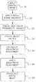
- FIG. 1is a block diagram of a digital image processing system incorporating the present invention
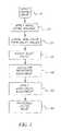
- FIG. 2is a block diagram of the main subject skin region detection
- FIG. 3 ais a graphical illustration of the probability density function of the main subject when image orientation is unknown
- FIG. 3 bis the counterpart when the image orientation is known to be upright
- FIG. 4is a block diagram of the determination of the adaptive threshold in the preferred embodiment of the present invention.
- FIG. 5is a block diagram of the determination of the main subject skin belief map
- FIG. 6is a graphical example of a main subject skin belief map
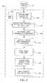
- FIG. 7is a block diagram of determination of a brightness adjustment amount according to the present invention.
- FIG. 8is a graphical example of the Bayes network according to one embodiment of the present invention.
- the computer programmay be stored on a computer readable storage medium, which may comprise, for example; magnetic storage media such as a magnetic disk (e.g., a hard drive or a floppy disk) or magnetic tape; optical storage media such as an optical disc, optical tape, or machine readable bar code; solid state electronic storage devices such as random access memory (RAM), or read only memory (ROM); or any other physical device or medium employed to store a computer program.
- a computer readable storage mediummay comprise, for example; magnetic storage media such as a magnetic disk (e.g., a hard drive or a floppy disk) or magnetic tape; optical storage media such as an optical disc, optical tape, or machine readable bar code; solid state electronic storage devices such as random access memory (RAM), or read only memory (ROM); or any other physical device or medium employed to store a computer program.
- the present inventionis preferably utilized on any well-known computer system, such as a personal computer, handheld computing device or otherwise and/or an apparatus incorporating a processor for image processing. Consequently, the computer system will not be discussed in detail herein.
- the imagesare either directly input into the computer system (for example, by a digital camera) or digitized before input into the computer system (for example, by scanning an original image, such as a silver halide film).
- the processed digital imagescan be printed, for example, on photographic paper by a scanning photographic printer to yield an image having improved overall brightness.
- exemplary contexts and environmentsinclude, without limitation, wholesale digital photofinishing (which involves exemplary process steps or stages such as film in, digital processing, prints out), retail digital photofinishing (film in, digital processing, prints out), home printing (home scanned film or digital images, digital processing, prints out), desktop software (software that applies algorithms to digital prints to make them better -or even just to change them), digital fulfillment (digital images in from media or over the web, digital processing with images out in digital form on media, digital form over the web, or printed on hard-copy prints), kiosks (digital or scanned input, digital processing, digital or scanned output), mobile devices (e.g., PDA or cellphone that can be used as a processing unit, a display unit, or a unit to give processing instructions), and as a service offered via the World Wide Web or Internet.
- wholesale digital photofinishingwhich involves exemplary process steps or stages such as film in, digital processing, prints out
- retail digital photofinishingfilm in, digital processing, prints out
- home printinghome scanned film or digital images, digital processing,
- the algorithmmay stand alone or may be a component of a larger system solution.
- the interfaces with the algorithme.g., the scanning or input, the digital processing, the display to a user (if needed), the input of user requests or processing instructions (if needed), the output, can each be on the same or different devices and physical locations, and communication between the devices and locations can be via public or private network connections, or media based communication.
- the algorithm(s) themselvescan be fully automatic, may have user input (be fully or partially manual), may have user or operator review to accept/reject the result, or may be assisted by metadata (metadata that may be user supplied, supplied by a measuring device (e.g. in a camera), or determined by an algorithm).
- the algorithm(s)may interface with a variety of workflow user interface schemes.
- the skin-colored pixelsare detected using an adaptive threshold technique.
- a digital imageis optionally processed 10 by an initial scene balance algorithm 20 .
- the initial scene balance algorithmcan be any of the known scene balance algorithms, such as the Evans gray world algorithm, the LATD brightness algorithm, the Kwon color scene balance algorithm, or any other scene balance algorithm.
- pixels in the digital imageare initially assigned skin probability values 25 and belief values 30 .
- a brightness adjustment amountis calculated 40 based on the pixels with belief values exceeding a threshold and their belief values 30 .
- the brightness adjustmentis applied 50 to the digital image to produce a processed digital image 60 that has improved brightness balance.
- the step of assigning belief values 30is more completely described with reference to FIG. 2 .
- the probability that it is a skin pixelis computed 130 .
- the skin pixel probability 130is derived from its coordinates in the Lst space, based on skin probability density functions 125 stored in the algorithm.
- These skin probability density functions 125were constructed based on a collection of data for the color-space distributions of skin and non-skin regions in a large collection of scene balanced images.
- the conditional probability that a pixel is a skin pixel given its Lst coordinatesis: Pr (Skin
- L,s,t )Pr (Skin
- the conditional probability that a pixel is a skin pixel given its Lst coordinatesis Pr(Skin
- L,s,t)directly, or the fully decomposed form of Equation 4, or a partially decomposed form of: Pr (Skin
- L,s,t )Pr (Skin
- the collection of probabilities for all pixelsforms a skin probability distribution for the input image.
- the skin probability distributionis thresholded to create a binary map such that each pixel is designated as either skin or non-skin.
- the thresholdingis accomplished using an image-dependent adaptive thresholding algorithm, such that a skin probability threshold 140 is customized for the particular image.
- a fixed thresholdis used for all input images.
- the major drawback of a fixed thresholdis the ignorance of the changing statistics in individual images due to changes in image content and imaging condition.
- Pixels with higher probability than the thresholdare identified 150 as skin pixels while all others are considered non-skin pixels. Labeling the pixels of the cropped image as skin or non-skin produces a binary skin color pixel map 160 for the image.
- the skin color pixel mapis further processed to assign main subject skin belief values 170 and produce a main subject skin belief map 180 .
- contiguous regions of skin color pixelsneed to be extracted using a connected component labeling process, as described in Sonka, Hlavac, and Boyle, Image Processing, Analysis, and Machine Vision , Brooks & Cole, 1999. Each spatially connected region will be treated as an entity in further analysis that produces an indication of how likely it corresponds to a main human subject in the image.
- the determination of the adaptive skin probability threshold 140is more completely described in FIG. 4 .
- a skin probability mapis produced 310 where the value of each pixel represents the corresponding skin probability.
- the gradient of the skin probability mapis computed 320 .
- the gradient of an image f(x,y) at location (x,y)is defined as
- G x[ 1 0 - 1 2 0 - 2 1 0 - 1 ]
- G y[ 1 0 - 1 2 0 - 2 1 0 - 1 ] ( Equation ⁇ ⁇ 6 )
- a maskis generated 330 to indicate those pixels having gradient magnitude values greater than 400.
- a histogram of skin probability valuesis constructed 340 using only those pixels with high gradient values.
- the main advantage of using only the pixels with high gradient valuesis that they generally correspond to the pixels around boundaries of skin regions. Consequently, the histogram generally exhibits distinctive peaks and valleys because the pixels around skin region boundaries have either high or low skin probability values.
- the histogramis further smoothed 350 to reduce the effect of noise.
- a salient valleyis located 360 between two peaks, starting from the low end of the histogram. The location of this valley identifies a skin probability threshold 370 for the given image.
- spatially contiguous regions of skin color pixelsare extracted 550 using connected component labeling from the skin color pixel map 160 for assigning main subject skin belief values 170 , as shown in FIG. 2 .
- the regionsare assigned main subject skin belief values 560 based on a plurality of complementary types of geometric features, including centrality, borderness, and shape. These features are computed in step 555 .
- the evidences from these types of geometric features for each region, as well as the average skin probability value of each region,are integrated using a Bayes net-based reasoning engine 570 to yield a final main subject skin belief map 180 indicating how likely a region of concern corresponds to primary skin regions of the main human subjects, e.g., faces, in the picture.
- Bayes net 570has a structure as illustrated in FIG. 8 .
- training of the Bayes netis done using a combination of expert knowledge and actual data to arrive at a set of proper parameters, i.e., conditional probability matrices.
- Alternative reasoning enginessuch as a neural network or a rule-based network can be used in place of a Bayes network.
- centralityIn terms of location, the main human subject tends to be located near the center instead of the periphery of the image, therefore, a high degree of centrality is indicative that a region is a main subject of an image. However, centrality does not necessarily mean a region is directly in the center of the image. In fact, professional photographers tend to position the main subject along lines and intersections of lines that divide an image into thirds, the so-called gold-partition positions or rule of thirds.
- the centrality measureis defined by computing the integral of a probability density function (PDF) over the area of a given region.
- PDFprobability density function
- the PDFis derived from the “ground truth” data, in which the main subject regions are manually outlined and marked by a value of one and the background regions are marked by a value of zero, by summing the ground truth maps over an entire training set. In essence, the PDF represents the distribution of main subjects in terms of location.
- the centrality measureis devised such that every pixel of a given region, not just the centroid, contributes to the centrality measure of the region to a varying degree depending on its location.
- the centrality measureis defined as:
- the PDFis symmetric about the center of the image in both vertical and horizontal directions, which results in an orientation-independent centrality measure.
- the shape of this PDFis such that objects located in the center of an image are more likely to be the main subject, as illustrated in FIG. 3 a .
- the PDFis symmetric about the center of the image in the horizontal direction but not in the vertical direction, as illustrated in FIG. 3 b , which results in an orientation-dependent centrality measure.
- the shape of this orientation-aware PDFis such that objects located in the bottom portion of an image are more likely to be the main subject.
- bordernessAnother geometric feature is borderness. Many background regions tend to contact one or more of the image borders. Therefore, a region that has significant amount of its contour on the image borders is more likely to belong to the background than to the main subject.
- Two measuresare used to characterize the borderness of a region. They include the number of image borders that a region intersects (hereinafter “borderness 1 ”) and the percentage of a region's perimeter along the image borders (hereinafter “borderness 2 ”).
- borderness 1is used to place a given region into one of six categories. This is determined by the number and configuration of image borders that the region is in contact with. A region is in contact with a border when at least one pixel in the region falls within a fixed distance of the border of the image. Distance is expressed as a fraction of the shorter dimension of the image.
- the six categories for borderness 1are: none, one border, two borders, two facing borders, three borders, and four borders that the region contacts. The more contact a region has with a border increases the likelihood that the region is not a main subject.
- the borderness featurecan be redefined to account for the fact that a region that is in contact with the top border is much more likely to be background than a region that is in contact with the bottom border. This results in twelve categories for borderness 1 , determined by the number and configuration of image borders that the region is in contact with. Using the definition of “in contact with” from above, the four borders of the image are labeled as “Top,” “Bottom,” “Left,” and “Right” according to their position when the image is oriented with objects in the scene standing upright.
- Yet another geometric featureis shape.
- Many background regionseven though they may be skin-colored, may have a shape that is either extremely elongated (e.g., wood rails) or of extremely complicated shape, while in comparison a face tends to be of a simple, slightly elliptical shape. Therefore, a region that has an extremely high aspect ratio or an extremely low compactness measure is most likely to belong to the background than to the main subject.
- two measuresare used to characterize the shape of a region.
- Aspect ratio(length of the long axis of the minimum bounding box)/(length of the short axis of the bounding box) (Equation 10) where the minimum bounding box is the smallest rectangle aligned along the long axis of the region and encompassing the region.
- Compactness(perimeter of a region)*(perimeter of a region)/(area of a region)/4 /Pi (Equation 11)
- the shape featuresare further modified such that they represent a belief value with a maximum value of 1.0, e.g.:
- the output of Bayes net-based reasoning engine 570is a main subject skin belief map comprised of belief values indicating skin-colored regions, in terms of location and an assigned belief value, proportional to the belief that the skin-colored region is associated with a main subject having skin pixels and located in the image.
- the main subject skin belief mapmay contain no skin-colored regions at all.
- the belief mapis more than a binary map that only indicates location of the determined skin pixels related to the main subject.
- the associated likelihoodis also attached to each region so that the regions with large belief values correspond to regions with higher confidence, or belief, that it is part of the main subject.
- the two elliptical shaped regions 600 in the belief map of FIG. 6have the highest belief values being part of the main human subjects (faces), while other regions have much lower belief values because they either touch the image borders, are off center, have elongated or complicated shapes, etc. It should be noted that all the skin color pixels within the same spatially contiguous region have the same belief value.
- a binary main subject skin maskcan be readily obtained by using an appropriate threshold on the belief map.
- a minimum threshold of 0.25(out of 1.0) is applied so that any skin color pixels with belief values lower than 0.25 are treated as the background and thus do not affect the calculation of the brightness adjustment amount.
- any region that is smaller than 0.25% of the entire image areais eliminated.
- the rich belief informationmay be very useful for downstream applications. For example, different weighting factors can be assigned to different skin-colored regions (subject matters) in determining the amount of brightness adjustment, as opposed to treating all the remaining skin regions the same way.
- the calculation of the brightness adjustment amount 40(first shown in FIG. 1 ) is more completely described in FIG. 7 .
- the number of skin color pixels labeled in the main subject skin belief map 180is compared 210 to a pre-determined minimum value (e.g. less than 0.5%). If the number of skin-colored pixels is less than the minimum value, the brightness adjustment is set to zero 211 . If more than the minimum number of skin-colored pixels are found 220 , corresponding to the initial scene balanced digital image 20 , a skin pixel statistic, weighted by the belief values, is calculated 230 for the image. The statistic is calculated as:
- SkinStatistic⁇ i ⁇ ⁇ ⁇ j ⁇ ⁇ L ⁇ ( i , j ) * W ⁇ ( i , j ) * S ⁇ ( i , j ) ⁇ i ⁇ ⁇ ⁇ j ⁇ ⁇ W ⁇ ( i , j ) * S ⁇ ( i , j ) ( Equation ⁇ ⁇ 14 )
- L(i,j)refers to the L coordinate value for the pixel in the i-th row and j-th column of the image
- W(i,j)refers to a weight provided by the main subject skin belief map 180 , wherein the highest believed pixels of the image are given the highest weight and other pixels are given lesser weights
- S(i,j)refers to the ( 0 , 1 ) labeling of pixels provided by the main subject skin belief map 180 , wherein 0 indicates non-skin pixels and 1 indicates skin-colored pixels as determined by the minimum belief threshold.
- Equations 14-16A potential problem of Equations 14-16 is that if the highest belief region in the image has a low absolute belief, e.g., 0.30 (>0.25), the normalization process as indicated by the denominator of the equation would make full-strength brightness adjustment based on a number of low belief skin regions. This is an undesirable effect because these equations enforce relative weighting among skin regions of different belief values while largely ignoring the absolute level of the belief values.
- an additional requirementis for the highest belief region to have a belief value higher than 0.80 (out of 1.0). This requirement is tested in step 220 . If the condition is not met, the brightness adjustment is also set to zero 211 .
- B and Aare predetermined constants.
- the value of Ais a reference value related to the typical L coordinate of skin-colored pixels in images of good brightness quality.
- Bshould be between the values 0 and 1, and allows control of the degree of adjustment applied in response to the detected skin-colored pixels.
- the calculated brightness adjustmentis applied 50 to the digital image 10 to produce the output digital image 60 .
- the subject matter of the present inventionrelates to digital image understanding technology, which is understood to mean technology that digitally processes a digital image to recognize and thereby assign useful meaning to human understandable objects, attributes, or conditions and then to utilize the results obtained in the further processing of the digital image.
Landscapes
- Engineering & Computer Science (AREA)
- Multimedia (AREA)
- Signal Processing (AREA)
- Image Processing (AREA)
- Image Analysis (AREA)
- Facsimile Image Signal Circuits (AREA)
- Color Image Communication Systems (AREA)
Abstract
Description
L=(R+G+B)/sqrt(3) (Equation 1)
s=(R−B)/sqrt(2) (Equation 2)
t=(2G−R−B)/sqrt(6) (Equation 3)
For each pixel in the cropped image, the probability that it is a skin pixel is computed130. The
Pr(Skin|L,s,t)=Pr(Skin|L)*Pr(Skin|s)*Pr(Skin|t) (Equation 4)
where each of the conditional distributions Pr(Skin|L),Pr(Skin|s), and Pr(Skin|t) were constructed by application of Bayes Theorem to the original training distributions for skin and non-skin pixels. In comparison, a few conventional methods for detecting skin, e.g., U.S. Pat. Nos. 4,203,671 and 5,781,276 (both referenced above), use the likelihood probability of P(color|Skin) to detect skin pixels. A major drawback of using the likelihood probability, though conveniently obtained, is that the probability distribution of non-skin pixels is not accounted for. Consequently, there is a higher likelihood for false detection.
Pr(Skin|L,s,t)=Pr(Skin|L)*Pr(Skin|s,t) (Equation 4a)
Where Pr(Skin|s,t) represents a non-separable probability density function.
and its digital forms are two separable kernels:
The magnitude of the gradient vector is:
G=[Gx2+Gy2]1/2≈|Gx|+|Gy| (Equation 7)
where (xy) denotes a pixel in the region R, NRis the number of pixels in region R.
Borderness2=(number_of_region_perimeter_pixels_on_image_border)/[2*(height_of_image+width_of_image)] (Equation 9)
Aspect ratio=(length of the long axis of the minimum bounding box)/(length of the short axis of the bounding box) (Equation 10)
where the minimum bounding box is the smallest rectangle aligned along the long axis of the region and encompassing the region.
Compactness=(perimeter of a region)*(perimeter of a region)/(area of a region)/4/Pi (Equation 11)
where L(i,j) refers to the L coordinate value for the pixel in the i-th row and j-th column of the image, W(i,j) refers to a weight provided by the main subject
The following scheme can be used to de-emphasize large skin regions to such an extent that each region (uniquely identified by a belief value t) gets a vote regardless of its size:
brightness adjustment=B(SkinStatistic−A) (Equation 17)
where B and A are predetermined constants. The value of A is a reference value related to the typical L coordinate of skin-colored pixels in images of good brightness quality. The value of B should be between the
brightness adjustment=f(SkinStatistic) (Equation 17a)
where f( ) is a nonlinear function such as a power function.
- 10 input digital image operation
- 20 scene balance algorithm operation
- 25 assign skin probability operation
- 30 assign belief values operation
- 40 calculate brightness adjustment operation
- 50 apply brightness adjustment operation
- 60 processed digital image operation
- 120 convert to Lst coordinates operation
- 125 skin probability density function operation
- 130 compute skin pixel probability operation
- 140 skin probability threshold operation
- 150 identify skin pixels operation
- 160 binary skin color pixel map operation
- 170 assign main subject skin belief values operation
- 180 main subject skin belief map operation
- 210 compare number of skin pixels operation
- 211 set brightness adjustment to zero operation
- 220 compare the highest belief value to a threshold operation
- 230 calculate skin pixel statistic operation
- 240 calculate brightness adjustment value operation
- 310 produce skin probability map operation
- 320 compute gradient of skin probability map operation
- 330 generate mask operation
- 340 construct histogram operation
- 350 smooth histogram operation
- 360 locate first salient valley operation
- 370 skin probability threshold operation
- 550 extract contiguous skin regions operation
- 555 compute geometric features operation
- 560 assign main subject skin belief values operation
- 570 Bayes network operation
- 600 main subject skin regions
Claims (21)
Priority Applications (4)
| Application Number | Priority Date | Filing Date | Title |
|---|---|---|---|
| US10/426,592US7609908B2 (en) | 2003-04-30 | 2003-04-30 | Method for adjusting the brightness of a digital image utilizing belief values |
| PCT/US2004/011185WO2004100531A1 (en) | 2003-04-30 | 2004-04-12 | Adjusting the brightness of a digital image |
| JP2006509919AJP2007534179A (en) | 2003-04-30 | 2004-04-12 | Adjusting the brightness of digital images |
| EP04760532AEP1618739A1 (en) | 2003-04-30 | 2004-04-12 | Adjusting the brightness of a digital image |
Applications Claiming Priority (1)
| Application Number | Priority Date | Filing Date | Title |
|---|---|---|---|
| US10/426,592US7609908B2 (en) | 2003-04-30 | 2003-04-30 | Method for adjusting the brightness of a digital image utilizing belief values |
Publications (2)
| Publication Number | Publication Date |
|---|---|
| US20040218832A1 US20040218832A1 (en) | 2004-11-04 |
| US7609908B2true US7609908B2 (en) | 2009-10-27 |
Family
ID=33309906
Family Applications (1)
| Application Number | Title | Priority Date | Filing Date |
|---|---|---|---|
| US10/426,592Expired - Fee RelatedUS7609908B2 (en) | 2003-04-30 | 2003-04-30 | Method for adjusting the brightness of a digital image utilizing belief values |
Country Status (4)
| Country | Link |
|---|---|
| US (1) | US7609908B2 (en) |
| EP (1) | EP1618739A1 (en) |
| JP (1) | JP2007534179A (en) |
| WO (1) | WO2004100531A1 (en) |
Cited By (12)
| Publication number | Priority date | Publication date | Assignee | Title |
|---|---|---|---|---|
| US20080089583A1 (en)* | 2003-05-19 | 2008-04-17 | Stmicroelectronics S.R.L. | Digital image processing method having an exposure correction based on recognition of areas corresponding to the skin of the photographed subject |
| US20080298704A1 (en)* | 2007-05-29 | 2008-12-04 | Hila Nachlieli | Face and skin sensitive image enhancement |
| US20100098323A1 (en)* | 2008-07-18 | 2010-04-22 | Agrawal Amit K | Method and Apparatus for Determining 3D Shapes of Objects |
| US20120176395A1 (en)* | 2011-01-06 | 2012-07-12 | Ya-Ti Peng | System, method and computer program product for color processing of point-of-interest color |
| US8441548B1 (en)* | 2012-06-15 | 2013-05-14 | Google Inc. | Facial image quality assessment |
| US8494263B2 (en)* | 2006-03-20 | 2013-07-23 | Accenture Global Services Limited | Image processing system for skin detection and localization |
| US20130194424A1 (en)* | 2012-01-30 | 2013-08-01 | Clarion Co., Ltd. | Exposure controller for on-vehicle camera |
| US20150243049A1 (en)* | 2012-10-22 | 2015-08-27 | Nokia Technologies Oy | Classifying image samples |
| US9251574B2 (en)* | 2013-12-17 | 2016-02-02 | Adobe Systems Incorporated | Image compensation value computation |
| US11257189B2 (en) | 2019-05-02 | 2022-02-22 | Samsung Electronics Co., Ltd. | Electronic apparatus and image processing method thereof |
| US11373280B2 (en) | 2019-05-16 | 2022-06-28 | Samsung Electronics Co., Ltd. | Electronic device and method of training a learning model for contrast ratio of an image |
| US11772561B1 (en)* | 2022-04-07 | 2023-10-03 | GM Global Technology Operations LLC | Digital flashlight to help hitching and other maneuvers in dim environment |
Families Citing this family (55)
| Publication number | Priority date | Publication date | Assignee | Title |
|---|---|---|---|---|
| US8494286B2 (en) | 2008-02-05 | 2013-07-23 | DigitalOptics Corporation Europe Limited | Face detection in mid-shot digital images |
| US8948468B2 (en)* | 2003-06-26 | 2015-02-03 | Fotonation Limited | Modification of viewing parameters for digital images using face detection information |
| US8155397B2 (en) | 2007-09-26 | 2012-04-10 | DigitalOptics Corporation Europe Limited | Face tracking in a camera processor |
| US7792970B2 (en) | 2005-06-17 | 2010-09-07 | Fotonation Vision Limited | Method for establishing a paired connection between media devices |
| US7844076B2 (en) | 2003-06-26 | 2010-11-30 | Fotonation Vision Limited | Digital image processing using face detection and skin tone information |
| US8330831B2 (en) | 2003-08-05 | 2012-12-11 | DigitalOptics Corporation Europe Limited | Method of gathering visual meta data using a reference image |
| US7616233B2 (en) | 2003-06-26 | 2009-11-10 | Fotonation Vision Limited | Perfecting of digital image capture parameters within acquisition devices using face detection |
| US7269292B2 (en) | 2003-06-26 | 2007-09-11 | Fotonation Vision Limited | Digital image adjustable compression and resolution using face detection information |
| US8896725B2 (en) | 2007-06-21 | 2014-11-25 | Fotonation Limited | Image capture device with contemporaneous reference image capture mechanism |
| US9692964B2 (en) | 2003-06-26 | 2017-06-27 | Fotonation Limited | Modification of post-viewing parameters for digital images using image region or feature information |
| US8593542B2 (en) | 2005-12-27 | 2013-11-26 | DigitalOptics Corporation Europe Limited | Foreground/background separation using reference images |
| US7440593B1 (en) | 2003-06-26 | 2008-10-21 | Fotonation Vision Limited | Method of improving orientation and color balance of digital images using face detection information |
| US7574016B2 (en) | 2003-06-26 | 2009-08-11 | Fotonation Vision Limited | Digital image processing using face detection information |
| US7471846B2 (en) | 2003-06-26 | 2008-12-30 | Fotonation Vision Limited | Perfecting the effect of flash within an image acquisition devices using face detection |
| US7620218B2 (en) | 2006-08-11 | 2009-11-17 | Fotonation Ireland Limited | Real-time face tracking with reference images |
| US8682097B2 (en) | 2006-02-14 | 2014-03-25 | DigitalOptics Corporation Europe Limited | Digital image enhancement with reference images |
| US8989453B2 (en) | 2003-06-26 | 2015-03-24 | Fotonation Limited | Digital image processing using face detection information |
| US7565030B2 (en) | 2003-06-26 | 2009-07-21 | Fotonation Vision Limited | Detecting orientation of digital images using face detection information |
| US9129381B2 (en) | 2003-06-26 | 2015-09-08 | Fotonation Limited | Modification of post-viewing parameters for digital images using image region or feature information |
| US8498452B2 (en) | 2003-06-26 | 2013-07-30 | DigitalOptics Corporation Europe Limited | Digital image processing using face detection information |
| US7440862B2 (en)* | 2004-05-10 | 2008-10-21 | Agilent Technologies, Inc. | Combining multiple independent sources of information for classification of devices under test |
| US8320641B2 (en) | 2004-10-28 | 2012-11-27 | DigitalOptics Corporation Europe Limited | Method and apparatus for red-eye detection using preview or other reference images |
| US8503800B2 (en) | 2007-03-05 | 2013-08-06 | DigitalOptics Corporation Europe Limited | Illumination detection using classifier chains |
| US7315631B1 (en) | 2006-08-11 | 2008-01-01 | Fotonation Vision Limited | Real-time face tracking in a digital image acquisition device |
| US7936919B2 (en)* | 2005-01-18 | 2011-05-03 | Fujifilm Corporation | Correction of color balance of face images depending upon whether image is color or monochrome |
| JP4594225B2 (en)* | 2005-01-18 | 2010-12-08 | 富士フイルム株式会社 | Image correction apparatus and method, and image correction program |
| JP4718952B2 (en)* | 2005-09-27 | 2011-07-06 | 富士フイルム株式会社 | Image correction method and image correction system |
| JP2007193729A (en)* | 2006-01-23 | 2007-08-02 | Seiko Epson Corp | Printing apparatus, image processing apparatus, printing method, and image processing method |
| JP2007219815A (en)* | 2006-02-16 | 2007-08-30 | Seiko Epson Corp | Printing apparatus, image processing apparatus, printing method, and image processing method |
| EP2033142B1 (en) | 2006-06-12 | 2011-01-26 | Tessera Technologies Ireland Limited | Advances in extending the aam techniques from grayscale to color images |
| JP2008022240A (en)* | 2006-07-12 | 2008-01-31 | Fujifilm Corp | Imaging device, image processing device, image file generation method, image processing method, and image processing program |
| US20080019575A1 (en)* | 2006-07-20 | 2008-01-24 | Anthony Scalise | Digital image cropping using a blended map |
| US20080019574A1 (en)* | 2006-07-20 | 2008-01-24 | Anthony Scalise | Machine-controlled image cropping with default |
| US7916897B2 (en) | 2006-08-11 | 2011-03-29 | Tessera Technologies Ireland Limited | Face tracking for controlling imaging parameters |
| US7403643B2 (en) | 2006-08-11 | 2008-07-22 | Fotonation Vision Limited | Real-time face tracking in a digital image acquisition device |
| US20080181534A1 (en)* | 2006-12-18 | 2008-07-31 | Masanori Toyoda | Image processing method, image processing apparatus, image reading apparatus, image forming apparatus and recording medium |
| US8055067B2 (en) | 2007-01-18 | 2011-11-08 | DigitalOptics Corporation Europe Limited | Color segmentation |
| JP5049356B2 (en) | 2007-02-28 | 2012-10-17 | デジタルオプティックス・コーポレイション・ヨーロッパ・リミテッド | Separation of directional lighting variability in statistical face modeling based on texture space decomposition |
| JP4970557B2 (en) | 2007-03-05 | 2012-07-11 | デジタルオプティックス・コーポレイション・ヨーロッパ・リミテッド | Face search and detection in digital image capture device |
| JP4848521B2 (en)* | 2007-03-29 | 2011-12-28 | 国立大学法人九州工業大学 | Method for substituting mouse for projector projected image and system for substituting mouse for the same |
| US7916971B2 (en) | 2007-05-24 | 2011-03-29 | Tessera Technologies Ireland Limited | Image processing method and apparatus |
| US7855737B2 (en) | 2008-03-26 | 2010-12-21 | Fotonation Ireland Limited | Method of making a digital camera image of a scene including the camera user |
| CN102027505A (en) | 2008-07-30 | 2011-04-20 | 泰塞拉技术爱尔兰公司 | Automatic face and skin retouching using face detection |
| KR101549824B1 (en)* | 2008-12-11 | 2015-09-03 | 삼성전자주식회사 | Method and apparatus for correcting skin color and digital photographing apparatus using thereof |
| US8379917B2 (en) | 2009-10-02 | 2013-02-19 | DigitalOptics Corporation Europe Limited | Face recognition performance using additional image features |
| KR101408365B1 (en) | 2012-11-02 | 2014-06-18 | 삼성테크윈 주식회사 | Apparatus and method for analyzing image |
| CN104200211A (en)* | 2014-09-03 | 2014-12-10 | 腾讯科技(深圳)有限公司 | Image binaryzation method and device |
| US11743402B2 (en)* | 2015-02-13 | 2023-08-29 | Awes.Me, Inc. | System and method for photo subject display optimization |
| CN106611429B (en)* | 2015-10-26 | 2019-02-05 | 腾讯科技(深圳)有限公司 | Detect the method for skin area and the device of detection skin area |
| CN105654469B (en)* | 2015-12-22 | 2018-11-16 | 深圳贝申医疗技术有限公司 | A kind of automatic analysis method and system of baby stool color |
| US10997700B2 (en) | 2017-12-29 | 2021-05-04 | Idemia Identity & Security USA LLC | System and method for normalizing skin tone brightness in a portrait image |
| CN109948476B (en)* | 2019-03-06 | 2022-12-13 | 南京七奇智能科技有限公司 | Human face skin detection system based on computer vision and implementation method thereof |
| JP7683487B2 (en) | 2019-12-27 | 2025-05-27 | 株式会社ソシオネクスト | Image processing device and image processing method |
| US11508071B2 (en)* | 2020-09-17 | 2022-11-22 | Xerox Corporation | System and method to detect, suppress, and modify background regions of scanned documents |
| EP4622245A1 (en)* | 2024-03-22 | 2025-09-24 | INTEL Corporation | Personalized skin tone adaptation for images and video |
Citations (17)
| Publication number | Priority date | Publication date | Assignee | Title |
|---|---|---|---|---|
| US2571697A (en)* | 1946-06-20 | 1951-10-16 | Eastman Kodak Co | Method for correcting photographic color prints |
| US4203671A (en) | 1976-06-22 | 1980-05-20 | Fuji Photo Film Co., Ltd. | Method of detecting flesh color in color originals |
| US5130935A (en)* | 1986-03-31 | 1992-07-14 | Canon Kabushiki Kaisha | Color image processing apparatus for extracting image data having predetermined color information from among inputted image data and for correcting inputted image data in response to the extracted image data |
| US5293427A (en)* | 1990-12-14 | 1994-03-08 | Nissan Motor Company, Ltd. | Eye position detecting system and method therefor |
| US5781276A (en) | 1992-07-27 | 1998-07-14 | Agfa-Gevaert Ag | Printing of color film |
| US5959720A (en)* | 1996-03-22 | 1999-09-28 | Eastman Kodak Company | Method for color balance determination |
| US6236736B1 (en)* | 1997-02-07 | 2001-05-22 | Ncr Corporation | Method and apparatus for detecting movement patterns at a self-service checkout terminal |
| US6377702B1 (en)* | 1999-12-08 | 2002-04-23 | Sony Corporation | Color cast detection and removal in digital images |
| US20020136452A1 (en)* | 2001-02-09 | 2002-09-26 | Michael Schroder | Method and device for the correction of colors of photographic images |
| US20020136454A1 (en)* | 2000-10-21 | 2002-09-26 | Soo-Jun Park | Non-linear quantization and similarity matching methods for retrieving image data |
| US6473198B1 (en) | 1997-09-19 | 2002-10-29 | Fuji Photo Film Co., Ltd. | Image processing apparatus |
| US20030012414A1 (en)* | 2001-06-29 | 2003-01-16 | Huitao Luo | Automatic digital image enhancement |
| US20030035578A1 (en) | 2001-07-12 | 2003-02-20 | Eastman Kodak Company | Method for processing a digital image to adjust brightness |
| US6700999B1 (en)* | 2000-06-30 | 2004-03-02 | Intel Corporation | System, method, and apparatus for multiple face tracking |
| US6933970B2 (en)* | 1999-12-20 | 2005-08-23 | Texas Instruments Incorporated | Digital still camera system and method |
| US7035456B2 (en)* | 2001-06-01 | 2006-04-25 | Canon Kabushiki Kaisha | Face detection in color images with complex background |
| US7106887B2 (en)* | 2000-04-13 | 2006-09-12 | Fuji Photo Film Co., Ltd. | Image processing method using conditions corresponding to an identified person |
- 2003
- 2003-04-30USUS10/426,592patent/US7609908B2/ennot_activeExpired - Fee Related
- 2004
- 2004-04-12EPEP04760532Apatent/EP1618739A1/ennot_activeWithdrawn
- 2004-04-12WOPCT/US2004/011185patent/WO2004100531A1/ennot_activeApplication Discontinuation
- 2004-04-12JPJP2006509919Apatent/JP2007534179A/enactivePending
Patent Citations (17)
| Publication number | Priority date | Publication date | Assignee | Title |
|---|---|---|---|---|
| US2571697A (en)* | 1946-06-20 | 1951-10-16 | Eastman Kodak Co | Method for correcting photographic color prints |
| US4203671A (en) | 1976-06-22 | 1980-05-20 | Fuji Photo Film Co., Ltd. | Method of detecting flesh color in color originals |
| US5130935A (en)* | 1986-03-31 | 1992-07-14 | Canon Kabushiki Kaisha | Color image processing apparatus for extracting image data having predetermined color information from among inputted image data and for correcting inputted image data in response to the extracted image data |
| US5293427A (en)* | 1990-12-14 | 1994-03-08 | Nissan Motor Company, Ltd. | Eye position detecting system and method therefor |
| US5781276A (en) | 1992-07-27 | 1998-07-14 | Agfa-Gevaert Ag | Printing of color film |
| US5959720A (en)* | 1996-03-22 | 1999-09-28 | Eastman Kodak Company | Method for color balance determination |
| US6236736B1 (en)* | 1997-02-07 | 2001-05-22 | Ncr Corporation | Method and apparatus for detecting movement patterns at a self-service checkout terminal |
| US6473198B1 (en) | 1997-09-19 | 2002-10-29 | Fuji Photo Film Co., Ltd. | Image processing apparatus |
| US6377702B1 (en)* | 1999-12-08 | 2002-04-23 | Sony Corporation | Color cast detection and removal in digital images |
| US6933970B2 (en)* | 1999-12-20 | 2005-08-23 | Texas Instruments Incorporated | Digital still camera system and method |
| US7106887B2 (en)* | 2000-04-13 | 2006-09-12 | Fuji Photo Film Co., Ltd. | Image processing method using conditions corresponding to an identified person |
| US6700999B1 (en)* | 2000-06-30 | 2004-03-02 | Intel Corporation | System, method, and apparatus for multiple face tracking |
| US20020136454A1 (en)* | 2000-10-21 | 2002-09-26 | Soo-Jun Park | Non-linear quantization and similarity matching methods for retrieving image data |
| US20020136452A1 (en)* | 2001-02-09 | 2002-09-26 | Michael Schroder | Method and device for the correction of colors of photographic images |
| US7035456B2 (en)* | 2001-06-01 | 2006-04-25 | Canon Kabushiki Kaisha | Face detection in color images with complex background |
| US20030012414A1 (en)* | 2001-06-29 | 2003-01-16 | Huitao Luo | Automatic digital image enhancement |
| US20030035578A1 (en) | 2001-07-12 | 2003-02-20 | Eastman Kodak Company | Method for processing a digital image to adjust brightness |
Non-Patent Citations (5)
| Title |
|---|
| "A Skin Probability Map and its Use in Face Detection" by J.D. Brand and Dr. J.S.D. Mason. Proceedings 2001 International Conference on Image Processing, ICIP 2001. Thessaloniki, Greece, Oct. 7-10, 2001, International Conference on Image Processing, New York, NY, IEEE, US, vol. 1 of 3, Conf. 8, Oct. 7, 2001, pp. 1034-1037. |
| "Combination of high-level cues in unsupervised single image segmentation using Bayesian Belief Networks" by Pablo Alvarado, Axel Berner, Suat Akyol. Proceedings of the International Conference on Imaging Science, Systems, and Technology, vol. 2, Jun. 27, 2002, pp. 675-681. |
| "On Selecting Colour Components for Skin Detection" by Giovani Gomez. Pattern Recognition, 2002. Proceedings of the 16th International Conference on Quebec City, Quebec, Canada, Aug. 11-15, 2002, Los Alamitos, CA, USA, IEEE Computer Soc., US, Aug. 11, 2002, pp. 961-964. |
| "Statistical Color Models with Application to Skin Detection" by Michael J. Jones and James M. Rehg. International Journal of Computer Vision, vol. 46, No. 1, 2002, pp. 81-96, Int. J. Comput. Vis. (Netherlands), Kluwer Academic Publishers, Netherlands. |
| E. Goll et al., "Modern Exposure Determination For Customizing Photofinishing Printer Response," Journal of Applied Photographic Engineering, vol. 5, No. 2, Spring 1979, pp. 93-104. |
Cited By (23)
| Publication number | Priority date | Publication date | Assignee | Title |
|---|---|---|---|---|
| US7778483B2 (en)* | 2003-05-19 | 2010-08-17 | Stmicroelectronics S.R.L. | Digital image processing method having an exposure correction based on recognition of areas corresponding to the skin of the photographed subject |
| US20080089583A1 (en)* | 2003-05-19 | 2008-04-17 | Stmicroelectronics S.R.L. | Digital image processing method having an exposure correction based on recognition of areas corresponding to the skin of the photographed subject |
| US8494263B2 (en)* | 2006-03-20 | 2013-07-23 | Accenture Global Services Limited | Image processing system for skin detection and localization |
| US20080298704A1 (en)* | 2007-05-29 | 2008-12-04 | Hila Nachlieli | Face and skin sensitive image enhancement |
| US8031961B2 (en)* | 2007-05-29 | 2011-10-04 | Hewlett-Packard Development Company, L.P. | Face and skin sensitive image enhancement |
| US20100098323A1 (en)* | 2008-07-18 | 2010-04-22 | Agrawal Amit K | Method and Apparatus for Determining 3D Shapes of Objects |
| US20120176395A1 (en)* | 2011-01-06 | 2012-07-12 | Ya-Ti Peng | System, method and computer program product for color processing of point-of-interest color |
| TWI507043B (en)* | 2011-01-06 | 2015-11-01 | Intel Corp | System, method and computer program product for color processing of point-of-interest color |
| US8493402B2 (en)* | 2011-01-06 | 2013-07-23 | Intel Corporation | System, method and computer program product for color processing of point-of-interest color |
| US9118838B2 (en)* | 2012-01-30 | 2015-08-25 | Clarion Co., Ltd. | Exposure controller for on-vehicle camera |
| US20130194424A1 (en)* | 2012-01-30 | 2013-08-01 | Clarion Co., Ltd. | Exposure controller for on-vehicle camera |
| US20130336527A1 (en)* | 2012-06-15 | 2013-12-19 | Google Inc. | Facial image quality assessment |
| US9047538B2 (en)* | 2012-06-15 | 2015-06-02 | Google Inc. | Facial image quality assessment |
| US8441548B1 (en)* | 2012-06-15 | 2013-05-14 | Google Inc. | Facial image quality assessment |
| US20150243049A1 (en)* | 2012-10-22 | 2015-08-27 | Nokia Technologies Oy | Classifying image samples |
| US10096127B2 (en)* | 2012-10-22 | 2018-10-09 | Nokia Technologies Oy | Classifying image samples |
| US9251574B2 (en)* | 2013-12-17 | 2016-02-02 | Adobe Systems Incorporated | Image compensation value computation |
| US9633421B2 (en) | 2013-12-17 | 2017-04-25 | Adobe Systems Incorporated | Image compensation value computation |
| US11257189B2 (en) | 2019-05-02 | 2022-02-22 | Samsung Electronics Co., Ltd. | Electronic apparatus and image processing method thereof |
| US11861809B2 (en) | 2019-05-02 | 2024-01-02 | Samsung Electronics Co., Ltd. | Electronic apparatus and image processing method thereof |
| US11373280B2 (en) | 2019-05-16 | 2022-06-28 | Samsung Electronics Co., Ltd. | Electronic device and method of training a learning model for contrast ratio of an image |
| US11772561B1 (en)* | 2022-04-07 | 2023-10-03 | GM Global Technology Operations LLC | Digital flashlight to help hitching and other maneuvers in dim environment |
| US20230322159A1 (en)* | 2022-04-07 | 2023-10-12 | GM Global Technology Operations LLC | Digital flashlight to help hitching and other maneuvers in dim environment |
Also Published As
| Publication number | Publication date |
|---|---|
| US20040218832A1 (en) | 2004-11-04 |
| JP2007534179A (en) | 2007-11-22 |
| EP1618739A1 (en) | 2006-01-25 |
| WO2004100531A1 (en) | 2004-11-18 |
Similar Documents
| Publication | Publication Date | Title |
|---|---|---|
| US7609908B2 (en) | Method for adjusting the brightness of a digital image utilizing belief values | |
| US6845181B2 (en) | Method for processing a digital image to adjust brightness | |
| US7171058B2 (en) | Method and computer program product for producing an image of a desired aspect ratio | |
| US7212668B1 (en) | Digital image processing system and method for emphasizing a main subject of an image | |
| US6952286B2 (en) | Doubleprint photofinishing service with the second print having subject content-based modifications | |
| US7289664B2 (en) | Method of detecting and correcting the red eye | |
| US7684642B2 (en) | Correction of redeye defects in images of humans | |
| US7162102B2 (en) | Method and system for compositing images to produce a cropped image | |
| US6654507B2 (en) | Automatically producing an image of a portion of a photographic image | |
| JP4335476B2 (en) | Method for changing the number, size, and magnification of photographic prints based on image saliency and appeal | |
| US8295606B2 (en) | Device and method for detecting shadow in image | |
| US20020135743A1 (en) | Digital image processing method and apparatus for brightness adjustment of digital images | |
| EP1168247A2 (en) | Method for varying an image processing path based on image emphasis and appeal | |
| US20070071316A1 (en) | Image correcting method and image correcting system | |
| JPH0863597A (en) | Face extracting method | |
| CN101322153A (en) | Adjusting digital image exposure and tone scale | |
| US6445831B1 (en) | Image processing method and apparatus | |
| JP3516786B2 (en) | Face area extraction method and copy condition determination method | |
| US20030231324A1 (en) | Image processing method and apparatus | |
| JPH09146194A (en) | Exposure deciding method and exposure controller | |
| JP2005202567A (en) | Image processing method, image processor and image processing program |
Legal Events
| Date | Code | Title | Description |
|---|---|---|---|
| AS | Assignment | Owner name:EASTMAN KODAK COMPANY, NEW YORK Free format text:ASSIGNMENT OF ASSIGNORS INTEREST;ASSIGNORS:LUO, JIEBO;DUPIN, MICHAEL W.;GALLAGHER, ANDREW C.;REEL/FRAME:014032/0797 Effective date:20030429 | |
| FEPP | Fee payment procedure | Free format text:PAYOR NUMBER ASSIGNED (ORIGINAL EVENT CODE: ASPN); ENTITY STATUS OF PATENT OWNER: LARGE ENTITY | |
| STCF | Information on status: patent grant | Free format text:PATENTED CASE | |
| CC | Certificate of correction | ||
| AS | Assignment | Owner name:CITICORP NORTH AMERICA, INC., AS AGENT, NEW YORK Free format text:SECURITY INTEREST;ASSIGNORS:EASTMAN KODAK COMPANY;PAKON, INC.;REEL/FRAME:028201/0420 Effective date:20120215 | |
| FEPP | Fee payment procedure | Free format text:PAYER NUMBER DE-ASSIGNED (ORIGINAL EVENT CODE: RMPN); ENTITY STATUS OF PATENT OWNER: LARGE ENTITY Free format text:PAYOR NUMBER ASSIGNED (ORIGINAL EVENT CODE: ASPN); ENTITY STATUS OF PATENT OWNER: LARGE ENTITY | |
| AS | Assignment | Owner name:CREO MANUFACTURING AMERICA LLC, WYOMING Free format text:PATENT RELEASE;ASSIGNORS:CITICORP NORTH AMERICA, INC.;WILMINGTON TRUST, NATIONAL ASSOCIATION;REEL/FRAME:029913/0001 Effective date:20130201 Owner name:KODAK AMERICAS, LTD., NEW YORK Free format text:PATENT RELEASE;ASSIGNORS:CITICORP NORTH AMERICA, INC.;WILMINGTON TRUST, NATIONAL ASSOCIATION;REEL/FRAME:029913/0001 Effective date:20130201 Owner name:KODAK REALTY, INC., NEW YORK Free format text:PATENT RELEASE;ASSIGNORS:CITICORP NORTH AMERICA, INC.;WILMINGTON TRUST, NATIONAL ASSOCIATION;REEL/FRAME:029913/0001 Effective date:20130201 Owner name:FPC INC., CALIFORNIA Free format text:PATENT RELEASE;ASSIGNORS:CITICORP NORTH AMERICA, INC.;WILMINGTON TRUST, NATIONAL ASSOCIATION;REEL/FRAME:029913/0001 Effective date:20130201 Owner name:PAKON, INC., INDIANA Free format text:PATENT RELEASE;ASSIGNORS:CITICORP NORTH AMERICA, INC.;WILMINGTON TRUST, NATIONAL ASSOCIATION;REEL/FRAME:029913/0001 Effective date:20130201 Owner name:KODAK PHILIPPINES, LTD., NEW YORK Free format text:PATENT RELEASE;ASSIGNORS:CITICORP NORTH AMERICA, INC.;WILMINGTON TRUST, NATIONAL ASSOCIATION;REEL/FRAME:029913/0001 Effective date:20130201 Owner name:FAR EAST DEVELOPMENT LTD., NEW YORK Free format text:PATENT RELEASE;ASSIGNORS:CITICORP NORTH AMERICA, INC.;WILMINGTON TRUST, NATIONAL ASSOCIATION;REEL/FRAME:029913/0001 Effective date:20130201 Owner name:KODAK IMAGING NETWORK, INC., CALIFORNIA Free format text:PATENT RELEASE;ASSIGNORS:CITICORP NORTH AMERICA, INC.;WILMINGTON TRUST, NATIONAL ASSOCIATION;REEL/FRAME:029913/0001 Effective date:20130201 Owner name:QUALEX INC., NORTH CAROLINA Free format text:PATENT RELEASE;ASSIGNORS:CITICORP NORTH AMERICA, INC.;WILMINGTON TRUST, NATIONAL ASSOCIATION;REEL/FRAME:029913/0001 Effective date:20130201 Owner name:EASTMAN KODAK INTERNATIONAL CAPITAL COMPANY, INC., Free format text:PATENT RELEASE;ASSIGNORS:CITICORP NORTH AMERICA, INC.;WILMINGTON TRUST, NATIONAL ASSOCIATION;REEL/FRAME:029913/0001 Effective date:20130201 Owner name:NPEC INC., NEW YORK Free format text:PATENT RELEASE;ASSIGNORS:CITICORP NORTH AMERICA, INC.;WILMINGTON TRUST, NATIONAL ASSOCIATION;REEL/FRAME:029913/0001 Effective date:20130201 Owner name:KODAK AVIATION LEASING LLC, NEW YORK Free format text:PATENT RELEASE;ASSIGNORS:CITICORP NORTH AMERICA, INC.;WILMINGTON TRUST, NATIONAL ASSOCIATION;REEL/FRAME:029913/0001 Effective date:20130201 Owner name:KODAK (NEAR EAST), INC., NEW YORK Free format text:PATENT RELEASE;ASSIGNORS:CITICORP NORTH AMERICA, INC.;WILMINGTON TRUST, NATIONAL ASSOCIATION;REEL/FRAME:029913/0001 Effective date:20130201 Owner name:KODAK PORTUGUESA LIMITED, NEW YORK Free format text:PATENT RELEASE;ASSIGNORS:CITICORP NORTH AMERICA, INC.;WILMINGTON TRUST, NATIONAL ASSOCIATION;REEL/FRAME:029913/0001 Effective date:20130201 Owner name:LASER-PACIFIC MEDIA CORPORATION, NEW YORK Free format text:PATENT RELEASE;ASSIGNORS:CITICORP NORTH AMERICA, INC.;WILMINGTON TRUST, NATIONAL ASSOCIATION;REEL/FRAME:029913/0001 Effective date:20130201 Owner name:EASTMAN KODAK COMPANY, NEW YORK Free format text:PATENT RELEASE;ASSIGNORS:CITICORP NORTH AMERICA, INC.;WILMINGTON TRUST, NATIONAL ASSOCIATION;REEL/FRAME:029913/0001 Effective date:20130201 | |
| FPAY | Fee payment | Year of fee payment:4 | |
| AS | Assignment | Owner name:INTELLECTUAL VENTURES FUND 83 LLC, NEVADA Free format text:ASSIGNMENT OF ASSIGNORS INTEREST;ASSIGNOR:EASTMAN KODAK COMPANY;REEL/FRAME:030215/0289 Effective date:20130201 | |
| AS | Assignment | Owner name:MONUMENT PEAK VENTURES, LLC, TEXAS Free format text:ASSIGNMENT OF ASSIGNORS INTEREST;ASSIGNOR:INTELLECTUAL VENTURES FUND 83 LLC;REEL/FRAME:041941/0079 Effective date:20170215 | |
| REMI | Maintenance fee reminder mailed | ||
| FEPP | Fee payment procedure | Free format text:7.5 YR SURCHARGE - LATE PMT W/IN 6 MO, LARGE ENTITY (ORIGINAL EVENT CODE: M1555) | |
| MAFP | Maintenance fee payment | Free format text:PAYMENT OF MAINTENANCE FEE, 8TH YEAR, LARGE ENTITY (ORIGINAL EVENT CODE: M1552) Year of fee payment:8 | |
| FEPP | Fee payment procedure | Free format text:MAINTENANCE FEE REMINDER MAILED (ORIGINAL EVENT CODE: REM.); ENTITY STATUS OF PATENT OWNER: LARGE ENTITY | |
| LAPS | Lapse for failure to pay maintenance fees | Free format text:PATENT EXPIRED FOR FAILURE TO PAY MAINTENANCE FEES (ORIGINAL EVENT CODE: EXP.); ENTITY STATUS OF PATENT OWNER: LARGE ENTITY | |
| STCH | Information on status: patent discontinuation | Free format text:PATENT EXPIRED DUE TO NONPAYMENT OF MAINTENANCE FEES UNDER 37 CFR 1.362 | |
| FP | Lapsed due to failure to pay maintenance fee | Effective date:20211027 | |
| AS | Assignment | Owner name:MONUMENT PEAK VENTURES, LLC, TEXAS Free format text:RELEASE BY SECURED PARTY;ASSIGNOR:INTELLECTUAL VENTURES FUND 83 LLC;REEL/FRAME:064599/0304 Effective date:20230728 |