US7609561B2 - Disabling faulty flash memory dies - Google Patents
Disabling faulty flash memory diesDownload PDFInfo
- Publication number
- US7609561B2 US7609561B2US11/334,087US33408706AUS7609561B2US 7609561 B2US7609561 B2US 7609561B2US 33408706 AUS33408706 AUS 33408706AUS 7609561 B2US7609561 B2US 7609561B2
- Authority
- US
- United States
- Prior art keywords
- flash memory
- die
- disabling
- identified
- access
- Prior art date
- Legal status (The legal status is an assumption and is not a legal conclusion. Google has not performed a legal analysis and makes no representation as to the accuracy of the status listed.)
- Active, expires
Links
Images


Classifications
- G—PHYSICS
- G11—INFORMATION STORAGE
- G11C—STATIC STORES
- G11C29/00—Checking stores for correct operation ; Subsequent repair; Testing stores during standby or offline operation
- G11C29/70—Masking faults in memories by using spares or by reconfiguring
- G11C29/88—Masking faults in memories by using spares or by reconfiguring with partially good memories
- G11C29/883—Masking faults in memories by using spares or by reconfiguring with partially good memories using a single defective memory device with reduced capacity, e.g. half capacity
- G—PHYSICS
- G11—INFORMATION STORAGE
- G11C—STATIC STORES
- G11C29/00—Checking stores for correct operation ; Subsequent repair; Testing stores during standby or offline operation
- G11C29/70—Masking faults in memories by using spares or by reconfiguring
- G11C29/88—Masking faults in memories by using spares or by reconfiguring with partially good memories
- G—PHYSICS
- G11—INFORMATION STORAGE
- G11C—STATIC STORES
- G11C16/00—Erasable programmable read-only memories
- G11C16/02—Erasable programmable read-only memories electrically programmable
- G11C16/04—Erasable programmable read-only memories electrically programmable using variable threshold transistors, e.g. FAMOS
- G—PHYSICS
- G11—INFORMATION STORAGE
- G11C—STATIC STORES
- G11C29/00—Checking stores for correct operation ; Subsequent repair; Testing stores during standby or offline operation
- G11C29/70—Masking faults in memories by using spares or by reconfiguring
- G11C29/78—Masking faults in memories by using spares or by reconfiguring using programmable devices
- G11C29/83—Masking faults in memories by using spares or by reconfiguring using programmable devices with reduced power consumption
- H—ELECTRICITY
- H01—ELECTRIC ELEMENTS
- H01L—SEMICONDUCTOR DEVICES NOT COVERED BY CLASS H10
- H01L2924/00—Indexing scheme for arrangements or methods for connecting or disconnecting semiconductor or solid-state bodies as covered by H01L24/00
- H01L2924/0001—Technical content checked by a classifier
- H01L2924/0002—Not covered by any one of groups H01L24/00, H01L24/00 and H01L2224/00
Definitions
- Various implementationsmay relate generally to flash memory devices, and particular implementations may relate to methods and systems for disabling faulty dies in flash memory devices.
- Data storage deviceshave been used, for example, to store program instructions (i.e., code) that may be executed by processors.
- Data storage deviceshave also been used to store other types of data, including audio, image, and/or text information, for example.
- Recently, systems with data storage devices capable of storing substantial data contente.g., songs, music videos, etc. . . . ) have become widely available in portable devices.
- Such portable devicesinclude data storage devices that have small form factors and are capable of operating from portable power sources, such as batteries. Some data storage devices in portable devices may provide non-volatile memory that is capable of retaining data when disconnected from the power source. Portable devices have used various non-volatile data storage devices, such as hard disc drives, EEPROM (electrically erasable programmable read only memory), and flash memory.
- Flash memoryhas become a widely used type of semiconductor memory. Flash memory may provide a non-volatile memory in portable electronic devices and consumer applications, for example.
- NOR flashTwo types of flash memory are NOR flash and NAND flash.
- NOR flashmay differ from NAND flash in certain respects.
- NOR flashtypically provides the capacity to execute code in place, and is randomly accessible (i.e., like a RAM).
- NOR flashmay provide code storage and direct execution in portable electronics devices, cell phones, and PDAs.
- NAND flashcan typically erase data more quickly, access data in bursts (e.g., 512 byte chunks), and may provide more lifetime erase cycles than comparable NOR flash.
- NAND flashmay generally provide non-volatile storage at a low cost per bit as a high-density file storage medium for consumer devices, such as digital cameras and MP3 players, for example. NAND flash may also be used for applications such as data storage in camera cell phones.
- a small percentage of flash memory diesmay have defects that may be detected by testing.
- a defectis a bit error at a particular memory location.
- Some defectsmay be compensated for by techniques such as redirecting read/write accesses from defective memory locations to a set of redundant memory locations.
- more than one die of flash memorymay be assembled together into a single integrated circuit (IC) package.
- ICintegrated circuit
- testsmay be performed to detect defects in any of the flash memory dies in the package.
- the entire packagemay be discarded if any individual flash memory die in the package has more than an acceptable number of defects.
- Articles and associated methods and systemsrelate to disabling defective flash memory dies in a device containing multiple flash memory dies.
- Packages containing multiple flash memory diesmay be labeled to indicate a flash memory data storage capacity based on the flash memory dies that are not disabled.
- Various disabling methodsmay be applied at the die level, package level, and/or board level.
- a disabling mechanism for a dieavoids the need for complex error detection and correction mechanisms to compensate for die having significant but acceptable number of defects. By disabling an entire die, the resulting data storage capacity may fall within one of a number of standard memory capacity values. Furthermore, labor savings, increased revenue, and decreased operating costs may be achieved by labeling multi-die flash memory for sale or use at a reduced storage capacity. This may be a cost-effective alternative to discarding an operational flash memory package. The ability to recapture a substantial portion of the value invested in manufacturing a multiple die flash memory device may effectively mitigate some of the financial risk associated with multiple die flash memory packages, thereby promoting the use of such flash memory devices.
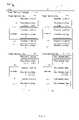
- FIG. 1is a schematic diagram showing an example of an organizational structure for a multiple-die flash memory package on a printed circuit board.
- FIG. 2is a schematic diagram of a flash memory system illustrating a variety of disabling mechanisms for disabling individual die in a flash memory device.
- FIG. 3is a block diagram showing a system for testing flash memory, disabling defective flash die, and providing a label.
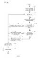
- FIG. 4is a flow diagram illustrating a method for disabling defective dies after a flash memory test is performed.
- FIG. 1shows an example of an organizational structure 100 for a multiple-die flash memory package.
- the organizational structure 100may be used in various applications, such as portable music devices, personal digital assistants, cell phones, handheld or laptop computers, and embedded systems, for example.
- the structure 100includes a printed circuit board (PCB) 105 on which a flash memory package 110 may be mounted.
- PCBprinted circuit board
- a flash memory packagemay include any practical number of flash memory dies, such as two, three, four, eight, or sixteen, for example.
- the flash memory package 110includes four flash memory dies 115 a , 115 b , 115 c , and 115 d .
- the flash memory package 110may be tested.
- the testsmay return test performance, such as a test score, for at least one flash memory die. Based on the test performance, some of the flash memory dies in the package may be identified to be defective according to a set of criterion, such as bit error rate, for example.
- any individual die that is identified as defectivemay be disabled.
- a disabled diemay be rendered inaccessible for storing and/or reading stored data.
- a variety of apparatus and methods for disabling an individual dieare discussed in further detail with reference to FIG. 2 .
- the manufacturermay be able to sell the flash memory for use with the non-disabled die in the package.
- the manufacturermay provide a label (or other indicia) on such a flash memory package to indicate that the flash memory package has a data storage capacity based on the non-disabled flash memory die(s).
- each of the flash memory dies 115 a , 115 b , 115 c , 115 d in the package 110includes three flash memory blocks 120 and a controller 125 . Some implementations may have more or fewer memory blocks.
- Each of the flash memory blocks 120includes multiple (e.g., 64 or 128) flash memory pages 130 .
- Each flash memory page 130includes multiple flash memory cells 135 .
- the flash memory cells 135store information by storing charges in the cell. A charge level in a flash memory cell represents the information stored in the cell.
- the flash memory cells 135may be single level cells in which each flash memory cell 135 stores one bit of information.
- the flash memory cells 135may be multiple levels cells in which each flash memory cell stores more than one bit of information.
- the flash memory cell 135may be defective when, for example, it cannot retain its charge level, or it cannot change its charge level, sufficiently to represent all possible bit values.
- the flash memory package 110 and the flash memory dies 115 a - 115 dhave a designed storage capacity based upon four fully functional dies.
- each of the flash memory blocks 120may be designed with a storage capacity of ten megabytes (MB).
- MBten megabytes
- each of the flash memory dies 115 a - 115 dhas a designed storage capacity of 30 MB.
- the flash memory package 110is designed to have a storage capacity of 120 MB.
- a manufacturermay test the flash memory package 110 for defective flash memory blocks after the flash memory dies 115 a - 115 d have been packaged into the flash memory package 110 . Based on a set of criteria, some of the flash memory dies 115 a - 115 d may be identified as defective.
- An exemplary test criterionmay be a function of a comparison between the number of defective flash memory blocks in a die and a threshold. If the number of defective flash memory blocks in an individual flash memory die exceeds the threshold, then the flash memory die may be identified as defective.
- a disabling operationmay be performed to disable the individual defective die rather than discarding the entire flash memory package. For example, if a test identifies that the flash memory die 115 a is defective, instead of discarding the package 110 , a disabling mechanism may disable the flash memory die 115 a , and the flash memory package may be operated and/or sold with a reduced storage capacity based on the flash memory dies 115 b - 115 d.
- a labeling mechanismmay be used to associate the disabled status information of the flash memory dies 115 a - 115 d with the flash memory package 110 .
- a labeling mechanismmay label (or otherwise indicate) that the flash memory package 110 may provide a storage capacity based on the storage capacities of dies 115 b , 115 c , and 115 d .
- the labeling mechanismmay label the flash memory package 110 with capacity of 90 MB, which is less than its nominal designed capacity of 120 MB.
- the package 110can be processed as a package 110 with 90 MB storage capacity.
- a sellermay sell the package as a 90 MB device.
- FIG. 2shows an example of a system 200 that illustrates a variety of disabling mechanisms that may be implemented to disable one or more individual flash memory dies in a flash memory package, such as the flash memory package 110 .
- These mechanismsmay be applied at the die level, package level, and/or board level, as appropriate.
- the disabling mechanisms described hereinare representative of possible implementations. These listed disabling mechanisms are intended to be illustrative, and are not intended to be limiting. Other mechanisms may be used, either alone or in combination with the illustrated examples, for disabling an individual die in a flash memory package. Manufacturers or users, for example, may choose one or more of the disabling mechanisms to disable one or more individual die in a flash memory package. In some applications, a combination of disabling mechanisms may be used.
- the system 200includes a flash memory package 205 and a memory controller 210 .
- the flash memory package 205may have a similar structure to the flash memory package 110 , or they may have different structures.
- the flash memory package 205includes four flash memory dies 215 a - 215 d , chip enable input pins 220 a - 220 d , a Vcc input pin 250 , and fuses 255 a - 255 b .
- the flash memory package 205also includes a JTAG port, which may be used for transferring test instructions or test results, for example, to and/or from a test device.
- test instructions or test resultsmay be transferred to and/or from the test device via a standard or custom data interface, which may provide for data transfers using synchronous or asynchronous transmissions of serial or parallel signals in analog and/or digital formats (e.g., out of band signals).
- Each of the flash memory dies 215 a - 215 dmay receive a chip enable signal via the chip enable pins 220 a - 220 d .
- Each flash memory dieincludes a corresponding flash memory block 225 a - 225 d , a Vcc input 230 a - 230 d , a controller 235 a - 235 d , and a chip enable (CE) input 240 a - 240 d .
- Each CE input 240 - 240 dmay be coupled to the chip enable pin 220 a - 220 d , for example, through a bond wire or other conductive path (e.g., in flip-chip packages).
- Each flash memory block 225 a - 225 dincludes a status register 245 a - 245 d that may store the status of each of the flash memory dies 215 a - 215 d in the flash memory package 205 .
- the status registers 245 a - 245 dmay each store a set of flags to indicate which of the flash memory dies 215 a - 215 d is to be disabled.
- the flash memory dies 215 a - 215 dmay draw operating power through a corresponding one of the fuses 255 a - 255 d and the Vcc inputs 230 a - 230 d .
- the Vcc inputs 230 a - 230 dare connected through fuses 255 a - 255 d , respectively, to a Vcc pin 250 on the flash memory package 205 .
- the controllers 235 a - 235 deach control read and write accesses to their respective flash memory blocks 225 a - 225 d .
- the controller 235 dmay control access to the flash memory die 215 d by not responding to a valid chip enable signal on the CE4 input 240 d .
- each of the CE inputs 240 a - 240 dmay connect to the corresponding CE pins 220 a - 220 d , respectively, through bond wires (not shown).
- the memory controller 210is external to the flash memory package 205 .
- the memory controller 210may be integrated into the package 205 with the flash memory dies 215 a - 215 d .
- the controller 210may be mounted on the same PCB with the flash memory package 205 , or located on another PCB or substrate and connected to the flash memory package 205 via a communication link, such as a cable, for example.
- the controller 210 of this exampleincludes a non-volatile memory (NVM) 260 and a logic 265 .
- the NVM 260may store enabling rules for the flash memory dies 215 a - 215 d and/or it may store the status of the flash memory dies 215 a - 215 d , such as the addresses of defective flash memory dies, for example.
- the logic 265which may include digital and/or analog hardware, and may perform operations upon the execution of instructions, may generate control signals according to the stored rules.
- the CE1-CE4 outputs on the controller 210are connected to the CE1-CE4 pins 220 a - 220 d on the package 205 through disabling circuits 270 a - 270 d.
- various mechanismscan be used to disable one or more selected flash memory dies at the die level, package level, and/or board level.
- disabling mechanisms located substantially within each of the dies 215 a - 215 dmay involve, for example, applying a command to a selected one of the controllers 235 a - 235 d , and/or storing copies of the disabled die status information for the flash memory dies 215 a - 215 d in the status registers 245 a - 245 d .
- a disabling mechanismmay apply a command to the controller 235 b to cause the controller 235 b to block (e.g., not process) requests to access memory locations in the die 215 b .
- copies of the disabled die status informationmay be maintained in other (non-disabled) die, or in a register that is separate from the disabled die.
- a disabling mechanismmay also set the status of the selected flash memory dies as “defective” in the status registers 245 a - 245 d .
- the controllers 235 a - 235 dmay be configured to prevent the defective flash memory dies from being enabled and/or accessed. Some operations at the die level may be performed on a die that is unpackaged (e.g., sawn wafer), in the process of being packaged, and/or fully enclosed in a package.
- a flash vendormay “mark” a block of cells, for example, as not to be used, for example, by storing a flag at the beginning of the block that, when read by a processor or controller, will inhibit reading and/or writing to the marked block.
- Flagsmay be placed, for example, at a designated location in the flash memory and/or in a register.
- a flagmay be placed to disable one or more blocks of memory, up to and including an entire die.
- Such a flagmay contain indicia about the disabled memory.
- the indiciamay indicate a size of the memory to disable, a status (e.g., defective, non-defective), and/or an effective usable storage capacity of the disabled memory.
- the effective usable storage capacity of the disabled memorymay be, for example, 100%, above about 99%, between about 96% and about 99%, at least about 95%, at least about 90%, or below 90%.
- Some implementationsmay permit one or more levels of access to the storage capacity of any disable die, and the access levels may be password protected.
- disabling mechanisms located substantially within the package 205may involve, for example, physically disabling connections from an individual die 215 a - 215 d to the corresponding CE pins 220 a - 220 d , and/or open circuiting power supply connections by cutting such connections (e.g., with a laser).
- Physically disabling the chip enable signal within the packagemay involve not populating or cutting a bond wire between a selected one of the CE pads (e.g., bond pads) 240 a - 240 d and the corresponding CE pins 220 a - 220 d .
- the disabling mechanismmay cut or not connect the bond wire from the CE2 pin 240 b to the CE2 pin 220 b to disable the flash memory die 215 b .
- a particular chip enable signal linemay be disabled by cutting a signal path for the chip enable signal.
- Open circuiting power supply connectionsmay involve disabling one of the flash memory dies 215 a - 215 d by blowing a selected one of the fuses 255 a - 255 d that connects the die to the power supply, or otherwise cutting the connection between the die and the power supply pin 250 .
- the cuttingmay involve techniques such as laser cutting, for example.
- packages of various typesmay be modified or manipulated to effectively disable an individual flash memory die.
- a ball grid array (BGA) packagefor example, an electrical path between a substrate bond wire pad for a CE input to a flash memory die may be cut or otherwise left unconnected from a corresponding solder ball.
- a CE input pin of a thin small outline package (TSOP)may be physically cut or otherwise prevented from making electrical connection to a circuit outside of the TSOP package.
- various methods for disabling defective diemay be implemented by circuit elements located substantially external to the flash memory package 205 .
- the controller 210may be configured to disable any of the flash memory dies 215 a - 215 d in the system 200 in response to a command from a host (not shown).
- the controller 210 and/or the disabling circuits 270 a - 270 dmay be implemented, for example, in a test fixture for operating with the flash memory package at one or more stages of the manufacturing process, for example, by using a socket to make electrical connections to the CE pins 220 a - 220 d .
- similar circuitsmay be coupled to the JTAG port.
- these or other circuit elements external to the flash memory package 205may, for example, operate to send signals to the flash memory package to disable selected ones of the dies 215 a - 215 d .
- Signals to disable one or more selected diesmay be communicated, in various implementations, using out-of-band (OOB) signaling to an appropriate receiving element in the flash memory package, via the CE pins 215 a - 215 d , the JTAG port, either alone or in combination with signals applied to one or more other pins (not shown), such as data, address, and/or control input pins.
- OOBout-of-band
- the controller 210may activate the disabling circuits 270 a - 270 d to disable external signals from driving the CE pins 220 a - 220 d , such as in, for example, a multi-chip module.
- each of the flash memory dies 215 a - 215 dmay be disabled by manipulating the appropriate chip enable signals to the corresponding chip enable pins 220 a - 220 d .
- the controller 210may be configured to prevent a disabled one of the dies 215 a - 215 d from receiving a chip enable signal at pins 220 a - 220 d .
- the CE1-CE4 outputs of the controller 210directly drive the CE inputs 220 a - 220 d
- the outputsmay be maintained at a signal level that does not enable a selected one (or more than one) of the dies 215 a - 215 d .
- the controller 210 and/or the disabling circuits 270 a - 270 dmay be operated to disable one or more selected chip enable signals.
- the board-level disabling circuits 270 a - 270 dmay use various hardware and/or software implementations to programmably disable selected chip enable signals.
- the disabling circuit 270 cmay disable the flash memory die 215 c if a circuit element (e.g., pull up-resistor, series resistor, jumper connection) is depopulated so as to prevent the CE3 pin 220 c of the package 205 from receiving a chip enable signal.
- a circuit elemente.g., pull up-resistor, series resistor, jumper connection
- the disabling circuit 270 cmay disable the flash memory die 215 c if a signal path is shorted to a rail (e.g., Vcc or ground) by a shorting path (e.g., populated with a substantially zero Ohm resistor or diode, active pull-up or pull-down transistor) to effectively short the chip enable signal transmission line so that the CE3 pin 220 c may not receive a valid chip enable signal.
- the disabling circuits 270 a - 270 dare analog switches and/or multiplexers that can connect or disconnect signals to the chip enable pins 220 a - 220 d under the control of the controller 210 , for example.
- the disabling circuits 270 a - 270 dmay be controllable buffers that can be individually controlled to disable a corresponding one of the flash memory dies 215 a - 215 d.
- the memory controller 210may execute commands to disable a flash memory die by controlling the output to each of the CE pins 220 a - 220 d . For example, if the memory controller 210 receives a command to disable the flash memory die 215 d , then the memory controller 210 may be configured not to send a chip enable signal to the CE4 pin on the controller 210 . Also, a disabling mechanism may activate one of the disabling circuits 270 a - 270 d in a variety of ways to disable communication of the chip enable signal between the memory controller 210 and the flash memory package 205 .
- a controllermay be receive a command to address a flash memory device as having a specified size, the size being an argument or a parameter associated with the command.
- a commandmay cause a controller to address only 3 Gigabytes of a flash memory that has a four dies of 1 Gigabyte storage capacity each.
- the command received by the controllermay effectively disable one die in the flash memory.
- FIG. 3shows an exemplary test environment 300 that is capable of testing a flash memory, identifying defective dies, disabling or providing for future disabling of the defective dies, and labeling the flash memory device to indicate the storage capacity of the flash dies that are not to be disabled.
- future disablingmay involve, for example, setting a disable flag in one of the status registers 245 a - 245 d .
- the corresponding controller 235 a - 235 d and/or the external controller 210may perform one or more operations, such as those described herein, to effectively disable the die that is associated with the disable flag.
- the test environment 300includes a test controller 305 and a test bed 310 .
- the test controller 305may perform operations to test a device under test (DUT) 315 on the test bed 310 .
- the DUT 315may be, for example, a set of flash memory dies, a wafer of flash memory dies, a flash memory mounted on a carrier substrate or in package, or a flash memory package mounted on a PCB.
- the test controller 305stores the overall test result in a storage device 320 .
- the test controller 305may retrieve failure information from a storage device 320 and operate a disabling mechanism 325 to disable any failed or defective flash memories in the test bed 310 .
- a labeling mechanism 330may then be activated to associate failure information with the DUT 315 .
- the test controller 305includes a supervising microprocessor 335 , a memory 340 , and a network interface 345 .
- the memory 340stores an application program 350 that the supervising microprocessor 335 may execute to perform a test.
- the application program 350includes a test code module 355 and a disable code module 360 .
- the supervising microprocessor 335may execute the test code module 355 by sending test instructions through the network interface 345 , which may include a JTAG or other (e.g., USB, parallel, RS-232, infrared, Ethernet) port, for example, to the test bed 310 .
- the test bed 310includes a test processor 365 and a test memory 370 .
- the supervising processor 335may execute the test code 355 to initialize a test, for example, by signaling the test processor 365 to initialize the DUT 315 and to load parameters (e.g., a test pattern) into the test memory 370 . The supervising processor 335 may then instruct the test processor 365 to run the test. When the test bed 310 finishes a test, the test bed 310 sends the test results to the test controller 305 . If there are more tests to be run, the test controller 305 may load and run another test on the DUT 315 . When all of the tests are done, the test controller 305 may calculate the overall score of the DUT 315 based on the test results and identify any flash memory dies in the DUT 315 that are defective.
- parameterse.g., a test pattern
- the number and types of errors that are detected during the testmay be compared to thresholds to determine whether the errors are acceptable (i.e., non-defective) for each die. Then, the test controller 305 may activate the disabling mechanism 325 to disable the defective die(s) in the DUT 315 .
- the disabling mechanism 325may disable defective individual die by providing conditions according to one or more of the disabling mechanisms described elsewhere in this document, such as those described with reference to FIG. 2 .
- a flash memory diemay be identified as defective if more than a threshold fraction of cells or blocks fail a manufacturer performance test. For example, if more than between about 2% and 4% of the blocks in a flash memory die fail performance testing, then the die may be identified as defective.
- a non-zero number of errorsare identified in a die during the test, but the errors fall within acceptable criteria (e.g., number of errors is less than a selected threshold), for example, then the identified errors may be addressed using other compensation (e.g., avoidance) and/or correction techniques. Accordingly, a die may have some errors but may nevertheless be identified as non-defective. Although such dies are not subject to being disabled, accesses to such dies may involve other error compensation methods.
- the disabling mechanism 325may disable the defective dies at the die, package, and/or board level using techniques such as those described with reference to FIG. 2 .
- the disabling mechanism 325may disable a defective die at the die level by storing its defective status in the status register 245 a - 245 d , at the package level by disconnecting its CE input 240 a - 240 d and/or open-circuiting its fuse 255 a - 255 d , and/or at the board level by providing a command to cause the disabling circuits 270 a - 270 d to disable its chip enable signal.
- the test controller 305may use the labeling mechanism 330 to provide a label to indicate the available flash memory capacity in the package.
- the labelmay indicate the available flash memory capacity based on the capacity of flash memory die that are not disabled or identified as failed.
- the label informationmay involve coded markings, bar codes, and/or text or graphical representations.
- the labelingmay be implemented, for example, by printed, etching, screening, stamping, laser printing, and/or applying an adhesive and/or pre-printed label that is visible from outside the package.
- labelingmay involve making one or more internal indications, either alone or in combination with the above-mentioned external markings. For example, information about the available capacity and/or memory map of the available flash memory may be etched, engraved, or otherwise marked internal to the package, such as on a die substrate. If the labeling mechanism is used at the die or wafer level, the labeling information may be applied in an unused or reserved area on the wafer, or on the defective die or group of dies.
- internal labelingmay involve storing digital information in a non-volatile memory in the package or in non-failed dies in the package. For example, labeling information may be stored in a status register and/or in a reserved portion of memory on a non-disabled die in the flash memory package.
- the label informationmay be read, retrieved, or otherwise recalled in a subsequent manufacturing process to sort or to package the flash memory package for use as a memory device with a storage capacity that is based on the labeling information.
- the test controller 305may be configured to perform an exemplary method 400 , which is illustrated in a flowchart in FIG. 4 .
- the method 400includes operations that the test controller 305 may perform when executing implementations of the disable code 360 .
- FIG. 3shows a single block of the disable code 360 stored in the memory 340 for execution by the test controller 305
- other processors or logicmay perform some or all of the operations, and may use instructions that are stored in locations other than in the memory 340 .
- the method 400begins at step 405 when the test controller 305 receives failure information about failed die in the DUT 315 .
- the test controller 305checks at step 410 whether the DUT 315 contains any failed die. If the test controller 305 identifies that the flash memory package contains no defective die to be disabled, then the test controller 305 associates, at step 415 , failure information (in this example, no die are defective) with the DUT 315 , for example, by storing the failure information in a database, an example of which is the storage device 320 .
- the labeling mechanism 330may apply, at step 417 , one or more external and/or internal indications of the available memory capacity in the package, and then the method 400 ends.
- test controller 305may identify the DUT type at step 420 .
- test typesinclude tests performed on unsawn wafers, dies, groups of dies, packaged dies, and/or packages connected to an external circuit (e.g., on a PCB), an example of which is described with reference to FIG. 2 .
- the test controller 305then, at step 425 , checks whether the disabling mechanism 325 can disable the defective die in the DUT 315 at the die level according to the identified DUT type. If the test controller 305 determines that the disabling mechanism 325 can disable the DUT 315 at the die level, then the test controller 305 may apply, at step 440 , a command to the disabling mechanism 325 , which may disable the failed dies at the die level.
- the test controller 305may send a command to the disabling mechanism 325 to apply a command to the controllers 235 a - 235 d in the flash memory dies 215 a - 215 d , to store status information pertaining to one or more of the flash memory dies 215 a - 215 d in the status registers 245 a - 245 d , or to disconnect the CE input 240 a - 240 d of the failed die from the corresponding CE pin 220 a - 220 d .
- the test controller 305performs step 415 .
- the test controller 305determines that the disabling mechanism 325 cannot disable the DUT 315 in the die level, then the test controller 305 checks, at step 435 , whether the disabling mechanism 325 can disable the DUT 315 at the package level according to the identified DUT type. If the test controller 305 determines that the disabling mechanism 325 can disable the DUT 315 at the package level, then the test controller 305 may apply, at step 440 , a command to the disabling mechanism 325 to disable the failed dies at the package level.
- the test controller 305may apply a command to the disabling mechanism 325 to physically disconnect the appropriate CE pins 220 a - 220 d , and/or to blow the fuse 255 a - 255 d (e.g., using a laser, excess current, etc. . . . ) that connects the power supply to the defective die. After disabling all the failed flash memory dies, the test controller 305 performs step 415 .
- the test controller 305determines that the disabling mechanism 325 cannot disable the DUT 315 at the package level, then, at step 445 the test controller 305 sends a command to use an external disabling mechanism to disable the failed dies.
- the test controller 305may send a command to the external controller 210 , to limit access to defective dies in the flash memory package by controlling the disabling circuits 270 a - 270 d .
- the test controller 305After sending commands to disable all the failed flash memory dies, the test controller 305 performs step 415 .
- the method 400may perform steps 425 and 435 in a different order, or together in combination with the step 420 .
- information about non-defective die informationmay be associated and/or labeled (as described herein) in addition or instead of information about defective die.
- NOR flash and/or NAND flash dieeither or both of which may be stacked together and/or adjacent to each other in a flash device, either alone, or with non-flash memory dies.
- flash memory devicewhich may contain one or more types of flash memory
- other implementationsmay be deployed in other data storage applications, which may include, thumb drive or memory stick, for example.
- the diemay be integrated into a package that uses vertically or horizontally (e.g., adjacent) stacked die arrangements.
- Such other data storage applicationsmay involve multi-chip modules (MCM), system on a chip (SoC), application specific integrated circuits (ASICs), and the like.
- MCMmulti-chip modules
- SoCsystem on a chip
- ASICsapplication specific integrated circuits
- Packagesmay be arranged for example, as plated through hole (PTH) (e.g., DIP), zero insertion force (e.g., certain socketed packages, SIMM), and/or surface mount (SMT) (e.g., PLCC, LCC, BGA, PGA, BGA, or LGA) packages.
- PTHplated through hole
- SIMMzero insertion force
- SMTsurface mount
- testing of flash memorymay also be performed in a product or electronic system after manufacturing is complete. Such self-diagnostic testing may be performed during operation, for example, in accordance with a maintenance schedule, in response to an operator request, and/or upon detecting a change in the bit error rate.
- the contents of a flash memory diemay from time to time be copied to another storage location to allow for a verification testing of the flash memory die. If an unacceptable error rate is detected for the die, the die may be disabled by a controller, an example of which is the controller 210 .
- the die identified as defectivemay be disabled by blowing a fuse, an example of which is any one of the fuses 255 a - 255 d .
- the controllers 235 of the non-defective diemay receive updated disable status information in the status registers 245 .
- individual disabled diemay be re-enabled during the product's useful life. For example, after 6 months of service, or after operating beyond a selected time, a previously disabled die (which may or may not have been identified as defective) may be re-enabled to provide information storage capacity for the product to thereby extend product life.
- the disabled memorymay be re-enabled in response to a time (e.g., with reference to a real time clock) and/or events (e.g., upon detection of degraded flash memory capacity as the number of operational cycles increases.)
- some of the above-described disabling mechanismsmay be used to disable one or more dies dynamically.
- Dynamic die disablingmay provide features such as, for example, price discrimination among different levels of storage capacity.
- an end usermay only wish to purchase a limited storage capacity, and the appropriate number of dies may be temporarily disabled according to implementations described above. This may be implemented in some implementations by configuring the controller 210 to temporarily disable some or all of the CE pins 220 a - 220 d .
- appropriate ones of the flash memory dies 215 a - 215 dmay be enabled by re-configuring the controller 210 to permit additional ones of the CE pins 220 a - 220 d to receive a chip enable signal.
- disabling mechanismsmay be arranged so as not to impede access or substantially increase access times to flash memory dies that are not disabled.
- an external host processor system(not shown) may initiate a memory access operation to read or write the flash memory block 225 a in the flash memory die 215 a by sending a read or write command to the controller 210 .
- the controller 210may check the status of the flash memory die 215 a and the enabling rules for the flash memory die 215 a in the NVM 260 . If it is appropriate to access the die 215 a according to the status and the enabling rules, then the logic 265 may initiate an enabling signal to the CE1 pin 220 a via the disabling circuit 270 a .
- the enabling signalmay then pass to the CE1 pin 240 a . If the Vcc pin 230 a is receiving electrical power, the controller 235 a may receive the enabling signal. Upon receiving the enabling signal, the controller 235 a may check the status register 245 a . If the information in the status register 245 a indicates that the flash memory die 215 a is not defective, then the controller 235 a may allow access to the flash memory die 215 a to complete the memory operation.
- Some implementations of the inventionmay be implemented in a computer system.
- various implementationsmay include digital and/or analog circuitry, computer hardware, firmware, software, or combinations thereof.
- Apparatuscan be implemented in a computer program product tangibly embodied in an information carrier, e.g., in a machine-readable storage device or in a propagated signal, for execution by a programmable processor; and methods can be performed by a programmable processor executing a program of instructions to perform functions of the invention by operating on input data and generating an output.
- the inventioncan be implemented advantageously in one or more computer programs that are executable on a programmable system including at least one programmable processor coupled to receive data and instructions from, and to transmit data and instructions to, a data storage system, at least one input device, and/or at least one output device.
- a computer programis a set of instructions that can be used, directly or indirectly, in a computer to perform a certain activity or bring about a certain result.
- a computer programcan be written in any form of programming language, including compiled or interpreted languages, and it can be deployed in any form, including as a stand-alone program or as a module, component, subroutine, or other unit suitable for use in a computing environment.
- Suitable processors for the execution of a program of instructionsinclude, by way of example, both general and special purpose microprocessors, which may include a single processor or one of multiple processors of any kind of computer.
- a processorwill receive instructions and data from a read-only memory or a random access memory or both.
- the essential elements of a computerare a processor for executing instructions and one or more memories for storing instructions and data.
- a computerwill also include, or be operatively coupled to communicate with, one or more mass storage devices for storing data files; such devices include magnetic disks, such as internal hard disks and removable disks; magneto-optical disks; and optical disks.
- Storage devices suitable for tangibly embodying computer program instructions and datainclude all forms of non-volatile memory, including, by way of example, semiconductor memory devices, such as EPROM, EEPROM, and flash memory devices; magnetic disks, such as internal hard disks and removable disks; magneto-optical disks; and, CD-ROM and DVD-ROM disks.
- semiconductor memory devicessuch as EPROM, EEPROM, and flash memory devices
- magnetic diskssuch as internal hard disks and removable disks
- magneto-optical disksand, CD-ROM and DVD-ROM disks.
- the processor and the memorycan be supplemented by, or incorporated in, ASICs (application-specific integrated circuits).
- ASICsapplication-specific integrated circuits
- one or more user-interface featuresmay be custom configured to perform specific functions.
- the inventionmay be implemented in a computer system that includes a graphical user interface and/or an Internet browser.
- some implementationsmay be implemented on a computer having a display device, such as a CRT (cathode ray tube) or LCD (liquid crystal display) monitor for displaying information to the user, a keyboard, and a pointing device, such as a mouse or a trackball by which the user can provide input to the computer.
- a display devicesuch as a CRT (cathode ray tube) or LCD (liquid crystal display) monitor for displaying information to the user
- a keyboardsuch as a keyboard
- a pointing devicesuch as a mouse or a trackball by which the user can provide input to the computer.
- flash memory controllersmay communicate using suitable communication methods, equipment, and techniques.
- the flash memory controllermay send or receive messages over a bus and/or using point-to-point communication in which a message is transported directly from the source to the receiver over a dedicated physical link (e.g., fiber optic link, point-to-point wiring, and daisy-chain).
- the components of the systemmay exchange information by any form or medium of analog or digital data communication, including packet-based messages on a communication network.
- Examples of communication networksinclude, e.g., a LAN (local area network), a WAN (wide area network), MAN (metropolitan area network), wireless and/or optical networks, and the computers and networks forming the Internet.
- implementationsmay transport messages by broadcasting to all or substantially all devices that are coupled together by a communication network, for example, by using omni-directional radio frequency (RF) signals.
- Still other implementationsmay transport messages characterized by high directivity, such as RF signals transmitted using directional (i.e., narrow beam) antennas or infrared signals that may optionally be used with focusing optics.
- RFradio frequency
- USB 2.0Firewire
- ATA/IDERS-232
- RS-422RS-485
- 802.11a/b/gWi-Fi
- EthernetIrDA
- FDDIfiber distributed data interface
- token-ring networksor multiplexing techniques based on frequency, time, or code division.
- Some implementationsmay optionally incorporate features such as error checking and correction (ECC) for data integrity, or security measures, such as encryption (e.g., WEP) and password protection.
- ECCerror checking and correction
- WEPSecure Digital
- each flash memory controller and/or status registermay be programmed with the same information and be initialized with substantially identical information stored in non-volatile memory.
- one or more flash memory devicesmay be custom configured to perform specific functions.
- one flash program devicemay be configured to perform dynamic testing of die in its own package or in another flash memory die in another package. Such testing may be performed at intervals (e.g., which may be user selected), or according to a regular maintenance schedule.
- the flash program devicemay generate signals to disable the identified die, whether in its own package or another package, using any single or combination of disabling mechanisms as described above. Such operations may be performed by a processor executing instructions to perform such operations.
Landscapes
- Techniques For Improving Reliability Of Storages (AREA)
- For Increasing The Reliability Of Semiconductor Memories (AREA)
- Semiconductor Memories (AREA)
- Non-Volatile Memory (AREA)
- Stroboscope Apparatuses (AREA)
- Read Only Memory (AREA)
- Debugging And Monitoring (AREA)
- Memory System (AREA)
- Testing Or Measuring Of Semiconductors Or The Like (AREA)
Abstract
Description
Claims (16)
Priority Applications (14)
| Application Number | Priority Date | Filing Date | Title |
|---|---|---|---|
| US11/334,087US7609561B2 (en) | 2006-01-18 | 2006-01-18 | Disabling faulty flash memory dies |
| TW099116206ATWI443669B (en) | 2006-01-18 | 2007-01-12 | Disabling a failed flash memory chip |
| TW096101323ATWI348700B (en) | 2006-01-18 | 2007-01-12 | Disabling faulty flash memory dies |
| DE602007008963TDE602007008963D1 (en) | 2006-01-18 | 2007-01-16 | Deactivation of faulty flash memory semiconductor chips |
| EP10166407AEP2224451B1 (en) | 2006-01-18 | 2007-01-16 | Disabling faulty flash memory dies |
| EP07000800AEP1811525B1 (en) | 2006-01-18 | 2007-01-16 | Disabling faulty flash memory dies |
| AT07000800TATE480856T1 (en) | 2006-01-18 | 2007-01-16 | DEACTIVATION OF FAULTY FLASH MEMORY SEMICONDUCTOR CHIPS |
| CN2007100022833ACN101004953B (en) | 2006-01-18 | 2007-01-17 | Disable faulty flash memory chips |
| CN2010102436040ACN101887759A (en) | 2006-01-18 | 2007-01-17 | Disabling faulty flash memory dies |
| JP2007009576AJP2007193811A (en) | 2006-01-18 | 2007-01-18 | Disabling faulty flash memory die |
| HK08100634.4AHK1106968B (en) | 2006-01-18 | 2008-01-17 | Disabling faulty flash memory dies |
| US12/559,341US8055959B2 (en) | 2006-01-18 | 2009-09-14 | Disabling faulty flash memory dies |
| JP2011020057AJP2011108267A (en) | 2006-01-18 | 2011-02-01 | Disabling faulty flash memory die |
| JP2012122367AJP5602187B2 (en) | 2006-01-18 | 2012-05-29 | Defect of defective flash memory die |
Applications Claiming Priority (1)
| Application Number | Priority Date | Filing Date | Title |
|---|---|---|---|
| US11/334,087US7609561B2 (en) | 2006-01-18 | 2006-01-18 | Disabling faulty flash memory dies |
Related Child Applications (1)
| Application Number | Title | Priority Date | Filing Date |
|---|---|---|---|
| US12/559,341DivisionUS8055959B2 (en) | 2006-01-18 | 2009-09-14 | Disabling faulty flash memory dies |
Publications (2)
| Publication Number | Publication Date |
|---|---|
| US20070165461A1 US20070165461A1 (en) | 2007-07-19 |
| US7609561B2true US7609561B2 (en) | 2009-10-27 |
Family
ID=38006905
Family Applications (2)
| Application Number | Title | Priority Date | Filing Date |
|---|---|---|---|
| US11/334,087Active2027-07-25US7609561B2 (en) | 2006-01-18 | 2006-01-18 | Disabling faulty flash memory dies |
| US12/559,341ActiveUS8055959B2 (en) | 2006-01-18 | 2009-09-14 | Disabling faulty flash memory dies |
Family Applications After (1)
| Application Number | Title | Priority Date | Filing Date |
|---|---|---|---|
| US12/559,341ActiveUS8055959B2 (en) | 2006-01-18 | 2009-09-14 | Disabling faulty flash memory dies |
Country Status (7)
| Country | Link |
|---|---|
| US (2) | US7609561B2 (en) |
| EP (2) | EP1811525B1 (en) |
| JP (3) | JP2007193811A (en) |
| CN (2) | CN101887759A (en) |
| AT (1) | ATE480856T1 (en) |
| DE (1) | DE602007008963D1 (en) |
| TW (2) | TWI348700B (en) |
Cited By (38)
| Publication number | Priority date | Publication date | Assignee | Title |
|---|---|---|---|---|
| US20090160482A1 (en)* | 2007-12-20 | 2009-06-25 | Xilinx, Inc. | Formation of a hybrid integrated circuit device |
| US20090259806A1 (en)* | 2008-04-15 | 2009-10-15 | Adtron, Inc. | Flash management using bad page tracking and high defect flash memory |
| US20100192041A1 (en)* | 2009-01-23 | 2010-07-29 | Micron Technology, Inc. | Memory devices and methods for managing error regions |
| US20110007539A1 (en)* | 2006-06-22 | 2011-01-13 | Micron Technology, Inc. | Test mode for multi-chip integrated circuit packages |
| US20110075482A1 (en)* | 2009-09-29 | 2011-03-31 | Zac Shepard | Maintaining integrity of preloaded content in non-volatile memory during surface mounting |
| US8446772B2 (en) | 2011-08-04 | 2013-05-21 | Sandisk Technologies Inc. | Memory die self-disable if programmable element is not trusted |
| US8976609B1 (en) | 2014-06-16 | 2015-03-10 | Sandisk Enterprise Ip Llc | Low-test memory stack for non-volatile storage |
| US9158681B1 (en) | 2014-09-02 | 2015-10-13 | Sandisk Technologies Inc. | Process and apparatus to reduce declared capacity of a storage device by conditionally trimming |
| US20150364218A1 (en)* | 2014-06-16 | 2015-12-17 | Sandisk Enterprise Ip Llc | Non-Volatile Memory Module with Physical-To-Physical Address Remapping |
| US9442670B2 (en) | 2013-09-03 | 2016-09-13 | Sandisk Technologies Llc | Method and system for rebalancing data stored in flash memory devices |
| US9519577B2 (en) | 2013-09-03 | 2016-12-13 | Sandisk Technologies Llc | Method and system for migrating data between flash memory devices |
| US9519427B2 (en) | 2014-09-02 | 2016-12-13 | Sandisk Technologies Llc | Triggering, at a host system, a process to reduce declared capacity of a storage device |
| US9524105B2 (en) | 2014-09-02 | 2016-12-20 | Sandisk Technologies Llc | Process and apparatus to reduce declared capacity of a storage device by altering an encoding format |
| US9524112B2 (en) | 2014-09-02 | 2016-12-20 | Sandisk Technologies Llc | Process and apparatus to reduce declared capacity of a storage device by trimming |
| US9552166B2 (en) | 2014-09-02 | 2017-01-24 | Sandisk Technologies Llc. | Process and apparatus to reduce declared capacity of a storage device by deleting data |
| US9563362B2 (en) | 2014-09-02 | 2017-02-07 | Sandisk Technologies Llc | Host system and process to reduce declared capacity of a storage device by trimming |
| US9563370B2 (en) | 2014-09-02 | 2017-02-07 | Sandisk Technologies Llc | Triggering a process to reduce declared capacity of a storage device |
| US9582202B2 (en) | 2014-09-02 | 2017-02-28 | Sandisk Technologies Llc | Process and apparatus to reduce declared capacity of a storage device by moving data |
| US9582220B2 (en) | 2014-09-02 | 2017-02-28 | Sandisk Technologies Llc | Notification of trigger condition to reduce declared capacity of a storage device in a multi-storage-device storage system |
| US9582193B2 (en) | 2014-09-02 | 2017-02-28 | Sandisk Technologies Llc | Triggering a process to reduce declared capacity of a storage device in a multi-storage-device storage system |
| US9582212B2 (en) | 2014-09-02 | 2017-02-28 | Sandisk Technologies Llc | Notification of trigger condition to reduce declared capacity of a storage device |
| US9582203B2 (en) | 2014-09-02 | 2017-02-28 | Sandisk Technologies Llc | Process and apparatus to reduce declared capacity of a storage device by reducing a range of logical addresses |
| US9606737B2 (en) | 2015-05-20 | 2017-03-28 | Sandisk Technologies Llc | Variable bit encoding per NAND flash cell to extend life of flash-based storage devices and preserve over-provisioning |
| US9613715B2 (en) | 2014-06-16 | 2017-04-04 | Sandisk Technologies Llc | Low-test memory stack for non-volatile storage |
| US9645749B2 (en) | 2014-05-30 | 2017-05-09 | Sandisk Technologies Llc | Method and system for recharacterizing the storage density of a memory device or a portion thereof |
| US9652153B2 (en) | 2014-09-02 | 2017-05-16 | Sandisk Technologies Llc | Process and apparatus to reduce declared capacity of a storage device by reducing a count of logical addresses |
| US9665311B2 (en) | 2014-09-02 | 2017-05-30 | Sandisk Technologies Llc | Process and apparatus to reduce declared capacity of a storage device by making specific logical addresses unavailable |
| US9891844B2 (en) | 2015-05-20 | 2018-02-13 | Sandisk Technologies Llc | Variable bit encoding per NAND flash cell to improve device endurance and extend life of flash-based storage devices |
| US9898364B2 (en) | 2014-05-30 | 2018-02-20 | Sandisk Technologies Llc | Method and system for dynamic word line based configuration of a three-dimensional memory device |
| US9946473B2 (en) | 2015-12-03 | 2018-04-17 | Sandisk Technologies Llc | Efficiently managing unmapped blocks to extend life of solid state drive |
| US9946483B2 (en) | 2015-12-03 | 2018-04-17 | Sandisk Technologies Llc | Efficiently managing unmapped blocks to extend life of solid state drive with low over-provisioning |
| US10002100B2 (en) | 2016-02-02 | 2018-06-19 | Xilinx, Inc. | Active-by-active programmable device |
| US10042806B2 (en) | 2016-02-02 | 2018-08-07 | Xilinx, Inc. | System-level interconnect ring for a programmable integrated circuit |
| US10452468B2 (en) | 2016-12-30 | 2019-10-22 | Western Digital Technologies, Inc. | Method and system for managing non-volatile memory |
| US11017822B1 (en)* | 2019-11-01 | 2021-05-25 | Xilinx, Inc. | Yield-centric power gated regulated supply design with programmable leakers |
| US11422888B2 (en) | 2020-10-14 | 2022-08-23 | Western Digital Technologies, Inc. | Data integrity check for writing data in memory |
| US20240071437A1 (en)* | 2022-08-30 | 2024-02-29 | Micron Technology, Inc. | Die Disablement |
| US12399648B2 (en) | 2022-09-06 | 2025-08-26 | Micron Technology, Inc. | Die-based rank management |
Families Citing this family (58)
| Publication number | Priority date | Publication date | Assignee | Title |
|---|---|---|---|---|
| US7837579B2 (en)* | 2007-03-20 | 2010-11-23 | Powermetal Technologies, Inc. | Baseball and softball bats with fused nano-structured metals and alloys |
| US7558130B2 (en)* | 2007-06-04 | 2009-07-07 | Micron Technology, Inc. | Adjustable drive strength apparatus, systems, and methods |
| JP5161560B2 (en)* | 2007-12-28 | 2013-03-13 | 株式会社東芝 | Semiconductor memory device |
| JP5372382B2 (en)* | 2008-01-09 | 2013-12-18 | ピーエスフォー ルクスコ エスエイアールエル | Semiconductor device |
| JP5106151B2 (en)* | 2008-01-28 | 2012-12-26 | 株式会社東芝 | Stacked stack NAND memory and semiconductor device |
| US20090196093A1 (en)* | 2008-01-31 | 2009-08-06 | Qimonda Ag | Stacked die memory |
| EP2099031A1 (en)* | 2008-03-07 | 2009-09-09 | Axalto S.A. | Methods for manufacturing a stack of memory circuits and for addressing a memory circuit, corresponding stack and device |
| US7964976B2 (en)* | 2008-08-20 | 2011-06-21 | Headway Technologies, Inc. | Layered chip package and method of manufacturing same |
| US8327066B2 (en)* | 2008-09-30 | 2012-12-04 | Samsung Electronics Co., Ltd. | Method of managing a solid state drive, associated systems and implementations |
| US7968374B2 (en)* | 2009-02-06 | 2011-06-28 | Headway Technologies, Inc. | Layered chip package with wiring on the side surfaces |
| CN201576679U (en)* | 2009-07-23 | 2010-09-08 | 茂邦电子有限公司 | Flash memory chip stack structure |
| TWM373598U (en)* | 2009-09-07 | 2010-02-01 | Power Mate Technology Co Ltd | Surface-mounted terminal |
| JP5311047B2 (en)* | 2009-09-11 | 2013-10-09 | 日本電気株式会社 | Test method for semiconductor memory device |
| US9779057B2 (en) | 2009-09-11 | 2017-10-03 | Micron Technology, Inc. | Autonomous memory architecture |
| US8466562B2 (en) | 2009-09-24 | 2013-06-18 | Headway Technologies, Inc. | Layered chip package |
| US7902677B1 (en) | 2009-10-28 | 2011-03-08 | Headway Technologies, Inc. | Composite layered chip package and method of manufacturing same |
| JP2011134410A (en)* | 2009-12-25 | 2011-07-07 | Toshiba Corp | Nonvolatile semiconductor memory device and test method of the same |
| KR101124331B1 (en)* | 2010-04-30 | 2012-03-19 | 주식회사 하이닉스반도체 | Semiconductor Apparatus |
| US8421243B2 (en) | 2010-06-24 | 2013-04-16 | Headway Technologies, Inc. | Layered chip package and method of manufacturing same |
| US8203216B2 (en) | 2010-07-13 | 2012-06-19 | Headway Technologies, Inc. | Layered chip package and method of manufacturing same |
| US8203215B2 (en) | 2010-07-13 | 2012-06-19 | Headway Technologies, Inc. | Layered chip package and method of manufacturing same |
| US8362602B2 (en)* | 2010-08-09 | 2013-01-29 | Headway Technologies, Inc. | Layered chip package and method of manufacturing same |
| US8397134B2 (en)* | 2010-08-30 | 2013-03-12 | Hamilton Sundstrand Corporation | System for handling of permanent bit errors in memory devices |
| US8541887B2 (en) | 2010-09-03 | 2013-09-24 | Headway Technologies, Inc. | Layered chip package and method of manufacturing same |
| US8595414B2 (en)* | 2010-09-30 | 2013-11-26 | Apple Inc. | Selectively combining commands for a system having non-volatile memory |
| US8441112B2 (en) | 2010-10-01 | 2013-05-14 | Headway Technologies, Inc. | Method of manufacturing layered chip package |
| US8618646B2 (en) | 2010-10-12 | 2013-12-31 | Headway Technologies, Inc. | Layered chip package and method of manufacturing same |
| US8652877B2 (en) | 2010-12-06 | 2014-02-18 | Headway Technologies, Inc. | Method of manufacturing layered chip package |
| KR101214285B1 (en)* | 2010-12-30 | 2012-12-20 | 에스케이하이닉스 주식회사 | Memory system and operating method thereof |
| US8253257B2 (en) | 2011-01-26 | 2012-08-28 | Headway Technologies, Inc. | Layered chip package and method of manufacturing the same |
| US8344494B2 (en) | 2011-04-11 | 2013-01-01 | Headway Technologies, Inc. | Layered chip package and method of manufacturing same |
| US9082474B2 (en)* | 2011-04-21 | 2015-07-14 | Micron Technology, Inc. | Method and apparatus for providing preloaded non-volatile memory content |
| US8358015B2 (en) | 2011-06-09 | 2013-01-22 | Headway Technologies, Inc. | Layered chip package and method of manufacturing same |
| US8653639B2 (en) | 2011-06-09 | 2014-02-18 | Headway Technologies, Inc. | Layered chip package and method of manufacturing same |
| WO2013003029A2 (en) | 2011-06-29 | 2013-01-03 | Rambus Inc. | Multi-element memory device with power control for individual elements |
| US8426979B2 (en) | 2011-07-18 | 2013-04-23 | Headway Technologies, Inc. | Composite layered chip package |
| US20130036255A1 (en)* | 2011-08-05 | 2013-02-07 | Apple Inc. | Testing memory subsystem connectivity |
| US8426981B2 (en)* | 2011-09-22 | 2013-04-23 | Headway Technologies, Inc. | Composite layered chip package |
| US20130100752A1 (en)* | 2011-10-20 | 2013-04-25 | Fluiditech Ip Limited | Method of restoring reconstructed memory spaces |
| CN102496388A (en)* | 2011-12-01 | 2012-06-13 | 深圳市华星光电技术有限公司 | Method for examining memory code of printed circuit board |
| US9875808B2 (en)* | 2013-01-15 | 2018-01-23 | Micron Technology, Inc. | Reclaimable semiconductor device package and associated systems and methods |
| CN104102599A (en)* | 2013-04-11 | 2014-10-15 | 华邦电子股份有限公司 | Flash memory device and data transmission method |
| US10013322B2 (en) | 2013-06-03 | 2018-07-03 | Hitachi, Ltd. | Storage apparatus and storage apparatus control method |
| US10003675B2 (en) | 2013-12-02 | 2018-06-19 | Micron Technology, Inc. | Packet processor receiving packets containing instructions, data, and starting location and generating packets containing instructions and data |
| US9389973B2 (en) | 2014-05-30 | 2016-07-12 | Oracle International Corporation | Memory error propagation for faster error recovery |
| JP2017045311A (en)* | 2015-08-27 | 2017-03-02 | 株式会社東芝 | Memory system |
| KR102529171B1 (en)* | 2016-02-26 | 2023-05-04 | 삼성전자주식회사 | Memory device diagnosis system |
| US10983865B2 (en)* | 2016-08-01 | 2021-04-20 | Hewlett Packard Enterprise Development Lp | Adjusting memory parameters |
| US10541044B2 (en)* | 2016-10-31 | 2020-01-21 | Qualcomm Incorporated | Providing efficient handling of memory array failures in processor-based systems |
| CN109961136B (en)* | 2017-12-14 | 2020-05-19 | 中科寒武纪科技股份有限公司 | Integrated circuit chip devices and related products |
| EP4060720A4 (en)* | 2019-11-15 | 2023-08-16 | Kioxia Corporation | STORAGE DEVICE AND STORAGE SYSTEM |
| US11397635B2 (en)* | 2019-12-09 | 2022-07-26 | Sandisk Technologies Llc | Block quality classification at testing for non-volatile memory, and multiple bad block flags for product diversity |
| US12393344B2 (en) | 2020-04-07 | 2025-08-19 | Micron Technology, Inc. | Apparatuses and methods for die replacement in stacked memory |
| KR102432739B1 (en)* | 2020-11-30 | 2022-08-16 | 주식회사 데이터세이브 | Data recovery method of USB memory device having multi-layered printed circuit board |
| US11675528B2 (en) | 2021-03-29 | 2023-06-13 | Western Digital Technologies, Inc. | Switch based BGA extension |
| US12164782B2 (en) | 2021-03-29 | 2024-12-10 | SanDisk Technologies, Inc. | Persistent switch-based storage controller |
| US12020771B2 (en)* | 2021-08-13 | 2024-06-25 | Micron Technology, Inc. | Die location detection for grouped memory dies |
| TWI769094B (en)* | 2021-10-07 | 2022-06-21 | 瑞昱半導體股份有限公司 | Multi-die package |
Citations (31)
| Publication number | Priority date | Publication date | Assignee | Title |
|---|---|---|---|---|
| US4992984A (en) | 1989-12-28 | 1991-02-12 | International Business Machines Corporation | Memory module utilizing partially defective memory chips |
| US5473753A (en) | 1992-10-30 | 1995-12-05 | Intel Corporation | Method of managing defects in flash disk memories |
| US5592641A (en) | 1993-06-30 | 1997-01-07 | Intel Corporation | Method and device for selectively locking write access to blocks in a memory array using write protect inputs and block enabled status |
| US5602987A (en) | 1989-04-13 | 1997-02-11 | Sandisk Corporation | Flash EEprom system |
| US5691945A (en)* | 1995-05-31 | 1997-11-25 | Macronix International Co., Ltd. | Technique for reconfiguring a high density memory |
| WO1998015149A1 (en) | 1996-10-03 | 1998-04-09 | Nokia Telecommunications Oy | A method of locating a mobile station |
| US5812861A (en)* | 1995-06-22 | 1998-09-22 | Intel Corporation | Override signal for forcing a powerdown of a flash memory |
| US5848009A (en) | 1996-10-08 | 1998-12-08 | Samsung Electronics Co., Ltd. | Integrated circuit memory devices that map nondefective memory cell blocks into continuous addresses |
| US5880996A (en) | 1995-07-28 | 1999-03-09 | Micron Technology, Inc. | Memory system having non-volatile data storage structure for memory control parameters and method |
| US5901105A (en)* | 1995-04-05 | 1999-05-04 | Ong; Adrian E | Dynamic random access memory having decoding circuitry for partial memory blocks |
| US5946257A (en) | 1996-07-24 | 1999-08-31 | Micron Technology, Inc. | Selective power distribution circuit for an integrated circuit |
| US6148435A (en) | 1997-12-24 | 2000-11-14 | Cypress Semiconductor Corporation | Optimized programming/erase parameters for programmable devices |
| US6269025B1 (en) | 2000-02-09 | 2001-07-31 | Advanced Micro Devices, Inc. | Memory system having a program and erase voltage modifier |
| US6304487B1 (en) | 2000-02-28 | 2001-10-16 | Advanced Micro Devices, Inc. | Register driven means to control programming voltages |
| US20010052637A1 (en)* | 1996-10-08 | 2001-12-20 | Salman Akram | Memory modules including capacity for additional memory |
| US6426893B1 (en) | 2000-02-17 | 2002-07-30 | Sandisk Corporation | Flash eeprom system with simultaneous multiple data sector programming and storage of physical block characteristics in other designated blocks |
| US20030007399A1 (en) | 2001-07-09 | 2003-01-09 | Hiromu Kinoshita | Semiconductor memory |
| US6721820B2 (en) | 2002-05-15 | 2004-04-13 | M-Systems Flash Disk Pioneers Ltd. | Method for improving performance of a flash-based storage system using specialized flash controllers |
| US6748562B1 (en) | 2000-10-31 | 2004-06-08 | Agilent Technologies, Inc. | Memory tester omits programming of addresses in detected bad columns |
| US6763424B2 (en) | 2001-01-19 | 2004-07-13 | Sandisk Corporation | Partial block data programming and reading operations in a non-volatile memory |
| US20040172576A1 (en) | 2001-09-28 | 2004-09-02 | Takeo Yoshii | Data writing apparatus, data writing method, and program |
| US20050023656A1 (en)* | 2002-08-08 | 2005-02-03 | Leedy Glenn J. | Vertical system integration |
| US6947332B2 (en) | 1991-04-11 | 2005-09-20 | Sandisk Corporation | Computer memory cards using flash EEPROM integrated circuit chips and memory-controller systems |
| US6956769B2 (en) | 2002-03-04 | 2005-10-18 | Samsung Electronics Co., Ltd. | Semiconductor memory device with a flexible redundancy scheme |
| US20060216841A1 (en)* | 2003-10-31 | 2006-09-28 | M-Systems Flash Disk Pioneers Ltd. | Method, system and computer-readable code for testing of flash memory |
| US7137011B1 (en) | 1993-09-01 | 2006-11-14 | Sandisk Corporation | Removable mother/daughter peripheral card |
| US7162569B2 (en) | 2002-02-22 | 2007-01-09 | Sandisk Corporation | Pipelined parallel programming operation in a non-volatile memory system |
| US7237046B2 (en) | 2003-03-27 | 2007-06-26 | Sandisk Il Ltd. | Data storage device with full access by all users |
| US7237074B2 (en) | 2003-06-13 | 2007-06-26 | Sandisk Corporation | Tracking cells for a memory system |
| US7240219B2 (en) | 2003-05-25 | 2007-07-03 | Sandisk Il Ltd. | Method and system for maintaining backup of portable storage devices |
| US7277337B1 (en)* | 2006-09-25 | 2007-10-02 | Kingston Technology Corp. | Memory module with a defective memory chip having defective blocks disabled by non-multiplexed address lines to the defective chip |
Family Cites Families (20)
| Publication number | Priority date | Publication date | Assignee | Title |
|---|---|---|---|---|
| US4891811A (en)* | 1987-02-13 | 1990-01-02 | International Business Machines Corporation | Efficient address test for large memories |
| JPH023843A (en)* | 1988-06-16 | 1990-01-09 | Mitsubishi Electric Corp | Ic memory card |
| US5822256A (en)* | 1994-09-06 | 1998-10-13 | Intel Corporation | Method and circuitry for usage of partially functional nonvolatile memory |
| JP3631277B2 (en)* | 1995-01-27 | 2005-03-23 | 株式会社日立製作所 | Memory module |
| US5619462A (en)* | 1995-07-31 | 1997-04-08 | Sgs-Thomson Microelectronics, Inc. | Fault detection for entire wafer stress test |
| US5754410A (en)* | 1996-09-11 | 1998-05-19 | International Business Machines Corporation | Multi-chip module with accessible test pads |
| JP3565687B2 (en)* | 1997-08-06 | 2004-09-15 | 沖電気工業株式会社 | Semiconductor memory device and control method thereof |
| US6360346B1 (en)* | 1997-08-27 | 2002-03-19 | Sony Corporation | Storage unit, method of checking storage unit, reading and writing method |
| JPH11242898A (en)* | 1998-02-25 | 1999-09-07 | Hitachi Ltd | Memory modules and electronic devices |
| US6301121B1 (en)* | 1999-04-05 | 2001-10-09 | Paul T. Lin | Direct-chip-attach (DCA) multiple chip module (MCM) with repair-chip ready site to simplify assembling and testing process |
| JP3805188B2 (en)* | 2000-10-16 | 2006-08-02 | シャープ株式会社 | Composite memory module and selection method thereof |
| JP5050303B2 (en)* | 2001-06-29 | 2012-10-17 | 富士通セミコンダクター株式会社 | Semiconductor test equipment |
| US7051242B2 (en)* | 2002-02-08 | 2006-05-23 | Hewlett-Packard Development Company, L.P. | Method and apparatus for improving yield by decommissioning optional units on a CPU due to manufacturing defects |
| US6901498B2 (en)* | 2002-12-09 | 2005-05-31 | Sandisk Corporation | Zone boundary adjustment for defects in non-volatile memories |
| US20050041453A1 (en)* | 2003-08-22 | 2005-02-24 | Brazis Paul W. | Method and apparatus for reading and writing to solid-state memory |
| US7305600B2 (en)* | 2003-08-29 | 2007-12-04 | International Business Machines Corporation | Partial good integrated circuit and method of testing same |
| US7200770B2 (en)* | 2003-12-31 | 2007-04-03 | Hewlett-Packard Development Company, L.P. | Restoring access to a failed data storage device in a redundant memory system |
| US7227797B2 (en)* | 2005-08-30 | 2007-06-05 | Hewlett-Packard Development Company, L.P. | Hierarchical memory correction system and method |
| JP2007088329A (en)* | 2005-09-26 | 2007-04-05 | Toshiba Corp | Multi-chip package type semiconductor device |
| US7477545B2 (en)* | 2007-06-14 | 2009-01-13 | Sandisk Corporation | Systems for programmable chip enable and chip address in semiconductor memory |
- 2006
- 2006-01-18USUS11/334,087patent/US7609561B2/enactiveActive
- 2007
- 2007-01-12TWTW096101323Apatent/TWI348700B/ennot_activeIP Right Cessation
- 2007-01-12TWTW099116206Apatent/TWI443669B/ennot_activeIP Right Cessation
- 2007-01-16ATAT07000800Tpatent/ATE480856T1/ennot_activeIP Right Cessation
- 2007-01-16EPEP07000800Apatent/EP1811525B1/ennot_activeNot-in-force
- 2007-01-16DEDE602007008963Tpatent/DE602007008963D1/enactiveActive
- 2007-01-16EPEP10166407Apatent/EP2224451B1/ennot_activeNot-in-force
- 2007-01-17CNCN2010102436040Apatent/CN101887759A/enactivePending
- 2007-01-17CNCN2007100022833Apatent/CN101004953B/ennot_activeExpired - Fee Related
- 2007-01-18JPJP2007009576Apatent/JP2007193811A/enactivePending
- 2009
- 2009-09-14USUS12/559,341patent/US8055959B2/enactiveActive
- 2011
- 2011-02-01JPJP2011020057Apatent/JP2011108267A/enactivePending
- 2012
- 2012-05-29JPJP2012122367Apatent/JP5602187B2/ennot_activeExpired - Fee Related
Patent Citations (41)
| Publication number | Priority date | Publication date | Assignee | Title |
|---|---|---|---|---|
| US6149316A (en) | 1989-04-13 | 2000-11-21 | Sandisk Corporation | Flash EEprom system |
| US5602987A (en) | 1989-04-13 | 1997-02-11 | Sandisk Corporation | Flash EEprom system |
| US5671229A (en) | 1989-04-13 | 1997-09-23 | Sandisk Corporation | Flash eeprom system with defect handling |
| US6914846B2 (en) | 1989-04-13 | 2005-07-05 | Sandisk Corporation | Flash EEprom system |
| US5719808A (en) | 1989-04-13 | 1998-02-17 | Sandisk Corporation | Flash EEPROM system |
| US6757842B2 (en) | 1989-04-13 | 2004-06-29 | Sandisk Corporation | Flash EEprom system |
| US4992984A (en) | 1989-12-28 | 1991-02-12 | International Business Machines Corporation | Memory module utilizing partially defective memory chips |
| US6947332B2 (en) | 1991-04-11 | 2005-09-20 | Sandisk Corporation | Computer memory cards using flash EEPROM integrated circuit chips and memory-controller systems |
| US5473753A (en) | 1992-10-30 | 1995-12-05 | Intel Corporation | Method of managing defects in flash disk memories |
| US5577194A (en) | 1992-10-30 | 1996-11-19 | Intel Corporation | Method of managing defects in flash disk memories |
| US6014755A (en) | 1992-10-30 | 2000-01-11 | Intel Corporation | Method of managing defects in flash disk memories |
| US5592641A (en) | 1993-06-30 | 1997-01-07 | Intel Corporation | Method and device for selectively locking write access to blocks in a memory array using write protect inputs and block enabled status |
| US7137011B1 (en) | 1993-09-01 | 2006-11-14 | Sandisk Corporation | Removable mother/daughter peripheral card |
| US5901105A (en)* | 1995-04-05 | 1999-05-04 | Ong; Adrian E | Dynamic random access memory having decoding circuitry for partial memory blocks |
| US5999480A (en)* | 1995-04-05 | 1999-12-07 | Micron Technology, Inc. | Dynamic random-access memory having a hierarchical data path |
| US5691945A (en)* | 1995-05-31 | 1997-11-25 | Macronix International Co., Ltd. | Technique for reconfiguring a high density memory |
| US5812861A (en)* | 1995-06-22 | 1998-09-22 | Intel Corporation | Override signal for forcing a powerdown of a flash memory |
| US5880996A (en) | 1995-07-28 | 1999-03-09 | Micron Technology, Inc. | Memory system having non-volatile data storage structure for memory control parameters and method |
| US5946257A (en) | 1996-07-24 | 1999-08-31 | Micron Technology, Inc. | Selective power distribution circuit for an integrated circuit |
| US6078540A (en)* | 1996-07-24 | 2000-06-20 | Micron Technology, Inc. | Selective power distribution circuit for an integrated circuit |
| US6356498B1 (en)* | 1996-07-24 | 2002-03-12 | Micron Technology, Inc. | Selective power distribution circuit for an integrated circuit |
| WO1998015149A1 (en) | 1996-10-03 | 1998-04-09 | Nokia Telecommunications Oy | A method of locating a mobile station |
| US5848009A (en) | 1996-10-08 | 1998-12-08 | Samsung Electronics Co., Ltd. | Integrated circuit memory devices that map nondefective memory cell blocks into continuous addresses |
| US20010052637A1 (en)* | 1996-10-08 | 2001-12-20 | Salman Akram | Memory modules including capacity for additional memory |
| US6148435A (en) | 1997-12-24 | 2000-11-14 | Cypress Semiconductor Corporation | Optimized programming/erase parameters for programmable devices |
| US6269025B1 (en) | 2000-02-09 | 2001-07-31 | Advanced Micro Devices, Inc. | Memory system having a program and erase voltage modifier |
| US6426893B1 (en) | 2000-02-17 | 2002-07-30 | Sandisk Corporation | Flash eeprom system with simultaneous multiple data sector programming and storage of physical block characteristics in other designated blocks |
| US6304487B1 (en) | 2000-02-28 | 2001-10-16 | Advanced Micro Devices, Inc. | Register driven means to control programming voltages |
| US6748562B1 (en) | 2000-10-31 | 2004-06-08 | Agilent Technologies, Inc. | Memory tester omits programming of addresses in detected bad columns |
| US6763424B2 (en) | 2001-01-19 | 2004-07-13 | Sandisk Corporation | Partial block data programming and reading operations in a non-volatile memory |
| US20030007399A1 (en) | 2001-07-09 | 2003-01-09 | Hiromu Kinoshita | Semiconductor memory |
| US20040172576A1 (en) | 2001-09-28 | 2004-09-02 | Takeo Yoshii | Data writing apparatus, data writing method, and program |
| US7162569B2 (en) | 2002-02-22 | 2007-01-09 | Sandisk Corporation | Pipelined parallel programming operation in a non-volatile memory system |
| US6956769B2 (en) | 2002-03-04 | 2005-10-18 | Samsung Electronics Co., Ltd. | Semiconductor memory device with a flexible redundancy scheme |
| US6721820B2 (en) | 2002-05-15 | 2004-04-13 | M-Systems Flash Disk Pioneers Ltd. | Method for improving performance of a flash-based storage system using specialized flash controllers |
| US20050023656A1 (en)* | 2002-08-08 | 2005-02-03 | Leedy Glenn J. | Vertical system integration |
| US7237046B2 (en) | 2003-03-27 | 2007-06-26 | Sandisk Il Ltd. | Data storage device with full access by all users |
| US7240219B2 (en) | 2003-05-25 | 2007-07-03 | Sandisk Il Ltd. | Method and system for maintaining backup of portable storage devices |
| US7237074B2 (en) | 2003-06-13 | 2007-06-26 | Sandisk Corporation | Tracking cells for a memory system |
| US20060216841A1 (en)* | 2003-10-31 | 2006-09-28 | M-Systems Flash Disk Pioneers Ltd. | Method, system and computer-readable code for testing of flash memory |
| US7277337B1 (en)* | 2006-09-25 | 2007-10-02 | Kingston Technology Corp. | Memory module with a defective memory chip having defective blocks disabled by non-multiplexed address lines to the defective chip |
Non-Patent Citations (11)
| Title |
|---|
| "17.3 RAIDO-Striping," by T. Rhodes and M. Stokely; FreeBSD Handbook, Chpt 17 GEOM: Modular Disk Transformation Framework; pp. 1-3. |
| "512M x 8 Bit / 1G x 8 Bit NAND Flash Memory," Flash Memory, Samsung Electronics, pp. 1-38. |
| "Advanced Technology Attachment," http://foldoc.doc.ic.ac.uk/foldoc. |
| "ATA Flash Disk Controller," 2004 Silicon Storage Technology, Inc.; pp. 1-76. |
| "Common Flash Memory Interface Specification," Release 2.0, Dec. 1, 2001; pp. 1-25. |
| "Portalplayer, Inc.-Products," http://www.portalplayer.com/products/index.html, pp. 1-5. |
| "RAID," SearchWinSystems.Com Learning Guide: Backup Solutions, pp. 1-3. |
| "Two Technologies Compared: NOR vs. NAND White Paper," Jul. 2003, 91-SR-012-04-8L, Rev 1.1, pp. 1-14. |
| Chinese Examiner Wu Yun, The Patent Office of the People's Republic of China Non-Final Office Action in Chinese Appl. No. 200710002283.3, mailed Apr. 17, 2009, 6 pages. |
| K9XXG08UXM-Preliminary Flash Memory-Samsung Electronics, pp. 1-44. |
| The extended European Search Report, 07000800.8-2210 date mailed Aug. 10, 2007, 8 pages. |
Cited By (58)
| Publication number | Priority date | Publication date | Assignee | Title |
|---|---|---|---|---|
| US20110007539A1 (en)* | 2006-06-22 | 2011-01-13 | Micron Technology, Inc. | Test mode for multi-chip integrated circuit packages |
| US8136000B2 (en)* | 2006-06-22 | 2012-03-13 | Micron Technology, Inc. | Test mode for multi-chip integrated circuit packages |
| US20090160482A1 (en)* | 2007-12-20 | 2009-06-25 | Xilinx, Inc. | Formation of a hybrid integrated circuit device |
| US8293547B2 (en) | 2007-12-20 | 2012-10-23 | Xilinx, Inc. | Hybrid integrated circuit device |
| US7919845B2 (en) | 2007-12-20 | 2011-04-05 | Xilinx, Inc. | Formation of a hybrid integrated circuit device |
| US20110147949A1 (en)* | 2007-12-20 | 2011-06-23 | Xilinx, Inc. | Hybrid integrated circuit device |
| US20090259806A1 (en)* | 2008-04-15 | 2009-10-15 | Adtron, Inc. | Flash management using bad page tracking and high defect flash memory |
| US11145384B2 (en) | 2009-01-23 | 2021-10-12 | Micron Technology, Inc. | Memory devices and methods for managing error regions |
| US8127185B2 (en)* | 2009-01-23 | 2012-02-28 | Micron Technology, Inc. | Memory devices and methods for managing error regions |
| US8392771B2 (en) | 2009-01-23 | 2013-03-05 | Micron Technology, Inc. | Memory devices and methods for managing error regions |
| US20100192041A1 (en)* | 2009-01-23 | 2010-07-29 | Micron Technology, Inc. | Memory devices and methods for managing error regions |
| US9953724B2 (en) | 2009-01-23 | 2018-04-24 | Micron Technology, Inc. | Memory devices and methods for managing error regions |
| US8990647B2 (en) | 2009-01-23 | 2015-03-24 | Micron Technology, Inc. | Memory devices and methods for managing error regions |
| US11915774B2 (en) | 2009-01-23 | 2024-02-27 | Micron Technology, Inc. | Memory devices and methods for managing error regions |
| US10347356B2 (en)* | 2009-01-23 | 2019-07-09 | Micron Technology, Inc. | Memory devices and methods for managing error regions |
| US8179717B2 (en)* | 2009-09-29 | 2012-05-15 | Sandisk Technologies Inc. | Maintaining integrity of preloaded content in non-volatile memory during surface mounting |
| US20110075482A1 (en)* | 2009-09-29 | 2011-03-31 | Zac Shepard | Maintaining integrity of preloaded content in non-volatile memory during surface mounting |
| US8446772B2 (en) | 2011-08-04 | 2013-05-21 | Sandisk Technologies Inc. | Memory die self-disable if programmable element is not trusted |
| US9519577B2 (en) | 2013-09-03 | 2016-12-13 | Sandisk Technologies Llc | Method and system for migrating data between flash memory devices |
| US9442670B2 (en) | 2013-09-03 | 2016-09-13 | Sandisk Technologies Llc | Method and system for rebalancing data stored in flash memory devices |
| US9898364B2 (en) | 2014-05-30 | 2018-02-20 | Sandisk Technologies Llc | Method and system for dynamic word line based configuration of a three-dimensional memory device |
| US9645749B2 (en) | 2014-05-30 | 2017-05-09 | Sandisk Technologies Llc | Method and system for recharacterizing the storage density of a memory device or a portion thereof |
| US20150364218A1 (en)* | 2014-06-16 | 2015-12-17 | Sandisk Enterprise Ip Llc | Non-Volatile Memory Module with Physical-To-Physical Address Remapping |
| US8976609B1 (en) | 2014-06-16 | 2015-03-10 | Sandisk Enterprise Ip Llc | Low-test memory stack for non-volatile storage |
| US9653184B2 (en)* | 2014-06-16 | 2017-05-16 | Sandisk Technologies Llc | Non-volatile memory module with physical-to-physical address remapping |
| US9613715B2 (en) | 2014-06-16 | 2017-04-04 | Sandisk Technologies Llc | Low-test memory stack for non-volatile storage |
| US9582212B2 (en) | 2014-09-02 | 2017-02-28 | Sandisk Technologies Llc | Notification of trigger condition to reduce declared capacity of a storage device |
| US9524112B2 (en) | 2014-09-02 | 2016-12-20 | Sandisk Technologies Llc | Process and apparatus to reduce declared capacity of a storage device by trimming |
| US9582220B2 (en) | 2014-09-02 | 2017-02-28 | Sandisk Technologies Llc | Notification of trigger condition to reduce declared capacity of a storage device in a multi-storage-device storage system |
| US9582203B2 (en) | 2014-09-02 | 2017-02-28 | Sandisk Technologies Llc | Process and apparatus to reduce declared capacity of a storage device by reducing a range of logical addresses |
| US9158681B1 (en) | 2014-09-02 | 2015-10-13 | Sandisk Technologies Inc. | Process and apparatus to reduce declared capacity of a storage device by conditionally trimming |
| US9582202B2 (en) | 2014-09-02 | 2017-02-28 | Sandisk Technologies Llc | Process and apparatus to reduce declared capacity of a storage device by moving data |
| US9563370B2 (en) | 2014-09-02 | 2017-02-07 | Sandisk Technologies Llc | Triggering a process to reduce declared capacity of a storage device |
| US9563362B2 (en) | 2014-09-02 | 2017-02-07 | Sandisk Technologies Llc | Host system and process to reduce declared capacity of a storage device by trimming |
| US9652153B2 (en) | 2014-09-02 | 2017-05-16 | Sandisk Technologies Llc | Process and apparatus to reduce declared capacity of a storage device by reducing a count of logical addresses |
| US9665311B2 (en) | 2014-09-02 | 2017-05-30 | Sandisk Technologies Llc | Process and apparatus to reduce declared capacity of a storage device by making specific logical addresses unavailable |
| US9519427B2 (en) | 2014-09-02 | 2016-12-13 | Sandisk Technologies Llc | Triggering, at a host system, a process to reduce declared capacity of a storage device |
| US9524105B2 (en) | 2014-09-02 | 2016-12-20 | Sandisk Technologies Llc | Process and apparatus to reduce declared capacity of a storage device by altering an encoding format |
| US9552166B2 (en) | 2014-09-02 | 2017-01-24 | Sandisk Technologies Llc. | Process and apparatus to reduce declared capacity of a storage device by deleting data |
| US9582193B2 (en) | 2014-09-02 | 2017-02-28 | Sandisk Technologies Llc | Triggering a process to reduce declared capacity of a storage device in a multi-storage-device storage system |
| US9864525B2 (en) | 2015-05-20 | 2018-01-09 | Sandisk Technologies Llc | Variable bit encoding per NAND flash cell to extend life of flash-based storage devices and preserve over-provisioning |
| US9606737B2 (en) | 2015-05-20 | 2017-03-28 | Sandisk Technologies Llc | Variable bit encoding per NAND flash cell to extend life of flash-based storage devices and preserve over-provisioning |
| US9891844B2 (en) | 2015-05-20 | 2018-02-13 | Sandisk Technologies Llc | Variable bit encoding per NAND flash cell to improve device endurance and extend life of flash-based storage devices |
| US9946473B2 (en) | 2015-12-03 | 2018-04-17 | Sandisk Technologies Llc | Efficiently managing unmapped blocks to extend life of solid state drive |
| US9946483B2 (en) | 2015-12-03 | 2018-04-17 | Sandisk Technologies Llc | Efficiently managing unmapped blocks to extend life of solid state drive with low over-provisioning |
| USRE49163E1 (en) | 2016-02-02 | 2022-08-09 | Xilinx, Inc. | Active-by-active programmable device |
| US10042806B2 (en) | 2016-02-02 | 2018-08-07 | Xilinx, Inc. | System-level interconnect ring for a programmable integrated circuit |
| US10002100B2 (en) | 2016-02-02 | 2018-06-19 | Xilinx, Inc. | Active-by-active programmable device |
| USRE50370E1 (en) | 2016-02-02 | 2025-04-08 | Xilinx, Inc. | Active-by-active programmable device |
| US11010239B2 (en) | 2016-12-30 | 2021-05-18 | Western Digital Technologies, Inc. | Method and system for managing memory device |
| US10452468B2 (en) | 2016-12-30 | 2019-10-22 | Western Digital Technologies, Inc. | Method and system for managing non-volatile memory |
| US11301318B2 (en) | 2016-12-30 | 2022-04-12 | Western Digital Technologies, Inc. | Method and system for managing memory device |
| US11714703B2 (en) | 2016-12-30 | 2023-08-01 | Western Digital Technologies, Inc. | Method and system for managing memory device |
| US11017822B1 (en)* | 2019-11-01 | 2021-05-25 | Xilinx, Inc. | Yield-centric power gated regulated supply design with programmable leakers |
| US11422888B2 (en) | 2020-10-14 | 2022-08-23 | Western Digital Technologies, Inc. | Data integrity check for writing data in memory |
| US20240071437A1 (en)* | 2022-08-30 | 2024-02-29 | Micron Technology, Inc. | Die Disablement |
| US12300351B2 (en)* | 2022-08-30 | 2025-05-13 | Micron Technology, Inc. | Die disablement |
| US12399648B2 (en) | 2022-09-06 | 2025-08-26 | Micron Technology, Inc. | Die-based rank management |
Also Published As
| Publication number | Publication date |
|---|---|
| TW201037715A (en) | 2010-10-16 |
| EP2224451B1 (en) | 2013-03-06 |
| JP2012185850A (en) | 2012-09-27 |
| TWI443669B (en) | 2014-07-01 |
| CN101004953A (en) | 2007-07-25 |
| JP2007193811A (en) | 2007-08-02 |
| HK1106968A1 (en) | 2008-03-20 |
| JP2011108267A (en) | 2011-06-02 |
| JP5602187B2 (en) | 2014-10-08 |
| US20100002512A1 (en) | 2010-01-07 |
| EP1811525A2 (en) | 2007-07-25 |
| TW200735115A (en) | 2007-09-16 |
| US8055959B2 (en) | 2011-11-08 |
| DE602007008963D1 (en) | 2010-10-21 |
| CN101004953B (en) | 2010-09-08 |
| ATE480856T1 (en) | 2010-09-15 |
| CN101887759A (en) | 2010-11-17 |
| US20070165461A1 (en) | 2007-07-19 |
| EP2224451A1 (en) | 2010-09-01 |
| EP1811525A3 (en) | 2007-09-12 |
| TWI348700B (en) | 2011-09-11 |
| EP1811525B1 (en) | 2010-09-08 |
Similar Documents
| Publication | Publication Date | Title |
|---|---|---|
| US7609561B2 (en) | Disabling faulty flash memory dies | |
| JP5321924B2 (en) | Reconfigurable connection for stacked semiconductor devices | |
| US7433229B2 (en) | Flash memory device with shunt | |
| US8767491B1 (en) | Apparatus and method for remapping addresses of defective memory locations to redundant memory locations | |
| US8208325B2 (en) | Semiconductor device, semiconductor package and memory repair method | |
| US8446772B2 (en) | Memory die self-disable if programmable element is not trusted | |
| US20040261049A1 (en) | Circuit and method for error test, recordation, and repair | |
| US20170228328A1 (en) | Method and apparatus for providing small form-factor pluggable (“sfp”) non-volatile memory (“nvm”) storage devices | |
| US20110007539A1 (en) | Test mode for multi-chip integrated circuit packages | |
| US9159451B2 (en) | Testing system and testing method thereof | |
| JP2010097686A (en) | Inspection method of solid-state drive having removable auxiliary inspection terminal | |
| CN106463158A (en) | Memory device having controller with local memory | |
| US7292487B1 (en) | Independent polling for multi-page programming | |
| CN1183549C (en) | Test device for testing memory | |
| US7936057B2 (en) | High bandwidth package | |
| US9019786B2 (en) | Repair system for repairing defect using E fuses and method of controlling the same | |
| KR20130104732A (en) | Test circuit, memory system and test method of memory system | |
| KR20100041514A (en) | Solid state drive apparatus reducing a test time and method for testing the same | |
| KR20110010381A (en) | Semiconductor memory device including self repair function and its self repair method | |
| HK1106968B (en) | Disabling faulty flash memory dies | |
| CN117457056A (en) | Memory system, operation method thereof and controller of memory device | |
| WO2001073949A1 (en) | Electrical id circuit and method | |
| US12061795B2 (en) | Repair element availability communication | |
| JP2010097629A (en) | Nonvolatile semiconductor memory device |
Legal Events
| Date | Code | Title | Description |
|---|---|---|---|
| AS | Assignment | Owner name:APPLE COMPUTER, INC., CALIFORNIA Free format text:ASSIGNMENT OF ASSIGNORS INTEREST;ASSIGNORS:CORNWELL, MICHAEL J.;DUDTE, CHRISTOPHER P.;REEL/FRAME:017429/0347 Effective date:20060117 | |
| AS | Assignment | Owner name:APPLE INC.,CALIFORNIA Free format text:CHANGE OF NAME;ASSIGNOR:APPLE COMPUTER, INC.;REEL/FRAME:019142/0226 Effective date:20070109 Owner name:APPLE INC., CALIFORNIA Free format text:CHANGE OF NAME;ASSIGNOR:APPLE COMPUTER, INC.;REEL/FRAME:019142/0226 Effective date:20070109 | |
| FEPP | Fee payment procedure | Free format text:PAYOR NUMBER ASSIGNED (ORIGINAL EVENT CODE: ASPN); ENTITY STATUS OF PATENT OWNER: LARGE ENTITY | |
| STCF | Information on status: patent grant | Free format text:PATENTED CASE | |
| FEPP | Fee payment procedure | Free format text:PAYER NUMBER DE-ASSIGNED (ORIGINAL EVENT CODE: RMPN); ENTITY STATUS OF PATENT OWNER: LARGE ENTITY Free format text:PAYOR NUMBER ASSIGNED (ORIGINAL EVENT CODE: ASPN); ENTITY STATUS OF PATENT OWNER: LARGE ENTITY | |
| CC | Certificate of correction | ||
| FPAY | Fee payment | Year of fee payment:4 | |
| FPAY | Fee payment | Year of fee payment:8 | |
| MAFP | Maintenance fee payment | Free format text:PAYMENT OF MAINTENANCE FEE, 12TH YEAR, LARGE ENTITY (ORIGINAL EVENT CODE: M1553); ENTITY STATUS OF PATENT OWNER: LARGE ENTITY Year of fee payment:12 |