US7608104B2 - Prostheses, tools and methods for replacement of natural facet joints with artifical facet joint surfaces - Google Patents
Prostheses, tools and methods for replacement of natural facet joints with artifical facet joint surfacesDownload PDFInfo
- Publication number
- US7608104B2 US7608104B2US10/973,834US97383404AUS7608104B2US 7608104 B2US7608104 B2US 7608104B2US 97383404 AUS97383404 AUS 97383404AUS 7608104 B2US7608104 B2US 7608104B2
- Authority
- US
- United States
- Prior art keywords
- cephalad
- prosthesis
- caudal
- facet joint
- bearing
- Prior art date
- Legal status (The legal status is an assumption and is not a legal conclusion. Google has not performed a legal analysis and makes no representation as to the accuracy of the status listed.)
- Active, expires
Links
Images


Classifications
- A—HUMAN NECESSITIES
- A61—MEDICAL OR VETERINARY SCIENCE; HYGIENE
- A61F—FILTERS IMPLANTABLE INTO BLOOD VESSELS; PROSTHESES; DEVICES PROVIDING PATENCY TO, OR PREVENTING COLLAPSING OF, TUBULAR STRUCTURES OF THE BODY, e.g. STENTS; ORTHOPAEDIC, NURSING OR CONTRACEPTIVE DEVICES; FOMENTATION; TREATMENT OR PROTECTION OF EYES OR EARS; BANDAGES, DRESSINGS OR ABSORBENT PADS; FIRST-AID KITS
- A61F2/00—Filters implantable into blood vessels; Prostheses, i.e. artificial substitutes or replacements for parts of the body; Appliances for connecting them with the body; Devices providing patency to, or preventing collapsing of, tubular structures of the body, e.g. stents
- A61F2/02—Prostheses implantable into the body
- A61F2/30—Joints
- A61F2/44—Joints for the spine, e.g. vertebrae, spinal discs
- A61F2/4405—Joints for the spine, e.g. vertebrae, spinal discs for apophyseal or facet joints, i.e. between adjacent spinous or transverse processes
- A—HUMAN NECESSITIES
- A61—MEDICAL OR VETERINARY SCIENCE; HYGIENE
- A61B—DIAGNOSIS; SURGERY; IDENTIFICATION
- A61B17/00—Surgical instruments, devices or methods
- A61B17/16—Instruments for performing osteoclasis; Drills or chisels for bones; Trepans
- A61B17/17—Guides or aligning means for drills, mills, pins or wires
- A61B17/1739—Guides or aligning means for drills, mills, pins or wires specially adapted for particular parts of the body
- A61B17/1757—Guides or aligning means for drills, mills, pins or wires specially adapted for particular parts of the body for the spine
- A—HUMAN NECESSITIES
- A61—MEDICAL OR VETERINARY SCIENCE; HYGIENE
- A61F—FILTERS IMPLANTABLE INTO BLOOD VESSELS; PROSTHESES; DEVICES PROVIDING PATENCY TO, OR PREVENTING COLLAPSING OF, TUBULAR STRUCTURES OF THE BODY, e.g. STENTS; ORTHOPAEDIC, NURSING OR CONTRACEPTIVE DEVICES; FOMENTATION; TREATMENT OR PROTECTION OF EYES OR EARS; BANDAGES, DRESSINGS OR ABSORBENT PADS; FIRST-AID KITS
- A61F2/00—Filters implantable into blood vessels; Prostheses, i.e. artificial substitutes or replacements for parts of the body; Appliances for connecting them with the body; Devices providing patency to, or preventing collapsing of, tubular structures of the body, e.g. stents
- A61F2/02—Prostheses implantable into the body
- A61F2/30—Joints
- A61F2/46—Special tools for implanting artificial joints
- A61F2/4603—Special tools for implanting artificial joints for insertion or extraction of endoprosthetic joints or of accessories thereof
- A61F2/4611—Special tools for implanting artificial joints for insertion or extraction of endoprosthetic joints or of accessories thereof of spinal prostheses
- A—HUMAN NECESSITIES
- A61—MEDICAL OR VETERINARY SCIENCE; HYGIENE
- A61B—DIAGNOSIS; SURGERY; IDENTIFICATION
- A61B17/00—Surgical instruments, devices or methods
- A61B17/56—Surgical instruments or methods for treatment of bones or joints; Devices specially adapted therefor
- A61B17/58—Surgical instruments or methods for treatment of bones or joints; Devices specially adapted therefor for osteosynthesis, e.g. bone plates, screws or setting implements
- A61B17/68—Internal fixation devices, including fasteners and spinal fixators, even if a part thereof projects from the skin
- A61B17/84—Fasteners therefor or fasteners being internal fixation devices
- A61B17/86—Pins or screws or threaded wires; nuts therefor
- A—HUMAN NECESSITIES
- A61—MEDICAL OR VETERINARY SCIENCE; HYGIENE
- A61F—FILTERS IMPLANTABLE INTO BLOOD VESSELS; PROSTHESES; DEVICES PROVIDING PATENCY TO, OR PREVENTING COLLAPSING OF, TUBULAR STRUCTURES OF THE BODY, e.g. STENTS; ORTHOPAEDIC, NURSING OR CONTRACEPTIVE DEVICES; FOMENTATION; TREATMENT OR PROTECTION OF EYES OR EARS; BANDAGES, DRESSINGS OR ABSORBENT PADS; FIRST-AID KITS
- A61F2/00—Filters implantable into blood vessels; Prostheses, i.e. artificial substitutes or replacements for parts of the body; Appliances for connecting them with the body; Devices providing patency to, or preventing collapsing of, tubular structures of the body, e.g. stents
- A61F2/02—Prostheses implantable into the body
- A61F2/30—Joints
- A61F2/44—Joints for the spine, e.g. vertebrae, spinal discs
- A61F2/442—Intervertebral or spinal discs, e.g. resilient
- A—HUMAN NECESSITIES
- A61—MEDICAL OR VETERINARY SCIENCE; HYGIENE
- A61F—FILTERS IMPLANTABLE INTO BLOOD VESSELS; PROSTHESES; DEVICES PROVIDING PATENCY TO, OR PREVENTING COLLAPSING OF, TUBULAR STRUCTURES OF THE BODY, e.g. STENTS; ORTHOPAEDIC, NURSING OR CONTRACEPTIVE DEVICES; FOMENTATION; TREATMENT OR PROTECTION OF EYES OR EARS; BANDAGES, DRESSINGS OR ABSORBENT PADS; FIRST-AID KITS
- A61F2/00—Filters implantable into blood vessels; Prostheses, i.e. artificial substitutes or replacements for parts of the body; Appliances for connecting them with the body; Devices providing patency to, or preventing collapsing of, tubular structures of the body, e.g. stents
- A61F2/02—Prostheses implantable into the body
- A61F2/30—Joints
- A61F2002/30001—Additional features of subject-matter classified in A61F2/28, A61F2/30 and subgroups thereof
- A61F2002/30108—Shapes
- A61F2002/3011—Cross-sections or two-dimensional shapes
- A61F2002/30138—Convex polygonal shapes
- A61F2002/30153—Convex polygonal shapes rectangular
- A—HUMAN NECESSITIES
- A61—MEDICAL OR VETERINARY SCIENCE; HYGIENE
- A61F—FILTERS IMPLANTABLE INTO BLOOD VESSELS; PROSTHESES; DEVICES PROVIDING PATENCY TO, OR PREVENTING COLLAPSING OF, TUBULAR STRUCTURES OF THE BODY, e.g. STENTS; ORTHOPAEDIC, NURSING OR CONTRACEPTIVE DEVICES; FOMENTATION; TREATMENT OR PROTECTION OF EYES OR EARS; BANDAGES, DRESSINGS OR ABSORBENT PADS; FIRST-AID KITS
- A61F2/00—Filters implantable into blood vessels; Prostheses, i.e. artificial substitutes or replacements for parts of the body; Appliances for connecting them with the body; Devices providing patency to, or preventing collapsing of, tubular structures of the body, e.g. stents
- A61F2/02—Prostheses implantable into the body
- A61F2/30—Joints
- A61F2002/30001—Additional features of subject-matter classified in A61F2/28, A61F2/30 and subgroups thereof
- A61F2002/30108—Shapes
- A61F2002/3011—Cross-sections or two-dimensional shapes
- A61F2002/30138—Convex polygonal shapes
- A61F2002/30156—Convex polygonal shapes triangular
- A—HUMAN NECESSITIES
- A61—MEDICAL OR VETERINARY SCIENCE; HYGIENE
- A61F—FILTERS IMPLANTABLE INTO BLOOD VESSELS; PROSTHESES; DEVICES PROVIDING PATENCY TO, OR PREVENTING COLLAPSING OF, TUBULAR STRUCTURES OF THE BODY, e.g. STENTS; ORTHOPAEDIC, NURSING OR CONTRACEPTIVE DEVICES; FOMENTATION; TREATMENT OR PROTECTION OF EYES OR EARS; BANDAGES, DRESSINGS OR ABSORBENT PADS; FIRST-AID KITS
- A61F2/00—Filters implantable into blood vessels; Prostheses, i.e. artificial substitutes or replacements for parts of the body; Appliances for connecting them with the body; Devices providing patency to, or preventing collapsing of, tubular structures of the body, e.g. stents
- A61F2/02—Prostheses implantable into the body
- A61F2/30—Joints
- A61F2002/30001—Additional features of subject-matter classified in A61F2/28, A61F2/30 and subgroups thereof
- A61F2002/30108—Shapes
- A61F2002/30199—Three-dimensional shapes
- A61F2002/30242—Three-dimensional shapes spherical
- A—HUMAN NECESSITIES
- A61—MEDICAL OR VETERINARY SCIENCE; HYGIENE
- A61F—FILTERS IMPLANTABLE INTO BLOOD VESSELS; PROSTHESES; DEVICES PROVIDING PATENCY TO, OR PREVENTING COLLAPSING OF, TUBULAR STRUCTURES OF THE BODY, e.g. STENTS; ORTHOPAEDIC, NURSING OR CONTRACEPTIVE DEVICES; FOMENTATION; TREATMENT OR PROTECTION OF EYES OR EARS; BANDAGES, DRESSINGS OR ABSORBENT PADS; FIRST-AID KITS
- A61F2/00—Filters implantable into blood vessels; Prostheses, i.e. artificial substitutes or replacements for parts of the body; Appliances for connecting them with the body; Devices providing patency to, or preventing collapsing of, tubular structures of the body, e.g. stents
- A61F2/02—Prostheses implantable into the body
- A61F2/30—Joints
- A61F2002/30001—Additional features of subject-matter classified in A61F2/28, A61F2/30 and subgroups thereof
- A61F2002/30316—The prosthesis having different structural features at different locations within the same prosthesis; Connections between prosthetic parts; Special structural features of bone or joint prostheses not otherwise provided for
- A61F2002/30329—Connections or couplings between prosthetic parts, e.g. between modular parts; Connecting elements
- A61F2002/30331—Connections or couplings between prosthetic parts, e.g. between modular parts; Connecting elements made by longitudinally pushing a protrusion into a complementarily-shaped recess, e.g. held by friction fit
- A61F2002/30332—Conically- or frustoconically-shaped protrusion and recess
- A—HUMAN NECESSITIES
- A61—MEDICAL OR VETERINARY SCIENCE; HYGIENE
- A61F—FILTERS IMPLANTABLE INTO BLOOD VESSELS; PROSTHESES; DEVICES PROVIDING PATENCY TO, OR PREVENTING COLLAPSING OF, TUBULAR STRUCTURES OF THE BODY, e.g. STENTS; ORTHOPAEDIC, NURSING OR CONTRACEPTIVE DEVICES; FOMENTATION; TREATMENT OR PROTECTION OF EYES OR EARS; BANDAGES, DRESSINGS OR ABSORBENT PADS; FIRST-AID KITS
- A61F2/00—Filters implantable into blood vessels; Prostheses, i.e. artificial substitutes or replacements for parts of the body; Appliances for connecting them with the body; Devices providing patency to, or preventing collapsing of, tubular structures of the body, e.g. stents
- A61F2/02—Prostheses implantable into the body
- A61F2/30—Joints
- A61F2002/30001—Additional features of subject-matter classified in A61F2/28, A61F2/30 and subgroups thereof
- A61F2002/30316—The prosthesis having different structural features at different locations within the same prosthesis; Connections between prosthetic parts; Special structural features of bone or joint prostheses not otherwise provided for
- A61F2002/30329—Connections or couplings between prosthetic parts, e.g. between modular parts; Connecting elements
- A61F2002/30405—Connections or couplings between prosthetic parts, e.g. between modular parts; Connecting elements made by screwing complementary threads machined on the parts themselves
- A—HUMAN NECESSITIES
- A61—MEDICAL OR VETERINARY SCIENCE; HYGIENE
- A61F—FILTERS IMPLANTABLE INTO BLOOD VESSELS; PROSTHESES; DEVICES PROVIDING PATENCY TO, OR PREVENTING COLLAPSING OF, TUBULAR STRUCTURES OF THE BODY, e.g. STENTS; ORTHOPAEDIC, NURSING OR CONTRACEPTIVE DEVICES; FOMENTATION; TREATMENT OR PROTECTION OF EYES OR EARS; BANDAGES, DRESSINGS OR ABSORBENT PADS; FIRST-AID KITS
- A61F2/00—Filters implantable into blood vessels; Prostheses, i.e. artificial substitutes or replacements for parts of the body; Appliances for connecting them with the body; Devices providing patency to, or preventing collapsing of, tubular structures of the body, e.g. stents
- A61F2/02—Prostheses implantable into the body
- A61F2/30—Joints
- A61F2002/30001—Additional features of subject-matter classified in A61F2/28, A61F2/30 and subgroups thereof
- A61F2002/30316—The prosthesis having different structural features at different locations within the same prosthesis; Connections between prosthetic parts; Special structural features of bone or joint prostheses not otherwise provided for
- A61F2002/30329—Connections or couplings between prosthetic parts, e.g. between modular parts; Connecting elements
- A61F2002/30476—Connections or couplings between prosthetic parts, e.g. between modular parts; Connecting elements locked by an additional locking mechanism
- A61F2002/30484—Mechanically expandable devices located on the first prosthetic part for locking into or onto the second prosthetic part
- A—HUMAN NECESSITIES
- A61—MEDICAL OR VETERINARY SCIENCE; HYGIENE
- A61F—FILTERS IMPLANTABLE INTO BLOOD VESSELS; PROSTHESES; DEVICES PROVIDING PATENCY TO, OR PREVENTING COLLAPSING OF, TUBULAR STRUCTURES OF THE BODY, e.g. STENTS; ORTHOPAEDIC, NURSING OR CONTRACEPTIVE DEVICES; FOMENTATION; TREATMENT OR PROTECTION OF EYES OR EARS; BANDAGES, DRESSINGS OR ABSORBENT PADS; FIRST-AID KITS
- A61F2/00—Filters implantable into blood vessels; Prostheses, i.e. artificial substitutes or replacements for parts of the body; Appliances for connecting them with the body; Devices providing patency to, or preventing collapsing of, tubular structures of the body, e.g. stents
- A61F2/02—Prostheses implantable into the body
- A61F2/30—Joints
- A61F2002/30001—Additional features of subject-matter classified in A61F2/28, A61F2/30 and subgroups thereof
- A61F2002/30316—The prosthesis having different structural features at different locations within the same prosthesis; Connections between prosthetic parts; Special structural features of bone or joint prostheses not otherwise provided for
- A61F2002/30329—Connections or couplings between prosthetic parts, e.g. between modular parts; Connecting elements
- A61F2002/30476—Connections or couplings between prosthetic parts, e.g. between modular parts; Connecting elements locked by an additional locking mechanism
- A61F2002/30495—Connections or couplings between prosthetic parts, e.g. between modular parts; Connecting elements locked by an additional locking mechanism using a locking ring
- A—HUMAN NECESSITIES
- A61—MEDICAL OR VETERINARY SCIENCE; HYGIENE
- A61F—FILTERS IMPLANTABLE INTO BLOOD VESSELS; PROSTHESES; DEVICES PROVIDING PATENCY TO, OR PREVENTING COLLAPSING OF, TUBULAR STRUCTURES OF THE BODY, e.g. STENTS; ORTHOPAEDIC, NURSING OR CONTRACEPTIVE DEVICES; FOMENTATION; TREATMENT OR PROTECTION OF EYES OR EARS; BANDAGES, DRESSINGS OR ABSORBENT PADS; FIRST-AID KITS
- A61F2/00—Filters implantable into blood vessels; Prostheses, i.e. artificial substitutes or replacements for parts of the body; Appliances for connecting them with the body; Devices providing patency to, or preventing collapsing of, tubular structures of the body, e.g. stents
- A61F2/02—Prostheses implantable into the body
- A61F2/30—Joints
- A61F2002/30001—Additional features of subject-matter classified in A61F2/28, A61F2/30 and subgroups thereof
- A61F2002/30316—The prosthesis having different structural features at different locations within the same prosthesis; Connections between prosthetic parts; Special structural features of bone or joint prostheses not otherwise provided for
- A61F2002/30329—Connections or couplings between prosthetic parts, e.g. between modular parts; Connecting elements
- A61F2002/30476—Connections or couplings between prosthetic parts, e.g. between modular parts; Connecting elements locked by an additional locking mechanism
- A61F2002/30507—Connections or couplings between prosthetic parts, e.g. between modular parts; Connecting elements locked by an additional locking mechanism using a threaded locking member, e.g. a locking screw or a set screw
- A—HUMAN NECESSITIES
- A61—MEDICAL OR VETERINARY SCIENCE; HYGIENE
- A61F—FILTERS IMPLANTABLE INTO BLOOD VESSELS; PROSTHESES; DEVICES PROVIDING PATENCY TO, OR PREVENTING COLLAPSING OF, TUBULAR STRUCTURES OF THE BODY, e.g. STENTS; ORTHOPAEDIC, NURSING OR CONTRACEPTIVE DEVICES; FOMENTATION; TREATMENT OR PROTECTION OF EYES OR EARS; BANDAGES, DRESSINGS OR ABSORBENT PADS; FIRST-AID KITS
- A61F2/00—Filters implantable into blood vessels; Prostheses, i.e. artificial substitutes or replacements for parts of the body; Appliances for connecting them with the body; Devices providing patency to, or preventing collapsing of, tubular structures of the body, e.g. stents
- A61F2/02—Prostheses implantable into the body
- A61F2/30—Joints
- A61F2002/30001—Additional features of subject-matter classified in A61F2/28, A61F2/30 and subgroups thereof
- A61F2002/30316—The prosthesis having different structural features at different locations within the same prosthesis; Connections between prosthetic parts; Special structural features of bone or joint prostheses not otherwise provided for
- A61F2002/30535—Special structural features of bone or joint prostheses not otherwise provided for
- A61F2002/30604—Special structural features of bone or joint prostheses not otherwise provided for modular
- A61F2002/30614—Sets comprising both primary and revision endoprostheses
- A—HUMAN NECESSITIES
- A61—MEDICAL OR VETERINARY SCIENCE; HYGIENE
- A61F—FILTERS IMPLANTABLE INTO BLOOD VESSELS; PROSTHESES; DEVICES PROVIDING PATENCY TO, OR PREVENTING COLLAPSING OF, TUBULAR STRUCTURES OF THE BODY, e.g. STENTS; ORTHOPAEDIC, NURSING OR CONTRACEPTIVE DEVICES; FOMENTATION; TREATMENT OR PROTECTION OF EYES OR EARS; BANDAGES, DRESSINGS OR ABSORBENT PADS; FIRST-AID KITS
- A61F2/00—Filters implantable into blood vessels; Prostheses, i.e. artificial substitutes or replacements for parts of the body; Appliances for connecting them with the body; Devices providing patency to, or preventing collapsing of, tubular structures of the body, e.g. stents
- A61F2/02—Prostheses implantable into the body
- A61F2/30—Joints
- A61F2002/30001—Additional features of subject-matter classified in A61F2/28, A61F2/30 and subgroups thereof
- A61F2002/30316—The prosthesis having different structural features at different locations within the same prosthesis; Connections between prosthetic parts; Special structural features of bone or joint prostheses not otherwise provided for
- A61F2002/30535—Special structural features of bone or joint prostheses not otherwise provided for
- A61F2002/30604—Special structural features of bone or joint prostheses not otherwise provided for modular
- A61F2002/30616—Sets comprising a plurality of prosthetic parts of different sizes or orientations
- A—HUMAN NECESSITIES
- A61—MEDICAL OR VETERINARY SCIENCE; HYGIENE
- A61F—FILTERS IMPLANTABLE INTO BLOOD VESSELS; PROSTHESES; DEVICES PROVIDING PATENCY TO, OR PREVENTING COLLAPSING OF, TUBULAR STRUCTURES OF THE BODY, e.g. STENTS; ORTHOPAEDIC, NURSING OR CONTRACEPTIVE DEVICES; FOMENTATION; TREATMENT OR PROTECTION OF EYES OR EARS; BANDAGES, DRESSINGS OR ABSORBENT PADS; FIRST-AID KITS
- A61F2/00—Filters implantable into blood vessels; Prostheses, i.e. artificial substitutes or replacements for parts of the body; Appliances for connecting them with the body; Devices providing patency to, or preventing collapsing of, tubular structures of the body, e.g. stents
- A61F2/02—Prostheses implantable into the body
- A61F2/30—Joints
- A61F2002/30001—Additional features of subject-matter classified in A61F2/28, A61F2/30 and subgroups thereof
- A61F2002/30621—Features concerning the anatomical functioning or articulation of the prosthetic joint
- A61F2002/30649—Ball-and-socket joints
- A—HUMAN NECESSITIES
- A61—MEDICAL OR VETERINARY SCIENCE; HYGIENE
- A61F—FILTERS IMPLANTABLE INTO BLOOD VESSELS; PROSTHESES; DEVICES PROVIDING PATENCY TO, OR PREVENTING COLLAPSING OF, TUBULAR STRUCTURES OF THE BODY, e.g. STENTS; ORTHOPAEDIC, NURSING OR CONTRACEPTIVE DEVICES; FOMENTATION; TREATMENT OR PROTECTION OF EYES OR EARS; BANDAGES, DRESSINGS OR ABSORBENT PADS; FIRST-AID KITS
- A61F2/00—Filters implantable into blood vessels; Prostheses, i.e. artificial substitutes or replacements for parts of the body; Appliances for connecting them with the body; Devices providing patency to, or preventing collapsing of, tubular structures of the body, e.g. stents
- A61F2/02—Prostheses implantable into the body
- A61F2/30—Joints
- A61F2/30767—Special external or bone-contacting surface, e.g. coating for improving bone ingrowth
- A61F2/30771—Special external or bone-contacting surface, e.g. coating for improving bone ingrowth applied in original prostheses, e.g. holes or grooves
- A61F2002/30772—Apertures or holes, e.g. of circular cross section
- A—HUMAN NECESSITIES
- A61—MEDICAL OR VETERINARY SCIENCE; HYGIENE
- A61F—FILTERS IMPLANTABLE INTO BLOOD VESSELS; PROSTHESES; DEVICES PROVIDING PATENCY TO, OR PREVENTING COLLAPSING OF, TUBULAR STRUCTURES OF THE BODY, e.g. STENTS; ORTHOPAEDIC, NURSING OR CONTRACEPTIVE DEVICES; FOMENTATION; TREATMENT OR PROTECTION OF EYES OR EARS; BANDAGES, DRESSINGS OR ABSORBENT PADS; FIRST-AID KITS
- A61F2/00—Filters implantable into blood vessels; Prostheses, i.e. artificial substitutes or replacements for parts of the body; Appliances for connecting them with the body; Devices providing patency to, or preventing collapsing of, tubular structures of the body, e.g. stents
- A61F2/02—Prostheses implantable into the body
- A61F2/30—Joints
- A61F2/30767—Special external or bone-contacting surface, e.g. coating for improving bone ingrowth
- A61F2/30771—Special external or bone-contacting surface, e.g. coating for improving bone ingrowth applied in original prostheses, e.g. holes or grooves
- A61F2002/30795—Blind bores, e.g. of circular cross-section
- A—HUMAN NECESSITIES
- A61—MEDICAL OR VETERINARY SCIENCE; HYGIENE
- A61F—FILTERS IMPLANTABLE INTO BLOOD VESSELS; PROSTHESES; DEVICES PROVIDING PATENCY TO, OR PREVENTING COLLAPSING OF, TUBULAR STRUCTURES OF THE BODY, e.g. STENTS; ORTHOPAEDIC, NURSING OR CONTRACEPTIVE DEVICES; FOMENTATION; TREATMENT OR PROTECTION OF EYES OR EARS; BANDAGES, DRESSINGS OR ABSORBENT PADS; FIRST-AID KITS
- A61F2/00—Filters implantable into blood vessels; Prostheses, i.e. artificial substitutes or replacements for parts of the body; Appliances for connecting them with the body; Devices providing patency to, or preventing collapsing of, tubular structures of the body, e.g. stents
- A61F2/02—Prostheses implantable into the body
- A61F2/30—Joints
- A61F2/30767—Special external or bone-contacting surface, e.g. coating for improving bone ingrowth
- A61F2/30771—Special external or bone-contacting surface, e.g. coating for improving bone ingrowth applied in original prostheses, e.g. holes or grooves
- A61F2002/30841—Sharp anchoring protrusions for impaction into the bone, e.g. sharp pins, spikes
- A—HUMAN NECESSITIES
- A61—MEDICAL OR VETERINARY SCIENCE; HYGIENE
- A61F—FILTERS IMPLANTABLE INTO BLOOD VESSELS; PROSTHESES; DEVICES PROVIDING PATENCY TO, OR PREVENTING COLLAPSING OF, TUBULAR STRUCTURES OF THE BODY, e.g. STENTS; ORTHOPAEDIC, NURSING OR CONTRACEPTIVE DEVICES; FOMENTATION; TREATMENT OR PROTECTION OF EYES OR EARS; BANDAGES, DRESSINGS OR ABSORBENT PADS; FIRST-AID KITS
- A61F2/00—Filters implantable into blood vessels; Prostheses, i.e. artificial substitutes or replacements for parts of the body; Appliances for connecting them with the body; Devices providing patency to, or preventing collapsing of, tubular structures of the body, e.g. stents
- A61F2/02—Prostheses implantable into the body
- A61F2/30—Joints
- A61F2/30767—Special external or bone-contacting surface, e.g. coating for improving bone ingrowth
- A61F2/30771—Special external or bone-contacting surface, e.g. coating for improving bone ingrowth applied in original prostheses, e.g. holes or grooves
- A61F2002/30904—Special external or bone-contacting surface, e.g. coating for improving bone ingrowth applied in original prostheses, e.g. holes or grooves serrated profile, i.e. saw-toothed
- A—HUMAN NECESSITIES
- A61—MEDICAL OR VETERINARY SCIENCE; HYGIENE
- A61F—FILTERS IMPLANTABLE INTO BLOOD VESSELS; PROSTHESES; DEVICES PROVIDING PATENCY TO, OR PREVENTING COLLAPSING OF, TUBULAR STRUCTURES OF THE BODY, e.g. STENTS; ORTHOPAEDIC, NURSING OR CONTRACEPTIVE DEVICES; FOMENTATION; TREATMENT OR PROTECTION OF EYES OR EARS; BANDAGES, DRESSINGS OR ABSORBENT PADS; FIRST-AID KITS
- A61F2/00—Filters implantable into blood vessels; Prostheses, i.e. artificial substitutes or replacements for parts of the body; Appliances for connecting them with the body; Devices providing patency to, or preventing collapsing of, tubular structures of the body, e.g. stents
- A61F2/02—Prostheses implantable into the body
- A61F2/30—Joints
- A61F2/46—Special tools for implanting artificial joints
- A61F2/4603—Special tools for implanting artificial joints for insertion or extraction of endoprosthetic joints or of accessories thereof
- A61F2002/4625—Special tools for implanting artificial joints for insertion or extraction of endoprosthetic joints or of accessories thereof with relative movement between parts of the instrument during use
- A61F2002/4628—Special tools for implanting artificial joints for insertion or extraction of endoprosthetic joints or of accessories thereof with relative movement between parts of the instrument during use with linear motion along or rotating motion about an axis transverse to the instrument axis or to the implantation direction, e.g. clamping
- A—HUMAN NECESSITIES
- A61—MEDICAL OR VETERINARY SCIENCE; HYGIENE
- A61F—FILTERS IMPLANTABLE INTO BLOOD VESSELS; PROSTHESES; DEVICES PROVIDING PATENCY TO, OR PREVENTING COLLAPSING OF, TUBULAR STRUCTURES OF THE BODY, e.g. STENTS; ORTHOPAEDIC, NURSING OR CONTRACEPTIVE DEVICES; FOMENTATION; TREATMENT OR PROTECTION OF EYES OR EARS; BANDAGES, DRESSINGS OR ABSORBENT PADS; FIRST-AID KITS
- A61F2/00—Filters implantable into blood vessels; Prostheses, i.e. artificial substitutes or replacements for parts of the body; Appliances for connecting them with the body; Devices providing patency to, or preventing collapsing of, tubular structures of the body, e.g. stents
- A61F2/02—Prostheses implantable into the body
- A61F2/30—Joints
- A61F2/46—Special tools for implanting artificial joints
- A61F2/4603—Special tools for implanting artificial joints for insertion or extraction of endoprosthetic joints or of accessories thereof
- A61F2002/4629—Special tools for implanting artificial joints for insertion or extraction of endoprosthetic joints or of accessories thereof connected to the endoprosthesis or implant via a threaded connection
- A—HUMAN NECESSITIES
- A61—MEDICAL OR VETERINARY SCIENCE; HYGIENE
- A61F—FILTERS IMPLANTABLE INTO BLOOD VESSELS; PROSTHESES; DEVICES PROVIDING PATENCY TO, OR PREVENTING COLLAPSING OF, TUBULAR STRUCTURES OF THE BODY, e.g. STENTS; ORTHOPAEDIC, NURSING OR CONTRACEPTIVE DEVICES; FOMENTATION; TREATMENT OR PROTECTION OF EYES OR EARS; BANDAGES, DRESSINGS OR ABSORBENT PADS; FIRST-AID KITS
- A61F2/00—Filters implantable into blood vessels; Prostheses, i.e. artificial substitutes or replacements for parts of the body; Appliances for connecting them with the body; Devices providing patency to, or preventing collapsing of, tubular structures of the body, e.g. stents
- A61F2/02—Prostheses implantable into the body
- A61F2/30—Joints
- A61F2/46—Special tools for implanting artificial joints
- A61F2002/4631—Special tools for implanting artificial joints the prosthesis being specially adapted for being cemented
- A—HUMAN NECESSITIES
- A61—MEDICAL OR VETERINARY SCIENCE; HYGIENE
- A61F—FILTERS IMPLANTABLE INTO BLOOD VESSELS; PROSTHESES; DEVICES PROVIDING PATENCY TO, OR PREVENTING COLLAPSING OF, TUBULAR STRUCTURES OF THE BODY, e.g. STENTS; ORTHOPAEDIC, NURSING OR CONTRACEPTIVE DEVICES; FOMENTATION; TREATMENT OR PROTECTION OF EYES OR EARS; BANDAGES, DRESSINGS OR ABSORBENT PADS; FIRST-AID KITS
- A61F2/00—Filters implantable into blood vessels; Prostheses, i.e. artificial substitutes or replacements for parts of the body; Appliances for connecting them with the body; Devices providing patency to, or preventing collapsing of, tubular structures of the body, e.g. stents
- A61F2/02—Prostheses implantable into the body
- A61F2/30—Joints
- A61F2/46—Special tools for implanting artificial joints
- A61F2002/4635—Special tools for implanting artificial joints using minimally invasive surgery
- A—HUMAN NECESSITIES
- A61—MEDICAL OR VETERINARY SCIENCE; HYGIENE
- A61F—FILTERS IMPLANTABLE INTO BLOOD VESSELS; PROSTHESES; DEVICES PROVIDING PATENCY TO, OR PREVENTING COLLAPSING OF, TUBULAR STRUCTURES OF THE BODY, e.g. STENTS; ORTHOPAEDIC, NURSING OR CONTRACEPTIVE DEVICES; FOMENTATION; TREATMENT OR PROTECTION OF EYES OR EARS; BANDAGES, DRESSINGS OR ABSORBENT PADS; FIRST-AID KITS
- A61F2220/00—Fixations or connections for prostheses classified in groups A61F2/00 - A61F2/26 or A61F2/82 or A61F9/00 or A61F11/00 or subgroups thereof
- A61F2220/0025—Connections or couplings between prosthetic parts, e.g. between modular parts; Connecting elements
- A61F2220/0033—Connections or couplings between prosthetic parts, e.g. between modular parts; Connecting elements made by longitudinally pushing a protrusion into a complementary-shaped recess, e.g. held by friction fit
- A—HUMAN NECESSITIES
- A61—MEDICAL OR VETERINARY SCIENCE; HYGIENE
- A61F—FILTERS IMPLANTABLE INTO BLOOD VESSELS; PROSTHESES; DEVICES PROVIDING PATENCY TO, OR PREVENTING COLLAPSING OF, TUBULAR STRUCTURES OF THE BODY, e.g. STENTS; ORTHOPAEDIC, NURSING OR CONTRACEPTIVE DEVICES; FOMENTATION; TREATMENT OR PROTECTION OF EYES OR EARS; BANDAGES, DRESSINGS OR ABSORBENT PADS; FIRST-AID KITS
- A61F2230/00—Geometry of prostheses classified in groups A61F2/00 - A61F2/26 or A61F2/82 or A61F9/00 or A61F11/00 or subgroups thereof
- A61F2230/0002—Two-dimensional shapes, e.g. cross-sections
- A61F2230/0017—Angular shapes
- A61F2230/0019—Angular shapes rectangular
- A—HUMAN NECESSITIES
- A61—MEDICAL OR VETERINARY SCIENCE; HYGIENE
- A61F—FILTERS IMPLANTABLE INTO BLOOD VESSELS; PROSTHESES; DEVICES PROVIDING PATENCY TO, OR PREVENTING COLLAPSING OF, TUBULAR STRUCTURES OF THE BODY, e.g. STENTS; ORTHOPAEDIC, NURSING OR CONTRACEPTIVE DEVICES; FOMENTATION; TREATMENT OR PROTECTION OF EYES OR EARS; BANDAGES, DRESSINGS OR ABSORBENT PADS; FIRST-AID KITS
- A61F2230/00—Geometry of prostheses classified in groups A61F2/00 - A61F2/26 or A61F2/82 or A61F9/00 or A61F11/00 or subgroups thereof
- A61F2230/0002—Two-dimensional shapes, e.g. cross-sections
- A61F2230/0017—Angular shapes
- A61F2230/0023—Angular shapes triangular
- A—HUMAN NECESSITIES
- A61—MEDICAL OR VETERINARY SCIENCE; HYGIENE
- A61F—FILTERS IMPLANTABLE INTO BLOOD VESSELS; PROSTHESES; DEVICES PROVIDING PATENCY TO, OR PREVENTING COLLAPSING OF, TUBULAR STRUCTURES OF THE BODY, e.g. STENTS; ORTHOPAEDIC, NURSING OR CONTRACEPTIVE DEVICES; FOMENTATION; TREATMENT OR PROTECTION OF EYES OR EARS; BANDAGES, DRESSINGS OR ABSORBENT PADS; FIRST-AID KITS
- A61F2230/00—Geometry of prostheses classified in groups A61F2/00 - A61F2/26 or A61F2/82 or A61F9/00 or A61F11/00 or subgroups thereof
- A61F2230/0063—Three-dimensional shapes
- A61F2230/0071—Three-dimensional shapes spherical
- A—HUMAN NECESSITIES
- A61—MEDICAL OR VETERINARY SCIENCE; HYGIENE
- A61F—FILTERS IMPLANTABLE INTO BLOOD VESSELS; PROSTHESES; DEVICES PROVIDING PATENCY TO, OR PREVENTING COLLAPSING OF, TUBULAR STRUCTURES OF THE BODY, e.g. STENTS; ORTHOPAEDIC, NURSING OR CONTRACEPTIVE DEVICES; FOMENTATION; TREATMENT OR PROTECTION OF EYES OR EARS; BANDAGES, DRESSINGS OR ABSORBENT PADS; FIRST-AID KITS
- A61F2310/00—Prostheses classified in A61F2/28 or A61F2/30 - A61F2/44 being constructed from or coated with a particular material
- A61F2310/00005—The prosthesis being constructed from a particular material
- A61F2310/00011—Metals or alloys
- A61F2310/00017—Iron- or Fe-based alloys, e.g. stainless steel
- A—HUMAN NECESSITIES
- A61—MEDICAL OR VETERINARY SCIENCE; HYGIENE
- A61F—FILTERS IMPLANTABLE INTO BLOOD VESSELS; PROSTHESES; DEVICES PROVIDING PATENCY TO, OR PREVENTING COLLAPSING OF, TUBULAR STRUCTURES OF THE BODY, e.g. STENTS; ORTHOPAEDIC, NURSING OR CONTRACEPTIVE DEVICES; FOMENTATION; TREATMENT OR PROTECTION OF EYES OR EARS; BANDAGES, DRESSINGS OR ABSORBENT PADS; FIRST-AID KITS
- A61F2310/00—Prostheses classified in A61F2/28 or A61F2/30 - A61F2/44 being constructed from or coated with a particular material
- A61F2310/00005—The prosthesis being constructed from a particular material
- A61F2310/00011—Metals or alloys
- A61F2310/00023—Titanium or titanium-based alloys, e.g. Ti-Ni alloys
- A—HUMAN NECESSITIES
- A61—MEDICAL OR VETERINARY SCIENCE; HYGIENE
- A61F—FILTERS IMPLANTABLE INTO BLOOD VESSELS; PROSTHESES; DEVICES PROVIDING PATENCY TO, OR PREVENTING COLLAPSING OF, TUBULAR STRUCTURES OF THE BODY, e.g. STENTS; ORTHOPAEDIC, NURSING OR CONTRACEPTIVE DEVICES; FOMENTATION; TREATMENT OR PROTECTION OF EYES OR EARS; BANDAGES, DRESSINGS OR ABSORBENT PADS; FIRST-AID KITS
- A61F2310/00—Prostheses classified in A61F2/28 or A61F2/30 - A61F2/44 being constructed from or coated with a particular material
- A61F2310/00005—The prosthesis being constructed from a particular material
- A61F2310/00011—Metals or alloys
- A61F2310/00029—Cobalt-based alloys, e.g. Co-Cr alloys or Vitallium
- A—HUMAN NECESSITIES
- A61—MEDICAL OR VETERINARY SCIENCE; HYGIENE
- A61F—FILTERS IMPLANTABLE INTO BLOOD VESSELS; PROSTHESES; DEVICES PROVIDING PATENCY TO, OR PREVENTING COLLAPSING OF, TUBULAR STRUCTURES OF THE BODY, e.g. STENTS; ORTHOPAEDIC, NURSING OR CONTRACEPTIVE DEVICES; FOMENTATION; TREATMENT OR PROTECTION OF EYES OR EARS; BANDAGES, DRESSINGS OR ABSORBENT PADS; FIRST-AID KITS
- A61F2310/00—Prostheses classified in A61F2/28 or A61F2/30 - A61F2/44 being constructed from or coated with a particular material
- A61F2310/00005—The prosthesis being constructed from a particular material
- A61F2310/00011—Metals or alloys
- A61F2310/00035—Other metals or alloys
- A61F2310/00047—Aluminium or Al-based alloys
- A—HUMAN NECESSITIES
- A61—MEDICAL OR VETERINARY SCIENCE; HYGIENE
- A61F—FILTERS IMPLANTABLE INTO BLOOD VESSELS; PROSTHESES; DEVICES PROVIDING PATENCY TO, OR PREVENTING COLLAPSING OF, TUBULAR STRUCTURES OF THE BODY, e.g. STENTS; ORTHOPAEDIC, NURSING OR CONTRACEPTIVE DEVICES; FOMENTATION; TREATMENT OR PROTECTION OF EYES OR EARS; BANDAGES, DRESSINGS OR ABSORBENT PADS; FIRST-AID KITS
- A61F2310/00—Prostheses classified in A61F2/28 or A61F2/30 - A61F2/44 being constructed from or coated with a particular material
- A61F2310/00005—The prosthesis being constructed from a particular material
- A61F2310/00011—Metals or alloys
- A61F2310/00035—Other metals or alloys
- A61F2310/00131—Tantalum or Ta-based alloys
- A—HUMAN NECESSITIES
- A61—MEDICAL OR VETERINARY SCIENCE; HYGIENE
- A61F—FILTERS IMPLANTABLE INTO BLOOD VESSELS; PROSTHESES; DEVICES PROVIDING PATENCY TO, OR PREVENTING COLLAPSING OF, TUBULAR STRUCTURES OF THE BODY, e.g. STENTS; ORTHOPAEDIC, NURSING OR CONTRACEPTIVE DEVICES; FOMENTATION; TREATMENT OR PROTECTION OF EYES OR EARS; BANDAGES, DRESSINGS OR ABSORBENT PADS; FIRST-AID KITS
- A61F2310/00—Prostheses classified in A61F2/28 or A61F2/30 - A61F2/44 being constructed from or coated with a particular material
- A61F2310/00005—The prosthesis being constructed from a particular material
- A61F2310/00179—Ceramics or ceramic-like structures
- A—HUMAN NECESSITIES
- A61—MEDICAL OR VETERINARY SCIENCE; HYGIENE
- A61F—FILTERS IMPLANTABLE INTO BLOOD VESSELS; PROSTHESES; DEVICES PROVIDING PATENCY TO, OR PREVENTING COLLAPSING OF, TUBULAR STRUCTURES OF THE BODY, e.g. STENTS; ORTHOPAEDIC, NURSING OR CONTRACEPTIVE DEVICES; FOMENTATION; TREATMENT OR PROTECTION OF EYES OR EARS; BANDAGES, DRESSINGS OR ABSORBENT PADS; FIRST-AID KITS
- A61F2310/00—Prostheses classified in A61F2/28 or A61F2/30 - A61F2/44 being constructed from or coated with a particular material
- A61F2310/00389—The prosthesis being coated or covered with a particular material
- A61F2310/00592—Coating or prosthesis-covering structure made of ceramics or of ceramic-like compounds
- A61F2310/00796—Coating or prosthesis-covering structure made of a phosphorus-containing compound, e.g. hydroxy(l)apatite
- A—HUMAN NECESSITIES
- A61—MEDICAL OR VETERINARY SCIENCE; HYGIENE
- A61F—FILTERS IMPLANTABLE INTO BLOOD VESSELS; PROSTHESES; DEVICES PROVIDING PATENCY TO, OR PREVENTING COLLAPSING OF, TUBULAR STRUCTURES OF THE BODY, e.g. STENTS; ORTHOPAEDIC, NURSING OR CONTRACEPTIVE DEVICES; FOMENTATION; TREATMENT OR PROTECTION OF EYES OR EARS; BANDAGES, DRESSINGS OR ABSORBENT PADS; FIRST-AID KITS
- A61F2310/00—Prostheses classified in A61F2/28 or A61F2/30 - A61F2/44 being constructed from or coated with a particular material
- A61F2310/00389—The prosthesis being coated or covered with a particular material
- A61F2310/0097—Coating or prosthesis-covering structure made of pharmaceutical products, e.g. antibiotics
- A—HUMAN NECESSITIES
- A61—MEDICAL OR VETERINARY SCIENCE; HYGIENE
- A61F—FILTERS IMPLANTABLE INTO BLOOD VESSELS; PROSTHESES; DEVICES PROVIDING PATENCY TO, OR PREVENTING COLLAPSING OF, TUBULAR STRUCTURES OF THE BODY, e.g. STENTS; ORTHOPAEDIC, NURSING OR CONTRACEPTIVE DEVICES; FOMENTATION; TREATMENT OR PROTECTION OF EYES OR EARS; BANDAGES, DRESSINGS OR ABSORBENT PADS; FIRST-AID KITS
- A61F2310/00—Prostheses classified in A61F2/28 or A61F2/30 - A61F2/44 being constructed from or coated with a particular material
- A61F2310/00389—The prosthesis being coated or covered with a particular material
- A61F2310/00976—Coating or prosthesis-covering structure made of proteins or of polypeptides, e.g. of bone morphogenic proteins BMP or of transforming growth factors TGF
Definitions
- the human spinal column 10is comprised of a series of thirty-three stacked vertebrae 12 divided into five regions.
- the cervical regionincludes seven vertebrae 12 , known as C1-C7.
- the thoracic regionincludes twelve vertebrae 12 , known as T1-T12.
- the lumbar regioncontains five vertebrae 12 , known as L1-L5.
- the sacral regionis comprised of five vertebrae 12 , known as S1-S5.
- the coccygeal regioncontains four vertebrae 12 , known as Co1-Co4.
- FIG. 2shows a normal human lumbar vertebra 12 . Although the lumbar vertebrae 12 vary somewhat according to location, they share many features common to most vertebrae 12 .
- Each vertebra 12includes a vertebral body 14 and posterior elements as follows:
- the pedicles 16Two short extensions/protrusions of bone, the pedicles 16 , extend backward from each side of the vertebral body 14 to form a vertebral arch 18 . At the posterior end of each pedicle 16 the vertebral arch 18 flares out into broad plates of bone known as the laminae 20 .
- the laminae 20join to form a spinous process 22 .
- the spinous process 22serves for muscle and ligamentous attachment.
- a smooth transition from the pedicles 16 into the laminae 20is interrupted by the formation of a series of processes.
- Two transverse processes 24thrust out laterally on each side from the junction of the pedicle 16 with the lamina 20 .
- the transverse processes 24serve as levers for the attachment of muscles to the vertebrae 12 .
- Four articular processes, two superior 26 and two inferior 28also rise from the junctions of the pedicles 16 and the laminae 20 .
- the superior articular processes 26are sharp oval plates of bone rising upward on each side from the union of the pedicle 16 with the lamina 20 .
- the inferior processes 28are oval plates of bone that extend in an inferior direction on each side.
- the superior and inferior articular processes 26 and 28each have a natural bony structure known as a facet.
- the superior articular facet 30faces upward or superiorly, while the inferior articular facet 31 faces downward.
- FIG. 3shows, when adjacent (i.e., cephalad and caudal) vertebrae 12 are aligned, the facets 30 and 31 , capped with a smooth articular cartilage, interface to form a facet joint 32 , also known as a zygapophysial joint.
- the facet joint 32is composed of a superior facet and an inferior facet.
- the superior facetis formed by the vertebral level below the joint 32
- the inferior facetis formed by the vertebral level above the joint 32 .
- the superior facet of the jointis formed by bony structure on the L-5 vertebra (e.g., a superior articular surface and supporting bone on the L-5 vertebra)
- the inferior facet of the jointis formed by bony structure on the L-4 vertebra (e.g., an inferior articular surface and supporting bone on the L-4 vertebra).
- an intervertebral disc 34 between each pair of vertebrae 12permits relative movement between vertebrae 12 .
- the structure and alignment of the vertebrae 12permit a range of movement of the vertebrae 12 relative to each other.
- Back painparticularly in the “small of the back”, or lumbosacral (L4-S1) region, is a common ailment. In many cases, the pain severely limits a person's functional ability and quality of life. Such pain can result from a variety of spinal pathologies.
- the laminae, spinous process, articular processes, or facets of one or more vertebraecan become damaged, such that the vertebrae no longer articulate or properly align with each other. This can result in an undesired anatomy, pain or discomfort, and loss of mobility.
- the vertebral facet jointscan be damaged by either traumatic injury or by various disease processes. These disease processes include osteoarthritis, ankylosing spondylolysis, and degenerative spondylolisthesis.
- the damage to the facet jointsoften results in pressure on nerves, also called a “pinched” nerve, or nerve compression or impingement. The result is pain, neuropathy, misaligned anatomy, and a corresponding loss of mobility.
- Pressure on nervescan also occur without facet joint pathology, e.g., a herniated disc, due to unwanted bone growth, or as a result of thickening of the soft tissues of the spinal canal, e.g., Arachnoiditis.
- Intervertebral stabilizationprevents relative motion between the vertebrae. By preventing movement, pain is desirably reduced. Stabilization can be accomplished by various methods.
- One method of stabilizationis posterior spinal fusion.
- Another method of stabilizationis anterior spinal fusion, fixation of any number of vertebrae to stabilize and prevent movement of the vertebrae.
- decompressive laminectomyThis procedure involves excision of the laminae to relieve compression of nerves.
- This inventionrelates to prostheses for treating various types of spinal pathologies, as well as to methods of treating spinal pathologies.
- the inventionprovides prostheses, installation tools, and methods designed to replace natural facet joints at virtually all spinal levels including L1-L2, L2-L3, L3-L4, L4-L5, L5-S1, T11-T12, and T12-L1.
- the prostheses, installation tools, and methodscan restore a desired anatomy to a spine and give back to an individual a desired range of relative vertebral motion.
- the prostheses, installation tools, and methodsalso can lessen or alleviate spinal pain by relieving the source of nerve compression or impingement, restoring spinal alignment and/or allowing for partial and/or total immobilization and/or fusion of treated levels.
- a given natural facet jointhas a superior facet and an inferior facet.
- the superior facet of the jointis formed by the vertebral level below the joint (which can thus be called the caudal portion of the facet joint, i.e., because it is nearer the feet).
- the inferior facet of the jointis formed by the vertebral level above the joint (which can thus be called the cephalad portion of the facet joint, i.e., because it is nearer the head).
- a prosthesis that, in use, replaces the caudal portion of a facet jointi.e., the superior facet of the caudal vertebral body
- a prosthesis that, in use, replaces the cephalad portion of a facet jointi.e., the inferior facet of the cephalad vertebral body
- cephalada prosthesis that, in use, replaces the cephalad portion of a facet joint
- the prosthesisincludes an artificial facet joint element adapted and configured to replace a cephalad portion of the natural facet joint and a fixation element extending from the artificial facet joint element, the fixation element being adapted and configured to be inserted through a lamina portion of a vertebra to affix the artificial facet joint element to the vertebra, preferably without blocking access to a pedicle portion of the vertebra.
- the fixation elementmay also extend into and/or through a second lamina portion of the vertebra, such as by traversing the midline of the vertebra through or adjacent to the spinous process.
- the cephalad bearing elementis disposed between a caudal facet joint bearing surface and a portion of the vertebra, such as a lamina portion.
- This aspect of the inventionalso provides a method of implanting an artificial cephalad facet joint prosthesis on a vertebra and/or the posterior elements of a vertebra.
- a fixation elementis inserted through a lamina portion of the vertebra, and a cephalad facet joint bearing surface is placed in a position to form a cephalad portion of a facet joint.
- An artificial facet joint elementis attached to a distal end of the fixation element either after or prior to insertion of the fixation element.
- the fixation elementpreferably does not block anterior, posterior and/or lateral access to a pedicle portion of the vertebra.
- the fixation elementmay also extend through a second lamina portion of the vertebra, such as by traversing the midline of the vertebra through or adjacent to the spinous process.
- the placing stepincludes disposing the artificial facet joint bearing surface between a caudal facet joint bearing surface and a portion of the vertebra, such as a lamina portion.
- the methodmay also include the steps of using a guide to define an insertion path for the fixation element, forming a passage through the lamina corresponding to the insertion path, and/or prepping the surface of the treated vertebral levels to accept the cephalad and/or caudal components.
- the prosthesisincludes an artificial facet joint element adapted and configured to replace a cephalad portion of the natural facet joint; and a fixation element adapted and configured to affix the artificial facet joint element to the vertebra without blocking access to a pedicle portion of the vertebra.
- the cephalad bearing elementis disposed between a caudal facet joint bearing surface (either the natural caudal joint surface or an artificial caudal joint surface) and a portion of the vertebra, such as a lamina portion.
- This aspect of the inventionalso provides a method for implanting a cephalad facet joint prosthesis to replace a removed cephalad portion of a natural facet joint on a vertebra.
- the methodincludes the steps of aligning the cephalad facet joint prosthesis with a caudal facet joint bearing surface; and attaching the cephalad facet joint prosthesis to the vertebra without blocking a pedicle portion of the vertebra.
- the attaching step of the methodmay also include disposing the cephalad facet joint prosthesis between the caudal facet joint bearing surface and a portion of the vertebra.
- the attaching stepmay also include the step of inserting a fixation element through a portion of the vertebra, such as the lamina.
- the methodmay include the steps of defining an insertion path in the vertebra prior to the inserting step and forming a passage in the vertebra corresponding to the insertion path.
- a guidemay be used to direct the location and orientation of the insertion path.
- the prosthesisincludes an artificial facet joint element with a vertebra contacting surface and a caudal bearing surface, the caudal bearing surface being adapted and configured to replace a caudal portion of a natural facet joint and, in various embodiments, to be substantially entirely posterior of a contact portion of the vertebra when the vertebra contacting surface contacts the contact portion.
- the prosthesisalso includes a fixation element extending from the artificial facet joint element, the fixation element being adapted and configured to be inserted into the vertebra to affix the prosthesis to the vertebra.
- the prosthesisincludes an artificial cephalad facet joint element adapted and configured to replace a cephalad portion of the natural facet joint, the artificial cephalad facet joint element having a cephalad bearing surface; a cephalad fixation element, the cephalad fixation element being adapted and configured to be inserted through a lamina portion of a vertebra to affix the artificial cephalad facet joint element to the cephalad vertebra; and an artificial caudal facet joint element adapted and configured to replace a caudal portion of the natural facet joint, the artificial caudal facet joint element including a caudal bearing surface adapted and configured to mate with the cephalad bearing surface.
- Yet another aspect of the inventionprovides a method for implanting a facet joint prosthesis to replace removed cephalad and caudal portions of a natural facet joint of cephalad and caudal vertebrae.
- the methodincludes the steps of: affixing an artificial caudal facet joint element to the caudal vertebra; inserting a cephalad fixation element through a lamina portion of the cephalad vertebra; and placing an artificial cephalad facet joint bearing surface in a position to form a cephalad portion of a facet joint.
- the methodmay also include attaching an artificial cephalad facet joint element comprising the cephalad facet joint bearing surface to an end of the fixation element either prior to or after the inserting step.
- the methodmay also include removal of various bone structures (such as one or more facet structures and/or laminar material) and/or prepping of the bone surfaces.
- the fixation elementdoes not block access to a pedicle portion of the cephalad vertebra.
- the cephalad fixation elementmay also extend through a second lamina portion of the cephalad vertebra, such as by traversing the midline of the cephalad vertebra through or adjacent to the spinous process.
- the placing stepmay also include the step of disposing the artificial cephalad facet joint bearing surface between the artificial caudal facet joint element and a portion of the cephalad vertebra.
- An installation fixturemay be used to align the caudal and cephalad elements, although the prosthesis may also be installed without using an installation fixture.
- the methodmay also include the step of using a guide to define an insertion path for the cephalad fixation element, although the prosthesis may also be installed without using a guide.
- the prosthesismay include an artificial cephalad facet joint element adapted and configured to replace a cephalad portion of the natural facet joint, with the artificial cephalad facet joint element including a cephalad bearing surface; a cephalad fixation element adapted and configured to affix the artificial cephalad facet joint element to the cephalad vertebra without blocking access to a pedicle portion of the cephalad vertebra; and an artificial caudal facet joint element adapted and configured to replace a caudal portion of the natural facet joint, the artificial caudal facet joint element including a caudal bearing surface adapted and configured to mate with the cephalad bearing surface.
- the cephalad facet joint bearing surfaceis disposed between a caudal facet joint bearing surface and a portion of the vertebra, such as a lamina portion.
- the cephalad bearing surface and the caudal bearing surfaceeach has a width along its respective transverse axis, with the cephalad bearing surface width being shorter than the caudal bearing surface width.
- the artificial caudal facet joint elementmay also include a vertebra contacting surface, with the entire caudal bearing surface being adapted and configured to be posterior of a contact portion of the caudal vertebra when the vertebra contacting surface contacts the contact portion.
- This aspect of the inventionalso includes a method for implanting a facet joint prosthesis to replace removed cephalad and caudal portions of a natural facet joint of cephalad and caudal vertebrae.
- the methodincludes the steps of affixing an artificial caudal facet joint element to the caudal vertebra; and affixing an artificial cephalad facet joint element to the cephalad vertebra in alignment with the artificial caudal facet joint element and without blocking access to a pedicle portion of the cephalad vertebra.
- the second affixing stepmay also include the step of disposing the artificial cephalad facet joint element between the artificial caudal facet joint element and a portion of the cephalad vertebra.
- An installation fixturemay be used to align the caudal and cephalad element, although the prosthesis may also be installed without using an installation fixture.
- the methodmay also include the step of using a guide to define an insertion path for the cephalad fixation element, although the prosthesis may also be installed without using a guide.
- Another aspect of the inventionincludes devices and methods that minimize the size and extent of the surgical incision(s) required during the repair and/or replacement of facet joints.
- a prosthesis for replacing a cephalad facet jointcan potentially be implanted into a targeted vertebral body through a minimally-invasive cannula. This embodiment can be utilized in conjunction with a surgical incision with exposes only the posterior portion of the targeted facet joint to be replaced.
- this embodimentcan be utilized in conjunction with an endoscopic expanding cannula, such as the Atavi Flexposure® Retractor, commercially available from Endius Incorporated of Plainville, Ma.
- an endoscopic expanding cannulasuch as the Atavi Flexposure® Retractor, commercially available from Endius Incorporated of Plainville, Ma.
- the surgical siteis prepared—including removal of cephalad/caudal facet material and/or decompression of affected nerve fibers—and the cephalad and caudal prosthesis attached and positioned with little or no disruption to surrounding tissues, including the supra-spinous and/or inter-spinous ligaments.
- the caudal component of a facet prosthesiscan be secured to the lamina of the inferior vertebral body, while the cephalad component is secured to one or more pedicles of the superior vertebral body.
- This configurationfacilitates the secure placement of a facet prosthesis where some or all of the lamina and/or posterior structures of the superior vertebral body have been removed and/or damaged as a result of injury, disease and/or surgical intervention.
- both the cephalad and caudal components of a facet prosthesiscan be secured to the lamina of their respective vertebral bodies.
- a method for implanting a spinal prosthesisby forming a passage from a first side of a lamina or a spinous process completely through to a second side of the lamina or the spinous process; advancing a distal end of a fastening element from the first side to the second side until a proximal stop of the fastening element rests against the first side; and securing a bearing prosthesis to the distal end of the fastening element.
- the forming step and the advancing stepare performed percutaneously and/or the securing step is performed percutaneously.
- the securing stepis performed by placing an element between the bearing and the fastening element.
- the securing stepis performed by expanding the fastening element into an opening in the bearing prosthesis.
- a reinforcing structure or materialis provided to distribute forces applied to the first side and/or the second side.
- a spinal prosthesishaving an elongate body having a distal end and a flared proximal end; a proximal collar adapted to pass over the distal end and to fit against the flared proximal end; and a prosthetic bearing element forming a part of an articulating process of the spine, the bearing element having an outer surface and an internal opening adapted to fit over the elongate body distal end.
- the elongate bodyis long enough to pass completely through a lamina or a spinous process.
- the elongate body and the proximal collarare adapted to be percutaneously implanted into a portion of the spine.
- the prosthetic bearing elementis adapted to be percutaneously implanted into a portion of the spine.
- a distal collaradapted to fit over the elongate body distal end proximal to the prosthetic bearing element.
- the elongate bodyhas a non-circular cross section.
- a portion of the outer surface of the elongate bodyis covered with a bone in-growth compound.
- a spinal prosthesishaving an elongate body having a distal end and proximal end; a prosthetic bearing element adapted to form a part of an articulating process in the spine, the bearing element having an outer surface and an internal opening adapted to fit over the elongate body distal end; and a shaft having a proximal end and a flared distal end is disposed within the elongate body such that when the shaft advances within the elongate body an outer surface of the elongate body is pressed against a portion of the prosthetic bearing internal opening.
- the shaftis threaded to engage with a threaded internal portion of the elongate body.
- the distal ends of the shaft and the elongate bodyare adapted to engage with a drive instrument, fixing the elongate body while allowing rotation of the shaft.
- the shaft proximal endfurther comprises a shearable drive section proximal to a drive section.
- the elongate bodyfurther comprising a feature formed on the elongate body outer surface adapted to engage a proximal collar.
- FIG. 1is a lateral elevation view of a normal human spinal column.
- FIG. 2is a superior view of a normal human lumbar vertebra.
- FIG. 3is a lateral elevation view of a vertebral lumbar facet joint.
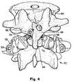
- FIG. 4is a posterior view of an artificial facet joint prosthesis installed in a patient according to one embodiment of this invention.
- FIG. 5is a left side view of the embodiment of FIG. 4 , as installed in a patient.
- FIG. 6is yet another view of the embodiment of FIG. 4 , as installed in a patient.
- FIG. 7Ais a cross-sectional view of a cephalad bearing element and fixation element according to the embodiment of FIG. 4 .
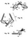
- FIG. 7Bis a posterior view of a pair of artificial cephalad and caudal facet joint prostheses according to one embodiment of this invention.
- FIG. 7Cis a top view of a pair of artificial cephalad and caudal facet joint prostheses in the embodiment of FIG. 7A .
- FIG. 7Dis a left view of a pair of artificial cephalad and caudal facet joint prostheses in the embodiment of FIG. 7A .
- FIG. 7Eis a bottom view of a pair of artificial cephalad and caudal facet joint prostheses in the embodiment of FIG. 7A .
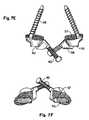
- FIG. 7Fis an anterior view of a pair of artificial cephalad and caudal facet joint prostheses in the embodiment of FIG. 7A .
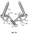
- FIG. 7Gis a bottom view of an alternate embodiment of a pair of artificial cephalad and caudal facet joint prostheses.
- FIG. 8Ais a perspective view of an installation fixture according to one embodiment of this invention.
- FIG. 8Bis a top view of the installation fixture of FIG. 8A .
- FIG. 8Cis a side view of the installation fixture of FIG. 8A .
- FIG. 8Dis a back view of the installation fixture of FIG. 8A .
- FIG. 9is an exploded view of the installation fixture of FIG. 8 along with a pair of caudal facet bearing elements and a pair of cephalad facet bearing elements according to one embodiment of the invention.
- FIGS. 10A-Dare views of a guide tool according to one embodiment of the invention.
- FIG. 11is a posterior view of the installation fixture of FIGS. 8 and 9 to which a pair of caudal facet bearing elements and a pair of cephalad bearing elements have been attached and with the caudal bearing elements attached to the patient.
- FIG. 12is a left side view of the installation fixture and bearing elements of FIG. 11 with the caudal bearing elements attached to the patient.
- FIG. 13is a perspective view of the installation fixture and bearing elements of FIGS. 11 and 12 showing a guide tool according to one embodiment of this invention.
- FIG. 14is a perspective view of the installation fixture and bearing elements of FIGS. 11 and 12 showing the use of a drill bit with the guide tool according to one embodiment of this invention.
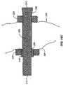
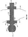
- FIGS. 15A and 15Bare a perspective and cross section views, respectively, of a cephalad prosthesis embodiment of the present invention.
- FIGS. 16A-16Dillustrate a method of implanting and securing the prosthesis of FIGS. 15A and 15B .
- FIG. 17is a left side perspective view of a pair of cephalad prosthesis embodiments constructed in accordance with the teachings of the present invention implanted into a vertebral body.
- FIG. 18is a right side perspective view of the cephalad prosthesis of FIG. 17 .
- FIG. 19is an elevated right side perspective view of the cephalad prosthesis of FIGS. 17 and 18 .
- FIG. 20is an elevated left side perspective view of the cephalad prosthesis of FIG. 17 .
- FIG. 21is a cross-sectional view of an alternative embodiment of a cephalad prosthesis constructed in accordance with the teachings of the present invention.
- FIG. 22is a cross-sectional view of the cephalad prosthesis of FIG. 21 with an associated bearing surface element.
- FIG. 23is a cross-sectional view of the cephalad prosthesis of FIG. 21 in a targeted vertebral body.
- FIG. 24is a cross-sectional view of the cephalad prosthesis and bearing surface element of FIG. 22 , in a targeted vertebral body before securing the bearing surface element.
- FIG. 25is a cross-sectional view of the cephalad prosthesis of FIG. 24 , showing placement of the bearing surface element in a locked or secured position.
- FIG. 25Ais a cross section view of the cephalad prosthesis of FIG. 25 with an alternative embodiment of a bearing surface element.
- FIG. 26is a cross-sectional view of the cephalad prosthesis of FIG. 25 , after securing the bearing surface element.
- FIG. 27is a cross-sectional view of the cephalad prosthesis of FIG. 26 , after removal of the bearing surface element.
- FIG. 28is a cross-sectional view of the cephalad prosthesis of FIG. 26 , showing an alternate re-attachment and placement of the bearing surface element.
- FIG. 29is a perspective view of a counter-torque wrench suitable for use with various embodiments of the present invention.
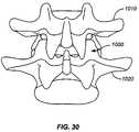
- FIG. 30is a side plan view of a functional spinal unit.
- FIG. 31is a side plan view of the functional spinal unit of FIG. 30 , after undergoing a decompressive laminectomy procedure.
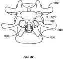
- FIG. 32is a side plan view of the functional spinal unit of FIG. 31 , after implantation of one embodiment of a caudal portion of a facet joint replacement prosthesis.
- FIG. 33is a side plan view of the functional spinal unit of FIG. 32 , after implantation of one embodiment of a cephalad portion of a facet joint replacement prosthesis.
- FIG. 34is a side plan view of the functional spinal unit of FIG. 32 , after implantation of another embodiment of a cephalad portion of a facet joint replacement prosthesis.
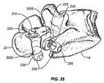
- FIG. 35is a perspective view of two reinforcing material embodiments of the present invention in place with embodiments of the cephalad prosthesis of FIG. 15A .
- FIGS. 4-7show artificial cephalad and caudal facet joint prostheses 36 and 50 (see FIG. 7C ) for replacing a natural facet joint according to one aspect of this invention.
- Cephalad prosthesis 36has a bearing element 38 with a bearing surface 40 .
- bearing surface 40has a convex shape.
- Bearing element 38may be formed from biocompatible metals (such as cobalt chromium steel, surgical steels, titanium, titanium alloys, tantalum, tantalum alloys, aluminum, etc.), ceramics, polyethylene, biocompatible polymers, and other materials known in the prosthetic arts
- bearing surface 40may be formed from biocompatible metals (such as cobalt chromium steel, surgical steels, titanium, titanium alloys, tantalum, tantalum alloys, aluminum, etc.), ceramics, polyethylene, biocompatible polymers, and other materials known in the prosthetic arts.
- the condition of the patient's natural facet jointmay not be acceptable and/or may need to be removed to access other spinal structures (such as the lamina and/or an intervertebral disc).
- spinal structuressuch as the lamina and/or an intervertebral disc.
- fixation element 42attaches cephalad prosthesis 36 to a vertebra 60 in an orientation and position that places bearing surface 40 in approximately the same location as the natural facet joint surface the prosthesis replaces.
- the prosthesismay also be placed in a location other than the natural facet joint location without departing from the invention, such as by orienting the fixation element along a different angle, by moving the joint cephalad/caudad, anteriorly/posteriorly, by moving the joint medially or laterally, or any combination thereof.
- fixation element 42is a screw.
- Other possible fixation elementsinclude headless screws, stems, posts, corkscrews, wire, staples, adhesives, bone cements, and other materials known in the prosthetic arts.
- the cephalad facet joint prosthesisattaches to a posterior element of the vertebra, such as one or more portions of the lamina and/or the spinous process.
- fixation element 42may extend through a lamina portion 62 of vertebra 60 at the base of spinous process 64 , traversing the vertebra midline as defined by the spinous process 64 and through another lamina portion 66 .
- This orientation of the fixation elementis similar to the orientation used to accomplish translaminar facet joint screw fixation, as known in the art.
- Other orientations of fixation element 42are possible, of course, depending on the dictates of the specific vertebral anatomy and the desires of the clinician.
- fixation element 42may extend through only one lamina portion, only through the spinous process, etc.
- this embodiment's use of one or more posterior elements of the vertebra to attach the cephalad facet joint prosthesis of this inventiondoes not block access to the pedicle area, leaving this area free to be used to attach other prostheses or devices.
- Other embodiments of the inventionmay occupy, block or impede access to the pedicle area, of course, without departing from the scope or spirit of the invention.
- the cephalad facet joint prosthesismay be affixed without the use of bone cement, especially when using a bone ingrowth surface, trabecular/coated metal or bioactive ceramics.
- fixation element's proximal end 43(preferably formed to mate with a suitable insertion tool) and distal end 44 lie on opposite sides of the lamina.
- Bearing element 38attaches to the distal end 44 of fixation element 42 to be disposed between a caudal facet joint bearing surface (either natural or artificial, such as the artificial caudal facet joint prosthesis described below) and a portion of the vertebra, such as the lamina portion shown in FIGS. 4-6 .
- a caudal facet joint bearing surfaceeither natural or artificial, such as the artificial caudal facet joint prosthesis described below
- a hole 46 in bearing element 38is formed with a Morse taper that mates with the distal end 44 of fixation element 42 .
- Other means of attaching bearing element 38 to fixation element 42may be used, of course, such as other Morse or other taper connections, machine screw threads, NPT screw threads or other known mechanical, physical (welding, etc.) or chemical fastening means.
- Fixation element 42may be coated with antimicrobial, antithrombotic, hydroxyapatite, osteoinductive and/or osteoconductive materials to promote bone ingrowth and fixation.
- Bearing element 38may be attached to fixation element 42 before or after implantation in the patient, depending on the manner of implantation and the requirements of the situation.
- Prosthesis 36may be used to form the cephalad portion of a facet joint with either a natural caudal facet joint portion or an artificial caudal facet joint prosthesis.
- FIGS. 4-7also show an artificial caudal joint prosthesis 50 for replacing the superior half of a natural facet joint according to one aspect of this invention.
- Caudal prosthesis 50has a bearing element 52 with a bearing surface 54 .
- bearing surface 54is concave (although the surface could be a myriad of shapes, including, but not limited to, convex, rounded, flattened, complex, and/or spherical bearing surfaces).
- Bearing element 52may be formed from biocompatible metals (such as cobalt chromium steel, surgical steels, titanium, titanium alloys, tantalum, tantalum alloys, aluminum, etc.), ceramics, polyethylene, biocompatible polymers, and other materials known in the prosthetic arts
- bearing surface 54may be formed from biocompatible metals (such as cobalt chromium steel, surgical steels, titanium, titanium alloys, tantalum, tantalum alloys, aluminum, etc.), ceramics, polyethylene, biocompatible polymers, and other materials known in the prosthetic arts.
- the natural caudal facet surfacehas been removed, and fixation element 56 attaches prosthesis 50 to a vertebra 70 via a pedicle in an orientation and position that places bearing surface 54 in approximately the same location as the natural facet joint surface the prosthesis replaces.
- the bearing surface 54may be placed in a location different than the natural facet joint surface, either more medial or more lateral, more cephalad or more caudad, more anterior or more posterior, and/or rotated or displaced from the natural anatomical orientation and orientation.
- the geometry and function of the artificial jointscould be designed to allow for greater-than-natural flexibility and/or movement, to account for motion missing and/or lost due to disease, injury, aging and/or fusion of the treated and/or other vertebral levels.
- the caudal componentcan be attached to other locations in or on the vertebral body in addition to the pedicle or to the vertebral body alone.
- fixation element 56is a screw attached to bearing element 54 via a hole 58 formed in bearing element 52 and is inserted into a pedicle portion 72 of vertebra 70 .
- Other possible fixation elementsinclude stems, posts, corkscrews, wire, staples, adhesives, clamps, hooks, bone cements, and other materials known in the prosthetic arts.
- the fixation element 56can also be inserted into the vertebral body (or portions of the lamina or spinous process) in addition to or in place of the pedicle.
- the fixation elementmay comprise some or all of the bearing surface.
- bearing element 52has a serrated fixation surface 57 adapted to contact a contact portion 74 of vertebra 70 .
- This optional fixation surface 57helps prevent rotation of the bearing element 52 .
- the fixation surface 57may be coated with bone ingrowth material, and any optional serrations can increase the surface area for bony ingrowth (as well as prevent unwanted rotation of the implant).
- the entire bearing surface 54is posterior to surface 57 and contact portion 74 .
- the bearing elements 52 and 38could incorporate an off-center peg or protrusion 56 a (See FIG.
- the cephalad and/or caudal componentscould include an auxiliary fastener or clip (not shown) which secures to or around a portion of the vertebral body to inhibit and/or prevent rotation and/or displacement of the caudal or cephalad component.
- one or more of the bearing elementscould comprise an artificial or natural (i.e., allograft, autograft, xenograft or other bone graft material) substance used to resurface the natural and/or degenerated facet surface.
- Prosthesis 50may be used to form the caudal portion of a facet joint with either a natural cephalad facet joint portion or an artificial cephalad facet joint prosthesis.
- an artificial cephalad facet joint portionmay be use in conjunction with either an natural or artificial caudal facet joint component.
- FIGS. 7A-Fshow an artificial facet joint prosthesis according to one embodiment of this invention apart from the vertebrae.
- cephalad bearing surface 40 and caudal bearing surface 54meet to form an artificial facet joint.
- the width of caudal bearing surface 54 along its transverse axisis desirably greater than the width of cephalad bearing surface 40 along its transverse axis. This feature helps align the cephalad and caudal joints during implant. In addition, this feature permits the point of contact between the two bearing surface to change with flexion, extension, left and right rotation and lateral bending of the patient's spine.
- the prosthesiscan be designed to mimic the natural motion and flexibility of the replaced facet joint, or can alternatively be tailored to accommodate a lesser or greater degree of flexibility and/or motion (to accommodate damaged tissues such as discs, etc., or to compensate for co-existing limitations on spinal motion such as existing spinal deformities and/or adjacent fused levels).
- FIGS. 4-7may be implanted without special tools.
- One embodiment of the inventionincludes an installation fixture to assist with the implantation procedure.
- FIGS. 8-14show installation tools used to implant two artificial facet joints, i.e., two cephalad facet joint prostheses and two corresponding caudal facet joint prostheses.
- the inventionalso includes installation tools for implanting a single facet joint prosthesis, two caudal facet joint prostheses, two cephalad facet joint prostheses, a caudal and cephalad joint prosthesis, or any other combination of facet joint prostheses.
- installation fixture 80has alignment elements 82 to align the cephalad bearing elements 38 and caudal bearing elements 52 .
- the alignment elementsare two dowels for each bearing element.
- Alignment elements 82mate with corresponding alignment elements in the bearing elements, such as holes 84 (shown, e.g., in FIG. 7B ) formed in cephalad bearing elements 38 and caudal bearing elements 52 .
- Other alignment elementsmay be used, of course, such as pins, grooves, indentations, etc.
- Attachment elementssuch as screws 86 attach the bearing elements 38 and 52 to the installation fixture via screw holes 88 (shown, e.g., in FIG. 7B ) formed in the bearing elements and in installation fixture 80 .
- cephalad and caudal bearing surfaces 40 and 54When attached to installation fixture 80 , cephalad and caudal bearing surfaces 40 and 54 are in contact and in proper alignment with respect to each other, as shown in FIG. 8 .
- the cephalad and caudal bearing surfaces 40 and 54are desirably “preloaded” and/or positioned to be in compression/contact when attached to installation fixture 80 .
- the components of the prosthesiscould be implanted while the joint structure is being distracted, or while the joint is held together either by the natural tissue or an artificial construct, or combination thereof.
- These bearing surfacescan desirably be positioned to either (1) come in contact with each other when the distraction is released, or (2) contact each other and be compressively loaded when the distraction is released.
- installation fixture 80has two bearing support components 90 and 92 that move in a controlled manner with respect to each other.
- a threaded shaft 94extends between support components 90 and 92 .
- Shaft 94engages bores formed in support components 90 and 92 ; one or both of the bores are threaded so that rotation of shaft 94 causes support components 90 and 92 to move towards or away from each other.
- Shaft 94may be provided with a thumbwheel 96 or other actuator for ease of use.
- One or more guide rods 98may be provided to maintain the alignment of support components 90 and 92 .
- Other means of moving the cephalad/caudal bearing elements pairs with respect to each othermay be used, such as a guided or unguided sliding connection between installation fixture elements.
- bearing elements 38 and 52are attached to installation fixture 80 as described above.
- the spacing between the bearing element pairsis then adjusted using thumbwheel 96 to align the fixation holes 58 of caudal bearing elements 52 with the proper fixation screw insertion sites in the pedicle portions of the caudal vertebra (or other suitable location), thus placing the artificial facet joints in positions corresponding to the position of natural facet joints or in any other position desired by the physician, including positions that do not correspond to the position of natural facet joints.
- Passages aligning with holes 58are formed in the pedicle—or into another part of the caudal vertebra near or adjacent to the pedicle—using a drill, awl, pedicle probe, or other tool known in the surgical arts. Fixation screws 56 are then inserted through holes 58 into the pedicle or other portion of the caudal vertebra to attach the caudal bearing elements as well as the entire prosthesis and installation fixture to the caudal vertebra 70 , as shown in FIGS. 11 and 12 . Alternatively, self-tapping screws or other caudal fixation elements may be used, thereby eliminating the need to pre-form the passages.
- cephalad bearing elementsare attached to the cephalad vertebra 60 .
- an insertion pathis first determined for each fixation element, then a passage is formed along the insertion path corresponding to cephalad bearing element holes 46 (e.g., in the lamina at the base of the spinous process and through the lamina on the other side, through only one lamina portion, through the spinous process, etc.).
- Fixation screws 42can then be inserted through the holes 46 into the passages.
- self-tapping screws or other caudal fixation elementsmay be used, thereby eliminating the need to pre-form the passages.
- Installation fixture 80may be detached and removed. Installation fixture 80 may be used to implant fewer than four bearing elements, of course.
- FIGS. 10 , 13 and 14show a tool that may be used to define the insertion path (location, orientation, etc.) for the fixation element of the left cephalad bearing element.
- the toolmay be used to guide the formation of a cephalad bearing element attachment passage for the left bearing element.
- a corresponding mirror image toolmay be used for the right cephalad bearing element.
- a single toolmay be used for defining the insertion path for both left and right cephalad bearing elements.
- tool 100has a handle 102 and an alignment interface (such as dowels 104 in tool 100 and holes 106 in fixture 80 ) to align the tool in the proper orientation with respect to installation fixture 80 and a cephalad facet joint bearing element.
- an alignment interfacesuch as dowels 104 in tool 100 and holes 106 in fixture 80
- the tool 100engages installation fixture through the alignment interface as shown in FIGS. 13 and 14 . In this position, the tool 100 may be used to define an insertion path for the cephalad fixation elements.
- the insertion path guideis a drill guide 108 supported by arms 110 and 112 and is aligned with the hole 46 in cephalad bearing element 38 by the alignment interface between installation fixture 80 and guide tool 100 .
- the drill guide 108is a tube, but other guide elements may be used, such as a guide groove or surface.
- the insertion path guidecould be an 11-gage spinal needle, or a cannula sized to accommodate the cephalad prosthesis components for a minimally invasive—MIV-procedure.
- a drill bit 114may be inserted through the drill guide 108 to form an insertion passage, such as a passage through a lamina portion of the cephalad vertebra.
- a fixation screwmay then be inserted through the passage in the cephalad vertebra and into the Morse taper connection of the hole 46 (or other type connection, as discussed above) of the cephalad bearing element 38 .
- the fixation screwmay be coated with a bone ingrowth material.
- a self-tapping screwmay be used, thereby removing the need to pre-form a passage.
- the proximal shaft of the drillcan include a drill-stop (not shown) to prevent advancement of the drill into the cannula beyond a desired depth.
- the proximal shaft of the drillcan include depth markings which, when the drill exits the passage, can be used to determine the length of the passage created in the lamina. Desirably, subtracting the length of the cannula (which is known) from the depth markings can provide an accurate estimate of the passage length, and thus assists the physician in the choice of the proper size cephalad implant to fill the passage.
- a mirror image toolmay then be used to define an insertion path or to form a hole for the right cephalad bearing element, which is then affixed to the vertebral body in the same way.
- the installation fixtureis then removed, such as by unscrewing screws 86 .
- the guide toolmay be used to define a path for a self-tapping screw or other fixation element that does not require the use of a drill.
- element 108may be used to define a path for the self-tapping screw or other fixation element.
- the fixation element pathmay be through only a single lamina portion, through the spinous process alone, or any other suitable path.
- the entire prosthesis other than the bearing surfacemay be coated with bone ingrowth material.
- FIGS. 15A and 15Bdepict a side plan and cross-sectional view, respectively, of an alternate embodiment of a cephalad portion of a facet replacement prosthesis constructed in accordance with the teachings of the present invention.
- the facet prosthesis 200comprises a substantially cylindrical body 205 having a proximal end 210 , a distal end 215 and an expanded section 250 adjacent the proximal end 210 .
- a proximal collar 220is adapted to secure against the proximal end, preferably against a portion of the expanded section 250 .
- a distal collar 225is secured about the body 205 in a position proximal to the distal end 215 .
- a ball 230incorporating one or more bearing surfaces 235 , is positioned at the distal end 215 .
- the ball 230is an example of a prosthetic bearing element adapted to form a part of an articulating process in the spine.
- the ball 230has an outer surface and an internal opening adapted to fit over the elongate body distal end. While the dimensions and specific design of the ball 230 and collars 220 , 225 may secure to the body 205 unaided, the illustrated embodiment of the prosthesis 200 includes a ball shim 240 to aid in securing the ball 230 into position on the body 205 , and a distal collar shim 245 to aid in securing the distal collar 225 into position on the body 205 .
- Non-circular cross section bodiesadvantageously provide the prosthesis an anti-rotation capability.
- features, compounds, or surface treatmentsmay be utilized to enhance attachment between the various components of the prosthesis 200 or between the prosthesis 200 and vertebral bone.
- portions of the collars 225 , 220 that interact with the body 205may be textured or have teeth to promote a stronger attachment when joined to the body 205 .
- portions of the collars 225 , 220 that come into contact with the lamina/spinous processmay also include features or surface textures to promote joining as well as compounds, for example, bone growth compounds or cements, to promote adhesion between the bone and the collars 220 , 225 .
- the surfaces of the shims 245 , 240may also include features or surface treatments to improve contact and grip between the distal collar 225 and the ball 230 , respectively, as well as the body 205 .
- the exterior surface of the body 205may also be adapted to include features, compounds, or surface treatments to improve contact with the shims 245 , 240 , collars 225 , 220 , ball 230 and the exposed bone in the passage 290 (see FIG. 16A ).
- the prosthesis 200has an elongated cylindrical body with a length of 40 mm, a minimum diameter of 4 mm, a distal end that expands to approximately 5 mm, and a ball 230 having a metal sphere with a diameter of approximately 10 mm.
- the size, length and dimensions of the components of prosthesis 200may vary and be selected based on a number of criteria. Examples of selection criteria include the age and sex of the patient, the specific pathology and anatomy of the patient and the specific spinal level where implantation will occur.
- the measurement techniques and tools described hereinmay be used to determine the size, dimensions and placement of a specific prosthesis 200 .
- a passage 290is formed completely through the remaining lamina and/or spinous process of the cephalad vertebra between a first outer surface of lamina and/or spinous process 285 and a second outer surface of lamina and/or spinous process 287 .
- the passage 290is adapted to accommodate the prosthesis 200 , specifically the body 205 ( FIG. 16A ).
- the passage 290is sized to accept the cylindrical body 205 but not the expanded section 250 .
- a proximal collar 220is slid over the distal end 215 of the body 205 .
- proximal collar 220is sized and shaped to engage with a portion of the expanded section 250 .
- the body 205is advanced distal end 215 first through the passage 290 until the proximal collar 220 abuts against the first outer surface of the lamina and/or spinous process 285 and the expanded section 250 .
- the distal collar 225slides over the distal end 215 , abutting against the second outer surface of the lamina and/or spinous process 287 .
- a distal collar shim 245is pushed between the body 205 and the distal collar 225 to secure the distal collar 225 in position.
- the distal collar 225 and the proximal collar 220are compressed and/or tightened against the outer surfaces of the lamina 285 , 287 , desirably against one or more cortical bone surface(s) of the lamina and/or spinous process.
- the ball shim 240 and bearing 230are advanced over the distal end 215 .
- the ball shim 240is used to wedge the bearing 230 into the desired position relative to the distal end 215 .
- a prosthesis 200 for replacing the opposing cephalad facet joint on the same vertebral bodycan be placed in a similar manner into a corresponding passage 290 through the lamina and/or spinous process resulting in two prosthesis per level as illustrated, for example, in the several views of FIGS. 17-20 .
- a pair of such prosthesis 200can be secured through the lamina and/or spinous process of a targeted vertebra to replace a pair of natural cephalad facet structures.
- the surgical proceduremay include, but is not limited to, the removal and/or resection of one or more sections of the lamina and cephalad/caudad facet joint structure to alleviate nerve compression and/or spinal stenosis, remove disease or damaged tissues, prepare the intervertebral disk space to receive an artificial disk replacement/augmentation prosthesis, provide access to spinal structures, or for other reasons.
- the targeted facet capsuleis initially exposed (the open portion) using standard open surgical techniques.
- the facet capsuleis then opened and/or removed, and the superior and/or inferior facets are resected and/or removed as necessary (using a surgical cutter or rongeur) during the surgical procedure. If replacement of the caudal facet section is deemed necessary, a caudal stem and associated caudal bearing can be implanted into the exposed pedicle through the open incision.
- a majority of the components of the prosthesis 200can be surgically implanted using minimally-invasive techniques alone or in combination with conventional open techniques.
- all or most of the prosthesis 200may be delivered through a cannula inserted through a small incision in the skin.
- the physiciancan first create an access path through the skin and soft tissue (with a spinal needle and/or K-wire) to the lamina of the targeted vertebral body.
- non-invasive visualizationsuch as fluoroscopic or real-time MRI
- tissue structuressuch as muscles, tendons, ligaments, nerves, veins and/or the spinal cord itself.
- a suitable cannulacan be advanced through the tissues to the targeted bone.
- progressively larger dilation catheterssuch as the AccessTM Dilation Port commercially available from Spinal Concepts of Austin, Tex.
- one cannulais positioned and adapted to deliver the body 205 and the proximal collar 220 and another cannula is positioned and adapted to deliver the remaining prosthesis components.
- a drillis advanced through the central opening in the cannula and drills into and through the targeted portion of the lamina and/or spinous process, creating a passage through the lamina.
- a positioning toolsuch as the tool 100 shown in FIGS. 10A-10D ) will be used to align the cannula and/or drill (and thus the passage created) such that the passage is aligned to permit the bearing surface of the cephalad implant to mate with the corresponding caudal bearing surface.
- the position of the drill tipcan be visually verified (as the drill tip exits the lamina) through the open incision.
- the positioning toolaligns the cannula and/or drill relative to the caudal bearing surface. In another alternate embodiment, the positioning tool aligns the cannula and/or drill relative to the upper endplate of the caudal vertebral body, either prior, during, or after the initial access through the patient's skin and/or during the surgical procedure.
- the drill(and any alignment frame, if desired) is removed (with the cannula desirably remaining in place in the patient), and the cylindrical body 205 and associated proximal collar 220 are advanced through the cannula and into the passage 290 in the lamina.
- the proximal collar 220is desirably seated against the near surface of the lamina (i.e., the first outer surface of the lamina or spinous process 285 ), with the distal end 215 extending out of the far surface of the lamina into the open incision (i.e., beyond the second outer surface of the lamina or spinous process 287 .)
- the distal collar 225 and shim 245are then placed on the distal end 215 and tightened into position as described above. Desirably, the distal and proximal collars 225 , 220 will compress and bear directly against the far and near outer surfaces of the lamina and/or spinous process 285 , 287 , with the lamina and/or spinous process in between.
- the ball 230is positioned over the distal end 215 into the desired position and secured using the shim 240 as previously described.
- the open surgical sitecan be closed in a known manner, and the surgical procedure completed.
- various embodiment of the caudal and/or cephalad components disclosed hereincould incorporate non-circular posts or stems for anchoring the devices. Passages to accommodate such constructs could be created using broachers, reamers, awls, punches or the like. Such non-circular stems would desirably reduce and/or prevent unwanted rotation of these components along their longitudinal axis.
- FIG. 21depicts an alternate embodiment of the present invention constructed in accordance with the teachings of the present invention. Because many features of this embodiment are similar to components previously-described in connection with other embodiments, like reference numerals will be used to describe similar components.
- the cephalad prosthesis 200 acomprises a substantially cylindrical hollow body 205 a having a proximal end 210 a , a distal end 215 a and a longitudinally-extending bore 207 a there through.
- the body 205 a exteriorhas an enlarged outer ridge 217 a , and a wrench-engagement section 209 a positioned near the proximal end 210 a .
- the size, shape, and contours of the enlarged outer ridge 217 aare adapted to engage with the proximal collar 220 a (e.g., FIG. 23 ).
- the outer or engagement surfaces of the ridge 217 a and/or collar 220 amay include features, surface treatment or compounds as described herein or known to those of ordinary skill in the prosthetic arts to improve joining between those components or adjacent bone.
- a cylindrical shaft 250 aextending through the bore 207 a and sized to permit relative movement therein, has a set of external threads 255 a which mate with corresponding internal threads 260 a inside the bore 207 a .
- the shaft 250 ahas a proximal drive section 270 a , a revision drive section 275 a and a notched link 280 a there between.
- the shaft 250 aincludes an enlarged distal plug 265 a sized and adapted to deform the distal end 215 a when advanced proximally relative to the body 205 a via engagement of threads 255 a , 260 a .
- FIG. 22 and 23illustrate an embodiment of a bearing 235 a having an aperture 233 sized to fit over distal end 215 a .
- the prosthetic bearing 235 ais an example of a bearing element adapted to form a part of an articulating process in the spine.
- the bearing 235 ais illustrated adjacent ( FIG. 23 ) and in position over the distal end 215 a ( FIG. 22 , 24 ) before proximal advancement of the distal plug 265 a .
- the plug 265 adeforms the distal end 215 a into pressing contact with the surfaces of the aperture 233 locking the bearing 235 a in place ( FIG. 25 ).
- a passage 305 ais drilled completely through the lamina and/or spinous process from a first outer surface 385 to a second outer surface 387 of a lamina and/or spinous process as previously described (the passage 305 a is illustrated in FIG. 23 ).
- the physicianwill choose and form the passage 305 a based on the condition of the lamina, the patient's specific anatomy, the physician's knowledge of anatomy, and the desired final location of the cephalad bearing surface relative to the vertebral body.
- the physiciancan initially place a caudal bearing surface, and then use a jig or other tool to determine the desired orientation and position of the passage that must be created to implant a cephalad prosthesis that properly mates with the caudal bearing surface.
- the physicianwill slide a proximal collar 220 a over the distal end 215 a up to engagement with the exterior surface of the ridge 217 a .
- the body 205 ais then advanced distal end 215 a first until the proximal collar 220 a seats against the first outer surface of the lamina and/or spinous process 385 and the distal end 215 a desirably extends out of the other end of the passage 305 a (i.e., beyond the second outer surface of the lamina and/or spinous process 387 ) ( FIG. 23 ).
- the distal end 215 awould extend into the open surgical space while the first outer surface 385 was accessed and the passage 305 a was formed using minimally invasive techniques as described herein or known to those of ordinary skill in the surgical arts.
- a distal collar 225 ais advanced over the body distal end 215 a until the collar 225 a contacts the second outer surface of the lamina and/or spinous process 387 .
- a shim or wedgeas described above with shims 240 , 245 , may be driven between the distal collar 225 a and the body 205 a to secure the distal collar 225 into position.
- the bearing 235 ais advanced such that the distal end 215 a is disposed within the aperture 233 .
- the bearing 235 ais advanced over the distal end 215 a until the inner surface 310 a of the bearing 235 a abuts against the body distal end 215 a . It is to be appreciated that the bearing 235 a may, depending upon a number of factors such as patient anatomy and relationship to other prosthetic components, engage the distal end 215 a in a position other than against the inner surface 310 a (e.g., FIG. 28 ). Alternatively as shown in FIG. 25A , an opening 233 a may extend completely through a bearing 235 b.
- the physiciancan utilize a counter-torque wrench 400 (see FIG. 29 ) having a rotating driver section 420 which engages the proximal drive section 270 a of the shaft 250 a , and a stationary driver section 410 which engages the wrench-engagement section 209 a of the body 205 a .
- the wrench 400rotates the drive section 270 a relative to the wrench-engagement section 209 a with little or no movement of the prosthesis relative to the lamina.
- This rotationwill desirably draw the enlarged distal plug 265 a further into the distal end 215 a of the body 205 a , causing the distal end 215 a to expand outward and wedging (and securing) the bearing 230 a to the body 205 a ( FIG. 25 ).
- the bearingcan also secure the distal collar 225 a against the lamina, rather than by using a shim or wedge to secure the collar 225 a.
- the end of the wrench 400can include a detent section (or other type of catching or holding mechanism—not shown) which desirably contains the sheared section of the shaft 250 a.
- implantation of a similar cephalad prosthesis corresponding to the complimentary facet jointcan be accomplished in a like manner.
- the present embodimentalso facilitates revision/removal of the cephalad prosthesis.
- the counter-torque wrench 400can be used to rotate the shaft 250 a (relative to the body 205 a ) in a direction opposite to the “tightening direction”, thereby advancing the shaft 250 a distally and eventually “pushing” the bearing 230 a off of the distal end 215 a of the body 205 a ( FIG. 27 ).
- removal of the bearing 230 awill also compress the distal end 215 a of the body 205 a to some extent, simplifying removal of the distal collar 225 a as well as withdrawal of the body 205 a proximally through the passage 305 a and ultimately from the treatment site (if so desired).
- the caudal bearing surface(or both surfaces) could be repaired and/or replaced and/or repositioned if desired and/or necessary ( FIG. 28 ).
- the previously-described procedurecould similarly be used to replace a worn and/or damaged bearing surface of a previously-implanted cephalad construct, without requiring removal and/or revision of the entire cephalad implant. Simply removing and replacing the worn or damaged bearing with a new/undamaged bearing, and retightening of the cephalad implant, could be accomplished with little or no disruption to the surrounding tissues. Moreover, such a repair procedure could be accomplished using a first cannula to access the proximal drive section 270 a and associated components, and a second cannula to access the bearing 230 a (to remove the old bearing and introduce a new replacement).
- the bearing surfaces 235 , 235 a of the bearings 230 , 230 acould be non-spherical (including oval, square, triangular, flattened and/or disk shaped), and could include one or more bearing surfaces 235 ( i .e., more than one bearing surface 235 as illustrated in FIG. 15A ).
- the present embodimentcan facilitate the repair and replacement/augmentation of the facet joints in a minimally-invasive, limited-open (or modified-open) and/or fully-open surgical procedure.
- a minimally-invasive, limited-open (or modified-open) and/or fully-open surgical procedureFor example, where facet joint replacement is deemed necessary, but removal of soft and/or hard tissues in and/or adjacent the spinal canal is not warranted or desired (such as where spinal stenosis and nerve impingement is not a significant concern), the repair and/or replacement of one or more facet joints can be accomplished in a least-invasive fashion, using one or more cannulae to implant the prosthesis and associated distal hardware.
- such a procedurecan be accomplished through a combination of open, semi-open and/or minimally invasive procedures (which will be referred to herein as a modified-open or mini-open procedure) to minimize damage and/or disruption to surrounding soft-tissue structures.
- open, semi-open and/or minimally invasive procedureswhich will be referred to herein as a modified-open or mini-open procedure
- one or more of the facet joint capsulescan be exposed through an open incision (to allow easy resection and removal of the facet joint and/or surrounding anatomical structures), and the cephalad component of the facet replacement can be delivered through the lamina through a cannula or other minimally-invasive delivery method.
- cephalad prosthesisis positioned within the lamina, with only limited portions of the implant extending outwards from the vertebral body.
- This arrangementpresents a low-profile to the surrounding soft tissue structures, desirably resulting in less interaction between the prosthesis and the surrounding soft tissues, as well as less displacement of natural tissues due to the presence of the implant.
- anchoring the cephalad portion of the prosthesis within the lamina and/or spinous processreduces and/or eliminates to opportunity for unwanted contact between the dura and the prosthesis.
- kits including the cephalad implantcan include cephalad implants having various lengths, including 30, 40, 50 and 60 millimeters, to accommodate passages/lamina having differing lengths/thicknesses.
- the depth of the hole 233 in the bearing 235 a(to accommodate the distal end of the cephalad component) can vary (by 1 or 1 ⁇ 2 mm increments, for example) to accommodate anatomical variations in the patient.
- the present embodiment and implantation methodsreduces the need for a highly-modular and/or configurable cephalad prosthesis.
- the present implant designcan accommodate bones of varying dimensions and/or configurations.
- the solid nature of the componentretains its strength and durability.
- the present embodiment(1) reduces the opportunity for unintended damage to and/or intrusion into the facet joint capsule and facet joint structures of the cephalad vertebral level being treated, (2) allows for subsequent or concurrent implantation of additional prosthesis into the pedicles of the cephalad vertebral body, (3) allows unrestricted access to the intervertebral disk and disk structures in event of the need for concurrent or subsequent disk treatment, and (4) utilizes the lamina (and thus the pedicles) to support the prosthesis in a more natural anatomical manner.
- the present embodimentwill permit a physician to “daisy-chain” multiple prosthesis along multiple vertebral levels, during either a single surgical procedure or during subsequent surgeries as additional facet joints degrade and/
- the present embodimentBy anchoring the cephalad prosthesis within the lamina and/or spinous process, rather than within the pedicle, the present embodiment more closely mimics the natural anatomical position and loading of the cephalad facet joint surface and vertebral bodies. Loads which would have originally been transmitted from the inferior facet joint through the lamina and pedicles and into the vertebral body (which would be directly conducted through the pedicle and into the vertebral body by a pedicle-based cephalad implant anchoring system) are now simply transferred through the cephalad prosthesis and into the lamina in a more natural anatomical loading manner. Moreover, the use of the lamina as an anchoring point for the implant significantly reduces the forces experienced by the bone at the anchor (desirably reducing the tendency for the implant to break or loosen over time).
- the proximal and distal collarscan move and/or rotate to a limited degree relative to the cylindrical body of the cephalad implant, such that, when the implant is in position and tightened, the collars will lie relatively flat against the cortical bone walls of the lamina at either or both the proximal and distal ends of the cephalad implant.
- the physiciancan alter one or both sides of the lamina to more readily accommodate the proximal and/or distal collars.
- the cephalad stemswill be secured directly to the lamina and will incorporate a bony-ingrowth surface.
- the stemscan be secured to the lamina using bone-cement or osteo-conductive or osteo-inductive material.
- any such securing materialwill resist progressive loosening and fracture propagation typically associated with long-term implantation of orthopedic joint replacements.
- the lamina passagescould cross through each other, with the bodies of the individual cephalad prosthesis connecting or “linking in one or more manner (either inside the lamina or externally to the lamina, or some combination thereof) to more securely “solidify” the fixation and rigidity of the construct.
- one cephalad implantcould incorporate a through-hole of varying size to accommodate a corresponding distal end of a corresponding implant.
- the implantscould be bridged by a locking collar extending over, under and/or through the spinous process.
- the cephalad implant or portions thereofcan be non-cylindrical, and the correspondingly shaped passage through the lamina can be created using a chisel, rongeur, broach or “box punch”.
- a non-cylindrical implantwould desirably resist rotation to a significant degree.
- the cephalad and caudal components of the prosthesiscan be linked together to reduce and/or eliminate relative motion between the cephalad and caudal components, and thus between the cephalad and caudal vertebral bodies.
- the cephalad componentscan be “capped” or locked to the caudal components.
- Such linking mechanismcould include clamps or wraps (such as wire ties) which secure the bearing surface within the caudal cup, as well as adhesives which could secure the components to each other or “fill” a clamp or cup used to “fuse” the articulating surfaces of the implant.
- the bearing 235 aneed not be positioned flush against the distal end 215 a , but can rather be secured to the body 205 a at various locations, thereby incorporating some length variability into the system ( FIG. 28 ).
- the distal collar 225 a and wedge (if used)can be secured to various positions along the body 205 a .
- the proximal collar 220 acan incorporate an offset through-hole (such as a 15′ offset or a 30′ offset from perpendicular) to accommodate even greater angular variability in the first outer surface of the lamina 385 relative to the passage 305 a . Similar variations are possible for the components in embodiments of prosthesis 200 .
- FIGS. 30 through 34depict other alternate embodiments of facet joint replacement prostheses constructed in accordance with the teachings of the present invention.
- FIG. 30illustrates a superior vertebral body 1010 , an inferior vertebral body 1020 and a functional spinal unit 1000 (i.e., a pair of facet joints) between the bodies 1010 , 1020 .
- a portion of the superior vertebral body 1010 and the functional spinal unit 1000has been removed during a decompressive laminectomy procedure.
- some or all of the posterior portions of one or more vertebral bodiesmay be damaged or removed, or the area may be weakened by degeneration and/or disease, rendering them unsuitable for anchoring a portion of the prosthesis into and/or through the lamina.
- embodiments of the present inventionmay be adapted to attach to different portions of the vertebral body that remain structurally sound.
- a portion of the prosthesisin this embodiment the caudal portion 1030 of the prosthesis, can be anchored into the lamina of the inferior vertebral level 1030 .
- the superior vertebral body 1010has a compromised laminar structure.
- the other portion of the prosthesishere the cephalad portion 1040 in FIG. 33 , is anchored into the pedicles of the superior vertebral body 1010 .
- the cephalad and caudal portions 1040 and 1030articulate with respect to each other through the interactions of one or more bearing surfaces.
- FIG. 33illustrates an embodiment where the caudal prosthesis 1630 has a bearing surface 1035 that interacts with the cephalad bearing 1045 .
- the bearing surface 1035is on an anterior surface of the caudal prosthesis 1030 in the illustrated view.
- FIG. 34illustrates another alternative embodiment where the caudal bearing surface 1036 is on a posterior surface of the caudal prosthesis 1030 to interact with the cephalad bearing 1045 .
- both the cephalad and caudal portions of the prosthesiscould be secured to the lamina and/or spinous process of their respective vertebral bodies using embodiments of the present invention described above with regard to FIGS. 15-28 .
- Advantageously utilizing the lamina and/or spinous process of each vertebrapreserves the pedicles of both the cephalad and caudal vertebral levels for future treatment, permit treatment of a level involving previously-existing pedicular fixation, and/or allow treatment of an unfused level bounded by one or more upper and/or lower adjacent fused levels.
- FIG. 35illustrates other embodiments of prostheses 200 in place on a vertebral body 14 .
- FIG. 35illustrates reinforcing materials 3500 and 3505 disposed between collars 225 and 220 and the vertebral bone.
- the reinforcing material 3500 and 3505is desirably “wider” than the adjacent collars and assists in the distribution of the compressive load from the collars to a larger area of the vertebra.
- These reinforcing materialsare formed from any suitable material to distribute such loading, and may be malleable enough to be formed around and contour with the bone (while strong enough to distribute compressive loads), semi-malleable or rigid (and may comprise one or more series of different size and/or shape devices that correspond to varying anatomy of the targeted vertebral body).
- the reinforcing materialcan be formed from or is coated with a biocompatible coating or has a surface in contact with bone that is treated with compounds to promote adhesion to the bone or bone growth.
- the reinforcing materialis a strip 3500 desirably having sufficient length to extend from the proximal collar 220 , along the bone to the distal collar 225 .
- the reinforcing materialis one or more pads having a larger area than the adjacent collar.
- the reinforcing material 3505is shown adjacent a distal collar 225 (a similar reinforcing material may be placed adjacent the opposite proximal collar, if desired, which is hidden by the lamina in this figure.
- the reinforcing materialcould be used in conjunction with or in lieu of one or both collars 225 , 220 .
- the various disclosed embodimentscan facilitate the implantation of one or more portions of a facet joint prosthesis into a vertebral level that, for a myriad of reasons, cannot accommodate a pedicle-fixation based anchor.
- Such reasonscan include where the pedicular space is already occupied (i.e., where pedicle screws are being used in fusion systems and/or dynamic stabilization), is blocked (i.e. where existing hooks and/or rods block clear access to the pedicle), or where the vertebral body is partially or fully occupied to preclude introduction of pedicle anchors (i.e. where fixation screws for thoraco-lumbar plates pass in front of the pedicle space, or the vertebral body incorporates interbody spacers such as in the K-Centrum Anterior Spinal SystemTM).
- the caudal and cephalad bearing surfaces in other embodimentscould be reversed, such that the bearing surface of the caudal component could ride inside and/or against a bearing surface of the cephalad component.
- one or more balls (incorporating convex bearing surfaces) carried by the caudal componentscould ride inside one or more corresponding cups (incorporating concave bearing surfaces) carried by the cephalad components.
- the arms of the caudal componentscould be longer than the arms of the corresponding cephalad components.
- the disclosed pairs of caudal and cephalad portions of the facet replacement prosthesis described hereincould comprise a single caudal and cephalad pair, or more than two caudal and cephalad pairs.
- the disclosed caudal paircould comprise a single caudal portion, with one or a plurality of cephalad portions, and vice versa.
- the plurality of portionscould interact with a single bearing surface on the corresponding single portion, or multiple bearing surfaces on the corresponding single portion of the prosthesis.
- bearing surface 235 ais spherical in shape
- the bearing surface 235 acould be a myriad of shapes, including other geometric configurations as well as flat, convex or concave surfaces.
- the bearing surfacecould comprise a relatively flat surface having a convex face, similar to the surface of the facet joint it replaces.
Landscapes
- Health & Medical Sciences (AREA)
- Orthopedic Medicine & Surgery (AREA)
- Engineering & Computer Science (AREA)
- Biomedical Technology (AREA)
- Life Sciences & Earth Sciences (AREA)
- Animal Behavior & Ethology (AREA)
- Veterinary Medicine (AREA)
- Public Health (AREA)
- Transplantation (AREA)
- General Health & Medical Sciences (AREA)
- Oral & Maxillofacial Surgery (AREA)
- Heart & Thoracic Surgery (AREA)
- Vascular Medicine (AREA)
- Cardiology (AREA)
- Neurology (AREA)
- Surgery (AREA)
- Physical Education & Sports Medicine (AREA)
- Dentistry (AREA)
- Nuclear Medicine, Radiotherapy & Molecular Imaging (AREA)
- Medical Informatics (AREA)
- Molecular Biology (AREA)
- Prostheses (AREA)
Abstract
Description
Claims (7)
Priority Applications (9)
| Application Number | Priority Date | Filing Date | Title |
|---|---|---|---|
| US10/973,834US7608104B2 (en) | 2003-05-14 | 2004-10-25 | Prostheses, tools and methods for replacement of natural facet joints with artifical facet joint surfaces |
| PCT/US2005/015347WO2005107655A2 (en) | 2003-05-14 | 2005-05-02 | Prostheses, tools and methods for replacement of natural facet joints with artifial facet joint surfaces |
| EP05745561AEP1755499B1 (en) | 2003-05-14 | 2005-05-02 | Prostheses for replacement of natural facet joints with artifial facet joint surfaces |
| CA002563977ACA2563977A1 (en) | 2003-05-14 | 2005-05-02 | Prostheses, tools and methods for replacement of natural facet joints with artifial facet joint surfaces |
| AU2005240129AAU2005240129A1 (en) | 2003-05-14 | 2005-05-02 | Prostheses, tools and methods for replacement of natural facet joints with artifial facet joint surfaces |
| AT05745561TATE514397T1 (en) | 2004-05-03 | 2005-05-02 | PROSTHESIS FOR REPLACING NATURAL FACET JOINTS WITH ARTIFICIAL FACET JOINT SURFACES |
| US12/027,899US9198766B2 (en) | 2003-05-14 | 2008-02-07 | Prostheses, tools, and methods for replacement of natural facet joints with artificial facet joint surfaces |
| US13/771,881US9320547B2 (en) | 2004-08-18 | 2013-02-20 | Adjacent level facet arthroplasty devices, spine stabilization systems, and methods |
| US15/071,328US10098671B2 (en) | 2004-08-18 | 2016-03-16 | Adjacent level facet arthoroplasty devices, spine stabilization systems, and methods |
Applications Claiming Priority (3)
| Application Number | Priority Date | Filing Date | Title |
|---|---|---|---|
| US10/438,294US20040230304A1 (en) | 2003-05-14 | 2003-05-14 | Prostheses, tools and methods for replacement of natural facet joints with artifical facet joint surfaces |
| US56793304P | 2004-05-03 | 2004-05-03 | |
| US10/973,834US7608104B2 (en) | 2003-05-14 | 2004-10-25 | Prostheses, tools and methods for replacement of natural facet joints with artifical facet joint surfaces |
Related Parent Applications (1)
| Application Number | Title | Priority Date | Filing Date |
|---|---|---|---|
| US10/438,294Continuation-In-PartUS20040230304A1 (en) | 2003-05-14 | 2003-05-14 | Prostheses, tools and methods for replacement of natural facet joints with artifical facet joint surfaces |
Related Child Applications (1)
| Application Number | Title | Priority Date | Filing Date |
|---|---|---|---|
| US12/027,899DivisionUS9198766B2 (en) | 2003-05-14 | 2008-02-07 | Prostheses, tools, and methods for replacement of natural facet joints with artificial facet joint surfaces |
Publications (2)
| Publication Number | Publication Date |
|---|---|
| US20050143818A1 US20050143818A1 (en) | 2005-06-30 |
| US7608104B2true US7608104B2 (en) | 2009-10-27 |
Family
ID=34704000
Family Applications (2)
| Application Number | Title | Priority Date | Filing Date |
|---|---|---|---|
| US10/973,834Active2026-09-14US7608104B2 (en) | 2003-05-14 | 2004-10-25 | Prostheses, tools and methods for replacement of natural facet joints with artifical facet joint surfaces |
| US12/027,899Active2027-06-05US9198766B2 (en) | 2003-05-14 | 2008-02-07 | Prostheses, tools, and methods for replacement of natural facet joints with artificial facet joint surfaces |
Family Applications After (1)
| Application Number | Title | Priority Date | Filing Date |
|---|---|---|---|
| US12/027,899Active2027-06-05US9198766B2 (en) | 2003-05-14 | 2008-02-07 | Prostheses, tools, and methods for replacement of natural facet joints with artificial facet joint surfaces |
Country Status (5)
| Country | Link |
|---|---|
| US (2) | US7608104B2 (en) |
| EP (1) | EP1755499B1 (en) |
| AU (1) | AU2005240129A1 (en) |
| CA (1) | CA2563977A1 (en) |
| WO (1) | WO2005107655A2 (en) |
Cited By (32)
| Publication number | Priority date | Publication date | Assignee | Title |
|---|---|---|---|---|
| US20070149983A1 (en)* | 2005-12-13 | 2007-06-28 | Deru Gmbh | Facet joint prosthesis |
| US20080103501A1 (en)* | 2006-08-11 | 2008-05-01 | Ralph Christopher R | Angled Washer Polyaxial Connection for Dynamic Spine Prosthesis |
| US20080249568A1 (en)* | 2004-10-25 | 2008-10-09 | Kuiper Mark K | Crossbar Spinal Prosthesis Having a Modular Design and Systems for Treating Spinal Pathologies |
| US20100280551A1 (en)* | 2009-04-29 | 2010-11-04 | Ellipse Technologies, Inc. | Interspinous process device and method |
| US20120029573A1 (en)* | 2005-02-22 | 2012-02-02 | Triplett Daniel J | Polyaxial Orthopedic Fasteneing Apparatus with Independent Locking Modes |
| US8652137B2 (en) | 2007-02-22 | 2014-02-18 | Spinal Elements, Inc. | Vertebral facet joint drill and method of use |
| US20140100610A1 (en)* | 2007-01-10 | 2014-04-10 | Gmedelaware 2 Llc | System and Method for Facet Joint Replacement |
| US8740942B2 (en) | 2004-02-06 | 2014-06-03 | Spinal Elements, Inc. | Vertebral facet joint prosthesis and method of fixation |
| US8740949B2 (en) | 2011-02-24 | 2014-06-03 | Spinal Elements, Inc. | Methods and apparatus for stabilizing bone |
| USD724733S1 (en) | 2011-02-24 | 2015-03-17 | Spinal Elements, Inc. | Interbody bone implant |
| US8992533B2 (en) | 2007-02-22 | 2015-03-31 | Spinal Elements, Inc. | Vertebral facet joint drill and method of use |
| US8998968B1 (en) | 2012-11-28 | 2015-04-07 | Choice Spine, Lp | Facet screw system |
| US9271765B2 (en) | 2011-02-24 | 2016-03-01 | Spinal Elements, Inc. | Vertebral facet joint fusion implant and method for fusion |
| US9358122B2 (en) | 2011-01-07 | 2016-06-07 | K2M, Inc. | Interbody spacer |
| US9421044B2 (en) | 2013-03-14 | 2016-08-23 | Spinal Elements, Inc. | Apparatus for bone stabilization and distraction and methods of use |
| USD765853S1 (en) | 2013-03-14 | 2016-09-06 | Spinal Elements, Inc. | Flexible elongate member with a portion configured to receive a bone anchor |
| US9451990B2 (en)* | 2004-02-17 | 2016-09-27 | Globus Medical, Inc. | Facet joint replacement instruments and methods |
| US9456855B2 (en) | 2013-09-27 | 2016-10-04 | Spinal Elements, Inc. | Method of placing an implant between bone portions |
| US20170056207A1 (en)* | 2004-04-22 | 2017-03-02 | Globus Medical, Inc. | Implantable orthopedic device component selection instrument and methods |
| USD790062S1 (en) | 2011-10-26 | 2017-06-20 | Spinal Elements, Inc. | Interbody bone implant |
| US9820784B2 (en) | 2013-03-14 | 2017-11-21 | Spinal Elements, Inc. | Apparatus for spinal fixation and methods of use |
| US9839450B2 (en) | 2013-09-27 | 2017-12-12 | Spinal Elements, Inc. | Device and method for reinforcement of a facet |
| US9839451B2 (en) | 2016-03-29 | 2017-12-12 | Christopher D. Sturm | Facet joint replacement device and methods of use |
| US9931142B2 (en) | 2004-06-10 | 2018-04-03 | Spinal Elements, Inc. | Implant and method for facet immobilization |
| US10702313B1 (en)* | 2017-09-11 | 2020-07-07 | NuTech Spine, Inc. | Facet buttress implant and method of using same |
| US10758361B2 (en) | 2015-01-27 | 2020-09-01 | Spinal Elements, Inc. | Facet joint implant |
| US11304733B2 (en) | 2020-02-14 | 2022-04-19 | Spinal Elements, Inc. | Bone tie methods |
| US11457959B2 (en) | 2019-05-22 | 2022-10-04 | Spinal Elements, Inc. | Bone tie and bone tie inserter |
| US11464552B2 (en) | 2019-05-22 | 2022-10-11 | Spinal Elements, Inc. | Bone tie and bone tie inserter |
| US11478275B2 (en) | 2014-09-17 | 2022-10-25 | Spinal Elements, Inc. | Flexible fastening band connector |
| US12369952B2 (en) | 2021-12-10 | 2025-07-29 | Spinal Elements, Inc. | Bone tie and portal |
| US12440242B2 (en) | 2024-04-29 | 2025-10-14 | Spinal Elements, Inc. | Flexible fastening band connector |
Families Citing this family (85)
| Publication number | Priority date | Publication date | Assignee | Title |
|---|---|---|---|---|
| US7674293B2 (en) | 2004-04-22 | 2010-03-09 | Facet Solutions, Inc. | Crossbar spinal prosthesis having a modular design and related implantation methods |
| US7691145B2 (en) | 1999-10-22 | 2010-04-06 | Facet Solutions, Inc. | Prostheses, systems and methods for replacement of natural facet joints with artificial facet joint surfaces |
| ATE285207T1 (en) | 1999-10-22 | 2005-01-15 | Archus Orthopedics Inc | FACET ARTHROPLASTY DEVICES |
| US8187303B2 (en) | 2004-04-22 | 2012-05-29 | Gmedelaware 2 Llc | Anti-rotation fixation element for spinal prostheses |
| US6579319B2 (en)* | 2000-11-29 | 2003-06-17 | Medicinelodge, Inc. | Facet joint replacement |
| US20050080486A1 (en) | 2000-11-29 | 2005-04-14 | Fallin T. Wade | Facet joint replacement |
| US6419703B1 (en) | 2001-03-01 | 2002-07-16 | T. Wade Fallin | Prosthesis for the replacement of a posterior element of a vertebra |
| US6565605B2 (en) | 2000-12-13 | 2003-05-20 | Medicinelodge, Inc. | Multiple facet joint replacement |
| US7090698B2 (en) | 2001-03-02 | 2006-08-15 | Facet Solutions | Method and apparatus for spine joint replacement |
| AU2003265597A1 (en)* | 2002-08-23 | 2004-03-11 | Paul C. Mcafee | Metal-backed uhmpe rod sleeve system preserving spinal motion |
| US7608104B2 (en) | 2003-05-14 | 2009-10-27 | Archus Orthopedics, Inc. | Prostheses, tools and methods for replacement of natural facet joints with artifical facet joint surfaces |
| US20040230304A1 (en) | 2003-05-14 | 2004-11-18 | Archus Orthopedics Inc. | Prostheses, tools and methods for replacement of natural facet joints with artifical facet joint surfaces |
| US7074238B2 (en) | 2003-07-08 | 2006-07-11 | Archus Orthopedics, Inc. | Prostheses, tools and methods for replacement of natural facet joints with artificial facet joint surfaces |
| WO2005009299A1 (en)* | 2003-07-25 | 2005-02-03 | Impliant Ltd. | Elastomeric spinal disc nucleus replacement |
| US7909869B2 (en) | 2003-08-05 | 2011-03-22 | Flexuspine, Inc. | Artificial spinal unit assemblies |
| US7753958B2 (en) | 2003-08-05 | 2010-07-13 | Gordon Charles R | Expandable intervertebral implant |
| US7799082B2 (en) | 2003-08-05 | 2010-09-21 | Flexuspine, Inc. | Artificial functional spinal unit system and method for use |
| US9254137B2 (en)* | 2003-08-29 | 2016-02-09 | Lanterna Medical Technologies Ltd | Facet implant |
| US7588590B2 (en) | 2003-12-10 | 2009-09-15 | Facet Solutions, Inc | Spinal facet implant with spherical implant apposition surface and bone bed and methods of use |
| US20050131406A1 (en) | 2003-12-15 | 2005-06-16 | Archus Orthopedics, Inc. | Polyaxial adjustment of facet joint prostheses |
| US8562649B2 (en) | 2004-02-17 | 2013-10-22 | Gmedelaware 2 Llc | System and method for multiple level facet joint arthroplasty and fusion |
| US7051451B2 (en) | 2004-04-22 | 2006-05-30 | Archus Orthopedics, Inc. | Facet joint prosthesis measurement and implant tools |
| US7914556B2 (en) | 2005-03-02 | 2011-03-29 | Gmedelaware 2 Llc | Arthroplasty revision system and method |
| US7338527B2 (en)* | 2004-05-11 | 2008-03-04 | Geoffrey Blatt | Artificial spinal disc, insertion tool, and method of insertion |
| US8764801B2 (en)* | 2005-03-28 | 2014-07-01 | Gmedelaware 2 Llc | Facet joint implant crosslinking apparatus and method |
| US7507242B2 (en) | 2004-06-02 | 2009-03-24 | Facet Solutions | Surgical measurement and resection framework |
| US7846184B2 (en)* | 2004-08-13 | 2010-12-07 | Sasso Ricardo C | Replacement facet joint and method |
| AU2005277363A1 (en) | 2004-08-18 | 2006-03-02 | Fsi Acquisition Sub, Llc | Adjacent level facet arthroplasty devices, spine stabilization systems, and methods |
| US8696707B2 (en)* | 2005-03-08 | 2014-04-15 | Zyga Technology, Inc. | Facet joint stabilization |
| US7722647B1 (en) | 2005-03-14 | 2010-05-25 | Facet Solutions, Inc. | Apparatus and method for posterior vertebral stabilization |
| US8496686B2 (en) | 2005-03-22 | 2013-07-30 | Gmedelaware 2 Llc | Minimally invasive spine restoration systems, devices, methods and kits |
| US20070073290A1 (en)* | 2005-09-13 | 2007-03-29 | Boehm Frank H Jr | Insertion of artificial/prosthetic facet joints with ballotable/compressible joint space component |
| ES2411706T3 (en)* | 2005-12-13 | 2013-07-08 | Facet-Link Inc. | Facet joint prosthesis |
| WO2007087535A2 (en)* | 2006-01-23 | 2007-08-02 | Pioneer Surgical Technology, Inc. | Interlaminar stabilizing system |
| US8118869B2 (en)* | 2006-03-08 | 2012-02-21 | Flexuspine, Inc. | Dynamic interbody device |
| US20080161929A1 (en)* | 2006-12-29 | 2008-07-03 | Mccormack Bruce | Cervical distraction device |
| CA2675037A1 (en)* | 2007-01-10 | 2008-07-17 | Facet Solutions, Inc. | Taper-locking fixation system |
| US7959677B2 (en) | 2007-01-19 | 2011-06-14 | Flexuspine, Inc. | Artificial functional spinal unit system and method for use |
| FR2911773B1 (en) | 2007-01-30 | 2009-03-27 | Tornier Sas | METHOD AND ASSEMBLY OF SURGICAL INSTRUMENTATION FOR POSITIONING A TOTAL REVERSE SHOULDER PROSTHESIS, AND CORRESPONDING PROSTHESIS |
| US20090287309A1 (en) | 2007-01-30 | 2009-11-19 | Tornier Sas | Intra-articular joint replacement |
| US8034081B2 (en) | 2007-02-06 | 2011-10-11 | CollabComl, LLC | Interspinous dynamic stabilization implant and method of implanting |
| US20110093085A1 (en)* | 2007-02-09 | 2011-04-21 | Morton Troy N | Artificial joint and insert |
| US8292966B2 (en)* | 2007-02-09 | 2012-10-23 | Morton Ballard Arthrotechnology, LLC. | Artificial toe joint |
| US20110093084A1 (en)* | 2007-02-09 | 2011-04-21 | Morton Troy N | Artificial joint preserving tendon and/or sesamoid bone structure |
| US8460341B2 (en)* | 2007-06-27 | 2013-06-11 | Spinefrontier Inc | Dynamic facet replacement system |
| US8343189B2 (en)* | 2007-09-25 | 2013-01-01 | Zyga Technology, Inc. | Method and apparatus for facet joint stabilization |
| EP2923664B1 (en) | 2007-10-17 | 2019-01-02 | ARO Medical ApS | Systems and apparatuses for torsional stabilisation |
| US8523912B2 (en) | 2007-10-22 | 2013-09-03 | Flexuspine, Inc. | Posterior stabilization systems with shared, dual dampener systems |
| US8162994B2 (en) | 2007-10-22 | 2012-04-24 | Flexuspine, Inc. | Posterior stabilization system with isolated, dual dampener systems |
| US8187330B2 (en) | 2007-10-22 | 2012-05-29 | Flexuspine, Inc. | Dampener system for a posterior stabilization system with a variable length elongated member |
| US8182514B2 (en) | 2007-10-22 | 2012-05-22 | Flexuspine, Inc. | Dampener system for a posterior stabilization system with a fixed length elongated member |
| US8157844B2 (en) | 2007-10-22 | 2012-04-17 | Flexuspine, Inc. | Dampener system for a posterior stabilization system with a variable length elongated member |
| US8267965B2 (en) | 2007-10-22 | 2012-09-18 | Flexuspine, Inc. | Spinal stabilization systems with dynamic interbody devices |
| US8109971B2 (en)* | 2007-10-29 | 2012-02-07 | Horace Winston Hale | Orthopedic fixation mechanism |
| CA2717610A1 (en)* | 2008-03-06 | 2009-09-11 | Synthes Usa, Llc | Facet interference screw |
| US11224521B2 (en) | 2008-06-06 | 2022-01-18 | Providence Medical Technology, Inc. | Cervical distraction/implant delivery device |
| CA2725811A1 (en) | 2008-06-06 | 2009-12-10 | Providence Medical Technology, Inc. | Facet joint implants and delivery tools |
| WO2010011904A2 (en)* | 2008-07-25 | 2010-01-28 | Synthes Usa, Llc | Facet joint augmentation with hydrogels |
| US20100069960A1 (en)* | 2008-09-17 | 2010-03-18 | Chaput Christopher D | Spinous Process Based Laminoplasty |
| WO2010065277A1 (en)* | 2008-11-25 | 2010-06-10 | Synthes Usa, Llc | Visco-elastic facet joint implant |
| KR101687435B1 (en) | 2009-07-06 | 2016-12-19 | 신세스 게엠바하 | Expandable fixation assemblies |
| US8394125B2 (en) | 2009-07-24 | 2013-03-12 | Zyga Technology, Inc. | Systems and methods for facet joint treatment |
| US9408652B2 (en) | 2010-04-27 | 2016-08-09 | Tornier Sas | Intra-articular joint replacement and method |
| US8663293B2 (en) | 2010-06-15 | 2014-03-04 | Zyga Technology, Inc. | Systems and methods for facet joint treatment |
| US9233006B2 (en) | 2010-06-15 | 2016-01-12 | Zyga Technology, Inc. | Systems and methods for facet joint treatment |
| US8979860B2 (en) | 2010-06-24 | 2015-03-17 | DePuy Synthes Products. LLC | Enhanced cage insertion device |
| US8986355B2 (en) | 2010-07-09 | 2015-03-24 | DePuy Synthes Products, LLC | Facet fusion implant |
| FR2963227B1 (en)* | 2010-07-29 | 2013-06-14 | Clariance | IMPROVEMENT FOR FACETARY ARTHROPLASTY DEVICE |
| EP2460481A1 (en)* | 2010-12-01 | 2012-06-06 | FACET-LINK Inc. | Fusion implant for facet joints |
| US8388687B2 (en) | 2011-03-25 | 2013-03-05 | Flexuspine, Inc. | Interbody device insertion systems and methods |
| US9066734B2 (en)* | 2011-08-31 | 2015-06-30 | Biomet Manufacturing, Llc | Patient-specific sacroiliac guides and associated methods |
| US9668783B2 (en)* | 2011-09-06 | 2017-06-06 | Atul Goel | Devices and method for treatment of spondylotic disease |
| US9526627B2 (en) | 2011-11-17 | 2016-12-27 | Exactech, Inc. | Expandable interbody device system and method |
| US9138325B2 (en)* | 2012-07-11 | 2015-09-22 | Globus Medical, Inc. | Lamina implant and method |
| US9775648B2 (en)* | 2012-11-13 | 2017-10-03 | Louis E. Greenberg | Orthopedic implant having non-circular cross section and method of use thereof |
| CA2887215A1 (en) | 2012-11-15 | 2014-05-22 | Zyga Technology, Inc. | Systems and methods for facet joint treatment |
| US9492288B2 (en) | 2013-02-20 | 2016-11-15 | Flexuspine, Inc. | Expandable fusion device for positioning between adjacent vertebral bodies |
| US9730737B2 (en)* | 2013-03-14 | 2017-08-15 | Atlas Spine, Inc. | Facet fixation with anchor wire |
| US9517144B2 (en) | 2014-04-24 | 2016-12-13 | Exactech, Inc. | Limited profile intervertebral implant with incorporated fastening mechanism |
| US10398565B2 (en) | 2014-04-24 | 2019-09-03 | Choice Spine, Llc | Limited profile intervertebral implant with incorporated fastening and locking mechanism |
| AU2015267055B2 (en) | 2014-05-27 | 2020-04-02 | Christopher U. Phan | Lateral mass fixation implant |
| US9962171B2 (en)* | 2015-06-09 | 2018-05-08 | Warsaw Orthopedic, Inc. | Surgical instrument and method |
| US11871968B2 (en) | 2017-05-19 | 2024-01-16 | Providence Medical Technology, Inc. | Spinal fixation access and delivery system |
| US10940016B2 (en) | 2017-07-05 | 2021-03-09 | Medos International Sarl | Expandable intervertebral fusion cage |
| WO2020061464A1 (en) | 2018-09-21 | 2020-03-26 | Providence Medical Technology, Inc. | Vertebral joint access and decortication devices and methods of using |
Citations (337)
| Publication number | Priority date | Publication date | Assignee | Title |
|---|---|---|---|---|
| US1308451A (en) | 1917-06-08 | 1919-07-01 | Slocum Avram & Slocum Lab | Sine-bar. |
| US2502902A (en) | 1946-01-25 | 1950-04-04 | Benjamin F Tofflemire | Intraoral fracture and orthodontic appliance |
| US2930133A (en) | 1957-07-08 | 1960-03-29 | Thompson Joseph Clay | Apparatus to aid in determining abnormal positions of spinal vertebrae |
| US2959861A (en) | 1958-04-17 | 1960-11-15 | Martin G Stromquist | Bevel protractor |
| US3596656A (en) | 1969-01-21 | 1971-08-03 | Bernd B Kaute | Fracture fixation device |
| US3710789A (en) | 1970-12-04 | 1973-01-16 | Univ Minnesota | Method of repairing bone fractures with expanded metal |
| US3726279A (en) | 1970-10-08 | 1973-04-10 | Carolina Medical Electronics I | Hemostatic vascular cuff |
| US3867728A (en) | 1971-12-30 | 1975-02-25 | Cutter Lab | Prosthesis for spinal repair |
| US3875595A (en) | 1974-04-15 | 1975-04-08 | Edward C Froning | Intervertebral disc prosthesis and instruments for locating same |
| US3941127A (en) | 1974-10-03 | 1976-03-02 | Froning Edward C | Apparatus and method for stereotaxic lateral extradural disc puncture |
| US4040130A (en) | 1976-10-12 | 1977-08-09 | Laure Prosthetics, Inc. | Wrist joint prosthesis |
| US4123848A (en) | 1977-05-31 | 1978-11-07 | Fansteel Inc. | Block profile gauge |
| US4156296A (en) | 1977-04-08 | 1979-05-29 | Bio-Dynamics, Inc. | Great (large) toe prosthesis and method of implanting |
| US4210317A (en) | 1979-05-01 | 1980-07-01 | Dorothy Sherry | Apparatus for supporting and positioning the arm and shoulder |
| US4231121A (en) | 1979-07-05 | 1980-11-04 | Wright Dow Corning | Metacarpal-phalangeal prosthesis |
| US4271836A (en) | 1976-06-28 | 1981-06-09 | Wyzsza Szkola Inzynierska Im. Jurija Gagarina | Appliance for correction of spinal curvatures |
| US4349921A (en) | 1980-06-13 | 1982-09-21 | Kuntz J David | Intervertebral disc prosthesis |
| US4394370A (en) | 1981-09-21 | 1983-07-19 | Jefferies Steven R | Bone graft material for osseous defects and method of making same |
| JPS5910807A (en) | 1981-10-30 | 1984-01-20 | Hisao Ando | Simple seismometer in common use as electroacoustic level |
| US4472840A (en) | 1981-09-21 | 1984-09-25 | Jefferies Steven R | Method of inducing osseous formation by implanting bone graft material |
| US4502161A (en) | 1981-09-21 | 1985-03-05 | Wall W H | Prosthetic meniscus for the repair of joints |
| US4554914A (en)* | 1983-10-04 | 1985-11-26 | Kapp John P | Prosthetic vertebral body |
| US4611581A (en) | 1983-12-16 | 1986-09-16 | Acromed Corporation | Apparatus for straightening spinal columns |
| US4633722A (en) | 1983-02-25 | 1987-01-06 | Geoffrey Beardmore | Gyroscope apparatus |
| US4693722A (en) | 1983-08-19 | 1987-09-15 | Wall William H | Prosthetic temporomanibular condyle utilizing a prosthetic meniscus |
| US4697582A (en)* | 1983-10-28 | 1987-10-06 | Peze William | Appliance for correcting rachidial deformities |
| US4710075A (en) | 1986-10-01 | 1987-12-01 | Boehringer Mannheim Corporation | Adjustable drill gauge |
| US4759769A (en) | 1987-02-12 | 1988-07-26 | Health & Research Services Inc. | Artificial spinal disc |
| US4772287A (en) | 1987-08-20 | 1988-09-20 | Cedar Surgical, Inc. | Prosthetic disc and method of implanting |
| US4778472A (en) | 1985-04-30 | 1988-10-18 | Vitek, Inc. | Implant for reconstruction of temporomanibular joint |
| US4795469A (en) | 1986-07-23 | 1989-01-03 | Indong Oh | Threaded acetabular cup and method |
| US4805602A (en) | 1986-11-03 | 1989-02-21 | Danninger Medical Technology | Transpedicular screw and rod system |
| US4863477A (en) | 1987-05-12 | 1989-09-05 | Monson Gary L | Synthetic intervertebral disc prosthesis |
| US4911718A (en) | 1988-06-10 | 1990-03-27 | University Of Medicine & Dentistry Of N.J. | Functional and biocompatible intervertebral disc spacer |
| US4917701A (en) | 1988-09-12 | 1990-04-17 | Morgan Douglas H | Temporomandibular joint prostheses |
| US4932975A (en) | 1989-10-16 | 1990-06-12 | Vanderbilt University | Vertebral prosthesis |
| US4950270A (en) | 1989-02-03 | 1990-08-21 | Boehringer Mannheim Corporation | Cannulated self-tapping bone screw |
| US4955916A (en) | 1989-05-01 | 1990-09-11 | Techmedica, Inc. | Thumb joint prosthesis |
| US4957495A (en) | 1987-04-01 | 1990-09-18 | Patrick Kluger | Device for setting the spinal column |
| US4987904A (en) | 1990-03-22 | 1991-01-29 | Wilson James T | Method and apparatus for bone size gauging |
| US5000165A (en) | 1989-05-15 | 1991-03-19 | Watanabe Robert S | Lumbar spine rod fixation system |
| US5015255A (en) | 1989-05-10 | 1991-05-14 | Spine-Tech, Inc. | Spinal stabilization method |
| US5019081A (en) | 1986-12-10 | 1991-05-28 | Watanabe Robert S | Laminectomy surgical process |
| US5047055A (en) | 1990-12-21 | 1991-09-10 | Pfizer Hospital Products Group, Inc. | Hydrogel intervertebral disc nucleus |
| US5071437A (en) | 1989-02-15 | 1991-12-10 | Acromed Corporation | Artificial disc |
| US5070623A (en) | 1990-05-02 | 1991-12-10 | Zimmer, Inc. | Prosthetic gauge |
| US5092866A (en) | 1989-02-03 | 1992-03-03 | Breard Francis H | Flexible inter-vertebral stabilizer as well as process and apparatus for determining or verifying its tension before installation on the spinal column |
| US5098434A (en) | 1990-11-28 | 1992-03-24 | Boehringer Mannheim Corporation | Porous coated bone screw |
| US5108399A (en) | 1988-09-17 | 1992-04-28 | Boehringer Ingelheim Gmbh | Device for osteosynthesis and process for producing it |
| US5129900A (en) | 1990-07-24 | 1992-07-14 | Acromed Corporation | Spinal column retaining method and apparatus |
| US5147404A (en) | 1987-12-07 | 1992-09-15 | Downey Ernest L | Vertebra prosthesis |
| US5171280A (en) | 1990-04-20 | 1992-12-15 | Sulzer Brothers Limited | Intervertebral prosthesis |
| US5192326A (en) | 1990-12-21 | 1993-03-09 | Pfizer Hospital Products Group, Inc. | Hydrogel bead intervertebral disc nucleus |
| US5258031A (en) | 1992-01-06 | 1993-11-02 | Danek Medical | Intervertebral disk arthroplasty |
| US5261910A (en) | 1992-02-19 | 1993-11-16 | Acromed Corporation | Apparatus for maintaining spinal elements in a desired spatial relationship |
| US5284655A (en) | 1989-09-21 | 1994-02-08 | Osteotech, Inc. | Swollen demineralized bone particles, flowable osteogenic composition containing same and use of the composition in the repair of osseous defects |
| US5300073A (en) | 1990-10-05 | 1994-04-05 | Salut, Ltd. | Sacral implant system |
| US5303480A (en) | 1992-11-27 | 1994-04-19 | Chek Paul W | Cranio-cervical sagittal-alignment caliper and universal measurement system |
| US5306308A (en) | 1989-10-23 | 1994-04-26 | Ulrich Gross | Intervertebral implant |
| US5306309A (en) | 1992-05-04 | 1994-04-26 | Calcitek, Inc. | Spinal disk implant and implantation kit |
| US5312409A (en) | 1992-06-01 | 1994-05-17 | Mclaughlin Robert E | Drill alignment guide |
| US5314486A (en) | 1991-06-25 | 1994-05-24 | Microaire Surgical Instruments, Inc. | Non-constrained total joint system |
| US5314429A (en) | 1990-09-07 | 1994-05-24 | Marlowe Goble E | Method for forming a tunnel intersecting a straight cruciate ligament tunnel |
| US5314492A (en) | 1992-05-11 | 1994-05-24 | Johnson & Johnson Orthopaedics, Inc. | Composite prosthesis |
| US5314489A (en) | 1991-09-30 | 1994-05-24 | Johnson & Johnson Orthopaedics, Inc. | Hip prosthesis |
| US5314476A (en) | 1992-02-04 | 1994-05-24 | Osteotech, Inc. | Demineralized bone particles and flowable osteogenic composition containing same |
| US5329933A (en) | 1991-09-24 | 1994-07-19 | Henry Graf | Device for measuring the angle of movement of two vertebrae |
| US5334203A (en) | 1992-09-30 | 1994-08-02 | Amei Technologies Inc. | Spinal fixation system and methods |
| US5348026A (en) | 1992-09-29 | 1994-09-20 | Smith & Nephew Richards Inc. | Osteoinductive bone screw |
| US5350380A (en) | 1993-01-15 | 1994-09-27 | Depuy Inc. | Method for securing a ligament replacement in a bone |
| US5360448A (en) | 1991-10-07 | 1994-11-01 | Thramann Jeffrey J | Porous-coated bone screw for securing prosthesis |
| US5370697A (en) | 1992-04-21 | 1994-12-06 | Sulzer Medizinaltechnik Ag | Artificial intervertebral disk member |
| WO1995005783A1 (en) | 1993-08-27 | 1995-03-02 | Fairant, Paulette | Dynamic implanted vertebral orthesis |
| US5401269A (en) | 1992-03-13 | 1995-03-28 | Waldemar Link Gmbh & Co. | Intervertebral disc endoprosthesis |
| US5405390A (en) | 1989-11-09 | 1995-04-11 | Osteotech, Inc. | Osteogenic composition and implant containing same |
| US5413576A (en)* | 1993-02-10 | 1995-05-09 | Rivard; Charles-Hilaire | Apparatus for treating spinal disorder |
| US5415659A (en) | 1993-12-01 | 1995-05-16 | Amei Technologies Inc. | Spinal fixation system and pedicle clamp |
| US5415661A (en) | 1993-03-24 | 1995-05-16 | University Of Miami | Implantable spinal assist device |
| US5425773A (en) | 1992-01-06 | 1995-06-20 | Danek Medical, Inc. | Intervertebral disk arthroplasty device |
| US5437672A (en) | 1992-11-12 | 1995-08-01 | Alleyne; Neville | Spinal cord protection device |
| US5437669A (en) | 1993-08-12 | 1995-08-01 | Amei Technologies Inc. | Spinal fixation systems with bifurcated connectors |
| US5443483A (en) | 1993-04-22 | 1995-08-22 | Axel Kirsch | Appliance for accelerating the healing of a bone surgery site |
| US5445639A (en) | 1989-05-10 | 1995-08-29 | Spine-Tech, Inc. | Intervertebral reamer construction |
| US5458643A (en) | 1991-03-29 | 1995-10-17 | Kyocera Corporation | Artificial intervertebral disc |
| US5458642A (en) | 1994-01-18 | 1995-10-17 | Beer; John C. | Synthetic intervertebral disc |
| US5458641A (en) | 1993-09-08 | 1995-10-17 | Ramirez Jimenez; Juan J. | Vertebral body prosthesis |
| US5470333A (en) | 1993-03-11 | 1995-11-28 | Danek Medical, Inc. | System for stabilizing the cervical and the lumbar region of the spine |
| US5474555A (en) | 1990-04-26 | 1995-12-12 | Cross Medical Products | Spinal implant system |
| US5474551A (en) | 1994-11-18 | 1995-12-12 | Smith & Nephew Richards, Inc. | Universal coupler for spinal fixation |
| WO1996000049A1 (en) | 1994-06-24 | 1996-01-04 | Fairant, Paulette | Vertebral articular facet prostheses |
| US5491882A (en) | 1993-12-28 | 1996-02-20 | Walston; D. Kenneth | Method of making joint prosthesis having PTFE cushion |
| US5496318A (en)* | 1993-01-08 | 1996-03-05 | Advanced Spine Fixation Systems, Inc. | Interspinous segmental spine fixation device |
| US5501684A (en) | 1992-06-25 | 1996-03-26 | Synthes (U.S.A.) | Osteosynthetic fixation device |
| US5514180A (en) | 1994-01-14 | 1996-05-07 | Heggeness; Michael H. | Prosthetic intervertebral devices |
| US5527312A (en) | 1994-08-19 | 1996-06-18 | Salut, Ltd. | Facet screw anchor |
| US5534030A (en) | 1993-02-09 | 1996-07-09 | Acromed Corporation | Spine disc |
| US5534028A (en) | 1993-04-20 | 1996-07-09 | Howmedica, Inc. | Hydrogel intervertebral disc nucleus with diminished lateral bulging |
| US5545229A (en) | 1988-08-18 | 1996-08-13 | University Of Medicine And Dentistry Of Nj | Functional and biocompatible intervertebral disc spacer containing elastomeric material of varying hardness |
| US5556431A (en) | 1992-03-13 | 1996-09-17 | B+E,Uml U+Ee Ttner-Janz; Karin | Intervertebral disc endoprosthesis |
| US5569247A (en) | 1995-03-27 | 1996-10-29 | Smith & Nephew Richards, Inc. | Enhanced variable angle bone bolt |
| US5571189A (en) | 1994-05-20 | 1996-11-05 | Kuslich; Stephen D. | Expandable fabric implant for stabilizing the spinal motion segment |
| US5571191A (en) | 1995-03-16 | 1996-11-05 | Fitz; William R. | Artificial facet joint |
| US5575792A (en) | 1995-07-14 | 1996-11-19 | Fastenetix, L.L.C. | Extending hook and polyaxial coupling element device for use with top loading rod fixation devices |
| US5577995A (en) | 1991-06-13 | 1996-11-26 | Grace L. Walker | Spinal and soft tissue mobilizer |
| US5587695A (en) | 1991-12-13 | 1996-12-24 | Zellweger Luwa Ag | Measuring transformer for solid-state electricity meters |
| US5599311A (en) | 1994-07-25 | 1997-02-04 | Raulerson; J. Daniel | Subcutaneous catheter stabilizing devices |
| US5603713A (en) | 1991-09-24 | 1997-02-18 | Aust; Gilbert M. | Anterior lumbar/cervical bicortical compression plate |
| US5609641A (en) | 1995-01-31 | 1997-03-11 | Smith & Nephew Richards Inc. | Tibial prosthesis |
| US5643263A (en) | 1995-08-14 | 1997-07-01 | Simonson; Peter Melott | Spinal implant connection assembly |
| US5645597A (en) | 1995-12-29 | 1997-07-08 | Krapiva; Pavel I. | Disc replacement method and apparatus |
| US5645599A (en) | 1994-07-26 | 1997-07-08 | Fixano | Interspinal vertebral implant |
| US5649930A (en) | 1996-01-26 | 1997-07-22 | Kertzner; Richard I. | Orthopedic centering tool |
| US5653762A (en) | 1994-03-18 | 1997-08-05 | Pisharodi; Madhavan | Method of stabilizing adjacent vertebrae with rotating, lockable, middle-expanded intervertebral disk stabilizer |
| US5658338A (en) | 1995-09-29 | 1997-08-19 | Tullos; Hugh S. | Prosthetic modular bone fixation mantle and implant system |
| US5662651A (en) | 1994-09-15 | 1997-09-02 | Tornier S.A. | External or internal fixator for repairing fractures or arthroplasties of the skeleton |
| US5674296A (en) | 1994-11-14 | 1997-10-07 | Spinal Dynamics Corporation | Human spinal disc prosthesis |
| US5674295A (en) | 1994-10-17 | 1997-10-07 | Raymedica, Inc. | Prosthetic spinal disc nucleus |
| US5676701A (en) | 1993-01-14 | 1997-10-14 | Smith & Nephew, Inc. | Low wear artificial spinal disc |
| US5678317A (en) | 1996-05-16 | 1997-10-21 | Stefanakos; Karlene | Method for measuring labial/facial flaccidity |
| US5683391A (en) | 1995-06-07 | 1997-11-04 | Danek Medical, Inc. | Anterior spinal instrumentation and method for implantation and revision |
| US5683392A (en) | 1995-10-17 | 1997-11-04 | Wright Medical Technology, Inc. | Multi-planar locking mechanism for bone fixation |
| US5683466A (en) | 1996-03-26 | 1997-11-04 | Vitale; Glenn C. | Joint surface replacement system |
| US5688274A (en) | 1995-10-23 | 1997-11-18 | Fastenetix Llc. | Spinal implant device having a single central rod and claw hooks |
| US5690630A (en) | 1995-04-13 | 1997-11-25 | Fastenetix, Llc | Polyaxial pedicle screw |
| US5700268A (en) | 1997-01-06 | 1997-12-23 | Zimmer, Inc. | Device for measuring leg length and off-set for a total hip replacement |
| US5702450A (en) | 1993-06-28 | 1997-12-30 | Bisserie; Michel | Intervertebral disk prosthesis |
| US5704941A (en) | 1995-11-03 | 1998-01-06 | Osteonics Corp. | Tibial preparation apparatus and method |
| US5716415A (en) | 1993-10-01 | 1998-02-10 | Acromed Corporation | Spinal implant |
| US5725527A (en) | 1992-09-10 | 1998-03-10 | Biedermann Motech Gmbh | Anchoring member |
| US5733284A (en) | 1993-08-27 | 1998-03-31 | Paulette Fairant | Device for anchoring spinal instrumentation on a vertebra |
| JPH1082605A (en) | 1996-09-09 | 1998-03-31 | Mitsubishi Plastics Ind Ltd | Angle measuring jig for pipe connection |
| US5738585A (en) | 1994-10-12 | 1998-04-14 | Hoyt, Iii; Raymond Earl | Compact flexible couplings with inside diameter belt support and lock-on features |
| US5741255A (en) | 1996-06-05 | 1998-04-21 | Acromed Corporation | Spinal column retaining apparatus |
| US5741261A (en) | 1996-06-25 | 1998-04-21 | Sdgi Holdings, Inc. | Minimally invasive spinal surgical methods and instruments |
| FR2726459B1 (en) | 1994-11-07 | 1998-05-07 | Desauge Jean Pierre | VERTEBRAL FIXATION SYSTEM |
| IES970323A2 (en) | 1997-04-30 | 1998-06-03 | Eskina Developments Limited | Spinal osteosynthesis device for mechanically interconnecting two adjacent vertebrae, in particular lumbar vertebrae |
| US5766253A (en) | 1996-01-16 | 1998-06-16 | Surgical Dynamics, Inc. | Spinal fusion device |
| US5776135A (en) | 1996-12-23 | 1998-07-07 | Third Millennium Engineering, Llc | Side mounted polyaxial pedicle screw |
| US5782833A (en) | 1996-12-20 | 1998-07-21 | Haider; Thomas T. | Pedicle screw system for osteosynthesis |
| US5797911A (en) | 1996-09-24 | 1998-08-25 | Sdgi Holdings, Inc. | Multi-axial bone screw assembly |
| US5800433A (en) | 1996-05-31 | 1998-09-01 | Acromed Corporation | Spinal column retaining apparatus |
| US5824094A (en) | 1997-10-17 | 1998-10-20 | Acromed Corporation | Spinal disc |
| US5824093A (en) | 1994-10-17 | 1998-10-20 | Raymedica, Inc. | Prosthetic spinal disc nucleus |
| US5827289A (en) | 1994-01-26 | 1998-10-27 | Reiley; Mark A. | Inflatable device for use in surgical protocols relating to treatment of fractured or diseased bones |
| US5836948A (en) | 1997-01-02 | 1998-11-17 | Saint Francis Medical Technologies, Llc | Spine distraction implant and method |
| WO1998056301A1 (en) | 1997-06-09 | 1998-12-17 | Kyphon Inc. | Systems for treating fractured or diseased bone using expandable bodies |
| US5860977A (en) | 1997-01-02 | 1999-01-19 | Saint Francis Medical Technologies, Llc | Spine distraction implant and method |
| US5863293A (en) | 1996-10-18 | 1999-01-26 | Spinal Innovations | Spinal implant fixation assembly |
| US5866113A (en) | 1996-05-31 | 1999-02-02 | Medtronic, Inc. | Medical device with biomolecule-coated surface graft matrix |
| US5868745A (en) | 1992-11-12 | 1999-02-09 | Alleyne; Neville | Spinal protection device |
| WO1999005995A1 (en) | 1997-08-04 | 1999-02-11 | Gordon, Maya, Roberts & Thomas Number 1 Llc | Multiple axis intervertebral prosthesis |
| US5879350A (en) | 1996-09-24 | 1999-03-09 | Sdgi Holdings, Inc. | Multi-axial bone screw assembly |
| US5879396A (en) | 1993-12-28 | 1999-03-09 | Walston; D. Kenneth | Joint prosthesis having PTFE cushion |
| US5885286A (en) | 1996-09-24 | 1999-03-23 | Sdgi Holdings, Inc. | Multi-axial bone screw assembly |
| US5891145A (en) | 1997-07-14 | 1999-04-06 | Sdgi Holdings, Inc. | Multi-axial screw |
| US5893889A (en) | 1997-06-20 | 1999-04-13 | Harrington; Michael | Artificial disc |
| WO1999023963A1 (en) | 1997-11-10 | 1999-05-20 | Dimso (Distribution Medicale Du Sud-Ouest) | Vertebra implant |
| USRE36221E (en) | 1989-02-03 | 1999-06-01 | Breard; Francis Henri | Flexible inter-vertebral stabilizer as well as process and apparatus for determining or verifying its tension before installation on the spinal column |
| US5947893A (en) | 1994-04-27 | 1999-09-07 | Board Of Regents, The University Of Texas System | Method of making a porous prothesis with biodegradable coatings |
| FR2749155B1 (en) | 1996-05-29 | 1999-10-01 | Alby Albert P | INTERVERTEBRAL LINK DEVICE |
| US5964760A (en) | 1996-10-18 | 1999-10-12 | Spinal Innovations | Spinal implant fixation assembly |
| US5984926A (en) | 1998-02-24 | 1999-11-16 | Jones; A. Alexander M. | Bone screw shimming and bone graft containment system and method |
| WO1999060957A1 (en) | 1998-05-27 | 1999-12-02 | Nuvasive, Inc. | Methods and apparatus for separating and stabilizing adjacent vertebrae |
| US6004353A (en) | 1997-07-30 | 1999-12-21 | Medidea, Llc | Modular acetabular reconstruction plate |
| WO1999065412A1 (en) | 1998-06-18 | 1999-12-23 | Pioneer Laboratories, Inc. | Spinal fixation system |
| US6010503A (en) | 1998-04-03 | 2000-01-04 | Spinal Innovations, Llc | Locking mechanism |
| US6014588A (en) | 1998-04-07 | 2000-01-11 | Fitz; William R. | Facet joint pain relief method and apparatus |
| US6019792A (en) | 1998-04-23 | 2000-02-01 | Cauthen Research Group, Inc. | Articulating spinal implant |
| US6019759A (en) | 1996-07-29 | 2000-02-01 | Rogozinski; Chaim | Multi-Directional fasteners or attachment devices for spinal implant elements |
| US6022350A (en) | 1996-05-13 | 2000-02-08 | Stryker France S.A. | Bone fixing device, in particular for fixing to the sacrum during osteosynthesis of the backbone |
| US6039763A (en) | 1998-10-27 | 2000-03-21 | Disc Replacement Technologies, Inc. | Articulating spinal disc prosthesis |
| US6048342A (en) | 1997-01-02 | 2000-04-11 | St. Francis Medical Technologies, Inc. | Spine distraction implant |
| US6050997A (en) | 1999-01-25 | 2000-04-18 | Mullane; Thomas S. | Spinal fixation system |
| US6063121A (en) | 1998-07-29 | 2000-05-16 | Xavier; Ravi | Vertebral body prosthesis |
| US6066325A (en) | 1996-08-27 | 2000-05-23 | Fusion Medical Technologies, Inc. | Fragmented polymeric compositions and methods for their use |
| US6068630A (en) | 1997-01-02 | 2000-05-30 | St. Francis Medical Technologies, Inc. | Spine distraction implant |
| US6074391A (en) | 1997-06-16 | 2000-06-13 | Howmedica Gmbh | Receiving part for a retaining component of a vertebral column implant |
| US6077262A (en) | 1993-06-04 | 2000-06-20 | Synthes (U.S.A.) | Posterior spinal implant |
| US6080157A (en) | 1995-09-12 | 2000-06-27 | Cg Surgical Limited | Device to stabilize the lamina |
| WO2000038582A1 (en) | 1998-12-23 | 2000-07-06 | Nuvasive, Inc. | Bony tissue resector |
| US6086590A (en) | 1999-02-02 | 2000-07-11 | Pioneer Laboratories, Inc. | Cable connector for orthopaedic rod |
| US6090111A (en) | 1998-06-17 | 2000-07-18 | Surgical Dynamics, Inc. | Device for securing spinal rods |
| US6113600A (en) | 1995-06-06 | 2000-09-05 | Denek Medical, Inc. | Device for linking adjacent rods in spinal instrumentation |
| US6113637A (en) | 1998-10-22 | 2000-09-05 | Sofamor Danek Holdings, Inc. | Artificial intervertebral joint permitting translational and rotational motion |
| US6120510A (en) | 1995-05-17 | 2000-09-19 | Astra Aktiebolag | Cutting guide instrument |
| US6132430A (en) | 1996-10-24 | 2000-10-17 | Spinal Concepts, Inc. | Spinal fixation system |
| US6132465A (en) | 1998-06-04 | 2000-10-17 | Raymedica, Inc. | Tapered prosthetic spinal disc nucleus |
| WO2000062684A1 (en) | 1999-04-16 | 2000-10-26 | Nuvasive, Inc. | Systems for securing facet joints together |
| US6165177A (en) | 1998-12-24 | 2000-12-26 | Depuy Orthopaedics, Inc. | Alignment guide for insertion of stem prosthesis |
| WO2001006939A1 (en) | 1999-07-23 | 2001-02-01 | Eurosurgical | Multiaxial connector for spinal implant |
| US6193724B1 (en) | 1998-11-25 | 2001-02-27 | Kwan-Ho Chan | Apparatus and method for determining the relative position of bones during surgery |
| US6193758B1 (en) | 1998-03-17 | 2001-02-27 | Acumed, Inc. | Shoulder prosthesis |
| US6200322B1 (en) | 1999-08-13 | 2001-03-13 | Sdgi Holdings, Inc. | Minimal exposure posterior spinal interbody instrumentation and technique |
| US6214012B1 (en) | 1998-11-13 | 2001-04-10 | Harrington Arthritis Research Center | Method and apparatus for delivering material to a desired location |
| WO2001028442A1 (en) | 1999-10-15 | 2001-04-26 | Spine Next | Intervertebral implant |
| US6224602B1 (en) | 1999-10-11 | 2001-05-01 | Interpore Cross International | Bone stabilization plate with a secured-locking mechanism for cervical fixation |
| WO2001030248A1 (en) | 1999-10-22 | 2001-05-03 | Reiley Mark A | Facet arthroplasty devices and methods |
| US6231575B1 (en) | 1998-08-27 | 2001-05-15 | Martin H. Krag | Spinal column retainer |
| WO2001039678A1 (en) | 1999-12-01 | 2001-06-07 | Henry Graf | Intervertebral stabilising device |
| US6248105B1 (en) | 1997-05-17 | 2001-06-19 | Synthes (U.S.A.) | Device for connecting a longitudinal support with a pedicle screw |
| US20010012938A1 (en) | 1997-01-02 | 2001-08-09 | Zucherman James F. | Spine distraction implant |
| US6280443B1 (en) | 1999-01-30 | 2001-08-28 | Ja-Kyo Gu | Spinal fixation system |
| US20010020170A1 (en) | 1997-01-02 | 2001-09-06 | Zucherman James F. | Spinal implants, insertion instruments, and methods of use |
| WO2001067972A2 (en) | 2000-03-15 | 2001-09-20 | Sdgi Holdings, Inc. | Spinal implant connection assembly |
| US6293949B1 (en) | 2000-03-01 | 2001-09-25 | Sdgi Holdings, Inc. | Superelastic spinal stabilization system and method |
| US6302890B1 (en) | 2000-03-16 | 2001-10-16 | Leone Innovations Corporation | Pelvic alignment assembly |
| US6309391B1 (en) | 2000-03-15 | 2001-10-30 | Sdgi Holding, Inc. | Multidirectional pivoting bone screw and fixation system |
| US6312431B1 (en)* | 2000-04-24 | 2001-11-06 | Wilson T. Asfora | Vertebrae linking system |
| WO2001097721A2 (en) | 2000-06-20 | 2001-12-27 | Kyphon Inc. | Systems and methods for treating vertebral bodies |
| WO2002000275A1 (en) | 2000-06-24 | 2002-01-03 | Victrex Manufacturing Limited | Bio-compatible polymeric materials |
| WO2002000270A1 (en) | 2000-06-24 | 2002-01-03 | Victrex Manufacturing Limited | Bio-compatible polymeric materials |
| WO2002002024A1 (en) | 1999-06-30 | 2002-01-10 | Surgival Co., S.A. | Polyaxial vertebral fixing system |
| WO2002002158A1 (en) | 2000-06-24 | 2002-01-10 | Victrex Manufacturing Limited | Bio-compatible polymeric materials |
| US6340361B1 (en) | 1997-04-23 | 2002-01-22 | Karl H. Kraus | External fixator clamp and system |
| US6340477B1 (en) | 2000-04-27 | 2002-01-22 | Lifenet | Bone matrix composition and methods for making and using same |
| US6342054B1 (en) | 1998-12-29 | 2002-01-29 | Stryker Trauma Sa | Positioning and locking device |
| US20020013585A1 (en) | 2000-06-30 | 2002-01-31 | Jose Gournay | Spinal implant for an osteosynthesis device |
| US20020013588A1 (en) | 2000-01-06 | 2002-01-31 | Spinal Concepts, Inc. | Instrument and method for implanting an interbody fusion device |
| US20020029039A1 (en) | 1997-01-02 | 2002-03-07 | Zucherman James F. | Supplemental spine fixation device and methods |
| US6361506B1 (en) | 2000-07-20 | 2002-03-26 | Sulzer Orthopedics Inc. | Incremental varus/valgus and flexion/extension measuring instrument |
| US6368320B1 (en) | 1997-12-09 | 2002-04-09 | (Dimso) Distribution Medicale Du Sud-Ouest | Connector for backbone osteosynthesis device |
| US20020049446A1 (en) | 2000-08-08 | 2002-04-25 | Harkey Haynes Louis | Orthopaedic rod/plate locking mechanisms and surgical methods |
| WO2002034150A2 (en) | 2000-10-23 | 2002-05-02 | Sdgi Holdings, Inc. | Spinal implant connection assembly |
| US20020052603A1 (en) | 1999-03-30 | 2002-05-02 | Surgical Dynamics, Inc. | Apparatus for spinal stabilization |
| EP1205152A1 (en) | 2000-11-10 | 2002-05-15 | Lafitt, S.A. | Spinal column deformity correction procedure and device for putting it into practice |
| US20020065557A1 (en) | 2000-11-29 | 2002-05-30 | Goble E. Marlowe | Facet joint replacement |
| US20020068975A1 (en)* | 2000-06-23 | 2002-06-06 | Teitelbaum George P. | Formable orthopedic fixation system with cross linking |
| WO2002043603A1 (en) | 2000-12-01 | 2002-06-06 | Sdgi Holdings Inc. | Intervertebral stabilising device |
| US20020082601A1 (en) | 2000-12-27 | 2002-06-27 | Yoshiaki Toyama | Vertebra correcting and fixing device |
| US6419703B1 (en) | 2001-03-01 | 2002-07-16 | T. Wade Fallin | Prosthesis for the replacement of a posterior element of a vertebra |
| US6440169B1 (en) | 1998-02-10 | 2002-08-27 | Dimso | Interspinous stabilizer to be fixed to spinous processes of two vertebrae |
| US20020120272A1 (en) | 1998-06-17 | 2002-08-29 | Hansen Yuan | Device for securing spinal rods |
| US6443954B1 (en) | 2001-04-24 | 2002-09-03 | Dale G. Bramlet | Femoral nail intramedullary system |
| US20020123806A1 (en) | 1999-10-22 | 2002-09-05 | Total Facet Technologies, Inc. | Facet arthroplasty devices and methods |
| US20020123752A1 (en) | 1999-08-14 | 2002-09-05 | Aesculap Ag & Co. Kg | Bone screw |
| US6451021B1 (en) | 2001-02-15 | 2002-09-17 | Third Millennium Engineering, Llc | Polyaxial pedicle screw having a rotating locking element |
| WO2002071960A1 (en) | 2001-03-13 | 2002-09-19 | Spine Next | Self locking fixable intervertebral implant |
| US20020151895A1 (en) | 2001-02-16 | 2002-10-17 | Soboleski Donald A. | Method and device for treating scoliosis |
| US6471705B1 (en) | 1999-08-02 | 2002-10-29 | Lutz Biedermann | Bone screw |
| EP1254639A1 (en) | 2000-02-10 | 2002-11-06 | Industrias Quirurgicas De Levante, S.L. | Dorsolumbar and lumbosacral vertebrae fixing system |
| WO2002089712A1 (en) | 2001-05-03 | 2002-11-14 | David Gerber | Intervertebral implant for transforaminal posterior lumbar interbody fusion procedure |
| US20030004572A1 (en) | 2001-03-02 | 2003-01-02 | Goble E. Marlowe | Method and apparatus for spine joint replacement |
| US6514253B1 (en) | 2000-11-22 | 2003-02-04 | Meei-Huei Yao | Apparatus for locating interlocking intramedullary nails |
| US20030028250A1 (en) | 1999-10-22 | 2003-02-06 | Archus Orthopedics, Inc. | Prostheses, systems and methods for replacement of natural facet joints with artifical facet joint surfaces |
| US6520963B1 (en) | 2001-08-13 | 2003-02-18 | Mckinley Lawrence M. | Vertebral alignment and fixation assembly |
| DE10135771A1 (en) | 2001-07-23 | 2003-02-20 | Aesculap Ag & Co Kg | Vertebral facet joint implant comprises at least one fixing element with surfaces which are in full areal contact with at least one facet |
| WO2003020143A1 (en) | 2001-02-28 | 2003-03-13 | Synthes (U.S.A.) | Bilateral laminoplasty implants |
| US6540749B2 (en) | 2001-02-17 | 2003-04-01 | Bernd Schäfer | Bone screw |
| US20030069603A1 (en) | 2001-10-10 | 2003-04-10 | Little James S. | Medical tack with a variable effective length |
| US6554843B1 (en) | 2001-10-15 | 2003-04-29 | Universal Optical Co., Ltd. | Cataract instrument |
| US6565572B2 (en) | 2000-04-10 | 2003-05-20 | Sdgi Holdings, Inc. | Fenestrated surgical screw and method |
| US6565605B2 (en) | 2000-12-13 | 2003-05-20 | Medicinelodge, Inc. | Multiple facet joint replacement |
| WO2003041618A2 (en) | 2001-11-15 | 2003-05-22 | Louis Rene | Posterior vertebral joint prosthesis |
| US6585769B1 (en) | 1999-04-05 | 2003-07-01 | Howmedica Osteonics Corp. | Artificial spinal ligament |
| US6585740B2 (en) | 1998-11-26 | 2003-07-01 | Synthes (U.S.A.) | Bone screw |
| US20030125740A1 (en) | 2002-01-03 | 2003-07-03 | Khanna Rohit Kumar | Laminoplasty fixation system |
| US6619091B2 (en) | 2000-12-04 | 2003-09-16 | Hegenscheidt-Mfd Gmbh & Co. Kg | Quick-change system for measuring probe assembly |
| WO2003075805A1 (en) | 2002-03-08 | 2003-09-18 | Chin Kingsley R M D | Apparatus and method for replacing vertebral elements |
| US6623485B2 (en) | 2001-10-17 | 2003-09-23 | Hammill Manufacturing Company | Split ring bone screw for a spinal fixation system |
| US20030181914A1 (en) | 2002-03-22 | 2003-09-25 | Depuy Acromed, Inc. | Coupling system and method for extending spinal instrumentation |
| US6626909B2 (en) | 2002-02-27 | 2003-09-30 | Kingsley Richard Chin | Apparatus and method for spine fixation |
| DE10312755A1 (en) | 2002-03-23 | 2003-10-16 | Bruno Kohler | Caliper gauge used in surgery for measuring size of cervical vertebrae has extended linear calibration scale and pair of long and short jaws connected to scale and cursor with vernier |
| US6638281B2 (en) | 2002-03-21 | 2003-10-28 | Spinecore, Inc. | Gravity dependent pedicle screw tap hole guide |
| US20030204261A1 (en) | 2002-04-25 | 2003-10-30 | Lukas Eisermann | Articular disc prosthesis and method for implanting the same |
| US6645214B2 (en) | 2001-11-12 | 2003-11-11 | Depuy Orthopaedics, Inc. | Apparatus and method for bone positioning |
| US6648891B2 (en) | 2001-09-14 | 2003-11-18 | The Regents Of The University Of California | System and method for fusing spinal vertebrae |
| US20030233148A1 (en) | 2002-04-23 | 2003-12-18 | Ferree Bret A. | Modular components to improve the fit of artificial disc replacements |
| US6669698B1 (en) | 2000-10-24 | 2003-12-30 | Sdgi Holdings, Inc. | Vertebrae fastener placement guide |
| US20040049205A1 (en) | 2002-09-09 | 2004-03-11 | Endo Via Medical, Inc. | Surgical instrument coupling mechanism |
| US20040059429A1 (en)* | 2002-09-20 | 2004-03-25 | Uri Amin | Mechanically attached elastomeric cover for prosthesis |
| US6712849B2 (en) | 2001-10-01 | 2004-03-30 | Scandius Biomedical, Inc. | Apparatus and method for reconstructing a ligament |
| US6712818B1 (en) | 1997-02-11 | 2004-03-30 | Gary K. Michelson | Method for connecting adjacent vertebral bodies of a human spine with a plating system |
| US6736815B2 (en) | 2001-09-06 | 2004-05-18 | Core Medical, Inc. | Apparatus and methods for treating spinal discs |
| US6749361B2 (en) | 1997-10-06 | 2004-06-15 | Werner Hermann | Shackle element for clamping a fixation rod, a method for making a shackle element, a hook with a shackle element and a rode connector with a shackle element |
| US20040127989A1 (en) | 2002-12-31 | 2004-07-01 | Andrew Dooris | Prosthetic facet joint ligament |
| US20040143264A1 (en) | 2002-08-23 | 2004-07-22 | Mcafee Paul C. | Metal-backed UHMWPE rod sleeve system preserving spinal motion |
| US6770095B2 (en) | 2002-06-18 | 2004-08-03 | Depuy Acroned, Inc. | Intervertebral disc |
| WO2004071358A1 (en) | 2003-02-06 | 2004-08-26 | Archus Orthopedics Inc. | Facet arthroplasty devices and methods |
| US6783527B2 (en) | 2001-10-30 | 2004-08-31 | Sdgi Holdings, Inc. | Flexible spinal stabilization system and method |
| US6793678B2 (en) | 2002-06-27 | 2004-09-21 | Depuy Acromed, Inc. | Prosthetic intervertebral motion disc having dampening |
| US6802844B2 (en) | 2001-03-26 | 2004-10-12 | Nuvasive, Inc | Spinal alignment apparatus and methods |
| US20040204710A1 (en) | 2003-04-09 | 2004-10-14 | Tushar Patel | Drill guide and plate inserter |
| US20040230201A1 (en) | 2003-05-14 | 2004-11-18 | Archus Orthopedics Inc. | Prostheses, tools and methods for replacement of natural facet joints with artifical facet joint surfaces |
| US20040230304A1 (en) | 2003-05-14 | 2004-11-18 | Archus Orthopedics Inc. | Prostheses, tools and methods for replacement of natural facet joints with artifical facet joint surfaces |
| US20040260305A1 (en) | 2003-06-20 | 2004-12-23 | Bogomir Gorensek | Device for delivering an implant through an annular defect in an intervertebral disc |
| US20040267279A1 (en) | 2003-04-24 | 2004-12-30 | Simon Casutt | Distance measuring instrument for pedicle screws |
| US20050010291A1 (en) | 2003-07-08 | 2005-01-13 | Archus Orthopedics Inc. | Prostheses, tools and methods for replacement of natural facet joints with artificial facet joint surfaces |
| US20050027359A1 (en) | 2003-07-31 | 2005-02-03 | Mashburn M. Laine | Spinal interbody fusion device and method |
| US20050027361A1 (en) | 1999-10-22 | 2005-02-03 | Reiley Mark A. | Facet arthroplasty devices and methods |
| US20050033434A1 (en) | 2003-08-06 | 2005-02-10 | Sdgi Holdings, Inc. | Posterior elements motion restoring device |
| US20050033431A1 (en) | 2003-08-05 | 2005-02-10 | Charles Gordon | Artificial functional spinal unit assemblies |
| US20050033439A1 (en) | 2003-08-05 | 2005-02-10 | Charles Gordon | Artificial functional spinal unit assemblies |
| US20050033432A1 (en) | 2003-08-05 | 2005-02-10 | Charles Gordon | Artificial spinal unit assemblies |
| US20050049705A1 (en)* | 2003-08-29 | 2005-03-03 | Hale Horace Winston | Facet implant |
| US20050055096A1 (en) | 2002-12-31 | 2005-03-10 | Depuy Spine, Inc. | Functional spinal unit prosthetic |
| US20050059972A1 (en) | 2003-09-16 | 2005-03-17 | Spineco, Inc., An Ohio Corporation | Bone anchor prosthesis and system |
| US20050080486A1 (en) | 2000-11-29 | 2005-04-14 | Fallin T. Wade | Facet joint replacement |
| US20050080428A1 (en) | 2003-09-03 | 2005-04-14 | White Ralph Richard | Extracapsular surgical procedure for repair of anterior cruciate ligament rupture and surgical referencing instrument therefor |
| US20050085912A1 (en)* | 2003-10-20 | 2005-04-21 | Uri Arnin | Facet prosthesis |
| US20050101956A1 (en) | 2003-11-10 | 2005-05-12 | Simonson Peter M. | Artificial facet joint and method |
| US20050102028A1 (en)* | 2003-11-07 | 2005-05-12 | Uri Arnin | Spinal prostheses |
| US20050119748A1 (en) | 1999-10-22 | 2005-06-02 | Reiley Mark A. | Prostheses, systems and methods for replacement of natural facet joints with artificial facet joint surfaces |
| US6902567B2 (en) | 2000-05-31 | 2005-06-07 | Silvana Vese | Device for fixing bone sections separated because of a fracture |
| US20050131537A1 (en) | 2003-12-10 | 2005-06-16 | Hoy Robert W. | Spinal facet joint implant |
| US20050131406A1 (en) | 2003-12-15 | 2005-06-16 | Archus Orthopedics, Inc. | Polyaxial adjustment of facet joint prostheses |
| US6908465B2 (en) | 2001-03-30 | 2005-06-21 | Triage Medical, Inc. | Distal bone anchors for bone fixation with secondary compression |
| US20050159746A1 (en) | 2004-01-21 | 2005-07-21 | Dieter Grob | Cervical facet resurfacing implant |
| US20050165484A1 (en) | 2004-01-22 | 2005-07-28 | Ferree Bret A. | Artificial disc replacement (ADR) fixation methods and apparatus |
| FR2844180B1 (en) | 2002-09-11 | 2005-08-05 | Spinevision | CONNECTING ELEMENT FOR THE DYNAMIC STABILIZATION OF A SPINAL FIXING SYSTEM AND SPINAL FASTENING SYSTEM COMPRISING SUCH A MEMBER |
| US20050177240A1 (en) | 2004-02-06 | 2005-08-11 | Jason Blain | Vertebral facet joint prosthesis and method of fixation |
| US20050187560A1 (en) | 2004-01-29 | 2005-08-25 | Dietzel Steven E. | Apparatus and method for sizing a distal femur |
| WO2005079711A1 (en) | 2004-02-18 | 2005-09-01 | Boehm Frank H Jr | Facet joint prosthesis and method of replacing a facet joint |
| US20050192589A1 (en) | 2004-02-06 | 2005-09-01 | Douglas Raymond | Devices and methods for inserting a spinal fixation element |
| US20050203533A1 (en) | 2004-03-12 | 2005-09-15 | Sdgi Holdings, Inc. | Technique and instrumentation for intervertebral prosthesis implantation |
| US20050240264A1 (en) | 2004-04-22 | 2005-10-27 | Archus Orthopedics, Inc. | Anti-rotation fixation element for spinal prostheses |
| US20050240266A1 (en) | 2004-04-22 | 2005-10-27 | Kuiper Mark K | Crossbar spinal prosthesis having a modular design and related implantation methods |
| US20050235508A1 (en) | 2004-04-22 | 2005-10-27 | Archus Orthopedics, Inc. | Facet joint prosthesis measurement and implant tools |
| US20050261770A1 (en) | 2004-04-22 | 2005-11-24 | Kuiper Mark K | Crossbar spinal prosthesis having a modular design and related implantation methods |
| US20050273167A1 (en) | 2004-06-02 | 2005-12-08 | Triplett Daniel J | Surgical measurement and resection framework |
| US20050277922A1 (en) | 2004-06-09 | 2005-12-15 | Trieu Hai H | Systems and methods for flexible spinal stabilization |
| US6979299B2 (en) | 2002-02-05 | 2005-12-27 | Zimmer Austin, Inc. | Measuring guide for use in orthopedic procedure |
| US20060029186A1 (en) | 2003-01-31 | 2006-02-09 | Spinalmotion, Inc. | Spinal midline indicator |
| US20060036246A1 (en)* | 2004-08-03 | 2006-02-16 | Carl Allen L | Device and method for correcting a spinal deformity |
| US20060041311A1 (en) | 2004-08-18 | 2006-02-23 | Mcleer Thomas J | Devices and methods for treating facet joints |
| US20060052785A1 (en) | 2004-08-18 | 2006-03-09 | Augostino Teena M | Adjacent level facet arthroplasty devices, spine stabilization systems, and methods |
| US7011658B2 (en) | 2002-03-04 | 2006-03-14 | Sdgi Holdings, Inc. | Devices and methods for spinal compression and distraction |
| US20060058790A1 (en)* | 2004-08-03 | 2006-03-16 | Carl Allen L | Spinous process reinforcement device and method |
| US20060079895A1 (en) | 2004-09-30 | 2006-04-13 | Mcleer Thomas J | Methods and devices for improved bonding of devices to bone |
| US20060085075A1 (en) | 2004-10-04 | 2006-04-20 | Archus Orthopedics, Inc. | Polymeric joint complex and methods of use |
| US20060085010A1 (en) | 2004-09-29 | 2006-04-20 | The Cleveland Clinic Foundation | Minimally invasive method and apparatus for placing facet screws and fusing adjacent vertebrae |
| US20060085072A1 (en) | 2004-04-22 | 2006-04-20 | Archus Orthopedics, Inc. | Implantable orthopedic device component selection instrument and methods |
| EP1103226B1 (en) | 1999-11-29 | 2007-01-17 | DePuy Spine Sàrl | Transverse connector |
| US20070088358A1 (en) | 2005-03-22 | 2007-04-19 | Hansen Yuan | Minimally Invasive Spine Restoration Systems, Devices, Methods and Kits |
| US7220262B1 (en) | 2001-03-16 | 2007-05-22 | Sdgi Holdings, Inc. | Spinal fixation system and related methods |
| US7294127B2 (en) | 2002-03-05 | 2007-11-13 | Baylis Medical Company Inc. | Electrosurgical tissue treatment method |
| US7302288B1 (en) | 1996-11-25 | 2007-11-27 | Z-Kat, Inc. | Tool position indicator |
| US20070276370A1 (en) | 2004-10-20 | 2007-11-29 | Vertiflex, Inc. | Minimally invasive tooling for delivery of interspinous spacer |
Family Cites Families (28)
| Publication number | Priority date | Publication date | Assignee | Title |
|---|---|---|---|---|
| US85912A (en)* | 1869-01-19 | Improved mode of dyeing cotton | ||
| US102028A (en)* | 1870-04-19 | millar | ||
| US5015247A (en)* | 1988-06-13 | 1991-05-14 | Michelson Gary K | Threaded spinal implant |
| US5484437A (en)* | 1988-06-13 | 1996-01-16 | Michelson; Gary K. | Apparatus and method of inserting spinal implants |
| US5947965A (en) | 1992-12-31 | 1999-09-07 | Bryan; Donald W. | Spinal fixation apparatus and method |
| US6132462A (en) | 1995-12-22 | 2000-10-17 | Santen Pharmaceutical Co., Ltd. | Copolymers formed from three components and intraocular lenses made thereof |
| JPH10179622A (en) | 1996-12-20 | 1998-07-07 | Mizuho Ika Kogyo Kk | Vertebral implant |
| US6679915B1 (en)* | 1998-04-23 | 2004-01-20 | Sdgi Holdings, Inc. | Articulating spinal implant |
| US6174311B1 (en)* | 1998-10-28 | 2001-01-16 | Sdgi Holdings, Inc. | Interbody fusion grafts and instrumentation |
| US6607530B1 (en) | 1999-05-10 | 2003-08-19 | Highgate Orthopedics, Inc. | Systems and methods for spinal fixation |
| US7717958B2 (en) | 2000-02-16 | 2010-05-18 | Trans1, Inc. | Prosthetic nucleus apparatus |
| US6558390B2 (en) | 2000-02-16 | 2003-05-06 | Axiamed, Inc. | Methods and apparatus for performing therapeutic procedures in the spine |
| US6761698B2 (en) | 2000-07-28 | 2004-07-13 | Olympus Corporation | Ultrasonic operation system |
| US6989032B2 (en) | 2001-07-16 | 2006-01-24 | Spinecore, Inc. | Artificial intervertebral disc |
| EP2055267B1 (en) | 2001-05-01 | 2013-04-17 | Amedica Corporation | Radiolucent bone graft |
| US20030195631A1 (en) | 2002-04-12 | 2003-10-16 | Ferree Bret A. | Shape-memory spacers for artificial disc replacements |
| AU2002347119B2 (en) | 2002-12-17 | 2007-01-25 | Synthes Gmbh | Intervertebral implant |
| US7559946B2 (en) | 2003-03-18 | 2009-07-14 | The Cleveland Clinic Foundation | Apparatus for insertion into a body lumen |
| US7608104B2 (en) | 2003-05-14 | 2009-10-27 | Archus Orthopedics, Inc. | Prostheses, tools and methods for replacement of natural facet joints with artifical facet joint surfaces |
| US7153325B2 (en) | 2003-08-01 | 2006-12-26 | Ultra-Kinetics, Inc. | Prosthetic intervertebral disc and methods for using the same |
| US7455685B2 (en) | 2003-09-29 | 2008-11-25 | Warsaw Orthopedic, Inc. | Instruments and methods for securing a connecting element along a bony segment |
| KR20070012658A (en) | 2004-03-30 | 2007-01-26 | 올림푸스 가부시키가이샤 | Ultrasound treatment apparatus and method for assembling, disassembling, and ultrasonic treatment system |
| US20050222683A1 (en) | 2004-03-31 | 2005-10-06 | Sdgi Holdings | Shape memory alloy disc replacement device |
| US7914556B2 (en) | 2005-03-02 | 2011-03-29 | Gmedelaware 2 Llc | Arthroplasty revision system and method |
| US20070093833A1 (en) | 2004-05-03 | 2007-04-26 | Kuiper Mark K | Crossbar spinal prosthesis having a modular design and related implantation methods |
| US7591836B2 (en)* | 2004-07-30 | 2009-09-22 | Zimmer Spine, Inc. | Surgical devices and methods for vertebral shifting utilizing spinal fixation systems |
| US20060041314A1 (en)* | 2004-08-20 | 2006-02-23 | Thierry Millard | Artificial disc prosthesis |
| US20070233256A1 (en) | 2006-03-15 | 2007-10-04 | Ohrt John A | Facet and disc arthroplasty system and method |
- 2004
- 2004-10-25USUS10/973,834patent/US7608104B2/enactiveActive
- 2005
- 2005-05-02WOPCT/US2005/015347patent/WO2005107655A2/enactiveApplication Filing
- 2005-05-02AUAU2005240129Apatent/AU2005240129A1/ennot_activeAbandoned
- 2005-05-02EPEP05745561Apatent/EP1755499B1/ennot_activeExpired - Lifetime
- 2005-05-02CACA002563977Apatent/CA2563977A1/ennot_activeAbandoned
- 2008
- 2008-02-07USUS12/027,899patent/US9198766B2/enactiveActive
Patent Citations (413)
| Publication number | Priority date | Publication date | Assignee | Title |
|---|---|---|---|---|
| US1308451A (en) | 1917-06-08 | 1919-07-01 | Slocum Avram & Slocum Lab | Sine-bar. |
| US2502902A (en) | 1946-01-25 | 1950-04-04 | Benjamin F Tofflemire | Intraoral fracture and orthodontic appliance |
| US2930133A (en) | 1957-07-08 | 1960-03-29 | Thompson Joseph Clay | Apparatus to aid in determining abnormal positions of spinal vertebrae |
| US2959861A (en) | 1958-04-17 | 1960-11-15 | Martin G Stromquist | Bevel protractor |
| US3596656A (en) | 1969-01-21 | 1971-08-03 | Bernd B Kaute | Fracture fixation device |
| US3726279A (en) | 1970-10-08 | 1973-04-10 | Carolina Medical Electronics I | Hemostatic vascular cuff |
| US3710789A (en) | 1970-12-04 | 1973-01-16 | Univ Minnesota | Method of repairing bone fractures with expanded metal |
| US3867728A (en) | 1971-12-30 | 1975-02-25 | Cutter Lab | Prosthesis for spinal repair |
| US3875595A (en) | 1974-04-15 | 1975-04-08 | Edward C Froning | Intervertebral disc prosthesis and instruments for locating same |
| US3941127A (en) | 1974-10-03 | 1976-03-02 | Froning Edward C | Apparatus and method for stereotaxic lateral extradural disc puncture |
| US4271836A (en) | 1976-06-28 | 1981-06-09 | Wyzsza Szkola Inzynierska Im. Jurija Gagarina | Appliance for correction of spinal curvatures |
| US4040130A (en) | 1976-10-12 | 1977-08-09 | Laure Prosthetics, Inc. | Wrist joint prosthesis |
| US4156296A (en) | 1977-04-08 | 1979-05-29 | Bio-Dynamics, Inc. | Great (large) toe prosthesis and method of implanting |
| US4123848A (en) | 1977-05-31 | 1978-11-07 | Fansteel Inc. | Block profile gauge |
| US4210317A (en) | 1979-05-01 | 1980-07-01 | Dorothy Sherry | Apparatus for supporting and positioning the arm and shoulder |
| US4231121A (en) | 1979-07-05 | 1980-11-04 | Wright Dow Corning | Metacarpal-phalangeal prosthesis |
| US4349921A (en) | 1980-06-13 | 1982-09-21 | Kuntz J David | Intervertebral disc prosthesis |
| US4502161A (en) | 1981-09-21 | 1985-03-05 | Wall W H | Prosthetic meniscus for the repair of joints |
| US4472840A (en) | 1981-09-21 | 1984-09-25 | Jefferies Steven R | Method of inducing osseous formation by implanting bone graft material |
| US4394370A (en) | 1981-09-21 | 1983-07-19 | Jefferies Steven R | Bone graft material for osseous defects and method of making same |
| US4502161B1 (en) | 1981-09-21 | 1989-07-25 | ||
| JPS5910807A (en) | 1981-10-30 | 1984-01-20 | Hisao Ando | Simple seismometer in common use as electroacoustic level |
| US4633722A (en) | 1983-02-25 | 1987-01-06 | Geoffrey Beardmore | Gyroscope apparatus |
| US4693722A (en) | 1983-08-19 | 1987-09-15 | Wall William H | Prosthetic temporomanibular condyle utilizing a prosthetic meniscus |
| US4554914A (en)* | 1983-10-04 | 1985-11-26 | Kapp John P | Prosthetic vertebral body |
| US4697582A (en)* | 1983-10-28 | 1987-10-06 | Peze William | Appliance for correcting rachidial deformities |
| US4611581A (en) | 1983-12-16 | 1986-09-16 | Acromed Corporation | Apparatus for straightening spinal columns |
| US4778472A (en) | 1985-04-30 | 1988-10-18 | Vitek, Inc. | Implant for reconstruction of temporomanibular joint |
| US4795469A (en) | 1986-07-23 | 1989-01-03 | Indong Oh | Threaded acetabular cup and method |
| US4710075A (en) | 1986-10-01 | 1987-12-01 | Boehringer Mannheim Corporation | Adjustable drill gauge |
| US4805602A (en) | 1986-11-03 | 1989-02-21 | Danninger Medical Technology | Transpedicular screw and rod system |
| US5019081A (en) | 1986-12-10 | 1991-05-28 | Watanabe Robert S | Laminectomy surgical process |
| US4759769A (en) | 1987-02-12 | 1988-07-26 | Health & Research Services Inc. | Artificial spinal disc |
| US4957495A (en) | 1987-04-01 | 1990-09-18 | Patrick Kluger | Device for setting the spinal column |
| US4863477A (en) | 1987-05-12 | 1989-09-05 | Monson Gary L | Synthetic intervertebral disc prosthesis |
| US4904260A (en) | 1987-08-20 | 1990-02-27 | Cedar Surgical, Inc. | Prosthetic disc containing therapeutic material |
| US4772287A (en) | 1987-08-20 | 1988-09-20 | Cedar Surgical, Inc. | Prosthetic disc and method of implanting |
| US5147404A (en) | 1987-12-07 | 1992-09-15 | Downey Ernest L | Vertebra prosthesis |
| US4911718A (en) | 1988-06-10 | 1990-03-27 | University Of Medicine & Dentistry Of N.J. | Functional and biocompatible intervertebral disc spacer |
| US5545229A (en) | 1988-08-18 | 1996-08-13 | University Of Medicine And Dentistry Of Nj | Functional and biocompatible intervertebral disc spacer containing elastomeric material of varying hardness |
| US4917701A (en) | 1988-09-12 | 1990-04-17 | Morgan Douglas H | Temporomandibular joint prostheses |
| US5108399A (en) | 1988-09-17 | 1992-04-28 | Boehringer Ingelheim Gmbh | Device for osteosynthesis and process for producing it |
| US5092866A (en) | 1989-02-03 | 1992-03-03 | Breard Francis H | Flexible inter-vertebral stabilizer as well as process and apparatus for determining or verifying its tension before installation on the spinal column |
| USRE36221E (en) | 1989-02-03 | 1999-06-01 | Breard; Francis Henri | Flexible inter-vertebral stabilizer as well as process and apparatus for determining or verifying its tension before installation on the spinal column |
| US4950270A (en) | 1989-02-03 | 1990-08-21 | Boehringer Mannheim Corporation | Cannulated self-tapping bone screw |
| US5071437A (en) | 1989-02-15 | 1991-12-10 | Acromed Corporation | Artificial disc |
| US4955916A (en) | 1989-05-01 | 1990-09-11 | Techmedica, Inc. | Thumb joint prosthesis |
| US5015255A (en) | 1989-05-10 | 1991-05-14 | Spine-Tech, Inc. | Spinal stabilization method |
| US5062845A (en) | 1989-05-10 | 1991-11-05 | Spine-Tech, Inc. | Method of making an intervertebral reamer |
| US5445639A (en) | 1989-05-10 | 1995-08-29 | Spine-Tech, Inc. | Intervertebral reamer construction |
| US5000165A (en) | 1989-05-15 | 1991-03-19 | Watanabe Robert S | Lumbar spine rod fixation system |
| US5284655A (en) | 1989-09-21 | 1994-02-08 | Osteotech, Inc. | Swollen demineralized bone particles, flowable osteogenic composition containing same and use of the composition in the repair of osseous defects |
| US4932975A (en) | 1989-10-16 | 1990-06-12 | Vanderbilt University | Vertebral prosthesis |
| US5306308A (en) | 1989-10-23 | 1994-04-26 | Ulrich Gross | Intervertebral implant |
| US5405390A (en) | 1989-11-09 | 1995-04-11 | Osteotech, Inc. | Osteogenic composition and implant containing same |
| US4987904A (en) | 1990-03-22 | 1991-01-29 | Wilson James T | Method and apparatus for bone size gauging |
| US5171280A (en) | 1990-04-20 | 1992-12-15 | Sulzer Brothers Limited | Intervertebral prosthesis |
| US5474555A (en) | 1990-04-26 | 1995-12-12 | Cross Medical Products | Spinal implant system |
| US5070623A (en) | 1990-05-02 | 1991-12-10 | Zimmer, Inc. | Prosthetic gauge |
| US5129900A (en) | 1990-07-24 | 1992-07-14 | Acromed Corporation | Spinal column retaining method and apparatus |
| US5129900B1 (en) | 1990-07-24 | 1998-12-29 | Acromed Corp | Spinal column retaining method and apparatus |
| US5314429A (en) | 1990-09-07 | 1994-05-24 | Marlowe Goble E | Method for forming a tunnel intersecting a straight cruciate ligament tunnel |
| US5300073A (en) | 1990-10-05 | 1994-04-05 | Salut, Ltd. | Sacral implant system |
| US5098434A (en) | 1990-11-28 | 1992-03-24 | Boehringer Mannheim Corporation | Porous coated bone screw |
| US5192326A (en) | 1990-12-21 | 1993-03-09 | Pfizer Hospital Products Group, Inc. | Hydrogel bead intervertebral disc nucleus |
| US5047055A (en) | 1990-12-21 | 1991-09-10 | Pfizer Hospital Products Group, Inc. | Hydrogel intervertebral disc nucleus |
| US5458643A (en) | 1991-03-29 | 1995-10-17 | Kyocera Corporation | Artificial intervertebral disc |
| US5577995A (en) | 1991-06-13 | 1996-11-26 | Grace L. Walker | Spinal and soft tissue mobilizer |
| US5314486A (en) | 1991-06-25 | 1994-05-24 | Microaire Surgical Instruments, Inc. | Non-constrained total joint system |
| US5329933A (en) | 1991-09-24 | 1994-07-19 | Henry Graf | Device for measuring the angle of movement of two vertebrae |
| US5603713A (en) | 1991-09-24 | 1997-02-18 | Aust; Gilbert M. | Anterior lumbar/cervical bicortical compression plate |
| US5314489A (en) | 1991-09-30 | 1994-05-24 | Johnson & Johnson Orthopaedics, Inc. | Hip prosthesis |
| US5360448A (en) | 1991-10-07 | 1994-11-01 | Thramann Jeffrey J | Porous-coated bone screw for securing prosthesis |
| US5587695A (en) | 1991-12-13 | 1996-12-24 | Zellweger Luwa Ag | Measuring transformer for solid-state electricity meters |
| US5258031A (en) | 1992-01-06 | 1993-11-02 | Danek Medical | Intervertebral disk arthroplasty |
| US5425773A (en) | 1992-01-06 | 1995-06-20 | Danek Medical, Inc. | Intervertebral disk arthroplasty device |
| US5562738A (en) | 1992-01-06 | 1996-10-08 | Danek Medical, Inc. | Intervertebral disk arthroplasty device |
| US5510396A (en) | 1992-02-04 | 1996-04-23 | Osteotech, Inc. | Process for producing flowable osteogenic composition containing demineralized bone particles |
| US5314476A (en) | 1992-02-04 | 1994-05-24 | Osteotech, Inc. | Demineralized bone particles and flowable osteogenic composition containing same |
| US5261910A (en) | 1992-02-19 | 1993-11-16 | Acromed Corporation | Apparatus for maintaining spinal elements in a desired spatial relationship |
| US5556431A (en) | 1992-03-13 | 1996-09-17 | B+E,Uml U+Ee Ttner-Janz; Karin | Intervertebral disc endoprosthesis |
| US5401269A (en) | 1992-03-13 | 1995-03-28 | Waldemar Link Gmbh & Co. | Intervertebral disc endoprosthesis |
| US5370697A (en) | 1992-04-21 | 1994-12-06 | Sulzer Medizinaltechnik Ag | Artificial intervertebral disk member |
| US5683464A (en) | 1992-05-04 | 1997-11-04 | Sulzer Calcitek Inc. | Spinal disk implantation kit |
| US5306309A (en) | 1992-05-04 | 1994-04-26 | Calcitek, Inc. | Spinal disk implant and implantation kit |
| US5314492A (en) | 1992-05-11 | 1994-05-24 | Johnson & Johnson Orthopaedics, Inc. | Composite prosthesis |
| US5312409A (en) | 1992-06-01 | 1994-05-17 | Mclaughlin Robert E | Drill alignment guide |
| US5501684A (en) | 1992-06-25 | 1996-03-26 | Synthes (U.S.A.) | Osteosynthetic fixation device |
| US5725527A (en) | 1992-09-10 | 1998-03-10 | Biedermann Motech Gmbh | Anchoring member |
| US5348026A (en) | 1992-09-29 | 1994-09-20 | Smith & Nephew Richards Inc. | Osteoinductive bone screw |
| US5334203A (en) | 1992-09-30 | 1994-08-02 | Amei Technologies Inc. | Spinal fixation system and methods |
| US5868745A (en) | 1992-11-12 | 1999-02-09 | Alleyne; Neville | Spinal protection device |
| US5437672A (en) | 1992-11-12 | 1995-08-01 | Alleyne; Neville | Spinal cord protection device |
| US5303480A (en) | 1992-11-27 | 1994-04-19 | Chek Paul W | Cranio-cervical sagittal-alignment caliper and universal measurement system |
| US5496318A (en)* | 1993-01-08 | 1996-03-05 | Advanced Spine Fixation Systems, Inc. | Interspinous segmental spine fixation device |
| US5676701A (en) | 1993-01-14 | 1997-10-14 | Smith & Nephew, Inc. | Low wear artificial spinal disc |
| US5350380A (en) | 1993-01-15 | 1994-09-27 | Depuy Inc. | Method for securing a ligament replacement in a bone |
| US5534030A (en) | 1993-02-09 | 1996-07-09 | Acromed Corporation | Spine disc |
| US5413576A (en)* | 1993-02-10 | 1995-05-09 | Rivard; Charles-Hilaire | Apparatus for treating spinal disorder |
| US5470333A (en) | 1993-03-11 | 1995-11-28 | Danek Medical, Inc. | System for stabilizing the cervical and the lumbar region of the spine |
| US5415661A (en) | 1993-03-24 | 1995-05-16 | University Of Miami | Implantable spinal assist device |
| US5534028A (en) | 1993-04-20 | 1996-07-09 | Howmedica, Inc. | Hydrogel intervertebral disc nucleus with diminished lateral bulging |
| US5443483A (en) | 1993-04-22 | 1995-08-22 | Axel Kirsch | Appliance for accelerating the healing of a bone surgery site |
| US6077262A (en) | 1993-06-04 | 2000-06-20 | Synthes (U.S.A.) | Posterior spinal implant |
| US5702450A (en) | 1993-06-28 | 1997-12-30 | Bisserie; Michel | Intervertebral disk prosthesis |
| US5437669A (en) | 1993-08-12 | 1995-08-01 | Amei Technologies Inc. | Spinal fixation systems with bifurcated connectors |
| US5733284A (en) | 1993-08-27 | 1998-03-31 | Paulette Fairant | Device for anchoring spinal instrumentation on a vertebra |
| WO1995005783A1 (en) | 1993-08-27 | 1995-03-02 | Fairant, Paulette | Dynamic implanted vertebral orthesis |
| US5458641A (en) | 1993-09-08 | 1995-10-17 | Ramirez Jimenez; Juan J. | Vertebral body prosthesis |
| US5716415A (en) | 1993-10-01 | 1998-02-10 | Acromed Corporation | Spinal implant |
| US5415659A (en) | 1993-12-01 | 1995-05-16 | Amei Technologies Inc. | Spinal fixation system and pedicle clamp |
| US5879396A (en) | 1993-12-28 | 1999-03-09 | Walston; D. Kenneth | Joint prosthesis having PTFE cushion |
| US5507823A (en) | 1993-12-28 | 1996-04-16 | Walston; D. Kenneth | Joint prosthesis having PTFE cushion |
| US5491882A (en) | 1993-12-28 | 1996-02-20 | Walston; D. Kenneth | Method of making joint prosthesis having PTFE cushion |
| US5514180A (en) | 1994-01-14 | 1996-05-07 | Heggeness; Michael H. | Prosthetic intervertebral devices |
| US5458642A (en) | 1994-01-18 | 1995-10-17 | Beer; John C. | Synthetic intervertebral disc |
| US5827289A (en) | 1994-01-26 | 1998-10-27 | Reiley; Mark A. | Inflatable device for use in surgical protocols relating to treatment of fractured or diseased bones |
| US5653762A (en) | 1994-03-18 | 1997-08-05 | Pisharodi; Madhavan | Method of stabilizing adjacent vertebrae with rotating, lockable, middle-expanded intervertebral disk stabilizer |
| US5947893A (en) | 1994-04-27 | 1999-09-07 | Board Of Regents, The University Of Texas System | Method of making a porous prothesis with biodegradable coatings |
| US5571189A (en) | 1994-05-20 | 1996-11-05 | Kuslich; Stephen D. | Expandable fabric implant for stabilizing the spinal motion segment |
| US6132464A (en) | 1994-06-24 | 2000-10-17 | Paulette Fairant | Vertebral joint facets prostheses |
| WO1996000049A1 (en) | 1994-06-24 | 1996-01-04 | Fairant, Paulette | Vertebral articular facet prostheses |
| US5599311A (en) | 1994-07-25 | 1997-02-04 | Raulerson; J. Daniel | Subcutaneous catheter stabilizing devices |
| US5645599A (en) | 1994-07-26 | 1997-07-08 | Fixano | Interspinal vertebral implant |
| US5527312A (en) | 1994-08-19 | 1996-06-18 | Salut, Ltd. | Facet screw anchor |
| US5662651A (en) | 1994-09-15 | 1997-09-02 | Tornier S.A. | External or internal fixator for repairing fractures or arthroplasties of the skeleton |
| US5738585A (en) | 1994-10-12 | 1998-04-14 | Hoyt, Iii; Raymond Earl | Compact flexible couplings with inside diameter belt support and lock-on features |
| US5824093A (en) | 1994-10-17 | 1998-10-20 | Raymedica, Inc. | Prosthetic spinal disc nucleus |
| US5674295A (en) | 1994-10-17 | 1997-10-07 | Raymedica, Inc. | Prosthetic spinal disc nucleus |
| FR2726459B1 (en) | 1994-11-07 | 1998-05-07 | Desauge Jean Pierre | VERTEBRAL FIXATION SYSTEM |
| US5674296A (en) | 1994-11-14 | 1997-10-07 | Spinal Dynamics Corporation | Human spinal disc prosthesis |
| US6001130A (en) | 1994-11-14 | 1999-12-14 | Bryan; Vincent | Human spinal disc prosthesis with hinges |
| US5865846A (en) | 1994-11-14 | 1999-02-02 | Bryan; Vincent | Human spinal disc prosthesis |
| US5474551A (en) | 1994-11-18 | 1995-12-12 | Smith & Nephew Richards, Inc. | Universal coupler for spinal fixation |
| US5609641A (en) | 1995-01-31 | 1997-03-11 | Smith & Nephew Richards Inc. | Tibial prosthesis |
| US5571191A (en) | 1995-03-16 | 1996-11-05 | Fitz; William R. | Artificial facet joint |
| USRE36758E (en) | 1995-03-16 | 2000-06-27 | Fitz; William R. | Artificial facet joint |
| US5569247A (en) | 1995-03-27 | 1996-10-29 | Smith & Nephew Richards, Inc. | Enhanced variable angle bone bolt |
| US5690630A (en) | 1995-04-13 | 1997-11-25 | Fastenetix, Llc | Polyaxial pedicle screw |
| US6120510A (en) | 1995-05-17 | 2000-09-19 | Astra Aktiebolag | Cutting guide instrument |
| US6113600A (en) | 1995-06-06 | 2000-09-05 | Denek Medical, Inc. | Device for linking adjacent rods in spinal instrumentation |
| US5683391A (en) | 1995-06-07 | 1997-11-04 | Danek Medical, Inc. | Anterior spinal instrumentation and method for implantation and revision |
| US6190388B1 (en) | 1995-06-07 | 2001-02-20 | Gary K. Michelson | Anterior spinal instrumentation and method for implantation and revision |
| US5575792A (en) | 1995-07-14 | 1996-11-19 | Fastenetix, L.L.C. | Extending hook and polyaxial coupling element device for use with top loading rod fixation devices |
| US5885285A (en) | 1995-08-14 | 1999-03-23 | Simonson; Peter Melott | Spinal implant connection assembly |
| US5643263A (en) | 1995-08-14 | 1997-07-01 | Simonson; Peter Melott | Spinal implant connection assembly |
| US6080157A (en) | 1995-09-12 | 2000-06-27 | Cg Surgical Limited | Device to stabilize the lamina |
| US5658338A (en) | 1995-09-29 | 1997-08-19 | Tullos; Hugh S. | Prosthetic modular bone fixation mantle and implant system |
| US5683392A (en) | 1995-10-17 | 1997-11-04 | Wright Medical Technology, Inc. | Multi-planar locking mechanism for bone fixation |
| US5688274A (en) | 1995-10-23 | 1997-11-18 | Fastenetix Llc. | Spinal implant device having a single central rod and claw hooks |
| US5704941A (en) | 1995-11-03 | 1998-01-06 | Osteonics Corp. | Tibial preparation apparatus and method |
| US5645597A (en) | 1995-12-29 | 1997-07-08 | Krapiva; Pavel I. | Disc replacement method and apparatus |
| US5766253A (en) | 1996-01-16 | 1998-06-16 | Surgical Dynamics, Inc. | Spinal fusion device |
| US5649930A (en) | 1996-01-26 | 1997-07-22 | Kertzner; Richard I. | Orthopedic centering tool |
| US5683466A (en) | 1996-03-26 | 1997-11-04 | Vitale; Glenn C. | Joint surface replacement system |
| US6022350A (en) | 1996-05-13 | 2000-02-08 | Stryker France S.A. | Bone fixing device, in particular for fixing to the sacrum during osteosynthesis of the backbone |
| US6290703B1 (en) | 1996-05-13 | 2001-09-18 | Stryker France S.A. | Device for fixing the sacral bone to adjacent vertebrae during osteosynthesis of the backbone |
| US5678317A (en) | 1996-05-16 | 1997-10-21 | Stefanakos; Karlene | Method for measuring labial/facial flaccidity |
| FR2749155B1 (en) | 1996-05-29 | 1999-10-01 | Alby Albert P | INTERVERTEBRAL LINK DEVICE |
| US5866113A (en) | 1996-05-31 | 1999-02-02 | Medtronic, Inc. | Medical device with biomolecule-coated surface graft matrix |
| US5800433A (en) | 1996-05-31 | 1998-09-01 | Acromed Corporation | Spinal column retaining apparatus |
| US5741255A (en) | 1996-06-05 | 1998-04-21 | Acromed Corporation | Spinal column retaining apparatus |
| US5741261A (en) | 1996-06-25 | 1998-04-21 | Sdgi Holdings, Inc. | Minimally invasive spinal surgical methods and instruments |
| US6019759A (en) | 1996-07-29 | 2000-02-01 | Rogozinski; Chaim | Multi-Directional fasteners or attachment devices for spinal implant elements |
| US6066325A (en) | 1996-08-27 | 2000-05-23 | Fusion Medical Technologies, Inc. | Fragmented polymeric compositions and methods for their use |
| JPH1082605A (en) | 1996-09-09 | 1998-03-31 | Mitsubishi Plastics Ind Ltd | Angle measuring jig for pipe connection |
| US5885286A (en) | 1996-09-24 | 1999-03-23 | Sdgi Holdings, Inc. | Multi-axial bone screw assembly |
| US6053917A (en) | 1996-09-24 | 2000-04-25 | Sdgi Holdings, Inc. | Multi-axial bone screw assembly |
| US5797911A (en) | 1996-09-24 | 1998-08-25 | Sdgi Holdings, Inc. | Multi-axial bone screw assembly |
| US5879350A (en) | 1996-09-24 | 1999-03-09 | Sdgi Holdings, Inc. | Multi-axial bone screw assembly |
| US5863293A (en) | 1996-10-18 | 1999-01-26 | Spinal Innovations | Spinal implant fixation assembly |
| US5964760A (en) | 1996-10-18 | 1999-10-12 | Spinal Innovations | Spinal implant fixation assembly |
| US6132430A (en) | 1996-10-24 | 2000-10-17 | Spinal Concepts, Inc. | Spinal fixation system |
| US7302288B1 (en) | 1996-11-25 | 2007-11-27 | Z-Kat, Inc. | Tool position indicator |
| US5782833A (en) | 1996-12-20 | 1998-07-21 | Haider; Thomas T. | Pedicle screw system for osteosynthesis |
| US5776135A (en) | 1996-12-23 | 1998-07-07 | Third Millennium Engineering, Llc | Side mounted polyaxial pedicle screw |
| US6068630A (en) | 1997-01-02 | 2000-05-30 | St. Francis Medical Technologies, Inc. | Spine distraction implant |
| US5836948A (en) | 1997-01-02 | 1998-11-17 | Saint Francis Medical Technologies, Llc | Spine distraction implant and method |
| US20010020170A1 (en) | 1997-01-02 | 2001-09-06 | Zucherman James F. | Spinal implants, insertion instruments, and methods of use |
| US5860977A (en) | 1997-01-02 | 1999-01-19 | Saint Francis Medical Technologies, Llc | Spine distraction implant and method |
| US6048342A (en) | 1997-01-02 | 2000-04-11 | St. Francis Medical Technologies, Inc. | Spine distraction implant |
| US20020029039A1 (en) | 1997-01-02 | 2002-03-07 | Zucherman James F. | Supplemental spine fixation device and methods |
| US20010012938A1 (en) | 1997-01-02 | 2001-08-09 | Zucherman James F. | Spine distraction implant |
| US5700268A (en) | 1997-01-06 | 1997-12-23 | Zimmer, Inc. | Device for measuring leg length and off-set for a total hip replacement |
| US6712818B1 (en) | 1997-02-11 | 2004-03-30 | Gary K. Michelson | Method for connecting adjacent vertebral bodies of a human spine with a plating system |
| US6340361B1 (en) | 1997-04-23 | 2002-01-22 | Karl H. Kraus | External fixator clamp and system |
| WO1998048717A1 (en) | 1997-04-30 | 1998-11-05 | Jean Taylor | Apparatus for interlocking two contiguous, in particular lumbar, vertebrae |
| IES970323A2 (en) | 1997-04-30 | 1998-06-03 | Eskina Developments Limited | Spinal osteosynthesis device for mechanically interconnecting two adjacent vertebrae, in particular lumbar vertebrae |
| US6248105B1 (en) | 1997-05-17 | 2001-06-19 | Synthes (U.S.A.) | Device for connecting a longitudinal support with a pedicle screw |
| WO1998056301A1 (en) | 1997-06-09 | 1998-12-17 | Kyphon Inc. | Systems for treating fractured or diseased bone using expandable bodies |
| US6074391A (en) | 1997-06-16 | 2000-06-13 | Howmedica Gmbh | Receiving part for a retaining component of a vertebral column implant |
| US5893889A (en) | 1997-06-20 | 1999-04-13 | Harrington; Michael | Artificial disc |
| US5891145A (en) | 1997-07-14 | 1999-04-06 | Sdgi Holdings, Inc. | Multi-axial screw |
| US6004353A (en) | 1997-07-30 | 1999-12-21 | Medidea, Llc | Modular acetabular reconstruction plate |
| WO1999005995A1 (en) | 1997-08-04 | 1999-02-11 | Gordon, Maya, Roberts & Thomas Number 1 Llc | Multiple axis intervertebral prosthesis |
| US6749361B2 (en) | 1997-10-06 | 2004-06-15 | Werner Hermann | Shackle element for clamping a fixation rod, a method for making a shackle element, a hook with a shackle element and a rode connector with a shackle element |
| US5824094A (en) | 1997-10-17 | 1998-10-20 | Acromed Corporation | Spinal disc |
| US6572617B1 (en) | 1997-11-10 | 2003-06-03 | Stryker Spine | Vertebra implant |
| WO1999023963A1 (en) | 1997-11-10 | 1999-05-20 | Dimso (Distribution Medicale Du Sud-Ouest) | Vertebra implant |
| US6368320B1 (en) | 1997-12-09 | 2002-04-09 | (Dimso) Distribution Medicale Du Sud-Ouest | Connector for backbone osteosynthesis device |
| US6440169B1 (en) | 1998-02-10 | 2002-08-27 | Dimso | Interspinous stabilizer to be fixed to spinous processes of two vertebrae |
| US5984926A (en) | 1998-02-24 | 1999-11-16 | Jones; A. Alexander M. | Bone screw shimming and bone graft containment system and method |
| US6193758B1 (en) | 1998-03-17 | 2001-02-27 | Acumed, Inc. | Shoulder prosthesis |
| US6010503A (en) | 1998-04-03 | 2000-01-04 | Spinal Innovations, Llc | Locking mechanism |
| US6014588A (en) | 1998-04-07 | 2000-01-11 | Fitz; William R. | Facet joint pain relief method and apparatus |
| US6019792A (en) | 1998-04-23 | 2000-02-01 | Cauthen Research Group, Inc. | Articulating spinal implant |
| WO2001015638A1 (en) | 1998-04-23 | 2001-03-08 | Sdgi Holdings, Inc. | Articulating spinal implant |
| WO1999060957A1 (en) | 1998-05-27 | 1999-12-02 | Nuvasive, Inc. | Methods and apparatus for separating and stabilizing adjacent vertebrae |
| US6132465A (en) | 1998-06-04 | 2000-10-17 | Raymedica, Inc. | Tapered prosthetic spinal disc nucleus |
| US6565565B1 (en) | 1998-06-17 | 2003-05-20 | Howmedica Osteonics Corp. | Device for securing spinal rods |
| US20020120272A1 (en) | 1998-06-17 | 2002-08-29 | Hansen Yuan | Device for securing spinal rods |
| US6090111A (en) | 1998-06-17 | 2000-07-18 | Surgical Dynamics, Inc. | Device for securing spinal rods |
| WO1999065412A1 (en) | 1998-06-18 | 1999-12-23 | Pioneer Laboratories, Inc. | Spinal fixation system |
| US6063121A (en) | 1998-07-29 | 2000-05-16 | Xavier; Ravi | Vertebral body prosthesis |
| US6231575B1 (en) | 1998-08-27 | 2001-05-15 | Martin H. Krag | Spinal column retainer |
| US6113637A (en) | 1998-10-22 | 2000-09-05 | Sofamor Danek Holdings, Inc. | Artificial intervertebral joint permitting translational and rotational motion |
| US6039763A (en) | 1998-10-27 | 2000-03-21 | Disc Replacement Technologies, Inc. | Articulating spinal disc prosthesis |
| US6214012B1 (en) | 1998-11-13 | 2001-04-10 | Harrington Arthritis Research Center | Method and apparatus for delivering material to a desired location |
| US6632226B2 (en) | 1998-11-25 | 2003-10-14 | Kwan-Ho Chan | Apparatus and method for determining the relative position of bones during surgery |
| US6193724B1 (en) | 1998-11-25 | 2001-02-27 | Kwan-Ho Chan | Apparatus and method for determining the relative position of bones during surgery |
| US6585740B2 (en) | 1998-11-26 | 2003-07-01 | Synthes (U.S.A.) | Bone screw |
| WO2000038582A1 (en) | 1998-12-23 | 2000-07-06 | Nuvasive, Inc. | Bony tissue resector |
| US6165177A (en) | 1998-12-24 | 2000-12-26 | Depuy Orthopaedics, Inc. | Alignment guide for insertion of stem prosthesis |
| US20020042613A1 (en) | 1998-12-29 | 2002-04-11 | Jacques Mata | Positioning and locking device |
| US6342054B1 (en) | 1998-12-29 | 2002-01-29 | Stryker Trauma Sa | Positioning and locking device |
| US6050997A (en) | 1999-01-25 | 2000-04-18 | Mullane; Thomas S. | Spinal fixation system |
| US6280443B1 (en) | 1999-01-30 | 2001-08-28 | Ja-Kyo Gu | Spinal fixation system |
| US6086590A (en) | 1999-02-02 | 2000-07-11 | Pioneer Laboratories, Inc. | Cable connector for orthopaedic rod |
| US20020052603A1 (en) | 1999-03-30 | 2002-05-02 | Surgical Dynamics, Inc. | Apparatus for spinal stabilization |
| US6585769B1 (en) | 1999-04-05 | 2003-07-01 | Howmedica Osteonics Corp. | Artificial spinal ligament |
| WO2000062684A1 (en) | 1999-04-16 | 2000-10-26 | Nuvasive, Inc. | Systems for securing facet joints together |
| WO2002002024A1 (en) | 1999-06-30 | 2002-01-10 | Surgival Co., S.A. | Polyaxial vertebral fixing system |
| WO2001006939A1 (en) | 1999-07-23 | 2001-02-01 | Eurosurgical | Multiaxial connector for spinal implant |
| US6471705B1 (en) | 1999-08-02 | 2002-10-29 | Lutz Biedermann | Bone screw |
| US6200322B1 (en) | 1999-08-13 | 2001-03-13 | Sdgi Holdings, Inc. | Minimal exposure posterior spinal interbody instrumentation and technique |
| US20020123752A1 (en) | 1999-08-14 | 2002-09-05 | Aesculap Ag & Co. Kg | Bone screw |
| US6224602B1 (en) | 1999-10-11 | 2001-05-01 | Interpore Cross International | Bone stabilization plate with a secured-locking mechanism for cervical fixation |
| US6761720B1 (en) | 1999-10-15 | 2004-07-13 | Spine Next | Intervertebral implant |
| WO2001028442A1 (en) | 1999-10-15 | 2001-04-26 | Spine Next | Intervertebral implant |
| US20050137705A1 (en) | 1999-10-22 | 2005-06-23 | Reiley Mark A. | Facet arthroplasty devices and methods |
| US20050234552A1 (en) | 1999-10-22 | 2005-10-20 | Reiley Mark A | Facet arthroplasty devices and methods |
| US20040049281A1 (en) | 1999-10-22 | 2004-03-11 | Archus Orthopedics, Inc. | Facet arthroplasty devices and methods |
| US20040049275A1 (en) | 1999-10-22 | 2004-03-11 | Archus Orthopedics, Inc. | Facet arthroplasty devices and methods |
| US20040049274A1 (en) | 1999-10-22 | 2004-03-11 | Archus Orthopedics, Inc. | Facet arthroplasty devices and methods |
| US20040049277A1 (en) | 1999-10-22 | 2004-03-11 | Archus Orthopedics, Inc. | Facet arthroplasty devices and methods |
| US20040049276A1 (en) | 1999-10-22 | 2004-03-11 | Archus Orthopedics, Inc. | Facet arthroplasty devices and methods |
| US20040049273A1 (en) | 1999-10-22 | 2004-03-11 | Archus Orthopedics, Inc. | Facet Arthroplasty devices and methods |
| US20040049278A1 (en) | 1999-10-22 | 2004-03-11 | Archus Orthopedics, Inc. | Facet arthroplasty devices and methods |
| US6610091B1 (en)* | 1999-10-22 | 2003-08-26 | Archus Orthopedics Inc. | Facet arthroplasty devices and methods |
| US20040006391A1 (en) | 1999-10-22 | 2004-01-08 | Archus Orthopedics Inc. | Facet arthroplasty devices and methods |
| US20040049272A1 (en) | 1999-10-22 | 2004-03-11 | Archus Orthopedics, Inc. | Facet arthroplasty devices and methods |
| US20050149190A1 (en) | 1999-10-22 | 2005-07-07 | Reiley Mark A. | Facet arthroplasty devices and methods |
| US20020123806A1 (en) | 1999-10-22 | 2002-09-05 | Total Facet Technologies, Inc. | Facet arthroplasty devices and methods |
| WO2001030248A1 (en) | 1999-10-22 | 2001-05-03 | Reiley Mark A | Facet arthroplasty devices and methods |
| US20040111154A1 (en) | 1999-10-22 | 2004-06-10 | Archus Orthopedics, Inc. | Facet arthroplasty devices and methods |
| US20060100709A1 (en) | 1999-10-22 | 2006-05-11 | Reiley Mark A | Facet arthroplasty devices and methods |
| US20050119748A1 (en) | 1999-10-22 | 2005-06-02 | Reiley Mark A. | Prostheses, systems and methods for replacement of natural facet joints with artificial facet joint surfaces |
| US6949123B2 (en) | 1999-10-22 | 2005-09-27 | Archus Orthopedics Inc. | Facet arthroplasty devices and methods |
| US20050043799A1 (en) | 1999-10-22 | 2005-02-24 | Archus Orthopedics Inc. | Facet arthroplasty devices and methods |
| US20060009849A1 (en) | 1999-10-22 | 2006-01-12 | Reiley Mark A | Facet arthroplasty devices and methods |
| US20060009847A1 (en) | 1999-10-22 | 2006-01-12 | Reiley Mark A | Facet arthroplasty devices and methods |
| US6811567B2 (en)* | 1999-10-22 | 2004-11-02 | Archus Orthopedics Inc. | Facet arthroplasty devices and methods |
| US20030028250A1 (en) | 1999-10-22 | 2003-02-06 | Archus Orthopedics, Inc. | Prostheses, systems and methods for replacement of natural facet joints with artifical facet joint surfaces |
| US20060009848A1 (en) | 1999-10-22 | 2006-01-12 | Reiley Mark A | Facet arthroplasty device and methods |
| US20050283238A1 (en) | 1999-10-22 | 2005-12-22 | Reiley Mark A | Facet arthroplasty devices and methods |
| US20050027361A1 (en) | 1999-10-22 | 2005-02-03 | Reiley Mark A. | Facet arthroplasty devices and methods |
| US6974478B2 (en) | 1999-10-22 | 2005-12-13 | Archus Orthopedics, Inc. | Prostheses, systems and methods for replacement of natural facet joints with artificial facet joint surfaces |
| US20050267579A1 (en) | 1999-10-22 | 2005-12-01 | Reiley Mark A | Implantable device for facet joint replacement |
| US20050137706A1 (en) | 1999-10-22 | 2005-06-23 | Reiley Mark A. | Facet arthroplasty devices and methods |
| US20050251256A1 (en) | 1999-10-22 | 2005-11-10 | Archus Orthopedics, Inc. | Facet arthroplasty devices and methods |
| EP1103226B1 (en) | 1999-11-29 | 2007-01-17 | DePuy Spine Sàrl | Transverse connector |
| US20030055427A1 (en) | 1999-12-01 | 2003-03-20 | Henry Graf | Intervertebral stabilising device |
| WO2001039678A1 (en) | 1999-12-01 | 2001-06-07 | Henry Graf | Intervertebral stabilising device |
| US20020013588A1 (en) | 2000-01-06 | 2002-01-31 | Spinal Concepts, Inc. | Instrument and method for implanting an interbody fusion device |
| EP1254639A1 (en) | 2000-02-10 | 2002-11-06 | Industrias Quirurgicas De Levante, S.L. | Dorsolumbar and lumbosacral vertebrae fixing system |
| US6293949B1 (en) | 2000-03-01 | 2001-09-25 | Sdgi Holdings, Inc. | Superelastic spinal stabilization system and method |
| US6309391B1 (en) | 2000-03-15 | 2001-10-30 | Sdgi Holding, Inc. | Multidirectional pivoting bone screw and fixation system |
| WO2001067972A2 (en) | 2000-03-15 | 2001-09-20 | Sdgi Holdings, Inc. | Spinal implant connection assembly |
| US6302890B1 (en) | 2000-03-16 | 2001-10-16 | Leone Innovations Corporation | Pelvic alignment assembly |
| US6565572B2 (en) | 2000-04-10 | 2003-05-20 | Sdgi Holdings, Inc. | Fenestrated surgical screw and method |
| US6312431B1 (en)* | 2000-04-24 | 2001-11-06 | Wilson T. Asfora | Vertebrae linking system |
| US6340477B1 (en) | 2000-04-27 | 2002-01-22 | Lifenet | Bone matrix composition and methods for making and using same |
| US6902567B2 (en) | 2000-05-31 | 2005-06-07 | Silvana Vese | Device for fixing bone sections separated because of a fracture |
| WO2001097721A2 (en) | 2000-06-20 | 2001-12-27 | Kyphon Inc. | Systems and methods for treating vertebral bodies |
| US20020068975A1 (en)* | 2000-06-23 | 2002-06-06 | Teitelbaum George P. | Formable orthopedic fixation system with cross linking |
| WO2002000275A1 (en) | 2000-06-24 | 2002-01-03 | Victrex Manufacturing Limited | Bio-compatible polymeric materials |
| WO2002002158A1 (en) | 2000-06-24 | 2002-01-10 | Victrex Manufacturing Limited | Bio-compatible polymeric materials |
| WO2002000270A1 (en) | 2000-06-24 | 2002-01-03 | Victrex Manufacturing Limited | Bio-compatible polymeric materials |
| US20020013585A1 (en) | 2000-06-30 | 2002-01-31 | Jose Gournay | Spinal implant for an osteosynthesis device |
| US6361506B1 (en) | 2000-07-20 | 2002-03-26 | Sulzer Orthopedics Inc. | Incremental varus/valgus and flexion/extension measuring instrument |
| US6547790B2 (en) | 2000-08-08 | 2003-04-15 | Depuy Acromed, Inc. | Orthopaedic rod/plate locking mechanisms and surgical methods |
| US6524315B1 (en) | 2000-08-08 | 2003-02-25 | Depuy Acromed, Inc. | Orthopaedic rod/plate locking mechanism |
| US20020049446A1 (en) | 2000-08-08 | 2002-04-25 | Harkey Haynes Louis | Orthopaedic rod/plate locking mechanisms and surgical methods |
| WO2002034150A2 (en) | 2000-10-23 | 2002-05-02 | Sdgi Holdings, Inc. | Spinal implant connection assembly |
| US6669698B1 (en) | 2000-10-24 | 2003-12-30 | Sdgi Holdings, Inc. | Vertebrae fastener placement guide |
| EP1205152A1 (en) | 2000-11-10 | 2002-05-15 | Lafitt, S.A. | Spinal column deformity correction procedure and device for putting it into practice |
| US6514253B1 (en) | 2000-11-22 | 2003-02-04 | Meei-Huei Yao | Apparatus for locating interlocking intramedullary nails |
| US20020065557A1 (en) | 2000-11-29 | 2002-05-30 | Goble E. Marlowe | Facet joint replacement |
| US6579319B2 (en) | 2000-11-29 | 2003-06-17 | Medicinelodge, Inc. | Facet joint replacement |
| US20030191532A1 (en) | 2000-11-29 | 2003-10-09 | Goble E. Marlowe | Facet joint replacement |
| US20050080486A1 (en) | 2000-11-29 | 2005-04-14 | Fallin T. Wade | Facet joint replacement |
| US20040116927A1 (en) | 2000-12-01 | 2004-06-17 | Henry Graf | Intervertebral stabilizing device |
| WO2002043603A1 (en) | 2000-12-01 | 2002-06-06 | Sdgi Holdings Inc. | Intervertebral stabilising device |
| US6619091B2 (en) | 2000-12-04 | 2003-09-16 | Hegenscheidt-Mfd Gmbh & Co. Kg | Quick-change system for measuring probe assembly |
| US6565605B2 (en) | 2000-12-13 | 2003-05-20 | Medicinelodge, Inc. | Multiple facet joint replacement |
| US20030204259A1 (en) | 2000-12-13 | 2003-10-30 | Goble E. Marlowe | Multiple facet joint replacement |
| US20020082601A1 (en) | 2000-12-27 | 2002-06-27 | Yoshiaki Toyama | Vertebra correcting and fixing device |
| US6451021B1 (en) | 2001-02-15 | 2002-09-17 | Third Millennium Engineering, Llc | Polyaxial pedicle screw having a rotating locking element |
| US20020151895A1 (en) | 2001-02-16 | 2002-10-17 | Soboleski Donald A. | Method and device for treating scoliosis |
| US6540749B2 (en) | 2001-02-17 | 2003-04-01 | Bernd Schäfer | Bone screw |
| WO2003020143A1 (en) | 2001-02-28 | 2003-03-13 | Synthes (U.S.A.) | Bilateral laminoplasty implants |
| US6902580B2 (en) | 2001-03-01 | 2005-06-07 | Facet Solutions, Inc. | Prosthesis for the replacement of a posterior element of a vertebra |
| US6419703B1 (en) | 2001-03-01 | 2002-07-16 | T. Wade Fallin | Prosthesis for the replacement of a posterior element of a vertebra |
| US20030040797A1 (en) | 2001-03-01 | 2003-02-27 | Fallin T. Wade | Prosthesis for the replacement of a posterior element of a vertebra |
| US20030004572A1 (en) | 2001-03-02 | 2003-01-02 | Goble E. Marlowe | Method and apparatus for spine joint replacement |
| US7445635B2 (en)* | 2001-03-02 | 2008-11-04 | Facet Solutions | Method and apparatus for spine joint replacement |
| WO2002071960A1 (en) | 2001-03-13 | 2002-09-19 | Spine Next | Self locking fixable intervertebral implant |
| US7220262B1 (en) | 2001-03-16 | 2007-05-22 | Sdgi Holdings, Inc. | Spinal fixation system and related methods |
| US6802844B2 (en) | 2001-03-26 | 2004-10-12 | Nuvasive, Inc | Spinal alignment apparatus and methods |
| US6908465B2 (en) | 2001-03-30 | 2005-06-21 | Triage Medical, Inc. | Distal bone anchors for bone fixation with secondary compression |
| US6443954B1 (en) | 2001-04-24 | 2002-09-03 | Dale G. Bramlet | Femoral nail intramedullary system |
| WO2002089712A1 (en) | 2001-05-03 | 2002-11-14 | David Gerber | Intervertebral implant for transforaminal posterior lumbar interbody fusion procedure |
| DE10135771A1 (en) | 2001-07-23 | 2003-02-20 | Aesculap Ag & Co Kg | Vertebral facet joint implant comprises at least one fixing element with surfaces which are in full areal contact with at least one facet |
| US6520963B1 (en) | 2001-08-13 | 2003-02-18 | Mckinley Lawrence M. | Vertebral alignment and fixation assembly |
| US6736815B2 (en) | 2001-09-06 | 2004-05-18 | Core Medical, Inc. | Apparatus and methods for treating spinal discs |
| US6648891B2 (en) | 2001-09-14 | 2003-11-18 | The Regents Of The University Of California | System and method for fusing spinal vertebrae |
| US6712849B2 (en) | 2001-10-01 | 2004-03-30 | Scandius Biomedical, Inc. | Apparatus and method for reconstructing a ligament |
| US20030069603A1 (en) | 2001-10-10 | 2003-04-10 | Little James S. | Medical tack with a variable effective length |
| US6554843B1 (en) | 2001-10-15 | 2003-04-29 | Universal Optical Co., Ltd. | Cataract instrument |
| US6623485B2 (en) | 2001-10-17 | 2003-09-23 | Hammill Manufacturing Company | Split ring bone screw for a spinal fixation system |
| US6783527B2 (en) | 2001-10-30 | 2004-08-31 | Sdgi Holdings, Inc. | Flexible spinal stabilization system and method |
| US6645214B2 (en) | 2001-11-12 | 2003-11-11 | Depuy Orthopaedics, Inc. | Apparatus and method for bone positioning |
| US20050015146A1 (en) | 2001-11-15 | 2005-01-20 | Rene Louis | Posterior vertebral joint prosthesis |
| WO2003041618A2 (en) | 2001-11-15 | 2003-05-22 | Louis Rene | Posterior vertebral joint prosthesis |
| US20030125740A1 (en) | 2002-01-03 | 2003-07-03 | Khanna Rohit Kumar | Laminoplasty fixation system |
| US6979299B2 (en) | 2002-02-05 | 2005-12-27 | Zimmer Austin, Inc. | Measuring guide for use in orthopedic procedure |
| US6626909B2 (en) | 2002-02-27 | 2003-09-30 | Kingsley Richard Chin | Apparatus and method for spine fixation |
| US7011658B2 (en) | 2002-03-04 | 2006-03-14 | Sdgi Holdings, Inc. | Devices and methods for spinal compression and distraction |
| US7294127B2 (en) | 2002-03-05 | 2007-11-13 | Baylis Medical Company Inc. | Electrosurgical tissue treatment method |
| WO2003075805A1 (en) | 2002-03-08 | 2003-09-18 | Chin Kingsley R M D | Apparatus and method for replacing vertebral elements |
| US6669729B2 (en) | 2002-03-08 | 2003-12-30 | Kingsley Richard Chin | Apparatus and method for the replacement of posterior vertebral elements |
| US6638281B2 (en) | 2002-03-21 | 2003-10-28 | Spinecore, Inc. | Gravity dependent pedicle screw tap hole guide |
| US20030181914A1 (en) | 2002-03-22 | 2003-09-25 | Depuy Acromed, Inc. | Coupling system and method for extending spinal instrumentation |
| DE10312755A1 (en) | 2002-03-23 | 2003-10-16 | Bruno Kohler | Caliper gauge used in surgery for measuring size of cervical vertebrae has extended linear calibration scale and pair of long and short jaws connected to scale and cursor with vernier |
| US20030233148A1 (en) | 2002-04-23 | 2003-12-18 | Ferree Bret A. | Modular components to improve the fit of artificial disc replacements |
| US20030204261A1 (en) | 2002-04-25 | 2003-10-30 | Lukas Eisermann | Articular disc prosthesis and method for implanting the same |
| WO2003101350A1 (en) | 2002-05-30 | 2003-12-11 | Archus Orthopedics Inc. | Prostheses, systems and methods for replacement of natural facet joints with artificial facet joint surfaces |
| US6770095B2 (en) | 2002-06-18 | 2004-08-03 | Depuy Acroned, Inc. | Intervertebral disc |
| US6793678B2 (en) | 2002-06-27 | 2004-09-21 | Depuy Acromed, Inc. | Prosthetic intervertebral motion disc having dampening |
| US20040143264A1 (en) | 2002-08-23 | 2004-07-22 | Mcafee Paul C. | Metal-backed UHMWPE rod sleeve system preserving spinal motion |
| US20040049205A1 (en) | 2002-09-09 | 2004-03-11 | Endo Via Medical, Inc. | Surgical instrument coupling mechanism |
| FR2844180B1 (en) | 2002-09-11 | 2005-08-05 | Spinevision | CONNECTING ELEMENT FOR THE DYNAMIC STABILIZATION OF A SPINAL FIXING SYSTEM AND SPINAL FASTENING SYSTEM COMPRISING SUCH A MEMBER |
| US20040059429A1 (en)* | 2002-09-20 | 2004-03-25 | Uri Amin | Mechanically attached elastomeric cover for prosthesis |
| US20040127989A1 (en) | 2002-12-31 | 2004-07-01 | Andrew Dooris | Prosthetic facet joint ligament |
| US20050055096A1 (en) | 2002-12-31 | 2005-03-10 | Depuy Spine, Inc. | Functional spinal unit prosthetic |
| US20060029186A1 (en) | 2003-01-31 | 2006-02-09 | Spinalmotion, Inc. | Spinal midline indicator |
| WO2004071358A1 (en) | 2003-02-06 | 2004-08-26 | Archus Orthopedics Inc. | Facet arthroplasty devices and methods |
| US20040204710A1 (en) | 2003-04-09 | 2004-10-14 | Tushar Patel | Drill guide and plate inserter |
| US20040267279A1 (en) | 2003-04-24 | 2004-12-30 | Simon Casutt | Distance measuring instrument for pedicle screws |
| US20060149375A1 (en) | 2003-05-14 | 2006-07-06 | Yuan Hansen A | Prostheses, Tools And Methods For Replacement Of Natural Facet Joints With Artificial Facet Joint Surfaces |
| WO2004103227A1 (en) | 2003-05-14 | 2004-12-02 | Archus Orthopedics, Inc. | Prostheses and tools for replacement of natural facet joints with artificial facet joint surfaces |
| WO2004103228A1 (en) | 2003-05-14 | 2004-12-02 | Archus Orthopedics, Inc. | Prostheses and tools for replacement of natural facet joints with artificial facet joint surfaces |
| US20040230201A1 (en) | 2003-05-14 | 2004-11-18 | Archus Orthopedics Inc. | Prostheses, tools and methods for replacement of natural facet joints with artifical facet joint surfaces |
| US20040230304A1 (en) | 2003-05-14 | 2004-11-18 | Archus Orthopedics Inc. | Prostheses, tools and methods for replacement of natural facet joints with artifical facet joint surfaces |
| US20040260305A1 (en) | 2003-06-20 | 2004-12-23 | Bogomir Gorensek | Device for delivering an implant through an annular defect in an intervertebral disc |
| US20050010291A1 (en) | 2003-07-08 | 2005-01-13 | Archus Orthopedics Inc. | Prostheses, tools and methods for replacement of natural facet joints with artificial facet joint surfaces |
| US20060100707A1 (en) | 2003-07-08 | 2006-05-11 | David Stinson | Prostheses, tools and methods for replacement of natural facet joints with artificial facet joint surfaces |
| WO2005009301A1 (en) | 2003-07-08 | 2005-02-03 | Archus Orthopedics, Inc. | Prostheses and tools for replacement of natural facet joints |
| US20060265070A1 (en) | 2003-07-08 | 2006-11-23 | David Stinson | Prostheses and methods for replacement of natural facet joints with artificial facet joint surfaces |
| US20050027359A1 (en) | 2003-07-31 | 2005-02-03 | Mashburn M. Laine | Spinal interbody fusion device and method |
| US20050033432A1 (en) | 2003-08-05 | 2005-02-10 | Charles Gordon | Artificial spinal unit assemblies |
| US20050033439A1 (en) | 2003-08-05 | 2005-02-10 | Charles Gordon | Artificial functional spinal unit assemblies |
| US20050033431A1 (en) | 2003-08-05 | 2005-02-10 | Charles Gordon | Artificial functional spinal unit assemblies |
| US20050033434A1 (en) | 2003-08-06 | 2005-02-10 | Sdgi Holdings, Inc. | Posterior elements motion restoring device |
| US20050049705A1 (en)* | 2003-08-29 | 2005-03-03 | Hale Horace Winston | Facet implant |
| US20050080428A1 (en) | 2003-09-03 | 2005-04-14 | White Ralph Richard | Extracapsular surgical procedure for repair of anterior cruciate ligament rupture and surgical referencing instrument therefor |
| US20050059972A1 (en) | 2003-09-16 | 2005-03-17 | Spineco, Inc., An Ohio Corporation | Bone anchor prosthesis and system |
| US20050085912A1 (en)* | 2003-10-20 | 2005-04-21 | Uri Arnin | Facet prosthesis |
| US20050102028A1 (en)* | 2003-11-07 | 2005-05-12 | Uri Arnin | Spinal prostheses |
| US20050101956A1 (en) | 2003-11-10 | 2005-05-12 | Simonson Peter M. | Artificial facet joint and method |
| US20050131538A1 (en) | 2003-12-10 | 2005-06-16 | Alan Chervitz | Spinal facet implants with mating articulating bearing surface and methods of use |
| US20050131537A1 (en) | 2003-12-10 | 2005-06-16 | Hoy Robert W. | Spinal facet joint implant |
| US20050131545A1 (en) | 2003-12-10 | 2005-06-16 | Alan Chervitz | Spinal facet implant with spherical implant apposition surface and bone bed and methods of use |
| US20050131409A1 (en) | 2003-12-10 | 2005-06-16 | Alan Chervitz | Linked bilateral spinal facet implants and methods of use |
| US20050131406A1 (en) | 2003-12-15 | 2005-06-16 | Archus Orthopedics, Inc. | Polyaxial adjustment of facet joint prostheses |
| US20050159746A1 (en) | 2004-01-21 | 2005-07-21 | Dieter Grob | Cervical facet resurfacing implant |
| US20050165484A1 (en) | 2004-01-22 | 2005-07-28 | Ferree Bret A. | Artificial disc replacement (ADR) fixation methods and apparatus |
| US20050187560A1 (en) | 2004-01-29 | 2005-08-25 | Dietzel Steven E. | Apparatus and method for sizing a distal femur |
| US20050177240A1 (en) | 2004-02-06 | 2005-08-11 | Jason Blain | Vertebral facet joint prosthesis and method of fixation |
| US20050192589A1 (en) | 2004-02-06 | 2005-09-01 | Douglas Raymond | Devices and methods for inserting a spinal fixation element |
| WO2005079711A1 (en) | 2004-02-18 | 2005-09-01 | Boehm Frank H Jr | Facet joint prosthesis and method of replacing a facet joint |
| US20050203533A1 (en) | 2004-03-12 | 2005-09-15 | Sdgi Holdings, Inc. | Technique and instrumentation for intervertebral prosthesis implantation |
| US20050240264A1 (en) | 2004-04-22 | 2005-10-27 | Archus Orthopedics, Inc. | Anti-rotation fixation element for spinal prostheses |
| US20060184180A1 (en) | 2004-04-22 | 2006-08-17 | Augostino Teena M | Facet Joint Prosthesis Measurement and Implant Tools |
| US20050240266A1 (en) | 2004-04-22 | 2005-10-27 | Kuiper Mark K | Crossbar spinal prosthesis having a modular design and related implantation methods |
| US20050235508A1 (en) | 2004-04-22 | 2005-10-27 | Archus Orthopedics, Inc. | Facet joint prosthesis measurement and implant tools |
| US20050240265A1 (en) | 2004-04-22 | 2005-10-27 | Kuiper Mark K | Crossbar spinal prosthesis having a modular design and related implantation methods |
| US20050261770A1 (en) | 2004-04-22 | 2005-11-24 | Kuiper Mark K | Crossbar spinal prosthesis having a modular design and related implantation methods |
| US20060085072A1 (en) | 2004-04-22 | 2006-04-20 | Archus Orthopedics, Inc. | Implantable orthopedic device component selection instrument and methods |
| US20070079517A1 (en) | 2004-04-22 | 2007-04-12 | Augostino Teena M | Facet joint prosthesis measurement and implant tools |
| US7051451B2 (en) | 2004-04-22 | 2006-05-30 | Archus Orthopedics, Inc. | Facet joint prosthesis measurement and implant tools |
| US20050273167A1 (en) | 2004-06-02 | 2005-12-08 | Triplett Daniel J | Surgical measurement and resection framework |
| US20050277922A1 (en) | 2004-06-09 | 2005-12-15 | Trieu Hai H | Systems and methods for flexible spinal stabilization |
| US20060036246A1 (en)* | 2004-08-03 | 2006-02-16 | Carl Allen L | Device and method for correcting a spinal deformity |
| US20060058790A1 (en)* | 2004-08-03 | 2006-03-16 | Carl Allen L | Spinous process reinforcement device and method |
| US20060041311A1 (en) | 2004-08-18 | 2006-02-23 | Mcleer Thomas J | Devices and methods for treating facet joints |
| US20060058791A1 (en) | 2004-08-18 | 2006-03-16 | Richard Broman | Implantable spinal device revision system |
| US20060052785A1 (en) | 2004-08-18 | 2006-03-09 | Augostino Teena M | Adjacent level facet arthroplasty devices, spine stabilization systems, and methods |
| US20060085010A1 (en) | 2004-09-29 | 2006-04-20 | The Cleveland Clinic Foundation | Minimally invasive method and apparatus for placing facet screws and fusing adjacent vertebrae |
| US20060079895A1 (en) | 2004-09-30 | 2006-04-13 | Mcleer Thomas J | Methods and devices for improved bonding of devices to bone |
| US20060085075A1 (en) | 2004-10-04 | 2006-04-20 | Archus Orthopedics, Inc. | Polymeric joint complex and methods of use |
| US20070276370A1 (en) | 2004-10-20 | 2007-11-29 | Vertiflex, Inc. | Minimally invasive tooling for delivery of interspinous spacer |
| US20070088358A1 (en) | 2005-03-22 | 2007-04-19 | Hansen Yuan | Minimally Invasive Spine Restoration Systems, Devices, Methods and Kits |
Non-Patent Citations (74)
| Title |
|---|
| Abraham, D.J. et al. "Indications and Trends In Use In Cervical Spinal Fusions." Orthop Clin North Am. Oct. 1998; 29(4):731-44. |
| Berg, et al; U.S. Appl. No. # 11/800,895 entitled "Minimally Invasive Spine Restoration Systems, Devices, Methods, and Kits," filed May 7, 2007. |
| Broman et al; U.S. Appl. No. #11/642,417, entitled "Arthroplasty revision system and method" filed Dec. 20, 2006. |
| Eichholz, K.M. et al. "Complications of Revision Spinal Surgery", Neurosurg Focus; (Sep. 15, 2003), 15(3): pp. 1-4. |
| Farfan, H.F. Effects "Of Torsion On The Intervertebral Joints." The Canadian Journal of Surgery Jul. 1969; 12(3):336-41. |
| Farfan, H.F. et al. "The Relation Of Facet Orientation To Intervertebral Disc Failure." The Canadian Journal of Surgery Apr. 1967; 10(2):179-85. |
| Farfan, H.F. The Pathological Anatomy Of Degenerative Spondylolisthesis. A Cadaver Study. Spine. Sep.-Oct. 1980; 5(5):412-8. |
| Fosbinder, R.A. et al. Essentials of Radiologic Science. The McGraw-Hill Companies; 2002. |
| Funk et al; U.S. Appl. No. # 12/186,461 entitled "Implantable orthopedic device component selection instrument and methods," filed Aug. 5, 2008. |
| Goh, JC et al., "Influence of PLIF cage size on lumbar spine stability", Spine, (Jan. 2000), 25(1) Medline abstract (one page). |
| Guyer R. et al., "Impliant: Motion Preservation through Total Posterior-Element Replacement". (May 7, 2004) Presentation held at Hofburg Center, Vienna, Austria. |
| Head, WC, "Wagner surface replacement arthroplasty of the hip. Analysis of fourteen failures in forty-one hips", J Bone Joint Surg. Am., (Mar. 1981) 63(3), Medline abstract (one page). |
| Khoo, LT et al., "A biomechanical analysis of the effects of lumbar fusion on the adjacent vertebral motion segment", Proceedings of the 2000 Annual Meeting of the North American Spine Society, New Orleans. |
| Kirkaldy-Willis, W.H. et al. "Pathology and Pathogenesis Of Lumbar Spondylosis And Stenosis." Spine. Dec. 1978; 3(4):319-28. |
| Kotani, Y. et al., "The effects of spinal fixation and destabilization on the biomechanical and histologic properties of spinal ligaments. An in vivo study.", Spine, (Mar. 15, 1998) 23(6), Medline abstract (2 pages). |
| Kuiper et al.; U.S. Appl. No. 11/948,973 entitled "Crossbar spinal prosthesis having a modular design and related implantation methods" filed Nov. 30, 2007. |
| Kuiper et al.; U.S. Appl. No. 11/948,994 entitled "Crossbar spinal prosthesis having a modular design and related implantation methods" filed Nov. 30, 2007. |
| Kuiper et al.; U.S. Appl. No. 11/957,303 entitled "Crossbar spinal prosthesis having a modular design and related implantation methods" filed Nov. 30, 2007. |
| Kuiper et al; U.S. Appl. No. # 11/577,967 entitled "Crossbar Spinal Prosthesis having a Modular Design and Systems for Treating Spinal Pathologies," filed Apr. 25, 2007. |
| Kuiper et al; U.S. Appl. No. 11/577,964 entitled "Crossbar Spinal Prosthesis Having a Modular Design and Systems for Treating Spinal Pathologies," filed Apr. 25, 2007. |
| Kuiper et al; U.S. Appl. No. 11/635,853, entitled "Crossbar Spinal Prosthesis Having a Modular Design and Related Implantation Methods", filed Dec. 8, 2006. |
| Kulkarni, et al. "Accelerated Spondylotic Changes Adjacent to the Fused Segment Following Central Cervical Corpectomy: Magnetic Resonance Imaging Study Evidence." J. Neurosurg (Spine 1). 2004; 100: 2-6. |
| Lam, K. N., et al. X-ray "Diagnosis: A Physician's Approach." Springer-Verlag; 1998. |
| LeMaire, JP et al., "Intervertebral disc prosthesis: results and prospects for the year 2000", Clinical Orthopaedics and Related Research, No. 337, pp. 64-76. |
| Lombardi, J.S. et al. "Treatment Of Degenerative Spondylolisthesis." Spine. 1985; 10(9): 821-7. |
| McLeer, Thomas, U.S. Appl. No. # 11/934,719 entitled "Polymeric Joint Complex and Methods of Use" filed Nov. 2, 2007. |
| McLeer, Thomas, U.S. Appl. No. # 11/934,720 entitled "Polymeric Joint Complex and Methods of Use" filed Nov. 2, 2007. |
| McLeer, Thomas, U.S. Appl. No. # 11/934,724 entitled "Polymeric Joint Complex and Methods of Use" filed Nov. 2, 2007. |
| McLeer, Thomas; U.S. Appl. No. #11/952,988 entitled "Polymeric joint complex and methods of use" filed Dec. 7, 2007. |
| McMillin, C. R. et al. Artificial Spinal Discs with up to Five Years Follow-up. 20th Annual Meeting of the Society for Biomaterials (Abstract) 1994; p. 89. |
| Nagata, H. et al., "The effects of immobilization of long segments of the spine on the adjacent and distal facet force and lumbrosacral motion", Spine, (Dec. 1993), 18(16):2471-2479, (9 pages). |
| Nibu, K. et al., "Multidirectional stabilizing potential of BAK interbody spinal fusion system for anterior surgery [see comments]", J Spinal Discord, (Aug. 1997), 10(4), Medline abstract (one page). |
| Ohrt et al; U.S. Appl. No. 11/724,927 entitled "Facet and disc arthroplasty system and method" filed Mar. 15, 2007. |
| Posner, I. et al. A "Biomechanical Analysis of the Clinical Stability of the Lumbar and Lumbosacral Spine." Spine. 1982; 7(4): 374-389. |
| Quest et al.; U.S. Appl. No. # 12/099,068 entitled "Measurement and trialing system and methods for orthopedic device component selection," filed Apr. 7, 2008. |
| Ralph et al; U.S. Appl. No. 11/837,335 entitled "Angled Washer Polyaxial Connection for Dynamic Spine Prosthesis," filed Aug. 10, 2007. |
| Reilet et al; U.S. Appl. No. # 11/577,923 entitled "Facet Joint Prostheses" filed Apr. 25, 2007. |
| Reiley et al.; U.S. Appl. No. # 11/948,963 entitled "Prostheses, systems and methods for replacement of natural facet joints with artificial facet joint surfaces" filed Nov. 30, 2007. |
| Reiley et al.; U.S. Appl. No. 11/957,259 entitled "Prostheses, systems and methods for replacement of natural facet joints with artificial facet joint surfaces" filed Dec. 14, 2007. |
| Reiley et al.; U.S. Appl. No. 11/957,290 entitled "Prostheses, systems and methods for replacement of natural facet joints with artificial facet joint surfaces" filed Dec. 14, 2007. |
| Reiley et al.; U.S. Appl. No. 11/957,315 entitled "Prostheses, systems and methods for replacement of natural facet joints with artificial facet joint surfaces" filed Dec. 14, 2007. |
| Reiley et al; U.S. Appl. No. # 11/577,872 entitled "Facet Joint Prosthesis" filed Apr. 24, 2007. |
| Reiley et al; U.S. Appl. No. # 11/577,923 entitled "Crossbar spinal prosthesis having a modular design and systems for treating spinal pathologies" filed Apr. 25, 2007. |
| Reiley et al; U.S. Appl. No. # 12/058,403 entitled "Polyaxial adjustment of facet joint prostheses," filed Mar. 28, 2008. |
| Reiley et al; U.S. Appl. No. 11/746,027 entitled "Facet Arthroplasty Devices and Methods," filed May 8, 2007. |
| Reiley, Mark, U.S. Appl. No. # 11/943,458 entitled "Facet arthroplasty devices and methods" filed Nov. 20, 2007. |
| Reiley, Mark, U.S. Appl. No. # 11/949,000 entitled "Facet arthroplasty devices and methods" filed Nov. 30, 2007. |
| Reiley, Mark, U.S. Appl. No. # 11/949,007 entitled "Facet arthroplasty devices and methods" filed Nov. 30, 2007. |
| Reiley, Mark, U.S. Appl. No. # 11/957,208 entitled "Facet arthroplasty devices and methods" filed Dec. 14, 2007. |
| Reiley, Mark, U.S. Appl. No. #11/934,713 entitled "Facet arthroplasty devices and methods" filed Nov. 2, 2007. |
| Reiley, Mark, U.S. Appl. No. #11/939,540 entitled "Facet arthroplasty devices and methods" filed Nov. 13, 2007. |
| Reiley, Mark, U.S. Appl. No. 11/956,961 entitled "Facet arthroplasty devices and methods" filed Dec. 14, 2007. |
| Reiley, Mark, U.S. Appl. No. 11/957,061 entitled "Facet arthroplasty devices and methods" filed Dec. 14, 2007. |
| Reiley, Mark, U.S. Appl. No. 11/957,149 entitled "Facet arthroplasty devices and methods" filed Dec. 14, 2007. |
| Reiley, Mark, U.S. Appl. No. 11/957,175 entitled "Facet arthroplasty devices and methods" filed Dec. 14, 2007. |
| Reiley, Mark, U.S. Appl. No. 12/016,177 entitled "Facet arthroplasty devices and methods" filed Jan. 17, 2008. |
| Reiley, Mark; U.S. Appl. No. # 11/750,981 entitled "Facet Arthroplasty Device and Methods," filed May 18, 2007. |
| Reiley, Mark; U.S. Appl. No. # 12/176,280 entitled "Facet arthroplasty devices and methods," filed Jul. 18, 2008. |
| Reiley, Mark; U.S. Appl. No. 11/776,174 entitled "Facet arthroplasty devices and methods," filed Jul. 9, 2007. |
| Reiley, Mark; U.S. Appl. No. 11/824,012 entitled "Facet arthroplasty device and methods," filed Jun. 29, 2007. |
| Reiley, Mark; U.S. Appl. No. 11/831,870 entitled "Prostheses systems and methods for replacement of natural facet joints with artificial facet joint surfaces," filed Jul. 31, 2007. |
| Reiley, Mark; U.S. Appl. No. 11/839,434 entitled "Facet arthroplasty devices and methods", filed Aug. 15, 2007. |
| Rosenberg, N.J. "Degenerative Spondylolisthesis. Predisposing Factors." The Journal of Bone and Joint Surgery. 1975; 57-A(4): 467-74. |
| Sacher, R. Brochure for presentation at MedTech Insight Conference (Oct. 31, 2003) Boston, MA. |
| Slone, R. M. et al. Body CT: A Practical Approach. The McGraw-Hill Companies; 1999. |
| Stone et al; U.S. Appl. No. 11/861,239 entitled "Facet Replacement Device Removal and Revision Systems and Methods" filed Sep. 25, 2007. |
| Stout, G. H. et al. X-Ray Structure Determination: A Practical Guide. 2nd Edition. John Wiley & Sons; 1989. |
| Szpalski, M., et al. Spine Arthroplasty: A Historical Review. Eur Spine J. 2002; 11(Suppl. 2): S65-S84. |
| Tsantrizos, A. et al., "Segmental stability and compressive strength of posterior lumbar interbody fusion implants", Spine, (Aug. 1, 2000) 25(15), Medline abstract (one page). |
| UCR Pedicle Screw System from SeaSpine (information available at http://www.seaspine.com/UCR-Pedicle-Screw-System.html). Accessed Dec. 5, 2005. |
| Victrex of Lancashire, Great Britain. (information on Victrex available at http://www.matweb.com). Accessed Dec. 5, 2005. |
| Yuan et al.; U.S. Appl. No. # 12/027,899 entitled "Prostheses, tools and methods for replacement of natural facet joints with artificial facet joint surfaces," filed Feb. 7, 2008. |
| Yuan et al; U.S. Appl. No. # 12/163,738 entitled "Prostheses, tools and methods for replacement of natural joints with artificial facet joint surfaces," filed Jun. 27, 2008. |
| Yuan et al; U.S. Appl. No. 11/636,252 entitled "Prostheses, Tools, and Methods for Replacement of Natural Facet Joints with Artificial Facet Joint Surfaces" filed Dec. 8, 2006. |
Cited By (84)
| Publication number | Priority date | Publication date | Assignee | Title |
|---|---|---|---|---|
| US8858597B2 (en) | 2004-02-06 | 2014-10-14 | Spinal Elements, Inc. | Vertebral facet joint prosthesis and method of fixation |
| US8998953B2 (en) | 2004-02-06 | 2015-04-07 | Spinal Elements, Inc. | Vertebral facet joint prosthesis and method of fixation |
| US10085776B2 (en) | 2004-02-06 | 2018-10-02 | Spinal Elements, Inc. | Vertebral facet joint prosthesis and method of fixation |
| US9675387B2 (en) | 2004-02-06 | 2017-06-13 | Spinal Elements, Inc. | Vertebral facet joint prosthesis and method of fixation |
| US8740942B2 (en) | 2004-02-06 | 2014-06-03 | Spinal Elements, Inc. | Vertebral facet joint prosthesis and method of fixation |
| US8882804B2 (en) | 2004-02-06 | 2014-11-11 | Spinal Elements, Inc. | Vertebral facet joint prosthesis and method of fixation |
| US9451990B2 (en)* | 2004-02-17 | 2016-09-27 | Globus Medical, Inc. | Facet joint replacement instruments and methods |
| US10064743B2 (en)* | 2004-04-22 | 2018-09-04 | Globus Medical, Inc. | Implantable orthopedic device component selection instrument and methods |
| US20170056207A1 (en)* | 2004-04-22 | 2017-03-02 | Globus Medical, Inc. | Implantable orthopedic device component selection instrument and methods |
| US9931142B2 (en) | 2004-06-10 | 2018-04-03 | Spinal Elements, Inc. | Implant and method for facet immobilization |
| US20080249568A1 (en)* | 2004-10-25 | 2008-10-09 | Kuiper Mark K | Crossbar Spinal Prosthesis Having a Modular Design and Systems for Treating Spinal Pathologies |
| US8221461B2 (en)* | 2004-10-25 | 2012-07-17 | Gmedelaware 2 Llc | Crossbar spinal prosthesis having a modular design and systems for treating spinal pathologies |
| US20120029573A1 (en)* | 2005-02-22 | 2012-02-02 | Triplett Daniel J | Polyaxial Orthopedic Fasteneing Apparatus with Independent Locking Modes |
| US8920468B2 (en)* | 2005-02-22 | 2014-12-30 | Gmedelaware 2 Llc | Polyaxial orthopedic fasteneing apparatus with independent locking modes |
| US20070149983A1 (en)* | 2005-12-13 | 2007-06-28 | Deru Gmbh | Facet joint prosthesis |
| US7896903B2 (en)* | 2005-12-13 | 2011-03-01 | Deru Gmbh | Facet joint prosthesis |
| US20140303671A1 (en)* | 2006-08-11 | 2014-10-09 | Gmedelaware 2 Llc | Angled Washer Polyaxial Connection for Dynamic Spine Prosthesis |
| US8702755B2 (en)* | 2006-08-11 | 2014-04-22 | Gmedelaware 2 Llc | Angled washer polyaxial connection for dynamic spine prosthesis |
| US9119679B2 (en)* | 2006-08-11 | 2015-09-01 | Globus Medical, Inc. | Angled washer polyaxial connection for dynamic spine prosthesis |
| US20080103501A1 (en)* | 2006-08-11 | 2008-05-01 | Ralph Christopher R | Angled Washer Polyaxial Connection for Dynamic Spine Prosthesis |
| US20140100610A1 (en)* | 2007-01-10 | 2014-04-10 | Gmedelaware 2 Llc | System and Method for Facet Joint Replacement |
| US9539031B2 (en)* | 2007-01-10 | 2017-01-10 | Globus Medical, Inc. | System and method for facet joint replacement |
| US9060787B2 (en) | 2007-02-22 | 2015-06-23 | Spinal Elements, Inc. | Method of using a vertebral facet joint drill |
| US8992533B2 (en) | 2007-02-22 | 2015-03-31 | Spinal Elements, Inc. | Vertebral facet joint drill and method of use |
| US9743937B2 (en) | 2007-02-22 | 2017-08-29 | Spinal Elements, Inc. | Vertebral facet joint drill and method of use |
| US9517077B2 (en) | 2007-02-22 | 2016-12-13 | Spinal Elements, Inc. | Vertebral facet joint drill and method of use |
| US8652137B2 (en) | 2007-02-22 | 2014-02-18 | Spinal Elements, Inc. | Vertebral facet joint drill and method of use |
| US10478232B2 (en) | 2009-04-29 | 2019-11-19 | Nuvasive Specialized Orthopedics, Inc. | Interspinous process device and method |
| US11602380B2 (en) | 2009-04-29 | 2023-03-14 | Nuvasive Specialized Orthopedics, Inc. | Interspinous process device and method |
| US9622792B2 (en)* | 2009-04-29 | 2017-04-18 | Nuvasive Specialized Orthopedics, Inc. | Interspinous process device and method |
| US20100280551A1 (en)* | 2009-04-29 | 2010-11-04 | Ellipse Technologies, Inc. | Interspinous process device and method |
| US9358122B2 (en) | 2011-01-07 | 2016-06-07 | K2M, Inc. | Interbody spacer |
| US9808294B2 (en) | 2011-02-24 | 2017-11-07 | Spinal Elements, Inc. | Methods and apparatus for stabilizing bone |
| USD748262S1 (en) | 2011-02-24 | 2016-01-26 | Spinal Elements, Inc. | Interbody bone implant |
| USD777921S1 (en) | 2011-02-24 | 2017-01-31 | Spinal Elements, Inc. | Interbody bone implant |
| US9572602B2 (en) | 2011-02-24 | 2017-02-21 | Spinal Elements, Inc. | Vertebral facet joint fusion implant and method for fusion |
| US12343048B2 (en) | 2011-02-24 | 2025-07-01 | Spinal Elements, Inc. | Methods and apparatus for stabilizing bone |
| US8740949B2 (en) | 2011-02-24 | 2014-06-03 | Spinal Elements, Inc. | Methods and apparatus for stabilizing bone |
| US11464551B2 (en) | 2011-02-24 | 2022-10-11 | Spinal Elements, Inc. | Methods and apparatus for stabilizing bone |
| US9301786B2 (en) | 2011-02-24 | 2016-04-05 | Spinal Elements, Inc. | Methods and apparatus for stabilizing bone |
| USD724733S1 (en) | 2011-02-24 | 2015-03-17 | Spinal Elements, Inc. | Interbody bone implant |
| US9271765B2 (en) | 2011-02-24 | 2016-03-01 | Spinal Elements, Inc. | Vertebral facet joint fusion implant and method for fusion |
| USD748793S1 (en) | 2011-02-24 | 2016-02-02 | Spinal Elements, Inc. | Interbody bone implant |
| US10368921B2 (en) | 2011-02-24 | 2019-08-06 | Spinal Elements, Inc. | Methods and apparatus for stabilizing bone |
| US9179943B2 (en) | 2011-02-24 | 2015-11-10 | Spinal Elements, Inc. | Methods and apparatus for stabilizing bone |
| US10022161B2 (en) | 2011-02-24 | 2018-07-17 | Spinal Elements, Inc. | Vertebral facet joint fusion implant and method for fusion |
| USD958366S1 (en) | 2011-10-26 | 2022-07-19 | Spinal Elements, Inc. | Interbody bone implant |
| USD857900S1 (en) | 2011-10-26 | 2019-08-27 | Spinal Elements, Inc. | Interbody bone implant |
| USD810942S1 (en) | 2011-10-26 | 2018-02-20 | Spinal Elements, Inc. | Interbody bone implant |
| USD979062S1 (en) | 2011-10-26 | 2023-02-21 | Spinal Elements, Inc. | Interbody bone implant |
| USD926982S1 (en) | 2011-10-26 | 2021-08-03 | Spinal Elements, Inc. | Interbody bone implant |
| USD884896S1 (en) | 2011-10-26 | 2020-05-19 | Spinal Elements, Inc. | Interbody bone implant |
| USD834194S1 (en) | 2011-10-26 | 2018-11-20 | Spinal Elements, Inc. | Interbody bone implant |
| USD790062S1 (en) | 2011-10-26 | 2017-06-20 | Spinal Elements, Inc. | Interbody bone implant |
| US8998968B1 (en) | 2012-11-28 | 2015-04-07 | Choice Spine, Lp | Facet screw system |
| US9820784B2 (en) | 2013-03-14 | 2017-11-21 | Spinal Elements, Inc. | Apparatus for spinal fixation and methods of use |
| US11272961B2 (en) | 2013-03-14 | 2022-03-15 | Spinal Elements, Inc. | Apparatus for bone stabilization and distraction and methods of use |
| US10251679B2 (en) | 2013-03-14 | 2019-04-09 | Spinal Elements, Inc. | Apparatus for bone stabilization and distraction and methods of use |
| US10426524B2 (en) | 2013-03-14 | 2019-10-01 | Spinal Elements, Inc. | Apparatus for spinal fixation and methods of use |
| USD780315S1 (en) | 2013-03-14 | 2017-02-28 | Spinal Elements, Inc. | Flexible elongate member with a portion configured to receive a bone anchor |
| USD812754S1 (en) | 2013-03-14 | 2018-03-13 | Spinal Elements, Inc. | Flexible elongate member with a portion configured to receive a bone anchor |
| USD765853S1 (en) | 2013-03-14 | 2016-09-06 | Spinal Elements, Inc. | Flexible elongate member with a portion configured to receive a bone anchor |
| US9421044B2 (en) | 2013-03-14 | 2016-08-23 | Spinal Elements, Inc. | Apparatus for bone stabilization and distraction and methods of use |
| US11918258B2 (en) | 2013-09-27 | 2024-03-05 | Spinal Elements, Inc. | Device and method for reinforcement of a facet |
| US10194955B2 (en) | 2013-09-27 | 2019-02-05 | Spinal Elements, Inc. | Method of placing an implant between bone portions |
| US9456855B2 (en) | 2013-09-27 | 2016-10-04 | Spinal Elements, Inc. | Method of placing an implant between bone portions |
| US10624680B2 (en) | 2013-09-27 | 2020-04-21 | Spinal Elements, Inc. | Device and method for reinforcement of a facet |
| US9839450B2 (en) | 2013-09-27 | 2017-12-12 | Spinal Elements, Inc. | Device and method for reinforcement of a facet |
| US11517354B2 (en) | 2013-09-27 | 2022-12-06 | Spinal Elements, Inc. | Method of placing an implant between bone portions |
| US11478275B2 (en) | 2014-09-17 | 2022-10-25 | Spinal Elements, Inc. | Flexible fastening band connector |
| US11998240B2 (en) | 2014-09-17 | 2024-06-04 | Spinal Elements, Inc. | Flexible fastening band connector |
| US10758361B2 (en) | 2015-01-27 | 2020-09-01 | Spinal Elements, Inc. | Facet joint implant |
| US12144526B2 (en) | 2016-03-29 | 2024-11-19 | Facet Dynamics, Inc. | Facet joint replacement device and methods of use |
| US11471196B2 (en) | 2016-03-29 | 2022-10-18 | Facet Dynamics, Inc. | Facet joint replacement device and methods of use |
| US20180161074A1 (en) | 2016-03-29 | 2018-06-14 | Christopher D. Sturm | Facet joint replacement device and methods of use |
| US10555761B2 (en) | 2016-03-29 | 2020-02-11 | Facet Dynamics, Inc. | Facet joint replacement device and methods of use |
| US9839451B2 (en) | 2016-03-29 | 2017-12-12 | Christopher D. Sturm | Facet joint replacement device and methods of use |
| US10702313B1 (en)* | 2017-09-11 | 2020-07-07 | NuTech Spine, Inc. | Facet buttress implant and method of using same |
| US11464552B2 (en) | 2019-05-22 | 2022-10-11 | Spinal Elements, Inc. | Bone tie and bone tie inserter |
| US11457959B2 (en) | 2019-05-22 | 2022-10-04 | Spinal Elements, Inc. | Bone tie and bone tie inserter |
| US11304733B2 (en) | 2020-02-14 | 2022-04-19 | Spinal Elements, Inc. | Bone tie methods |
| US12232778B2 (en) | 2020-02-14 | 2025-02-25 | Spinal Elements, Inc. | Bone tie methods |
| US12369952B2 (en) | 2021-12-10 | 2025-07-29 | Spinal Elements, Inc. | Bone tie and portal |
| US12440242B2 (en) | 2024-04-29 | 2025-10-14 | Spinal Elements, Inc. | Flexible fastening band connector |
Also Published As
| Publication number | Publication date |
|---|---|
| US20080125814A1 (en) | 2008-05-29 |
| US9198766B2 (en) | 2015-12-01 |
| EP1755499B1 (en) | 2011-06-29 |
| WO2005107655A3 (en) | 2006-01-05 |
| CA2563977A1 (en) | 2005-11-17 |
| EP1755499A2 (en) | 2007-02-28 |
| US20050143818A1 (en) | 2005-06-30 |
| WO2005107655A2 (en) | 2005-11-17 |
| AU2005240129A1 (en) | 2005-11-17 |
Similar Documents
| Publication | Publication Date | Title |
|---|---|---|
| US7608104B2 (en) | Prostheses, tools and methods for replacement of natural facet joints with artifical facet joint surfaces | |
| US8409254B2 (en) | Prostheses, tools and methods for replacement of natural facet joints with artificial facet joint surfaces | |
| EP1784147B1 (en) | Implantable spinal device revision system | |
| US20040230201A1 (en) | Prostheses, tools and methods for replacement of natural facet joints with artifical facet joint surfaces | |
| US8066740B2 (en) | Facet joint prostheses | |
| EP1865891B1 (en) | Minimally invasive spine restoration devices | |
| US20070233256A1 (en) | Facet and disc arthroplasty system and method | |
| US20090171394A1 (en) | Devices And Methods For The Treatment Of Facet Joint Disease | |
| US20070093833A1 (en) | Crossbar spinal prosthesis having a modular design and related implantation methods | |
| US20100087923A1 (en) | Implants for facet joint repair and methods use | |
| US8221461B2 (en) | Crossbar spinal prosthesis having a modular design and systems for treating spinal pathologies |
Legal Events
| Date | Code | Title | Description |
|---|---|---|---|
| AS | Assignment | Owner name:ARCHUS ORTHOPEDICS, INC., WASHINGTON Free format text:ASSIGNMENT OF ASSIGNORS INTEREST;ASSIGNORS:YUAN, HANSEN;REILEY, MARK A.;STINSON, DAVID;AND OTHERS;REEL/FRAME:016364/0392;SIGNING DATES FROM 20050210 TO 20050211 | |
| STCF | Information on status: patent grant | Free format text:PATENTED CASE | |
| AS | Assignment | Owner name:GENERAL ELECTRIC CAPITAL CORPORATION, AS AGENT, MA Free format text:SECURITY AGREEMENT;ASSIGNOR:FSI ACQUISITION SUB, LLC;REEL/FRAME:023471/0325 Effective date:20091105 Owner name:GENERAL ELECTRIC CAPITAL CORPORATION, AS AGENT,MAR Free format text:SECURITY AGREEMENT;ASSIGNOR:FSI ACQUISITION SUB, LLC;REEL/FRAME:023471/0325 Effective date:20091105 | |
| AS | Assignment | Owner name:FACET SOLUTIONS, INC., MASSACHUSETTS Free format text:ASSIGNMENT OF ASSIGNORS INTEREST;ASSIGNOR:ARCHUS ORTHOPEDICS, INC.;REEL/FRAME:023767/0857 Effective date:20091105 Owner name:FACET SOLUTIONS, INC.,MASSACHUSETTS Free format text:ASSIGNMENT OF ASSIGNORS INTEREST;ASSIGNOR:ARCHUS ORTHOPEDICS, INC.;REEL/FRAME:023767/0857 Effective date:20091105 | |
| AS | Assignment | Owner name:TRIPLEPOINT CAPITAL LLC,CALIFORNIA Free format text:SECURITY AGREEMENT;ASSIGNOR:FSI ACQUISITION SUB, LLC;REEL/FRAME:024329/0620 Effective date:20091105 Owner name:TRIPLEPOINT CAPITAL LLC, CALIFORNIA Free format text:SECURITY AGREEMENT;ASSIGNOR:FSI ACQUISITION SUB, LLC;REEL/FRAME:024329/0620 Effective date:20091105 | |
| CC | Certificate of correction | ||
| AS | Assignment | Owner name:FSI ACQUISITION SUB LLC, MASSACHUSETTS Free format text:RELEASE BY SECURED PARTY;ASSIGNOR:TRIPLEPOINT CAPITAL LLC;REEL/FRAME:025662/0549 Effective date:20110118 | |
| AS | Assignment | Owner name:FSI ACQUISITION SUB, LLC, MASSACHUSETTS Free format text:RELEASE BY SECURED PARTY;ASSIGNOR:GENERAL ELECTRIC CAPITAL CORPORATION, AS AGENT;REEL/FRAME:025671/0863 Effective date:20110119 | |
| AS | Assignment | Owner name:GMEDELAWARE 2 LLC, DELAWARE Free format text:ASSIGNMENT OF ASSIGNORS INTEREST;ASSIGNORS:FACET SOLUTIONS, INC.;FSI ACQUISITION SUB, LLC;REEL/FRAME:025675/0193 Effective date:20110110 | |
| FPAY | Fee payment | Year of fee payment:4 | |
| FEPP | Fee payment procedure | Free format text:PAT HOLDER NO LONGER CLAIMS SMALL ENTITY STATUS, ENTITY STATUS SET TO UNDISCOUNTED (ORIGINAL EVENT CODE: STOL); ENTITY STATUS OF PATENT OWNER: LARGE ENTITY | |
| AS | Assignment | Owner name:GLOBUS MEDICAL, INC., PENNSYLVANIA Free format text:ASSIGNMENT OF ASSIGNORS INTEREST;ASSIGNOR:GMEDELAWARE 2 LLC;REEL/FRAME:037311/0256 Effective date:20151130 | |
| FPAY | Fee payment | Year of fee payment:8 | |
| MAFP | Maintenance fee payment | Free format text:PAYMENT OF MAINTENANCE FEE, 12TH YEAR, LARGE ENTITY (ORIGINAL EVENT CODE: M1553); ENTITY STATUS OF PATENT OWNER: LARGE ENTITY Year of fee payment:12 |