US7608055B2 - Flow-path inserts for wet/dry automatic injectors - Google Patents
Flow-path inserts for wet/dry automatic injectorsDownload PDFInfo
- Publication number
- US7608055B2 US7608055B2US11/698,964US69896407AUS7608055B2US 7608055 B2US7608055 B2US 7608055B2US 69896407 AUS69896407 AUS 69896407AUS 7608055 B2US7608055 B2US 7608055B2
- Authority
- US
- United States
- Prior art keywords
- medicament
- chamber
- needle assembly
- insert
- seal structure
- Prior art date
- Legal status (The legal status is an assumption and is not a legal conclusion. Google has not performed a legal analysis and makes no representation as to the accuracy of the status listed.)
- Expired - Lifetime, expires
Links
- 239000003814drugSubstances0.000claimsabstractdescription147
- 238000007789sealingMethods0.000claimsabstractdescription96
- 239000007924injectionSubstances0.000claimsdescription71
- 238000002347injectionMethods0.000claimsdescription71
- 230000004913activationEffects0.000claimsdescription36
- 239000012528membraneSubstances0.000claimsdescription21
- 239000012530fluidSubstances0.000claimsdescription15
- 239000000463materialSubstances0.000claimsdescription7
- 229920001971elastomerPolymers0.000claimsdescription6
- 230000037361pathwayEffects0.000claimsdescription3
- 230000004044responseEffects0.000claimsdescription3
- 230000002093peripheral effectEffects0.000claims3
- 239000011521glassSubstances0.000abstractdescription3
- 239000007788liquidSubstances0.000description35
- 239000000243solutionSubstances0.000description21
- 239000000843powderSubstances0.000description17
- 238000000034methodMethods0.000description15
- 229940090047auto-injectorDrugs0.000description8
- 230000008901benefitEffects0.000description7
- 239000000203mixtureSubstances0.000description7
- 230000008569processEffects0.000description7
- 239000007787solidSubstances0.000description7
- 238000004090dissolutionMethods0.000description5
- 238000012864cross contaminationMethods0.000description4
- 230000000712assemblyEffects0.000description3
- 238000000429assemblyMethods0.000description3
- 238000005429filling processMethods0.000description3
- 239000000314lubricantSubstances0.000description3
- 238000004519manufacturing processMethods0.000description3
- 239000004033plasticSubstances0.000description3
- 238000003860storageMethods0.000description3
- 238000009825accumulationMethods0.000description2
- 230000009471actionEffects0.000description2
- 150000001875compoundsChemical class0.000description2
- 239000006185dispersionSubstances0.000description2
- 239000000806elastomerSubstances0.000description2
- 238000007918intramuscular administrationMethods0.000description2
- 239000012669liquid formulationSubstances0.000description2
- 239000002184metalSubstances0.000description2
- 238000012986modificationMethods0.000description2
- 230000004048modificationEffects0.000description2
- 239000002245particleSubstances0.000description2
- 230000000717retained effectEffects0.000description2
- 229910052710siliconInorganic materials0.000description2
- 239000010703siliconSubstances0.000description2
- 239000004677NylonSubstances0.000description1
- 239000006096absorbing agentSubstances0.000description1
- 229920006243acrylic copolymerPolymers0.000description1
- 230000003213activating effectEffects0.000description1
- 239000000853adhesiveSubstances0.000description1
- 230000001070adhesive effectEffects0.000description1
- 230000000903blocking effectEffects0.000description1
- 239000013043chemical agentSubstances0.000description1
- 230000000295complement effectEffects0.000description1
- 238000007906compressionMethods0.000description1
- 230000006835compressionEffects0.000description1
- 238000011109contaminationMethods0.000description1
- 229940079593drugDrugs0.000description1
- 238000012377drug deliveryMethods0.000description1
- 230000000694effectsEffects0.000description1
- 238000009472formulationMethods0.000description1
- 239000007789gasSubstances0.000description1
- 230000002209hydrophobic effectEffects0.000description1
- 239000007927intramuscular injectionSubstances0.000description1
- 238000005304joiningMethods0.000description1
- 239000006193liquid solutionSubstances0.000description1
- 230000007774longtermEffects0.000description1
- 239000003958nerve gasSubstances0.000description1
- 210000002445nippleAnatomy0.000description1
- 229920001778nylonPolymers0.000description1
- 231100000572poisoningToxicity0.000description1
- 230000000607poisoning effectEffects0.000description1
- 229920001296polysiloxanePolymers0.000description1
- 239000004810polytetrafluoroethyleneSubstances0.000description1
- 229920001343polytetrafluoroethylenePolymers0.000description1
- 229940071643prefilled syringeDrugs0.000description1
- 238000007790scrapingMethods0.000description1
- 230000035939shockEffects0.000description1
- 238000007920subcutaneous administrationMethods0.000description1
- 238000009736wettingMethods0.000description1
Images


Classifications
- A—HUMAN NECESSITIES
- A61—MEDICAL OR VETERINARY SCIENCE; HYGIENE
- A61M—DEVICES FOR INTRODUCING MEDIA INTO, OR ONTO, THE BODY; DEVICES FOR TRANSDUCING BODY MEDIA OR FOR TAKING MEDIA FROM THE BODY; DEVICES FOR PRODUCING OR ENDING SLEEP OR STUPOR
- A61M5/00—Devices for bringing media into the body in a subcutaneous, intra-vascular or intramuscular way; Accessories therefor, e.g. filling or cleaning devices, arm-rests
- A61M5/178—Syringes
- A61M5/31—Details
- A61M5/315—Pistons; Piston-rods; Guiding, blocking or restricting the movement of the rod or piston; Appliances on the rod for facilitating dosing ; Dosing mechanisms
- A61M5/31596—Pistons; Piston-rods; Guiding, blocking or restricting the movement of the rod or piston; Appliances on the rod for facilitating dosing ; Dosing mechanisms comprising means for injection of two or more media, e.g. by mixing
- A—HUMAN NECESSITIES
- A61—MEDICAL OR VETERINARY SCIENCE; HYGIENE
- A61M—DEVICES FOR INTRODUCING MEDIA INTO, OR ONTO, THE BODY; DEVICES FOR TRANSDUCING BODY MEDIA OR FOR TAKING MEDIA FROM THE BODY; DEVICES FOR PRODUCING OR ENDING SLEEP OR STUPOR
- A61M5/00—Devices for bringing media into the body in a subcutaneous, intra-vascular or intramuscular way; Accessories therefor, e.g. filling or cleaning devices, arm-rests
- A61M5/178—Syringes
- A61M5/20—Automatic syringes, e.g. with automatically actuated piston rod, with automatic needle injection, filling automatically
- A—HUMAN NECESSITIES
- A61—MEDICAL OR VETERINARY SCIENCE; HYGIENE
- A61M—DEVICES FOR INTRODUCING MEDIA INTO, OR ONTO, THE BODY; DEVICES FOR TRANSDUCING BODY MEDIA OR FOR TAKING MEDIA FROM THE BODY; DEVICES FOR PRODUCING OR ENDING SLEEP OR STUPOR
- A61M5/00—Devices for bringing media into the body in a subcutaneous, intra-vascular or intramuscular way; Accessories therefor, e.g. filling or cleaning devices, arm-rests
- A61M5/178—Syringes
- A61M5/19—Syringes having more than one chamber, e.g. including a manifold coupling two parallelly aligned syringes through separate channels to a common discharge assembly
- A—HUMAN NECESSITIES
- A61—MEDICAL OR VETERINARY SCIENCE; HYGIENE
- A61M—DEVICES FOR INTRODUCING MEDIA INTO, OR ONTO, THE BODY; DEVICES FOR TRANSDUCING BODY MEDIA OR FOR TAKING MEDIA FROM THE BODY; DEVICES FOR PRODUCING OR ENDING SLEEP OR STUPOR
- A61M5/00—Devices for bringing media into the body in a subcutaneous, intra-vascular or intramuscular way; Accessories therefor, e.g. filling or cleaning devices, arm-rests
- A61M5/178—Syringes
- A61M5/20—Automatic syringes, e.g. with automatically actuated piston rod, with automatic needle injection, filling automatically
- A61M5/2033—Spring-loaded one-shot injectors with or without automatic needle insertion
- A—HUMAN NECESSITIES
- A61—MEDICAL OR VETERINARY SCIENCE; HYGIENE
- A61M—DEVICES FOR INTRODUCING MEDIA INTO, OR ONTO, THE BODY; DEVICES FOR TRANSDUCING BODY MEDIA OR FOR TAKING MEDIA FROM THE BODY; DEVICES FOR PRODUCING OR ENDING SLEEP OR STUPOR
- A61M5/00—Devices for bringing media into the body in a subcutaneous, intra-vascular or intramuscular way; Accessories therefor, e.g. filling or cleaning devices, arm-rests
- A61M5/178—Syringes
- A61M5/20—Automatic syringes, e.g. with automatically actuated piston rod, with automatic needle injection, filling automatically
- A61M5/2066—Automatic syringes, e.g. with automatically actuated piston rod, with automatic needle injection, filling automatically comprising means for injection of two or more media, e.g. by mixing
- A—HUMAN NECESSITIES
- A61—MEDICAL OR VETERINARY SCIENCE; HYGIENE
- A61M—DEVICES FOR INTRODUCING MEDIA INTO, OR ONTO, THE BODY; DEVICES FOR TRANSDUCING BODY MEDIA OR FOR TAKING MEDIA FROM THE BODY; DEVICES FOR PRODUCING OR ENDING SLEEP OR STUPOR
- A61M5/00—Devices for bringing media into the body in a subcutaneous, intra-vascular or intramuscular way; Accessories therefor, e.g. filling or cleaning devices, arm-rests
- A61M5/178—Syringes
- A61M5/28—Syringe ampoules or carpules, i.e. ampoules or carpules provided with a needle
- A61M5/284—Syringe ampoules or carpules, i.e. ampoules or carpules provided with a needle comprising means for injection of two or more media, e.g. by mixing
- A—HUMAN NECESSITIES
- A61—MEDICAL OR VETERINARY SCIENCE; HYGIENE
- A61M—DEVICES FOR INTRODUCING MEDIA INTO, OR ONTO, THE BODY; DEVICES FOR TRANSDUCING BODY MEDIA OR FOR TAKING MEDIA FROM THE BODY; DEVICES FOR PRODUCING OR ENDING SLEEP OR STUPOR
- A61M5/00—Devices for bringing media into the body in a subcutaneous, intra-vascular or intramuscular way; Accessories therefor, e.g. filling or cleaning devices, arm-rests
- A61M5/178—Syringes
- A61M5/31—Details
- A61M5/3145—Filters incorporated in syringes
- A—HUMAN NECESSITIES
- A61—MEDICAL OR VETERINARY SCIENCE; HYGIENE
- A61M—DEVICES FOR INTRODUCING MEDIA INTO, OR ONTO, THE BODY; DEVICES FOR TRANSDUCING BODY MEDIA OR FOR TAKING MEDIA FROM THE BODY; DEVICES FOR PRODUCING OR ENDING SLEEP OR STUPOR
- A61M5/00—Devices for bringing media into the body in a subcutaneous, intra-vascular or intramuscular way; Accessories therefor, e.g. filling or cleaning devices, arm-rests
- A61M5/178—Syringes
- A61M5/31—Details
- A61M5/315—Pistons; Piston-rods; Guiding, blocking or restricting the movement of the rod or piston; Appliances on the rod for facilitating dosing ; Dosing mechanisms
- A61M5/31511—Piston or piston-rod constructions, e.g. connection of piston with piston-rod
- A61M5/31513—Piston constructions to improve sealing or sliding
- A—HUMAN NECESSITIES
- A61—MEDICAL OR VETERINARY SCIENCE; HYGIENE
- A61M—DEVICES FOR INTRODUCING MEDIA INTO, OR ONTO, THE BODY; DEVICES FOR TRANSDUCING BODY MEDIA OR FOR TAKING MEDIA FROM THE BODY; DEVICES FOR PRODUCING OR ENDING SLEEP OR STUPOR
- A61M5/00—Devices for bringing media into the body in a subcutaneous, intra-vascular or intramuscular way; Accessories therefor, e.g. filling or cleaning devices, arm-rests
- A61M5/178—Syringes
- A61M5/31—Details
- A61M5/32—Needles; Details of needles pertaining to their connection with syringe or hub; Accessories for bringing the needle into, or holding the needle on, the body; Devices for protection of needles
- A61M5/3202—Devices for protection of the needle before use, e.g. caps
- A—HUMAN NECESSITIES
- A61—MEDICAL OR VETERINARY SCIENCE; HYGIENE
- A61M—DEVICES FOR INTRODUCING MEDIA INTO, OR ONTO, THE BODY; DEVICES FOR TRANSDUCING BODY MEDIA OR FOR TAKING MEDIA FROM THE BODY; DEVICES FOR PRODUCING OR ENDING SLEEP OR STUPOR
- A61M5/00—Devices for bringing media into the body in a subcutaneous, intra-vascular or intramuscular way; Accessories therefor, e.g. filling or cleaning devices, arm-rests
- A61M5/178—Syringes
- A61M5/31—Details
- A61M5/32—Needles; Details of needles pertaining to their connection with syringe or hub; Accessories for bringing the needle into, or holding the needle on, the body; Devices for protection of needles
- A61M5/34—Constructions for connecting the needle, e.g. to syringe nozzle or needle hub
- A61M5/348—Constructions for connecting the needle, e.g. to syringe nozzle or needle hub snap lock, i.e. upon axial displacement of needle assembly
- A—HUMAN NECESSITIES
- A61—MEDICAL OR VETERINARY SCIENCE; HYGIENE
- A61M—DEVICES FOR INTRODUCING MEDIA INTO, OR ONTO, THE BODY; DEVICES FOR TRANSDUCING BODY MEDIA OR FOR TAKING MEDIA FROM THE BODY; DEVICES FOR PRODUCING OR ENDING SLEEP OR STUPOR
- A61M5/00—Devices for bringing media into the body in a subcutaneous, intra-vascular or intramuscular way; Accessories therefor, e.g. filling or cleaning devices, arm-rests
- A61M5/178—Syringes
- A61M5/20—Automatic syringes, e.g. with automatically actuated piston rod, with automatic needle injection, filling automatically
- A61M2005/206—With automatic needle insertion
- A—HUMAN NECESSITIES
- A61—MEDICAL OR VETERINARY SCIENCE; HYGIENE
- A61M—DEVICES FOR INTRODUCING MEDIA INTO, OR ONTO, THE BODY; DEVICES FOR TRANSDUCING BODY MEDIA OR FOR TAKING MEDIA FROM THE BODY; DEVICES FOR PRODUCING OR ENDING SLEEP OR STUPOR
- A61M5/00—Devices for bringing media into the body in a subcutaneous, intra-vascular or intramuscular way; Accessories therefor, e.g. filling or cleaning devices, arm-rests
- A61M5/178—Syringes
- A61M5/20—Automatic syringes, e.g. with automatically actuated piston rod, with automatic needle injection, filling automatically
- A61M2005/2073—Automatic syringes, e.g. with automatically actuated piston rod, with automatic needle injection, filling automatically preventing premature release, e.g. by making use of a safety lock
- A—HUMAN NECESSITIES
- A61—MEDICAL OR VETERINARY SCIENCE; HYGIENE
- A61M—DEVICES FOR INTRODUCING MEDIA INTO, OR ONTO, THE BODY; DEVICES FOR TRANSDUCING BODY MEDIA OR FOR TAKING MEDIA FROM THE BODY; DEVICES FOR PRODUCING OR ENDING SLEEP OR STUPOR
- A61M5/00—Devices for bringing media into the body in a subcutaneous, intra-vascular or intramuscular way; Accessories therefor, e.g. filling or cleaning devices, arm-rests
- A61M5/178—Syringes
- A61M5/28—Syringe ampoules or carpules, i.e. ampoules or carpules provided with a needle
- A61M5/285—Syringe ampoules or carpules, i.e. ampoules or carpules provided with a needle with sealing means to be broken or opened
- A61M5/286—Syringe ampoules or carpules, i.e. ampoules or carpules provided with a needle with sealing means to be broken or opened upon internal pressure increase, e.g. pierced or burst
- A61M2005/287—Syringe ampoules or carpules, i.e. ampoules or carpules provided with a needle with sealing means to be broken or opened upon internal pressure increase, e.g. pierced or burst by displacing occluding plugs
- A—HUMAN NECESSITIES
- A61—MEDICAL OR VETERINARY SCIENCE; HYGIENE
- A61M—DEVICES FOR INTRODUCING MEDIA INTO, OR ONTO, THE BODY; DEVICES FOR TRANSDUCING BODY MEDIA OR FOR TAKING MEDIA FROM THE BODY; DEVICES FOR PRODUCING OR ENDING SLEEP OR STUPOR
- A61M5/00—Devices for bringing media into the body in a subcutaneous, intra-vascular or intramuscular way; Accessories therefor, e.g. filling or cleaning devices, arm-rests
- A61M5/178—Syringes
- A61M5/31—Details
- A61M2005/3103—Leak prevention means for distal end of syringes, i.e. syringe end for mounting a needle
- A61M2005/3106—Plugs for syringes without needle
- A—HUMAN NECESSITIES
- A61—MEDICAL OR VETERINARY SCIENCE; HYGIENE
- A61M—DEVICES FOR INTRODUCING MEDIA INTO, OR ONTO, THE BODY; DEVICES FOR TRANSDUCING BODY MEDIA OR FOR TAKING MEDIA FROM THE BODY; DEVICES FOR PRODUCING OR ENDING SLEEP OR STUPOR
- A61M5/00—Devices for bringing media into the body in a subcutaneous, intra-vascular or intramuscular way; Accessories therefor, e.g. filling or cleaning devices, arm-rests
- A61M5/178—Syringes
- A61M5/31—Details
- A61M5/3129—Syringe barrels
- A61M2005/3131—Syringe barrels specially adapted for improving sealing or sliding
- A—HUMAN NECESSITIES
- A61—MEDICAL OR VETERINARY SCIENCE; HYGIENE
- A61M—DEVICES FOR INTRODUCING MEDIA INTO, OR ONTO, THE BODY; DEVICES FOR TRANSDUCING BODY MEDIA OR FOR TAKING MEDIA FROM THE BODY; DEVICES FOR PRODUCING OR ENDING SLEEP OR STUPOR
- A61M5/00—Devices for bringing media into the body in a subcutaneous, intra-vascular or intramuscular way; Accessories therefor, e.g. filling or cleaning devices, arm-rests
- A61M5/178—Syringes
- A61M5/31—Details
- A61M5/3129—Syringe barrels
- A61M2005/3132—Syringe barrels having flow passages for injection agents at the distal end of the barrel to bypass a sealing stopper after its displacement to this end due to internal pressure increase
- A—HUMAN NECESSITIES
- A61—MEDICAL OR VETERINARY SCIENCE; HYGIENE
- A61M—DEVICES FOR INTRODUCING MEDIA INTO, OR ONTO, THE BODY; DEVICES FOR TRANSDUCING BODY MEDIA OR FOR TAKING MEDIA FROM THE BODY; DEVICES FOR PRODUCING OR ENDING SLEEP OR STUPOR
- A61M2202/00—Special media to be introduced, removed or treated
- A61M2202/06—Solids
- A61M2202/064—Powder
- A—HUMAN NECESSITIES
- A61—MEDICAL OR VETERINARY SCIENCE; HYGIENE
- A61M—DEVICES FOR INTRODUCING MEDIA INTO, OR ONTO, THE BODY; DEVICES FOR TRANSDUCING BODY MEDIA OR FOR TAKING MEDIA FROM THE BODY; DEVICES FOR PRODUCING OR ENDING SLEEP OR STUPOR
- A61M2205/00—General characteristics of the apparatus
- A61M2205/75—General characteristics of the apparatus with filters
- A61M2205/7536—General characteristics of the apparatus with filters allowing gas passage, but preventing liquid passage, e.g. liquophobic, hydrophobic, water-repellent membranes
- A—HUMAN NECESSITIES
- A61—MEDICAL OR VETERINARY SCIENCE; HYGIENE
- A61M—DEVICES FOR INTRODUCING MEDIA INTO, OR ONTO, THE BODY; DEVICES FOR TRANSDUCING BODY MEDIA OR FOR TAKING MEDIA FROM THE BODY; DEVICES FOR PRODUCING OR ENDING SLEEP OR STUPOR
- A61M2205/00—General characteristics of the apparatus
- A61M2205/75—General characteristics of the apparatus with filters
- A61M2205/7545—General characteristics of the apparatus with filters for solid matter, e.g. microaggregates
- A—HUMAN NECESSITIES
- A61—MEDICAL OR VETERINARY SCIENCE; HYGIENE
- A61M—DEVICES FOR INTRODUCING MEDIA INTO, OR ONTO, THE BODY; DEVICES FOR TRANSDUCING BODY MEDIA OR FOR TAKING MEDIA FROM THE BODY; DEVICES FOR PRODUCING OR ENDING SLEEP OR STUPOR
- A61M5/00—Devices for bringing media into the body in a subcutaneous, intra-vascular or intramuscular way; Accessories therefor, e.g. filling or cleaning devices, arm-rests
- A61M5/178—Syringes
- A61M5/28—Syringe ampoules or carpules, i.e. ampoules or carpules provided with a needle
- A61M5/285—Syringe ampoules or carpules, i.e. ampoules or carpules provided with a needle with sealing means to be broken or opened
- A61M5/286—Syringe ampoules or carpules, i.e. ampoules or carpules provided with a needle with sealing means to be broken or opened upon internal pressure increase, e.g. pierced or burst
- A—HUMAN NECESSITIES
- A61—MEDICAL OR VETERINARY SCIENCE; HYGIENE
- A61M—DEVICES FOR INTRODUCING MEDIA INTO, OR ONTO, THE BODY; DEVICES FOR TRANSDUCING BODY MEDIA OR FOR TAKING MEDIA FROM THE BODY; DEVICES FOR PRODUCING OR ENDING SLEEP OR STUPOR
- A61M5/00—Devices for bringing media into the body in a subcutaneous, intra-vascular or intramuscular way; Accessories therefor, e.g. filling or cleaning devices, arm-rests
- A61M5/178—Syringes
- A61M5/31—Details
- A61M5/32—Needles; Details of needles pertaining to their connection with syringe or hub; Accessories for bringing the needle into, or holding the needle on, the body; Devices for protection of needles
- A61M5/3293—Needles; Details of needles pertaining to their connection with syringe or hub; Accessories for bringing the needle into, or holding the needle on, the body; Devices for protection of needles characterised by features of the needle hub
- A—HUMAN NECESSITIES
- A61—MEDICAL OR VETERINARY SCIENCE; HYGIENE
- A61M—DEVICES FOR INTRODUCING MEDIA INTO, OR ONTO, THE BODY; DEVICES FOR TRANSDUCING BODY MEDIA OR FOR TAKING MEDIA FROM THE BODY; DEVICES FOR PRODUCING OR ENDING SLEEP OR STUPOR
- A61M5/00—Devices for bringing media into the body in a subcutaneous, intra-vascular or intramuscular way; Accessories therefor, e.g. filling or cleaning devices, arm-rests
- A61M5/178—Syringes
- A61M5/31—Details
- A61M5/32—Needles; Details of needles pertaining to their connection with syringe or hub; Accessories for bringing the needle into, or holding the needle on, the body; Devices for protection of needles
- A61M5/34—Constructions for connecting the needle, e.g. to syringe nozzle or needle hub
- A61M5/343—Connection of needle cannula to needle hub, or directly to syringe nozzle without a needle hub
Definitions
- the inventionrelates to drug delivery devices. More particularly, the invention relates to automatic injector assemblies capable of mixing two components of a medicament and then delivering the mixed medicament to an injection site.
- An automatic injectoris a device that enables intramuscular (IM) or subcutaneous administration of a dosage of medicament.
- the medicamentis stored as a liquid formulation which is then injected intramuscularly.
- An advantage of automatic injectorsis that they contain a measured dosage of a liquid medicament in a sealed sterile cartridge. As such, automatic injectors allow for quick and simple IM injection of a liquid medicament in emergency situations without the need for measuring dosages.
- Another advantage of automatic injectorsis that the administration of the medicament is accomplished without the user initially seeing the hypodermic needle through which the medicament is delivered, and without requiring the user to manually force the needle into the patient. This is particularly advantageous when the medicament is being self-administered.
- the automatic injection devicecontaining a pre-loaded charge of medicament for automatically self-administering the medicament upon actuation thereof.
- the automatic injection devicecomprises a housing and a medicament chamber disposed in the housing.
- the medicament chamberincludes a first compartment containing a dry medicament portion and a second compartment containing a wet medicament portion to be mixed with the dry medicament portion.
- a seal structureis provided between the first compartment and the second compartment.
- the seal structureis initially in a sealing condition that maintains the first compartment separate from the second compartment.
- the seal structureincludes at least one flow path and an annular wiper portion disposed at the front end of the seal structure and positioned to movingly engage inner walls of the first compartment as the seal structure is moved through the first compartment.
- the wiper portionis configured to direct dry medicament particles engaged with the inner walls of the medicament chamber radially inwardly as the seal structure moves through the first compartment.
- the seal structureis converted to a mixing condition as a result of activation of the device.
- the automatic injection devicealso includes a needle assembly and an activation assembly.
- the activation assemblyis carried by the housing and includes a stored energy source. Activation of the activation assembly releases the stored energy from the stored energy source, causing the seal structure to be converted from the sealing condition to the mixing condition, and thereby causing or allowing the medicament portions to be mixed and forced through the needle assembly.
- the automatic injection devicecontaining a pre-loaded charge of medicament for automatically self-administering the medicament upon actuation thereof.
- the automatic injection devicecomprises a housing and a medicament chamber disposed in the housing.
- the medicament chamberincludes a first compartment containing a first medicament portion, and a second compartment containing a second medicament portion to be mixed with the first medicament portion.
- the devicealso includes a seal structure between the first compartment and the second compartment. The seal structure is initially in a sealing condition that maintains the first compartment separate from the second compartment, and is converted to a mixing condition as a result of activation of the device.
- a needle assemblydispenses the medicament charge from the medicament chamber.
- the needle assemblyhas a rearward opening with a diameter that is less than a diameter of the medicament chamber.
- An insertis mounted in a forward end of the medicament chamber adjacent the needle assembly.
- the insertdefines a tapering flow pathway that tapers radially inwardly as it extends axially forwardly.
- An activation assemblyis carried by the housing and includes a stored energy source. Activation of the activation assembly releases the stored energy from the stored energy source, causing the seal structure to be converted from the sealing condition to the mixing condition, and thereby causing or allowing the first and second medicament portions to be mixed, directed by the insert radially inwardly toward the rearward opening of the needle assembly, and forced through the needle assembly.
- the automatic injection devicecontaining a pre-loaded charge of medicament for automatically self-administering the medicament upon actuation thereof.
- the automatic injection devicecomprises a housing and a medicament chamber disposed in the housing.
- the medicament chamberincludes a first compartment containing a first medicament portion, and a second compartment containing a second medicament portion to be mixed with the first medicament portion.
- the devicealso includes a seal structure between the first compartment and the second compartment. The seal structure is initially in a sealing condition that maintains the first compartment separate from the second compartment, and is converted to a mixing condition as a result of activation of the device.
- a needle assemblydispenses the medicament charge from the medicament chamber.
- a filteris positioned between the medicament chamber and the needle assembly.
- the needle assemblycomprises a needle and a needle support for mounting the needle to the medicament chamber.
- the needle supportdefines a needle assembly chamber having a rearward opening covered by the filter.
- the needle assembly chamberhas an inner surface tapering radially inwardly as it extends axially forwardly toward a rearward end of the needle.
- the devicealso has an activation assembly carried by the housing that includes a stored energy source. Activation of the activation assembly releases the stored energy from the stored energy source, causing the seal structure to be converted from the sealing condition to the mixing condition, and thereby causing or allowing the first and second medicament compounds to be mixed and forced through the needle assembly.
- a further aspect of the inventionrelates to a method of filling an automatic injection device.
- the methodcomprises filling a front compartment of a chamber within the automatic injection device with a dry medicament compound from a front end of the chamber.
- the methodalso comprises filling a rear compartment of the chamber with a wet medicament portion from a rear end of the chamber.
- the rear compartmentis separated from the front compartment by a seal structure.
- the methodcomprises sealing the rear compartment of the chamber, placing a tapered insert in the front end of the chamber, and attaching a needle assembly to the front end of the chamber.
- the tapered inserthas a tapered flow pathway which is tapered such that the diameter increases as it extends rearwardly.
- FIG. 1is a longitudinal cross-sectional view of a wet/dry automatic injector assembly in accordance with an embodiment of the present invention
- FIGS. 2A-2Billustrate longitudinal cross-sectional views of needle support assemblies in accordance with certain embodiments of the present invention
- FIGS. 3A-3Dillustrate cross-sectional side views of various cartridge or chamber configurations and corresponding needle assembly options according to certain embodiments of the present invention
- FIG. 4is an enlarged partial cross-sectional side view of a needle assembly/cartridge engagement according to another embodiment
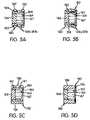
- FIGS. 5A-5Dillustrate cross-sectional side views of various embodiments of a seal structure according to the present invention
- FIG. 6Ais a longitudinal cross-sectional side view of a seal structure in accordance with another embodiment of the present invention, wherein the movable sealing plug is in a closed sealing position blocking the flow of the liquid injection solution;
- FIG. 6Bis a longitudinal cross sectional side view of seal structure similar to 6 A, but showing the movable sealing plug in an open by-pass position permitting the flow of the liquid injection solution;
- FIG. 6Cis a lateral cross sectional view of the seal structure of the present invention taken through the line 6 C- 6 C in FIG. 6A ;
- FIG. 6Dis a lateral cross sectional view of the seal structure of the present invention taken through the line 6 D- 6 D in FIG. 6B ;
- FIG. 7is a longitudinal cross-sectional view of a wet/dry automatic injector cartridge or chamber configuration in accordance with another embodiment of the present invention.
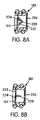
- FIGS. 8A and 8Bare longitudinal cross sectional views of two additional embodiments of seal structures in accordance with the present invention.
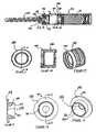
- FIG. 9is a longitudinal cross-sectional view of a chamber and needle assembly according to a further embodiment of the invention.
- FIG. 10is a perspective view of an outer sealing member in the chamber and needle assembly of FIG. 9 ;
- FIG. 11is a front elevational view of the outer sealing member of FIG. 10 ;
- FIG. 12is a longitudinal sectional view of the outer sealing member of FIG. 10 , taken through Line 12 - 12 of FIG. 11 ;
- FIG. 13is a perspective view of a tapered insert in the chamber and needle assembly of FIG. 9 ;
- FIG. 14is a front elevational view of the tapered insert of FIG. 13 ;
- FIG. 15is a longitudinal sectional view of the tapered insert in the chamber and needle assembly of FIG. 13 , taken through Line 15 - 15 of FIG. 14 ;
- FIG. 16is a longitudinal sectional view of a portion of the needle assembly of FIG. 9 , illustrating a chamber behind the needle assembly filter;
- FIGS. 17A-17Fare sectional and partially sectional views of a chamber illustrating a process for filling it with dry and liquid medicament components.
- the present inventionis described in connection with a push button type auto injector, whereby the user removes an end cap assembly and presses a button to trigger the injection process.
- the present inventionis not limited to push button type automatic injectors; rather, it is contemplated that the present invention may be incorporated into a nose activated auto injector, as described for example in U.S. Pat. No. 5,354,286, the disclosure of which is hereby incorporated herein by reference for such teaching.
- FIG. 1is a longitudinal cross-sectional view of an automatic injector assembly 10 in accordance with an embodiment of the present invention.
- the automatic injector assembly 10includes a generally hollow tubular plastic housing 110 .
- the housing 110includes an injection end 111 and an activation end 112 , as shown in FIG. 1 .
- an actuator assembly 120is inserted into the rearward end of the housing 110 .
- the actuator assembly 120is received within the housing 110 until flange 115 of a sleeve member 144 is captured within an annular groove 117 on the interior surface of housing 110 .
- a removable safety cap 130is releasably secured to the actuator assembly 120 .
- the actuator assembly 120may be of any conventional type as known in the art, such as that disclosed in commonly assigned U.S. Pat. No. 5,391,151 hereby incorporated by reference.
- the present inventionemploys a rear-end activating device, similar to that in the aforementioned U.S. Pat. No. 5,391,151, and is therefore only briefly described herein.
- the actuator assembly 120includes an activation button sleeve 132 having internal activation surfaces 134 .
- the activation assemblyfurther includes a plastic collet 122 with a split rearward portion forming spring fingers 136 as known in the art.
- the safety cap 130has a pin portion 138 that extends between the spring fingers 136 so as to keep them spread apart when the injector is in a storage condition.
- the spring fingers 136terminate in semi-conical configurations including rearwardly facing sloping surfaces 139 and forwardly facing flat surfaces 142 .
- the collet 122is surrounded by a cylindrical sleeve 144 having inwardly extending flange 146 at the rearward end thereof.
- the collet 122has a forward annular flange 148 .
- a coil spring 250surrounds the collet 122 and is compressed between the flange 148 and flange 146 .
- the collet flat surfaces 142are retained in engagement with the rearwardly facing surfaces of the flange 146 , and thus prevented from moving off of the flange surfaces by the pin 138 when the injector is stored.
- the safety pin 130is manually pulled off of the rear end of the injector, thus removing pin 138 from between the fingers 136 .
- the activation button 132can then be pushed inwardly, and as a result of the activation surfaces thereof, 134 engages the sloping surfaces 139 of the spring fingers 136 . This forces the spring fingers 136 inwards toward one another and off of the retaining surfaces of the flange 146 .
- the compressed spring 250is then free to release the stored energy therein to move the collet 122 forwardly under the force of the spring to affect an injection operation as will be described later in more detail.
- the actuator assembly 120may be of any type known in the automatic injector art that employs releasable stored energy. For example, rather than employing a spring, it may employ a charge of compressed gas.
- a vial or chamber 150Located within the interior of the housing 110 is a vial or chamber 150 , preferably made of glass, for containing both a liquid injection solution and a dry medicament, or other types of medicament portions, as appropriate.
- the chamber 150is preferably a hollow cylinder, with a smooth cylindrical inner surface.
- the liquid injection solutionis located within a wet portion or compartment 151 of the chamber 150 .
- the dry medicamentis located within a dry portion 152 or compartment of the chamber 150 . It is contemplated that the dry medicament may be in powder, lyophilized, freeze-dried, or any other solid formulation known in the art.
- a seal structure 160engages the interior side walls of the chamber 150 to seal the dry portion 152 from the wet portion 151 and to prevent seepage of the liquid injection solution into the dry portion 152 prior to activation of the injector assembly.
- a needle assembly 140mounts to the forward end of vial or chamber 150 to inject the medicament upon activation of the injector assembly.
- the forward end portion of the chamber 150has an annular groove 153 formed therein for attachment of the needle assembly 140 .
- the needle assembly 140includes a funnel-shaped needle support 143 .
- the wide end of the needle support 143has an annular rib 145 that is snap-fit into groove 153 to form a seal with the chamber 150 .
- the needle support 143can be made of a resilient plastic material, or metal with a rubber seal that seats into groove 153 .
- the forward narrow end 147 (see FIG. 2A ) of the needle support 143sealingly receives the rearward end of hollow needle 141 .
- the needle support 143forms a sealed fluid channel from the chamber 150 to the needle 141 .
- a rubber needle sheath 202surrounds the needle 141 and receives the narrow end 147 of the needle support 143 .
- a filter 190is sealingly retained across the entire wide-end mouth of the needle support 143 by an annular sealing washer 156 . Alternatively, the filter 190 could be ultrasonically welded or otherwise secured to the needle support 143 .
- FIGS. 2B , 3 A, and 4illustrate another embodiment of a needle assembly 140 and chamber 150 .
- the chamber 150 in this embodimentis known in the art as a dental cartridge.
- the dental cartridgehas a cylindrical rear portion and a narrowed forward neck portion defining an outer annular groove 153 .
- the forward end of the dental cartridgedefines an annular flange portion 154 .
- the needle support 143has a rearward annular flange 155 that receives an annular sealing member 156 that surrounds both sides of flange 155 .
- the sealing member 156serves to seal a filter 190 over the wide end of the funnel shaped needle support 143 .
- the rearward surface of the sealing member 156is sealingly clamped against the forward surface of chamber flange 154 by a metal retaining clamp 157 as best seen in FIG. 4 .
- forward end 1221 of the collet 122extends into the rearward end of chamber 150 and is adapted to connect with a plunger 170 rearwardly sealing the wet container 151 .
- the plunger 170is adapted to sealingly engage the side wall of the wet container 150 to prevent leakage of the contents (e.g., liquid injection solution) of the wet container 151 .
- the plunger 170is preferably formed from a material having low frictional properties such that the collet 122 and plunger 170 may easily slide within the wet container 150 when operated. Alternatively, the plunger 170 may be lubricated with silicone or other suitable non-reactive lubricant.
- the movement of the collet 122 and the plunger 170pressurizes the liquid located within the wet container 151 .
- a suitable medicamentis located within a dry container 152 .
- FIGS. 1 and 2Ais advantageous in that it has an open mouth configuration wherein the needle-end of the vial or chamber is not significantly narrowed or tapered.
- Such an open mouth configurationpermits direct access to the dry portion 152 of chamber 150 for easy loading. Further, the open mouth configuration aids in preventing cross contamination between wet portion 151 and dry portion 152 in that the dry portion 152 does not have to be filled through liquid portion 151 of chamber 150 .
- Needle assembly 140can be mounted to vial or chamber 150 in a snap-on configuration ( FIG. 3B ), an internal mount configuration ( FIG. 3C ), or an external needle assembly configuration ( FIG. 3D ).
- seal structure 160is adapted to engage the interior side walls of chamber 150 to prevent passage of the contents (e.g., liquid injection solution) of wet portion 151 into the dry portion 152 prior to activation of the automatic injection assembly.
- seal structure 160can include an outer sealing member 180 , a movable sealing plug 166 , a by-pass zone 165 , at least one flow path 167 , and preferably also includes a filter or membrane 164 .
- seal structure 160can preferably be formed as a six piece ( FIG. 5A ), five piece ( FIG. 5B ), four piece ( FIG. 5C ), or three piece ( FIG. 5D ) configuration.
- the outer sealing structure 180 of the six piece configurationcan comprise a two piece annular rigid body 181 wherein members 181 a , 181 b thereof are formed into the two piece rigid body using, e.g., annular weld connections or other bonding techniques known in the art.
- Outer sealing structure 180can further include multiple external sealing members 182 , e.g., two O-rings, to provide an annular sealing engagement with the inner wall of vial or compartment 150 .
- the sealing structure 180further includes an internal plug member 166 and a filter or dispersion membrane 164 as will be discussed in greater detail later.
- outer sealing structure 180can include a single external sealing member 182 , e.g., a unitary gasket, to provide an annular sealing engagement with the inner wall of vial or compartment 150 .
- External sealing member 182may optionally be secured to two piece rigid body 181 using any bonding techniques known in the art.
- rigid body members 181 a , 181 bmay be shaped such that they securingly engage external sealing members 182 within notched recesses 183 .
- sealing members 182may be secured to rigid body members 181 a , 181 b by an interference fit.
- a filter or membrane 164is clamped in place at the proximal end of flow path 167 between member 181 a and member 181 b of the two piece rigid body.
- outer sealing structure 180comprises a unitary internal rigid member 181 and an external sealing member 182 .
- internal rigid member 181 and external sealing member 182may optionally be secured together using any bonding techniques known in the art.
- internal rigid member 181 and external sealing member 182may be formed such that they securingly engage each other using a combination of notched recesses 183 and extending shoulders 184 .
- the filter or membrane 164can be held in place between internal rigid member 181 and shoulder 184 of external sealing member 182 .
- the filter 164may be ultrasonically welded or otherwise secured to the rigid member 181 .
- outer sealing object 180can comprise a unitary external sealing member 182 which can optionally be molded so as to accommodate filter or member 164 within retaining recess 185 .
- FIGS. 6A and 6Billustrate another embodiment that is very similar to that of FIG. 5A , but provides a slightly different shape for outer annular rigid body 181 and particularly the members 181 a , 181 b thereof.
- external sealing member 182is preferably formed from a non-reactive elastomer material which can provide for the necessary sealing engagement with the inner wall of vial or compartment 150 . Further, external sealing member 182 can optionally be lubricated with silicon or other suitable non-reaction lubricant to facilitate movement of the outer sealing object 180 forwardly within vial or compartment 150 upon receiving sufficient force as will be described.
- the movable sealing plug 166is preferably formed from a material, such as an elastomer or PTFE, having low frictional properties such that the sealing plug 166 may easily slide within outer sealing object 180 when the injector is activated.
- the movable sealing plug 166may also optionally be lubricated with silicon or other suitable non-reactive lubricant.
- the outer annular structure 180defines an inner surface having a smooth cylindrical configuration towards the rearward portion 169 thereof, and longitudinally extending grooves 168 towards the forward portion thereof.
- the grooves 168create a flowpath or flowpaths 167 through which liquid in the wet compartment 151 can bypass seal plug 166 when the plug 166 is moved forwardly from sealing engagement with cylindrical surface portion 169 into the grooved portion 168 .
- the movement of the sealing plug 166 into the by-pass area 165opens the fluid flow path 167 between wet portion 151 and dry portion 152 .
- the movable sealing plug 166preferably includes a plurality of circumferential grooves 186 to provide for enhanced sealing engagement and to facilitate sliding action of the plug 166 .
- the seal structure 160preferably includes filter or membrane 164 at the end of flow path 167 through which the liquid injection solution may pass after the injector has been activated.
- the liquid injection solutionthen enters the dry portion 152 of the chamber 150 where it mixes with and dissolves the dry medicament. More particularly, the filter 164 disperses the liquid injection solution exiting the seal structure 160 to present laminar fluid flow to the full surface of the dry medicament, thereby wetting the entire surface of the dry medicament for rapid and complete dissolution.
- the filter membrane 164can be any structure that generally uniformly distributes the liquid across the entire diameter of the chamber 150 for enhanced dissolution of the dry medicament.
- the plunger 170then begins to travel forwardly through the chamber 150 .
- the increased pressure within the wet compartment 151moves the sealing plug 166 from a first sealed position wherein sealing plug 166 is sealingly engaged with surface 169 of outer sealing structure 180 ( FIG. 6A ) to a second by-pass position ( FIG. 6B ) that allows the injection solution to flow through flow path 167 created by grooves 168 and thereby through seal structure 160 .
- the high pressure developed within the wet portion 151 in response to movement of the collet 122 and the plunger assembly 170forces the liquid injection solution through the seal structure 160 dissolving the drug into a medicament injection solution which will then be forced out through the needle 141 and into the patient.
- the plunger 170will eventually contact the seal structure 160 , which, in a preferred embodiment, causes the seal structure 160 to move in the direction of the needle assembly 140 . Movement of the seal structure 160 would cause any remaining solution within the portion 152 to be dispersed through the needle assembly 140 , so as to reduce the amount of residual medicament remaining within the chamber 150 .
- a membrane or filter 190is preferably provided adjacent the needle assembly 140 to prevent any dry medicament particles from clogging the rearward end of needle 141 prior to an injection operation.
- the membrane 190may also serve to slightly restrict or slow injection of medicament into the patient, to facilitate more thorough dissolution during injection.
- a medicament support 190is preferably provided between the end of the dry compartment 152 and the needle assembly 140 .
- the support 190can serve to prevent blockage of the needle assembly 141 by preventing the dry medicament from entering the area surrounding the needle assembly 140 while permitting passage of the mixture of dissolved medicament and liquid injection solution.
- the support 190may be configured as described in U.S. Provisional Application No. 60/238,448, which is herein incorporated by reference in a manner consistent with this disclosure. It is contemplated that multiple supports 190 may be located within the dry compartment 152 . The provision of the supports 190 may also improve the laminar flow of the liquid injection solution through the dry medicament thereby improving dissolution.
- a diaphragm assembly(not shown) may also be provided adjacent the medicament support 190 , as known in the art.
- the diaphragm assemblyacts to prevent the passage of the liquid injection solution to the needle assembly 140 prior to activation of the actuator assembly 120 . More particularly, the diaphragm assembly will not rupture until either the butt end of the needle assembly 140 ruptures the expanded diaphragm or sufficient pressure builds in the dry compartment 160 to rupture the diaphragm, again as known in the art.
- the movement of the collet 122causes the injection needle 141 of the injection assembly 140 to advance and protrude through the housing 110 .
- the injection of the medicamentcan be performed with a simple operation.
- the usersimply removes the end cap assembly 130 , locates the injection end of the housing 110 adjacent the injection site, and presses the push button 132 .
- This operationautomatically triggers the operation of the drive assembly or spring 250 to advance the collet 122 causing the liquid injection solution located within the wet portion 151 to enter the dry portion 152 through the seal structure 160 .
- the dissolved medicamentis then transmitted through the injection needle 141 to provide the user with the necessary dose of medicament.
- the automatic injector 10 in accordance with the present inventionreduces the amount of time required to administer medicament compared to other wet/dry injectors and eliminates the need for mixing by the user.
- the seal structure 160advantageously enables the manufacture of a superior wet/dry auto injector with a complementary combination of components that are either known in the art of conventional auto-injectors or are otherwise relatively simple to manufacture.
- the seal structure 160enables sufficient mixing of wet and dry medicament components without requiring manual shaking.
- This mixing actionis enhanced by the filter or membrane 164 .
- the filter 164is a supported, hydrophobic acrylic copolymer cast on a non-woven nylon support. Preferably, it is a FlouRepel treated membrane for superior oleophobicity/hydro-phobicity.
- the automatic injector cartridgein another embodiment, shown in FIG. 7 , includes a needle assembly 140 located within the dry portion 152 .
- the needle assembly 140extends within the dry portion 152 to the sealing structure 180 , described above in connection with FIGS. 5A-5D .
- the sealing structure 180separates the dry portion 152 from the wet portion 151 .
- the cartridgefurther includes a plunger 170 positioned therein.
- the plunger 170is configured to engage the collet 122 of the activation assembly 120 .
- the cartridgeincludes a sheath 301 .
- the sheath 301maintains the needle 141 in a sterile environment until it projects from the end of the sheath 301 in response to activation of the activation assembly 120 .
- the needle assembly 140passes through the dry portion 152 as the wet medicament passes through the sealing structure 180 .
- no inner plug 166is provided.
- the outer structure 180is simply complemented by a seal membrane 226 that extends across the inner area defined by the inner surface of the outer structure.
- pressurization of the wet compartment 151causes the seal membrane 226 to rupture, thereby allowing the seal structure 160 to permit liquid to pass therethrough.
- the member 232 on which the pointed member 228 is mountedhas a plurality of passages 234 that permits fluid to pass therethrough.
- Filter or membrane 164is preferably mounted distal to the passages 234 to present laminar or distributed flow to the dry medicament.
- An injector according to the present inventionwas loaded with liquid injection solution and dry medicament and activated with the follow results.
- a cover assemblydescribed for example in U.S. Pat. No. 5,295,965 (the disclosure of which is specifically incorporated herein by reference) may be secured to the injection end of the housing 110 after deployment of the medicament.
- the automatic injectormay further include a nipple plunger assembly, as described for example in U.S. Pat. No. 5,713,866 (the disclosure of which is specifically incorporated herein by reference).
- the forward dry chamber 152contains the needle 141 , as shown in FIG. 7 .
- the needle 141is forced through a forward plug stopper upon initial compression of the two chamber system.
- providing the needle 141 in the forward chamber 152provides improved longitudinal compactness of the design.
- a pre-filled syringeis provided with the seal structure disposed between wet and dry components.
- the seal structure 160can be used in the same type of injector described herein, except rather than employing a dry (powder) medicament separated by a liquid component, a first liquid medicament is separated from a second fluid component by the seal structure 160 .
- the seal structure 160can be used in what is known in the art as a “needleless injector” where an injection can be made into a patient without a needle or cannula.
- FIG. 9is a longitudinal cross-sectional view of a chamber 350 mounted to a needle assembly 340 according to a further embodiment of the invention. Neither a housing 110 nor an actuator assembly 120 is shown in FIG. 9 ; however, the chamber 350 and needle assembly 340 may be used with the housings 110 and actuator assemblies 120 described above or with substantially any known housing or actuator assembly.
- the chamber 350has a wet portion or compartment 151 and a dry portion or compartment 152 .
- a sealing structure 360separates the wet portion 151 and the dry portion 152 .
- the sealing structure 360includes an outer sealing member 380 , a moveable sealing plug 166 , a by-pass zone 165 , and may also include a filter or dispersion membrane 164 .
- a moveable sealing plug 166is shown in FIG. 9
- the sealing structure 360may include a rupturable seal membrane 226 instead of a sealing plug 166 , as shown in FIGS. 8A and 8B .
- FIG. 10is a perspective view of the outer sealing member 380 .
- FIG. 11is a front elevational view of the sealing member 380
- FIG. 12is a sectional view of the outer sealing member 380 taken through Line 12 - 12 of FIG. 11 .
- the outer sealing member 380has an annular wiper portion 382 that makes sealing contact with the inner wall of the dry portion 152 of the chamber 350 and extends axially forwardly, in the direction of actuating movement along the longitudinal axis of the chamber 350 , toward the needle assembly 140 .
- the wiper portion 382helps to eliminate the accumulation of powder around the sealing member 380 by “wiping” or “scraping” any accumulated powder away from the wall of the chamber 350 and directing it radially inwardly, where it can properly mix with the wet medicament portion as the sealing member 380 passes through the dry portion 152 .
- the wiper portion 382makes contact with the inner wall of the dry portion 152 of the chamber 350 along substantially the entirety of its length. The extent of contact between the wiper portion 382 and the inner wall of the dry portion 152 is possible, at least in part, because the wiper portion 382 extends axially.
- a wiper portion 382although shown in the embodiment of FIG. 9 , may be used in any of the embodiments shown and described above and in any variations thereof
- the chamber 350has an “open mouth” configuration; i.e., the container itself does not taper substantially as it meets the needle assembly 340 (for example, as compared with the embodiment shown in FIG. 3A ).
- the advantages of having an “open mouth” containerwere described above with respect to the container 150 . If the “mouth” of the container (i.e., the opening into the dry portion 152 of the container) is open and wide, it becomes easier to load the dry component of the medicament. However, having a tapered portion adjacent to the needle assembly 340 helps to direct the medicament radially inwardly, toward the needle assembly 340 , when the injection is taking place.
- the chamber 350includes a tapered insert 384 at its mouth, just behind the needle assembly 340 .
- FIG. 13is a perspective view of the tapered insert 384
- FIG. 14is a front elevational view
- FIG. 15is a sectional view through Line 15 - 15 of FIG. 14 .
- the tapered insert 384tapers radially inwardly as it extends axially forwardly, such that it forms a funnel portion 386 with a small central opening 388 at one end.
- the tapered insert 384also has a rearward open end 389 with a larger open diameter.
- the insert 384sealingly engages the walls of the chamber 350 .
- Extending radially outward from the outer surface of the funnel portion 386 proximate to the small central opening 388is an annular sealing flange 390 .
- the annular sealing flange 390is an integral portion of the tapered insert 384 .
- the annular sealing flange 390may be joined to the funnel portion 386 by adhesives or other securing methods. Additionally, as will be described in more detail below, in some configurations, the annular sealing flange 390 may be absent.
- the insert 384is preferably formed from a material that will not react with the dry medicament stored in the compartment 152 .
- the chamber 350 and needle assembly 340include a metallic skirt, generally indicated at 392 , that is rolled or crimped so as to capture or secure the needle assembly 340 to the front end of the chamber 350 .
- the annular sealing flange 390fits between the chamber 350 and needle assembly 340 so as to form a seal between them.
- the entire tapered insert 384may be made of an elastomeric or other rubber material suitable for sealing.
- the tapered insert 384may be removed from the chamber 350 in order to effect the loading of the dry medicament and then inserted into the chamber 350 prior to joining with the needle assembly 340 .
- the tapered insert 384is shown with a funnel portion 386 of constant, radially inward taper, the tapering of the tapered insert 384 may be of any type that will facilitate fluid flow from the chamber 350 into the needle assembly 340 .
- the small, central opening 388 in the insert 384is covered by a filter 190 that is positioned between the tapered insert 384 and the needle support 343 to filter fluids passing from the chamber 350 into the needle assembly 340 , so as to prevent any undissolved medicament from entering the needle assembly 340 .
- a filter 190Forward of the filter 190 , defined by the rearward (container-facing) side of the needle support 343 is a chamber 394 that tapers radially inwardly toward its forward end.
- the chamber 394is contoured to expose a substantial portion of the surface area of the filter 190 to the flow between the chamber 350 and the needle assembly 340 .
- the chamber 394has an opening at least as large as the small central opening 388 in the tapered insert 384 .
- the chamber 394is substantially hemispherical, although other configurations may be used.
- the chamber 394can be seen more clearly in FIG. 16 , which is a longitudinal cross-sectional view of a portion of the needle assembly 340 .
- the chamber 394allows greater, more laminar, and more fully developed flow through the filter 190 to the needle 141 .
- the chamber 394is shaped to direct the flow of medicament to the needle 141 .
- neither the needle 141 nor any other structureprotrudes into the chamber 394 .
- a chamber 394 and needle assemblysuch that a portion of the end of the needle protruded into the chamber 394 , such an arrangement might cause turbulent flow around the end of the needle that protruded into the chamber 394 , or might otherwise eliminate some of the benefits of the chamber 394 .
- the sealing member 380 with wiper portion 382 , tapered insert 384 , and chamber 394may all be used in a wet/wet autoinjector assembly that includes two fluid medicament components.
- a burstable membraneis typically positioned over the opening of the compartment adjacent to the needle assembly, in order to prevent fluid in that compartment from leaking out of the compartment and into the needle assembly.
- a burstable membranemay be provided as a portion of the tapered insert 384 .
- the burstable membranecould be positioned in the funnel portion 386 of the insert.
- the sealing member 380 , tapered insert 384 , and chamber 394may also be used in a wet/dry or wet/wet autoinjector assembly that does not include all of the features described above.
- the tapered insert 384 and chamber 394may be used in any wet/dry or wet/wet autoinjector in order to improve the loading and dispensing performance of the autoinjector.
- a chamber for an autoinjectormay be filled with appropriate medicament components in several different ways.
- one common way to fill an autoinjector chamberis to fill a first medicament (e.g., a wet medicament) through an opening in the chamber and then fill a second medicament (e.g., a dry medicament) through that same opening in the chamber.
- a first medicamente.g., a wet medicament
- a second medicamente.g., a dry medicament
- This processtends to cause cross-contamination because both wet and dry medicaments are filled through the same opening.
- any powder that accumulates around the openingmay mix with a subsequently-filled wet medicament, thereby contaminating the contents of the wet compartment.
- the wet medicamentis filled first, liquid that accumulates around the opening may mix with some of the subsequently-filled dry medicament, thereby contaminating the contents of the dry compartment.
- a chamber 150 , 350it is advantageous to fill the chamber 150 , 350 using a separate opening in the chamber 150 , 350 for each type of medicament, thus eliminating the cross-contamination problem.
- This sort of filling process for a chamber 150 , 350includes a number of tasks and will be described below with respect to the chamber 350 , although the described process is, in general, equally applicable to the other embodiments described above. Ordinarily, the filling process would be performed in an aseptic environment.
- the chamber 350is initially open at both ends and does not include any interior structures, as shown in FIG. 17A .
- a seal structuresuch as seal structure 360 , is first inserted into the chamber 350 so that it is positioned substantially as shown in FIG. 17B .
- the chamber 350is removed to or placed in a low particulate aseptic environment, and is positioned so that the wet portion or compartment 151 can be filled through an opening 396 in the rear end of the chamber 350 , as shown in FIG. 17C .
- the low particulate environmentprevents possible cross-contamination of the wet portion 151 .
- the opening 396 in the rear end of the chamber 350is sealed by installing the plunger 170 , as shown in FIG. 17D .
- the placement of the chamber 350 in a low particulate environment prior to filling the wet portion 151helps to prevent contamination of the wet portion 151 by powder or other particulates.
- the chamber 350is removed from the low particulate environment and is placed in an appropriate aseptic environment so that the dry portion or chamber 152 of the chamber 350 can be filled through an opening 398 in the front of the chamber 350 .
- One way to fill the dry portion 152is to place a dry powder directly into the dry portion 152 through the opening 398 , as shown in FIG. 17E .
- Another way to fill the dry portion 152is to fill the dry portion 152 with a liquid medicament through the opening 398 and then lyophilize the liquid medicament directly in the dry portion 152 to leave only the desired dry medicament. While this process of liquid filling and lyophilizing may be used, it sometimes leaves residues in the dry portion 152 , which may interfere with the stability of the dry medicament or otherwise contaminate it.
- a third way to fill the dry portion 152is to lyophilize a liquid medicament in a separate container to form a lyophilized dry medicament tablet 400 and then deposit the dry medicament tablet 400 in the dry portion 152 through the opening 398 , as shown in FIG. 17F .
- This variation of the filling processis used most advantageously with a chamber that has a relatively wide opening into its dry portion, so that tablets of various sizes can be accommodated. If a chamber has a relatively narrow opening into its dry portion, it may be necessary to fill that dry portion with powder, or to lyophilize a liquid medicament directly in the dry portion to form a dry powder.
- a tapered insert 384is placed in opening 398 of the chamber 350 and the needle assembly 340 is secured over the tapered insert 384 .
- the chamber 350is as shown in FIG. 9 .
Landscapes
- Health & Medical Sciences (AREA)
- Vascular Medicine (AREA)
- Engineering & Computer Science (AREA)
- Anesthesiology (AREA)
- Biomedical Technology (AREA)
- Heart & Thoracic Surgery (AREA)
- Hematology (AREA)
- Life Sciences & Earth Sciences (AREA)
- Animal Behavior & Ethology (AREA)
- General Health & Medical Sciences (AREA)
- Public Health (AREA)
- Veterinary Medicine (AREA)
- Infusion, Injection, And Reservoir Apparatuses (AREA)
- Medical Preparation Storing Or Oral Administration Devices (AREA)
- Feeding, Discharge, Calcimining, Fusing, And Gas-Generation Devices (AREA)
- Organic Low-Molecular-Weight Compounds And Preparation Thereof (AREA)
Abstract
Description
| Loaded | Dispensed | Operational | |||
| Dry Powder | Fluid | Dry Powder | Fluid | Time |
| Mg | Ml | % | mg | ml | Secs. | ||
| 531 | 2.7 | 94 | 497 | 2.3 | 4.0 | ||
| 557 | 2.7 | 93 | 515 | 2.3 | 4.5 | ||
| 582 | 2.6 | 92 | 537 | 2.2 | 4.4 | ||
Claims (20)
Priority Applications (1)
| Application Number | Priority Date | Filing Date | Title |
|---|---|---|---|
| US11/698,964US7608055B2 (en) | 2000-10-10 | 2007-01-26 | Flow-path inserts for wet/dry automatic injectors |
Applications Claiming Priority (7)
| Application Number | Priority Date | Filing Date | Title |
|---|---|---|---|
| US23845800P | 2000-10-10 | 2000-10-10 | |
| US23844800P | 2000-10-10 | 2000-10-10 | |
| US23844700P | 2000-10-10 | 2000-10-10 | |
| US09/897,422US6641561B1 (en) | 2000-10-10 | 2001-07-03 | Drug delivery device |
| US09/972,202US6770052B2 (en) | 2000-10-10 | 2001-10-09 | Wet/dry automatic injector assembly |
| US10/690,987US7621887B2 (en) | 2000-10-10 | 2003-10-23 | Wet/dry automatic injector assembly |
| US11/698,964US7608055B2 (en) | 2000-10-10 | 2007-01-26 | Flow-path inserts for wet/dry automatic injectors |
Related Parent Applications (1)
| Application Number | Title | Priority Date | Filing Date |
|---|---|---|---|
| US10/690,987DivisionUS7621887B2 (en) | 2000-10-10 | 2003-10-23 | Wet/dry automatic injector assembly |
Publications (2)
| Publication Number | Publication Date |
|---|---|
| US20070142768A1 US20070142768A1 (en) | 2007-06-21 |
| US7608055B2true US7608055B2 (en) | 2009-10-27 |
Family
ID=34549868
Family Applications (11)
| Application Number | Title | Priority Date | Filing Date |
|---|---|---|---|
| US10/690,987Expired - LifetimeUS7621887B2 (en) | 2000-10-10 | 2003-10-23 | Wet/dry automatic injector assembly |
| US11/698,937Expired - LifetimeUS8568367B2 (en) | 2000-10-10 | 2007-01-26 | Needle assemblies for wet/dry automatic injectors |
| US11/698,964Expired - LifetimeUS7608055B2 (en) | 2000-10-10 | 2007-01-26 | Flow-path inserts for wet/dry automatic injectors |
| US11/698,965Expired - Fee RelatedUS7749190B2 (en) | 2000-10-10 | 2007-01-26 | Seal structures for wet/dry automatic injectors |
| US12/784,595Expired - Fee RelatedUS8187220B2 (en) | 2000-10-10 | 2010-05-21 | Seal structures for wet/dry automatic injectors |
| US13/468,421Expired - Fee RelatedUS8506526B2 (en) | 2000-10-10 | 2012-05-10 | Seal structures for wet/dry automatic injectors |
| US13/939,647AbandonedUS20150018761A1 (en) | 2000-10-10 | 2013-07-11 | Seal Structures for Wet/Dry Automatic Injectors |
| US14/743,905AbandonedUS20150283327A1 (en) | 2000-10-10 | 2015-06-18 | Seal Structures for Wet/Dry Automatic Injectors |
| US15/147,046AbandonedUS20160250419A1 (en) | 2000-10-10 | 2016-05-05 | Seal Structures for Wet/Dry Automatic Injectors |
| US15/822,441AbandonedUS20180256824A1 (en) | 2000-10-10 | 2017-11-27 | Seal Structures for Wet/Dry Automatic Injectors |
| US16/673,300AbandonedUS20200069884A1 (en) | 2000-10-10 | 2019-11-04 | Seal Structures for Wet/Dry Automatic Injectors |
Family Applications Before (2)
| Application Number | Title | Priority Date | Filing Date |
|---|---|---|---|
| US10/690,987Expired - LifetimeUS7621887B2 (en) | 2000-10-10 | 2003-10-23 | Wet/dry automatic injector assembly |
| US11/698,937Expired - LifetimeUS8568367B2 (en) | 2000-10-10 | 2007-01-26 | Needle assemblies for wet/dry automatic injectors |
Family Applications After (8)
| Application Number | Title | Priority Date | Filing Date |
|---|---|---|---|
| US11/698,965Expired - Fee RelatedUS7749190B2 (en) | 2000-10-10 | 2007-01-26 | Seal structures for wet/dry automatic injectors |
| US12/784,595Expired - Fee RelatedUS8187220B2 (en) | 2000-10-10 | 2010-05-21 | Seal structures for wet/dry automatic injectors |
| US13/468,421Expired - Fee RelatedUS8506526B2 (en) | 2000-10-10 | 2012-05-10 | Seal structures for wet/dry automatic injectors |
| US13/939,647AbandonedUS20150018761A1 (en) | 2000-10-10 | 2013-07-11 | Seal Structures for Wet/Dry Automatic Injectors |
| US14/743,905AbandonedUS20150283327A1 (en) | 2000-10-10 | 2015-06-18 | Seal Structures for Wet/Dry Automatic Injectors |
| US15/147,046AbandonedUS20160250419A1 (en) | 2000-10-10 | 2016-05-05 | Seal Structures for Wet/Dry Automatic Injectors |
| US15/822,441AbandonedUS20180256824A1 (en) | 2000-10-10 | 2017-11-27 | Seal Structures for Wet/Dry Automatic Injectors |
| US16/673,300AbandonedUS20200069884A1 (en) | 2000-10-10 | 2019-11-04 | Seal Structures for Wet/Dry Automatic Injectors |
Country Status (18)
| Country | Link |
|---|---|
| US (11) | US7621887B2 (en) |
| EP (3) | EP1687047B1 (en) |
| JP (3) | JP4896727B2 (en) |
| KR (1) | KR101114630B1 (en) |
| CN (1) | CN100574822C (en) |
| AU (4) | AU2004285456B2 (en) |
| CA (2) | CA2542204C (en) |
| CY (2) | CY1113410T1 (en) |
| DK (3) | DK2308530T3 (en) |
| ES (3) | ES2389842T3 (en) |
| HU (1) | HUE029216T2 (en) |
| IL (4) | IL175073A (en) |
| NO (1) | NO20062215L (en) |
| PL (3) | PL1687047T3 (en) |
| PT (2) | PT2308529E (en) |
| SI (3) | SI1687047T1 (en) |
| TW (1) | TWI341214B (en) |
| WO (1) | WO2005042067A2 (en) |
Cited By (15)
| Publication number | Priority date | Publication date | Assignee | Title |
|---|---|---|---|---|
| US20070123818A1 (en)* | 2000-10-10 | 2007-05-31 | Meridian Medical Technologies, Inc. | Needle assemblies for wet/dry automatic injectors |
| US20140058442A1 (en)* | 2012-08-24 | 2014-02-27 | St. Jude Medical Puerto Rico Llc | Sealant storage, preparation, and delivery systems and related methods |
| US20150283324A1 (en)* | 2012-11-14 | 2015-10-08 | Ams Research Corporation | Cell delivery device and system with anti-clumping feature and methods for pelvic tissue treatment |
| US9907910B2 (en) | 2013-03-15 | 2018-03-06 | Windgap Medical, Inc. | Portable drug mixing and delivery device and associated methods |
| US9907911B2 (en) | 2014-08-18 | 2018-03-06 | Windgap Medical, Inc. | Portable drug mixing and delivery device and associated methods |
| US9987428B2 (en) | 2011-10-14 | 2018-06-05 | Amgen Inc. | Injector and method of assembly |
| US10195361B2 (en) | 2013-03-15 | 2019-02-05 | Windgap Medical, Inc. | Portable drug mixing and delivery system and method |
| US10220147B2 (en) | 2015-08-13 | 2019-03-05 | Windgap Medical, Inc. | Mixing and injection device with sterility features |
| US10569017B2 (en) | 2013-03-15 | 2020-02-25 | Windgap Medical, Inc. | Portable drug mixing and delivery device and associated methods |
| US10850037B2 (en) | 2013-03-22 | 2020-12-01 | Amgen Inc. | Injector and method of assembly |
| US11097055B2 (en) | 2013-10-24 | 2021-08-24 | Amgen Inc. | Injector and method of assembly |
| US11116903B2 (en) | 2014-08-18 | 2021-09-14 | Windgap Medical, Inc | Compression seal for use with a liquid component storage vial of an auto-injector |
| US11246842B2 (en) | 2014-12-18 | 2022-02-15 | Windgap Medical, Inc. | Method and compositions for dissolving or solubilizing therapeutic agents |
| US12239823B2 (en) | 2013-12-18 | 2025-03-04 | Windgap Medical, Inc. | Drug mixing and delivery system and method |
| US12239822B2 (en) | 2013-03-15 | 2025-03-04 | Windgap Medical, Inc. | Portable drug mixing and delivery device and associated methods |
Families Citing this family (129)
| Publication number | Priority date | Publication date | Assignee | Title |
|---|---|---|---|---|
| US7544188B2 (en)* | 2001-07-19 | 2009-06-09 | Intelliject, Inc. | Medical injector |
| WO2003068290A2 (en) | 2002-02-11 | 2003-08-21 | Antares Pharma, Inc. | Intradermal injector |
| TWI252116B (en)* | 2003-07-21 | 2006-04-01 | Ping-De Huang | Safety syringe |
| EP2962660A1 (en) | 2004-02-02 | 2016-01-06 | Bimeda Research & Development Limited | Device for treating a teat canal of an animal |
| WO2006057636A1 (en) | 2004-11-22 | 2006-06-01 | Intelliject, Llc | Devices, systems, and methods for medicament delivery |
| US7648482B2 (en) | 2004-11-22 | 2010-01-19 | Intelliject, Inc. | Devices, systems, and methods for medicament delivery |
| US10737028B2 (en) | 2004-11-22 | 2020-08-11 | Kaleo, Inc. | Devices, systems and methods for medicament delivery |
| US7648483B2 (en) | 2004-11-22 | 2010-01-19 | Intelliject, Inc. | Devices, systems and methods for medicament delivery |
| US7947017B2 (en) | 2004-11-22 | 2011-05-24 | Intelliject, Inc. | Devices, systems and methods for medicament delivery |
| US11590286B2 (en) | 2004-11-22 | 2023-02-28 | Kaleo, Inc. | Devices, systems and methods for medicament delivery |
| HUE042286T2 (en) | 2005-01-24 | 2019-06-28 | Antares Pharma Inc | Needle-filled pre-filled syringe |
| US7731686B2 (en) | 2005-02-01 | 2010-06-08 | Intelliject, Inc. | Devices, systems and methods for medicament delivery |
| US8361026B2 (en) | 2005-02-01 | 2013-01-29 | Intelliject, Inc. | Apparatus and methods for self-administration of vaccines and other medicaments |
| US8231573B2 (en) | 2005-02-01 | 2012-07-31 | Intelliject, Inc. | Medicament delivery device having an electronic circuit system |
| US8206360B2 (en) | 2005-02-01 | 2012-06-26 | Intelliject, Inc. | Devices, systems and methods for medicament delivery |
| AU2006210865B2 (en) | 2005-02-01 | 2008-12-04 | Kaleo, Inc. | Devices, systems, and methods for medicament delivery |
| US9022980B2 (en) | 2005-02-01 | 2015-05-05 | Kaleo, Inc. | Medical injector simulation device |
| US20070060887A1 (en)* | 2005-08-22 | 2007-03-15 | Marsh David A | Ophthalmic injector |
| JP4834389B2 (en)* | 2005-11-29 | 2011-12-14 | 前田産業株式会社 | Injection device |
| WO2007131013A1 (en) | 2006-05-03 | 2007-11-15 | Antares Pharma, Inc. | Two-stage reconstituting injector |
| WO2007131025A1 (en) | 2006-05-03 | 2007-11-15 | Antares Pharma, Inc. | Injector with adjustable dosing |
| US7811252B2 (en)* | 2006-05-17 | 2010-10-12 | Alcon Research, Ltd. | Dosage control device |
| US7887521B2 (en)* | 2006-05-17 | 2011-02-15 | Alcon Research, Ltd. | Ophthalmic injection system |
| US7815603B2 (en)* | 2006-05-17 | 2010-10-19 | Alcon Research, Ltd. | Ophthalmic injection method |
| CA2662052C (en)* | 2006-08-31 | 2015-11-03 | Meridian Medical Technologies, Inc. | Vortex feature for drug delivery system |
| DE102006045959B3 (en)* | 2006-09-27 | 2008-01-10 | Lts Lohmann Therapie-Systeme Ag | Cylinder piston unit, e.g. for drug syringes with rubber pistons, has a cylinder and a piston guided in the cylinder and sealed with rubber in a sterile manner |
| US9022970B2 (en)* | 2006-10-16 | 2015-05-05 | Alcon Research, Ltd. | Ophthalmic injection device including dosage control device |
| JP2010506673A (en)* | 2006-10-16 | 2010-03-04 | アルコン リサーチ, リミテッド | Universal rechargeable limited reuse assembly for ophthalmic handpieces |
| CA2664160A1 (en)* | 2006-10-16 | 2008-09-12 | Alcon Research, Ltd. | Method of operating ophthalmic hand piece with disposable end |
| US20080281292A1 (en)* | 2006-10-16 | 2008-11-13 | Hickingbotham Dyson W | Retractable Injection Port |
| EP2125075A2 (en) | 2007-01-22 | 2009-12-02 | Intelliject, Inc. | Medical injector with compliance tracking and monitoring |
| WO2008098860A1 (en)* | 2007-02-14 | 2008-08-21 | Shl Medical Ab | Container for a medical device |
| US9566384B2 (en) | 2008-02-20 | 2017-02-14 | Unomedical A/S | Insertion device with horizontally moving part |
| EP3636301A1 (en) | 2008-03-10 | 2020-04-15 | Antares Pharma, Inc. | Injector safety device |
| USD994111S1 (en) | 2008-05-12 | 2023-08-01 | Kaleo, Inc. | Medicament delivery device cover |
| DK2280751T3 (en) | 2008-05-14 | 2022-02-28 | Biolyph Llc | REAGENT MIXTURE AND DELIVERY DEVICES AND METHODS THEREOF |
| WO2009148969A1 (en) | 2008-06-02 | 2009-12-10 | Sta-Med, Llc | Needle cover assembly for a syringe |
| DE102008030268B3 (en)* | 2008-06-19 | 2010-02-04 | Arzneimittel Gmbh Apotheker Vetter & Co. Ravensburg | Method for filling dual-chamber systems in pre-sterilizable carrier systems and pre-sterilisable carrier system |
| US8376993B2 (en) | 2008-08-05 | 2013-02-19 | Antares Pharma, Inc. | Multiple dosage injector |
| US8500682B2 (en) | 2008-09-18 | 2013-08-06 | Becton, Dickinson And Company | Medical injector with post-autoreconstitution dose setting and autoplunger drive |
| WO2010033806A2 (en) | 2008-09-18 | 2010-03-25 | Becton, Dickinson And Company | Needle mounting feature for ensuring proper reconstitution sequence |
| CN102186447B (en)* | 2008-10-15 | 2013-06-19 | 诺沃—诺迪斯克保健股份有限公司 | System for reconstitution of powdered drug |
| DE102009013211B4 (en) | 2009-03-17 | 2012-04-19 | Aap Biomaterials Gmbh | Bone cement vacuum mixing device and method for mixing bone cement |
| JP5732039B2 (en) | 2009-03-20 | 2015-06-10 | アンタレス・ファーマ・インコーポレーテッド | Hazardous drug injection system |
| AU2010242861A1 (en)* | 2009-04-30 | 2011-10-13 | Hyperbranch Medical Technology, Inc. | Applicator system for the delivery of surgical sealants |
| US8372036B2 (en) | 2009-05-06 | 2013-02-12 | Alcon Research, Ltd. | Multi-layer heat assembly for a drug delivery device |
| JP2013501568A (en)* | 2009-08-12 | 2013-01-17 | コーニンクレッカ フィリップス エレクトロニクス エヌ ヴィ | Pharmaceutical storage tank for drug delivery device |
| US10350364B2 (en) | 2009-11-11 | 2019-07-16 | Windgap Medical, Inc. | Portable Drug Mixing and Delivery Device and Associated Methods |
| US8177747B2 (en) | 2009-12-22 | 2012-05-15 | Alcon Research, Ltd. | Method and apparatus for drug delivery |
| US8302776B2 (en)* | 2009-12-30 | 2012-11-06 | Kimberly-Clark Worldwide, Inc. | Pack of oral care items |
| US8162882B2 (en) | 2010-06-23 | 2012-04-24 | Sta-Med, Llc | Automatic-locking safety needle covers and methods of use and manufacture |
| AU2011276396B2 (en) | 2010-06-29 | 2014-05-08 | Biolyph, Llc | Reagent preparation assembly |
| EP2595675B1 (en)* | 2010-07-22 | 2017-09-13 | Becton, Dickinson and Company | Needle assembly for mixing of substances |
| JP5843870B2 (en)* | 2010-10-01 | 2016-01-13 | サノフィ−アベンティス・ドイチュラント・ゲゼルシャフト・ミット・ベシュレンクテル・ハフツング | Needle assembly with release mechanism |
| DK3147032T3 (en) | 2010-11-18 | 2024-09-16 | Biolyph Llc | DEVICE FOR REAGENT MANUFACTURE AND DISTRIBUTION |
| JP2014503307A (en)* | 2010-12-30 | 2014-02-13 | メリディアン メディカル テクノロジーズ インコーポレイテッド | Automatic syringe with three chambers |
| HRP20211295T1 (en) | 2011-01-24 | 2021-11-12 | Otsuka Pharmaceutical Co., Ltd. | MEDICAL DEVICE CONTAINING CAKE PREPARATION CONTAINING ARIPIPRAZOLE AS ACTIVE INGREDIENT, AND CAKE PREPARATION CONTAINING ARIPIPRAZOLE AS ACTIVE INGREDIENT |
| US8939943B2 (en) | 2011-01-26 | 2015-01-27 | Kaleo, Inc. | Medicament delivery device for administration of opioid antagonists including formulations for naloxone |
| US9173999B2 (en) | 2011-01-26 | 2015-11-03 | Kaleo, Inc. | Devices and methods for delivering medicaments from a multi-chamber container |
| US8627816B2 (en) | 2011-02-28 | 2014-01-14 | Intelliject, Inc. | Medicament delivery device for administration of opioid antagonists including formulations for naloxone |
| EP2495001A1 (en)* | 2011-03-03 | 2012-09-05 | Debiotech S.A. | Cannula inserter |
| WO2012166746A1 (en) | 2011-05-31 | 2012-12-06 | Sta-Med, Llc | Blood collection safety devices and methods of use and manufacture |
| DK2723426T3 (en) | 2011-06-21 | 2019-11-04 | Brent Buchine | AUTOMATIC MIXING AND DELIVERY SYSTEM |
| CA2745320A1 (en)* | 2011-07-06 | 2013-01-06 | Duoject Medical Systems Inc. | Reconstitution device |
| US9220660B2 (en) | 2011-07-15 | 2015-12-29 | Antares Pharma, Inc. | Liquid-transfer adapter beveled spike |
| US8496619B2 (en) | 2011-07-15 | 2013-07-30 | Antares Pharma, Inc. | Injection device with cammed ram assembly |
| DE102011112516B4 (en) | 2011-09-07 | 2024-02-29 | Stryker European Operations Holdings Llc | Container with a container for holding a liquid and a liquid removal device |
| US9486583B2 (en) | 2012-03-06 | 2016-11-08 | Antares Pharma, Inc. | Prefilled syringe with breakaway force feature |
| US9463280B2 (en)* | 2012-03-26 | 2016-10-11 | Medimop Medical Projects Ltd. | Motion activated septum puncturing drug delivery device |
| EP4186545A1 (en) | 2012-04-06 | 2023-05-31 | Antares Pharma, Inc. | Needle assisted jet injection administration of testosterone compositions |
| US9364610B2 (en) | 2012-05-07 | 2016-06-14 | Antares Pharma, Inc. | Injection device with cammed ram assembly |
| US9522235B2 (en) | 2012-05-22 | 2016-12-20 | Kaleo, Inc. | Devices and methods for delivering medicaments from a multi-chamber container |
| CN108420598B (en) | 2012-06-12 | 2021-03-09 | 爱尔康公司 | Hand-held gas mixer and injector assembly, hand-held gas injector device and method of mixing gas |
| WO2014093926A1 (en)* | 2012-12-14 | 2014-06-19 | Larson Bryan | Dual medicament carpule for dental syringes |
| GB2526948A (en) | 2012-12-27 | 2015-12-09 | Kaleo Inc | Systems for locating and interacting with medicament delivery devices |
| FI3659647T3 (en) | 2013-02-11 | 2024-03-28 | Antares Pharma Inc | NEEDLE-ASSISTED SPRAY INJECTOR WITH REDUCED TRIGGER FORCE |
| CA2905031C (en) | 2013-03-11 | 2018-01-23 | Hans PFLAUMER | Dosage injector with pinion system |
| WO2014165136A1 (en) | 2013-03-12 | 2014-10-09 | Antares Pharma, Inc. | Constant volume prefilled syringes and kits thereof |
| US10391262B2 (en) | 2014-03-18 | 2019-08-27 | Windgap Medical, Inc. | Removable actuating cap for use with an auto-injector assembly |
| WO2014145959A1 (en)* | 2013-03-15 | 2014-09-18 | Windgap Medical, Inc. | Portable detachable drug mixing and delivery system and method |
| WO2014186800A1 (en)* | 2013-05-17 | 2014-11-20 | Carrtech Llc | Filtering needle cap |
| US9707319B2 (en)* | 2013-06-20 | 2017-07-18 | Nordson Corporation | Device and method for improving hydration of a biomaterial |
| DK3021917T3 (en)* | 2013-07-16 | 2018-05-22 | Unl Holdings Llc | SPRAYES FOR PRE-MIXED AND MIXED WITH USE AND PHARMACEUTICAL PREPARATION |
| ITRM20130457A1 (en)* | 2013-08-05 | 2015-02-06 | Orofino Pharmaceuticals Group Srl | INTERMEDIATE PRODUCT FOR THE PREPARING OF SYRINGES OR CARTRIDGES WITH DOUBLE CHAMBER AND PRODUCTION PROCEDURE OF SUCH INTERMEDIATE PRODUCT |
| US20150059857A1 (en)* | 2013-08-27 | 2015-03-05 | Restek Corporation | Multichambered vial and method of mixing analytical reference materials |
| AR098613A1 (en) | 2013-12-06 | 2016-06-01 | Genentech Inc | APPLIANCES AND METHODS FOR THE ADMINISTRATION OF MEDICINES IN LOW VOLUMES |
| US10881796B2 (en)* | 2014-03-12 | 2021-01-05 | Min Wei | Automatic medication injection device |
| US10258583B2 (en) | 2014-05-01 | 2019-04-16 | Sun Pharmaceutical Industries Limited | Extended release liquid compositions of guanfacine |
| US20180104197A9 (en) | 2014-05-01 | 2018-04-19 | Sun Pharmaceutical Industries Limited | Extended release liquid compositions of metformin |
| US9962336B2 (en) | 2014-05-01 | 2018-05-08 | Sun Pharmaceutical Industries Limited | Extended release suspension compositions |
| JP2017514903A (en) | 2014-05-01 | 2017-06-08 | サン ファーマシューティカル インダストリーズ リミテッドSun Pharmaceutical Industries Ltd. | Sustained release suspension composition |
| US9517307B2 (en) | 2014-07-18 | 2016-12-13 | Kaleo, Inc. | Devices and methods for delivering opioid antagonists including formulations for naloxone |
| MX2017001332A (en)* | 2014-07-30 | 2017-08-02 | Sun Pharmaceutical Ind Ltd | Dual-chamber pack. |
| BR112017011464A2 (en) | 2014-12-08 | 2018-02-27 | Genentech, Inc. | drug delivery devices and methods of manufacturing a device |
| JP6720189B2 (en)* | 2015-01-08 | 2020-07-08 | ノボ・ノルデイスク・エー/エス | Needle unit with lockable needle shield and injection device with such needle unit |
| US10695495B2 (en) | 2015-03-24 | 2020-06-30 | Kaleo, Inc. | Devices and methods for delivering a lyophilized medicament |
| CA2990950A1 (en) | 2015-06-30 | 2017-01-05 | Kaleo, Inc. | Auto-injectors for administration of a medicament within a prefilled syringe |
| CZ2015822A3 (en)* | 2015-11-20 | 2017-03-08 | ChemProtect.SK s.r.o. | An autoinjector |
| US20170189272A1 (en)* | 2015-12-30 | 2017-07-06 | Unither Pharmaceuticals | Device for delivering a soluble product with a straw, in particular for children and/or the elderly, adapted cartridge |
| US20170231816A1 (en)* | 2016-02-16 | 2017-08-17 | Edwin Ryan | Ophthalmic injection device and method |
| JP6923552B2 (en) | 2016-04-08 | 2021-08-18 | マジック リープ, インコーポレイテッドMagic Leap,Inc. | Augmented reality systems and methods with varifocal lens elements |
| WO2017191485A1 (en)* | 2016-05-02 | 2017-11-09 | Sun Pharmaceutical Industries Limited | Dual-chamber pack for pharmaceutical compositions |
| US10369078B2 (en) | 2016-05-02 | 2019-08-06 | Sun Pharmaceutical Industries Limited | Dual-chamber pack for pharmaceutical compositions |
| US10238803B2 (en) | 2016-05-02 | 2019-03-26 | Sun Pharmaceutical Industries Limited | Drug delivery device for pharmaceutical compositions |
| KR101785902B1 (en)* | 2016-08-01 | 2017-10-17 | (주)이화바이오메딕스 | Apparatus for injecting liquid medicine which is capable of injecting additional fluid after completing first injection |
| US10926038B2 (en)* | 2016-11-01 | 2021-02-23 | Credence Medsystems, Inc. | System and method for safety syringe |
| WO2018119218A1 (en) | 2016-12-23 | 2018-06-28 | Kaleo, Inc. | Medicament delivery device and methods for delivering drugs to infants and children |
| CA3046354A1 (en) | 2017-01-17 | 2018-07-26 | Kaleo, Inc. | Medicament delivery devices with wireless connectivity and event detection |
| KR101811846B1 (en)* | 2017-03-15 | 2017-12-22 | 김휘화 | Safety improved semi-automatic syringe |
| US10773030B2 (en)* | 2017-07-28 | 2020-09-15 | C&M Tech Co., Ltd. | Safety syringe |
| US11679177B2 (en)* | 2017-08-08 | 2023-06-20 | Baxter International Inc. | Polymeric compositions, delivery devices, and methods |
| JP7173447B2 (en)* | 2017-11-03 | 2022-11-16 | バクスター・インターナショナル・インコーポレイテッド | Polymer composition, delivery device and method |
| KR102708626B1 (en)* | 2018-06-20 | 2024-09-20 | 코스카 패밀리 리미티드 | Systems and methods for delivering dual component drug formulations |
| US11929160B2 (en) | 2018-07-16 | 2024-03-12 | Kaleo, Inc. | Medicament delivery devices with wireless connectivity and compliance detection |
| US11224537B2 (en) | 2018-10-19 | 2022-01-18 | Alcon Inc. | Intraocular gas injector |
| US11357412B2 (en) | 2018-11-20 | 2022-06-14 | 42 Health Sensor Holdings Ltd. | Wearable cardiovascular monitoring device |
| US20220080124A1 (en)* | 2018-12-28 | 2022-03-17 | Novo Nordisk A/S | Drug reservoir for separate storage of substances |
| US11541179B2 (en) | 2019-02-22 | 2023-01-03 | Credence Medsystems, Inc. | System and method for safety syringe |
| CA3145580A1 (en) | 2019-08-09 | 2021-02-18 | Kaleo, Inc. | Devices and methods for delivery of substances within a prefilled syringe |
| US12268847B1 (en) | 2021-02-10 | 2025-04-08 | Kaleo, Inc. | Devices and methods for delivery of substances within a medicament container |
| BR112023022487A2 (en)* | 2021-04-30 | 2024-02-27 | Chugai Pharmaceutical Co Ltd | SYRINGE |
| JP1703753S (en) | 2021-05-18 | 2025-01-07 | Syringe | |
| JP1703751S (en) | 2021-05-18 | 2025-01-07 | Syringe | |
| JP1703752S (en) | 2021-05-18 | 2025-01-07 | Syringe | |
| JP1703754S (en) | 2021-05-18 | 2025-01-07 | Syringe | |
| USD995768S1 (en) | 2021-11-18 | 2023-08-15 | Chugai Seiyaku Kabushiki Kaisha | Syringe barrel |
| KR20250005335A (en) | 2022-04-26 | 2025-01-09 | 추가이 세이야쿠 가부시키가이샤 | Syringe with built-in filter containing pharmaceutical preparation |
| AU2022479894A1 (en)* | 2022-10-01 | 2025-05-01 | CARRTECH Corp. | Filtering needle assembly with seal plug |
| AU2024222228A1 (en)* | 2023-02-15 | 2025-07-31 | Genentech, Inc. | Pre-filled syringe with embedded filter |
Citations (80)
| Publication number | Priority date | Publication date | Assignee | Title |
|---|---|---|---|---|
| US2098524A (en)* | 1935-04-03 | 1937-11-09 | Arthur E Smith | Syringe |
| CH446620A (en) | 1967-01-31 | 1967-11-15 | Penicillin Ges Dauelsberg & Co | Multi-chamber injection syringe |
| DE1961166A1 (en) | 1968-12-27 | 1970-07-09 | Roussel Uclaf | Device for substances to be mixed at the point of use |
| US3592245A (en) | 1968-09-24 | 1971-07-13 | American Home Prod | Universal dispensing device for intravenous medications |
| US3736932A (en) | 1972-02-15 | 1973-06-05 | Sherwood Medical Ind Inc | Injection apparatus with filter |
| US3757779A (en)* | 1971-05-24 | 1973-09-11 | Century Labor Inc | Filter syringe |
| US3863624A (en) | 1973-06-15 | 1975-02-04 | Hans Gram | Vacuum curettage device |
| US3938513A (en) | 1974-01-03 | 1976-02-17 | Hargest Thomas S | Syringe filter and valve combination |
| US4043335A (en) | 1975-08-23 | 1977-08-23 | Soji Ishikawa | Needle holder device of medical administrating injector |
| US4060082A (en) | 1976-08-16 | 1977-11-29 | Mpl, Inc. | Dual-ingredient medication dispenser |
| US4215701A (en) | 1978-08-21 | 1980-08-05 | Concord Laboratories, Inc. | Elastomeric plunger tip for a syringe |
| US4266557A (en) | 1978-01-16 | 1981-05-12 | The Kendall Company | Low friction syringe |
| US4306554A (en) | 1980-08-27 | 1981-12-22 | Boris Schwartz | Isolation storage and intermixing syringe for medicants |
| US4316462A (en) | 1980-05-21 | 1982-02-23 | Siloam, Inc. | Filtering device for an injection device |
| US4413991A (en) | 1982-03-18 | 1983-11-08 | Schmitz John B | Dual dose ampule |
| EP0112574A1 (en) | 1982-12-27 | 1984-07-04 | Meditec S.A. | Two-compartment prefilled syringe |
| US4529403A (en) | 1981-08-10 | 1985-07-16 | Duphar International Research B.V. | Automatic injection syringe |
| US4596561A (en) | 1983-05-04 | 1986-06-24 | Meditec S.A. | Prefilled single-dose syringe |
| US4599082A (en) | 1984-08-13 | 1986-07-08 | Becton, Dickinson And Company | Two-component syringe assembly |
| US4613326A (en) | 1985-07-12 | 1986-09-23 | Becton, Dickinson And Company | Two-component medication syringe assembly |
| FR2604363A1 (en) | 1986-09-30 | 1988-04-01 | Merieux Inst | DEVICE FOR INJECTING SUBSTANCES, ESPECIALLY MEDICINAL PRODUCTS |
| US4755169A (en) | 1985-05-20 | 1988-07-05 | Survival Technology, Inc. | Automatic medicament ingredient mixing and injecting apparatus |
| US4792329A (en) | 1985-06-27 | 1988-12-20 | Duphar International Research B.V. | Multi-compartment syringe |
| US4822340A (en) | 1985-10-11 | 1989-04-18 | Duphar International Research B.V. | Automatic injector |
| US4861335A (en) | 1985-07-26 | 1989-08-29 | Duoject Medical Systems Inc. | Syringe |
| US4874381A (en) | 1988-02-16 | 1989-10-17 | Arzheimittel Gmbh Apotheker Vetter & Co. Ravensburg | Hypodermic syringe |
| US4898580A (en) | 1987-10-06 | 1990-02-06 | Beecham Group P.L.C. | Syringe for a liquid pharmaceutical composition |
| EP0361668A1 (en) | 1988-08-23 | 1990-04-04 | Sti International Limited | Automatic injectors |
| EP0405320A2 (en) | 1989-06-27 | 1991-01-02 | Elkom - Tovarna Stikalnih Naprav | Multipurpose automatic injector |
| US4983164A (en) | 1987-04-14 | 1991-01-08 | Astra Meditec Ab | Automatic two-chamber injector |
| US4986820A (en) | 1989-06-23 | 1991-01-22 | Ultradent Products, Inc. | Syringe apparatus having improved plunger |
| US4994043A (en) | 1987-06-16 | 1991-02-19 | Akzo N.V. | Two compartment syringe |
| US5015229A (en) | 1987-11-16 | 1991-05-14 | Medicorp Holding S.A. | Device for dispensing liquids |
| US5069670A (en) | 1989-05-17 | 1991-12-03 | Arzneimittel Gmbh Apotheker Vetter & Co. | Hypodermic syringe |
| US5080649A (en) | 1990-02-07 | 1992-01-14 | Arzneimittel Gmbh Apotheker Vetter & Co. Ravensburg | Dual-compartment hypodermic syringe |
| US5125892A (en)* | 1990-05-15 | 1992-06-30 | Arnie Drudik | Dispenser for storing and mixing several components |
| EP0511183A1 (en) | 1991-04-25 | 1992-10-28 | Kabi Pharmacia AB | Injection container |
| EP0568321A2 (en) | 1992-04-30 | 1993-11-03 | Takeda Chemical Industries, Ltd. | Prefilled syringe |
| US5281198A (en) | 1992-05-04 | 1994-01-25 | Habley Medical Technology Corporation | Pharmaceutical component-mixing delivery assembly |
| US5295965A (en) | 1992-01-07 | 1994-03-22 | Survival Technology, Inc. | Automatic injectors |
| US5298024A (en) | 1992-12-28 | 1994-03-29 | Frank Richmond | Multi-liquid medicament delivery system with reflex valves |
| WO1994009839A1 (en) | 1992-11-05 | 1994-05-11 | Sti International Limited | Automatic two-chamber injector |
| US5354286A (en) | 1993-12-07 | 1994-10-11 | Survival Technology, Inc. | Injection device having polyparaxylylene coated container |
| US5364369A (en) | 1987-07-08 | 1994-11-15 | Reynolds David L | Syringe |
| US5391151A (en) | 1991-01-15 | 1995-02-21 | Survival Technology, Inc. | Subcutaneous injector |
| US5397048A (en) | 1992-09-22 | 1995-03-14 | Pioneer Electronic Corporation | Needle for applying viscous fluid |
| US5429603A (en) | 1990-12-04 | 1995-07-04 | Medinject A/S | Two-compartment syringe assembly and a method of producing a two-compartment syringe assembly |
| US5465727A (en) | 1994-08-26 | 1995-11-14 | Brunswick Biomedical Corporation | Twelve-lead portable heart monitor |
| US5472422A (en) | 1992-07-07 | 1995-12-05 | Pharmacia Aktiebolag | Dual-chamber injection cartridge |
| WO1996001135A1 (en) | 1994-07-06 | 1996-01-18 | Science Incorporated | Mixing and delivery syringe assembly |
| US5522804A (en) | 1994-02-15 | 1996-06-04 | Lynn; Lawrence A. | Aspiration, mixing, and injection syringe |
| US5569192A (en) | 1992-03-27 | 1996-10-29 | Duphar International Research B.V. | Automatic injector |
| US5620421A (en) | 1993-12-09 | 1997-04-15 | Schmitz; William L. | Syringe injector system |
| FR2741810A1 (en) | 1995-11-30 | 1997-06-06 | Soc Et Et D Applic Tech Sedat | Syringe for injecting extemporaneous mixture of two liquids |
| US5637087A (en) | 1995-03-22 | 1997-06-10 | Abbott Laboratories | Prefilled, two-constituent syringe |
| US5685846A (en) | 1995-02-27 | 1997-11-11 | Schott Parenta Systems, Inc. | Dual chamber internal by-pass syringe assembly |
| US5704918A (en) | 1992-12-01 | 1998-01-06 | Higashikawa; Tetsuro | Syringe |
| US5713857A (en) | 1996-06-28 | 1998-02-03 | Becton Dickinson France, S.A. | Sequential stopper |
| US5725777A (en) | 1991-12-16 | 1998-03-10 | Prismedical Corporation | Reagent/drug cartridge |
| US5735825A (en) | 1996-03-22 | 1998-04-07 | Merit Medical Systems, Inc. | Syringe plunger tip |
| US5785683A (en) | 1995-07-17 | 1998-07-28 | Szapiro; Jaime Luis | Disposable syringe with two variable volume chambers |
| US5795337A (en) | 1994-02-14 | 1998-08-18 | Becton Dickinson And Company | Syringe assembly and syringe stopper |
| US5807344A (en) | 1997-02-10 | 1998-09-15 | In-X Corporation | Arterial blood gas syringe including filter member |
| USRE35986E (en) | 1988-08-23 | 1998-12-08 | Meridian Medical Technologies, Inc. | Multiple chamber automatic injector |
| US5865798A (en) | 1996-06-28 | 1999-02-02 | Becton Dickinson France, S.A. | Stopper assembly having bypass features for use in a multi-chamber syringe barrel |
| US5902277A (en) | 1996-11-26 | 1999-05-11 | Jentzen; S. William | Low dead space, interchangeable needle syringe |
| US5971953A (en) | 1998-01-09 | 1999-10-26 | Bachynsky; Nicholas | Dual chamber syringe apparatus |
| US6053895A (en) | 1996-11-05 | 2000-04-25 | Schering Aktiengesellschaft | Syringe with a new and improved plug |
| US6080131A (en) | 1996-05-03 | 2000-06-27 | Nordway Limited | Vial for use as syringe accessory |
| US6093172A (en) | 1997-02-05 | 2000-07-25 | Minimed Inc. | Injector for a subcutaneous insertion set |
| US6142977A (en) | 1996-10-18 | 2000-11-07 | Schering Ag | Prefilled, sterilized syringe with a new and improved plug |
| US6149628A (en) | 1998-07-20 | 2000-11-21 | Szapiro; Jaime Luis | Syringe with two variable volume chambers for containing and administering mixtures of products provided separately |
| WO2001093925A2 (en) | 2000-06-08 | 2001-12-13 | Meridian Medical Technologies, Inc. | Wet/dry automatic injector assembly |
| US6368303B1 (en) | 1999-10-15 | 2002-04-09 | Becton, Dickinson And Company | Retracting needle syringe |
| WO2002030494A2 (en) | 2000-10-10 | 2002-04-18 | Meridian Medical Technologies, Inc. | Wet/dry automatic injector assembly |
| US6379328B1 (en) | 1999-04-15 | 2002-04-30 | Fernando Horacio Mac Clay | Disposable syringe |
| US6511459B1 (en) | 2000-09-29 | 2003-01-28 | Mallinckrodt Inc. | Syringe plunger having an improved sealing ability |
| US20030040701A1 (en) | 1999-12-28 | 2003-02-27 | Dalmose Asger Lau | Dual chamber syringe with a dual function piston |
| US20040097874A1 (en) | 2000-10-10 | 2004-05-20 | Meridian Medical Technologies, Inc. | Separation assembly for drug delivery device |
| US6793646B1 (en)* | 1999-04-16 | 2004-09-21 | Becton Dickinson And Company | Pen style injector with automated substance combining feature |
Family Cites Families (35)
| Publication number | Priority date | Publication date | Assignee | Title |
|---|---|---|---|---|
| US836367A (en)* | 1905-10-02 | 1906-11-20 | Henry J Detmers | Hypodermic syringe. |
| US1476103A (en)* | 1922-06-21 | 1923-12-04 | Frank L Platt | Hypodermic syringe |
| CH366356A (en)* | 1959-01-29 | 1962-12-31 | Hennings Werner | Needle fastening device for ampoule syringes |
| US3096763A (en)* | 1959-07-15 | 1963-07-09 | Robert K Mcconnaughey | Hypodermic syringes and needle hubs therefor |
| US3186408A (en)* | 1961-12-29 | 1965-06-01 | Becton Dickinson Co | Hypodermic needle mounting |
| US3757780A (en)* | 1971-02-25 | 1973-09-11 | Ishikawa Susakusho Kk | Needle assembly with longitudinally movable filter |
| US3807119A (en)* | 1972-06-21 | 1974-04-30 | W Shields | Method of assembling a multiple compartment hypodermic syringe |
| US4061143A (en)* | 1976-06-10 | 1977-12-06 | Soji Ishikawa | Medical administering needle assembly with filter means |
| US4059109A (en)* | 1976-07-27 | 1977-11-22 | Tischlinger Edward A | Mixing and dispensing disposable medicament injector |
| US4405317A (en)* | 1981-09-30 | 1983-09-20 | The West Company | Syringe assembly |
| US4394863A (en)* | 1981-10-23 | 1983-07-26 | Survival Technology, Inc. | Automatic injector with cartridge having separate sequentially injectable medicaments |
| FR2573310B1 (en)* | 1984-11-20 | 1988-12-30 | Poutrait Morin | BULB FOR HYPODERMIC SYRINGE, IN PARTICULAR SELF-INJECTING SYRINGE |
| EP0221005A3 (en)* | 1985-09-07 | 1987-12-02 | Wagner, Wolfgang, Dr.med. | Injection device with sensor |
| US4781701A (en)* | 1986-07-11 | 1988-11-01 | Arzneimittel Gmbh Apotheker Vetter & Co. Ravensburg | Syringe for medical purposes |
| GB8809115D0 (en)* | 1988-04-18 | 1988-05-18 | Turner R C | Syringes |
| US5114411A (en)* | 1990-11-19 | 1992-05-19 | Habley Medical Technology Corporation | Multi-chamber vial |
| SE9201247D0 (en) | 1992-04-21 | 1992-04-21 | Kabi Pharmacia Ab | INJECTION DEVICE |
| ZA932786B (en)* | 1992-04-30 | 1993-11-16 | Takeda Chemical Industries Ltd | A prefilled syringe |
| JP3189507B2 (en)* | 1992-06-30 | 2001-07-16 | 株式会社豊田中央研究所 | Surface treatment equipment |
| CA2154853C (en) | 1994-07-27 | 2007-01-16 | John Glyndwr Wilmot | Nipple plunger |
| GB9415554D0 (en)* | 1994-08-02 | 1994-09-21 | Unilever Plc | Cobalt on alumina catalysts |
| GB9506087D0 (en)* | 1995-03-24 | 1995-05-10 | Owen Mumford Ltd | Improvements relating to medical injection devices |
| US5618273A (en)* | 1995-03-27 | 1997-04-08 | Ultradent Product, Inc. | Syringe apparatus with threaded plunger for delivering tooth composites and other solid yet pliable materials |
| JP3419145B2 (en)* | 1995-04-25 | 2003-06-23 | ニプロ株式会社 | Prefilled syringe |
| SE9703425D0 (en)* | 1997-09-23 | 1997-09-23 | Pharmacia & Upjohn Ab | Prefilled ampoules and manufacture thereof |
| JPH11169460A (en)* | 1997-10-09 | 1999-06-29 | Takeda Chem Ind Ltd | Two-chamber type prefilled syringe |
| AU3001299A (en)* | 1998-03-13 | 1999-09-27 | Becton Dickinson & Company | Method for manufacturing, filling and packaging medical containers |
| US5994043A (en)* | 1999-04-05 | 1999-11-30 | Eastman Kodak Company | Color photographic film with inverted blue recording layers |
| JP2001112867A (en)* | 1999-10-18 | 2001-04-24 | Terumo Corp | Syringe containing drug |
| US7621887B2 (en)* | 2000-10-10 | 2009-11-24 | Meridian Medical Technologies, Inc. | Wet/dry automatic injector assembly |
| US6641561B1 (en)* | 2000-10-10 | 2003-11-04 | Meridian Medical Technologies, Inc. | Drug delivery device |
| AR026723A1 (en)* | 2000-12-05 | 2003-02-26 | Szames Leonardo | ELASTIC AND SLIDING VALVE ASSEMBLY SUITABLE TO ACT INSIDE PRELLENED SYRINGES. |
| US6387078B1 (en)* | 2000-12-21 | 2002-05-14 | Gillespie, Iii Richard D. | Automatic mixing and injecting apparatus |
| US20040049407A1 (en)* | 2002-09-06 | 2004-03-11 | Rosenberg Michael J. | Method and system minimizing drug to food interactions |
| US8506826B2 (en)* | 2011-08-02 | 2013-08-13 | Harris Corporation | Method of manufacturing a switch system |
- 2003
- 2003-10-23USUS10/690,987patent/US7621887B2/ennot_activeExpired - Lifetime
- 2004
- 2004-10-21EPEP04795687Apatent/EP1687047B1/ennot_activeExpired - Lifetime
- 2004-10-21PLPL04795687Tpatent/PL1687047T3/enunknown
- 2004-10-21SISI200431920Tpatent/SI1687047T1/enunknown
- 2004-10-21ESES04795687Tpatent/ES2389842T3/ennot_activeExpired - Lifetime
- 2004-10-21ESES11153043Tpatent/ES2407305T3/ennot_activeExpired - Lifetime
- 2004-10-21DKDK11153053.1Tpatent/DK2308530T3/enactive
- 2004-10-21ESES11153053Tpatent/ES2570781T3/ennot_activeExpired - Lifetime
- 2004-10-21DKDK04795687.5Tpatent/DK1687047T3/enactive
- 2004-10-21CACA2542204Apatent/CA2542204C/ennot_activeExpired - Lifetime
- 2004-10-21PTPT111530432Tpatent/PT2308529E/enunknown
- 2004-10-21JPJP2006536712Apatent/JP4896727B2/ennot_activeExpired - Lifetime
- 2004-10-21EPEP11153053.1Apatent/EP2308530B1/ennot_activeExpired - Lifetime
- 2004-10-21AUAU2004285456Apatent/AU2004285456B2/ennot_activeCeased
- 2004-10-21SISI200432021Tpatent/SI2308529T1/enunknown
- 2004-10-21WOPCT/US2004/034556patent/WO2005042067A2/enactiveApplication Filing
- 2004-10-21SISI200432317Apatent/SI2308530T1/enunknown
- 2004-10-21EPEP11153043Apatent/EP2308529B1/ennot_activeExpired - Lifetime
- 2004-10-21PLPL11153053.1Tpatent/PL2308530T3/enunknown
- 2004-10-21HUHUE11153053Apatent/HUE029216T2/enunknown
- 2004-10-21CNCN200480032490Apatent/CN100574822C/ennot_activeExpired - Fee Related
- 2004-10-21DKDK11153043.2Tpatent/DK2308529T3/enactive
- 2004-10-21PTPT04795687Tpatent/PT1687047E/enunknown
- 2004-10-21PLPL11153043Tpatent/PL2308529T3/enunknown
- 2004-10-21CACA2877357Apatent/CA2877357A1/ennot_activeAbandoned
- 2004-10-22TWTW093132179Apatent/TWI341214B/ennot_activeIP Right Cessation
- 2006
- 2006-04-20ILIL175073Apatent/IL175073A/enactiveIP Right Grant
- 2006-05-16NONO20062215Apatent/NO20062215L/ennot_activeApplication Discontinuation
- 2006-05-22KRKR1020067009940Apatent/KR101114630B1/ennot_activeExpired - Lifetime
- 2007
- 2007-01-26USUS11/698,937patent/US8568367B2/ennot_activeExpired - Lifetime
- 2007-01-26USUS11/698,964patent/US7608055B2/ennot_activeExpired - Lifetime
- 2007-01-26USUS11/698,965patent/US7749190B2/ennot_activeExpired - Fee Related
- 2010
- 2010-05-06JPJP2010106654Apatent/JP5183671B2/ennot_activeExpired - Lifetime
- 2010-05-06JPJP2010106652Apatent/JP5491951B2/ennot_activeExpired - Lifetime
- 2010-05-21USUS12/784,595patent/US8187220B2/ennot_activeExpired - Fee Related
- 2010-06-23AUAU2010202607Apatent/AU2010202607B2/ennot_activeCeased
- 2010-06-23AUAU2010202619Apatent/AU2010202619B2/ennot_activeCeased
- 2012
- 2012-05-10USUS13/468,421patent/US8506526B2/ennot_activeExpired - Fee Related
- 2012-06-05ILIL220195Apatent/IL220195A/enactiveIP Right Grant
- 2012-09-10CYCY20121100818Tpatent/CY1113410T1/enunknown
- 2013
- 2013-07-11USUS13/939,647patent/US20150018761A1/ennot_activeAbandoned
- 2015
- 2015-06-18USUS14/743,905patent/US20150283327A1/ennot_activeAbandoned
- 2016
- 2016-05-05USUS15/147,046patent/US20160250419A1/ennot_activeAbandoned
- 2016-05-09CYCY20161100382Tpatent/CY1117627T1/enunknown
- 2016-06-23ILIL246440Apatent/IL246440A0/enunknown
- 2017
- 2017-11-27USUS15/822,441patent/US20180256824A1/ennot_activeAbandoned
- 2019
- 2019-07-24ILIL268250Apatent/IL268250A/enunknown
- 2019-11-04USUS16/673,300patent/US20200069884A1/ennot_activeAbandoned
- 2023
- 2023-08-21AUAU2023219806Apatent/AU2023219806A1/ennot_activeAbandoned
Patent Citations (82)
| Publication number | Priority date | Publication date | Assignee | Title |
|---|---|---|---|---|
| US2098524A (en)* | 1935-04-03 | 1937-11-09 | Arthur E Smith | Syringe |
| CH446620A (en) | 1967-01-31 | 1967-11-15 | Penicillin Ges Dauelsberg & Co | Multi-chamber injection syringe |
| US3592245A (en) | 1968-09-24 | 1971-07-13 | American Home Prod | Universal dispensing device for intravenous medications |
| DE1961166A1 (en) | 1968-12-27 | 1970-07-09 | Roussel Uclaf | Device for substances to be mixed at the point of use |
| US3757779A (en)* | 1971-05-24 | 1973-09-11 | Century Labor Inc | Filter syringe |
| US3736932A (en) | 1972-02-15 | 1973-06-05 | Sherwood Medical Ind Inc | Injection apparatus with filter |
| US3863624A (en) | 1973-06-15 | 1975-02-04 | Hans Gram | Vacuum curettage device |
| US3938513A (en) | 1974-01-03 | 1976-02-17 | Hargest Thomas S | Syringe filter and valve combination |
| US4043335A (en) | 1975-08-23 | 1977-08-23 | Soji Ishikawa | Needle holder device of medical administrating injector |
| US4060082A (en) | 1976-08-16 | 1977-11-29 | Mpl, Inc. | Dual-ingredient medication dispenser |
| US4266557A (en) | 1978-01-16 | 1981-05-12 | The Kendall Company | Low friction syringe |
| US4215701A (en) | 1978-08-21 | 1980-08-05 | Concord Laboratories, Inc. | Elastomeric plunger tip for a syringe |
| US4316462A (en) | 1980-05-21 | 1982-02-23 | Siloam, Inc. | Filtering device for an injection device |
| US4306554A (en) | 1980-08-27 | 1981-12-22 | Boris Schwartz | Isolation storage and intermixing syringe for medicants |
| US4529403A (en) | 1981-08-10 | 1985-07-16 | Duphar International Research B.V. | Automatic injection syringe |
| US4413991A (en) | 1982-03-18 | 1983-11-08 | Schmitz John B | Dual dose ampule |
| EP0112574A1 (en) | 1982-12-27 | 1984-07-04 | Meditec S.A. | Two-compartment prefilled syringe |
| US4596561A (en) | 1983-05-04 | 1986-06-24 | Meditec S.A. | Prefilled single-dose syringe |
| US4599082A (en) | 1984-08-13 | 1986-07-08 | Becton, Dickinson And Company | Two-component syringe assembly |
| US4755169A (en) | 1985-05-20 | 1988-07-05 | Survival Technology, Inc. | Automatic medicament ingredient mixing and injecting apparatus |
| US4792329A (en) | 1985-06-27 | 1988-12-20 | Duphar International Research B.V. | Multi-compartment syringe |
| US4613326A (en) | 1985-07-12 | 1986-09-23 | Becton, Dickinson And Company | Two-component medication syringe assembly |
| US4861335A (en) | 1985-07-26 | 1989-08-29 | Duoject Medical Systems Inc. | Syringe |
| US4822340A (en) | 1985-10-11 | 1989-04-18 | Duphar International Research B.V. | Automatic injector |
| FR2604363A1 (en) | 1986-09-30 | 1988-04-01 | Merieux Inst | DEVICE FOR INJECTING SUBSTANCES, ESPECIALLY MEDICINAL PRODUCTS |
| US4983164A (en) | 1987-04-14 | 1991-01-08 | Astra Meditec Ab | Automatic two-chamber injector |
| US4994043A (en) | 1987-06-16 | 1991-02-19 | Akzo N.V. | Two compartment syringe |
| US5364369A (en) | 1987-07-08 | 1994-11-15 | Reynolds David L | Syringe |
| US4898580A (en) | 1987-10-06 | 1990-02-06 | Beecham Group P.L.C. | Syringe for a liquid pharmaceutical composition |
| US5015229A (en) | 1987-11-16 | 1991-05-14 | Medicorp Holding S.A. | Device for dispensing liquids |
| US4874381A (en) | 1988-02-16 | 1989-10-17 | Arzheimittel Gmbh Apotheker Vetter & Co. Ravensburg | Hypodermic syringe |
| EP0361668A1 (en) | 1988-08-23 | 1990-04-04 | Sti International Limited | Automatic injectors |
| US5041088A (en) | 1988-08-23 | 1991-08-20 | Medimech International Ltd. | Multiple chamber automatic injector |
| USRE35986E (en) | 1988-08-23 | 1998-12-08 | Meridian Medical Technologies, Inc. | Multiple chamber automatic injector |
| US5069670A (en) | 1989-05-17 | 1991-12-03 | Arzneimittel Gmbh Apotheker Vetter & Co. | Hypodermic syringe |
| US4986820A (en) | 1989-06-23 | 1991-01-22 | Ultradent Products, Inc. | Syringe apparatus having improved plunger |
| EP0405320A2 (en) | 1989-06-27 | 1991-01-02 | Elkom - Tovarna Stikalnih Naprav | Multipurpose automatic injector |
| US5080649A (en) | 1990-02-07 | 1992-01-14 | Arzneimittel Gmbh Apotheker Vetter & Co. Ravensburg | Dual-compartment hypodermic syringe |
| US5125892A (en)* | 1990-05-15 | 1992-06-30 | Arnie Drudik | Dispenser for storing and mixing several components |
| US5429603A (en) | 1990-12-04 | 1995-07-04 | Medinject A/S | Two-compartment syringe assembly and a method of producing a two-compartment syringe assembly |
| US5391151A (en) | 1991-01-15 | 1995-02-21 | Survival Technology, Inc. | Subcutaneous injector |
| EP0511183A1 (en) | 1991-04-25 | 1992-10-28 | Kabi Pharmacia AB | Injection container |
| US5725777A (en) | 1991-12-16 | 1998-03-10 | Prismedical Corporation | Reagent/drug cartridge |
| US5295965A (en) | 1992-01-07 | 1994-03-22 | Survival Technology, Inc. | Automatic injectors |
| US5569192A (en) | 1992-03-27 | 1996-10-29 | Duphar International Research B.V. | Automatic injector |
| EP0568321A2 (en) | 1992-04-30 | 1993-11-03 | Takeda Chemical Industries, Ltd. | Prefilled syringe |
| US5281198A (en) | 1992-05-04 | 1994-01-25 | Habley Medical Technology Corporation | Pharmaceutical component-mixing delivery assembly |
| US5472422A (en) | 1992-07-07 | 1995-12-05 | Pharmacia Aktiebolag | Dual-chamber injection cartridge |
| US5397048A (en) | 1992-09-22 | 1995-03-14 | Pioneer Electronic Corporation | Needle for applying viscous fluid |
| WO1994009839A1 (en) | 1992-11-05 | 1994-05-11 | Sti International Limited | Automatic two-chamber injector |
| US5704918A (en) | 1992-12-01 | 1998-01-06 | Higashikawa; Tetsuro | Syringe |
| US5298024A (en) | 1992-12-28 | 1994-03-29 | Frank Richmond | Multi-liquid medicament delivery system with reflex valves |
| US5354286A (en) | 1993-12-07 | 1994-10-11 | Survival Technology, Inc. | Injection device having polyparaxylylene coated container |
| US5620421A (en) | 1993-12-09 | 1997-04-15 | Schmitz; William L. | Syringe injector system |
| US5795337A (en) | 1994-02-14 | 1998-08-18 | Becton Dickinson And Company | Syringe assembly and syringe stopper |
| US5522804A (en) | 1994-02-15 | 1996-06-04 | Lynn; Lawrence A. | Aspiration, mixing, and injection syringe |
| WO1996001135A1 (en) | 1994-07-06 | 1996-01-18 | Science Incorporated | Mixing and delivery syringe assembly |
| US5465727A (en) | 1994-08-26 | 1995-11-14 | Brunswick Biomedical Corporation | Twelve-lead portable heart monitor |
| US5685846A (en) | 1995-02-27 | 1997-11-11 | Schott Parenta Systems, Inc. | Dual chamber internal by-pass syringe assembly |
| US5637087A (en) | 1995-03-22 | 1997-06-10 | Abbott Laboratories | Prefilled, two-constituent syringe |
| US5785683A (en) | 1995-07-17 | 1998-07-28 | Szapiro; Jaime Luis | Disposable syringe with two variable volume chambers |
| FR2741810A1 (en) | 1995-11-30 | 1997-06-06 | Soc Et Et D Applic Tech Sedat | Syringe for injecting extemporaneous mixture of two liquids |
| US5735825A (en) | 1996-03-22 | 1998-04-07 | Merit Medical Systems, Inc. | Syringe plunger tip |
| US6080131A (en) | 1996-05-03 | 2000-06-27 | Nordway Limited | Vial for use as syringe accessory |
| US5713857A (en) | 1996-06-28 | 1998-02-03 | Becton Dickinson France, S.A. | Sequential stopper |
| US5865798A (en) | 1996-06-28 | 1999-02-02 | Becton Dickinson France, S.A. | Stopper assembly having bypass features for use in a multi-chamber syringe barrel |
| US6142977A (en) | 1996-10-18 | 2000-11-07 | Schering Ag | Prefilled, sterilized syringe with a new and improved plug |
| US6053895A (en) | 1996-11-05 | 2000-04-25 | Schering Aktiengesellschaft | Syringe with a new and improved plug |
| US5902277A (en) | 1996-11-26 | 1999-05-11 | Jentzen; S. William | Low dead space, interchangeable needle syringe |
| US6093172A (en) | 1997-02-05 | 2000-07-25 | Minimed Inc. | Injector for a subcutaneous insertion set |
| US5807344A (en) | 1997-02-10 | 1998-09-15 | In-X Corporation | Arterial blood gas syringe including filter member |
| US5971953A (en) | 1998-01-09 | 1999-10-26 | Bachynsky; Nicholas | Dual chamber syringe apparatus |
| US6149628A (en) | 1998-07-20 | 2000-11-21 | Szapiro; Jaime Luis | Syringe with two variable volume chambers for containing and administering mixtures of products provided separately |
| US6379328B1 (en) | 1999-04-15 | 2002-04-30 | Fernando Horacio Mac Clay | Disposable syringe |
| US6793646B1 (en)* | 1999-04-16 | 2004-09-21 | Becton Dickinson And Company | Pen style injector with automated substance combining feature |
| US6368303B1 (en) | 1999-10-15 | 2002-04-09 | Becton, Dickinson And Company | Retracting needle syringe |
| US20030040701A1 (en) | 1999-12-28 | 2003-02-27 | Dalmose Asger Lau | Dual chamber syringe with a dual function piston |
| WO2001093925A2 (en) | 2000-06-08 | 2001-12-13 | Meridian Medical Technologies, Inc. | Wet/dry automatic injector assembly |
| US6511459B1 (en) | 2000-09-29 | 2003-01-28 | Mallinckrodt Inc. | Syringe plunger having an improved sealing ability |
| US20020049407A1 (en) | 2000-10-10 | 2002-04-25 | Hill Robert L. | Wet/dry automatic injector assembly |
| US20040097874A1 (en) | 2000-10-10 | 2004-05-20 | Meridian Medical Technologies, Inc. | Separation assembly for drug delivery device |
| WO2002030494A2 (en) | 2000-10-10 | 2002-04-18 | Meridian Medical Technologies, Inc. | Wet/dry automatic injector assembly |
Cited By (35)
| Publication number | Priority date | Publication date | Assignee | Title |
|---|---|---|---|---|
| US20070123818A1 (en)* | 2000-10-10 | 2007-05-31 | Meridian Medical Technologies, Inc. | Needle assemblies for wet/dry automatic injectors |
| US8568367B2 (en)* | 2000-10-10 | 2013-10-29 | Meridian Medical Technologies, Inc. | Needle assemblies for wet/dry automatic injectors |
| US11129941B2 (en) | 2011-10-14 | 2021-09-28 | Amgen Inc. | Method of assembling and filling a drug delivery device |
| US9987428B2 (en) | 2011-10-14 | 2018-06-05 | Amgen Inc. | Injector and method of assembly |
| US10537681B2 (en) | 2011-10-14 | 2020-01-21 | Amgen Inc. | Injector and method of assembly |
| US11273260B2 (en) | 2011-10-14 | 2022-03-15 | Amgen Inc. | Injector and method of assembly |
| US11160931B2 (en) | 2011-10-14 | 2021-11-02 | Amgen Inc. | Method of assembling and filling a drug delivery device |
| US12329943B2 (en) | 2011-10-14 | 2025-06-17 | Amgen Inc. | Injector and method of assembly |
| US11058821B2 (en) | 2011-10-14 | 2021-07-13 | Amgen Inc. | Injector and method of assembly |
| US10314976B2 (en) | 2011-10-14 | 2019-06-11 | Amgen Inc. | Method of assembling and filling a drug delivery device |
| US10537682B2 (en) | 2011-10-14 | 2020-01-21 | Amgen Inc. | Injector and method of assembly |
| US11110225B2 (en) | 2011-10-14 | 2021-09-07 | Amgen Inc. | Injector and method of assembly |
| US11298463B2 (en) | 2011-10-14 | 2022-04-12 | Amgen Inc. | Method of assembling and filling a drug delivery device |
| US20140058442A1 (en)* | 2012-08-24 | 2014-02-27 | St. Jude Medical Puerto Rico Llc | Sealant storage, preparation, and delivery systems and related methods |
| US9398913B2 (en)* | 2012-08-24 | 2016-07-26 | St. Jude Medical Puerto Rico Llc | Sealant storage, preparation, and delivery systems and related methods |
| US20150283324A1 (en)* | 2012-11-14 | 2015-10-08 | Ams Research Corporation | Cell delivery device and system with anti-clumping feature and methods for pelvic tissue treatment |
| US9907910B2 (en) | 2013-03-15 | 2018-03-06 | Windgap Medical, Inc. | Portable drug mixing and delivery device and associated methods |
| US10195361B2 (en) | 2013-03-15 | 2019-02-05 | Windgap Medical, Inc. | Portable drug mixing and delivery system and method |
| US10569017B2 (en) | 2013-03-15 | 2020-02-25 | Windgap Medical, Inc. | Portable drug mixing and delivery device and associated methods |
| US12239822B2 (en) | 2013-03-15 | 2025-03-04 | Windgap Medical, Inc. | Portable drug mixing and delivery device and associated methods |
| US11759571B2 (en) | 2013-03-22 | 2023-09-19 | Amgen Inc. | Injector and method of assembly |
| US10850037B2 (en) | 2013-03-22 | 2020-12-01 | Amgen Inc. | Injector and method of assembly |
| US11097055B2 (en) | 2013-10-24 | 2021-08-24 | Amgen Inc. | Injector and method of assembly |
| US12427260B2 (en) | 2013-10-24 | 2025-09-30 | Amgen Inc. | Injector and method of assembly |
| US12239823B2 (en) | 2013-12-18 | 2025-03-04 | Windgap Medical, Inc. | Drug mixing and delivery system and method |
| US10537680B2 (en) | 2014-08-18 | 2020-01-21 | Windgap Medical, Inc. | Portable drug mixing and delivery device and associated methods |
| US11116903B2 (en) | 2014-08-18 | 2021-09-14 | Windgap Medical, Inc | Compression seal for use with a liquid component storage vial of an auto-injector |
| US11007320B2 (en) | 2014-08-18 | 2021-05-18 | Windgap Medical, Inc. | Portable drug mixing and delivery device and associated methods |
| US10300199B2 (en) | 2014-08-18 | 2019-05-28 | Windgap Medical, Inc. | Portable drug mixing and delivery device and associated methods |
| US10300198B2 (en) | 2014-08-18 | 2019-05-28 | Windgap Medical, Inc. | Portable drug mixing and delivery device and associated methods |
| US9950115B2 (en) | 2014-08-18 | 2018-04-24 | Windgap Medical, Inc. | Portable drug mixing and delivery device and associated methods |
| US9925335B2 (en) | 2014-08-18 | 2018-03-27 | Windgap Medical, Inc | Portable drug mixing and delivery device and associated methods |
| US9907911B2 (en) | 2014-08-18 | 2018-03-06 | Windgap Medical, Inc. | Portable drug mixing and delivery device and associated methods |
| US11246842B2 (en) | 2014-12-18 | 2022-02-15 | Windgap Medical, Inc. | Method and compositions for dissolving or solubilizing therapeutic agents |
| US10220147B2 (en) | 2015-08-13 | 2019-03-05 | Windgap Medical, Inc. | Mixing and injection device with sterility features |
Also Published As
Similar Documents
| Publication | Publication Date | Title |
|---|---|---|
| US20200069884A1 (en) | Seal Structures for Wet/Dry Automatic Injectors | |
| US6641561B1 (en) | Drug delivery device | |
| US7556614B2 (en) | Separation assembly for drug delivery device | |
| AU2002332808C1 (en) | Drug delivery device | |
| AU2022202966A1 (en) | Wet/dry automatic injector assembly | |
| MXPA06004323A (en) | Wet/dry automatic injector assembly | |
| IL151579A (en) | Drug delivery device |
Legal Events
| Date | Code | Title | Description |
|---|---|---|---|
| AS | Assignment | Owner name:CREDIT SUISSE, AS AGENT, NEW YORK Free format text:SECURITY AGREEMENT;ASSIGNOR:MERIDIAN MEDICAL TECHNOLOGIES, INC.;REEL/FRAME:022034/0922 Effective date:20081229 Owner name:CREDIT SUISSE, AS AGENT,NEW YORK Free format text:SECURITY AGREEMENT;ASSIGNOR:MERIDIAN MEDICAL TECHNOLOGIES, INC.;REEL/FRAME:022034/0922 Effective date:20081229 | |
| STCF | Information on status: patent grant | Free format text:PATENTED CASE | |
| AS | Assignment | Owner name:MERIDIAN MEDICAL TECHNOLOGIES, INC., MARYLAND Free format text:ASSIGNMENT OF ASSIGNORS INTEREST;ASSIGNORS:GRIFFITHS, STEVEN M.;HILL, ROBERT L.;REEL/FRAME:023534/0080 Effective date:20040220 | |
| FEPP | Fee payment procedure | Free format text:PAYOR NUMBER ASSIGNED (ORIGINAL EVENT CODE: ASPN); ENTITY STATUS OF PATENT OWNER: LARGE ENTITY | |
| AS | Assignment | Owner name:CREDIT SUISSE AG,NEW YORK Free format text:RELEASE OF SECURITY INTEREST;ASSIGNOR:MERIDIAN MEDICAL TECHNOLOGIES, INC.;REEL/FRAME:024369/0032 Effective date:20100511 Owner name:CREDIT SUISSE AG, NEW YORK Free format text:RELEASE OF SECURITY INTEREST;ASSIGNOR:MERIDIAN MEDICAL TECHNOLOGIES, INC.;REEL/FRAME:024369/0032 Effective date:20100511 | |
| AS | Assignment | Owner name:CREDIT SUISSE AG,NEW YORK Free format text:SECURITY AGREEMENT;ASSIGNOR:MERIDIAN MEDICAL TECHNOLOGIES, INC.;REEL/FRAME:024379/0816 Effective date:20100511 Owner name:CREDIT SUISSE AG, NEW YORK Free format text:SECURITY AGREEMENT;ASSIGNOR:MERIDIAN MEDICAL TECHNOLOGIES, INC.;REEL/FRAME:024379/0816 Effective date:20100511 | |
| AS | Assignment | Owner name:MERIDIAN MEDICAL TECHNOLOGIES, INC., MARYLAND Free format text:RELEASE BY SECURED PARTY;ASSIGNOR:CREDIT SUISSE AG;REEL/FRAME:025741/0482 Effective date:20110131 | |
| FPAY | Fee payment | Year of fee payment:4 | |
| FPAY | Fee payment | Year of fee payment:8 | |
| MAFP | Maintenance fee payment | Free format text:PAYMENT OF MAINTENANCE FEE, 12TH YEAR, LARGE ENTITY (ORIGINAL EVENT CODE: M1553); ENTITY STATUS OF PATENT OWNER: LARGE ENTITY Year of fee payment:12 | |
| AS | Assignment | Owner name:MERIDIAN MEDICAL TECHNOLOGIES, LLC, MARYLAND Free format text:ENTITY CONVERSION;ASSIGNOR:MERIDIAN MEDICAL TECHNOLOGIES, INC.;REEL/FRAME:059727/0945 Effective date:20211231 |