US7607448B2 - Method for modifying a plastic body valve for use in a waste water system - Google Patents
Method for modifying a plastic body valve for use in a waste water systemDownload PDFInfo
- Publication number
- US7607448B2 US7607448B2US11/246,457US24645705AUS7607448B2US 7607448 B2US7607448 B2US 7607448B2US 24645705 AUS24645705 AUS 24645705AUS 7607448 B2US7607448 B2US 7607448B2
- Authority
- US
- United States
- Prior art keywords
- valve
- cover
- valve body
- waste water
- pressure
- Prior art date
- Legal status (The legal status is an assumption and is not a legal conclusion. Google has not performed a legal analysis and makes no representation as to the accuracy of the status listed.)
- Active, expires
Links
Images


Classifications
- E—FIXED CONSTRUCTIONS
- E03—WATER SUPPLY; SEWERAGE
- E03D—WATER-CLOSETS OR URINALS WITH FLUSHING DEVICES; FLUSHING VALVES THEREFOR
- E03D3/00—Flushing devices operated by pressure of the water supply system flushing valves not connected to the water-supply main, also if air is blown in the water seal for a quick flushing
- E03D3/02—Self-closing flushing valves
- Y—GENERAL TAGGING OF NEW TECHNOLOGICAL DEVELOPMENTS; GENERAL TAGGING OF CROSS-SECTIONAL TECHNOLOGIES SPANNING OVER SEVERAL SECTIONS OF THE IPC; TECHNICAL SUBJECTS COVERED BY FORMER USPC CROSS-REFERENCE ART COLLECTIONS [XRACs] AND DIGESTS
- Y10—TECHNICAL SUBJECTS COVERED BY FORMER USPC
- Y10T—TECHNICAL SUBJECTS COVERED BY FORMER US CLASSIFICATION
- Y10T137/00—Fluid handling
- Y10T137/0318—Processes
- Y10T137/0402—Cleaning, repairing, or assembling
- Y10T137/0491—Valve or valve element assembling, disassembling, or replacing
- Y—GENERAL TAGGING OF NEW TECHNOLOGICAL DEVELOPMENTS; GENERAL TAGGING OF CROSS-SECTIONAL TECHNOLOGIES SPANNING OVER SEVERAL SECTIONS OF THE IPC; TECHNICAL SUBJECTS COVERED BY FORMER USPC CROSS-REFERENCE ART COLLECTIONS [XRACs] AND DIGESTS
- Y10—TECHNICAL SUBJECTS COVERED BY FORMER USPC
- Y10T—TECHNICAL SUBJECTS COVERED BY FORMER US CLASSIFICATION
- Y10T137/00—Fluid handling
- Y10T137/598—With repair, tapping, assembly, or disassembly means
- Y10T137/599—Pressure regulating type valve
- Y10T137/5994—Diaphragm type
Definitions
- This inventionrelates generally to diaphragm valves and, in one particular embodiment, to a method of modifying a conventional plastic body irrigation valve for use as a flush valve in a waste water system.
- the valves associated with these systemsare traditionally metal valves.
- Metal valvesprovide strength for withstanding fluctuations that may occur in the water pressure of the flushing system and also maintain their ability to function over prolonged and consistent use.
- these traditional metal flush valvesdo have some drawbacks. For example, these metal valves are typically relatively heavy and cumbersome to install and repair. Moreover, with continued use, metal valves may corrode or rust, and/or develop mineral deposits, which can require replacement of the entire valve. Additionally, such metal valves are typically expensive to manufacture and maintain.
- Plastic valvesare generally lighter in weight and less costly than metal valves and eliminate the corrosion possibility associated with metal valves while reducing the development of mineral deposits.
- plastic valvesare typically not as strong as metal valves. And, it could be expensive to design and manufacture a new plastic bodied valve for use in these conventional waste water systems. It would be more cost effective if one could utilize an existing plastic bodied valve to replace the metal valves in these conventional waste water systems. While plastic valves do exist, these known plastic valves are not capable of meeting the American Society Of Sanitary Engineering (ASSE) requirements for use in conventional waste water systems.
- ASSEAmerican Society Of Sanitary Engineering
- one ASSE requirementis that the valves in the waste water system must not leak at a fluid pressure of 500 psi or, if the valve incorporates a relief valve, the valve must hold two-times the relief pressure without leaking.
- Most conventional plastic bodied valvescannot meet these limitations.
- a method of retrofitting a conventional plastic valve having brass pressed insert nuts and stainless steel or aluminum bolts to allow the valve to be utilized in a waste water systemcomprises replacing the stainless steel or aluminum bolts of the valve with higher tensile steel bolts, and replacing the brass pressed insert nuts of the valve with steel insert nuts.
- FIG. 1is a side view of a conventional plastic bodied valve
- FIG. 2is a top view of the valve of FIG. 1 ;
- FIG. 3is a side view of a first embodiment of a valve incorporating various features of the invention.
- FIG. 4is a top view of the valve of FIG. 3 ;
- FIG. 5is a top view of an alternative embodiment of the valve of FIG. 3 ;
- FIG. 6is a side view of another valve incorporating features of the invention.
- FIG. 7is a side view of a further valve incorporating features of the invention.
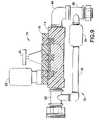
- FIG. 8is a side view of a still further valve assembly of the invention.
- FIG. 9is a side view of another valve assembly incorporating features of the invention.
- each numerical valueshould at least be construed in light of the number of reported significant digits and by applying ordinary rounding techniques.
- all ranges disclosed hereinare to be understood to encompass any and all subranges subsumed therein.
- a stated range of “1 to 10”should be considered to include any and all subranges between (and inclusive of) the minimum value of 1 and the maximum value of 10; that is, all subranges beginning with a minimum value of 1 or more and ending with a maximum value of 10 or less, e.g., 1 to 6.1, 3.5 to 7.8, 5.5 to 10, etc.
- All references referred to herein, such as but not limited to issued patents and published applications,are to be understood to be incorporated by reference in their entirety.
- FIGS. 1 and 2show an existing plastic bodied irrigation valve 10 which can be used as a starting point for the practice of the present invention.
- the specific structure and operation of this conventional valve 10is disclosed in U.S. Pat. No. 4,336,918 and, therefore, will not be described in detail.
- various selected elements of the valve 10will be described in order to clarify the subsequent discussion of the invention.
- This known irrigation valve 10is a diaphragm-type valve having a plastic valve housing 12 formed by a plastic valve body 14 and a cover 16 .
- the valve body 14has a flow passage extending therethrough with an inlet end 18 and an outlet end 20 .
- the cover 16is connected to the valve body 14 by a plurality of bolts 22 , such as aluminum or low-grade stainless steel bolts, threadably engagable with brass pressed insert nuts 24 in the valve body 14 .
- a diaphragm 26 of rubber or plasticis sandwiched between the valve body 14 and the cover 16 to form a seal between the two chambers of the valve 10 .
- a valve element(not shown) is positioned in the flow passage and engages the central region of the diaphragm 26 .
- the valve 10further includes a solenoid valve 28 threadably attached to the cover 16 and operationally connected with a vent system to control water pressure in a control chamber, as described in detail in U.S. Pat. No. 4,336,918.
- This vent systemincludes a crescent-shaped passage in flow communication on one end with the control chamber and on the other end with a vent outlet. The flow through the vent outlet is controlled by a plunger associated with the solenoid valve 28 , which can be moved to open or close the vent outlet.
- This conventional valve 10also includes a rotatable stop 30 that can be used to adjust or control the maximum opening position of the valve element.
- this valve 10does not meet the ASSE requirements and would not be acceptable for use in a waste water system.
- this existing valve 10can be modified such that the modified valve assembly can meet or exceed the ASSE requirements for waste water-systems and, therefore, can be used to replace the conventional metal valves used in existing waste water systems.
- FIGS. 3 and 4show a first modified valve assembly 40 utilizing the existing irrigation valve 10 but modifying the valve 10 in accordance with the invention to conform with ASSE requirements for use in a waste water system.
- the valve assembly 40includes an outlet adapter 42 attached to the outlet end 20 of the valve body 14 .
- the outlet adapter 42is configured to engage a vacuum breaker in a conventional waste water system.
- the outlet adapter 42can be a 1 inch by 1.5 inch (2.5 cm by 3.75 cm) plastic or metal adapter.
- the outlet adapter 42can engage the outlet end 20 of the valve body 14 in any conventional manner, such as by threads, and can have an external threaded region 44 configured to engage a conventional vacuum breaker.
- the valve assembly 40can also include a conventional street elbow 46 connected to the inlet end 18 of the valve body 14 .
- the elbow 46can be a conventional 1 inch (2.5 cm) diameter metal or plastic elbow.
- a conventional inlet tail piece assembly 48 having a nut, an O-ring, and slip ringcan be attached to the street elbow 46 .
- the inlet assembly 48allows the valve assembly 40 to be attached to a standard flush valve control stop in an existing waste water system.
- valve assembly 40In order for the valve assembly 40 to meet the ASSE requirements for use in a waste water system, one or more further modifications can be made to the existing valve 10 .
- the low-grade stainless steel or aluminum bolts 22 utilized with the conventional valve 10can be replaced by higher tensile bolts 50 , such as steel bolts.
- the brass pressed insert nuts 24can be replaced with steel insert nuts 52 .
- a steel washer 54can be added at one or more of the bolt locations to strengthen the valve assembly 40 .
- reinforcement plates 56can be connected at or between two or more of the bolt locations. These plates 56 can help distribute the force of the bolts 50 across more of the surface area of the cover 16 to help strengthen the connection between the valve body 14 and the cover 16 and prevent leaks at high pressure, e.g., pressures above 200 psi, such as above 300 psi, such as above 400 psi, such as above 500 psi.
- the reinforcement plates 56can be elongated metal or plastic strips that can have bores through which the bolts 50 can pass. The plates 56 can be positioned lengthwise on the valve cover 16 (as shown in FIG. 4 ) or can be positioned in a crosswise direction, if desired.
- the original diaphragm 26does not cover the entire mating surfaces of the valve body 14 to the cover 16 .
- the original diaphragm 26creates a seal of about 1/16 inch (0.16 cm) at the interface between the two chambers defined in the valve body 14 and the cover 16 .
- the cover 16 and valve body 14actually mate plastic to plastic.
- a gasket 60 of a suitable materialsuch as but not limited to synthetic, rubber, or plastic, can be added between the valve body 14 and the cover 16 to overlap the edges of the existing diaphragm 26 to create a seal across all or substantially all of the mating surfaces between the valve body 14 and the cover 16 .
- the diaphragm 26itself can be replaced with another diaphragm, e.g., rubber, synthetic, or plastic diaphragm, having a larger surface area to contact all or substantially all of the mating surface of the valve body 14 and the cover 16 to create a better seal than that in the conventional valve 10 .
- another diaphragme.g., rubber, synthetic, or plastic diaphragm
- FIG. 6shows another method of strengthening the existing valve housing to meet the ASSE requirements.
- one or more brackets 62such as conventional C-shaped threaded retaining brackets, can be positioned at one or more locations around the valve housing 12 .
- brackets 62would provide additional strength and support to the valve housing 12 to help resist leaks at high water pressures, such as at 500 psi or more.
- These brackets 62can be, for example, plastic or metal brackets, and can be removable from the valve housing 12 .
- FIG. 7shows another method of modifying the existing valve 10 for use in a waste water system.
- the cover 16can be disconnected from the valve body 14 and a layer of a conventional permanent adhesive 64 can be applied to the mating surfaces of the cover 16 and/or valve body 14 and then the components reconnected, such as by the original bolts 22 or higher tensile steel bolts 50 .
- FIG. 8shows an additional modified valve assembly 70 for use in a waste water system.
- a conventional pressure regulator 72can be positioned in the water flow path upstream of the valve 10 to reduce the pressure of the water before the water flows through the valve 10 .
- the pressure regulator 72can reduce the water pressure from a value of 500 psi or more on the inlet side of the pressure regulator 72 to a pressure of less than 500 psi, such as less than 400 psi, such as less than 300 psi, such as in the range of 50 psi to 200 psi, on the outlet side of the pressure regulator 72 .
- the known valve 10can be utilized since the water pressure should not be sufficient to cause leaks.
- one or more of the modifications described abovecan also be utilized to further strengthen the valve assembly 70 .
- FIG. 9shows another modified valve assembly 74 in accordance with the invention.
- a separate bypass assembly 76is provided.
- the bypass assembly 76includes a bypass conduit 78 extending from inlet piping 80 of the valve assembly 74 to outlet piping 82 of the valve assembly 74 , with a conventional pressure relief valve 84 located in the bypass conduit 78 .
- the pressure relief valve 84can be configured such that at a fluid pressure above a preset value, the pressure relief valve 84 opens to direct water flow around the valve 10 and, hence, decrease the inlet pressure on the valve housing 12 to a predetermined amount.
Landscapes
- Health & Medical Sciences (AREA)
- Life Sciences & Earth Sciences (AREA)
- Engineering & Computer Science (AREA)
- Hydrology & Water Resources (AREA)
- Public Health (AREA)
- Water Supply & Treatment (AREA)
- Valve Housings (AREA)
Abstract
Description
Claims (11)
Priority Applications (1)
| Application Number | Priority Date | Filing Date | Title |
|---|---|---|---|
| US11/246,457US7607448B2 (en) | 2004-10-08 | 2005-10-07 | Method for modifying a plastic body valve for use in a waste water system |
Applications Claiming Priority (2)
| Application Number | Priority Date | Filing Date | Title |
|---|---|---|---|
| US61726404P | 2004-10-08 | 2004-10-08 | |
| US11/246,457US7607448B2 (en) | 2004-10-08 | 2005-10-07 | Method for modifying a plastic body valve for use in a waste water system |
Publications (2)
| Publication Number | Publication Date |
|---|---|
| US20060076052A1 US20060076052A1 (en) | 2006-04-13 |
| US7607448B2true US7607448B2 (en) | 2009-10-27 |
Family
ID=36144073
Family Applications (1)
| Application Number | Title | Priority Date | Filing Date |
|---|---|---|---|
| US11/246,457Active2026-03-06US7607448B2 (en) | 2004-10-08 | 2005-10-07 | Method for modifying a plastic body valve for use in a waste water system |
Country Status (1)
| Country | Link |
|---|---|
| US (1) | US7607448B2 (en) |
Cited By (4)
| Publication number | Priority date | Publication date | Assignee | Title |
|---|---|---|---|---|
| US20090272922A1 (en)* | 2004-05-15 | 2009-11-05 | Bosko Robert S | Pressure-actuated normally open fluid valve |
| US20100218829A1 (en)* | 2004-10-08 | 2010-09-02 | I-Con Systems, Inc. | Diaphragm Valve With Electronic Pressure Detection |
| US9493936B2 (en) | 2004-10-08 | 2016-11-15 | Sdb Ip Holdings, Llc | System, method, and apparatus for monitoring wear in a flush valve using pressure detection |
| US10378676B2 (en) | 2015-12-15 | 2019-08-13 | Sdb Ip Holdings, Llc | System, method, and apparatus for optimizing a timing of a flush valve |
Families Citing this family (2)
| Publication number | Priority date | Publication date | Assignee | Title |
|---|---|---|---|---|
| US20160024760A1 (en)* | 2014-07-25 | 2016-01-28 | Jeremiah Cluff | Emergency water storage system |
| US11280252B2 (en)* | 2018-07-05 | 2022-03-22 | Hitachi Astemo, Ltd. | Control valve, flow rate control valve, and two-member connecting structure |
Citations (17)
| Publication number | Priority date | Publication date | Assignee | Title |
|---|---|---|---|---|
| US3987529A (en)* | 1971-11-01 | 1976-10-26 | Asahi Kasei Kogyo Kabushiki Kaisha | Valve and method for manufacturing the same |
| US4053136A (en)* | 1975-06-05 | 1977-10-11 | The Tappan Company | Control circuit and adjustable valve for a gas appliance |
| US4301992A (en) | 1979-12-06 | 1981-11-24 | Hydro-Rain Inc. | Diaphragm valve |
| US4336918A (en) | 1979-12-06 | 1982-06-29 | Hydro-Rain, Inc. | Diaphragm valve with multiple pivot axis valve element |
| US4440139A (en)* | 1981-07-20 | 1984-04-03 | Nippondenso Co., Ltd. | Vacuum control valve |
| US4477051A (en) | 1982-05-18 | 1984-10-16 | Ben Yehuda Avram | Flow control valve |
| US4672692A (en)* | 1984-09-07 | 1987-06-16 | Savage Nigel C | Bath with air jet |
| US4787413A (en) | 1985-12-11 | 1988-11-29 | Saggers Michael J | Pressure control valve |
| US4797820A (en) | 1986-07-28 | 1989-01-10 | Ansan Industries Limited | Programmable flow control valve unit with clock, program, automatic, manual, and repeat modes |
| US4893645A (en) | 1988-11-07 | 1990-01-16 | L. R. Nelson Corporation | Control valve with improved dual mode operation and flow adjustment |
| US5438714A (en) | 1989-10-31 | 1995-08-08 | Bauer Industries, Inc. | Fresh water manifold distribution system and method |
| US5575308A (en)* | 1995-08-21 | 1996-11-19 | Marandi; Ali | Torque-resisting anchor for irrigation valve |
| US5853026A (en) | 1994-08-30 | 1998-12-29 | The Toro Company | Valve with downstream manual bleed |
| US6109851A (en)* | 1999-01-13 | 2000-08-29 | Illinois Tool Works Inc. | Screws having selected heat treatment and hardening |
| US6164888A (en)* | 1998-05-04 | 2000-12-26 | Kocks; Leon B. | Self-lubricating cap nut |
| US6557580B2 (en) | 1999-05-26 | 2003-05-06 | The Toro Company | Self cleaning irrigation valve with offset manual on actuator, body/bonnet alignment, and captured screws |
| US7121556B2 (en)* | 2004-04-07 | 2006-10-17 | Freudenberg-Nok General Partnership | Molded plastic gasket |
- 2005
- 2005-10-07USUS11/246,457patent/US7607448B2/enactiveActive
Patent Citations (17)
| Publication number | Priority date | Publication date | Assignee | Title |
|---|---|---|---|---|
| US3987529A (en)* | 1971-11-01 | 1976-10-26 | Asahi Kasei Kogyo Kabushiki Kaisha | Valve and method for manufacturing the same |
| US4053136A (en)* | 1975-06-05 | 1977-10-11 | The Tappan Company | Control circuit and adjustable valve for a gas appliance |
| US4301992A (en) | 1979-12-06 | 1981-11-24 | Hydro-Rain Inc. | Diaphragm valve |
| US4336918A (en) | 1979-12-06 | 1982-06-29 | Hydro-Rain, Inc. | Diaphragm valve with multiple pivot axis valve element |
| US4440139A (en)* | 1981-07-20 | 1984-04-03 | Nippondenso Co., Ltd. | Vacuum control valve |
| US4477051A (en) | 1982-05-18 | 1984-10-16 | Ben Yehuda Avram | Flow control valve |
| US4672692A (en)* | 1984-09-07 | 1987-06-16 | Savage Nigel C | Bath with air jet |
| US4787413A (en) | 1985-12-11 | 1988-11-29 | Saggers Michael J | Pressure control valve |
| US4797820A (en) | 1986-07-28 | 1989-01-10 | Ansan Industries Limited | Programmable flow control valve unit with clock, program, automatic, manual, and repeat modes |
| US4893645A (en) | 1988-11-07 | 1990-01-16 | L. R. Nelson Corporation | Control valve with improved dual mode operation and flow adjustment |
| US5438714A (en) | 1989-10-31 | 1995-08-08 | Bauer Industries, Inc. | Fresh water manifold distribution system and method |
| US5853026A (en) | 1994-08-30 | 1998-12-29 | The Toro Company | Valve with downstream manual bleed |
| US5575308A (en)* | 1995-08-21 | 1996-11-19 | Marandi; Ali | Torque-resisting anchor for irrigation valve |
| US6164888A (en)* | 1998-05-04 | 2000-12-26 | Kocks; Leon B. | Self-lubricating cap nut |
| US6109851A (en)* | 1999-01-13 | 2000-08-29 | Illinois Tool Works Inc. | Screws having selected heat treatment and hardening |
| US6557580B2 (en) | 1999-05-26 | 2003-05-06 | The Toro Company | Self cleaning irrigation valve with offset manual on actuator, body/bonnet alignment, and captured screws |
| US7121556B2 (en)* | 2004-04-07 | 2006-10-17 | Freudenberg-Nok General Partnership | Molded plastic gasket |
Cited By (17)
| Publication number | Priority date | Publication date | Assignee | Title |
|---|---|---|---|---|
| US8539973B2 (en)* | 2004-05-15 | 2013-09-24 | Robert S. Bosko | Pressure-actuated normally open fluid valve |
| US20090272922A1 (en)* | 2004-05-15 | 2009-11-05 | Bosko Robert S | Pressure-actuated normally open fluid valve |
| US8695620B2 (en) | 2004-10-08 | 2014-04-15 | Sdb Ip Holdings, Llc | Method of monitoring wear in a diaphragm valve using pressure detection |
| US9279756B2 (en) | 2004-10-08 | 2016-03-08 | Sdb Ip Holdings, Llc | Method of monitoring wear in a diaphragm valve using pressure detection |
| US8215327B2 (en) | 2004-10-08 | 2012-07-10 | Sdb Ip Holdings, Llc. | Diaphragm valve with electronic pressure detection |
| US8261770B2 (en) | 2004-10-08 | 2012-09-11 | Sdb Ip Holdings, Llc. | Diaphragm valve controlled through electronic pressure detection and method |
| US8387653B2 (en) | 2004-10-08 | 2013-03-05 | Sdb Ip Holdings, Llc | Diaphragm valve with electronic pressure detection |
| US20100218833A1 (en)* | 2004-10-08 | 2010-09-02 | I-Con Systems, Inc. | Diaphragm Valve With Electronic Pressure Detection |
| US20100218829A1 (en)* | 2004-10-08 | 2010-09-02 | I-Con Systems, Inc. | Diaphragm Valve With Electronic Pressure Detection |
| US20100222930A1 (en)* | 2004-10-08 | 2010-09-02 | I-Con Systems, Inc. | Diaphragm Valve Controlled Through Electronic Pressure Detection and Method |
| US9389157B2 (en) | 2004-10-08 | 2016-07-12 | Sdb Ip Holdings, Llc | Method of monitoring wear in a diaphragm valve using pressure detection |
| US9493936B2 (en) | 2004-10-08 | 2016-11-15 | Sdb Ip Holdings, Llc | System, method, and apparatus for monitoring wear in a flush valve using pressure detection |
| US10378676B2 (en) | 2015-12-15 | 2019-08-13 | Sdb Ip Holdings, Llc | System, method, and apparatus for optimizing a timing of a flush valve |
| US10514110B2 (en) | 2015-12-15 | 2019-12-24 | Sdb Ip Holdings, Llc | System, method, and apparatus for optimizing a timing of a flush valve |
| US10527191B2 (en) | 2015-12-15 | 2020-01-07 | Sdb Ip Holdings, Llc | System, method, and apparatus for monitoring restroom appliances |
| US11156309B2 (en) | 2015-12-15 | 2021-10-26 | Sdb Ip Holdings, Llc | System, method, and apparatus for monitoring restroom appliances |
| US12007042B2 (en) | 2015-12-15 | 2024-06-11 | Sdb Ip Holdings, Llc | System, method, and apparatus for monitoring restroom appliances |
Also Published As
| Publication number | Publication date |
|---|---|
| US20060076052A1 (en) | 2006-04-13 |
Similar Documents
| Publication | Publication Date | Title |
|---|---|---|
| US7784483B2 (en) | Backflow preventer | |
| US8201576B2 (en) | Reinforced elastomeric hinge check valve | |
| US9222582B2 (en) | Main valve with internal rigid structure | |
| US7607448B2 (en) | Method for modifying a plastic body valve for use in a waste water system | |
| US5388805A (en) | Dual seal for shut-off valve | |
| US8490646B2 (en) | Diaphragm valve with mechanical pressure relief | |
| US3304048A (en) | Balanced valve | |
| CN101484646B (en) | Control stop and flushing system | |
| US4506694A (en) | Relief valve assembly for use with backflow preventers | |
| AU2002323893A1 (en) | Water Hammer Arrester | |
| KR101180352B1 (en) | operating pressure indicating type pressure regulating valve | |
| US4553563A (en) | Relief valve assembly for use with backflow preventers | |
| CN210372193U (en) | Pilot valve for hydraulic control valve | |
| CN201844081U (en) | Pipeline overflow valve | |
| CN208417595U (en) | A kind of novel and multifunctional valve | |
| CN221374542U (en) | Multilayer sealing ball valve | |
| CN221257793U (en) | Pressure reducing valve resistant to high-pressure backflow | |
| CN220151996U (en) | Ceramic core valve with high sealing performance | |
| CN212055914U (en) | A kind of valve for fermentation system | |
| NO310988B1 (en) | safety valve | |
| US20240264614A1 (en) | Water pressure regulator assembly | |
| CN211398704U (en) | Side water stop structure of sand flushing valve arc-shaped working gate | |
| CN204828861U (en) | A new plastic stool sensor flush valve | |
| RU2217637C2 (en) | Valve-distributor | |
| CN208041254U (en) | A kind of low pressure loss voltage-regulation voltage-stabilization protection valve |
Legal Events
| Date | Code | Title | Description |
|---|---|---|---|
| AS | Assignment | Owner name:I-CON SYSTEMS, FLORIDA Free format text:ASSIGNMENT OF ASSIGNORS INTEREST;ASSIGNORS:HAWKS JR., WILLIAM ROBERT;BUSH, SHAWN D.;REEL/FRAME:017082/0508 Effective date:20051006 | |
| STCF | Information on status: patent grant | Free format text:PATENTED CASE | |
| CC | Certificate of correction | ||
| AS | Assignment | Owner name:SDB IP HOLDINGS, LLC., FLORIDA Free format text:ASSIGNMENT OF ASSIGNORS INTEREST;ASSIGNOR:BUSH, SHAWN D.;REEL/FRAME:025341/0382 Effective date:20100623 Owner name:BUSH, SHAWN D., FLORIDA Free format text:ASSIGNMENT OF ASSIGNORS INTEREST;ASSIGNOR:I-CON SYSTEMS, INC.;REEL/FRAME:025346/0781 Effective date:20100101 | |
| FPAY | Fee payment | Year of fee payment:4 | |
| AS | Assignment | Owner name:PNC BANK, NATIONAL ASSOCIATION, NORTH CAROLINA Free format text:SECURITY INTEREST;ASSIGNOR:I-CON SYSTEMS, INC;REEL/FRAME:030716/0975 Effective date:20130528 | |
| FPAY | Fee payment | Year of fee payment:8 | |
| MAFP | Maintenance fee payment | Free format text:PAYMENT OF MAINTENANCE FEE, 12TH YR, SMALL ENTITY (ORIGINAL EVENT CODE: M2553); ENTITY STATUS OF PATENT OWNER: SMALL ENTITY Year of fee payment:12 | |
| AS | Assignment | Owner name:I-CON SYSTEMS, INC, FLORIDA Free format text:RELEASE BY SECURED PARTY;ASSIGNOR:PNC BANK, NATIONAL ASSOCIATION;REEL/FRAME:070078/0905 Effective date:20241216 | |
| FEPP | Fee payment procedure | Free format text:ENTITY STATUS SET TO UNDISCOUNTED (ORIGINAL EVENT CODE: BIG.); ENTITY STATUS OF PATENT OWNER: LARGE ENTITY |