US7606683B2 - Cooling system design simulator - Google Patents
Cooling system design simulatorDownload PDFInfo
- Publication number
- US7606683B2 US7606683B2US10/765,820US76582004AUS7606683B2US 7606683 B2US7606683 B2US 7606683B2US 76582004 AUS76582004 AUS 76582004AUS 7606683 B2US7606683 B2US 7606683B2
- Authority
- US
- United States
- Prior art keywords
- parameters
- flow control
- refrigerant
- compressor
- generating
- Prior art date
- Legal status (The legal status is an assumption and is not a legal conclusion. Google has not performed a legal analysis and makes no representation as to the accuracy of the status listed.)
- Active, expires
Links
Images


Classifications
- F—MECHANICAL ENGINEERING; LIGHTING; HEATING; WEAPONS; BLASTING
- F25—REFRIGERATION OR COOLING; COMBINED HEATING AND REFRIGERATION SYSTEMS; HEAT PUMP SYSTEMS; MANUFACTURE OR STORAGE OF ICE; LIQUEFACTION SOLIDIFICATION OF GASES
- F25B—REFRIGERATION MACHINES, PLANTS OR SYSTEMS; COMBINED HEATING AND REFRIGERATION SYSTEMS; HEAT PUMP SYSTEMS
- F25B49/00—Arrangement or mounting of control or safety devices
- G—PHYSICS
- G06—COMPUTING OR CALCULATING; COUNTING
- G06F—ELECTRIC DIGITAL DATA PROCESSING
- G06F30/00—Computer-aided design [CAD]
- G06F30/20—Design optimisation, verification or simulation
- G—PHYSICS
- G06—COMPUTING OR CALCULATING; COUNTING
- G06F—ELECTRIC DIGITAL DATA PROCESSING
- G06F2119/00—Details relating to the type or aim of the analysis or the optimisation
- G06F2119/08—Thermal analysis or thermal optimisation
Definitions
- the present inventionrelates to cooling systems, and more particularly to simulating performance of a cooling system.
- Traditional cooling systemssuch as refrigeration and air-conditioning systems, include a compressor, a condensing unit, an expansion valve and an evaporator.
- the compressorcompresses gaseous refrigerant exiting the evaporator and discharges the high pressure refrigerant to the condensing unit.
- the condensing unitoperates as a heat exchanger enabling heat transfer from the gaseous refrigerant to a heat sink (e.g., air or water).
- the refrigerantcondenses within the condensing unit and a state change occurs from gas to liquid.
- the liquid refrigerantexits the condensing unit and flows to the evaporator through the expansion valve.
- the evaporatoralso operates as a heat exchanger enabling heat transfer from the atmosphere surrounding the evaporator to the liquid refrigerant. As the heat transfer occurs, the temperature of the refrigerant increases until a state change occurs from liquid to gas. The gas refrigerant is drawn into the suction side of the compressor and the cooling cycle continues.
- the present inventionprovides a method of computer-based simulation of a cooling system.
- the methodincludes inputting condenser parameters, evaporator parameters and compressor parameters for the cooling system.
- the condenser parameters, the evaporator parameters and the compressor parametersare processed through a model of the cooling system.
- a flow control deviceis selected based on an output of the model.
- the flow control deviceincludes one of a capillary tube device and an orifice device.
- the methodfurther includes selecting a flow control parameter including a sub-cooling temperature and a superheat temperature.
- the step of selecting a flow control deviceincludes generating a list of available flow control devices based on the output and selecting the flow control device from the list of available flow control devices.
- the methodfurther includes inputting refrigerant properties for a refrigerant flowing through the cooling system.
- the outputis further based on the refrigerant properties.
- the refrigerant propertiesinclude refrigerant charge and one of refrigerant superheat temperature and refrigerant sub-cooling temperature.
- the step of inputting condenser parametersincludes generating a list of available condensers, selecting a condenser from the list of available condensers and automatically inputting the condenser parameters based on the selected condenser.
- the step of inputting compressor parametersincludes generating a list of available compressors based on search parameters, selecting a compressor from the list of available compressors and automatically inputting the compressor parameters based on the selected compressor.
- the search parametersinclude at least one of a model number, a voltage, a phase, a frequency, a refrigerant type, an application type and a capacity.
- the search parametersinclude a capacity and a capacity tolerance.
- the methodfurther includes inputting tubing and line heat transfer parameters.
- the outputis further based on the tubing and line heat transfer parameters.
- the methodfurther includes inputting accumulator parameters.
- the outputis further based on the accumulator parameters.
- the condenser parameters and the compressor parametersare input as air-cooled condensing unit parameters.
- the methodfurther includes generating a list of available air-cooled condensing units, selecting an air-cooled condensing unit from the list of available air-cooled condensing units and automatically inputting the air-cooled condensing unit parameters based on the selected air-cooled condensing unit.
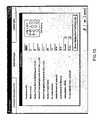
- FIG. 1is a schematic illustration of an exemplary cooling system
- FIG. 2is a flowchart illustrating general steps of a cooling system design simulator according to the present invention
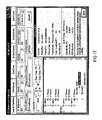
- FIG. 3is a screen-shot illustrating software-based input of cooling system component information
- FIG. 4is a screen-shot illustrating system type and operation mode inputs
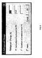
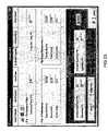
- FIG. 5is a screen-shot illustrating refrigerant charge inputs
- FIG. 6is a screen-shot illustrating sub-cooling and superheat parameter inputs for flow control
- FIG. 7is a screen-shot illustrating capillary tube flow control device inputs
- FIG. 8is a screen-shot illustrating orifice flow control device inputs
- FIG. 9is a screen-shot illustrating evaporator entering air temperature and air flow inputs
- FIG. 10is a screen-shot illustrating evaporator heat exchanger inputs
- FIG. 11is a screen-shot illustrating evaporator scaling factor inputs
- FIG. 12is a screen-shot illustrating condenser entering temperature and air flow inputs
- FIG. 13is a screen-shot illustrating condenser heat exchanger inputs
- FIG. 14is a screen-shot illustrating condenser scaling factor inputs
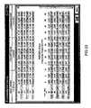
- FIG. 15is a screen-shot illustrating a condenser database
- FIG. 16is a screen-shot illustrating compressor search and selection inputs
- FIG. 17is a screen-shot illustrating compressor search results
- FIG. 18is a screen-shot illustrating compressor rated capacity values
- FIG. 19is a screen-shot illustrating compressor rated power values
- FIG. 20is a screen-shot illustrating compressor search inputs based on user specified capacity
- FIG. 21is a screen-shot illustrating compressor displacement and EER scaling
- FIG. 22is a screen-shot illustrating a compressor operating envelope
- FIG. 23is a screen-shot illustrating re-rated compressor capacity
- FIG. 24is a screen-shot illustrating cooling mode tubing and line heat transfer inputs
- FIG. 25is a screen-shot illustrating heating mode tubing and line heat transfer inputs
- FIG. 26is a screen-shot illustrating an accumulator database
- FIG. 27is a screen-shot illustrating accumulator geometry inputs
- FIG. 28is a screen-shot illustrating air-cooled condensing unit (ACU) selection
- FIG. 29is a screen-shot illustrating ACU selection inputs
- FIG. 30is a screen-shot illustrating a selected ACU summary
- FIG. 31is a screen-shot illustrating ACU components details
- FIG. 32is a screen-shot illustrating ACU compressor capacity based on evaporator temperature and condensing temperature
- FIG. 33is a screen-shot illustrating ACU compressor power based on evaporator temperature and condensing temperature
- FIG. 34is a screen-shot illustrating ACU condenser details
- FIG. 35is a screen-shot illustrating ACU key features
- FIG. 36is a screen-shot illustrating a key feature comparison between ACUs
- FIG. 37is a screen-shot illustrating ACU search results based on the ACU's capacity
- FIG. 38is a screen-shot illustrating refrigerant saturated properties inputs
- FIG. 39is a screen-shot illustrating refrigerant superheated properties inputs
- FIG. 40is a screen-shot illustrating refrigerant liquid properties inputs
- FIG. 41is a screen-shot illustrating key simulation inputs
- FIG. 42is a screen-shot illustrating simulation results in graphical format
- FIG. 43is a screen-shot illustrating flow control sizes selection
- FIG. 44is a screen-shot illustrating sizes of flow control devices based on the simulation results
- FIG. 45is a screen-shot illustrating thermal expansion valve (TXV) selection based on the simulation results
- FIG. 46is a screen-shot illustrating a psychrometric calculator used to calculate moist air properties
- FIG. 47is a screen shot illustrating a psychrometric chart graphically displaying moist air properties.
- FIG. 48is a screen-shot illustrating manufacturer engineering bulletins provided by the cooling system design simulator.
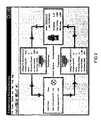
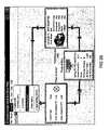
- a generic cooling system 10includes a compressor 12 , a condenser 14 , an expansion valve 16 and an evaporator 18 .
- the compressor 12is controlled by a controller 20 and compresses gaseous refrigerant exiting the evaporator 18 .
- the compressor 12discharges the high pressure refrigerant to the condenser 14 .
- the condenser 14operates as a heat exchanger enabling heat transfer (Q 1 ) from the gaseous refrigerant to a heat sink (e.g. air or water).
- the refrigerantcondenses within the condenser 14 and a state change occurs from gas to liquid.
- the liquid refrigerantexits the condenser 14 and flows to the evaporator 18 through the expansion valve 16 .
- the evaporator 18also operates as a heat exchanger enabling heat transfer (Q 2 ) from the atmosphere surrounding the evaporator 18 to the liquid refrigerant. As the heat transfer occurs, the temperature of the refrigerant increases until a state change occurs from liquid to gas. The gas refrigerant is drawn into the suction side of the compressor 12 and the cooling cycle continues.
- the cooling system design simulatorincludes a series of sub-routines to determine the performance of the individual components of exemplary cooling systems and the cooling system 10 as a whole. More particularly, the design simulator performs steady-state design and analysis of vapor compression air-to-air-systems operating in either heating and cooling modes.
- a cooling system modelis based on underlying physical principles and generalized correlations to avoid the limitations of empirical correlations derived from manufacturer specifications. As a hardware-based model, a user can specify the individual component parameters and define the geometry of tubing connecting the cooling system components.
- the design simulatoris preferably provided as a software-based computer program. More specifically, the design simulator is preferably a Windows interface that is functionality integrated in the software to enable quick cooling system design. Other complimentary functions are integrated to streamline design efforts. These include, but are not limited to look-up tables for refrigerant and psychrometric properties of air.
- step 100the user selects the operating mode of the cooling system (i.e., cooling or heating).
- step 102the user specifies the refrigerant charge.
- the userselects the flow control in step 104 .
- step 106the user inputs evaporator data and determines whether the cooling system includes an air-cooled condensing unit (ACU) in step 108 . If the cooling system does include an ACU, the simulator continues in step 110 . If the cooling system does not include an ACU, the simulator continues in step 112 .
- ACUair-cooled condensing unit
- step 110the user inputs the ACU data.
- step 112the user inputs compressor data and the user inputs condenser data in step 114 .
- step 116the user inputs tubing and line heat transfer data for the plumbing between components of the cooling system.
- step 118the user determines whether the cooling system includes an accumulator. If the cooling system does include an accumulator, the simulator continues in step 120 . If the cooling system does not include an accumulator, the simulator continues in step 122 .
- step 120the user inputs accumulator data.
- step 122the user inputs refrigerant properties.
- step 124the user runs the simulation based on the input data and simulation ends.
- FIGS. 3 through 45generally provide screen-shots of a software-based implementation of the cooling system design simulator. More particularly, FIG. 3 is a screen-shot illustrating a generic cooling system schematic. As similarly described above with reference to FIG. 1 , the cooling system schematic includes a condenser, a flow control device, an evaporator and a compressor. The cooling system can be simulated in either a cooling mode or a heating mode. The user selects the operating mode by clicking on Inputs in the toolbar and selecting the System Type and Operation Mode option.
- FIG. 4illustrates a screen-shot of a system type and mode screen. The user can select between an A/C system operating in respective cooling and heating modes or a refrigeration system operating in a cooling mode. The user can also enter a simulation title and notes.
- the usercan specify the refrigerant charge for the cooling system or have the simulator calculate the refrigerant charge from the other system parameters.
- the usercan input the refrigerant charge data by clicking on Inputs in the toolbar and selecting the Specify Refrigerant Charge and Edit Inputs option.
- FIG. 5illustrates a screen-shot of the refrigerant charge menu. The user can input the refrigerant charge in lbs and either the sub-cooling temperature (° F.) at the condenser discharge or the superheat temperature (° F.) at the compressor inlet.
- the simulatorenables the user to select between flow control device options.
- the optionsinclude capillary tube and orifice.
- the usercan specify flow control parameters including the condenser discharge sub-cooling temperature (° F.) and the compressor inlet superheat temperature (° F.).
- the simulatorcalculates the equivalent Thermal Expansion Valve (TXV), capillary tube and orifice sizes to achieve these conditions, as described in further detail below.
- TXVThermal Expansion Valve
- the flow controlis selected by clicking on Inputs in the toolbar and choosing the Flow Control menu or by clicking on the flow control illustration.
- FIG. 6provides a screen-shot of the Flow Control Devices screen with the sub-cooling/superheat parameters option selected. The user inputs the sub-cooling and superheat temperatures.
- FIG. 7provides a screen-shot of the Flow Control Devices screen with the capillary tube device selected. The user inputs the superheat temperature, number of parallel capillary tubes, inside diameter of the capillary tube(s) and the length of the capillary tube(s).
- FIG. 8provides a screen-shot of the Flow Control Devices screen with the orifice device selected. The user inputs the superheat temperature, the number of parallel short tube orifices, the inside diameter of the short tube orifice(s) and the length of the short tube orifice(s).
- the data for the evaporatoris entered by opening the evaporator screen.
- the usercan access this screen by either choosing Inputs on the toolbar and the Evaporator option or by clicking on the evaporator image.
- the evaporatorrequires several inputs that are grouped into three categories: (i) entering air condition (dry bulb and wet bulb temperature) and air flow rate/fan power, (ii) heat exchanger physical properties and (iii) scaling factors to adjust simulation results to match with measured system performance data.
- Expert tipsare included on each input screen to help the user streamline their design efforts. The expert tips are accessed by choosing the icon with question mark.
- FIG. 9provides a screen-shot of an Entering Air and Fan input screen.
- the userinputs the entering air information including the dry bulb temperature (° F.) and the wet bulb temperature (° F.).
- the useralso inputs the fan information including the air flow rate (Ft 3 /Min) and power input (Watts).
- FIG. 10provides a screen-shot of a Heat Exchanger input screen.
- the userinputs geometry information including frontal area (Ft 2 ), number of rows, number of equivalent, parallel refrigerant circuits, horizontal tube spacing, vertical tube spacing and number of return bends.
- the geometry informationfurther includes fin density, outside diameter of tubing, inside diameter of tubing, tubing type (e.g., smooth, rifled) and fin type (e.g., smooth, wavy, louvered).
- FIG. 11provides a screen-shot of a Scaling Factors input screen.
- the scaling factorsare divided into air side and refrigerant side groups.
- the air side groupincludes heat transfer and pressure drop scaling factors.
- the refrigerant side groupalso includes heat transfer and pressure drop scaling factors.
- the scaling factorsenable the user to adjust the simulation results to match measured system performance.
- the data for the condenseris entered by opening the condenser screen.
- the useraccesses this screen either by choosing Inputs on the toolbar and the Condenser menu or by clicking on the condenser image on the main screen.
- the userinputs entering air temperature data and fan parameters.
- the entering air temperature dataincludes dry bulb temperature (° F.) and wet bulb temperature (° F.).
- the fan parametersinclude air flow rate (ft 3 /min) and power input (Watts).
- FIG. 13provides a screen-shot of a Condenser Heat Exchanger input screen.
- the userinputs geometry information including frontal area (Ft 2 ), number of rows, number of equivalent parallel refrigerant circuits, horizontal tube spacing, vertical tube spacing and number of return bends.
- the geometry informationfurther includes fin density, outside diameter of tubing, inside diameter of tubing, tubing type (e.g., smooth, rifled) and fin type (e.g., smooth, wavy, louvered).
- FIG. 14provides a screen-shot of a condenser Scaling Factors input screen.
- the scaling factorsare divided into air side and refrigerant side groups.
- the air side groupincludes heat transfer and pressure drop scaling factors.
- the refrigerant side groupalso includes heat transfer and pressure drop scaling factors.
- the scaling factorsenable the user to adjust the simulation results to match laboratory measured system performance.
- the usercan select a specific condenser from a list of available models.
- the useraccesses a database by clicking on the Show Refrigeration Condenser List button on the bottom right corner of Heat Exchanger input screen.
- a table with condenser informationappears.
- the userscrolls through the condenser list to find the condenser model that meets system requirements.
- the condenser listis initially ordered by condenser part number.
- the usercan re-order the condenser list by another parameter by clicking on that parameter in the top row of condenser list.
- Condenser geometry parametersare automatically entered in the appropriate fields of the Condenser screen when user selects a condenser by double clicking on the condenser part number.
- An engineering drawing of a particular condenser(no shown) is provided at the users request.
- the usercan access a database of manufacturer's compressors (both air-conditioning and refrigeration compressors models).
- the usercan search and view the details of all available compressors.
- the compressor detailsinclude compressor type (e.g., semi-hermetic, hermetic, scroll, etc.), application type (e.g., refrigeration and air-conditioning), temperature range (e.g., air-conditioning, medium temp. high temp., etc.), voltage, frequency, capacity, power, amps, compressor operating envelope and re-rating of compressor performance to a user specified condition.
- the compressor selection screenis accessed either by choosing Inputs from the toolbar and Compressor menu or by clicking on the compressor image in the main screen.
- the compressor databasecan be searched by entering a known compressor model in the Model Name field and clicking the Search button.
- the model namecan be complete or partial. For example, if the user enters the model name as ZR34K3-PFV and Refrigerant R-22, the search is very specific and only the ZR34K3-PFV compressor will show up in the search result. However, if the user enters the model name as ZR, all the models starting with ZR will appear in the compressor result list.
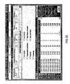
- the search settings and the resultsinclude compressor model (e.g., ZR34K3), voltage, phase and frequency, application (e.g., air-conditioning), product type (e.g., scroll), capacity, power and energy efficiency ratio (EER) at a specified rating point (e.g., 45° F. Evaporator, 130° F. Condenser), record date and tested condition (e.g., return gas temperature/superheat and subcooling).
- Capacity, power and current (amp) data over the entire operating range of the compressorare shown in the Rated Capacity, Rated Power and Current tabs, FIGS. 18 and 19 , respectively, once a compressor model is selected from the generated compressor list.
- the usercan search the compressor database based on a specified capacity range.
- the userenters a capacity and specifies a capacity tolerance ( ⁇ 5% to ⁇ 50%), refrigerant, application and product type and clicks on the Search button.
- a capacity tolerance⁇ 5% to ⁇ 50%)
- refrigerant⁇ 5% to ⁇ 50%
- the search buttonFor example, if the user enters the capacity as 34,000 Btu/hr with a capacity tolerance of ⁇ 10% to +10%, 45° F. evaporator temperature, 130° F. condensing temperature, application type as air-conditioning, product type as scroll and refrigerant as R-22 the search lists several corresponding compressor models. Capacity, power and current information are displayed when the user selects a particular compressor model from the compressor list. Compressor models that are obsolete are highlighted.
- the useris also able to scale compressor displacement, Energy Efficiency Ratio (EER) or both compressor displacement and EER.
- EEREnergy Efficiency Ratio
- scalingis provided for 50 Hz and 60 Hz.
- 50 Hz performance datais derived by applying the ratio of 0.83 to the displacement of the given compressor. This feature may be accessed by selecting the Rated Capacity or Rated Power tabs, checking the Scale Performance option and the Displacement option in the Selection box. The user inputs a scaling factor in the Displacement section. Removing the check mark from the Scale Performance box resets the data to its original state.
- EER scalingenables the user to alter the power of the compressor without changing the capacity.
- EER scalingis accessed by opening the Rated Capacity or Rated Power tabs, checking the Scale Performance box and selecting the EER option in the Selection box. The user inputs the scaling factor in the EER box. Removing the check mark from Scale Performance box resets the data to its original state.
- Scaling both displacement and EERenables the user to simultaneously scale both the capacity and the power of the compressor. Scaling both displacement and EER is accessed by opening the Rated Capacity or Rated Power tabs, checking the Scale Performance box and selecting Both in the Selection box. The user inputs scaling factors for both Displacement and EER in their respective boxes. Removing the check mark from Scale Performance box resets the data to its original state.
- FIG. 22the user can perform a compressor envelope check on the capacity, power and current (amp) data. This procedure automatically deletes any performance data that falls outside the boundaries of the compressor operating envelope.
- the operating envelope checkis activated by choosing the Apply Envelope Check button in the Rated Capacity, Rated Power or Rated Current tabs. This feature may also be accessed by choosing the Operating Envelope icon located in the top left hand corner of the Rated Capacity, Rated Power and Rated Current tabs.
- FIG. 22illustrates an exemplary compressor operating envelope with the user selected operating condition of 45° F./120° F. (evaporator temperature/condenser temperature) marked with a dot.
- the compressor performance data shown in the Rated Capacity, Rated Power, Rated Current tabsare the performance at the compressors rated condition.
- the usercan re-rate the compressor performance data at a condition other than the rated condition.
- Compressor re-ratingcan be performed over the entire operating range or on a single operating point (i.e. at a user specified condensing and evaporator temperature) of the compressor.
- the useris notified if an operating point outside the compressor operating envelope is entered.
- the userselects the Re-Rated Capacity or Re-Rated Power tabs and selects the Matrix option.
- the userenters new operating conditions in the Re-Rated Conditions section, including return gas temperature, constant superheat and sub-cooling temperatures.
- the usermay also check the re-rated conditions against the compressor operating envelope by selecting the Re-Rate With Envelope Check box. The user presses the Re-Rate button to view the re-rated performance.
- the cooling system design simulatoralso simulates the system design based on tubing and line heat transfer data.
- the tubing and line heat transfer datais entered by opening the Connecting Tubing and Line Heat Transfer screen. The user accesses this screen either by choosing Inputs from the toolbar and the Tubing and Line Heat Transfer menu or by clicking on the tubing and line images on the main screen.
- the tubing and line heat transfer datarequires several inputs.
- the inputs requiredare operation mode dependent. In other words, the inputs vary between heating and cooling modes.
- the required inputsare grouped in categories that include inside tubing diameter, equivalent tubing lengths and shell heat loss rate factor and line heat transfer.
- the inside tubing diameter groupincludes liquid line, vapor line from evaporator to compressor and discharge line from compressor to condenser.
- the equivalent tubing length groupincludes liquid line, vapor line from evaporator to compressor and discharge line from compressor to condenser.
- the shell loss and heat transfer groupincludes compressor shell heat loss rate factor, heat loss rate in compressor discharge line, heat gain in compressor suction line and heat loss rate in liquid line.
- the compressor shell heat loss rateis defined as the fraction of the compressor power input into the system.
- the inside tubing diameter groupincludes liquid line, vapor line from reversing valve to condenser, vapor line from reversing valve to evaporator, suction line from reversing valve to compressor and discharge line from compressor to reversing valve.
- the equivalent tubing length groupincludes liquid line, vapor line from reversing valve to condenser, vapor line from reversing valve to evaporator, suction line from reversing valve to compressor and discharge line from compressor to reversing valve.
- the shell loss and heat transfer groupincludes compressor shell heat loss rate factor, heat loss rate in compressor discharge line, heat gain in compressor suction line and heat loss rate in liquid line.
- the usercan add an accumulator to the cooling system simulation.
- the userselects the Accumulator under the Options menu in the main screen.
- An Accumulator imageappears in the main screen between the evaporator and the compressor.
- unselect the Accumulator under the Options menuunselect the Accumulator under the Options menu.
- the usercan input the accumulator configuration parameters including shell, J-tube and compressor.
- the shell parametersinclude internal height and internal diameter.
- the J-tube parametersinclude internal diameter, oil return hole lower diameter, oil return hole upper diameter and spacing between oil return holes.
- the compressor parametersinclude estimated free internal volume.
- the usercan select an accumulator from an accumulator database, which automatically inputs the configuration parameters.
- the userBy clicking on the Show Accumulator List button, the user is able to browse the database of available accumulators.
- the databaseis initially ordered by part number (P/N) field.
- the usercan re-order the list by clicking the desired parameter on the top row (header row).
- An accumulatoris selected from the list by double clicking on the desired accumulator P/N.
- the system design simulatorenables the user to design a system including an air-cooled condensing unit (ACU).
- ACUair-cooled condensing unit
- the usercan include an ACU by clicking on Condensing Unit under the Options menu in the main screen.
- the cooling system graphicis altered to illustrate the ACU (i.e., combined compressor and condenser).
- the usercan select an available ACU from an ACU database.
- a search toolis provided so that the user can quickly search and view the details of the available ACU's that meet the design need.
- the ACU selection screenshows a variety of search criteria available for finding the proper ACU.
- the search criteriacan be a single or a combination of parameters.
- the search criteriainclude refrigerant type, temperature range, frequency, phase, voltage, ranges of physical dimensions (i.e., length, width, height), nominal horsepower (Hp) or capacity.
- the searchis initiated by choosing the Search button and the result yields a list of ACU's matching the user specified criteria.
- An ACUis selected by double clicking the model.
- the Component Details tabprovides pertinent information about the selected ACU.
- the Compressor tab under Components Detailshows the compressor performance (capacity and power) (see FIGS. 32 and 33 ).
- the Condenser tabillustrates condenser geometry and the Accumulator tab provides accumulator geometry (see FIG. 34 ). Accumulator details are provided only if the particular ACU is equipped with an accumulator.
- the Condenser tabenables the user to enter inputs for the entering air condition.
- the usercan view a reference drawing of the ACU illustrating the component layout. As illustrated in FIG. 31 , the user can view the details of the selected ACU by clicking on the ACU tab (e.g. C3AH-0303-TAC-001).
- the system design simulatoridentifies the key features of the selected ACU.
- the key featurescan include shut-off valves, receiver, accumulator, pressure controls and the like.
- the key featuresdo not impact the ACU's thermal performance but are provided to enhance the ACU's functionality.
- the usercan view the ACU's key features by moving the mouse over the lower half of the screen.
- the check mark againstshows the key items included in the feature list for the selected ACU.
- the key features availablemay vary with the ACU model line. However, the thermal performance of both units is same as long as the first nine characters of the model and the operating frequency of the units are same. As illustrated in FIG. 36 , the user can compare key features of multiple ACU's.
- the ACU search resultscan be displayed either in an explorer tree by selecting Explorer Tree in the Results In field or in a Spread Sheet format (see FIG. 29 ) by selecting Spread Sheet.
- the user selected format preference for displaywill remain in-force until the user changes the display format. It should be noted, however, that the search criteria for both formats are identical.
- the ACU model ACU line (C, F, etc), unit's electrical, capacity (Hp)are color coded to assist user navigation.
- the system design simulatorprovides the thermodynamic properties of refrigerants including saturated properties, superheated properties and liquid properties.
- the refrigerantsinclude, but are not limited to, R-12, R-22, R-502, R-134a, R-404A, R-507 and R-410A.
- the saturation pressurecan be determined based on temperature by choosing the Saturated Tab and entering the temperature (see FIG. 38 ). The corresponding saturation pressure is given by clicking on the Calculate button. The saturation temperature can similarly be determined based on pressure.
- the vapor propertiescan be determined by clicking on the Vapor Properties tab and inputting pressure and temperature (see FIG. 39 ).
- the properties including specific volume, enthalpy and entropyare provided by clicking on the Calculate button.
- the enthalpycan be determined based on the pressure and entropy by clicking on the corresponding Calculate button.
- the liquid propertiesare determined by clicking on the Liquid Properties tab and inputting temperature (see FIG. 40 ).
- the properties including density, specific volume, enthalpy and latent heat vaporare provided by clicking on the Calculate button.
- the design simulatoris run by choosing the Run option on the menu bar and clicking Run Model.
- the design simulatorcan also be run by clicking the Run icon on the toolbar.
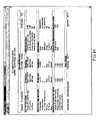
- the resultsare provided in tabular and graphical formats. More particularly, a summary table is provided, listing the key system inputs and the parameters for the individual components (see FIG. 41 ). Alternatively, a graphical illustration of the cooling system is shown with the corresponding parameters listed adjacent to images of the individual components (see FIG. 42 ).
- the resultscan be printed by choosing the File menu, Print and Outputs options from the main screen or by clicking on the Print icon. Additionally, the results can be saved to an electronic file by choosing the File menu, Save option or by clicking on the Save icon.
- the overall system parametersinclude mode, system capacity, compressor power, evaporator fan power, condenser fan power, total power, system EER, sensible heat ratio, compressor model number, refrigerant and refrigerant charge.
- the condenser air flow parametersinclude inlet air temperature, air flow rate and outlet air temperature.
- the condenser inlet refrigerant parametersinclude pressure, temperature, saturation temperature and enthalpy.
- the condenser outlet refrigerant propertiesinclude pressure temperature, saturation temperature and sub-cooling temperature.
- the flow control inlet refrigerant propertiesinclude pressure, temperature, saturation temperature and sub-cooling temperature.
- the evaporator air flow propertiesinclude inlet air temperature, air flow rate and outlet air temperature.
- the evaporator inlet refrigerant parametersinclude pressure, temperature, enthalpy and refrigerant flow rate.
- the evaporator outlet refrigerant parametersinclude pressure, temperature, saturation temperature, enthalpy and superheat temperature.
- the compressor suction refrigerant parametersinclude pressure, temperature, saturation temperature, enthalpy and superheat temperature.
- the compressor discharge refrigerant propertiesinclude pressure, temperature, saturation temperature and enthalpy.
- the cooling system design simulatorenables the user to view flow control device sizing based on the simulation results.
- the userselects View menu and Flow Control Sizes option from the main screen after running the system simulation. This capability is available only when the sub-cooling and compressor superheat option is selected as the flow control devices option.
- An exemplary flow control sizes screen with thermal expansion valve (TXV), capillary tube and orifice sizing parametersis illustrated in FIG. 44 .
- the cooling system design simulatorenables a user to select a TXV based on the simulation results. This function is chosen by clicking on the Flow Controls TXV Selection button (see FIG. 44 ).
- the flow control TXV selection screenis shown in FIG. 45 . Selection parameters including refrigerant, percent bleed, evaporator, condensing, liquid temperature, and evaporator capacity are automatically entered based on the results of the system simulation. A provision has been provided so that the user may directly enter the required data for selecting TXV without running the system simulation. The user may enter other selection criteria such as valve type series, connection type, strainer, distributor type and valve loading range. A list of the available TXV's corresponding to the selection inputs is provided and include the capacity, percent loading, port type and recommended application. Additionally, a digital picture of the recommended TXV (not shown) is provided.
- the cooling system design simulatorprovides a psychrometric calculator to calculate moist air properties.
- the inputs to the psychrometric calculatorinclude altitude above sea level (ft), dry bulb temperature (° F.) and one of a plurality of air property inputs.
- the plurality of air property inputsinclude wet bulb temperature (° F.), relative humidity (%), humidity ratio (grains/lb), specific volume (ft 3 /lb), enthalpy (Btu/lb) and dew point temperature (° F.).
- the psychrometric calculatorcalculates the remaining air properties and calculates further air properties including density (lbs/ft 3 ), vapor pressure (in Hg) and absolute humidity (grains/ft 3 ). The air properties are automatically transferred.
- the moist air propertiescan also be determined using a psychrometric chart provided by the cooling system design simulator.
- the inputsinclude minimum dry bulb temperature (° F.) and maximum dry bulb temperature (° F.).
- the cooling system design simulatorgenerates the psychrometric chart based on the inputs.
- a columnOn the left hand side of the chart, a column provides values for dry bulb temperature (DB), wet bulb temperature (WB), relative humidity (RH), humidity ratio (W), specific volume (v), enthalpy (h), dew point temperature (DP), density (d), vapor pressure (vp), absolute humidity (AW), parts per million by weight (ppmW) and parts per million by volume (ppmV).
- DBdry bulb temperature
- WBwet bulb temperature
- RHrelative humidity
- Whumidity ratio
- vspecific volume
- DPdew point temperature
- DPdensity
- vpvapor pressure
- AWabsolute humidity
- ppmWparts per million by weight
- ppmVparts per million by volume
- the cooling system design simulatorfurther provides manufacturer engineering bulletins that are periodically updated.
- the engineering bulletinsare selected by clicking the AE Bulletins option under Help in the main menu.
- the usercan select from various contents including, but not limited to, compressors, motors, accessories, recommendations, installation and the like.
- a corresponding bulletinis displayed on the left half of the screen by clicking on the desired topic. In this manner, the user is continuously updated on engineering considerations when designing the cooling system.
- These bulletinsprovide helpful information to assist engineers and installers in selection and installation of cooling system components.
- the cooling system design simulatorsimulates the performance of the individual components of a user-defined cooling system and the cooling system as a whole.
- the design simulatorperforms steady-state design and analysis of vapor compression air-to-air-systems operating in either heating and cooling modes.
- a usercan specify the individual component parameters and define the geometry of tubing connecting the system components.
- the design simulatoris preferably provided as a software-based computer program and includes other complimentary functions. These include, but are not limited to, look-up tables for refrigerant and psychrometric properties of air.
Landscapes
- Engineering & Computer Science (AREA)
- Physics & Mathematics (AREA)
- General Engineering & Computer Science (AREA)
- Theoretical Computer Science (AREA)
- Computer Hardware Design (AREA)
- Evolutionary Computation (AREA)
- Geometry (AREA)
- General Physics & Mathematics (AREA)
- Mechanical Engineering (AREA)
- Thermal Sciences (AREA)
- Air Conditioning Control Device (AREA)
Abstract
Description
Claims (60)
Priority Applications (1)
| Application Number | Priority Date | Filing Date | Title |
|---|---|---|---|
| US10/765,820US7606683B2 (en) | 2004-01-27 | 2004-01-27 | Cooling system design simulator |
Applications Claiming Priority (1)
| Application Number | Priority Date | Filing Date | Title |
|---|---|---|---|
| US10/765,820US7606683B2 (en) | 2004-01-27 | 2004-01-27 | Cooling system design simulator |
Publications (2)
| Publication Number | Publication Date |
|---|---|
| US20050165591A1 US20050165591A1 (en) | 2005-07-28 |
| US7606683B2true US7606683B2 (en) | 2009-10-20 |
Family
ID=34795575
Family Applications (1)
| Application Number | Title | Priority Date | Filing Date |
|---|---|---|---|
| US10/765,820Active2027-09-09US7606683B2 (en) | 2004-01-27 | 2004-01-27 | Cooling system design simulator |
Country Status (1)
| Country | Link |
|---|---|
| US (1) | US7606683B2 (en) |
Cited By (22)
| Publication number | Priority date | Publication date | Assignee | Title |
|---|---|---|---|---|
| US20110270452A1 (en)* | 2010-05-03 | 2011-11-03 | Battelle Memorial Institute | Scheduling and modeling the operation of controllable and non-controllable electronic devices |
| US20110276185A1 (en)* | 2009-02-20 | 2011-11-10 | Yoshiyuki Watanabe | Use-side unit and air conditioner |
| US8964338B2 (en) | 2012-01-11 | 2015-02-24 | Emerson Climate Technologies, Inc. | System and method for compressor motor protection |
| US8974573B2 (en) | 2004-08-11 | 2015-03-10 | Emerson Climate Technologies, Inc. | Method and apparatus for monitoring a refrigeration-cycle system |
| US9121407B2 (en) | 2004-04-27 | 2015-09-01 | Emerson Climate Technologies, Inc. | Compressor diagnostic and protection system and method |
| US9140728B2 (en) | 2007-11-02 | 2015-09-22 | Emerson Climate Technologies, Inc. | Compressor sensor module |
| US9285802B2 (en) | 2011-02-28 | 2016-03-15 | Emerson Electric Co. | Residential solutions HVAC monitoring and diagnosis |
| US9310094B2 (en) | 2007-07-30 | 2016-04-12 | Emerson Climate Technologies, Inc. | Portable method and apparatus for monitoring refrigerant-cycle systems |
| US9310439B2 (en) | 2012-09-25 | 2016-04-12 | Emerson Climate Technologies, Inc. | Compressor having a control and diagnostic module |
| US9551504B2 (en) | 2013-03-15 | 2017-01-24 | Emerson Electric Co. | HVAC system remote monitoring and diagnosis |
| US9638436B2 (en) | 2013-03-15 | 2017-05-02 | Emerson Electric Co. | HVAC system remote monitoring and diagnosis |
| US9765979B2 (en) | 2013-04-05 | 2017-09-19 | Emerson Climate Technologies, Inc. | Heat-pump system with refrigerant charge diagnostics |
| US9803902B2 (en) | 2013-03-15 | 2017-10-31 | Emerson Climate Technologies, Inc. | System for refrigerant charge verification using two condenser coil temperatures |
| US9823632B2 (en) | 2006-09-07 | 2017-11-21 | Emerson Climate Technologies, Inc. | Compressor data module |
| US9885507B2 (en) | 2006-07-19 | 2018-02-06 | Emerson Climate Technologies, Inc. | Protection and diagnostic module for a refrigeration system |
| US20180314277A1 (en)* | 2017-05-01 | 2018-11-01 | Johnson Controls Technology Company | Hvac device controller with integrated refrigeration controller interface |
| US10216869B2 (en) | 2013-05-10 | 2019-02-26 | Trane International Inc. | System and method for simulating multiple BACnet devices and objects |
| EP3936789A4 (en)* | 2019-03-04 | 2022-11-16 | Daikin Industries, Ltd. | ASSISTANCE SYSTEM |
| US11536504B2 (en)* | 2015-12-16 | 2022-12-27 | Emerson Climate Technologies, Inc. | Ice machine including vapor-compression system |
| US11739967B1 (en) | 2021-12-21 | 2023-08-29 | Kentuckiana Curb Company, Inc. | System and method for evaluating air conditioner performance at part-load conditions |
| US12196468B2 (en) | 2020-12-18 | 2025-01-14 | Danfoss A/S | Method for configuring setpoints for a vapour compression system |
| US12366392B2 (en) | 2019-03-04 | 2025-07-22 | Daikin Industries, Ltd. | Refrigerant cycle system and method |
Families Citing this family (15)
| Publication number | Priority date | Publication date | Assignee | Title |
|---|---|---|---|---|
| US6928389B2 (en)* | 2002-10-04 | 2005-08-09 | Copeland Corporation | Compressor performance calculator |
| US7908126B2 (en)* | 2005-04-28 | 2011-03-15 | Emerson Climate Technologies, Inc. | Cooling system design simulator |
| US8782213B2 (en)* | 2010-03-01 | 2014-07-15 | Ching-I Hsu | System and method for the application of psychrometric charts to data centers |
| WO2013123941A2 (en)* | 2012-02-21 | 2013-08-29 | Danfoss A/S | Method for configuring a refrigeration system |
| KR101642540B1 (en) | 2012-11-27 | 2016-07-25 | 엘지전자 주식회사 | An installation guide system for an air conditioner and a using method the same |
| KR101642541B1 (en)* | 2012-11-27 | 2016-07-25 | 엘지전자 주식회사 | An installation guide system for an air conditioner and a using method the same |
| KR20140067750A (en) | 2012-11-27 | 2014-06-05 | 엘지전자 주식회사 | An installation guide system for an air conditioner and a using method the same |
| US9551514B2 (en)* | 2014-04-03 | 2017-01-24 | Epic Industries, Llc | Condensing unit and fan coil system |
| DE102015103729A1 (en)* | 2015-03-13 | 2016-09-15 | Bitzer Kühlmaschinenbau Gmbh | control unit |
| US20170292742A1 (en)* | 2016-04-06 | 2017-10-12 | Heatcraft Refrigeration Products Llc | Compressor diagnostics for a modular outdoor refrigeration system |
| JP6680366B2 (en)* | 2016-11-30 | 2020-04-15 | ダイキン工業株式会社 | Pipe diameter determination method, pipe diameter determination device, and refrigeration system |
| CN110059388B (en)* | 2019-04-10 | 2023-01-03 | 哈尔滨工程大学 | Parameter distribution modeling simulation method for condenser of nuclear power plant along working medium flowing direction |
| CN114063463B (en)* | 2020-11-05 | 2022-11-22 | 中国科学院理化技术研究所 | Simulation method and operation training system applied to hydrogen liquefier or refrigerator |
| CN115264973B (en)* | 2022-07-21 | 2023-05-16 | 青岛海信日立空调系统有限公司 | Water chilling unit and ideal energy efficiency ratio determining method thereof |
| CN116704846B (en)* | 2023-08-01 | 2023-10-31 | 应急管理部四川消防研究所 | Fire simulation experimental platform and its application |
Citations (33)
| Publication number | Priority date | Publication date | Assignee | Title |
|---|---|---|---|---|
| US3350928A (en) | 1965-05-06 | 1967-11-07 | Texas Gas Transmission Corp | Compressor testing apparatus and method |
| US3708998A (en)* | 1971-08-05 | 1973-01-09 | Gen Motors Corp | Automatic expansion valve, in line, non-piloted |
| US4885694A (en)* | 1987-04-29 | 1989-12-05 | Honeywell Inc. | Automated building control design system |
| JPH09257319A (en) | 1996-03-22 | 1997-10-03 | Mitsubishi Electric Corp | Refrigerant circuit simulation method |
| US5687094A (en)* | 1994-07-06 | 1997-11-11 | Matsushita Electric Industrial Co., Ltd. | Design verification apparatus |
| US5748943A (en) | 1995-10-04 | 1998-05-05 | Ford Global Technologies, Inc. | Intelligent CAD process |
| US5860285A (en) | 1997-06-06 | 1999-01-19 | Carrier Corporation | System for monitoring outdoor heat exchanger coil |
| WO1999017178A1 (en) | 1994-11-23 | 1999-04-08 | Coltec Industries Inc | Systems and methods for remotely controlling a machine |
| US6209794B1 (en) | 1999-08-17 | 2001-04-03 | Visteon Global Technologies, Inc. | Method for designing a vehicle thermal management system |
| US6272868B1 (en) | 2000-03-15 | 2001-08-14 | Carrier Corporation | Method and apparatus for indicating condenser coil performance on air-cooled chillers |
| US6330525B1 (en) | 1997-12-31 | 2001-12-11 | Innovation Management Group, Inc. | Method and apparatus for diagnosing a pump system |
| US20020040280A1 (en)* | 2000-09-29 | 2002-04-04 | Morgan Stephen A. | System and method for refrigerant-based air conditioning system diagnostics |
| EP1211617A2 (en) | 2000-11-30 | 2002-06-05 | NUOVO PIGNONE S.p.A. | Presentation system for turbocompressor information |
| EP1229479A2 (en) | 2001-02-01 | 2002-08-07 | Nuovo Pignone Holding S.P.A. | Presentation system for compression train configuration information |
| US6477518B1 (en) | 2000-01-31 | 2002-11-05 | Visteon Global Technologies, Inc. | Method of knowledge-based engineering cost and weight estimation of an HVAC air-handling assembly for a climate control system |
| US6487525B1 (en) | 1999-07-19 | 2002-11-26 | Visteon Global Technologies, Inc. | Method for designing a HVAC air handling assembly for a climate control system |
| US6505475B1 (en) | 1999-08-20 | 2003-01-14 | Hudson Technologies Inc. | Method and apparatus for measuring and improving efficiency in refrigeration systems |
| US6510698B2 (en)* | 1999-05-20 | 2003-01-28 | Mitsubishi Denki Kabushiki Kaisha | Refrigeration system, and method of updating and operating the same |
| US6591620B2 (en) | 2001-10-16 | 2003-07-15 | Hitachi, Ltd. | Air conditioning equipment operation system and air conditioning equipment designing support system |
| US6629008B2 (en)* | 2000-06-09 | 2003-09-30 | Mitsubishi Denki Kabushiki Kaisha | Production control system and method for producing air conditioners |
| US6629420B2 (en)* | 2000-07-31 | 2003-10-07 | North Europ Patents & Invest | Method and device for testing and diagnosing air-conditioning apparatus on vehicles |
| US20030208341A9 (en) | 2000-10-12 | 2003-11-06 | Simmons Joseph V. | Heating, ventilating, and air-conditioning design apparatus and method |
| US6651037B1 (en) | 1999-12-10 | 2003-11-18 | Visteon Global Technologies, Inc. | Method of optimizing design of an HVAC air-handling assembly for a climate control system |
| US6675591B2 (en) | 2001-05-03 | 2004-01-13 | Emerson Retail Services Inc. | Method of managing a refrigeration system |
| US6684178B2 (en) | 2001-06-07 | 2004-01-27 | General Electric Company | Systems and methods for monitoring the usage and efficiency of air compressors |
| US20040016252A1 (en) | 2000-03-31 | 2004-01-29 | Abtar Singh | Method and apparatus for refrigeration system control having electronic evaporator pressure regulators |
| US6698663B2 (en) | 2002-02-04 | 2004-03-02 | Delphi Technologies, Inc. | Model-based method of generating control algorithms for an automatic climate control system |
| US6701725B2 (en)* | 2001-05-11 | 2004-03-09 | Field Diagnostic Services, Inc. | Estimating operating parameters of vapor compression cycle equipment |
| EP1406014A2 (en) | 2002-10-04 | 2004-04-07 | Copeland Corporation | System and method for calculating the performance of a compressor |
| US20040129011A1 (en)* | 2001-07-18 | 2004-07-08 | Yoshimasa Kikuchi | Air conditioning device |
| US6892546B2 (en) | 2001-05-03 | 2005-05-17 | Emerson Retail Services, Inc. | System for remote refrigeration monitoring and diagnostics |
| US6990821B2 (en)* | 2001-05-03 | 2006-01-31 | Emerson Retail Services Inc. | Model-based alarming |
| US7010926B2 (en)* | 2003-05-13 | 2006-03-14 | Copeland Corporation | Condensing unit performance simulator and method |
- 2004
- 2004-01-27USUS10/765,820patent/US7606683B2/enactiveActive
Patent Citations (34)
| Publication number | Priority date | Publication date | Assignee | Title |
|---|---|---|---|---|
| US3350928A (en) | 1965-05-06 | 1967-11-07 | Texas Gas Transmission Corp | Compressor testing apparatus and method |
| US3708998A (en)* | 1971-08-05 | 1973-01-09 | Gen Motors Corp | Automatic expansion valve, in line, non-piloted |
| US4885694A (en)* | 1987-04-29 | 1989-12-05 | Honeywell Inc. | Automated building control design system |
| US5687094A (en)* | 1994-07-06 | 1997-11-11 | Matsushita Electric Industrial Co., Ltd. | Design verification apparatus |
| WO1999017178A1 (en) | 1994-11-23 | 1999-04-08 | Coltec Industries Inc | Systems and methods for remotely controlling a machine |
| US5748943A (en) | 1995-10-04 | 1998-05-05 | Ford Global Technologies, Inc. | Intelligent CAD process |
| JPH09257319A (en) | 1996-03-22 | 1997-10-03 | Mitsubishi Electric Corp | Refrigerant circuit simulation method |
| US5860285A (en) | 1997-06-06 | 1999-01-19 | Carrier Corporation | System for monitoring outdoor heat exchanger coil |
| US6330525B1 (en) | 1997-12-31 | 2001-12-11 | Innovation Management Group, Inc. | Method and apparatus for diagnosing a pump system |
| US6510698B2 (en)* | 1999-05-20 | 2003-01-28 | Mitsubishi Denki Kabushiki Kaisha | Refrigeration system, and method of updating and operating the same |
| US6487525B1 (en) | 1999-07-19 | 2002-11-26 | Visteon Global Technologies, Inc. | Method for designing a HVAC air handling assembly for a climate control system |
| US6209794B1 (en) | 1999-08-17 | 2001-04-03 | Visteon Global Technologies, Inc. | Method for designing a vehicle thermal management system |
| US6505475B1 (en) | 1999-08-20 | 2003-01-14 | Hudson Technologies Inc. | Method and apparatus for measuring and improving efficiency in refrigeration systems |
| US6651037B1 (en) | 1999-12-10 | 2003-11-18 | Visteon Global Technologies, Inc. | Method of optimizing design of an HVAC air-handling assembly for a climate control system |
| US6477518B1 (en) | 2000-01-31 | 2002-11-05 | Visteon Global Technologies, Inc. | Method of knowledge-based engineering cost and weight estimation of an HVAC air-handling assembly for a climate control system |
| US6272868B1 (en) | 2000-03-15 | 2001-08-14 | Carrier Corporation | Method and apparatus for indicating condenser coil performance on air-cooled chillers |
| US20040016252A1 (en) | 2000-03-31 | 2004-01-29 | Abtar Singh | Method and apparatus for refrigeration system control having electronic evaporator pressure regulators |
| US6629008B2 (en)* | 2000-06-09 | 2003-09-30 | Mitsubishi Denki Kabushiki Kaisha | Production control system and method for producing air conditioners |
| US6629420B2 (en)* | 2000-07-31 | 2003-10-07 | North Europ Patents & Invest | Method and device for testing and diagnosing air-conditioning apparatus on vehicles |
| US20020040280A1 (en)* | 2000-09-29 | 2002-04-04 | Morgan Stephen A. | System and method for refrigerant-based air conditioning system diagnostics |
| US20030208341A9 (en) | 2000-10-12 | 2003-11-06 | Simmons Joseph V. | Heating, ventilating, and air-conditioning design apparatus and method |
| EP1211617A2 (en) | 2000-11-30 | 2002-06-05 | NUOVO PIGNONE S.p.A. | Presentation system for turbocompressor information |
| US20020161776A1 (en) | 2001-02-01 | 2002-10-31 | Stefano Lanfredi | Presentation system for compression train configuration information |
| EP1229479A2 (en) | 2001-02-01 | 2002-08-07 | Nuovo Pignone Holding S.P.A. | Presentation system for compression train configuration information |
| US6892546B2 (en) | 2001-05-03 | 2005-05-17 | Emerson Retail Services, Inc. | System for remote refrigeration monitoring and diagnostics |
| US6675591B2 (en) | 2001-05-03 | 2004-01-13 | Emerson Retail Services Inc. | Method of managing a refrigeration system |
| US6990821B2 (en)* | 2001-05-03 | 2006-01-31 | Emerson Retail Services Inc. | Model-based alarming |
| US6701725B2 (en)* | 2001-05-11 | 2004-03-09 | Field Diagnostic Services, Inc. | Estimating operating parameters of vapor compression cycle equipment |
| US6684178B2 (en) | 2001-06-07 | 2004-01-27 | General Electric Company | Systems and methods for monitoring the usage and efficiency of air compressors |
| US20040129011A1 (en)* | 2001-07-18 | 2004-07-08 | Yoshimasa Kikuchi | Air conditioning device |
| US6591620B2 (en) | 2001-10-16 | 2003-07-15 | Hitachi, Ltd. | Air conditioning equipment operation system and air conditioning equipment designing support system |
| US6698663B2 (en) | 2002-02-04 | 2004-03-02 | Delphi Technologies, Inc. | Model-based method of generating control algorithms for an automatic climate control system |
| EP1406014A2 (en) | 2002-10-04 | 2004-04-07 | Copeland Corporation | System and method for calculating the performance of a compressor |
| US7010926B2 (en)* | 2003-05-13 | 2006-03-14 | Copeland Corporation | Condensing unit performance simulator and method |
Non-Patent Citations (9)
| Title |
|---|
| Adap-Kool; Date: Apr. 1989; Author not available. |
| Blue World Newletter; Date: Aug. 1998; Author not available. |
| Emma May Sadler, Design Analysis of a Finned-Tube Condenser for a Residential Air-Conditioner Using R-22, Apr. 2000, 147 Pages. |
| European Search Report for Application No. EP 03 25 2757, dated Mar. 11, 2004; 2 Pages. |
| Fax from Sabine Dorsam to Hotel Steigenberger dated Apr. 12, 2002. |
| Letter from Ulrike Sieger-Koser to Herr Ridder dated Apr. 2, 2002. |
| Notice of Opposition to European Patent Application No. 03252757.4, dated Sep. 26, 2006. |
| Response to Notice of Opposition to European Patent Application No. 03252757.4, dated May 24, 2007. |
| System Software type AKM; Date: May 1992; Author not available. |
Cited By (52)
| Publication number | Priority date | Publication date | Assignee | Title |
|---|---|---|---|---|
| US9669498B2 (en) | 2004-04-27 | 2017-06-06 | Emerson Climate Technologies, Inc. | Compressor diagnostic and protection system and method |
| US9121407B2 (en) | 2004-04-27 | 2015-09-01 | Emerson Climate Technologies, Inc. | Compressor diagnostic and protection system and method |
| US10335906B2 (en) | 2004-04-27 | 2019-07-02 | Emerson Climate Technologies, Inc. | Compressor diagnostic and protection system and method |
| US9021819B2 (en) | 2004-08-11 | 2015-05-05 | Emerson Climate Technologies, Inc. | Method and apparatus for monitoring a refrigeration-cycle system |
| US9304521B2 (en) | 2004-08-11 | 2016-04-05 | Emerson Climate Technologies, Inc. | Air filter monitoring system |
| US8974573B2 (en) | 2004-08-11 | 2015-03-10 | Emerson Climate Technologies, Inc. | Method and apparatus for monitoring a refrigeration-cycle system |
| US9023136B2 (en) | 2004-08-11 | 2015-05-05 | Emerson Climate Technologies, Inc. | Method and apparatus for monitoring a refrigeration-cycle system |
| US9046900B2 (en) | 2004-08-11 | 2015-06-02 | Emerson Climate Technologies, Inc. | Method and apparatus for monitoring refrigeration-cycle systems |
| US9081394B2 (en) | 2004-08-11 | 2015-07-14 | Emerson Climate Technologies, Inc. | Method and apparatus for monitoring a refrigeration-cycle system |
| US9086704B2 (en) | 2004-08-11 | 2015-07-21 | Emerson Climate Technologies, Inc. | Method and apparatus for monitoring a refrigeration-cycle system |
| US10558229B2 (en) | 2004-08-11 | 2020-02-11 | Emerson Climate Technologies Inc. | Method and apparatus for monitoring refrigeration-cycle systems |
| US9690307B2 (en) | 2004-08-11 | 2017-06-27 | Emerson Climate Technologies, Inc. | Method and apparatus for monitoring refrigeration-cycle systems |
| US9017461B2 (en) | 2004-08-11 | 2015-04-28 | Emerson Climate Technologies, Inc. | Method and apparatus for monitoring a refrigeration-cycle system |
| US9885507B2 (en) | 2006-07-19 | 2018-02-06 | Emerson Climate Technologies, Inc. | Protection and diagnostic module for a refrigeration system |
| US9823632B2 (en) | 2006-09-07 | 2017-11-21 | Emerson Climate Technologies, Inc. | Compressor data module |
| US10352602B2 (en) | 2007-07-30 | 2019-07-16 | Emerson Climate Technologies, Inc. | Portable method and apparatus for monitoring refrigerant-cycle systems |
| US9310094B2 (en) | 2007-07-30 | 2016-04-12 | Emerson Climate Technologies, Inc. | Portable method and apparatus for monitoring refrigerant-cycle systems |
| US9194894B2 (en) | 2007-11-02 | 2015-11-24 | Emerson Climate Technologies, Inc. | Compressor sensor module |
| US10458404B2 (en) | 2007-11-02 | 2019-10-29 | Emerson Climate Technologies, Inc. | Compressor sensor module |
| US9140728B2 (en) | 2007-11-02 | 2015-09-22 | Emerson Climate Technologies, Inc. | Compressor sensor module |
| US9562700B2 (en)* | 2009-02-20 | 2017-02-07 | Mitsubishi Electric Corporation | Use-side unit and air conditioner |
| US20110276185A1 (en)* | 2009-02-20 | 2011-11-10 | Yoshiyuki Watanabe | Use-side unit and air conditioner |
| US9310792B2 (en)* | 2010-05-03 | 2016-04-12 | Battelle Memorial Institute | Scheduling and modeling the operation of controllable and non-controllable electronic devices |
| US20110270452A1 (en)* | 2010-05-03 | 2011-11-03 | Battelle Memorial Institute | Scheduling and modeling the operation of controllable and non-controllable electronic devices |
| US9703287B2 (en) | 2011-02-28 | 2017-07-11 | Emerson Electric Co. | Remote HVAC monitoring and diagnosis |
| US10884403B2 (en) | 2011-02-28 | 2021-01-05 | Emerson Electric Co. | Remote HVAC monitoring and diagnosis |
| US10234854B2 (en) | 2011-02-28 | 2019-03-19 | Emerson Electric Co. | Remote HVAC monitoring and diagnosis |
| US9285802B2 (en) | 2011-02-28 | 2016-03-15 | Emerson Electric Co. | Residential solutions HVAC monitoring and diagnosis |
| US9590413B2 (en) | 2012-01-11 | 2017-03-07 | Emerson Climate Technologies, Inc. | System and method for compressor motor protection |
| US9876346B2 (en) | 2012-01-11 | 2018-01-23 | Emerson Climate Technologies, Inc. | System and method for compressor motor protection |
| US8964338B2 (en) | 2012-01-11 | 2015-02-24 | Emerson Climate Technologies, Inc. | System and method for compressor motor protection |
| US9762168B2 (en) | 2012-09-25 | 2017-09-12 | Emerson Climate Technologies, Inc. | Compressor having a control and diagnostic module |
| US9310439B2 (en) | 2012-09-25 | 2016-04-12 | Emerson Climate Technologies, Inc. | Compressor having a control and diagnostic module |
| US9803902B2 (en) | 2013-03-15 | 2017-10-31 | Emerson Climate Technologies, Inc. | System for refrigerant charge verification using two condenser coil temperatures |
| US10488090B2 (en) | 2013-03-15 | 2019-11-26 | Emerson Climate Technologies, Inc. | System for refrigerant charge verification |
| US10274945B2 (en) | 2013-03-15 | 2019-04-30 | Emerson Electric Co. | HVAC system remote monitoring and diagnosis |
| US9551504B2 (en) | 2013-03-15 | 2017-01-24 | Emerson Electric Co. | HVAC system remote monitoring and diagnosis |
| US10775084B2 (en) | 2013-03-15 | 2020-09-15 | Emerson Climate Technologies, Inc. | System for refrigerant charge verification |
| US9638436B2 (en) | 2013-03-15 | 2017-05-02 | Emerson Electric Co. | HVAC system remote monitoring and diagnosis |
| US10443863B2 (en) | 2013-04-05 | 2019-10-15 | Emerson Climate Technologies, Inc. | Method of monitoring charge condition of heat pump system |
| US9765979B2 (en) | 2013-04-05 | 2017-09-19 | Emerson Climate Technologies, Inc. | Heat-pump system with refrigerant charge diagnostics |
| US10060636B2 (en) | 2013-04-05 | 2018-08-28 | Emerson Climate Technologies, Inc. | Heat pump system with refrigerant charge diagnostics |
| US10216869B2 (en) | 2013-05-10 | 2019-02-26 | Trane International Inc. | System and method for simulating multiple BACnet devices and objects |
| US11536504B2 (en)* | 2015-12-16 | 2022-12-27 | Emerson Climate Technologies, Inc. | Ice machine including vapor-compression system |
| US10802512B2 (en)* | 2017-05-01 | 2020-10-13 | Johnson Controls Technology Company | HVAC device controller with integrated refrigeration controller interface |
| US20180314277A1 (en)* | 2017-05-01 | 2018-11-01 | Johnson Controls Technology Company | Hvac device controller with integrated refrigeration controller interface |
| EP3936789A4 (en)* | 2019-03-04 | 2022-11-16 | Daikin Industries, Ltd. | ASSISTANCE SYSTEM |
| US12215902B2 (en) | 2019-03-04 | 2025-02-04 | Daikin Industries, Ltd. | Support system that supports design or construction of a refrigerant cycle apparatus |
| US12366392B2 (en) | 2019-03-04 | 2025-07-22 | Daikin Industries, Ltd. | Refrigerant cycle system and method |
| US12196468B2 (en) | 2020-12-18 | 2025-01-14 | Danfoss A/S | Method for configuring setpoints for a vapour compression system |
| US11739967B1 (en) | 2021-12-21 | 2023-08-29 | Kentuckiana Curb Company, Inc. | System and method for evaluating air conditioner performance at part-load conditions |
| US12339022B1 (en) | 2021-12-21 | 2025-06-24 | Kentuckiana Curb Company, Inc. | System and method for evaluating air conditioner performance at part-load conditions |
Also Published As
| Publication number | Publication date |
|---|---|
| US20050165591A1 (en) | 2005-07-28 |
Similar Documents
| Publication | Publication Date | Title |
|---|---|---|
| US7606683B2 (en) | Cooling system design simulator | |
| US7908126B2 (en) | Cooling system design simulator | |
| US6775995B1 (en) | Condensing unit performance simulator and method | |
| Kinab et al. | Reversible heat pump model for seasonal performance optimization | |
| Mumanachit et al. | Comparative analysis of low temperature industrial refrigeration systems | |
| Bush et al. | Experimental evaluation of transcritical CO2 refrigeration with mechanical subcooling | |
| Jain et al. | Thermodynamics-based optimization and control of vapor-compression cycle operation: Optimization criteria | |
| Yousaf et al. | A gray-box model for unitary air conditioners developed with symbolic regression | |
| Zilio et al. | Energy efficiency of a reversible refrigeration unit using R410A or R32 | |
| CN113375320B (en) | Air conditioner control method, air conditioner, storage medium and device | |
| CN111288695B (en) | Air conditioning system and parameter configuration method, device, control method and control device thereof | |
| Hazarika et al. | Role of receiver on the performance of a transcritical CO2 based air-conditioning unit with single-stage and two-stage expansion | |
| EP0869450A2 (en) | Design work support system and method capable of quickly designing a desired cooling unit without relying upon experience of a designer | |
| Elbel et al. | Performance optimization of two-stage compressor system using transcritical R744 | |
| Limperich et al. | System simulation of automotive refrigeration cycles | |
| Shen et al. | Multiple-Zone Variable Refrigerant Flow System Modeling and Equipment Performance Mapping. | |
| Berger et al. | Transient 1D heat exchanger model for the simulation of domestic cooling cycles working with R600a | |
| CN107506546A (en) | Modeling method and simulation method of air conditioning system | |
| Shen et al. | Assessment Of DR-55 As A Drop-In Replacement For R410A | |
| CN114593497A (en) | Bypass loop refrigerant flow detection method, device and system and storage medium | |
| Winkler et al. | Simulation and Validation of a R404A/CO2 cascade refrigeration system | |
| Ding et al. | Simulation-based design method for room air conditioner with smaller diameter copper tubes | |
| Eldredge et al. | Vapor compression cycles: control-oriented modeling and validation | |
| Reichler | Modeling of rooftop packaged air conditioning equipment | |
| Zhang | Development of system balancing approach for complex vapour compression refrigeration systems |
Legal Events
| Date | Code | Title | Description |
|---|---|---|---|
| AS | Assignment | Owner name:COPELAND CORPORATION, OHIO Free format text:ASSIGNMENT OF ASSIGNORS INTEREST;ASSIGNORS:BAHEL, VIJAY;DEXTER, PETER F.;HOSSAIN, ALTAF;AND OTHERS;REEL/FRAME:015670/0984 Effective date:20040802 | |
| AS | Assignment | Owner name:EMERSON CLIMATE TECHNOLOGIES, INC.,OHIO Free format text:CERTIFICATE OF CONVERSION, ARTICLES OF FORMATION AND ASSIGNMENT;ASSIGNOR:COPELAND CORPORATION;REEL/FRAME:019215/0273 Effective date:20060927 Owner name:EMERSON CLIMATE TECHNOLOGIES, INC., OHIO Free format text:CERTIFICATE OF CONVERSION, ARTICLES OF FORMATION AND ASSIGNMENT;ASSIGNOR:COPELAND CORPORATION;REEL/FRAME:019215/0273 Effective date:20060927 | |
| STCF | Information on status: patent grant | Free format text:PATENTED CASE | |
| CC | Certificate of correction | ||
| CC | Certificate of correction | ||
| FPAY | Fee payment | Year of fee payment:4 | |
| FPAY | Fee payment | Year of fee payment:8 | |
| MAFP | Maintenance fee payment | Free format text:PAYMENT OF MAINTENANCE FEE, 12TH YEAR, LARGE ENTITY (ORIGINAL EVENT CODE: M1553); ENTITY STATUS OF PATENT OWNER: LARGE ENTITY Year of fee payment:12 | |
| AS | Assignment | Owner name:COPELAND LP, OHIO Free format text:ENTITY CONVERSION;ASSIGNOR:EMERSON CLIMATE TECHNOLOGIES, INC.;REEL/FRAME:064058/0724 Effective date:20230503 | |
| AS | Assignment | Owner name:WELLS FARGO BANK, NATIONAL ASSOCIATION, AS COLLATERAL AGENT, CALIFORNIA Free format text:SECURITY INTEREST;ASSIGNOR:COPELAND LP;REEL/FRAME:064280/0695 Effective date:20230531 Owner name:U.S. BANK TRUST COMPANY, NATIONAL ASSOCIATION, AS NOTES COLLATERAL AGENT, MINNESOTA Free format text:SECURITY INTEREST;ASSIGNOR:COPELAND LP;REEL/FRAME:064279/0327 Effective date:20230531 Owner name:ROYAL BANK OF CANADA, AS COLLATERAL AGENT, CANADA Free format text:SECURITY INTEREST;ASSIGNOR:COPELAND LP;REEL/FRAME:064278/0598 Effective date:20230531 | |
| AS | Assignment | Owner name:U.S. BANK TRUST COMPANY, NATIONAL ASSOCIATION, AS NOTES COLLATERAL AGENT, MINNESOTA Free format text:SECURITY INTEREST;ASSIGNOR:COPELAND LP;REEL/FRAME:068241/0264 Effective date:20240708 |