US7606639B2 - Local power consumption load control - Google Patents
Local power consumption load controlDownload PDFInfo
- Publication number
- US7606639B2 US7606639B2US11/470,534US47053406AUS7606639B2US 7606639 B2US7606639 B2US 7606639B2US 47053406 AUS47053406 AUS 47053406AUS 7606639 B2US7606639 B2US 7606639B2
- Authority
- US
- United States
- Prior art keywords
- appliance
- run time
- allowed
- power reduction
- receiver
- Prior art date
- Legal status (The legal status is an assumption and is not a legal conclusion. Google has not performed a legal analysis and makes no representation as to the accuracy of the status listed.)
- Active - Reinstated, expires
Links
Images


Classifications
- G—PHYSICS
- G01—MEASURING; TESTING
- G01R—MEASURING ELECTRIC VARIABLES; MEASURING MAGNETIC VARIABLES
- G01R22/00—Arrangements for measuring time integral of electric power or current, e.g. electricity meters
- G01R22/06—Arrangements for measuring time integral of electric power or current, e.g. electricity meters by electronic methods
- G01R22/061—Details of electronic electricity meters
- G01R22/063—Details of electronic electricity meters related to remote communication
- H—ELECTRICITY
- H02—GENERATION; CONVERSION OR DISTRIBUTION OF ELECTRIC POWER
- H02J—CIRCUIT ARRANGEMENTS OR SYSTEMS FOR SUPPLYING OR DISTRIBUTING ELECTRIC POWER; SYSTEMS FOR STORING ELECTRIC ENERGY
- H02J3/00—Circuit arrangements for AC mains or AC distribution networks
- H02J3/12—Circuit arrangements for AC mains or AC distribution networks for adjusting voltage in AC networks by changing a characteristic of the network load
- H02J3/14—Circuit arrangements for AC mains or AC distribution networks for adjusting voltage in AC networks by changing a characteristic of the network load by switching loads on to, or off from, network, e.g. progressively balanced loading
- H—ELECTRICITY
- H02—GENERATION; CONVERSION OR DISTRIBUTION OF ELECTRIC POWER
- H02J—CIRCUIT ARRANGEMENTS OR SYSTEMS FOR SUPPLYING OR DISTRIBUTING ELECTRIC POWER; SYSTEMS FOR STORING ELECTRIC ENERGY
- H02J2310/00—The network for supplying or distributing electric power characterised by its spatial reach or by the load
- H02J2310/10—The network having a local or delimited stationary reach
- H02J2310/12—The local stationary network supplying a household or a building
- H02J2310/14—The load or loads being home appliances
- Y—GENERAL TAGGING OF NEW TECHNOLOGICAL DEVELOPMENTS; GENERAL TAGGING OF CROSS-SECTIONAL TECHNOLOGIES SPANNING OVER SEVERAL SECTIONS OF THE IPC; TECHNICAL SUBJECTS COVERED BY FORMER USPC CROSS-REFERENCE ART COLLECTIONS [XRACs] AND DIGESTS
- Y02—TECHNOLOGIES OR APPLICATIONS FOR MITIGATION OR ADAPTATION AGAINST CLIMATE CHANGE
- Y02B—CLIMATE CHANGE MITIGATION TECHNOLOGIES RELATED TO BUILDINGS, e.g. HOUSING, HOUSE APPLIANCES OR RELATED END-USER APPLICATIONS
- Y02B70/00—Technologies for an efficient end-user side electric power management and consumption
- Y02B70/30—Systems integrating technologies related to power network operation and communication or information technologies for improving the carbon footprint of the management of residential or tertiary loads, i.e. smart grids as climate change mitigation technology in the buildings sector, including also the last stages of power distribution and the control, monitoring or operating management systems at local level
- Y02B70/3225—Demand response systems, e.g. load shedding, peak shaving
- Y—GENERAL TAGGING OF NEW TECHNOLOGICAL DEVELOPMENTS; GENERAL TAGGING OF CROSS-SECTIONAL TECHNOLOGIES SPANNING OVER SEVERAL SECTIONS OF THE IPC; TECHNICAL SUBJECTS COVERED BY FORMER USPC CROSS-REFERENCE ART COLLECTIONS [XRACs] AND DIGESTS
- Y04—INFORMATION OR COMMUNICATION TECHNOLOGIES HAVING AN IMPACT ON OTHER TECHNOLOGY AREAS
- Y04S—SYSTEMS INTEGRATING TECHNOLOGIES RELATED TO POWER NETWORK OPERATION, COMMUNICATION OR INFORMATION TECHNOLOGIES FOR IMPROVING THE ELECTRICAL POWER GENERATION, TRANSMISSION, DISTRIBUTION, MANAGEMENT OR USAGE, i.e. SMART GRIDS
- Y04S20/00—Management or operation of end-user stationary applications or the last stages of power distribution; Controlling, monitoring or operating thereof
- Y04S20/20—End-user application control systems
- Y04S20/222—Demand response systems, e.g. load shedding, peak shaving
- Y—GENERAL TAGGING OF NEW TECHNOLOGICAL DEVELOPMENTS; GENERAL TAGGING OF CROSS-SECTIONAL TECHNOLOGIES SPANNING OVER SEVERAL SECTIONS OF THE IPC; TECHNICAL SUBJECTS COVERED BY FORMER USPC CROSS-REFERENCE ART COLLECTIONS [XRACs] AND DIGESTS
- Y04—INFORMATION OR COMMUNICATION TECHNOLOGIES HAVING AN IMPACT ON OTHER TECHNOLOGY AREAS
- Y04S—SYSTEMS INTEGRATING TECHNOLOGIES RELATED TO POWER NETWORK OPERATION, COMMUNICATION OR INFORMATION TECHNOLOGIES FOR IMPROVING THE ELECTRICAL POWER GENERATION, TRANSMISSION, DISTRIBUTION, MANAGEMENT OR USAGE, i.e. SMART GRIDS
- Y04S20/00—Management or operation of end-user stationary applications or the last stages of power distribution; Controlling, monitoring or operating thereof
- Y04S20/20—End-user application control systems
- Y04S20/242—Home appliances
- Y04S20/244—Home appliances the home appliances being or involving heating ventilating and air conditioning [HVAC] units
Definitions
- This inventionrelates generally to load control systems, and more specifically to a method and apparatus for reducing running time of a load, such as an air compressor or furnace, to achieve a power consumption reduction.
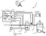
- FIG. 1illustrates a system in accordance with one embodiment of the invention.
- FIG. 2illustrates a method in accordance with one embodiment of the invention.
- embodiments of the invention described hereinmay be comprised of one or more conventional processors and unique stored program instructions that control the one or more processors to implement, in conjunction with certain non-processor circuits, some, most, or all of the functions of the system and method described herein.
- the non-processor circuitsmay include, but are not limited to, a radio receiver, a radio transmitter, signal drivers, clock circuits, power source circuits, and user input devices.
- FIG. 1illustrated therein is a system 10 for reducing energy consumption of an appliance 14 , such as, but not limited to, an air conditioning compressor, furnace, or heat pump.
- the systemincludes a control unit 12 having a current sense transformer 30 coupled thereto.
- the current sense transformer 30is suitable for coupling serially with a control wire 32 disposed between a control switch 34 and the appliance 14 .
- One suitable device for the control unit 12is a Digital Control Unit (DCU) box manufactured by Comverge, Inc.
- the DCU boxis designed to be coupled outside near the air conditioning compressor.
- the DCU boxmay additionally be employed for communication through various channels, including through wide area and local area networks to an energy provider.
- Another suitable devicewould be a thermostat manufactured by Comverge, Inc. Rather than being disposed on the outside of a building, the thermostat would be placed within the building.
- the control unit 12facilitates delivery of a certain number of watts of reduction assuming that the level of demand is available.
- the relevant conditions for providing that reductionare that the appliance 14 is operating at an energy rate significantly larger that the desired reduction in the predetermined time period, such as the previous hour, prior to curtailment, and that in the absence of curtailment the appliance would continue to operate at that level or a greater level of energy consumption.
- a detection module 36is disposed within the control unit 12 and is configured to detect from the current sense transformer 30 when the control wire 32 is active. For example, when a control switch, such as a thermostat 38 within a building, closes, the current sense transformer 30 detects that the thermostat 38 is activating the appliance 14 . The detection module 36 thus knows that the appliance 14 is “calling for” energy.
- the system 10implements load management by a reduction in energy, or the total kilowatt-hours called for within a given time frame. For example, the system 10 may curtail run time by a certain amount of energy called within a one-hour period.
- a processor 50is configured to determine a fractional run time by monitoring the detection module 36 . By integrating over a particular time period, such as one hour, when the appliance 14 is “calling” for energy, the processor 50 obtains an accurate estimate of the fraction of time during the particular time period that the appliance 14 is running.
- a memory 46coupled with the control unit 12 , includes a connected load value stored therein.
- a connected load valueis the quantity, value or rating in kilowatts of the appliance 14 .
- Such a connected load valuemay be either downloaded, wirelessly or otherwise, to the memory 46 .
- the control unit 12further comprises a local receiver 52 configured to receive the connected load value from a local source.
- the local receiver 52may be any of an infrared receiver, a radio frequency receiver, an optic receiver, a fiber optic receiver, or a wired receiver.
- the installer of the control unit 12may connect a handheld device (not shown) to the control unit 12 by way of the local receiver 52 upon installation to transmit the connected load value to the memory.
- the control unit installerhas several alternatives to obtain accurate estimates of the connected load value.
- One available methodologyis to actually measure the value.
- a current meter 15can be attached to one power lead 16 to the appliance 14 .
- the connected load valuein kilowatts can be measured.
- An alternative method for obtaining an estimate of the connected load valueis to examine data on the nameplate 18 of the appliance 14 .
- the nameplate 18 of some appliances 14such as air conditioning compressors, will include the rating in British Thermal Units per hour (BTU/hr), or in air conditioner tons.
- the nameplate 18may also include the SEER (seasonal energy efficiency rating).
- the BTU and SEER rating for most appliances 14 like air conditioning compressorscan be determined from commercially available databases by using the manufacturer's name and compressor model number.
- the connected load valuemay be stored to memory 46 in a variety of ways.
- one methodincludes the control unit 12 using a handheld device that communicates with a processor 50 disposed within the control unit 12 by infrared, radio frequency, or wired connection.
- the processor 50then stores the value in the memory 46 .
- the connected load valueis transmitted to the control unit 12 using radio frequency or power-line carrier communication medium from a remote source 20 .
- a receiver 48is coupled with the control unit and is configured to receive a power reduction factor from a remote source 20 , such as a utility or other energy provider.
- the receiver 48may be any of a radio frequency receiver, a power line carrier receiver, or other receiver.
- the power reduction factormay be received by radio frequency communication, as the receiver 48 in one embodiment comprises a wireless transceiver. Alternatively, power line carrier communications, or other means, may also be used.
- the message transmitted to the control unit 12contains the desired energy reduction, rather than a percentage curtailment time or a percentage of previous run time for curtailment and number of time based cycles of curtailment.
- the power reduction factor receivedmay comprise a power reduction profile.
- the power reduction profilemay include a series of power reduction factors, intended for implementation at various time intervals.
- One example of such a power reduction factormay be to reduce consumption by 1.0 kilowatt for the first hour, 1.5 kilowatts for the second hour, and 1.0 kilowatts for the third hour.
- the control unit 12Upon receipt of the desired power reduction factor, the control unit 12 , by way of the processor 50 , takes the fractional run time measured for the previous hour (or other applicable given time frame, with such “other applicable time frame” concept being intended throughout this description without being repeated) and multiplies that value times the stored connected load.
- This productis an estimate in kilowatt-hour of the “meter” energy consumed by the appliance 14 during the previous hour.
- the desired kilowatt reduction time one houris then subtracted from this value yielding the allowed energy consumption in each subsequent hour.
- the allowed energy consumption divided by the connected load valueis the allowed run time per hour. As a percentage this value may be rounded up to the nearest selected percentage and submitted.
- the processor 50is configured to calculate an allowed run time from the fractional run time and the power reduction factor.
- the processor 50may calculate the allowed run time from the fractional run time to curtail energy consumption as follows:
- Control unit 12by way of processor 50 , computes run time in previous hour with current sense transformer 30 measurement, and determines run time of 42 minutes.
- the processor 50is configured to actuate the switch 34 so as to permit the appliance 14 to be operational in accordance with the allowed run time, which is calculated from the fractional run time and the power reduction factor.
- the control unit 12thereby permits the appliance 14 to be operational in accordance with an allowed run time that corresponds to the maximum amount of energy allowed to be drawn by the appliance 14 in a given time period.
- the control unit 12is allowed to operate for a predetermined duty cycle.
- the predetermined duty cyclemay be set to a 50% duty cycle.
- the run time in the previous houris less than 10 minutes it is proposed that the duty cycle default to 50%.
- FIG. 2illustrated therein is one embodiment of a method for reducing power consumption in an appliance in accordance with the invention.
- the methodsets forth steps that may occur in executable software in conjunction with the system and control unit set forth above.
- an appliance actuation sensorone example of which is the current sense transformer, is provided.
- the appliance actuation sensoris configured to detect when the appliance is operational.
- the appliance actuation sensoris monitored for a predetermined monitoring period to detect a fractional run time.
- a predetermined monitoring timeis one hour.
- Another exampleis every five minutes for one hour.
- a power reduction factoris received from a remote source, such as a wireless transmitter.
- a remote sourcesuch as a wireless transmitter.
- the power reduction factormay be received by radio frequency or power line carrier.
- an allowed run timeis calculated from the fractional run time and the power reduction factor.
- the allowed run timemay be calculated by first multiplying the fractional run time with the connected load value, which is retrieved from a local memory.
- the allowed run timethen includes the step of reducing the power consumption value by a power reduction factor.
- the step of reducing the power consumption valuein one embodiment, then includes subtracting the power reduction factor from the power consumption value.
- the difference between the power reduction factor and the power consumption valueis then divided by the connected load value.
- the allowed run timeis then rounded by a predetermined percentage. Such a method is set forth in the example above.
- the applianceis permitted to be operational in accordance with the allowed run time.
- This stepmay include the steps of permitting the appliance to be operational for the allowed operating time and prohibiting the appliance from being operational for a difference between the predetermined monitoring time and the allowed operating time.
- the methodmay further include the step of setting the allowed run time to a default value.
Landscapes
- Engineering & Computer Science (AREA)
- Power Engineering (AREA)
- Physics & Mathematics (AREA)
- General Physics & Mathematics (AREA)
- Supply And Distribution Of Alternating Current (AREA)
- Remote Monitoring And Control Of Power-Distribution Networks (AREA)
- Air Conditioning Control Device (AREA)
Abstract
Description
- A/C Size=3.0 tons (from nameplate)
- SEER=10.0 (from nameplate)
- kilowatt size=3.0 ton*12,000 BTU/ton-hr/10.0*1000=3.6 kilowatt (load this value into the control unit12)
- Energy consumption in previous hour=3.6 Kilowatt-hour*42 minutes/60 minutes=2.52 Kilowatt-hour
Claims (19)
Priority Applications (1)
| Application Number | Priority Date | Filing Date | Title |
|---|---|---|---|
| US11/470,534US7606639B2 (en) | 2005-09-07 | 2006-09-06 | Local power consumption load control |
Applications Claiming Priority (2)
| Application Number | Priority Date | Filing Date | Title |
|---|---|---|---|
| US74180105P | 2005-09-07 | 2005-09-07 | |
| US11/470,534US7606639B2 (en) | 2005-09-07 | 2006-09-06 | Local power consumption load control |
Publications (2)
| Publication Number | Publication Date |
|---|---|
| US20070129850A1 US20070129850A1 (en) | 2007-06-07 |
| US7606639B2true US7606639B2 (en) | 2009-10-20 |
Family
ID=37836388
Family Applications (1)
| Application Number | Title | Priority Date | Filing Date |
|---|---|---|---|
| US11/470,534Active - Reinstated2027-06-01US7606639B2 (en) | 2005-09-07 | 2006-09-06 | Local power consumption load control |
Country Status (2)
| Country | Link |
|---|---|
| US (1) | US7606639B2 (en) |
| WO (1) | WO2007030470A2 (en) |
Cited By (28)
| Publication number | Priority date | Publication date | Assignee | Title |
|---|---|---|---|---|
| US20100070103A1 (en)* | 2008-09-15 | 2010-03-18 | Aclara Power-Line Systems Inc. | Method for load control using temporal measurements of energy for individual pieces of equipment |
| US20100133352A1 (en)* | 2007-04-13 | 2010-06-03 | Basic Device Limited | Radiators |
| US20100134051A1 (en)* | 2009-03-02 | 2010-06-03 | Adura Technologies, Inc. | Systems and methods for remotely controlling an electrical load |
| US20100187914A1 (en)* | 2009-01-26 | 2010-07-29 | Geneva Cleantech Inc. | Methods and apparatus for power factor correction and reduction of distortion in and noise in a power supply delivery network |
| US20100191388A1 (en)* | 2005-03-14 | 2010-07-29 | Huizenga Charles A | Wireless Network Control for Building Facilities |
| US7925384B2 (en) | 2008-06-02 | 2011-04-12 | Adura Technologies, Inc. | Location-based provisioning of wireless control systems |
| US20110172846A1 (en)* | 2006-07-11 | 2011-07-14 | Regen Energy Inc. | Method and apparatus for managing an energy consuming load |
| US20110172845A1 (en)* | 2006-07-11 | 2011-07-14 | Regen Energy Inc. | Method and apparatus for managing an energy consuming load |
| US20110187574A1 (en)* | 2009-08-05 | 2011-08-04 | Tyco Electronics Corporation | Remote controlled power consuming device and module |
| US20110209765A1 (en)* | 2010-03-01 | 2011-09-01 | Koorosh Mozayeny | Water flow regulation system |
| US20110213332A1 (en)* | 2010-03-01 | 2011-09-01 | Koorosh Mozayeny | Medication delivery system |
| US20110213510A1 (en)* | 2010-03-01 | 2011-09-01 | Koorosh Mozayeny | Smart power strip |
| US8275471B2 (en) | 2009-11-06 | 2012-09-25 | Adura Technologies, Inc. | Sensor interface for wireless control |
| US8285419B2 (en) | 2010-04-23 | 2012-10-09 | Emerson Electric Co. | Thermostat load reduction based on percentage change in energy price |
| US20120303987A1 (en)* | 2011-05-27 | 2012-11-29 | Electronics And Telecommunications Research Institute | Energy control apparatus and method using property of electronic device |
| US8364325B2 (en) | 2008-06-02 | 2013-01-29 | Adura Technologies, Inc. | Intelligence in distributed lighting control devices |
| US20130197921A1 (en)* | 2012-02-01 | 2013-08-01 | Cellnet Innovations, Inc. | Methods and Systems for Requesting Compliance With a Requirement Over a Network |
| US8674544B2 (en) | 2009-01-26 | 2014-03-18 | Geneva Cleantech, Inc. | Methods and apparatus for power factor correction and reduction of distortion in and noise in a power supply delivery network |
| US8738186B2 (en) | 2010-04-23 | 2014-05-27 | Emerson Electric Co. | Load reduction based on percentage change in energy price |
| US20140207299A1 (en)* | 2010-04-08 | 2014-07-24 | Energy Resource Management Corp. | Energy-saving measurement, adjustment and monetization system and method |
| US9031702B2 (en) | 2013-03-15 | 2015-05-12 | Hayward Industries, Inc. | Modular pool/spa control system |
| US20150252805A1 (en)* | 2012-10-01 | 2015-09-10 | Thermo King Corporation | Methods and systems to detect an operation condition of a compressor |
| US9192019B2 (en) | 2011-12-07 | 2015-11-17 | Abl Ip Holding Llc | System for and method of commissioning lighting devices |
| US20170213451A1 (en) | 2016-01-22 | 2017-07-27 | Hayward Industries, Inc. | Systems and Methods for Providing Network Connectivity and Remote Monitoring, Optimization, and Control of Pool/Spa Equipment |
| US10605474B2 (en) | 2015-07-30 | 2020-03-31 | Encycle Corporation | Smart thermostat orchestration |
| US10608432B2 (en) | 2018-03-30 | 2020-03-31 | Midea Group Co., Ltd. | Appliance power management system |
| US20200319621A1 (en) | 2016-01-22 | 2020-10-08 | Hayward Industries, Inc. | Systems and Methods for Providing Network Connectivity and Remote Monitoring, Optimization, and Control of Pool/Spa Equipment |
| US11268717B2 (en) | 2017-08-16 | 2022-03-08 | Carrier Corporation | Thermostat power monitoring, mitigation and alert |
Families Citing this family (14)
| Publication number | Priority date | Publication date | Assignee | Title |
|---|---|---|---|---|
| US8020777B2 (en)* | 2007-01-29 | 2011-09-20 | Lawrence Kates | System and method for budgeted zone heating and cooling |
| DE102007062058A1 (en)* | 2007-12-21 | 2009-06-25 | Robert Bosch Gmbh | Method and device for analyzing the energy consumption of a machine |
| US9542658B2 (en) | 2008-11-06 | 2017-01-10 | Silver Spring Networks, Inc. | System and method for identifying power usage issues |
| US8324859B2 (en) | 2008-12-15 | 2012-12-04 | Comverge, Inc. | Method and system for co-operative charging of electric vehicles |
| US8106627B1 (en) | 2008-12-15 | 2012-01-31 | Comverge, Inc. | Method and system for co-operative charging of electric vehicles |
| US8903553B1 (en) | 2009-05-01 | 2014-12-02 | Comverge, Inc. | Method and system for controlling unitary air conditioners for reducing peak loads |
| US8239068B1 (en) | 2009-06-26 | 2012-08-07 | Comverge, Inc. | Method and system for cooperative powering of unitary air conditioners |
| JP5803248B2 (en)* | 2011-05-06 | 2015-11-04 | ソニー株式会社 | Information processing apparatus, information processing method, and program |
| CN103064504B (en)* | 2013-01-28 | 2017-04-12 | 浪潮电子信息产业股份有限公司 | Method for energy conservation of main board of server |
| CN103147970A (en)* | 2013-04-09 | 2013-06-12 | 云南云成印务有限公司 | Wireless network centralized control energy saving system for air compressors |
| CN104123460B (en)* | 2014-07-22 | 2017-02-15 | 上海申瑞继保电气有限公司 | Method for calculating refrigeration air conditioning degree days of public building |
| US20180004171A1 (en) | 2016-06-30 | 2018-01-04 | Johnson Controls Technology Company | Hvac system using model predictive control with distributed low-level airside optimization and airside power consumption model |
| US11789415B2 (en) | 2016-06-30 | 2023-10-17 | Johnson Controls Tyco IP Holdings LLP | Building HVAC system with multi-level model predictive control |
| US11067955B2 (en) | 2016-06-30 | 2021-07-20 | Johnson Controls Technology Company | HVAC system using model predictive control with distributed low-level airside optimization |
Citations (49)
| Publication number | Priority date | Publication date | Assignee | Title |
|---|---|---|---|---|
| US4298935A (en) | 1979-10-05 | 1981-11-03 | Honeywell Information Systems Inc. | Interface circuit for coupling an automated maintenance system to a CPU |
| US4337401A (en) | 1981-01-23 | 1982-06-29 | Honeywell Inc. | Adaptive load shedding |
| US4347974A (en) | 1981-03-05 | 1982-09-07 | Honeywell, Inc. | Temperature control system with night setback programming as a function of temperature conditioning load |
| US4387763A (en) | 1981-09-14 | 1983-06-14 | Honeywell Inc. | Multistage thermostat using multirate integral action and exponential setpoint change |
| US4389577A (en) | 1982-04-14 | 1983-06-21 | Honeywell Inc. | Apparatus for power load-shedding with auxiliary commandable thermostat |
| US4413250A (en) | 1981-09-03 | 1983-11-01 | Beckman Instruments, Inc. | Digital communication system for remote instruments |
| US4435162A (en) | 1982-12-22 | 1984-03-06 | Schoenwald Justin P | Trigonometry visualizers and method of making same |
| US4616325A (en) | 1983-06-17 | 1986-10-07 | Johnson Service Company | Zone condition controller and method of using same |
| US4633217A (en) | 1984-06-04 | 1986-12-30 | Yamatake Honeywell | Communication apparatus |
| US4742475A (en) | 1984-06-19 | 1988-05-03 | Ibg International, Inc. | Environmental control system |
| US4753388A (en) | 1987-07-24 | 1988-06-28 | Robertshaw Controls Company | Duty-cycle controlling thermostat construction, system utilizing the same and method of making the same |
| US4776514A (en) | 1986-11-17 | 1988-10-11 | Honeywell Ltd. | Two wire line voltage thermostat |
| US4819180A (en) | 1987-02-13 | 1989-04-04 | Dencor Energy Cost Controls, Inc. | Variable-limit demand controller for metering electrical energy |
| US4889179A (en) | 1987-11-25 | 1989-12-26 | J. R. Microwave, Inc. | Two wire adaptive system for interconnecting a four wire thermostat and a four wire, heating/cooling system |
| US5133302A (en) | 1990-09-18 | 1992-07-28 | Nissan Motor Co., Ltd. | Electric motor fan control system for vehicle |
| US5289362A (en) | 1989-12-15 | 1994-02-22 | Johnson Service Company | Energy control system |
| US5598349A (en) | 1994-10-25 | 1997-01-28 | Honeywell Inc. | Responding to pricing signals from a power supplier using mixed add/shed and profile setback delta schemes |
| US5635896A (en) | 1993-12-27 | 1997-06-03 | Honeywell Inc. | Locally powered control system having a remote sensing unit with a two wire connection |
| US5644173A (en) | 1994-10-25 | 1997-07-01 | Elliason; Kurt L. | Real time and/shed load based on received tier pricing and direct load control with processors for each load |
| US5675503A (en) | 1994-04-19 | 1997-10-07 | Denver Energy Cost Controls, Inc. | Adaptive load cycler for controlled reduction of energy use |
| JPH09266630A (en)* | 1996-03-27 | 1997-10-07 | Chubu Electric Power Co Inc | Power suppression control device, air conditioner |
| US5761083A (en) | 1992-03-25 | 1998-06-02 | Brown, Jr.; Robert J. | Energy management and home automation system |
| US5816491A (en) | 1996-03-15 | 1998-10-06 | Arnold D. Berkeley | Method and apparatus for conserving peak load fuel consumption and for measuring and recording fuel consumption |
| US5926776A (en) | 1997-06-04 | 1999-07-20 | Gas Research Institute | Smart thermostat having a transceiver interface |
| US6108614A (en) | 1993-01-22 | 2000-08-22 | Diablo Research Corporation | System and method for serial communication between a central unit and a plurality of remote units |
| US6212894B1 (en) | 1996-03-29 | 2001-04-10 | Waterfurnace International Inc. | Microprocessor control for a heat pump water heater |
| US6254009B1 (en) | 1999-12-08 | 2001-07-03 | Carrier Corporation | Communicating thermostat |
| US6305611B1 (en) | 2000-06-15 | 2001-10-23 | Carrier Corporation | Setback tracking thermostat |
| US6307464B1 (en) | 1999-12-20 | 2001-10-23 | Texas Instruments Incorporated | Method and apparatus using phases for communication in thermostat circuit |
| US6320494B1 (en) | 2000-01-18 | 2001-11-20 | Honeywell International Inc. | Full duplex communication system with power transfer on one pair of conductors |
| US6385510B1 (en) | 1997-12-03 | 2002-05-07 | Klaus D. Hoog | HVAC remote monitoring system |
| US6449533B1 (en) | 2000-05-25 | 2002-09-10 | Emerson Electric Co. | Thermostat and method for controlling an HVAC system with remote temperature sensor |
| US6480803B1 (en) | 2000-12-22 | 2002-11-12 | Carrier Corporation | Load shedding thermostat |
| US6478084B1 (en) | 1998-04-24 | 2002-11-12 | Steven Winter Associates, Inc. | Energy saving thermostat with a variable deadband |
| US6574581B1 (en) | 1994-10-25 | 2003-06-03 | Honeywell International Inc. | Profile based method for deriving a temperature setpoint using a ‘delta’ based on cross-indexing a received price-point level signal |
| US6619555B2 (en) | 2002-02-13 | 2003-09-16 | Howard B. Rosen | Thermostat system communicating with a remote correspondent for receiving and displaying diverse information |
| US6622097B2 (en) | 2001-06-28 | 2003-09-16 | Robert R. Hunter | Method and apparatus for reading and controlling electric power consumption |
| JP2003262387A (en) | 2002-03-08 | 2003-09-19 | Hitachi Ltd | Air conditioner |
| US6622926B1 (en) | 2002-10-16 | 2003-09-23 | Emerson Electric Co. | Thermostat with air conditioning load management feature |
| US6634566B2 (en) | 2002-02-12 | 2003-10-21 | Carrier Corporation | Advanced setback reporting thermostat |
| US6643566B1 (en) | 1999-01-12 | 2003-11-04 | Powerdsine Ltd. | System for power delivery over data communication cabling infrastructure |
| US6643567B2 (en) | 2002-01-24 | 2003-11-04 | Carrier Corporation | Energy consumption estimation using real time pricing information |
| US6718213B1 (en) | 2000-06-19 | 2004-04-06 | Electric City Corporation | Variable base load energy management system and method |
| US6798341B1 (en) | 1998-05-18 | 2004-09-28 | Leviton Manufacturing Co., Inc. | Network based multiple sensor and control device with temperature sensing and control |
| US6822555B2 (en) | 1999-11-15 | 2004-11-23 | General Electric Company | Fire system implemented with power line communications |
| US20050188706A1 (en) | 2004-01-15 | 2005-09-01 | Koichi Tokushige | Air conditioner and power line communication system |
| US6956463B2 (en) | 2002-10-02 | 2005-10-18 | Carrier Corporation | Method and apparatus for providing both power and communication over two wires between multiple low voltage AC devices |
| US7062361B1 (en) | 2000-05-02 | 2006-06-13 | Mark E. Lane | Method and apparatus for controlling power consumption |
| US7130719B2 (en) | 2002-03-28 | 2006-10-31 | Robertshaw Controls Company | System and method of controlling an HVAC system |
Family Cites Families (2)
| Publication number | Priority date | Publication date | Assignee | Title |
|---|---|---|---|---|
| GB2301758A (en)* | 1995-06-03 | 1996-12-11 | Ibm | Icon driven data processing system |
| JP3448737B2 (en)* | 2000-05-25 | 2003-09-22 | 住友重機械工業株式会社 | Wafer chuck cooling plate and wafer chuck |
- 2006
- 2006-09-06USUS11/470,534patent/US7606639B2/enactiveActive - Reinstated
- 2006-09-06WOPCT/US2006/034597patent/WO2007030470A2/enactiveApplication Filing
Patent Citations (51)
| Publication number | Priority date | Publication date | Assignee | Title |
|---|---|---|---|---|
| US4298935A (en) | 1979-10-05 | 1981-11-03 | Honeywell Information Systems Inc. | Interface circuit for coupling an automated maintenance system to a CPU |
| US4337401A (en) | 1981-01-23 | 1982-06-29 | Honeywell Inc. | Adaptive load shedding |
| US4347974A (en) | 1981-03-05 | 1982-09-07 | Honeywell, Inc. | Temperature control system with night setback programming as a function of temperature conditioning load |
| US4413250A (en) | 1981-09-03 | 1983-11-01 | Beckman Instruments, Inc. | Digital communication system for remote instruments |
| US4387763A (en) | 1981-09-14 | 1983-06-14 | Honeywell Inc. | Multistage thermostat using multirate integral action and exponential setpoint change |
| US4389577A (en) | 1982-04-14 | 1983-06-21 | Honeywell Inc. | Apparatus for power load-shedding with auxiliary commandable thermostat |
| US4435162A (en) | 1982-12-22 | 1984-03-06 | Schoenwald Justin P | Trigonometry visualizers and method of making same |
| US4616325A (en) | 1983-06-17 | 1986-10-07 | Johnson Service Company | Zone condition controller and method of using same |
| US4633217A (en) | 1984-06-04 | 1986-12-30 | Yamatake Honeywell | Communication apparatus |
| US4742475A (en) | 1984-06-19 | 1988-05-03 | Ibg International, Inc. | Environmental control system |
| US4776514A (en) | 1986-11-17 | 1988-10-11 | Honeywell Ltd. | Two wire line voltage thermostat |
| US4819180A (en) | 1987-02-13 | 1989-04-04 | Dencor Energy Cost Controls, Inc. | Variable-limit demand controller for metering electrical energy |
| US4753388A (en) | 1987-07-24 | 1988-06-28 | Robertshaw Controls Company | Duty-cycle controlling thermostat construction, system utilizing the same and method of making the same |
| US4889179A (en) | 1987-11-25 | 1989-12-26 | J. R. Microwave, Inc. | Two wire adaptive system for interconnecting a four wire thermostat and a four wire, heating/cooling system |
| US5289362A (en) | 1989-12-15 | 1994-02-22 | Johnson Service Company | Energy control system |
| US5133302A (en) | 1990-09-18 | 1992-07-28 | Nissan Motor Co., Ltd. | Electric motor fan control system for vehicle |
| US5761083A (en) | 1992-03-25 | 1998-06-02 | Brown, Jr.; Robert J. | Energy management and home automation system |
| US6108614A (en) | 1993-01-22 | 2000-08-22 | Diablo Research Corporation | System and method for serial communication between a central unit and a plurality of remote units |
| US5635896A (en) | 1993-12-27 | 1997-06-03 | Honeywell Inc. | Locally powered control system having a remote sensing unit with a two wire connection |
| US5675503A (en) | 1994-04-19 | 1997-10-07 | Denver Energy Cost Controls, Inc. | Adaptive load cycler for controlled reduction of energy use |
| US5644173A (en) | 1994-10-25 | 1997-07-01 | Elliason; Kurt L. | Real time and/shed load based on received tier pricing and direct load control with processors for each load |
| US6574581B1 (en) | 1994-10-25 | 2003-06-03 | Honeywell International Inc. | Profile based method for deriving a temperature setpoint using a ‘delta’ based on cross-indexing a received price-point level signal |
| US20060036350A1 (en) | 1994-10-25 | 2006-02-16 | Bohrer Philip J | Profile based method for deriving a temperature setpoint using a 'delta' based on cross-indexing a received price-point level signal |
| US5598349A (en) | 1994-10-25 | 1997-01-28 | Honeywell Inc. | Responding to pricing signals from a power supplier using mixed add/shed and profile setback delta schemes |
| US20030187549A1 (en) | 1994-10-25 | 2003-10-02 | Honeywell Inc. | Profile based method for deriving a temperature setpoint using a 'delta' based on cross-indexing a received price-point level signal |
| US5816491A (en) | 1996-03-15 | 1998-10-06 | Arnold D. Berkeley | Method and apparatus for conserving peak load fuel consumption and for measuring and recording fuel consumption |
| JPH09266630A (en)* | 1996-03-27 | 1997-10-07 | Chubu Electric Power Co Inc | Power suppression control device, air conditioner |
| US6212894B1 (en) | 1996-03-29 | 2001-04-10 | Waterfurnace International Inc. | Microprocessor control for a heat pump water heater |
| US5926776A (en) | 1997-06-04 | 1999-07-20 | Gas Research Institute | Smart thermostat having a transceiver interface |
| US6385510B1 (en) | 1997-12-03 | 2002-05-07 | Klaus D. Hoog | HVAC remote monitoring system |
| US6478084B1 (en) | 1998-04-24 | 2002-11-12 | Steven Winter Associates, Inc. | Energy saving thermostat with a variable deadband |
| US6798341B1 (en) | 1998-05-18 | 2004-09-28 | Leviton Manufacturing Co., Inc. | Network based multiple sensor and control device with temperature sensing and control |
| US6643566B1 (en) | 1999-01-12 | 2003-11-04 | Powerdsine Ltd. | System for power delivery over data communication cabling infrastructure |
| US6822555B2 (en) | 1999-11-15 | 2004-11-23 | General Electric Company | Fire system implemented with power line communications |
| US6254009B1 (en) | 1999-12-08 | 2001-07-03 | Carrier Corporation | Communicating thermostat |
| US6307464B1 (en) | 1999-12-20 | 2001-10-23 | Texas Instruments Incorporated | Method and apparatus using phases for communication in thermostat circuit |
| US6320494B1 (en) | 2000-01-18 | 2001-11-20 | Honeywell International Inc. | Full duplex communication system with power transfer on one pair of conductors |
| US7062361B1 (en) | 2000-05-02 | 2006-06-13 | Mark E. Lane | Method and apparatus for controlling power consumption |
| US6449533B1 (en) | 2000-05-25 | 2002-09-10 | Emerson Electric Co. | Thermostat and method for controlling an HVAC system with remote temperature sensor |
| US6305611B1 (en) | 2000-06-15 | 2001-10-23 | Carrier Corporation | Setback tracking thermostat |
| US6718213B1 (en) | 2000-06-19 | 2004-04-06 | Electric City Corporation | Variable base load energy management system and method |
| US6480803B1 (en) | 2000-12-22 | 2002-11-12 | Carrier Corporation | Load shedding thermostat |
| US6622097B2 (en) | 2001-06-28 | 2003-09-16 | Robert R. Hunter | Method and apparatus for reading and controlling electric power consumption |
| US6643567B2 (en) | 2002-01-24 | 2003-11-04 | Carrier Corporation | Energy consumption estimation using real time pricing information |
| US6634566B2 (en) | 2002-02-12 | 2003-10-21 | Carrier Corporation | Advanced setback reporting thermostat |
| US6619555B2 (en) | 2002-02-13 | 2003-09-16 | Howard B. Rosen | Thermostat system communicating with a remote correspondent for receiving and displaying diverse information |
| JP2003262387A (en) | 2002-03-08 | 2003-09-19 | Hitachi Ltd | Air conditioner |
| US7130719B2 (en) | 2002-03-28 | 2006-10-31 | Robertshaw Controls Company | System and method of controlling an HVAC system |
| US6956463B2 (en) | 2002-10-02 | 2005-10-18 | Carrier Corporation | Method and apparatus for providing both power and communication over two wires between multiple low voltage AC devices |
| US6622926B1 (en) | 2002-10-16 | 2003-09-23 | Emerson Electric Co. | Thermostat with air conditioning load management feature |
| US20050188706A1 (en) | 2004-01-15 | 2005-09-01 | Koichi Tokushige | Air conditioner and power line communication system |
Cited By (64)
| Publication number | Priority date | Publication date | Assignee | Title |
|---|---|---|---|---|
| US20100191388A1 (en)* | 2005-03-14 | 2010-07-29 | Huizenga Charles A | Wireless Network Control for Building Facilities |
| US7884732B2 (en) | 2005-03-14 | 2011-02-08 | The Regents Of The University Of California | Wireless network control for building facilities |
| US8527109B2 (en) | 2006-07-11 | 2013-09-03 | Regen Energy Inc. | Method and apparatus for managing an energy consuming load |
| US9110647B2 (en) | 2006-07-11 | 2015-08-18 | Regen Energy Inc. | Method and apparatus for managing an energy consuming load |
| US9703339B2 (en) | 2006-07-11 | 2017-07-11 | Encycle Corporation | Method and apparatus for managing an energy consuming load |
| US8918223B2 (en) | 2006-07-11 | 2014-12-23 | Regen Energy Inc. | Apparatus for managing an energy consuming load |
| US10139877B2 (en) | 2006-07-11 | 2018-11-27 | Encycle Corporation | Method and apparatus for managing an energy consuming load |
| US20110172846A1 (en)* | 2006-07-11 | 2011-07-14 | Regen Energy Inc. | Method and apparatus for managing an energy consuming load |
| US20110172845A1 (en)* | 2006-07-11 | 2011-07-14 | Regen Energy Inc. | Method and apparatus for managing an energy consuming load |
| US8527108B2 (en) | 2006-07-11 | 2013-09-03 | Regen Energy Inc. | Method and apparatus for managing an energy consuming load |
| US20100133352A1 (en)* | 2007-04-13 | 2010-06-03 | Basic Device Limited | Radiators |
| US9022299B2 (en)* | 2007-04-13 | 2015-05-05 | Basic Device Limited | Radiators |
| US7925384B2 (en) | 2008-06-02 | 2011-04-12 | Adura Technologies, Inc. | Location-based provisioning of wireless control systems |
| US8364325B2 (en) | 2008-06-02 | 2013-01-29 | Adura Technologies, Inc. | Intelligence in distributed lighting control devices |
| US9664814B2 (en) | 2008-06-02 | 2017-05-30 | Abl Ip Holding Llc | Wireless sensor |
| US10139787B2 (en) | 2008-06-02 | 2018-11-27 | Abl Ip Holding Llc | Intelligence in distributed lighting control devices |
| US20100070103A1 (en)* | 2008-09-15 | 2010-03-18 | Aclara Power-Line Systems Inc. | Method for load control using temporal measurements of energy for individual pieces of equipment |
| US8433452B2 (en)* | 2008-09-15 | 2013-04-30 | Aclara Power-Line Systems, Inc. | Method for load control using temporal measurements of energy for individual pieces of equipment |
| US20100191487A1 (en)* | 2009-01-26 | 2010-07-29 | Geneva Clean Tech Inc. | Energy usage monitoring with remote display and automatic detection of appliance including graphical user interface |
| US8674544B2 (en) | 2009-01-26 | 2014-03-18 | Geneva Cleantech, Inc. | Methods and apparatus for power factor correction and reduction of distortion in and noise in a power supply delivery network |
| US8447541B2 (en) | 2009-01-26 | 2013-05-21 | Geneva Cleantech Inc. | Energy usage monitoring with remote display and automatic detection of appliance including graphical user interface |
| US8450878B2 (en) | 2009-01-26 | 2013-05-28 | Geneva Cleantech, Inc. | Methods and apparatus for power factor correction and reduction of distortion in and noise in a power supply delivery network |
| US20100187914A1 (en)* | 2009-01-26 | 2010-07-29 | Geneva Cleantech Inc. | Methods and apparatus for power factor correction and reduction of distortion in and noise in a power supply delivery network |
| US7839017B2 (en) | 2009-03-02 | 2010-11-23 | Adura Technologies, Inc. | Systems and methods for remotely controlling an electrical load |
| US20100134051A1 (en)* | 2009-03-02 | 2010-06-03 | Adura Technologies, Inc. | Systems and methods for remotely controlling an electrical load |
| US20110187574A1 (en)* | 2009-08-05 | 2011-08-04 | Tyco Electronics Corporation | Remote controlled power consuming device and module |
| US8755915B2 (en) | 2009-11-06 | 2014-06-17 | Abl Ip Holding Llc | Sensor interface for wireless control |
| US8854208B2 (en) | 2009-11-06 | 2014-10-07 | Abl Ip Holding Llc | Wireless sensor |
| US8275471B2 (en) | 2009-11-06 | 2012-09-25 | Adura Technologies, Inc. | Sensor interface for wireless control |
| US20130261834A1 (en)* | 2010-03-01 | 2013-10-03 | Koorosh Mozayeny | Smart power strip |
| US20110213332A1 (en)* | 2010-03-01 | 2011-09-01 | Koorosh Mozayeny | Medication delivery system |
| US20110209765A1 (en)* | 2010-03-01 | 2011-09-01 | Koorosh Mozayeny | Water flow regulation system |
| US12397112B2 (en) | 2010-03-01 | 2025-08-26 | Koorosh Mozayeny | Smart power strip |
| US20110213510A1 (en)* | 2010-03-01 | 2011-09-01 | Koorosh Mozayeny | Smart power strip |
| US20140207299A1 (en)* | 2010-04-08 | 2014-07-24 | Energy Resource Management Corp. | Energy-saving measurement, adjustment and monetization system and method |
| US8285419B2 (en) | 2010-04-23 | 2012-10-09 | Emerson Electric Co. | Thermostat load reduction based on percentage change in energy price |
| US9230291B2 (en) | 2010-04-23 | 2016-01-05 | Emerson Electric Co. | Load reduction based on percentage change in energy price |
| US8738186B2 (en) | 2010-04-23 | 2014-05-27 | Emerson Electric Co. | Load reduction based on percentage change in energy price |
| US20120303987A1 (en)* | 2011-05-27 | 2012-11-29 | Electronics And Telecommunications Research Institute | Energy control apparatus and method using property of electronic device |
| US10111308B2 (en) | 2011-12-07 | 2018-10-23 | Abl Ip Holding Llc | System for and method of commissioning lighting devices within a wireless network |
| US9192019B2 (en) | 2011-12-07 | 2015-11-17 | Abl Ip Holding Llc | System for and method of commissioning lighting devices |
| US9888548B2 (en) | 2011-12-07 | 2018-02-06 | Abl Ip Holding Llc | System for and method of commissioning lighting devices |
| US9118207B2 (en)* | 2012-02-01 | 2015-08-25 | Landis+Gyr Innovations, Inc. | Methods and systems for requesting compliance with a requirement over a network |
| US20130197921A1 (en)* | 2012-02-01 | 2013-08-01 | Cellnet Innovations, Inc. | Methods and Systems for Requesting Compliance With a Requirement Over a Network |
| US10598179B2 (en)* | 2012-10-01 | 2020-03-24 | Thermo King Corporation | Methods and systems to detect an operation condition of a compressor |
| US11300125B2 (en) | 2012-10-01 | 2022-04-12 | Thermo King Corporation | Methods and systems to detect an operation condition of a compressor |
| US20150252805A1 (en)* | 2012-10-01 | 2015-09-10 | Thermo King Corporation | Methods and systems to detect an operation condition of a compressor |
| US10976713B2 (en) | 2013-03-15 | 2021-04-13 | Hayward Industries, Inc. | Modular pool/spa control system |
| US9031702B2 (en) | 2013-03-15 | 2015-05-12 | Hayward Industries, Inc. | Modular pool/spa control system |
| US9285790B2 (en) | 2013-03-15 | 2016-03-15 | Hayward Industries, Inc. | Modular pool/spa control system |
| US11822300B2 (en) | 2013-03-15 | 2023-11-21 | Hayward Industries, Inc. | Modular pool/spa control system |
| US10605474B2 (en) | 2015-07-30 | 2020-03-31 | Encycle Corporation | Smart thermostat orchestration |
| US20200319621A1 (en) | 2016-01-22 | 2020-10-08 | Hayward Industries, Inc. | Systems and Methods for Providing Network Connectivity and Remote Monitoring, Optimization, and Control of Pool/Spa Equipment |
| US20170213451A1 (en) | 2016-01-22 | 2017-07-27 | Hayward Industries, Inc. | Systems and Methods for Providing Network Connectivity and Remote Monitoring, Optimization, and Control of Pool/Spa Equipment |
| US11000449B2 (en) | 2016-01-22 | 2021-05-11 | Hayward Industries, Inc. | Systems and methods for providing network connectivity and remote monitoring, optimization, and control of pool/spa equipment |
| US11096862B2 (en) | 2016-01-22 | 2021-08-24 | Hayward Industries, Inc. | Systems and methods for providing network connectivity and remote monitoring, optimization, and control of pool/spa equipment |
| US11122669B2 (en) | 2016-01-22 | 2021-09-14 | Hayward Industries, Inc. | Systems and methods for providing network connectivity and remote monitoring, optimization, and control of pool/spa equipment |
| US11129256B2 (en) | 2016-01-22 | 2021-09-21 | Hayward Industries, Inc. | Systems and methods for providing network connectivity and remote monitoring, optimization, and control of pool/spa equipment |
| US10363197B2 (en) | 2016-01-22 | 2019-07-30 | Hayward Industries, Inc. | Systems and methods for providing network connectivity and remote monitoring, optimization, and control of pool/spa equipment |
| US11720085B2 (en) | 2016-01-22 | 2023-08-08 | Hayward Industries, Inc. | Systems and methods for providing network connectivity and remote monitoring, optimization, and control of pool/spa equipment |
| US10272014B2 (en) | 2016-01-22 | 2019-04-30 | Hayward Industries, Inc. | Systems and methods for providing network connectivity and remote monitoring, optimization, and control of pool/spa equipment |
| US10219975B2 (en) | 2016-01-22 | 2019-03-05 | Hayward Industries, Inc. | Systems and methods for providing network connectivity and remote monitoring, optimization, and control of pool/spa equipment |
| US11268717B2 (en) | 2017-08-16 | 2022-03-08 | Carrier Corporation | Thermostat power monitoring, mitigation and alert |
| US10608432B2 (en) | 2018-03-30 | 2020-03-31 | Midea Group Co., Ltd. | Appliance power management system |
Also Published As
| Publication number | Publication date |
|---|---|
| WO2007030470A3 (en) | 2007-11-15 |
| US20070129850A1 (en) | 2007-06-07 |
| WO2007030470A2 (en) | 2007-03-15 |
Similar Documents
| Publication | Publication Date | Title |
|---|---|---|
| US7606639B2 (en) | Local power consumption load control | |
| US8307229B2 (en) | Method of measuring power consumption of electric appliance | |
| US8761944B2 (en) | Apparatus and method for determining load of energy consuming appliances within a premises | |
| US20200034939A1 (en) | Energy budget manager | |
| US8560133B2 (en) | Energy smart system | |
| US20120176252A1 (en) | Apparatus and Method for Determining Load of Energy Consuming Appliances Within a Premises | |
| US20140163746A1 (en) | Apparatus and Method for Determining Load of Energy Consuming Appliances Within a Premises | |
| EP2494736B1 (en) | Method of controlling network system | |
| EP2592788A1 (en) | Utility powered communication gateway | |
| US20100235008A1 (en) | System and method for determining carbon credits utilizing two-way devices that report power usage data | |
| US8718798B2 (en) | Gateway mirroring of metering data between zigbee networks | |
| WO2013157030A1 (en) | Power monitoring device and power monitoring system | |
| US20120204044A1 (en) | Method of controlling network system | |
| WO2014185014A1 (en) | Management apparatus, device management method, and management system | |
| CA2753809A1 (en) | Energy smart system | |
| JP6074843B2 (en) | controller | |
| JP5799250B2 (en) | Device control apparatus and device control method | |
| KR101619961B1 (en) | Method for controlling an electric appliance | |
| KR101668701B1 (en) | Method for controlling a device | |
| JP2004325195A (en) | Power display system | |
| KR101449084B1 (en) | Load management system in home | |
| AU2012201017A1 (en) | Energy budget manager | |
| US20110042469A1 (en) | Furnace and central cooling apparatus configured with powerline communication for energy management |
Legal Events
| Date | Code | Title | Description |
|---|---|---|---|
| AS | Assignment | Owner name:COMVERGE, INC., NEW JERSEY Free format text:ASSIGNMENT OF ASSIGNORS INTEREST;ASSIGNOR:MIYAJI, MR. WENDELL M.;REEL/FRAME:018212/0308 Effective date:20060906 | |
| AS | Assignment | Owner name:SILICON VALLEY BANK, CALIFORNIA Free format text:SECURITY AGREEMENT;ASSIGNOR:COMVERGE, INC.;REEL/FRAME:021805/0291 Effective date:20081107 | |
| AS | Assignment | Owner name:PARTNERS FOR GROWTH III, L.P., CALIFORNIA Free format text:SECURITY AGREEMENT;ASSIGNOR:COMVERGE, INC.;REEL/FRAME:025329/0577 Effective date:20101105 | |
| AS | Assignment | Owner name:GRACE BAY HOLDINGS II, LLC (AS SUCCESSOR-BY-ASSIGN Free format text:INTELLECTUAL PROPERTY SECURITY AGREEMENT;ASSIGNOR:COMVERGE, INC.;REEL/FRAME:027959/0286 Effective date:20120326 | |
| AS | Assignment | Owner name:PEAK HOLDING CORP., FLORIDA Free format text:INTELLECTUAL PROPERTY SECURITY AGREEMENT;ASSIGNOR:COMVERGE, INC.;REEL/FRAME:027968/0112 Effective date:20120326 | |
| AS | Assignment | Owner name:COMVERGE, INC., GEORGIA Free format text:RELEASE BY SECURED PARTY (2008 FILING);ASSIGNOR:SILICON VALLEY BANK;REEL/FRAME:029382/0627 Effective date:20121127 Owner name:HERCULES TECHNOLOGY II, L.P., AS COLLATERAL AGENT, Free format text:SECURITY AGREEMENT;ASSIGNOR:COMVERGE, INC.;REEL/FRAME:029382/0849 Effective date:20121127 | |
| AS | Assignment | Owner name:TRIANGLE CAPITAL CORPORATION, NORTH CAROLINA Free format text:SECURITY AGREEMENT;ASSIGNOR:COMVERGE, INC.;REEL/FRAME:029407/0981 Effective date:20121127 | |
| AS | Assignment | Owner name:COMVERGE, INC., GEORGIA Free format text:RELEASE BY SECURED PARTY;ASSIGNOR:HERCULES TECHNOLOGY II, L.P.;REEL/FRAME:030422/0550 Effective date:20130514 | |
| FPAY | Fee payment | Year of fee payment:4 | |
| SULP | Surcharge for late payment | ||
| AS | Assignment | Owner name:COMVERGE, INC., GEORGIA Free format text:RELEASE BY SECURED PARTY FOR SECURITY INTEREST PREVIOUSLY RECORDED AT REEL 025329 FRAME 0577;ASSIGNOR:GRACE BAY HOLDINGS II, LLC, AS SUCCESSOR-BY-ASSIGNMENT TO PARTNERS FOR GROWTH III, L.P.;REEL/FRAME:030954/0746 Effective date:20130802 Owner name:COMVERGE, INC., GEORGIA Free format text:RELEASE BY SECURED PARTY OF SECURITY INTEREST PREVIOUSLY RECORDED AT REEL 027959 FRAME 0286;ASSIGNOR:GRACE BAY HOLDINGS II, LLC, AS SUCCESSOR-BY-ASSIGNMENT TO PARTNERS FOR GROWTH III, L.P.;REEL/FRAME:030954/0839 Effective date:20130802 | |
| AS | Assignment | Owner name:COMVERGE, INC., GEORGIA Free format text:RELEASE OF SECURITY INTEREST BY SECURED PARTY AS PREVIOUSLY RECORDED AT REEL 027968 FRAME 0112;ASSIGNOR:PEAK HOLDING CORP.;REEL/FRAME:031016/0115 Effective date:20130812 | |
| REMI | Maintenance fee reminder mailed | ||
| AS | Assignment | Owner name:ITRON DISTRIBUTED ENERGY MANAGEMENT, INC., WASHING Free format text:MERGER AND CHANGE OF NAME;ASSIGNORS:ITRON DR/EE INC.;COMVERGE, INC.;REEL/FRAME:043618/0811 Effective date:20170601 | |
| LAPS | Lapse for failure to pay maintenance fees | Free format text:PATENT EXPIRED FOR FAILURE TO PAY MAINTENANCE FEES (ORIGINAL EVENT CODE: EXP.) | |
| FP | Lapsed due to failure to pay maintenance fee | Effective date:20171020 | |
| AS | Assignment | Owner name:WELLS FARGO BANK, NATIONAL ASSOCIATION, NORTH CAROLINA Free format text:SECURITY INTEREST;ASSIGNORS:ITRON, INC.;ITRON NETWORKED SOLUTIONS, INC.;REEL/FRAME:045017/0893 Effective date:20180105 Owner name:WELLS FARGO BANK, NATIONAL ASSOCIATION, NORTH CARO Free format text:SECURITY INTEREST;ASSIGNORS:ITRON, INC.;ITRON NETWORKED SOLUTIONS, INC.;REEL/FRAME:045017/0893 Effective date:20180105 | |
| AS | Assignment | Owner name:ITRON, INC., WASHINGTON Free format text:MERGER AND CHANGE OF NAME;ASSIGNORS:ITRON DISTRIBUTED ENERGY MANAGEMENT, INC.;ITRON, INC.;ITRON, INC.;REEL/FRAME:045230/0691 Effective date:20171003 | |
| PRDP | Patent reinstated due to the acceptance of a late maintenance fee | Effective date:20180417 | |
| FEPP | Fee payment procedure | Free format text:SURCHARGE, PETITION TO ACCEPT PYMT AFTER EXP, UNINTENTIONAL (ORIGINAL EVENT CODE: M1558) Free format text:PETITION RELATED TO MAINTENANCE FEES GRANTED (ORIGINAL EVENT CODE: PMFG) Free format text:PETITION RELATED TO MAINTENANCE FEES FILED (ORIGINAL EVENT CODE: PMFP) | |
| MAFP | Maintenance fee payment | Free format text:PAYMENT OF MAINTENANCE FEE, 8TH YEAR, LARGE ENTITY (ORIGINAL EVENT CODE: M1552) Year of fee payment:8 | |
| STCF | Information on status: patent grant | Free format text:PATENTED CASE | |
| MAFP | Maintenance fee payment | Free format text:PAYMENT OF MAINTENANCE FEE, 12TH YEAR, LARGE ENTITY (ORIGINAL EVENT CODE: M1553); ENTITY STATUS OF PATENT OWNER: LARGE ENTITY Year of fee payment:12 |