US7606608B2 - Optical sampling interface system for in-vivo measurement of tissue - Google Patents
Optical sampling interface system for in-vivo measurement of tissueDownload PDFInfo
- Publication number
- US7606608B2 US7606608B2US11/008,001US800104AUS7606608B2US 7606608 B2US7606608 B2US 7606608B2US 800104 AUS800104 AUS 800104AUS 7606608 B2US7606608 B2US 7606608B2
- Authority
- US
- United States
- Prior art keywords
- guide
- tissue
- sample
- probe
- optical
- Prior art date
- Legal status (The legal status is an assumption and is not a legal conclusion. Google has not performed a legal analysis and makes no representation as to the accuracy of the status listed.)
- Active, expires
Links
- 230000003287optical effectEffects0.000titleclaimsabstractdescription123
- 238000005070samplingMethods0.000titleabstractdescription75
- 238000012623in vivo measurementMethods0.000titledescription3
- 239000000523sampleSubstances0.000claimsabstractdescription449
- 238000005259measurementMethods0.000claimsabstractdescription142
- 230000000087stabilizing effectEffects0.000claimsdescription3
- 239000012530fluidSubstances0.000abstractdescription30
- 230000008878couplingEffects0.000abstractdescription28
- 238000010168coupling processMethods0.000abstractdescription28
- 238000005859coupling reactionMethods0.000abstractdescription28
- 230000033001locomotionEffects0.000abstractdescription16
- 230000005499meniscusEffects0.000abstractdescription14
- 230000015572biosynthetic processEffects0.000abstractdescription5
- 210000001519tissueAnatomy0.000description222
- 210000003491skinAnatomy0.000description73
- WQZGKKKJIJFFOK-GASJEMHNSA-NGlucoseNatural productsOC[C@H]1OC(O)[C@H](O)[C@@H](O)[C@@H]1OWQZGKKKJIJFFOK-GASJEMHNSA-N0.000description67
- 239000008103glucoseSubstances0.000description67
- 239000010410layerSubstances0.000description58
- 238000000034methodMethods0.000description42
- XLYOFNOQVPJJNP-UHFFFAOYSA-NwaterSubstancesOXLYOFNOQVPJJNP-UHFFFAOYSA-N0.000description35
- 210000004369bloodAnatomy0.000description32
- 239000008280bloodSubstances0.000description32
- 239000000835fiberSubstances0.000description28
- 239000012491analyteSubstances0.000description27
- 230000036571hydrationEffects0.000description23
- 238000006703hydration reactionMethods0.000description23
- 230000003595spectral effectEffects0.000description19
- 239000000463materialSubstances0.000description18
- 230000007246mechanismEffects0.000description18
- 230000008569processEffects0.000description17
- 238000012937correctionMethods0.000description16
- 210000000434stratum corneumAnatomy0.000description16
- 206010012601diabetes mellitusDiseases0.000description15
- 238000004891communicationMethods0.000description11
- 239000012790adhesive layerSubstances0.000description10
- 230000008901benefitEffects0.000description10
- 230000001965increasing effectEffects0.000description10
- 238000001228spectrumMethods0.000description10
- 210000004207dermisAnatomy0.000description9
- 238000001727in vivoMethods0.000description9
- 238000012544monitoring processMethods0.000description9
- 102000008186CollagenHuman genes0.000description8
- 108010035532CollagenProteins0.000description8
- 229920001436collagenPolymers0.000description8
- 239000000470constituentSubstances0.000description8
- 230000001276controlling effectEffects0.000description8
- 238000006073displacement reactionMethods0.000description8
- 238000007373indentationMethods0.000description8
- 239000000203mixtureSubstances0.000description8
- 230000000638stimulationEffects0.000description8
- 230000007613environmental effectEffects0.000description7
- 210000000245forearmAnatomy0.000description7
- 239000000126substanceSubstances0.000description7
- 238000004497NIR spectroscopyMethods0.000description6
- 238000004458analytical methodMethods0.000description6
- 230000004888barrier functionEffects0.000description6
- 210000004027cellAnatomy0.000description6
- 238000001514detection methodMethods0.000description6
- 210000002615epidermisAnatomy0.000description6
- 238000011067equilibrationMethods0.000description6
- 210000003722extracellular fluidAnatomy0.000description6
- 229910000530Gallium indium arsenideInorganic materials0.000description5
- KXNLCSXBJCPWGL-UHFFFAOYSA-N[Ga].[As].[In]Chemical compound[Ga].[As].[In]KXNLCSXBJCPWGL-UHFFFAOYSA-N0.000description5
- 238000010521absorption reactionMethods0.000description5
- 238000000862absorption spectrumMethods0.000description5
- 239000000853adhesiveSubstances0.000description5
- 230000001070adhesive effectEffects0.000description5
- 238000013459approachMethods0.000description5
- 230000009286beneficial effectEffects0.000description5
- 238000009792diffusion processMethods0.000description5
- 238000009826distributionMethods0.000description5
- 230000000694effectsEffects0.000description5
- 238000005516engineering processMethods0.000description5
- 238000001125extrusionMethods0.000description5
- 238000005286illuminationMethods0.000description5
- 210000004379membraneAnatomy0.000description5
- 239000012528membraneSubstances0.000description5
- 230000035515penetrationEffects0.000description5
- -1polytetrafluoroethylenePolymers0.000description5
- 238000012545processingMethods0.000description5
- 102000004169proteins and genesHuman genes0.000description5
- 108090000623proteins and genesProteins0.000description5
- 238000002604ultrasonographyMethods0.000description5
- 230000008859changeEffects0.000description4
- 230000007423decreaseEffects0.000description4
- 238000013461designMethods0.000description4
- 230000002500effect on skinEffects0.000description4
- 210000003128headAnatomy0.000description4
- 238000010438heat treatmentMethods0.000description4
- 230000003993interactionEffects0.000description4
- 230000000670limiting effectEffects0.000description4
- 238000004519manufacturing processMethods0.000description4
- 239000013307optical fiberSubstances0.000description4
- 238000013450outlier detectionMethods0.000description4
- 238000007781pre-processingMethods0.000description4
- 230000005855radiationEffects0.000description4
- 230000002829reductive effectEffects0.000description4
- 238000002835absorbanceMethods0.000description3
- 210000000577adipose tissueAnatomy0.000description3
- 230000036760body temperatureEffects0.000description3
- 210000000476body waterAnatomy0.000description3
- 210000000170cell membraneAnatomy0.000description3
- 230000004907fluxEffects0.000description3
- 230000006870functionEffects0.000description3
- 230000036541healthEffects0.000description3
- 230000007774longtermEffects0.000description3
- 231100000344non-irritatingToxicity0.000description3
- 231100000252nontoxicToxicity0.000description3
- 230000003000nontoxic effectEffects0.000description3
- 230000003204osmotic effectEffects0.000description3
- 239000002245particleSubstances0.000description3
- 230000010412perfusionEffects0.000description3
- 210000002381plasmaAnatomy0.000description3
- 238000011176poolingMethods0.000description3
- 239000012925reference materialSubstances0.000description3
- 239000002904solventSubstances0.000description3
- 238000004611spectroscopical analysisMethods0.000description3
- 230000003068static effectEffects0.000description3
- TXEYQDLBPFQVAA-UHFFFAOYSA-NtetrafluoromethaneChemical compoundFC(F)(F)FTXEYQDLBPFQVAA-UHFFFAOYSA-N0.000description3
- 238000012546transferMethods0.000description3
- 238000011282treatmentMethods0.000description3
- 229920002683GlycosaminoglycanPolymers0.000description2
- 229920000544Gore-TexPolymers0.000description2
- 241000282412HomoSpecies0.000description2
- 102000011782KeratinsHuman genes0.000description2
- 108010076876KeratinsProteins0.000description2
- 208000017442Retinal diseaseDiseases0.000description2
- 206010038923RetinopathyDiseases0.000description2
- 229920000995SpectralonPolymers0.000description2
- 230000002411adverseEffects0.000description2
- 229940061720alpha hydroxy acidDrugs0.000description2
- 150000001280alpha hydroxy acidsChemical class0.000description2
- 238000013528artificial neural networkMethods0.000description2
- 230000017531blood circulationEffects0.000description2
- 230000001413cellular effectEffects0.000description2
- UUAGAQFQZIEFAH-UHFFFAOYSA-NchlorotrifluoroethyleneChemical groupFC(F)=C(F)ClUUAGAQFQZIEFAH-UHFFFAOYSA-N0.000description2
- 230000004087circulationEffects0.000description2
- 150000001875compoundsChemical class0.000description2
- 238000001816coolingMethods0.000description2
- 230000001419dependent effectEffects0.000description2
- 230000010339dilationEffects0.000description2
- 201000010099diseaseDiseases0.000description2
- 208000037265diseases, disorders, signs and symptomsDiseases0.000description2
- 230000005284excitationEffects0.000description2
- 229920005570flexible polymerPolymers0.000description2
- 210000004247handAnatomy0.000description2
- 208000019622heart diseaseDiseases0.000description2
- 230000002209hydrophobic effectEffects0.000description2
- 230000002706hydrostatic effectEffects0.000description2
- 230000001976improved effectEffects0.000description2
- 238000002329infrared spectrumMethods0.000description2
- NOESYZHRGYRDHS-UHFFFAOYSA-NinsulinChemical compoundN1C(=O)C(NC(=O)C(CCC(N)=O)NC(=O)C(CCC(O)=O)NC(=O)C(C(C)C)NC(=O)C(NC(=O)CN)C(C)CC)CSSCC(C(NC(CO)C(=O)NC(CC(C)C)C(=O)NC(CC=2C=CC(O)=CC=2)C(=O)NC(CCC(N)=O)C(=O)NC(CC(C)C)C(=O)NC(CCC(O)=O)C(=O)NC(CC(N)=O)C(=O)NC(CC=2C=CC(O)=CC=2)C(=O)NC(CSSCC(NC(=O)C(C(C)C)NC(=O)C(CC(C)C)NC(=O)C(CC=2C=CC(O)=CC=2)NC(=O)C(CC(C)C)NC(=O)C(C)NC(=O)C(CCC(O)=O)NC(=O)C(C(C)C)NC(=O)C(CC(C)C)NC(=O)C(CC=2NC=NC=2)NC(=O)C(CO)NC(=O)CNC2=O)C(=O)NCC(=O)NC(CCC(O)=O)C(=O)NC(CCCNC(N)=N)C(=O)NCC(=O)NC(CC=3C=CC=CC=3)C(=O)NC(CC=3C=CC=CC=3)C(=O)NC(CC=3C=CC(O)=CC=3)C(=O)NC(C(C)O)C(=O)N3C(CCC3)C(=O)NC(CCCCN)C(=O)NC(C)C(O)=O)C(=O)NC(CC(N)=O)C(O)=O)=O)NC(=O)C(C(C)CC)NC(=O)C(CO)NC(=O)C(C(C)O)NC(=O)C1CSSCC2NC(=O)C(CC(C)C)NC(=O)C(NC(=O)C(CCC(N)=O)NC(=O)C(CC(N)=O)NC(=O)C(NC(=O)C(N)CC=1C=CC=CC=1)C(C)C)CC1=CN=CN1NOESYZHRGYRDHS-UHFFFAOYSA-N0.000description2
- 230000001788irregularEffects0.000description2
- 210000002510keratinocyteAnatomy0.000description2
- 201000001119neuropathyDiseases0.000description2
- 230000007823neuropathyEffects0.000description2
- 230000037311normal skinEffects0.000description2
- 238000010238partial least squares regressionMethods0.000description2
- 208000033808peripheral neuropathyDiseases0.000description2
- 230000009467reductionEffects0.000description2
- 230000004044responseEffects0.000description2
- 238000000926separation methodMethods0.000description2
- 210000002966serumAnatomy0.000description2
- 241000894007speciesSpecies0.000description2
- 238000012360testing methodMethods0.000description2
- 230000000699topical effectEffects0.000description2
- 230000036572transepidermal water lossEffects0.000description2
- 238000002834transmittanceMethods0.000description2
- 210000000707wristAnatomy0.000description2
- QTBSBXVTEAMEQO-UHFFFAOYSA-MAcetateChemical compoundCC([O-])=OQTBSBXVTEAMEQO-UHFFFAOYSA-M0.000description1
- 238000012935AveragingMethods0.000description1
- OKTJSMMVPCPJKN-UHFFFAOYSA-NCarbonChemical compound[C]OKTJSMMVPCPJKN-UHFFFAOYSA-N0.000description1
- 229920000298CellophanePolymers0.000description1
- 208000017667Chronic DiseaseDiseases0.000description1
- 241001340526Chrysoclista linneellaSpecies0.000description1
- 208000001380Diabetic KetoacidosisDiseases0.000description1
- 102000016942ElastinHuman genes0.000description1
- 108010014258ElastinProteins0.000description1
- 208000002705Glucose IntoleranceDiseases0.000description1
- 206010060378HyperinsulinaemiaDiseases0.000description1
- 206010020772HypertensionDiseases0.000description1
- 208000013016HypoglycemiaDiseases0.000description1
- 102000004877InsulinHuman genes0.000description1
- 108090001061InsulinProteins0.000description1
- 241000428199MustelinaeSpecies0.000description1
- 208000008589ObesityDiseases0.000description1
- 229920002063SorbothanePolymers0.000description1
- 208000006011StrokeDiseases0.000description1
- XSQUKJJJFZCRTK-UHFFFAOYSA-NUreaChemical compoundNC(N)=OXSQUKJJJFZCRTK-UHFFFAOYSA-N0.000description1
- 210000001015abdomenAnatomy0.000description1
- 230000003187abdominal effectEffects0.000description1
- 230000002159abnormal effectEffects0.000description1
- 239000006096absorbing agentSubstances0.000description1
- 238000009825accumulationMethods0.000description1
- 150000001298alcoholsChemical class0.000description1
- 230000004075alterationEffects0.000description1
- 238000002266amputationMethods0.000description1
- 230000000202analgesic effectEffects0.000description1
- 238000000149argon plasma sinteringMethods0.000description1
- 210000001367arteryAnatomy0.000description1
- 230000000712assemblyEffects0.000description1
- 238000000429assemblyMethods0.000description1
- 230000002238attenuated effectEffects0.000description1
- WQZGKKKJIJFFOK-VFUOTHLCSA-Nbeta-D-glucoseChemical compoundOC[C@H]1O[C@@H](O)[C@H](O)[C@@H](O)[C@@H]1OWQZGKKKJIJFFOK-VFUOTHLCSA-N0.000description1
- 230000004071biological effectEffects0.000description1
- 230000008033biological extinctionEffects0.000description1
- 230000036770blood supplyEffects0.000description1
- 210000004204blood vesselAnatomy0.000description1
- 210000001601blood-air barrierAnatomy0.000description1
- 238000004364calculation methodMethods0.000description1
- 239000004202carbamideSubstances0.000description1
- 229910052799carbonInorganic materials0.000description1
- 231100000357carcinogenToxicity0.000description1
- 239000003183carcinogenic agentSubstances0.000description1
- 210000003850cellular structureAnatomy0.000description1
- 238000005253claddingMethods0.000description1
- 239000013065commercial productSubstances0.000description1
- 230000000295complement effectEffects0.000description1
- 230000001143conditioned effectEffects0.000description1
- 210000002808connective tissueAnatomy0.000description1
- 239000000356contaminantSubstances0.000description1
- 230000036757core body temperatureEffects0.000description1
- 238000005336crackingMethods0.000description1
- 238000002790cross-validationMethods0.000description1
- 238000013480data collectionMethods0.000description1
- 230000034994deathEffects0.000description1
- 230000018044dehydrationEffects0.000description1
- 238000006297dehydration reactionMethods0.000description1
- 239000003599detergentSubstances0.000description1
- 230000001627detrimental effectEffects0.000description1
- 235000014113dietary fatty acidsNutrition0.000description1
- 229940079593drugDrugs0.000description1
- 239000003814drugSubstances0.000description1
- 210000000624ear auricleAnatomy0.000description1
- 230000002526effect on cardiovascular systemEffects0.000description1
- 229920002549elastinPolymers0.000description1
- 238000000840electrochemical analysisMethods0.000description1
- 230000005670electromagnetic radiationEffects0.000description1
- 238000011156evaluationMethods0.000description1
- 238000002474experimental methodMethods0.000description1
- 210000000744eyelidAnatomy0.000description1
- 239000003925fatSubstances0.000description1
- 239000000194fatty acidSubstances0.000description1
- 229930195729fatty acidNatural products0.000description1
- 150000004665fatty acidsChemical class0.000description1
- 239000010685fatty oilSubstances0.000description1
- 230000001605fetal effectEffects0.000description1
- 102000034240fibrous proteinsHuman genes0.000description1
- 108091005899fibrous proteinsProteins0.000description1
- 125000001153fluoro groupChemical groupF*0.000description1
- NBVXSUQYWXRMNV-UHFFFAOYSA-NfluoromethaneChemical compoundFCNBVXSUQYWXRMNV-UHFFFAOYSA-N0.000description1
- 238000009472formulationMethods0.000description1
- 230000002068genetic effectEffects0.000description1
- 208000024693gingival diseaseDiseases0.000description1
- 230000004153glucose metabolismEffects0.000description1
- 230000004190glucose uptakeEffects0.000description1
- 125000002791glucosyl groupChemical groupC1([C@H](O)[C@@H](O)[C@H](O)[C@H](O1)CO)*0.000description1
- 208000035474group of diseaseDiseases0.000description1
- 210000002216heartAnatomy0.000description1
- 230000003054hormonal effectEffects0.000description1
- 229940088597hormoneDrugs0.000description1
- 239000005556hormoneSubstances0.000description1
- 201000001421hyperglycemiaDiseases0.000description1
- 230000003451hyperinsulinaemic effectEffects0.000description1
- 201000008980hyperinsulinismDiseases0.000description1
- 230000002218hypoglycaemic effectEffects0.000description1
- 238000003384imaging methodMethods0.000description1
- 201000001881impotenceDiseases0.000description1
- 230000006872improvementEffects0.000description1
- 230000001939inductive effectEffects0.000description1
- 208000015181infectious diseaseDiseases0.000description1
- 238000003780insertionMethods0.000description1
- 230000037431insertionEffects0.000description1
- 238000009434installationMethods0.000description1
- 229940125396insulinDrugs0.000description1
- 230000002452interceptive effectEffects0.000description1
- 230000003834intracellular effectEffects0.000description1
- 210000002977intracellular fluidAnatomy0.000description1
- 230000001678irradiating effectEffects0.000description1
- 208000017169kidney diseaseDiseases0.000description1
- 238000002372labellingMethods0.000description1
- 238000002386leachingMethods0.000description1
- 210000002414legAnatomy0.000description1
- 150000002632lipidsChemical class0.000description1
- 210000004185liverAnatomy0.000description1
- 238000012423maintenanceMethods0.000description1
- 238000013178mathematical modelMethods0.000description1
- 235000012054mealsNutrition0.000description1
- 238000010297mechanical methods and processMethods0.000description1
- 210000002752melanocyteAnatomy0.000description1
- 210000000716merkel cellAnatomy0.000description1
- 229910052751metalInorganic materials0.000description1
- 239000002184metalSubstances0.000description1
- 150000002739metalsChemical class0.000description1
- 238000001690micro-dialysisMethods0.000description1
- 230000005012migrationEffects0.000description1
- 238000013508migrationMethods0.000description1
- 210000003205muscleAnatomy0.000description1
- 238000001320near-infrared absorption spectroscopyMethods0.000description1
- 210000005036nerveAnatomy0.000description1
- 230000007935neutral effectEffects0.000description1
- 230000035764nutritionEffects0.000description1
- 235000016709nutritionNutrition0.000description1
- 235000020824obesityNutrition0.000description1
- 230000008520organizationEffects0.000description1
- 238000012856packingMethods0.000description1
- 230000037361pathwayEffects0.000description1
- 230000000149penetrating effectEffects0.000description1
- 230000035699permeabilityEffects0.000description1
- 230000004962physiological conditionEffects0.000description1
- 230000035479physiological effects, processes and functionsEffects0.000description1
- 230000035790physiological processes and functionsEffects0.000description1
- 230000019612pigmentationEffects0.000description1
- 229920000642polymerPolymers0.000description1
- 229920001343polytetrafluoroethylenePolymers0.000description1
- 239000004810polytetrafluoroethyleneSubstances0.000description1
- 201000009104prediabetes syndromeDiseases0.000description1
- 238000002360preparation methodMethods0.000description1
- 238000000513principal component analysisMethods0.000description1
- 238000012628principal component regressionMethods0.000description1
- 230000001737promoting effectEffects0.000description1
- 238000000611regression analysisMethods0.000description1
- 230000001105regulatory effectEffects0.000description1
- 238000009877renderingMethods0.000description1
- 230000024042response to gravityEffects0.000description1
- 238000012552reviewMethods0.000description1
- 230000035945sensitivityEffects0.000description1
- 210000004872soft tissueAnatomy0.000description1
- 238000002798spectrophotometry methodMethods0.000description1
- 238000010183spectrum analysisMethods0.000description1
- 238000009987spinningMethods0.000description1
- 230000006641stabilisationEffects0.000description1
- 238000011105stabilizationMethods0.000description1
- 230000004936stimulating effectEffects0.000description1
- 238000003860storageMethods0.000description1
- 238000007920subcutaneous administrationMethods0.000description1
- 210000004003subcutaneous fatAnatomy0.000description1
- 239000000758substrateSubstances0.000description1
- 230000001629suppressionEffects0.000description1
- 230000035900sweatingEffects0.000description1
- 238000003786synthesis reactionMethods0.000description1
- 230000036962time dependentEffects0.000description1
- 231100000440toxicity profileToxicity0.000description1
- 210000000689upper legAnatomy0.000description1
- 230000000007visual effectEffects0.000description1
- 230000002618waking effectEffects0.000description1
- 238000010792warmingMethods0.000description1
- 230000037221weight managementEffects0.000description1
Images


Classifications
- G—PHYSICS
- G01—MEASURING; TESTING
- G01N—INVESTIGATING OR ANALYSING MATERIALS BY DETERMINING THEIR CHEMICAL OR PHYSICAL PROPERTIES
- G01N21/00—Investigating or analysing materials by the use of optical means, i.e. using sub-millimetre waves, infrared, visible or ultraviolet light
- G01N21/17—Systems in which incident light is modified in accordance with the properties of the material investigated
- G01N21/25—Colour; Spectral properties, i.e. comparison of effect of material on the light at two or more different wavelengths or wavelength bands
- G01N21/31—Investigating relative effect of material at wavelengths characteristic of specific elements or molecules, e.g. atomic absorption spectrometry
- G01N21/35—Investigating relative effect of material at wavelengths characteristic of specific elements or molecules, e.g. atomic absorption spectrometry using infrared light
- G01N21/359—Investigating relative effect of material at wavelengths characteristic of specific elements or molecules, e.g. atomic absorption spectrometry using infrared light using near infrared light
- A—HUMAN NECESSITIES
- A61—MEDICAL OR VETERINARY SCIENCE; HYGIENE
- A61B—DIAGNOSIS; SURGERY; IDENTIFICATION
- A61B5/00—Measuring for diagnostic purposes; Identification of persons
- A61B5/145—Measuring characteristics of blood in vivo, e.g. gas concentration or pH-value ; Measuring characteristics of body fluids or tissues, e.g. interstitial fluid or cerebral tissue
- A61B5/14532—Measuring characteristics of blood in vivo, e.g. gas concentration or pH-value ; Measuring characteristics of body fluids or tissues, e.g. interstitial fluid or cerebral tissue for measuring glucose, e.g. by tissue impedance measurement
- A—HUMAN NECESSITIES
- A61—MEDICAL OR VETERINARY SCIENCE; HYGIENE
- A61B—DIAGNOSIS; SURGERY; IDENTIFICATION
- A61B5/00—Measuring for diagnostic purposes; Identification of persons
- A61B5/145—Measuring characteristics of blood in vivo, e.g. gas concentration or pH-value ; Measuring characteristics of body fluids or tissues, e.g. interstitial fluid or cerebral tissue
- A61B5/1455—Measuring characteristics of blood in vivo, e.g. gas concentration or pH-value ; Measuring characteristics of body fluids or tissues, e.g. interstitial fluid or cerebral tissue using optical sensors, e.g. spectral photometrical oximeters
- A—HUMAN NECESSITIES
- A61—MEDICAL OR VETERINARY SCIENCE; HYGIENE
- A61B—DIAGNOSIS; SURGERY; IDENTIFICATION
- A61B5/00—Measuring for diagnostic purposes; Identification of persons
- A61B5/68—Arrangements of detecting, measuring or recording means, e.g. sensors, in relation to patient
- A61B5/6801—Arrangements of detecting, measuring or recording means, e.g. sensors, in relation to patient specially adapted to be attached to or worn on the body surface
- A61B5/683—Means for maintaining contact with the body
- A61B5/6832—Means for maintaining contact with the body using adhesives
- A61B5/6833—Adhesive patches
- A—HUMAN NECESSITIES
- A61—MEDICAL OR VETERINARY SCIENCE; HYGIENE
- A61B—DIAGNOSIS; SURGERY; IDENTIFICATION
- A61B5/00—Measuring for diagnostic purposes; Identification of persons
- A61B5/145—Measuring characteristics of blood in vivo, e.g. gas concentration or pH-value ; Measuring characteristics of body fluids or tissues, e.g. interstitial fluid or cerebral tissue
- A61B5/1495—Calibrating or testing of in-vivo probes
Definitions
- the inventionrelates to optical sampling of tissue in-vivo. More particularly, the invention relates to an optical sampling interface system that includes an optical probe placement guide, a means for stabilizing the sampled tissue, an optical coupler for repeatably sampling a tissue measurement site in-vivo, and/or a means for compensating for measurement bias.
- In-vivo measurement of tissue properties and analytes using optical based analyzersrequires that a tissue measurement region be positioned and coupled with respect to an optical interface or probe.
- the requirements of an optical sampling interface system for such placement and couplingdepends upon the nature of the tissue properties and analytes under consideration, the optical technology being applied, and the variability of the tissue with respect to the target analyte.
- the optical measurementis performed in a laboratory where the majority of the factors pertaining to the measurement are controlled or constrained.
- there are many demanding in-vivo applicationsthat cannot be performed in a laboratory setting, but yet require a high degree of optical sampling reproducibility. In one example, a relatively unskilled operator or user must perform the optical measurement.
- One such applicationis the noninvasive estimation of glucose concentration through near-infrared spectroscopy.
- the desired end resultbeing an optical measurement system that is used by the consumer in a variety of environments, the optical sampling requirements are stringent. This problem is further considered through a discussion of the target application, the structure of live skin, and the dynamic properties of live tissue.
- Diabetesis a chronic disease that results in abnormal production and use of insulin, a hormone that facilitates glucose uptake into cells. While a precise cause of diabetes is unknown, genetic factors, environmental factors, and obesity play roles. Diabetics have increased risk in three broad categories: cardiovascular heart disease, retinopathy, and neuropathy. Diabetics often have one or more of the following complications: heart disease and stroke, high blood pressure, kidney disease, neuropathy (nerve disease and amputations), retinopathy, diabetic ketoacidosis, skin conditions, gum disease, impotence, and fetal complications. Diabetes is a leading cause of death and disability worldwide. Moreover, diabetes is merely one among a group of disorders of glucose metabolism that also includes impaired glucose tolerance and hyperinsulinemia, which is also known as hypoglycemia.
- the prevalence of individuals with diabetesis increasing with time.
- the World Health Organization (WHO)estimates that diabetes currently afflicts 154 million people worldwide. There are 54 million people with diabetes living in developed countries. The WHO estimates that the number of people with diabetes will grow to 300 million by the year 2025. In the United States, 15.7 million people or 5.9 percent of the population are estimated to have diabetes. Within the United States, the prevalence of adults diagnosed with diabetes increased by 6% in 1999 and rose by 33% between 1990 and 1998. This corresponds to approximately eight hundred thousand new cases every year in America. The estimated total cost to the United States economy alone exceeds $90 billion per year. Diabetes Statistics , National Institutes of Health, Publication No. 98-3926, Bethesda, Md. (November 1997).
- near-infrared spectroscopyinvolves the illumination of a region of the body with near-infrared electromagnetic radiation, i.e. light in the wavelength range 700 to 2500 nm.
- the lightis partially absorbed and scattered, according to its interaction with the tissue constituents prior to being reflected back to a detector.
- the detected lightcontains quantitative information that is based on the known interaction of the incident light with components of the body tissue including water, fat, protein, and glucose.
- Previously reported methods for the noninvasive estimation of glucose concentration through near-infrared spectroscopyrely on the detection of the magnitude of light attenuation caused by the absorption signature of blood glucose as represented in the targeted tissue volume.
- the targeted tissue volumeis that portion of irradiated tissue from which light is reflected or transmitted to the spectrometer detection system.
- the signal due to the absorption of glucoseis extracted from the spectral measurement through various methods of signal processing and one or more mathematical models.
- the modelsare developed through the process of calibration on the basis of an exemplary set of spectral measurements and associated reference blood glucose concentrations (the calibration set) based on an analysis of capillary (fingertip) blood, venous blood, and/or alternative site fluids.
- the measurementis further complicated by the heterogeneity of the sample, the multi-layered structure of the skin, the rapid variation related to hydration levels, changes in the volume fraction of blood in the tissue, hormonal stimulation, temperature fluctuations, and changes in blood constituent concentrations. This is further considered through a discussion of the scattering properties of skin and the dynamic nature of the tissue.
- Skinincludes stratified layers, a cellular epidermis, and an underlying dermis of connective tissue. Below the dermis is a subcutaneous fatty layer or adipose tissue.
- the epidermisis the thin outer layer that provides a barrier to infection and loss of moisture, while the dermis is the thick inner layer that provides mechanical strength and elasticity.
- the epidermis layeris 10 to 150 ⁇ m thick and is divided into three layers, the basal, middle, and superficial layers. The basal layer borders the dermis and contains pigment-forming melanocyte cells, keratinocyte cells, Langherhan cells and Merkel cells See F.
- the stratum corneumthe outermost layer of the mammalian epidermis, is formed and continuously replenished by the slow upward migration of aqueous keratinocyte cells from the germinative basal layer of the epidermis. It is replenished about every two weeks in mature adults.
- This complex process involving intracellular dehydration and synthesis of an insoluble protein, keratinresults in keratin-filled, biologically inactive, shrunken cells.
- These flat, dehydrated, hexagonal cellsare tightly bound to their neighbors and each is approximately 30 ⁇ m wide and 0.8 ⁇ m deep. See H.
- the glycosaminoglycansplay a key role in regulating the assembly of collagen fibrils and tissue permeability to water and other molecules. See K. Trier, S. Olsen, T. Ammitzboll, Acta. Ophthalmol ., v. 69, pp. 304 to 306 (1990).
- Collagenis the most abundant protein in the human body. Elastin fibers are also plentiful though they constitute a smaller proportion of the bulk.
- the dermisalso contains other cellular constituents and has a very rich blood supply, though no vessels pass the dermo-epidermal junction. See Ebling, supra. The blood vessels nourish the skin and control body temperature. In humans, the thickness of the dermis ranges from 0.5 mm over the eyelid to 4 mm on the back and has an average thickness of approximately 1.2 mm over most of the body. See S. Wilson, V. Spence, Phys. Med. Biol . v. 33, pp. 894-897 (1988).
- the spectral characteristics of water, protein, fat, urea, and glucoseare all unique in the near-infrared from 1100 to 2500 nm.
- the 93 percent to 96 percent of the incident beam that enters the skinis attenuated due to absorption or scattering within any of the layers of the skin.
- a definition of diffuse reflectance or remittanceis that fraction of incident optical radiation that is returned from a turbid sample.
- Absorption by the various skin constituents mentioned aboveaccount for the spectral extinction of the beam within each layer.
- Scatteringis the primary process by which the beam is returned to the incident layer. Scattering results from differences in a medium's refractive index, corresponding to differences in the physical characteristics of the particles that make up the medium. The spatial distribution and intensity of scattered light depends upon the size and shape of the particles relative to the wavelength, and upon the difference in refractive index between the medium and the constituent particles.
- the scattering coefficient of biological tissuedepends on many uncontrollable factors, which include the concentration of interstitial water, the density of structural fibers, and the shapes and sizes of cellular structures. Scattering by collagen fibers is of major importance in determining the penetration of optical radiation within the dermis. See F. Bolin, L. Preuss, R. Taylor, R. Ference, Appl. Opt , v. 28, pp. 2297 to 2303 (1989).
- the greater the diffusing power of a mediumthe greater the absorption related to multiple internal reflections. Therefore, reflectance values measured on different sites on the same person, or from the same site on different people, can differ substantially even when the target absorber is present in the same concentration.
- tissue parameterssuch as gender, age, genetics, disease, and exogenous factors due to lifestyle differences.
- tissue parameterssuch as gender, age, genetics, disease, and exogenous factors due to lifestyle differences.
- skin thickness in humansis greater in males than females
- subcutaneous fat thicknessis greater in females.
- collagen densitythe packing of fibrils in the dermis, is higher in the forearms of males than females. See S. Schuster, M. Black, E. McVitie, Br. J. Dermatol, v. 93, pp. 639 to 643, (1975).
- Total body wateraccounts for over 60% of the weight of the average person and is distributed between two major compartments: the intracellular fluid (two-thirds of total body water) and the extracellular fluid (one-third of total body water). See A. Guyton, J. Hall, Textbook of Medical of Physiology, 9 th ed., Philadelphia, W.B. Saunders Company (1996).
- the extracellular fluidin turn, is divided into the interstitial fluid, which is extravascular, and the blood plasma, which is intravascular. Water permeable lipid membranes separate the compartments and water is transferred rapidly between them through the process of diffusion to equalize the concentrations of water and other analytes across the membrane.
- the net water flux from one compartment to anotherconstitutes the process of osmosis, and the amount of pressure required to prevent osmosis is termed the osmotic pressure.
- the fluid compartmentsUnder static physiological conditions the fluid compartments are at equilibrium. However, during a net fluid gain or loss as a result of water intake or loss, all compartments gain or lose water proportionally and maintain a constant relative volume.
- I OAD A ⁇ ⁇ d C d x ⁇ ( 1 )
- the cell membraneis relatively impermeable to most solutes but highly permeable to water, whenever there is a higher concentration of a solute on one side of the cell membrane, water diffuses across the membrane toward the region of higher solute concentration. Large osmotic pressures can develop across the cell membrane with relatively small changes in the concentration of solutes in the extracellular fluid. As a result, relatively small changes in concentration of impermeable solutes in the extracellular fluid, such as glucose, can cause tremendous changes in cell volume.
- Noninvasive measurement of tissue properties and analytes, such as blood glucose concentrationmay employ near-infrared (near-IR) spectroscopic methods.
- near-IRnear-infrared
- S. Malin, T. Ruchti, supradescribes a system for noninvasively estimating blood glucose concentrations in-vivo, using near-infrared spectral analysis.
- Such near-infrared spectroscopy-based methodsuse calibrations that are developed using repeated in-vivo optical samples of the same tissue volume. Repeatability of these successive measurements is needed to produce a usable calibration.
- the heterogeneous and dynamic nature of living human skinleads to sampling uncertainty in the in-vivo measurement. Sampling differences can arise due to variable chemical composition and light scattering properties in tissue. As an example: because glucose is not uniformly distributed in tissue, a variation in the volume of tissue sampled is likely to lead to a variation in the strength of the glucose signal, even though glucose concentration in the tissue or blood remains constant.
- Variation in the repeated placement of the optical probe used for sampling at the measuring surface sitecan lead to sampling errors in two separate ways.
- variations in the location of the probecan cause a different tissue volume to be sampled and, second, varying the amount of pressure applied by the probe on the tissue can alter the optical scattering by the tissue, thereby changing the sampled tissue volume.
- a change in optical samplingmay lead to a variation in the spectral signal for a target analyte, even though the concentration of the analyte in the blood or tissue remains unchanged.
- air gaps between the surface of the optical probe and the surface of the tissue being sampledgive rise to variable surface reflection.
- Variable surface reflectionleads to a variable light launch into the tissue that, in turn, gives rise to an increase in nonlinear nature of the spectral measurements. Certainly, a variable nonlinear measurement is difficult to calibrate.
- U.S. Pat. No. 5,956,150(Sep. 21, 1999) describes a method for using an illumination device, such as a laser to align two components during an assembly process.
- the Kanne teachingsare directed to a manufacturing process rather than optical sampling of tissue in-vivo.
- the Kanne devicedoes not provide any means for repeatably placing a probe guide at a tissue measurement site. It also lacks means for monitoring the surface temperature at a tissue measurement site and for minimizing surface temperature fluctuations and accumulation of moisture at a tissue measurement site.
- U.S. Pat. No. 5,448,662disclose an optical fiber support that is coupled to a frame for positioning an optical fiber at a desired angular position.
- Kittell et al.have nothing to do with optical sampling of tissue in-vivo.
- the disclosed deviceallows an operator to immobilize an optical fiber so that it is maintained in a fixed position, but it lacks means of repeatably coupling a fiber optic probe to a tissue measurement site. It also has lacks means for monitoring the surface temperature at a tissue measurement site and for minimizing accumulated moisture and temperature fluctuations at the site.
- a solution to the problem of controlling optical sampling during a noninvasive measurementmust address several challenges posed by the structural characteristics and dynamic properties of living tissue, such as:
- the inventionprovides an optical sampling interface system that minimizes sampling variation and/or state fluctuations at a measurement site, thereby allowing optical tissue sampling and subsequent noninvasive analyte concentration estimation with increased precision and accuracy.
- FIG. 1is a perspective view of a glucose tracking system analyzer according to the invention
- FIG. 2shows an optical probe placement guide according to the invention
- FIG. 3provides a sample probe placement guide that uses a magnet according to the invention
- FIG. 4shows a jig for sample probe registration that includes a rotational alignment control according to the invention
- FIG. 5illustrates a guide for alignment of a sample probe to a tissue site with an aperture partially within the perimeter of the guide according to the invention
- FIG. 6illustrates a guide for alignment of a sample probe to a tissue site with an aperture outside the perimeter of the guide according to the invention
- FIG. 7illustrates a guide with two registration points for control of at least rotational alignment according to the invention
- FIG. 8illustrates a guide for alignment of a sample probe to a tissue site with two separate alignment pieces according to the invention
- FIG. 9illustrates a guide using magnets for alignment of a sample probe to a tissue site with two separate alignment pieces according to the invention
- FIG. 10illustrates a guide with a layer between an alignment piece and a sample site according to the invention
- FIG. 11illustrates a guide with two layers between an alignment piece and a sample site according to the invention
- FIG. 12presents a guide with two layers between an alignment piece and a sample site interacting with a sample probe according to the invention
- FIG. 13illustrates a guide with at least one flexible part according to the invention.
- FIGS. 14 and 14 bpresent a guide allowing a z-axis movable sample probe according to the invention.
- the inventionprovides an optical sampling interface system, jig, or guide that eliminates or minimizes factors that account for sampling error.
- An optical probe placement guidefacilitates repeatable placement of an interfacing optic, such as an optical sample probe tip, with the surface of a tissue measurement site with a minimal degree of tissue distortion and displacement. Repeatable placement is also described as indexing a position or registering a position.
- the major structural component of a probe placement guideis a mechanical interface of one or more guide elements with one or more corresponding sections of the interfacing sample probe.
- the lock and key mechanism of the guide element(s) and the interfacing sample probeimproves the precision of probe placement during the course of multiple measurements.
- Different embodiments of the inventioninclude a guide comprising any of:
- An optional occlusive element placed over the tissue meniscusisolates the tissue meniscus from environmental fluctuations.
- the occlusive elementstabilizes and controls the temperature of the surface of the sample site and/or stabilizes the degree of hydration of the tissue meniscus and thereby stabilizes surface tension of the tissue meniscus.
- An optional coupling medium placed on the surface tissue at the tissue measurement siteeliminates sampling errors due to air gaps between the skin surface and the optical probe.
- An optional measurement and bias correction elementapplies a bias correction to spectral measurements, and the associated analyte measurement.
- Precision in sampling locationallows bias to be removed if a correction process, such as mean centering, is used in the algorithm. This is addressed in the preprocessing section below.
- bias correctionsare performed for example, with all data taken over the course of one guide placement or until another reference concentration is determined. When the guide is removed and replaced, a new bias correction is preferably determined for all subsequent data taken with the second guide placement.
- each of the separate elements of the invented systemcan be individually deployed as standalone solutions to counter various sources of measurement error.
- the probe placement guideindependent of the other elements of the system, provides a significant reduction in sampling error.
- the occlusive elementprovides a significant reduction in measurement error due to state fluctuations at the surface of the measurement site.
- the correction algorithmcan be applied to spectral measurements in settings lacking the other elements of the system.
- An analyte detection and/or concentration tracking systemis used, such as a glucose tracking system.
- a glucose concentration tracking systemuses a glucose concentration analyzer that comprises at least a source, a sample interface, at least one detector, and, a system for implementing an associated algorithm.
- an analyzer 10is separated into elements including a base module 11 , a communication bundle 12 , and a sample module 13 .
- the sample modulealso referred to as a sampling module, interfaces with a tissue sample and at the same or different times with one or more reference materials.
- the base module 11 , communication bundle 12 , sample module 13 , and system for implementing the algorithmare referred to as a spectrometer and/or analyzer 10 .
- the base module and sample moduleare in separate housings.
- Providing separate housings for the sample module and base modulehas multiple benefits, such as thermal, size, and weight management.
- the sample moduleis allowed to be smaller and weigh less without the bulk of the base module. This allows easier handling by the user and less of a physical impact on the sample site by the sample module.
- heat from a source in one housingis separated from a detector in a second housing, allowing for ease in cooling the detectors, thereby resulting in lower detector noise.
- sample modulebase module, and communication bundle are further described, infra.
- all of the components of a noninvasive glucose analyzerare included in a single unit, such as a professional use analyzer, a stand-alone analyzer, or a handheld analyzer.
- the sample moduleincludes a sensor head assembly that provides an interface between the glucose concentration tracking system and the patient.
- the tip of the sample probe of the sample moduleis brought into contact with the tissue sample.
- the tip of the sample probeis interfaced to a guide, such as an arm-mounted guide, to conduct data collection and removed when the process is complete.
- Guide accessoriesinclude an occlusion plug that is used to fill the guide cavity when the sensor head is not inserted in the guide, and/or to provide photo-stimulation for circulation enhancement.
- the following componentsare included in the sample module sensor head assembly: a light source, a single fiber optic, and coupling fluid.
- the sample moduleis in a separate housing from the base module.
- the sample moduleis integrated into a single unit with the base module, such as in a handheld or desktop analyzer.
- the communication bundleis wireless or is integrated into the analyzer,
- the communication bundleis a multi-purpose bundle.
- the multi-purpose bundlecomprises a flexible sheath that comprises at least one of:
- the analyzeris packaged with labeling instructions to train the user not to twist the bundle and, optionally, mechanical means to prevent the bundle from twisting more than one-quarter turn in either direction.
- a signalis communicated from the sample module to a base module.
- a portion of the diffusely reflected light from the siteis collected and transferred via at least one fiber-optic, free space optics, digitally after detection, or via an optical pathway to the base module.
- the base modulecontains a spectrograph.
- the spectrographseparates the spectral components of the diffusely reflected light, which are then directed to the photo-diode array (PDA).
- PDAphoto-diode array
- the PDAconverts the sampled light into a corresponding analog electrical signal, which is then conditioned by the analog front-end (AFE) circuitry.
- AFEanalog front-end
- the digital dataare then sent to the digital circuitry where they are checked for validity, processed, and stored in non-volatile memory.
- the processed resultsare recalled when the session is complete and, after additional processing, the individual glucose concentrations are available for display or transfer to a personal computer.
- the base modulealso, preferably, includes a central processing unit or equivalent for processors, memory, storage media for storing data, a model, a multivariate model, and/or analysis routines, such as those employing a model or net analyte signal.
- a systemis described herein that provides superior sampling precision of the target tissue volume through the use an optical probe placement guide or jig that is removably attached to the tissue site to achieve the goal of highly repeatable sample probe placement at a targeted tissue measurement site.
- a key characteristic of the guideis that it provides a means for registering the location of the targeted tissue volume with respect to the optical probe and/or tip of a sample module, such that a particular tissue volume is precisely sampled by the optical system. Registration refers to providing feedback regarding the position of the optical probe relative to a target location on the tissue.
- the means for registering between the guide and the optical probemay be mechanical, optical, electrical, and/or magnetic.
- some embodiments of the inventionallow for a more constant pressure/constant displacement to be applied to the sampling location which also enhances precision and accuracy of the glucose determination. While the guide greatly enhances positioning and allows associated data processing to be simpler and more robust, the guide is not an absolute requirement of the sampling module.
- an x, y, and z coordinate system relative to given a body partis used.
- the x-axisis along a body part, such as from an elbow to the wrist, from the shoulder to the elbow, or along the length of a digit of a hand.
- the y-axismoves across a body part.
- the x, y planetangentially touches the skin surface, such as at a sample site.
- the z-axisis normal to the x, y plane, such that an object moving toward the skin surface is moving along the z-axis.
- a sample probe brought toward a sample siteis moving along roughly the z-axis.
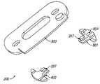
- a first embodiment of the inventioncomprises a guide 200 , having an aperture 202 , a mechanical stop 203 , and an optional temperature probe opening or slot 208 .
- a guide 200having an aperture 202 , a mechanical stop 203 , and an optional temperature probe opening or slot 208 .
- FIG. 2an example of the first embodiment of a guide 200 is provided.
- the guideat least partially surrounds an interfacing optic for the purpose of sampling in a precise location. Typically, this is done with an interface with defined points that interface part of the sample module, such as the sample probe in a lock and key fashion.
- the guide 200is provided in a number of shapes.
- An oval outer perimeter of a guideis shown in FIG. 2 .
- Additional shapes of the outer perimeterinclude a number of geometric shapes, such as rectangular, oval, circular, elongated, curved, or polygon.
- the outer edge of the guideis beveled to prevent snagging, such as by loose clothing or by an outside object, such as a tabletop or arm support.
- the outer edge of the guide on the outer surface, away from the sample siteis preferably rounded or beveled to reduce weight.
- the outer shape presented in FIG. 2approximates the surface of the sampled tissue site, for example, an oval guide is used with the volar or dorsal surface of the forearm.
- other shapesare used for other locations of the body such as the hand, the earlobe, the leg, the abdomen, the upper arm region, and the fingers.
- the guidecomprises an aperture into which the optical probe is received.
- the guidehas an aperture 202 , into which an optical probe is received.
- the sizes and shapes of the optical probe and the guide aperture 202are matched to each other such that when the optical probe is received by the guide, it fits snugly and provides a mechanical registration in the x-y plane relative to the tissue measurement site.
- the apertureserves several purposes including at least one of:
- the guide and the optical probeare equipped with mechanical stops 203 that limit and control the penetration of the optical probe into the tissue (the z-direction).
- the weight of the tissueis transferred to the optical probe through the mechanical stop 203 .
- the weightis preferably distributed across the guide, as opposed to being on the sample site surface, thereby reducing the pressure at the tissue measurement site.
- a flexible material or movable wings with some resistanceare used to cushion the weight or distribute the weight of the sample probe, respectively. Guides with flexible materials are further described, infra.
- the guideis, optionally, equipped with an opening 208 for the optional insertion of a temperature probe. This feature is particularly useful during the calibration phase for monitoring of skin temperature.
- the analyzer or sample modulecouples with a guide that is semi-permanently attached to the skin with a replaceable adhesive layer 201 .
- the adhesive layer 201resides between the inner surface of the guide 200 and the region about the sample site.
- the adhesive layeris applied to the guide at the time of manufacture.
- the adhesive layeris applied to the guide or tissue sample prior to usage.
- the adhesivecovers the entire inner surface of the guide, that surface of the guide that is in contact with the skin area adjacent to and surrounding the tissue measurement site.
- other attachment meansare suitable such as straps, suction, or armbands.
- the guideis attached to the tissue site at the beginning of a measurement period or some time before the beginning of a measurement period, infra.
- the guideis attached to the subject for a period of time, such as the waking hours of the subject. Typically, this period is the beginning of a particular day after a previously used guide has been removed.
- the guideis alternatively attached for a shorter time period or in a more permanent fashion, such as for a day, week, or month, especially in continuous monitoring glucose analyzers discussed below.
- the method of attachmentis to place the guide 200 onto a noninvasive measurement device with the adhesive layer in place and exposed.
- the tissue measurement siteis then placed onto the guide. During this first placement, the guide becomes affixed to the tissue site.
- the curvature of the guide surface contacting the tissue sampleis a shape correlating to the tissue.
- the inner surface or tissue side of the guideis preferably flat or nearly flat.
- the inner surface of the guidehas a curvature that complements the region of curvature about the sample, such as a radius of curvature of about 6, 4.5, 3, or 1.5 inches.
- the inner surface of the guidehas a curvature that complements the region of curvature about the sample, such as a radius of curvature of about 0.6, 0.4 or 0.2 inches.
- a guideis intended to allow for comfortable and unobtrusive use without application of significant mechanical energy to the sampled tissue site.
- the guide 200allows for the distribution of mechanical energy transferred from the instrument to the arm over a greater area around the measurement site.
- a guideis composed of a rigid polymer, allowing for the creation of a stable tissue meniscus.
- the guideis composed of a flexible material, such as a flexible polymer, that provides for a stabilization of the measurement site and deformation of the underlying tissue without applying undue force to the targeted tissue volume.
- a flexible materialsuch as SORBOTHANETM (Sorbothane Inc., Kent, Ohio), allows for reduced tissue distortions as the guide flexes on the surface of the sample rather than pushing into the sample.
- the guideis partially made of a rigid material and partially made of a flexible material, such as having rigid elements for alignment and flexible elements for distribution of applied forces from the sample probe.
- Other materials providing the requisite combination of rigidity and light weight, such as lightweight metals,are also suitable.
- a second embodiment of the inventionuses magnets to align a portion of a sample module to a sample site precisely and replaceably.
- magnets 207 placed into a guide 200 and a device coupled to the guideis provided.
- a plug 204is pictured that has magnets corresponding to the magnets of the guide.
- the sample module and/or one or more reference materialshave magnets that correspond to the guide magnets.
- Magnetsare used for at least one of:
- two magnetsare used, one on each side of the sampled site, to enhance alignment.
- One magnet coupled to a magnetizable material or a larger number of magnetsare alternatively used to provide the same effect.
- one or more magnetsare electrically activated to facilitate a controlled movement of the probe into the guide aperture and to allow, through reversal of the magnet poles, the probe to be withdrawn from the guide without pulling on the guide. It is recognized that there exist a large number of alternative mechanical methods for coupling two devices together, such as lock and key mechanisms, electro-magnets, machined fits, VELCRO, adhesives, snaps, and many other related techniques commonly known to those skilled in the art.
- a third embodimentprovides a cover in the aperture of a guide, such as a window, a longpass filter, or a bandpass filter.
- a windowsuch as an optical window, allows light to penetrate through the guide while still providing control of the surface of the sample site, such as occlusion and temperature control of the sample site.
- the aperturehouses a removable plug.
- the contact of a window or plug with the skinstabilizes the tissue by providing the same tissue displacement as the probe and increases the localized skin surface and shallow depth hydration.
- use of a contact windowallows a continuous barrier for proper hydration of the sampling site and a constant pressure interface.
- the use of a plug or contact windowleads to increased precision and accuracy in glucose determination by the removal of issues associated with dry or pocketed skin at the sampling site.
- a fourth embodimentuses a guide that controls rotational freedom of a sample probe relative to the sample site. Rotational freedom is controlled using means that orient the sample probe in a certain direction relative to the guide, such as mechanical, electrical, or magnetic means.
- a first half of a lock and key mechanismis on the guide and the corresponding half of a lock and key mechanism is on the sample probe.
- the guidecontains a mechanical extrusion, such as an isosceles triangle shaped post or a post or indentation with a single rotational degree of freedom, an indentation, or stop that limits the rotational orientation of the corresponding probe part.
- a magnetsuch as a rod
- a corresponding magnetsuch as a matching rod, is placed into the sample probe with a north and south pole in the opposite orientation.
- Controlling the x-, y-, and z-position of a partdoes not necessarily control the rotational position of a part.
- a topstays in the same x-, y, and z-position while spinning, yet the rotation varies.
- unlimited rotation C xis different from C N where N is an integer from 1 to less than infinity.
- controlling the rotation of the interfacing sample module or communication bundleis important and is not controlled by x-, y-, and z-positioning of the items relative to the guide.
- Controlling rotation of the sample probeis important for a number of reasons.
- photonsare not evenly distributed across a cross-section of the optical path in most optically-based instruments.
- hot spotsexist that have a larger photon flux compared to other regions of the cross-section.
- the incident photons from the source of a sample moduleare not evenly distributed without additional optics or great care and expense in alignment.
- a shadowis created that creates a cool spot in the cross sectional profile of the incident optics.
- rotation of the sample module interfacemoves the hot spot on the sampled tissue.
- an incident optic and/or a collection opticis often physically attached to an additional part.
- a source fiberis attached to a mount and a collection fiber is attached to a slit.
- Rotation of the sample modulecauses rotation of the optics, such as a fiber optic.
- rotationresults in micro-cracking of the core of the fiber or of the cladding about the fiber. This results in lost photons and an imprecise reading with rotation.
- interfacing opticsare not necessarily symmetrical. For example, a sampling probe comprised of an excitation fiber and a collection fiber is not symmetrical.
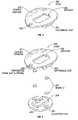
- FIG. 4an example of a guide 200 with a mechanical registration piece 401 is presented.
- the mechanical registration piece 401limits rotational freedom of the corresponding part of a sample probe to a single orientation.
- the tissue sample site 402is accessed through an aperture 202 that is contained within the guide.
- the x- and y-position of the sample probeis controlled relative to the guide and tissue sample site in an instance where the sample probe outer dimensions are tightly controlled to the aperture size.
- An additional benefit of controlling rotational freedomis that one or more of the x-, y-, and z-positions of the sample probe are set while aligning the rotational orientation of the sample probe relative to the guide. For example, a magnet flush with the surface aligns at least the z-position or a corresponding sample probe that also has a magnet flush with the surface.
- an extrusion from the guide or an indentation into the guidealign the corresponding indentation or extrusion of a sample probe in one or more of the x-, y-, and z-positions.
- the tissue sample site 402is, optionally, in a region that is sampled through an aperture in a guide, in a region that is outside of the contact area of the guide with the sample, or is in a region partially within the guide.
- FIG. 5an example of a polygonal guide 200 with a polygonal mechanical registration piece 401 is presented, where the sample site is partially overlapping with the generic shape of the guide.
- the corresponding sample probehas a tip that has a shape and or dimension that is different from the guide. At least the part of the sample probe that aligns to the registration piece 401 is complementary to the guide.
- a separate section of the sample probecontrols the incident and/or collection photons to a sample region 402 partially contained by the boundary of the guide.
- the mechanical registration piece in this examplecontrols the rotational orientation of the sample probe. In the instance where the registration piece is formed in three-dimensions and corresponds to a matching piece on the sample probe, the x-, y-, and z-position of the sample probe is also controlled versus the sample site.
- FIG. 6an example of a rectangular guide 200 with a magnetic registration piece 401 is presented where the sample site is outside of the region of the guide.
- the magnetic registration piecein this example controls the rotational orientation of the sample probe through the magnetic alignment of the poles, as described heretofore.
- a separate section of the sample probecontrols the incident and/or collection photons to a sample region 402 outside the perimeter of the guide footprint.
- the registration piececontrols the z-position of the sample probe relative to the sample site.
- a fifth embodiment of the inventionincludes a guide with at least two registration pieces.
- a guide 200is presented that has a first registration piece 701 and a second registration piece 702 .
- the two registration pieces on the guidecontrol at least one of the x-, y-, and z-position, as well as the rotational alignment of the corresponding sample probe.
- the first alignment piececontrols at least the x-position and y-position of the sample probe and the second alignment piece controls the z-position.
- the two alignment piecescontrol the rotational alignment of the sample probe.
- first registration piece and second registration pieceeach control one or more of the x-position, y-position, z-position, and rotational alignment of the sample probe.
- first and second registration piecescombined control any of the x-position, y-position, z-position, and rotational alignment of the corresponding sample probe.
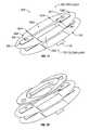
- a sixth embodiment of the inventionuses a guide comprising two or more separate pieces, where each piece is semi-permanently and replaceably attached to a region about the sample site.
- a guidecomprising a first alignment piece 801 and a second alignment piece 802 is presented.
- part of a housing of a sample probe 803is presented.
- the sample probeis of any design.
- the aperture of the housingcontains interfacing optics, such as illumination and collection optics.
- Optional magnets 207are provided.
- an example of an optional registration indentation 804is presented.
- the first alignment piece 801has registration points that control at least two of the x-, y-, and z-positions of the coupled sample probe.
- the first alignment piecehas a mechanical stop, such as a post.
- the sample probehas a corresponding mechanical stop, such as a post hole.
- the postsets into the post hole in a lock and key fashion.
- the x-, y-, and z-positions of the sample probeare hence registered to a fixed position relative to the first alignment piece.
- the first alignment pieceis one half of a lock and key mechanism, such as a ridge, that controls the x-, and z-position of the sample probe, which has the second half of a lock and key mechanism.
- the z-position of the sample probeis not controlled because the trough on the sample probe that corresponds to the ridge on the alignment piece has freedom of movement along the y-axis.
- a third exampleaddresses the instance where a single alignment lock mechanism with rotational symmetry, such as a post, still allows rotational freedom.
- the first alignment piecehas one-half of a lock and key mechanism that does not have rotational symmetry, such as an isosceles triangle indentation.
- the sample probehas a second half of the lock and key mechanism corresponding to that of the first alignment piece, such as an isosceles triangle extrusion that fits into the oval indentation.
- the x-, y-, and z-position and the rotational orientation of the sample probeare fixed relative to the sample site when aligned versus the first alignment piece.
- Additional registration meansinclude ball bearings, kinematic mounts, hinges, slides, extrusions, indentations, and mechanical stops.
- the second alignment piece 802has means for registering the sample probe in any of the ways described, supra, for the first alignment piece.
- the second alignment piececontrols at least one of the x-position, y-position, z-position, and rotational alignment of the corresponding sample probe.
- a benefit of using two alignment pieces for a guideis that the sample is not fixed in size and/or orientation with time.
- skinexpands and contracts due to physical responses to outside parameters, such as fluid intake, hydration, body temperature, and environmental temperature.
- a one piece guidecauses the skin to stretch, which results in a changed optical pathlength and sampled volume by probing photons.
- the skin layerssuch as the epidermal and dermal layers, get thinner. This results in more photons penetrating through to the fat layer.
- the spectral features observedchange, often with a loss of precision and/or accuracy of the corresponding glucose concentration estimations.
- the first alignment piecehas a post 804 that controls the x-, y-, and z-position of the corresponding sample probe.
- the second alignment pieceis a slide that controls the y-position and z-position of the corresponding sample probe.
- the sample probealigns to the post of the first alignment piece.
- the sample probealso aligns to the y-position and z-position of the second alignment piece.
- the second alignment pieceallows freedom of motion in the y-position.
- the first alignment piecealso controls the rotational freedom of the sample probe as described, supra.
- an aperture of the sample probecreates a meniscus about the sample site at time of sampling.
- the first alignment piececontains an optional magnet 901 that registers at least the x-, y-, and z-position of the sample probe.
- the second alignment piecealso contains an optional magnet 902 and is used to register at least the y- and z-position of the sample probe.
- the first and second alignment pieces 801 , 802are optionally attached directly to a tissue sample site or a region about the sample site, as described supra. In another instance, one or more intermediate layers are placed between the first and second alignment pieces 801 , 802 and the tissue sample.
- a first layer 1001is places on the sample side of the first and second alignment pieces 801 , 802 .
- the first layeris a material that covers at least part of the space between the alignment pieces and the tissue sample.
- first layers configurationsare provided.
- the first layer 1001is an adhesive, as described heretofore.
- part of the first layer 1001is composed of a flexible material 1002 , such as acetate.
- the flexible layerforms a living hinge, which helps to adapt the guide 200 to the changing shape of skin tissue and helps the guide 200 fit a curved surface.
- the living hingealso serves to distribute the weight of the guide and/or sample probe across a greater region of the skin tissue, especially as the sample probe is removed and replaced resulting in weight changes on or about the sample site.
- the weight of the sample probeis distributed by the guide off of the sample site that is optically probed.
- a separation section 1003 of the first layeris used to separate an adhesive layer from the sample probe, such as polytetrafluoroethylene.
- a first section 1002such as a flexible material section
- a second section 1003such as a separation section are both used in the first layer 1001 .
- the first and second sections 1002 , 1003are separated by a gap 1004 .
- the gapallows the first layer to expand, contract, twist, and/or deform as the skin tissue shape changes.
- the first layerserves at least one of several purposes.
- the first layer 1001covers at least a portion of the second layer 1101 , described infra, and protects the surface of the sample probe from the first layer.
- the first layer 1001is optionally separated into regions that are not attached by one or more small gaps 1004 allowing for fewer restraints on the skin tissue and hence fewer changes in the optical properties of the skin that affect optical based analyte concentration estimations.
- a second layer 1101is placed on the sample side of the first layer.
- the second layeris either replaceably attached or permanently attached to the first layer.
- the second layercontains one or more sublayers.
- a single sub-layeris used, such as an adhesive layer used to attach either the attachment pieces 801 , 802 or the first layer 1001 to the tissue sample.
- three sub-layersare used, such as a substrate layer sandwiched by an adhesive layer on either side.
- a third caseuses a peel-off layer on one or both sides of additional sub-layers for ease of attachment to any of the skin tissue, attachment pieces 801 , 802 , or first layer.
- a peel-off layer 1103is on the sample side of the second layer 1101 and the second layer contains at least an adhesive layer 1102 .
- An example of the guide presented in FIG. 11 interacting with a tip of a sample probeis illustrated in FIG. 12 .
- a particular embodimentuses a guide 200 that comprises at least a first and a second alignment piece 801 , 802 .
- a preferable embodimentalso includes a first layer 1001 and a second layer 1101 .
- a guide 200 that includes at least a first and a second alignment piece 801 , 802is available as a disposable item in a kit.
- the kitincludes one or both of a first layer 1001 and an adhesive layer 1101 .
- each of the two alignment piecescontains wings 1301 .
- the wingsare attached to the alignment pieces with a flexible material 1302 , such as a living hinge.
- the living hingecompensates for changes in at least one of shape, weight, and applied pressure.
- means for alignment of at least one of an x-position, y-position, z-position, and rotational positionare provided jointly by the two alignment pieces and/or separately be each of the alignment pieces.
- rotation of the sample probeis controlled by the guide while allowing z-axis movement of the guide.
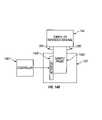
- the sample module 103includes a sample probe 1403 .
- a controller 1401controls an actuator 1402 that moves the sample probe 1403 .
- Signal processing meansresult in a control signal that is transferred from the controller 1401 to the sample probe 1403 typically through an actuator 1402 .
- the communicated control signalis used to control the z-axis movement of at least part of the sample module 103 relative to the tissue sample 104 or reference material.
- the part of the sample module movable along the z-axisis referred to as the sample probe or sampling probe 1403 .
- the controllersends the control signal from the algorithm to the sample module actuator, preferably via a communication bundle.
- the controller 1401receives input from the sample probe or other sensor and uses the input to move the actuator 1402 .
- the controlleris in different locations within the analyzer, such as in the sample module 103 or in the base module 101 .
- the actuator 1402subsequently moves the sample probe 1403 relative to the tissue sample site 104 .
- no controller or actuatoris used and the sample probe moves in response to gravity.
- the sample probe 1403is typically controlled along the z-axis from a position of no contact, to a position of tissue sample contact, and optionally to a position of tissue sample displacement.
- the sample probe 1403is presented in FIG. 14 at a first ( FIG. 14 a ) and second ( FIG. 14 b ) instant of time with the first time presenting the sample probe when it is not in contact with the sample site.
- the second timepresents the sample probe with minimal displacement of the sample tissue.
- the sample probeis, optionally, moved toward the sample, away from the sample, or remains static as a function of time as discussed, infra.
- An optional guideis attached to the sample and/or reference.
- Input to the controllerincludes a predetermined profile, an interpretation of spectral data collected from the sample probe, or input from a sensor, such as a pressure sensor, an optical sensor, or a thermal sensor.
- the guideprovides a means for optical registration.
- reflectors or light sensitive elementsare placed onto the guide.
- the optical probe assemblyis equipped with light sources and several detectors that allow the position of the guide to be accurately assessed, in either two or three dimensions. In a first configuration, two dimensions (x, y) are assessed and a mechanical stop is used to control the third dimension. In a second configuration, the location of the guide is optically assessed in all three dimensions (x, y, z). Because the position of the guide is constant with respect to the targeted tissue volume, the positional assessment provides accurate information regarding the location of the targeted tissue volume with respect to the optical probe. The registration information provided by such assessment is used to place the tissue site onto the optical probe, or vice versa, through any of the following means:
- the guidecontains any of a number of elements designed to enhance equilibration between the glucose concentration at the tissue sample site and a capillary site, such as the fingertip. Rapidly changing glucose concentrations as a function of time can lead to significant discrepancies between alternate site blood glucose concentration and traditional blood glucose concentrations, such as from a well perfused region such as finger. The concentration differences are directly related to diffusion and perfusion that combine to limit the rate of the equilibrium process. Equilibrium between the two sites allows for the use of glucose-related signal measured at an alternate site to be more accurate in estimation of finger blood glucose concentration.
- a number of elementsare, optionally, incorporated into the sample module and/or guide to increase sampling precision and to increase the net analyte signal for a glucose concentration estimation. These optional elements are preferably powered through the base module and communication bundle, but are alternatively battery operated. Equalization approaches include photonic stimulation, ultrasound pretreatment, mechanical stimulation, and heating and are described, infra. Notably, equilibration of the glucose concentration between the sampled site and a well-perfused region such as an artery or the capillary bed of the fingertip is not required. A minimization of the difference in glucose concentration between the two regions aids in subsequent glucose concentration determination.
- the guideoptionally contains one or more light emitting diodes (LEDs) that provide photonic stimulation at wavelengths that induce capillary blood vessel dilation.
- LEDslight emitting diodes
- Photostimulationis used to aid in equilibration of alternative site glucose concentrations with those of capillary blood.
- the preferred embodimentuses LEDs at about 890 nm in an array with control electronics set into the arm guide.
- Other example wavelengthsinclude about 910 nm, or at regions where water or another sample constituent strongly absorb.
- the LED'sare alternatively used in a continuous monitoring application where they are located in the probe sensing tip at the tissue interface. Due to the periods of excitation required for stimulation, the 890 nm LED is preferably powered by a rechargeable battery in the guide so that the LED may be powered when the communication bundle is not used.
- the guideoptionally contains an apparatus capable of delivering ultrasound energy into the sample site. Again, this technique is used to aid in equilibration of alternative site glucose concentrations with those of capillary blood by stimulating perfusion and/or blood flow.
- the guideoptionally contains an apparatus that provides mechanical stimulation of the sampled site prior to spectral data acquisition.
- an apparatusthat provides mechanical stimulation of the sampled site prior to spectral data acquisition.
- One exampleis a piezoelectric modulator than pulses in an out relative to the skin surface a distance of about 5 to 60 ⁇ m and preferably 20 to 50 ⁇ m in a continuous or duty cycle fashion.
- the guideoptionally contains a heating and/or cooling element, such as a strip heater or an energy transfer pad.
- Heatingis one mechanism of glucose compartment equilibration. These elements are used to match the core body temperature, to manipulate the local perfusion of blood, to avoid sweating and/or to modify the distribution of fluids among the various tissue compartments.
- the guide and/or plugcontains a heating element that warms the nominally cooler skin surface to approximately body temperature. Example temperatures are about 88, 90, 92, 94, 96, and 98 degrees Fahrenheit.
- sampling moduleis optionally brought into contact with the sample site without the use of a guide.
- a guide apertureis filled with a removable plug.
- the contact of a window or plug with the skinstabilizes the tissue by providing the same tissue displacement as the probe and increases the localized skin surface and shallow depth hydration.
- use of a contact windowallows a continuous barrier for proper hydration of the sampling site and a constant pressure interface.
- the use of a plug or contact windowleads to increased precision and accuracy in glucose determination by the removal of issues associated with dry or pocketed skin at the sampling site.
- an occlusion plug 204is normally inserted into the aperture 202 .
- the occlusion plugpenetrates into the aperture to the same extent as the optical probe and thereby creates a stable tissue state by simulating the contact energy of the optical probe.
- the occlusion plugis composed of a material that provides a hydration barrier, thus promoting the full and stable hydration of the stratum corneum.
- the plugis composed of the same material as the guide and possess a mechanical stop 205 to control the penetration into the tissue site.
- the size of the portion of the plug that is inserted into the aperture 206is matched to the portion of the optical probe that is received by the guide aperture 202 .
- Attachment of the plug to the guidemay be through the use of one or more magnets located in both the guide and plug assemblies 207 .
- other methods of attachmentmay be used, such as hook and loop, adhesives, and snaps.
- the plugcan be composed of a material that is elastic in nature and is kept in place by virtue of its tight fit into the guide aperture.
- the plugcan be a hydrophobic material, such as cellophane.
- an important aspect of the optical sampling systemis the maintenance of an optimal level of hydration of the surface tissue at the measurement site for enhancement of the optical signal, sample reproducibility, and suppression of surface reflectance.
- the preferred embodiment of the hydration mechanismis by occlusive blockage of trans-epidermal water loss. This blockage ensures a steady state hydration as water diffusing from interior tissue is trapped in the stratum corneum. Attainment of high hydration levels reduces the water concentration gradient that provides the driving force for this trans-epidermal water movement.
- the above described occlusive plugfits snugly into the guide aperture during periods between measurements, acting to insulate the tissue in the guide aperture from trans-epidermal water loss and the environmental effects of temperature and humidity that are known to influence the stratum corneum hydration state.
- wrapping a flexible polymer sheet (an occlusion patch) around the measurement sitemay also be used to attain a highly hydrated state via occlusion.
- the mechanisms for achieving stratum corneum hydrationmay also be used in coupled treatments.
- skin toner solution or an ultrasound energy applicationmay be used in conjunction with an occlusive plug.
- subsequent measurementsare made by placing the tissue site onto the noninvasive measurement device, after removing the occlusion plug and allowing the guide to provide mechanical registration. After the optical tissue measurement is performed, the tissue is taken away from the device and the occlusion plug is re-inserted.
- the guide apertureinduces the formation of a tissue meniscus, an upward bulge of tissue into the optical probe aperture.
- the hydrostatic pressure within the tissue in the apertureis greater than that on the nude (guideless) tissue sample. This increased hydrostatic pressure absorbs energy translated to the tissue when the probe contacts the tissue, thus limiting the resulting distortion of dermal collagen tissue. Distortion of dermal collagen has a strong effect on the tissue optical properties and thus the sampled tissue volume. To achieve this correction, the termination of the optical probe should be flush with the contact surface at the tissue measurement site when the optical probe is fully seated.
- the interface between the optical probe and the skin surface at the tissue measurement sitecan also be a significant source of sampling error. Because the underlying tissue is not homogenous, the surface skin at the tissue measurement site may be uneven, with frequent irregularities. Coupling the relatively smooth surface of the optical probe with the irregular skin surface leads to air gaps between the two surfaces. The air gaps create an interface between the two surfaces that adversely affects the measurement during optical sampling of tissue. An amount of a coupling medium such as a coupling fluid between the optical probe and the skin of the tissue measurement site or sample site eliminates such gaps.
- the coupling fluid:
- the active components of the coupling fluidfrom the class of compounds called perfluorocarbons, i.e. those containing only carbon and fluorine atoms. Nominally limiting chain length to less than twenty carbons provides for a molecule having the requisite viscosity characteristics.
- the molecular species contained in the perfluorocarbon coupling fluidmay contain branched or straight chain structures.
- a mixture of small perfluorocarbon molecules contained in the coupling fluid as polydisperse perfluorocarbonsprovides the required characteristics while keeping manufacturing costs low.
- the coupling fluidis a perfluoro compound, a fluorocarbon, a perfluorocarbon, or a narrowly defined group of fluorocarbons in terms of viscosity, such as those known as FC-40 and FC-70, manufactured by 3M Corporation (St. Paul, Minn.).
- FC-40 and FC-70manufactured by 3M Corporation (St. Paul, Minn.).
- FC-40 and FC-70manufactured by 3M Corporation (St. Paul, Minn.
- the sampling fluidbe formulated without the addition of other substances, such as alcohols or detergents, which may introduce artifacts into the optical sample.
- the exceptional stability of perfluoro compoundseliminates the environmental hazard commonly associated with chlorofluorocarbons.
- compositions containing perfluorocarbons and chlorofluorocarbonsare also suitable as coupling fluids.
- a blend of 90% polymeric chlorotrifluoroethylene and 10% other fluorocarbonshas the desired optical characteristics.
- Chlorotrifluoroethylenecould also be used. While these compositions have the desired optical characteristics, their toxicity profiles and their solvent characteristics render them less desirable than the previously described perfluoro compounds.
- fluid mediaare suitable for coupling of an optical probe to a tissue measurement site, for example, skin toner solutions or alpha hydroxy-acid solutions.
- a quantity of sampling fluidis placed at the interface of the tissue measurement site and the fiber optic probe so that the tissue measurement site and the fiber optic probe may be tightly coupled without leaving any air spaces between the two surfaces.
- one convenient way of placing the quantity of the sampling fluid at the interface between the tissue measurement site and the probeis to place a small amount of the fluid on the skin surface prior to placing the fiber optic probe, although it is easier to place it on the fiber-optic probe.
- non-fluid media having the requisite optical characteristic of being near-infrared neutralare also suitable as coupling media, for example, a GORE-TEX membrane interposed between the probe and the surface of the measurement site, particularly when used in conjunction with one of the fluid media previously described.
- bias correctionis preferably made to the measurement to account for variations in the size of the meniscus caused by the guide installation.
- a noninvasive measurement systemprovides a tissue measurement, m ⁇ 1 ⁇ N where N corresponds to the dimensionality of the measurement.
- mrefers to the intensity spectrum of the tissue sample represented by the intensity at N wavelengths, or wavelength ranges or selected wavelengths selected from a wavelength range, for example 700-2500 nm.
- a background or reference, m ois used to standardize or normalize the tissue measurement according to the calculation
- alog 10 ⁇ ⁇ m m o ⁇ ( 2 )
- m oan estimate of light incident on the sample
- man intensity spectrum of light detected
- ais analogous to an absorbance spectrum containing quantitative information that is based on the known interaction of the incident light with components of the body tissue.
- the tissue measurement, mcan be used directly instead of a.
- the standardized tissue measurement, ais preferably preprocessed to attenuate noise and to reduce the interference related to surface reflectance, tissue volume distortion, and instrumental effects to produce the processed tissue measurement, x.
- the preprocessing stepsinclude calculating the first derivative, selecting specific wavelengths and wavelength regions specific to the analyte of interest, and performing scatter correction or multiplicative scatter correction.
- the tissue templateis determined through one or more tissue measurements (after preprocessing) and a data selection criterion for example by selecting only tissue measurements that resemble each other closely and averaging them.
- the reference analyte valuesare determined from an electrochemical analysis of blood draws.
- g: M ⁇ 1is a calibration model used to map z to an estimate of the target analyte.
- the modelis determined from a calibration set of exemplary paired data points, each consisting of a pre-processed and bias corrected tissue measurement (z) and an associated reference analyte value (y) determined from an analysis of a blood or interstitial fluid sample.
- blood, serum, plasma, or interstitial drawsare taken from a tissue site that is either near the sensor sample site or has been designed/determined to reflect the sample site.
- tissue sitethat is either near the sensor sample site or has been designed/determined to reflect the sample site.
- non-invasive near-infrared measurements for the purpose of glucose measurementare taken for calibration on the forearm, it is possible in some individuals to collect a capillary blood draw from the same forearm or an alternate site such as opposite forearm.
- the method for designing the structure of gis through the process of system identification [L. Ljung, Systems Identification: Theory for the User, 2d.ed., Prentice Hall (1999)].
- the model parametersare calculated using known methods including multivariate regression or weighted multivariate regression [N. Draper, H. Smith, Applied Regression Analysis, 2d. ed., John Wiley and Sons, New York (1981)], principal component regression [H. Martens, T. Naes, Multivariate Calibration , John Wiley and Sons, New York (1989)], partial least squares regression [P. Geladi, B. Kowalski, Partial least - squares regression: a tutorial , Analytica Chimica Acta, 185, pp. 1-17, (1986)], or artificial neural networks [S. Haykin, Neural Networks: A Comprehensive Foundation , Prentice Hall, Upper Saddle River N.J. (1994)]. Calibration data must also be bias corrected if data contains subsets associated with different guide placement events.
- the bias corrected tissue measurementsundergo an outlier detection step.
- the necessity for outlier detection and the form of an outlier detection procedureare dependent on the sampling technology employed.
- Outlier detectionprovides a method of detecting invalid measurements through spectral variations that result from problems in the instrument, poor sampling of the subject or a subject outside the calibration set.
- One method of detecting outliersis through a principal component analysis and an analysis of the residuals.
- the instrumentcollected intensity spectra in diffuse reflectance from the forearm in the wavelength range 1050-2450 nm.
- the spectral sampling intervalwas 1 nm and the signal-to-noise ratio at the peak intensity was approximately 90 dB.
- the detectors used in the studywere a combination of Indium-Gallium-Arsenide (InGaAs) and extended InGaAs detectors.
- the optical configurationconsisted of a simple fiber-optic interface to the skin with a small ( ⁇ 2 mm) distance between the illumination and detection fibers.
- 60 measurementswere performed on a single subject.
- 60 sampleswere collected using the guide positioning system without occlusion and absorbance was calculated as previously described.
- 60 sampleswere collected with the use of both the guide positioning system and the preferred method of occlusion, i.e. a plug in the guide aperture.
- the decrease in surface variation associated with the water bandsdemonstrated the improved optical sampling realized as a result of the method of occlusion.
- the invented optical probe placement guideallows highly repeatable probe placement at a targeted tissue measurement site
- the inventionmay also be used to produce small sampling variations in a controlled manner by shifting the placement of the optical probe in known increments across successive optical samples.
- the inventionprovides a means of limiting sampling errors during in-vivo spectroscopic examination of tissue samples by providing highly repeatable optical probe placement at a targeted tissue measurement site.
- Structural features of the inventionminimize temperature fluctuations and variable stratum corneum hydration at the tissue measurement site.
- structural features of the inventionminimize variations in optical probe placement and variations due to tissue distortion and displacement. These minimizations each reduce sampling error.
- An optional temperature probe in direct contact with the skin surface at the tissue measurement siteallows the monitoring of skin temperature across successive measurements.
- An optical coupling fluideliminates air spaces at the interface of the skin surface of the tissue measurement site and the optical probe. A fully hydrated stratum corneum is attained by the use of an occlusive plug or other mechanism.
- spectral measurements, and resulting analyte measurementsare bias corrected to compensate error resulting from guide placement.
- optical sampling interface systemhas been herein described in relation to optical sampling of tissue, one skilled in the art will appreciate that the invention may be applied in other settings requiring repeatable placement of an optical probe.
- each of the elements of the optical probe placement guide measurement system herein describedare individually beneficial to the measurement and therefore can be used with or without the other elements.
- the guide, the hydration control system, the coupling fluid, and the bias correctionare uniquely beneficial.
- the hydration control process, bias correction, and the coupling fluidare still beneficial.
Landscapes
- Health & Medical Sciences (AREA)
- Life Sciences & Earth Sciences (AREA)
- Physics & Mathematics (AREA)
- General Health & Medical Sciences (AREA)
- Pathology (AREA)
- Surgery (AREA)
- Spectroscopy & Molecular Physics (AREA)
- Veterinary Medicine (AREA)
- Public Health (AREA)
- Animal Behavior & Ethology (AREA)
- Molecular Biology (AREA)
- Medical Informatics (AREA)
- Biophysics (AREA)
- Engineering & Computer Science (AREA)
- Biomedical Technology (AREA)
- Heart & Thoracic Surgery (AREA)
- Optics & Photonics (AREA)
- Chemical & Material Sciences (AREA)
- Biochemistry (AREA)
- Immunology (AREA)
- General Physics & Mathematics (AREA)
- Analytical Chemistry (AREA)
- Emergency Medicine (AREA)
- Measurement Of The Respiration, Hearing Ability, Form, And Blood Characteristics Of Living Organisms (AREA)
Abstract
Description
- Controlling surface reflection due to optical aberrations in surface coupling and stretching of the surface tissue;
- Controlling variations in tissue volume sampled due to imprecise placement;
- Controlling variable stretching of dermal collagen, leading to sampling volume uncertainty;
- Correcting measurement bias related to water pooling in the tissue resulting from pressure on the area in the vicinity of the measurement site from instrumentation or placement guides; and
- Stabilizing hydration of surface tissue.
- A placement guide for an optical probe that couples the probe to a tissue measurement site for in-vivo optical sampling of the tissue in a fashion allowing increased precision and accuracy of noninvasive analyte concentration estimations;
- A means of assuring that the same tissue sample volume is repeatably sampled, thus eliminating sampling errors due to mechanical tissue distortion and probe placement;
- A way to minimize temperature fluctuations and stabilize stratum corneum moisture content at the tissue measurement site, thus eliminating further sources of sampling error;
- An optical coupling medium to provide a constant interface between an optical probe and the skin at a tissue measurement site that is non-toxic and non-irritating and that does not introduce error into spectroscopic measurements;
- A means of monitoring surface temperature at the tissue measurement site, therefore assuring that the temperature remains constant across repeated optical samples; and
- A means for correcting the tissue sampling bias that results from the uncertainty inherent to the mechanical attachment process used to install the placement guide at the measurement site.
- A single part of the guide that controls the sample probe position relative to the tissue sample site for any of:
- an x-position;
- a y-position;
- a z-position; and
- a rotational position;
- At least one section of the guide that is flexible; and
- At least two separate parts of the guide wherein the two elements control alignment of the sample probe relative to a tissue sample site.
- A single part of the guide that controls the sample probe position relative to the tissue sample site for any of:
- Induces the formation of a tissue meniscus, created by the pooling of epidermal water in the guide aperture due to the relative difference in the contact pressure at the guide adhesion surface and the guide aperture, where no part of the guide contacts the tissue;
- Minimizes interference due to surface irregularities and controls variation in the volume of tissue sampled;
- Uses a two-part guide system;
- Uses a guide that controls rotation of a sample probe and allows z-axis movement of the probe;
- Uses a separate base module and sample module in conjunction with a guide;
- Uses a guide that controls rotation;
- Uses a guide with at least one flexible part; and
- Uses a guide of two or more layers.
- Electrical wires to supply operating power to the lamp in the light source;
- Thermistor wires;
- One or more fiber-optics, which direct diffusely reflected near-infrared light to the spectrograph;
- A tube, used to transport optical coupling fluid from the base unit, through the sensor head, and onto the measurement site;
- A tension member to remove loads on the wiring and fiber-optic strand from pulls; and
- Photo sensor wires.
- A mechanical registration point;
- A means for creating a stable tissue meniscus; and
- An opening for receiving an occlusion plug so that the surface state of the tissue at the measurement site may be stabilized between measurements.
- Aiding, in a user friendly mechanism, coupling of the tip of the sampling module to the sample site;
- Reversibly attaching a module, such as a plug, sample probe, and/or reference to the guide;
- Aiding in providing a pulling force, such that the optical probe is pulled into the guide aperture; and
- Allowing a constant, known, and precise alignment between the sample probe and the sampled site.
- An operator or user is given a visual or audible signal indicating how to move the tissue site with respect to the optical probe;
- A mechanical positioning system is used to position the tissue measurement site with respect to the optical probe; or
- A mechanical positioning system is used to position the optical probe onto the tissue measurement site.
Equilibration
- A vapor barrier or semi-permeable membrane (for example, GORE-TEX, manufactured by W. L. Gore and Associates of Newark, Del. as the mount) in the form of a wrap or a patch configured to cover the site target for measurement. In this latter embodiment, the patch is affixed to the tissue site through an adhesive or other attachment mechanism such as a strap or a wrap;
- Non-occlusive mechanisms for hydration of the stratum corneum may also be used, including:
- An application of water that is pneumatically driven into the skin;
- Ultrasound energy applications to accelerate passive occlusion;
- Topical application of skin toners and other water/solute mixtures such as alpha hydroxy acid solutions that serve to drive water and solute into the dry outer skin layer; and
- Topical analgesic formulations that enhance and/or stimulate local circulation at the measurement site leading to an improvement in surface hydration.
- Is spectrally inactive;
- Is non irritating and nontoxic;
- Has low viscosity for good surface coverage properties; and
- Has poor solvent properties with respect to leaching fatty acids and oils from the skin upon repeated application.

where mois an estimate of light incident on the sample, m is an intensity spectrum of light detected and a is analogous to an absorbance spectrum containing quantitative information that is based on the known interaction of the incident light with components of the body tissue. Alternately, the tissue measurement, m, can be used directly instead of a.
z=x−(cx1+d) (3)
where x is the preprocessed tissue measurement or the selected set of features, x1is the estimated background or tissue template associated with the current guide placement, and c and d are slope and intercept adjustments to the tissue template. After each guide placement, the tissue template is determined through one or more tissue measurements (after preprocessing) and a data selection criterion for example by selecting only tissue measurements that resemble each other closely and averaging them. In the preferred embodiment, xtis calculated from a single tissue measurement that is collected after an equalization period following the placement of the guide and c=1 and d=0. This process is referred to as bias correction and involves both:
- The collection of one or more tissue measurements that are processed to form a tissue template; as well as
- An associated set of reference analyte values determined from a primary analyte measurement source.
ŷ=g(z)+b (4)
where g:
- 1. Baseline measurements using only elbow and wrist supports to guide the patient's arm placement;
- 2. Measurements were taken using the preferred embodiment of the guide positioning system herein described, without occlusion of the measurement site; and
- 3. Both the guide positioning system and the disclosed method of occlusion, i.e. a plug in the aperture of the guide.
- Inducing the formation of a tissue meniscus, created by the pooling of epidermal water in the guide aperture due to the relative difference in the contact pressure at the guide adhesion surface and the guide aperture, where no part of the guide contacts the tissue;
- Minimizing interference due to surface irregularities and controls variation in the volume of tissue sampled;
- Using a two-part guide system;
- Using a guide that controls rotation of a sample probe and allows z-axis movement of the probe;
- Using a separate base module and sample module in conjunction with a guide;
- Using a guide that controls rotation; and
- Using a guide with two or more layers.
Claims (7)
Priority Applications (7)
| Application Number | Priority Date | Filing Date | Title |
|---|---|---|---|
| US11/008,001US7606608B2 (en) | 2000-05-02 | 2004-12-08 | Optical sampling interface system for in-vivo measurement of tissue |
| EP05825413AEP1824378A4 (en) | 2004-12-08 | 2005-11-23 | Optical sampling interface system for in-vivo measurement of tissue |
| JP2007545509AJP2008522726A (en) | 2004-12-08 | 2005-11-23 | Optical sampling interface system for in vivo measurement of tissue |
| PCT/US2005/042738WO2006062750A1 (en) | 2000-05-02 | 2005-11-23 | Optical sampling interface system for in-vivo measurement of tissue |
| TW094142362ATW200631547A (en) | 2004-12-08 | 2005-12-01 | Optical sampling interface system for in-vivo measurement of tissue |
| US11/359,700US20060211931A1 (en) | 2000-05-02 | 2006-02-21 | Noninvasive analyzer sample probe interface method and apparatus |
| PCT/US2006/006770WO2006091911A2 (en) | 2000-05-02 | 2006-02-22 | Noninvasive analyzer sample probe interface method and apparatus |
Applications Claiming Priority (6)
| Application Number | Priority Date | Filing Date | Title |
|---|---|---|---|
| US09/563,782US6415167B1 (en) | 2000-05-02 | 2000-05-02 | Fiber optic probe placement guide |
| US36288502P | 2002-03-08 | 2002-03-08 | |
| US10/170,921US7206623B2 (en) | 2000-05-02 | 2002-06-12 | Optical sampling interface system for in vivo measurement of tissue |
| PCT/US2003/007065WO2003076883A2 (en) | 2002-03-08 | 2003-03-07 | Compact apparatus for noninvasive measurement of glucose through near-infrared spectroscopy |
| US10/472,856US7133710B2 (en) | 2002-03-08 | 2003-03-07 | Compact apparatus for noninvasive measurement of glucose through near-infrared spectroscopy |
| US11/008,001US7606608B2 (en) | 2000-05-02 | 2004-12-08 | Optical sampling interface system for in-vivo measurement of tissue |
Related Parent Applications (4)
| Application Number | Title | Priority Date | Filing Date |
|---|---|---|---|
| US09/563,782Continuation-In-PartUS6415167B1 (en) | 1997-08-14 | 2000-05-02 | Fiber optic probe placement guide |
| US10/170,921Continuation-In-PartUS7206623B2 (en) | 1997-08-14 | 2002-06-12 | Optical sampling interface system for in vivo measurement of tissue |
| US10/472,856Continuation-In-PartUS7133710B2 (en) | 1999-10-08 | 2003-03-07 | Compact apparatus for noninvasive measurement of glucose through near-infrared spectroscopy |
| PCT/US2003/007065Continuation-In-PartWO2003076883A2 (en) | 1999-10-08 | 2003-03-07 | Compact apparatus for noninvasive measurement of glucose through near-infrared spectroscopy |
Related Child Applications (1)
| Application Number | Title | Priority Date | Filing Date |
|---|---|---|---|
| US11/359,700Continuation-In-PartUS20060211931A1 (en) | 2000-05-02 | 2006-02-21 | Noninvasive analyzer sample probe interface method and apparatus |
Publications (2)
| Publication Number | Publication Date |
|---|---|
| US20050203359A1 US20050203359A1 (en) | 2005-09-15 |
| US7606608B2true US7606608B2 (en) | 2009-10-20 |
Family
ID=36954302
Family Applications (1)
| Application Number | Title | Priority Date | Filing Date |
|---|---|---|---|
| US11/008,001Active2026-09-29US7606608B2 (en) | 2000-05-02 | 2004-12-08 | Optical sampling interface system for in-vivo measurement of tissue |
Country Status (1)
| Country | Link |
|---|---|
| US (1) | US7606608B2 (en) |
Cited By (247)
| Publication number | Priority date | Publication date | Assignee | Title |
|---|---|---|---|---|
| US20080282574A1 (en)* | 2003-12-22 | 2008-11-20 | Elke Zakel | Method and Device For Drying Circuit Substrates |
| US8174394B2 (en) | 2001-04-11 | 2012-05-08 | Trutouch Technologies, Inc. | System for noninvasive determination of analytes in tissue |
| US20120330126A1 (en)* | 2009-12-23 | 2012-12-27 | Delta, Dansk Elektronik, Lys Og Akustik | Monitoring device for attachment to a surface of a subject |
| US20130023775A1 (en)* | 2011-07-20 | 2013-01-24 | Cercacor Laboratories, Inc. | Magnetic Reusable Sensor |
| US8515506B2 (en) | 2004-05-24 | 2013-08-20 | Trutouch Technologies, Inc. | Methods for noninvasive determination of in vivo alcohol concentration using Raman spectroscopy |
| US8581697B2 (en) | 2001-04-11 | 2013-11-12 | Trutouch Technologies Inc. | Apparatuses for noninvasive determination of in vivo alcohol concentration using raman spectroscopy |
| US8730047B2 (en) | 2004-05-24 | 2014-05-20 | Trutouch Technologies, Inc. | System for noninvasive determination of analytes in tissue |
| WO2015031602A1 (en)* | 2013-08-29 | 2015-03-05 | Rhk Technology, Inc. | Optical alignment interface |
| US9351672B2 (en) | 2012-07-16 | 2016-05-31 | Timothy Ruchti | Multiplexed pathlength resolved noninvasive analyzer apparatus with stacked filters and method of use thereof |
| US9351671B2 (en) | 2012-07-16 | 2016-05-31 | Timothy Ruchti | Multiplexed pathlength resolved noninvasive analyzer apparatus and method of use thereof |
| US9442065B2 (en) | 2014-09-29 | 2016-09-13 | Zyomed Corp. | Systems and methods for synthesis of zyotons for use in collision computing for noninvasive blood glucose and other measurements |
| US9554738B1 (en) | 2016-03-30 | 2017-01-31 | Zyomed Corp. | Spectroscopic tomography systems and methods for noninvasive detection and measurement of analytes using collision computing |
| US9566005B2 (en) | 2011-11-11 | 2017-02-14 | Sony Corporation | Measuring apparatus, measuring method, and parameter setting method |
| US9585604B2 (en) | 2012-07-16 | 2017-03-07 | Zyomed Corp. | Multiplexed pathlength resolved noninvasive analyzer apparatus with dynamic optical paths and method of use thereof |
| US9766126B2 (en) | 2013-07-12 | 2017-09-19 | Zyomed Corp. | Dynamic radially controlled light input to a noninvasive analyzer apparatus and method of use thereof |
| US10159412B2 (en) | 2010-12-01 | 2018-12-25 | Cercacor Laboratories, Inc. | Handheld processing device including medical applications for minimally and non invasive glucose measurements |
| US10736518B2 (en) | 2015-08-31 | 2020-08-11 | Masimo Corporation | Systems and methods to monitor repositioning of a patient |
| US10765367B2 (en) | 2014-10-07 | 2020-09-08 | Masimo Corporation | Modular physiological sensors |
| US10779098B2 (en) | 2018-07-10 | 2020-09-15 | Masimo Corporation | Patient monitor alarm speaker analyzer |
| US10784634B2 (en) | 2015-02-06 | 2020-09-22 | Masimo Corporation | Pogo pin connector |
| USD897098S1 (en) | 2018-10-12 | 2020-09-29 | Masimo Corporation | Card holder set |
| US10799160B2 (en) | 2013-10-07 | 2020-10-13 | Masimo Corporation | Regional oximetry pod |
| US10799163B2 (en) | 2006-10-12 | 2020-10-13 | Masimo Corporation | Perfusion index smoother |
| US10825568B2 (en) | 2013-10-11 | 2020-11-03 | Masimo Corporation | Alarm notification system |
| US10849554B2 (en) | 2017-04-18 | 2020-12-01 | Masimo Corporation | Nose sensor |
| US10856788B2 (en) | 2005-03-01 | 2020-12-08 | Cercacor Laboratories, Inc. | Noninvasive multi-parameter patient monitor |
| US10856750B2 (en) | 2017-04-28 | 2020-12-08 | Masimo Corporation | Spot check measurement system |
| US10863938B2 (en) | 2006-10-12 | 2020-12-15 | Masimo Corporation | System and method for monitoring the life of a physiological sensor |
| US10869602B2 (en) | 2002-03-25 | 2020-12-22 | Masimo Corporation | Physiological measurement communications adapter |
| US10912524B2 (en) | 2006-09-22 | 2021-02-09 | Masimo Corporation | Modular patient monitor |
| US10912501B2 (en) | 2008-07-03 | 2021-02-09 | Masimo Corporation | User-worn device for noninvasively measuring a physiological parameter of a user |
| US10918281B2 (en) | 2017-04-26 | 2021-02-16 | Masimo Corporation | Medical monitoring device having multiple configurations |
| US10925550B2 (en) | 2011-10-13 | 2021-02-23 | Masimo Corporation | Medical monitoring hub |
| US10932729B2 (en) | 2018-06-06 | 2021-03-02 | Masimo Corporation | Opioid overdose monitoring |
| US10932705B2 (en) | 2017-05-08 | 2021-03-02 | Masimo Corporation | System for displaying and controlling medical monitoring data |
| US10943450B2 (en) | 2009-12-21 | 2021-03-09 | Masimo Corporation | Modular patient monitor |
| US10939877B2 (en) | 2005-10-14 | 2021-03-09 | Masimo Corporation | Robust alarm system |
| US10952641B2 (en) | 2008-09-15 | 2021-03-23 | Masimo Corporation | Gas sampling line |
| US10956950B2 (en) | 2017-02-24 | 2021-03-23 | Masimo Corporation | Managing dynamic licenses for physiological parameters in a patient monitoring environment |
| US10959652B2 (en) | 2001-07-02 | 2021-03-30 | Masimo Corporation | Low power pulse oximeter |
| US10973447B2 (en) | 2003-01-24 | 2021-04-13 | Masimo Corporation | Noninvasive oximetry optical sensor including disposable and reusable elements |
| USD916135S1 (en) | 2018-10-11 | 2021-04-13 | Masimo Corporation | Display screen or portion thereof with a graphical user interface |
| US10980457B2 (en) | 2007-04-21 | 2021-04-20 | Masimo Corporation | Tissue profile wellness monitor |
| US10980432B2 (en) | 2013-08-05 | 2021-04-20 | Masimo Corporation | Systems and methods for measuring blood pressure |
| US10991135B2 (en) | 2015-08-11 | 2021-04-27 | Masimo Corporation | Medical monitoring analysis and replay including indicia responsive to light attenuated by body tissue |
| USD917704S1 (en) | 2019-08-16 | 2021-04-27 | Masimo Corporation | Patient monitor |
| USD917564S1 (en) | 2018-10-11 | 2021-04-27 | Masimo Corporation | Display screen or portion thereof with graphical user interface |
| US10987066B2 (en) | 2017-10-31 | 2021-04-27 | Masimo Corporation | System for displaying oxygen state indications |
| USD917550S1 (en) | 2018-10-11 | 2021-04-27 | Masimo Corporation | Display screen or portion thereof with a graphical user interface |
| US10993643B2 (en) | 2006-10-12 | 2021-05-04 | Masimo Corporation | Patient monitor capable of monitoring the quality of attached probes and accessories |
| US10993662B2 (en) | 2016-03-04 | 2021-05-04 | Masimo Corporation | Nose sensor |
| USD919094S1 (en) | 2019-08-16 | 2021-05-11 | Masimo Corporation | Blood pressure device |
| US11000232B2 (en) | 2014-06-19 | 2021-05-11 | Masimo Corporation | Proximity sensor in pulse oximeter |
| USD919100S1 (en) | 2019-08-16 | 2021-05-11 | Masimo Corporation | Holder for a patient monitor |
| US11020084B2 (en) | 2012-09-20 | 2021-06-01 | Masimo Corporation | Acoustic patient sensor coupler |
| USD921202S1 (en) | 2019-08-16 | 2021-06-01 | Masimo Corporation | Holder for a blood pressure device |
| US11020029B2 (en) | 2003-07-25 | 2021-06-01 | Masimo Corporation | Multipurpose sensor port |
| US11022466B2 (en) | 2013-07-17 | 2021-06-01 | Masimo Corporation | Pulser with double-bearing position encoder for non-invasive physiological monitoring |
| US11026604B2 (en) | 2017-07-13 | 2021-06-08 | Cercacor Laboratories, Inc. | Medical monitoring device for harmonizing physiological measurements |
| US11033210B2 (en) | 2008-03-04 | 2021-06-15 | Masimo Corporation | Multispot monitoring for use in optical coherence tomography |
| USD925597S1 (en) | 2017-10-31 | 2021-07-20 | Masimo Corporation | Display screen or portion thereof with graphical user interface |
| US11069461B2 (en) | 2012-08-01 | 2021-07-20 | Masimo Corporation | Automated assembly sensor cable |
| US11071480B2 (en) | 2012-04-17 | 2021-07-27 | Masimo Corporation | Hypersaturation index |
| US11076777B2 (en) | 2016-10-13 | 2021-08-03 | Masimo Corporation | Systems and methods for monitoring orientation to reduce pressure ulcer formation |
| US11083397B2 (en) | 2012-02-09 | 2021-08-10 | Masimo Corporation | Wireless patient monitoring device |
| US11086609B2 (en) | 2017-02-24 | 2021-08-10 | Masimo Corporation | Medical monitoring hub |
| USD927699S1 (en) | 2019-10-18 | 2021-08-10 | Masimo Corporation | Electrode pad |
| US11087875B2 (en) | 2009-03-04 | 2021-08-10 | Masimo Corporation | Medical monitoring system |
| US11095068B2 (en) | 2017-08-15 | 2021-08-17 | Masimo Corporation | Water resistant connector for noninvasive patient monitor |
| US11089982B2 (en) | 2011-10-13 | 2021-08-17 | Masimo Corporation | Robust fractional saturation determination |
| US11096631B2 (en) | 2017-02-24 | 2021-08-24 | Masimo Corporation | Modular multi-parameter patient monitoring device |
| US11103134B2 (en) | 2014-09-18 | 2021-08-31 | Masimo Semiconductor, Inc. | Enhanced visible near-infrared photodiode and non-invasive physiological sensor |
| US11114188B2 (en) | 2009-10-06 | 2021-09-07 | Cercacor Laboratories, Inc. | System for monitoring a physiological parameter of a user |
| US11109770B2 (en) | 2011-06-21 | 2021-09-07 | Masimo Corporation | Patient monitoring system |
| US11109818B2 (en) | 2018-04-19 | 2021-09-07 | Masimo Corporation | Mobile patient alarm display |
| US11133105B2 (en) | 2009-03-04 | 2021-09-28 | Masimo Corporation | Medical monitoring system |
| US11132117B2 (en) | 2012-03-25 | 2021-09-28 | Masimo Corporation | Physiological monitor touchscreen interface |
| USD933232S1 (en) | 2020-05-11 | 2021-10-12 | Masimo Corporation | Blood pressure monitor |
| US11145408B2 (en) | 2009-03-04 | 2021-10-12 | Masimo Corporation | Medical communication protocol translator |
| US11153089B2 (en) | 2016-07-06 | 2021-10-19 | Masimo Corporation | Secure and zero knowledge data sharing for cloud applications |
| US11147518B1 (en) | 2013-10-07 | 2021-10-19 | Masimo Corporation | Regional oximetry signal processor |
| US11176801B2 (en) | 2011-08-19 | 2021-11-16 | Masimo Corporation | Health care sanitation monitoring system |
| US11178776B2 (en) | 2015-02-06 | 2021-11-16 | Masimo Corporation | Fold flex circuit for LNOP |
| US11172890B2 (en) | 2012-01-04 | 2021-11-16 | Masimo Corporation | Automated condition screening and detection |
| US11179111B2 (en) | 2012-01-04 | 2021-11-23 | Masimo Corporation | Automated CCHD screening and detection |
| US11185262B2 (en) | 2017-03-10 | 2021-11-30 | Masimo Corporation | Pneumonia screener |
| US11191484B2 (en) | 2016-04-29 | 2021-12-07 | Masimo Corporation | Optical sensor tape |
| US11191485B2 (en) | 2006-06-05 | 2021-12-07 | Masimo Corporation | Parameter upgrade system |
| US11202571B2 (en) | 2016-07-07 | 2021-12-21 | Masimo Corporation | Wearable pulse oximeter and respiration monitor |
| US11224363B2 (en) | 2013-01-16 | 2022-01-18 | Masimo Corporation | Active-pulse blood analysis system |
| US11229374B2 (en) | 2006-12-09 | 2022-01-25 | Masimo Corporation | Plethysmograph variability processor |
| US11234655B2 (en) | 2007-01-20 | 2022-02-01 | Masimo Corporation | Perfusion trend indicator |
| US11241199B2 (en) | 2011-10-13 | 2022-02-08 | Masimo Corporation | System for displaying medical monitoring data |
| US11259745B2 (en) | 2014-01-28 | 2022-03-01 | Masimo Corporation | Autonomous drug delivery system |
| US11272852B2 (en) | 2011-06-21 | 2022-03-15 | Masimo Corporation | Patient monitoring system |
| US11272883B2 (en) | 2016-03-04 | 2022-03-15 | Masimo Corporation | Physiological sensor |
| US11272839B2 (en) | 2018-10-12 | 2022-03-15 | Ma Simo Corporation | System for transmission of sensor data using dual communication protocol |
| US11291061B2 (en) | 2017-01-18 | 2022-03-29 | Masimo Corporation | Patient-worn wireless physiological sensor with pairing functionality |
| US11289199B2 (en) | 2010-01-19 | 2022-03-29 | Masimo Corporation | Wellness analysis system |
| US11291415B2 (en) | 2015-05-04 | 2022-04-05 | Cercacor Laboratories, Inc. | Noninvasive sensor system with visual infographic display |
| USRE49007E1 (en) | 2010-03-01 | 2022-04-05 | Masimo Corporation | Adaptive alarm system |
| US11298021B2 (en) | 2017-10-19 | 2022-04-12 | Masimo Corporation | Medical monitoring system |
| USRE49034E1 (en) | 2002-01-24 | 2022-04-19 | Masimo Corporation | Physiological trend monitor |
| US11331013B2 (en) | 2014-09-04 | 2022-05-17 | Masimo Corporation | Total hemoglobin screening sensor |
| US11330996B2 (en) | 2010-05-06 | 2022-05-17 | Masimo Corporation | Patient monitor for determining microcirculation state |
| US11367529B2 (en) | 2012-11-05 | 2022-06-21 | Cercacor Laboratories, Inc. | Physiological test credit method |
| US11363960B2 (en) | 2011-02-25 | 2022-06-21 | Masimo Corporation | Patient monitor for monitoring microcirculation |
| US11389093B2 (en) | 2018-10-11 | 2022-07-19 | Masimo Corporation | Low noise oximetry cable |
| US11399774B2 (en) | 2010-10-13 | 2022-08-02 | Masimo Corporation | Physiological measurement logic engine |
| US11399722B2 (en) | 2010-03-30 | 2022-08-02 | Masimo Corporation | Plethysmographic respiration rate detection |
| US11406286B2 (en) | 2018-10-11 | 2022-08-09 | Masimo Corporation | Patient monitoring device with improved user interface |
| US11410507B2 (en) | 2017-02-24 | 2022-08-09 | Masimo Corporation | Localized projection of audible noises in medical settings |
| US11417426B2 (en) | 2017-02-24 | 2022-08-16 | Masimo Corporation | System for displaying medical monitoring data |
| US11412964B2 (en) | 2008-05-05 | 2022-08-16 | Masimo Corporation | Pulse oximetry system with electrical decoupling circuitry |
| US11426104B2 (en) | 2004-08-11 | 2022-08-30 | Masimo Corporation | Method for data reduction and calibration of an OCT-based physiological monitor |
| US11426125B2 (en) | 2009-02-16 | 2022-08-30 | Masimo Corporation | Physiological measurement device |
| US11439329B2 (en) | 2011-07-13 | 2022-09-13 | Masimo Corporation | Multiple measurement mode in a physiological sensor |
| US11445948B2 (en) | 2018-10-11 | 2022-09-20 | Masimo Corporation | Patient connector assembly with vertical detents |
| US11452449B2 (en) | 2012-10-30 | 2022-09-27 | Masimo Corporation | Universal medical system |
| US11464410B2 (en) | 2018-10-12 | 2022-10-11 | Masimo Corporation | Medical systems and methods |
| US11484231B2 (en) | 2010-03-08 | 2022-11-01 | Masimo Corporation | Reprocessing of a physiological sensor |
| US11488715B2 (en) | 2011-02-13 | 2022-11-01 | Masimo Corporation | Medical characterization system |
| US11504058B1 (en) | 2016-12-02 | 2022-11-22 | Masimo Corporation | Multi-site noninvasive measurement of a physiological parameter |
| US11504002B2 (en) | 2012-09-20 | 2022-11-22 | Masimo Corporation | Physiological monitoring system |
| US11504062B2 (en) | 2013-03-14 | 2022-11-22 | Masimo Corporation | Patient monitor placement indicator |
| US11504066B1 (en) | 2015-09-04 | 2022-11-22 | Cercacor Laboratories, Inc. | Low-noise sensor system |
| US11515664B2 (en) | 2009-03-11 | 2022-11-29 | Masimo Corporation | Magnetic connector |
| USD973072S1 (en) | 2020-09-30 | 2022-12-20 | Masimo Corporation | Display screen or portion thereof with graphical user interface |
| USD973685S1 (en) | 2020-09-30 | 2022-12-27 | Masimo Corporation | Display screen or portion thereof with graphical user interface |
| US11534087B2 (en) | 2009-11-24 | 2022-12-27 | Cercacor Laboratories, Inc. | Physiological measurement system with automatic wavelength adjustment |
| USD973686S1 (en) | 2020-09-30 | 2022-12-27 | Masimo Corporation | Display screen or portion thereof with graphical user interface |
| USD974193S1 (en) | 2020-07-27 | 2023-01-03 | Masimo Corporation | Wearable temperature measurement device |
| US11559275B2 (en) | 2008-12-30 | 2023-01-24 | Masimo Corporation | Acoustic sensor assembly |
| US11571152B2 (en) | 2009-12-04 | 2023-02-07 | Masimo Corporation | Calibration for multi-stage physiological monitors |
| US11581091B2 (en) | 2014-08-26 | 2023-02-14 | Vccb Holdings, Inc. | Real-time monitoring systems and methods in a healthcare environment |
| USD979516S1 (en) | 2020-05-11 | 2023-02-28 | Masimo Corporation | Connector |
| USD980091S1 (en) | 2020-07-27 | 2023-03-07 | Masimo Corporation | Wearable temperature measurement device |
| US11596363B2 (en) | 2013-09-12 | 2023-03-07 | Cercacor Laboratories, Inc. | Medical device management system |
| US11602289B2 (en) | 2015-02-06 | 2023-03-14 | Masimo Corporation | Soft boot pulse oximetry sensor |
| US11607139B2 (en) | 2006-09-20 | 2023-03-21 | Masimo Corporation | Congenital heart disease monitor |
| US11622733B2 (en) | 2008-05-02 | 2023-04-11 | Masimo Corporation | Monitor configuration system |
| US11637437B2 (en) | 2019-04-17 | 2023-04-25 | Masimo Corporation | Charging station for physiological monitoring device |
| US11638532B2 (en) | 2008-07-03 | 2023-05-02 | Masimo Corporation | User-worn device for noninvasively measuring a physiological parameter of a user |
| US11645905B2 (en) | 2013-03-13 | 2023-05-09 | Masimo Corporation | Systems and methods for monitoring a patient health network |
| USD985498S1 (en) | 2019-08-16 | 2023-05-09 | Masimo Corporation | Connector |
| US11653862B2 (en) | 2015-05-22 | 2023-05-23 | Cercacor Laboratories, Inc. | Non-invasive optical physiological differential pathlength sensor |
| US11673041B2 (en) | 2013-12-13 | 2023-06-13 | Masimo Corporation | Avatar-incentive healthcare therapy |
| US11672447B2 (en) | 2006-10-12 | 2023-06-13 | Masimo Corporation | Method and apparatus for calibration to reduce coupling between signals in a measurement system |
| US11679579B2 (en) | 2015-12-17 | 2023-06-20 | Masimo Corporation | Varnish-coated release liner |
| US11684296B2 (en) | 2018-12-21 | 2023-06-27 | Cercacor Laboratories, Inc. | Noninvasive physiological sensor |
| US11690574B2 (en) | 2003-11-05 | 2023-07-04 | Masimo Corporation | Pulse oximeter access apparatus and method |
| US11696712B2 (en) | 2014-06-13 | 2023-07-11 | Vccb Holdings, Inc. | Alarm fatigue management systems and methods |
| US11717210B2 (en) | 2010-09-28 | 2023-08-08 | Masimo Corporation | Depth of consciousness monitor including oximeter |
| US11721105B2 (en) | 2020-02-13 | 2023-08-08 | Masimo Corporation | System and method for monitoring clinical activities |
| US11724031B2 (en) | 2006-01-17 | 2023-08-15 | Masimo Corporation | Drug administration controller |
| US11730379B2 (en) | 2020-03-20 | 2023-08-22 | Masimo Corporation | Remote patient management and monitoring systems and methods |
| USD997365S1 (en) | 2021-06-24 | 2023-08-29 | Masimo Corporation | Physiological nose sensor |
| US11744471B2 (en) | 2009-09-17 | 2023-09-05 | Masimo Corporation | Optical-based physiological monitoring system |
| US11747178B2 (en) | 2011-10-27 | 2023-09-05 | Masimo Corporation | Physiological monitor gauge panel |
| USD998631S1 (en) | 2018-10-11 | 2023-09-12 | Masimo Corporation | Display screen or portion thereof with a graphical user interface |
| US11752262B2 (en) | 2009-05-20 | 2023-09-12 | Masimo Corporation | Hemoglobin display and patient treatment |
| USD998630S1 (en) | 2018-10-11 | 2023-09-12 | Masimo Corporation | Display screen or portion thereof with a graphical user interface |
| USD999246S1 (en) | 2018-10-11 | 2023-09-19 | Masimo Corporation | Display screen or portion thereof with a graphical user interface |
| US11766198B2 (en) | 2018-02-02 | 2023-09-26 | Cercacor Laboratories, Inc. | Limb-worn patient monitoring device |
| USD1000975S1 (en) | 2021-09-22 | 2023-10-10 | Masimo Corporation | Wearable temperature measurement device |
| US11779247B2 (en) | 2009-07-29 | 2023-10-10 | Masimo Corporation | Non-invasive physiological sensor cover |
| US11803623B2 (en) | 2019-10-18 | 2023-10-31 | Masimo Corporation | Display layout and interactive objects for patient monitoring |
| US11816771B2 (en) | 2017-02-24 | 2023-11-14 | Masimo Corporation | Augmented reality system for displaying patient data |
| US11832940B2 (en) | 2019-08-27 | 2023-12-05 | Cercacor Laboratories, Inc. | Non-invasive medical monitoring device for blood analyte measurements |
| US11864890B2 (en) | 2016-12-22 | 2024-01-09 | Cercacor Laboratories, Inc. | Methods and devices for detecting intensity of light with translucent detector |
| US11872156B2 (en) | 2018-08-22 | 2024-01-16 | Masimo Corporation | Core body temperature measurement |
| US11877824B2 (en) | 2011-08-17 | 2024-01-23 | Masimo Corporation | Modulated physiological sensor |
| US11879960B2 (en) | 2020-02-13 | 2024-01-23 | Masimo Corporation | System and method for monitoring clinical activities |
| US11883129B2 (en) | 2018-04-24 | 2024-01-30 | Cercacor Laboratories, Inc. | Easy insert finger sensor for transmission based spectroscopy sensor |
| US11887728B2 (en) | 2012-09-20 | 2024-01-30 | Masimo Corporation | Intelligent medical escalation process |
| US11937949B2 (en) | 2004-03-08 | 2024-03-26 | Masimo Corporation | Physiological parameter system |
| US11944431B2 (en) | 2006-03-17 | 2024-04-02 | Masimo Corportation | Apparatus and method for creating a stable optical interface |
| US11951186B2 (en) | 2019-10-25 | 2024-04-09 | Willow Laboratories, Inc. | Indicator compounds, devices comprising indicator compounds, and methods of making and using the same |
| US11963736B2 (en) | 2009-07-20 | 2024-04-23 | Masimo Corporation | Wireless patient monitoring system |
| US11963749B2 (en) | 2013-03-13 | 2024-04-23 | Masimo Corporation | Acoustic physiological monitoring system |
| US11974841B2 (en) | 2009-10-16 | 2024-05-07 | Masimo Corporation | Respiration processor |
| US11990706B2 (en) | 2012-02-08 | 2024-05-21 | Masimo Corporation | Cable tether system |
| US11986067B2 (en) | 2020-08-19 | 2024-05-21 | Masimo Corporation | Strap for a wearable device |
| US11986289B2 (en) | 2018-11-27 | 2024-05-21 | Willow Laboratories, Inc. | Assembly for medical monitoring device with multiple physiological sensors |
| US11992342B2 (en) | 2013-01-02 | 2024-05-28 | Masimo Corporation | Acoustic respiratory monitoring sensor with probe-off detection |
| US11998362B2 (en) | 2009-10-15 | 2024-06-04 | Masimo Corporation | Acoustic respiratory monitoring sensor having multiple sensing elements |
| US12004881B2 (en) | 2012-01-04 | 2024-06-11 | Masimo Corporation | Automated condition screening and detection |
| US12004869B2 (en) | 2018-11-05 | 2024-06-11 | Masimo Corporation | System to monitor and manage patient hydration via plethysmograph variablity index in response to the passive leg raising |
| USD1031729S1 (en) | 2017-08-15 | 2024-06-18 | Masimo Corporation | Connector |
| US12014328B2 (en) | 2005-07-13 | 2024-06-18 | Vccb Holdings, Inc. | Medicine bottle cap with electronic embedded curved display |
| US12016721B2 (en) | 2013-10-11 | 2024-06-25 | Masimo Corporation | Acoustic sensor with attachment portion |
| US12016661B2 (en) | 2011-01-10 | 2024-06-25 | Masimo Corporation | Non-invasive intravascular volume index monitor |
| US12029844B2 (en) | 2020-06-25 | 2024-07-09 | Willow Laboratories, Inc. | Combination spirometer-inhaler |
| US12029586B2 (en) | 2006-10-12 | 2024-07-09 | Masimo Corporation | Oximeter probe off indicator defining probe off space |
| US12036014B2 (en) | 2015-01-23 | 2024-07-16 | Masimo Corporation | Nasal/oral cannula system and manufacturing |
| US12042285B1 (en) | 2012-08-29 | 2024-07-23 | Masimo Corporation | Physiological measurement calibration |
| USD1036293S1 (en) | 2021-08-17 | 2024-07-23 | Masimo Corporation | Straps for a wearable device |
| US12048534B2 (en) | 2020-03-04 | 2024-07-30 | Willow Laboratories, Inc. | Systems and methods for securing a tissue site to a sensor |
| US12066426B1 (en) | 2019-01-16 | 2024-08-20 | Masimo Corporation | Pulsed micro-chip laser for malaria detection |
| US12076159B2 (en) | 2019-02-07 | 2024-09-03 | Masimo Corporation | Combining multiple QEEG features to estimate drug-independent sedation level using machine learning |
| USD1041511S1 (en) | 2018-10-11 | 2024-09-10 | Masimo Corporation | Display screen or portion thereof with a graphical user interface |
| US12082926B2 (en) | 2020-08-04 | 2024-09-10 | Masimo Corporation | Optical sensor with multiple detectors or multiple emitters |
| USD1042596S1 (en) | 2022-12-12 | 2024-09-17 | Masimo Corporation | Monitoring camera |
| US12089968B2 (en) | 2006-12-22 | 2024-09-17 | Masimo Corporation | Optical patient monitor |
| US12097043B2 (en) | 2018-06-06 | 2024-09-24 | Masimo Corporation | Locating a locally stored medication |
| US12114974B2 (en) | 2020-01-13 | 2024-10-15 | Masimo Corporation | Wearable device with physiological parameters monitoring |
| US12126683B2 (en) | 2021-08-31 | 2024-10-22 | Masimo Corporation | Privacy switch for mobile communications device |
| USD1048571S1 (en) | 2021-10-07 | 2024-10-22 | Masimo Corporation | Bite block |
| USD1048908S1 (en) | 2022-10-04 | 2024-10-29 | Masimo Corporation | Wearable sensor |
| US12128213B2 (en) | 2020-01-30 | 2024-10-29 | Willow Laboratories, Inc. | Method of operating redundant staggered disease management systems |
| US12127838B2 (en) | 2020-04-22 | 2024-10-29 | Willow Laboratories, Inc. | Self-contained minimal action invasive blood constituent system |
| US12131661B2 (en) | 2019-10-03 | 2024-10-29 | Willow Laboratories, Inc. | Personalized health coaching system |
| US12138079B2 (en) | 2016-11-30 | 2024-11-12 | Masimo Corporation | Haemodynamic monitor with improved filtering |
| US12178852B2 (en) | 2020-09-30 | 2024-12-31 | Willow Laboratories, Inc. | Insulin formulations and uses in infusion devices |
| US12178572B1 (en) | 2013-06-11 | 2024-12-31 | Masimo Corporation | Blood glucose sensing system |
| USD1057160S1 (en) | 2022-03-29 | 2025-01-07 | Masimo Corporation | Electronic measurement device |
| USD1057159S1 (en) | 2022-03-29 | 2025-01-07 | Masimo Corporation | Electronic measurement device |
| US12198790B1 (en) | 2010-10-07 | 2025-01-14 | Masimo Corporation | Physiological monitor sensor systems and methods |
| US12201702B1 (en) | 2016-02-12 | 2025-01-21 | Masimo Corporation | Diagnosis, removal, or mechanical damaging of tumor using plasmonic nanobubbles |
| US12207901B1 (en) | 2019-08-16 | 2025-01-28 | Masimo Corporation | Optical detection of transient vapor nanobubbles in a microfluidic device |
| USD1061585S1 (en) | 2020-10-16 | 2025-02-11 | Masimo Corporation | Display screen or portion thereof with graphical user interface |
| US12220207B2 (en) | 2019-02-26 | 2025-02-11 | Masimo Corporation | Non-contact core body temperature measurement systems and methods |
| US12236767B2 (en) | 2022-01-11 | 2025-02-25 | Masimo Corporation | Machine learning based monitoring system |
| USD1063893S1 (en) | 2022-03-11 | 2025-02-25 | Masimo Corporation | Electronic device |
| USD1066244S1 (en) | 2023-05-11 | 2025-03-11 | Masimo Corporation | Charger |
| US12257081B2 (en) | 2009-10-15 | 2025-03-25 | Masimo Corporation | Bidirectional physiological information display |
| USD1068656S1 (en) | 2023-05-11 | 2025-04-01 | Masimo Corporation | Charger |
| US12272445B1 (en) | 2019-12-05 | 2025-04-08 | Masimo Corporation | Automated medical coding |
| USD1071195S1 (en) | 2022-10-06 | 2025-04-15 | Masimo Corporation | Mounting device for a medical transducer |
| USD1072836S1 (en) | 2020-10-16 | 2025-04-29 | Masimo Corporation | Display screen or portion thereof with graphical user interface |
| USD1072837S1 (en) | 2020-10-27 | 2025-04-29 | Masimo Corporation | Display screen or portion thereof with graphical user interface |
| USD1078689S1 (en) | 2022-12-12 | 2025-06-10 | Masimo Corporation | Electronic device |
| US12336796B2 (en) | 2021-07-13 | 2025-06-24 | Masimo Corporation | Wearable device with physiological parameters monitoring |
| US12343108B2 (en) | 2013-03-15 | 2025-07-01 | Willow Laboratories, Inc. | Cloud-based physiological monitoring system |
| US12362596B2 (en) | 2021-08-19 | 2025-07-15 | Masimo Corporation | Wearable physiological monitoring devices |
| USD1083653S1 (en) | 2022-09-09 | 2025-07-15 | Masimo Corporation | Band |
| USD1085102S1 (en) | 2021-03-19 | 2025-07-22 | Masimo Corporation | Display screen or portion thereof with graphical user interface |
| US12367973B2 (en) | 2013-09-12 | 2025-07-22 | Willow Laboratories, Inc. | Medical device calibration |
| US12383194B2 (en) | 2012-06-07 | 2025-08-12 | Masimo Corporation | Depth of consciousness monitor |
| USD1092244S1 (en) | 2023-07-03 | 2025-09-09 | Masimo Corporation | Band for an electronic device |
| US12408869B2 (en) | 2009-05-19 | 2025-09-09 | Masimo Corporation | Disposable components for reusable physiological sensor |
| USD1093406S1 (en) | 2023-08-07 | 2025-09-16 | Masimo Corporation | Display screen or portion thereof with graphical user interface |
| USD1094735S1 (en) | 2023-05-25 | 2025-09-23 | Masimo Corporation | Wearable device for physiological monitoring |
| US12419588B2 (en) | 2009-10-15 | 2025-09-23 | Masimo Corporation | System and method for monitoring respiratory rate measurements |
| USD1095288S1 (en) | 2022-07-20 | 2025-09-30 | Masimo Corporation | Set of straps for a wearable device |
| USD1095483S1 (en) | 2022-09-23 | 2025-09-30 | Masimo Corporation | Caregiver notification device |
| US12440128B2 (en) | 2022-12-23 | 2025-10-14 | Masimo Corporation | Wrist and finger worn pulse oximetry system |
Families Citing this family (8)
| Publication number | Priority date | Publication date | Assignee | Title |
|---|---|---|---|---|
| US20070036723A1 (en)* | 2005-08-09 | 2007-02-15 | Hayter Paul G | Kinematic adhesive fluorescence measurement patch |
| US20070038046A1 (en)* | 2005-08-09 | 2007-02-15 | Hayter Paul G | Kinematic fluorescence measurement band |
| WO2009047774A2 (en)* | 2007-10-09 | 2009-04-16 | Transpharma Ltd. | Magnetic patch coupling |
| JP2011505899A (en) | 2007-12-05 | 2011-03-03 | シネロン メディカル リミテッド | Disposable electromagnetic energy applicator and method of using the same |
| US20090204009A1 (en)* | 2008-02-07 | 2009-08-13 | Los Alamos National Security | Medical device system and related methods for diagnosing abnormal medical conditions based on in-vivo optical properties of tissue |
| JP5394501B2 (en) | 2009-10-02 | 2014-01-22 | シャープ株式会社 | Blood vessel condition monitoring method |
| JP5386634B2 (en) | 2010-03-19 | 2014-01-15 | シャープ株式会社 | Measurement result processing apparatus, measurement system, measurement result processing method, control program, and recording medium |
| US11540774B2 (en)* | 2018-12-18 | 2023-01-03 | Movano Inc. | Removable smartphone case for radio wave based health monitoring |
Citations (134)
| Publication number | Priority date | Publication date | Assignee | Title |
|---|---|---|---|---|
| US4033054A (en) | 1975-08-11 | 1977-07-05 | Tatsuo Fukuoka | Footwear |
| US4213462A (en) | 1977-08-25 | 1980-07-22 | Nobuhiro Sato | Optical assembly for detecting an abnormality of an organ or tissue and method |
| US4272040A (en) | 1978-07-14 | 1981-06-09 | General Dynamics, Pomona Division | Aerodynamic control mechanism for thrust vector control |
| US4321930A (en) | 1977-06-28 | 1982-03-30 | Duke University, Inc. | Apparatus for monitoring metabolism in body organs |
| DE2640987C3 (en) | 1976-09-11 | 1982-06-09 | Drägerwerk AG, 2400 Lübeck | Transducer for the transcutaneous measurement of gases in the blood |
| US4548505A (en) | 1981-04-22 | 1985-10-22 | Sumitomo Electric Industries, Ltd. | Sensor for spectral analyzer for living tissues |
| US4674338A (en) | 1984-12-31 | 1987-06-23 | Lake Charles Instruments, Inc. | Flow volume detection device |
| US4798955A (en) | 1987-09-23 | 1989-01-17 | Futrex, Inc. | Measurement locator and light shield for use in interactance testing of body composition and method for use thereof |
| US4830014A (en) | 1983-05-11 | 1989-05-16 | Nellcor Incorporated | Sensor having cutaneous conformance |
| US4866644A (en) | 1986-08-29 | 1989-09-12 | Shenk John S | Optical instrument calibration system |
| US4882492A (en) | 1988-01-19 | 1989-11-21 | Biotronics Associates, Inc. | Non-invasive near infrared measurement of blood analyte concentrations |
| US5007423A (en) | 1989-10-04 | 1991-04-16 | Nippon Colin Company Ltd. | Oximeter sensor temperature control |
| US5068536A (en) | 1989-01-19 | 1991-11-26 | Futrex, Inc. | Method for providing custom calibration for near infrared instruments for measurement of blood glucose |
| US5070874A (en) | 1990-01-30 | 1991-12-10 | Biocontrol Technology, Inc. | Non-invasive determination of glucose concentration in body of patients |
| US5131391A (en) | 1989-06-22 | 1992-07-21 | Colin Electronics Co., Ltd. | Pulse oxymeter having probe with warming means |
| JPH04215742A (en) | 1990-02-15 | 1992-08-06 | Hewlett Packard Co <Hp> | Sensor and oxygen saturation measuring device for non-invasive measurement of oxygen saturation |
| US5170786A (en) | 1990-09-28 | 1992-12-15 | Novametrix Medical Systems, Inc. | Reusable probe system |
| JPH05317295A (en) | 1992-05-26 | 1993-12-03 | Omron Corp | Probe for measuring oxygen of living body tissue |
| US5299570A (en) | 1991-08-12 | 1994-04-05 | Avl Medical Instruments Ag | System for measuring the saturation of at least one gas, particularly the oxygen saturation of blood |
| US5348003A (en) | 1992-09-03 | 1994-09-20 | Sirraya, Inc. | Method and apparatus for chemical analysis |
| US5361758A (en) | 1988-06-09 | 1994-11-08 | Cme Telemetrix Inc. | Method and device for measuring concentration levels of blood constituents non-invasively |
| US5398681A (en) | 1992-12-10 | 1995-03-21 | Sunshine Medical Instruments, Inc. | Pocket-type instrument for non-invasive measurement of blood glucose concentration |
| US5448662A (en) | 1992-02-12 | 1995-09-05 | Hughes Aircraft Company | Apparatus for coupling an optical fiber to a structure at a desired angle |
| US5492118A (en) | 1993-12-16 | 1996-02-20 | Board Of Trustees Of The University Of Illinois | Determining material concentrations in tissues |
| US5506482A (en) | 1993-08-05 | 1996-04-09 | Mitsubishi Denki Kabushiki Kaisha | Magnetic focusing system with improved symmetry and manufacturability |
| US5507288A (en) | 1994-05-05 | 1996-04-16 | Boehringer Mannheim Gmbh | Analytical system for monitoring a substance to be analyzed in patient-blood |
| US5517301A (en) | 1993-07-27 | 1996-05-14 | Hughes Aircraft Company | Apparatus for characterizing an optic |
| US5548674A (en) | 1989-08-29 | 1996-08-20 | Fibotech, Inc. | High precision fiberoptic alignment spring receptacle and fiberoptic probe |
| JPH08215180A (en) | 1994-12-24 | 1996-08-27 | Boehringer Mannheim Gmbh | Device for property detemination of tissue |
| WO1996028084A1 (en) | 1995-03-14 | 1996-09-19 | Board Of Regents, The University Of Texas System | Optical method and apparatus for the diagnosis of cervical precancers using raman and fluorescence spectroscopies |
| US5574855A (en) | 1995-05-15 | 1996-11-12 | Emc Corporation | Method and apparatus for testing raid systems |
| US5596987A (en) | 1988-11-02 | 1997-01-28 | Noninvasive Technology, Inc. | Optical coupler for in vivo examination of biological tissue |
| WO1997005819A1 (en) | 1995-08-09 | 1997-02-20 | Rio Grande Medical Technologies, Inc. | Method for non-invasive blood analyte measurement with improved optical interface |
| US5619195A (en) | 1995-12-29 | 1997-04-08 | Charles D. Hayes | Multi-axial position sensing apparatus |
| US5632273A (en) | 1994-02-04 | 1997-05-27 | Hamamatsu Photonics K.K. | Method and means for measurement of biochemical components |
| US5636634A (en) | 1993-03-16 | 1997-06-10 | Ep Technologies, Inc. | Systems using guide sheaths for introducing, deploying, and stabilizing cardiac mapping and ablation probes |
| WO1997028437A1 (en) | 1996-02-02 | 1997-08-07 | Instrumentation Metrics, Inc. | Method and apparatus for multi-spectral analysis in noninvasive infrared spectroscopy |
| US5661843A (en) | 1996-01-30 | 1997-08-26 | Rifocs Corporation | Fiber optic probe |
| US5671317A (en) | 1996-07-16 | 1997-09-23 | Health Research, Inc. | Fiber optic positioner |
| US5687717A (en) | 1996-08-06 | 1997-11-18 | Tremont Medical, Inc. | Patient monitoring system with chassis mounted or remotely operable modules and portable computer |
| US5725480A (en) | 1996-03-06 | 1998-03-10 | Abbott Laboratories | Non-invasive calibration and categorization of individuals for subsequent non-invasive detection of biological compounds |
| US5730140A (en) | 1995-04-28 | 1998-03-24 | Fitch; William Tecumseh S. | Sonification system using synthesized realistic body sounds modified by other medically-important variables for physiological monitoring |
| US5747806A (en) | 1996-02-02 | 1998-05-05 | Instrumentation Metrics, Inc | Method and apparatus for multi-spectral analysis in noninvasive nir spectroscopy |
| US5750994A (en) | 1995-07-31 | 1998-05-12 | Instrumentation Metrics, Inc. | Positive correlation filter systems and methods of use thereof |
| US5770454A (en) | 1994-05-19 | 1998-06-23 | Boehringer Mannheim Gmbh | Method and aparatus for determining an analyte in a biological sample |
| US5769076A (en) | 1995-05-02 | 1998-06-23 | Toa Medical Electronics Co., Ltd. | Non-invasive blood analyzer and method using the same |
| US5825488A (en) | 1995-11-18 | 1998-10-20 | Boehringer Mannheim Gmbh | Method and apparatus for determining analytical data concerning the inside of a scattering matrix |
| US5825951A (en) | 1995-12-30 | 1998-10-20 | Nec Corporation | Optical transmitter-receiver module |
| US5830132A (en) | 1993-08-24 | 1998-11-03 | Robinson; Mark R. | Robust accurate non-invasive analyte monitor |
| US5869075A (en) | 1997-08-15 | 1999-02-09 | Kimberly-Clark Worldwide, Inc. | Soft tissue achieved by applying a solid hydrophilic lotion |
| US5877664A (en) | 1996-05-08 | 1999-03-02 | Jackson, Jr.; John T. | Magnetic proximity switch system |
| US5891021A (en) | 1998-06-03 | 1999-04-06 | Perdue Holdings, Inc. | Partially rigid-partially flexible electro-optical sensor for fingertip transillumination |
| US5912656A (en) | 1994-07-01 | 1999-06-15 | Ohmeda Inc. | Device for producing a display from monitored data |
| US5935062A (en) | 1995-08-09 | 1999-08-10 | Rio Grande Medical Technologies, Inc. | Diffuse reflectance monitoring apparatus |
| US5956150A (en) | 1998-02-02 | 1999-09-21 | Motorola, Inc. | Laser mount positioning device and method of using same |
| US5978691A (en) | 1996-07-19 | 1999-11-02 | Mills; Alexander Knight | Device and method for noninvasive continuous determination of blood gases, pH, hemoglobin level, and oxygen content |
| US6014756A (en) | 1995-04-18 | 2000-01-11 | International Business Machines Corporation | High availability error self-recovering shared cache for multiprocessor systems |
| US6045511A (en) | 1995-02-24 | 2000-04-04 | Dipl-Ing. Lutz Ott | Device and evaluation procedure for the depth-selective, noninvasive detection of the blood flow and/or intra and/or extra-corporeally flowing liquids in biological tissue |
| WO2000022982A1 (en) | 1998-10-19 | 2000-04-27 | Rio Grande Medical Technologies, Inc. | Method for non-invasive blood analyte measurement with improved optical interface |
| US6067463A (en) | 1999-01-05 | 2000-05-23 | Abbott Laboratories | Method and apparatus for non-invasively measuring the amount of glucose in blood |
| US6088605A (en) | 1996-02-23 | 2000-07-11 | Diasense, Inc. | Method and apparatus for non-invasive blood glucose sensing |
| US6093156A (en) | 1996-12-06 | 2000-07-25 | Abbott Laboratories | Method and apparatus for obtaining blood for diagnostic tests |
| US6095974A (en) | 1995-07-21 | 2000-08-01 | Respironics, Inc. | Disposable fiber optic probe |
| US6115673A (en) | 1997-08-14 | 2000-09-05 | Instrumentation Metrics, Inc. | Method and apparatus for generating basis sets for use in spectroscopic analysis |
| US6144868A (en) | 1998-10-15 | 2000-11-07 | Sensidyne, Inc. | Reusable pulse oximeter probe and disposable bandage apparatus |
| US6157041A (en) | 1998-10-13 | 2000-12-05 | Rio Grande Medical Technologies, Inc. | Methods and apparatus for tailoring spectroscopic calibration models |
| WO2000074562A1 (en) | 1999-06-03 | 2000-12-14 | Hutchinson Technology Incorporated | Disposable tissue probe tip |
| US6180416B1 (en) | 1998-09-30 | 2001-01-30 | Cygnus, Inc. | Method and device for predicting physiological values |
| JP2001037741A (en) | 1999-07-27 | 2001-02-13 | Matsushita Electric Works Ltd | Noninvasive blood glucose measurement method and noninvasive glycemic meter |
| WO2001031304A1 (en) | 1999-10-25 | 2001-05-03 | Textron Systems Corporation | Integrated optics probe for spectral analysis |
| US6233471B1 (en) | 1998-05-13 | 2001-05-15 | Cygnus, Inc. | Signal processing for measurement of physiological analysis |
| US6240306B1 (en) | 1995-08-09 | 2001-05-29 | Rio Grande Medical Technologies, Inc. | Method and apparatus for non-invasive blood analyte measurement with fluid compartment equilibration |
| US6253097B1 (en) | 1996-03-06 | 2001-06-26 | Datex-Ohmeda, Inc. | Noninvasive medical monitoring instrument using surface emitting laser devices |
| WO2000076575A9 (en) | 1999-06-11 | 2001-08-02 | Spectrx Inc | Alignment devices and methods for fluid extraction from tissue and substance delivery |
| US6272364B1 (en) | 1998-05-13 | 2001-08-07 | Cygnus, Inc. | Method and device for predicting physiological values |
| WO2001058355A1 (en) | 2000-02-07 | 2001-08-16 | Matsushita Electric Industrial Co., Ltd. | Biological information collecting probe, biological information measuring instrument, method for producing biological information collecting probe, and biological information measuring method |
| US6280381B1 (en) | 1999-07-22 | 2001-08-28 | Instrumentation Metrics, Inc. | Intelligent system for noninvasive blood analyte prediction |
| US6289230B1 (en) | 1998-07-07 | 2001-09-11 | Lightouch Medical, Inc. | Tissue modulation process for quantitative noninvasive in vivo spectroscopic analysis of tissues |
| WO2001072222A1 (en) | 2000-03-24 | 2001-10-04 | Medick S.A. | Non-invasive measurement of skin bilirubin level |
| US6304766B1 (en) | 1998-08-26 | 2001-10-16 | Sensors For Medicine And Science | Optical-based sensing devices, especially for in-situ sensing in humans |
| WO2000042907A9 (en) | 1999-01-22 | 2001-10-25 | Instrumentation Metrics Inc | System and method for noninvasive blood analyte measurements |
| JP2001299727A (en) | 2000-04-25 | 2001-10-30 | Matsushita Electric Works Ltd | Apparatus for measuring concentration of glucose in organism |
| US6326160B1 (en) | 1998-09-30 | 2001-12-04 | Cygnus, Inc. | Microprocessors for use in a device for predicting physiological values |
| US6330464B1 (en) | 1998-08-26 | 2001-12-11 | Sensors For Medicine & Science | Optical-based sensing devices |
| US6334360B1 (en) | 2000-05-09 | 2002-01-01 | Po-Huei Chen | Water level controller with conductance terminals |
| US20020026106A1 (en) | 1998-05-18 | 2002-02-28 | Abbots Laboratories | Non-invasive sensor having controllable temperature feature |
| US6381489B1 (en) | 1995-10-31 | 2002-04-30 | Kyoto Daiichi Kagaku Co., Ltd. | Measuring condition setting jig, measuring condition setting method and biological information measuring instrument |
| US20020058864A1 (en) | 2000-11-13 | 2002-05-16 | Mansfield James R. | Reduction of spectral site to site variation |
| US6400974B1 (en) | 2000-06-29 | 2002-06-04 | Sensors For Medicine And Science, Inc. | Implanted sensor processing system and method for processing implanted sensor output |
| US6405065B1 (en) | 1999-01-22 | 2002-06-11 | Instrumentation Metrics, Inc. | Non-invasive in vivo tissue classification using near-infrared measurements |
| US6411838B1 (en) | 1998-12-23 | 2002-06-25 | Medispectra, Inc. | Systems and methods for optical examination of samples |
| US6411373B1 (en) | 1999-10-08 | 2002-06-25 | Instrumentation Metrics, Inc. | Fiber optic illumination and detection patterns, shapes, and locations for use in spectroscopic analysis |
| US6415167B1 (en) | 2000-05-02 | 2002-07-02 | Instrumentation Metrics, Inc. | Fiber optic probe placement guide |
| US20020087949A1 (en) | 2000-03-03 | 2002-07-04 | Valery Golender | System and method for software diagnostics using a combination of visual and dynamic tracing |
| US6421549B1 (en) | 1999-07-14 | 2002-07-16 | Providence Health System-Oregon | Adaptive calibration pulsed oximetry method and device |
| US6442408B1 (en) | 1999-07-22 | 2002-08-27 | Instrumentation Metrics, Inc. | Method for quantification of stratum corneum hydration using diffuse reflectance spectroscopy |
| US6441388B1 (en) | 1998-10-13 | 2002-08-27 | Rio Grande Medical Technologies, Inc. | Methods and apparatus for spectroscopic calibration model transfer |
| US6449500B1 (en) | 1999-07-23 | 2002-09-10 | Kurabo Industries Ltd. | Probe for optical measurement |
| US6456870B1 (en) | 1999-07-22 | 2002-09-24 | Sensys Medical, Inc. | Non-invasive method of determining skin thickness and characterizing layers of skin tissue in vivo |
| US6475800B1 (en) | 1999-07-22 | 2002-11-05 | Instrumentation Metrics, Inc. | Intra-serum and intra-gel for modeling human skin tissue |
| US6487429B2 (en) | 2000-05-30 | 2002-11-26 | Sensys Medical, Inc. | Use of targeted glycemic profiles in the calibration of a noninvasive blood glucose monitor |
| US6493566B1 (en) | 1999-01-22 | 2002-12-10 | Instrumentation Metrics, Inc. | Classification system for sex determination and tissue characterization |
| US6501982B1 (en) | 1999-01-22 | 2002-12-31 | Sensys Medical, Inc. | System for the noninvasive estimation of relative age |
| US6507687B1 (en) | 1998-04-09 | 2003-01-14 | Isis Innovation Limited | Imaging apparatus |
| US6512937B2 (en) | 1999-07-22 | 2003-01-28 | Sensys Medical, Inc. | Multi-tier method of developing localized calibration models for non-invasive blood analyte prediction |
| US6512982B2 (en) | 2000-12-20 | 2003-01-28 | General Electric Company | Methods and systems for evaluating defects in metals |
| US20030040663A1 (en) | 1999-03-10 | 2003-02-27 | Peter Rule | Device for capturing thermal spectra from tissue |
| US6585370B2 (en) | 1998-11-02 | 2003-07-01 | Gary M. Zelman | Removable lens frame mounted to an eyewear platform |
| US20030156270A1 (en) | 2002-02-15 | 2003-08-21 | Hunter Bradley L. | Multiple degree of freedom substrate manipulator |
| US6631282B2 (en) | 2001-08-09 | 2003-10-07 | Optiscan Biomedical Corporation | Device for isolating regions of living tissue |
| US6641533B2 (en) | 1998-08-18 | 2003-11-04 | Medtronic Minimed, Inc. | Handheld personal data assistant (PDA) with a medical device and method of using the same |
| US20030216630A1 (en) | 2002-01-25 | 2003-11-20 | Inotech Medical Systems, Inc. | Conductivity reconstruction based on inverse finite element measurements in a tissue monitoring system |
| US20030216627A1 (en) | 1997-08-14 | 2003-11-20 | Lorenz Alexander D. | Measurement site dependent data preprocessing method for robust calibration and prediction |
| US6690958B1 (en) | 2002-05-07 | 2004-02-10 | Nostix Llc | Ultrasound-guided near infrared spectrophotometer |
| US20040068163A1 (en) | 2001-01-26 | 2004-04-08 | Ruchti Timothy L. | Noninvasive measurement of glucose through the optical properties of tissue |
| US20040077937A1 (en) | 2002-10-21 | 2004-04-22 | Remon Medical Technologies Ltd | Apparatus and method for coupling a medical device to a body surface |
| US20040127777A1 (en) | 2001-01-26 | 2004-07-01 | Ruchti Timothy L. | Indirect measurement of tissue analytes through tissue properties |
| US20040163032A1 (en) | 2002-12-17 | 2004-08-19 | Jin Guo | Ambiguity resolution for predictive text entry |
| US20040167473A1 (en) | 2000-02-23 | 2004-08-26 | Moenning Stephen P. | Trocar-cannula complex, cannula and method for delivering fluids during minimally invasive surgery |
| US6788965B2 (en) | 2001-08-03 | 2004-09-07 | Sensys Medical, Inc. | Intelligent system for detecting errors and determining failure modes in noninvasive measurement of blood and tissue analytes |
| US6839583B1 (en) | 1999-06-03 | 2005-01-04 | Hutchinson Technology Corporation | Disposable tissue probe tip |
| US20050007125A1 (en) | 2003-07-11 | 2005-01-13 | Heger Charles E. | Dual axis capacitive level sensor |
| US20050034102A1 (en) | 2003-08-06 | 2005-02-10 | Peck Joseph E. | Emulation of a programmable hardware element |
| CN1214768C (en) | 2000-05-15 | 2005-08-17 | 博士伦公司 | Foldable iris fixated intraocular lenses |
| US20050187439A1 (en) | 2003-03-07 | 2005-08-25 | Blank Thomas B. | Sampling interface system for in-vivo estimation of tissue analyte concentration |
| US20050267342A1 (en) | 2004-04-28 | 2005-12-01 | Blank Thomas B | Noninvasive analyzer sample probe interface method and apparatus |
| US20060200017A1 (en) | 2002-03-08 | 2006-09-07 | Monfre Stephen L | Noninvasive targeting system method and apparatus |
| US20060211931A1 (en) | 2000-05-02 | 2006-09-21 | Blank Thomas B | Noninvasive analyzer sample probe interface method and apparatus |
| US20060217602A1 (en) | 2005-03-04 | 2006-09-28 | Alan Abul-Haj | Method and apparatus for noninvasive targeting |
| US7133710B2 (en) | 2002-03-08 | 2006-11-07 | Sensys Medical, Inc. | Compact apparatus for noninvasive measurement of glucose through near-infrared spectroscopy |
| US7178063B1 (en) | 2003-07-22 | 2007-02-13 | Hewlett-Packard Development Company, L.P. | Method and apparatus for ordering test cases for regression testing |
| US20080009835A1 (en) | 2005-02-17 | 2008-01-10 | Kriesel Marshall S | Fluid dispensing apparatus with flow rate control |
| US20080033275A1 (en) | 2004-04-28 | 2008-02-07 | Blank Thomas B | Method and Apparatus for Sample Probe Movement Control |
| US7409330B2 (en) | 2005-06-16 | 2008-08-05 | Kabushiki Kaisha Toshiba | Method and system for software debugging using a simulator |
Family Cites Families (2)
| Publication number | Priority date | Publication date | Assignee | Title |
|---|---|---|---|---|
| US6088463A (en)* | 1998-10-30 | 2000-07-11 | Microtronic A/S | Solid state silicon-based condenser microphone |
| US7146561B2 (en)* | 2000-07-13 | 2006-12-05 | International Business Machines Corporation | Method and system in an electronic spreadsheet for comparing series of cells |
- 2004
- 2004-12-08USUS11/008,001patent/US7606608B2/enactiveActive
Patent Citations (149)
| Publication number | Priority date | Publication date | Assignee | Title |
|---|---|---|---|---|
| US4033054A (en) | 1975-08-11 | 1977-07-05 | Tatsuo Fukuoka | Footwear |
| DE2640987C3 (en) | 1976-09-11 | 1982-06-09 | Drägerwerk AG, 2400 Lübeck | Transducer for the transcutaneous measurement of gases in the blood |
| US4321930A (en) | 1977-06-28 | 1982-03-30 | Duke University, Inc. | Apparatus for monitoring metabolism in body organs |
| US4213462A (en) | 1977-08-25 | 1980-07-22 | Nobuhiro Sato | Optical assembly for detecting an abnormality of an organ or tissue and method |
| US4272040A (en) | 1978-07-14 | 1981-06-09 | General Dynamics, Pomona Division | Aerodynamic control mechanism for thrust vector control |
| US4548505A (en) | 1981-04-22 | 1985-10-22 | Sumitomo Electric Industries, Ltd. | Sensor for spectral analyzer for living tissues |
| US4830014A (en) | 1983-05-11 | 1989-05-16 | Nellcor Incorporated | Sensor having cutaneous conformance |
| US4674338A (en) | 1984-12-31 | 1987-06-23 | Lake Charles Instruments, Inc. | Flow volume detection device |
| US4866644A (en) | 1986-08-29 | 1989-09-12 | Shenk John S | Optical instrument calibration system |
| US4798955A (en) | 1987-09-23 | 1989-01-17 | Futrex, Inc. | Measurement locator and light shield for use in interactance testing of body composition and method for use thereof |
| US4882492A (en) | 1988-01-19 | 1989-11-21 | Biotronics Associates, Inc. | Non-invasive near infrared measurement of blood analyte concentrations |
| US5361758A (en) | 1988-06-09 | 1994-11-08 | Cme Telemetrix Inc. | Method and device for measuring concentration levels of blood constituents non-invasively |
| US5596987A (en) | 1988-11-02 | 1997-01-28 | Noninvasive Technology, Inc. | Optical coupler for in vivo examination of biological tissue |
| US5068536A (en) | 1989-01-19 | 1991-11-26 | Futrex, Inc. | Method for providing custom calibration for near infrared instruments for measurement of blood glucose |
| US5131391A (en) | 1989-06-22 | 1992-07-21 | Colin Electronics Co., Ltd. | Pulse oxymeter having probe with warming means |
| US5548674A (en) | 1989-08-29 | 1996-08-20 | Fibotech, Inc. | High precision fiberoptic alignment spring receptacle and fiberoptic probe |
| US5007423A (en) | 1989-10-04 | 1991-04-16 | Nippon Colin Company Ltd. | Oximeter sensor temperature control |
| US5070874A (en) | 1990-01-30 | 1991-12-10 | Biocontrol Technology, Inc. | Non-invasive determination of glucose concentration in body of patients |
| JPH04215742A (en) | 1990-02-15 | 1992-08-06 | Hewlett Packard Co <Hp> | Sensor and oxygen saturation measuring device for non-invasive measurement of oxygen saturation |
| US5285783A (en) | 1990-02-15 | 1994-02-15 | Hewlett-Packard Company | Sensor, apparatus and method for non-invasive measurement of oxygen saturation |
| US5170786A (en) | 1990-09-28 | 1992-12-15 | Novametrix Medical Systems, Inc. | Reusable probe system |
| US5299570A (en) | 1991-08-12 | 1994-04-05 | Avl Medical Instruments Ag | System for measuring the saturation of at least one gas, particularly the oxygen saturation of blood |
| US5448662A (en) | 1992-02-12 | 1995-09-05 | Hughes Aircraft Company | Apparatus for coupling an optical fiber to a structure at a desired angle |
| JPH05317295A (en) | 1992-05-26 | 1993-12-03 | Omron Corp | Probe for measuring oxygen of living body tissue |
| US5348003A (en) | 1992-09-03 | 1994-09-20 | Sirraya, Inc. | Method and apparatus for chemical analysis |
| US5398681A (en) | 1992-12-10 | 1995-03-21 | Sunshine Medical Instruments, Inc. | Pocket-type instrument for non-invasive measurement of blood glucose concentration |
| US5636634A (en) | 1993-03-16 | 1997-06-10 | Ep Technologies, Inc. | Systems using guide sheaths for introducing, deploying, and stabilizing cardiac mapping and ablation probes |
| US5517301A (en) | 1993-07-27 | 1996-05-14 | Hughes Aircraft Company | Apparatus for characterizing an optic |
| US5506482A (en) | 1993-08-05 | 1996-04-09 | Mitsubishi Denki Kabushiki Kaisha | Magnetic focusing system with improved symmetry and manufacturability |
| US5830132A (en) | 1993-08-24 | 1998-11-03 | Robinson; Mark R. | Robust accurate non-invasive analyte monitor |
| US5492118A (en) | 1993-12-16 | 1996-02-20 | Board Of Trustees Of The University Of Illinois | Determining material concentrations in tissues |
| US5632273A (en) | 1994-02-04 | 1997-05-27 | Hamamatsu Photonics K.K. | Method and means for measurement of biochemical components |
| US5507288B1 (en) | 1994-05-05 | 1997-07-08 | Boehringer Mannheim Gmbh | Analytical system for monitoring a substance to be analyzed in patient-blood |
| US5507288A (en) | 1994-05-05 | 1996-04-16 | Boehringer Mannheim Gmbh | Analytical system for monitoring a substance to be analyzed in patient-blood |
| US5770454A (en) | 1994-05-19 | 1998-06-23 | Boehringer Mannheim Gmbh | Method and aparatus for determining an analyte in a biological sample |
| US5912656A (en) | 1994-07-01 | 1999-06-15 | Ohmeda Inc. | Device for producing a display from monitored data |
| JPH08215180A (en) | 1994-12-24 | 1996-08-27 | Boehringer Mannheim Gmbh | Device for property detemination of tissue |
| US5879373A (en) | 1994-12-24 | 1999-03-09 | Boehringer Mannheim Gmbh | System and method for the determination of tissue properties |
| US6045511A (en) | 1995-02-24 | 2000-04-04 | Dipl-Ing. Lutz Ott | Device and evaluation procedure for the depth-selective, noninvasive detection of the blood flow and/or intra and/or extra-corporeally flowing liquids in biological tissue |
| WO1996028084A1 (en) | 1995-03-14 | 1996-09-19 | Board Of Regents, The University Of Texas System | Optical method and apparatus for the diagnosis of cervical precancers using raman and fluorescence spectroscopies |
| US6014756A (en) | 1995-04-18 | 2000-01-11 | International Business Machines Corporation | High availability error self-recovering shared cache for multiprocessor systems |
| US5730140A (en) | 1995-04-28 | 1998-03-24 | Fitch; William Tecumseh S. | Sonification system using synthesized realistic body sounds modified by other medically-important variables for physiological monitoring |
| US5769076A (en) | 1995-05-02 | 1998-06-23 | Toa Medical Electronics Co., Ltd. | Non-invasive blood analyzer and method using the same |
| US5574855A (en) | 1995-05-15 | 1996-11-12 | Emc Corporation | Method and apparatus for testing raid systems |
| US6095974A (en) | 1995-07-21 | 2000-08-01 | Respironics, Inc. | Disposable fiber optic probe |
| US5750994A (en) | 1995-07-31 | 1998-05-12 | Instrumentation Metrics, Inc. | Positive correlation filter systems and methods of use thereof |
| US5823951A (en) | 1995-08-09 | 1998-10-20 | Rio Grande Medical Technologies, Inc. | Method for non-invasive blood analyte measurement with improved optical interface |
| US5655530A (en) | 1995-08-09 | 1997-08-12 | Rio Grande Medical Technologies, Inc. | Method for non-invasive blood analyte measurement with improved optical interface |
| US6230034B1 (en) | 1995-08-09 | 2001-05-08 | Rio Grande Medical Technologies, Inc. | Diffuse reflectance monitoring apparatus |
| US6240306B1 (en) | 1995-08-09 | 2001-05-29 | Rio Grande Medical Technologies, Inc. | Method and apparatus for non-invasive blood analyte measurement with fluid compartment equilibration |
| WO1997005819A1 (en) | 1995-08-09 | 1997-02-20 | Rio Grande Medical Technologies, Inc. | Method for non-invasive blood analyte measurement with improved optical interface |
| US5935062A (en) | 1995-08-09 | 1999-08-10 | Rio Grande Medical Technologies, Inc. | Diffuse reflectance monitoring apparatus |
| US6381489B1 (en) | 1995-10-31 | 2002-04-30 | Kyoto Daiichi Kagaku Co., Ltd. | Measuring condition setting jig, measuring condition setting method and biological information measuring instrument |
| US5825488A (en) | 1995-11-18 | 1998-10-20 | Boehringer Mannheim Gmbh | Method and apparatus for determining analytical data concerning the inside of a scattering matrix |
| US5619195A (en) | 1995-12-29 | 1997-04-08 | Charles D. Hayes | Multi-axial position sensing apparatus |
| US5825951A (en) | 1995-12-30 | 1998-10-20 | Nec Corporation | Optical transmitter-receiver module |
| US5661843A (en) | 1996-01-30 | 1997-08-26 | Rifocs Corporation | Fiber optic probe |
| US6040578A (en) | 1996-02-02 | 2000-03-21 | Instrumentation Metrics, Inc. | Method and apparatus for multi-spectral analysis of organic blood analytes in noninvasive infrared spectroscopy |
| WO1997028437A1 (en) | 1996-02-02 | 1997-08-07 | Instrumentation Metrics, Inc. | Method and apparatus for multi-spectral analysis in noninvasive infrared spectroscopy |
| US5945676A (en) | 1996-02-02 | 1999-08-31 | Instrumentation Metrics, Inc. | Method and apparatus for multi-spectral analysis in noninvasive NIR spectroscopy |
| US5747806A (en) | 1996-02-02 | 1998-05-05 | Instrumentation Metrics, Inc | Method and apparatus for multi-spectral analysis in noninvasive nir spectroscopy |
| US6236047B1 (en) | 1996-02-02 | 2001-05-22 | Instrumentation Metrics, Inc. | Method for multi-spectral analysis of organic blood analytes in noninvasive infrared spectroscopy |
| US6088605A (en) | 1996-02-23 | 2000-07-11 | Diasense, Inc. | Method and apparatus for non-invasive blood glucose sensing |
| US5725480A (en) | 1996-03-06 | 1998-03-10 | Abbott Laboratories | Non-invasive calibration and categorization of individuals for subsequent non-invasive detection of biological compounds |
| US6253097B1 (en) | 1996-03-06 | 2001-06-26 | Datex-Ohmeda, Inc. | Noninvasive medical monitoring instrument using surface emitting laser devices |
| US5877664A (en) | 1996-05-08 | 1999-03-02 | Jackson, Jr.; John T. | Magnetic proximity switch system |
| US5671317A (en) | 1996-07-16 | 1997-09-23 | Health Research, Inc. | Fiber optic positioner |
| US5978691A (en) | 1996-07-19 | 1999-11-02 | Mills; Alexander Knight | Device and method for noninvasive continuous determination of blood gases, pH, hemoglobin level, and oxygen content |
| US5687717A (en) | 1996-08-06 | 1997-11-18 | Tremont Medical, Inc. | Patient monitoring system with chassis mounted or remotely operable modules and portable computer |
| US6093156A (en) | 1996-12-06 | 2000-07-25 | Abbott Laboratories | Method and apparatus for obtaining blood for diagnostic tests |
| US6152876A (en) | 1997-04-18 | 2000-11-28 | Rio Grande Medical Technologies, Inc. | Method for non-invasive blood analyte measurement with improved optical interface |
| US20030216627A1 (en) | 1997-08-14 | 2003-11-20 | Lorenz Alexander D. | Measurement site dependent data preprocessing method for robust calibration and prediction |
| US6115673A (en) | 1997-08-14 | 2000-09-05 | Instrumentation Metrics, Inc. | Method and apparatus for generating basis sets for use in spectroscopic analysis |
| US5869075A (en) | 1997-08-15 | 1999-02-09 | Kimberly-Clark Worldwide, Inc. | Soft tissue achieved by applying a solid hydrophilic lotion |
| US5956150A (en) | 1998-02-02 | 1999-09-21 | Motorola, Inc. | Laser mount positioning device and method of using same |
| US6507687B1 (en) | 1998-04-09 | 2003-01-14 | Isis Innovation Limited | Imaging apparatus |
| US6272364B1 (en) | 1998-05-13 | 2001-08-07 | Cygnus, Inc. | Method and device for predicting physiological values |
| US6546269B1 (en) | 1998-05-13 | 2003-04-08 | Cygnus, Inc. | Method and device for predicting physiological values |
| US6233471B1 (en) | 1998-05-13 | 2001-05-15 | Cygnus, Inc. | Signal processing for measurement of physiological analysis |
| US20020026106A1 (en) | 1998-05-18 | 2002-02-28 | Abbots Laboratories | Non-invasive sensor having controllable temperature feature |
| US5891021A (en) | 1998-06-03 | 1999-04-06 | Perdue Holdings, Inc. | Partially rigid-partially flexible electro-optical sensor for fingertip transillumination |
| US6289230B1 (en) | 1998-07-07 | 2001-09-11 | Lightouch Medical, Inc. | Tissue modulation process for quantitative noninvasive in vivo spectroscopic analysis of tissues |
| US6641533B2 (en) | 1998-08-18 | 2003-11-04 | Medtronic Minimed, Inc. | Handheld personal data assistant (PDA) with a medical device and method of using the same |
| US6330464B1 (en) | 1998-08-26 | 2001-12-11 | Sensors For Medicine & Science | Optical-based sensing devices |
| US6304766B1 (en) | 1998-08-26 | 2001-10-16 | Sensors For Medicine And Science | Optical-based sensing devices, especially for in-situ sensing in humans |
| US6180416B1 (en) | 1998-09-30 | 2001-01-30 | Cygnus, Inc. | Method and device for predicting physiological values |
| US6326160B1 (en) | 1998-09-30 | 2001-12-04 | Cygnus, Inc. | Microprocessors for use in a device for predicting physiological values |
| US6157041A (en) | 1998-10-13 | 2000-12-05 | Rio Grande Medical Technologies, Inc. | Methods and apparatus for tailoring spectroscopic calibration models |
| US6441388B1 (en) | 1998-10-13 | 2002-08-27 | Rio Grande Medical Technologies, Inc. | Methods and apparatus for spectroscopic calibration model transfer |
| US6528809B1 (en) | 1998-10-13 | 2003-03-04 | Rio Grande Medical Technologies, Inc. | Methods and apparatus for tailoring spectroscopic calibration models |
| US6144868A (en) | 1998-10-15 | 2000-11-07 | Sensidyne, Inc. | Reusable pulse oximeter probe and disposable bandage apparatus |
| WO2000022982A1 (en) | 1998-10-19 | 2000-04-27 | Rio Grande Medical Technologies, Inc. | Method for non-invasive blood analyte measurement with improved optical interface |
| US6585370B2 (en) | 1998-11-02 | 2003-07-01 | Gary M. Zelman | Removable lens frame mounted to an eyewear platform |
| US6411838B1 (en) | 1998-12-23 | 2002-06-25 | Medispectra, Inc. | Systems and methods for optical examination of samples |
| US6067463A (en) | 1999-01-05 | 2000-05-23 | Abbott Laboratories | Method and apparatus for non-invasively measuring the amount of glucose in blood |
| JP2002535023A (en) | 1999-01-22 | 2002-10-22 | インストルメンテーション メトリックス インコーポレイテッド | Systems and methods for non-invasive blood analysis measurements |
| US6405065B1 (en) | 1999-01-22 | 2002-06-11 | Instrumentation Metrics, Inc. | Non-invasive in vivo tissue classification using near-infrared measurements |
| US6501982B1 (en) | 1999-01-22 | 2002-12-31 | Sensys Medical, Inc. | System for the noninvasive estimation of relative age |
| US6493566B1 (en) | 1999-01-22 | 2002-12-10 | Instrumentation Metrics, Inc. | Classification system for sex determination and tissue characterization |
| WO2000042907A9 (en) | 1999-01-22 | 2001-10-25 | Instrumentation Metrics Inc | System and method for noninvasive blood analyte measurements |
| US20030040663A1 (en) | 1999-03-10 | 2003-02-27 | Peter Rule | Device for capturing thermal spectra from tissue |
| WO2000074562A1 (en) | 1999-06-03 | 2000-12-14 | Hutchinson Technology Incorporated | Disposable tissue probe tip |
| US6839583B1 (en) | 1999-06-03 | 2005-01-04 | Hutchinson Technology Corporation | Disposable tissue probe tip |
| WO2000076575A9 (en) | 1999-06-11 | 2001-08-02 | Spectrx Inc | Alignment devices and methods for fluid extraction from tissue and substance delivery |
| US6421549B1 (en) | 1999-07-14 | 2002-07-16 | Providence Health System-Oregon | Adaptive calibration pulsed oximetry method and device |
| US6442408B1 (en) | 1999-07-22 | 2002-08-27 | Instrumentation Metrics, Inc. | Method for quantification of stratum corneum hydration using diffuse reflectance spectroscopy |
| US6280381B1 (en) | 1999-07-22 | 2001-08-28 | Instrumentation Metrics, Inc. | Intelligent system for noninvasive blood analyte prediction |
| US6456870B1 (en) | 1999-07-22 | 2002-09-24 | Sensys Medical, Inc. | Non-invasive method of determining skin thickness and characterizing layers of skin tissue in vivo |
| US6512937B2 (en) | 1999-07-22 | 2003-01-28 | Sensys Medical, Inc. | Multi-tier method of developing localized calibration models for non-invasive blood analyte prediction |
| US6475800B1 (en) | 1999-07-22 | 2002-11-05 | Instrumentation Metrics, Inc. | Intra-serum and intra-gel for modeling human skin tissue |
| US6449500B1 (en) | 1999-07-23 | 2002-09-10 | Kurabo Industries Ltd. | Probe for optical measurement |
| JP2001037741A (en) | 1999-07-27 | 2001-02-13 | Matsushita Electric Works Ltd | Noninvasive blood glucose measurement method and noninvasive glycemic meter |
| US6411373B1 (en) | 1999-10-08 | 2002-06-25 | Instrumentation Metrics, Inc. | Fiber optic illumination and detection patterns, shapes, and locations for use in spectroscopic analysis |
| WO2001031304A1 (en) | 1999-10-25 | 2001-05-03 | Textron Systems Corporation | Integrated optics probe for spectral analysis |
| EP1254631A1 (en) | 2000-02-07 | 2002-11-06 | Matsushita Electric Industrial Co., Ltd. | Biological information collecting probe, biological information measuring instrument, method for producing biological information collecting probe, and biological information measuring method |
| WO2001058355A1 (en) | 2000-02-07 | 2001-08-16 | Matsushita Electric Industrial Co., Ltd. | Biological information collecting probe, biological information measuring instrument, method for producing biological information collecting probe, and biological information measuring method |
| US20040167473A1 (en) | 2000-02-23 | 2004-08-26 | Moenning Stephen P. | Trocar-cannula complex, cannula and method for delivering fluids during minimally invasive surgery |
| US20020087949A1 (en) | 2000-03-03 | 2002-07-04 | Valery Golender | System and method for software diagnostics using a combination of visual and dynamic tracing |
| WO2001072222A1 (en) | 2000-03-24 | 2001-10-04 | Medick S.A. | Non-invasive measurement of skin bilirubin level |
| US6927843B2 (en) | 2000-03-24 | 2005-08-09 | Medick S.A. | Non-invasive measurement of skin bilirubin level |
| JP2001299727A (en) | 2000-04-25 | 2001-10-30 | Matsushita Electric Works Ltd | Apparatus for measuring concentration of glucose in organism |
| US6415167B1 (en) | 2000-05-02 | 2002-07-02 | Instrumentation Metrics, Inc. | Fiber optic probe placement guide |
| US20060211931A1 (en) | 2000-05-02 | 2006-09-21 | Blank Thomas B | Noninvasive analyzer sample probe interface method and apparatus |
| US6334360B1 (en) | 2000-05-09 | 2002-01-01 | Po-Huei Chen | Water level controller with conductance terminals |
| CN1214768C (en) | 2000-05-15 | 2005-08-17 | 博士伦公司 | Foldable iris fixated intraocular lenses |
| US6487429B2 (en) | 2000-05-30 | 2002-11-26 | Sensys Medical, Inc. | Use of targeted glycemic profiles in the calibration of a noninvasive blood glucose monitor |
| US6400974B1 (en) | 2000-06-29 | 2002-06-04 | Sensors For Medicine And Science, Inc. | Implanted sensor processing system and method for processing implanted sensor output |
| US20020058864A1 (en) | 2000-11-13 | 2002-05-16 | Mansfield James R. | Reduction of spectral site to site variation |
| US6512982B2 (en) | 2000-12-20 | 2003-01-28 | General Electric Company | Methods and systems for evaluating defects in metals |
| US20040068163A1 (en) | 2001-01-26 | 2004-04-08 | Ruchti Timothy L. | Noninvasive measurement of glucose through the optical properties of tissue |
| US20040127777A1 (en) | 2001-01-26 | 2004-07-01 | Ruchti Timothy L. | Indirect measurement of tissue analytes through tissue properties |
| US6788965B2 (en) | 2001-08-03 | 2004-09-07 | Sensys Medical, Inc. | Intelligent system for detecting errors and determining failure modes in noninvasive measurement of blood and tissue analytes |
| US6631282B2 (en) | 2001-08-09 | 2003-10-07 | Optiscan Biomedical Corporation | Device for isolating regions of living tissue |
| US20030216630A1 (en) | 2002-01-25 | 2003-11-20 | Inotech Medical Systems, Inc. | Conductivity reconstruction based on inverse finite element measurements in a tissue monitoring system |
| US20030156270A1 (en) | 2002-02-15 | 2003-08-21 | Hunter Bradley L. | Multiple degree of freedom substrate manipulator |
| US7133710B2 (en) | 2002-03-08 | 2006-11-07 | Sensys Medical, Inc. | Compact apparatus for noninvasive measurement of glucose through near-infrared spectroscopy |
| US20060200017A1 (en) | 2002-03-08 | 2006-09-07 | Monfre Stephen L | Noninvasive targeting system method and apparatus |
| US6690958B1 (en) | 2002-05-07 | 2004-02-10 | Nostix Llc | Ultrasound-guided near infrared spectrophotometer |
| US20040077937A1 (en) | 2002-10-21 | 2004-04-22 | Remon Medical Technologies Ltd | Apparatus and method for coupling a medical device to a body surface |
| US20040163032A1 (en) | 2002-12-17 | 2004-08-19 | Jin Guo | Ambiguity resolution for predictive text entry |
| US20050187439A1 (en) | 2003-03-07 | 2005-08-25 | Blank Thomas B. | Sampling interface system for in-vivo estimation of tissue analyte concentration |
| US20050007125A1 (en) | 2003-07-11 | 2005-01-13 | Heger Charles E. | Dual axis capacitive level sensor |
| US7178063B1 (en) | 2003-07-22 | 2007-02-13 | Hewlett-Packard Development Company, L.P. | Method and apparatus for ordering test cases for regression testing |
| US20050034102A1 (en) | 2003-08-06 | 2005-02-10 | Peck Joseph E. | Emulation of a programmable hardware element |
| US20050267342A1 (en) | 2004-04-28 | 2005-12-01 | Blank Thomas B | Noninvasive analyzer sample probe interface method and apparatus |
| US20080033275A1 (en) | 2004-04-28 | 2008-02-07 | Blank Thomas B | Method and Apparatus for Sample Probe Movement Control |
| US20080009835A1 (en) | 2005-02-17 | 2008-01-10 | Kriesel Marshall S | Fluid dispensing apparatus with flow rate control |
| US20060217602A1 (en) | 2005-03-04 | 2006-09-28 | Alan Abul-Haj | Method and apparatus for noninvasive targeting |
| US7409330B2 (en) | 2005-06-16 | 2008-08-05 | Kabushiki Kaisha Toshiba | Method and system for software debugging using a simulator |
Non-Patent Citations (27)
Cited By (454)
| Publication number | Priority date | Publication date | Assignee | Title |
|---|---|---|---|---|
| US8174394B2 (en) | 2001-04-11 | 2012-05-08 | Trutouch Technologies, Inc. | System for noninvasive determination of analytes in tissue |
| US8581697B2 (en) | 2001-04-11 | 2013-11-12 | Trutouch Technologies Inc. | Apparatuses for noninvasive determination of in vivo alcohol concentration using raman spectroscopy |
| US10980455B2 (en) | 2001-07-02 | 2021-04-20 | Masimo Corporation | Low power pulse oximeter |
| US11219391B2 (en) | 2001-07-02 | 2022-01-11 | Masimo Corporation | Low power pulse oximeter |
| US10959652B2 (en) | 2001-07-02 | 2021-03-30 | Masimo Corporation | Low power pulse oximeter |
| USRE49034E1 (en) | 2002-01-24 | 2022-04-19 | Masimo Corporation | Physiological trend monitor |
| US10869602B2 (en) | 2002-03-25 | 2020-12-22 | Masimo Corporation | Physiological measurement communications adapter |
| US11484205B2 (en) | 2002-03-25 | 2022-11-01 | Masimo Corporation | Physiological measurement device |
| US10973447B2 (en) | 2003-01-24 | 2021-04-13 | Masimo Corporation | Noninvasive oximetry optical sensor including disposable and reusable elements |
| US11020029B2 (en) | 2003-07-25 | 2021-06-01 | Masimo Corporation | Multipurpose sensor port |
| US11690574B2 (en) | 2003-11-05 | 2023-07-04 | Masimo Corporation | Pulse oximeter access apparatus and method |
| US20080282574A1 (en)* | 2003-12-22 | 2008-11-20 | Elke Zakel | Method and Device For Drying Circuit Substrates |
| US8256131B2 (en)* | 2003-12-22 | 2012-09-04 | Pac-Tech—Packaging Technologies GmbH | Method and device for drying circuit substrates |
| US11937949B2 (en) | 2004-03-08 | 2024-03-26 | Masimo Corporation | Physiological parameter system |
| US8730047B2 (en) | 2004-05-24 | 2014-05-20 | Trutouch Technologies, Inc. | System for noninvasive determination of analytes in tissue |
| US8515506B2 (en) | 2004-05-24 | 2013-08-20 | Trutouch Technologies, Inc. | Methods for noninvasive determination of in vivo alcohol concentration using Raman spectroscopy |
| US11426104B2 (en) | 2004-08-11 | 2022-08-30 | Masimo Corporation | Method for data reduction and calibration of an OCT-based physiological monitor |
| US12283374B2 (en) | 2005-03-01 | 2025-04-22 | Willow Laboratories, Inc. | Noninvasive multi-parameter patient monitor |
| US10984911B2 (en) | 2005-03-01 | 2021-04-20 | Cercacor Laboratories, Inc. | Multiple wavelength sensor emitters |
| US11545263B2 (en) | 2005-03-01 | 2023-01-03 | Cercacor Laboratories, Inc. | Multiple wavelength sensor emitters |
| US12230393B2 (en) | 2005-03-01 | 2025-02-18 | Willow Laboratories, Inc. | Multiple wavelength sensor emitters |
| US10856788B2 (en) | 2005-03-01 | 2020-12-08 | Cercacor Laboratories, Inc. | Noninvasive multi-parameter patient monitor |
| US11430572B2 (en) | 2005-03-01 | 2022-08-30 | Cercacor Laboratories, Inc. | Multiple wavelength sensor emitters |
| US12014328B2 (en) | 2005-07-13 | 2024-06-18 | Vccb Holdings, Inc. | Medicine bottle cap with electronic embedded curved display |
| US11839498B2 (en) | 2005-10-14 | 2023-12-12 | Masimo Corporation | Robust alarm system |
| US12178620B2 (en) | 2005-10-14 | 2024-12-31 | Masimo Corporation | Robust alarm system |
| US10939877B2 (en) | 2005-10-14 | 2021-03-09 | Masimo Corporation | Robust alarm system |
| US11724031B2 (en) | 2006-01-17 | 2023-08-15 | Masimo Corporation | Drug administration controller |
| US11944431B2 (en) | 2006-03-17 | 2024-04-02 | Masimo Corportation | Apparatus and method for creating a stable optical interface |
| US11191485B2 (en) | 2006-06-05 | 2021-12-07 | Masimo Corporation | Parameter upgrade system |
| US12109048B2 (en) | 2006-06-05 | 2024-10-08 | Masimo Corporation | Parameter upgrade system |
| US11607139B2 (en) | 2006-09-20 | 2023-03-21 | Masimo Corporation | Congenital heart disease monitor |
| US10912524B2 (en) | 2006-09-22 | 2021-02-09 | Masimo Corporation | Modular patient monitor |
| US12029586B2 (en) | 2006-10-12 | 2024-07-09 | Masimo Corporation | Oximeter probe off indicator defining probe off space |
| US12127835B2 (en) | 2006-10-12 | 2024-10-29 | Masimo Corporation | System and method for monitoring the life of a physiological sensor |
| US11317837B2 (en) | 2006-10-12 | 2022-05-03 | Masimo Corporation | System and method for monitoring the life of a physiological sensor |
| US11759130B2 (en) | 2006-10-12 | 2023-09-19 | Masimo Corporation | Perfusion index smoother |
| US10799163B2 (en) | 2006-10-12 | 2020-10-13 | Masimo Corporation | Perfusion index smoother |
| US11857319B2 (en) | 2006-10-12 | 2024-01-02 | Masimo Corporation | System and method for monitoring the life of a physiological sensor |
| US10863938B2 (en) | 2006-10-12 | 2020-12-15 | Masimo Corporation | System and method for monitoring the life of a physiological sensor |
| US10993643B2 (en) | 2006-10-12 | 2021-05-04 | Masimo Corporation | Patient monitor capable of monitoring the quality of attached probes and accessories |
| US11857315B2 (en) | 2006-10-12 | 2024-01-02 | Masimo Corporation | Patient monitor capable of monitoring the quality of attached probes and accessories |
| US11672447B2 (en) | 2006-10-12 | 2023-06-13 | Masimo Corporation | Method and apparatus for calibration to reduce coupling between signals in a measurement system |
| US11006867B2 (en) | 2006-10-12 | 2021-05-18 | Masimo Corporation | Perfusion index smoother |
| US12171552B2 (en) | 2006-10-12 | 2024-12-24 | Masimo Corporation | Method and apparatus for calibration to reduce coupling between signals in a measurement system |
| US12109012B2 (en) | 2006-12-09 | 2024-10-08 | Masimo Corporation | Plethysmograph variability processor |
| US11229374B2 (en) | 2006-12-09 | 2022-01-25 | Masimo Corporation | Plethysmograph variability processor |
| US12357243B2 (en) | 2006-12-22 | 2025-07-15 | Masimo Corporation | Physiological parameter system |
| US12089968B2 (en) | 2006-12-22 | 2024-09-17 | Masimo Corporation | Optical patient monitor |
| US11234655B2 (en) | 2007-01-20 | 2022-02-01 | Masimo Corporation | Perfusion trend indicator |
| US11647923B2 (en) | 2007-04-21 | 2023-05-16 | Masimo Corporation | Tissue profile wellness monitor |
| US12156733B2 (en) | 2007-04-21 | 2024-12-03 | Masimo Corporation | Tissue profile wellness monitor |
| US10980457B2 (en) | 2007-04-21 | 2021-04-20 | Masimo Corporation | Tissue profile wellness monitor |
| US11033210B2 (en) | 2008-03-04 | 2021-06-15 | Masimo Corporation | Multispot monitoring for use in optical coherence tomography |
| US11660028B2 (en) | 2008-03-04 | 2023-05-30 | Masimo Corporation | Multispot monitoring for use in optical coherence tomography |
| US11622733B2 (en) | 2008-05-02 | 2023-04-11 | Masimo Corporation | Monitor configuration system |
| US11412964B2 (en) | 2008-05-05 | 2022-08-16 | Masimo Corporation | Pulse oximetry system with electrical decoupling circuitry |
| US11642036B2 (en) | 2008-07-03 | 2023-05-09 | Masimo Corporation | User-worn device for noninvasively measuring a physiological parameter of a user |
| US10912501B2 (en) | 2008-07-03 | 2021-02-09 | Masimo Corporation | User-worn device for noninvasively measuring a physiological parameter of a user |
| US11426103B2 (en) | 2008-07-03 | 2022-08-30 | Masimo Corporation | Multi-stream data collection system for noninvasive measurement of blood constituents |
| US11647914B2 (en) | 2008-07-03 | 2023-05-16 | Masimo Corporation | User-worn device for noninvasively measuring a physiological parameter of a user |
| US11751773B2 (en) | 2008-07-03 | 2023-09-12 | Masimo Corporation | Emitter arrangement for physiological measurements |
| US11484229B2 (en) | 2008-07-03 | 2022-11-01 | Masimo Corporation | User-worn device for noninvasively measuring a physiological parameter of a user |
| US10945648B2 (en) | 2008-07-03 | 2021-03-16 | Masimo Corporation | User-worn device for noninvasively measuring a physiological parameter of a user |
| US12036009B1 (en) | 2008-07-03 | 2024-07-16 | Masimo Corporation | User-worn device for noninvasively measuring a physiological parameter of a user |
| US11484230B2 (en) | 2008-07-03 | 2022-11-01 | Masimo Corporation | User-worn device for noninvasively measuring a physiological parameter of a user |
| US12023139B1 (en) | 2008-07-03 | 2024-07-02 | Masimo Corporation | User-worn device for noninvasively measuring a physiological parameter of a user |
| US10912500B2 (en) | 2008-07-03 | 2021-02-09 | Masimo Corporation | Multi-stream data collection system for noninvasive measurement of blood constituents |
| US10912502B2 (en) | 2008-07-03 | 2021-02-09 | Masimo Corporation | User-worn device for noninvasively measuring a physiological parameter of a user |
| US11642037B2 (en) | 2008-07-03 | 2023-05-09 | Masimo Corporation | User-worn device for noninvasively measuring a physiological parameter of a user |
| US11638532B2 (en) | 2008-07-03 | 2023-05-02 | Masimo Corporation | User-worn device for noninvasively measuring a physiological parameter of a user |
| US11564593B2 (en) | 2008-09-15 | 2023-01-31 | Masimo Corporation | Gas sampling line |
| US10952641B2 (en) | 2008-09-15 | 2021-03-23 | Masimo Corporation | Gas sampling line |
| US12414711B2 (en) | 2008-09-15 | 2025-09-16 | Masimo Corporation | Gas sampling line |
| US12232905B2 (en) | 2008-12-30 | 2025-02-25 | Masimo Corporation | Acoustic sensor assembly |
| US11559275B2 (en) | 2008-12-30 | 2023-01-24 | Masimo Corporation | Acoustic sensor assembly |
| US11877867B2 (en) | 2009-02-16 | 2024-01-23 | Masimo Corporation | Physiological measurement device |
| US11426125B2 (en) | 2009-02-16 | 2022-08-30 | Masimo Corporation | Physiological measurement device |
| US11432771B2 (en) | 2009-02-16 | 2022-09-06 | Masimo Corporation | Physiological measurement device |
| US12057222B2 (en) | 2009-03-04 | 2024-08-06 | Masimo Corporation | Physiological alarm threshold determination |
| US11923080B2 (en) | 2009-03-04 | 2024-03-05 | Masimo Corporation | Medical monitoring system |
| US11133105B2 (en) | 2009-03-04 | 2021-09-28 | Masimo Corporation | Medical monitoring system |
| US11087875B2 (en) | 2009-03-04 | 2021-08-10 | Masimo Corporation | Medical monitoring system |
| US11145408B2 (en) | 2009-03-04 | 2021-10-12 | Masimo Corporation | Medical communication protocol translator |
| US11158421B2 (en) | 2009-03-04 | 2021-10-26 | Masimo Corporation | Physiological parameter alarm delay |
| US11848515B1 (en) | 2009-03-11 | 2023-12-19 | Masimo Corporation | Magnetic connector |
| US11515664B2 (en) | 2009-03-11 | 2022-11-29 | Masimo Corporation | Magnetic connector |
| US12408869B2 (en) | 2009-05-19 | 2025-09-09 | Masimo Corporation | Disposable components for reusable physiological sensor |
| US11752262B2 (en) | 2009-05-20 | 2023-09-12 | Masimo Corporation | Hemoglobin display and patient treatment |
| US12318580B2 (en) | 2009-05-20 | 2025-06-03 | Masimo Corporation | Hemoglobin display and patient treatment |
| US11963736B2 (en) | 2009-07-20 | 2024-04-23 | Masimo Corporation | Wireless patient monitoring system |
| US11779247B2 (en) | 2009-07-29 | 2023-10-10 | Masimo Corporation | Non-invasive physiological sensor cover |
| US12042283B2 (en) | 2009-07-29 | 2024-07-23 | Masimo Corporation | Non-invasive physiological sensor cover |
| US11744471B2 (en) | 2009-09-17 | 2023-09-05 | Masimo Corporation | Optical-based physiological monitoring system |
| US11114188B2 (en) | 2009-10-06 | 2021-09-07 | Cercacor Laboratories, Inc. | System for monitoring a physiological parameter of a user |
| US11342072B2 (en) | 2009-10-06 | 2022-05-24 | Cercacor Laboratories, Inc. | Optical sensing systems and methods for detecting a physiological condition of a patient |
| US11998362B2 (en) | 2009-10-15 | 2024-06-04 | Masimo Corporation | Acoustic respiratory monitoring sensor having multiple sensing elements |
| US12419588B2 (en) | 2009-10-15 | 2025-09-23 | Masimo Corporation | System and method for monitoring respiratory rate measurements |
| US12257081B2 (en) | 2009-10-15 | 2025-03-25 | Masimo Corporation | Bidirectional physiological information display |
| US11974841B2 (en) | 2009-10-16 | 2024-05-07 | Masimo Corporation | Respiration processor |
| US11534087B2 (en) | 2009-11-24 | 2022-12-27 | Cercacor Laboratories, Inc. | Physiological measurement system with automatic wavelength adjustment |
| US12127833B2 (en) | 2009-11-24 | 2024-10-29 | Willow Laboratories, Inc. | Physiological measurement system with automatic wavelength adjustment |
| US12186079B2 (en) | 2009-12-04 | 2025-01-07 | Masimo Corporation | Calibration for multi-stage physiological monitors |
| US11571152B2 (en) | 2009-12-04 | 2023-02-07 | Masimo Corporation | Calibration for multi-stage physiological monitors |
| US10943450B2 (en) | 2009-12-21 | 2021-03-09 | Masimo Corporation | Modular patient monitor |
| US11900775B2 (en) | 2009-12-21 | 2024-02-13 | Masimo Corporation | Modular patient monitor |
| US9521970B2 (en)* | 2009-12-23 | 2016-12-20 | Biotelemetry Technology Aps | Monitoring device for attachment to a surface of a subject |
| US20120330126A1 (en)* | 2009-12-23 | 2012-12-27 | Delta, Dansk Elektronik, Lys Og Akustik | Monitoring device for attachment to a surface of a subject |
| US11289199B2 (en) | 2010-01-19 | 2022-03-29 | Masimo Corporation | Wellness analysis system |
| USRE49007E1 (en) | 2010-03-01 | 2022-04-05 | Masimo Corporation | Adaptive alarm system |
| US12109021B2 (en) | 2010-03-08 | 2024-10-08 | Masimo Corporation | Reprocessing of a physiological sensor |
| US11484231B2 (en) | 2010-03-08 | 2022-11-01 | Masimo Corporation | Reprocessing of a physiological sensor |
| US11399722B2 (en) | 2010-03-30 | 2022-08-02 | Masimo Corporation | Plethysmographic respiration rate detection |
| US11330996B2 (en) | 2010-05-06 | 2022-05-17 | Masimo Corporation | Patient monitor for determining microcirculation state |
| US12178559B2 (en) | 2010-05-06 | 2024-12-31 | Masimo Corporation | Patient monitor for determining microcirculation state |
| US11717210B2 (en) | 2010-09-28 | 2023-08-08 | Masimo Corporation | Depth of consciousness monitor including oximeter |
| US12198790B1 (en) | 2010-10-07 | 2025-01-14 | Masimo Corporation | Physiological monitor sensor systems and methods |
| US11399774B2 (en) | 2010-10-13 | 2022-08-02 | Masimo Corporation | Physiological measurement logic engine |
| US10159412B2 (en) | 2010-12-01 | 2018-12-25 | Cercacor Laboratories, Inc. | Handheld processing device including medical applications for minimally and non invasive glucose measurements |
| US10729335B2 (en) | 2010-12-01 | 2020-08-04 | Cercacor Laboratories, Inc. | Handheld processing device including medical applications for minimally and non invasive glucose measurements |
| US12121333B2 (en) | 2010-12-01 | 2024-10-22 | Willow Laboratories, Inc. | Handheld processing device including medical applications for minimally and non invasive glucose measurements |
| US12016661B2 (en) | 2011-01-10 | 2024-06-25 | Masimo Corporation | Non-invasive intravascular volume index monitor |
| US11488715B2 (en) | 2011-02-13 | 2022-11-01 | Masimo Corporation | Medical characterization system |
| US11363960B2 (en) | 2011-02-25 | 2022-06-21 | Masimo Corporation | Patient monitor for monitoring microcirculation |
| US11925445B2 (en) | 2011-06-21 | 2024-03-12 | Masimo Corporation | Patient monitoring system |
| US12318175B2 (en) | 2011-06-21 | 2025-06-03 | Masimo Corporation | Patient monitoring system |
| US11272852B2 (en) | 2011-06-21 | 2022-03-15 | Masimo Corporation | Patient monitoring system |
| US11109770B2 (en) | 2011-06-21 | 2021-09-07 | Masimo Corporation | Patient monitoring system |
| US11439329B2 (en) | 2011-07-13 | 2022-09-13 | Masimo Corporation | Multiple measurement mode in a physiological sensor |
| US20130023775A1 (en)* | 2011-07-20 | 2013-01-24 | Cercacor Laboratories, Inc. | Magnetic Reusable Sensor |
| US12357181B2 (en) | 2011-08-17 | 2025-07-15 | Masimo Coporation | Modulated physiological sensor |
| US11877824B2 (en) | 2011-08-17 | 2024-01-23 | Masimo Corporation | Modulated physiological sensor |
| US11816973B2 (en) | 2011-08-19 | 2023-11-14 | Masimo Corporation | Health care sanitation monitoring system |
| US11176801B2 (en) | 2011-08-19 | 2021-11-16 | Masimo Corporation | Health care sanitation monitoring system |
| US11179114B2 (en) | 2011-10-13 | 2021-11-23 | Masimo Corporation | Medical monitoring hub |
| US12226206B2 (en) | 2011-10-13 | 2025-02-18 | Masimo Corporation | Robust fractional saturation determination |
| US11241199B2 (en) | 2011-10-13 | 2022-02-08 | Masimo Corporation | System for displaying medical monitoring data |
| US10925550B2 (en) | 2011-10-13 | 2021-02-23 | Masimo Corporation | Medical monitoring hub |
| US11786183B2 (en) | 2011-10-13 | 2023-10-17 | Masimo Corporation | Medical monitoring hub |
| US12402843B2 (en) | 2011-10-13 | 2025-09-02 | Masimo Corporation | System for displaying medical monitoring data |
| US11089982B2 (en) | 2011-10-13 | 2021-08-17 | Masimo Corporation | Robust fractional saturation determination |
| US12329548B2 (en) | 2011-10-13 | 2025-06-17 | Masimo Corporation | Medical monitoring hub |
| US11747178B2 (en) | 2011-10-27 | 2023-09-05 | Masimo Corporation | Physiological monitor gauge panel |
| US9566005B2 (en) | 2011-11-11 | 2017-02-14 | Sony Corporation | Measuring apparatus, measuring method, and parameter setting method |
| US11172890B2 (en) | 2012-01-04 | 2021-11-16 | Masimo Corporation | Automated condition screening and detection |
| US12011300B2 (en) | 2012-01-04 | 2024-06-18 | Masimo Corporation | Automated condition screening and detection |
| US11179111B2 (en) | 2012-01-04 | 2021-11-23 | Masimo Corporation | Automated CCHD screening and detection |
| US12004881B2 (en) | 2012-01-04 | 2024-06-11 | Masimo Corporation | Automated condition screening and detection |
| US11990706B2 (en) | 2012-02-08 | 2024-05-21 | Masimo Corporation | Cable tether system |
| US11083397B2 (en) | 2012-02-09 | 2021-08-10 | Masimo Corporation | Wireless patient monitoring device |
| US12109022B2 (en) | 2012-02-09 | 2024-10-08 | Masimo Corporation | Wireless patient monitoring device |
| US11918353B2 (en) | 2012-02-09 | 2024-03-05 | Masimo Corporation | Wireless patient monitoring device |
| US11132117B2 (en) | 2012-03-25 | 2021-09-28 | Masimo Corporation | Physiological monitor touchscreen interface |
| US12167913B2 (en) | 2012-04-17 | 2024-12-17 | Masimo Corporation | Hypersaturation index |
| US11071480B2 (en) | 2012-04-17 | 2021-07-27 | Masimo Corporation | Hypersaturation index |
| US12383194B2 (en) | 2012-06-07 | 2025-08-12 | Masimo Corporation | Depth of consciousness monitor |
| US9375170B2 (en) | 2012-07-16 | 2016-06-28 | Timothy Ruchti | Multiplexed pathlength resolved noninvasive analyzer apparatus with stacked filters and method of use thereof |
| US9585604B2 (en) | 2012-07-16 | 2017-03-07 | Zyomed Corp. | Multiplexed pathlength resolved noninvasive analyzer apparatus with dynamic optical paths and method of use thereof |
| US9351672B2 (en) | 2012-07-16 | 2016-05-31 | Timothy Ruchti | Multiplexed pathlength resolved noninvasive analyzer apparatus with stacked filters and method of use thereof |
| US9351671B2 (en) | 2012-07-16 | 2016-05-31 | Timothy Ruchti | Multiplexed pathlength resolved noninvasive analyzer apparatus and method of use thereof |
| US11069461B2 (en) | 2012-08-01 | 2021-07-20 | Masimo Corporation | Automated assembly sensor cable |
| US11557407B2 (en) | 2012-08-01 | 2023-01-17 | Masimo Corporation | Automated assembly sensor cable |
| US12042285B1 (en) | 2012-08-29 | 2024-07-23 | Masimo Corporation | Physiological measurement calibration |
| US11020084B2 (en) | 2012-09-20 | 2021-06-01 | Masimo Corporation | Acoustic patient sensor coupler |
| USD989112S1 (en) | 2012-09-20 | 2023-06-13 | Masimo Corporation | Display screen or portion thereof with a graphical user interface for physiological monitoring |
| US11992361B2 (en) | 2012-09-20 | 2024-05-28 | Masimo Corporation | Acoustic patient sensor coupler |
| US11887728B2 (en) | 2012-09-20 | 2024-01-30 | Masimo Corporation | Intelligent medical escalation process |
| US11504002B2 (en) | 2012-09-20 | 2022-11-22 | Masimo Corporation | Physiological monitoring system |
| US11452449B2 (en) | 2012-10-30 | 2022-09-27 | Masimo Corporation | Universal medical system |
| US12310695B2 (en) | 2012-10-30 | 2025-05-27 | Masimo Corporation | Universal medical system |
| US11367529B2 (en) | 2012-11-05 | 2022-06-21 | Cercacor Laboratories, Inc. | Physiological test credit method |
| US12230391B2 (en) | 2012-11-05 | 2025-02-18 | Willow Laboratories, Inc. | Physiological test credit method |
| US11992342B2 (en) | 2013-01-02 | 2024-05-28 | Masimo Corporation | Acoustic respiratory monitoring sensor with probe-off detection |
| US11224363B2 (en) | 2013-01-16 | 2022-01-18 | Masimo Corporation | Active-pulse blood analysis system |
| US11839470B2 (en) | 2013-01-16 | 2023-12-12 | Masimo Corporation | Active-pulse blood analysis system |
| US12193813B2 (en) | 2013-01-16 | 2025-01-14 | Masimo Corporation | Active-pulse blood analysis system |
| US11963749B2 (en) | 2013-03-13 | 2024-04-23 | Masimo Corporation | Acoustic physiological monitoring system |
| US11645905B2 (en) | 2013-03-13 | 2023-05-09 | Masimo Corporation | Systems and methods for monitoring a patient health network |
| US12142136B2 (en) | 2013-03-13 | 2024-11-12 | Masimo Corporation | Systems and methods for monitoring a patient health network |
| US12042300B2 (en) | 2013-03-14 | 2024-07-23 | Masimo Corporation | Patient monitor placement indicator |
| US11504062B2 (en) | 2013-03-14 | 2022-11-22 | Masimo Corporation | Patient monitor placement indicator |
| US12343108B2 (en) | 2013-03-15 | 2025-07-01 | Willow Laboratories, Inc. | Cloud-based physiological monitoring system |
| US12178572B1 (en) | 2013-06-11 | 2024-12-31 | Masimo Corporation | Blood glucose sensing system |
| US9766126B2 (en) | 2013-07-12 | 2017-09-19 | Zyomed Corp. | Dynamic radially controlled light input to a noninvasive analyzer apparatus and method of use thereof |
| US11988532B2 (en) | 2013-07-17 | 2024-05-21 | Masimo Corporation | Pulser with double-bearing position encoder for non-invasive physiological monitoring |
| US11022466B2 (en) | 2013-07-17 | 2021-06-01 | Masimo Corporation | Pulser with double-bearing position encoder for non-invasive physiological monitoring |
| US11944415B2 (en) | 2013-08-05 | 2024-04-02 | Masimo Corporation | Systems and methods for measuring blood pressure |
| US10980432B2 (en) | 2013-08-05 | 2021-04-20 | Masimo Corporation | Systems and methods for measuring blood pressure |
| US12318176B2 (en) | 2013-08-05 | 2025-06-03 | Masimo Corporation | Systems and methods for measuring blood pressure |
| WO2015031602A1 (en)* | 2013-08-29 | 2015-03-05 | Rhk Technology, Inc. | Optical alignment interface |
| US12367973B2 (en) | 2013-09-12 | 2025-07-22 | Willow Laboratories, Inc. | Medical device calibration |
| US11596363B2 (en) | 2013-09-12 | 2023-03-07 | Cercacor Laboratories, Inc. | Medical device management system |
| US12318196B2 (en) | 2013-10-07 | 2025-06-03 | Masimo Corporation | Regional oximetry user interface |
| US11751780B2 (en) | 2013-10-07 | 2023-09-12 | Masimo Corporation | Regional oximetry sensor |
| US12357203B2 (en) | 2013-10-07 | 2025-07-15 | Masimo Corporation | Regional oximetry pod |
| US11717194B2 (en) | 2013-10-07 | 2023-08-08 | Masimo Corporation | Regional oximetry pod |
| US12357237B1 (en) | 2013-10-07 | 2025-07-15 | Masimo Corporation | Regional oximetry signal processor |
| US11076782B2 (en) | 2013-10-07 | 2021-08-03 | Masimo Corporation | Regional oximetry user interface |
| US11147518B1 (en) | 2013-10-07 | 2021-10-19 | Masimo Corporation | Regional oximetry signal processor |
| US10799160B2 (en) | 2013-10-07 | 2020-10-13 | Masimo Corporation | Regional oximetry pod |
| US12009098B2 (en) | 2013-10-11 | 2024-06-11 | Masimo Corporation | Alarm notification system |
| US11699526B2 (en) | 2013-10-11 | 2023-07-11 | Masimo Corporation | Alarm notification system |
| US11488711B2 (en) | 2013-10-11 | 2022-11-01 | Masimo Corporation | Alarm notification system |
| US12016721B2 (en) | 2013-10-11 | 2024-06-25 | Masimo Corporation | Acoustic sensor with attachment portion |
| US10825568B2 (en) | 2013-10-11 | 2020-11-03 | Masimo Corporation | Alarm notification system |
| US10832818B2 (en) | 2013-10-11 | 2020-11-10 | Masimo Corporation | Alarm notification system |
| US12230396B2 (en) | 2013-10-11 | 2025-02-18 | Masimo Corporation | Alarm notification system |
| US11969645B2 (en) | 2013-12-13 | 2024-04-30 | Masimo Corporation | Avatar-incentive healthcare therapy |
| US12214274B2 (en) | 2013-12-13 | 2025-02-04 | Masimo Corporation | Avatar-incentive healthcare therapy |
| US11673041B2 (en) | 2013-12-13 | 2023-06-13 | Masimo Corporation | Avatar-incentive healthcare therapy |
| US11883190B2 (en) | 2014-01-28 | 2024-01-30 | Masimo Corporation | Autonomous drug delivery system |
| US12402832B2 (en) | 2014-01-28 | 2025-09-02 | Masimo Corporation | Autonomous drug delivery system |
| US11259745B2 (en) | 2014-01-28 | 2022-03-01 | Masimo Corporation | Autonomous drug delivery system |
| US12396667B2 (en) | 2014-06-13 | 2025-08-26 | Vccb Holdings, Inc. | Alarm fatigue management systems and methods |
| US11696712B2 (en) | 2014-06-13 | 2023-07-11 | Vccb Holdings, Inc. | Alarm fatigue management systems and methods |
| US11000232B2 (en) | 2014-06-19 | 2021-05-11 | Masimo Corporation | Proximity sensor in pulse oximeter |
| US12011292B2 (en) | 2014-06-19 | 2024-06-18 | Masimo Corporation | Proximity sensor in pulse oximeter |
| US11581091B2 (en) | 2014-08-26 | 2023-02-14 | Vccb Holdings, Inc. | Real-time monitoring systems and methods in a healthcare environment |
| US12237081B2 (en) | 2014-08-26 | 2025-02-25 | Vccb Holdings, Inc. | Real-time monitoring systems and methods in a healthcare environment |
| US11961616B2 (en) | 2014-08-26 | 2024-04-16 | Vccb Holdings, Inc. | Real-time monitoring systems and methods in a healthcare environment |
| US12201420B2 (en) | 2014-09-04 | 2025-01-21 | Masimo Corporation | Total hemoglobin screening sensor |
| US11331013B2 (en) | 2014-09-04 | 2022-05-17 | Masimo Corporation | Total hemoglobin screening sensor |
| US12220205B2 (en) | 2014-09-18 | 2025-02-11 | Masimo Semiconductor, Inc. | Enhanced visible near-infrared photodiode and non-invasive physiological sensor |
| US11103134B2 (en) | 2014-09-18 | 2021-08-31 | Masimo Semiconductor, Inc. | Enhanced visible near-infrared photodiode and non-invasive physiological sensor |
| US11850024B2 (en) | 2014-09-18 | 2023-12-26 | Masimo Semiconductor, Inc. | Enhanced visible near-infrared photodiode and non-invasive physiological sensor |
| US9453794B2 (en) | 2014-09-29 | 2016-09-27 | Zyomed Corp. | Systems and methods for blood glucose and other analyte detection and measurement using collision computing |
| US9459202B2 (en) | 2014-09-29 | 2016-10-04 | Zyomed Corp. | Systems and methods for collision computing for detection and noninvasive measurement of blood glucose and other substances and events |
| US9442065B2 (en) | 2014-09-29 | 2016-09-13 | Zyomed Corp. | Systems and methods for synthesis of zyotons for use in collision computing for noninvasive blood glucose and other measurements |
| US9448164B2 (en) | 2014-09-29 | 2016-09-20 | Zyomed Corp. | Systems and methods for noninvasive blood glucose and other analyte detection and measurement using collision computing |
| US9610018B2 (en) | 2014-09-29 | 2017-04-04 | Zyomed Corp. | Systems and methods for measurement of heart rate and other heart-related characteristics from photoplethysmographic (PPG) signals using collision computing |
| US9459203B2 (en) | 2014-09-29 | 2016-10-04 | Zyomed, Corp. | Systems and methods for generating and using projector curve sets for universal calibration for noninvasive blood glucose and other measurements |
| US9448165B2 (en) | 2014-09-29 | 2016-09-20 | Zyomed Corp. | Systems and methods for control of illumination or radiation collection for blood glucose and other analyte detection and measurement using collision computing |
| US9459201B2 (en) | 2014-09-29 | 2016-10-04 | Zyomed Corp. | Systems and methods for noninvasive blood glucose and other analyte detection and measurement using collision computing |
| US10765367B2 (en) | 2014-10-07 | 2020-09-08 | Masimo Corporation | Modular physiological sensors |
| US11717218B2 (en) | 2014-10-07 | 2023-08-08 | Masimo Corporation | Modular physiological sensor |
| US12036014B2 (en) | 2015-01-23 | 2024-07-16 | Masimo Corporation | Nasal/oral cannula system and manufacturing |
| US11178776B2 (en) | 2015-02-06 | 2021-11-16 | Masimo Corporation | Fold flex circuit for LNOP |
| US10784634B2 (en) | 2015-02-06 | 2020-09-22 | Masimo Corporation | Pogo pin connector |
| US11903140B2 (en) | 2015-02-06 | 2024-02-13 | Masimo Corporation | Fold flex circuit for LNOP |
| US11894640B2 (en) | 2015-02-06 | 2024-02-06 | Masimo Corporation | Pogo pin connector |
| US11602289B2 (en) | 2015-02-06 | 2023-03-14 | Masimo Corporation | Soft boot pulse oximetry sensor |
| US12207419B2 (en) | 2015-02-06 | 2025-01-21 | Masimo Corporation | Fold flex circuit for LNOP |
| US11437768B2 (en) | 2015-02-06 | 2022-09-06 | Masimo Corporation | Pogo pin connector |
| US12127834B2 (en) | 2015-02-06 | 2024-10-29 | Masimo Corporation | Soft boot pulse oximetry sensor |
| US12374843B2 (en) | 2015-02-06 | 2025-07-29 | Masimo Corporation | Pogo pin connector |
| US12015226B2 (en) | 2015-02-06 | 2024-06-18 | Masimo Corporation | Pogo pin connector |
| US12004883B2 (en) | 2015-05-04 | 2024-06-11 | Willow Laboratories, Inc. | Noninvasive sensor system with visual infographic display |
| US11291415B2 (en) | 2015-05-04 | 2022-04-05 | Cercacor Laboratories, Inc. | Noninvasive sensor system with visual infographic display |
| US12150760B2 (en) | 2015-05-22 | 2024-11-26 | Willow Laboratories, Inc. | Non-invasive optical physiological differential pathlength sensor |
| US11653862B2 (en) | 2015-05-22 | 2023-05-23 | Cercacor Laboratories, Inc. | Non-invasive optical physiological differential pathlength sensor |
| US10991135B2 (en) | 2015-08-11 | 2021-04-27 | Masimo Corporation | Medical monitoring analysis and replay including indicia responsive to light attenuated by body tissue |
| US11605188B2 (en) | 2015-08-11 | 2023-03-14 | Masimo Corporation | Medical monitoring analysis and replay including indicia responsive to light attenuated by body tissue |
| US11967009B2 (en) | 2015-08-11 | 2024-04-23 | Masimo Corporation | Medical monitoring analysis and replay including indicia responsive to light attenuated by body tissue |
| US12133717B2 (en) | 2015-08-31 | 2024-11-05 | Masimo Corporation | Systems and methods for patient fall detection |
| US10736518B2 (en) | 2015-08-31 | 2020-08-11 | Masimo Corporation | Systems and methods to monitor repositioning of a patient |
| US12150739B2 (en) | 2015-08-31 | 2024-11-26 | Masimo Corporation | Systems and methods for patient fall detection |
| US11576582B2 (en) | 2015-08-31 | 2023-02-14 | Masimo Corporation | Patient-worn wireless physiological sensor |
| US11089963B2 (en) | 2015-08-31 | 2021-08-17 | Masimo Corporation | Systems and methods for patient fall detection |
| US11864922B2 (en) | 2015-09-04 | 2024-01-09 | Cercacor Laboratories, Inc. | Low-noise sensor system |
| US11504066B1 (en) | 2015-09-04 | 2022-11-22 | Cercacor Laboratories, Inc. | Low-noise sensor system |
| US11679579B2 (en) | 2015-12-17 | 2023-06-20 | Masimo Corporation | Varnish-coated release liner |
| US12201702B1 (en) | 2016-02-12 | 2025-01-21 | Masimo Corporation | Diagnosis, removal, or mechanical damaging of tumor using plasmonic nanobubbles |
| US11931176B2 (en) | 2016-03-04 | 2024-03-19 | Masimo Corporation | Nose sensor |
| US10993662B2 (en) | 2016-03-04 | 2021-05-04 | Masimo Corporation | Nose sensor |
| US11272883B2 (en) | 2016-03-04 | 2022-03-15 | Masimo Corporation | Physiological sensor |
| US9554738B1 (en) | 2016-03-30 | 2017-01-31 | Zyomed Corp. | Spectroscopic tomography systems and methods for noninvasive detection and measurement of analytes using collision computing |
| US11191484B2 (en) | 2016-04-29 | 2021-12-07 | Masimo Corporation | Optical sensor tape |
| US12004877B2 (en) | 2016-04-29 | 2024-06-11 | Masimo Corporation | Optical sensor tape |
| US11153089B2 (en) | 2016-07-06 | 2021-10-19 | Masimo Corporation | Secure and zero knowledge data sharing for cloud applications |
| US12107960B2 (en) | 2016-07-06 | 2024-10-01 | Masimo Corporation | Secure and zero knowledge data sharing for cloud applications |
| US11706029B2 (en) | 2016-07-06 | 2023-07-18 | Masimo Corporation | Secure and zero knowledge data sharing for cloud applications |
| US11202571B2 (en) | 2016-07-07 | 2021-12-21 | Masimo Corporation | Wearable pulse oximeter and respiration monitor |
| US12070293B2 (en) | 2016-07-07 | 2024-08-27 | Masimo Corporation | Wearable pulse oximeter and respiration monitor |
| US11076777B2 (en) | 2016-10-13 | 2021-08-03 | Masimo Corporation | Systems and methods for monitoring orientation to reduce pressure ulcer formation |
| US12138079B2 (en) | 2016-11-30 | 2024-11-12 | Masimo Corporation | Haemodynamic monitor with improved filtering |
| US11504058B1 (en) | 2016-12-02 | 2022-11-22 | Masimo Corporation | Multi-site noninvasive measurement of a physiological parameter |
| US12232888B2 (en) | 2016-12-02 | 2025-02-25 | Masimo Corporation | Multi-site noninvasive measurement of a physiological parameter |
| US11864890B2 (en) | 2016-12-22 | 2024-01-09 | Cercacor Laboratories, Inc. | Methods and devices for detecting intensity of light with translucent detector |
| US11291061B2 (en) | 2017-01-18 | 2022-03-29 | Masimo Corporation | Patient-worn wireless physiological sensor with pairing functionality |
| US11825536B2 (en) | 2017-01-18 | 2023-11-21 | Masimo Corporation | Patient-worn wireless physiological sensor with pairing functionality |
| US12302426B2 (en) | 2017-01-18 | 2025-05-13 | Masimo Corporation | Patient-worn wireless physiological sensor with pairing functionality |
| US12394285B2 (en) | 2017-02-24 | 2025-08-19 | Masimo Corporation | Localized projection of audible noises in medical settings |
| US12318229B2 (en) | 2017-02-24 | 2025-06-03 | Masimo Corporation | Modular multi-parameter patient monitoring device |
| US11886858B2 (en) | 2017-02-24 | 2024-01-30 | Masimo Corporation | Medical monitoring hub |
| US11816771B2 (en) | 2017-02-24 | 2023-11-14 | Masimo Corporation | Augmented reality system for displaying patient data |
| US12211617B2 (en) | 2017-02-24 | 2025-01-28 | Masimo Corporation | System for displaying medical monitoring data |
| US11969269B2 (en) | 2017-02-24 | 2024-04-30 | Masimo Corporation | Modular multi-parameter patient monitoring device |
| US11830349B2 (en) | 2017-02-24 | 2023-11-28 | Masimo Corporation | Localized projection of audible noises in medical settings |
| US11086609B2 (en) | 2017-02-24 | 2021-08-10 | Masimo Corporation | Medical monitoring hub |
| US11096631B2 (en) | 2017-02-24 | 2021-08-24 | Masimo Corporation | Modular multi-parameter patient monitoring device |
| US11417426B2 (en) | 2017-02-24 | 2022-08-16 | Masimo Corporation | System for displaying medical monitoring data |
| US11901070B2 (en) | 2017-02-24 | 2024-02-13 | Masimo Corporation | System for displaying medical monitoring data |
| US10956950B2 (en) | 2017-02-24 | 2021-03-23 | Masimo Corporation | Managing dynamic licenses for physiological parameters in a patient monitoring environment |
| US11596365B2 (en) | 2017-02-24 | 2023-03-07 | Masimo Corporation | Modular multi-parameter patient monitoring device |
| US12205208B2 (en) | 2017-02-24 | 2025-01-21 | Masimo Corporation | Augmented reality system for displaying patient data |
| US11410507B2 (en) | 2017-02-24 | 2022-08-09 | Masimo Corporation | Localized projection of audible noises in medical settings |
| US11185262B2 (en) | 2017-03-10 | 2021-11-30 | Masimo Corporation | Pneumonia screener |
| US10849554B2 (en) | 2017-04-18 | 2020-12-01 | Masimo Corporation | Nose sensor |
| US11534110B2 (en) | 2017-04-18 | 2022-12-27 | Masimo Corporation | Nose sensor |
| US12004875B2 (en) | 2017-04-18 | 2024-06-11 | Masimo Corporation | Nose sensor |
| US12220257B2 (en) | 2017-04-18 | 2025-02-11 | Masimo Corporation | Nose sensor |
| US11813036B2 (en) | 2017-04-26 | 2023-11-14 | Masimo Corporation | Medical monitoring device having multiple configurations |
| US10918281B2 (en) | 2017-04-26 | 2021-02-16 | Masimo Corporation | Medical monitoring device having multiple configurations |
| US12263018B2 (en) | 2017-04-28 | 2025-04-01 | Masimo Corporation | Spot check measurement system |
| US10856750B2 (en) | 2017-04-28 | 2020-12-08 | Masimo Corporation | Spot check measurement system |
| US12343142B2 (en) | 2017-05-08 | 2025-07-01 | Masimo Corporation | System for displaying and controlling medical monitoring data |
| US12011264B2 (en) | 2017-05-08 | 2024-06-18 | Masimo Corporation | System for displaying and controlling medical monitoring data |
| US10932705B2 (en) | 2017-05-08 | 2021-03-02 | Masimo Corporation | System for displaying and controlling medical monitoring data |
| US11026604B2 (en) | 2017-07-13 | 2021-06-08 | Cercacor Laboratories, Inc. | Medical monitoring device for harmonizing physiological measurements |
| US12402816B2 (en) | 2017-07-13 | 2025-09-02 | Willow Laboratories, Inc. | Medical monitoring device for harmonizing physiological measurements |
| US11992311B2 (en) | 2017-07-13 | 2024-05-28 | Willow Laboratories, Inc. | Medical monitoring device for harmonizing physiological measurements |
| US12142875B2 (en) | 2017-08-15 | 2024-11-12 | Masimo Corporation | Water resistant connector for noninvasive patient monitor |
| USD1031729S1 (en) | 2017-08-15 | 2024-06-18 | Masimo Corporation | Connector |
| US11705666B2 (en) | 2017-08-15 | 2023-07-18 | Masimo Corporation | Water resistant connector for noninvasive patient monitor |
| US11095068B2 (en) | 2017-08-15 | 2021-08-17 | Masimo Corporation | Water resistant connector for noninvasive patient monitor |
| US11298021B2 (en) | 2017-10-19 | 2022-04-12 | Masimo Corporation | Medical monitoring system |
| US12059274B2 (en) | 2017-10-31 | 2024-08-13 | Masimo Corporation | System for displaying oxygen state indications |
| US10987066B2 (en) | 2017-10-31 | 2021-04-27 | Masimo Corporation | System for displaying oxygen state indications |
| USD1044828S1 (en) | 2017-10-31 | 2024-10-01 | Masimo Corporation | Display screen or portion thereof with graphical user interface |
| USD925597S1 (en) | 2017-10-31 | 2021-07-20 | Masimo Corporation | Display screen or portion thereof with graphical user interface |
| US11766198B2 (en) | 2018-02-02 | 2023-09-26 | Cercacor Laboratories, Inc. | Limb-worn patient monitoring device |
| US12193849B2 (en) | 2018-04-19 | 2025-01-14 | Masimo Corporation | Mobile patient alarm display |
| US11844634B2 (en) | 2018-04-19 | 2023-12-19 | Masimo Corporation | Mobile patient alarm display |
| US11109818B2 (en) | 2018-04-19 | 2021-09-07 | Masimo Corporation | Mobile patient alarm display |
| US11883129B2 (en) | 2018-04-24 | 2024-01-30 | Cercacor Laboratories, Inc. | Easy insert finger sensor for transmission based spectroscopy sensor |
| US11564642B2 (en) | 2018-06-06 | 2023-01-31 | Masimo Corporation | Opioid overdose monitoring |
| US11627919B2 (en) | 2018-06-06 | 2023-04-18 | Masimo Corporation | Opioid overdose monitoring |
| US12097043B2 (en) | 2018-06-06 | 2024-09-24 | Masimo Corporation | Locating a locally stored medication |
| US10932729B2 (en) | 2018-06-06 | 2021-03-02 | Masimo Corporation | Opioid overdose monitoring |
| US10939878B2 (en) | 2018-06-06 | 2021-03-09 | Masimo Corporation | Opioid overdose monitoring |
| US11812229B2 (en) | 2018-07-10 | 2023-11-07 | Masimo Corporation | Patient monitor alarm speaker analyzer |
| US11082786B2 (en) | 2018-07-10 | 2021-08-03 | Masimo Corporation | Patient monitor alarm speaker analyzer |
| US12238489B2 (en) | 2018-07-10 | 2025-02-25 | Masimo Corporation | Patient monitor alarm speaker analyzer |
| US10779098B2 (en) | 2018-07-10 | 2020-09-15 | Masimo Corporation | Patient monitor alarm speaker analyzer |
| US12257183B2 (en) | 2018-08-22 | 2025-03-25 | Masimo Corporation | Core body temperature measurement |
| US11872156B2 (en) | 2018-08-22 | 2024-01-16 | Masimo Corporation | Core body temperature measurement |
| US11992308B2 (en) | 2018-10-11 | 2024-05-28 | Masimo Corporation | Patient monitoring device with improved user interface |
| USD999246S1 (en) | 2018-10-11 | 2023-09-19 | Masimo Corporation | Display screen or portion thereof with a graphical user interface |
| USD1041511S1 (en) | 2018-10-11 | 2024-09-10 | Masimo Corporation | Display screen or portion thereof with a graphical user interface |
| US11389093B2 (en) | 2018-10-11 | 2022-07-19 | Masimo Corporation | Low noise oximetry cable |
| US11406286B2 (en) | 2018-10-11 | 2022-08-09 | Masimo Corporation | Patient monitoring device with improved user interface |
| US11445948B2 (en) | 2018-10-11 | 2022-09-20 | Masimo Corporation | Patient connector assembly with vertical detents |
| US12053280B2 (en) | 2018-10-11 | 2024-08-06 | Masimo Corporation | Low noise oximetry cable |
| US12156732B2 (en) | 2018-10-11 | 2024-12-03 | Masimo Corporation | Patient connector assembly with vertical detents |
| USD999244S1 (en) | 2018-10-11 | 2023-09-19 | Masimo Corporation | Display screen or portion thereof with a graphical user interface |
| USD917550S1 (en) | 2018-10-11 | 2021-04-27 | Masimo Corporation | Display screen or portion thereof with a graphical user interface |
| USD999245S1 (en) | 2018-10-11 | 2023-09-19 | Masimo Corporation | Display screen or portion thereof with graphical user interface |
| USD998630S1 (en) | 2018-10-11 | 2023-09-12 | Masimo Corporation | Display screen or portion thereof with a graphical user interface |
| USD917564S1 (en) | 2018-10-11 | 2021-04-27 | Masimo Corporation | Display screen or portion thereof with graphical user interface |
| USD916135S1 (en) | 2018-10-11 | 2021-04-13 | Masimo Corporation | Display screen or portion thereof with a graphical user interface |
| USD998631S1 (en) | 2018-10-11 | 2023-09-12 | Masimo Corporation | Display screen or portion thereof with a graphical user interface |
| USD998625S1 (en) | 2018-10-11 | 2023-09-12 | Masimo Corporation | Display screen or portion thereof with a graphical user interface |
| US12257022B2 (en) | 2018-10-12 | 2025-03-25 | Masimo Corporation | System for transmission of sensor data using dual communication protocol |
| US11272839B2 (en) | 2018-10-12 | 2022-03-15 | Ma Simo Corporation | System for transmission of sensor data using dual communication protocol |
| USD989327S1 (en) | 2018-10-12 | 2023-06-13 | Masimo Corporation | Holder |
| US11464410B2 (en) | 2018-10-12 | 2022-10-11 | Masimo Corporation | Medical systems and methods |
| US12042245B2 (en) | 2018-10-12 | 2024-07-23 | Masimo Corporation | Medical systems and methods |
| USD897098S1 (en) | 2018-10-12 | 2020-09-29 | Masimo Corporation | Card holder set |
| US12004869B2 (en) | 2018-11-05 | 2024-06-11 | Masimo Corporation | System to monitor and manage patient hydration via plethysmograph variablity index in response to the passive leg raising |
| US11986289B2 (en) | 2018-11-27 | 2024-05-21 | Willow Laboratories, Inc. | Assembly for medical monitoring device with multiple physiological sensors |
| US11684296B2 (en) | 2018-12-21 | 2023-06-27 | Cercacor Laboratories, Inc. | Noninvasive physiological sensor |
| US12064240B2 (en) | 2018-12-21 | 2024-08-20 | Willow Laboratories, Inc. | Noninvasive physiological sensor |
| US12066426B1 (en) | 2019-01-16 | 2024-08-20 | Masimo Corporation | Pulsed micro-chip laser for malaria detection |
| US12076159B2 (en) | 2019-02-07 | 2024-09-03 | Masimo Corporation | Combining multiple QEEG features to estimate drug-independent sedation level using machine learning |
| US12220207B2 (en) | 2019-02-26 | 2025-02-11 | Masimo Corporation | Non-contact core body temperature measurement systems and methods |
| US11678829B2 (en) | 2019-04-17 | 2023-06-20 | Masimo Corporation | Physiological monitoring device attachment assembly |
| US11701043B2 (en) | 2019-04-17 | 2023-07-18 | Masimo Corporation | Blood pressure monitor attachment assembly |
| US11637437B2 (en) | 2019-04-17 | 2023-04-25 | Masimo Corporation | Charging station for physiological monitoring device |
| US12433524B2 (en) | 2019-04-17 | 2025-10-07 | Masimo Corporation | Electrocardiogram device |
| US12390140B2 (en) | 2019-04-17 | 2025-08-19 | Masimo Corporation | Blood pressure cuff |
| US12178581B2 (en) | 2019-04-17 | 2024-12-31 | Masimo Corporation | Patient monitoring systems, devices, and methods |
| US11986305B2 (en) | 2019-04-17 | 2024-05-21 | Masimo Corporation | Liquid inhibiting air intake for blood pressure monitor |
| USD919094S1 (en) | 2019-08-16 | 2021-05-11 | Masimo Corporation | Blood pressure device |
| USD933234S1 (en) | 2019-08-16 | 2021-10-12 | Masimo Corporation | Patient monitor |
| USD921202S1 (en) | 2019-08-16 | 2021-06-01 | Masimo Corporation | Holder for a blood pressure device |
| USD919100S1 (en) | 2019-08-16 | 2021-05-11 | Masimo Corporation | Holder for a patient monitor |
| USD1066672S1 (en) | 2019-08-16 | 2025-03-11 | Masimo Corporation | Patient monitor and holder |
| US12207901B1 (en) | 2019-08-16 | 2025-01-28 | Masimo Corporation | Optical detection of transient vapor nanobubbles in a microfluidic device |
| USD967433S1 (en) | 2019-08-16 | 2022-10-18 | Masimo Corporation | Patient monitor |
| USD933233S1 (en) | 2019-08-16 | 2021-10-12 | Masimo Corporation | Blood pressure device |
| USD917704S1 (en) | 2019-08-16 | 2021-04-27 | Masimo Corporation | Patient monitor |
| USD1037462S1 (en) | 2019-08-16 | 2024-07-30 | Masimo Corporation | Holder for a patient monitor |
| USD985498S1 (en) | 2019-08-16 | 2023-05-09 | Masimo Corporation | Connector |
| US11832940B2 (en) | 2019-08-27 | 2023-12-05 | Cercacor Laboratories, Inc. | Non-invasive medical monitoring device for blood analyte measurements |
| US12131661B2 (en) | 2019-10-03 | 2024-10-29 | Willow Laboratories, Inc. | Personalized health coaching system |
| USD927699S1 (en) | 2019-10-18 | 2021-08-10 | Masimo Corporation | Electrode pad |
| USD950738S1 (en) | 2019-10-18 | 2022-05-03 | Masimo Corporation | Electrode pad |
| US11803623B2 (en) | 2019-10-18 | 2023-10-31 | Masimo Corporation | Display layout and interactive objects for patient monitoring |
| US12235941B2 (en) | 2019-10-18 | 2025-02-25 | Masimo Corporation | Display layout and interactive objects for patient monitoring |
| US12235947B2 (en) | 2019-10-18 | 2025-02-25 | Masimo Corporation | Display layout and interactive objects for patient monitoring |
| US11951186B2 (en) | 2019-10-25 | 2024-04-09 | Willow Laboratories, Inc. | Indicator compounds, devices comprising indicator compounds, and methods of making and using the same |
| US12272445B1 (en) | 2019-12-05 | 2025-04-08 | Masimo Corporation | Automated medical coding |
| US12114974B2 (en) | 2020-01-13 | 2024-10-15 | Masimo Corporation | Wearable device with physiological parameters monitoring |
| US12128213B2 (en) | 2020-01-30 | 2024-10-29 | Willow Laboratories, Inc. | Method of operating redundant staggered disease management systems |
| US12322185B2 (en) | 2020-02-13 | 2025-06-03 | Masimo Corporation | System and method for monitoring clinical activities |
| US12347202B2 (en) | 2020-02-13 | 2025-07-01 | Masimo Corporation | System and method for monitoring clinical activities |
| US11721105B2 (en) | 2020-02-13 | 2023-08-08 | Masimo Corporation | System and method for monitoring clinical activities |
| US11879960B2 (en) | 2020-02-13 | 2024-01-23 | Masimo Corporation | System and method for monitoring clinical activities |
| US12067783B2 (en) | 2020-02-13 | 2024-08-20 | Masimo Corporation | System and method for monitoring clinical activities |
| US12048534B2 (en) | 2020-03-04 | 2024-07-30 | Willow Laboratories, Inc. | Systems and methods for securing a tissue site to a sensor |
| US12364403B2 (en) | 2020-03-20 | 2025-07-22 | Masimo Corporation | Wearable device for noninvasive body temperature measurement |
| US12042252B2 (en) | 2020-03-20 | 2024-07-23 | Masimo Corporation | Remote patient management and monitoring systems and methods |
| US12390114B2 (en) | 2020-03-20 | 2025-08-19 | Masimo Corporation | Wearable device for monitoring health status |
| US12064217B2 (en) | 2020-03-20 | 2024-08-20 | Masimo Corporation | Remote patient management and monitoring systems and methods |
| US12295708B2 (en) | 2020-03-20 | 2025-05-13 | Masimo Corporation | Remote patient management and monitoring systems and methods |
| US11974833B2 (en) | 2020-03-20 | 2024-05-07 | Masimo Corporation | Wearable device for noninvasive body temperature measurement |
| US11730379B2 (en) | 2020-03-20 | 2023-08-22 | Masimo Corporation | Remote patient management and monitoring systems and methods |
| US12127838B2 (en) | 2020-04-22 | 2024-10-29 | Willow Laboratories, Inc. | Self-contained minimal action invasive blood constituent system |
| USD979516S1 (en) | 2020-05-11 | 2023-02-28 | Masimo Corporation | Connector |
| USD1060680S1 (en) | 2020-05-11 | 2025-02-04 | Masimo Corporation | Blood pressure monitor |
| USD965789S1 (en) | 2020-05-11 | 2022-10-04 | Masimo Corporation | Blood pressure monitor |
| USD933232S1 (en) | 2020-05-11 | 2021-10-12 | Masimo Corporation | Blood pressure monitor |
| US12029844B2 (en) | 2020-06-25 | 2024-07-09 | Willow Laboratories, Inc. | Combination spirometer-inhaler |
| USD980091S1 (en) | 2020-07-27 | 2023-03-07 | Masimo Corporation | Wearable temperature measurement device |
| USD1022729S1 (en) | 2020-07-27 | 2024-04-16 | Masimo Corporation | Wearable temperature measurement device |
| USD974193S1 (en) | 2020-07-27 | 2023-01-03 | Masimo Corporation | Wearable temperature measurement device |
| US12082926B2 (en) | 2020-08-04 | 2024-09-10 | Masimo Corporation | Optical sensor with multiple detectors or multiple emitters |
| US11986067B2 (en) | 2020-08-19 | 2024-05-21 | Masimo Corporation | Strap for a wearable device |
| USD973072S1 (en) | 2020-09-30 | 2022-12-20 | Masimo Corporation | Display screen or portion thereof with graphical user interface |
| USD973685S1 (en) | 2020-09-30 | 2022-12-27 | Masimo Corporation | Display screen or portion thereof with graphical user interface |
| US12178852B2 (en) | 2020-09-30 | 2024-12-31 | Willow Laboratories, Inc. | Insulin formulations and uses in infusion devices |
| USD973686S1 (en) | 2020-09-30 | 2022-12-27 | Masimo Corporation | Display screen or portion thereof with graphical user interface |
| USD1072836S1 (en) | 2020-10-16 | 2025-04-29 | Masimo Corporation | Display screen or portion thereof with graphical user interface |
| USD1061585S1 (en) | 2020-10-16 | 2025-02-11 | Masimo Corporation | Display screen or portion thereof with graphical user interface |
| USD1072837S1 (en) | 2020-10-27 | 2025-04-29 | Masimo Corporation | Display screen or portion thereof with graphical user interface |
| US12440171B2 (en) | 2021-01-05 | 2025-10-14 | Masimo Corporation | Modular patient monitor |
| USD1085102S1 (en) | 2021-03-19 | 2025-07-22 | Masimo Corporation | Display screen or portion thereof with graphical user interface |
| USD997365S1 (en) | 2021-06-24 | 2023-08-29 | Masimo Corporation | Physiological nose sensor |
| USD1079020S1 (en) | 2021-06-24 | 2025-06-10 | Masimo Corporation | Physiological nose sensor |
| USD1042852S1 (en) | 2021-06-24 | 2024-09-17 | Masimo Corporation | Physiological nose sensor |
| US12336796B2 (en) | 2021-07-13 | 2025-06-24 | Masimo Corporation | Wearable device with physiological parameters monitoring |
| USD1036293S1 (en) | 2021-08-17 | 2024-07-23 | Masimo Corporation | Straps for a wearable device |
| US12362596B2 (en) | 2021-08-19 | 2025-07-15 | Masimo Corporation | Wearable physiological monitoring devices |
| US12126683B2 (en) | 2021-08-31 | 2024-10-22 | Masimo Corporation | Privacy switch for mobile communications device |
| USD1050910S1 (en) | 2021-09-22 | 2024-11-12 | Masimo Corporation | Portion of a wearable temperature measurement device |
| USD1000975S1 (en) | 2021-09-22 | 2023-10-10 | Masimo Corporation | Wearable temperature measurement device |
| USD1048571S1 (en) | 2021-10-07 | 2024-10-22 | Masimo Corporation | Bite block |
| US12236767B2 (en) | 2022-01-11 | 2025-02-25 | Masimo Corporation | Machine learning based monitoring system |
| USD1063893S1 (en) | 2022-03-11 | 2025-02-25 | Masimo Corporation | Electronic device |
| USD1057160S1 (en) | 2022-03-29 | 2025-01-07 | Masimo Corporation | Electronic measurement device |
| USD1057159S1 (en) | 2022-03-29 | 2025-01-07 | Masimo Corporation | Electronic measurement device |
| USD1095288S1 (en) | 2022-07-20 | 2025-09-30 | Masimo Corporation | Set of straps for a wearable device |
| USD1083653S1 (en) | 2022-09-09 | 2025-07-15 | Masimo Corporation | Band |
| USD1095483S1 (en) | 2022-09-23 | 2025-09-30 | Masimo Corporation | Caregiver notification device |
| USD1048908S1 (en) | 2022-10-04 | 2024-10-29 | Masimo Corporation | Wearable sensor |
| USD1071195S1 (en) | 2022-10-06 | 2025-04-15 | Masimo Corporation | Mounting device for a medical transducer |
| USD1078689S1 (en) | 2022-12-12 | 2025-06-10 | Masimo Corporation | Electronic device |
| USD1042596S1 (en) | 2022-12-12 | 2024-09-17 | Masimo Corporation | Monitoring camera |
| US12440128B2 (en) | 2022-12-23 | 2025-10-14 | Masimo Corporation | Wrist and finger worn pulse oximetry system |
| USD1066244S1 (en) | 2023-05-11 | 2025-03-11 | Masimo Corporation | Charger |
| USD1068656S1 (en) | 2023-05-11 | 2025-04-01 | Masimo Corporation | Charger |
| USD1094735S1 (en) | 2023-05-25 | 2025-09-23 | Masimo Corporation | Wearable device for physiological monitoring |
| USD1092244S1 (en) | 2023-07-03 | 2025-09-09 | Masimo Corporation | Band for an electronic device |
| USD1093406S1 (en) | 2023-08-07 | 2025-09-16 | Masimo Corporation | Display screen or portion thereof with graphical user interface |
Also Published As
| Publication number | Publication date |
|---|---|
| US20050203359A1 (en) | 2005-09-15 |
Similar Documents
| Publication | Publication Date | Title |
|---|---|---|
| US7606608B2 (en) | Optical sampling interface system for in-vivo measurement of tissue | |
| US7206623B2 (en) | Optical sampling interface system for in vivo measurement of tissue | |
| US6990364B2 (en) | Noninvasive measurement of glucose through the optical properties of tissue | |
| US7039446B2 (en) | Indirect measurement of tissue analytes through tissue properties | |
| US20060211931A1 (en) | Noninvasive analyzer sample probe interface method and apparatus | |
| US7697966B2 (en) | Noninvasive targeting system method and apparatus | |
| US20050187439A1 (en) | Sampling interface system for in-vivo estimation of tissue analyte concentration | |
| JP4393705B2 (en) | Noninvasive optical sensor with control of tissue temperature | |
| US20050054908A1 (en) | Photostimulation method and apparatus in combination with glucose determination | |
| US20040015060A1 (en) | Measurement of body compounds | |
| US20050107676A1 (en) | Method and apparatus for noninvasive glucose concentration estimation through near-infrared spectroscopy | |
| JP2005519682A (en) | Compact instrument for non-invasive measurement of glucose by near infrared spectroscopy | |
| Losoya-Leal et al. | State of the art and new perspectives in non-invasive glucose sensors | |
| WO2009136311A2 (en) | Contact pressure control for probe for material analysis | |
| US8126527B2 (en) | Method and system for determining the contribution of hemoglobin and myoglobin to in vivo optical spectra | |
| WO2006062750A1 (en) | Optical sampling interface system for in-vivo measurement of tissue | |
| EP1824378A1 (en) | Optical sampling interface system for in-vivo measurement of tissue | |
| Olesberg et al. | In vivo near-infrared spectroscopy of rat skin tissue with varying blood glucose levels | |
| US20060015023A1 (en) | Preparation kit for noninvasive glucose concentration determination | |
| HK1071044A1 (en) | Indirect measurement of tissue analytes through tissue properties | |
| HK1071044B (en) | Indirect measurement of tissue analytes through tissue properties |
Legal Events
| Date | Code | Title | Description |
|---|---|---|---|
| AS | Assignment | Owner name:SENSYS MEDICAL, INC., ARIZONA Free format text:ASSIGNMENT OF ASSIGNORS INTEREST;ASSIGNORS:BLANK, THOMAS B;ACOSTA, GEORGE;MATTU, MUTUA;AND OTHERS;REEL/FRAME:015921/0954 Effective date:20050405 | |
| AS | Assignment | Owner name:GLENN PATENT GROUP, CALIFORNIA Free format text:LIEN;ASSIGNOR:SENSYS MEDICAL, INC.;REEL/FRAME:022117/0887 Effective date:20090120 Owner name:GLENN PATENT GROUP,CALIFORNIA Free format text:LIEN;ASSIGNOR:SENSYS MEDICAL, INC.;REEL/FRAME:022117/0887 Effective date:20090120 | |
| AS | Assignment | Owner name:SENSYS MEDICAL, INC., ARIZONA Free format text:LIEN RELEASE;ASSIGNOR:GLENN PATENT GROUP;REEL/FRAME:022542/0360 Effective date:20090414 Owner name:SENSYS MEDICAL, INC.,ARIZONA Free format text:LIEN RELEASE;ASSIGNOR:GLENN PATENT GROUP;REEL/FRAME:022542/0360 Effective date:20090414 | |
| STCF | Information on status: patent grant | Free format text:PATENTED CASE | |
| FEPP | Fee payment procedure | Free format text:PAYOR NUMBER ASSIGNED (ORIGINAL EVENT CODE: ASPN); ENTITY STATUS OF PATENT OWNER: LARGE ENTITY | |
| AS | Assignment | Owner name:SENSYS MEDICAL, LTD, MALTA Free format text:ASSIGNMENT OF ASSIGNORS INTEREST;ASSIGNOR:SENSYS MEDICAL, INC.;REEL/FRAME:028714/0623 Effective date:20120428 | |
| AS | Assignment | Owner name:GLT ACQUISITION CORP., CALIFORNIA Free format text:ASSIGNMENT OF ASSIGNORS INTEREST;ASSIGNOR:SENSYS MEDICAL, LIMITED;REEL/FRAME:028912/0036 Effective date:20120829 | |
| FEPP | Fee payment procedure | Free format text:PAT HOLDER NO LONGER CLAIMS SMALL ENTITY STATUS, ENTITY STATUS SET TO UNDISCOUNTED (ORIGINAL EVENT CODE: STOL); ENTITY STATUS OF PATENT OWNER: LARGE ENTITY | |
| FPAY | Fee payment | Year of fee payment:4 | |
| FPAY | Fee payment | Year of fee payment:8 | |
| MAFP | Maintenance fee payment | Free format text:PAYMENT OF MAINTENANCE FEE, 12TH YEAR, LARGE ENTITY (ORIGINAL EVENT CODE: M1553); ENTITY STATUS OF PATENT OWNER: LARGE ENTITY Year of fee payment:12 | |
| AS | Assignment | Owner name:WILLOW LABORATORIES, INC., CALIFORNIA Free format text:CHANGE OF NAME;ASSIGNOR:CERCACOR LABORATORIES, INC.;REEL/FRAME:067456/0297 Effective date:20240117 |