US7606168B2 - Apparatus and method for message-centric analysis and multi-aspect viewing using social networks - Google Patents
Apparatus and method for message-centric analysis and multi-aspect viewing using social networksDownload PDFInfo
- Publication number
- US7606168B2 US7606168B2US11/045,775US4577505AUS7606168B2US 7606168 B2US7606168 B2US 7606168B2US 4577505 AUS4577505 AUS 4577505AUS 7606168 B2US7606168 B2US 7606168B2
- Authority
- US
- United States
- Prior art keywords
- messages
- social network
- message
- concepts
- nodes
- Prior art date
- Legal status (The legal status is an assumption and is not a legal conclusion. Google has not performed a legal analysis and makes no representation as to the accuracy of the status listed.)
- Active, expires
Links
Images


Classifications
- G—PHYSICS
- G06—COMPUTING OR CALCULATING; COUNTING
- G06Q—INFORMATION AND COMMUNICATION TECHNOLOGY [ICT] SPECIALLY ADAPTED FOR ADMINISTRATIVE, COMMERCIAL, FINANCIAL, MANAGERIAL OR SUPERVISORY PURPOSES; SYSTEMS OR METHODS SPECIALLY ADAPTED FOR ADMINISTRATIVE, COMMERCIAL, FINANCIAL, MANAGERIAL OR SUPERVISORY PURPOSES, NOT OTHERWISE PROVIDED FOR
- G06Q10/00—Administration; Management
- G06Q10/10—Office automation; Time management
- H—ELECTRICITY
- H04—ELECTRIC COMMUNICATION TECHNIQUE
- H04L—TRANSMISSION OF DIGITAL INFORMATION, e.g. TELEGRAPHIC COMMUNICATION
- H04L51/00—User-to-user messaging in packet-switching networks, transmitted according to store-and-forward or real-time protocols, e.g. e-mail
- H04L51/52—User-to-user messaging in packet-switching networks, transmitted according to store-and-forward or real-time protocols, e.g. e-mail for supporting social networking services
- G—PHYSICS
- G06—COMPUTING OR CALCULATING; COUNTING
- G06Q—INFORMATION AND COMMUNICATION TECHNOLOGY [ICT] SPECIALLY ADAPTED FOR ADMINISTRATIVE, COMMERCIAL, FINANCIAL, MANAGERIAL OR SUPERVISORY PURPOSES; SYSTEMS OR METHODS SPECIALLY ADAPTED FOR ADMINISTRATIVE, COMMERCIAL, FINANCIAL, MANAGERIAL OR SUPERVISORY PURPOSES, NOT OTHERWISE PROVIDED FOR
- G06Q50/00—Information and communication technology [ICT] specially adapted for implementation of business processes of specific business sectors, e.g. utilities or tourism
- G06Q50/01—Social networking
- H—ELECTRICITY
- H04—ELECTRIC COMMUNICATION TECHNIQUE
- H04L—TRANSMISSION OF DIGITAL INFORMATION, e.g. TELEGRAPHIC COMMUNICATION
- H04L51/00—User-to-user messaging in packet-switching networks, transmitted according to store-and-forward or real-time protocols, e.g. e-mail
- H04L51/21—Monitoring or handling of messages
- H04L51/234—Monitoring or handling of messages for tracking messages
- H—ELECTRICITY
- H04—ELECTRIC COMMUNICATION TECHNIQUE
- H04L—TRANSMISSION OF DIGITAL INFORMATION, e.g. TELEGRAPHIC COMMUNICATION
- H04L67/00—Network arrangements or protocols for supporting network services or applications
- H04L67/01—Protocols
- H04L67/10—Protocols in which an application is distributed across nodes in the network
- H04L67/104—Peer-to-peer [P2P] networks
- H—ELECTRICITY
- H04—ELECTRIC COMMUNICATION TECHNIQUE
- H04L—TRANSMISSION OF DIGITAL INFORMATION, e.g. TELEGRAPHIC COMMUNICATION
- H04L67/00—Network arrangements or protocols for supporting network services or applications
- H04L67/50—Network services
- H04L67/535—Tracking the activity of the user
- Y—GENERAL TAGGING OF NEW TECHNOLOGICAL DEVELOPMENTS; GENERAL TAGGING OF CROSS-SECTIONAL TECHNOLOGIES SPANNING OVER SEVERAL SECTIONS OF THE IPC; TECHNICAL SUBJECTS COVERED BY FORMER USPC CROSS-REFERENCE ART COLLECTIONS [XRACs] AND DIGESTS
- Y10—TECHNICAL SUBJECTS COVERED BY FORMER USPC
- Y10S—TECHNICAL SUBJECTS COVERED BY FORMER USPC CROSS-REFERENCE ART COLLECTIONS [XRACs] AND DIGESTS
- Y10S707/00—Data processing: database and file management or data structures
- Y10S707/99941—Database schema or data structure
- Y10S707/99943—Generating database or data structure, e.g. via user interface
Definitions
- the physical size of the linkmay be used to represent the volume of messages exchanged between two entities. In the case of high volume, the link will be wider and where the volume is relatively lower, the link will be narrower.
- a visual indicator in the form of a specific colormay be assigned to the link joining each pair of entities. In this case, one color might be used to represent the flow of messages from the first entity to the second entity and a second color may be used to represent the flow of messages from the second entity to the first entity.
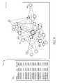
- Additional visual indicatorsmay be used in conjunction with the representation of the entities themselves. For example, with each entity being represented by a node in the visual representation, the size of the nodes can be used to indicate the number of different concepts contained in the various messages sent and/or received by that entity.
- graph 500will also include optional table 580 .
- Table 580is constructed to provide a tabular or list view of certain data related to the visual representation displayed in graph 500 .
- Table 580may include a variety of information including a list of entities along with the number of messages sent and/or received. Additionally, table 580 may contain a list of concepts contained in the messages displayed in graph 500 . The use of table 580 provides additional analytical opportunities that are not typically available absent the use of table 580 .
Landscapes
- Engineering & Computer Science (AREA)
- Business, Economics & Management (AREA)
- Computer Networks & Wireless Communication (AREA)
- Signal Processing (AREA)
- Strategic Management (AREA)
- Human Resources & Organizations (AREA)
- Theoretical Computer Science (AREA)
- Physics & Mathematics (AREA)
- Economics (AREA)
- Entrepreneurship & Innovation (AREA)
- General Physics & Mathematics (AREA)
- Marketing (AREA)
- General Business, Economics & Management (AREA)
- Tourism & Hospitality (AREA)
- Computing Systems (AREA)
- Health & Medical Sciences (AREA)
- Primary Health Care (AREA)
- Data Mining & Analysis (AREA)
- General Health & Medical Sciences (AREA)
- Operations Research (AREA)
- Quality & Reliability (AREA)
- General Engineering & Computer Science (AREA)
- Computer Hardware Design (AREA)
- Information Retrieval, Db Structures And Fs Structures Therefor (AREA)
- Information Transfer Between Computers (AREA)
Abstract
Description
Claims (8)
Priority Applications (5)
| Application Number | Priority Date | Filing Date | Title |
|---|---|---|---|
| US11/045,775US7606168B2 (en) | 2005-01-28 | 2005-01-28 | Apparatus and method for message-centric analysis and multi-aspect viewing using social networks |
| US12/581,729US8228821B2 (en) | 2005-01-28 | 2009-10-19 | System and method for generating representations of message-related relationships |
| US13/556,181US8400944B2 (en) | 2005-01-28 | 2012-07-23 | System and method for displaying message-related relationships |
| US13/831,917US8982728B2 (en) | 2005-01-28 | 2013-03-15 | Computer-implemented system and method for visualizing message-related relationships within a social network |
| US14/659,535US20150195242A1 (en) | 2005-01-28 | 2015-03-16 | Computer-Implemented System And Method For Creating And Visualizing A Social Network |
Applications Claiming Priority (1)
| Application Number | Priority Date | Filing Date | Title |
|---|---|---|---|
| US11/045,775US7606168B2 (en) | 2005-01-28 | 2005-01-28 | Apparatus and method for message-centric analysis and multi-aspect viewing using social networks |
Related Child Applications (1)
| Application Number | Title | Priority Date | Filing Date |
|---|---|---|---|
| US12/581,729ContinuationUS8228821B2 (en) | 2005-01-28 | 2009-10-19 | System and method for generating representations of message-related relationships |
Publications (2)
| Publication Number | Publication Date |
|---|---|
| US20060173957A1 US20060173957A1 (en) | 2006-08-03 |
| US7606168B2true US7606168B2 (en) | 2009-10-20 |
Family
ID=36757951
Family Applications (5)
| Application Number | Title | Priority Date | Filing Date |
|---|---|---|---|
| US11/045,775Active2027-08-04US7606168B2 (en) | 2005-01-28 | 2005-01-28 | Apparatus and method for message-centric analysis and multi-aspect viewing using social networks |
| US12/581,729Expired - Fee RelatedUS8228821B2 (en) | 2005-01-28 | 2009-10-19 | System and method for generating representations of message-related relationships |
| US13/556,181Expired - LifetimeUS8400944B2 (en) | 2005-01-28 | 2012-07-23 | System and method for displaying message-related relationships |
| US13/831,917Expired - LifetimeUS8982728B2 (en) | 2005-01-28 | 2013-03-15 | Computer-implemented system and method for visualizing message-related relationships within a social network |
| US14/659,535AbandonedUS20150195242A1 (en) | 2005-01-28 | 2015-03-16 | Computer-Implemented System And Method For Creating And Visualizing A Social Network |
Family Applications After (4)
| Application Number | Title | Priority Date | Filing Date |
|---|---|---|---|
| US12/581,729Expired - Fee RelatedUS8228821B2 (en) | 2005-01-28 | 2009-10-19 | System and method for generating representations of message-related relationships |
| US13/556,181Expired - LifetimeUS8400944B2 (en) | 2005-01-28 | 2012-07-23 | System and method for displaying message-related relationships |
| US13/831,917Expired - LifetimeUS8982728B2 (en) | 2005-01-28 | 2013-03-15 | Computer-implemented system and method for visualizing message-related relationships within a social network |
| US14/659,535AbandonedUS20150195242A1 (en) | 2005-01-28 | 2015-03-16 | Computer-Implemented System And Method For Creating And Visualizing A Social Network |
Country Status (1)
| Country | Link |
|---|---|
| US (5) | US7606168B2 (en) |
Cited By (37)
| Publication number | Priority date | Publication date | Assignee | Title |
|---|---|---|---|---|
| US20070192299A1 (en)* | 2005-12-14 | 2007-08-16 | Mark Zuckerberg | Systems and methods for social mapping |
| US20090187864A1 (en)* | 2008-01-17 | 2009-07-23 | Microsoft Corporation | Dynamically Scalable Hierarchy Navigation |
| US20090198530A1 (en)* | 2008-01-31 | 2009-08-06 | International Business Machines Corporation | Automated solution for managing ancillary working relationships in an organization |
| US20090327928A1 (en)* | 2008-03-05 | 2009-12-31 | Anastasia Dedis | Method and System Facilitating Two-Way Interactive Communication and Relationship Management |
| US20100169326A1 (en)* | 2008-12-31 | 2010-07-01 | Nokia Corporation | Method, apparatus and computer program product for providing analysis and visualization of content items association |
| US20110153635A1 (en)* | 2009-12-21 | 2011-06-23 | International Business Machines Corporation | Interactive Visualization of Sender and Recipient Information In Electronic Communications |
| US20110161827A1 (en)* | 2008-03-05 | 2011-06-30 | Anastasia Dedis | Social media communication and contact organization |
| US20110249002A1 (en)* | 2010-04-13 | 2011-10-13 | Microsoft Corporation | Manipulation and management of links and nodes in large graphs |
| US20120250950A1 (en)* | 2011-03-29 | 2012-10-04 | Phaedra Papakipos | Face Recognition Based on Spatial and Temporal Proximity |
| US20130117688A1 (en)* | 2011-11-07 | 2013-05-09 | Gface Gmbh | Displaying Contact Nodes in an Online Social Network |
| US20130173633A1 (en)* | 2011-12-28 | 2013-07-04 | Brian Piepgrass | Social Discovery and Ranking of Pages |
| US8495001B2 (en) | 2008-08-29 | 2013-07-23 | Primal Fusion Inc. | Systems and methods for semantic concept definition and semantic concept relationship synthesis utilizing existing domain definitions |
| US8510302B2 (en) | 2006-08-31 | 2013-08-13 | Primal Fusion Inc. | System, method, and computer program for a consumer defined information architecture |
| US20140015837A1 (en)* | 2012-07-16 | 2014-01-16 | Sap Ag | Visually Representing Entity Relationships |
| US8676732B2 (en) | 2008-05-01 | 2014-03-18 | Primal Fusion Inc. | Methods and apparatus for providing information of interest to one or more users |
| US8676722B2 (en) | 2008-05-01 | 2014-03-18 | Primal Fusion Inc. | Method, system, and computer program for user-driven dynamic generation of semantic networks and media synthesis |
| US8768804B2 (en) | 2011-05-06 | 2014-07-01 | SynerScope B.V. | Data analysis system |
| US8825760B1 (en) | 2010-08-10 | 2014-09-02 | Scott C. Harris | Event planning system that provides social network functions in advance of an actual event |
| US8849860B2 (en) | 2005-03-30 | 2014-09-30 | Primal Fusion Inc. | Systems and methods for applying statistical inference techniques to knowledge representations |
| US9043238B2 (en) | 2011-05-06 | 2015-05-26 | SynerScope B.V. | Data visualization system |
| US9092516B2 (en) | 2011-06-20 | 2015-07-28 | Primal Fusion Inc. | Identifying information of interest based on user preferences |
| US9104779B2 (en) | 2005-03-30 | 2015-08-11 | Primal Fusion Inc. | Systems and methods for analyzing and synthesizing complex knowledge representations |
| US9177248B2 (en) | 2005-03-30 | 2015-11-03 | Primal Fusion Inc. | Knowledge representation systems and methods incorporating customization |
| US9235806B2 (en) | 2010-06-22 | 2016-01-12 | Primal Fusion Inc. | Methods and devices for customizing knowledge representation systems |
| US9262520B2 (en) | 2009-11-10 | 2016-02-16 | Primal Fusion Inc. | System, method and computer program for creating and manipulating data structures using an interactive graphical interface |
| US9292855B2 (en) | 2009-09-08 | 2016-03-22 | Primal Fusion Inc. | Synthesizing messaging using context provided by consumers |
| US9361365B2 (en) | 2008-05-01 | 2016-06-07 | Primal Fusion Inc. | Methods and apparatus for searching of content using semantic synthesis |
| US9378203B2 (en) | 2008-05-01 | 2016-06-28 | Primal Fusion Inc. | Methods and apparatus for providing information of interest to one or more users |
| US9384572B2 (en) | 2011-05-06 | 2016-07-05 | SynerScope B.V. | Data analysis system |
| US9444907B2 (en) | 2005-12-14 | 2016-09-13 | Facebook, Inc. | Prediction of user response to invitations in a social network system based on keywords in the user's profile |
| US9876751B2 (en)* | 2011-02-23 | 2018-01-23 | Blazent, Inc. | System and method for analyzing messages in a network or across networks |
| US10002325B2 (en) | 2005-03-30 | 2018-06-19 | Primal Fusion Inc. | Knowledge representation systems and methods incorporating inference rules |
| US20190068459A1 (en)* | 2017-08-22 | 2019-02-28 | Moovila, Inc. | Systems and methods for electron flow rendering and visualization correction |
| US10248669B2 (en) | 2010-06-22 | 2019-04-02 | Primal Fusion Inc. | Methods and devices for customizing knowledge representation systems |
| US10769290B2 (en)* | 2007-05-11 | 2020-09-08 | Fair Isaac Corporation | Systems and methods for fraud detection via interactive link analysis |
| US11294977B2 (en) | 2011-06-20 | 2022-04-05 | Primal Fusion Inc. | Techniques for presenting content to a user based on the user's preferences |
| US11463579B2 (en) | 2018-12-11 | 2022-10-04 | Nextiva, Inc. | System and method of capturing, tracking, composing, analyzing and automating analog and digital interactions |
Families Citing this family (231)
| Publication number | Priority date | Publication date | Assignee | Title |
|---|---|---|---|---|
| US8862670B1 (en)* | 2006-01-26 | 2014-10-14 | Stratify, Inc. | Systems and methods for interactively analyzing communication chains based on messages |
| US9336333B2 (en)* | 2006-02-13 | 2016-05-10 | Linkedin Corporation | Searching and reference checking within social networks |
| US7764701B1 (en) | 2006-02-22 | 2010-07-27 | Qurio Holdings, Inc. | Methods, systems, and products for classifying peer systems |
| US7779004B1 (en) | 2006-02-22 | 2010-08-17 | Qurio Holdings, Inc. | Methods, systems, and products for characterizing target systems |
| US7865551B2 (en)* | 2006-05-05 | 2011-01-04 | Sony Online Entertainment Llc | Determining influential/popular participants in a communication network |
| US7992171B2 (en) | 2006-09-06 | 2011-08-02 | Qurio Holdings, Inc. | System and method for controlled viral distribution of digital content in a social network |
| US7873988B1 (en) | 2006-09-06 | 2011-01-18 | Qurio Holdings, Inc. | System and method for rights propagation and license management in conjunction with distribution of digital content in a social network |
| US20080086431A1 (en)* | 2006-09-15 | 2008-04-10 | Icebreaker, Inc. | Social interaction messaging and notification |
| US7801971B1 (en) | 2006-09-26 | 2010-09-21 | Qurio Holdings, Inc. | Systems and methods for discovering, creating, using, and managing social network circuits |
| US7925592B1 (en) | 2006-09-27 | 2011-04-12 | Qurio Holdings, Inc. | System and method of using a proxy server to manage lazy content distribution in a social network |
| US7953750B1 (en) | 2006-09-28 | 2011-05-31 | Verint Americas, Inc. | Systems and methods for storing and searching data in a customer center environment |
| US8554827B2 (en) | 2006-09-29 | 2013-10-08 | Qurio Holdings, Inc. | Virtual peer for a content sharing system |
| US7782866B1 (en) | 2006-09-29 | 2010-08-24 | Qurio Holdings, Inc. | Virtual peer in a peer-to-peer network |
| US7886334B1 (en) | 2006-12-11 | 2011-02-08 | Qurio Holdings, Inc. | System and method for social network trust assessment |
| US8346864B1 (en) | 2006-12-13 | 2013-01-01 | Qurio Holdings, Inc. | Systems and methods for social network based conferencing |
| US7698380B1 (en) | 2006-12-14 | 2010-04-13 | Qurio Holdings, Inc. | System and method of optimizing social networks and user levels based on prior network interactions |
| US7730216B1 (en) | 2006-12-14 | 2010-06-01 | Qurio Holdings, Inc. | System and method of sharing content among multiple social network nodes using an aggregation node |
| US9754273B2 (en)* | 2006-12-19 | 2017-09-05 | Microsoft Technology Licensing, Llc | Enterprise resource tracking of knowledge |
| US9195996B1 (en) | 2006-12-27 | 2015-11-24 | Qurio Holdings, Inc. | System and method for classification of communication sessions in a social network |
| US8135800B1 (en) | 2006-12-27 | 2012-03-13 | Qurio Holdings, Inc. | System and method for user classification based on social network aware content analysis |
| US8290967B2 (en)* | 2007-04-19 | 2012-10-16 | Barnesandnoble.Com Llc | Indexing and search query processing |
| US7904457B2 (en) | 2007-05-30 | 2011-03-08 | International Business Machines Corporation | Semantic correlation for flow analysis in messaging systems |
| US7991910B2 (en) | 2008-11-17 | 2011-08-02 | Amazon Technologies, Inc. | Updating routing information based on client location |
| US8028090B2 (en) | 2008-11-17 | 2011-09-27 | Amazon Technologies, Inc. | Request routing utilizing client location information |
| US8239382B2 (en)* | 2007-07-12 | 2012-08-07 | International Business Machines Corporation | Method and apparatus for creating an index of network data for a set of messages |
| US7895284B2 (en)* | 2007-11-29 | 2011-02-22 | Yahoo! Inc. | Social news ranking using gossip distance |
| US8676887B2 (en) | 2007-11-30 | 2014-03-18 | Yahoo! Inc. | Social news forwarding to generate interest clusters |
| US7954058B2 (en)* | 2007-12-14 | 2011-05-31 | Yahoo! Inc. | Sharing of content and hop distance over a social network |
| US8260882B2 (en)* | 2007-12-14 | 2012-09-04 | Yahoo! Inc. | Sharing of multimedia and relevance measure based on hop distance in a social network |
| US20090187559A1 (en)* | 2008-01-17 | 2009-07-23 | Peter Gloor | Method of analyzing unstructured documents to predict asset value performance |
| JP5375619B2 (en)* | 2008-02-12 | 2013-12-25 | 日本電気株式会社 | Information distribution apparatus, terminal, information distribution system, method and program |
| RU2010133882A (en) | 2008-02-15 | 2012-03-27 | Йо Нэт Вёкс, Инк. (Us) | DEVICE, METHOD AND COMPUTER SOFTWARE PRODUCT TO ENSURE INTERACTION BETWEEN THE FIRST USER AND SECOND USER OF SOCIAL NETWORK |
| US7962597B2 (en) | 2008-03-31 | 2011-06-14 | Amazon Technologies, Inc. | Request routing based on class |
| US8321568B2 (en) | 2008-03-31 | 2012-11-27 | Amazon Technologies, Inc. | Content management |
| US8606996B2 (en) | 2008-03-31 | 2013-12-10 | Amazon Technologies, Inc. | Cache optimization |
| US8447831B1 (en) | 2008-03-31 | 2013-05-21 | Amazon Technologies, Inc. | Incentive driven content delivery |
| US8156243B2 (en) | 2008-03-31 | 2012-04-10 | Amazon Technologies, Inc. | Request routing |
| US7970820B1 (en) | 2008-03-31 | 2011-06-28 | Amazon Technologies, Inc. | Locality based content distribution |
| US8533293B1 (en) | 2008-03-31 | 2013-09-10 | Amazon Technologies, Inc. | Client side cache management |
| US8601090B1 (en) | 2008-03-31 | 2013-12-03 | Amazon Technologies, Inc. | Network resource identification |
| US7925782B2 (en) | 2008-06-30 | 2011-04-12 | Amazon Technologies, Inc. | Request routing using network computing components |
| US9912740B2 (en) | 2008-06-30 | 2018-03-06 | Amazon Technologies, Inc. | Latency measurement in resource requests |
| US9407681B1 (en) | 2010-09-28 | 2016-08-02 | Amazon Technologies, Inc. | Latency measurement in resource requests |
| WO2010014852A1 (en)* | 2008-07-30 | 2010-02-04 | Kevin Francis Eustice | Social network model for semantic processing |
| US20100031198A1 (en)* | 2008-07-30 | 2010-02-04 | Michael Zimmerman | Data-Oriented User Interface for Mobile Device |
| US20110107427A1 (en)* | 2008-08-14 | 2011-05-05 | Searete Llc, A Limited Liability Corporation Of The State Of Delaware | Obfuscating reception of communiqué affiliated with a source entity in response to receiving information indicating reception of the communiqué |
| US8929208B2 (en) | 2008-08-14 | 2015-01-06 | The Invention Science Fund I, Llc | Conditionally releasing a communiqué determined to be affiliated with a particular source entity in response to detecting occurrence of one or more environmental aspects |
| US8850044B2 (en) | 2008-08-14 | 2014-09-30 | The Invention Science Fund I, Llc | Obfuscating identity of a source entity affiliated with a communique in accordance with conditional directive provided by a receiving entity |
| US9659188B2 (en) | 2008-08-14 | 2017-05-23 | Invention Science Fund I, Llc | Obfuscating identity of a source entity affiliated with a communiqué directed to a receiving user and in accordance with conditional directive provided by the receiving use |
| US8583553B2 (en) | 2008-08-14 | 2013-11-12 | The Invention Science Fund I, Llc | Conditionally obfuscating one or more secret entities with respect to one or more billing statements related to one or more communiqués addressed to the one or more secret entities |
| US8626848B2 (en) | 2008-08-14 | 2014-01-07 | The Invention Science Fund I, Llc | Obfuscating identity of a source entity affiliated with a communiqué in accordance with conditional directive provided by a receiving entity |
| US8730836B2 (en) | 2008-08-14 | 2014-05-20 | The Invention Science Fund I, Llc | Conditionally intercepting data indicating one or more aspects of a communiqué to obfuscate the one or more aspects of the communiqué |
| US20100318595A1 (en)* | 2008-08-14 | 2010-12-16 | Searete Llc, A Limited Liability Corporation Of The State Of Delaware | System and method for conditionally transmitting one or more locum tenentes |
| US9641537B2 (en) | 2008-08-14 | 2017-05-02 | Invention Science Fund I, Llc | Conditionally releasing a communiqué determined to be affiliated with a particular source entity in response to detecting occurrence of one or more environmental aspects |
| US20100082751A1 (en) | 2008-09-29 | 2010-04-01 | Microsoft Corporation | User perception of electronic messaging |
| US8711147B2 (en)* | 2008-10-01 | 2014-04-29 | International Business Machines Corporation | Method and system for generating and displaying an interactive dynamic graph view of multiply connected objects |
| US8194075B2 (en)* | 2008-10-01 | 2012-06-05 | International Business Machines Corporation | Method and system for generating and displaying an interactive dynamic list view of multiply connected objects |
| US8665274B2 (en)* | 2008-10-01 | 2014-03-04 | International Business Machines Corporation | Method and system for generating and displaying an interactive dynamic view of bi-directional impact analysis results for multiply connected objects |
| US8669982B2 (en)* | 2008-10-01 | 2014-03-11 | International Business Machines Corporation | Method and system for generating and displaying an interactive dynamic culling graph view of multiply connected objects |
| US8711148B2 (en)* | 2008-10-01 | 2014-04-29 | International Business Machines Corporation | Method and system for generating and displaying an interactive dynamic selective view of multiply connected objects |
| WO2010043211A2 (en)* | 2008-10-16 | 2010-04-22 | Christian Krois | Navigation device for arranging entities in a data space and method therefor, and computer comprising the navigation device |
| US8375024B2 (en)* | 2008-11-13 | 2013-02-12 | Buzzient, Inc. | Modeling social networks using analytic measurements of online social media content |
| US8060616B1 (en) | 2008-11-17 | 2011-11-15 | Amazon Technologies, Inc. | Managing CDN registration by a storage provider |
| US8073940B1 (en) | 2008-11-17 | 2011-12-06 | Amazon Technologies, Inc. | Managing content delivery network service providers |
| US8122098B1 (en) | 2008-11-17 | 2012-02-21 | Amazon Technologies, Inc. | Managing content delivery network service providers by a content broker |
| US8732309B1 (en) | 2008-11-17 | 2014-05-20 | Amazon Technologies, Inc. | Request routing utilizing cost information |
| US8521880B1 (en) | 2008-11-17 | 2013-08-27 | Amazon Technologies, Inc. | Managing content delivery network service providers |
| US8065417B1 (en) | 2008-11-17 | 2011-11-22 | Amazon Technologies, Inc. | Service provider registration by a content broker |
| US9281963B2 (en)* | 2008-12-23 | 2016-03-08 | Persistent Systems Limited | Method and system for email search |
| US20100174747A1 (en)* | 2009-01-06 | 2010-07-08 | International Business Machines Corporation | Methods for recommending new individuals to be invited into a confirmed social network based on mined social data |
| US20100174998A1 (en) | 2009-01-06 | 2010-07-08 | Kiha Software Inc. | Calendaring Location-Based Events and Associated Travel |
| US9076125B2 (en)* | 2009-02-27 | 2015-07-07 | Microsoft Technology Licensing, Llc | Visualization of participant relationships and sentiment for electronic messaging |
| US8521851B1 (en) | 2009-03-27 | 2013-08-27 | Amazon Technologies, Inc. | DNS query processing using resource identifiers specifying an application broker |
| US8756341B1 (en) | 2009-03-27 | 2014-06-17 | Amazon Technologies, Inc. | Request routing utilizing popularity information |
| US8688837B1 (en) | 2009-03-27 | 2014-04-01 | Amazon Technologies, Inc. | Dynamically translating resource identifiers for request routing using popularity information |
| US8412823B1 (en) | 2009-03-27 | 2013-04-02 | Amazon Technologies, Inc. | Managing tracking information entries in resource cache components |
| US8782236B1 (en) | 2009-06-16 | 2014-07-15 | Amazon Technologies, Inc. | Managing resources using resource expiration data |
| WO2011000404A1 (en)* | 2009-06-29 | 2011-01-06 | Nokia Siemens Networks Oy | Generating relational indicators based on analysis of telecommunications events |
| US20110004692A1 (en)* | 2009-07-01 | 2011-01-06 | Tom Occhino | Gathering Information about Connections in a Social Networking Service |
| US10210481B2 (en)* | 2009-07-14 | 2019-02-19 | Bitvore Corp. | Relational presentation of communications and application for transaction analysis |
| US9069862B1 (en) | 2010-10-14 | 2015-06-30 | Aro, Inc. | Object-based relationship search using a plurality of sub-queries |
| US11620660B2 (en) | 2009-08-19 | 2023-04-04 | Oracle International Corporation | Systems and methods for creating and inserting application media content into social media system displays |
| US10339541B2 (en) | 2009-08-19 | 2019-07-02 | Oracle International Corporation | Systems and methods for creating and inserting application media content into social media system displays |
| US20120011432A1 (en) | 2009-08-19 | 2012-01-12 | Vitrue, Inc. | Systems and methods for associating social media systems and web pages |
| US8397073B1 (en) | 2009-09-04 | 2013-03-12 | Amazon Technologies, Inc. | Managing secure content in a content delivery network |
| WO2011030100A2 (en)* | 2009-09-10 | 2011-03-17 | Liverpool John Moores University | Analysis method |
| US20110078188A1 (en)* | 2009-09-28 | 2011-03-31 | Microsoft Corporation | Mining and Conveying Social Relationships |
| US8429275B2 (en)* | 2009-09-29 | 2013-04-23 | At&T Intellectual Property I, L.P. | Method and apparatus for creating a social network map of non-voice communications |
| US8433771B1 (en) | 2009-10-02 | 2013-04-30 | Amazon Technologies, Inc. | Distribution network with forward resource propagation |
| JP2011145794A (en)* | 2010-01-13 | 2011-07-28 | Nintendo Co Ltd | Program, apparatus, method, and system for processing information |
| US20110173316A1 (en)* | 2010-01-13 | 2011-07-14 | c/o Microsoft Corporation | Relationship based representation of participants in shared online space |
| US9495338B1 (en) | 2010-01-28 | 2016-11-15 | Amazon Technologies, Inc. | Content distribution network |
| US8509733B2 (en)* | 2010-04-28 | 2013-08-13 | Verint Americas, Inc. | System and method for determining commonly used communication terminals and for identifying noisy entities in large-scale link analysis |
| KR101865710B1 (en)* | 2010-05-06 | 2018-06-11 | 순 텍크 프레데릭 노엘 리아우 | System and method for directing content to users of a social networking engine |
| US20120130940A1 (en) | 2010-11-18 | 2012-05-24 | Wal-Mart Stores, Inc. | Real-time analytics of streaming data |
| US8577992B1 (en) | 2010-09-28 | 2013-11-05 | Amazon Technologies, Inc. | Request routing management based on network components |
| US9712484B1 (en) | 2010-09-28 | 2017-07-18 | Amazon Technologies, Inc. | Managing request routing information utilizing client identifiers |
| US8819283B2 (en) | 2010-09-28 | 2014-08-26 | Amazon Technologies, Inc. | Request routing in a networked environment |
| US10958501B1 (en) | 2010-09-28 | 2021-03-23 | Amazon Technologies, Inc. | Request routing information based on client IP groupings |
| US10097398B1 (en) | 2010-09-28 | 2018-10-09 | Amazon Technologies, Inc. | Point of presence management in request routing |
| US8468247B1 (en) | 2010-09-28 | 2013-06-18 | Amazon Technologies, Inc. | Point of presence management in request routing |
| US9003035B1 (en) | 2010-09-28 | 2015-04-07 | Amazon Technologies, Inc. | Point of presence management in request routing |
| US8429099B1 (en) | 2010-10-14 | 2013-04-23 | Aro, Inc. | Dynamic gazetteers for entity recognition and fact association |
| US20120117515A1 (en)* | 2010-11-05 | 2012-05-10 | Nokia Corporation | Method and apparatus for generating a visual representation of information |
| US8452874B2 (en) | 2010-11-22 | 2013-05-28 | Amazon Technologies, Inc. | Request routing processing |
| US9391949B1 (en) | 2010-12-03 | 2016-07-12 | Amazon Technologies, Inc. | Request routing processing |
| US20120158935A1 (en)* | 2010-12-21 | 2012-06-21 | Sony Corporation | Method and systems for managing social networks |
| CN102651719B (en) | 2011-02-28 | 2016-08-31 | 国际商业机器公司 | For the method and apparatus following the tracks of message topic in message interaction environment |
| US8743122B2 (en) | 2011-03-07 | 2014-06-03 | Microsoft Corporation | Interactive visualization for exploring multi-modal, multi-relational, and multivariate graph data |
| US10467042B1 (en) | 2011-04-27 | 2019-11-05 | Amazon Technologies, Inc. | Optimized deployment based upon customer locality |
| US8700756B2 (en)* | 2011-05-03 | 2014-04-15 | Xerox Corporation | Systems, methods and devices for extracting and visualizing user-centric communities from emails |
| US8560681B2 (en)* | 2011-05-10 | 2013-10-15 | Telefonica, S.A. | Method of characterizing a social network communication using motifs |
| US8751621B2 (en)* | 2011-06-16 | 2014-06-10 | Radiumone, Inc. | Building a social graph based on links received and selected by receiving users of the open web |
| US9606694B2 (en) | 2011-06-20 | 2017-03-28 | Tandemseven, Inc. | System and method for building and managing user experience for computer software interfaces |
| ES2751133T3 (en)* | 2011-06-29 | 2020-03-30 | Orange | Notification engine |
| US20230153347A1 (en)* | 2011-07-05 | 2023-05-18 | Michael Stewart Shunock | System and method for annotating images |
| US8725796B2 (en)* | 2011-07-07 | 2014-05-13 | F. David Serena | Relationship networks having link quality metrics with inference and concomitant digital value exchange |
| US8713455B2 (en)* | 2011-10-24 | 2014-04-29 | Google Inc. | Techniques for generating and displaying a visual flow of user content through a social network |
| EP2769292A4 (en)* | 2012-01-27 | 2015-01-07 | Bottlenose Inc | Trending of aggregated personalized information streams and multi-dimensional graphical depiction thereof |
| GB2512574A (en)* | 2012-01-27 | 2014-10-08 | Bottlenose Inc | Trending of aggregated personalized information streams and multi-dimensional graphical depiction thereof |
| US9430738B1 (en) | 2012-02-08 | 2016-08-30 | Mashwork, Inc. | Automated emotional clustering of social media conversations |
| US8904009B1 (en)* | 2012-02-10 | 2014-12-02 | Amazon Technologies, Inc. | Dynamic content delivery |
| US8543647B2 (en)* | 2012-02-15 | 2013-09-24 | Facebook, Inc. | Automated customer incident report management in a social networking system |
| WO2013123462A1 (en)* | 2012-02-15 | 2013-08-22 | Bottlenose, Inc. | Systems and methods for recommending advertisement placement based on cross network online activity analysis |
| US8832092B2 (en) | 2012-02-17 | 2014-09-09 | Bottlenose, Inc. | Natural language processing optimized for micro content |
| US10021179B1 (en) | 2012-02-21 | 2018-07-10 | Amazon Technologies, Inc. | Local resource delivery network |
| US9489657B2 (en)* | 2012-02-21 | 2016-11-08 | Microsoft Technology Licensing, Llc | Aggregation and visualization of multiple chat room information |
| US20130254699A1 (en)* | 2012-03-21 | 2013-09-26 | Intertrust Technologies Corporation | Systems and methods for managing documents and other electronic content |
| US10623408B1 (en) | 2012-04-02 | 2020-04-14 | Amazon Technologies, Inc. | Context sensitive object management |
| US9154551B1 (en) | 2012-06-11 | 2015-10-06 | Amazon Technologies, Inc. | Processing DNS queries to identify pre-processing information |
| JP2014016916A (en)* | 2012-07-11 | 2014-01-30 | International Business Maschines Corporation | Social graph expanding method, program and system |
| US9009126B2 (en) | 2012-07-31 | 2015-04-14 | Bottlenose, Inc. | Discovering and ranking trending links about topics |
| WO2014031618A2 (en) | 2012-08-22 | 2014-02-27 | Bitvore Corp. | Data relationships storage platform |
| US9525659B1 (en) | 2012-09-04 | 2016-12-20 | Amazon Technologies, Inc. | Request routing utilizing point of presence load information |
| US9727925B2 (en)* | 2012-09-09 | 2017-08-08 | Oracle International Corporation | Method and system for implementing semantic analysis of internal social network content |
| US9323577B2 (en) | 2012-09-20 | 2016-04-26 | Amazon Technologies, Inc. | Automated profiling of resource usage |
| US10205698B1 (en) | 2012-12-19 | 2019-02-12 | Amazon Technologies, Inc. | Source-dependent address resolution |
| US8954546B2 (en) | 2013-01-25 | 2015-02-10 | Concurix Corporation | Tracing with a workload distributor |
| US20140019879A1 (en)* | 2013-02-01 | 2014-01-16 | Concurix Corporation | Dynamic Visualization of Message Passing Computation |
| US9256969B2 (en) | 2013-02-01 | 2016-02-09 | Microsoft Technology Licensing, Llc | Transformation function insertion for dynamically displayed tracer data |
| US9323863B2 (en)* | 2013-02-01 | 2016-04-26 | Microsoft Technology Licensing, Llc | Highlighting of time series data on force directed graph |
| US20130283281A1 (en) | 2013-02-12 | 2013-10-24 | Concurix Corporation | Deploying Trace Objectives using Cost Analyses |
| US8843901B2 (en) | 2013-02-12 | 2014-09-23 | Concurix Corporation | Cost analysis for selecting trace objectives |
| US8924941B2 (en) | 2013-02-12 | 2014-12-30 | Concurix Corporation | Optimization analysis using similar frequencies |
| US8997063B2 (en) | 2013-02-12 | 2015-03-31 | Concurix Corporation | Periodicity optimization in an automated tracing system |
| US9021447B2 (en) | 2013-02-12 | 2015-04-28 | Concurix Corporation | Application tracing by distributed objectives |
| US8762302B1 (en) | 2013-02-22 | 2014-06-24 | Bottlenose, Inc. | System and method for revealing correlations between data streams |
| US20130219372A1 (en) | 2013-03-15 | 2013-08-22 | Concurix Corporation | Runtime Settings Derived from Relationships Identified in Tracer Data |
| US9575874B2 (en) | 2013-04-20 | 2017-02-21 | Microsoft Technology Licensing, Llc | Error list and bug report analysis for configuring an application tracer |
| US9929916B1 (en) | 2013-05-02 | 2018-03-27 | Aspen Technology, Inc. | Achieving stateful application software service behavior in distributed stateless systems |
| US10019531B2 (en)* | 2013-05-19 | 2018-07-10 | Carmel Kent | System and method for displaying, connecting and analyzing data in an online collaborative webpage |
| US9734040B2 (en) | 2013-05-21 | 2017-08-15 | Microsoft Technology Licensing, Llc | Animated highlights in a graph representing an application |
| US8990777B2 (en) | 2013-05-21 | 2015-03-24 | Concurix Corporation | Interactive graph for navigating and monitoring execution of application code |
| US9294391B1 (en) | 2013-06-04 | 2016-03-22 | Amazon Technologies, Inc. | Managing network computing components utilizing request routing |
| USD738394S1 (en)* | 2013-06-09 | 2015-09-08 | Apple Inc. | Display screen or portion thereof with animated graphical user interface |
| USD741350S1 (en) | 2013-06-10 | 2015-10-20 | Apple Inc. | Display screen or portion thereof with animated graphical user interface |
| US9280841B2 (en) | 2013-07-24 | 2016-03-08 | Microsoft Technology Licensing, Llc | Event chain visualization of performance data |
| US9639610B1 (en)* | 2013-08-05 | 2017-05-02 | Hrl Laboratories, Llc | Method for gauging public interest in a topic using network analysis of online discussions |
| US9213778B2 (en) | 2013-08-12 | 2015-12-15 | International Business Machines Corporation | Social network posting analysis using degree of separation correlation |
| US10430420B2 (en) | 2013-08-16 | 2019-10-01 | International Business Machines Corporation | Weighting sentiment information |
| US9292415B2 (en) | 2013-09-04 | 2016-03-22 | Microsoft Technology Licensing, Llc | Module specific tracing in a shared module environment |
| WO2015035351A1 (en) | 2013-09-09 | 2015-03-12 | UnitedLex Corp. | Interactive case management system |
| US9785317B2 (en)* | 2013-09-24 | 2017-10-10 | Palantir Technologies Inc. | Presentation and analysis of user interaction data |
| US20150095431A1 (en)* | 2013-09-30 | 2015-04-02 | Microsoft Corporation | View of information relating to a relationship between entities |
| US8812960B1 (en) | 2013-10-07 | 2014-08-19 | Palantir Technologies Inc. | Cohort-based presentation of user interaction data |
| CN105765560B (en) | 2013-11-13 | 2019-11-05 | 微软技术许可有限责任公司 | The component software executed based on multiple tracking is recommended |
| WO2015071778A1 (en) | 2013-11-13 | 2015-05-21 | Concurix Corporation | Application execution path tracing with configurable origin definition |
| US10628748B2 (en) | 2013-12-03 | 2020-04-21 | University Of Massachusetts | System and methods for predicting probable relationships between items |
| US10089691B2 (en)* | 2013-12-04 | 2018-10-02 | State Farm Mutual Automobile Insurance Company | Systems and methods for detecting potentially inaccurate insurance claims |
| USD750123S1 (en) | 2014-02-14 | 2016-02-23 | Aspen Technology, Inc. | Display screen with graphical user interface |
| US10922657B2 (en) | 2014-08-26 | 2021-02-16 | Oracle International Corporation | Using an employee database with social media connections to calculate job candidate reputation scores |
| US10091096B1 (en) | 2014-12-18 | 2018-10-02 | Amazon Technologies, Inc. | Routing mode and point-of-presence selection service |
| US10097448B1 (en) | 2014-12-18 | 2018-10-09 | Amazon Technologies, Inc. | Routing mode and point-of-presence selection service |
| US10033627B1 (en) | 2014-12-18 | 2018-07-24 | Amazon Technologies, Inc. | Routing mode and point-of-presence selection service |
| US9703845B2 (en)* | 2015-01-26 | 2017-07-11 | International Business Machines Corporation | Representing identity data relationships using graphs |
| US20160248825A1 (en)* | 2015-02-25 | 2016-08-25 | Chian Chiu Li | Registration-Free Location-Based Social Networks |
| US10565601B2 (en)* | 2015-02-27 | 2020-02-18 | The Nielsen Company (Us), Llc | Methods and apparatus to identify non-traditional asset-bundles for purchasing groups using social media |
| US10225326B1 (en) | 2015-03-23 | 2019-03-05 | Amazon Technologies, Inc. | Point of presence based data uploading |
| US10147071B2 (en)* | 2015-03-23 | 2018-12-04 | International Business Machines Corporation | Visual representation of an email chain |
| US9887931B1 (en) | 2015-03-30 | 2018-02-06 | Amazon Technologies, Inc. | Traffic surge management for points of presence |
| US9887932B1 (en) | 2015-03-30 | 2018-02-06 | Amazon Technologies, Inc. | Traffic surge management for points of presence |
| US9819567B1 (en) | 2015-03-30 | 2017-11-14 | Amazon Technologies, Inc. | Traffic surge management for points of presence |
| US9832141B1 (en) | 2015-05-13 | 2017-11-28 | Amazon Technologies, Inc. | Routing based request correlation |
| US9948586B2 (en)* | 2015-05-29 | 2018-04-17 | International Business Machines Corporation | Intelligent information sharing system |
| US9948580B2 (en)* | 2015-06-19 | 2018-04-17 | Whatsapp Inc. | Techniques to replicate data using uploads from messaging clients |
| US10616179B1 (en) | 2015-06-25 | 2020-04-07 | Amazon Technologies, Inc. | Selective routing of domain name system (DNS) requests |
| US10268773B2 (en) | 2015-06-30 | 2019-04-23 | International Business Machines Corporation | Navigating a website using visual analytics and a dynamic data source |
| US10025799B2 (en) | 2015-07-22 | 2018-07-17 | International Business Machines Corporation | Access and presentation of files based on semantic proximity to current interests |
| US10097566B1 (en) | 2015-07-31 | 2018-10-09 | Amazon Technologies, Inc. | Identifying targets of network attacks |
| US9774619B1 (en) | 2015-09-24 | 2017-09-26 | Amazon Technologies, Inc. | Mitigating network attacks |
| US9742795B1 (en) | 2015-09-24 | 2017-08-22 | Amazon Technologies, Inc. | Mitigating network attacks |
| US9794281B1 (en) | 2015-09-24 | 2017-10-17 | Amazon Technologies, Inc. | Identifying sources of network attacks |
| US9672538B1 (en) | 2015-11-09 | 2017-06-06 | Radiumone, Inc. | Delivering personalized content based on geolocation information in a social graph with sharing activity of users of the open web |
| US10270878B1 (en) | 2015-11-10 | 2019-04-23 | Amazon Technologies, Inc. | Routing for origin-facing points of presence |
| US10257307B1 (en) | 2015-12-11 | 2019-04-09 | Amazon Technologies, Inc. | Reserved cache space in content delivery networks |
| US10049051B1 (en) | 2015-12-11 | 2018-08-14 | Amazon Technologies, Inc. | Reserved cache space in content delivery networks |
| US10348639B2 (en) | 2015-12-18 | 2019-07-09 | Amazon Technologies, Inc. | Use of virtual endpoints to improve data transmission rates |
| US10075551B1 (en) | 2016-06-06 | 2018-09-11 | Amazon Technologies, Inc. | Request management for hierarchical cache |
| US10110694B1 (en) | 2016-06-29 | 2018-10-23 | Amazon Technologies, Inc. | Adaptive transfer rate for retrieving content from a server |
| US9992086B1 (en) | 2016-08-23 | 2018-06-05 | Amazon Technologies, Inc. | External health checking of virtual private cloud network environments |
| US10033691B1 (en) | 2016-08-24 | 2018-07-24 | Amazon Technologies, Inc. | Adaptive resolution of domain name requests in virtual private cloud network environments |
| US10616250B2 (en) | 2016-10-05 | 2020-04-07 | Amazon Technologies, Inc. | Network addresses with encoded DNS-level information |
| US10831549B1 (en) | 2016-12-27 | 2020-11-10 | Amazon Technologies, Inc. | Multi-region request-driven code execution system |
| US10372499B1 (en) | 2016-12-27 | 2019-08-06 | Amazon Technologies, Inc. | Efficient region selection system for executing request-driven code |
| US10938884B1 (en) | 2017-01-30 | 2021-03-02 | Amazon Technologies, Inc. | Origin server cloaking using virtual private cloud network environments |
| US10503613B1 (en) | 2017-04-21 | 2019-12-10 | Amazon Technologies, Inc. | Efficient serving of resources during server unavailability |
| US20180341687A1 (en)* | 2017-05-24 | 2018-11-29 | International Business Machines Corporation | Identifying the subject of an ambiguous name in a communication |
| US11075987B1 (en) | 2017-06-12 | 2021-07-27 | Amazon Technologies, Inc. | Load estimating content delivery network |
| US10447648B2 (en) | 2017-06-19 | 2019-10-15 | Amazon Technologies, Inc. | Assignment of a POP to a DNS resolver based on volume of communications over a link between client devices and the POP |
| US10742593B1 (en) | 2017-09-25 | 2020-08-11 | Amazon Technologies, Inc. | Hybrid content request routing system |
| US10970349B1 (en) | 2017-10-18 | 2021-04-06 | Comake, Inc. | Workflow relationship management and contextualization |
| US11157505B2 (en) | 2017-10-18 | 2021-10-26 | Comake, Inc. | Dynamic presentation of searchable contextual actions and data |
| US10592578B1 (en) | 2018-03-07 | 2020-03-17 | Amazon Technologies, Inc. | Predictive content push-enabled content delivery network |
| CN108616845B (en)* | 2018-03-30 | 2021-10-26 | 佛山市顺德区中山大学研究院 | D2D grouping multi-target caching method based on social content and system and device thereof |
| USD877175S1 (en) | 2018-06-04 | 2020-03-03 | Apple Inc. | Electronic device with graphical user interface |
| USD883319S1 (en) | 2018-10-29 | 2020-05-05 | Apple Inc. | Electronic device with graphical user interface |
| WO2020101069A1 (en)* | 2018-11-15 | 2020-05-22 | Samsung Electronics Co., Ltd. | Method and apparatus for processing social network information |
| US10862852B1 (en) | 2018-11-16 | 2020-12-08 | Amazon Technologies, Inc. | Resolution of domain name requests in heterogeneous network environments |
| US11017162B2 (en)* | 2018-12-03 | 2021-05-25 | International Business Machines Corporation | Annotation editor with graph |
| US11025747B1 (en) | 2018-12-12 | 2021-06-01 | Amazon Technologies, Inc. | Content request pattern-based routing system |
| US11620338B1 (en)* | 2019-10-07 | 2023-04-04 | Wells Fargo Bank, N.A. | Dashboard with relationship graphing |
| US12143527B2 (en) | 2020-02-20 | 2024-11-12 | Grey Wall Software Llc | Computer messaging analytics systems and methods |
| US11238108B1 (en) | 2020-07-28 | 2022-02-01 | Grey Wall Software Llc | Custom data filtering systems and methods |
| US12182207B2 (en) | 2020-07-28 | 2024-12-31 | Grey Wall Software Llc | Custom data filtering systems and methods |
| USD956777S1 (en)* | 2020-08-11 | 2022-07-05 | Specter Ops, Inc. | Display screen or portion thereof with graphical user interface |
| USD956778S1 (en)* | 2020-08-11 | 2022-07-05 | Specter Ops, Inc. | Display screen or portion thereof with an animated graphical user interface |
| USD956779S1 (en)* | 2020-08-11 | 2022-07-05 | Specter Ops, Inc. | Display screen or portion thereof with an animated graphical user interface |
| CN111930463A (en)* | 2020-09-23 | 2020-11-13 | 杭州橙鹰数据技术有限公司 | Display method and device |
| USD1066353S1 (en)* | 2020-12-18 | 2025-03-11 | Tianning Han | Display screen or portion thereof with animated graphical user interface |
| USD984461S1 (en) | 2021-06-04 | 2023-04-25 | Apple Inc. | Display screen or portion thereof with graphical user interface |
| US12271401B2 (en) | 2022-08-31 | 2025-04-08 | Microsoft Technology Licensing, Llc | Friction reduction during professional network expansion |
Citations (5)
| Publication number | Priority date | Publication date | Assignee | Title |
|---|---|---|---|---|
| US20040148275A1 (en)* | 2003-01-29 | 2004-07-29 | Dimitris Achlioptas | System and method for employing social networks for information discovery |
| US6778995B1 (en) | 2001-08-31 | 2004-08-17 | Attenex Corporation | System and method for efficiently generating cluster groupings in a multi-dimensional concept space |
| US6820081B1 (en) | 2001-03-19 | 2004-11-16 | Attenex Corporation | System and method for evaluating a structured message store for message redundancy |
| US20060021009A1 (en)* | 2004-07-22 | 2006-01-26 | Christopher Lunt | Authorization and authentication based on an individual's social network |
| US7359894B1 (en)* | 2004-06-30 | 2008-04-15 | Google Inc. | Methods and systems for requesting and providing information in a social network |
Family Cites Families (11)
| Publication number | Priority date | Publication date | Assignee | Title |
|---|---|---|---|---|
| EP1031087A1 (en)* | 1997-07-18 | 2000-08-30 | Net Exchange, Inc. | Apparatus and method for effecting correspondent-centric electronic mail |
| US7197470B1 (en)* | 2000-10-11 | 2007-03-27 | Buzzmetrics, Ltd. | System and method for collection analysis of electronic discussion methods |
| US7366759B2 (en)* | 2001-02-22 | 2008-04-29 | Parity Communications, Inc. | Method and system for characterizing relationships in social networks |
| WO2003102740A2 (en)* | 2002-06-03 | 2003-12-11 | Arizona Board Of Regents Acting For And On Behalf Of Arizona State University | System and method of analyzing the temporal evolution of text using dynamic centering resonance analysis |
| AU2003271269A1 (en)* | 2002-06-28 | 2004-01-19 | Joseph A. Massanelli | Systems and methods for capturing and archiving email |
| US20050015767A1 (en)* | 2003-07-01 | 2005-01-20 | Brian Nash | Operating system configuration tool |
| US7503070B1 (en)* | 2003-09-19 | 2009-03-10 | Marshall Van Alstyne | Methods and systems for enabling analysis of communication content while preserving confidentiality |
| NO321340B1 (en)* | 2003-12-30 | 2006-05-02 | Telenor Asa | Method of managing networks by analyzing connectivity |
| US8015119B2 (en)* | 2004-01-21 | 2011-09-06 | Google Inc. | Methods and systems for the display and navigation of a social network |
| US7885901B2 (en)* | 2004-01-29 | 2011-02-08 | Yahoo! Inc. | Method and system for seeding online social network contacts |
| US20060122974A1 (en)* | 2004-12-03 | 2006-06-08 | Igor Perisic | System and method for a dynamic content driven rendering of social networks |
- 2005
- 2005-01-28USUS11/045,775patent/US7606168B2/enactiveActive
- 2009
- 2009-10-19USUS12/581,729patent/US8228821B2/ennot_activeExpired - Fee Related
- 2012
- 2012-07-23USUS13/556,181patent/US8400944B2/ennot_activeExpired - Lifetime
- 2013
- 2013-03-15USUS13/831,917patent/US8982728B2/ennot_activeExpired - Lifetime
- 2015
- 2015-03-16USUS14/659,535patent/US20150195242A1/ennot_activeAbandoned
Patent Citations (5)
| Publication number | Priority date | Publication date | Assignee | Title |
|---|---|---|---|---|
| US6820081B1 (en) | 2001-03-19 | 2004-11-16 | Attenex Corporation | System and method for evaluating a structured message store for message redundancy |
| US6778995B1 (en) | 2001-08-31 | 2004-08-17 | Attenex Corporation | System and method for efficiently generating cluster groupings in a multi-dimensional concept space |
| US20040148275A1 (en)* | 2003-01-29 | 2004-07-29 | Dimitris Achlioptas | System and method for employing social networks for information discovery |
| US7359894B1 (en)* | 2004-06-30 | 2008-04-15 | Google Inc. | Methods and systems for requesting and providing information in a social network |
| US20060021009A1 (en)* | 2004-07-22 | 2006-01-26 | Christopher Lunt | Authorization and authentication based on an individual's social network |
Cited By (69)
| Publication number | Priority date | Publication date | Assignee | Title |
|---|---|---|---|---|
| US9104779B2 (en) | 2005-03-30 | 2015-08-11 | Primal Fusion Inc. | Systems and methods for analyzing and synthesizing complex knowledge representations |
| US10002325B2 (en) | 2005-03-30 | 2018-06-19 | Primal Fusion Inc. | Knowledge representation systems and methods incorporating inference rules |
| US9934465B2 (en) | 2005-03-30 | 2018-04-03 | Primal Fusion Inc. | Systems and methods for analyzing and synthesizing complex knowledge representations |
| US9904729B2 (en) | 2005-03-30 | 2018-02-27 | Primal Fusion Inc. | System, method, and computer program for a consumer defined information architecture |
| US8849860B2 (en) | 2005-03-30 | 2014-09-30 | Primal Fusion Inc. | Systems and methods for applying statistical inference techniques to knowledge representations |
| US9177248B2 (en) | 2005-03-30 | 2015-11-03 | Primal Fusion Inc. | Knowledge representation systems and methods incorporating customization |
| US9183599B2 (en)* | 2005-12-14 | 2015-11-10 | Facebook, Inc. | Mapping relationships between members in a social network |
| US9444907B2 (en) | 2005-12-14 | 2016-09-13 | Facebook, Inc. | Prediction of user response to invitations in a social network system based on keywords in the user's profile |
| US9727927B2 (en) | 2005-12-14 | 2017-08-08 | Facebook, Inc. | Prediction of user response to invitations in a social networking system based on keywords in the user's profile |
| US10261970B2 (en) | 2005-12-14 | 2019-04-16 | Facebook, Inc. | Mapping relationships between members in a social network |
| US20070192299A1 (en)* | 2005-12-14 | 2007-08-16 | Mark Zuckerberg | Systems and methods for social mapping |
| US8510302B2 (en) | 2006-08-31 | 2013-08-13 | Primal Fusion Inc. | System, method, and computer program for a consumer defined information architecture |
| US10769290B2 (en)* | 2007-05-11 | 2020-09-08 | Fair Isaac Corporation | Systems and methods for fraud detection via interactive link analysis |
| US20090187864A1 (en)* | 2008-01-17 | 2009-07-23 | Microsoft Corporation | Dynamically Scalable Hierarchy Navigation |
| US20090198530A1 (en)* | 2008-01-31 | 2009-08-06 | International Business Machines Corporation | Automated solution for managing ancillary working relationships in an organization |
| US20110161827A1 (en)* | 2008-03-05 | 2011-06-30 | Anastasia Dedis | Social media communication and contact organization |
| US20090327928A1 (en)* | 2008-03-05 | 2009-12-31 | Anastasia Dedis | Method and System Facilitating Two-Way Interactive Communication and Relationship Management |
| US11182440B2 (en) | 2008-05-01 | 2021-11-23 | Primal Fusion Inc. | Methods and apparatus for searching of content using semantic synthesis |
| US9378203B2 (en) | 2008-05-01 | 2016-06-28 | Primal Fusion Inc. | Methods and apparatus for providing information of interest to one or more users |
| US8676732B2 (en) | 2008-05-01 | 2014-03-18 | Primal Fusion Inc. | Methods and apparatus for providing information of interest to one or more users |
| US9361365B2 (en) | 2008-05-01 | 2016-06-07 | Primal Fusion Inc. | Methods and apparatus for searching of content using semantic synthesis |
| US8676722B2 (en) | 2008-05-01 | 2014-03-18 | Primal Fusion Inc. | Method, system, and computer program for user-driven dynamic generation of semantic networks and media synthesis |
| US9792550B2 (en) | 2008-05-01 | 2017-10-17 | Primal Fusion Inc. | Methods and apparatus for providing information of interest to one or more users |
| US11868903B2 (en) | 2008-05-01 | 2024-01-09 | Primal Fusion Inc. | Method, system, and computer program for user-driven dynamic generation of semantic networks and media synthesis |
| US8495001B2 (en) | 2008-08-29 | 2013-07-23 | Primal Fusion Inc. | Systems and methods for semantic concept definition and semantic concept relationship synthesis utilizing existing domain definitions |
| US9595004B2 (en) | 2008-08-29 | 2017-03-14 | Primal Fusion Inc. | Systems and methods for semantic concept definition and semantic concept relationship synthesis utilizing existing domain definitions |
| US10803107B2 (en) | 2008-08-29 | 2020-10-13 | Primal Fusion Inc. | Systems and methods for semantic concept definition and semantic concept relationship synthesis utilizing existing domain definitions |
| US8943016B2 (en) | 2008-08-29 | 2015-01-27 | Primal Fusion Inc. | Systems and methods for semantic concept definition and semantic concept relationship synthesis utilizing existing domain definitions |
| US12032616B2 (en) | 2008-08-29 | 2024-07-09 | Primal Fusion Inc. | Systems and methods for semantic concept definition and semantic concept relationship synthesis utilizing existing domain definitions |
| US20100169326A1 (en)* | 2008-12-31 | 2010-07-01 | Nokia Corporation | Method, apparatus and computer program product for providing analysis and visualization of content items association |
| US9292855B2 (en) | 2009-09-08 | 2016-03-22 | Primal Fusion Inc. | Synthesizing messaging using context provided by consumers |
| US10181137B2 (en) | 2009-09-08 | 2019-01-15 | Primal Fusion Inc. | Synthesizing messaging using context provided by consumers |
| US10146843B2 (en) | 2009-11-10 | 2018-12-04 | Primal Fusion Inc. | System, method and computer program for creating and manipulating data structures using an interactive graphical interface |
| US9262520B2 (en) | 2009-11-10 | 2016-02-16 | Primal Fusion Inc. | System, method and computer program for creating and manipulating data structures using an interactive graphical interface |
| US8489588B2 (en)* | 2009-12-21 | 2013-07-16 | International Business Machines Corporation | Interactive visualization of sender and recipient information in electronic communications |
| US8819002B2 (en) | 2009-12-21 | 2014-08-26 | International Business Machines Corporation | Interactive visualization of sender and recipient information in electronic communications |
| US20110153635A1 (en)* | 2009-12-21 | 2011-06-23 | International Business Machines Corporation | Interactive Visualization of Sender and Recipient Information In Electronic Communications |
| US8810576B2 (en)* | 2010-04-13 | 2014-08-19 | Microsoft Corporation | Manipulation and management of links and nodes in large graphs |
| US20110249002A1 (en)* | 2010-04-13 | 2011-10-13 | Microsoft Corporation | Manipulation and management of links and nodes in large graphs |
| US11474979B2 (en) | 2010-06-22 | 2022-10-18 | Primal Fusion Inc. | Methods and devices for customizing knowledge representation systems |
| US9576241B2 (en) | 2010-06-22 | 2017-02-21 | Primal Fusion Inc. | Methods and devices for customizing knowledge representation systems |
| US10474647B2 (en) | 2010-06-22 | 2019-11-12 | Primal Fusion Inc. | Methods and devices for customizing knowledge representation systems |
| US9235806B2 (en) | 2010-06-22 | 2016-01-12 | Primal Fusion Inc. | Methods and devices for customizing knowledge representation systems |
| US10248669B2 (en) | 2010-06-22 | 2019-04-02 | Primal Fusion Inc. | Methods and devices for customizing knowledge representation systems |
| US8825760B1 (en) | 2010-08-10 | 2014-09-02 | Scott C. Harris | Event planning system that provides social network functions in advance of an actual event |
| US9876751B2 (en)* | 2011-02-23 | 2018-01-23 | Blazent, Inc. | System and method for analyzing messages in a network or across networks |
| US20160171291A1 (en)* | 2011-03-29 | 2016-06-16 | Facebook, Inc. | Face recognition based on spatial and temporal proximity |
| US10162999B2 (en)* | 2011-03-29 | 2018-12-25 | Facebook, Inc. | Face recognition based on spatial and temporal proximity |
| US20120250950A1 (en)* | 2011-03-29 | 2012-10-04 | Phaedra Papakipos | Face Recognition Based on Spatial and Temporal Proximity |
| US9317530B2 (en)* | 2011-03-29 | 2016-04-19 | Facebook, Inc. | Face recognition based on spatial and temporal proximity |
| US8768804B2 (en) | 2011-05-06 | 2014-07-01 | SynerScope B.V. | Data analysis system |
| US9043238B2 (en) | 2011-05-06 | 2015-05-26 | SynerScope B.V. | Data visualization system |
| US9384572B2 (en) | 2011-05-06 | 2016-07-05 | SynerScope B.V. | Data analysis system |
| US11294977B2 (en) | 2011-06-20 | 2022-04-05 | Primal Fusion Inc. | Techniques for presenting content to a user based on the user's preferences |
| US9092516B2 (en) | 2011-06-20 | 2015-07-28 | Primal Fusion Inc. | Identifying information of interest based on user preferences |
| US9715552B2 (en) | 2011-06-20 | 2017-07-25 | Primal Fusion Inc. | Techniques for presenting content to a user based on the user's preferences |
| US9098575B2 (en) | 2011-06-20 | 2015-08-04 | Primal Fusion Inc. | Preference-guided semantic processing |
| US10409880B2 (en) | 2011-06-20 | 2019-09-10 | Primal Fusion Inc. | Techniques for presenting content to a user based on the user's preferences |
| US20130117688A1 (en)* | 2011-11-07 | 2013-05-09 | Gface Gmbh | Displaying Contact Nodes in an Online Social Network |
| US20130173633A1 (en)* | 2011-12-28 | 2013-07-04 | Brian Piepgrass | Social Discovery and Ranking of Pages |
| US11048708B2 (en)* | 2011-12-28 | 2021-06-29 | Facebook, Inc. | Social discovery and ranking of pages |
| US8935261B2 (en)* | 2011-12-28 | 2015-01-13 | Facebook, Inc. | Social discovery and ranking of pages |
| US20150095324A1 (en)* | 2011-12-28 | 2015-04-02 | Facebook, Inc. | Social Discovery and Ranking of Pages |
| US9697260B2 (en)* | 2011-12-28 | 2017-07-04 | Facebook, Inc. | Social discovery and ranking of pages |
| US20140015837A1 (en)* | 2012-07-16 | 2014-01-16 | Sap Ag | Visually Representing Entity Relationships |
| US9111390B2 (en)* | 2012-07-16 | 2015-08-18 | Sap Portals Israel Ltd | Visually representing entity relationships |
| US20190068459A1 (en)* | 2017-08-22 | 2019-02-28 | Moovila, Inc. | Systems and methods for electron flow rendering and visualization correction |
| US11310121B2 (en)* | 2017-08-22 | 2022-04-19 | Moovila, Inc. | Systems and methods for electron flow rendering and visualization correction |
| US11463579B2 (en) | 2018-12-11 | 2022-10-04 | Nextiva, Inc. | System and method of capturing, tracking, composing, analyzing and automating analog and digital interactions |
Also Published As
| Publication number | Publication date |
|---|---|
| US20120290672A1 (en) | 2012-11-15 |
| US8982728B2 (en) | 2015-03-17 |
| US8400944B2 (en) | 2013-03-19 |
| US8228821B2 (en) | 2012-07-24 |
| US20130204955A1 (en) | 2013-08-08 |
| US20100042944A1 (en) | 2010-02-18 |
| US20150195242A1 (en) | 2015-07-09 |
| US20060173957A1 (en) | 2006-08-03 |
Similar Documents
| Publication | Publication Date | Title |
|---|---|---|
| US7606168B2 (en) | Apparatus and method for message-centric analysis and multi-aspect viewing using social networks | |
| US11037175B2 (en) | Method and system for monitoring an issue | |
| US10740429B2 (en) | Apparatus and method for acquiring, managing, sharing, monitoring, analyzing and publishing web-based time series data | |
| US7831676B1 (en) | Method and system for handling email | |
| RU2343537C2 (en) | Computer search with help of associative links | |
| US20200402009A1 (en) | Relational presentation of communications and application for transaction analysis | |
| US7657603B1 (en) | Methods and systems of electronic message derivation | |
| US7343365B2 (en) | Computer system architecture for automatic context associations | |
| US20120303716A1 (en) | Collaboration Software With Real-Time Synchronization | |
| Barreau | The persistence of behavior and form in the organization of personal information | |
| US20070185907A1 (en) | Method and apparatus for displaying information on personal relationship, and computer product | |
| US20090043646A1 (en) | System and Method for the Automated Capture and Clustering of User Activities | |
| WO2014043348A2 (en) | Systems and methods for dynamic analysis, sorting and active display of semantic-driven reports of communication repositories | |
| AU2006279982A1 (en) | Annotating shared contacts with public descriptors | |
| US20070266105A1 (en) | Apparatus and method for supplying report content within collaborative frameworks | |
| Pioch et al. | POLESTAR: collaborative knowledge management and sensemaking tools for intelligence analysts | |
| CA2690889A1 (en) | Systems and methods for consumer-generated media reputation management | |
| Quick et al. | Big Digital Forensic Data: Volume 1: Data Reduction Framework and Selective Imaging | |
| Henseler | Network-based filtering for large email collections in e-discovery | |
| JP2007265296A (en) | Log providing system, log providing method, and computer program | |
| US20070192379A1 (en) | Method of analyzing information flow within an organization | |
| JP2003308417A (en) | Information collection system | |
| Roussas | Visualization of client-side web browsing and email activity | |
| Toelle | Advanced eDiscovery | |
| Quick et al. | Background and Literature Review |
Legal Events
| Date | Code | Title | Description |
|---|---|---|---|
| AS | Assignment | Owner name:ATTENEX CORPORATION, WASHINGTON Free format text:ASSIGNMENT OF ASSIGNORS INTEREST;ASSIGNORS:ROBINSON, ERIC M.;WALTER, EDWARD L.;REEL/FRAME:016240/0699 Effective date:20050127 | |
| FEPP | Fee payment procedure | Free format text:PAYOR NUMBER ASSIGNED (ORIGINAL EVENT CODE: ASPN); ENTITY STATUS OF PATENT OWNER: LARGE ENTITY Free format text:PAYER NUMBER DE-ASSIGNED (ORIGINAL EVENT CODE: RMPN); ENTITY STATUS OF PATENT OWNER: LARGE ENTITY | |
| STCF | Information on status: patent grant | Free format text:PATENTED CASE | |
| AS | Assignment | Owner name:FTI TECHNOLOGY LLC,MARYLAND Free format text:ASSIGNMENT OF ASSIGNORS INTEREST;ASSIGNOR:ATTENEX CORPORATION;REEL/FRAME:024170/0049 Effective date:20091231 | |
| AS | Assignment | Owner name:BANK OF AMERICA, N.A., ILLINOIS Free format text:NOTICE OF GRANT OF SECURITY INTEREST IN PATENTS;ASSIGNORS:FTI CONSULTING, INC.;FTI CONSULTING TECHNOLOGY LLC;REEL/FRAME:029434/0087 Effective date:20121127 | |
| FPAY | Fee payment | Year of fee payment:4 | |
| AS | Assignment | Owner name:FTI CONSULTING, INC., DISTRICT OF COLUMBIA Free format text:RELEASE OF SECURITY INTEREST IN PATENT RIGHTS;ASSIGNOR:BANK OF AMERICA, N.A.;REEL/FRAME:036029/0233 Effective date:20150626 Owner name:FTI CONSULTING TECHNOLOGY LLC, MARYLAND Free format text:RELEASE OF SECURITY INTEREST IN PATENT RIGHTS;ASSIGNOR:BANK OF AMERICA, N.A.;REEL/FRAME:036029/0233 Effective date:20150626 Owner name:BANK OF AMERICA, N.A., AS ADMINISTRATIVE AGENT, TE Free format text:NOTICE OF GRANT OF SECURITY INTEREST IN PATENTS;ASSIGNORS:FTI CONSULTING, INC.;FTI CONSULTING TECHNOLOGY LLC;FTI CONSULTING TECHNOLOGY SOFTWARE CORP;REEL/FRAME:036031/0637 Effective date:20150626 | |
| FPAY | Fee payment | Year of fee payment:8 | |
| AS | Assignment | Owner name:FTI CONSULTING TECHNOLOGY LLC, MARYLAND Free format text:CHANGE OF NAME;ASSIGNOR:FTI TECHNOLOGY LLC;REEL/FRAME:045785/0645 Effective date:20110926 | |
| AS | Assignment | Owner name:FTI CONSULTING TECHNOLOGY LLC, MARYLAND Free format text:RELEASE OF SECURITY INTEREST IN PATENT RIGHTS AT REEL/FRAME 036031/0637;ASSIGNOR:BANK OF AMERICA, N.A., AS ADMINISTRATIVE AGENT;REEL/FRAME:047060/0107 Effective date:20180910 | |
| AS | Assignment | Owner name:NUIX NORTH AMERICA INC., VIRGINIA Free format text:ASSIGNMENT OF ASSIGNORS INTEREST;ASSIGNOR:FTI CONSULTING TECHNOLOGY LLC;REEL/FRAME:047237/0019 Effective date:20180910 | |
| MAFP | Maintenance fee payment | Free format text:PAYMENT OF MAINTENANCE FEE, 12TH YEAR, LARGE ENTITY (ORIGINAL EVENT CODE: M1553); ENTITY STATUS OF PATENT OWNER: LARGE ENTITY Year of fee payment:12 | |
| AS | Assignment | Owner name:THE HONGKONG AND SHANGHAI BANKING CORPORATION LIMITED, SYDNEY BRANCH, AS SECURED PARTY, AUSTRALIA Free format text:SECURITY INTEREST;ASSIGNOR:NUIX NORTH AMERICA INC.;REEL/FRAME:067005/0073 Effective date:20240328 |