US7605846B2 - Image communication system and an apparatus for and a method of processing an image - Google Patents
Image communication system and an apparatus for and a method of processing an imageDownload PDFInfo
- Publication number
- US7605846B2 US7605846B2US11/350,039US35003906AUS7605846B2US 7605846 B2US7605846 B2US 7605846B2US 35003906 AUS35003906 AUS 35003906AUS 7605846 B2US7605846 B2US 7605846B2
- Authority
- US
- United States
- Prior art keywords
- image data
- image
- data
- portable phone
- processing apparatus
- Prior art date
- Legal status (The legal status is an assumption and is not a legal conclusion. Google has not performed a legal analysis and makes no representation as to the accuracy of the status listed.)
- Expired - Fee Related, expires
Links
Images


Classifications
- H—ELECTRICITY
- H04—ELECTRIC COMMUNICATION TECHNIQUE
- H04N—PICTORIAL COMMUNICATION, e.g. TELEVISION
- H04N1/00—Scanning, transmission or reproduction of documents or the like, e.g. facsimile transmission; Details thereof
- H04N1/00127—Connection or combination of a still picture apparatus with another apparatus, e.g. for storage, processing or transmission of still picture signals or of information associated with a still picture
- H04N1/00281—Connection or combination of a still picture apparatus with another apparatus, e.g. for storage, processing or transmission of still picture signals or of information associated with a still picture with a telecommunication apparatus, e.g. a switched network of teleprinters for the distribution of text-based information, a selective call terminal
- H04N1/00307—Connection or combination of a still picture apparatus with another apparatus, e.g. for storage, processing or transmission of still picture signals or of information associated with a still picture with a telecommunication apparatus, e.g. a switched network of teleprinters for the distribution of text-based information, a selective call terminal with a mobile telephone apparatus
- H—ELECTRICITY
- H04—ELECTRIC COMMUNICATION TECHNIQUE
- H04N—PICTORIAL COMMUNICATION, e.g. TELEVISION
- H04N1/00—Scanning, transmission or reproduction of documents or the like, e.g. facsimile transmission; Details thereof
- H04N1/32—Circuits or arrangements for control or supervision between transmitter and receiver or between image input and image output device, e.g. between a still-image camera and its memory or between a still-image camera and a printer device
- H04N1/333—Mode signalling or mode changing; Handshaking therefor
- H04N1/33307—Mode signalling or mode changing; Handshaking therefor prior to start of transmission, input or output of the picture signal only
- H—ELECTRICITY
- H04—ELECTRIC COMMUNICATION TECHNIQUE
- H04N—PICTORIAL COMMUNICATION, e.g. TELEVISION
- H04N1/00—Scanning, transmission or reproduction of documents or the like, e.g. facsimile transmission; Details thereof
- H04N1/32—Circuits or arrangements for control or supervision between transmitter and receiver or between image input and image output device, e.g. between a still-image camera and its memory or between a still-image camera and a printer device
- H04N1/333—Mode signalling or mode changing; Handshaking therefor
- H04N1/33361—Mode signalling or mode changing; Handshaking therefor according to characteristics or the state of the communication line
- H—ELECTRICITY
- H04—ELECTRIC COMMUNICATION TECHNIQUE
- H04N—PICTORIAL COMMUNICATION, e.g. TELEVISION
- H04N19/00—Methods or arrangements for coding, decoding, compressing or decompressing digital video signals
- H04N19/60—Methods or arrangements for coding, decoding, compressing or decompressing digital video signals using transform coding
- H—ELECTRICITY
- H04—ELECTRIC COMMUNICATION TECHNIQUE
- H04N—PICTORIAL COMMUNICATION, e.g. TELEVISION
- H04N23/00—Cameras or camera modules comprising electronic image sensors; Control thereof
- H04N23/60—Control of cameras or camera modules
- H04N23/66—Remote control of cameras or camera parts, e.g. by remote control devices
- H—ELECTRICITY
- H04—ELECTRIC COMMUNICATION TECHNIQUE
- H04N—PICTORIAL COMMUNICATION, e.g. TELEVISION
- H04N2201/00—Indexing scheme relating to scanning, transmission or reproduction of documents or the like, and to details thereof
- H04N2201/0008—Connection or combination of a still picture apparatus with another apparatus
- H04N2201/0034—Details of the connection, e.g. connector, interface
- H04N2201/0037—Topological details of the connection
- H04N2201/0039—Connection via a network
- H—ELECTRICITY
- H04—ELECTRIC COMMUNICATION TECHNIQUE
- H04N—PICTORIAL COMMUNICATION, e.g. TELEVISION
- H04N2201/00—Indexing scheme relating to scanning, transmission or reproduction of documents or the like, and to details thereof
- H04N2201/0008—Connection or combination of a still picture apparatus with another apparatus
- H04N2201/0034—Details of the connection, e.g. connector, interface
- H04N2201/0048—Type of connection
- H04N2201/0049—By wire, cable or the like
- H—ELECTRICITY
- H04—ELECTRIC COMMUNICATION TECHNIQUE
- H04N—PICTORIAL COMMUNICATION, e.g. TELEVISION
- H04N2201/00—Indexing scheme relating to scanning, transmission or reproduction of documents or the like, and to details thereof
- H04N2201/0008—Connection or combination of a still picture apparatus with another apparatus
- H04N2201/0034—Details of the connection, e.g. connector, interface
- H04N2201/0048—Type of connection
- H04N2201/0055—By radio
- H—ELECTRICITY
- H04—ELECTRIC COMMUNICATION TECHNIQUE
- H04N—PICTORIAL COMMUNICATION, e.g. TELEVISION
- H04N2201/00—Indexing scheme relating to scanning, transmission or reproduction of documents or the like, and to details thereof
- H04N2201/32—Circuits or arrangements for control or supervision between transmitter and receiver or between image input and image output device, e.g. between a still-image camera and its memory or between a still-image camera and a printer device
- H04N2201/333—Mode signalling or mode changing; Handshaking therefor
- H04N2201/33307—Mode signalling or mode changing; Handshaking therefor of a particular mode
- H04N2201/33314—Mode signalling or mode changing; Handshaking therefor of a particular mode of reading or reproducing mode
- H04N2201/33321—Image or page size, e.g. A3, A4
- H—ELECTRICITY
- H04—ELECTRIC COMMUNICATION TECHNIQUE
- H04N—PICTORIAL COMMUNICATION, e.g. TELEVISION
- H04N2201/00—Indexing scheme relating to scanning, transmission or reproduction of documents or the like, and to details thereof
- H04N2201/32—Circuits or arrangements for control or supervision between transmitter and receiver or between image input and image output device, e.g. between a still-image camera and its memory or between a still-image camera and a printer device
- H04N2201/333—Mode signalling or mode changing; Handshaking therefor
- H04N2201/33307—Mode signalling or mode changing; Handshaking therefor of a particular mode
- H04N2201/33314—Mode signalling or mode changing; Handshaking therefor of a particular mode of reading or reproducing mode
- H04N2201/33328—Resolution
- H—ELECTRICITY
- H04—ELECTRIC COMMUNICATION TECHNIQUE
- H04N—PICTORIAL COMMUNICATION, e.g. TELEVISION
- H04N2201/00—Indexing scheme relating to scanning, transmission or reproduction of documents or the like, and to details thereof
- H04N2201/32—Circuits or arrangements for control or supervision between transmitter and receiver or between image input and image output device, e.g. between a still-image camera and its memory or between a still-image camera and a printer device
- H04N2201/333—Mode signalling or mode changing; Handshaking therefor
- H04N2201/33307—Mode signalling or mode changing; Handshaking therefor of a particular mode
- H04N2201/33342—Mode signalling or mode changing; Handshaking therefor of a particular mode of transmission mode
- H04N2201/3335—Speed or rate
Definitions
- the present inventionrelates to an image communication system in which an image processing apparatus and a portable phone can communicate data with each other and the portable phone can communicate a call with another portable phone via a telephone line and to an apparatus for and a method of processing an image.
- Improvement of networksmakes it possible to transmit image data or graphics data via a telephone line.
- the useris charged according to a period of time in which the telephone line is used for the transmission.
- Image datagenerally includes a large amount of data. Transmission of image data via a telephone line is therefore expensive. On a receiver side of the image data, a long period of time is required to receive the data. An apparatus to receive the data is hence long occupied to receive the image data.
- the device on the receiver sidecannot appropriately reproduce an image. Namely, according to the received image data, the device cannot produce an appropriate hard copy (or print) or cannot display a desired image. For example, even when a printer produces a printout of an image represented by image data received, the obtained image is not appropriate depending on characteristics of the printer.
- the user on the receiver sidemust convert the image data to obtain an appropriate hard copy (or print) of the image. This is troublesome when the user is unfamiliar with image processing.
- Another object of the inventionis to transmit data representing an image suitable for a device on the receiver side.
- an image communication systemin which an image processing apparatus (e.g., a digital still camera) and a first portable (cellular) phone can communicate data with each other and the first portable phone can communicate a call with a second portable phone (a telephone, a data receiver or the like) via a telephone line.
- the first portable phonesends an image data reduction instruction to the image processing apparatus.
- the image processing apparatusincludes an instruction receiving device (means) for receiving the image data reduction instruction sent from the first portable phone, a data quantity reducing device (means) for reducing a data quantity of image data according to the image data reduction instruction received by the instruction receiving device, and a first image data transmitting device (means) for transmitting, to the first portable phone, the image data of which the data quantity is reduced by the data quantity reducing device.
- an instruction receiving devicefor receiving the image data reduction instruction sent from the first portable phone
- a data quantity reducing device(means) for reducing a data quantity of image data according to the image data reduction instruction received by the instruction receiving device
- a first image data transmitting device(means) for transmitting, to the first portable phone, the image data of which the data quantity is reduced by the data quantity reducing device.
- the first portable phoneincludes an image data receiving device (means) for receiving the image data sent from the first image data transmitting device of the image processing apparatus and a second image data transmitting device (means) for transmitting via the telephone line the image data received by the image data receiving device to, for example, the second portable phone, server, printer, or the other image processing device.
- an image data receiving device(means) for receiving the image data sent from the first image data transmitting device of the image processing apparatus
- a second image data transmitting device(means) for transmitting via the telephone line the image data received by the image data receiving device to, for example, the second portable phone, server, printer, or the other image processing device.
- the present inventionalso provides an image processing apparatus constituting the image communication system.
- the present inventionfurther provides an image processing method suitable for the image processing apparatus.
- an image processing method for use with an image processing apparatus constituting an image communication system in which the image processing apparatus can communicate data with a portable phonecomprises the steps of receiving an image data reduction instruction sent from the portable phone, reducing a data quantity of image data according to the image data reduction instruction received, and transmitting, to the portable phone, the image data of which the data quantity is reduced.
- the first portable phonesends an image data reduction instruction to the image processing apparatus.
- the first portable phoneHaving received the image data with the reduced data quantity, the first portable phone sends the image data via the telephone line to, for example, a server.
- the image processing apparatusmay further include a device (means) for setting a transmission mode of image data.
- the image data transmitting device of the image processing apparatuswill transmit image data to the first portable phone when the transmission mode is set and will execute the image data quantity reduction, when the transmission mode is set, according to an image data reduction instruction received by the instruction receiving device.
- the first portable phonemay further include a reduction ratio receiving device (means) for receiving data representing a reduction ratio sent from the second portable phone via the telephone line and a reduction ratio transmitting device (means) for transmitting, to the image processing apparatus, the reduction ratio data receive by the reduction ratio receiving device.
- a reduction ratio receiving device(means) for receiving data representing a reduction ratio sent from the second portable phone via the telephone line
- a reduction ratio transmitting device(means) for transmitting, to the image processing apparatus, the reduction ratio data receive by the reduction ratio receiving device.
- the user of the second portable phonecan set the image data reduction ratio. It is possible to receive image data having a data quantity desired by the user of the second portable phone.
- the image processing apparatusfurther includes an image data converting device (means) for converting, when a print mode is set by the first portable phone, the image data to be transmitted into data suitable for an output format of the printer.
- an image data converting device(means) for converting, when a print mode is set by the first portable phone, the image data to be transmitted into data suitable for an output format of the printer.
- the image processing apparatusconverts the image data into data suitable for the output format of the printer.
- the image data convertedis sent from the image processing apparatus to the portable phone.
- the receiving side of the image datacan receive the image data suitable for the printer output format (with respect to the gradation, the color space, the image data format and the like).
- the received image dataneed only be supplied to the printer. Since the image data is suitable for the printer, there can be produced an appropriate printout.
- FIG. 1is a diagram schematically showing an image communication system
- FIG. 2is a perspective view of a rear side of a digital still camera
- FIG. 3is a block diagram showing an electric configuration of a digital still camera
- FIG. 4is a top view showing an appearance of a portable phone
- FIG. 5is a block diagram showing an electric configuration of a portable phone
- FIGS. 6 to 8are diagrams showing examples of a display screen of a portable phone
- FIG. 9is a flowchart showing a communication processing procedure of image data in one embodiment
- FIG. 10is a diagram showing a directory layout on a memory card
- FIG. 11is a diagram showing constitution of an image file
- FIGS. 12 and 13are diagrams showing a relationship between a communication speed and a re-size ratio
- FIG. 14is a flowchart showing a communication processing procedure of image data in another embodiment
- FIG. 15is a flowchart showing a communication processing procedure of image data in a further embodiment
- FIG. 16is a flowchart showing a communication processing procedure of image data in a still further embodiment
- FIG. 17is a block diagram showing electric constitution of a server and a printer
- FIG. 18is a diagram showing a data layout stored on a hard disk of a sever
- FIG. 19is a diagram showing an example of printer attributes
- FIGS. 20 to 22are diagrams showing examples of a display screen of a portable phone
- FIG. 23is a flowchart showing a communication processing procedure of image data in still another embodiment.
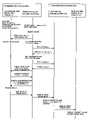
- FIG. 1schematically shows an embodiment of the present invention, namely, an outline of an image communication system.
- This systemincludes communication systems 80 A and 80 B and a server 90 which can communicate data with each other.
- the systems 80 A and 80 Bcan send and receive image data.
- the server 90has a printer 100 connected thereto.
- image data from the system 80 Ais once sent to the server 90 through a network.
- the image datais transmitted via the server 90 to the system 80 B.
- the data from the system 80 Acan be directly sent via the network to the system 80 B without using the server 90 .
- the image datais sent from the system 80 A to the system 80 B for convenience of explanation, it is to be understood that the image data may be sent from the system 80 B to the system 80 A. Both systems 80 A and 80 B can send and receive image data in this embodiment. However, it may also be possible that one of the systems is dedicated to transmission and the other one thereof to reception.
- the communication system 80 Aincludes a digital still camera 1 A and a portable (cellular) phone 40 A which can communicate data with each other. Although this embodiment uses radio waves to communicate data between the digital still camera 1 A and the portable phone 40 A, the data may be communicated via wire telecommunication.
- the communication system 80 Bsimilarly includes a digital still camera 1 B and a portable (cellular) phone 40 B.
- the digital still cameras 1 A and 1 B as well as the portable phones 40 A and 40 Bare respectively of the same configurations.
- FIG. 2shows an appearance of a rear side of the digital still camera 1 A.
- the digital still camera 1 Aincludes a group of switches 15 in a right-hand side of its upper surface.
- the switch group 15includes a shutter release button 2 , an erase or clear button 3 to issue an image erase or clear instruction, a setting button, an increment button 5 , a decrement button 6 , and a mode setting dial 7 (to set such modes as a setup mode, an image reproduction (playback) mode, a shooting mode and a communication mode).
- the digital still camera 1 Aincludes on its rear surface a display screen 9 of a liquid-crystal display device for displaying an image.
- the screen 9almost fully occupies the rear surface.
- the display screen 9includes an area 10 to display a mode currently selected, an area 11 to display a frame number of an image displayed, and an area 12 to indicate that the image being displayed on the screen 9 has been shot in a high-precision mode, a standard mode, or an economy mode in which image data is compressed with a higher compression ratio.
- the screen 9further includes an area to display the current “day and time”.
- the rear surface of the digital still camera 1 Afurther includes a power switch 8 in its upper section.
- the digital still camera 1 Aincludes a radio wave antenna on a left-side surface thereof (opposite to a side surface on the right-hand side in FIG. 2 ) to communicate data with the portable phone 40 A.
- FIG. 3shows in a block diagram an electric construction of the digital still camera 1 A.
- the digital still camera 1 Aincludes a central processing unit (CPU) 20 , a shooting lens 21 , a solid-state electronic imaging device 22 , an analog-to-digital (A/D) converter 23 , an image processing circuit 27 , a digital-to-analog (D/A) converter 30 , a display device 9 , a memory buffer 33 , a first compressor-expander (data compression/expansion circuit) 25 , a second compressor-expander (data compression/expansion circuit) 26 and a change (modification) processing circuit 24 .
- CPUcentral processing unit
- A/Danalog-to-digital
- D/Adigital-to-analog
- the CPU 20supervises overall operation of the digital still camera 1 A.
- the digital still camera 1 Aincludes a connector 28 .
- a memory card 35is detachably mounted on the connector 28 .
- the digital still camera 1 Aincludes a communication interface 29 to communicate data with the portable phone 40 A.
- the communication interface 29includes a radio wave antenna, not shown, to communicate data with the portable phone 40 A.
- the shooting lens 21produces an optically focused image of an object onto a light receiving surface of the imaging device 22 .
- the imaging device 22outputs a video signal representing the image to an A/D converter 23 .
- the A/D converter 23converts an analog video signal into digital image data.
- the digital image datais fed to the image processing circuit 27 .
- the image processing circuit 27conducts predetermined signal processing such as white-balance adjustment and gamma correction for the data received.
- Image data from the processing circuit 27is inputted to the D/A converter 30 and is again converted into an analog video signal.
- the signalis supplied to the display device 9 (this reference numeral 9 is used for the display and the display screen).
- the display device 9resultantly displays an image of the object.
- the image data of the objectis temporarily stored in the memory buffer 33 .
- the datais thereafter read from the buffer 33 to be fed to the image processing circuit 27 .
- the image datais compressed in the processing circuit 27 .
- the compressed image datais delivered via the connector 28 to the memory card 35 and is recorded on the memory card 35 .
- the image datais read from the memory card 35 and is fed to the first compressor-expander 25 .
- the image datais expanded by the circuit 25 and is inputted to the D/A converter 30 to be converted into analog video signal.
- the signalis delivered to the display device 9 and is displayed as a reproduced image on the display screen.
- the image datais read from the memory card 35 and is expanded in almost the same way as for the reproduction mode.
- the image data expandedis inputted to the change (modification) processing circuit 24 .
- the circuit 24re-sizes the data (reduces the image size, for example, by thinning out image elements and compressing resultant image data) to reduce a quantity of image data to be transmitted.
- the image data re-sizedis supplied to the communication interface 29 .
- the datais therefore transmitted from the digital still camera 1 A via the interface 29 to the portable phone 40 A.
- the image data transmitted from the portable phone 40 Ais received by the interface 29 , and received image data is fed via the connector 28 to the memory card 35 to be recorded thereon.
- the first compressor-expander 25has a variable compression ratio which can be changed by setting a parameter.
- the second compressor-expander 26compresses data in a compression procedure other than that of the first compressor-expander 25 .
- the digital still camera 1 Aalso includes an attribute register 31 and a power supply circuit 32 .
- the register 31stores information of attributes such as a camera type or model code and a maker name.
- the power supply 32powers respective constituent circuits of the digital still camera 1 A.
- FIG. 4shows an appearance of a front side of the portable phone 40 A.
- the portable phone 40 Aincludes in its upper end section an antenna 41 to communicate data with the digital still camera 1 A and to communicate data (to conducts a call) via a network with the portable phone 40 B and the server 100 .
- the portable phone 40 Aincludes in an upper section of its front surface a speaker 42 to produce sound and voice.
- the portable phone 40 Aincludes a liquid-crystal display screen 43 below the speaker 42 .
- the display screen 43includes an area 46 to indicate power remained in a battery of the portable phone 40 A, an area 47 to indicate degree of reception of radio waves by the portable phone 40 A, and an area 45 to indicate a menu (mode) currently set.
- the screen 43further includes an area 44 to display a thumb-nail image, a selection area 48 to display a selectable frame number of image and a selectable menu and so on.
- a cursor (frame) 49to indicate, for example, a frame number to be selected also appears on the screen 43 .
- a phone book button 51which is depressed by the user to display in the screen 43 a list of phone numbers stored (a telephone directory), a setting button 52 which is depressed by the user to issue a setting instruction, and a menu button 53 for the user to display a menu on the screen 43 .
- the button 54includes thereon an up arrow mark, a down arrow mark, a left arrow mark, and a right arrow mark.
- the usercan depress each arrow mark.
- the systemproduces a signal representing the depression of the arrow mark.
- the usercan also depress a central section 50 of the button 54 .
- an instruction indicating “determination of operation”is issued (this is therefore called “OK button”)
- the portable phone 40 Afurther includes a ten-key unit 58 below these buttons 55 to 57 .
- the front surface of the portable phone 40 Aincludes in its lowermost section a microphone 59 to receive sound and voice.
- FIG. 5shows in a block diagram an electric configuration of the portable phone 40 A.
- the portable phone 40 Aincludes a CPU 60 , a group of switches 67 , a modulator 73 , an A/D converter 74 , a communication buffer 63 , a communication circuit 64 , a D/A converter circuit 72 , a demodulator circuit 71 , an internal antenna 41 , and a communication circuit 62 .
- the CPU 60controls entire operation of the portable phone 40 A.
- the CPU 60is connected to a nonvolatile memory 65 to store telephone numbers, electronic mail addresses, and uniform resource locators (URL).
- a nonvolatile memory 65to store telephone numbers, electronic mail addresses, and uniform resource locators (URL).
- the CPU 60is connected to an external memory 66 to temporarily store various data.
- Sound received by the microphone 59is fed as an analog signal to the modulator 73 and modulated therein.
- the signal modulatedis fed to the A/D converter 74 to be converted by the A/D converter 74 into digital sound or audio data.
- the audio datais transmitted via the communication buffer 63 , the communication circuit 64 , and the internal antenna 41 to a communicating partner telephone.
- the audio or voice data sent from the partneris received via the antenna 41 by the communication circuit 64 .
- the voice datais delivered via the buffer 63 to the D/A converter 72 to be converted into an analog audio or voice signal.
- the signalis then demodulated by the demodulator 71 to be fed to the speaker 42 .
- the speaker 42resultantly produces sound.
- image data transmitted from the digital still camera 1 Ais received by the antenna 61 and is demodulated by the communication circuit 62 .
- Resultant image datais sent from the communication circuit 62 to be temporarily stored in the buffer 63 .
- the image datais fed from the buffer 63 to the communication circuit 64 .
- a 1.5 gigaherz (GHz) carrier waveis modulated according to the image data.
- Image data modulatedis delivered to the antenna 41 .
- the datais sent therefrom via a network to the server 90 or the portable phone 40 B.
- image data received via a network by the antenna 41is demodulated by the communication circuit 64 .
- the image datais sent from the circuit 64 to be temporarily stored in the buffer 63 .
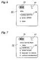
- FIGS. 6 to 9show examples of the display screen 43 of the portable phone 40 B.
- FIG. 6shows an example of a menu image.
- the usercan selects one of the services shown on the screen 43 , i.e., 1. Image service; 2. Music service; and 3. News.
- the cursor 49is displayed on the screen 43 .
- the up arrow markis depressed in the button 54 , the cursor moves upward.
- the down markis depressed, the cursor moves downward.
- the OK button 50depresses the OK button 50 while “image service” is being enclosed by the cursor 49 , the screen 43 changes to an image service menu shown in FIG. 7 .
- the image service menu on the screen 43 of FIG. 7includes 1. Print; 2. Image mail; 3. Photo upload; 4. Transmit data to camera; and 5. Instruct enlargement.
- Printindicates a service which is selected by the user to print an image by a printer 100 connected to a server 90 .
- Image mailis a service for the user to send image data to the communication system 80 B.
- Photo uploadis a service which is selected by the user to upload image data onto the server 90 .
- Transmit data to camerais a service for the user to send received image data to a digital still camera.
- Instruct enlargementis a service for the user to request a high-quality image.
- the screen 43changes to an image selection menu shown in FIG. 8 .
- the image of the selection menuincludes an area 48 to display a frame number of selectable image and an area 44 to display a thumb-nail image of an image identified by a frame number enclosed by the cursor 49 .
- the OK button 50is depressed, the image of a frame number enclosed by the cursor 49 is selected as a subject of transmission, that is, image data representing the image is to be transmitted.
- Selectable frame numbersare naturally beforehand sent from the digital still camera 1 A to the portable phone 40 A.
- FIG. 9shows in a flowchart a processing procedure of data communication between the communication systems 80 A and 80 B.
- a subjectis shot by the digital still camera 1 A and an image of the subject is presented on the display screen of the display device 9 .
- Image data representing the image of the subjectis compressed by the image processing circuit 27 and is recorded on the memory card 35 .
- the user of the portable phone 40 Aselects “2. Image mail” from the image service items and then inputs a phone number of the partner portable phone 40 B to which image data is to be sent.
- the portable phone 40 Ais connected for communication with the portable phone 40 B as the destination of the image data.
- the image data to be transmittedis selected as above.
- Data designating a frame number of image selected by the useris sent from the portable phone 40 A to the digital still camera 1 A.
- the digital still camera 1 Areceives the data of the frame number from the portable phone 40 A.
- Image data corresponding to the frame numberis read from the memory card 35 and is fed to the first compressor-expander 25 .
- the circuit 25expands the compressed image data.
- the resultant image datais temporarily stored in the memory buffer 33 of the digital still camera 1 A.
- the portable phone 40 Adetects occurrence of a re-size instruction. Data representing the re-size instruction is sent from the portable phone 40 A to the digital still camera 1 A.
- the digital still camera 1 AWhen the digital still camera 1 A receives the data of the re-size instruction, the data temporarily stored in the buffer 33 is read therefrom and is delivered to the change (modification) processing circuit 24 .
- the circuit 24re-sizes the image data to reduce the quantity thereof.
- Image data resultant from the re-sizingis fed to the first compressor-expander circuit 25 .
- the circuit 25changes a compression parameter to compress the image data with a compression ratio larger than that used when the image data is compressed and is recorded on the memory card 35 .
- the image data resized and compressed (resized image data)is sent from the digital still camera 1 A via the interface 29 to the portable phone 40 A.
- the portable phone 40 AWhen the portable phone 40 A receives the resized image data from the digital still camera 1 A, the data is then sent via a network to the portable phone 40 B on the receiver side.
- the portable phone 40 Btemporarily stores the re-sized image data in the communication buffer 63 .
- the re-sized image datais thereafter read from the communication buffer 63 to be fed to a display device of the portable phone 40 B.
- the display devicepresents an image of the re-sized image data on its display screen.
- the user of the portable phone 40 Bconfirms the re-sized image on the display screen and selects “4. Transmit data to camera” in the image service menu.
- the re-sized image datais then read from the communication buffer 63 to be sent to the digital still camera 1 B on the receiver side (the digital still camera 1 B is assigned with a particular identifier code and the image data is naturally sent to the digital still camera 1 B using the identifier code).
- the re-sized image dataWhen the re-sized image data is received by the digital still camera 1 B, the re-sized image data is fed to the display device. An image represented by the re-sized image data is displayed on the display screen of the display device. The re-sized image data is recorded in a memory card of the digital still camera 1 B.
- the image dataWhen image data is sent from the communication system 80 A to the communication system 80 B, the image data is re-sized by the digital still camera 1 A of the communication system 80 A to minimize the quantity of image data to be transmitted. Consequently, the transmission time of the image data is reduced. Since the re-sized image data is compressed with a compression ratio larger than that used when the image data is compressed to be recorded on the memory card 35 , the period of time required to send the image data is shortened.
- the re-sizing and the re-compression processing of the image dataare carried out by the digital still camera 1 A on the sender side in this embodiment, it is only necessary to execute at least either one of the re-sizing and the re-compression processing.
- the image dataseems to be sent from the portable phone 40 A on the sender side to the portable phone 40 B on the receiver side without using the server 90 , it is to be understood that the image data is transmitted from the portable phone 40 A via the server 90 to the portable phone 40 B. However, the image data may be actually sent from the portable phone 40 A directly to the portable phone 40 B without using the server 90 .
- FIG. 10shows a directory layout of the memory card of the digital still camera 1 B on the receiving side.
- the directoryincludes a root directory to manage all directories having a directory name “image”.
- a directory having a directory name “image”manages image data transmitted (received).
- Image data items (image files) managed with a sub-directory name under the directory having a directory name “image”are image data items transmitted (received) through one transmission.
- image files(with file names “IMAGE0001.JPG”, “IMAGE0002.JPG”, and the like) managed under a sub-directory name “DS309804-990501-0001” are image files transmitted through one transmission.
- a sub-directory namecomprises a type code (DS309804) of the digital still camera 1 A on the sender side, a transmission date (990501), and a directory number (0001). Attribute information stored in the attribute register 31 of the digital still camera 1 A is sent together with the image data. It is naturally possible that the type or model code is obtained from the attribute information and is used as an item of the sub-directory name.
- a telephone number of the portable phone 40 A having sent the image datamay be employed as a sub-directory name. By checking the sub-directory name, it is possible to determine the telephone number of the portable phone 40 A having sent the image data.
- FIG. 11shows a file layout of an image file (IMGE0001.JPG) recorded on a memory card of the digital still camera 1 B on the receiving side.
- IMGE0001.JPGimage file
- the image fileincludes a header and an image data recording area.
- the re-sized image data as aboveis recorded on the image data recording area.
- the headerincludes a header area to indicate a format of image data (a joint photographic coding experts group (JPEG) header area in this case), an image attribute information area, and thumb-nail data area.
- JPEGjoint photographic coding experts group
- the image attribute information areastores recording day and time, shooting conditions and communication history information.
- the communication history informationincludes a transmission date, a maker name of the portable phone having sent image data, a phone number of the portable phone having sent image data, and data indicating the number of pixels of image before the re-sizing.
- the thumb-nail data recording areaincludes a thumb-nail image header and thumb-nail image data.
- the change processing circuit 24re-sizes the data quantity of the image data for transmission in the embodiment, the image data quantity may be reduced by deleting low-order bits of the image data (by the so-called bit thinning-out). This processing will be executed by the circuit 24 .
- the first compressor-expander circuit 25compresses image data, which is recorded on the memory card 35 .
- the second compressor-expander circuit 26may compress the data. Even if the circuit 26 compresses the image data in a particular compression method, the circuit 25 compresses image data in a standard data compression method in an image data transmission phase. The receiver receives the image data compressed in such a standard method and hence can expand the image data received.
- the digital still camera 1 Amay be further provided with a switch to issue a re-size instruction. An image can be therefore re-sized without the re-size instruction from the portable phone 40 A. The re-sizing will be executed also by the change processing circuit 24 of the digital still camera 1 A.
- an image represented by image datais re-sized regardless of the communication speed of the network and then the image data re-sized is transmitted.
- the re-sizing ratiomay be changed according to the communication speed of the network.
- FIGS. 12 and 13show relationships between the communication speed and the re-sizing ratio for an image of 1280 horizontal pixels ⁇ 960 vertical pixels and an image of 2560 horizontal pixels ⁇ 1920 vertical pixels, respectively.
- FIG. 14shows in a flowchart a processing procedure to send image data from the communication system 80 A to the communication system 80 B.
- the re-sizing ratiois changed according to the data communication speed of the network in this processing procedure.
- the phone number of the portable phone 40 B of the receiving sideis inputted in the portable phone 40 A of the transmission side.
- the user of the portable phone 40 Aselects an image for transmission and then data indicating a frame number of the image selected is sent from the portable phone 40 A to the digital still camera 1 A.
- the digital still camera 1 Athe image data to be transmitted is expanded.
- the portable phone 40 A of the transmission sideis set to a highest communication speed, e.g. 2 Mbps and a reply request is sent from the portable phone 40 A of the transmission side to the portable phone 40 B of the receiving side.
- the portable phone 40 B of the receiving sidesends a normal replay to the portable phone 40 A. If the reception is not possible, no reply is sent from the portable phone 40 B of the receiving side to the portable phone 40 A of the transmission side. When a predetermined period of time lapses without any replay, a time-out is assumed. The portable phone 40 A of the transmission side recognizes that the image data cannot be sent at the communication speed requested.
- the communication speedis stepwise reduced to 384 kbps in this situation.
- the portable phone 40 A of the transmission sidesends again a reply request to the phone 40 B of the receiving side.
- the portable phone 40 Bcan receive image data at the communication speed of the replay request from the portable phone 40 A, the portable phone 40 B of the receiving side transmits a normal replay to the portable phone 40 A of the transmission side.
- the portable phone 40 Aselects the digital still camera 1 A and inquires the digital still camera 1 A of the number of pixels of an image for transmission.
- the digital still camera 1 Asends data of the number of pixels to the portable phone 40 A. Assume that an image of 2560 horizontal pixels ⁇ 1920 vertical pixels is selected.
- the portable phone 40 AHaving received the data, the portable phone 40 A sends a re-size instruction to the digital still camera 1 A according to the communication speed at which image data can be received by the portable phone 40 B of the receiving side. Since the communication speed is 384 kbps and the image selected includes 2560 horizontal pixels ⁇ 1920 vertical pixels in this embodiment, the re-size instruction from the portable phone 40 A to the digital still camera 1 A is determined by referencing FIG. 13 to reduce the number of pixels to one fourth for each of the horizontal and vertical directions.
- the digital still camera 1 Aaccordingly re-sizes the image data and sends the image data re-sized to the portable phone 40 A.
- the portable phone 40 Areceives the re-sized image data and then transmits the re-sized image data to the portable phone 40 B on the receiving side. Having received the re-sized data, the portable phone 40 B sends the re-sized image data to the digital still camera 1 B. The re-sized image data is then recorded on a memory card of the digital still camera 1 B as described above.
- FIG. 15shows in a flowchart of another embodiment of a communication procedure between the communication systems 80 A and 80 B.
- the re-sizing ratiois determined according to an instruction from the portable phone 40 B on the receiving side in the processing procedure of FIG. 15 .
- an image for transmissionis selected and data of a frame number of the image selected is sent from the portable phone 40 A to the digital still camera 1 A on the transmission side.
- the portable phone 40 Athereafter inquires the digital still camera 1 A of the number of pixels of the image selected.
- the digital still camera 1 Asends data representing the number of pixels, for example, 2560 horizontal pixels ⁇ 1920 vertical pixels, to the portable phone 40 A.
- the digital still camera 1 Atransmits data of a thumb-nail image corresponding to the selected image to the portable phone 40 A.
- the portable phone 40 A on the transmission sidesends the received thumb-nail image data to the portable phone 40 B on the receiving side.
- a thumb-nail image represented by the thumb-nail image datais displayed on the display screen of the portable phone 40 B.
- the uservisually checks the thumb-nail image on the screen to confirm the image presented by the image data transmitted. If it is desired that image data of an image having resolution higher than resolution of the thumb-nail image is recorded in the digital still camera 1 B on the receiving side, a request for enlargement is inputted to the portable phone 40 B (“Instruct enlargement” is selected as above; FIG. 7 ).
- the data of enlargement request inputtedis transmitted from the portable phone 40 B on the receiving side to the portable phone 40 A on the transmission side.
- the portable phone 40 AHaving received the enlargement request data, the portable phone 40 A sends a re-size instruction, for example, 1 ⁇ 8 in both of horizontal and vertical directions, to the digital still camera 1 A.
- a re-size instructionfor example, 1 ⁇ 8 in both of horizontal and vertical directions
- the image data of the selected imageis re-sized according to the re-size instruction.
- the digital still camera 1 Asends the image data resized (to 320 horizontal pixels ⁇ 240 vertical pixels) to the portable phone 40 A on the transmission side.
- the portable phone 40 Areceives the re-sized image data and then sends the re-sized image data to the portable phone 40 B of the receiving side.
- the portable phone 40 BWhen the portable phone 40 B receives the re-sized image data, the re-sized image data is delivered to the display. The image is displayed with the new resolution. If the new image displayed is not satisfactory, the user of the portable phone 40 B again inputs a request for enlargement.
- the enlargement requestis sent from the portable phone 40 B to the portable phone 40 A.
- the portable phone 40 Asends again a re-size instruction to the digital still camera 1 A on the transmission side.
- the re-size instructionimproves the resolution. For example, a re-size instruction to reduce pixels to 1 ⁇ 4 for the horizontal and vertical directions is sent to the digital still camera 1 A.
- the digital still camera 1 Are-sizes the image data according to the re-size instruction.
- the re-sized image datais sent from the digital still camera 1 A to the portable phone 40 A.
- the portable phone 40 Atransmits the re-sized image data to the portable phone 40 B.
- the re-sized image datais transferred to the display of the portable phone 40 B.
- the imageis displayed on the display screen with higher picture quality.
- the request for enlargementis sent to the portable phone 40 A to repeatedly execute the re-sizing.
- a transmission instructionis inputted to the portable phone 40 B (“Transmit data to camera” is selected; FIG. 7 ).
- the portable phone 40 Bsends the re-sized image data to the digital still camera 1 B.
- the re-sized image datais then recorded on a memory card of the digital still camera 1 B.
- the user on the image data receiving sidecan indicate the re-sizing ratio, namely, image quality.
- FIG. 16shows in a flow chart another embodiment of the communication procedure between the communication systems 80 A and 80 B. Description will be given of discrepancy between FIG. 14 and FIG. 16 .
- the initial communication speedis set to 384 kbps (2 Mbps in FIG. 14 ).
- the portable phone 40 A on the transmission sidetransmits a re-size instruction to the digital still camera 1 A on the transmission side.
- the digital still camera 1 Areceives the re-size instruction and then calculates the number of pixels of the image re-sized.
- the number of pixels of the re-sized imageis compared with that of pixels of a thumb-nail image of the image selected. It is judged whether the re-sized image data or the thumb-nail image data is transmitted according to a result of the comparison as follows.
- the thumb-nail image datais transmitted to the portable phone 40 B on the receiving side through the portable phone 40 A. Specifically, when the following expressions are satisfied, the thumb-nail image data is transmitted. 80 ⁇ Noh ⁇ 200 (1) 60 ⁇ Nov ⁇ 180 (2) where, Noh indicates the number of horizontal pixels of the re-sized image and Nov is the number of vertical pixels of the re-sized image.
- the image selectedincludes 1280 horizontal pixels and 960 vertical pixels and the re-size instruction indicates to reduce the pixels to 1 ⁇ 8 in the horizontal and vertical directions.
- FIGS. 17 to 23show still another embodiment.
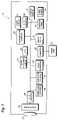
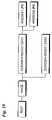
- FIG. 17shows in a block diagram an electronic construction of the server 90 and the printer 100 .
- the server 90includes a CPU 91 to control overall operation of the server 90 and a hard disk 94 to store a predetermined program and other data.
- the server 90further includes an RAM 92 to temporarily store data, an ROM 93 to store a basic input/output system (BIOS), and an interface 95 for data communication.
- BIOSbasic input/output system
- the server 90is connected to a radio wave receiver 96 to communicate data with the portable phones 40 A and 40 B.
- the server 90thus configured is connected to the printer 100 .
- the printer 100includes a CPU 101 to supervise entire operation thereof.
- the printer 100includes an interface 102 to communicate data with the server 90 .
- the printer 100further includes an RAM 106 to temporarily store data, a printer attribute ROM 107 to store printer attribute information, a form (paper) feeder 103 , a print engine 104 , and a printout classifying device 105 .
- the hard disk 94includes an area to store image files sent from the portable phones 40 A and 40 B, an area to store user information, and a program area.
- the user informationincludes data items respectively indicating a name of a user authorized to access the server 90 , a phone number of the user, an address of the user, and a total charge when the printer 100 is used to produce printout.
- the data items respectively of the user name, the phone number, and the addressare registered thereto in advance.
- FIG. 19shows examples of information printer attributes stored in the printer attribute ROM 107 of the printer 100 .
- FIGS. 20 to 22show examples of the display screen 43 of a portable phone when the user orders copies of images to be produced by the printer 100 .
- Image servicein the menu image shown in FIG. 6 .
- an image service menuappears on the screen of the portable phone as shown in FIG. 20 .
- the userselects “1. Print” from the image service menu when the user desires to order print of image.
- the display screen of the portable phonechanges to an image selection screen shown in FIG. 21 .
- the userencloses a frame number of an image to be printed by the cursor 49 and inputs the number of copies thereof by the ten-key unit of the portable phone.
- the number of copiesis displayed on a number display area 50 .
- the screen 43 of the portable phonechanges to a confirmation screen shown in FIG. 22 .
- FIG. 23shows in a flowchart a communication procedure between the communication system 80 A, the server 90 and the printer 100 .
- the portable phone 40 A of the communication system 80 A on the transmission sideinitiates connection to the server 90 .
- the server 90issues an enquiry for printer attributes to the printer 100 .
- printer attribute ROM 107When the enquiry for printer attributes is received by the printer 100 , data representing printer attributes is obtained from the printer attribute ROM 107 and is sent to the server 90 .
- the server 90Having received the printer attribute data, the server 90 sends the data to the portable phone 40 A.
- the digital still camera 1 Aexpands image data associated with images respectively corresponding to the frame numbers.
- the portable phone 40 Agenerates, according to the received printer attributes, a gradation change instruction to set image data suitable for the printout by the printer 100 .
- the portable phone 40 Asends data representing the gradation change instruction to the digital still camera 1 A.
- the change processing circuit 24conducts a gradation change for the image data expanded. If necessary, a format conversion, a color space change and the like are achieved for the image data format so that the printer 100 appropriately processes the image data received.
- the image data for which the gradation change has been conductedis sent from the digital still camera 1 A to the portable phone 40 A.
- the server 90transfers the image data to the printer 100 .
- the printer 100produces copies of image according to the specified number.
- the printout classifying device 105sorts the obtained copies for each printout order.
- the server 90receives the data of the phone number, the user information stored is searched for an address of the pertinent user. The copies produced are then delivered by mail to the address of the user. It may also possible that the server 90 sends the address of the user having ordered the printout to the printer 100 . Having received the address, the printer prints the address on an envelope.
- the printout classifying device 105therefore sorts the envelopes together with printouts for each order of printout.
Landscapes
- Engineering & Computer Science (AREA)
- Multimedia (AREA)
- Signal Processing (AREA)
- Human Computer Interaction (AREA)
- Facsimiles In General (AREA)
- Mobile Radio Communication Systems (AREA)
- Editing Of Facsimile Originals (AREA)
- Two-Way Televisions, Distribution Of Moving Picture Or The Like (AREA)
- Compression Of Band Width Or Redundancy In Fax (AREA)
- Telephonic Communication Services (AREA)
- Studio Devices (AREA)
- Television Signal Processing For Recording (AREA)
Abstract
Description
80<Noh<200 (1)
60<Nov<180 (2)
where, Noh indicates the number of horizontal pixels of the re-sized image and Nov is the number of vertical pixels of the re-sized image.
Claims (3)
Priority Applications (1)
| Application Number | Priority Date | Filing Date | Title |
|---|---|---|---|
| US11/350,039US7605846B2 (en) | 1999-07-30 | 2006-02-09 | Image communication system and an apparatus for and a method of processing an image |
Applications Claiming Priority (4)
| Application Number | Priority Date | Filing Date | Title |
|---|---|---|---|
| JP21605899AJP4039775B2 (en) | 1999-07-30 | 1999-07-30 | Image communication system, digital camera constituting the system, and operation control method thereof |
| JPJP11-216058 | 1999-07-30 | ||
| US09/628,546US7027084B1 (en) | 1999-07-30 | 2000-07-28 | Image communication system and an apparatus for and a method of processing an image |
| US11/350,039US7605846B2 (en) | 1999-07-30 | 2006-02-09 | Image communication system and an apparatus for and a method of processing an image |
Related Parent Applications (1)
| Application Number | Title | Priority Date | Filing Date |
|---|---|---|---|
| US09/628,546DivisionUS7027084B1 (en) | 1999-07-30 | 2000-07-28 | Image communication system and an apparatus for and a method of processing an image |
Publications (2)
| Publication Number | Publication Date |
|---|---|
| US20060125927A1 US20060125927A1 (en) | 2006-06-15 |
| US7605846B2true US7605846B2 (en) | 2009-10-20 |
Family
ID=16682626
Family Applications (2)
| Application Number | Title | Priority Date | Filing Date |
|---|---|---|---|
| US09/628,546Expired - LifetimeUS7027084B1 (en) | 1999-07-30 | 2000-07-28 | Image communication system and an apparatus for and a method of processing an image |
| US11/350,039Expired - Fee RelatedUS7605846B2 (en) | 1999-07-30 | 2006-02-09 | Image communication system and an apparatus for and a method of processing an image |
Family Applications Before (1)
| Application Number | Title | Priority Date | Filing Date |
|---|---|---|---|
| US09/628,546Expired - LifetimeUS7027084B1 (en) | 1999-07-30 | 2000-07-28 | Image communication system and an apparatus for and a method of processing an image |
Country Status (2)
| Country | Link |
|---|---|
| US (2) | US7027084B1 (en) |
| JP (1) | JP4039775B2 (en) |
Cited By (32)
| Publication number | Priority date | Publication date | Assignee | Title |
|---|---|---|---|---|
| US20070210932A1 (en)* | 2006-03-09 | 2007-09-13 | Fujifilm Corporation | Remote control device, method and system |
| US20090019392A1 (en)* | 2007-07-11 | 2009-01-15 | Sony Corporation | Content transmission device, content transmission method, and content transmission program |
| CN102143353A (en)* | 2010-02-02 | 2011-08-03 | 捷达世软件(深圳)有限公司 | Method for real-time collecting video |
| US20120068857A1 (en)* | 2010-09-22 | 2012-03-22 | Apple Inc. | Configurable remote control |
| US9253340B2 (en) | 2011-11-11 | 2016-02-02 | Intellectual Ventures Fund 83 Llc | Wireless camera with image sharing prioritization |
| US9620312B2 (en) | 2013-08-09 | 2017-04-11 | Apple Inc. | Tactile switch for an electronic device |
| US9753436B2 (en) | 2013-06-11 | 2017-09-05 | Apple Inc. | Rotary input mechanism for an electronic device |
| US9891651B2 (en) | 2016-02-27 | 2018-02-13 | Apple Inc. | Rotatable input mechanism having adjustable output |
| US9952558B2 (en) | 2015-03-08 | 2018-04-24 | Apple Inc. | Compressible seal for rotatable and translatable input mechanisms |
| US10019097B2 (en) | 2016-07-25 | 2018-07-10 | Apple Inc. | Force-detecting input structure |
| US10018966B2 (en) | 2015-04-24 | 2018-07-10 | Apple Inc. | Cover member for an input mechanism of an electronic device |
| US10048802B2 (en) | 2014-02-12 | 2018-08-14 | Apple Inc. | Rejection of false turns of rotary inputs for electronic devices |
| US10055030B2 (en) | 2013-05-17 | 2018-08-21 | Apple Inc. | Dynamic visual indications for input devices |
| US10061399B2 (en) | 2016-07-15 | 2018-08-28 | Apple Inc. | Capacitive gap sensor ring for an input device |
| US10145711B2 (en) | 2015-03-05 | 2018-12-04 | Apple Inc. | Optical encoder with direction-dependent optical properties having an optically anisotropic region to produce a first and a second light distribution |
| US10190891B1 (en) | 2014-07-16 | 2019-01-29 | Apple Inc. | Optical encoder for detecting rotational and axial movement |
| US10551798B1 (en) | 2016-05-17 | 2020-02-04 | Apple Inc. | Rotatable crown for an electronic device |
| US10599101B2 (en) | 2014-09-02 | 2020-03-24 | Apple Inc. | Wearable electronic device |
| US10664074B2 (en) | 2017-06-19 | 2020-05-26 | Apple Inc. | Contact-sensitive crown for an electronic watch |
| US10962935B1 (en) | 2017-07-18 | 2021-03-30 | Apple Inc. | Tri-axis force sensor |
| US11181863B2 (en) | 2018-08-24 | 2021-11-23 | Apple Inc. | Conductive cap for watch crown |
| US11194298B2 (en) | 2018-08-30 | 2021-12-07 | Apple Inc. | Crown assembly for an electronic watch |
| US11194299B1 (en) | 2019-02-12 | 2021-12-07 | Apple Inc. | Variable frictional feedback device for a digital crown of an electronic watch |
| US11269376B2 (en) | 2020-06-11 | 2022-03-08 | Apple Inc. | Electronic device |
| US11360440B2 (en) | 2018-06-25 | 2022-06-14 | Apple Inc. | Crown for an electronic watch |
| US11550268B2 (en) | 2020-06-02 | 2023-01-10 | Apple Inc. | Switch module for electronic crown assembly |
| US11561515B2 (en) | 2018-08-02 | 2023-01-24 | Apple Inc. | Crown for an electronic watch |
| US11796968B2 (en) | 2018-08-30 | 2023-10-24 | Apple Inc. | Crown assembly for an electronic watch |
| US11796961B2 (en) | 2018-08-24 | 2023-10-24 | Apple Inc. | Conductive cap for watch crown |
| US12092996B2 (en) | 2021-07-16 | 2024-09-17 | Apple Inc. | Laser-based rotation sensor for a crown of an electronic watch |
| US12189347B2 (en) | 2022-06-14 | 2025-01-07 | Apple Inc. | Rotation sensor for a crown of an electronic watch |
| US12259690B2 (en) | 2018-08-24 | 2025-03-25 | Apple Inc. | Watch crown having a conductive surface |
Families Citing this family (59)
| Publication number | Priority date | Publication date | Assignee | Title |
|---|---|---|---|---|
| US6701845B2 (en)* | 2000-03-17 | 2004-03-09 | Nikon Corporation & Nikon Technologies Inc. | Print system and handy phone |
| WO2001091452A1 (en)* | 2000-05-26 | 2001-11-29 | Craftec Co., Ltd. | Image processing apparatus, image processing method, image processing system and information recorded medium |
| EP1191781A3 (en)* | 2000-09-25 | 2004-10-06 | Canon Kabushiki Kaisha | Image apparatus |
| JP4032210B2 (en)* | 2001-01-30 | 2008-01-16 | 富士フイルム株式会社 | Mobile device, image transmission system, and image transmission method |
| JP2002354329A (en)* | 2001-05-30 | 2002-12-06 | Minolta Co Ltd | Photographing device and photographing system |
| JP4919545B2 (en)* | 2001-06-28 | 2012-04-18 | パナソニック株式会社 | Data transmission system and photographing apparatus |
| JP4551594B2 (en)* | 2001-09-07 | 2010-09-29 | キヤノン株式会社 | Imaging apparatus, control method thereof, and computer program |
| GB0124323D0 (en) | 2001-10-10 | 2001-11-28 | Nokia Corp | Setting mode of communication |
| JP2003188801A (en)* | 2001-12-19 | 2003-07-04 | Nec Corp | Mobile phone terminal with videophone function |
| US7764308B2 (en) | 2002-05-27 | 2010-07-27 | Nikon Corporation | Image transmission system, image relay apparatus, and electronic image device |
| JP3993027B2 (en)* | 2002-06-04 | 2007-10-17 | 富士フイルム株式会社 | Digital camera and photographing system |
| JP2004032372A (en)* | 2002-06-26 | 2004-01-29 | Fuji Photo Film Co Ltd | Image data processing method, portable terminal device and program |
| JP2004040548A (en)* | 2002-07-04 | 2004-02-05 | Minolta Co Ltd | Image pickup device |
| JP3941624B2 (en)* | 2002-07-30 | 2007-07-04 | コニカミノルタビジネステクノロジーズ株式会社 | File storage device |
| JP4112394B2 (en)* | 2003-02-12 | 2008-07-02 | 株式会社リコー | Image processing device |
| US7844597B2 (en)* | 2003-09-15 | 2010-11-30 | Nokia Corporation | Modifying a database comprising image fields |
| TWM253170U (en)* | 2004-02-10 | 2004-12-11 | Jiun-Bei Chang | Interface device of detached and externally connected camera lens |
| US7398316B2 (en)* | 2004-02-27 | 2008-07-08 | Nokia Corporation | Method and apparatus for keyhole video frame transmission during a communication session |
| JP4619051B2 (en) | 2004-07-01 | 2011-01-26 | 株式会社リコー | Printing system, printing apparatus, imaging apparatus, printing method, and image transmission method |
| US7623155B2 (en)* | 2004-09-29 | 2009-11-24 | Kelliher Christopher R | GPS enhanced camera for transmitting real-time trail data over a satellite/cellular communication channel |
| FR2878392A1 (en)* | 2004-10-25 | 2006-05-26 | Cit Alcatel | METHOD OF EXCHANGING INFORMATION BETWEEN A MOBILE TERMINAL AND A SERVER |
| KR100603576B1 (en)* | 2004-12-06 | 2006-07-24 | 삼성전자주식회사 | Video signal transmission system between heterogeneous terminals and method thereof |
| KR100608835B1 (en)* | 2004-12-09 | 2006-08-08 | 엘지전자 주식회사 | Image transmission method of mobile terminal |
| US20060132836A1 (en)* | 2004-12-21 | 2006-06-22 | Coyne Christopher R | Method and apparatus for re-sizing image data |
| US20060174203A1 (en) | 2005-01-31 | 2006-08-03 | Searete Llc, A Limited Liability Corporation Of The State Of Delaware | Viewfinder for shared image device |
| US8606383B2 (en) | 2005-01-31 | 2013-12-10 | The Invention Science Fund I, Llc | Audio sharing |
| US20060171603A1 (en)* | 2005-01-31 | 2006-08-03 | Searete Llc, A Limited Liability Corporation Of The State Of Delaware | Resampling of transformed shared image techniques |
| US20060187228A1 (en)* | 2005-01-31 | 2006-08-24 | Searete Llc, A Limited Liability Corporation Of The State Of Delaware | Sharing including peripheral shared image device |
| US20060173972A1 (en)* | 2005-01-31 | 2006-08-03 | Searete Llc, A Limited Liability Corporation Of The State Of Delaware | Audio sharing |
| US7876357B2 (en) | 2005-01-31 | 2011-01-25 | The Invention Science Fund I, Llc | Estimating shared image device operational capabilities or resources |
| US9489717B2 (en) | 2005-01-31 | 2016-11-08 | Invention Science Fund I, Llc | Shared image device |
| US20060170956A1 (en)* | 2005-01-31 | 2006-08-03 | Jung Edward K | Shared image devices |
| US8902320B2 (en) | 2005-01-31 | 2014-12-02 | The Invention Science Fund I, Llc | Shared image device synchronization or designation |
| US9082456B2 (en) | 2005-01-31 | 2015-07-14 | The Invention Science Fund I Llc | Shared image device designation |
| US7920169B2 (en) | 2005-01-31 | 2011-04-05 | Invention Science Fund I, Llc | Proximity of shared image devices |
| US9124729B2 (en) | 2005-01-31 | 2015-09-01 | The Invention Science Fund I, Llc | Shared image device synchronization or designation |
| US9910341B2 (en) | 2005-01-31 | 2018-03-06 | The Invention Science Fund I, Llc | Shared image device designation |
| US20060187227A1 (en)* | 2005-01-31 | 2006-08-24 | Jung Edward K | Storage aspects for imaging device |
| US20060190968A1 (en)* | 2005-01-31 | 2006-08-24 | Searete Llc, A Limited Corporation Of The State Of The State Of Delaware | Sharing between shared audio devices |
| US20060285150A1 (en)* | 2005-01-31 | 2006-12-21 | Searete Llc, A Limited Liability Corporation Of The State Of Delaware | Regional proximity for shared image device(s) |
| US9001215B2 (en) | 2005-06-02 | 2015-04-07 | The Invention Science Fund I, Llc | Estimating shared image device operational capabilities or resources |
| US10003762B2 (en) | 2005-04-26 | 2018-06-19 | Invention Science Fund I, Llc | Shared image devices |
| US9819490B2 (en) | 2005-05-04 | 2017-11-14 | Invention Science Fund I, Llc | Regional proximity for shared image device(s) |
| JP2007041882A (en)* | 2005-08-03 | 2007-02-15 | Noritsu Koki Co Ltd | Photo print ordering program |
| US20070109417A1 (en)* | 2005-11-16 | 2007-05-17 | Per Hyttfors | Methods, devices and computer program products for remote control of an image capturing device |
| JP4847161B2 (en)* | 2006-03-02 | 2011-12-28 | キヤノン株式会社 | Image transmitting apparatus and imaging apparatus |
| KR100823267B1 (en)* | 2006-04-13 | 2008-04-21 | 삼성전자주식회사 | Full printing method and system by device |
| KR20080006126A (en)* | 2006-07-11 | 2008-01-16 | 삼성전자주식회사 | Photographing device capable of wireless transmission and control method |
| JP2008271151A (en) | 2007-04-19 | 2008-11-06 | Sony Corp | Radio communication system, radio communication apparatus, program, and radio communication method |
| EP2007128A1 (en) | 2007-05-29 | 2008-12-24 | Research In Motion Limited | System and method for resizing images prior to upload |
| US8068698B2 (en)* | 2007-05-29 | 2011-11-29 | Research In Motion Limited | System and method for resizing images prior to upload |
| US20080297585A1 (en)* | 2007-05-29 | 2008-12-04 | Ascalade Communications Inc. | Integrated cordless voice/video ip phone system |
| US8982223B2 (en)* | 2011-03-30 | 2015-03-17 | Panasonic Intellectual Property Management Co., Ltd. | Image sending apparatus, image recording apparatus and image recording method using identification information relating reduced image data with original image data |
| JP5893338B2 (en)* | 2011-10-25 | 2016-03-23 | キヤノン株式会社 | Image processing apparatus, image processing method, and program |
| KR20140090297A (en) | 2012-12-20 | 2014-07-17 | 삼성전자주식회사 | Image forming method and apparatus of using near field communication |
| US9667851B2 (en)* | 2013-01-24 | 2017-05-30 | Nikon Corporation | Camera with communication unit that communicates with external device |
| WO2015060485A1 (en)* | 2013-10-25 | 2015-04-30 | Lg Electronics Inc. | Image display apparatus and method of operating the same |
| EP3080976B1 (en) | 2013-12-09 | 2020-07-08 | Sony Corporation | A methof for sending a picture in an electronic device and such a device |
| JP6395522B2 (en)* | 2014-09-03 | 2018-09-26 | キヤノン株式会社 | COMMUNICATION DEVICE, COMMUNICATION DEVICE CONTROL METHOD, PROGRAM |
Citations (16)
| Publication number | Priority date | Publication date | Assignee | Title |
|---|---|---|---|---|
| JPH0575871A (en) | 1991-09-17 | 1993-03-26 | Canon Inc | Picture processor |
| US5502727A (en)* | 1993-04-20 | 1996-03-26 | At&T Corp. | Image and audio communication system having graphical annotation capability |
| JPH08237490A (en) | 1995-02-24 | 1996-09-13 | Fuji Photo Film Co Ltd | Image data transmission system and image data transmission method |
| US5666159A (en) | 1995-04-24 | 1997-09-09 | Eastman Kodak Company | Electronic camera system with programmable transmission capability |
| JPH09307794A (en) | 1996-05-10 | 1997-11-28 | Ricoh Co Ltd | Portable image transfer system |
| JPH09322114A (en) | 1996-03-27 | 1997-12-12 | Fuji Photo Film Co Ltd | Printing system and camera |
| US5734415A (en) | 1994-12-24 | 1998-03-31 | Samsung Electronics Co., Ltd. | Screen processing circuit and method of video phone using picture-in-picture function |
| US5737491A (en) | 1996-06-28 | 1998-04-07 | Eastman Kodak Company | Electronic imaging system capable of image capture, local wireless transmission and voice recognition |
| US5760824A (en) | 1995-12-29 | 1998-06-02 | Lucent Technologies Inc. | Multimedia telephone having wireless camera and television module and method of operation thereof |
| JPH10164483A (en) | 1996-12-04 | 1998-06-19 | Aqueous Res:Kk | Image data storage device |
| JPH10304231A (en) | 1997-04-30 | 1998-11-13 | Canon Inc | Portable electronic device, image processing method, imaging device, and computer-readable recording medium |
| JPH1146331A (en) | 1997-05-26 | 1999-02-16 | Seiko Epson Corp | Digital camera and printing system |
| JPH11177518A (en) | 1997-12-12 | 1999-07-02 | Kokusai Electric Co Ltd | Data communication device |
| US6104430A (en)* | 1994-09-28 | 2000-08-15 | Ricoh Company, Ltd. | Digital electronic still camera which receives an input/output control program through a detachable communication interface card |
| US6177950B1 (en) | 1996-01-17 | 2001-01-23 | Avt Audio Visual | Multifunctional portable telephone |
| US6380967B1 (en)* | 1996-12-07 | 2002-04-30 | Frank Sacca | System to capture, store, and retrieve composite video for transmission over telephone lines |
- 1999
- 1999-07-30JPJP21605899Apatent/JP4039775B2/ennot_activeExpired - Lifetime
- 2000
- 2000-07-28USUS09/628,546patent/US7027084B1/ennot_activeExpired - Lifetime
- 2006
- 2006-02-09USUS11/350,039patent/US7605846B2/ennot_activeExpired - Fee Related
Patent Citations (17)
| Publication number | Priority date | Publication date | Assignee | Title |
|---|---|---|---|---|
| JPH0575871A (en) | 1991-09-17 | 1993-03-26 | Canon Inc | Picture processor |
| US5502727A (en)* | 1993-04-20 | 1996-03-26 | At&T Corp. | Image and audio communication system having graphical annotation capability |
| US6104430A (en)* | 1994-09-28 | 2000-08-15 | Ricoh Company, Ltd. | Digital electronic still camera which receives an input/output control program through a detachable communication interface card |
| US5734415A (en) | 1994-12-24 | 1998-03-31 | Samsung Electronics Co., Ltd. | Screen processing circuit and method of video phone using picture-in-picture function |
| JPH08237490A (en) | 1995-02-24 | 1996-09-13 | Fuji Photo Film Co Ltd | Image data transmission system and image data transmission method |
| US5666159A (en) | 1995-04-24 | 1997-09-09 | Eastman Kodak Company | Electronic camera system with programmable transmission capability |
| US5760824A (en) | 1995-12-29 | 1998-06-02 | Lucent Technologies Inc. | Multimedia telephone having wireless camera and television module and method of operation thereof |
| US6177950B1 (en) | 1996-01-17 | 2001-01-23 | Avt Audio Visual | Multifunctional portable telephone |
| JPH09322114A (en) | 1996-03-27 | 1997-12-12 | Fuji Photo Film Co Ltd | Printing system and camera |
| JPH09307794A (en) | 1996-05-10 | 1997-11-28 | Ricoh Co Ltd | Portable image transfer system |
| US5737491A (en) | 1996-06-28 | 1998-04-07 | Eastman Kodak Company | Electronic imaging system capable of image capture, local wireless transmission and voice recognition |
| JPH10164483A (en) | 1996-12-04 | 1998-06-19 | Aqueous Res:Kk | Image data storage device |
| US6380967B1 (en)* | 1996-12-07 | 2002-04-30 | Frank Sacca | System to capture, store, and retrieve composite video for transmission over telephone lines |
| JPH10304231A (en) | 1997-04-30 | 1998-11-13 | Canon Inc | Portable electronic device, image processing method, imaging device, and computer-readable recording medium |
| JPH1146331A (en) | 1997-05-26 | 1999-02-16 | Seiko Epson Corp | Digital camera and printing system |
| US6618553B1 (en)* | 1997-05-26 | 2003-09-09 | Seiko Epson Corporation | Digital camera and printing system |
| JPH11177518A (en) | 1997-12-12 | 1999-07-02 | Kokusai Electric Co Ltd | Data communication device |
Cited By (103)
| Publication number | Priority date | Publication date | Assignee | Title |
|---|---|---|---|---|
| US7710456B2 (en)* | 2006-03-09 | 2010-05-04 | Fujifilm Corporation | Remote control device, method and system |
| US20100149355A1 (en)* | 2006-03-09 | 2010-06-17 | Fujifilm Corporation | Remote control device, method and system |
| US7907181B2 (en) | 2006-03-09 | 2011-03-15 | Fujifilm Corporation | Remote control device, method and system |
| US20070210932A1 (en)* | 2006-03-09 | 2007-09-13 | Fujifilm Corporation | Remote control device, method and system |
| US9613063B2 (en)* | 2007-07-11 | 2017-04-04 | Sony Corporation | Content transmission device, content transmission method, and content transmission program |
| US20090019392A1 (en)* | 2007-07-11 | 2009-01-15 | Sony Corporation | Content transmission device, content transmission method, and content transmission program |
| US8477196B2 (en)* | 2010-02-02 | 2013-07-02 | GDS Software (ShenZhen) Co., Ltd | Mobile device and method for video recording |
| US20110187872A1 (en)* | 2010-02-02 | 2011-08-04 | GDS Software (ShenZhen) Co., Ltd | Mobile device and method for video recording |
| CN102143353A (en)* | 2010-02-02 | 2011-08-03 | 捷达世软件(深圳)有限公司 | Method for real-time collecting video |
| US20120068857A1 (en)* | 2010-09-22 | 2012-03-22 | Apple Inc. | Configurable remote control |
| US9253340B2 (en) | 2011-11-11 | 2016-02-02 | Intellectual Ventures Fund 83 Llc | Wireless camera with image sharing prioritization |
| US10055030B2 (en) | 2013-05-17 | 2018-08-21 | Apple Inc. | Dynamic visual indications for input devices |
| US10795460B2 (en) | 2013-05-17 | 2020-10-06 | Apple Inc. | Dynamic visual indications for input devices |
| US11353969B2 (en) | 2013-05-17 | 2022-06-07 | Apple Inc. | Dynamic visual indications for input devices |
| US11531306B2 (en) | 2013-06-11 | 2022-12-20 | Apple Inc. | Rotary input mechanism for an electronic device |
| US9753436B2 (en) | 2013-06-11 | 2017-09-05 | Apple Inc. | Rotary input mechanism for an electronic device |
| US10234828B2 (en) | 2013-06-11 | 2019-03-19 | Apple Inc. | Rotary input mechanism for an electronic device |
| US9886006B2 (en) | 2013-06-11 | 2018-02-06 | Apple Inc. | Rotary input mechanism for an electronic device |
| US10331082B2 (en) | 2013-08-09 | 2019-06-25 | Apple Inc. | Tactile switch for an electronic device |
| US9836025B2 (en) | 2013-08-09 | 2017-12-05 | Apple Inc. | Tactile switch for an electronic device |
| US9620312B2 (en) | 2013-08-09 | 2017-04-11 | Apple Inc. | Tactile switch for an electronic device |
| US11886149B2 (en) | 2013-08-09 | 2024-01-30 | Apple Inc. | Tactile switch for an electronic device |
| US10732571B2 (en) | 2013-08-09 | 2020-08-04 | Apple Inc. | Tactile switch for an electronic device |
| US10962930B2 (en) | 2013-08-09 | 2021-03-30 | Apple Inc. | Tactile switch for an electronic device |
| US12181840B2 (en) | 2013-08-09 | 2024-12-31 | Apple Inc. | Tactile switch for an electronic device |
| US9627163B2 (en) | 2013-08-09 | 2017-04-18 | Apple Inc. | Tactile switch for an electronic device |
| US9971305B2 (en) | 2013-08-09 | 2018-05-15 | Apple Inc. | Tactile switch for an electronic device |
| US10175652B2 (en) | 2013-08-09 | 2019-01-08 | Apple Inc. | Tactile switch for an electronic device |
| US10331081B2 (en) | 2013-08-09 | 2019-06-25 | Apple Inc. | Tactile switch for an electronic device |
| US10216147B2 (en) | 2013-08-09 | 2019-02-26 | Apple Inc. | Tactile switch for an electronic device |
| US9709956B1 (en) | 2013-08-09 | 2017-07-18 | Apple Inc. | Tactile switch for an electronic device |
| US12307047B2 (en) | 2014-02-12 | 2025-05-20 | Apple Inc. | Rejection of false turns of rotary inputs for electronic devices |
| US10613685B2 (en) | 2014-02-12 | 2020-04-07 | Apple Inc. | Rejection of false turns of rotary inputs for electronic devices |
| US10222909B2 (en) | 2014-02-12 | 2019-03-05 | Apple Inc. | Rejection of false turns of rotary inputs for electronic devices |
| US10884549B2 (en) | 2014-02-12 | 2021-01-05 | Apple Inc. | Rejection of false turns of rotary inputs for electronic devices |
| US12045416B2 (en) | 2014-02-12 | 2024-07-23 | Apple Inc. | Rejection of false turns of rotary inputs for electronic devices |
| US11669205B2 (en) | 2014-02-12 | 2023-06-06 | Apple Inc. | Rejection of false turns of rotary inputs for electronic devices |
| US11347351B2 (en) | 2014-02-12 | 2022-05-31 | Apple Inc. | Rejection of false turns of rotary inputs for electronic devices |
| US10048802B2 (en) | 2014-02-12 | 2018-08-14 | Apple Inc. | Rejection of false turns of rotary inputs for electronic devices |
| US10190891B1 (en) | 2014-07-16 | 2019-01-29 | Apple Inc. | Optical encoder for detecting rotational and axial movement |
| US11015960B2 (en) | 2014-07-16 | 2021-05-25 | Apple Inc. | Optical encoder for detecting crown movement |
| US11474483B2 (en) | 2014-09-02 | 2022-10-18 | Apple Inc. | Wearable electronic device |
| US10613485B2 (en) | 2014-09-02 | 2020-04-07 | Apple Inc. | Wearable electronic device |
| US10599101B2 (en) | 2014-09-02 | 2020-03-24 | Apple Inc. | Wearable electronic device |
| US10620591B2 (en) | 2014-09-02 | 2020-04-14 | Apple Inc. | Wearable electronic device |
| US10627783B2 (en) | 2014-09-02 | 2020-04-21 | Apple Inc. | Wearable electronic device |
| US11221590B2 (en) | 2014-09-02 | 2022-01-11 | Apple Inc. | Wearable electronic device |
| US10942491B2 (en) | 2014-09-02 | 2021-03-09 | Apple Inc. | Wearable electronic device |
| US11762342B2 (en) | 2014-09-02 | 2023-09-19 | Apple Inc. | Wearable electronic device |
| US11567457B2 (en) | 2014-09-02 | 2023-01-31 | Apple Inc. | Wearable electronic device |
| US10145711B2 (en) | 2015-03-05 | 2018-12-04 | Apple Inc. | Optical encoder with direction-dependent optical properties having an optically anisotropic region to produce a first and a second light distribution |
| US10655988B2 (en) | 2015-03-05 | 2020-05-19 | Apple Inc. | Watch with rotatable optical encoder having a spindle defining an array of alternating regions extending along an axial direction parallel to the axis of a shaft |
| US11002572B2 (en) | 2015-03-05 | 2021-05-11 | Apple Inc. | Optical encoder with direction-dependent optical properties comprising a spindle having an array of surface features defining a concave contour along a first direction and a convex contour along a second direction |
| US9952558B2 (en) | 2015-03-08 | 2018-04-24 | Apple Inc. | Compressible seal for rotatable and translatable input mechanisms |
| US10845764B2 (en) | 2015-03-08 | 2020-11-24 | Apple Inc. | Compressible seal for rotatable and translatable input mechanisms |
| US10037006B2 (en) | 2015-03-08 | 2018-07-31 | Apple Inc. | Compressible seal for rotatable and translatable input mechanisms |
| US11988995B2 (en) | 2015-03-08 | 2024-05-21 | Apple Inc. | Compressible seal for rotatable and translatable input mechanisms |
| US10018966B2 (en) | 2015-04-24 | 2018-07-10 | Apple Inc. | Cover member for an input mechanism of an electronic device |
| US10222756B2 (en) | 2015-04-24 | 2019-03-05 | Apple Inc. | Cover member for an input mechanism of an electronic device |
| US9891651B2 (en) | 2016-02-27 | 2018-02-13 | Apple Inc. | Rotatable input mechanism having adjustable output |
| US10579090B2 (en) | 2016-02-27 | 2020-03-03 | Apple Inc. | Rotatable input mechanism having adjustable output |
| US12104929B2 (en) | 2016-05-17 | 2024-10-01 | Apple Inc. | Rotatable crown for an electronic device |
| US10551798B1 (en) | 2016-05-17 | 2020-02-04 | Apple Inc. | Rotatable crown for an electronic device |
| US12086331B2 (en) | 2016-07-15 | 2024-09-10 | Apple Inc. | Capacitive gap sensor ring for an input device |
| US11513613B2 (en) | 2016-07-15 | 2022-11-29 | Apple Inc. | Capacitive gap sensor ring for an input device |
| US10509486B2 (en) | 2016-07-15 | 2019-12-17 | Apple Inc. | Capacitive gap sensor ring for an electronic watch |
| US10061399B2 (en) | 2016-07-15 | 2018-08-28 | Apple Inc. | Capacitive gap sensor ring for an input device |
| US10955937B2 (en) | 2016-07-15 | 2021-03-23 | Apple Inc. | Capacitive gap sensor ring for an input device |
| US10379629B2 (en) | 2016-07-15 | 2019-08-13 | Apple Inc. | Capacitive gap sensor ring for an electronic watch |
| US11720064B2 (en) | 2016-07-25 | 2023-08-08 | Apple Inc. | Force-detecting input structure |
| US10948880B2 (en) | 2016-07-25 | 2021-03-16 | Apple Inc. | Force-detecting input structure |
| US10296125B2 (en) | 2016-07-25 | 2019-05-21 | Apple Inc. | Force-detecting input structure |
| US12105479B2 (en) | 2016-07-25 | 2024-10-01 | Apple Inc. | Force-detecting input structure |
| US11385599B2 (en) | 2016-07-25 | 2022-07-12 | Apple Inc. | Force-detecting input structure |
| US10019097B2 (en) | 2016-07-25 | 2018-07-10 | Apple Inc. | Force-detecting input structure |
| US10572053B2 (en) | 2016-07-25 | 2020-02-25 | Apple Inc. | Force-detecting input structure |
| US10664074B2 (en) | 2017-06-19 | 2020-05-26 | Apple Inc. | Contact-sensitive crown for an electronic watch |
| US10962935B1 (en) | 2017-07-18 | 2021-03-30 | Apple Inc. | Tri-axis force sensor |
| US12066795B2 (en) | 2017-07-18 | 2024-08-20 | Apple Inc. | Tri-axis force sensor |
| US11754981B2 (en) | 2018-06-25 | 2023-09-12 | Apple Inc. | Crown for an electronic watch |
| US11360440B2 (en) | 2018-06-25 | 2022-06-14 | Apple Inc. | Crown for an electronic watch |
| US12105480B2 (en) | 2018-06-25 | 2024-10-01 | Apple Inc. | Crown for an electronic watch |
| US11906937B2 (en) | 2018-08-02 | 2024-02-20 | Apple Inc. | Crown for an electronic watch |
| US12282302B2 (en) | 2018-08-02 | 2025-04-22 | Apple Inc. | Crown for an electronic watch |
| US11561515B2 (en) | 2018-08-02 | 2023-01-24 | Apple Inc. | Crown for an electronic watch |
| US12276943B2 (en) | 2018-08-24 | 2025-04-15 | Apple Inc. | Conductive cap for watch crown |
| US12259690B2 (en) | 2018-08-24 | 2025-03-25 | Apple Inc. | Watch crown having a conductive surface |
| US11796961B2 (en) | 2018-08-24 | 2023-10-24 | Apple Inc. | Conductive cap for watch crown |
| US11181863B2 (en) | 2018-08-24 | 2021-11-23 | Apple Inc. | Conductive cap for watch crown |
| US12326697B2 (en) | 2018-08-30 | 2025-06-10 | Apple Inc. | Crown assembly for an electronic watch |
| US11194298B2 (en) | 2018-08-30 | 2021-12-07 | Apple Inc. | Crown assembly for an electronic watch |
| US11796968B2 (en) | 2018-08-30 | 2023-10-24 | Apple Inc. | Crown assembly for an electronic watch |
| US11860587B2 (en) | 2019-02-12 | 2024-01-02 | Apple Inc. | Variable frictional feedback device for a digital crown of an electronic watch |
| US11194299B1 (en) | 2019-02-12 | 2021-12-07 | Apple Inc. | Variable frictional feedback device for a digital crown of an electronic watch |
| US12346070B2 (en) | 2019-02-12 | 2025-07-01 | Apple Inc. | Variable frictional feedback device for a digital crown of an electronic watch |
| US11550268B2 (en) | 2020-06-02 | 2023-01-10 | Apple Inc. | Switch module for electronic crown assembly |
| US12189342B2 (en) | 2020-06-02 | 2025-01-07 | Apple Inc. | Switch module for electronic crown assembly |
| US11815860B2 (en) | 2020-06-02 | 2023-11-14 | Apple Inc. | Switch module for electronic crown assembly |
| US11635786B2 (en) | 2020-06-11 | 2023-04-25 | Apple Inc. | Electronic optical sensing device |
| US11983035B2 (en) | 2020-06-11 | 2024-05-14 | Apple Inc. | Electronic device |
| US11269376B2 (en) | 2020-06-11 | 2022-03-08 | Apple Inc. | Electronic device |
| US12092996B2 (en) | 2021-07-16 | 2024-09-17 | Apple Inc. | Laser-based rotation sensor for a crown of an electronic watch |
| US12189347B2 (en) | 2022-06-14 | 2025-01-07 | Apple Inc. | Rotation sensor for a crown of an electronic watch |
Also Published As
| Publication number | Publication date |
|---|---|
| US7027084B1 (en) | 2006-04-11 |
| JP2001045452A (en) | 2001-02-16 |
| JP4039775B2 (en) | 2008-01-30 |
| US20060125927A1 (en) | 2006-06-15 |
Similar Documents
| Publication | Publication Date | Title |
|---|---|---|
| US7605846B2 (en) | Image communication system and an apparatus for and a method of processing an image | |
| US7515175B2 (en) | Image obtaining method, image pick-up device, image pick-up information transmitting system, image transmitter and print system | |
| US6957040B1 (en) | Image communication system | |
| KR100564049B1 (en) | Image information obtaining method, image information transmitting apparatus and image information transmitting system | |
| US7414746B2 (en) | Image data communication method | |
| EP1432229B1 (en) | Digital camera and printing system | |
| EP1286536B1 (en) | Apparatus and method for managing images | |
| US7321763B2 (en) | Communication terminal receiving connection information from a cellular phone and communication system including such a communication terminal | |
| US7239414B2 (en) | Data processing control apparatus, data processing control method and system thereof | |
| US20010009456A1 (en) | Method and apparatus for ordering photographic prints and printing apparatus for producing the same | |
| JP4032210B2 (en) | Mobile device, image transmission system, and image transmission method | |
| JP2001346173A (en) | Image data communication system and method, and image pickup device and image data processing method | |
| JP4143791B2 (en) | Image acquisition method, imaging apparatus, and imaging information transmission system | |
| JP4135128B2 (en) | Information presenting apparatus, method and system | |
| JP2001045347A (en) | Data communication system and digital camera constituting the same system | |
| JP4096354B2 (en) | Communication terminal and image server | |
| JP3988075B2 (en) | Image transmission equipment | |
| JP2004120280A (en) | Image processor | |
| JP2005184469A (en) | Digital still camera | |
| JP2001333354A (en) | Information communication device, information communication system and information communication method | |
| JP2003250073A (en) | Electronic camera and mobile terminal |
Legal Events
| Date | Code | Title | Description |
|---|---|---|---|
| AS | Assignment | Owner name:FUJIFILM HOLDINGS CORPORATION, JAPAN Free format text:CHANGE OF NAME;ASSIGNOR:FUJI PHOTO FILM CO., LTD.;REEL/FRAME:018898/0872 Effective date:20061001 Owner name:FUJIFILM HOLDINGS CORPORATION,JAPAN Free format text:CHANGE OF NAME;ASSIGNOR:FUJI PHOTO FILM CO., LTD.;REEL/FRAME:018898/0872 Effective date:20061001 | |
| AS | Assignment | Owner name:FUJIFILM CORPORATION, JAPAN Free format text:ASSIGNMENT OF ASSIGNORS INTEREST;ASSIGNOR:FUJIFILM HOLDINGS CORPORATION;REEL/FRAME:018934/0001 Effective date:20070130 Owner name:FUJIFILM CORPORATION,JAPAN Free format text:ASSIGNMENT OF ASSIGNORS INTEREST;ASSIGNOR:FUJIFILM HOLDINGS CORPORATION;REEL/FRAME:018934/0001 Effective date:20070130 | |
| STCF | Information on status: patent grant | Free format text:PATENTED CASE | |
| FEPP | Fee payment procedure | Free format text:PAYOR NUMBER ASSIGNED (ORIGINAL EVENT CODE: ASPN); ENTITY STATUS OF PATENT OWNER: LARGE ENTITY | |
| FPAY | Fee payment | Year of fee payment:4 | |
| FPAY | Fee payment | Year of fee payment:8 | |
| FEPP | Fee payment procedure | Free format text:MAINTENANCE FEE REMINDER MAILED (ORIGINAL EVENT CODE: REM.); ENTITY STATUS OF PATENT OWNER: LARGE ENTITY | |
| LAPS | Lapse for failure to pay maintenance fees | Free format text:PATENT EXPIRED FOR FAILURE TO PAY MAINTENANCE FEES (ORIGINAL EVENT CODE: EXP.); ENTITY STATUS OF PATENT OWNER: LARGE ENTITY | |
| STCH | Information on status: patent discontinuation | Free format text:PATENT EXPIRED DUE TO NONPAYMENT OF MAINTENANCE FEES UNDER 37 CFR 1.362 | |
| FP | Lapsed due to failure to pay maintenance fee | Effective date:20211020 |