US7604664B2 - Spinal baseplates with ball joint coupling and a retaining member - Google Patents
Spinal baseplates with ball joint coupling and a retaining memberDownload PDFInfo
- Publication number
- US7604664B2 US7604664B2US10/151,280US15128002AUS7604664B2US 7604664 B2US7604664 B2US 7604664B2US 15128002 AUS15128002 AUS 15128002AUS 7604664 B2US7604664 B2US 7604664B2
- Authority
- US
- United States
- Prior art keywords
- intervertebral disc
- ball
- artificial intervertebral
- vertebral body
- washer
- Prior art date
- Legal status (The legal status is an assumption and is not a legal conclusion. Google has not performed a legal analysis and makes no representation as to the accuracy of the status listed.)
- Expired - Fee Related
Links
- 230000008878couplingEffects0.000titleclaimsabstractdescription5
- 238000010168coupling processMethods0.000titleclaimsabstractdescription5
- 238000005859coupling reactionMethods0.000titleclaimsabstractdescription5
- 230000006835compressionEffects0.000claimsdescription4
- 238000007906compressionMethods0.000claimsdescription4
- 210000000988bone and boneAnatomy0.000abstractdescription33
- 230000007246mechanismEffects0.000abstractdescription5
- 229910052751metalInorganic materials0.000description21
- 239000002184metalSubstances0.000description21
- 239000000463materialSubstances0.000description13
- 230000004927fusionEffects0.000description10
- 238000002513implantationMethods0.000description9
- 238000003780insertionMethods0.000description9
- 230000037431insertionEffects0.000description9
- 125000006850spacer groupChemical group0.000description9
- 230000035882stressEffects0.000description7
- 238000000576coating methodMethods0.000description5
- 230000003278mimic effectEffects0.000description4
- 210000000115thoracic cavityAnatomy0.000description4
- 239000011248coating agentSubstances0.000description3
- 230000007423decreaseEffects0.000description3
- 239000007943implantSubstances0.000description3
- 210000004705lumbosacral regionAnatomy0.000description3
- 150000002739metalsChemical class0.000description3
- 238000000034methodMethods0.000description3
- 229910052755nonmetalInorganic materials0.000description3
- 150000002843nonmetalsChemical class0.000description3
- 230000007170pathologyEffects0.000description3
- 230000002093peripheral effectEffects0.000description3
- RTAQQCXQSZGOHL-UHFFFAOYSA-NTitaniumChemical compound[Ti]RTAQQCXQSZGOHL-UHFFFAOYSA-N0.000description2
- 239000000853adhesiveSubstances0.000description2
- 230000001070adhesive effectEffects0.000description2
- 210000000845cartilageAnatomy0.000description2
- 230000008021depositionEffects0.000description2
- 208000014674injuryDiseases0.000description2
- 230000007774longtermEffects0.000description2
- 230000000278osteoconductive effectEffects0.000description2
- 230000001737promoting effectEffects0.000description2
- 230000004044responseEffects0.000description2
- 210000000954sacrococcygeal regionAnatomy0.000description2
- 239000007787solidSubstances0.000description2
- 239000010936titaniumSubstances0.000description2
- 229910052719titaniumInorganic materials0.000description2
- 210000002517zygapophyseal jointAnatomy0.000description2
- 206010028980NeoplasmDiseases0.000description1
- 208000027418Wounds and injuryDiseases0.000description1
- 230000002159abnormal effectEffects0.000description1
- 230000009471actionEffects0.000description1
- 210000003484anatomyAnatomy0.000description1
- 230000000712assemblyEffects0.000description1
- 238000000429assemblyMethods0.000description1
- 230000037326chronic stressEffects0.000description1
- 210000002808connective tissueAnatomy0.000description1
- 230000006378damageEffects0.000description1
- 230000003412degenerative effectEffects0.000description1
- 230000000694effectsEffects0.000description1
- 230000002068genetic effectEffects0.000description1
- 230000036541healthEffects0.000description1
- 230000002401inhibitory effectEffects0.000description1
- 230000000977initiatory effectEffects0.000description1
- 230000001045lordotic effectEffects0.000description1
- 230000013011matingEffects0.000description1
- 238000012986modificationMethods0.000description1
- 230000004048modificationEffects0.000description1
- 210000000653nervous systemAnatomy0.000description1
- 210000004197pelvisAnatomy0.000description1
- 210000000578peripheral nerveAnatomy0.000description1
- 238000011084recoveryMethods0.000description1
- 238000010079rubber tappingMethods0.000description1
- 210000003625skullAnatomy0.000description1
- 230000007480spreadingEffects0.000description1
- 230000006641stabilisationEffects0.000description1
- 238000011105stabilizationMethods0.000description1
- 230000000087stabilizing effectEffects0.000description1
- 238000011477surgical interventionMethods0.000description1
- 238000001356surgical procedureMethods0.000description1
- 230000008733traumaEffects0.000description1
Images


Classifications
- A—HUMAN NECESSITIES
- A61—MEDICAL OR VETERINARY SCIENCE; HYGIENE
- A61F—FILTERS IMPLANTABLE INTO BLOOD VESSELS; PROSTHESES; DEVICES PROVIDING PATENCY TO, OR PREVENTING COLLAPSING OF, TUBULAR STRUCTURES OF THE BODY, e.g. STENTS; ORTHOPAEDIC, NURSING OR CONTRACEPTIVE DEVICES; FOMENTATION; TREATMENT OR PROTECTION OF EYES OR EARS; BANDAGES, DRESSINGS OR ABSORBENT PADS; FIRST-AID KITS
- A61F2/00—Filters implantable into blood vessels; Prostheses, i.e. artificial substitutes or replacements for parts of the body; Appliances for connecting them with the body; Devices providing patency to, or preventing collapsing of, tubular structures of the body, e.g. stents
- A61F2/02—Prostheses implantable into the body
- A61F2/30—Joints
- A61F2/44—Joints for the spine, e.g. vertebrae, spinal discs
- A61F2/442—Intervertebral or spinal discs, e.g. resilient
- A61F2/4425—Intervertebral or spinal discs, e.g. resilient made of articulated components
- A—HUMAN NECESSITIES
- A61—MEDICAL OR VETERINARY SCIENCE; HYGIENE
- A61F—FILTERS IMPLANTABLE INTO BLOOD VESSELS; PROSTHESES; DEVICES PROVIDING PATENCY TO, OR PREVENTING COLLAPSING OF, TUBULAR STRUCTURES OF THE BODY, e.g. STENTS; ORTHOPAEDIC, NURSING OR CONTRACEPTIVE DEVICES; FOMENTATION; TREATMENT OR PROTECTION OF EYES OR EARS; BANDAGES, DRESSINGS OR ABSORBENT PADS; FIRST-AID KITS
- A61F2/00—Filters implantable into blood vessels; Prostheses, i.e. artificial substitutes or replacements for parts of the body; Appliances for connecting them with the body; Devices providing patency to, or preventing collapsing of, tubular structures of the body, e.g. stents
- A61F2/02—Prostheses implantable into the body
- A61F2/30—Joints
- A61F2/30721—Accessories
- A61F2/30742—Bellows or hose-like seals; Sealing membranes
- A—HUMAN NECESSITIES
- A61—MEDICAL OR VETERINARY SCIENCE; HYGIENE
- A61F—FILTERS IMPLANTABLE INTO BLOOD VESSELS; PROSTHESES; DEVICES PROVIDING PATENCY TO, OR PREVENTING COLLAPSING OF, TUBULAR STRUCTURES OF THE BODY, e.g. STENTS; ORTHOPAEDIC, NURSING OR CONTRACEPTIVE DEVICES; FOMENTATION; TREATMENT OR PROTECTION OF EYES OR EARS; BANDAGES, DRESSINGS OR ABSORBENT PADS; FIRST-AID KITS
- A61F2/00—Filters implantable into blood vessels; Prostheses, i.e. artificial substitutes or replacements for parts of the body; Appliances for connecting them with the body; Devices providing patency to, or preventing collapsing of, tubular structures of the body, e.g. stents
- A61F2/02—Prostheses implantable into the body
- A61F2/30—Joints
- A61F2/30767—Special external or bone-contacting surface, e.g. coating for improving bone ingrowth
- A—HUMAN NECESSITIES
- A61—MEDICAL OR VETERINARY SCIENCE; HYGIENE
- A61F—FILTERS IMPLANTABLE INTO BLOOD VESSELS; PROSTHESES; DEVICES PROVIDING PATENCY TO, OR PREVENTING COLLAPSING OF, TUBULAR STRUCTURES OF THE BODY, e.g. STENTS; ORTHOPAEDIC, NURSING OR CONTRACEPTIVE DEVICES; FOMENTATION; TREATMENT OR PROTECTION OF EYES OR EARS; BANDAGES, DRESSINGS OR ABSORBENT PADS; FIRST-AID KITS
- A61F2/00—Filters implantable into blood vessels; Prostheses, i.e. artificial substitutes or replacements for parts of the body; Appliances for connecting them with the body; Devices providing patency to, or preventing collapsing of, tubular structures of the body, e.g. stents
- A61F2/02—Prostheses implantable into the body
- A61F2/30—Joints
- A61F2002/30001—Additional features of subject-matter classified in A61F2/28, A61F2/30 and subgroups thereof
- A61F2002/30108—Shapes
- A61F2002/3011—Cross-sections or two-dimensional shapes
- A61F2002/30159—Concave polygonal shapes
- A61F2002/30171—Concave polygonal shapes rosette- or star-shaped
- A—HUMAN NECESSITIES
- A61—MEDICAL OR VETERINARY SCIENCE; HYGIENE
- A61F—FILTERS IMPLANTABLE INTO BLOOD VESSELS; PROSTHESES; DEVICES PROVIDING PATENCY TO, OR PREVENTING COLLAPSING OF, TUBULAR STRUCTURES OF THE BODY, e.g. STENTS; ORTHOPAEDIC, NURSING OR CONTRACEPTIVE DEVICES; FOMENTATION; TREATMENT OR PROTECTION OF EYES OR EARS; BANDAGES, DRESSINGS OR ABSORBENT PADS; FIRST-AID KITS
- A61F2/00—Filters implantable into blood vessels; Prostheses, i.e. artificial substitutes or replacements for parts of the body; Appliances for connecting them with the body; Devices providing patency to, or preventing collapsing of, tubular structures of the body, e.g. stents
- A61F2/02—Prostheses implantable into the body
- A61F2/30—Joints
- A61F2002/30001—Additional features of subject-matter classified in A61F2/28, A61F2/30 and subgroups thereof
- A61F2002/30108—Shapes
- A61F2002/30199—Three-dimensional shapes
- A61F2002/302—Three-dimensional shapes toroidal, e.g. rings
- A—HUMAN NECESSITIES
- A61—MEDICAL OR VETERINARY SCIENCE; HYGIENE
- A61F—FILTERS IMPLANTABLE INTO BLOOD VESSELS; PROSTHESES; DEVICES PROVIDING PATENCY TO, OR PREVENTING COLLAPSING OF, TUBULAR STRUCTURES OF THE BODY, e.g. STENTS; ORTHOPAEDIC, NURSING OR CONTRACEPTIVE DEVICES; FOMENTATION; TREATMENT OR PROTECTION OF EYES OR EARS; BANDAGES, DRESSINGS OR ABSORBENT PADS; FIRST-AID KITS
- A61F2/00—Filters implantable into blood vessels; Prostheses, i.e. artificial substitutes or replacements for parts of the body; Appliances for connecting them with the body; Devices providing patency to, or preventing collapsing of, tubular structures of the body, e.g. stents
- A61F2/02—Prostheses implantable into the body
- A61F2/30—Joints
- A61F2002/30001—Additional features of subject-matter classified in A61F2/28, A61F2/30 and subgroups thereof
- A61F2002/30316—The prosthesis having different structural features at different locations within the same prosthesis; Connections between prosthetic parts; Special structural features of bone or joint prostheses not otherwise provided for
- A61F2002/30329—Connections or couplings between prosthetic parts, e.g. between modular parts; Connecting elements
- A61F2002/30433—Connections or couplings between prosthetic parts, e.g. between modular parts; Connecting elements using additional screws, bolts, dowels, rivets or washers e.g. connecting screws
- A—HUMAN NECESSITIES
- A61—MEDICAL OR VETERINARY SCIENCE; HYGIENE
- A61F—FILTERS IMPLANTABLE INTO BLOOD VESSELS; PROSTHESES; DEVICES PROVIDING PATENCY TO, OR PREVENTING COLLAPSING OF, TUBULAR STRUCTURES OF THE BODY, e.g. STENTS; ORTHOPAEDIC, NURSING OR CONTRACEPTIVE DEVICES; FOMENTATION; TREATMENT OR PROTECTION OF EYES OR EARS; BANDAGES, DRESSINGS OR ABSORBENT PADS; FIRST-AID KITS
- A61F2/00—Filters implantable into blood vessels; Prostheses, i.e. artificial substitutes or replacements for parts of the body; Appliances for connecting them with the body; Devices providing patency to, or preventing collapsing of, tubular structures of the body, e.g. stents
- A61F2/02—Prostheses implantable into the body
- A61F2/30—Joints
- A61F2002/30001—Additional features of subject-matter classified in A61F2/28, A61F2/30 and subgroups thereof
- A61F2002/30316—The prosthesis having different structural features at different locations within the same prosthesis; Connections between prosthetic parts; Special structural features of bone or joint prostheses not otherwise provided for
- A61F2002/30329—Connections or couplings between prosthetic parts, e.g. between modular parts; Connecting elements
- A61F2002/30451—Connections or couplings between prosthetic parts, e.g. between modular parts; Connecting elements soldered or brazed or welded
- A—HUMAN NECESSITIES
- A61—MEDICAL OR VETERINARY SCIENCE; HYGIENE
- A61F—FILTERS IMPLANTABLE INTO BLOOD VESSELS; PROSTHESES; DEVICES PROVIDING PATENCY TO, OR PREVENTING COLLAPSING OF, TUBULAR STRUCTURES OF THE BODY, e.g. STENTS; ORTHOPAEDIC, NURSING OR CONTRACEPTIVE DEVICES; FOMENTATION; TREATMENT OR PROTECTION OF EYES OR EARS; BANDAGES, DRESSINGS OR ABSORBENT PADS; FIRST-AID KITS
- A61F2/00—Filters implantable into blood vessels; Prostheses, i.e. artificial substitutes or replacements for parts of the body; Appliances for connecting them with the body; Devices providing patency to, or preventing collapsing of, tubular structures of the body, e.g. stents
- A61F2/02—Prostheses implantable into the body
- A61F2/30—Joints
- A61F2002/30001—Additional features of subject-matter classified in A61F2/28, A61F2/30 and subgroups thereof
- A61F2002/30316—The prosthesis having different structural features at different locations within the same prosthesis; Connections between prosthetic parts; Special structural features of bone or joint prostheses not otherwise provided for
- A61F2002/30329—Connections or couplings between prosthetic parts, e.g. between modular parts; Connecting elements
- A61F2002/30476—Connections or couplings between prosthetic parts, e.g. between modular parts; Connecting elements locked by an additional locking mechanism
- A61F2002/30492—Connections or couplings between prosthetic parts, e.g. between modular parts; Connecting elements locked by an additional locking mechanism using a locking pin
- A—HUMAN NECESSITIES
- A61—MEDICAL OR VETERINARY SCIENCE; HYGIENE
- A61F—FILTERS IMPLANTABLE INTO BLOOD VESSELS; PROSTHESES; DEVICES PROVIDING PATENCY TO, OR PREVENTING COLLAPSING OF, TUBULAR STRUCTURES OF THE BODY, e.g. STENTS; ORTHOPAEDIC, NURSING OR CONTRACEPTIVE DEVICES; FOMENTATION; TREATMENT OR PROTECTION OF EYES OR EARS; BANDAGES, DRESSINGS OR ABSORBENT PADS; FIRST-AID KITS
- A61F2/00—Filters implantable into blood vessels; Prostheses, i.e. artificial substitutes or replacements for parts of the body; Appliances for connecting them with the body; Devices providing patency to, or preventing collapsing of, tubular structures of the body, e.g. stents
- A61F2/02—Prostheses implantable into the body
- A61F2/30—Joints
- A61F2002/30001—Additional features of subject-matter classified in A61F2/28, A61F2/30 and subgroups thereof
- A61F2002/30316—The prosthesis having different structural features at different locations within the same prosthesis; Connections between prosthetic parts; Special structural features of bone or joint prostheses not otherwise provided for
- A61F2002/30329—Connections or couplings between prosthetic parts, e.g. between modular parts; Connecting elements
- A61F2002/30476—Connections or couplings between prosthetic parts, e.g. between modular parts; Connecting elements locked by an additional locking mechanism
- A61F2002/305—Snap connection
- A—HUMAN NECESSITIES
- A61—MEDICAL OR VETERINARY SCIENCE; HYGIENE
- A61F—FILTERS IMPLANTABLE INTO BLOOD VESSELS; PROSTHESES; DEVICES PROVIDING PATENCY TO, OR PREVENTING COLLAPSING OF, TUBULAR STRUCTURES OF THE BODY, e.g. STENTS; ORTHOPAEDIC, NURSING OR CONTRACEPTIVE DEVICES; FOMENTATION; TREATMENT OR PROTECTION OF EYES OR EARS; BANDAGES, DRESSINGS OR ABSORBENT PADS; FIRST-AID KITS
- A61F2/00—Filters implantable into blood vessels; Prostheses, i.e. artificial substitutes or replacements for parts of the body; Appliances for connecting them with the body; Devices providing patency to, or preventing collapsing of, tubular structures of the body, e.g. stents
- A61F2/02—Prostheses implantable into the body
- A61F2/30—Joints
- A61F2002/30001—Additional features of subject-matter classified in A61F2/28, A61F2/30 and subgroups thereof
- A61F2002/30316—The prosthesis having different structural features at different locations within the same prosthesis; Connections between prosthetic parts; Special structural features of bone or joint prostheses not otherwise provided for
- A61F2002/30329—Connections or couplings between prosthetic parts, e.g. between modular parts; Connecting elements
- A61F2002/30518—Connections or couplings between prosthetic parts, e.g. between modular parts; Connecting elements with possibility of relative movement between the prosthetic parts
- A—HUMAN NECESSITIES
- A61—MEDICAL OR VETERINARY SCIENCE; HYGIENE
- A61F—FILTERS IMPLANTABLE INTO BLOOD VESSELS; PROSTHESES; DEVICES PROVIDING PATENCY TO, OR PREVENTING COLLAPSING OF, TUBULAR STRUCTURES OF THE BODY, e.g. STENTS; ORTHOPAEDIC, NURSING OR CONTRACEPTIVE DEVICES; FOMENTATION; TREATMENT OR PROTECTION OF EYES OR EARS; BANDAGES, DRESSINGS OR ABSORBENT PADS; FIRST-AID KITS
- A61F2/00—Filters implantable into blood vessels; Prostheses, i.e. artificial substitutes or replacements for parts of the body; Appliances for connecting them with the body; Devices providing patency to, or preventing collapsing of, tubular structures of the body, e.g. stents
- A61F2/02—Prostheses implantable into the body
- A61F2/30—Joints
- A61F2002/30001—Additional features of subject-matter classified in A61F2/28, A61F2/30 and subgroups thereof
- A61F2002/30316—The prosthesis having different structural features at different locations within the same prosthesis; Connections between prosthetic parts; Special structural features of bone or joint prostheses not otherwise provided for
- A61F2002/30535—Special structural features of bone or joint prostheses not otherwise provided for
- A61F2002/30565—Special structural features of bone or joint prostheses not otherwise provided for having spring elements
- A61F2002/30571—Leaf springs
- A—HUMAN NECESSITIES
- A61—MEDICAL OR VETERINARY SCIENCE; HYGIENE
- A61F—FILTERS IMPLANTABLE INTO BLOOD VESSELS; PROSTHESES; DEVICES PROVIDING PATENCY TO, OR PREVENTING COLLAPSING OF, TUBULAR STRUCTURES OF THE BODY, e.g. STENTS; ORTHOPAEDIC, NURSING OR CONTRACEPTIVE DEVICES; FOMENTATION; TREATMENT OR PROTECTION OF EYES OR EARS; BANDAGES, DRESSINGS OR ABSORBENT PADS; FIRST-AID KITS
- A61F2/00—Filters implantable into blood vessels; Prostheses, i.e. artificial substitutes or replacements for parts of the body; Appliances for connecting them with the body; Devices providing patency to, or preventing collapsing of, tubular structures of the body, e.g. stents
- A61F2/02—Prostheses implantable into the body
- A61F2/30—Joints
- A61F2002/30001—Additional features of subject-matter classified in A61F2/28, A61F2/30 and subgroups thereof
- A61F2002/30316—The prosthesis having different structural features at different locations within the same prosthesis; Connections between prosthetic parts; Special structural features of bone or joint prostheses not otherwise provided for
- A61F2002/30535—Special structural features of bone or joint prostheses not otherwise provided for
- A61F2002/30594—Special structural features of bone or joint prostheses not otherwise provided for slotted, e.g. radial or meridian slot ending in a polar aperture, non-polar slots, horizontal or arcuate slots
- A—HUMAN NECESSITIES
- A61—MEDICAL OR VETERINARY SCIENCE; HYGIENE
- A61F—FILTERS IMPLANTABLE INTO BLOOD VESSELS; PROSTHESES; DEVICES PROVIDING PATENCY TO, OR PREVENTING COLLAPSING OF, TUBULAR STRUCTURES OF THE BODY, e.g. STENTS; ORTHOPAEDIC, NURSING OR CONTRACEPTIVE DEVICES; FOMENTATION; TREATMENT OR PROTECTION OF EYES OR EARS; BANDAGES, DRESSINGS OR ABSORBENT PADS; FIRST-AID KITS
- A61F2/00—Filters implantable into blood vessels; Prostheses, i.e. artificial substitutes or replacements for parts of the body; Appliances for connecting them with the body; Devices providing patency to, or preventing collapsing of, tubular structures of the body, e.g. stents
- A61F2/02—Prostheses implantable into the body
- A61F2/30—Joints
- A61F2002/30001—Additional features of subject-matter classified in A61F2/28, A61F2/30 and subgroups thereof
- A61F2002/30316—The prosthesis having different structural features at different locations within the same prosthesis; Connections between prosthetic parts; Special structural features of bone or joint prostheses not otherwise provided for
- A61F2002/30535—Special structural features of bone or joint prostheses not otherwise provided for
- A61F2002/30604—Special structural features of bone or joint prostheses not otherwise provided for modular
- A—HUMAN NECESSITIES
- A61—MEDICAL OR VETERINARY SCIENCE; HYGIENE
- A61F—FILTERS IMPLANTABLE INTO BLOOD VESSELS; PROSTHESES; DEVICES PROVIDING PATENCY TO, OR PREVENTING COLLAPSING OF, TUBULAR STRUCTURES OF THE BODY, e.g. STENTS; ORTHOPAEDIC, NURSING OR CONTRACEPTIVE DEVICES; FOMENTATION; TREATMENT OR PROTECTION OF EYES OR EARS; BANDAGES, DRESSINGS OR ABSORBENT PADS; FIRST-AID KITS
- A61F2/00—Filters implantable into blood vessels; Prostheses, i.e. artificial substitutes or replacements for parts of the body; Appliances for connecting them with the body; Devices providing patency to, or preventing collapsing of, tubular structures of the body, e.g. stents
- A61F2/02—Prostheses implantable into the body
- A61F2/30—Joints
- A61F2/30767—Special external or bone-contacting surface, e.g. coating for improving bone ingrowth
- A61F2002/30769—Special external or bone-contacting surface, e.g. coating for improving bone ingrowth madreporic
- A—HUMAN NECESSITIES
- A61—MEDICAL OR VETERINARY SCIENCE; HYGIENE
- A61F—FILTERS IMPLANTABLE INTO BLOOD VESSELS; PROSTHESES; DEVICES PROVIDING PATENCY TO, OR PREVENTING COLLAPSING OF, TUBULAR STRUCTURES OF THE BODY, e.g. STENTS; ORTHOPAEDIC, NURSING OR CONTRACEPTIVE DEVICES; FOMENTATION; TREATMENT OR PROTECTION OF EYES OR EARS; BANDAGES, DRESSINGS OR ABSORBENT PADS; FIRST-AID KITS
- A61F2/00—Filters implantable into blood vessels; Prostheses, i.e. artificial substitutes or replacements for parts of the body; Appliances for connecting them with the body; Devices providing patency to, or preventing collapsing of, tubular structures of the body, e.g. stents
- A61F2/02—Prostheses implantable into the body
- A61F2/30—Joints
- A61F2/30767—Special external or bone-contacting surface, e.g. coating for improving bone ingrowth
- A61F2/30771—Special external or bone-contacting surface, e.g. coating for improving bone ingrowth applied in original prostheses, e.g. holes or grooves
- A61F2002/30772—Apertures or holes, e.g. of circular cross section
- A61F2002/30774—Apertures or holes, e.g. of circular cross section internally-threaded
- A—HUMAN NECESSITIES
- A61—MEDICAL OR VETERINARY SCIENCE; HYGIENE
- A61F—FILTERS IMPLANTABLE INTO BLOOD VESSELS; PROSTHESES; DEVICES PROVIDING PATENCY TO, OR PREVENTING COLLAPSING OF, TUBULAR STRUCTURES OF THE BODY, e.g. STENTS; ORTHOPAEDIC, NURSING OR CONTRACEPTIVE DEVICES; FOMENTATION; TREATMENT OR PROTECTION OF EYES OR EARS; BANDAGES, DRESSINGS OR ABSORBENT PADS; FIRST-AID KITS
- A61F2/00—Filters implantable into blood vessels; Prostheses, i.e. artificial substitutes or replacements for parts of the body; Appliances for connecting them with the body; Devices providing patency to, or preventing collapsing of, tubular structures of the body, e.g. stents
- A61F2/02—Prostheses implantable into the body
- A61F2/30—Joints
- A61F2/30767—Special external or bone-contacting surface, e.g. coating for improving bone ingrowth
- A61F2/30907—Nets or sleeves applied to surface of prostheses or in cement
- A61F2002/30909—Nets
- A—HUMAN NECESSITIES
- A61—MEDICAL OR VETERINARY SCIENCE; HYGIENE
- A61F—FILTERS IMPLANTABLE INTO BLOOD VESSELS; PROSTHESES; DEVICES PROVIDING PATENCY TO, OR PREVENTING COLLAPSING OF, TUBULAR STRUCTURES OF THE BODY, e.g. STENTS; ORTHOPAEDIC, NURSING OR CONTRACEPTIVE DEVICES; FOMENTATION; TREATMENT OR PROTECTION OF EYES OR EARS; BANDAGES, DRESSINGS OR ABSORBENT PADS; FIRST-AID KITS
- A61F2/00—Filters implantable into blood vessels; Prostheses, i.e. artificial substitutes or replacements for parts of the body; Appliances for connecting them with the body; Devices providing patency to, or preventing collapsing of, tubular structures of the body, e.g. stents
- A61F2/02—Prostheses implantable into the body
- A61F2/30—Joints
- A61F2/30767—Special external or bone-contacting surface, e.g. coating for improving bone ingrowth
- A61F2002/3092—Special external or bone-contacting surface, e.g. coating for improving bone ingrowth having an open-celled or open-pored structure
- A—HUMAN NECESSITIES
- A61—MEDICAL OR VETERINARY SCIENCE; HYGIENE
- A61F—FILTERS IMPLANTABLE INTO BLOOD VESSELS; PROSTHESES; DEVICES PROVIDING PATENCY TO, OR PREVENTING COLLAPSING OF, TUBULAR STRUCTURES OF THE BODY, e.g. STENTS; ORTHOPAEDIC, NURSING OR CONTRACEPTIVE DEVICES; FOMENTATION; TREATMENT OR PROTECTION OF EYES OR EARS; BANDAGES, DRESSINGS OR ABSORBENT PADS; FIRST-AID KITS
- A61F2/00—Filters implantable into blood vessels; Prostheses, i.e. artificial substitutes or replacements for parts of the body; Appliances for connecting them with the body; Devices providing patency to, or preventing collapsing of, tubular structures of the body, e.g. stents
- A61F2/02—Prostheses implantable into the body
- A61F2/30—Joints
- A61F2/3094—Designing or manufacturing processes
- A61F2002/30975—Designing or manufacturing processes made of two halves
- A—HUMAN NECESSITIES
- A61—MEDICAL OR VETERINARY SCIENCE; HYGIENE
- A61F—FILTERS IMPLANTABLE INTO BLOOD VESSELS; PROSTHESES; DEVICES PROVIDING PATENCY TO, OR PREVENTING COLLAPSING OF, TUBULAR STRUCTURES OF THE BODY, e.g. STENTS; ORTHOPAEDIC, NURSING OR CONTRACEPTIVE DEVICES; FOMENTATION; TREATMENT OR PROTECTION OF EYES OR EARS; BANDAGES, DRESSINGS OR ABSORBENT PADS; FIRST-AID KITS
- A61F2/00—Filters implantable into blood vessels; Prostheses, i.e. artificial substitutes or replacements for parts of the body; Appliances for connecting them with the body; Devices providing patency to, or preventing collapsing of, tubular structures of the body, e.g. stents
- A61F2/02—Prostheses implantable into the body
- A61F2/30—Joints
- A61F2/44—Joints for the spine, e.g. vertebrae, spinal discs
- A61F2/442—Intervertebral or spinal discs, e.g. resilient
- A61F2/4425—Intervertebral or spinal discs, e.g. resilient made of articulated components
- A61F2002/443—Intervertebral or spinal discs, e.g. resilient made of articulated components having two transversal endplates and at least one intermediate component
- A—HUMAN NECESSITIES
- A61—MEDICAL OR VETERINARY SCIENCE; HYGIENE
- A61F—FILTERS IMPLANTABLE INTO BLOOD VESSELS; PROSTHESES; DEVICES PROVIDING PATENCY TO, OR PREVENTING COLLAPSING OF, TUBULAR STRUCTURES OF THE BODY, e.g. STENTS; ORTHOPAEDIC, NURSING OR CONTRACEPTIVE DEVICES; FOMENTATION; TREATMENT OR PROTECTION OF EYES OR EARS; BANDAGES, DRESSINGS OR ABSORBENT PADS; FIRST-AID KITS
- A61F2220/00—Fixations or connections for prostheses classified in groups A61F2/00 - A61F2/26 or A61F2/82 or A61F9/00 or A61F11/00 or subgroups thereof
- A61F2220/0025—Connections or couplings between prosthetic parts, e.g. between modular parts; Connecting elements
- A61F2220/0041—Connections or couplings between prosthetic parts, e.g. between modular parts; Connecting elements using additional screws, bolts, dowels or rivets, e.g. connecting screws
- A—HUMAN NECESSITIES
- A61—MEDICAL OR VETERINARY SCIENCE; HYGIENE
- A61F—FILTERS IMPLANTABLE INTO BLOOD VESSELS; PROSTHESES; DEVICES PROVIDING PATENCY TO, OR PREVENTING COLLAPSING OF, TUBULAR STRUCTURES OF THE BODY, e.g. STENTS; ORTHOPAEDIC, NURSING OR CONTRACEPTIVE DEVICES; FOMENTATION; TREATMENT OR PROTECTION OF EYES OR EARS; BANDAGES, DRESSINGS OR ABSORBENT PADS; FIRST-AID KITS
- A61F2220/00—Fixations or connections for prostheses classified in groups A61F2/00 - A61F2/26 or A61F2/82 or A61F9/00 or A61F11/00 or subgroups thereof
- A61F2220/0025—Connections or couplings between prosthetic parts, e.g. between modular parts; Connecting elements
- A61F2220/0058—Connections or couplings between prosthetic parts, e.g. between modular parts; Connecting elements soldered or brazed or welded
- A—HUMAN NECESSITIES
- A61—MEDICAL OR VETERINARY SCIENCE; HYGIENE
- A61F—FILTERS IMPLANTABLE INTO BLOOD VESSELS; PROSTHESES; DEVICES PROVIDING PATENCY TO, OR PREVENTING COLLAPSING OF, TUBULAR STRUCTURES OF THE BODY, e.g. STENTS; ORTHOPAEDIC, NURSING OR CONTRACEPTIVE DEVICES; FOMENTATION; TREATMENT OR PROTECTION OF EYES OR EARS; BANDAGES, DRESSINGS OR ABSORBENT PADS; FIRST-AID KITS
- A61F2230/00—Geometry of prostheses classified in groups A61F2/00 - A61F2/26 or A61F2/82 or A61F9/00 or A61F11/00 or subgroups thereof
- A61F2230/0002—Two-dimensional shapes, e.g. cross-sections
- A61F2230/0028—Shapes in the form of latin or greek characters
- A61F2230/005—Rosette-shaped, e.g. star-shaped
- A—HUMAN NECESSITIES
- A61—MEDICAL OR VETERINARY SCIENCE; HYGIENE
- A61F—FILTERS IMPLANTABLE INTO BLOOD VESSELS; PROSTHESES; DEVICES PROVIDING PATENCY TO, OR PREVENTING COLLAPSING OF, TUBULAR STRUCTURES OF THE BODY, e.g. STENTS; ORTHOPAEDIC, NURSING OR CONTRACEPTIVE DEVICES; FOMENTATION; TREATMENT OR PROTECTION OF EYES OR EARS; BANDAGES, DRESSINGS OR ABSORBENT PADS; FIRST-AID KITS
- A61F2230/00—Geometry of prostheses classified in groups A61F2/00 - A61F2/26 or A61F2/82 or A61F9/00 or A61F11/00 or subgroups thereof
- A61F2230/0063—Three-dimensional shapes
- A61F2230/0065—Three-dimensional shapes toroidal, e.g. ring-shaped, doughnut-shaped
- A—HUMAN NECESSITIES
- A61—MEDICAL OR VETERINARY SCIENCE; HYGIENE
- A61F—FILTERS IMPLANTABLE INTO BLOOD VESSELS; PROSTHESES; DEVICES PROVIDING PATENCY TO, OR PREVENTING COLLAPSING OF, TUBULAR STRUCTURES OF THE BODY, e.g. STENTS; ORTHOPAEDIC, NURSING OR CONTRACEPTIVE DEVICES; FOMENTATION; TREATMENT OR PROTECTION OF EYES OR EARS; BANDAGES, DRESSINGS OR ABSORBENT PADS; FIRST-AID KITS
- A61F2310/00—Prostheses classified in A61F2/28 or A61F2/30 - A61F2/44 being constructed from or coated with a particular material
- A61F2310/00005—The prosthesis being constructed from a particular material
- A61F2310/00011—Metals or alloys
- A61F2310/00017—Iron- or Fe-based alloys, e.g. stainless steel
- A—HUMAN NECESSITIES
- A61—MEDICAL OR VETERINARY SCIENCE; HYGIENE
- A61F—FILTERS IMPLANTABLE INTO BLOOD VESSELS; PROSTHESES; DEVICES PROVIDING PATENCY TO, OR PREVENTING COLLAPSING OF, TUBULAR STRUCTURES OF THE BODY, e.g. STENTS; ORTHOPAEDIC, NURSING OR CONTRACEPTIVE DEVICES; FOMENTATION; TREATMENT OR PROTECTION OF EYES OR EARS; BANDAGES, DRESSINGS OR ABSORBENT PADS; FIRST-AID KITS
- A61F2310/00—Prostheses classified in A61F2/28 or A61F2/30 - A61F2/44 being constructed from or coated with a particular material
- A61F2310/00005—The prosthesis being constructed from a particular material
- A61F2310/00011—Metals or alloys
- A61F2310/00023—Titanium or titanium-based alloys, e.g. Ti-Ni alloys
- A—HUMAN NECESSITIES
- A61—MEDICAL OR VETERINARY SCIENCE; HYGIENE
- A61F—FILTERS IMPLANTABLE INTO BLOOD VESSELS; PROSTHESES; DEVICES PROVIDING PATENCY TO, OR PREVENTING COLLAPSING OF, TUBULAR STRUCTURES OF THE BODY, e.g. STENTS; ORTHOPAEDIC, NURSING OR CONTRACEPTIVE DEVICES; FOMENTATION; TREATMENT OR PROTECTION OF EYES OR EARS; BANDAGES, DRESSINGS OR ABSORBENT PADS; FIRST-AID KITS
- A61F2310/00—Prostheses classified in A61F2/28 or A61F2/30 - A61F2/44 being constructed from or coated with a particular material
- A61F2310/00005—The prosthesis being constructed from a particular material
- A61F2310/00365—Proteins; Polypeptides; Degradation products thereof
Definitions
- This inventionrelates generally to a spinal implant assembly for implantation into the intervertebral space between adjacent vertebral bones to simultaneously provide stabilization and continued flexibility and proper anatomical motion, and more specifically to such a device that supports tension loads and provides a centroid of motion centrally located within the intervertebral space.
- the bones and connective tissue of an adult human spinal columnconsists of more than 20 discrete bones coupled sequentially to one another by a tri-joint complex which consists of an anterior disc and the two posterior facet joints, the anterior discs of adjacent bones being cushioned by cartilage spacers referred to as intervertebral discs.
- These more than 20 bonesare anatomically categorized as being members of one of four classifications: cervical, thoracic, lumbar, or sacral.
- the cervical portion of the spinewhich comprises the top of the spine, up to the base of the skull, includes the first 7 vertebrae.
- the intermediate 12 bonesare the thoracic vertebrae, and connect to the lower spine comprising the 5 lumbar vertebrae.
- the base of the spineis the sacral bones (including the coccyx).
- the component bones of the cervical spineare generally smaller than those of the thoracic spine, which are in turn smaller than those of the lumbar region.
- the sacral regionconnects laterally to the pelvis. While the sacral region is an integral part of the spine, for the purposes of fusion surgeries and for this disclosure, the word spine shall refer only to the cervical, thoracic, and lumbar regions.
- the spinal column of bonesis highly complex in that it includes over twenty bones coupled to one another, housing and protecting critical elements of the nervous system having innumerable peripheral nerves and circulatory bodies in close proximity.
- the spineis a highly flexible structure, capable of a high degree of curvature and twist in nearly every direction.
- FIGS. 1 and 2in which a side perspective view of an intervertebral body cage and an anterior perspective view of a post implantation spinal column are shown, respectively, a more complete description of these devices of the prior art is herein provided.
- These cages 10generally comprise tubular metal body 12 having an external surface threading 14 . They are inserted transverse to the axis of the spine 16 , into preformed cylindrical holes at the junction of adjacent vertebral bodies (in FIG. 2 the pair of cages 10 are inserted between the fifth lumbar vertebra (L 5 ) and the top of the sacrum (S 1 ).
- Two cages 10are generally inserted side by side with the external threading 14 tapping into the lower surface of the vertebral bone above (L 5 ), and the upper surface of the vertebral bone (S 1 ) below.
- the cages 10include holes 18 through which the adjacent bones are to grow. Additional materials, for example autogenous bone graft materials, may be inserted into the hollow interior 20 of the cage 10 to incite or accelerate the growth of the bone into the cage. End caps (not shown) are often utilized to hold the bone graft material within the cage 10 .
- an object of the present inventionto provide a new and novel intervertebral spacer that stabilizes the spine without promoting a bone fusion across the intervertebral space.
- an object of the present inventionto provide an artificial intervertebral disc that has an endplate attachment device (for attaching the endplates of the artificial intervertebral disc to the vertebral bones between which the disc is implanted) with superior gripping and holding strength upon initial implantation and thereafter, as compared with other artificial intervertebral disc endplate attachment devices.
- an artificial intervertebral disccomprising a pair of spaced apart plate members, each with a vertebral body contact surface. Because the artificial intervertebral disc is to be positioned between the facing surfaces of adjacent vertebral bodies, the plate members are arranged in a substantially parallel planar alignment (or slightly offset relative to one another in accordance with proper lordotic angulation) with the vertebral body contact surfaces face away from one another. The plate members are to mate with the vertebral bodies so as to not rotate relative thereto, but rather to permit the spinal segments to axially compress and bend relative to one another in manners that mimic the natural motion of the spinal segment.
- This natural motionis permitted by the performance of a spring member disposed between the secured plates, and the securing of the plate members to the vertebral bone is achieved through the use of an oval convex metal mesh attached to the exterior surface of each plate member.
- Each convex metal meshis secured at its perimeter, by laser welds, to the exterior surface of the respective plate member. While domed in its initial undeflected conformation, the mesh deflects as necessary during insertion of the artificial intervertebral disc between vertebral bodies, and, once the artificial intervertebral disc is seated between the vertebral bodies, the mesh deforms as necessary under anatomical loads to reshape itself to the concave surface of the vertebral endplate.
- the convex metal meshfurther provides an osteoconductive surface through which the bone may ultimately grow.
- the meshis preferably comprised of titanium, but can also be formed from other metals and/or non-metals without departing from the scope of the present invention. Inasmuch as the metal mesh is domed, it does not restrict the angle at which the artificial intervertebral disc can be implanted.
- the flexible domeis described as a wire mesh, other meshed or solid flexible elements can also be used, including flexible elements comprises of non-metals and/or other metals. Further, the flexibility, deflectability and/or deformability need not be provided by a flexible material, but can alternatively be provided mechanically or by other means.
- each plate memberfurther comprises at least a lateral ring of porous coating (which may be a sprayed deposition layer, or an adhesive applied beaded metal layer, or other suitable porous coatings known in the art).
- This porous ringpermits the long-term ingrowth of vertebral bone into the plate member, thus permanently securing the prosthesis within the intervertebral space. It shall be understood that this porous layer may extend beneath the domed metal mesh as well, but is more importantly applied to the lateral rim of the exterior surface of the plate member that seats directly against the vertebral body.
- the spring mechanism disposed between the plate membersprovides a strong restoring force when a compressive load is applied to the plates, and also permits rotation and angulation of the two plates relative to one another.
- a preferred embodiment of the spring mechanismincludes a belleville washer utilized as the restoring force providing element, the belleville washer being spirally slotted and having radially extending grooves.
- the belleville washeris one of the strongest configurations for a spring, and is highly suitable for use as a restoring force providing subassembly for use in an intervertebral spacer element which must endure considerable cyclical loading in an active human adult.
- Belleville washersare washers that are generally bowed in the radial direction. Specifically, they have a radial convexity (i.e., the height of the washer is not linearly related to the radial distance, but may, for example, be parabolic in shape).
- the restoring force of a belleville washeris proportional to the elastic properties of the material.
- the magnitude of the compressive load support and the restoring force provided by the belleville washermay be modified by providing slots and/or grooves in the washer.
- the belleville washer utilized as the force restoring member in the illustrated embodimentis spirally slotted, with the slots initiating on the periphery of the washer and extending along arcs which are generally radially inwardly directed a distance toward the center of the bowed disc, and has radially extending grooves that decrease in width and depth from the outside edge of the washer toward the center of the washer.
- a belleville washerresponds to a compressive load by deflecting compressively, but provides a restoring force which is proportional to the elastic modulus of the material in a hoop stressed condition. With slots and/or grooves formed in the washer, it expands and restores itself far more elastically than a solid washer.
- the plate members of the artificial intervertebral disccomprise features suitable for this purpose.
- the spirally slotted and radially grooved belleville washeris utilized in conjunction with a ball-shaped protuberance on which it is free to rotate through a range of angles (thus permitting the plate members to rotate relative to one another through a corresponding range of angles).
- one of the plate membershas a circular recess on its interior surface, for housing the wide end of the belleville washer and allowing it to expand in unrestricted fashion when the belleville washer is compressed.
- the other of the plateshas the ball-shaped protuberance on its interior surface, for rotatably holding the narrow end of the belleville washer.
- the protuberancehas a central threaded axial bore that receives a rivet. Prior to the insertion of the rivet, the ball-shaped protuberance can deflect radially inward (so that the ball-shaped protuberance contracts). The insertion of the rivet eliminates the capacity for this deflection.
- the belleville washeris mounted to this ball-shaped knob in such a way that it may rotate freely through a range of angles equivalent to the fraction of normal human spine rotation (to mimic normal disc rotation).
- the belleville washerincludes an enlarged inner circumferential portion (at the center of the washer) which accommodates the ball-shaped protuberance.
- the enlarged portionincludes a curvate volume having a substantially constant radius of curvature which is also substantially equivalent to the radius of the ball-shaped protuberance.
- the deflectability of the ball-shaped protuberancepermits the protuberance to be inserted into the interior volume at the center of the belleville washer. Subsequent introduction of the rivet into the axial bore of the protuberance prevents the protuberance from deflecting. Thereby, the washer can be secured to the ball-shaped protuberance so that it can rotate thereon through a range of angles.
- This assemblyprovides spring-like performance with respect to axial compressive loads, as well as long cycle life to mimic the axial biomechanical performance of the normal human intervertebral disc.
- the spiral slots and radially extending grooves of the belleville washerallow the washer to expand radially as the slots and grooves widen under the load, only to spring back into its undeflected shape upon the unloading of the spring.
- the walls of the circular recessmaintain the wide end of the washer within a prescribed boundary on the internal face of the base plate which it contacts.
- the assemblyfurther withstands tension loads on the vertebral body contact surfaces, because the rivet in the axial bore prevents the protuberance from deflecting, thus preventing the protuberance from exiting the curvate volume at the center of the belleville washer when the artificial intervertebral disc is under a tension load. Accordingly, once the plate members are secured to the vertebral bones, the assembly will not come apart when a normally experienced tension load is applied to the spine, similar to the tension-bearing integrity of a health natural intervertebral disc.
- the assemblyfurther provides a centroid of motion centrally located within the intervertebral space, because the plate members are made angulatable relative to one another by the ball-shaped protuberance being rotatably coupled in the curvate volume of the enlarged portion of the belleville washer.
- the centroid of motionremains in the protuberance, and this remains centrally located between the vertebral bodies, similar to the centroid of motion in a healthy natural intervertebral disc.
- FIG. 1is a side perspective view of an interbody fusion device of the prior art.
- FIG. 2is a front view of the anterior portion of the lumbo-sacral region of a human spine, into which a pair of interbody fusion devices of the type shown in FIG. 1 have been implanted.
- FIGS. 3 a and 3 bare side cross-section and top views of a lower plate member of an embodiment of the present invention.
- FIGS. 4 a and 4 bare side cross-section and top views of an upper plate member of an embodiment of the present invention.
- FIGS. 5 a and 5 bare side cross-section and perspective views of a belleville washer having radially extending grooves and spiral slots, for use with the present invention.
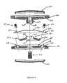
- FIG. 6is an exploded view of an embodiment of the present invention, utilizing the lower and upper plate members of FIGS. 3 a , 3 b , 4 a and 4 b and the belleville washer of FIGS. 5 a and 5 b.
- FIG. 7is an assembled view of the embodiment of the present invention shown in FIG. 6 .
- FIGS. 3 a , 3 b , 4 a and 4 bside cross-section and top views of lower and upper plate members 100 , 200 of an artificial intervertebral disc of the present invention are shown, each of the plate members 100 , 200 having a vertebral body contact surface 102 , 202 . Because the disc is to be positioned between the facing surfaces of adjacent vertebral bodies, the plate members 100 , 200 are disposed such that the vertebral body contact surfaces 102 , 202 face away from one another as shown.
- the plate members 100 , 200are to mate with the vertebral bodies so as to not rotate relative thereto, but rather to permit the spinal segments to axially compress and bend relative to one another in manners that mimic the natural motion of the spinal segment. This motion is permitted by the performance of a spring member (described in greater detail below) disposed between the secured plates 100 , 200 .
- a spring memberdescribed in greater detail below
- each plate member 100 , 200is a flat metal plate having an overall shape that conforms to the overall shape of the respective bone endplate of the vertebral body with which it is to mate.
- Each plate member 100 , 200includes a peripheral region 100 A, 200 A extending about the outer region of the respective flat metal plate.
- each plate member 100 , 200comprises an oval convex metal mesh 102 , 202 that is attached to the exterior surface 101 , 201 of the plate member 100 , 200 .
- the convex metal mesh 102 , 202is secured at its perimeter, by laser welds, to the exterior surface 101 , 201 of the respective plate member 100 , 200 .
- the metal mesh 102 , 202is domed in its initial undeflected conformation, but deflects as necessary during insertion of the artificial intervertebral disc between vertebral bodies, and, once the artificial intervertebral disc is seated between the vertebral bodies, deforms as necessary under anatomical loads to reshape itself to the concave surface of the vertebral endplate. This affords the plate member 100 , 200 having the metal mesh 102 , 202 substantially superior gripping and holding strength upon initial implantation as compared with other artificial disc products.
- the convex metal mesh 102 , 202further provides an osteoconductive surface through which the bone may ultimately grow.
- the meshis preferably comprised of titanium, but can also be formed from other metals and/or non-metals without departing from the scope of the present invention.
- each plate member 100 , 200further comprises at least a lateral ring 105 , 205 of porous coating (which may be a sprayed deposition layer, or an adhesive applied beaded metal layer, or other suitable porous coatings known in the art).
- This porous ring 105 , 205permits the long-term ingrowth of vertebral bone into the plate member 100 , 200 , thus permanently securing the prosthesis within the intervertebral space.
- this porous layer 105 , 205may extend beneath the domed metal mesh 102 , 202 as well, but is more importantly applied to the lateral rim of the exterior surface 101 , 201 of the plate member 100 , 200 that seats directly against the vertebral body.
- wire mesh attachment devices and methods described hereincan be used not only with the artificial intervertebral discs and artificial intervertebral disc endplates described or referred to herein, but also with other artificial intervertebral discs and artificial intervertebral disc endplates, including those currently known in the art. Therefore, the description of the wire mesh attachment devices and methods being used with the artificial intervertebral discs and artificial intervertebral disc endplates described or referred to herein should not be construed as limiting the application and/or usefulness of the wire mesh attachment device.
- the plate members 100 , 200each comprise features for coupling the spring member (described below) therebetween (as described below). More specifically, the lower plate member 100 includes an internal Lace 103 that includes a circular recess 109 and a pair of holes 108 though which rivets 104 (shown in FIGS. 6 and 7 ) may be provided for securing a shield 250 (more fully set forth hereinbelow with and shown on FIG. 6 ).
- the upper plate member 200includes an internal face 203 that includes a central interiorly directed ball-shaped protuberance 207 .
- the protuberance 207includes a series of slots 208 (shown on FIG.
- the protuberance 207further includes a central threaded axial bore 209 that is designed to receive a rivet 210 (shown in FIGS. 6 and 7 ). Prior to the insertion of the rivet 210 , the protuberance 207 can deflect radially inward because the slots 208 will narrow under radial pressure. The insertion of the rivet 210 eliminates the capacity for this deflection.
- the protuberance 207before receiving the rivet 210 , can be compressed to seat in the socket portion of the spring member (as described below), and, once the protuberance 207 has been seated in the socket portion, the rivet 210 can be inserted into the axial bore 209 to ensure that the protuberance 207 remains bald in the socket portion.
- a holecan be provided in the lower plate member 100 so that the interior of the device may be readily accessed if a need should arise.
- a spring member 130 for disposition between the plate members 100 , 200is shown in side cross-section and perspective views as a spirally slotted belleville washer 130 having radially extending grooves.
- the belleville washer 130is a restoring force providing device which comprises a circular shape, having a central opening 132 , and which is radially arched in shape.
- the belleville washer 130has a radial convexity (i.e., the height of the washer 130 is not linearly related to the radial distance, but may, for example, be parabolic in shape).
- the restoring force of the belleville washer 130is proportional to the elastic properties of the material.
- belleville washerscan be used with the present invention, and that belleville washers having other conformations, that is, without or without slots and/or grooves, and/or with other groove and slots configurations, including the same or different numbers of grooves and/or slots, are encompassed by the present invention.
- the belleville washer 130comprises a series of spiral slots 131 formed therein.
- the slots 131extend from the outer edge of the belleville washer 130 , inward along arcs generally directed toward the center of the element.
- the slots 131do not extend fully to the center of the element.
- the slots 131extend anywhere from a quarter to three quarters of the overall radius of the washer 130 , depending upon the requirements of the patient, and the anatomical requirements of the device.
- the belleville washer 130further comprises a series of grooves 133 formed therein.
- the grooves 133extend radially from the outer edge of the belleville washer 130 toward the center of the element.
- the width 135 and depth 137 of each groove 133decreases along the length of the groove 133 from the outer edge of the washer 130 toward the center of the washer 130 , such that the center of the washer 130 is flat, while the outer edge of the washer 130 has grooves of a maximum groove depth.
- each groovecan be (1) increasing along the length of the groove from the outer edge of the washer toward the center of the washer, (2) uniform along the length of the groove from the outer edge of the washer toward the center of the washer, or (3) varied along the length of each groove from the outer edge of the washer toward the center of the washer, either randomly or according to a pattern.
- each grooveis not formed similarly to one or more other grooves, but rather one or more grooves are formed in any of the above-mentioned fashions, while one or more other grooves are formed in another of the above-mentioned fashions or other fashions. It should be clear that any groove pattern can be implemented without departing from the scope of the present invention.
- the belleville washer 130responds to a compressive load by deflecting compressively; the spiral slots and/or radial grooves cause the washer to further respond to the load by spreading as the slots and/or the grooves in the washer expand under the load.
- the springtherefore, provides a restoring force which is proportional to the elastic modulus of the material in a hoop stressed condition.
- the socket portionis provided inasmuch as the central opening 132 of the belleville washer 130 is enlarged.
- This central opening 132includes a curvate volume 233 for receiving therein the ball-shaped protuberance 207 of the upper plate 200 .
- the curvate volume 233has a substantially constant radius of curvature which is also substantially equivalent to the radius of the ball-shaped protuberance 207 .
- the spiral slots 131 of the washer 130do not extend all the way to the central opening 132 , and approach the opening 132 only as far as the material strength of the washer 130 can handle without plastically deforming under the expected anatomical loading.
- each groove 133 of the washer 130decreases along the length of the groove 133 from the outer edge of the washer 130 toward the center of the washer 130 , such that the center of the washer 130 is flat, while the outer edge of the washer 130 has grooves of a maximum groove depth. Therefore, the central opening 132 can be formed from flat edges. It should be understood that this is not required, but rather is preferred for this embodiment.
- the devicecomprises a first plate member 200 , having an upper, exterior, surface 201 and a lower interior surface 203 angled with respect to exterior surface 201 , said upper, exterior surface 201 including a portion 205 thereof which is a porous, and a convex wire mesh 202 .
- Peripheral region or first side surface 200 Ais formed between the exterior surface 201 and the interior surface 203 .
- the lower, interior surface 203includes a ball-shaped protuberance 207 extending out therefrom, said ball-shaped protuberance 207 including slits 208 and an axial bore 209 therein for permitting it to deflect inward under a compressive load.
- a rivet 210is provided for selective insertion into said axial bore 209 of said ball-shaped protuberance 207 for inhibiting said inward deflection of the slits 208 once it has been inserted into the socket 233 .
- a second plate member 100disposed in parallel with said first plate 200 also has an upper, interior, surface 103 including a circular recess 109 formed therein, and a lower, exterior surface 101 , wherein the interior, surface 103 is angled with respect to exterior surface 101 , the exterior surface 101 having a portion 105 which includes a porous coating and a convex mesh 102 .
- Peripheral region or second side surface 100 Ais formed between the exterior surface 101 and the interior surface 103 .
- the belleville washer 130 described aboveis shown with the ball-shaped socket 233 of its central opening 132 portion including a ball-shaped socket 233 for receiving and retaining therein the ball-shaped protuberance 207 of the first plate 200 .
- the shield 250can be secured over the washer 130 by passing the central hole 251 of the shield 250 over the central opening 132 and applying the rivets 104 through rivet holes 252 in the shield 250 and through the rivet holes 108 in the lower plate 100 .
- the protuberance 207can be compressed into and thereby received in the socket 233 and the rivet 210 can then be received in the axial bore 209 to prevent the protuberance 207 from thereafter exiting the socket 233 .
- the belleville washer 130can rotate and angulate on the protuberance to permit normal anatomical rotation and angulation. Further, because the diameter of the circular recess 109 is greater than the diameter of the wide end of the belleville washer 130 , compressive loading of the device (and therefore the washer) can result in an unrestrained radial deflection of the washer 130 , as necessary for proper anatomical response. The spiral slots 131 and radial grooves 133 of the washer 130 enhance this deflection. When the load is removed, the washer 130 springs back to its original shape.
- the artificial intervertebral disccan withstand tension loading of the plate members 100 , 200 , as necessary for proper anatomical response. More particularly, when a tension load is applied to the plate members 100 , 200 , the ball-shaped protuberance 207 in the ball-shaped socket 233 of the belleville washer 130 seeks to radially compress to fit through the central opening 132 of the ball-shaped socket 233 . However, the rivet 210 in the axial bore 209 of the protuberance 207 prevents the radial compression, thereby preventing the protuberance 207 from exiting the socket 233 .
- the rivets 104 holding the shield 250 in place over the belleville washer 130prevent the shield 250 from separating from the lower plate member 100 when the belleville washer 130 presses against the inner surface of the shield 250 . Therefore, the assembly does not come apart under normally experienced tension loads. This ensures that no individual parts of the assembly will pop out or slip out from between the vertebral bodies when the patient stretches or hangs while exercising or performing other activities.
- the disc assemblyin combination with the securing of the plate members 100 , 200 to the adjacent vertebral bones via the wire mesh domes 102 , 202 , the disc assembly has an integrity similar to the tension-bearing integrity of a healthy natural intervertebral disc.
- the disc assemblyprovides a centroid of motion within the protuberance 207 . Accordingly, the centroid of motion of the disc assembly remains centrally located between the vertebral bodies, similar to the centroid of motion in a healthy natural intervertebral disc.
Landscapes
- Health & Medical Sciences (AREA)
- Engineering & Computer Science (AREA)
- Biomedical Technology (AREA)
- Neurology (AREA)
- Orthopedic Medicine & Surgery (AREA)
- Cardiology (AREA)
- Oral & Maxillofacial Surgery (AREA)
- Transplantation (AREA)
- Heart & Thoracic Surgery (AREA)
- Vascular Medicine (AREA)
- Life Sciences & Earth Sciences (AREA)
- Animal Behavior & Ethology (AREA)
- General Health & Medical Sciences (AREA)
- Public Health (AREA)
- Veterinary Medicine (AREA)
- Prostheses (AREA)
Abstract
Description
Claims (9)
Priority Applications (47)
| Application Number | Priority Date | Filing Date | Title |
|---|---|---|---|
| US10/151,280US7604664B2 (en) | 2001-07-16 | 2002-05-20 | Spinal baseplates with ball joint coupling and a retaining member |
| US10/175,417US7563285B2 (en) | 2001-07-16 | 2002-06-19 | Artificial intervertebral disc utilizing a ball joint coupling |
| US10/256,160US6989032B2 (en) | 2001-07-16 | 2002-09-26 | Artificial intervertebral disc |
| US10/282,356US7169182B2 (en) | 2001-07-16 | 2002-10-29 | Implanting an artificial intervertebral disc |
| US10/294,981US7101399B2 (en) | 2001-07-16 | 2002-11-14 | Artificial intervertebral disc having a captured ball and socket joint with a solid ball and compression locking post |
| US10/294,982US7022139B2 (en) | 2001-07-16 | 2002-11-14 | Artificial intervertebral disc having limited rotation using a captured ball and socket joint with a solid ball and retaining cap |
| US10/294,980US7118599B2 (en) | 2001-07-16 | 2002-11-14 | Artificial intervertebral disc |
| US10/294,989US7044970B2 (en) | 2001-07-16 | 2002-11-14 | Artificial intervertebral disc having limited rotation using a captured ball and socket joint with a solid ball, a compression locking post, and an interference ball bearing |
| US10/294,984US7044969B2 (en) | 2001-07-16 | 2002-11-14 | Artificial intervertebral disc having limited rotation using a captured ball and socket joint with a retaining cap and a solid ball having a protrusion |
| US10/294,985US7060098B2 (en) | 2001-07-16 | 2002-11-14 | Artificial intervertebral disc having limited rotation using a captured ball and socket joint with a compression locking post and a solid ball having a protrusion |
| US10/294,988US7163559B2 (en) | 2001-07-16 | 2002-11-14 | Artificial intervertebral disc having limited rotation using a captured ball and socket joint with a solid ball, a retaining cap, and an interference ball bearing |
| US10/294,983US7258699B2 (en) | 2001-07-16 | 2002-11-14 | Artificial intervertebral disc having a captured ball and socket joint with a solid ball and retaining cap |
| US10/294,986US7066959B2 (en) | 2001-07-16 | 2002-11-14 | Artificial intervertebral disc having limited rotation using a captured ball and socket joint with a solid ball, a compression locking post, and an interference pin |
| US10/309,585US7115132B2 (en) | 2001-07-16 | 2002-12-04 | Static trials and related instruments and methods for use in implanting an artificial intervertebral disc |
| US10/425,267US7235081B2 (en) | 2001-07-16 | 2003-04-29 | Wedge plate inserter/impactor and related methods for use in implanting an artificial intervertebral disc |
| US10/642,524US7186268B2 (en) | 2001-07-16 | 2003-08-15 | Axially compressible artificial interverterbral disc having a captured ball and socket joint with a solid ball and retaining cap |
| US10/642,527US7223290B2 (en) | 2001-07-16 | 2003-08-15 | Axially compressible artificial intervertebral disc having a captured ball and socket joint with a solid ball and compression locking post |
| US10/642,529US20040034422A1 (en) | 2001-07-16 | 2003-08-15 | Intervertebral spacer device having a circumferentially buried wire mesh endplate attachment device |
| US10/642,528US7160327B2 (en) | 2001-07-16 | 2003-08-15 | Axially compressible artificial intervertebral disc having limited rotation using a captured ball and socket joint with a solid ball and compression locking post |
| US10/642,523US7141069B2 (en) | 2001-07-16 | 2003-08-15 | Axially compressible artificial intervertebral disc having limited rotation using a captured ball and socket joint with a solid ball and retaining cap |
| US10/642,522US20040034420A1 (en) | 2001-07-16 | 2003-08-15 | Artificial intervertebral disc having a circumferentially buried wire mesh endplate attachment device |
| US10/642,526US20040034421A1 (en) | 2001-07-16 | 2003-08-15 | Circumferentially buried wire mesh endplate attachment device for use with an orthopedic device |
| US10/663,488US7811287B2 (en) | 2001-07-16 | 2003-09-16 | Intervertebral spacer device having an engagement hole for a tool with an extendable post |
| US10/663,486US7491241B2 (en) | 2001-07-16 | 2003-09-16 | Intervertebral spacer device having recessed notch pairs for manipulation using a surgical tool |
| US10/663,492US7223291B2 (en) | 2001-07-16 | 2003-09-16 | Intervertebral spacer device having engagement hole pairs for manipulation using a surgical tool |
| US10/663,493US8366775B2 (en) | 2001-07-16 | 2003-09-16 | Intervertebral spacer device having an angled perimeter for manipulation using a surgical tool |
| US10/663,487US7635368B2 (en) | 2001-07-16 | 2003-09-16 | Intervertebral spacer device having simultaneously engageable angled perimeters for manipulation using a surgical tool |
| US10/782,981US7575576B2 (en) | 2001-07-16 | 2004-02-20 | Wedge ramp distractor and related methods for use in implanting artificial intervertebral discs |
| US10/783,152US20050143747A1 (en) | 2001-07-16 | 2004-02-20 | Parallel distractor and related methods for use in implanting an artificial intervertebral disc |
| US10/784,637US8636804B2 (en) | 2001-07-16 | 2004-02-23 | Instrumentation for properly seating an artificial intervertebral disc in an intervertebral space |
| US10/784,646US7811289B2 (en) | 2001-07-16 | 2004-02-23 | Artificial intervertebral disc trial having a controllably separable distal end |
| US10/784,645US8858564B2 (en) | 2001-02-15 | 2004-02-23 | Wedge plate inserter/impactor and related methods for use in implanting an artificial intervertebral disc |
| US10/784,628US7842043B2 (en) | 2001-07-16 | 2004-02-23 | Instrumentation for inserting and impacting an artificial intervertebral disc in an intervertebral space |
| US10/784,629US7632281B2 (en) | 2001-07-16 | 2004-02-23 | Instrumentation for manipulating artificial intervertebral disc trials having a cylindrical engagement surface |
| US10/784,597US8357167B2 (en) | 2001-07-16 | 2004-10-12 | Artificial intervertebral disc trials with baseplates having inward tool engagement holes |
| US10/784,598US8758358B2 (en) | 2001-07-16 | 2004-10-12 | Instrumentation for repositioning and extraction an artificial intervertebral disc from an intervertebral space |
| US11/657,268US20070123906A1 (en) | 2001-07-16 | 2007-01-24 | Inserter/impactor for implanting an artificial intervertebral disc |
| US11/716,360US8303659B2 (en) | 2001-07-16 | 2007-03-09 | Intervertebral spacer device having engagement hole pairs |
| US11/789,327US20070198092A1 (en) | 2001-07-16 | 2007-04-24 | System for inserting artificial intervertebral discs |
| US12/321,562US8940047B2 (en) | 2001-02-15 | 2009-01-22 | Intervertebral spacer device having recessed notch pairs for manipulation using a surgical tool |
| US12/501,889US9132020B2 (en) | 2001-07-16 | 2009-07-13 | Wedge ramp distractor for use in implanting artificial intervertebral discs |
| US12/938,080US8545564B2 (en) | 2001-07-16 | 2010-11-02 | Intervertebral spacer device having an articulation member and housing |
| US13/911,663US20130345812A1 (en) | 2001-07-16 | 2013-06-06 | Intervertebral spacer device having a circumferentially buried wire mesh endplate attachment device |
| US14/340,091US9814596B2 (en) | 2001-07-16 | 2014-07-24 | Method of orienting an intervertebral spacer device having recessed notch pairs by using a surgical tool |
| US15/014,803US9700429B2 (en) | 2001-07-16 | 2016-02-03 | Intervertebral spacer device having recessed notch pairs for manipulation using a surgical tool |
| US15/618,566US20170273805A1 (en) | 2001-07-16 | 2017-06-09 | Intervertebral spacer device having recessed notch pairs for manipulation using a surgical tool |
| US15/726,958US20180028330A1 (en) | 2001-07-16 | 2017-10-06 | Intervertebral spacer device having recessed notch pairs for manipulation using a surgical tool |
Applications Claiming Priority (7)
| Application Number | Priority Date | Filing Date | Title |
|---|---|---|---|
| US09/906,119US6607559B2 (en) | 2001-07-16 | 2001-07-16 | Trial intervertebral distraction spacers |
| US09/968,046US20020111687A1 (en) | 2001-02-15 | 2001-10-01 | Intervertebral spacer device utilizing a belleville washer having radially extending grooves |
| US09/970,479US6669730B2 (en) | 2001-02-15 | 2001-10-04 | Intervertebral spacer device utilizing a spirally slotted belleville washer having radially extending grooves |
| US09/982,148US6673113B2 (en) | 2001-10-18 | 2001-10-18 | Intervertebral spacer device having arch shaped spring elements |
| US10/128,619US6863689B2 (en) | 2001-07-16 | 2002-04-23 | Intervertebral spacer having a flexible wire mesh vertebral body contact element |
| US10/140,153US20030069642A1 (en) | 2001-10-04 | 2002-05-07 | Artificial intervertebral disc having a flexible wire mesh vertebral body contact element |
| US10/151,280US7604664B2 (en) | 2001-07-16 | 2002-05-20 | Spinal baseplates with ball joint coupling and a retaining member |
Related Parent Applications (6)
| Application Number | Title | Priority Date | Filing Date |
|---|---|---|---|
| US09/968,046ContinuationUS20020111687A1 (en) | 2001-02-15 | 2001-10-01 | Intervertebral spacer device utilizing a belleville washer having radially extending grooves |
| US09/970,479Continuation-In-PartUS6669730B2 (en) | 2001-02-15 | 2001-10-04 | Intervertebral spacer device utilizing a spirally slotted belleville washer having radially extending grooves |
| US09/970,479ContinuationUS6669730B2 (en) | 2001-02-15 | 2001-10-04 | Intervertebral spacer device utilizing a spirally slotted belleville washer having radially extending grooves |
| US10/128,619ContinuationUS6863689B2 (en) | 2001-02-15 | 2002-04-23 | Intervertebral spacer having a flexible wire mesh vertebral body contact element |
| US10/140,153Continuation-In-PartUS20030069642A1 (en) | 2001-02-15 | 2002-05-07 | Artificial intervertebral disc having a flexible wire mesh vertebral body contact element |
| US10/140,153ContinuationUS20030069642A1 (en) | 2001-02-15 | 2002-05-07 | Artificial intervertebral disc having a flexible wire mesh vertebral body contact element |
Related Child Applications (2)
| Application Number | Title | Priority Date | Filing Date |
|---|---|---|---|
| US10/175,417Continuation-In-PartUS7563285B2 (en) | 2001-02-15 | 2002-06-19 | Artificial intervertebral disc utilizing a ball joint coupling |
| US10/175,417ContinuationUS7563285B2 (en) | 2001-02-15 | 2002-06-19 | Artificial intervertebral disc utilizing a ball joint coupling |
Publications (2)
| Publication Number | Publication Date |
|---|---|
| US20030069643A1 US20030069643A1 (en) | 2003-04-10 |
| US7604664B2true US7604664B2 (en) | 2009-10-20 |
Family
ID=26837911
Family Applications (1)
| Application Number | Title | Priority Date | Filing Date |
|---|---|---|---|
| US10/151,280Expired - Fee RelatedUS7604664B2 (en) | 2001-02-15 | 2002-05-20 | Spinal baseplates with ball joint coupling and a retaining member |
Country Status (1)
| Country | Link |
|---|---|
| US (1) | US7604664B2 (en) |
Cited By (5)
| Publication number | Priority date | Publication date | Assignee | Title |
|---|---|---|---|---|
| US8425609B2 (en)* | 2004-02-20 | 2013-04-23 | Spinecore, Inc. | Artificial intervertebral disc having a bored semispherical bearing with a compression locking post and retaining caps |
| US8777959B2 (en) | 2005-05-27 | 2014-07-15 | Spinecore, Inc. | Intervertebral disc and insertion methods therefor |
| US9358122B2 (en) | 2011-01-07 | 2016-06-07 | K2M, Inc. | Interbody spacer |
| US9539114B2 (en) | 2005-05-27 | 2017-01-10 | Spinecore, Inc. | Instruments and methods for inserting artificial intervertebral implants |
| US11096802B2 (en) | 2018-03-03 | 2021-08-24 | K2M, Inc. | Intervertebral trial with marker |
Families Citing this family (57)
| Publication number | Priority date | Publication date | Assignee | Title |
|---|---|---|---|---|
| US7011684B2 (en)* | 2002-01-17 | 2006-03-14 | Concept Matrix, Llc | Intervertebral disk prosthesis |
| US7717959B2 (en)* | 2002-03-30 | 2010-05-18 | Lytton William | Intervertebral device and method of use |
| WO2003099148A2 (en)* | 2002-05-21 | 2003-12-04 | Sdgi Holdings, Inc. | Vertebrae bone anchor and cable for coupling it to a rod |
| US8388684B2 (en) | 2002-05-23 | 2013-03-05 | Pioneer Signal Technology, Inc. | Artificial disc device |
| BRPI0409091A (en)* | 2003-04-07 | 2006-04-11 | Cervitech Inc | intervertebral joint prosthesis for the cervical spine |
| US8012212B2 (en) | 2003-04-07 | 2011-09-06 | Nuvasive, Inc. | Cervical intervertebral disk prosthesis |
| US7291173B2 (en) | 2003-05-06 | 2007-11-06 | Aesculap Ii, Inc. | Artificial intervertebral disc |
| US7105024B2 (en)* | 2003-05-06 | 2006-09-12 | Aesculap Ii, Inc. | Artificial intervertebral disc |
| US20050143824A1 (en)* | 2003-05-06 | 2005-06-30 | Marc Richelsoph | Artificial intervertebral disc |
| DE10324108B3 (en)* | 2003-05-21 | 2005-01-27 | Aesculap Ag & Co. Kg | Backbone implant is inserted with contracted contact disc which is expanded to optimum area following insertion |
| DE20310433U1 (en) | 2003-07-08 | 2003-09-04 | Aesculap AG & Co. KG, 78532 Tuttlingen | Surgical device for inserting dual component implant into appropriate space at spine, comprising particularly shaped holding area |
| DE10330698B4 (en)* | 2003-07-08 | 2005-05-25 | Aesculap Ag & Co. Kg | Intervertebral implant |
| US7909869B2 (en)* | 2003-08-05 | 2011-03-22 | Flexuspine, Inc. | Artificial spinal unit assemblies |
| US7316714B2 (en)* | 2003-08-05 | 2008-01-08 | Flexuspine, Inc. | Artificial functional spinal unit assemblies |
| US7204853B2 (en)* | 2003-08-05 | 2007-04-17 | Flexuspine, Inc. | Artificial functional spinal unit assemblies |
| US7753958B2 (en)* | 2003-08-05 | 2010-07-13 | Gordon Charles R | Expandable intervertebral implant |
| US7799082B2 (en) | 2003-08-05 | 2010-09-21 | Flexuspine, Inc. | Artificial functional spinal unit system and method for use |
| DE10339170B4 (en)* | 2003-08-22 | 2009-10-15 | Aesculap Ag | Intervertebral implant |
| US7655012B2 (en)* | 2003-10-02 | 2010-02-02 | Zimmer Spine, Inc. | Methods and apparatuses for minimally invasive replacement of intervertebral discs |
| DE20315613U1 (en)* | 2003-10-08 | 2003-12-11 | Aesculap Ag & Co. Kg | Intervertebral implant |
| US8123757B2 (en)* | 2003-12-31 | 2012-02-28 | Depuy Spine, Inc. | Inserter instrument and implant clip |
| US7625379B2 (en)* | 2004-01-26 | 2009-12-01 | Warsaw Orthopedic, Inc. | Methods and instrumentation for inserting intervertebral grafts and devices |
| DE202004009542U1 (en)* | 2004-06-16 | 2004-08-12 | Aesculap Ag & Co. Kg | Artificial intervertebral disk, comprising core with intensely curved upper and less curved lower surface |
| US20060009541A1 (en)* | 2004-07-09 | 2006-01-12 | Yih-Fang Chen | Saturant for friction material containing friction modifying layer |
| US8911498B2 (en)* | 2005-02-10 | 2014-12-16 | DePuy Synthes Products, LLC | Intervertebral prosthetic disc |
| US7690381B2 (en)* | 2005-02-10 | 2010-04-06 | Depuy Spine, Inc. | Intervertebral prosthetic disc and method for installing using a guidewire |
| WO2006104722A2 (en)* | 2005-03-24 | 2006-10-05 | Accelerated Innovation, Llc | Intervertebral disc replacement device |
| US7867279B2 (en)* | 2006-01-23 | 2011-01-11 | Depuy Spine, Inc. | Intervertebral disc prosthesis |
| US8118869B2 (en) | 2006-03-08 | 2012-02-21 | Flexuspine, Inc. | Dynamic interbody device |
| US8016886B2 (en) | 2006-07-18 | 2011-09-13 | Altus Partners, Llc | Intervertebral disc replacement device |
| US7976550B2 (en)* | 2006-08-10 | 2011-07-12 | Pioneer Surgical Technology | Insertion instrument for artificial discs |
| US8409213B2 (en)* | 2006-08-10 | 2013-04-02 | Pioneer Surgical Technology, Inc. | Insertion instrument for artificial discs |
| US8118872B2 (en) | 2006-08-10 | 2012-02-21 | Pioneer Surgical Technology, Inc. | System and methods for inserting a spinal disc device into an intervertebral space |
| US8414616B2 (en)* | 2006-09-12 | 2013-04-09 | Pioneer Surgical Technology, Inc. | Mounting devices for fixation devices and insertion instruments used therewith |
| EP2073761B1 (en) | 2006-09-21 | 2010-07-07 | SpineCore, Inc. | Intervertebral disc implants and tooling |
| US8372084B2 (en) | 2006-09-22 | 2013-02-12 | Pioneer Surgical Technology, Inc. | System and methods for inserting a spinal disc device into an intervertebral space |
| US7959677B2 (en) | 2007-01-19 | 2011-06-14 | Flexuspine, Inc. | Artificial functional spinal unit system and method for use |
| US8579910B2 (en) | 2007-05-18 | 2013-11-12 | DePuy Synthes Products, LLC | Insertion blade assembly and method of use |
| US8162994B2 (en) | 2007-10-22 | 2012-04-24 | Flexuspine, Inc. | Posterior stabilization system with isolated, dual dampener systems |
| US8523912B2 (en) | 2007-10-22 | 2013-09-03 | Flexuspine, Inc. | Posterior stabilization systems with shared, dual dampener systems |
| US8157844B2 (en) | 2007-10-22 | 2012-04-17 | Flexuspine, Inc. | Dampener system for a posterior stabilization system with a variable length elongated member |
| US8182514B2 (en) | 2007-10-22 | 2012-05-22 | Flexuspine, Inc. | Dampener system for a posterior stabilization system with a fixed length elongated member |
| US8187330B2 (en) | 2007-10-22 | 2012-05-29 | Flexuspine, Inc. | Dampener system for a posterior stabilization system with a variable length elongated member |
| US8267965B2 (en) | 2007-10-22 | 2012-09-18 | Flexuspine, Inc. | Spinal stabilization systems with dynamic interbody devices |
| US20090248161A1 (en)* | 2008-03-20 | 2009-10-01 | K2M, Inc. | Artificial disc replacement device |
| US8906033B2 (en)* | 2009-03-30 | 2014-12-09 | DePuy Synthes Products, LLC | Cervical motion disc inserter |
| US8388687B2 (en) | 2011-03-25 | 2013-03-05 | Flexuspine, Inc. | Interbody device insertion systems and methods |
| US9526627B2 (en) | 2011-11-17 | 2016-12-27 | Exactech, Inc. | Expandable interbody device system and method |
| US9308101B2 (en)* | 2012-10-24 | 2016-04-12 | TrueMotion Spine, Inc. | Shock absorbing, total disc replacement prosthetic device |
| US9492288B2 (en) | 2013-02-20 | 2016-11-15 | Flexuspine, Inc. | Expandable fusion device for positioning between adjacent vertebral bodies |
| WO2014145766A1 (en)* | 2013-03-15 | 2014-09-18 | Paradigm Spine, Llc | Modular, customizable spine stabilization system |
| CN103239306A (en)* | 2013-04-23 | 2013-08-14 | 柏传毅 | Manufacturing method of angled artificial intervertebral disc |
| US9198770B2 (en)* | 2013-07-31 | 2015-12-01 | Globus Medical, Inc. | Artificial disc devices and related methods of use |
| US10398565B2 (en) | 2014-04-24 | 2019-09-03 | Choice Spine, Llc | Limited profile intervertebral implant with incorporated fastening and locking mechanism |
| US9517144B2 (en) | 2014-04-24 | 2016-12-13 | Exactech, Inc. | Limited profile intervertebral implant with incorporated fastening mechanism |
| WO2019051260A1 (en) | 2017-09-08 | 2019-03-14 | Pioneer Surgical Technology, Inc. | Intervertebral implants, instruments, and methods |
| USD907771S1 (en) | 2017-10-09 | 2021-01-12 | Pioneer Surgical Technology, Inc. | Intervertebral implant |
Citations (74)
| Publication number | Priority date | Publication date | Assignee | Title |
|---|---|---|---|---|
| US2193122A (en)* | 1937-09-23 | 1940-03-12 | Westinghouse Electric & Mfg Co | Electric switch |
| US3867728A (en) | 1971-12-30 | 1975-02-25 | Cutter Lab | Prosthesis for spinal repair |
| US4309777A (en) | 1980-11-13 | 1982-01-12 | Patil Arun A | Artificial intervertebral disc |
| US4605417A (en) | 1984-10-03 | 1986-08-12 | Fleischauer K E | Prosthetic joint |
| US4759769A (en) | 1987-02-12 | 1988-07-26 | Health & Research Services Inc. | Artificial spinal disc |
| US4759766A (en) | 1984-09-04 | 1988-07-26 | Humboldt-Universitaet Zu Berlin | Intervertebral disc endoprosthesis |
| US4932969A (en) | 1987-01-08 | 1990-06-12 | Sulzer Brothers Limited | Joint endoprosthesis |
| US4997432A (en) | 1988-03-23 | 1991-03-05 | Waldemar Link Gmbh & Co. | Surgical instrument set |
| US5112178A (en)* | 1990-08-08 | 1992-05-12 | Teckentrup Gmbh & Co. Kg | Spring washer for securing screws, nuts or the like |
| US5236460A (en) | 1990-02-12 | 1993-08-17 | Midas Rex Pneumatic Tools, Inc. | Vertebral body prosthesis |
| US5258007A (en) | 1992-05-14 | 1993-11-02 | Robert F. Spetzler | Powered surgical instrument |
| US5314477A (en) | 1990-03-07 | 1994-05-24 | J.B.S. Limited Company | Prosthesis for intervertebral discs and instruments for implanting it |
| US5370697A (en) | 1992-04-21 | 1994-12-06 | Sulzer Medizinaltechnik Ag | Artificial intervertebral disk member |
| US5401269A (en) | 1992-03-13 | 1995-03-28 | Waldemar Link Gmbh & Co. | Intervertebral disc endoprosthesis |
| US5425773A (en) | 1992-01-06 | 1995-06-20 | Danek Medical, Inc. | Intervertebral disk arthroplasty device |
| US5458642A (en) | 1994-01-18 | 1995-10-17 | Beer; John C. | Synthetic intervertebral disc |
| US5507816A (en) | 1991-12-04 | 1996-04-16 | Customflex Limited | Spinal vertebrae implants |
| US5556431A (en) | 1992-03-13 | 1996-09-17 | B+E,Uml U+Ee Ttner-Janz; Karin | Intervertebral disc endoprosthesis |
| US5674296A (en) | 1994-11-14 | 1997-10-07 | Spinal Dynamics Corporation | Human spinal disc prosthesis |
| US5676701A (en) | 1993-01-14 | 1997-10-14 | Smith & Nephew, Inc. | Low wear artificial spinal disc |
| US5676702A (en) | 1994-12-16 | 1997-10-14 | Tornier S.A. | Elastic disc prosthesis |
| US5683465A (en) | 1996-03-18 | 1997-11-04 | Shinn; Gary Lee | Artificial intervertebral disk prosthesis |
| US5755796A (en) | 1996-06-06 | 1998-05-26 | Ibo; Ivo | Prosthesis of the cervical intervertebralis disk |
| US5782832A (en) | 1996-10-01 | 1998-07-21 | Surgical Dynamics, Inc. | Spinal fusion implant and method of insertion thereof |
| US5827328A (en) | 1996-11-22 | 1998-10-27 | Buttermann; Glenn R. | Intervertebral prosthetic device |
| US5888226A (en) | 1997-11-12 | 1999-03-30 | Rogozinski; Chaim | Intervertebral prosthetic disc |
| US5893889A (en)* | 1997-06-20 | 1999-04-13 | Harrington; Michael | Artificial disc |
| US5895428A (en) | 1996-11-01 | 1999-04-20 | Berry; Don | Load bearing spinal joint implant |
| US5899941A (en) | 1997-12-09 | 1999-05-04 | Chubu Bearing Kabushiki Kaisha | Artificial intervertebral disk |
| US5989291A (en) | 1998-02-26 | 1999-11-23 | Third Millennium Engineering, Llc | Intervertebral spacer device |
| US6019792A (en) | 1998-04-23 | 2000-02-01 | Cauthen Research Group, Inc. | Articulating spinal implant |
| US6039763A (en) | 1998-10-27 | 2000-03-21 | Disc Replacement Technologies, Inc. | Articulating spinal disc prosthesis |
| US6063121A (en) | 1998-07-29 | 2000-05-16 | Xavier; Ravi | Vertebral body prosthesis |
| US6113637A (en) | 1998-10-22 | 2000-09-05 | Sofamor Danek Holdings, Inc. | Artificial intervertebral joint permitting translational and rotational motion |
| US6136031A (en) | 1998-06-17 | 2000-10-24 | Surgical Dynamics, Inc. | Artificial intervertebral disc |
| US6146421A (en) | 1997-08-04 | 2000-11-14 | Gordon, Maya, Roberts And Thomas, Number 1, Llc | Multiple axis intervertebral prosthesis |
| US6179874B1 (en) | 1998-04-23 | 2001-01-30 | Cauthen Research Group, Inc. | Articulating spinal implant |
| US6228118B1 (en) | 1997-08-04 | 2001-05-08 | Gordon, Maya, Roberts And Thomas, Number 1, Llc | Multiple axis intervertebral prosthesis |
| US20010016773A1 (en) | 1998-10-15 | 2001-08-23 | Hassan Serhan | Spinal disc |
| US6368350B1 (en) | 1999-03-11 | 2002-04-09 | Sulzer Spine-Tech Inc. | Intervertebral disc prosthesis and method |
| US6375682B1 (en) | 2001-08-06 | 2002-04-23 | Lewis W. Fleischmann | Collapsible, rotatable and expandable spinal hydraulic prosthetic device |
| US20020084562A1 (en)* | 2000-12-29 | 2002-07-04 | Kelsey Donald J. | Disk spring |
| US20020111682A1 (en) | 2001-02-15 | 2002-08-15 | Ralph James D. | Intervertebral spacer device having a radially thinning belleville spring |
| US20020111681A1 (en) | 2001-02-15 | 2002-08-15 | Ralph James D. | Intervertebral spacer device having a radially thinning slotted belleville spring |
| US20020111684A1 (en) | 2001-02-15 | 2002-08-15 | Ralph James D. | Intervertebral spacer device utilizing a belleville washer having radially spaced concentric grooves |
| US20020111685A1 (en) | 2001-02-15 | 2002-08-15 | Ralph James D. | Intervertebral spacer device utilizing a spirally slotted belleville washer having radially spaced concentric grooves |
| US20030014112A1 (en) | 2001-07-16 | 2003-01-16 | Ralph James D. | Artificial intervertebral disc having a wave washer force restoring element |
| US20030014110A1 (en) | 2001-07-16 | 2003-01-16 | Ralph James D. | Instruments for reorienting vertebral bones for the treatment of scoliosis |
| US20030028249A1 (en) | 1999-10-18 | 2003-02-06 | Stryker Spine | Intervertebral implant with toothed faces |
| US6517580B1 (en) | 2000-03-03 | 2003-02-11 | Scient'x Societe A Responsabilite Limited | Disk prosthesis for cervical vertebrae |
| US20030055503A1 (en) | 2001-09-19 | 2003-03-20 | O'neil Michael J. | Alignment verification device and method of use |
| US20030060886A1 (en) | 1995-10-16 | 2003-03-27 | Van Hoeck James E. | Intervertebral spacers |
| US20030069642A1 (en) | 2001-10-04 | 2003-04-10 | Ralph James D. | Artificial intervertebral disc having a flexible wire mesh vertebral body contact element |
| US20030069586A1 (en) | 2001-07-16 | 2003-04-10 | Errico Joseph P. | Instrumentation and methods for use in implanting an artificial intervertebral disc |
| US20030074067A1 (en) | 2001-07-16 | 2003-04-17 | Errico Joseph P. | Artificial intervertebral disc having a captured ball and socket joint with a solid ball and compression locking post |
| US20030078666A1 (en) | 2001-10-18 | 2003-04-24 | Ralph James D. | Intervertebral spacer device having a slotted partial circular domed arch strip spring |
| US6582466B1 (en) | 1998-12-11 | 2003-06-24 | Stryker Spine | Intervertebral disc prosthesis with reduced friction |
| US6582468B1 (en) | 1998-12-11 | 2003-06-24 | Spryker Spine | Intervertebral disc prosthesis with compressible body |
| US20030149482A1 (en) | 1988-06-28 | 2003-08-07 | Sofamor Danek Group, Inc. | Artificial spinal fusion implants |
| US20030191534A1 (en) | 2000-03-10 | 2003-10-09 | Guy Viart | Intervertebral disc prosthesis |
| US20030204260A1 (en) | 2002-04-30 | 2003-10-30 | Ferree Bret A. | Methods and apparatus for preventing the migration of intradiscal devices |
| US20030208271A1 (en) | 2001-07-03 | 2003-11-06 | Axiomed Spine Corporation | Artificial disc |
| US20030216810A1 (en)* | 2001-07-16 | 2003-11-20 | Ralph James D. | Artificial intervertebral disc utilizing a ball joint coupling |
| US20030229358A1 (en) | 2001-07-16 | 2003-12-11 | Errico Joseph P. | Wedge plate inserter/impactor and related methods for use in implanting an artificial intervertebral disc |
| US20030233097A1 (en) | 2002-04-23 | 2003-12-18 | Ferree Bret A. | Artificial disc replacement (ADR) distraction sleeves and cutting guides |
| US20030233148A1 (en) | 2002-04-23 | 2003-12-18 | Ferree Bret A. | Modular components to improve the fit of artificial disc replacements |
| US20040002759A1 (en) | 2002-06-28 | 2004-01-01 | Ferree Bret A. | Fusion and arthroplasty devices configured to receive bone growth promoting substances |
| US20040002762A1 (en) | 2002-06-27 | 2004-01-01 | Hawkins John Riley | Prosthetic intervertebral motion disc having dampening |
| US20040010316A1 (en) | 2002-03-30 | 2004-01-15 | Lytton William | Intervertebral device and method of use |
| US20040030390A1 (en) | 2002-04-23 | 2004-02-12 | Ferree Bret A. | Intradiscal component installation apparatus and methods |
| US20040030389A1 (en) | 2002-06-27 | 2004-02-12 | Ferree Bret A. | Artificial disc replacements with deployable fixation components |
| US20040034426A1 (en) | 2001-07-16 | 2004-02-19 | Errico Joseph P. | Axially compressible artificial intervertebral disc having limited rotation using a captured ball and socket joint with a solid ball and compression locking post |
| US6706068B2 (en) | 2002-04-23 | 2004-03-16 | Bret A. Ferree | Artificial disc replacements with natural kinematics |
| US7115132B2 (en) | 2001-07-16 | 2006-10-03 | Spinecore, Inc. | Static trials and related instruments and methods for use in implanting an artificial intervertebral disc |
- 2002
- 2002-05-20USUS10/151,280patent/US7604664B2/ennot_activeExpired - Fee Related
Patent Citations (86)
| Publication number | Priority date | Publication date | Assignee | Title |
|---|---|---|---|---|
| US2193122A (en)* | 1937-09-23 | 1940-03-12 | Westinghouse Electric & Mfg Co | Electric switch |
| US3867728A (en) | 1971-12-30 | 1975-02-25 | Cutter Lab | Prosthesis for spinal repair |
| US4309777A (en) | 1980-11-13 | 1982-01-12 | Patil Arun A | Artificial intervertebral disc |
| US4759766A (en) | 1984-09-04 | 1988-07-26 | Humboldt-Universitaet Zu Berlin | Intervertebral disc endoprosthesis |
| US4605417A (en) | 1984-10-03 | 1986-08-12 | Fleischauer K E | Prosthetic joint |
| US4932969A (en) | 1987-01-08 | 1990-06-12 | Sulzer Brothers Limited | Joint endoprosthesis |
| US4759769A (en) | 1987-02-12 | 1988-07-26 | Health & Research Services Inc. | Artificial spinal disc |
| US4997432A (en) | 1988-03-23 | 1991-03-05 | Waldemar Link Gmbh & Co. | Surgical instrument set |
| US5122130A (en) | 1988-03-23 | 1992-06-16 | Waldemar Link Gmbh & Co. | Forceps for inserting intervertebral device |
| US20030149482A1 (en) | 1988-06-28 | 2003-08-07 | Sofamor Danek Group, Inc. | Artificial spinal fusion implants |
| US5236460A (en) | 1990-02-12 | 1993-08-17 | Midas Rex Pneumatic Tools, Inc. | Vertebral body prosthesis |
| US5314477A (en) | 1990-03-07 | 1994-05-24 | J.B.S. Limited Company | Prosthesis for intervertebral discs and instruments for implanting it |
| US5112178A (en)* | 1990-08-08 | 1992-05-12 | Teckentrup Gmbh & Co. Kg | Spring washer for securing screws, nuts or the like |
| US5507816A (en) | 1991-12-04 | 1996-04-16 | Customflex Limited | Spinal vertebrae implants |
| US5562738A (en) | 1992-01-06 | 1996-10-08 | Danek Medical, Inc. | Intervertebral disk arthroplasty device |
| US5425773A (en) | 1992-01-06 | 1995-06-20 | Danek Medical, Inc. | Intervertebral disk arthroplasty device |
| US5556431A (en) | 1992-03-13 | 1996-09-17 | B+E,Uml U+Ee Ttner-Janz; Karin | Intervertebral disc endoprosthesis |
| US5401269A (en) | 1992-03-13 | 1995-03-28 | Waldemar Link Gmbh & Co. | Intervertebral disc endoprosthesis |
| US5370697A (en) | 1992-04-21 | 1994-12-06 | Sulzer Medizinaltechnik Ag | Artificial intervertebral disk member |
| US5258007A (en) | 1992-05-14 | 1993-11-02 | Robert F. Spetzler | Powered surgical instrument |
| US5676701A (en) | 1993-01-14 | 1997-10-14 | Smith & Nephew, Inc. | Low wear artificial spinal disc |
| US5458642A (en) | 1994-01-18 | 1995-10-17 | Beer; John C. | Synthetic intervertebral disc |
| US5865846A (en) | 1994-11-14 | 1999-02-02 | Bryan; Vincent | Human spinal disc prosthesis |
| US6156067A (en) | 1994-11-14 | 2000-12-05 | Spinal Dynamics Corporation | Human spinal disc prosthesis |
| US5674296A (en) | 1994-11-14 | 1997-10-07 | Spinal Dynamics Corporation | Human spinal disc prosthesis |
| US6001130A (en) | 1994-11-14 | 1999-12-14 | Bryan; Vincent | Human spinal disc prosthesis with hinges |
| US5676702A (en) | 1994-12-16 | 1997-10-14 | Tornier S.A. | Elastic disc prosthesis |
| US20030060886A1 (en) | 1995-10-16 | 2003-03-27 | Van Hoeck James E. | Intervertebral spacers |
| US5683465A (en) | 1996-03-18 | 1997-11-04 | Shinn; Gary Lee | Artificial intervertebral disk prosthesis |
| US5755796A (en) | 1996-06-06 | 1998-05-26 | Ibo; Ivo | Prosthesis of the cervical intervertebralis disk |
| US5782832A (en) | 1996-10-01 | 1998-07-21 | Surgical Dynamics, Inc. | Spinal fusion implant and method of insertion thereof |
| US5895428A (en) | 1996-11-01 | 1999-04-20 | Berry; Don | Load bearing spinal joint implant |
| US5827328A (en) | 1996-11-22 | 1998-10-27 | Buttermann; Glenn R. | Intervertebral prosthetic device |
| US5893889A (en)* | 1997-06-20 | 1999-04-13 | Harrington; Michael | Artificial disc |
| US6228118B1 (en) | 1997-08-04 | 2001-05-08 | Gordon, Maya, Roberts And Thomas, Number 1, Llc | Multiple axis intervertebral prosthesis |
| US6146421A (en) | 1997-08-04 | 2000-11-14 | Gordon, Maya, Roberts And Thomas, Number 1, Llc | Multiple axis intervertebral prosthesis |
| US5888226A (en) | 1997-11-12 | 1999-03-30 | Rogozinski; Chaim | Intervertebral prosthetic disc |
| US5899941A (en) | 1997-12-09 | 1999-05-04 | Chubu Bearing Kabushiki Kaisha | Artificial intervertebral disk |
| US5989291A (en) | 1998-02-26 | 1999-11-23 | Third Millennium Engineering, Llc | Intervertebral spacer device |
| US6179874B1 (en) | 1998-04-23 | 2001-01-30 | Cauthen Research Group, Inc. | Articulating spinal implant |
| US6019792A (en) | 1998-04-23 | 2000-02-01 | Cauthen Research Group, Inc. | Articulating spinal implant |
| US6136031A (en) | 1998-06-17 | 2000-10-24 | Surgical Dynamics, Inc. | Artificial intervertebral disc |
| US6063121A (en) | 1998-07-29 | 2000-05-16 | Xavier; Ravi | Vertebral body prosthesis |
| US20010016773A1 (en) | 1998-10-15 | 2001-08-23 | Hassan Serhan | Spinal disc |
| US6113637A (en) | 1998-10-22 | 2000-09-05 | Sofamor Danek Holdings, Inc. | Artificial intervertebral joint permitting translational and rotational motion |
| US6039763A (en) | 1998-10-27 | 2000-03-21 | Disc Replacement Technologies, Inc. | Articulating spinal disc prosthesis |
| US6582468B1 (en) | 1998-12-11 | 2003-06-24 | Spryker Spine | Intervertebral disc prosthesis with compressible body |
| US6582466B1 (en) | 1998-12-11 | 2003-06-24 | Stryker Spine | Intervertebral disc prosthesis with reduced friction |
| US6368350B1 (en) | 1999-03-11 | 2002-04-09 | Sulzer Spine-Tech Inc. | Intervertebral disc prosthesis and method |
| US20030028249A1 (en) | 1999-10-18 | 2003-02-06 | Stryker Spine | Intervertebral implant with toothed faces |
| US6517580B1 (en) | 2000-03-03 | 2003-02-11 | Scient'x Societe A Responsabilite Limited | Disk prosthesis for cervical vertebrae |
| US6682562B2 (en) | 2000-03-10 | 2004-01-27 | Eurosurgical Sa | Intervertebral disc prosthesis |
| US20030191534A1 (en) | 2000-03-10 | 2003-10-09 | Guy Viart | Intervertebral disc prosthesis |
| US20020084562A1 (en)* | 2000-12-29 | 2002-07-04 | Kelsey Donald J. | Disk spring |
| US20020111681A1 (en) | 2001-02-15 | 2002-08-15 | Ralph James D. | Intervertebral spacer device having a radially thinning slotted belleville spring |
| US20020111685A1 (en) | 2001-02-15 | 2002-08-15 | Ralph James D. | Intervertebral spacer device utilizing a spirally slotted belleville washer having radially spaced concentric grooves |
| US20020111684A1 (en) | 2001-02-15 | 2002-08-15 | Ralph James D. | Intervertebral spacer device utilizing a belleville washer having radially spaced concentric grooves |
| US20020111682A1 (en) | 2001-02-15 | 2002-08-15 | Ralph James D. | Intervertebral spacer device having a radially thinning belleville spring |
| US20030208271A1 (en) | 2001-07-03 | 2003-11-06 | Axiomed Spine Corporation | Artificial disc |
| US20030014112A1 (en) | 2001-07-16 | 2003-01-16 | Ralph James D. | Artificial intervertebral disc having a wave washer force restoring element |
| US20030216810A1 (en)* | 2001-07-16 | 2003-11-20 | Ralph James D. | Artificial intervertebral disc utilizing a ball joint coupling |
| US7115132B2 (en) | 2001-07-16 | 2006-10-03 | Spinecore, Inc. | Static trials and related instruments and methods for use in implanting an artificial intervertebral disc |
| US20030069586A1 (en) | 2001-07-16 | 2003-04-10 | Errico Joseph P. | Instrumentation and methods for use in implanting an artificial intervertebral disc |
| US7022139B2 (en) | 2001-07-16 | 2006-04-04 | Spinecore, Inc. | Artificial intervertebral disc having limited rotation using a captured ball and socket joint with a solid ball and retaining cap |
| US20040034426A1 (en) | 2001-07-16 | 2004-02-19 | Errico Joseph P. | Axially compressible artificial intervertebral disc having limited rotation using a captured ball and socket joint with a solid ball and compression locking post |
| US20030074067A1 (en) | 2001-07-16 | 2003-04-17 | Errico Joseph P. | Artificial intervertebral disc having a captured ball and socket joint with a solid ball and compression locking post |
| US20030229358A1 (en) | 2001-07-16 | 2003-12-11 | Errico Joseph P. | Wedge plate inserter/impactor and related methods for use in implanting an artificial intervertebral disc |
| US20030014110A1 (en) | 2001-07-16 | 2003-01-16 | Ralph James D. | Instruments for reorienting vertebral bones for the treatment of scoliosis |
| US6375682B1 (en) | 2001-08-06 | 2002-04-23 | Lewis W. Fleischmann | Collapsible, rotatable and expandable spinal hydraulic prosthetic device |
| US20030055503A1 (en) | 2001-09-19 | 2003-03-20 | O'neil Michael J. | Alignment verification device and method of use |
| US6918934B2 (en) | 2001-10-01 | 2005-07-19 | Spinecore, Inc. | Artificial intervertebral disc having a slotted belleville washer force restoring element |
| US20030065395A1 (en)* | 2001-10-01 | 2003-04-03 | Ralph James D. | Artificial intervertebral disc having a slotted belleville washer force restoring element |
| US20030069642A1 (en) | 2001-10-04 | 2003-04-10 | Ralph James D. | Artificial intervertebral disc having a flexible wire mesh vertebral body contact element |
| US6610092B2 (en) | 2001-10-18 | 2003-08-26 | Spinefore, Inc. | Intervertebral spacer device having a slotted partial circular domed arch strip spring |
| US20030078666A1 (en) | 2001-10-18 | 2003-04-24 | Ralph James D. | Intervertebral spacer device having a slotted partial circular domed arch strip spring |
| US6645249B2 (en) | 2001-10-18 | 2003-11-11 | Spinecore, Inc. | Intervertebral spacer device having a multi-pronged domed spring |
| US6673113B2 (en) | 2001-10-18 | 2004-01-06 | Spinecore, Inc. | Intervertebral spacer device having arch shaped spring elements |
| US20040010316A1 (en) | 2002-03-30 | 2004-01-15 | Lytton William | Intervertebral device and method of use |
| US6706068B2 (en) | 2002-04-23 | 2004-03-16 | Bret A. Ferree | Artificial disc replacements with natural kinematics |
| US20040030390A1 (en) | 2002-04-23 | 2004-02-12 | Ferree Bret A. | Intradiscal component installation apparatus and methods |
| US20030233148A1 (en) | 2002-04-23 | 2003-12-18 | Ferree Bret A. | Modular components to improve the fit of artificial disc replacements |
| US20030233097A1 (en) | 2002-04-23 | 2003-12-18 | Ferree Bret A. | Artificial disc replacement (ADR) distraction sleeves and cutting guides |
| US20030204260A1 (en) | 2002-04-30 | 2003-10-30 | Ferree Bret A. | Methods and apparatus for preventing the migration of intradiscal devices |
| US20040030389A1 (en) | 2002-06-27 | 2004-02-12 | Ferree Bret A. | Artificial disc replacements with deployable fixation components |
| US20040002762A1 (en) | 2002-06-27 | 2004-01-01 | Hawkins John Riley | Prosthetic intervertebral motion disc having dampening |
| US20040002759A1 (en) | 2002-06-28 | 2004-01-01 | Ferree Bret A. | Fusion and arthroplasty devices configured to receive bone growth promoting substances |
Cited By (14)
| Publication number | Priority date | Publication date | Assignee | Title |
|---|---|---|---|---|
| US8425609B2 (en)* | 2004-02-20 | 2013-04-23 | Spinecore, Inc. | Artificial intervertebral disc having a bored semispherical bearing with a compression locking post and retaining caps |
| US9539114B2 (en) | 2005-05-27 | 2017-01-10 | Spinecore, Inc. | Instruments and methods for inserting artificial intervertebral implants |
| US9095451B2 (en) | 2005-05-27 | 2015-08-04 | Spinecore, Inc. | Intervertebral disc and insertion methods therefor |
| US9226837B2 (en) | 2005-05-27 | 2016-01-05 | Spinecore, Inc. | Intervertebral disc and insertion methods therefor |
| US9526634B2 (en) | 2005-05-27 | 2016-12-27 | Spinecore, Inc. | Intervertebral disc and insertion methods therefor |
| US8777959B2 (en) | 2005-05-27 | 2014-07-15 | Spinecore, Inc. | Intervertebral disc and insertion methods therefor |
| US9622882B2 (en) | 2005-05-27 | 2017-04-18 | Spinecore, Inc. | Intervertebral disc and insertion methods therefor |
| US9782272B2 (en) | 2005-05-27 | 2017-10-10 | Spinecore, Inc. | Intervertebral disc and insertion methods therefor |
| US10213322B2 (en) | 2005-05-27 | 2019-02-26 | Spinecore, Inc. | Intervertebral disc and insertion methods therefor |
| US10245154B2 (en) | 2005-05-27 | 2019-04-02 | Spinecore, Inc. | Instruments and methods for inserting artificial intervertebral implants |
| US10835389B2 (en) | 2005-05-27 | 2020-11-17 | Howmedica Osteonics Corp. | Intervertebral disc and insertion methods therefor |
| US11642231B2 (en) | 2005-05-27 | 2023-05-09 | Howmedica Osteonics Corp. | Intervertebral disc and insertion methods therefor |
| US9358122B2 (en) | 2011-01-07 | 2016-06-07 | K2M, Inc. | Interbody spacer |
| US11096802B2 (en) | 2018-03-03 | 2021-08-24 | K2M, Inc. | Intervertebral trial with marker |
Also Published As
| Publication number | Publication date |
|---|---|
| US20030069643A1 (en) | 2003-04-10 |
Similar Documents
| Publication | Publication Date | Title |
|---|---|---|
| US7604664B2 (en) | Spinal baseplates with ball joint coupling and a retaining member | |
| US7563285B2 (en) | Artificial intervertebral disc utilizing a ball joint coupling | |
| US20030069642A1 (en) | Artificial intervertebral disc having a flexible wire mesh vertebral body contact element | |
| US6989032B2 (en) | Artificial intervertebral disc | |
| US8048159B2 (en) | Artificial intervertebral disc having a slotted belleville washer force restoring element | |
| US7122055B2 (en) | Artificial intervertebral disc having a spider spring force restoring element | |
| US7118599B2 (en) | Artificial intervertebral disc | |
| US6669730B2 (en) | Intervertebral spacer device utilizing a spirally slotted belleville washer having radially extending grooves | |
| US20040034426A1 (en) | Axially compressible artificial intervertebral disc having limited rotation using a captured ball and socket joint with a solid ball and compression locking post | |
| WO2003032802A2 (en) | Intervertebral spacer device having an arched spring element | |
| WO2003028583A2 (en) | Artificial intervertebral disc having a grooved belleville washer force restoring element |
Legal Events
| Date | Code | Title | Description |
|---|---|---|---|
| AS | Assignment | Owner name:THIRD MILLENNIUM ENGINEERING, LLC, NEW JERSEY Free format text:ASSIGNMENT OF ASSIGNORS INTEREST;ASSIGNORS:RALPH, JAMES D.;TATAR, STEPHEN;REEL/FRAME:012923/0399 Effective date:20020520 | |
| AS | Assignment | Owner name:SPINECORE, INC., NEW JERSEY Free format text:ASSIGNMENT OF ASSIGNORS INTEREST;ASSIGNOR:THIRD MILLENNIUM ENGINEERING, LLC;REEL/FRAME:014344/0937 Effective date:20030314 | |
| FPAY | Fee payment | Year of fee payment:4 | |
| REMI | Maintenance fee reminder mailed | ||
| LAPS | Lapse for failure to pay maintenance fees | Free format text:PATENT EXPIRED FOR FAILURE TO PAY MAINTENANCE FEES (ORIGINAL EVENT CODE: EXP.) | |
| STCH | Information on status: patent discontinuation | Free format text:PATENT EXPIRED DUE TO NONPAYMENT OF MAINTENANCE FEES UNDER 37 CFR 1.362 | |
| FP | Expired due to failure to pay maintenance fee | Effective date:20171020 | |
| AS | Assignment | Owner name:HOWMEDICA OTEONICS CORP., NEW JERSEY Free format text:MERGER;ASSIGNOR:SPINECORE, INC.;REEL/FRAME:053897/0621 Effective date:20190327 | |
| AS | Assignment | Owner name:HOWMEDICA OSTEONICS CORP., NEW JERSEY Free format text:CORRECTIVE ASSIGNMENT TO CORRECT THE ASSIGNEE NAME PREVIOUSLY RECORDED AT REEL: 053897 FRAME: 0621. ASSIGNOR(S) HEREBY CONFIRMS THE ASSIGNMENT;ASSIGNOR:SPINECORE, INC.;REEL/FRAME:053941/0753 Effective date:20190327 |