US7604658B2 - Multiple lumen sensor attachment - Google Patents
Multiple lumen sensor attachmentDownload PDFInfo
- Publication number
- US7604658B2 US7604658B2US10/839,952US83995204AUS7604658B2US 7604658 B2US7604658 B2US 7604658B2US 83995204 AUS83995204 AUS 83995204AUS 7604658 B2US7604658 B2US 7604658B2
- Authority
- US
- United States
- Prior art keywords
- lumen
- threaded portion
- lumens
- skull
- threaded
- Prior art date
- Legal status (The legal status is an assumption and is not a legal conclusion. Google has not performed a legal analysis and makes no representation as to the accuracy of the status listed.)
- Active, expires
Links
- 210000003625skullAnatomy0.000claimsabstractdescription70
- 230000013011matingEffects0.000claimsabstractdescription33
- 239000012530fluidSubstances0.000claimsabstractdescription15
- 238000010079rubber tappingMethods0.000claimsdescription13
- 238000003780insertionMethods0.000description17
- 230000037431insertionEffects0.000description17
- 210000004556brainAnatomy0.000description15
- 238000000034methodMethods0.000description12
- 239000000523sampleSubstances0.000description8
- 230000008901benefitEffects0.000description3
- 238000005553drillingMethods0.000description3
- 208000014674injuryDiseases0.000description2
- 239000000463materialSubstances0.000description2
- 230000007246mechanismEffects0.000description2
- 230000037361pathwayEffects0.000description2
- 238000006467substitution reactionMethods0.000description2
- 230000008733traumaEffects0.000description2
- 206010019196Head injuryDiseases0.000description1
- 238000013459approachMethods0.000description1
- 230000004888barrier functionEffects0.000description1
- 230000015572biosynthetic processEffects0.000description1
- 210000000988bone and boneAnatomy0.000description1
- 210000005013brain tissueAnatomy0.000description1
- 230000008859changeEffects0.000description1
- 230000007423decreaseEffects0.000description1
- 238000013461designMethods0.000description1
- 238000005259measurementMethods0.000description1
- 239000002184metalSubstances0.000description1
- 238000000926separation methodMethods0.000description1
- 229910052710siliconInorganic materials0.000description1
- 239000010703siliconSubstances0.000description1
Images


Classifications
- A—HUMAN NECESSITIES
- A61—MEDICAL OR VETERINARY SCIENCE; HYGIENE
- A61M—DEVICES FOR INTRODUCING MEDIA INTO, OR ONTO, THE BODY; DEVICES FOR TRANSDUCING BODY MEDIA OR FOR TAKING MEDIA FROM THE BODY; DEVICES FOR PRODUCING OR ENDING SLEEP OR STUPOR
- A61M39/00—Tubes, tube connectors, tube couplings, valves, access sites or the like, specially adapted for medical use
- A61M39/02—Access sites
- A61M39/0247—Semi-permanent or permanent transcutaneous or percutaneous access sites to the inside of the body
- A—HUMAN NECESSITIES
- A61—MEDICAL OR VETERINARY SCIENCE; HYGIENE
- A61B—DIAGNOSIS; SURGERY; IDENTIFICATION
- A61B17/00—Surgical instruments, devices or methods
- A61B17/34—Trocars; Puncturing needles
- A61B17/3403—Needle locating or guiding means
- A—HUMAN NECESSITIES
- A61—MEDICAL OR VETERINARY SCIENCE; HYGIENE
- A61B—DIAGNOSIS; SURGERY; IDENTIFICATION
- A61B17/00—Surgical instruments, devices or methods
- A61B17/34—Trocars; Puncturing needles
- A61B17/3417—Details of tips or shafts, e.g. grooves, expandable, bendable; Multiple coaxial sliding cannulas, e.g. for dilating
- A61B17/3421—Cannulas
- A61B17/3423—Access ports, e.g. toroid shape introducers for instruments or hands
- A—HUMAN NECESSITIES
- A61—MEDICAL OR VETERINARY SCIENCE; HYGIENE
- A61B—DIAGNOSIS; SURGERY; IDENTIFICATION
- A61B5/00—Measuring for diagnostic purposes; Identification of persons
- A61B5/03—Measuring fluid pressure within the body other than blood pressure, e.g. cerebral pressure ; Measuring pressure in body tissues or organs
- A61B5/031—Intracranial pressure
- A—HUMAN NECESSITIES
- A61—MEDICAL OR VETERINARY SCIENCE; HYGIENE
- A61B—DIAGNOSIS; SURGERY; IDENTIFICATION
- A61B17/00—Surgical instruments, devices or methods
- A61B17/34—Trocars; Puncturing needles
- A61B17/3403—Needle locating or guiding means
- A61B2017/3405—Needle locating or guiding means using mechanical guide means
- A61B2017/3411—Needle locating or guiding means using mechanical guide means with a plurality of holes, e.g. holes in matrix arrangement
- A—HUMAN NECESSITIES
- A61—MEDICAL OR VETERINARY SCIENCE; HYGIENE
- A61B—DIAGNOSIS; SURGERY; IDENTIFICATION
- A61B17/00—Surgical instruments, devices or methods
- A61B17/34—Trocars; Puncturing needles
- A61B17/3417—Details of tips or shafts, e.g. grooves, expandable, bendable; Multiple coaxial sliding cannulas, e.g. for dilating
- A61B2017/3419—Sealing means between cannula and body
- A—HUMAN NECESSITIES
- A61—MEDICAL OR VETERINARY SCIENCE; HYGIENE
- A61B—DIAGNOSIS; SURGERY; IDENTIFICATION
- A61B17/00—Surgical instruments, devices or methods
- A61B17/34—Trocars; Puncturing needles
- A61B17/3417—Details of tips or shafts, e.g. grooves, expandable, bendable; Multiple coaxial sliding cannulas, e.g. for dilating
- A61B17/3421—Cannulas
- A61B2017/3445—Cannulas used as instrument channel for multiple instruments
- A61B2017/3449—Cannulas used as instrument channel for multiple instruments whereby the instrument channels merge into one single channel
- A—HUMAN NECESSITIES
- A61—MEDICAL OR VETERINARY SCIENCE; HYGIENE
- A61B—DIAGNOSIS; SURGERY; IDENTIFICATION
- A61B17/00—Surgical instruments, devices or methods
- A61B17/34—Trocars; Puncturing needles
- A61B17/3462—Trocars; Puncturing needles with means for changing the diameter or the orientation of the entrance port of the cannula, e.g. for use with different-sized instruments, reduction ports, adapter seals
- A61B2017/3466—Trocars; Puncturing needles with means for changing the diameter or the orientation of the entrance port of the cannula, e.g. for use with different-sized instruments, reduction ports, adapter seals for simultaneous sealing of multiple instruments
- A—HUMAN NECESSITIES
- A61—MEDICAL OR VETERINARY SCIENCE; HYGIENE
- A61B—DIAGNOSIS; SURGERY; IDENTIFICATION
- A61B17/00—Surgical instruments, devices or methods
- A61B17/34—Trocars; Puncturing needles
- A61B2017/348—Means for supporting the trocar against the body or retaining the trocar inside the body
- A61B2017/3482—Means for supporting the trocar against the body or retaining the trocar inside the body inside
- A61B2017/349—Trocar with thread on outside
- A—HUMAN NECESSITIES
- A61—MEDICAL OR VETERINARY SCIENCE; HYGIENE
- A61B—DIAGNOSIS; SURGERY; IDENTIFICATION
- A61B90/00—Instruments, implements or accessories specially adapted for surgery or diagnosis and not covered by any of the groups A61B1/00 - A61B50/00, e.g. for luxation treatment or for protecting wound edges
- A61B90/10—Instruments, implements or accessories specially adapted for surgery or diagnosis and not covered by any of the groups A61B1/00 - A61B50/00, e.g. for luxation treatment or for protecting wound edges for stereotaxic surgery, e.g. frame-based stereotaxis
- A61B2090/103—Cranial plugs for access to brain
- A—HUMAN NECESSITIES
- A61—MEDICAL OR VETERINARY SCIENCE; HYGIENE
- A61B—DIAGNOSIS; SURGERY; IDENTIFICATION
- A61B90/00—Instruments, implements or accessories specially adapted for surgery or diagnosis and not covered by any of the groups A61B1/00 - A61B50/00, e.g. for luxation treatment or for protecting wound edges
- A61B90/10—Instruments, implements or accessories specially adapted for surgery or diagnosis and not covered by any of the groups A61B1/00 - A61B50/00, e.g. for luxation treatment or for protecting wound edges for stereotaxic surgery, e.g. frame-based stereotaxis
- A61B90/11—Instruments, implements or accessories specially adapted for surgery or diagnosis and not covered by any of the groups A61B1/00 - A61B50/00, e.g. for luxation treatment or for protecting wound edges for stereotaxic surgery, e.g. frame-based stereotaxis with guides for needles or instruments, e.g. arcuate slides or ball joints
- A—HUMAN NECESSITIES
- A61—MEDICAL OR VETERINARY SCIENCE; HYGIENE
- A61M—DEVICES FOR INTRODUCING MEDIA INTO, OR ONTO, THE BODY; DEVICES FOR TRANSDUCING BODY MEDIA OR FOR TAKING MEDIA FROM THE BODY; DEVICES FOR PRODUCING OR ENDING SLEEP OR STUPOR
- A61M39/00—Tubes, tube connectors, tube couplings, valves, access sites or the like, specially adapted for medical use
- A61M39/02—Access sites
- A61M39/0247—Semi-permanent or permanent transcutaneous or percutaneous access sites to the inside of the body
- A61M2039/025—Semi-permanent or permanent transcutaneous or percutaneous access sites to the inside of the body through bones or teeth, e.g. through the skull
- A—HUMAN NECESSITIES
- A61—MEDICAL OR VETERINARY SCIENCE; HYGIENE
- A61M—DEVICES FOR INTRODUCING MEDIA INTO, OR ONTO, THE BODY; DEVICES FOR TRANSDUCING BODY MEDIA OR FOR TAKING MEDIA FROM THE BODY; DEVICES FOR PRODUCING OR ENDING SLEEP OR STUPOR
- A61M39/00—Tubes, tube connectors, tube couplings, valves, access sites or the like, specially adapted for medical use
- A61M39/02—Access sites
- A61M39/0247—Semi-permanent or permanent transcutaneous or percutaneous access sites to the inside of the body
- A61M2039/0264—Semi-permanent or permanent transcutaneous or percutaneous access sites to the inside of the body with multiple inlets or multiple outlets
- A—HUMAN NECESSITIES
- A61—MEDICAL OR VETERINARY SCIENCE; HYGIENE
- A61M—DEVICES FOR INTRODUCING MEDIA INTO, OR ONTO, THE BODY; DEVICES FOR TRANSDUCING BODY MEDIA OR FOR TAKING MEDIA FROM THE BODY; DEVICES FOR PRODUCING OR ENDING SLEEP OR STUPOR
- A61M39/00—Tubes, tube connectors, tube couplings, valves, access sites or the like, specially adapted for medical use
- A61M39/02—Access sites
- A61M39/0247—Semi-permanent or permanent transcutaneous or percutaneous access sites to the inside of the body
- A61M2039/0267—Semi-permanent or permanent transcutaneous or percutaneous access sites to the inside of the body comprising sensors or electrical contacts
- A—HUMAN NECESSITIES
- A61—MEDICAL OR VETERINARY SCIENCE; HYGIENE
- A61M—DEVICES FOR INTRODUCING MEDIA INTO, OR ONTO, THE BODY; DEVICES FOR TRANSDUCING BODY MEDIA OR FOR TAKING MEDIA FROM THE BODY; DEVICES FOR PRODUCING OR ENDING SLEEP OR STUPOR
- A61M2210/00—Anatomical parts of the body
- A61M2210/06—Head
- A61M2210/0693—Brain, cerebrum
- A—HUMAN NECESSITIES
- A61—MEDICAL OR VETERINARY SCIENCE; HYGIENE
- A61M—DEVICES FOR INTRODUCING MEDIA INTO, OR ONTO, THE BODY; DEVICES FOR TRANSDUCING BODY MEDIA OR FOR TAKING MEDIA FROM THE BODY; DEVICES FOR PRODUCING OR ENDING SLEEP OR STUPOR
- A61M27/00—Drainage appliance for wounds or the like, i.e. wound drains, implanted drains
- A61M27/002—Implant devices for drainage of body fluids from one part of the body to another
- A61M27/006—Cerebrospinal drainage; Accessories therefor, e.g. valves
Definitions
- This inventionrelates to a two piece cranial bolt having a threaded portion to engage the skull and a lumen portion to engage the threaded portion.
- McKinneyU.S. Pat. No. 3,055,370 to McKinney et al. (“McKinney”) discloses a tap assembly 10 including a tap 11 and holder 12. A single tubular member 13 extends through both tap 11 and holder 12 to allow needle 34 to pass through. Tubular member 13 can change orientation because it passes through ball 14, located inside tap 11 and under holder 12. Holder 12 is threaded into tap 11 and applies force to ball 14 to lock tubular member 13 at the correct orientation.
- McKinneyonly allows for one instrument at a time to pass through tubular member 13 and it cannot be converted to allow for multiple passageways because of the design of the locking mechanism using holder 12, i.e. only one passageway can be accommodated per tap assembly because of ball 14.
- McKinneysuggests that tap 11 and holder 12 can be assembled once tap 11 is threaded into the patient's skull. However, undue stress will be applied to the patient's skull if tap assembly 10 is assembled after tap 11 is seated in the skull. A particular amount of force is required to assure that ball 14, and thus tubular holder 13, does not move once needle 34 is in place. This force causes undue stress on the patient's skull.
- U.S. Pat. No. 4,903,707 to Kunte et al. (“Kunte”)has similar problems to McKinney wherein bolt means 17 is screwed into the patient's skull 15 and catheter 19 is held in place by clamping means 21 which must be screwed down on bolt means 17.
- Hutchinsondiscloses a single bolt 2 containing a plurality of channels 4 through which instruments may pass to reach the brain.
- Hutchinson's channels 4converge toward the centerline c of bolt 2 and any instruments passed through these channels will intersect each other a very short distance from inner end 12.
- the intersection of the multiple instrumentsposes a problem because every probe that is introduced into the brain tissue causes a certain amount of trauma.
- another probe or catheter placed next to a first probewill disturb the readings of the first probe.
- the first probewill record readings stemming from the trauma and not the actual readings of the patient's brain.
- a cranial bolt to be secured to a skull of a patientincludes a threaded portion and a lumen portion.
- the threaded portionhas an inner surface forming a central passageway which extends throughout the threaded portion.
- the inner surfaceincludes a connector mating with the lumen portion.
- the threaded portionhas an outer surface with a plurality of threads for engaging a hole formed in the patient's skull.
- the holeis drilled into a patient's skull using a burr drill and the threaded portion is screwed directly into the hole.
- Other prior art boltsrequire the additional step of tapping or threading the hole to provide threads in the skull so the prior art bolt can engage the skull.
- the threaded portion of the present inventionis self-tapping, so it does not require the additional step of tapping the burr hole.
- the lumen portionincludes a stem portion that enters the central passageway and engages the mating connector.
- the mating connectorcan be threads, a friction fit plug, a combination of threads and a plug, a bayonet lock, or any other connector known to those of skill in the art.
- the mating connectorcan be formed to lock the lumen portion in place so that once it is engaged with the threaded portion, the two portions cannot be separated.
- a preferred embodimentallows the lumen portion to engage with and disengage from the threaded portion. Different configurations of the lumen portions utilize the same threaded portion. This embodiment reduces the number of burr holes to be drilled into a patient's skull or the number of bolts to be screwed into and out of the same burr hole.
- a fluid tight sealis formed between the inner surface of the threaded portion and the stem portion.
- the fluid tight sealis formed by an o-ring.
- a base portionis disposed on one end of the stem portion opposite the skull.
- the base portionextends outside and above the threaded portion.
- At least two lumensare disposed through the stem portion and the base portion.
- the lumenshave a distal end opening inside the skull and a proximal end opening outside the skull.
- One embodimenthas three lumens, a drainage lumen, and two sensor lumens disposed offset from the drainage lumen.
- Another embodimentincludes one or both of the distal ends and/or proximal ends of the lumens diverging at an angle from a centerline of the lumen portion.
- a further embodimentincludes a drainage lumen disposed along the centerline and the proximal ends of the sensor lumens diverging at the same or different angles from the centerline.
- the drainage lumenis typically inserted to drain excess fluid from inside the skull and sensors may be placed through the sensor lumens to take readings of the condition of the brain.
- the sensorsare placed too close to a drainage catheter in the drainage lumen, the sensors will read the stresses and conditions caused by the drainage catheter and not the actual state of the brain. The same condition can occur if the sensors are placed in close proximity to each other.
- the cranial boltcan also include a floating collar disposed between the stem portion and the base portion.
- the floating collarallows the base portion to rotate relative to the stem portion.
- An additional embodimentallows the lumen portion to rotate relative to the threaded portion. Regardless of embodiment, rotation of the base portion allows for flexible placement of the sensors because the lumens are moved in relation to the rotational placement of the threaded portion in the skull.
- Prior art boltseither fixed the position of the lumens, once the bolt was screwed to the proper depth, or required the entire bolt to be rotated if the placement of the sensors needed to be changed.
- the cranial bolt of this embodiment of the inventionalleviates the need to move the threaded portion once placed to the proper depth in the skull.
- the base portion or lumen portioncan be rotated independently of the threaded portion to prevent undue stress on the skull.
- the configurationscan vary by numbers of lumens (e.g. 2, 3, or 4), configuration of the lumens (e.g. one central lumen and others offset or all the lumens on the perimeter), and the inclusion of the floating collar.
- An embodimentincludes a wing engagement portion disposed on a top surface of the threaded portion (the top surface is outside the skull).
- a wing portionis disposed on an outer surface of the base portion. The wing portion engages the wing engagement portion when the stem portion engages the mating connector. Once engaged, when the base portion is rotated, the threaded portion is rotated along with the base portion. This embodiment permits ease of tightening or loosing of the threaded portion in the skull by rotating just the lumen portion.
- An insertion toolcan also be provided that engages the threaded portion and provides mechanical advantage to increase the amount of torque applied to the threaded portion while inserting the threaded portion into the skull.
- the insertion toolfurther includes an extending arm that extends from the skull. When its work is completed, the insertion tool can be removed from the threaded portion of the cranial bolt.
- a method of securing a cranial bolt to a skull of a patientincludes drilling a hole in the skull of a patient using a burr and inserting a self-tapping threaded portion of the bolt into the burr hole. A lumen portion is then engaged with the threaded portion and forms a fluid tight seal between an inner surface of threaded portion and a stem part of the lumen portion.
- Further methodsinclude removing a first lumen portion from the threaded portion and engaging a second lumen portion.
- FIG. 1is an elevation view of the cranial bolt of the present invention installed in a patient's skull;
- FIG. 2is a perspective view of an embodiment of the cranial bolt of the present invention engaged by an insertion tool prior to insertion of the bolt into a patient's skull;
- FIG. 3is an exploded perspective view of a lumen portion and threaded portion of a cranial bolt according to the present invention
- FIG. 4is an exploded perspective view of another embodiment of the lumen portion of the present invention being inserted into the threaded portion;
- FIG. 5is an exploded perspective view of another embodiment of the present invention.
- FIG. 6is a cross-sectional view of the lumen portion of FIG. 5 installed in a patient's skull;
- FIGS. 7 a , 7 b , and 7 care partially broken away perspective views of alternate embodiments of the lumen portion of the present invention.
- FIG. 8is a perspective view of adaptors and sensors exploded from the top of the lumen portion of the present invention.
- FIG. 9is an elevation view of instruments inserted into the lumens of the present invention.
- FIG. 10is an exploded perspective view of a rotating embodiment of the present invention.
- FIG. 11is a perspective view of an embodiment of the present invention illustrating the rotating lumen portion engaging the threaded portion inserted into the brain of a patient;
- FIG. 12is a flow chart illustrating a method of placing the cranial bolt.
- FIG. 13is a flow chart illustrating an embodiment of the method of placing the cranial bolt.
- Cranial bolt 100includes a threaded portion 200 and a lumen portion 300 .
- Threaded portion 200has an inner surface 202 that forms a central passageway 204 ( FIGS. 3 and 6 ).
- Central passageway 204extends throughout the threaded portion 200 and is illustrated having a circular cross section, but can be any geometric shape, e.g. triangle, square, and pentagon (not illustrated). Further, central passageway 204 may not have a uniform diameter throughout its length.
- threaded portion 200also has an outer surface 208 with a plurality of threads 210 for engaging a hole 104 formed in skull 102 to fixedly engage threaded portion 200 to skull 102 .
- a holeis drilled into a patient's skull using a burr drill and, in one embodiment, hole 104 is tapped, or threaded to provide threads for threaded section 200 to engage the skull.
- threaded portion 200 and threads 210are self-tapping and do not require the additional step of tapping hole 104 .
- Self-tapping threaded portion 200includes a channel or pathway 216 through the threads.
- Pathway 216forms a cutting edge where it intersects the threads and a passage for material, i.e. bone, to exit as threaded section 200 is threaded into hole 104 .
- Self-tapping threaded portion 200reduces the number of steps required and decreases the amount of time required for a given procedure.
- Threaded portion 200is made of a material to allow it to self-tap, e.g. metal or hard plastic.
- FIG. 2further illustrates an insertion tool 400 engaging threaded portion 200 by means of recesses in its underside (not shown) that engage projecting or recessed portions 212 in threaded portion 200 .
- Insertion tool 400provides a gripping surface on an extending arm 402 and mechanical advantage to increase the amount of torque that can be applied to threaded portion 200 while inserting threaded portion 200 into skull 102 .
- extending arm 402is “T” shaped and sufficiently long enough to extend from the skull 102 even when threaded portion 200 is fully installed.
- insertion tool 400can also include ridges to facilitate insertion (not illustrated). In this embodiment, insertion tool 400 is removably engaged with threaded portion 200 .
- lumen portion 300includes a base portion 310 and a stem portion 302 that enters central passageway 204 of threaded portion 200 .
- Threaded portion 200includes a mating connector 206 that mates with lumen portion 300 .
- Mating connector 206in a preferred embodiment, can extend past a top surface 214 of the threaded portion 200 . Top surface 214 is outside skull 102 when the threaded portion is fully seated.
- Mating connector 206engages an inner surface 328 of lumen portion 300 .
- Mating connector 206can be threads ( FIG. 3 ), a friction fit plug ( FIG. 4 ), a bayonet lock ( FIG.
- mating connector 206can be disposed on inner surface 202 and can mate with stem portion 302 using the same types of connectors as described and contemplated above.
- FIG. 3illustrates that mating connector 206 can be threads.
- the threadscan be threaded in the same direction as threads 210 or can be threaded opposite, e.g. threads 210 can tighten clockwise and mating threads can tighten counter-clockwise. If threads 210 and mating connector threads 206 are threaded in the same direction, this allows the torque applied to lumen portion 300 to assist in the seating of threaded portion 200 into hole 104 . If threads 210 and mating threads 206 are threaded in the opposite direction, this arrangement prevents the torque applied to lumen portion 300 from driving threaded portion 200 deeper in hole 104 . Additionally, excess torque applied to lumen portion 300 can assist in removing threaded portion 200 at the end of the procedure.
- FIG. 4also illustrates an embodiment where wing gaps 212 are disposed on a top surface 214 of threaded portion 200 .
- One or more wing gaps 212are placed to allow one of lumen portion 300 or a tool, e.g. a flat head screw driver, to engage threaded portion 200 to assist in its placement.
- a wing portion 324is disposed on inner surface 328 of the base portion 310 . Wing portion 324 engages wing gaps 212 when stem portion 302 engages mating connector 206 . Wing gaps 212 can be raised to engage wing portion 324 once stem portion 302 is fully inserted into central passageway 204 . Wing gaps 212 can also engage base surface 310 .
- the engagement between wing gaps 212 and wing portions 324can prevent the lumen portion 300 from rotating separately from threaded portion 200 . Additionally, once engaged, when base portion 310 is rotated, threaded portion 200 is rotated according to base portion 310 . This embodiment permits ease of tightening or loosing of threaded portion 200 to skull 102 by using just lumen portion 300 .
- Mating connector 206can be formed to lock lumen portion 300 in place so, once engaged with threaded portion 200 , the two portions cannot be separated. However, as illustrated in FIGS. 4 , 5 and 6 , preferred embodiments allow lumen portion 300 to be engaged and disengaged from threaded portion 200 .
- FIG. 4illustrates a friction fit mating between threaded section 200 and lumen section 300 .
- FIGS. 5 and 6illustrate a bayonet lock to engage lumen portion 300 to threaded portion 200 .
- lumen portions 300can utilize the same threaded portion 200 .
- the inventionreduces the number of holes to be drilled into a patient's skull or the number of bolts to be screwed into and out of the same hole.
- Different configurations of lumen portion 300are described below.
- a fluid tight seal 306is formed between inner surface 202 of threaded portion 200 and stem portion 302 .
- fluid tight seal 306is formed from an o-ring 309 seated in a groove 308 in stem portion 302 .
- Fluid tight seal 306is required as pressures can build up under skull 102 and cranial fluid may leak through bolt 100 .
- o-ring 309compresses against inner surface 202 and forms a barrier to prevent the passage of fluid.
- Base portion 310 of lumen portion 300is disposed on the end of stem portion 302 opposite skull 102 .
- Base portion 310extends outside and above threaded portion 200 .
- At least two lumens 312are disposed through stem portion 302 and base portion 310 .
- Lumens 312have a proximal end 314 opening outside skull 102 and a distal end 316 opening inside skull 102 ( FIG. 7 ).
- One embodimenthas three lumens, a drainage lumen 312 a , and two sensor lumens 312 b , 312 c disposed offset from drainage lumen 312 a .
- a further embodimentincludes drainage lumen 312 a disposed along centerline 318 .
- Distal ends 316 of sensor lumens 312 b , 312 cmay diverge by angle ⁇ from centerline 318 .
- Proximal ends 314can diverge from centerline 318 by an angle ⁇ .
- Disposing lumens 312 in a non-coaxial patternallows the placement of multiple lumens at a distance further than a first lumen while minimizing the size of the bolt.
- drainage lumen 312 ais typically inserted to drain excess fluid from inside skull 102 .
- lumens 312are straight passageways and are angled in three-dimensions.
- FIG. 7 billustrates distal ends 316 are rotated in a plane in comparison with proximal ends 314 .
- all sensor lumens 312are rotated by an angle or each sensor lumen can be rotated across a different angle (not illustrated).
- FIG. 7 cshows drainage lumen 312 a along centerline 318 and sensor lumens 312 b , 312 c are rotated and divergent.
- FIG. 8illustrates the use of a touhy-borst adaptor 420 attached to a tube 422 , preferably made of silicon.
- Lumen portion 300has a recess 330 to fit the touhy-borst adaptor 420 .
- FIG. 8illustrates recess 330 for drainage lumen 312 a and touhy-borst adaptor 420 , which can also be used for sensor lumens 312 b , 312 c .
- Sensor 320is passed through touhy-borst adaptor 420 and the touhy-borst adaptor 420 is used to lock sensor 320 in place.
- sensors 320may be placed through sensor lumens 312 b , 312 c to take readings of the condition of brain 106 .
- sensors 320will read the stresses and conditions caused by the drainage catheter and not the actual state of the brain 106 .
- the same conditioncan occur if sensors 320 are placed in close proximity.
- the diverging angle ⁇ or ⁇ in FIG. 7 acauses a separation for the sensor 320 from the catheter 321 as they approach the brain.
- cranial bolt 100can include a floating collar 322 disposed between stem portion 302 and the base portion 310 .
- Floating collar 322allows lumen portion 300 to rotate relative to threaded portion 200 .
- An additional embodimentallows base portion 310 to rotate relative to stem portion 302 .
- rotating base portion 310allows for flexible placement of sensors 320 because lumens 312 are moved in relation to the rotational placement of threaded portion 200 on skull 102 .
- Prior art boltseither fixed the position of the lumens once the bolt was screwed to the proper depth or required the entire bolt to be rotated if the placement of the sensors needed to be changed.
- stem portion 302is inserted into threaded portion 200 and floating collar 322 sits above, but does not engage mating connector 206 .
- Base portion 310can be rotated to position to place distal ends 316 so the sensors enter into the brain at the desired angle or position.
- floating collar 322can engage mating connector 206 to lock lumen portion 300 to threaded portion 200 and to prevent further rotation of base portion 310 .
- Thisis achieved by having wing portions 324 on floating collar 322 engage in wing gaps 212 of threaded portion 200 .
- Another embodimentlocks floating collar 322 to mating connector 206 but continues to allow base portion 310 to rotate. Once base portion 310 is in the proper position, either floating collar 322 or base portion 310 is then further rotated to lock base position 310 to prevent further movement of the base portion.
- a floating collar 322 on cranial bolt 100alleviates the need to move threaded portion 200 once placed to the proper depth in skull 102 .
- Base portion 310 or lumen portion 300can be rotated independent of threaded portion 200 without causing undue stress on skull 102 .
- Numbers of different configurations of lumen portions 300can be designed for specific purposes.
- the configurationscan vary by numbers of lumens 312 (e.g. 2, 3, or 4), configuration of the lumens (e.g. one central lumen and others offset or all the lumens on the perimeter), and the inclusion of floating collar 322 .
- lumens 312are shown as straight circular channels, they may curve along their length or have other changes in direction. Also, they may have other cross sections, e.g. square, triangular, etc.
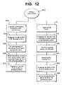
- FIG. 12is a flow chart showing a method of securing cranial bolt 100 to skull 102 of a patient.
- the methodincludes drilling a hole 104 in the skull 102 (step 500 ) and inserting a self-tapping threaded portion 200 into the hole 104 (step 502 ).
- Threaded portion 200includes mating connector 206 and an outer surface 208 having a plurality of threads 210 for engaging hole 104 .
- Lumen portion 300is engaged with threaded portion 200 (step 504 ).
- Lumen portion 300forms a fluid tight seal 306 between inner surface 202 of threaded portion 200 and stem portion 302 . The formation of the fluid tight seal 306 is described above.
- sensors 320can be introduced into sensor lumens 312 and passed into skull 102 (step 506 ).
- Further methodsinclude removing sensors 320 from lumen portion 300 and removing lumen portion 300 from threaded portion 200 (step 508 ), and engaging a second lumen portion (step 510 ).
- the second lumen portioncan have a different configuration as described above (e.g. number, shape or placement of lumens 312 ).
- FIG. 12An alternative method is shown in FIG. 12 in which, prior to the inserting step, an insertion tool 400 is engaged with threaded portion 200 (step 512 ) so as to increase the torque applied to the threaded portion during the insertion step. Threaded portion 200 is then inserted into the hole in the patient's skull (step 513 . After the inserting step, the insertion tool is removed from the threaded portion 200 (step 514 ). Then continuing, the lumen portion 300 is engaged with the threaded portion (step 515 ) and sensors 320 are inserted through the lumens into the patient's skull (step 516 ). Other methods include tapping hole 104 prior to the insertion of threaded portion 200 (step 511 ) when a threaded portion is used which is not self-tapping.
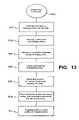
- FIG. 13illustrates a preferred embodiment of a method of using cranial bolt 100 with a floating collar 322 .
- hole 104is drilled in the skull 102 (step 500 ) and self-tapping threaded portion 200 is inserted into hole 104 (step 502 ).
- Lumen portion 300can now be rotationally adjusted, as described above, by use of floating collar 322 (step 518 ). Once the lumen portion is properly aligned, lumen portion 300 can be fixed in place and locked to threaded portion 200 (step 520 ). Similar to above, once lumen portion 300 is engaged with threaded portion 200 , sensors 320 can be introduced into sensor lumens 312 and passed into skull 102 (step 506 ). Further sensors 320 can be removed from lumen portion 300 and lumen portion 300 can be removed from threaded portion 200 (step 508 ). Finally a second lumen portion can be engaged with the threaded portion (step 510 ).
Landscapes
- Health & Medical Sciences (AREA)
- Life Sciences & Earth Sciences (AREA)
- Heart & Thoracic Surgery (AREA)
- Surgery (AREA)
- Animal Behavior & Ethology (AREA)
- General Health & Medical Sciences (AREA)
- Biomedical Technology (AREA)
- Veterinary Medicine (AREA)
- Public Health (AREA)
- Engineering & Computer Science (AREA)
- Molecular Biology (AREA)
- Pathology (AREA)
- Medical Informatics (AREA)
- Nuclear Medicine, Radiotherapy & Molecular Imaging (AREA)
- Biophysics (AREA)
- Hematology (AREA)
- Gastroenterology & Hepatology (AREA)
- Pulmonology (AREA)
- Anesthesiology (AREA)
- Neurosurgery (AREA)
- Physics & Mathematics (AREA)
- Surgical Instruments (AREA)
- External Artificial Organs (AREA)
Abstract
Description
Claims (16)
Priority Applications (7)
| Application Number | Priority Date | Filing Date | Title |
|---|---|---|---|
| US10/839,952US7604658B2 (en) | 2004-05-04 | 2004-05-04 | Multiple lumen sensor attachment |
| CA2506004ACA2506004C (en) | 2004-05-04 | 2005-04-29 | Multiple lumen sensor attachment |
| CA2934217ACA2934217A1 (en) | 2004-05-04 | 2005-04-29 | Multiple lumen sensor attachment |
| JP2005134371AJP4790303B2 (en) | 2004-05-04 | 2005-05-02 | Skull bolts secured to the patient's skull, an insertion device for inserting the threaded portion of the skull bolt into the skull, and a method for securing the skull bolt to the patient's skull |
| EP05252739AEP1593348A3 (en) | 2004-05-04 | 2005-05-03 | Multiple lumen sensor attachment |
| AU2005201870AAU2005201870B2 (en) | 2004-05-04 | 2005-05-03 | Multiple lumen sensor attachment |
| US12/556,035US8308781B2 (en) | 2004-05-04 | 2009-09-09 | Multiple lumen sensor attachment |
Applications Claiming Priority (1)
| Application Number | Priority Date | Filing Date | Title |
|---|---|---|---|
| US10/839,952US7604658B2 (en) | 2004-05-04 | 2004-05-04 | Multiple lumen sensor attachment |
Related Child Applications (1)
| Application Number | Title | Priority Date | Filing Date |
|---|---|---|---|
| US12/556,035DivisionUS8308781B2 (en) | 2004-05-04 | 2009-09-09 | Multiple lumen sensor attachment |
Publications (2)
| Publication Number | Publication Date |
|---|---|
| US20050251144A1 US20050251144A1 (en) | 2005-11-10 |
| US7604658B2true US7604658B2 (en) | 2009-10-20 |
Family
ID=34941137
Family Applications (2)
| Application Number | Title | Priority Date | Filing Date |
|---|---|---|---|
| US10/839,952Active2028-05-26US7604658B2 (en) | 2004-05-04 | 2004-05-04 | Multiple lumen sensor attachment |
| US12/556,035Expired - Fee RelatedUS8308781B2 (en) | 2004-05-04 | 2009-09-09 | Multiple lumen sensor attachment |
Family Applications After (1)
| Application Number | Title | Priority Date | Filing Date |
|---|---|---|---|
| US12/556,035Expired - Fee RelatedUS8308781B2 (en) | 2004-05-04 | 2009-09-09 | Multiple lumen sensor attachment |
Country Status (5)
| Country | Link |
|---|---|
| US (2) | US7604658B2 (en) |
| EP (1) | EP1593348A3 (en) |
| JP (1) | JP4790303B2 (en) |
| AU (1) | AU2005201870B2 (en) |
| CA (2) | CA2506004C (en) |
Cited By (17)
| Publication number | Priority date | Publication date | Assignee | Title |
|---|---|---|---|---|
| US20120078159A1 (en)* | 2010-09-29 | 2012-03-29 | Codman & Shurtleff, Inc | Multi-lumen ventricular drainage catheter |
| US20130261720A1 (en)* | 2008-12-05 | 2013-10-03 | Plugmed Heart | Housing-Interface Assembly To Be Implanted In A Bone Wall For Enabling An Interaction Between A Human Activity And A Machine |
| US8876708B1 (en)* | 2007-03-30 | 2014-11-04 | Covidien Lp | Laparoscopic port assembly |
| US20140343500A1 (en)* | 2010-02-12 | 2014-11-20 | Renishaw (Ireland) Limited | Percutaneous drug delivery apparatus |
| US9179875B2 (en) | 2009-12-21 | 2015-11-10 | Sherwin Hua | Insertion of medical devices through non-orthogonal and orthogonal trajectories within the cranium and methods of using |
| US20170291017A1 (en)* | 2014-09-23 | 2017-10-12 | Wake Forest University Health Sciences | Subdural drainage catheter with self contained mechanism for restoration of flow following catheter obstruction |
| US10258274B2 (en)* | 2013-06-20 | 2019-04-16 | Thermal Technologies, Inc. | Unitary multilumen cranial bolt |
| US10322267B2 (en) | 2013-03-15 | 2019-06-18 | Carlos A. Hakim | Externally programmable valve assembly |
| US10478265B2 (en) | 2017-03-31 | 2019-11-19 | Integra Lifesciences Corporation | Cranial fixation device |
| US10631884B2 (en) | 2017-06-05 | 2020-04-28 | Conmed Corporation | Multi-barrel drill guide |
| US10751520B2 (en) | 2006-11-23 | 2020-08-25 | Renishaw (Ireland) Limited | Neurological apparatus comprising a percutaneous access device |
| US11160580B2 (en) | 2019-04-24 | 2021-11-02 | Spine23 Inc. | Systems and methods for pedicle screw stabilization of spinal vertebrae |
| US11471173B2 (en) | 2017-06-05 | 2022-10-18 | Conmed Corporation | Multi-barrel drill guide and anchor deployment assembly |
| US11759238B2 (en) | 2008-10-01 | 2023-09-19 | Sherwin Hua | Systems and methods for pedicle screw stabilization of spinal vertebrae |
| US12076058B2 (en) | 2021-05-12 | 2024-09-03 | Spine23 Inc. | Systems and methods for pedicle screw stabilization of spinal vertebrae |
| US12268422B2 (en) | 2019-11-27 | 2025-04-08 | Spine23 Inc. | Systems, devices and methods for treating a lateral curvature of a spine |
| US12402972B2 (en) | 2022-04-28 | 2025-09-02 | Monteris Medical Corporation | Cranial access device |
Families Citing this family (56)
| Publication number | Priority date | Publication date | Assignee | Title |
|---|---|---|---|---|
| US8845711B2 (en) | 2007-10-19 | 2014-09-30 | Coherex Medical, Inc. | Medical device for modification of left atrial appendage and related systems and methods |
| US7559893B2 (en) | 1998-12-01 | 2009-07-14 | Atropos Limited | Wound retractor device |
| US9271753B2 (en) | 2002-08-08 | 2016-03-01 | Atropos Limited | Surgical device |
| US8388624B2 (en) | 2003-02-24 | 2013-03-05 | Arthrosurface Incorporated | Trochlear resurfacing system and method |
| WO2006004885A2 (en) | 2004-06-28 | 2006-01-12 | Arthrosurface, Inc. | System for articular surface replacement |
| US9820771B2 (en) | 2006-03-03 | 2017-11-21 | Axcess Instruments Inc. | Apparatus and method for minimally invasive surgery |
| US9011319B2 (en) | 2006-03-03 | 2015-04-21 | Axcess Instruments, Inc. | Conical laparoscopic apparatus for minimally invasive surgery |
| US9358029B2 (en) | 2006-12-11 | 2016-06-07 | Arthrosurface Incorporated | Retrograde resection apparatus and method |
| CA2920567C (en) | 2007-02-01 | 2019-03-05 | Ravish V. Patwardhan | Surgical navigation system for guiding an access member |
| US9687271B2 (en)* | 2007-02-23 | 2017-06-27 | Axcess Instruments, Inc. | Uniport having a one-piece body anchor and an elongated surgical instrument passageway for use in single site surgical procedures |
| DE102007008862A1 (en)* | 2007-02-23 | 2008-08-28 | Robert Bosch Gmbh | crash sensor |
| US8657740B2 (en) | 2007-06-05 | 2014-02-25 | Atropos Limited | Instrument access device |
| WO2010081039A1 (en) | 2009-01-08 | 2010-07-15 | Coherex Medical, Inc. | Medical device for modification of left atrial appendage and related systems and methods |
| WO2010121250A1 (en) | 2009-04-17 | 2010-10-21 | Arthrosurface Incorporated | Glenoid resurfacing system and method |
| US10945743B2 (en) | 2009-04-17 | 2021-03-16 | Arthrosurface Incorporated | Glenoid repair system and methods of use thereof |
| CA2765682C (en) | 2009-06-17 | 2018-07-24 | Coherex Medical, Inc. | Medical device for modification of left atrial appendage and related systems and methods |
| US9351716B2 (en) | 2009-06-17 | 2016-05-31 | Coherex Medical, Inc. | Medical device and delivery system for modification of left atrial appendage and methods thereof |
| US10064628B2 (en) | 2009-06-17 | 2018-09-04 | Coherex Medical, Inc. | Medical device for modification of left atrial appendage and related systems and methods |
| US10631969B2 (en) | 2009-06-17 | 2020-04-28 | Coherex Medical, Inc. | Medical device for modification of left atrial appendage and related systems and methods |
| US9649115B2 (en) | 2009-06-17 | 2017-05-16 | Coherex Medical, Inc. | Medical device for modification of left atrial appendage and related systems and methods |
| US9693781B2 (en) | 2009-06-17 | 2017-07-04 | Coherex Medical, Inc. | Medical device for modification of left atrial appendage and related systems and methods |
| WO2011014393A1 (en)* | 2009-07-30 | 2011-02-03 | Ethicon Endo-Surgery, Inc. | Methods and devices for providing access into a body cavity |
| WO2011033495A1 (en) | 2009-09-17 | 2011-03-24 | Atropos Limited | An instrument access device |
| EP2542165A4 (en) | 2010-03-05 | 2015-10-07 | Arthrosurface Inc | Tibial resurfacing system and method |
| GB2482337B (en)* | 2010-07-30 | 2015-10-14 | Salts Healthcare Ltd | Wound management device |
| US9675399B2 (en) | 2011-02-14 | 2017-06-13 | Michael D. Ries | Patient specific implants and instrumentation for patellar prostheses |
| EP2675399B1 (en)* | 2011-02-14 | 2016-02-03 | Ries, Michael D. | Patellar prostheses |
| WO2012119086A1 (en)* | 2011-03-02 | 2012-09-07 | Allegheny-Singer Research Institute | Device for securing drain tube |
| US9226735B2 (en)* | 2011-05-19 | 2016-01-05 | DePuy Synthes Products, Inc. | Articulating cranial bolt |
| DE102011078972A1 (en)* | 2011-07-11 | 2013-01-17 | Pajunk Gmbh & Co. Kg Besitzverwaltung | Instrument system for minimally invasive surgery |
| GB201117061D0 (en)* | 2011-10-04 | 2011-11-16 | Renishaw Ireland Ltd | Neurosurgical apparatus |
| EP2591737B1 (en)* | 2011-11-11 | 2016-11-02 | Karl Storz GmbH & Co. KG | Surgical instrument |
| EP2804565B1 (en) | 2011-12-22 | 2018-03-07 | Arthrosurface Incorporated | System for bone fixation |
| ITBA20120020U1 (en)* | 2012-04-11 | 2013-10-12 | Vincenzo Nuzziello | "DOUBLE CHANNEL SURGICAL DEVICE FOR ABDOMINAL ACCESS" |
| WO2014008126A1 (en) | 2012-07-03 | 2014-01-09 | Arthrosurface Incorporated | System and method for joint resurfacing and repair |
| US20140073859A1 (en)* | 2012-09-12 | 2014-03-13 | Codman & Shurtleff, Inc. | Low profile, multi probe, cranial fixation device and method of use |
| US9675786B2 (en)* | 2013-03-15 | 2017-06-13 | University Of Rochester | Devices, systems and methods for diverting fluid trapped in a solid organ |
| US9492200B2 (en) | 2013-04-16 | 2016-11-15 | Arthrosurface Incorporated | Suture system and method |
| US10624748B2 (en) | 2014-03-07 | 2020-04-21 | Arthrosurface Incorporated | System and method for repairing articular surfaces |
| US9931219B2 (en) | 2014-03-07 | 2018-04-03 | Arthrosurface Incorporated | Implant and anchor assembly |
| US11607319B2 (en) | 2014-03-07 | 2023-03-21 | Arthrosurface Incorporated | System and method for repairing articular surfaces |
| JP6835731B2 (en)* | 2014-11-13 | 2021-02-24 | パヴメド・インコーポレイテッドPAVMed Inc. | Intraosseous infusion port and usage |
| CN108135517A (en)* | 2015-03-13 | 2018-06-08 | 曼特瑞斯医药有限责任公司 | Neurotherapeutic device and method |
| WO2017021985A1 (en)* | 2015-08-03 | 2017-02-09 | Garaci Francesco | Guide for the intracranial positioning of cerebral catheters |
| US10368908B2 (en)* | 2015-09-15 | 2019-08-06 | Applied Medical Resources Corporation | Surgical robotic access system |
| CN107095707B (en)* | 2017-06-03 | 2023-05-26 | 成都五义医疗科技有限公司 | Puncture outfit sleeve assembly with air bag |
| WO2018231686A1 (en)* | 2017-06-12 | 2018-12-20 | The Regents Of The University Of Colorado, A Body Corporate | Cranial guide for an intracranial medical procedure |
| EP3415106B1 (en)* | 2017-06-14 | 2022-08-03 | IMEC vzw | Brain interaction apparatus, cranial anchor, and related systems |
| US11160663B2 (en) | 2017-08-04 | 2021-11-02 | Arthrosurface Incorporated | Multicomponent articular surface implant |
| WO2020186099A1 (en) | 2019-03-12 | 2020-09-17 | Arthrosurface Incorporated | Humeral and glenoid articular surface implant systems and methods |
| US11369355B2 (en) | 2019-06-17 | 2022-06-28 | Coherex Medical, Inc. | Medical device and system for occluding a tissue opening and method thereof |
| US11812969B2 (en) | 2020-12-03 | 2023-11-14 | Coherex Medical, Inc. | Medical device and system for occluding a tissue opening and method thereof |
| EP4616882A2 (en)* | 2021-04-30 | 2025-09-17 | Neurochase Technologies Limited | Implantable guide device |
| WO2023083749A1 (en)* | 2021-11-09 | 2023-05-19 | Icm (Institut Du Cerveau Et De La Moelle Épinière) | Screwing device, kit and assembly for positioning a bone anchor |
| GR1010335B (en)* | 2022-02-11 | 2022-11-09 | Αναστασιος Γεωργιου Τσογκας | Pneumocephalus prevention device |
| WO2024148262A2 (en)* | 2023-01-06 | 2024-07-11 | The Regents Of The University Of Colorado, A Body Corporate | Large lumen self-tapping evacuation port with custom high ratio thread |
Citations (56)
| Publication number | Priority date | Publication date | Assignee | Title |
|---|---|---|---|---|
| US3055370A (en) | 1958-11-28 | 1962-09-25 | William W Mckinney | Pallidotomy surgical instrument |
| US3115140A (en) | 1960-08-18 | 1963-12-24 | Baltimore Instr Company | Apparatus for stereotaxic brain operations |
| US3663965A (en) | 1970-06-08 | 1972-05-23 | Henry L Lee Jr | Bacteria-resistant percutaneous conduit device |
| US3761881A (en) | 1971-06-30 | 1973-09-25 | Ibm | Translation storage scheme for virtual memory system |
| US3995644A (en) | 1975-09-16 | 1976-12-07 | The United States Of America As Represented By The Administrator Of The National Aeronautics And Space Administration | Percutaneous connector device |
| US4004298A (en) | 1975-03-31 | 1977-01-25 | Sinai Hospital Of Detroit | Magnetically aligned releasable connector |
| US4062354A (en) | 1975-07-01 | 1977-12-13 | Taylor H Lyndon | Intracranial pressure transducer system |
| US4186728A (en) | 1977-02-18 | 1980-02-05 | U.S. Philips Corporation | Apparatus for adapting a skull for the application of a pressure transducer |
| US4233979A (en) | 1977-05-06 | 1980-11-18 | Siemens Aktiengesellschaft | Method of screwing an adapter into the human cranium |
| US4245645A (en) | 1977-09-28 | 1981-01-20 | Arseneault Pierre Michel | Self-locking cerebral electrical probe |
| US4246908A (en) | 1976-10-19 | 1981-01-27 | Kabushiki Kaisha Toyota Kenkyusho | Intracranial pressure transducer |
| US4265252A (en) | 1978-04-19 | 1981-05-05 | The Johns Hopkins University | Intracranial pressure implant |
| US4328813A (en) | 1980-10-20 | 1982-05-11 | Medtronic, Inc. | Brain lead anchoring system |
| US4350159A (en) | 1980-02-29 | 1982-09-21 | Gouda Kasim I | Frame for stereotactic surgery |
| US4354506A (en) | 1980-01-17 | 1982-10-19 | Naganokeiki Seisakujo Company, Ltd. | Intracranial pressure gauge |
| US4378809A (en) | 1978-04-13 | 1983-04-05 | Cosman Eric R | Audio-telemetric pressure sensing systems and methods |
| US4438772A (en) | 1982-04-08 | 1984-03-27 | Intech Systems Corp. | Differential stethoscope |
| US4474569A (en) | 1982-06-28 | 1984-10-02 | Denver Surgical Developments, Inc. | Antenatal shunt |
| US4494411A (en) | 1981-09-08 | 1985-01-22 | Fraunhofer-Gesellschaft Zur Forderung Der Angewandten Forschung E.V. | Pressure detector comprising a cylindrical cavity resonator having a front surface made as a diaphragm |
| US4502491A (en) | 1982-03-22 | 1985-03-05 | Hans G. Ender | Apparatus for determining the pressure between a support dressing and a body portion surrounded by said support dressing |
| US4572212A (en) | 1982-03-15 | 1986-02-25 | Paul L. Sweeney, Jr. | Subarachnoid bolts |
| US4578063A (en) | 1984-09-14 | 1986-03-25 | W. L. Gore & Assoc., Inc. | Central venous catheter |
| US4629451A (en) | 1985-09-23 | 1986-12-16 | Victory Engineering Corp. | Stereotaxic array plug |
| US4646752A (en) | 1983-04-25 | 1987-03-03 | Swann Karl W | Adjustable intracranial pressure measuring screw |
| US4705499A (en) | 1985-12-23 | 1987-11-10 | Cordis Corporation | Implantable servo valve having integral pressure sensor |
| US4805634A (en) | 1986-06-06 | 1989-02-21 | Hellige Gmbh | Adapter assembly for use with a cranial biosensor |
| US4809694A (en) | 1987-05-19 | 1989-03-07 | Ferrara Vincent L | Biopsy guide |
| US4850359A (en) | 1987-10-16 | 1989-07-25 | Ad-Tech Medical Instrument Corporation | Electrical brain-contact devices |
| US4903707A (en) | 1988-04-22 | 1990-02-27 | Camino Laboratories | Ventricular catheter assembly |
| US4955891A (en) | 1985-07-02 | 1990-09-11 | Ohio Medical Instrument Company, Inc. | Method and apparatus for performing stereotactic surgery |
| US4993425A (en) | 1988-01-05 | 1991-02-19 | Hellige Gmbh | Adapter assembly for use with a cranial biosensor |
| US4998938A (en) | 1988-06-09 | 1991-03-12 | Neurodynamics, Inc. | Removable skull mounted work platform and method of assembling same |
| US5054497A (en) | 1990-02-21 | 1991-10-08 | Biomedical Monitors And Implants, Inc. | Cranial sensor attaching device and method for its use |
| US5112312A (en) | 1991-03-14 | 1992-05-12 | Luther Medical Products, Inc. | Vascular/venous access device and method of utilizing and forming the same |
| US5127407A (en) | 1989-08-17 | 1992-07-07 | Critikon, Inc. | Epidural oxygen sensor |
| US5441481A (en) | 1994-05-27 | 1995-08-15 | Mishra; Pravin | Microdialysis probes and methods of use |
| US5464446A (en) | 1993-10-12 | 1995-11-07 | Medtronic, Inc. | Brain lead anchoring system |
| WO1996037144A1 (en) | 1995-05-26 | 1996-11-28 | White Spot Ag | Cerebral pressure measuring probe screw |
| WO1997042870A1 (en) | 1996-05-14 | 1997-11-20 | Camino Neurocare, Inc. | Expandable parenchymal bolt |
| US5718706A (en)* | 1993-06-04 | 1998-02-17 | Hip Developments Pty. Ltd. | Surgical screw and washer |
| WO1998051214A1 (en) | 1997-05-13 | 1998-11-19 | Camino Neurocare, Inc. | Expandable parenchymal bolt with lever activation |
| US5842865A (en)* | 1997-09-12 | 1998-12-01 | Sulzer Calcitek Inc. | Self-tapping implant with multiple concave tapping channels |
| US5843150A (en) | 1997-10-08 | 1998-12-01 | Medtronic, Inc. | System and method for providing electrical and/or fluid treatment within a patient's brain |
| US5865842A (en) | 1996-08-29 | 1999-02-02 | Medtronic, Inc. | System and method for anchoring brain stimulation lead or catheter |
| US5891100A (en) | 1995-01-25 | 1999-04-06 | Fleckenstein; Wolfgang | Securing device for brain scan probes |
| WO1999016349A1 (en) | 1997-09-26 | 1999-04-08 | Erik Sloth | A device for fastening in the cranial bone and a kit comprising such device |
| GB2330078A (en) | 1997-10-08 | 1999-04-14 | David Brian Ashton Hutchinson | Bolt for facilitating catheter insertion |
| US5927277A (en) | 1995-04-28 | 1999-07-27 | Medtronic, Inc. | Method and apparatus for securing probes within a burr hole |
| DE19826078C1 (en) | 1998-06-12 | 1999-08-19 | Gms | Brain measurement probe assembly |
| US6053920A (en) | 1995-10-12 | 2000-04-25 | Nobel Biocare Ab | Holder element for implantation in bone tissue |
| US6080134A (en)* | 1997-05-13 | 2000-06-27 | Camino Neurocare, Inc. | Expandable parenchymal bolt with lever activation |
| US6152933A (en) | 1997-11-12 | 2000-11-28 | Stereotaxis, Inc. | Intracranial bolt and method of placing and using an intracranial bolt to position a medical device |
| GB2355665A (en) | 1999-11-01 | 2001-05-02 | David Brian Ashton Hutchinson | Cranial bolt |
| US6356792B1 (en) | 2000-01-20 | 2002-03-12 | Electro Core Technologies, Llc | Skull mounted electrode lead securing assembly |
| US6454774B1 (en) | 1998-05-09 | 2002-09-24 | Gms Gesellschaft Fur Medizinische Sondentechnik Mbh | Device for introducing brain probes |
| US6623490B1 (en)* | 1998-10-02 | 2003-09-23 | Diametrics Medical Limited | Cranial bolt |
Family Cites Families (1)
| Publication number | Priority date | Publication date | Assignee | Title |
|---|---|---|---|---|
| IL157561A0 (en)* | 2001-03-04 | 2004-03-28 | Sterling Medivations Inc | Infusion hub assembly and fluid line disconnect system |
- 2004
- 2004-05-04USUS10/839,952patent/US7604658B2/enactiveActive
- 2005
- 2005-04-29CACA2506004Apatent/CA2506004C/ennot_activeExpired - Lifetime
- 2005-04-29CACA2934217Apatent/CA2934217A1/ennot_activeAbandoned
- 2005-05-02JPJP2005134371Apatent/JP4790303B2/ennot_activeExpired - Fee Related
- 2005-05-03EPEP05252739Apatent/EP1593348A3/ennot_activeWithdrawn
- 2005-05-03AUAU2005201870Apatent/AU2005201870B2/ennot_activeCeased
- 2009
- 2009-09-09USUS12/556,035patent/US8308781B2/ennot_activeExpired - Fee Related
Patent Citations (58)
| Publication number | Priority date | Publication date | Assignee | Title |
|---|---|---|---|---|
| US3055370A (en) | 1958-11-28 | 1962-09-25 | William W Mckinney | Pallidotomy surgical instrument |
| US3115140A (en) | 1960-08-18 | 1963-12-24 | Baltimore Instr Company | Apparatus for stereotaxic brain operations |
| US3663965A (en) | 1970-06-08 | 1972-05-23 | Henry L Lee Jr | Bacteria-resistant percutaneous conduit device |
| US3761881A (en) | 1971-06-30 | 1973-09-25 | Ibm | Translation storage scheme for virtual memory system |
| US4004298A (en) | 1975-03-31 | 1977-01-25 | Sinai Hospital Of Detroit | Magnetically aligned releasable connector |
| US4062354A (en) | 1975-07-01 | 1977-12-13 | Taylor H Lyndon | Intracranial pressure transducer system |
| US3995644A (en) | 1975-09-16 | 1976-12-07 | The United States Of America As Represented By The Administrator Of The National Aeronautics And Space Administration | Percutaneous connector device |
| US4246908A (en) | 1976-10-19 | 1981-01-27 | Kabushiki Kaisha Toyota Kenkyusho | Intracranial pressure transducer |
| US4186728A (en) | 1977-02-18 | 1980-02-05 | U.S. Philips Corporation | Apparatus for adapting a skull for the application of a pressure transducer |
| US4233979A (en) | 1977-05-06 | 1980-11-18 | Siemens Aktiengesellschaft | Method of screwing an adapter into the human cranium |
| US4245645A (en) | 1977-09-28 | 1981-01-20 | Arseneault Pierre Michel | Self-locking cerebral electrical probe |
| US4378809A (en) | 1978-04-13 | 1983-04-05 | Cosman Eric R | Audio-telemetric pressure sensing systems and methods |
| US4265252A (en) | 1978-04-19 | 1981-05-05 | The Johns Hopkins University | Intracranial pressure implant |
| US4354506A (en) | 1980-01-17 | 1982-10-19 | Naganokeiki Seisakujo Company, Ltd. | Intracranial pressure gauge |
| US4350159A (en) | 1980-02-29 | 1982-09-21 | Gouda Kasim I | Frame for stereotactic surgery |
| US4328813A (en) | 1980-10-20 | 1982-05-11 | Medtronic, Inc. | Brain lead anchoring system |
| US4494411A (en) | 1981-09-08 | 1985-01-22 | Fraunhofer-Gesellschaft Zur Forderung Der Angewandten Forschung E.V. | Pressure detector comprising a cylindrical cavity resonator having a front surface made as a diaphragm |
| US4572212A (en) | 1982-03-15 | 1986-02-25 | Paul L. Sweeney, Jr. | Subarachnoid bolts |
| US4502491A (en) | 1982-03-22 | 1985-03-05 | Hans G. Ender | Apparatus for determining the pressure between a support dressing and a body portion surrounded by said support dressing |
| US4438772A (en) | 1982-04-08 | 1984-03-27 | Intech Systems Corp. | Differential stethoscope |
| US4474569A (en) | 1982-06-28 | 1984-10-02 | Denver Surgical Developments, Inc. | Antenatal shunt |
| US4646752A (en) | 1983-04-25 | 1987-03-03 | Swann Karl W | Adjustable intracranial pressure measuring screw |
| US4578063A (en) | 1984-09-14 | 1986-03-25 | W. L. Gore & Assoc., Inc. | Central venous catheter |
| US4955891A (en) | 1985-07-02 | 1990-09-11 | Ohio Medical Instrument Company, Inc. | Method and apparatus for performing stereotactic surgery |
| US4629451A (en) | 1985-09-23 | 1986-12-16 | Victory Engineering Corp. | Stereotaxic array plug |
| US4705499A (en) | 1985-12-23 | 1987-11-10 | Cordis Corporation | Implantable servo valve having integral pressure sensor |
| US4805634A (en) | 1986-06-06 | 1989-02-21 | Hellige Gmbh | Adapter assembly for use with a cranial biosensor |
| US4809694A (en) | 1987-05-19 | 1989-03-07 | Ferrara Vincent L | Biopsy guide |
| US4850359A (en) | 1987-10-16 | 1989-07-25 | Ad-Tech Medical Instrument Corporation | Electrical brain-contact devices |
| US4993425A (en) | 1988-01-05 | 1991-02-19 | Hellige Gmbh | Adapter assembly for use with a cranial biosensor |
| US4903707A (en) | 1988-04-22 | 1990-02-27 | Camino Laboratories | Ventricular catheter assembly |
| US4998938A (en) | 1988-06-09 | 1991-03-12 | Neurodynamics, Inc. | Removable skull mounted work platform and method of assembling same |
| US5127407A (en) | 1989-08-17 | 1992-07-07 | Critikon, Inc. | Epidural oxygen sensor |
| US5054497A (en) | 1990-02-21 | 1991-10-08 | Biomedical Monitors And Implants, Inc. | Cranial sensor attaching device and method for its use |
| US5112312A (en) | 1991-03-14 | 1992-05-12 | Luther Medical Products, Inc. | Vascular/venous access device and method of utilizing and forming the same |
| US5718706A (en)* | 1993-06-04 | 1998-02-17 | Hip Developments Pty. Ltd. | Surgical screw and washer |
| US5464446A (en) | 1993-10-12 | 1995-11-07 | Medtronic, Inc. | Brain lead anchoring system |
| US5441481A (en) | 1994-05-27 | 1995-08-15 | Mishra; Pravin | Microdialysis probes and methods of use |
| US5891100A (en) | 1995-01-25 | 1999-04-06 | Fleckenstein; Wolfgang | Securing device for brain scan probes |
| US5927277A (en) | 1995-04-28 | 1999-07-27 | Medtronic, Inc. | Method and apparatus for securing probes within a burr hole |
| WO1996037144A1 (en) | 1995-05-26 | 1996-11-28 | White Spot Ag | Cerebral pressure measuring probe screw |
| US6053920A (en) | 1995-10-12 | 2000-04-25 | Nobel Biocare Ab | Holder element for implantation in bone tissue |
| WO1997042870A1 (en) | 1996-05-14 | 1997-11-20 | Camino Neurocare, Inc. | Expandable parenchymal bolt |
| US5865842A (en) | 1996-08-29 | 1999-02-02 | Medtronic, Inc. | System and method for anchoring brain stimulation lead or catheter |
| US6080134A (en)* | 1997-05-13 | 2000-06-27 | Camino Neurocare, Inc. | Expandable parenchymal bolt with lever activation |
| WO1998051214A1 (en) | 1997-05-13 | 1998-11-19 | Camino Neurocare, Inc. | Expandable parenchymal bolt with lever activation |
| US5842865A (en)* | 1997-09-12 | 1998-12-01 | Sulzer Calcitek Inc. | Self-tapping implant with multiple concave tapping channels |
| WO1999016349A1 (en) | 1997-09-26 | 1999-04-08 | Erik Sloth | A device for fastening in the cranial bone and a kit comprising such device |
| US6432058B1 (en) | 1997-09-26 | 2002-08-13 | Erik Sloth | Device for fastening in the cranial bone and a kit comprising such device |
| GB2330078A (en) | 1997-10-08 | 1999-04-14 | David Brian Ashton Hutchinson | Bolt for facilitating catheter insertion |
| GB2330080A (en) | 1997-10-08 | 1999-04-14 | David Brian Ashton Hutchinson | Bolt facilitating catheter insertion into the brain |
| US5843150A (en) | 1997-10-08 | 1998-12-01 | Medtronic, Inc. | System and method for providing electrical and/or fluid treatment within a patient's brain |
| US6152933A (en) | 1997-11-12 | 2000-11-28 | Stereotaxis, Inc. | Intracranial bolt and method of placing and using an intracranial bolt to position a medical device |
| US6454774B1 (en) | 1998-05-09 | 2002-09-24 | Gms Gesellschaft Fur Medizinische Sondentechnik Mbh | Device for introducing brain probes |
| DE19826078C1 (en) | 1998-06-12 | 1999-08-19 | Gms | Brain measurement probe assembly |
| US6623490B1 (en)* | 1998-10-02 | 2003-09-23 | Diametrics Medical Limited | Cranial bolt |
| GB2355665A (en) | 1999-11-01 | 2001-05-02 | David Brian Ashton Hutchinson | Cranial bolt |
| US6356792B1 (en) | 2000-01-20 | 2002-03-12 | Electro Core Technologies, Llc | Skull mounted electrode lead securing assembly |
Cited By (30)
| Publication number | Priority date | Publication date | Assignee | Title |
|---|---|---|---|---|
| US11717663B2 (en) | 2006-11-23 | 2023-08-08 | Renishaw (Ireland) Limited | Neurological apparatus comprising a percutaneous access device |
| US10751520B2 (en) | 2006-11-23 | 2020-08-25 | Renishaw (Ireland) Limited | Neurological apparatus comprising a percutaneous access device |
| US8876708B1 (en)* | 2007-03-30 | 2014-11-04 | Covidien Lp | Laparoscopic port assembly |
| US9314267B2 (en) | 2007-03-30 | 2016-04-19 | Covidien Lp | Laparoscopic port assembly |
| US11759238B2 (en) | 2008-10-01 | 2023-09-19 | Sherwin Hua | Systems and methods for pedicle screw stabilization of spinal vertebrae |
| US20130261720A1 (en)* | 2008-12-05 | 2013-10-03 | Plugmed Heart | Housing-Interface Assembly To Be Implanted In A Bone Wall For Enabling An Interaction Between A Human Activity And A Machine |
| US9179875B2 (en) | 2009-12-21 | 2015-11-10 | Sherwin Hua | Insertion of medical devices through non-orthogonal and orthogonal trajectories within the cranium and methods of using |
| US9642552B2 (en) | 2009-12-21 | 2017-05-09 | Sherwin Hua | Insertion of medical devices through non-orthogonal and orthogonal trajectories within the cranium and methods of using |
| US9820668B2 (en) | 2009-12-21 | 2017-11-21 | Sherwin Hua | Insertion of medical devices through non-orthogonal and orthogonal trajectories within the cranium and methods of using |
| US10736533B2 (en) | 2009-12-21 | 2020-08-11 | Sherwin Hua | Insertion of medical devices through non-orthogonal and orthogonal trajectories within the cranium and methods of using |
| US11826536B2 (en)* | 2010-02-12 | 2023-11-28 | Renishaw (Ireland) Limited | Percutaneous drug delivery apparatus |
| US10507316B2 (en) | 2010-02-12 | 2019-12-17 | Renishaw (Ireland) Limited | Implantable fluid router |
| US10596362B2 (en)* | 2010-02-12 | 2020-03-24 | Renishaw (Ireland) Limited | Percutaneous drug delivery apparatus |
| US20200215318A1 (en)* | 2010-02-12 | 2020-07-09 | Renishaw (Ireland) Limited | Percutaneous drug delivery apparatus |
| US20140343500A1 (en)* | 2010-02-12 | 2014-11-20 | Renishaw (Ireland) Limited | Percutaneous drug delivery apparatus |
| US10232151B2 (en) | 2010-09-29 | 2019-03-19 | Integra Lifesciences Switzerland Sàrl | Multi-lumen ventricular drainage catheter |
| US20120078159A1 (en)* | 2010-09-29 | 2012-03-29 | Codman & Shurtleff, Inc | Multi-lumen ventricular drainage catheter |
| US10322267B2 (en) | 2013-03-15 | 2019-06-18 | Carlos A. Hakim | Externally programmable valve assembly |
| US12427292B2 (en) | 2013-03-15 | 2025-09-30 | Ceredyn Biotechnology Llc | Externally programmable valve assembly |
| US11311704B2 (en) | 2013-03-15 | 2022-04-26 | Ceredyn Biotechnology Llc | Externally programmable valve assembly |
| US10258274B2 (en)* | 2013-06-20 | 2019-04-16 | Thermal Technologies, Inc. | Unitary multilumen cranial bolt |
| US20170291017A1 (en)* | 2014-09-23 | 2017-10-12 | Wake Forest University Health Sciences | Subdural drainage catheter with self contained mechanism for restoration of flow following catheter obstruction |
| US10478265B2 (en) | 2017-03-31 | 2019-11-19 | Integra Lifesciences Corporation | Cranial fixation device |
| US11471173B2 (en) | 2017-06-05 | 2022-10-18 | Conmed Corporation | Multi-barrel drill guide and anchor deployment assembly |
| US11344321B2 (en) | 2017-06-05 | 2022-05-31 | Conmed Corporation | Multi-barrel drill guide |
| US10631884B2 (en) | 2017-06-05 | 2020-04-28 | Conmed Corporation | Multi-barrel drill guide |
| US11160580B2 (en) | 2019-04-24 | 2021-11-02 | Spine23 Inc. | Systems and methods for pedicle screw stabilization of spinal vertebrae |
| US12268422B2 (en) | 2019-11-27 | 2025-04-08 | Spine23 Inc. | Systems, devices and methods for treating a lateral curvature of a spine |
| US12076058B2 (en) | 2021-05-12 | 2024-09-03 | Spine23 Inc. | Systems and methods for pedicle screw stabilization of spinal vertebrae |
| US12402972B2 (en) | 2022-04-28 | 2025-09-02 | Monteris Medical Corporation | Cranial access device |
Also Published As
| Publication number | Publication date |
|---|---|
| EP1593348A2 (en) | 2005-11-09 |
| CA2934217A1 (en) | 2005-11-05 |
| US20090326519A1 (en) | 2009-12-31 |
| US8308781B2 (en) | 2012-11-13 |
| CA2506004A1 (en) | 2005-11-05 |
| CA2506004C (en) | 2017-03-07 |
| AU2005201870B2 (en) | 2011-06-30 |
| EP1593348A3 (en) | 2005-11-16 |
| JP4790303B2 (en) | 2011-10-12 |
| JP2005324017A (en) | 2005-11-24 |
| US20050251144A1 (en) | 2005-11-10 |
| AU2005201870A1 (en) | 2005-11-24 |
Similar Documents
| Publication | Publication Date | Title |
|---|---|---|
| US7604658B2 (en) | Multiple lumen sensor attachment | |
| US9039615B2 (en) | Method and apparatus for directed device placement in the cerebral ventricles or other intracranial targets | |
| EP3669812B1 (en) | Universal navigation instrument adapter | |
| US4646752A (en) | Adjustable intracranial pressure measuring screw | |
| US9901713B2 (en) | Low profile instrument immobilizer | |
| US6368330B1 (en) | Apparatus for frameless stereotactic surgery | |
| US4998938A (en) | Removable skull mounted work platform and method of assembling same | |
| JP4127962B2 (en) | Device for adjusting a stereotactic and endoscopically arranged appliance | |
| US10258274B2 (en) | Unitary multilumen cranial bolt | |
| CN104411258B (en) | Skull Drill System | |
| US20030073934A1 (en) | Double slotted-cannula device and method of use | |
| US20040015133A1 (en) | Epidural apparatus | |
| EP1549241B1 (en) | Low profile instrument immobilizer | |
| US4600013A (en) | Intracranial pressure monitoring probe | |
| WO1983003190A1 (en) | Subarachnoid bolts | |
| AU2018302016A1 (en) | Trajectory array guide system | |
| US4572212A (en) | Subarachnoid bolts | |
| US20240207010A1 (en) | Implantable guide device | |
| US20230310816A1 (en) | Surgical method, device, system and kit for the treatment of hydrocephalus | |
| CN217244636U (en) | Depth limiting device and bone drill | |
| US20230263515A1 (en) | Implant assembly and method for accessing dural venous sinus or other fluids inside the cranium |
Legal Events
| Date | Code | Title | Description |
|---|---|---|---|
| AS | Assignment | Owner name:CODMAN & SHURTLEFF, INC., MASSACHUSETTS Free format text:ASSIGNMENT OF ASSIGNORS INTEREST;ASSIGNORS:WILSON, STEPHEN F.;GORHAN, MICHAEL C.;REEL/FRAME:015307/0755 Effective date:20040430 | |
| STCF | Information on status: patent grant | Free format text:PATENTED CASE | |
| CC | Certificate of correction | ||
| FPAY | Fee payment | Year of fee payment:4 | |
| FPAY | Fee payment | Year of fee payment:8 | |
| AS | Assignment | Owner name:DEPUY SPINE, LLC, MASSACHUSETTS Free format text:ASSIGNMENT OF ASSIGNORS INTEREST;ASSIGNOR:CODMAN & SHURTLEFF, INC.;REEL/FRAME:045058/0627 Effective date:20121230 | |
| AS | Assignment | Owner name:HAND INNOVATIONS LLC, FLORIDA Free format text:ASSIGNMENT OF ASSIGNORS INTEREST;ASSIGNOR:DEPUY SPINE, LLC;REEL/FRAME:045074/0943 Effective date:20121230 Owner name:DEPUY SYNTHES PRODUCTS, LLC, MASSACHUSETTS Free format text:CHANGE OF NAME;ASSIGNOR:HAND INNOVATIONS LLC;REEL/FRAME:045476/0712 Effective date:20121231 Owner name:DEPUY SYNTHES PRODUCTS, INC., INDIANA Free format text:CHANGE OF NAME;ASSIGNOR:DEPUY SYNTHES PRODUCTS, LLC;REEL/FRAME:045479/0763 Effective date:20141219 | |
| AS | Assignment | Owner name:INTEGRA LIFESCIENCES CORPORATION, NEW JERSEY Free format text:ASSIGNMENT OF ASSIGNORS INTEREST;ASSIGNOR:DEPUY SYNTHES PRODUCTS, INC.;REEL/FRAME:045180/0382 Effective date:20171002 | |
| MAFP | Maintenance fee payment | Free format text:PAYMENT OF MAINTENANCE FEE, 12TH YEAR, LARGE ENTITY (ORIGINAL EVENT CODE: M1553); ENTITY STATUS OF PATENT OWNER: LARGE ENTITY Year of fee payment:12 |