US7604617B2 - Percutaneously implantable medical device configured to promote tissue ingrowth - Google Patents
Percutaneously implantable medical device configured to promote tissue ingrowthDownload PDFInfo
- Publication number
- US7604617B2 US7604617B2US10/821,383US82138304AUS7604617B2US 7604617 B2US7604617 B2US 7604617B2US 82138304 AUS82138304 AUS 82138304AUS 7604617 B2US7604617 B2US 7604617B2
- Authority
- US
- United States
- Prior art keywords
- stud
- porous layer
- peripheral surface
- medical device
- housing body
- Prior art date
- Legal status (The legal status is an assumption and is not a legal conclusion. Google has not performed a legal analysis and makes no representation as to the accuracy of the status listed.)
- Expired - Lifetime, expires
Links
- 230000002093peripheral effectEffects0.000claimsabstractdescription31
- 230000001737promoting effectEffects0.000claimsabstractdescription13
- 210000004872soft tissueAnatomy0.000claimsabstractdescription9
- 239000000835fiberSubstances0.000claimsdescription13
- 238000002513implantationMethods0.000claimsdescription12
- 210000000613ear canalAnatomy0.000claimsdescription10
- 238000000034methodMethods0.000claimsdescription10
- 239000000463materialSubstances0.000claimsdescription9
- 239000011148porous materialSubstances0.000claimsdescription8
- RTAQQCXQSZGOHL-UHFFFAOYSA-NTitaniumChemical compound[Ti]RTAQQCXQSZGOHL-UHFFFAOYSA-N0.000claimsdescription6
- 239000010936titaniumSubstances0.000claimsdescription6
- 229910052719titaniumInorganic materials0.000claimsdescription6
- BQCADISMDOOEFD-UHFFFAOYSA-NSilverChemical compound[Ag]BQCADISMDOOEFD-UHFFFAOYSA-N0.000claimsdescription5
- 229910000971Silver steelInorganic materials0.000claimsdescription5
- 239000007769metal materialSubstances0.000claimsdescription5
- HLXZNVUGXRDIFK-UHFFFAOYSA-Nnickel titaniumChemical compound[Ti].[Ti].[Ti].[Ti].[Ti].[Ti].[Ti].[Ti].[Ti].[Ti].[Ti].[Ni].[Ni].[Ni].[Ni].[Ni].[Ni].[Ni].[Ni].[Ni].[Ni].[Ni].[Ni].[Ni].[Ni]HLXZNVUGXRDIFK-UHFFFAOYSA-N0.000claimsdescription5
- 229910001000nickel titaniumInorganic materials0.000claimsdescription5
- 239000004332silverSubstances0.000claimsdescription5
- 229910001220stainless steelInorganic materials0.000claimsdescription5
- 239000010935stainless steelSubstances0.000claimsdescription5
- 230000005641tunnelingEffects0.000claimsdescription4
- 238000007920subcutaneous administrationMethods0.000claims2
- 208000002925dental cariesDiseases0.000claims1
- 210000001519tissueAnatomy0.000abstractdescription21
- 208000015181infectious diseaseDiseases0.000abstractdescription13
- 230000004888barrier functionEffects0.000abstractdescription10
- 238000004873anchoringMethods0.000abstractdescription8
- 239000000758substrateSubstances0.000abstractdescription3
- 230000002500effect on skinEffects0.000abstractdescription2
- 210000003491skinAnatomy0.000description12
- 230000035876healingEffects0.000description6
- 239000000126substanceSubstances0.000description6
- 229920004934Dacron®Polymers0.000description3
- 206010061218InflammationDiseases0.000description3
- 239000003795chemical substances by applicationSubstances0.000description3
- 210000004207dermisAnatomy0.000description3
- 210000002615epidermisAnatomy0.000description3
- 230000004054inflammatory processEffects0.000description3
- 239000005020polyethylene terephthalateSubstances0.000description3
- 238000004804windingMethods0.000description3
- 239000004677NylonSubstances0.000description2
- 239000004809TeflonSubstances0.000description2
- 229920006362Teflon®Polymers0.000description2
- 239000000853adhesiveSubstances0.000description2
- 230000001070adhesive effectEffects0.000description2
- 239000003242anti bacterial agentSubstances0.000description2
- 229940088710antibiotic agentDrugs0.000description2
- 239000000560biocompatible materialSubstances0.000description2
- -1e.g.Substances0.000description2
- 239000007943implantSubstances0.000description2
- 229910052751metalInorganic materials0.000description2
- 239000002184metalSubstances0.000description2
- 229920001778nylonPolymers0.000description2
- 230000000149penetrating effectEffects0.000description2
- 229920000098polyolefinPolymers0.000description2
- 229920001296polysiloxanePolymers0.000description2
- 229940100890silver compoundDrugs0.000description2
- 150000003379silver compoundsChemical class0.000description2
- 150000003431steroidsChemical class0.000description2
- 230000002792vascularEffects0.000description2
- 241000894006BacteriaSpecies0.000description1
- 210000000683abdominal cavityAnatomy0.000description1
- 230000002411adverseEffects0.000description1
- 230000008901benefitEffects0.000description1
- 230000015572biosynthetic processEffects0.000description1
- 210000000988bone and boneAnatomy0.000description1
- 239000002657fibrous materialSubstances0.000description1
- 230000006870functionEffects0.000description1
- 210000003128headAnatomy0.000description1
- 239000000203mixtureSubstances0.000description1
- 238000012986modificationMethods0.000description1
- 230000004048modificationEffects0.000description1
- 231100000435percutaneous penetrationToxicity0.000description1
- 230000004044responseEffects0.000description1
- 230000000153supplemental effectEffects0.000description1
- 238000001356surgical procedureMethods0.000description1
- 230000008467tissue growthEffects0.000description1
Images


Classifications
- A—HUMAN NECESSITIES
- A61—MEDICAL OR VETERINARY SCIENCE; HYGIENE
- A61M—DEVICES FOR INTRODUCING MEDIA INTO, OR ONTO, THE BODY; DEVICES FOR TRANSDUCING BODY MEDIA OR FOR TAKING MEDIA FROM THE BODY; DEVICES FOR PRODUCING OR ENDING SLEEP OR STUPOR
- A61M39/00—Tubes, tube connectors, tube couplings, valves, access sites or the like, specially adapted for medical use
- A61M39/02—Access sites
- A61M39/0247—Semi-permanent or permanent transcutaneous or percutaneous access sites to the inside of the body
- A—HUMAN NECESSITIES
- A61—MEDICAL OR VETERINARY SCIENCE; HYGIENE
- A61F—FILTERS IMPLANTABLE INTO BLOOD VESSELS; PROSTHESES; DEVICES PROVIDING PATENCY TO, OR PREVENTING COLLAPSING OF, TUBULAR STRUCTURES OF THE BODY, e.g. STENTS; ORTHOPAEDIC, NURSING OR CONTRACEPTIVE DEVICES; FOMENTATION; TREATMENT OR PROTECTION OF EYES OR EARS; BANDAGES, DRESSINGS OR ABSORBENT PADS; FIRST-AID KITS
- A61F2/00—Filters implantable into blood vessels; Prostheses, i.e. artificial substitutes or replacements for parts of the body; Appliances for connecting them with the body; Devices providing patency to, or preventing collapsing of, tubular structures of the body, e.g. stents
- A61F2/0077—Special surfaces of prostheses, e.g. for improving ingrowth
- A—HUMAN NECESSITIES
- A61—MEDICAL OR VETERINARY SCIENCE; HYGIENE
- A61L—METHODS OR APPARATUS FOR STERILISING MATERIALS OR OBJECTS IN GENERAL; DISINFECTION, STERILISATION OR DEODORISATION OF AIR; CHEMICAL ASPECTS OF BANDAGES, DRESSINGS, ABSORBENT PADS OR SURGICAL ARTICLES; MATERIALS FOR BANDAGES, DRESSINGS, ABSORBENT PADS OR SURGICAL ARTICLES
- A61L29/00—Materials for catheters, medical tubing, cannulae, or endoscopes or for coating catheters
- A61L29/14—Materials characterised by their function or physical properties, e.g. lubricating compositions
- A61L29/146—Porous materials, e.g. foams or sponges
- H—ELECTRICITY
- H04—ELECTRIC COMMUNICATION TECHNIQUE
- H04R—LOUDSPEAKERS, MICROPHONES, GRAMOPHONE PICK-UPS OR LIKE ACOUSTIC ELECTROMECHANICAL TRANSDUCERS; DEAF-AID SETS; PUBLIC ADDRESS SYSTEMS
- H04R25/00—Deaf-aid sets, i.e. electro-acoustic or electro-mechanical hearing aids; Electric tinnitus maskers providing an auditory perception
- H04R25/65—Housing parts, e.g. shells, tips or moulds, or their manufacture
- A—HUMAN NECESSITIES
- A61—MEDICAL OR VETERINARY SCIENCE; HYGIENE
- A61M—DEVICES FOR INTRODUCING MEDIA INTO, OR ONTO, THE BODY; DEVICES FOR TRANSDUCING BODY MEDIA OR FOR TAKING MEDIA FROM THE BODY; DEVICES FOR PRODUCING OR ENDING SLEEP OR STUPOR
- A61M39/00—Tubes, tube connectors, tube couplings, valves, access sites or the like, specially adapted for medical use
- A61M39/02—Access sites
- A61M39/0247—Semi-permanent or permanent transcutaneous or percutaneous access sites to the inside of the body
- A61M2039/0261—Means for anchoring port to the body, or ports having a special shape or being made of a specific material to allow easy implantation/integration in the body
- H—ELECTRICITY
- H04—ELECTRIC COMMUNICATION TECHNIQUE
- H04R—LOUDSPEAKERS, MICROPHONES, GRAMOPHONE PICK-UPS OR LIKE ACOUSTIC ELECTROMECHANICAL TRANSDUCERS; DEAF-AID SETS; PUBLIC ADDRESS SYSTEMS
- H04R2225/00—Details of deaf aids covered by H04R25/00, not provided for in any of its subgroups
- H04R2225/67—Implantable hearing aids or parts thereof not covered by H04R25/606
- H—ELECTRICITY
- H04—ELECTRIC COMMUNICATION TECHNIQUE
- H04R—LOUDSPEAKERS, MICROPHONES, GRAMOPHONE PICK-UPS OR LIKE ACOUSTIC ELECTROMECHANICAL TRANSDUCERS; DEAF-AID SETS; PUBLIC ADDRESS SYSTEMS
- H04R25/00—Deaf-aid sets, i.e. electro-acoustic or electro-mechanical hearing aids; Electric tinnitus maskers providing an auditory perception
- H04R25/65—Housing parts, e.g. shells, tips or moulds, or their manufacture
- H04R25/658—Manufacture of housing parts
Definitions
- This inventionrelates generally to medical devices intended to be surgically implanted in a patient's body. More particularly, the invention is directed to an implantable percutaneous device, and method of implantation, especially configured to promote soft tissue ingrowth for creating an infection resistant barrier and for anchoring the implanted device in place.
- a porous outer surfacecan be used on an implantable medical device to promote bone ingrowth to facilitate device anchoring. It has also been suggested that the application of a porous surface to a percutaneous implantable device can be helpful for promoting tissue ingrowth. For example, see European Patent Publication 0367354B1 published Sep. 5, 1990 entitled “A percutaneous implant”. It is also noted that so called “dacron cuffs” have been used to accommodate tissue ingrowth for anchoring percutaneous catheters.
- the present inventionis directed generally to medical devices and more particularly to a structural configuration and method of implantation for promoting tissue ingrowth around a percutaneously projecting portion, or stud, of the medical device so as to create an infection resistant barrier, provide effective anchoring and inhibit marsupialization (which reduces vascularization of the local tissue).
- An implantable device in accordance with the inventionincludes a housing having a projecting stud defining an outer end and a peripheral surface extending longitudinally inwardly from said outer end.
- a longitudinally extending porous peripheral layeris formed on the peripheral surface characterized by a porosity conducive to promoting tissue ingrowth.
- the studprojects through a skin incision and places the porous peripheral layer adjacent to the skin surrounding the incision.
- the deviceis intended to be implanted so that the porous layer is oriented substantially perpendicular to the patent's skin plane adjacent to the incision site and extends longitudinally below the skin surface.
- a porous layer in accordance with the inventionis preferably formed by mounting a layer of fibrous material on the projecting stud of the implantable device housing.
- the fibrous layeris preferably fabricated from bio compatible metallic materials, such as titanium, nitinol, silver, or stainless steel, or from polymeric materials, such as polyolefins, Teflon, nylon, Dacron, or silicone. Fibers can be wound directly onto the housing stud or alternatively a separate structure (e.g., mesh or sintered polymeric or metallic material) can be fabricated and then attached to the stud using mechanical or adhesive techniques. To adequately promote soft tissue ingrowth, the resulting fibrous layer should preferably contain pore sizes on the order of 50 to 200 microns with a porosity of 60 to 95%.
- a preferred implantable device in accordance with the inventionincludes a housing having a stud projecting percutaneously through an incision in the patient's skin.
- the studdefines a peripheral surface extending longitudinally inwardly from the stud outer end.
- the longitudinal peripheral surfaceis used as a substrate to carry the aforementioned fibrous layer.
- the peripheral fibrous layeris located so that when implanted, it extends to below the patient's epidermal and dermal skin layers for promoting laterally directed soft tissue ingrowth.
- the housingalso defines a lateral shoulder surface oriented substantially perpendicular to the longitudinal peripheral surface.
- the shoulder surfacewhen implanted, is located just inwardly from the patient's outer skin surface.
- the shoulder surfacealso carries a porous layer conducive to promoting tissue ingrowth.
- Embodiments of the inventioncan be advantageously used with a wide variety of medical devices adapted for percutaneous implantation.
- such devicesinclude implantable hearing aids which can percutaneously project into the ear canal and catheters, cables, and/or sensors which can project percutaneously to provide access to various internal sites, e.g., access to the abdominal cavity, to the inner eye, to the circulatory system, etc.
- FIG. 1schematically depicts an exemplary medical device (i.e., a hearing aid, percutaneously implanted in a patient's ear canal) which can advantageously utilize the teachings of the present invention
- FIG. 2is an enlarged schematic representation showing a conventional medical device penetrating the epidermis and dermis skin layers shortly after implantation;
- FIG. 3is a schematic representation similar to FIG. 2 showing skin downgrowth around the conventional medical device typically occurring after implantation;
- FIG. 4schematically shows part of a device housing having a portion, or stud, adapted to project percutaneously in accordance with the invention having longitudinally and laterally extending surfaces for respectively supporting porous layers;
- FIG. 5is a side sectional view of the device housing of FIG. 4 also showing an optional end cap;
- FIG. 6is an enlarged schematic representation of a fibrous mesh which can form a porous layer in accordance with the invention.
- FIG. 7is similar to FIG. 5 but additionally represents the inclusion of an optional supplemental agent for cooperating with the porous layer to promote tissue healing and/or resist infection and inflammation;
- FIG. 8is a schematic representation similar to FIG. 3 but representing tissue ingrowth into the interstices of longitudinal and lateral porous layers in accordance with the present invention
- FIGS. 9A-9Dillustrate various configurations showing the use of a transitional surface installed on a housing stud to beneficially modify healing
- FIG. 10schematically depicts the use of an invention embodiment in a vascular application where a catheter, cable, or sensor extends percutaneously through the patient's skin layers;
- FIG. 11schematically depicts the use of an invention embodiment in an ocular application for providing access to the inner eye via a percutaneous catheter, cable, or sensor;
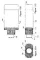
- FIG. 12is an isometric view of one preferred embodiment of the invention intended for implanting adjacent to a patient's ear canal to promote hearing (as generally depicted in FIG. 1 );
- FIGS. 13A , 13 B, and 13 Crespectively show top, side, and end views of the device of FIG. 12 .
- FIG. 1schematically depicts an exemplary application of the teachings of the invention.
- FIG. 1represents a fragmentary front view of a patient's head 20 (i.e., as seen when looking at the patient's face) showing the patient's ear 22 , pinna 24 (sometimes referred to as “auricle”), and an ear canal 26 .
- the soft tissue space behind the pinna 24is often referred to as the retro-auricular space or cavity 28 .
- FIG. 1also depicts a generic hearing aid 30 implanted within a recess 32 behind the patient's ear canal 26 .
- the recess 32can be readily formed by a relatively simple surgical procedure involving for example, tunneling through the space 28 .
- the recessnominally extends from a proximal end 36 to a distal end 38 located at an incision site 40 opening into the ear canal 26 .
- the hearing aid 30 depicted in FIG. 1is comprised of a generally elongate, e.g., cylindrical, tubular housing 42 having a proximal end 44 and a distal end 46 .
- the housing 42is preferably formed of a biocompatible material, e.g., titanium.
- the tubular housing 42typically contains electronic circuitry for driving a sound generator, i.e., an electroacoustic transducer (not shown) located within the housing proximate to the distal end 46 .
- a sound generatori.e., an electroacoustic transducer (not shown) located within the housing proximate to the distal end 46 .
- the housing distal endas shown in FIG. 1 , preferably projects percutaneously through the incision site 40 into the ear canal 26 to locate the transducer in or immediately adjacent to the ear canal.
- FIG. 2schematically depicts the housing distal end 46 in greater detail generally showing the formation of the patient's skin layers 50 (i.e., dermis 54 and epidermis 56 ) adjacent to the incision site 40 , shortly after implantation of the housing 42 .
- FIG. 3schematically illustrates how, in a typical prior art implantation, the epidermis 56 and other tissue layers, over a period of time, can grow downwardly along the longitudinal surface 58 of the housing 42 . This tissue downgrowth, as depicted in FIG. 3 , tends to produce sinus tracts 59 , susceptible for infection. Continued downgrowth can lead to marsupialization and ultimately can result in expulsion of the implant, e.g. hearing aid 30 , from the patient's body.
- the implante.g. hearing aid 30
- the present inventionis directed primarily to means for creating an infection resistant barrier around the housing distal end 46 at the percutaneous penetration, i.e., incision, site 40 in order to effectively anchor the implanted device and avoid the aforementioned problems associated with tissue downgrowth.
- the infection resistant barrieris formed by promoting tissue ingrowth into a porous layer(s) formed on orthogonal (longitudinal and lateral) surfaces of the housing 42 .
- FIGS. 4 and 5illustrate a preferred manner of configuring the housing distal end 46 in accordance with the present invention.
- the housing 42includes a lateral shoulder 60 which forms a reduced diameter stud 62 extending longitudinally therefrom and terminating at outer end surface 64 .
- the stud 62defines a longitudinally extending peripheral surface 66 .
- the peripheral surface 66typically has a circular cross section but other cross sectional shapes, e.g., oval, hexagonal, etc. can be used.
- the outer end surface 64is shown as being flat, in certain applications, it is preferable that the end surface have a different profile, e.g., conical or spherical.
- a first porous layer, or surface, 70is formed along a longitudinally extending portion of the peripheral surface 66 .
- the porous layer 70is preferably formed by a mesh 72 of intersecting fibers 74 as depicted in FIG. 6 .
- the fiberscan be of any suitable biocompatible material such as a metal, e.g., titanium, nitinol, silver, or stainless steel or a polymeric material, e.g., polyolefins, Teflon, nylon, Dacron, or silicone.
- the mesh 72is preferably formed by cross winding the fibers 74 in multiple layers to define a porosity conducive to promoting tissue ingrowth, e.g., with pore sizes within a range of 50 to 200 microns and having a porosity of 60 to 95%.
- the resulting porosity of the mesh 72is a function of several factors including the diameter of the fibers 74 and the spacing between adjacent fibers.
- the mesh 72can be formed by directly winding the fibers 74 on the peripheral surface 66 acting as a substrate. Alternatively, the mesh 72 can be formed as an integral structure and then attached to the peripheral surface 66 by suitable mechanical or adhesive means. As an alternative to winding the fiber mesh 72 , a porous surface 70 can be formed by a sintered mass of metal or polymeric material having the aforementioned porosity characteristics.
- a second porous layer, or surface, 80is provided oriented substantially perpendicular to the longitudinally extending porous surface 70 .
- the porous layer 80is formed on the laterally oriented surface 82 formed by shoulder 60 .
- the porous layer 80is preferably formed by a disk 84 formed of porous material having a central aperture for passing stud 62 .
- the disk 84can be adhered or mechanically attached to the lateral shoulder surface 82 .
- the disk 84can be formed of a fiber mesh ( FIG. 6 ) or a sintered mass, as previously described, to provide porosity characteristics consistent with the previously mentioned porosity characteristics.
- FIG. 8illustrates the stud 62 percutaneously penetrating the patient's skin layers 50 and shows how the soft tissue grows into the orthogonal porous layers 70 and 80 to create a closed infection resistant barrier around the stud.
- the ingrowth into the porous layers 70 and 80additionally promotes vascularization as the dermis grows into and entwines with the mesh.
- FIG. 8demonstrates the use of an optional cap 86 adapted to be mounted on the stud outer end for protection of the tissue around the incision during the healing process.
- Suitable substancesare known in the literature and include, for example, antibiotics, silver compounds, and steroid based agents.
- Such substancescan be deposited on the stud 62 as shown in FIG. 7 , for example, as a sublayer 90 applied to the peripheral surface 66 beneath the porous layer 70 .
- the substancescan be incorporated within the mesh or sintered material of the porous layers 70 and 80 .
- FIG. 9Adepicts the device of FIGS. 4 and 5 but further shows the utilization of a transitional layer, or surface, 92 mounted on the stud peripheral surface 66 between the peripheral porous surface 70 and the stud outer end 64 .
- the transitional surface 92can have the same or a different porosity and/or composition as the porous surface 70 and can be variously configured as shown, for example, in FIGS. 9B , 9 C, 9 D.
- the transitional surface 92is intended to beneficially modify the healing response of the adjacent tissue cells after implantation.
- studpercutaneously projecting through the patient's skin layers.
- the term “stud” as used hereinis not intended to connote any particular structural configuration but rather to generically refer to any member percutaneously projecting from an orthogonal shoulder surface.
- the studcan variously comprise a catheter, a cable, a sensor or other member which projects percutaneously from a lateral shoulder surface.
- FIG. 10depicts an exemplary application of the invention showing a catheter, cable, or sensor 94 which projects percutaneously for providing vascular access.
- FIG. 11depicts a further exemplary application where a catheter, cable, or sensor 96 projects percutaneously for providing access to the inner eye.
- FIGS. 12 and 13A , 13 B, 13 Cdepict a preferred embodiment 100 of the invention configured for use as a hearing aid in the manner schematically represented in FIG. 1 .
- the embodiment 100comprises a housing 102 having a body portion 103 and a stud portion 104 .
- the body 103has a substantially rectangular (with rounded corners) cross-section ( FIG. 13A ) defined by short sides 105 and long sides 106 .
- the bodyextends longitudinally in a forward direction from a rear face 108 to a laterally oriented shoulder surface 110 .
- the stud 104extends forwardly from the shoulder surface 110 and terminates at a stud outer face 114 .
- the body 103houses electronic circuitry (not shown) for driving a sound generator, e.g., electroacoustic transducer (not shown), mounted in the stud proximate to the outer face 114 . It is intended that when implanted, the stud 104 will project percutaneously to place the stud face 114 in the patient's ear canal.
- a sound generatore.g., electroacoustic transducer
- a porous layercomprising a first portion of porous material 116 is formed on the longitudinally extending peripheral surface 118 of stud 104 and a second portion of porous material 120 is formed on the laterally extending shoulder surface 110 .
Landscapes
- Health & Medical Sciences (AREA)
- Engineering & Computer Science (AREA)
- General Health & Medical Sciences (AREA)
- Life Sciences & Earth Sciences (AREA)
- Animal Behavior & Ethology (AREA)
- Veterinary Medicine (AREA)
- Public Health (AREA)
- Heart & Thoracic Surgery (AREA)
- Biomedical Technology (AREA)
- Neurosurgery (AREA)
- Signal Processing (AREA)
- Transplantation (AREA)
- Oral & Maxillofacial Surgery (AREA)
- Manufacturing & Machinery (AREA)
- Cardiology (AREA)
- Otolaryngology (AREA)
- Physics & Mathematics (AREA)
- Acoustics & Sound (AREA)
- Vascular Medicine (AREA)
- Chemical & Material Sciences (AREA)
- Dispersion Chemistry (AREA)
- Epidemiology (AREA)
- Biophysics (AREA)
- Gastroenterology & Hepatology (AREA)
- Pulmonology (AREA)
- Anesthesiology (AREA)
- Hematology (AREA)
- Prostheses (AREA)
Abstract
Description
Claims (15)
Priority Applications (3)
| Application Number | Priority Date | Filing Date | Title |
|---|---|---|---|
| US10/821,383US7604617B2 (en) | 2003-04-12 | 2004-04-09 | Percutaneously implantable medical device configured to promote tissue ingrowth |
| US11/650,795US7794431B2 (en) | 2003-04-12 | 2007-01-06 | Apparatus and method for facilitating the replacement of an implanted catheter |
| US11/708,445US7731697B2 (en) | 2003-04-12 | 2007-02-20 | Apparatus and method for percutaneous catheter implantation and replacement |
Applications Claiming Priority (2)
| Application Number | Priority Date | Filing Date | Title |
|---|---|---|---|
| US46226503P | 2003-04-12 | 2003-04-12 | |
| US10/821,383US7604617B2 (en) | 2003-04-12 | 2004-04-09 | Percutaneously implantable medical device configured to promote tissue ingrowth |
Related Child Applications (2)
| Application Number | Title | Priority Date | Filing Date |
|---|---|---|---|
| US11/650,795Continuation-In-PartUS7794431B2 (en) | 2003-04-12 | 2007-01-06 | Apparatus and method for facilitating the replacement of an implanted catheter |
| US11/708,445Continuation-In-PartUS7731697B2 (en) | 2003-04-12 | 2007-02-20 | Apparatus and method for percutaneous catheter implantation and replacement |
Publications (2)
| Publication Number | Publication Date |
|---|---|
| US20040204686A1 US20040204686A1 (en) | 2004-10-14 |
| US7604617B2true US7604617B2 (en) | 2009-10-20 |
Family
ID=33299926
Family Applications (1)
| Application Number | Title | Priority Date | Filing Date |
|---|---|---|---|
| US10/821,383Expired - LifetimeUS7604617B2 (en) | 2003-04-12 | 2004-04-09 | Percutaneously implantable medical device configured to promote tissue ingrowth |
Country Status (6)
| Country | Link |
|---|---|
| US (1) | US7604617B2 (en) |
| EP (1) | EP1613252B1 (en) |
| JP (1) | JP2007524443A (en) |
| AU (1) | AU2004229483B2 (en) |
| CA (1) | CA2520252C (en) |
| WO (1) | WO2004091432A2 (en) |
Cited By (7)
| Publication number | Priority date | Publication date | Assignee | Title |
|---|---|---|---|---|
| US20060200111A1 (en)* | 2005-03-04 | 2006-09-07 | Moehle Ryan T | Catheter assembly, catheter systems including same, and method of manufacture |
| US20100217240A1 (en)* | 2009-02-21 | 2010-08-26 | Mann Alfred E | Partially implantable medical devices with cartridge movement sensor and associated methods |
| US20100217244A1 (en)* | 2009-02-21 | 2010-08-26 | Mann Alfred E | Fluid cartridges including a power source and partially implantable medical devices for use with same |
| US20100217242A1 (en)* | 2009-02-21 | 2010-08-26 | Mann Alfred E | Partially implantable medical devices and delivery/manifold tube for use with same |
| US20100217243A1 (en)* | 2009-02-21 | 2010-08-26 | Mann Alfred E | Partially implantable medical devices and treatment methods associated with same |
| US8915970B2 (en) | 2013-02-08 | 2014-12-23 | Biomet Manufacturing, Llc | Transdermal prosthesis |
| US11554197B2 (en)* | 2018-11-20 | 2023-01-17 | BioMark, LLC | Device with an open cell element |
Families Citing this family (25)
| Publication number | Priority date | Publication date | Assignee | Title |
|---|---|---|---|---|
| US7731697B2 (en)* | 2003-04-12 | 2010-06-08 | Incumed Llc, A Nevada Limited Liability Co. | Apparatus and method for percutaneous catheter implantation and replacement |
| US7794431B2 (en)* | 2003-04-12 | 2010-09-14 | Incumed Llc | Apparatus and method for facilitating the replacement of an implanted catheter |
| WO2005070494A1 (en) | 2004-01-22 | 2005-08-04 | Rehabtronics Inc. | Method of routing electrical current to bodily tissues via implanted passive conductors |
| US20100016929A1 (en)* | 2004-01-22 | 2010-01-21 | Arthur Prochazka | Method and system for controlled nerve ablation |
| AU2005209946B2 (en)* | 2004-02-04 | 2010-02-18 | Thoratec Corporation | An improved percutaneous lead |
| CA2800131A1 (en)* | 2004-02-04 | 2005-08-18 | Thoratec Corp. | An improved percutaneous lead |
| WO2006137768A1 (en)* | 2005-06-23 | 2006-12-28 | Gambro Lundia Ab | Implantable access device and method for preparing thereof |
| JP4909992B2 (en)* | 2005-09-08 | 2012-04-04 | インキュメッド・リミテッド・ライアビリティ・カンパニー | Method for bonding a titanium-based mesh to a titanium-based substrate |
| US8920827B2 (en) | 2005-10-21 | 2014-12-30 | Wake Forest University Health Sciences | Keratin bioceramic compositions |
| US8021340B2 (en)* | 2006-07-05 | 2011-09-20 | Incumed, Llc | Enhanced apparatus for percutaneous catheter implantation and replacement |
| US8483820B2 (en)* | 2006-10-05 | 2013-07-09 | Bioness Inc. | System and method for percutaneous delivery of electrical stimulation to a target body tissue |
| SE531177C2 (en)* | 2007-05-24 | 2009-01-13 | Cochlear Ltd | Distance for implants |
| US8738137B2 (en) | 2007-08-23 | 2014-05-27 | Bioness Inc. | System for transmitting electrical current to a bodily tissue |
| US9757554B2 (en) | 2007-08-23 | 2017-09-12 | Bioness Inc. | System for transmitting electrical current to a bodily tissue |
| EP2203139A4 (en)* | 2007-10-12 | 2010-12-01 | Medical Res Products B Inc | Medical apparatus and method for facilitating the management of long term tunneled conduits |
| US8641778B2 (en)* | 2008-01-22 | 2014-02-04 | The Alfred E. Mann Foundation For Scientific Research | Prosthesis attachment method and apparatus with soft tissue integrating seal |
| JP4475343B2 (en)* | 2008-04-04 | 2010-06-09 | 村田機械株式会社 | E-mail gateway device |
| JP4996578B2 (en)* | 2008-10-28 | 2012-08-08 | 株式会社サンメディカル技術研究所 | Medical device or instrument comprising a porous structure |
| JP5380312B2 (en)* | 2010-01-08 | 2014-01-08 | 株式会社サンメディカル技術研究所 | Medical device or instrument comprising a porous structure |
| AU2010200485A1 (en)* | 2010-02-10 | 2011-08-25 | Cochlear Limited | Percutaneous implant |
| JP5302273B2 (en)* | 2010-07-12 | 2013-10-02 | 株式会社サンメディカル技術研究所 | Medical device or instrument comprising a porous structure |
| WO2012024567A1 (en) | 2010-08-20 | 2012-02-23 | Thoratec Corporation | Assembly and method for stabilizing a percutaneous cable |
| EP2640408B1 (en) | 2010-11-17 | 2016-05-25 | Wake Forest University Health Sciences | Keratin compositions for treatment of bone deficiency or injury |
| JP5668187B2 (en)* | 2013-06-19 | 2015-02-12 | 株式会社サンメディカル技術研究所 | Medical device or instrument comprising a porous structure |
| GB2572370A (en)* | 2018-03-27 | 2019-10-02 | Bios Health Ltd | Homeostatic skin interface |
Citations (8)
| Publication number | Priority date | Publication date | Assignee | Title |
|---|---|---|---|---|
| US4648391A (en)* | 1985-11-18 | 1987-03-10 | Carbomedics, Inc. | Stabilizer for percutaneous medical devices |
| US4668222A (en)* | 1984-05-25 | 1987-05-26 | Thermedics Inc. | Percutaneous access device with removable tube |
| EP0367354A1 (en)* | 1988-11-02 | 1990-05-09 | Stichting voor Materiaalkunde Vrije Universiteit Amsterdam "MAVU" | A percutaneous implant |
| US5360448A (en)* | 1991-10-07 | 1994-11-01 | Thramann Jeffrey J | Porous-coated bone screw for securing prosthesis |
| US5814104A (en)* | 1993-11-26 | 1998-09-29 | Beoni; Franco | Middle ear ossicular chain prosthesis, with a porous hydroxylapatite flange |
| US5895426A (en)* | 1996-09-06 | 1999-04-20 | Osteotech, Inc. | Fusion implant device and method of use |
| US5931838A (en)* | 1997-01-28 | 1999-08-03 | Vito; Raymond P. | Fixation assembly for orthopedic applications |
| US6955677B2 (en)* | 2002-10-15 | 2005-10-18 | The University Of North Carolina At Chapel Hill | Multi-angular fastening apparatus and method for surgical bone screw/plate systems |
Family Cites Families (9)
| Publication number | Priority date | Publication date | Assignee | Title |
|---|---|---|---|---|
| US4318401A (en)* | 1980-04-24 | 1982-03-09 | President And Fellows Of Harvard College | Percutaneous vascular access portal and catheter |
| US4897081A (en)* | 1984-05-25 | 1990-01-30 | Thermedics Inc. | Percutaneous access device |
| FR2569565B1 (en)* | 1984-08-31 | 1987-06-19 | Russier Jean Jacques | SEALED PHYSIOLOGICAL SEAL FOR ENDO-EXTRACORPOREAL IMPLANTS |
| US4729366A (en)* | 1984-12-04 | 1988-03-08 | Medical Devices Group, Inc. | Implantable hearing aid and method of improving hearing |
| SE445518B (en)* | 1985-02-27 | 1986-06-30 | Inst Applied Biotechnology | BUKVEGGSGENOMFORING |
| DE3918086C1 (en)* | 1989-06-02 | 1990-09-27 | Hortmann Gmbh, 7449 Neckartenzlingen, De | |
| FR2651135A1 (en)* | 1989-08-28 | 1991-03-01 | Thermedics Inc | CATHETER WITH MULTIPLE PASSAGES. |
| US5882341A (en)* | 1995-07-07 | 1999-03-16 | Bousquet; Gerald G. | Method of providing a long-lived window through the skin to subcutaneous tissue |
| ATE260126T1 (en)* | 1997-06-25 | 2004-03-15 | Biotap As | TRANSCUTANE IMPLANT DEVICE |
- 2004
- 2004-04-09JPJP2006509888Apatent/JP2007524443A/enactivePending
- 2004-04-09CACA2520252Apatent/CA2520252C/ennot_activeExpired - Fee Related
- 2004-04-09USUS10/821,383patent/US7604617B2/ennot_activeExpired - Lifetime
- 2004-04-09AUAU2004229483Apatent/AU2004229483B2/ennot_activeCeased
- 2004-04-09WOPCT/US2004/011079patent/WO2004091432A2/enactiveApplication Filing
- 2004-04-09EPEP04759389.2Apatent/EP1613252B1/ennot_activeExpired - Lifetime
Patent Citations (9)
| Publication number | Priority date | Publication date | Assignee | Title |
|---|---|---|---|---|
| US4668222A (en)* | 1984-05-25 | 1987-05-26 | Thermedics Inc. | Percutaneous access device with removable tube |
| US4648391A (en)* | 1985-11-18 | 1987-03-10 | Carbomedics, Inc. | Stabilizer for percutaneous medical devices |
| EP0367354A1 (en)* | 1988-11-02 | 1990-05-09 | Stichting voor Materiaalkunde Vrije Universiteit Amsterdam "MAVU" | A percutaneous implant |
| EP0367354B1 (en) | 1988-11-02 | 1993-06-02 | Stichting voor Materiaalkunde Vrije Universiteit Amsterdam "MAVU" | A percutaneous implant |
| US5360448A (en)* | 1991-10-07 | 1994-11-01 | Thramann Jeffrey J | Porous-coated bone screw for securing prosthesis |
| US5814104A (en)* | 1993-11-26 | 1998-09-29 | Beoni; Franco | Middle ear ossicular chain prosthesis, with a porous hydroxylapatite flange |
| US5895426A (en)* | 1996-09-06 | 1999-04-20 | Osteotech, Inc. | Fusion implant device and method of use |
| US5931838A (en)* | 1997-01-28 | 1999-08-03 | Vito; Raymond P. | Fixation assembly for orthopedic applications |
| US6955677B2 (en)* | 2002-10-15 | 2005-10-18 | The University Of North Carolina At Chapel Hill | Multi-angular fastening apparatus and method for surgical bone screw/plate systems |
Non-Patent Citations (1)
| Title |
|---|
| J. A. Jansen et al., Tissue reaction to soft-tissue anchored percutaneous implants in rabbits, Journal of Biomedical Material Research, vol. 28, 1047-1054 (1994), John Wiley &. |
Cited By (17)
| Publication number | Priority date | Publication date | Assignee | Title |
|---|---|---|---|---|
| US8100863B2 (en)* | 2005-03-04 | 2012-01-24 | C. R. Bard, Inc. | Catheter assembly, catheter systems including same, and method of manufacture |
| US9713697B2 (en) | 2005-03-04 | 2017-07-25 | C. R. Bard, Inc. | Catheter assembly, catheter systems including same, and method of manufacture |
| US8636700B2 (en) | 2005-03-04 | 2014-01-28 | C. R. Bard, Inc. | Catheter assembly, catheter systems including same, and method of manufacture |
| US20060200111A1 (en)* | 2005-03-04 | 2006-09-07 | Moehle Ryan T | Catheter assembly, catheter systems including same, and method of manufacture |
| US8197454B2 (en) | 2009-02-21 | 2012-06-12 | Incumed, Llc | Fluid cartridges and partially implantable medical devices for use with same |
| US20100217242A1 (en)* | 2009-02-21 | 2010-08-26 | Mann Alfred E | Partially implantable medical devices and delivery/manifold tube for use with same |
| US20100217243A1 (en)* | 2009-02-21 | 2010-08-26 | Mann Alfred E | Partially implantable medical devices and treatment methods associated with same |
| US20100217241A1 (en)* | 2009-02-21 | 2010-08-26 | Mann Alfred E | Fluid cartridges and partially implantable medical devices for use with same |
| US20100217244A1 (en)* | 2009-02-21 | 2010-08-26 | Mann Alfred E | Fluid cartridges including a power source and partially implantable medical devices for use with same |
| US8202260B2 (en) | 2009-02-21 | 2012-06-19 | Incumed, Llc | Partially implantable medical devices with cartridge movement sensor and associated methods |
| US20100217239A1 (en)* | 2009-02-21 | 2010-08-26 | Mann Alfred E | Partially implantable medical devices and methods |
| US9125981B2 (en) | 2009-02-21 | 2015-09-08 | Incumed, Llc | Fluid cartridges including a power source and partially implantable medical devices for use with same |
| US9370619B2 (en) | 2009-02-21 | 2016-06-21 | Incumed, Llc | Partially implantable medical devices and delivery/manifold tube for use with same |
| US9370618B2 (en) | 2009-02-21 | 2016-06-21 | Incumed, Llc | Partially implantable medical devices and methods |
| US20100217240A1 (en)* | 2009-02-21 | 2010-08-26 | Mann Alfred E | Partially implantable medical devices with cartridge movement sensor and associated methods |
| US8915970B2 (en) | 2013-02-08 | 2014-12-23 | Biomet Manufacturing, Llc | Transdermal prosthesis |
| US11554197B2 (en)* | 2018-11-20 | 2023-01-17 | BioMark, LLC | Device with an open cell element |
Also Published As
| Publication number | Publication date |
|---|---|
| EP1613252A4 (en) | 2012-12-12 |
| US20040204686A1 (en) | 2004-10-14 |
| JP2007524443A (en) | 2007-08-30 |
| EP1613252A2 (en) | 2006-01-11 |
| CA2520252A1 (en) | 2004-10-28 |
| AU2004229483A1 (en) | 2004-10-28 |
| WO2004091432A3 (en) | 2007-01-11 |
| CA2520252C (en) | 2012-06-19 |
| EP1613252B1 (en) | 2016-03-09 |
| WO2004091432A2 (en) | 2004-10-28 |
| AU2004229483B2 (en) | 2010-05-27 |
Similar Documents
| Publication | Publication Date | Title |
|---|---|---|
| US7604617B2 (en) | Percutaneously implantable medical device configured to promote tissue ingrowth | |
| JP4398728B2 (en) | Implantable fluid delivery device and implantable electrode | |
| EP2897684B1 (en) | Implantable body with a lead and with engagement wings | |
| AU2009305745B2 (en) | Inner ear drug delivery device and method | |
| US7083648B2 (en) | Tissue lockable connecting structures | |
| WO2012007755A2 (en) | Surgical implant | |
| KR101155817B1 (en) | Implant for tissue lifting | |
| US8805547B2 (en) | Extra-cochlear implanted hearing aid device | |
| US9480838B2 (en) | Cochlear electrode with apical lateral wall section and basal modiolar hugging section | |
| US20070127745A1 (en) | Prevention of static bonding between medical device components | |
| US20070106360A1 (en) | Implantable carrier member having a non-communicative lumen | |
| EP0367354B1 (en) | A percutaneous implant | |
| AU2014248043A1 (en) | Atraumatic modiolar hugging electrode | |
| US20050004526A1 (en) | Implant with surface structure | |
| Parkin | Percutaneous pedestal in cochlear implantation | |
| CN209984334U (en) | Biological ceramic implant | |
| US20240181232A1 (en) | Body chamber therapeutic substance delivery | |
| Gulick et al. | IX The Effects of Epinephrine upon the Ear | |
| WO1993010729A1 (en) | Middle ear ventilation tube | |
| US5613955A (en) | Device for administration of fluid | |
| US20090299330A1 (en) | Cellular Delivery Device | |
| US20190192866A1 (en) | System with an intracardiac pacemaker and a cover for the pacemaker | |
| WO2008034452A1 (en) | Percutaneous implant |
Legal Events
| Date | Code | Title | Description |
|---|---|---|---|
| AS | Assignment | Owner name:MEDICAL RESEARCH PRODUCTS-B, INC., CALIFORNIA Free format text:ASSIGNMENT OF ASSIGNORS INTEREST;ASSIGNORS:PORTER, CHRISTOPHER H.;VIDAL, CLAUDE A.;REDMOND, RUSS J.;AND OTHERS;REEL/FRAME:015218/0884;SIGNING DATES FROM 20030424 TO 20040401 | |
| STCF | Information on status: patent grant | Free format text:PATENTED CASE | |
| AS | Assignment | Owner name:INCUMED LLC, A NEVADA LIMITED LIABILITY COMPANY,CA Free format text:ASSIGNMENT OF ASSIGNORS INTEREST;ASSIGNOR:MEDICAL RESEARCH PRODUCTS B, A CALIFORNIA CORPORATION;REEL/FRAME:023915/0064 Effective date:20090901 Owner name:INCUMED LLC, A NEVADA LIMITED LIABILITY COMPANY,CA Free format text:ASSIGNMENT OF ASSIGNORS INTEREST;ASSIGNOR:MEDICAL RESEARCH PRODUCT B, A CALIFORNIA CORPORATION;REEL/FRAME:023916/0951 Effective date:20091201 Owner name:INCUMED LLC, A NEVADA LIMITED LIABILITY COMPANY, C Free format text:ASSIGNMENT OF ASSIGNORS INTEREST;ASSIGNOR:MEDICAL RESEARCH PRODUCT B, A CALIFORNIA CORPORATION;REEL/FRAME:023916/0951 Effective date:20091201 Owner name:INCUMED LLC, A NEVADA LIMITED LIABILITY COMPANY, C Free format text:ASSIGNMENT OF ASSIGNORS INTEREST;ASSIGNOR:MEDICAL RESEARCH PRODUCTS B, A CALIFORNIA CORPORATION;REEL/FRAME:023915/0064 Effective date:20090901 | |
| FEPP | Fee payment procedure | Free format text:PAYOR NUMBER ASSIGNED (ORIGINAL EVENT CODE: ASPN); ENTITY STATUS OF PATENT OWNER: SMALL ENTITY | |
| FEPP | Fee payment procedure | Free format text:PAT HOLDER NO LONGER CLAIMS SMALL ENTITY STATUS, ENTITY STATUS SET TO UNDISCOUNTED (ORIGINAL EVENT CODE: STOL); ENTITY STATUS OF PATENT OWNER: SMALL ENTITY | |
| FPAY | Fee payment | Year of fee payment:4 | |
| FEPP | Fee payment procedure | Free format text:PAT HOLDER CLAIMS SMALL ENTITY STATUS, ENTITY STATUS SET TO SMALL (ORIGINAL EVENT CODE: LTOS); ENTITY STATUS OF PATENT OWNER: SMALL ENTITY | |
| REFU | Refund | Free format text:REFUND - 7.5 YR SURCHARGE - LATE PMT W/IN 6 MO, LARGE ENTITY (ORIGINAL EVENT CODE: R1555); ENTITY STATUS OF PATENT OWNER: SMALL ENTITY Free format text:REFUND - PAYMENT OF MAINTENANCE FEE, 8TH YEAR, LARGE ENTITY (ORIGINAL EVENT CODE: R1552); ENTITY STATUS OF PATENT OWNER: SMALL ENTITY | |
| FPAY | Fee payment | Year of fee payment:8 | |
| SULP | Surcharge for late payment | Year of fee payment:7 | |
| AS | Assignment | Owner name:THE ALFRED E. MANN INSTITUTE FOR BIOMEDICAL ENGINE Free format text:ASSIGNMENT OF ASSIGNORS INTEREST;ASSIGNOR:INCUMED, LLC;REEL/FRAME:042667/0946 Effective date:20170321 | |
| AS | Assignment | Owner name:DERMAPORT, INC., CALIFORNIA Free format text:ASSIGNMENT OF ASSIGNORS INTEREST;ASSIGNOR:THE ALFRED E. MANN INSTITUTE FOR BIOMEDICAL ENGINEERING AT THE UNIVERSITY OF SOUTHERN CALIFORNIA;REEL/FRAME:048660/0037 Effective date:20190213 | |
| AS | Assignment | Owner name:IRRAS USA, INC., CALIFORNIA Free format text:ASSIGNMENT OF ASSIGNORS INTEREST;ASSIGNOR:DERMAPORT, INC.;REEL/FRAME:051477/0032 Effective date:20190423 | |
| MAFP | Maintenance fee payment | Free format text:PAYMENT OF MAINTENANCE FEE, 12TH YR, SMALL ENTITY (ORIGINAL EVENT CODE: M2553); ENTITY STATUS OF PATENT OWNER: SMALL ENTITY Year of fee payment:12 |