US7604612B2 - Emboli protection devices and related methods of use - Google Patents
Emboli protection devices and related methods of useDownload PDFInfo
- Publication number
- US7604612B2 US7604612B2US10/214,712US21471202AUS7604612B2US 7604612 B2US7604612 B2US 7604612B2US 21471202 AUS21471202 AUS 21471202AUS 7604612 B2US7604612 B2US 7604612B2
- Authority
- US
- United States
- Prior art keywords
- evacuation
- distal
- proximal
- lumen
- sheath assembly
- Prior art date
- Legal status (The legal status is an assumption and is not a legal conclusion. Google has not performed a legal analysis and makes no representation as to the accuracy of the status listed.)
- Expired - Fee Related, expires
Links
Images


Classifications
- A—HUMAN NECESSITIES
- A61—MEDICAL OR VETERINARY SCIENCE; HYGIENE
- A61B—DIAGNOSIS; SURGERY; IDENTIFICATION
- A61B17/00—Surgical instruments, devices or methods
- A61B17/12—Surgical instruments, devices or methods for ligaturing or otherwise compressing tubular parts of the body, e.g. blood vessels or umbilical cord
- A61B17/12022—Occluding by internal devices, e.g. balloons or releasable wires
- A61B17/12099—Occluding by internal devices, e.g. balloons or releasable wires characterised by the location of the occluder
- A61B17/12109—Occluding by internal devices, e.g. balloons or releasable wires characterised by the location of the occluder in a blood vessel
- A—HUMAN NECESSITIES
- A61—MEDICAL OR VETERINARY SCIENCE; HYGIENE
- A61B—DIAGNOSIS; SURGERY; IDENTIFICATION
- A61B17/00—Surgical instruments, devices or methods
- A61B17/12—Surgical instruments, devices or methods for ligaturing or otherwise compressing tubular parts of the body, e.g. blood vessels or umbilical cord
- A61B17/12022—Occluding by internal devices, e.g. balloons or releasable wires
- A61B17/12131—Occluding by internal devices, e.g. balloons or releasable wires characterised by the type of occluding device
- A61B17/12136—Balloons
- A—HUMAN NECESSITIES
- A61—MEDICAL OR VETERINARY SCIENCE; HYGIENE
- A61B—DIAGNOSIS; SURGERY; IDENTIFICATION
- A61B17/00—Surgical instruments, devices or methods
- A61B17/22—Implements for squeezing-off ulcers or the like on inner organs of the body; Implements for scraping-out cavities of body organs, e.g. bones; for invasive removal or destruction of calculus using mechanical vibrations; for removing obstructions in blood vessels, not otherwise provided for
- A—HUMAN NECESSITIES
- A61—MEDICAL OR VETERINARY SCIENCE; HYGIENE
- A61F—FILTERS IMPLANTABLE INTO BLOOD VESSELS; PROSTHESES; DEVICES PROVIDING PATENCY TO, OR PREVENTING COLLAPSING OF, TUBULAR STRUCTURES OF THE BODY, e.g. STENTS; ORTHOPAEDIC, NURSING OR CONTRACEPTIVE DEVICES; FOMENTATION; TREATMENT OR PROTECTION OF EYES OR EARS; BANDAGES, DRESSINGS OR ABSORBENT PADS; FIRST-AID KITS
- A61F2/00—Filters implantable into blood vessels; Prostheses, i.e. artificial substitutes or replacements for parts of the body; Appliances for connecting them with the body; Devices providing patency to, or preventing collapsing of, tubular structures of the body, e.g. stents
- A61F2/95—Instruments specially adapted for placement or removal of stents or stent-grafts
- A61F2/958—Inflatable balloons for placing stents or stent-grafts
- A—HUMAN NECESSITIES
- A61—MEDICAL OR VETERINARY SCIENCE; HYGIENE
- A61B—DIAGNOSIS; SURGERY; IDENTIFICATION
- A61B17/00—Surgical instruments, devices or methods
- A61B17/12—Surgical instruments, devices or methods for ligaturing or otherwise compressing tubular parts of the body, e.g. blood vessels or umbilical cord
- A61B17/12022—Occluding by internal devices, e.g. balloons or releasable wires
- A61B17/12027—Type of occlusion
- A61B17/1204—Type of occlusion temporary occlusion
- A61B17/12045—Type of occlusion temporary occlusion double occlusion, e.g. during anastomosis
- A—HUMAN NECESSITIES
- A61—MEDICAL OR VETERINARY SCIENCE; HYGIENE
- A61B—DIAGNOSIS; SURGERY; IDENTIFICATION
- A61B17/00—Surgical instruments, devices or methods
- A61B17/22—Implements for squeezing-off ulcers or the like on inner organs of the body; Implements for scraping-out cavities of body organs, e.g. bones; for invasive removal or destruction of calculus using mechanical vibrations; for removing obstructions in blood vessels, not otherwise provided for
- A61B17/22031—Gripping instruments, e.g. forceps, for removing or smashing calculi
- A61B17/22032—Gripping instruments, e.g. forceps, for removing or smashing calculi having inflatable gripping elements
- A—HUMAN NECESSITIES
- A61—MEDICAL OR VETERINARY SCIENCE; HYGIENE
- A61B—DIAGNOSIS; SURGERY; IDENTIFICATION
- A61B17/00—Surgical instruments, devices or methods
- A61B17/22—Implements for squeezing-off ulcers or the like on inner organs of the body; Implements for scraping-out cavities of body organs, e.g. bones; for invasive removal or destruction of calculus using mechanical vibrations; for removing obstructions in blood vessels, not otherwise provided for
- A61B2017/22051—Implements for squeezing-off ulcers or the like on inner organs of the body; Implements for scraping-out cavities of body organs, e.g. bones; for invasive removal or destruction of calculus using mechanical vibrations; for removing obstructions in blood vessels, not otherwise provided for with an inflatable part, e.g. balloon, for positioning, blocking, or immobilisation
- A61B2017/22054—Implements for squeezing-off ulcers or the like on inner organs of the body; Implements for scraping-out cavities of body organs, e.g. bones; for invasive removal or destruction of calculus using mechanical vibrations; for removing obstructions in blood vessels, not otherwise provided for with an inflatable part, e.g. balloon, for positioning, blocking, or immobilisation with two balloons
- A—HUMAN NECESSITIES
- A61—MEDICAL OR VETERINARY SCIENCE; HYGIENE
- A61B—DIAGNOSIS; SURGERY; IDENTIFICATION
- A61B17/00—Surgical instruments, devices or methods
- A61B17/22—Implements for squeezing-off ulcers or the like on inner organs of the body; Implements for scraping-out cavities of body organs, e.g. bones; for invasive removal or destruction of calculus using mechanical vibrations; for removing obstructions in blood vessels, not otherwise provided for
- A61B2017/22051—Implements for squeezing-off ulcers or the like on inner organs of the body; Implements for scraping-out cavities of body organs, e.g. bones; for invasive removal or destruction of calculus using mechanical vibrations; for removing obstructions in blood vessels, not otherwise provided for with an inflatable part, e.g. balloon, for positioning, blocking, or immobilisation
- A61B2017/22065—Functions of balloons
- A61B2017/22069—Immobilising; Stabilising
- A—HUMAN NECESSITIES
- A61—MEDICAL OR VETERINARY SCIENCE; HYGIENE
- A61B—DIAGNOSIS; SURGERY; IDENTIFICATION
- A61B17/00—Surgical instruments, devices or methods
- A61B17/22—Implements for squeezing-off ulcers or the like on inner organs of the body; Implements for scraping-out cavities of body organs, e.g. bones; for invasive removal or destruction of calculus using mechanical vibrations; for removing obstructions in blood vessels, not otherwise provided for
- A61B2017/22082—Implements for squeezing-off ulcers or the like on inner organs of the body; Implements for scraping-out cavities of body organs, e.g. bones; for invasive removal or destruction of calculus using mechanical vibrations; for removing obstructions in blood vessels, not otherwise provided for after introduction of a substance
- A—HUMAN NECESSITIES
- A61—MEDICAL OR VETERINARY SCIENCE; HYGIENE
- A61M—DEVICES FOR INTRODUCING MEDIA INTO, OR ONTO, THE BODY; DEVICES FOR TRANSDUCING BODY MEDIA OR FOR TAKING MEDIA FROM THE BODY; DEVICES FOR PRODUCING OR ENDING SLEEP OR STUPOR
- A61M25/00—Catheters; Hollow probes
- A61M25/01—Introducing, guiding, advancing, emplacing or holding catheters
- A61M25/06—Body-piercing guide needles or the like
- A61M25/0662—Guide tubes
- A61M2025/0681—Systems with catheter and outer tubing, e.g. sheath, sleeve or guide tube
Definitions
- the present inventionrelates to apparatus and methods used to prevent the introduction of emboli into the bloodstream during and after surgery performed to reduce or remove blockage in blood vessels.
- Narrowing or occlusion of blood vesselsinhibit normal blood flow.
- Such blockagescan have serious medical consequences, depending upon their location within a patient's vascular system.
- Narrowing or blockage of the coronary vessels that supply blood to the hearta condition known as atherosclerosis, may cause damage to the heart.
- Heart attacksmyocardial infarction
- Other vesselsare also prone to narrowing, including carotids, renals, cerebrals, and other peripheral arteries.
- Various surgical proceduresare currently used to reduce or remove the blockage in blood vessels.
- Such proceduresinclude balloon angioplasty, which involves inserting a balloon catheter into the narrowed or occluded area, expanding the balloon in the narrow or occluded area, and if necessary, placing a stent in the now expanded area to keep it open.
- balloon angioplastywhich involves inserting a balloon catheter into the narrowed or occluded area, expanding the balloon in the narrow or occluded area, and if necessary, placing a stent in the now expanded area to keep it open.
- atherectomywhere the lesion is cut away and removed from the vessel, or abrasively ground, sending the small particulates downstream.
- Other endovascular proceduresmake use of thrombectomy, drug delivery, radiation, stent-grafts, and various diagnostic devices.
- SVGsaphenous vein graft
- angioplastywith or without the use of a stent
- atherectomyis often used on the SVG to remove or reduce the blockage.
- One systemuses a balloon to totally occlude the artery distal (downstream) to the area of blockage to be treated.
- a guidewire with a balloonis introduced into the narrowed or occluded area, and passes through the narrowed or occluded area to a position downstream of the blockage.
- the balloonis inflated, the blockage is reduced or removed, and then the blood proximal to the balloon is withdrawn from the blood vessel to remove any particles or emboli which have resulted from the reduction of the blockage. While this system has shown a decrease in emboli related complications in patients undergoing such treatments, the event rate remains significant.
- Another system used to prevent emboli being released into the bloodstream during surgical interventionis a filter.
- the filtermust pass through the narrowed or occluded area and is deployed distal (downstream) to the blockage. The filter then catches any particulate material generated during the removal of the blockage.
- the filteroffers the benefit that blood flow is not totally occluded.
- the filterbecause the filter must pass through the blockage, it suffers from the same drawback as the previous system—risk of the creation of emboli during passage of the filter through the blockage.
- the pores of the filtershould be at least 100 microns in diameter.
- the majority of embolihave a diameter between about 40 microns and about 100 microns.
- the filterwill not catch the majority of emboli, which may flow downstream and cause a infarction or ischemia.
- the filteralso cannot prevent the passage of certain neurohumoral or vasoactive substances which are released into the blood during the procedure and may contribute to generalized vasospasm of the distal coronary tree.
- methods and apparatuses for reducing or removing a blockage within a vessel without permitting embolization of particulate matterare provided.
- the methods and apparatusesocclude blood flow for a minimal amount of time and capture particulate matter created during each step of the surgical process.
- FIG. 1Ais a cross-sectional side view of a partial length evacuation sheath according to one embodiment of the present invention
- FIG. 1Bis a cross-sectional view of the partial length evacuation sheath taken along line 1 B- 1 B of FIG. 1A ;
- FIG. 1Cis a cross-sectional side view of an alternative embodiment of a partial length evacuation sheath according to one embodiment of the present invention.
- FIG. 1Dis a cross-sectional view of the partial length evacuation sheath taken along line 1 D- 1 D of FIG. 1C ;
- FIG. 2Ais a cross-sectional side view of an expandable evacuation sheath, shown in an unexpanded state, according to another embodiment of the present invention.
- FIG. 2Bis a cross-sectional view of the unexpanded expandable evacuation sheath taken along line 2 B- 2 B of FIG. 2A ;
- FIG. 2Cis a cross-sectional side view of the expandable evacuation sheath of FIG. 2A in an expanded state
- FIG. 2Dis a cross-sectional view of the expanded expandable evacuation sheath taken along line 2 D- 2 D of FIG. 2C ;
- FIG. 2Eis a cross-sectional view of the expanded evacuation sheath taken a long line 2 E- 2 E of FIG. 2C .
- FIG. 3Ais cross-sectional side view of a full-length evacuation sheath according to another embodiment of the present invention.
- FIG. 3Bis cross-sectional view of the full-length evacuation sheath taken along line 3 B- 3 B of FIG. 3A ;
- FIG. 4Ais cross-sectional side view of a guiding catheter/evacuation sheath combination according to yet another embodiment of the present invention.
- FIG. 4Bis cross-sectional view of the guiding catheter/evacuation sheath combination taken along line 4 B- 4 B of FIG. 4A ;
- FIG. 5Ais cross-sectional view of the partial evacuation sheath of FIGS. 1A and 1B deployed within a vessel;
- FIG. 5Bis cross-sectional view of the expandable evacuation sheath of FIGS. 2A-2D deployed within a vessel;
- FIG. 5Cis cross-sectional view of the full-length evacuation sheath of FIGS. 3A and 3B deployed within a vessel;
- FIG. 5Dis cross-sectional view of the guiding catheter/evacuation sheath combination of FIGS. 4A and 4B deployed within a vessel;
- FIGS. 6A-6Iare cross-sectional views of the partial length evacuation sheath of FIGS. 1A and 1B as employed in a method according to one aspect of the present invention
- FIGS. 7A-7Iare cross-sectional views of the expandable evacuation sheath of FIGS. 2A-2D as employed in a method according to another aspect of the present invention.
- FIGS. 8A-8Iare cross-sectional views of the full-length evacuation sheath of FIGS. 3A and 3B as employed in a method according to a further aspect of the present invention.
- FIGS. 9A-9Hare cross-sectional views of the guiding catheter/evacuation sheath of FIGS. 4A and 4B as employed in a method according to yet another aspect of the present invention.
- FIG. 10Ais a cross-sectional side view of another embodiment of an evacuation sheath assembly enclosed in a delivery sheath and being delivered through a guiding catheter;
- FIG. 10Bis a cross-sectional side view of a braided sheath forming an evacuation head of the evacuation sheath assembly of FIG. 10A in an unexpanded state with the delivery sheath removed;
- FIG. 10Cis a cross-sectional side view of the braided sheath of FIG. 10B in the expanded state.
- FIG. 10Dis cross-sectional view of the guiding/evacuation lumen of the evacuation sheath assembly of FIGS. 10A-10C deployed within a blood vessel.
- FIG. 11Ais a cross-sectional side view of a partial length evacuation sheath according to one embodiment of the present invention.
- FIG. 11Bis a cross-sectional view of the partial length evacuation sheath taken along line A-A of FIG. 11A ;
- FIG. 11Cis a cross-sectional side view of a partial length evacuation sheath according to one embodiment of the present invention.
- FIG. 11Dis a cross-sectional view of the partial length evacuation sheath taken along line A-A of FIG. 11C ;
- FIG. 11Eis a cross-sectional side view of a partial length obturator according to one embodiment of the present invention.
- FIG. 11Fis a cross-sectional view of the partial length obturator taken along line A-A of FIG. 11E ;
- FIG. 11Gis a cross-sectional side view of the partial length obturator located within a partial length evacuation sheath;
- FIG. 11His a cross-sectional side view of partial length balloon obturator according to one embodiment of the present invention.
- FIG. 11Iis a cross-sectional view of the partial length balloon obturator taken along line A-A of FIG. 11H ;
- FIG. 11Jis a cross-sectional view of the partial length balloon obturator taken along line B-B of FIG. 11H ;
- FIG. 11Kis a cross-sectional side view of the partial length balloon obturator located within a partial length evacuation sheath;
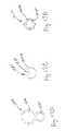
- FIG. 12Ais a cross-sectional side view of an infusion catheter according to one embodiment of the present invention.
- FIG. 12Bis a cross-sectional view of the infusion catheter taken along line A-A of FIG. 12A ;
- FIG. 12Cis a cross-sectional view of the infusion catheter taken along line B-B of FIG. 12A ;
- FIG. 12Dis a cross-sectional side view of an infusion catheter according to one embodiment of the present invention.
- FIG. 12Eis a cross-sectional view of the infusion catheter taken along line A-A of FIG. 12D ;
- FIG. 12Fis a cross-sectional view of the infusion catheter taken along line B-B of FIG. 12D ;
- FIG. 12Gis a cross-sectional side view of an alternative infusion catheter according to one embodiment of the present invention.
- FIG. 12His a cross-sectional view of the infusion catheter taken along line A-A of FIG. 12G ;
- FIG. 12Iis a cross-sectional side view of another infusion catheter according to one embodiment of the present invention.
- FIG. 12Jis a cross-sectional view of the infusion catheter taken along line A-A of FIG. 12I ;
- FIG. 12Kis a cross-sectional side view of an infusion catheter according to one embodiment of the present invention.
- FIG. 12Lis a cross-sectional view of the infusion catheter taken along line A-A of FIG. 12K ;
- FIG. 12Mis a cross-sectional side view of an infusion catheter according to one embodiment of the present invention.
- FIG. 12Nis a cross-sectional view of the infusion catheter taken along line A-A of FIG. 12M ;
- FIG. 13is a cross-sectional view of the partial length evacuation sheath of FIGS. 11A and 11B deployed in a blood vessel according to a further aspect of the present invention
- FIG. 14is a cross-sectional view of the partial length evacuation sheath of FIGS. 11A and 11B and the over the wire infusion sheath of FIGS. 12K and 12L deployed in a blood vessel according to a further aspect of the present invention
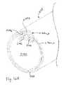
- FIG. 15is a cross-sectional view of a heart with a coronary sinus partially occluded by an occlusion catheter according to one aspect of the present invention.
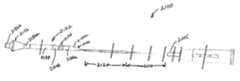
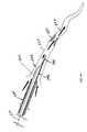
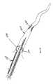
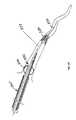
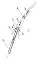
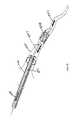
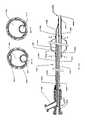
- FIG. 16Ais side view of a full-length evacuation sheath assembly according to another embodiment of the present invention.
- FIG. 16Bis a cross-sectional side view of the evacuation sheath assembly of FIG. 16A ;
- FIG. 16Cis an enlarged cross-sectional side view of a portion of the intermediate shaft portion of the evacuation sheath assembly in circle “C” of FIG. 16B ;
- FIG. 16Dis an enlarged cross-sectional side view of the proximal end of the evacuation sheath portion of the evacuation sheath assembly in circle “D” of FIG. 16B ;
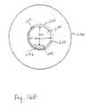
- FIG. 16Eis a cross-sectional view of the evacuation sheath assembly taken along line E-E of FIG. 16B ;
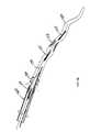
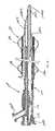
- FIG. 16Fis a cross-sectional side view of a distal end portion of the evacuation sheath portion of the evacuation sheath assembly of FIG. 16B ;
- FIG. 16Gis a cross-sectional side view of an alternative embodiment of a distal end portion of the evacuation sheath portion of the evacuation sheath assembly of FIG. 16B ;
- FIG. 16His an isometric sectional view of a marker portion and inflation lumen port of the evacuation sheath assembly of FIG. 16A ;
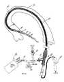
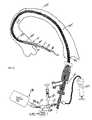
- FIG. 16Iis a side view of an arrangement with the evacuation sheath assembly of FIG. 16A in use with a guide catheter;
- FIG. 16Jis an isometric view of a support collar used in the evacuation sheath assembly of FIG. 16A ;
- FIG. 17Ais a cross-sectional side view of an infusion catheter according to another embodiment of the present invention.
- FIG. 17Bis a cross-sectional view of the infusion catheter taken along line B-B of FIG. 17A ;
- FIG. 17Cis a cross-sectional view of the infusion catheter taken along line C-C of FIG. 17A ;
- FIG. 17Dis a cross-sectional view of the infusion catheter taken along line D-D of FIG. 17A .
- the present inventionprovides a system and method for evacuating emboli, particulate matter, and other debris from a blood vessel, and particularly from an occluded blood vessel.
- an “occlusion,” “blockage,” or “stenosis”refers to both complete and partial blockages of the vessels, stenoses, emboli, thrombi, plaque, debris and any other particulate matter which at least partially occludes the lumen of the blood vessel.
- proximalrefers to the portion of the apparatus closest to the end which remains outside the patient's body
- distalrefers to the portion closest to the end inserted into the patient's body
- This method and apparatusare particularly suited to be used in diseased blood vessels that have particularly fragile lesions, or vessels whereby the consequences of even small numbers of small emboli may be clinically significant.
- blood vesselsinclude diseased SVGs, carotid arteries, coronary arteries with thrombus, and renal arteries.
- the method and apparatuscan be adapted to be used in other areas, such as other blood vessels.
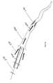
- an evacuation sheath assembly 100is provided.
- Evacuation sheath assembly 100includes an evacuation head and a shaft.
- the evacuation sheath assembly 100is sized to fit inside a guide catheter to advance a distal end of the evacuation sheath assembly into a blood vessel to treat a stenosis.
- evacuation sheath assembly 100may be suitable for use in other surgical procedures in other vessels, where reduction or removal of a blockage in a blood vessel is beneficial. Additionally, although the method of use of the evacuation sheath assembly will be described with respect to placing a stent within a vessel, the evacuation sheath assembly 100 can be used during other therapies, such as angioplasty, atherectomy, thrombectomy, drug delivery, radiation, and diagnostic procedures.
- an evacuation head 132is provided.
- Evacuation head 132includes a multi-lumen tube 138 .
- the multi-lumen tube 138is preferably made of a relatively flexible polymer such as low-density polyethylene, polyurethane, or low durometer Pebax® material.
- the multi-lumen tube 138can be made of a composite polymer and metal material or from other suitable biocompatible materials exhibiting appropriate flexibility, for example.
- the multi-lumen tube 138preferably includes first and second lumens. The first and preferably larger of the lumens, an evacuation lumen 140 , is designed to allow for the passage of interventional devices such as, but not limited to, stent delivery systems and angioplasty catheters.
- the evacuation lumen 140is also designed to allow for fluid flow, such as blood, blood/solid mixtures, radiographic dye and saline, within the evacuation lumen 140 . This flow of fluid may occur regardless of whether an interventional device is within the evacuation lumen 140 .
- the proximal and distal ends 140 a , 140 b of the evacuation lumen 140are preferably angled to allow for smoother passage of the evacuation sheath assembly 100 through a guide catheter, and into a blood vessel, and to facilitate smoother passage of other therapeutic devices through the evacuation lumen 140 of the evacuation head 132 .
- the larger area of the angled open endsalso allows for larger deformable particulate matter to pass through the lumen more smoothly.
- the second and preferably smaller lumen of the multi-lumen tube 138is an inflation lumen 142 (having an open proximal end 142 a and a closed distal end 142 b ) designed to provide fluid to inflate balloons on the evacuation head 132 .
- the fluidmay be either gas or liquid in form.
- FIG. 1CAn alternative construction of the multi-lumen tube 138 of the evacuation head 132 is shown in FIG. 1C .
- the multi-lumen tube 138may be formed around a coil 139 such that the coil 139 is embedded within the multi-lumen tube 138 .
- coil 139may be positioned on the inside surface defining the evacuation lumen 140 . The coil 139 can be “wound-down” initially, then re-expanded to make contact with the inner surface of evacuation lumen 140 .
- a covering of polyurethanecan then be applied to contain the coil 139 , and secure it in position within evacuation lumen 140 .
- the polyurethanemay be applied by a solvent casting of polyurethane in an appropriate solvent.
- the structuremay be formed by coextruding the shaft tube together with a coil or braid or by other suitable means.
- a further alternativemay include positioning the coil on the outer surface of the multi-lumen tube 138 .
- FIG. 11AAn alternative construction of the multi-lumen tube 138 of the evacuation head 132 is shown in FIG. 11A and incorporates a kink-resisting structure.
- a coil 139can be wound directly onto the multi-lumen tube or expanded from a wound state and slidingly placed over the multi-lumen tube. The proximal and distal ends of coil 139 are wound at a reduced pitch to allow the final coil to be positioned adjacent to the marker bands 146 a and 146 b . This produces a gradual stiffness transition to prevent kinking at the interface between the coil 139 and the marker bands 146 a and 146 b .
- a covering of polyurethane 133is then applied to contain the coil 139 , and secure it in position over the multi-lumen tube of evacuation head 132 .
- the polyurethanemay be applied by a solvent casting of polyurethane in an appropriate solvent.
- the structuremay be formed by applying a coating of UV curable polyurethane between multi-lumen/coil structure and a removable PTFE sleeve. The combination is then exposed to UV light and cured. The PTFE sleeve is then removed from the structure leaving a smooth coating surface 133 that encapsulates the coil 139 .
- the evacuation head 132also contains a flare 131 on the proximal end 140 a of the evacuation lumen 140 .
- This flare 131is intended to allow for easier passage of devices through the proximal end 140 a of the evacuation lumen 140 .
- the flare 131can also create a clearance seal that prevents the passage of fluid between the evacuation head 132 and the guide catheter 160 . This provides a sliding seal when the proximal and distal sealing balloons 134 and 136 are deflated.
- the evacuation lumen 140has a distal end 140 b that is angled.
- the angled distal endallows for the distal end 140 b to be more flexible than the portion of the evacuation head 132 that is proximal to it. This is intended to reduce the trauma induced into the vessel during delivery of the evacuation head 132 .
- the distance from the end of the balloon 136 and the distal end of the evacuation lumen 140 bis minimized to reduce a chance of the evacuation lumen distal end 140 b from coming in contact with the vessel wall while the distal sealing balloon 136 is inflated. This is intended to prevent the obstruction of flow through the evacuation lumen 140 .
- FIG. 11Bis a cross-sectional view of the assembly shown in FIG. 11A .
- FIG. 11Cis an alternative embodiment of an evacuation sheath assembly according to the present invention. This embodiment is similar to that described in connection with FIGS. 11A and 11B , except that the distal tip of the evacuation head 132 is cut perpendicular to the axis of the evacuation lumen 140 and proximate to the distal sealing balloon 136 . The perpendicular cut is useful when the anatomy is such that an angled distal end would contact the vessel wall in a way which limits fluid flow through evacuation lumen 140 .
- FIG. 11Dis a cross-sectional view of the assembly shown in FIG. 11C .
- the evacuation head 132includes at least one expandable sealing surface. As embodied herein and shown in FIG. 1A , two expandable sealing surfaces are provided.
- a first proximal sealing surfaceis configured to form a seal within the guide catheter which delivers the evacuation sheath assembly 100 to the surgical site, as will be described.
- First proximal sealing surfaceis preferably a proximal sealing balloon 134 .
- a second distal sealing surfaceis configured to form a seal within the blood vessel, as also will be described.
- Second distal sealing surfaceis preferably a distal sealing balloon 136 . As shown in FIG. 1A , it is preferable that the distal sealing balloon 136 be larger in size than the proximal sealing balloon 134 .
- the proximal balloon 134 and the distal balloon 136are in fluid communication with the inflation lumen 142 of evacuation head 132 .
- Inflation lumen 142is in fluid communication with a balloon inflation device 199 (see FIG. 5A ).
- the multi-lumen tube 138would comprise three lumens, two inflation lumens, each one in fluid communication with one of the sealing balloons 134 , 136 , and one evacuation lumen. Each lumen would be in fluid communication with its own lumen extending proximally to an inflation device (not shown).
- the proximal and distal balloons 134 , 136are formed of an elastomer such as polyurethane or silicone. It is preferable to utilize elastomeric balloons, particularly for the distal sealing balloon 136 , to allow the balloon to have a range of inflated diameters, depending on the volume of fluid infused into the balloon.
- Each sealing balloon 134 , 136includes two waist portions, one proximal 134 a , 136 a and one distal 134 b , 136 b of a body portion of the balloon.
- the waists portions 134 a , 134 b , 136 a , 136 bare preferably secured to an exterior of the multi-lumen tube 138 using heat welding, solvent bonding, or other suitable adhesive bonding techniques.
- proximal and distal sealing balloons 134 , 136are preferred, it is possible to instead use a single elastomeric tube extending nearly the full length of the multi-lumen tube 138 .
- the single elastomeric tubewould be secured to the outside of the multi-lumen tube 138 at the distal and proximal ends 140 b , 140 a of evacuation lumen 140 , as well as in the middle region of the evacuation lumen 140 .
- two expandable sealing surfacesare provided by the two regions of the single elastomeric tube which are not secured to the exterior of the shaft tube, i.e., the region between the proximal end 140 a and the middle region would form a proximal sealing surface, and the region between the distal end 140 b and the middle region would form a distal sealing surface.
- each balloon 134 , 136may be blow molded from tubing or dip molded to approximate the shape and minimum anticipated diameter of their final inflated condition. Particularly for the distal sealing balloon 136 , further inflation would further increase the diameter, as the balloon is preferably elastomeric. Alternatively, however, the balloons need not be pre-molded to the expanded shape. In such a variation, each balloon 134 , 136 is preferably a uniform diameter tube between the two balloon waists 134 a , 134 b , 136 a , 136 b . As the uniform diameter tubes are preferably elastomeric materials, they can be elastically expanded to the same shape and size as the alternative pre-molded balloons.
- each balloon 134 , 136it is preferable for the body portion of each balloon 134 , 136 to have a length at least as great as the maximum inflated diameter, and more preferably several times longer, for example about 3-4 times longer.
- proximal sealing balloon 134While it is preferred to provide the two expandable sealing surfaces of two elastomeric balloons 134 , 136 , as described above, it is possible to fabricate the proximal sealing balloon 134 of a non-elastomeric polymer molded to the shape and size as shown in FIG. 1A . Since the proximal balloon 134 is intended to be inflated within the guide catheter, it is only necessary for the proximal balloon 134 to be inflated against the internal diameter of the guide catheter.
- the distal sealing balloon 136preferably has a relatively wide range of expanded diameters, and therefore benefits from being elastomeric.
- the proximal sealing balloon 134will expand against the internal surface of the guide catheter, causing a seal, prior to any significant expansion of the distal sealing balloon 136 beyond its initial dimension.
- the evacuation sheath assembly 100is configured to be used with a guiding catheter 160 (see FIGS. 5A and 6A ).
- the guiding catheter 160performs an evacuation function in combination with the evacuation lumen 140 .
- the guiding catheter 160also maintains a contrast delivery function.
- the evacuation head 132with its two sealing balloons 134 , 136 inflated, is intended to isolate fluid communication of the internal lumen of the guide catheter 160 to the blood vessel 150 in which it is inserted.
- proximal and distal radiopaque markers 146 a , 146 bare placed at the site of each balloon 134 , 136 .
- two markersmay be placed proximally and distally adjacent to each balloon 134 , 136 .
- the proximal and distal radiopaque markers 146 a , 146 ballow the operator to radiographically position the two sealing balloons 134 , 136 in the proper location within the guiding catheter 160 and the blood vessel 150 .
- the distal balloon 136is intended to be positioned distal of the distal tip of a guiding catheter 160 and inflated against the inside surface of the blood vessel 150 causing a fluid tight seal between the blood vessel 150 and the balloon 136 .
- the proximal balloon 134is intended to be positioned proximal of the distal end of the guiding catheter 160 and inflated against the guiding catheter 160 causing a fluid tight seal.
- the preferred inflated diameters of the sealing balloons 134 , 136are thus determined by the intended application.
- a guiding catheter of 8 Frenchmay be utilized.
- the proximal sealing balloon 134will therefore require an inflated diameter capable of sealing against the inside of the guiding catheter, typically in the range of about 0.088-0.096 inches.
- the distal sealing balloon 136will need to be capable of sealing against the inside of the SVG, which typically has an inside diameter ranging from about 2.5-6 mm.
- the length of the evacuation head 132is dependent on the application for which the evacuation sheath assembly 100 is intended to be used. It is intended that the evacuation head 132 be long enough for the proximal sealing balloon 134 to be sealingly inflated within the guide catheter 160 , and the distal sealing balloon 136 to be sealingly inflated within the blood vessel of interest. In many applications, therefore, evacuation head 132 can be relatively short. For example, in the case of an SVG application, this length may be on the order of 2 to 5 cm. However, in a native coronary artery application, particularly in the left coronary circulation, it may be desired to have the evacuation head 132 longer, such that the distal sealing balloon 136 is positioned beyond the first or other main bifurcation. For example, it may be desired to position the distal sealing balloon 136 within the left anterior descending artery, distal of the left main artery. For this application, the evacuation head 132 is preferably about 5 to about 20 cm in length.
- the diameter of the evacuation head 132is also dependent on the intended application. As an example, preferred dimensions are described here with respect to an application in SVGs, with use of an 8 French guide catheter whose inner diameter is about 0.090 inches.
- the evacuation lumen 140may be approximately 0.061 inches, which will allow the passage of most therapeutic devices such as angioplasty catheters, stent delivery catheters, atherectomy catheters, drug delivery catheters, etc.
- the inflation lumen 142may have a dimension of about 0.005 inches at the widest portion of the crescent (vertical direction in FIG. 1B ).
- the wall thickness for most of the multi-lumen tube wall 138may be about 0.002 inches, and the balloon waist thickness may be approximately 0.002 inches.
- the evacuation sheath assembly 100includes a shaft.
- the shaftincludes a proximal shaft portion 110 , an intermediate shaft portion 120 , and a distal shaft portion 130 (not shown in FIG. 1A , shaft portion 130 includes evacuation head 132 ).
- Proximal shaft portion 110forms a hollow tube.
- proximal shaft portion 110is made of stainless steel, however, other structures and materials, such as polymer and metallic composites, (e.g., braid reinforced polymer tubes), nickel-titanium alloy, or other suitable materials exhibiting appropriate biocompatibility and flexibility properties may be used.
- the proximal shaft portion 110provides fluid communication between an inflation apparatus (not shown) and the intermediate and distal shaft portions 120 , 130 .
- the proximal shaft portion 110may also be coated with a polymer sleeve or spray coating for lubricity.
- the proximal shaft portion 110includes markers 115 on its exterior surface. These markers 115 are positioned to indicate to a user that the evacuation sheath assembly 100 has been advanced through the guiding catheter 160 to a location where the distal end of the evacuation sheath assembly 100 is just proximal to the distal end of the guiding catheter 160 .
- the proximal shaft portion 110is preferably secured to a luer hub 105 , for example by an overlapping weld or adhesive bond joint.
- the luer hub 105allows the evacuation sheath assembly 100 to be connected to an inflation apparatus for the inflation of the sealing balloons 134 , 136 . Any suitable inflation device may be used, including those resident in hospital cath labs.
- An intermediate shaft portion 120is secured to the proximal and distal shaft portions 110 , 130 , preferably by an overlapping weld or bond joint. Intermediate shaft portion 120 forms a hollow tube. Intermediate shaft portion 120 is preferably formed of polyethylene or Pebax, however, other polymers and polymer metallic composites, such as polyimide with an incorporated braid of stainless steel wire, or other suitable material exhibiting appropriate biocompatibility and flexibility characteristics, may be used.
- the intermediate shaft portion 120provides fluid communication between the proximal shaft portion 110 and the distal shaft portion 130 .
- the intermediate shaft portion 120also transmits longitudinal force from the proximal shaft portion 110 to the distal shaft portion 130 .
- the intermediate shaft portion 120is preferably more flexible than the proximal shaft portion 110 , to allow navigation of the curves within the distal region of the guiding catheter, as are often present, particularly in cardiac related applications.
- a distal end of the intermediate shaft portion 120is connected to a distal shaft portion 130 , preferably by welding or bonding.
- Distal shaft portion 130includes the inflation lumen 142 of multi-lumen tube 138 and a soft distal tip portion 144 .
- the inflation lumen 142is in fluid communication with the proximal shaft portion 110 and intermediate shaft portion 120 .
- the distal end of inflation lumen 142ends in a solid portion forming the distal end of the distal shaft portion 130 .
- the distal end of the distal shaft portion 130is tapered to form soft tip 144 .
- the soft tip 144may comprise a more flexible polymer secured to the distal end of the multi-lumen tube 138 of the evacuation head 132 .
- the soft tip 144may be fabricated of a low durometer polyurethane or Pebax.
- the soft tip 144allows the evacuation sheath assembly 100 to be placed atraumatically into the blood vessel, even if the blood vessel exhibits tortuosity.
- the shaft of the evacuation sheath assemblypreferably includes a stiffness transition member 135 .
- Stiffness transition member 135is attached to the distal end of the proximal shaft portion 110 , for example by welding or bonding.
- the stiffness transition member 135is preferably made of stainless steel, but other metals such as nickel titanium alloy or polymers may be used.
- the stiffness transition member 135is located co-axially in the inflation lumen 142 (as shown in FIG. 1B ) and extends from the proximal shaft portion 110 to the soft tip 144 .
- a distal end 137 of the stiffness transition member 135preferably includes a spring tip embedded into the material of the soft tip 144 . Embedding the spring tip into the soft tip 144 allows the stiffness transition member 135 to prevent longitudinal stretching or compressing of the evacuation sheath assembly 100 .
- the distal end 137 of the stiffness transition member 135can have a enlarged welded ball or other shape which can serve to mechanically interlock the stiffness transition member 135 within the soft tip 144 .
- the portion of the stiffness transition member 135 within the tip 144 of the evacuation sheath assembly 100also serves to allow the tip to be formed in a “J-bend”, similar to that for coronary guide wires.
- the stiffness transition member 135can then transfer rotational forces and motion imparted from the proximal region of the evacuation sheath assembly 100 to the tip 144 , to facilitate steering and navigation of the evacuation head 132 to a desired site in the blood vessel.
- the stiffness transition member's bending stiffnessdecreases gradually from the proximal end to the distal end of the stiffness transition member 135 . Preferably, this is accomplished by reducing the cross sectional area of the member 135 as shown in FIG. 1A , where stiffness transition member 135 includes three portions of decreasing diameter 135 a , 135 b , 135 c from proximal to distal end. However, this can also be accomplished by changes in shape and/or materials.
- the stiffness transition member 135allows for a gradual stiffness reduction in the evacuation sheath assembly 100 , which allows it to more smoothly navigate the curves of the guiding catheter and the blood vessel. This shaft construction is exemplary only, and is not intended to limit the invention.
- evacuation sheath assembly 100may be used in other surgical procedures and with other therapeutic devices, such as balloon angioplasty, atherectomy, thrombectomy, drug delivery, radiation, and diagnostic procedures.
- the lumen of a blood vessel 150is accessed with the distal end of a guiding catheter 160 , which is well known in the art and typical for coronary-type procedures.
- a coronary guide wire 170then is advanced to a location just proximal to the distal tip of the guiding catheter 160 . Blood flow at this point remains in the direction of normal arterial blood flow. The blood is flowing around and past the distal tip of the guiding catheter 160 and through the stenosis 180 as indicated by arrows 190 .
- the evacuation sheath assembly 100then is advanced over the guide wire 170 and positioned within the vessel 150 with the distal radiopaque marker 146 b distal of the distal tip of the guiding catheter 160 (i.e., within the vessel 150 ) and the proximal marker 146 a proximal of the distal tip of the guiding catheter 160 (i.e., within catheter 160 ), as determined through appropriate imaging techniques known in the art.
- the guide catheter 160may be positioned within the ostium of the target vessel, and the evacuation sheath assembly 100 may be advanced through the catheter and beyond a major side branch of the target vessel.
- Blood flowcontinues to be in the direction of normal arterial blood flow as shown by arrows 190 . Because the assembly 100 has as relatively short evacuation head 132 , the entire evacuation sheath assembly 100 can be advanced over a conventional length coronary guide wire 170 after the guide wire 170 has been placed within the guide catheter 160 .
- the distal and proximal sealing balloons 136 , 134are inflated as shown in FIG. 6C .
- the distal sealing balloon 136provides a fluid tight seal between the sealing balloon 136 and the blood vessel 150 and the proximal sealing balloon 134 provides a fluid tight seal between the sealing balloon 134 and the interior diameter of the guiding catheter 160 .
- a suitable valve 184such as a touhy borst valve, attached to the guiding catheter 160 (shown in FIG. 5A ) provides a fluid tight seal against the guide wire 170 and the proximal shaft portion 110 of the evacuation sheath assembly 100 .
- the three fluid tight sealsestablish fluid communication between the distal end of the evacuation sheath assembly 100 and a fluid collection chamber, filter, and vacuum source 188 , which is attached to the Y-adaptor (conventional) 184 shown in FIG. 5A .
- a blood pressure transducer 192is commonly connected in fluid communication with the lumen of the guide catheter 160 (through additional stop cocks or manifolds as is well-known in the art) to monitor arterial blood pressure.
- the blood pressure waveformcan be observed to change from a relatively high pressure and pulsatile waveform of the artery, to a relatively low and constant waveform of the venous pressure. This pressure observation is an important indicator that the sealing balloons 134 , 136 have effectively isolated fluid communication to the coronary artery. With the three fluid tight seals in place, a normal antegrade flow within the artery is stopped. Thus, there is substantially no blood flow within the vessel 150 , as indicated by the lack of arrows in FIG. 6C .
- the evacuation lumen 140 of the evacuation head 132becomes an extension of the guide catheter lumen for this contrast delivery. Because normal antegrade blood flow in the coronary artery has been effectively stopped, the contrast will remain in the coronary artery, rather than quickly washing away. This may be advantageous for the subsequent navigation of the guide wire 170 .
- the guide wire 170is advanced across the stenosis 180 .
- the touhy borst valve 184 on the Y-adaptorshown in FIG. 5A
- the wiremay be desirable to cause retrograde flow in the coronary artery ( FIG. 6D ), as the act of crossing a stenosis 180 with a wire 170 (particularly a fragile lesion (stenosis), such as in an SVG) may in itself dislodge material. Any material dislodged will not travel downstream, as the antegrade flow has already been stopped. Retrograde flow can be used to remove the dislodged material.
- Retrograde flowis represented in FIG. 6D by arrows 195 .
- This retrograde flowis due to the venous pressure head, and will begin once the pressure in the collection bottle 188 is vented to atmospheric pressure. Flow can also be increased by applying vacuum to the collection chamber and filter 188 . This retrograde flow will carry any dislodged material out of the patient and into a collection chamber.
- the collection chambermay be a simple syringe or may be any other suitable container. If a syringe is used, withdrawal of the plunger automatically causes a vacuum to induce retrograde flow.
- the flowcan be stopped by closing the valve to atmosphere pressure or by releasing the vacuum. If desired, after any dislodged material has been removed, the balloons 134 , 136 of the evacuation sheath assembly 100 may be temporarily deflated, allowing for a period of antegrade blood flow and perfusion of the vessel 150 .
- a therapeutic devicesuch as a stent delivery system 193 is advanced across the stenosis 180 with antegrade flow stopped, as shown in FIG. 6E .
- the touhy borst valve 184 attached to the guide catheter 160which is shown in FIG. 5A , seals against the proximal end of the therapeutic device, the guide wire 170 and the proximal shaft portion 110 of the evacuation sheath assembly 100 .
- advancement of the delivery systemmay be done with retrograde flow.
- some contrastmay be delivered into the vessel, allowing continuous visualization of the vessel and stenosis for more precise placement of the stent delivery catheter 193 .
- the touhy borst valve 184 through which the stent delivery catheter 193 passesmust be opened just enough to allow for advancement of the device with little to no backbleeding.
- a stent delivery balloonis inflated to expand a stent 194 against the vessel wall, opening a passage for blood flow through the stenosis 180 ( FIG. 6F ).
- retrograde flowif present is discontinued by the occlusion of the blood vessel by the therapeutic device and the stoppage of any applied vacuum.
- the stent delivery balloonis deflated and retrograde flow is re-established in the vessel 150 .
- Any embolic material 197 dislodged from the therapeutic siteis carried back to the evacuation lumen 140 of the evacuation head 132 by the retrograde flow 195 ( FIG. 6G ).
- the embolic material 197may include material dislodged during advancement of the therapeutic device, or during the expansion of the stent 194 , in the case where the therapeutic device includes a stent 194 .
- the retrograde flow 195is re-established when the therapeutic device is no longer occluding the blood flow, and additional vacuum is preferably applied to the evacuation lumen 140 .
- the therapeutic devicemay be left in place while there is retrograde flow, or it may be positioned proximal to the stenosis 180 , or even brought back within the lumen of the guide catheter 160 .
- additional contrast delivery to the blood vesselmay indicate a need for more therapeutic steps, e.g., further dilation of the stent with the balloon. In this case, it is more convenient to have the balloon catheter already in position for any subsequent use.
- the therapeutic deviceis removed from the vessel 150 (retrograde flow may or may not be maintained) ( FIG. 6H ).
- the distal and proximal sealing balloons 136 , 134are then deflated ( FIG. 6I ), establishing normal arterial flow.
- the diameter of an evacuation headmay be expandable from a first introduction diameter to a second operational diameter.
- an evacuation sheath assembly 200is provided with an expandable evacuation head 232 .
- Many of the elements present in the previous embodimentare also shown in FIGS. 2A-2D and where these elements are substantially the same, similar reference numerals have been used and no detailed description of the element has been provided.
- the evacuation head 232preferably includes an inner layer 226 that will serve as an evacuation lumen and an outer layer 228 that will serve as the sealing surfaces.
- the inner layer 226is fabricated from polyethylene PET or Pebax, but other suitable materials may be used.
- the evacuation head 232has a proximal end 232 a and a distal end 232 b .
- FIGS. 2A and 2Bshow the evacuation head 232 in an unexpanded state and FIGS. 2C , 2 D, and 2 E show the evacuation head 232 in an expanded state.
- the inner layer 226 of the evacuation head 232preferably comprises a tube that unfolds to increase in diameter. In FIG. 2C , the increase in diameter assumes a step-wise shape.
- a distal portion of the inner layer 226 of the evacuation headhas an expanded diameter which is larger than a diameter of a guide catheter 260 .
- the expanded shape of the inner layer 226 of the expandable evacuation head 232may include a proximal portion having a first diameter and a distal portion having a second diameter, the second diameter being larger than the first such that the inner layer 226 of the evacuation head 232 has a larger dimension in the region which resides within the blood vessel, as shown in FIG. 2C .
- the diameters of the proximal and distal portions of the inner layer 226 of the evacuation head 232may be the same, such that the diameter of an expanded inner layer 226 is the same for the region outside of the guide catheter as the region which resides within the guide catheter.
- the distal and proximal ends of the expanded evacuation head 232may be angled relative to its longitudinal axis, as discussed with respect to the embodiment shown in FIG. 1A , although this is not shown in FIGS. 2A-2D .
- the low profile folded delivery state of the evacuation head 232may not require such angles.
- the entire open distal end of the expandable evacuation head 232is suitable for positioning close to the desired therapy site.
- the outer layer 228 of evacuation headincludes multiple spherical balloons (or balloon regions) 233 , including a proximal most balloon 234 and a distal most balloon 236 , with a cylindrical waist between each balloon.
- the inner and outer layers 226 , 228 of the evacuation head 232may be seam welded or bonded together around the circumference at each waist location, while the inner layer 226 is in its expanded condition.
- the evacuation head 232Prior to insertion of the evacuation sheath assembly 200 into the guide catheter 260 , the evacuation head 232 is folded into its unexpanded condition, as shown in FIGS. 2A and 2B .
- fluideither a gas or liquid
- the outer layer 228expands radially.
- the outer layer 228expands into multiple balloon regions 233 , it pulls the inner layer 226 with it, opening the evacuation lumen 240 .
- the inner and outer layersexpand together in the radial direction when inflated.
- the evacuation head 232comprises a multi-lumen tube 238 having an evacuation lumen 240 and an inflation lumen 242 .
- the inflation lumen 242is in fluid communication with intermediate and proximal shaft portions 210 , 220 and is in fluid communication with the individual balloon segments 233 , 234 , 236 , such that when fluid is infused into inflation lumen 242 , the evacuation head 232 expands. Further infusion of fluid into the inflation lumen of the evacuation sheath assembly will inflate the distal and proximal sealing balloons until they are appropriately sized to cause effective sealing.
- the evacuation head 232includes a proximal sealing balloon 234 and a distal sealing balloon 236 .
- the proximal sealing balloonis configured to seal with an inner diameter of the guide catheter 260 and the distal sealing balloon is configured to seal with the inner walls of blood vessel 250 .
- the remaining balloons 233need only be sized to an inflated diameter sufficient to “pull” open the inner layer 226 of the expandable evacuation head 232 .
- three intermediate balloons 233are shown in FIG. 2C , more or fewer balloons may be provided as appropriate, for example depending upon the length of the evacuation head to be expanded.
- intermediate balloons 233are intended to “pull” open evacuation lumen 240 of the evacuation head 232
- balloons 233may also provide addition sealing under certain circumstances, as shown in FIG. 2C . However, it is less important that the remaining balloons 233 be elastomeric, as they do not necessarily require a range of expanded diameters.
- the evacuation head 232is folded into a reduced diameter configuration. As illustrated, this folding may be in a generally “w” type fold, however other folding configurations are contemplated, such as “s” folds or “c” folds. It is also preferable to heat set the folded evacuation head 232 in this configuration. Because the evacuation head has been heat set in a folded configuration, once the sealing balloons and remaining balloons are deflated after a procedure, the evacuation head will refold toward its pre-expanded configuration.
- the low profile of the evacuation head 232 in its delivery configuration and the soft tip 244 at the end of evacuation sheath assembly 200allow the expandable evacuation sheath assembly 200 to be passed through smaller and more tortuous lumens and blood vessels.
- the expandable evacuation lumen 240also allows the evacuation sheath assembly 200 to be sized more closely to the guiding catheter 260 and larger than the guiding catheter 260 in the portion that is placed distal of the guiding catheter when it is in the expanded state. This larger lumen allows for high evacuation flow rates, and eases the ability for large particles to be removed from the blood vessel during or subsequent to the therapeutic procedure, while having a relatively small collapsed delivery condition.
- evacuation sheath assembly 200is deployed in a similar manner as discussed with respect to evacuation sheath assembly 100 .
- the steps for using evacuation sheath assembly 200 with a guide catheter 260 in a vessel 250are sequentially depicted in FIGS. 7A-7I .
- evacuation sheath assembly 200As shown in FIG. 7A , guide catheter 260 and guide wire 270 are advanced proximate to a blood vessel 250 . Subsequently, evacuation sheath assembly 200 , with evacuation lumen 240 in its delivery configuration, is advanced over the guidewire 270 into guide catheter 260 and blood vessel 250 ( FIG. 7B ). Once evacuation head 232 is properly positioned, as can be verified using proximal markers 115 and markers 246 a , 246 b , evacuation head 232 is expanded ( FIG. 7C ) until evacuation lumen 240 is open. Fluid continues to be injected into the balloons until proximal balloon 234 creates a seal with the lumen of guide catheter 260 and until distal balloon 236 creates a seal with blood vessel 250 .
- the stenosis 280is treated and any embolic debris 297 is removed via retrograde flow 295 ( FIGS. 7C-7H ), as previously described with respect to FIGS. 6C-6H .
- evacuation head 232including proximal and distal sealing balloons 234 , 236 , is deflated and then removed from blood vessel 250 ( FIG. 7I ).
- the evacuation headmay comprise an elongated multi-lumen tube.
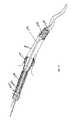
- an evacuation sheath assembly 300is provided with an evacuation head 332 .
- Many of the elements present in the previous embodimentsare also shown in FIGS. 3A and 3B and where these elements are substantially the same, similar reference numerals have been used and no detailed description of the element has been provided.
- evacuation head 332includes a single elongated multi-lumen tube 338 .
- the size of the tube 338allows it to be placed through a guiding catheter 360 and into a blood vessel 370 (see FIG. 5C ).
- the tubemay be made from a polymer such as polyethylene or Pebax® material or materials described with respect to FIG. 1A .
- the tube 338may include a coil or braid, as in FIG. 1C , in all or only portions of the tube.
- the multi-lumen tube 338includes two lumens 340 , 342 .
- the larger of the lumens, the evacuation lumen 340is designed to allow for the passage of interventional devices such as, but not limited to stent delivery systems and angioplasty catheters.
- the lumenis also designed to allow for fluid flow, such as blood, blood/solid mixtures, radiographic dye and saline, within the lumen as discussed with respect to FIGS. 1A-1C .
- a distal end of the tube 338is tapered into a soft tip 344 , as described in connection with previous embodiments.
- the soft tip 344allows the evacuation sheath assembly 300 to be placed more smoothly into the blood vessel.
- the tube 338includes inflation lumen 342 , which allows for fluid communication between the proximal end of the evacuation sheath assembly 300 and an expandable sealing surface.
- the elongated multi-lumen tube 338defines the entire evacuation lumen 340 , unlike the devices shown in FIGS. 1A-2D which make use of a significant length of the lumen of the guide catheter for evacuation. For this reason, only a single expandable sealing surface is required.
- the expandable sealing surfaceis preferably a distal sealing balloon 336 .
- Distal sealing balloon 336may comprise an elastomeric material such as polyurethane or silicone.
- the distal sealing balloon 336is configured be positioned distal of the distal tip of a guiding catheter 360 and inflated against the blood vessel 350 causing a fluid tight seal between the blood vessel 350 and the balloon 336 .
- Radiopaque marker 346is preferably placed at the site of the sealing balloon 336 . The radiopaque marker 346 allows the operator to radiographically position the sealing balloon 336 in the proper location within the blood vessel 350 .
- a proximal shaft portion 310 of the evacuation sheath assembly 300is sealed against a valve 384 , such as a touhy borst valve, on the guide catheter 360 creating a fluid tight seal against the evacuation sheath assembly 300 and the guiding catheter 360 .
- a valve 384such as a touhy borst valve
- the tube 338includes proximal markers 315 placed on the exterior of the proximal portion of the tube 338 . These markers 315 are positioned to indicate that the tube 338 has been advanced through the guiding catheter 360 to a location where the distal end of the evacuation sheath assembly 300 is just proximal to the distal end of the guiding catheter 360 .
- a proximal portion of the tube 338is secured to a bifurcated luer hub 305 by an overlapping weld or bond joint.
- the bifurcated luer hub 305includes an inflation port 302 and a vacuum port 303 which allows the evacuation sheath assembly 300 to be connected to an inflation apparatus and a vacuum source, respectively.
- the evacuation sheath assembly 300is deployed in a similar manner to that discussed with respect to evacuation sheath assembly 100 .
- the steps of using evacuation sheath assembly 300 with a guide catheter 360 in a vessel 350are sequentially depicted in FIGS. 8A-8I .
- the differences between the method discussed with respect to evacuation sheath assembly 100 and that for evacuation sheath assembly 300are discussed below.
- evacuation sheath assembly 300runs the full length of evacuation sheath assembly 300 , the evacuation sheath assembly 300 should be inserted together with the coronary guide wire 370 . Also, because the lumen of the guide catheter 360 is more fully obstructed by this evacuation sheath assembly 300 , it is preferable to inject contrast directly into the proximal end of the evacuation lumen 340 of the evacuation sheath assembly 300 (or into both lumen 340 and the lumen of guide catheter 360 ), rather than just into the lumen of the catheter 360 .
- both the guide catheter lumen and the evacuation lumen 340can be used for pressure monitoring, although it is more desirable to use the evacuation lumen 340 for pressure monitoring to confirm a tight seal between the distal balloon 336 and blood vessel 350 as needed.
- only one sealing balloon 336is used to provide the seal in the evacuation sheath assembly 300 , as shown in FIGS. 8C-8H .
- guide catheter 360is positioned within blood vessel 350 .
- evacuation sheath assembly 300is advanced with guidewire 370 into blood vessel 350 ( FIG. 8B ).
- distal marker 346Proper positioning of a distal end of evacuation sheath assembly 300 may be confirmed using distal marker 346 .
- distal sealing balloon 336is inflated via inflation port 302 , stopping blood flow within blood vessel 350 .
- contrast dyemay be injected through evacuation lumen 340 into blood vessel 350 to view blood vessel 350 prior to treating stenosis 380 .
- Stenosis 380is then treated and any embolic debris 397 is removed via retrograde flow 395 through evacuation lumen 340 ( FIGS. 8C-8H ), as previously described with respect to FIGS. 6C-6H .
- distal sealing balloon 336is deflated and evacuation sheath assembly 300 is removed from blood vessel 350 ( FIG. 8I ).
- the evacuation sheath assemblymay comprise an elongated multi-lumen tube which eliminates the need for a separate guiding catheter.
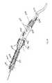
- an evacuation/guiding sheath assembly 400is provided with an evacuation/guiding lumen 440 .
- Many of the elements present in the previous embodimentsare also shown in FIGS. 4A and 4B and where these elements are substantially the same, similar reference numerals have been used and no detailed description of the element has been provided.
- evacuation/guiding sheath assembly 400includes a single elongated multi-lumen tube 438 .
- the size of the tube 438allows it to be used as a combination guiding catheter and evacuation lumen, to deliver interventional devices into a blood vessel 450 .
- the multi-lumen tube 438is preferably formed of a Pebax®, stainless steel and PTFE composite material, very similar to conventional guide catheters, well known in the art, with the exception that an additional lumen in the wall of the tube is provided.
- Tube 438can be made of other suitable polymers and metal materials.
- the multi-lumen tube 438includes first and second lumens.
- the larger of the lumens, the evacuation/guiding lumen 440is designed to allow for the passage of interventional devices such as, but not limited to, stent delivery systems and angioplasty catheters.
- the lumen 440is also designed to allow for fluid flow, such as blood, blood/solid mixtures, radiographic dye and saline, within the lumen. This flow of fluid is allowed with or without an interventional device in the evacuation/guiding lumen 440 .
- the tube 438can be pre-formed in various curvatures during manufacturing to allow for easy access to the ostium of several different blood vessels in a manner similar to conventional guide catheters as known in the art. Note that FIGS. 4A and 4B do not show these pre-formed curves.
- the distal end of the tube 438is preferably fitted with a more flexible material, forming a soft distal tip 444 . This flexible tip 444 allows the evacuation/guiding lumen 440 to be placed more smoothly into the blood vessel.
- the tube 438also contains an inflation lumen 442 , which allows for fluid communication between a proximal end of the evacuation/guiding sheath assembly 400 and an expandable sealing surface on a distal end of the evacuation/guiding sheath assembly 400 .
- the expandable sealing surfaceis an inflatable sealing balloon 436 .
- the sealing balloon 436is preferably elastomeric and may comprise polyurethane or silicone, similar to that of the distal sealing balloon of FIGS. 1A-1C .
- the sealing balloon 436is intended to be positioned distal of the ostium of the blood vessel 450 and inflated against the blood vessel 450 causing a fluid tight seal between the blood vessel 450 and the balloon 436 .
- Radiopaque markers 446are preferably placed at the site of the sealing balloon 436 to allow radiographically verifying the position of the sealing balloon 436 .
- the proximal portion of the tube 438is sealed against a interventional device by a bifurcated touhy borst valve 484 attached to the evacuation/guiding sheath assembly 400 to create a fluid tight seal against the evacuation/guiding sheath assembly 400 and the interventional device.
- a proximal portion of the tube 338is secured to the bifurcated touhy borst luer hub 484 by an overlapping weld or bond joint.
- the bifurcated luer huballows the evacuation sheath assembly to be connected to an inflation apparatus and a vacuum source through an inflation port 402 and a vacuum port 403 , respectively.
- FIGS. 9A to 9HThe steps of using evacuation/guiding sheath assembly 400 are sequentially depicted in simplified FIGS. 9A to 9H .
- Use of evacuation/guiding sheath assembly 400is similar to the method described with respect to evacuation sheath assembly 100 .
- the differences between the method discussed with respect to FIGS. 6A-6I and that for evacuation/guiding sheath assembly 400are discussed below.
- the lumen of the blood vessel 450is accessed with the distal tip 444 of the evacuation/guiding sheath assembly 400 .
- a guide wire 470is advanced to a location just proximal to the distal tip 444 of the evacuation/guiding sheath assembly 400 ( FIG. 9A ). Blood flow at this point remains in the direction of normal arterial blood flow as shown by arrows 490 .
- the evacuation/guiding sheath assembly 400is then positioned with the distal marker band 446 distal of the ostium of the blood vessel 450 . Once the positioning of the distal tip 444 of the evacuation/guiding sheath assembly 400 is verified, the distal sealing balloon 436 is inflated as shown in FIG. 9B to stop normal antegrade flow.
- the distal sealing balloon 436provides a fluid tight seal between the sealing balloon 436 and the blood vessel 450 .
- the distal sealing balloon 436may be shaped such that it seals against the aortal surface and the most adjacent portion of the coronary ostium (not shown).
- a touhy borst valve 484 attached to the evacuation/guiding sheath assembly 400provides a fluid tight seal around the guide wire 470 .
- the two fluid tight sealsestablish fluid communication between the distal end of the evacuation/guiding sheath assembly 400 and a fluid collection chamber, filter, and vacuum source 488 , which is attached to the bifurcation lumen of the touhy borst valve 484 shown in FIG. 5D , and stop normal antegrade blood flow within blood vessel 450 .
- a blood pressure transducer 492is commonly connected in fluid communication with the lumen of the guide catheter to monitor arterial blood pressure.
- contrast dyemay be injected through evacuation/guiding lumen 440 into blood vessel 450 prior to treating stenosis 480 .
- Stenosis 480is then treated and any embolic debris 497 is removed via retrograde flow 495 through evacuation/guiding lumen 440 ( FIGS. 9C-9G ) as previously described with respect to FIGS. 6C-6H .
- distal sealing balloon 436is deflated and evacuation/guiding sheath assembly 400 is removed from blood vessel 450 ( FIG. 9H ).
- the diameter of an evacuation headmay be expandable from a first introduction diameter to a second operational diameter.
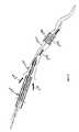
- an evacuation sheath assembly 500is provided with an expandable evacuation head 532 .
- Many of the elements present in the previous embodimentare also shown in FIGS. 10A-10D and where these elements are substantially the same, similar reference numerals have been used and no detailed description of the element has been provided.
- the evacuation head 532 of the present embodimentis similar to the first and second embodiments previously discussed in that the evacuation sheath assembly 500 comprises a relatively short evacuation head 532 .
- Evacuation sheath assembly 500also makes use of the guide catheter 560 to form a part of an evacuation lumen 540 .
- evacuation head 532includes a tube 538 having a single expandable lumen, evacuation lumen 540 .
- Evacuation head 532may have a naturally unexpanded state. Alternatively, evacuation head 532 may be designed to normally be in an expanded state. However, it is preferred to have the evacuation head 532 fabricated to have its natural shape and size in the reduced dimension, as shown in FIG. 10B .
- the evacuation head 532includes two sealing surfaces 534 , 536 .
- a proximal sealing surface 534is intended to seal against an inside distal portion of the guide catheter 560 and a distal sealing surface is intended to seal against the inside of the blood vessel 550 , for example a coronary artery or an SVG.
- the expandable evacuation head 532could include two balloon-type seals, for example by adding a sealing balloon to each end of a tube 538 forming evacuation head 532 , it is preferable to simply allow the outer surface of the expandable evacuation head 532 to create the sealing surfaces 534 , 536 .
- evacuation tube 538is formed of a braided sheath and a coating or covering over the braided sheath.
- the braided sheathitself can be made of stainless steel (full hard or spring), EligiloyTM, nickel titanium alloy or other metals or polymers with high elasticity characteristics.
- the braided sheath which forms tube 538has a length of between about 3 cm and about 20 cm.
- the braided sheathcan be coated with a polymer such as polyurethane, silicone and other similar elastomeric materials that can stretch and allow the braided sheath to expand.
- the covering or coatingis preferably a thin and flexible elastomer, which is dip coated on the braided sheath. Since the elastomeric covering or coating is applied to the braided sheath in its reduced dimension, the covering or coating helps to retain the braided sheath in its reduced dimension.
- the braided sheathcan be fitted with a fluid tight woven material that has similar expansion qualities as the braided sheath.
- the coveringis a braided fabric, it is preferably made from polyester or other high strength polymer yarn.
- the coveringmay be formed of a spun fibers laid down in multiple layers back and forth along the length of the braided sheath. If the fiber layers are laid down at the same helical angle as the primary braided sheath, the covering will behave similarly to the primary braided sheath upon expansion, requiring little or no expansile force to expand the covering from its reduced dimension to its expanded dimension.
- Each fiber layerwill be made of several adjacent fiber windings to create a dense layer.
- there are multiple layers, which togetherwill be relatively impervious to fluid flow, thereby allowing sealing surfaces of the evacuation head 532 to effectively isolate fluid communication from the lumen of the guide catheter with the lumen of the blood vessel.
- the braided sheathis preferably fabricated at its desired reduced diameter, for example, as utilized in an SVG with an 8 French guide catheter, about 0.4-1.5 mm.
- the braided sheathis then coated or covered at this reduced size.
- the braided sheath which comprises the evacuation head 532is preferably connected to an actuation wire 513 by a few of the filaments near the distal end of the braided sheath.
- a proximal hollow shaft 511is connected to a few of the braid filaments near a proximal end of the evacuation head 532 and serves as an anchor point.
- Actuation wire 513sits within the hollow shaft 511 and the braided sheath is preferably bonded or welded to the proximal hollow shaft 511 at the proximal end of the braided sheath and to the actuation wire 513 on the distal end of the braided sheath.
- the bondsattach in a manner that does not considerably impede the free movement of the braided sheath during expansion and contraction.
- the proximal hollow shaft 511is a tube, which preferably decreases in stiffness from a proximal end to a distal end thereof.
- the proximal hollow shaft 511can be made of stainless steel hypotubing, polyethylene, or a composite of polymers and metal.
- the evacuation head 532includes a steerable spring tip 544 extending from the actuation wire 513 .
- a nose cone 543Surrounding a portion of the spring tip 544 is a nose cone 543 .
- the nose cone 543serves as a tapering transition between the spring tip 544 and a distal end of a delivery sheath 547 .
- the nose cone 543facilitates smooth advancement of the evacuation sheath assembly through a guide catheter 560 and into the blood vessel 550 .
- the delivery sheath 547preferably comprises a tube which covers the entire length of the reduced dimension of the evacuation head 532 .
- the delivery sheath 547is connected to a wire shaft (not shown), which emerges from a proximal end of the guide catheter 560 .
- the delivery sheath 547may be fully removed from the lumen of the guide catheter 560 , or can be left in position within the guide catheter 560 .
- the delivery sheath 547may include a perforated longitudinal line to allow for splitting of the delivery sheath 547 and removal of the delivery sheath 547 from the proximal hollow shaft 511 of the evacuation sheath assembly 500 .
- the delivery sheath 547would preferably be usable during contracting and removal of the braided sheath.
- the delivery sheath 547could be re-advanced to cover and constrain the braided sheath once the procedure is completed. In this manner, the evacuation sheath assembly 500 could be removed from the guide catheter 560 .
- the proximal end of the evacuation sheath assembly 500may have an adjustable lock to anchor the actuation wire 513 to the proximal hollow shaft 511 , allowing them to be held fixed to one another. This allows the braided sheath to be locked into a set position.
- the evacuation sheath assembly 500in use, is depicted in FIG. 10D .
- Use of evacuation sheath assembly 500is similar to the method described with respect to evacuation sheath assembly 100 .
- the differences between the method discussed with respect to FIGS. 6A-6I (evacuation sheath assembly 100 ) and that for evacuation sheath assembly 500are discussed below.
- a guide catheter 560is advanced into blood vessel lumen 550 over a guidewire 570 .
- Evacuation sheath assembly 500in a compressed state having a reduced diameter and enclosed in delivery sheath 547 , is advanced through the lumen of guide catheter 560 over guidewire 570 and part way into blood vessel 550 .
- Proper positioning of a distal end of evacuation sheath assembly 500is confirmed using, for example, marker 545 , nose cone 543 , or by viewing the braided sheath through imaging.
- the delivery sheath 547is removed from the evacuation head 532 .
- the actuation wire 513is then pulled proximally while the proximal hollow shaft 511 is held stationary, preferably by a valve. Pulling the actuation wire 513 proximally longitudinally compresses the braided sheath forming evacuation lumen 540 , causing it to expand in diameter.
- the evacuation lumen 540expands and the proximal sealing surface 534 of the evacuation head 532 seals against the inside surface of the guide catheter 560 .
- the portion of the evacuation lumen 540 extending beyond the guide catheter 560 and into the blood vessel 550continues to expand until the distal sealing surface 536 of the evacuation head 532 seals against the inside surface of the blood vessel 550 . Similar to previous embodiments, the expansion can be observed with fluoroscopy, and the blood pressure can be monitored 592 until the waveform changes from pulsatile arterial pressure to a venous pressure (again, in the example of a coronary or SVG blood vessel).
- contrast dyemay be injected through the catheter lumen into blood vessel 550 to view blood vessel 550 prior to treating stenosis 580 .
- Stenosis 580is then treated and any embolic debris is removed via retrograde flow 590 ( FIG. 10D ) as previously described with respect to FIGS. 6C-6H .
- the actuation wire 513is re-advanced to allow the braided sheath to contract and be maintained in its reduced dimension prior to withdrawing the evacuation sheath assembly 500 from blood vessel 550 .
- the multi-lumen tube forming the evacuation headmay include three lumens.
- an evacuation sheath assembly 2100is provided with an evacuation head 2132 .
- Many of the elements present in the previous embodimentsare also shown in FIGS. 16A-16J and where these elements are substantially the same, similar reference numerals have been used and no detailed description of the element has been provided.
- an evacuation sheath assembly 2100is provided with and includes an evacuation head and a shaft.
- the evacuation headincludes two expandable sealing surfaces on a multi-lumen tube.
- the evacuation sheath assemblyis sized to fit within and to be used with a guide catheter during the treatment of a vascular stenosis, e.g. within a coronary artery, such as a native coronary artery or an SVG.
- the evacuation headmay be between about 3 and 40 cm in length, and is preferably between about 10 and 20 cm in length. In a most preferred embodiment, the evacuation head is about 15 cm in length.
- the total length of the evacuation sheath assembly 2100 for coronary applications, not including any luer fittingsis preferably between about 110 cm and about 200 cm, and most preferably about 135 cm in length.
- the evacuation head 2132includes a multi-lumen tube 2138 .
- Multi-lumen tube 2138is preferably made of a relatively flexible polymer, for example, a polyester blend such as Hytrel 6356.
- Hytrel 6356has a relatively high melt temperature to facilitate subsequent heat bonding, as well as a relatively high lubricity and a relatively high flexibility.
- the multi-lumen tube 2138preferably includes three lumens and has a circular cross-section.
- the outer diameter of the multi-lumen tubeis dependent upon the size of the guide catheters with which the evacuation sheath assembly 2100 is intended to be used.
- a presently preferred guide catheteris a size 8 French, a size readily available from many manufacturers.
- the multi-lumen tube 2138preferably has an outer diameter of between 0.065 and 0.080 inches, with an outer diameter of 0.072 inches being most preferred.
- Accommodation within a size 8 French guide catheterrequires the multi-lumen tube 2138 to have an inner diameter ID 1 of between 0.060 and 0.075 inches, and most preferably 0.067 inches (see FIG. 16E ). This results in a wall thickness of approximately 0.0025 inches for the multi-lumen tube 2138 , which varies dependent upon the inner and outer diameters of the multi-lumen tube 2138 .
- an evacuation lumen 2140is designed to allow for the passage of interventional devices such as, but not limited to, stent delivery systems and angioplasty catheters.
- FIGS. 16E-16Gmost clearly show evacuation lumen 2140 .
- the evacuation lumen 2140is also designed to allow for fluid flow, such as blood, blood/solid mixtures, radiographic dye and saline, within the evacuation lumen 2140 . This flow of fluid may occur regardless of whether an interventional device is within the evacuation lumen 2140 .
- the proximal end 2140 a of the evacuation lumen 2140is preferably angled to facilitate smooth passage of other therapeutic devices through the evacuation lumen 2140 of the evacuation head 2132 .
- a second and preferably smaller lumen of the multi-lumen tube 2138is an inflation lumen 2142 having an open proximal end 2142 a and a closed distal end 2142 b .
- FIGS. 16E-16Gmost clearly show inflation lumen 2142 .
- the distal end 2142 b of the inflation lumen 2142is preferably closed with an adhesive, although other suitable materials, for example, thermal bonding, may be used to close the end 2142 b of the lumen 2142 .
- the inflation lumen 2142is designed to provide fluid to inflate balloons on the evacuation head 2132 .
- the fluidmay be either gas or liquid in form, and is preferably a mixture of radiopaque contrast media and saline.
- the third lumen of the multi-lumen tube 2138is also preferably smaller than the evacuation lumen 2140 and forms a core wire lumen 2143 , as most clearly shown in FIG. 16E .
- a core wire 2135preferably extends only a portion of the length of the multi-lumen tube 2138 , and is therefore not present within the core wire lumen 2143 of the distal portion of the multi-lumen tube 2138 .
- the distal end of the core wire lumen 2143is preferably closed with an adhesive, although other suitable means such as thermal bonding may be used.
- the inflation lumen 2142 and the core wire lumen 2143are preferably positioned side-by-side against the inner wall of the multi-lumen tube 2138 , and non-circular in cross section.
- a wallseparates the inflation lumen 2142 and the core wire lumen 2143 from the evacuation lumen 2140 .
- This separating wallis preferably concave to the evacuation lumen 2140 and serves to maximize the inner diameter ID 2 of the evacuation lumen 2140 for device passage and fluid flow.
- the inner diameter ID 2 of the evacuation lumen 2140is preferably between 0.053 and 0.068 inches, and most preferably about 0.060 inches.
- the multi-lumen tube 2138 of the evacuation head 2132incorporates a kink-resisting structure.
- a coil 2139can be wound directly onto the multi-lumen tube, expanded from a wound state and slidingly placed over the multi-lumen tube or sized to slide onto the multi-lumen tube.
- the coil 2139is formed by a stainless steel ribbon of approximately 0.002 inches by approximately 0.005 inches, with a pitch of approximately 0.010 inches.
- the inner diameter of the coil 2139should be approximately the same size as the outer diameter of the multi-lumen tube 2138 .
- the final coilpositioned adjacent to marker bands 2146 a and 2146 b (to be described later), producing a gradual stiffness transition to prevent kinking at the interface between the coil 2139 and the marker bands 2146 a and 2146 b .
- a coating of polyurethane 2133is then applied to contain the coil 2139 , and secure it in position over the multi-lumen tube 2138 of evacuation head 2132 .
- the polyurethanemay be applied by a solvent casting of polyurethane in an appropriate solvent.
- the structuremay be formed by applying a coating of UV curable polyurethane, such as Dymax 204, between multi-lumen tube/coil structure and a removable Teflon® sleeve.
- a second, shorter coil 2139 amay be incorporated into the structure.
- the second coil 2139 ais preferably positioned between the proximal marker band 2146 a and the support collar 2141 , as shown in FIG. 16D .
- Use of the second coil 2139 aimproves bondability between the proximal waist 2134 a of the proximal balloon 2134 and the encapsulation layer 2133 .
- the UV curable polyurethaneis used to create a soft, beveled tip 2144 to the distal end of the multi-lumen tube 2138 .
- the tip 2144creates a tapered transition to the distal ends of the core wire lumen 2142 and the inflation lumen 2143 , reducing the tendency for embolic material to hang-up or get caught on the distal ends of the lumens.
- the distal end of the evacuation head 2132is perpendicular to a longitudinal axis of the evacuation lumen 2140 and proximate to a distal sealing balloon 2136 .
- the perpendicular tipis useful when the anatomy is such that an angled distal end would contact the vessel wall in a way that would limit fluid flow through the evacuation lumen 2140 .
- the wall of the proximal end of the multi-lumen tube 2138 that defines the evacuation lumen 2140is preferably cut at an angle of between about 10 degrees and about 45 degrees, and most preferably forming an angle of about 15 degrees with respect to a longitudinal axis of the evacuation head 2132 .
- This anglefacilitates smooth advancement of intravascular devices into the evacuation lumen and facilitates smooth removal of the evacuation head 2132 from the guide catheter.
- the walls of the multi-lumen tube 2138 which define the inflation lumen 2142 and the core wire lumen 2143are not cut at an angle, but instead extend proximally about 1 cm, to facilitate attachment to an intermediate shaft of the evacuation assembly, to be described in detail later.
- the evacuation head 2132may include a structure to reinforce the proximal opening of the multi-lumen tube 2138 .
- a support collar 2141is positioned about the proximal end of the multi lumen tube 2138 and serves to reinforce the proximal opening of the evacuation lumen 2140 in the presence of deforming forces, particularly torsional stresses that may be created unintentionally by rotation of the catheter shaft near its proximal end.
- the support collar 2141includes a cylindrical portion 2141 a that fits into the proximal opening of the evacuation lumen 2140 and provides hoop support to the opening of the multi-lumen tube 2138 .
- the cylindrical portion 2141 a of the support collar 2141tapers into a tab portion 2141 b that extends proximally and in a direction parallel to a longitudinal axis of the evacuation lumen 2140 .
- the tab portion 2141 blies adjacent the exterior walls of the multi-lumen tube 2138 which define the core wire lumen 2143 and the inflation lumen 2142 and provides a flexibility transition between the proximal end of the evacuation head 2131 and the shaft of the evacuation sheath assembly 2100 .
- the support collar 2141is fabricated from a thin walled metallic tube with a series of windows cut by suitable means such as laser cutting, or electro-discharge machining (EDM).
- the windows 2141 callow for some flexibility and also allow for better adhesion of the encapsulation material 2133 , which covers the support collar 2141 , while the cylindrical portion 2141 a maintains hoop support to the proximal opening of the evacuation lumen 2140 .
- the support collar 2141has a wall thickness of approximately 0.002 inches, although it may vary between 0.001 and 0.004 inches.
- the width of the tab portion 2141 bis between 0.020 and 0.050 inches, with a most preferred width of 0.038 inches.
- any material with suitable rigidity to prevent kinking of the tab portion 2141 b of the collar 2141 with respect to the cylindrical portion 2141 amay be used.
- the encapsulation 2133 formed over the exterior of the multi-lumen tube 2138is formed with a reverse bevel 2125 at its extent over the proximal opening of the evacuation lumen, as shown in FIG. 16D .
- the reverse bevel 2125is formed by curing UVPU that is wicked against an inner diameter of a Teflon sleeve to impart the shape into the encapsulation 2133 .
- the reverse bevel 2125preferably is formed at an angle of between about 30 and 60 degrees from perpendicular and further serves to minimize hanging-up or catching of intravascular devices on the proximal end of the evacuation head 2132 .
- Stent delivery catheters, for example,are particularly subject to hanging-up on the proximal end of the evacuation head 2132 without reverse bevel 2125 .
- the evacuation head 2132includes two expandable sealing surfaces.
- a first proximal sealing balloon 2134is configured to form a seal within the guide catheter which delivers the evacuation sheath assembly 2100 to the surgical site, as will be described.
- a second distal sealing balloon 2136is configured to form a seal within the blood vessel, as also will be described.
- the distal sealing balloon 2136be larger in size than the proximal sealing balloon 2134 .
- the proximal balloon 2134 and the distal balloon 2136are in fluid communication with the inflation lumen 2142 of evacuation head 2132 .
- Inflation lumen 2142is in fluid communication with a balloon inflation device 2199 (see FIG. 16I ).
- the proximal and distal balloons 2134 , 2136are formed of a polymer such as polyurethane.
- Each sealing balloon 2134 , 2136includes two waist portions, one proximal 2134 a , 2136 a and one distal 2134 b , 2136 b of a body portion of the balloon.
- the waist portions 2134 a , 2134 b , 2136 a , 2136 bare preferably secured to an exterior of the multi-lumen tube 2138 using heat welding, solvent bonding, or other suitable adhesive bonding techniques.
- the waists 2136 a , 2136 b , of the distal balloonare external to the inflatable body of the balloon, i.e., the portions of the balloon attached to the multi-lumen tube 2138 extend away from the inflatable portion of the balloon, rather than under the inflatable portion of the balloon.
- the distal waist 2136 b of the distal sealing balloonis relatively short, for example, approximately 2 mm.
- the distal waist 2136 b of the distal balloon 2136may be “inverted” within the interior of the balloon, and secured to the multi-lumen tube 2138 as shown in FIG. 16G .
- the distal tipmay be eliminated, and a portion of the distal balloon 2136 may extend beyond the distal end of the evacuation lumen 2140 to form a soft tip.
- the distal balloon 2136may be characterized as being formed to include two cone portions, a proximal cone portion and a distal cone portion.
- the length of the distal cone portionis kept relatively short by utilizing a relatively steep angle of between approximately 20 degrees and approximately 45 degrees, and most preferably an angle of approximately 30 degrees, relative to a longitudinal axis of the evacuation head 2132 .
- the proximal cone of the distal sealing balloonis kept at a relatively shallow angle, approximately 10 to approximately 20 degrees, and most preferably approximately 15 degrees, relative to a longitudinal axis of the evacuation head 2132 .
- the angleis not greater than approximately 30 degrees since it has been observed that in blood vessels smaller than the initial expanded diameter of the balloon, resulting wrinkles in the balloon surface can prevent adequate sealing of the balloon against the blood vessel wall.
- the balloon bodyi.e., the inflatable portion of the balloon, is relatively short, between approximately 0.1 and approximately 5.0 mm, and most preferably approximately 1 mm, in length.
- the balloon waistsare secured to the encapsulation polymer 2133 surrounding multi-lumen tube 2138 by suitable means, preferably by thermal bonding of the waists 2136 a , 2136 b to the encapsulation polymer.
- the distal sealing balloon 2136is preferably blow molded from an extruded thermoplastic.
- a preferred materialis polyurethane sold under the trade name Pellethane 90AE.
- Pellethane 90AEpolyurethane sold under the trade name Pellethane 90AE.
- a preferred outer diameter after moldingis about 5 mm, with a minimum wall thickness of about 0.0006 inch. These dimensions accommodate a range of vessel diameters of about 2.5 to 5 mm, while requiring relatively low balloon inflation pressures preferably no greater than about 0.5 to 1 atmosphere, and preferably 2 ⁇ 3 atmosphere.
- Adjacent the distal end of the coil 2139is a distal marker band 2146 b , for use in radiographic location of the distal balloon 2136 .
- a hole in the side wall of the distal marker band 2146 bis aligned with a hole in the wall of the multi-lumen tube 2138 , defining a distal inflation port 2148 b .
- the distal inflation port 2148 bprovides a pathway for inflation fluid to fill the interior of the distal sealing balloon 2136 .
- Positioning the distal inflation port 2148 b through the side wall of the distal marker band 2146 beliminates the need for the inflation port 2148 b to extend through a widened pitch portion of the coil 2139 , potentially compromising the kink resistance of the coil 2139 .
- the proximal sealing balloon 2134is positioned near the proximal end of the evacuation head 2132 .
- the proximal sealing balloon 2134is preferably blow molded from an extruded tube of a thermoplastic, such as polyurethane, available under the trade name Pellethane 90AE.
- a thermoplasticsuch as polyurethane, available under the trade name Pellethane 90AE.
- the expanded diameter of the proximal sealing balloon 2134is between about 0.091 and about 0.99 inches, and is most preferably about 0.094 inch, which allows for sealing with the same relatively low inflation pressures of the distal sealing balloon 2136 , most preferably about 2 ⁇ 3 atmosphere.
- the proximal sealing balloon 2134is preferably secured to the encapsulation polymer 2133 surrounding multi-lumen tube 2138 by suitable means, preferably by thermal bonding of the waists 2134 a , 2134 b to the encapsulation polymer.
- a proximal marker band 2146 ais positioned around the multi-lumen tube 2138 , for use in radiographic location of the proximal sealing balloon 2134 .
- a hole in the side wall of the proximal marker band 2146 ais aligned with a hole in the wall of the multi-lumen tube 2138 to define a proximal inflation port 2148 a.
- the inflation ports 2148 a , 2148 binclude a first bore 2149 a drilled into the multi-lumen tube 2138 and a counter bore 2149 b drilled into the encapsulation material 2133 .
- a hole of approximately 0.008 inchesis drilled into the multi-lumen tube to create an opening into the inflation lumen 2142 .
- a larger diameter counter bore of approximately 0.025 inchesis drilled into the encapsulation, increasing the area for the inflation fluid to exit the inflation lumen and enter into the sealing balloon.
- Both the encapsulation material 2133 and the material of the sealing balloons 2134 , 2136tend to be tacky, causing adhesion problems between the two materials.
- the specific structure of the inflation portspermits easier inflation of the balloon at the desired low pressures.
- the evacuation sheath assembly 2100includes a shaft.
- the shaftincludes two sections, a proximal shaft portion 2110 and an intermediate shaft portion 2120 .
- the proximal shaft portion 2110preferably is formed from a metallic tube 2112 such as a stainless steel hypodermic tube.
- the proximal shaft portion 2110preferably has an inner diameter ranging between approximately 0.010 and 0.025 inches, with a most preferred inner diameter of approximately 0.017 inches.
- the proximal shaft portion 2110preferably has an outer diameter ranging between approximately 0.015 and 0.030 inches, with an outer diameter of approximately 0.023 inches being most preferred.
- the metallic tube 2112is coated with a polymer sleeve or spray coating, such as PTFE, for lubricity.
- the proximal shaft portion 2110provides fluid communication between an inflation apparatus (see FIG. 16I ) and the intermediate shaft portion 2120 .
- the proximal shaft portion 2110may include markers (not shown) on its exterior surface. These markers are positioned to indicate to a user that the evacuation sheath assembly 2100 has been advanced through a guiding catheter 2160 (see FIG. 16I ) to a location where the distal end of the evacuation sheath assembly 2100 is just proximal to the distal end of the guiding catheter 2160 .
- the proximal shaft portion 2110is preferably secured to a luer hub 2105 , for example by a weld or adhesive bond joint.
- the luer hub 2105allows the evacuation sheath assembly 2100 to be connected to an inflation apparatus for the inflation of the sealing balloons 2134 , 2136 .
- the intermediate shaft portion 2120includes a tapered metallic core wire 2135 inside a polymer tube 2122 , as shown in FIG. 16C .
- the core wire 2135is preferably stainless steel, about 0.015 inch diameter, tapering towards its distal end to about 0.008 inch.
- a spiral cut hypotubemay replace the metallic core wire 2135 .
- the polymer tube 2122is preferably fabricated from an extruded tube of high density polyethylene, preferably with an inner diameter of about 0.025 inches and an outer diameter of about 0.032 inches. To facilitate attachment between the evacuation head 2132 and the intermediate shaft portion 2120 , approximately 1 cm of a distal portion of polymer tube 2122 is flared and flattened by heating with an appropriately formed mandrel.
- This flared sectionis overlapped over the walls of the multi-lumen tube 2138 , which define the core wire lumen 2143 and the inflation lumen 2142 , as well as over the tab portion 2141 b of the support collar 2141 .
- the distal portion of the core wire 2135is inserted distally into the core wire lumen 2143 , and adhesively secured within the core wire lumen 2143 .
- Suitable adhesivesuch as cyanoacrylate or a UV curable polyurethane adhesive is placed in the gap inside the flared end of the polymer tube to secure it to the evacuation head 2132 .
- the inner surface of the tubemay be modified by plasma treatment.
- the proximal portion of the polymer tube 2122is overlapped with the distal portion of the metallic tube 2112 of the proximal shaft portion 2110 and bonded by suitable means such as an adhesive.
- the proximal portion of the core wire 2135is attached to the distal portion of the metallic tube by suitable means, preferably by spot-welding of the core wire 2135 to the inner surface of the metallic tube.
- the outer diameter of the proximal end of the core wire 2135is reduced, preferably to about 0.009 inch.
- the core wiremay be pushed into a slotted hypotube.
- the inflation lumen 2142is thus defined by the interior of the polymer tube and the metallic tube.
- a suitable connectorsuch as a luer fitting 2105 and a strain relief tube, is secured to the proximal end of the metallic tube by suitable adhesive such as cyanoacrylate or UV curable polyurethane.
- suitable adhesivesuch as cyanoacrylate or UV curable polyurethane.
- the evacuation sheath assembly 2100is utilized with a guide catheter 2160 , interventional devices including a guide wire 2170 , an evacuation syringe, and an inflation apparatus 2199 .
- interventional devicesincluding a guide wire 2170 , an evacuation syringe, and an inflation apparatus 2199 .
- FIG. 16IA preferred set-up for a coronary application is illustrated in FIG. 16I .
- the guide catheter 2160is positioned in the patient using conventional techniques. Connected to the proximal end of the guide catheter is a three-arm adaptor 2185 .
- the two proximal armseach include a conventional Touhy-Borst valve 2184 , which includes a compression seal for sealing around the exterior of guide wires, catheters, and the like.
- Various interventional devices, including a guide wire 2170are introduced through the first arm 2185 a .
- the evacuation sheath assembly 2100is introduced through the second arm 2185 b .
- the evacuation sheath assembly 2100is first partially introduced into the three-arm adaptor 2185 such that the proximal end of the evacuation lumen 2140 is slightly distal of the first arm 2185 a . Then the guide wire 2170 is introduced into the evacuation lumen 2140 , and to the end of the guide catheter 2160 . (Procedures previously described with respect to FIGS. 6A-6I , 13 , 14 , and 15 are applicable to this preferred embodiment of the evacuation sheath assembly 2100 .)
- a robust sealcan be obtained around the evacuation sheath assembly 2100 , and around the guide wire 2170 and any additional interventional catheter such as a stent delivery catheter. If all devices were introduced into a single arm with a single Touhy-Borst valve, achieving a robust seal would be very difficult, particularly when using a “rapid-exchange” type of stent delivery catheter where the catheter extends side-by-side with the guide wire.
- the evacuation sheath assembly 2100were to extend through the same Touhy-Borst valve, then the o-ring of the valve must seal against three devices, which can be quite difficult.
- a typical Touhy-Borst valvecan readily seal around one or two devices, but not three or more. It is important for use of the evacuation sheath assembly 2100 to establish robust seals, such that when the evacuation steps are performed, there are no leaks through the Touhy-Borst valve(s).
- a preferred inflation apparatus 2199is shown connected to the evacuation sheath assembly 2100 .
- the inflation apparatus 2199is suited to inflate the sealing balloons at a relatively low pressure.
- the inflation apparatus 2199includes a y-connector 2187 .
- a pressure syringe 2192is connected to one arm of the y-connector 2187 and an inflation syringe 2189 and two-way stopcock are connected to the other arm of the y-connector 2187 .
- the pressure syringe 2192is an adaptation of a conventional syringe, utilizing a body and a plunger. Connected to the plunger is a spring, which compresses as pressurized fluid entering the syringe pushes the plunger.
- a scale on the bodycorresponds to pressure, and as such, the pressure syringe serves as a pressure gauge.
- the inflation syringe 2189 of the inflation apparatus 2199is filled with fluid such as a mixture of saline and radiographic dye. It is then connected to the evacuation sheath assembly 2100 .
- fluid from the inflation syringe 2189is injected into the evacuation sheath assembly 2100 to a pressure of between 1 ⁇ 2 and 1 atmosphere, and preferably to about 2 ⁇ 3 of an atmosphere.
- the two-way stopcockis closed, and the pressure syringe 2192 then maintains a steady 2 ⁇ 3 of an atmosphere pressure on the sealing balloons 2134 , 2136 .
- the preferred pressurehas been determined to be adequate for sealing purposes, yet low enough to prevent vascular injury.
- the evacuation syringe 2188 and contrast line 2188 aare preferably connected to the third arm 2185 c of the three-arm adaptor, via a standard 3-way stopcock.
- the third arm 2185 c of the three arm adaptor 2185is distal to the first and second arms 2185 a , 2185 b of the adaptor as shown in FIG. 16I .
- the third arm 2185 cpreferably connects to the three-arm adaptor 2185 at a location distal of the connection of the first arm 2185 a and the second arm 2185 b to the three-arm adaptor 2185 , preferably between about 0.5 and 1.5 cm distal of these arms. This positioning serves to help prevent particulate from becoming trapped in the first or second arms during evacuation.
- the third armwas connected proximate to the first and second arms of the three-arm adaptor, particulate might gather where the shaft of the evacuation sheath assembly crosses the guide wire, creating a risk of subsequent injection that particulate back into the vasculature.
- This preferred embodimentmoves the arm 2185 c connected to the evacuation syringe 2188 distal of the area where the shaft and guide wire cross, to a position where the guide wire and shaft are parallel. Thus, no particulate should get caught between the guide wire and shaft before being evacuated by the evacuation syringe.
- the particulatewill tend to flow directly through the third arm 2185 c and into the evacuation syringe before it can reach the first arm 2185 a and/or second arm 2185 b . Furthermore, should any particulate become lodged in or near the first arm 2185 a and/or second arm 2185 b , any subsequent contrast injections (which would also be via the third arm 2185 c ), will not re-inject the trapped particulate.
- the method of use of the evacuation sheath assembly 2100is essentially the same as that described with respect to FIGS. 6A-6I , with the exception of the use of the three arm adaptor 2185 , as described above. As also mentioned above, methods discussed with respect to FIGS. 13-15 are also applicable to evacuation sheath assembly 2100 .
- FIG. 11Eshows an obturator assembly 900 that is designed to be used with the previously described evacuation sheath assembly 100 , or with other sheath assemblies described later herein, particularly those with respect to FIGS. 1A , 1 C, and 3 A.
- Use of the evacuation sheath assembly 100 with obturator assembly 900is illustrated in FIG. 11G .
- the obturator assembly 900when placed within the evacuation sheath assembly 100 , provides a tip 920 of obturator assembly 900 which extends beyond the evacuation sheath assembly 100 .
- the tip 920is preferably less stiff and smaller in diameter than the evacuation sheath assembly 100 , and provides a gradual diameter and stiffness transition to the larger evacuation sheath assembly 100 . This design allows the operator to traverse tortuous anatomy more easily than without the obturator assembly 900 .
- the tip 920may also be formable to allow the operator to bend the tip 920 for steering in blood vessels. The operator directs tip 920 by applying a torque to the proximal end 900 a of the obturator assembly 900 .
- the obturator assembly 900is preferably made of a polymer or polymer-metal composite material, but other biocompatible materials having suitable flexibility characteristics may be used. As shown, only a distal portion 900 b has an enlarged diameter. Alternatively, the entire length of obturator assembly 900 could have a uniform diameter. The diameter of the enlarged distal portion 900 b is relatively close to an inside dimension of the evaluation lumen 140 of evacuation sheath assembly 100 .
- the obturator assembly 900has a guide wire lumen 930 with a proximal end 930 a and a distal end 930 b .
- the proximal end 930 a of guide wire lumen 930is preferably located distally of the proximal end 900 a of the obturator assembly 900 .
- the guide wire lumen 930is designed to allow for the passage of a guide wire.
- a fluid source(not shown) may be connected to a luer fitting 940 .
- An infusion lumen 910allows for the flow of fluid from a fluid source through a proximal end 910 a to a distal end 910 b of the lumen 910 .
- Fluidsmay include radiopaque dye, heparin/saline mixture, or blood.
- FIG. 11Fis a cross-sectional view of the obturator assembly 900 shown in FIG. 11E .
- the obturator assemblymay be constructed as a balloon catheter.
- FIG. 11Hillustrates an embodiment of a balloon obturator assembly 1000 .
- the balloon obturator assembly 1000has a catheter shaft 1015 that is preferably made of a polymer or a polymer metal composite, or other biocompatible material having suitable flexibility characteristics.
- the catheter shaft 1015includes proximal and distal shaft portions 1015 a and 1015 b , respectively.
- the balloon obturator assembly 1000includes a guide wire lumen 1030 for passing a guide wire through.
- the guide wire lumen 1030has a proximal end 1030 a and a distal end 1030 b .
- Proximal end 1030 ais preferably located distally of the proximal end 1000 a of the balloon obturator assembly 1000 .
- the balloon obturator assembly 1000also includes an inflation lumen 1070 , which allows fluid flow between a fluid source (not shown) connected to a luer fitting 1060 and a balloon 1090 . The fluid passes through an inflation port 1080 to inflate balloon 1090 .
- the balloon obturator assembly 1000may also include an infusion lumen 1040 .
- a proximal end 1040 a of infusion lumen 1040has a sealed connection to a luer fitting 1045 .
- Luer fitting 1045may be connected to a fluid source (not shown).
- the fluid sourcecontains a fluid such as radiopaque dye, heparin/saline mixture, or blood.
- the infusion lumen 1040allows for fluid flow between the fluid source and the distal end 1040 b of the infusion lumen 1040 , where the fluid exits the infusion lumen 1040 through infusion port(s) 1050 .
- a radiopaque marker band 1010is preferably attached to distal tip 1000 b of the balloon obturator assembly 1000 .
- FIG. 11I and FIG. 11Jare cross-sectional views of the balloon obturator assembly FIG. 11H taken along lines A-A and B-B, respectively.
- FIG. 11Kshows the balloon obturator assembly 1000 positioned in a previously described evacuation sheath assembly 100 as it would be used in the blood vessel 150 .
- the balloon 1090is inflated against the evacuation lumen 140 to secure the balloon obturator assembly 1000 to the evacuation sheath assembly 100 during use.
- the balloon obturator assembly 1000provides a gradual diameter transition from the distal guide wire lumen 1030 b , to the distal end of the evacuation sheath assembly 100 .
- the balloon obturator assembly 1000is designed to be deflated and removed from the blood vessel 150 after the evacuation sheath assembly 100 has been properly located in the blood vessel.
- the balloon obturator assembly 1000may be advanced distal to the evacuation sheath assembly 100 to a treatment site.
- the balloon 1090 of the balloon obturator assembly 1000may then be inflated to pre-dilate the treatment site. Pre-dilatation will allow subsequent treatment devices to traverse the treatment site more easily.
- the balloon obturator assembly 1000can provide infusion fluids to a location distal of the treatment site through the infusion port(s) 1050 .
- the infusion of fluidcan be done with the balloon 1090 inflated or deflated.
- the infusion of fluidsprovides fluids distal to the treatment site and also provides a fluid for particulate removal, as will be described later in conjunction with other embodiments of infusion catheters.
- the evacuation sheath assemblies 100 , 200 , 300 , 400 , 500 , and 2100 discussed previouslymay experience slow or limited retrograde flow in certain vascular anatomies of some patients. This limitation may cause incomplete removal of debris from the blood vessel.
- flowmay be limited by the lack of collateral vessels that connect to the vessel being treated or because of the inability of the coronary venous system to supply fluid flow rates capable of retrograde removal of the debris, due, for example, to the presence of one-way valve structures in the coronary veins.
- aspiration of the evacuation sheath assembly(as represented by assembly 100 as described in connection with FIGS.
- the relatively slow flow rate which follows the initial surge in, for example, the types of anatomy mentioned in the prior paragraph,may not be sufficient to urge the particulate 197 into the evacuation lumen 140 , and may also not be sufficient to carry the particulate 197 to the proximal end 140 a of the evacuation lumen 140 , into the guide catheter, and then into the collection chamber 188 .
- an alternative methodmay be utilized to carry the particulate 197 from the lesion site, into and completely through the evacuation lumen 140 .
- aspirationis applied to the evacuation lumen 140 , which causes an initial surge of retrograde flow 195 .
- Continued application of a vacuum to the evacuation lumen 140in spite of slow flow, may successfully remove all the particulate 197 from the vessel 150 and from the evacuation lumen 140 .
- the sealing balloons 134 , 136are deflated while a vacuum is applied to evacuation lumen 140 , which creates vigorous retrograde flow 195 in the evacuation lumen 140 by drawing arterial blood from the aorta. After all the particulate 197 is transported into the collection chamber 188 , the vacuum is turned off.
- FIG. 15illustrates the posterior side of the heart, showing the venous circulation.
- the coronary veins 2000drain into the coronary sinus 2010 and into the right atrium 2020 .
- the superior vena cava 2030 and inferior vena cava 2040also drain into the right atrium 2020 .
- valves 2045are typically found at the coronary sinus ostium, as well as at the ostia of the veins at the coronary sinus 2010 . These valves 2045 close when flow in the veins is reversed, and venous pressure is reduced. Valve closure can be avoided if the pressure within the coronary sinus 2010 and veins 2000 can be maintained at an elevated level. The elevated pressure causes dilation of the sinus 2010 and veins 2000 , which prevents full closure of the valves 2045 in the presence of retrograde flow. Therefore, if retrograde flow is induced in the evacuation sheath assembly 100 , this flow will draw from the venous circulation as long as the valves 2045 in the venous circulation are prevented from closing.
- a coronary sinus occlusion catheter 2050is employed.
- the occlusion catheter 2050may be delivered into the femoral vein, and into the right atrium 2020 via the inferior vena cava 2040 .
- the occlusion catheter 2050may include a pre-formed shape 2060 to facilitate introduction into the coronary sinus 2010 and advancement over a guide wire.
- the occlusion catheter 2050can be delivered with the assistance of a separate shaped guiding catheter, as is known in the art.
- Angiographic imaging techniquesmay be used in the placement of the occlusion catheter 2050 .
- Another alternativeis to deliver the occlusion catheter 2050 from a superior location via the subclavian or jugular vein, and into the right atrium 2020 via the superior vena cava 2030 .
- the occlusion catheter 2050incorporates an occluding element 2070 which is preferably an expandable balloon.
- a lumen(not shown) extends through the shaft of the occlusion catheter 2050 , to allow for continuous pressure monitoring.
- the occlusion catheter 2050is placed at any time prior to deflation of the stent balloon 193 ( FIG. 6G ) and preferably placed just prior to inflation of balloons 134 , 136 to stop antegrade flow ( FIG. 6C ).
- the balloon 2070is inflated until the coronary sinus pressure increases enough to prevent closure of the venous valves 2045 .
- the pressureis monitored and the balloon size adjusted accordingly.
- the steps previously described in connection with FIGS. 6C-6Imay then be performed. After the procedure is complete, the occlusion catheter 2050 is removed.
- interventional balloon 193 a of interventional device 193occludes distal flow and aortic blood provides the flow necessary for the retrograde removal of debris 197 .
- the intervention balloon 193 ais deflated after positioning the stent ( FIG. 6G ), and the debris 197 is moved to a position retrograde (proximal) of the treatment site, due to the initial short surge of retrograde blood flow, which is followed by relatively stagnant or slow retrograde flow.
- the retrograde flowis then stopped by releasing the vacuum applied to the evacuation lumen 140 .
- the balloon 193 a of the stent delivery catheter 193is then re-inflated within the stent site 194 .
- intervention balloon 193 ais inflated, a vacuum is applied to the guide catheter 160 , and the proximal and distal sealing balloons 134 , 136 are deflated, allowing blood from the aorta 191 to flow into the vessel 150 and past the end of evacuation sheath assembly 100 .
- the guide catheter 160 and evacuation head 132are sized such that retrograde flow of blood entering into the lumen of the guide catheter 160 enters primarily via the lumen 140 of the evacuation head 132 , and not directly into the distal end of the guide catheter 160 .
- This blood flow 191is then caught by the flow reversal caused by the vacuum applied to the guide catheter 160 , and reverses into the evacuation sheath.
- the meeting of the aortic blood flow 191 and the reverse flow 195causes a turbulent flow 196 in the fluid distal of the evacuation sheath assembly 100 .
- the reversing flowcauses the debris 197 to flow with retrograde fluid flow 195 into the evacuation head 132 , removing the debris 197 from the vessel 150 .
- the turbulent flow 196extends distally of the distal tip of the evacuation sheath assembly 100 , effectively capturing particulate 197 which may be significantly distal of the evacuation sheath assembly 100 . It is preferable, however, to have the evacuation sheath assembly 100 close enough to the lesion 180 to maximize the particulate 197 captured. Preferably this distance is less than about 10 cm.
- the vacuumis released, the balloon 193 a of stent delivery catheter 193 is deflated, and flow of blood in the antegrade direction 190 is re-established.
- the stent delivery catheter 193is then removed from the vessel 150 . While the above description is made with respect to the therapeutic catheter being a stent delivery catheter, other catheters may be employed as well, as long as they are able to occlude antegrade flow through the lesion during the aspiration step.
- the evacuation sheath assemblies 100 , 200 , 300 , 400 , 500 described earliermay be used in conjunction with an infusion catheter to supply fluid flow when slow or limited retrograde flow is experienced.
- FIGS. 12A-12Mshow several variations of an infusion catheter assembly.
- FIGS. 12A-12Cillustrate an embodiment of infusion catheter assembly.
- Infusion catheter assembly 600includes a distal shaft 690 , which is preferably a multi-lumen tube.
- the distal shaft 690is preferably made of a flexible polymer such as polyethylene, Pebax®, or Hytrel®.
- the distal shaft 690can be made of a composite polymer and metal material or from other suitable biocompatible materials exhibiting, for example, appropriate flexibility.
- the infusion catheter assembly 600includes a luer fitting 660 which creates a sealed connection between the infusion catheter assembly 600 and a fluid source (not shown).
- the luer fitting 660is connected to a proximal shaft 670 , which is preferably made of a metallic material or alternatively of a metal polymer composite or other suitable biocompatible material.
- the proximal shaft 670includes a proximal infusion lumen 640 a and preferably extends to a position just proximal to a proximal end 630 a of a guide wire lumen 630 .
- the proximal shaft 670includes proximal shaft markers 620 that provide a structure for determining when the catheter has been advanced to a location just proximal to the distal tip of the evacuation sheath assembly.
- the distal shaft 690includes two lumens.
- a distal infusion lumen 640 bis designed to allow for fluid flow, such as saline, heparin/saline mixtures or radiographic dye, from the fluid source and proximal infusion lumen 640 through the distal infusion lumen 640 b .
- a guide wire lumen 630is designed to allow for the passage of a guide wire.
- the guide wire lumen 630has proximal and distal ends 630 a , 630 b .
- the proximal end 630 ais positioned distal of the proximal end 600 a of the infusion catheter assembly 600 .
- the distal end of the distal shaft 690is tapered to allow easy passage of the assembly 600 through a blood vessel.
- a radiopaque marker 610is attached near the distal end of the distal shaft 690 to allow the operator to visualize the infusion catheter assembly 600 by fluorscopy.
- the distal infusion lumen 640 bcommunicates with a multitude of infusion ports 650 , which are preferably disposed radially about the distal region of distal infusion lumen 640 b and located less than 80 mm, preferably less than 40 mm, and more preferably less than 20 mm from the distal tip.
- portsmay be provided longitudinally along a distal end 640 c of the distal infusion lumen 640 b .
- the infusion ports 650are designed to allow for fluid flow from the proximal infusion lumen 640 a to distal infusion lumen 640 b to exit the infusion catheter assembly 600 .
- FIGS. 12D-12FAn alternative construction of a distal shaft 690 is shown in FIGS. 12D-12F .
- a single infusion port 650is located at the distal end 640 c of the distal infusion lumen 640 b.
- FIGS. 12G and 12Hshow a further alternative infusion catheter assembly 700 .
- the infusion catheter assembly 700includes an infusion/guide wire lumen 740 having a proximal end 740 a and a distal end 740 b .
- Infusion/guide wire lumen 740is contained within an infusion catheter shaft 770 having a proximal end 755 a and a distal end 755 b , which allows for the passage of a guide wire.
- the infusion/guide wire lumen 740is also designed to allow for fluid flow within the infusion/guide wire lumen 740 . This fluid flow may occur regardless of whether a guide wire is within the infusion/guide wire lumen 740 .
- the infusion catheter shaft 770is preferably made of polyethylene. Alternatively, the infusion catheter shaft 770 may be constructed of other polymers, polymer and metal composites, or other suitable biocompatible materials.
- a luer fitting 760is attached to the proximal end 740 a of the infusion catheter shaft 770 .
- the luer fitting 760creates a sealed connection between the infusion catheter assembly 700 and a fluid source (not shown).
- Luer fitting 760may also include a hemostatic valve 765 to seal around a guide wire placed within the infusion/guide wire lumen 740 .
- Infusion catheter shaft 770preferably includes proximal marker bands 720 to provide a structure for determining when the catheter has been advanced to a location just proximal to the distal tip of the evacuation sheath.
- a radiopaque distal marker 710is located about the distal tip 755 b of the infusion sheath shaft 770 .
- Distal marker 710provides visualization of the infusion sheath shaft 770 tip under fluoroscopy.
- FIGS. 12I and 12JA further alternative construction of an infusion catheter 700 is shown in FIGS. 12I and 12J .
- This constructionis similar to that of FIG. 12G , except that the catheter 700 of FIGS. 12I and 12J has a reduced diameter at its distal end 755 b .
- the reduced diameter of distal end 755 bis designed to make the infusion catheter 700 track more easily in tortuous vessel anatomies.
- Fluid flow within the infusion/guide wire lumen 740exits the infusion sheath shaft 770 at the distal end 755 b .
- Fluid flowis allowable when a guide wire is present or not present within the infusion/guide wire lumen 740 .
- Fluid flowis improved within the infusion/guide wire lumen 740 when the guide wire is retracted proximally of the reduced diameter region of the infusion/guide wire lumen 740 .
- FIGS. 12K and 12LAn alternative to the catheter 700 of FIG. 12I is shown in FIGS. 12K and 12L .
- Catheter 700 of FIGS. 12K and 12Lalso includes a multitude of infusion ports 750 , that are preferably disposed radially about the distal end 740 b of the infusion/guide wire lumen 740 .
- the infusion ports 750are preferably located a relatively short distance from the distal end 755 b of infusion catheter 700 . Fluid flow is within the infusion/guide wire lumen 740 . This fluid flow may occur regardless of whether a guide wire is within the infusion/guide wire lumen 740 and extends distal of the distal end 755 b.
- FIGS. 12M and 12Nshow another infusion catheter assembly 800 .
- the infusion catheter assembly 800includes a proximal infusion lumen 840 a contained within a proximal shaft 870 .
- the proximal infusion lumen 840 ais designed to allow for fluid flow between a fluid source (not shown) and a distal infusion lumen 840 b .
- the infusion catheter assembly 800preferably does not contain a guide wire lumen, and is delivered within the vessel lumen without being tracked over the indwelling guide wire.
- the infusion catheter assembly 800has a luer fitting 860 that creates a sealed connection between the infusion catheter assembly 800 and a fluid source (not shown).
- the luer fitting 860is connected to the proximal shaft 870 , which is preferably made of a metallic material or alternatively a metal polymer composite, or other suitable biocompatible material.
- the proximal shaft 870contains proximal infusion lumen 840 a and extends to be overlapped by a distal shaft 890 .
- Proximal shaft 870 and distal shaft 890connect by an overlapping joint or other suitable connection means.
- a stiffness transition member 880is attached to a distal end 870 b of the proximal shaft 870 .
- the stiffness transition member 880preferably made of stainless steel or alternatively of other metals or composites, extends within the infusion lumen 840 b of the distal shaft 890 .
- the stiffness transition member 880preferably has a stiffness that decreases along its length from its proximal end 880 a to its distal end 880 b . The decrease in stiffness is attributed to a reduction in the cross sectional area of the member 880 .
- the stiffness transition member 880is preferably sealingly bonded to the distal end 890 b of the distal shaft 890 and may extend distally beyond the bond.
- the portion of the stiffness transition member 880 that extends beyond the distal shaft 890is surrounded by and fixed to a spring coil 815 .
- the spring coil 815is preferably made of platinum or another metal of a density suitable for visualization by fluoroscopy.
- the stiffness transition member 880 and the spring coil 815 assemblycan be bent into a predetermined shape.
- the predetermined shapeis designed to help steer the assembly 800 through turns in the blood vessel, without the need for tracking over the indwelling guide wire.
- the proximal shaft 870contains proximal shaft markers 820 , providing a structure for determining when the catheter has been advanced to a location just proximal to the distal tip of the evacuation sheath.
- the distal infusion lumen 840 bmay include a multitude of infusion ports 850 that are preferably disposed radially about the distal infusion lumen 840 b .
- the infusion ports 850are designed to allow for fluid flow from the infusion lumen 840 to exit the infusion catheter assembly 800 .
- FIGS. 17A-17Dshow an alternative infusion catheter assembly 1500 .
- the infusion catheter assembly 1500is a preferred embodiment for use in coronary-type applications.
- the infusion catheter assembly 1500includes a shaft that has three portions, a distal shaft portion 1590 , an intermediate shaft portion 1580 , and a proximal shaft portion 1570 .
- the distal shaft portion 1590includes two lumens. As shown in FIG. 17D and embodied herein, the distal shaft portion 1590 includes an infusion lumen 1540 and a guide wire lumen 1530 .
- the distal shaft portionis fabricated from an extruded dual lumen tube made of a lubricious and flexible polymer, for example, high density polyethylene.
- the dual lumen tubepreferably has cross-section with a “figure 8” configuration. Such a configuration, when present within the evacuation lumen of an evacuation sheath assembly, maximizes the available lumen space for fluid and particulate flow.
- the infusion lumen 1540includes a marker band 1510 positioned near the distal end 1540 b of the infusion lumen 1540 to allow the operator to visualize the infusion catheter assembly 1500 by fluoroscopy.
- the distal end 1540 b of the infusion lumen 1540terminates in a single infusion port 1550 .
- the infusion port 1550is designed to allow for fluid flow from a fluid source, through the shaft of the infusion catheter assembly, to exit the infusion catheter assembly 1500 . Additional side ports in the tubing wall (not shown) may also be provided.
- the distal end 1540 b of the infusion lumen 1540is preferably beveled (see FIG. 17A ) to facilitate advancement into a Touhy-Borst valve (not shown) through which a guide wire extends.
- the guide wire lumen 1530is preferably between about 3 and 20 cm in length, and is most preferably about 6 cm in length.
- the proximal end 1530 a of the guide wire lumen 1530is preferably beveled to facilitate withdrawal from the Touhy-Borst valve.
- the intermediate shaft portion 1580includes a proximal linearly extending polymer tube 1580 a and a distal linearly extending polymer tube 1580 b adjacent the proximal tube.
- the intermediate shaft portion 1580also includes an internal core wire 1535 , as shown in FIG. 17C .
- the core wire 1535extends distally into the distal shaft portion 1590 , and terminates at the marker band 1510 .
- the distal polymer tube 1580 bis preferably a single lumen extrusion and is preferably made from high density polyethylene.
- the distal tube 1580 bis joined to the walls of the tube which define the infusion lumen 1540 of the distal shaft portion 1590 .
- the proximal polymer tube 1580 ais preferably larger in diameter than the distal tube 1580 b and is also preferably formed of high density polyethylene.
- the proximal tube 1580 ais secured to the distal polymer tube 1580 b by suitable means, such as an adhesive or thermal bonding.
- the proximal shaft portion 1570includes an extension of the polymeric proximal tube 1580 a of the intermediate shaft portion 1580 . Inside the proximal tube 1580 a is a spiral cut hypotube of stainless steel 1575 . The cross section of this shaft portion 1570 is shown in FIG. 17B .
- the core wire 1535 of the intermediate shaft portion 1580is connected to a distal end of the spiral cut hypotube 1575 , preferably by spot welding.
- the spiral cut hypotubing 1575serves to prevent collapse of the proximal shaft portion 1570 when pressure is applied by the tightened Touhy-Borst valve (not shown).
- the length of the proximal shaft portionis preferably between about 40 and 50 cm, and the proximal shaft portion most preferably is about 46 cm in length.
- the length of the proximal shaft portion 1570should be sufficient to ensure that at least a portion of the spiral cut hypotubing is within the Touhy-Borst valve when the distal end of the infusion catheter assembly 1500 is within the coronary vessel.
- the length of the proximal shaft portion 1570should be short enough to minimize the flow resistance imparted by the spiral cut hypotube.
- a luer fitting 1505 and a strain relief tube 1507are connected to the proximal shaft section by suitable means, preferably adhesive bonding.
- FIG. 14illustrates the use of an infusion catheter assembly, together with an evacuation sheath assembly 100 .
- a method for removing particulate under slow retrograde flow conditionsis described below. This method is described with respect to the evacuation sheath assembly 100 and method of use of evacuation sheath assembly 100 previously described in conjunction with FIGS. 6A-6I . However, this method can be utilized with any of the evacuation sheath assemblies and methods of use previously described herein.
- the steps necessary to remove embolic debris 197 from vessel 150are essentially identical to the steps described previously with respect to FIGS. 6A-6G .
- Flowmay be limited by the lack of collateral vessels that connect to the vessel being treated, because of the inability of the coronary venous system to supply fluid flow rates capable of retrograde removal of the debris, or for other reasons.
- the present methodwas developed to utilize an infusion catheter assembly 600 , 700 , 800 , 1500 to provide the fluid flow necessary for the retrograde removal of debris 197 .
- the infusion catheter assemblyis represented by reference numeral 175 , however, any one of the infusion catheter assemblies previously described herein may be used.
- FIG. 14shows the distal end of the infusion catheter assembly 175 advanced beyond the treatment site.
- a vacuumis then applied to the guide catheter 160 .
- a fluid 176such as saline, heparinized saline, whole blood (drawn, for example, from the ipsilateral or contralateral femoral artery) and/or radiopaque dye, is then injected through the infusion catheter assembly 175 emerging from the infusion catheter assembly through infusion ports 178 .
- the vacuum applied to the guide catheter 160induces retrograde flow 195 in the fluid distal to the treatment site and proximate to the ports 178 of the infusion catheter assembly 175 .
- the reversing flowcauses the debris to flow with the retrograde flow 195 into the evacuation head 132 , removing the debris 197 from the vessel.
- the ports 178 of the infusion catheter assembly 175are positioned distally of the treatment site, it is not important that inflow of infused fluid be matched to outflow of fluid removed through the evacuation sheath assembly 100 . In fact, it may be preferable to infuse fluid at a higher volumetric flow rate than what is evacuated. In this manner, the blood vessel 150 will not be exposed to negative pressures, which may tend to collapse the blood vessel 150 and prevent egress of fluid and particulate.
Landscapes
- Health & Medical Sciences (AREA)
- Life Sciences & Earth Sciences (AREA)
- Surgery (AREA)
- Engineering & Computer Science (AREA)
- Biomedical Technology (AREA)
- General Health & Medical Sciences (AREA)
- Veterinary Medicine (AREA)
- Vascular Medicine (AREA)
- Heart & Thoracic Surgery (AREA)
- Animal Behavior & Ethology (AREA)
- Public Health (AREA)
- Nuclear Medicine, Radiotherapy & Molecular Imaging (AREA)
- Medical Informatics (AREA)
- Molecular Biology (AREA)
- Reproductive Health (AREA)
- Oral & Maxillofacial Surgery (AREA)
- Transplantation (AREA)
- Cardiology (AREA)
- Orthopedic Medicine & Surgery (AREA)
- Media Introduction/Drainage Providing Device (AREA)
- Materials For Medical Uses (AREA)
Abstract
Description
Claims (15)
Priority Applications (5)
| Application Number | Priority Date | Filing Date | Title |
|---|---|---|---|
| US10/214,712US7604612B2 (en) | 2001-05-01 | 2002-08-09 | Emboli protection devices and related methods of use |
| AU2002327606AAU2002327606A1 (en) | 2002-08-09 | 2002-09-26 | Emboli protection devices and related methods of use |
| EP02763605AEP1531740A1 (en) | 2002-08-09 | 2002-09-26 | Emboli protection devices and related methods of use |
| JP2004527521AJP2005535380A (en) | 2002-08-09 | 2002-09-26 | Embolization prevention device and related methods of use |
| PCT/US2002/028141WO2004014240A1 (en) | 2002-08-09 | 2002-09-26 | Emboli protection devices and related methods of use |
Applications Claiming Priority (3)
| Application Number | Priority Date | Filing Date | Title |
|---|---|---|---|
| US09/845,162US7422579B2 (en) | 2001-05-01 | 2001-05-01 | Emboli protection devices and related methods of use |
| US09/940,986US7374560B2 (en) | 2001-05-01 | 2001-08-29 | Emboli protection devices and related methods of use |
| US10/214,712US7604612B2 (en) | 2001-05-01 | 2002-08-09 | Emboli protection devices and related methods of use |
Related Parent Applications (1)
| Application Number | Title | Priority Date | Filing Date |
|---|---|---|---|
| US09/940,986Continuation-In-PartUS7374560B2 (en) | 2001-05-01 | 2001-08-29 | Emboli protection devices and related methods of use |
Publications (2)
| Publication Number | Publication Date |
|---|---|
| US20030050600A1 US20030050600A1 (en) | 2003-03-13 |
| US7604612B2true US7604612B2 (en) | 2009-10-20 |
Family
ID=31714252
Family Applications (1)
| Application Number | Title | Priority Date | Filing Date |
|---|---|---|---|
| US10/214,712Expired - Fee RelatedUS7604612B2 (en) | 2001-05-01 | 2002-08-09 | Emboli protection devices and related methods of use |
Country Status (5)
| Country | Link |
|---|---|
| US (1) | US7604612B2 (en) |
| EP (1) | EP1531740A1 (en) |
| JP (1) | JP2005535380A (en) |
| AU (1) | AU2002327606A1 (en) |
| WO (1) | WO2004014240A1 (en) |
Cited By (61)
| Publication number | Priority date | Publication date | Assignee | Title |
|---|---|---|---|---|
| US9433427B2 (en) | 2014-04-08 | 2016-09-06 | Incuvate, Llc | Systems and methods for management of thrombosis |
| US20160271316A1 (en)* | 2007-07-18 | 2016-09-22 | Silk Road Medical, Inc. | Methods And Systems For Establishing Retrograde Carotid Arterial Blood Flow |
| US9681882B2 (en)* | 2014-03-21 | 2017-06-20 | Route 92 Medical, Inc. | Rapid aspiration thrombectomy system and method |
| US9883877B2 (en) | 2014-05-19 | 2018-02-06 | Walk Vascular, Llc | Systems and methods for removal of blood and thrombotic material |
| US20180064453A1 (en)* | 2015-02-04 | 2018-03-08 | Route 92 Medical, Inc. | Rapid aspiration thrombectomy system and method |
| US9943668B2 (en) | 2010-07-16 | 2018-04-17 | Sub3 Vascular, Llc | Guidewire and catheter system and method for treating a blood clot |
| US9987164B2 (en) | 2016-03-09 | 2018-06-05 | J.D. Franco & Co. | Systems and method for treating eye diseases using retrograde blood flow |
| US9993613B2 (en) | 2011-11-09 | 2018-06-12 | Boston Scientific Scimed, Inc. | Guide extension catheter |
| US10159479B2 (en) | 2012-08-09 | 2018-12-25 | Silk Road Medical, Inc. | Suture delivery device |
| CN109152585A (en)* | 2016-03-04 | 2019-01-04 | 万肖蓬 | Vacuum suction sheath |
| US10213582B2 (en) | 2013-12-23 | 2019-02-26 | Route 92 Medical, Inc. | Methods and systems for treatment of acute ischemic stroke |
| US10226263B2 (en) | 2015-12-23 | 2019-03-12 | Incuvate, Llc | Aspiration monitoring system and method |
| US10238853B2 (en) | 2015-04-10 | 2019-03-26 | Silk Road Medical, Inc. | Methods and systems for establishing retrograde carotid arterial blood flow |
| US10307240B2 (en) | 2012-12-11 | 2019-06-04 | Alan Zajarias | Methods and apparatus for capturing embolic debris during endovascular procedures |
| US10327790B2 (en) | 2011-08-05 | 2019-06-25 | Route 92 Medical, Inc. | Methods and systems for treatment of acute ischemic stroke |
| US10342699B2 (en) | 2012-08-03 | 2019-07-09 | J.D. Franco & Co., Llc | Systems and methods for treating eye diseases |
| US10357242B2 (en) | 2008-08-13 | 2019-07-23 | Silk Road Medical, Inc. | Suture delivery device |
| US10369346B2 (en) | 2010-08-12 | 2019-08-06 | Silk Road Medical, Inc. | Systems and methods for treating a carotid artery |
| US10398880B2 (en) | 2017-11-02 | 2019-09-03 | J.D. Franco & Co., Llc | Medical systems, devices, and related methods |
| US10426497B2 (en) | 2015-07-24 | 2019-10-01 | Route 92 Medical, Inc. | Anchoring delivery system and methods |
| US10561440B2 (en) | 2015-09-03 | 2020-02-18 | Vesatek, Llc | Systems and methods for manipulating medical devices |
| US10617847B2 (en) | 2014-11-04 | 2020-04-14 | Orbusneich Medical Pte. Ltd. | Variable flexibility catheter support frame |
| US10668258B1 (en) | 2018-12-31 | 2020-06-02 | J.D. Franco & Co., Llc | Intravascular devices, systems, and methods to address eye disorders |
| USD888232S1 (en)* | 2018-03-13 | 2020-06-23 | Vena Medical Holdings Corp. | Dual-lumen catheter |
| US10722239B2 (en) | 2003-11-21 | 2020-07-28 | Silk Road Medical, Inc. | Method and apparatus for treating an arterial lesion |
| US10751514B2 (en) | 2016-12-09 | 2020-08-25 | Teleflex Life Sciences Limited | Guide extension catheter |
| US10758409B2 (en) | 2014-12-29 | 2020-09-01 | J.D. Franco & Co., Llc | Apparatus and method for treating eye diseases |
| US10758254B2 (en) | 2017-12-15 | 2020-09-01 | J.D. Franco & Co., Llc | Medical systems, devices, and related methods |
| US10772645B2 (en) | 2017-05-07 | 2020-09-15 | J.D. Franco & Co., Llc | Devices and methods for treating an artery |
| US10779929B2 (en) | 2017-10-06 | 2020-09-22 | J.D. Franco & Co., Llc | Treating eye diseases by deploying a stent |
| US10799669B2 (en) | 2017-01-20 | 2020-10-13 | Route 92 Medical, Inc. | Single operator intracranial medical device delivery systems and methods of use |
| US10946177B2 (en) | 2018-12-19 | 2021-03-16 | Teleflex Life Sciences Limited | Guide extension catheter |
| US10953197B2 (en) | 2019-01-07 | 2021-03-23 | Teleflex Life Sciences Limited | Guide extension catheter |
| US10952882B2 (en) | 2007-07-18 | 2021-03-23 | Silk Road Medical, Inc. | Systems and methods for treating a carotid artery |
| US10974028B2 (en) | 2015-05-26 | 2021-04-13 | Teleflex Life Sciences Limited | Guidewire fixation |
| US11020133B2 (en) | 2017-01-10 | 2021-06-01 | Route 92 Medical, Inc. | Aspiration catheter systems and methods of use |
| US11065019B1 (en) | 2015-02-04 | 2021-07-20 | Route 92 Medical, Inc. | Aspiration catheter systems and methods of use |
| US11141259B2 (en) | 2017-11-02 | 2021-10-12 | Silk Road Medical, Inc. | Fenestrated sheath for embolic protection during transcarotid carotid artery revascularization |
| US11147699B2 (en) | 2015-07-24 | 2021-10-19 | Route 92 Medical, Inc. | Methods of intracerebral implant delivery |
| US11229770B2 (en) | 2018-05-17 | 2022-01-25 | Route 92 Medical, Inc. | Aspiration catheter systems and methods of use |
| US11278389B2 (en) | 2016-12-08 | 2022-03-22 | J.D. Franco & Co., Llc | Methods and devices for treating an eye using a filter |
| US11478249B2 (en) | 2018-02-23 | 2022-10-25 | J.D. Franco & Co., Llc | Ophthalmic artery therapy under reverse flow |
| US11497521B2 (en) | 2008-10-13 | 2022-11-15 | Walk Vascular, Llc | Assisted aspiration catheter system |
| US11510689B2 (en) | 2016-04-06 | 2022-11-29 | Walk Vascular, Llc | Systems and methods for thrombolysis and delivery of an agent |
| US11517319B2 (en) | 2017-09-23 | 2022-12-06 | Universität Zürich | Medical occluder device |
| US11524142B2 (en) | 2018-11-27 | 2022-12-13 | Teleflex Life Sciences Limited | Guide extension catheter |
| US11529130B2 (en) | 2017-01-25 | 2022-12-20 | J.D. Franco & Co., Llc | Blood vessel access and closure devices and related methods of use |
| US11540847B2 (en) | 2015-10-09 | 2023-01-03 | Incuvate, Llc | Systems and methods for management of thrombosis |
| US11547835B2 (en) | 2018-09-17 | 2023-01-10 | Seigla Medical, Inc. | Systems, methods and apparatus for guiding and supporting catheters and methods of manufacture |
| US11653945B2 (en) | 2007-02-05 | 2023-05-23 | Walk Vascular, Llc | Thrombectomy apparatus and method |
| US11660420B2 (en) | 2018-09-17 | 2023-05-30 | Seigla Medical, Inc. | Catheters and related devices and methods of manufacture |
| US11678905B2 (en) | 2018-07-19 | 2023-06-20 | Walk Vascular, Llc | Systems and methods for removal of blood and thrombotic material |
| US11690985B2 (en) | 2016-09-24 | 2023-07-04 | J.D. Franco & Co., Llc | Systems and methods for single puncture percutaneous reverse blood flow |
| US11826517B2 (en) | 2016-10-18 | 2023-11-28 | Boston Scientific Scimed, Inc. | Guide extension catheter |
| US11944315B2 (en) | 2019-09-26 | 2024-04-02 | Universität Zürich | Left atrial appendage occlusion devices |
| US12144940B2 (en) | 2020-10-09 | 2024-11-19 | Route 92 Medical, Inc. | Aspiration catheter systems and methods of use |
| US12171445B2 (en) | 2021-02-15 | 2024-12-24 | Walk Vascular, Llc | Systems and methods for removal of blood and thrombotic material |
| US12262911B2 (en) | 2011-08-05 | 2025-04-01 | Route 92 Medical, Inc. | Methods and systems for treatment of acute ischemic stroke |
| US12274458B2 (en) | 2021-02-15 | 2025-04-15 | Walk Vascular, Llc | Systems and methods for removal of blood and thrombotic material |
| US12318556B2 (en) | 2014-11-04 | 2025-06-03 | Orbusneich Medical Pte. Ltd. | Progressive flexibility catheter support frame |
| US12402885B2 (en) | 2017-09-23 | 2025-09-02 | Universität Zürich | Medical occlusion device |
Families Citing this family (109)
| Publication number | Priority date | Publication date | Assignee | Title |
|---|---|---|---|---|
| US7780628B1 (en)* | 1999-01-11 | 2010-08-24 | Angiodynamics, Inc. | Apparatus and methods for treating congestive heart disease |
| US6749598B1 (en)* | 1999-01-11 | 2004-06-15 | Flowmedica, Inc. | Apparatus and methods for treating congestive heart disease |
| US7481803B2 (en) | 2000-11-28 | 2009-01-27 | Flowmedica, Inc. | Intra-aortic renal drug delivery catheter |
| JP2003517870A (en) | 1999-12-22 | 2003-06-03 | ボストン サイエンティフィック リミテッド | Endovascular occlusion irrigation catheter and its use |
| US7288105B2 (en) | 2001-08-01 | 2007-10-30 | Ev3 Endovascular, Inc. | Tissue opening occluder |
| US6866679B2 (en) | 2002-03-12 | 2005-03-15 | Ev3 Inc. | Everting stent and stent delivery system |
| DE10217868A1 (en)* | 2002-04-22 | 2003-10-30 | Jomed N V | Balloon Catheter |
| US8425549B2 (en)* | 2002-07-23 | 2013-04-23 | Reverse Medical Corporation | Systems and methods for removing obstructive matter from body lumens and treating vascular defects |
| US7309334B2 (en)* | 2002-07-23 | 2007-12-18 | Von Hoffmann Gerard | Intracranial aspiration catheter |
| CA2495220A1 (en)* | 2002-08-13 | 2004-02-19 | Daniel Rogers Burnett | Anti-reflux feeding tube |
| US7993325B2 (en) | 2002-09-20 | 2011-08-09 | Angio Dynamics, Inc. | Renal infusion systems and methods |
| US7063679B2 (en) | 2002-09-20 | 2006-06-20 | Flowmedica, Inc. | Intra-aortic renal delivery catheter |
| EP1585572A4 (en) | 2002-09-20 | 2010-02-24 | Flowmedica Inc | Method and apparatus for intra aortic substance delivery to a branch vessel |
| EP1539291A4 (en)* | 2002-09-20 | 2010-03-10 | Flowmedica Inc | Method and apparatus for selective material delivery via an intra-renal catheter |
| EP1596723A2 (en)* | 2003-02-04 | 2005-11-23 | ev3 Sunnyvale, Inc. | Patent foramen ovale closure system |
| EP1635736A2 (en)* | 2003-06-05 | 2006-03-22 | FlowMedica, Inc. | Systems and methods for performing bi-lateral interventions or diagnosis in branched body lumens |
| US20060167437A1 (en)* | 2003-06-17 | 2006-07-27 | Flowmedica, Inc. | Method and apparatus for intra aortic substance delivery to a branch vessel |
| JP2007521233A (en)* | 2003-08-05 | 2007-08-02 | フロウメディカ, インコーポレイテッド | System and method for the prevention of radiocontrast-induced nephropathy |
| US8393328B2 (en) | 2003-08-22 | 2013-03-12 | BiO2 Medical, Inc. | Airway assembly and methods of using an airway assembly |
| US7780692B2 (en)* | 2003-12-05 | 2010-08-24 | Onset Medical Corporation | Expandable percutaneous sheath |
| US9241735B2 (en)* | 2003-12-05 | 2016-01-26 | Onset Medical Corporation | Expandable percutaneous sheath |
| US20050187568A1 (en)* | 2004-02-20 | 2005-08-25 | Klenk Alan R. | Devices and methods for closing a patent foramen ovale with a coil-shaped closure device |
| WO2005091910A2 (en)* | 2004-03-04 | 2005-10-06 | Flowmedica, Inc. | Sheath for use in peripheral interventions |
| US7922759B1 (en) | 2004-04-22 | 2011-04-12 | Cook Medical Technologies Llc | Apparatus and methods for vascular treatment |
| IL161554A0 (en) | 2004-04-22 | 2004-09-27 | Gali Tech Ltd | Catheter |
| US20060041270A1 (en)* | 2004-05-07 | 2006-02-23 | Jay Lenker | Medical access sheath |
| EP1750506A4 (en)* | 2004-05-14 | 2010-03-17 | Flowmedica Inc | Bi-lateral local renal delivery for treating congestive heart failure and for bnp therapy |
| EP1819391B1 (en)* | 2004-09-09 | 2020-02-19 | Onset Medical Corporation | Expandable transluminal sheath |
| US20060135962A1 (en)* | 2004-09-09 | 2006-06-22 | Kick George F | Expandable trans-septal sheath |
| US7892203B2 (en) | 2004-09-09 | 2011-02-22 | Onset Medical Corporation | Expandable transluminal sheath |
| JP2006087643A (en)* | 2004-09-24 | 2006-04-06 | Terumo Corp | Apparatus for sucking foreign substance from blood vessel |
| US20060069323A1 (en)* | 2004-09-24 | 2006-03-30 | Flowmedica, Inc. | Systems and methods for bi-lateral guidewire cannulation of branched body lumens |
| US20060253102A1 (en)* | 2004-12-21 | 2006-11-09 | Nance Edward J | Non-expandable transluminal access sheath |
| US20060259061A1 (en)* | 2005-04-22 | 2006-11-16 | Kick George F | Expandable sheath for percutaneous upper gastrointestinal tract access |
| EP2135560B1 (en) | 2005-06-02 | 2011-08-10 | Cordis Corporation | Medical device for deploying a mechanical closure devcie |
| US8092481B2 (en)* | 2005-06-03 | 2012-01-10 | Onset Medical Corporation | Expandable percutaneous sheath |
| JP4549933B2 (en)* | 2005-06-08 | 2010-09-22 | ジョンソン・エンド・ジョンソン株式会社 | Vascular catheter |
| US9439662B2 (en) | 2005-07-05 | 2016-09-13 | Angioslide Ltd. | Balloon catheter |
| US8556851B2 (en) | 2005-07-05 | 2013-10-15 | Angioslide Ltd. | Balloon catheter |
| AU2006269384B2 (en)* | 2005-07-07 | 2012-03-29 | Cardinal Health 529, Llc | Patent foramen ovale closure device with steerable delivery system |
| CA2621197A1 (en) | 2005-09-01 | 2007-03-08 | Cordis Corporation | Patent foramen ovale closure method |
| US20070167913A1 (en)* | 2005-10-11 | 2007-07-19 | Flowmedica, Inc. | Vascular sheath with variable lumen construction |
| US8961532B2 (en)* | 2006-01-06 | 2015-02-24 | Bayer Essure Inc. | Atraumatic catheter tip |
| US7740609B2 (en)* | 2006-03-03 | 2010-06-22 | Boston Scientific Scimed, Inc. | Balloon catheter |
| US7771401B2 (en)* | 2006-06-08 | 2010-08-10 | Angiodynamics, Inc. | Selective renal cannulation and infusion systems and methods |
| JP2009542302A (en)* | 2006-07-06 | 2009-12-03 | アンジオスライド リミテッド | Collecting sheath and method of using the same |
| CA2656814A1 (en)* | 2006-07-06 | 2008-01-10 | Angioslide Ltd. | Collecting sheath and method of use thereof |
| US8337518B2 (en) | 2006-12-20 | 2012-12-25 | Onset Medical Corporation | Expandable trans-septal sheath |
| US20080221551A1 (en)* | 2007-03-09 | 2008-09-11 | Flowmedica, Inc. | Acute kidney injury treatment systems and methods |
| US20090198172A1 (en)* | 2008-02-05 | 2009-08-06 | Garrison Michi E | Interventional sheath with retention features |
| US9039728B2 (en) | 2007-08-31 | 2015-05-26 | BiO2 Medical, Inc. | IVC filter catheter with imaging modality |
| US10376685B2 (en) | 2007-08-31 | 2019-08-13 | Mermaid Medical Vascular Aps | Thrombus detection device and method |
| US9687333B2 (en) | 2007-08-31 | 2017-06-27 | BiO2 Medical, Inc. | Reduced profile central venous access catheter with vena cava filter and method |
| US8668712B2 (en)* | 2007-08-31 | 2014-03-11 | BiO2 Medical, Inc. | Multi-lumen central access vena cava filter apparatus and method of using same |
| US8613753B2 (en) | 2007-08-31 | 2013-12-24 | BiO2 Medical, Inc. | Multi-lumen central access vena cava filter apparatus and method of using same |
| US20090105799A1 (en)* | 2007-10-23 | 2009-04-23 | Flowmedica, Inc. | Renal assessment systems and methods |
| JP2011510796A (en)* | 2008-02-05 | 2011-04-07 | シルク・ロード・メディカル・インコーポレイテッド | Intervention catheter system and method |
| CN102131471A (en) | 2008-07-02 | 2011-07-20 | 安乔斯里德公司 | Balloon catheter system and methods of use thereof |
| JP2010178869A (en)* | 2009-02-05 | 2010-08-19 | Fujifilm Corp | Drainage tube |
| WO2010141752A1 (en) | 2009-06-03 | 2010-12-09 | Silk Road Medical, Inc. | System and methods for controlling retrograde carotid arterial blood flow |
| US9675780B2 (en) | 2010-01-19 | 2017-06-13 | Angioslide Ltd. | Balloon catheter system and methods of making and use thereof |
| JP5112466B2 (en)* | 2010-03-23 | 2013-01-09 | ジョンソン・エンド・ジョンソン株式会社 | Catheter system |
| US20120071838A1 (en)* | 2010-09-22 | 2012-03-22 | Control Medical Technology, Llc | Rapid exchange aspiration catheters with lumens configured for optimized flow |
| US20130226278A1 (en) | 2012-02-23 | 2013-08-29 | Tyco Healthcare Group Lp | Methods and apparatus for luminal stenting |
| US9072624B2 (en) | 2012-02-23 | 2015-07-07 | Covidien Lp | Luminal stenting |
| US9078659B2 (en) | 2012-04-23 | 2015-07-14 | Covidien Lp | Delivery system with hooks for resheathability |
| US9724222B2 (en) | 2012-07-20 | 2017-08-08 | Covidien Lp | Resheathable stent delivery system |
| EP2879751B1 (en)* | 2012-08-03 | 2019-09-25 | Harold Carrison | Vessel flow control devices |
| CN104812420B (en)* | 2012-08-17 | 2017-09-22 | 波士顿科学西美德公司 | Guiding extension conduit |
| EP2928537A4 (en) | 2012-12-04 | 2016-08-03 | Angioslide Ltd | Balloon catheter and methods of use thereof |
| US20140228869A1 (en)* | 2013-02-13 | 2014-08-14 | Medrad, Inc. | Thrombectomy catheter |
| ES2774327T3 (en)* | 2013-03-15 | 2020-07-20 | Qxmedical Llc | Reinforcement catheter |
| US9844383B2 (en)* | 2013-05-08 | 2017-12-19 | Embolx, Inc. | Devices and methods for low pressure tumor embolization |
| US9205226B2 (en) | 2013-05-08 | 2015-12-08 | Embolx, Inc. | Device and methods for transvascular tumor embolization with integrated flow regulation |
| US10322260B2 (en)* | 2013-05-30 | 2019-06-18 | Terumo Kabushiki Kaisha | Treatment method for treating lower limbs using multi-member catheter assembly |
| US10130500B2 (en) | 2013-07-25 | 2018-11-20 | Covidien Lp | Methods and apparatus for luminal stenting |
| US9782186B2 (en) | 2013-08-27 | 2017-10-10 | Covidien Lp | Vascular intervention system |
| US10045867B2 (en)* | 2013-08-27 | 2018-08-14 | Covidien Lp | Delivery of medical devices |
| US20150202415A1 (en)* | 2014-01-22 | 2015-07-23 | Biotronik Ag | Insertion device |
| US10456552B2 (en)* | 2014-07-28 | 2019-10-29 | Mayank Goyal | System and methods for intracranial vessel access |
| US10729454B2 (en) | 2014-09-10 | 2020-08-04 | Teleflex Life Sciences Limited | Guidewire capture |
| WO2016141025A1 (en)* | 2015-03-02 | 2016-09-09 | Covidien Lp | Vascular intervention system |
| US10499892B2 (en) | 2015-08-11 | 2019-12-10 | The Spectranetics Corporation | Temporary occlusion balloon devices and methods for preventing blood flow through a vascular perforation |
| US10449336B2 (en)* | 2015-08-11 | 2019-10-22 | The Spectranetics Corporation | Temporary occlusions balloon devices and methods for preventing blood flow through a vascular perforation |
| US11986607B2 (en) | 2015-10-01 | 2024-05-21 | Qxmedical, Llc | Catheter structure with improved support and related systems, methods, and devices |
| US12268824B2 (en) | 2018-07-27 | 2025-04-08 | Embolx, Inc. | Shaped catheter tip for tracking over a guidewire through turns in the vasculature |
| US10350382B1 (en) | 2018-06-08 | 2019-07-16 | Embolx, Inc. | High torque catheter and methods of manufacture |
| US11464948B2 (en) | 2016-02-16 | 2022-10-11 | Embolx, Inc. | Balloon catheters and methods of manufacture and use |
| US9550046B1 (en) | 2016-02-16 | 2017-01-24 | Embolx, Inc. | Balloon catheter and methods of fabrication and use |
| DE102016111647B4 (en)* | 2016-06-24 | 2022-05-12 | Otto-Von-Guericke-Universität Magdeburg | puncture catheter |
| US10245050B2 (en) | 2016-09-30 | 2019-04-02 | Teleflex Innovations S.À.R.L. | Methods for facilitating revascularization of occlusion |
| US10376396B2 (en) | 2017-01-19 | 2019-08-13 | Covidien Lp | Coupling units for medical device delivery systems |
| WO2018217931A1 (en)* | 2017-05-24 | 2018-11-29 | Mivi Neuroscience, Inc. | Suction catheter systems for applying effective aspiration in remote vessels, especially cerebral arteries |
| CN111727016B (en)* | 2018-01-25 | 2024-09-06 | 伊思凯米克尔有限公司 | Devices, systems, and methods for removing blood clots |
| US11413176B2 (en) | 2018-04-12 | 2022-08-16 | Covidien Lp | Medical device delivery |
| US11071637B2 (en) | 2018-04-12 | 2021-07-27 | Covidien Lp | Medical device delivery |
| US11123209B2 (en) | 2018-04-12 | 2021-09-21 | Covidien Lp | Medical device delivery |
| US10786377B2 (en) | 2018-04-12 | 2020-09-29 | Covidien Lp | Medical device delivery |
| WO2019236737A1 (en)* | 2018-06-05 | 2019-12-12 | Medtronic Vascular, Inc. | Catheter including slidable push grip |
| US11484366B2 (en)* | 2018-11-29 | 2022-11-01 | Acclarent, Inc. | Adapter assembly to enable navigation for ENT instruments |
| NL2022134B1 (en)* | 2018-12-05 | 2020-06-30 | Somni Corp B V | Biomedical pressure sensor |
| US11413174B2 (en) | 2019-06-26 | 2022-08-16 | Covidien Lp | Core assembly for medical device delivery systems |
| US12409298B2 (en) | 2019-08-20 | 2025-09-09 | Embolx, Inc. | Catheters and methods of manufacture and use |
| WO2021141485A1 (en)* | 2020-01-07 | 2021-07-15 | Imds R&D B.V. | Catheter assembly comprising a guide extension catheter and a trapping balloon catheter |
| US12042413B2 (en) | 2021-04-07 | 2024-07-23 | Covidien Lp | Delivery of medical devices |
| US20230029243A1 (en)* | 2021-07-26 | 2023-01-26 | Mivi Neuroscience, Inc. | Suction catheter systems with designs allowing improved aspiration and evaluation of aspiration condition |
| US12109137B2 (en) | 2021-07-30 | 2024-10-08 | Covidien Lp | Medical device delivery |
| US11944558B2 (en) | 2021-08-05 | 2024-04-02 | Covidien Lp | Medical device delivery devices, systems, and methods |
| CN116138841B (en)* | 2023-04-20 | 2023-07-14 | 广东博迈医疗科技股份有限公司 | Extension catheter and catheter system for removing fine vascular embolic material |
Citations (143)
| Publication number | Priority date | Publication date | Assignee | Title |
|---|---|---|---|---|
| US4522195A (en)* | 1981-05-25 | 1985-06-11 | Peter Schiff | Apparatus for left heart assist |
| US4655746A (en) | 1985-12-02 | 1987-04-07 | Target Therapeutics | Catheter device |
| US4696668A (en)* | 1985-07-17 | 1987-09-29 | Wilcox Gilbert M | Double balloon nasobiliary occlusion catheter for treating gallstones and method of using the same |
| US4784636A (en) | 1987-04-30 | 1988-11-15 | Schneider-Shiley (U.S.A.) Inc. | Balloon atheroectomy catheter |
| US4883460A (en) | 1988-04-25 | 1989-11-28 | Zanetti Paul H | Technique for removing deposits from body vessels |
| US4921478A (en) | 1988-02-23 | 1990-05-01 | C. R. Bard, Inc. | Cerebral balloon angioplasty system |
| US4927412A (en)* | 1988-12-08 | 1990-05-22 | Retroperfusion Systems, Inc. | Coronary sinus catheter |
| US5011488A (en) | 1988-12-07 | 1991-04-30 | Robert Ginsburg | Thrombus extraction system |
| EP0427429A2 (en) | 1989-10-25 | 1991-05-15 | C.R. Bard, Inc. | Occluding catheter for treating cerebral arteries |
| US5059178A (en) | 1988-08-03 | 1991-10-22 | Ya Wang D | Method of percutaneously removing a thrombus from a blood vessel by using catheters and system for removing a thrombus from a blood vessel by using catheters |
| US5074845A (en)* | 1989-07-18 | 1991-12-24 | Baxter International Inc. | Catheter with heat-fused balloon with waist |
| US5078725A (en)* | 1989-11-09 | 1992-01-07 | C. R. Bard, Inc. | Balloon catheter and techniques for dilating obstructed lumens and other luminal procedures |
| US5108414A (en) | 1989-11-09 | 1992-04-28 | C. R. Bard, Inc. | Techniques for dilating obstructed lumens and other luminal procedures |
| US5219355A (en) | 1990-10-03 | 1993-06-15 | Parodi Juan C | Balloon device for implanting an aortic intraluminal prosthesis for repairing aneurysms |
| US5250060A (en) | 1992-06-26 | 1993-10-05 | Carbo Paul L | Angioplasty apparatus |
| US5324260A (en)* | 1992-04-27 | 1994-06-28 | Minnesota Mining And Manufacturing Company | Retrograde coronary sinus catheter |
| US5350395A (en) | 1986-04-15 | 1994-09-27 | Yock Paul G | Angioplasty apparatus facilitating rapid exchanges |
| US5368566A (en)* | 1992-04-29 | 1994-11-29 | Cardiovascular Dynamics, Inc. | Delivery and temporary stent catheter having a reinforced perfusion lumen |
| US5385562A (en) | 1990-10-29 | 1995-01-31 | Scimed Life Systems, Inc. | Guide catheter system for an angioplasty balloon catheter |
| US5423742A (en) | 1989-09-12 | 1995-06-13 | Schneider Europe | Method for the widening of strictures in vessels carrying body fluid |
| US5451207A (en) | 1994-04-25 | 1995-09-19 | The Regents Of The University Of California | Method of coronary plaque removal with bypass and perfusion |
| US5453099A (en) | 1990-03-26 | 1995-09-26 | Becton, Dickinson And Company | Catheter tubing of controlled in vivo softening |
| US5466222A (en)* | 1994-03-30 | 1995-11-14 | Scimed Life Systems, Inc. | Longitudinally collapsible and exchangeable catheter |
| US5484412A (en) | 1994-04-19 | 1996-01-16 | Pierpont; Brien E. | Angioplasty method and means for performing angioplasty |
| US5505702A (en)* | 1992-04-09 | 1996-04-09 | Scimed Life Systems, Inc. | Balloon catheter for dilatation and perfusion |
| US5527292A (en) | 1990-10-29 | 1996-06-18 | Scimed Life Systems, Inc. | Intravascular device for coronary heart treatment |
| US5533987A (en) | 1992-04-09 | 1996-07-09 | Scimed Lifesystems, Inc. | Dilatation catheter with polymide encased stainless steel braid proximal shaft |
| US5536242A (en) | 1994-07-01 | 1996-07-16 | Scimed Life Systems, Inc. | Intravascular device utilizing fluid to extract occlusive material |
| US5569204A (en) | 1993-06-24 | 1996-10-29 | Schneider (Europe) A.G. | Aspiration catheter arrangement |
| US5573508A (en) | 1994-11-22 | 1996-11-12 | Advanced Cardiovascular Systems, Inc. | Catheter with an expandable perfusion lumen |
| US5643208A (en) | 1990-06-11 | 1997-07-01 | Parodi; Juan C. | Balloon device for use in repairing an abdominal aortic aneurysm |
| WO1997042879A1 (en) | 1996-05-14 | 1997-11-20 | Embol-X, Inc. | Aortic occluder with associated filter and methods of use during cardiac surgery |
| US5707358A (en)* | 1996-05-13 | 1998-01-13 | Wright; John T. M. | Dual concentric balloon catheter for retrograde cardioplegia perfusion |
| US5709701A (en) | 1996-05-30 | 1998-01-20 | Parodi; Juan C. | Apparatus for implanting a prothesis within a body passageway |
| WO1997044082A3 (en) | 1996-05-20 | 1998-04-30 | Percusurge Inc | Catheter for emboli containment |
| US5779721A (en) | 1996-07-26 | 1998-07-14 | Kensey Nash Corporation | System and method of use for revascularizing stenotic bypass grafts and other blood vessels |
| US5792106A (en)* | 1993-12-02 | 1998-08-11 | Scimed Life Systems, Inc. | In situ stent forming catheter |
| WO1998038930A1 (en) | 1997-03-06 | 1998-09-11 | Percusurge, Inc. | Catheter system for containing and removing vascular occlusions |
| WO1998039046A1 (en) | 1997-03-06 | 1998-09-11 | Percusurge, Inc. | Catheter system for emboli containment |
| WO1998039047A1 (en) | 1997-03-06 | 1998-09-11 | Percusurge, Inc. | Aspiration system and method |
| WO1998038929A1 (en) | 1997-03-06 | 1998-09-11 | Percusurge, Inc. | Intravascular aspiration system |
| US5820595A (en)* | 1995-06-07 | 1998-10-13 | Parodi; Juan C. | Adjustable inflatable catheter and method for adjusting the relative position of multiple inflatable portions of a catheter within a body passageway |
| US5833644A (en) | 1996-05-20 | 1998-11-10 | Percusurge, Inc. | Method for emboli containment |
| US5833650A (en) | 1995-06-05 | 1998-11-10 | Percusurge, Inc. | Catheter apparatus and method for treating occluded vessels |
| US5843022A (en) | 1995-10-25 | 1998-12-01 | Scimied Life Systems, Inc. | Intravascular device utilizing fluid to extract occlusive material |
| US5868706A (en) | 1994-12-27 | 1999-02-09 | Advanced Cardiovascular Systems, Inc. | Catheter with reinforced oblong transverse cross section |
| WO1999008744A1 (en) | 1997-08-15 | 1999-02-25 | Alexander Shaknovich | A distal protection/wash-out method for treating vessels |
| US5891090A (en) | 1994-03-14 | 1999-04-06 | Advanced Cardiovascular Systems, Inc. | Perfusion dilatation catheter with expanded support coil |
| WO1999042157A2 (en) | 1998-02-19 | 1999-08-26 | Percusurge, Inc. | Diagnostic method for analyzing emboli |
| US5971938A (en) | 1996-04-02 | 1999-10-26 | Hart; Charles C. | Access device with expandable containment member |
| WO1999045835A3 (en) | 1998-03-13 | 1999-11-11 | Arteria Medical Science Inc | Protective device and method against embolization in carotid angioplasty |
| WO1999042059A3 (en) | 1998-02-19 | 1999-11-11 | Percusurge Inc | Occlusion of a vessel |
| US5989263A (en) | 1998-03-11 | 1999-11-23 | Arteria Medical Science L.L.C. | Hydraulically actuated dilatation mechanism for vessel dilatation and vascular prosthesis delivery and methods of use |
| US6007545A (en) | 1997-09-12 | 1999-12-28 | Invatec S.R.L. | Dilating catheter for the introduction of expandable stents |
| US6013085A (en) | 1997-11-07 | 2000-01-11 | Howard; John | Method for treating stenosis of the carotid artery |
| WO2000007657A1 (en) | 1998-08-04 | 2000-02-17 | Percusurge, Inc. | Low profile for angioplasty and occlusion catheter |
| US6030362A (en)* | 1996-05-06 | 2000-02-29 | Laboratories Nycomed Sa | Catheter for the delivery of a therapeutically active substance |
| US6042605A (en) | 1995-12-14 | 2000-03-28 | Gore Enterprose Holdings, Inc. | Kink resistant stent-graft |
| US6080170A (en) | 1996-07-26 | 2000-06-27 | Kensey Nash Corporation | System and method of use for revascularizing stenotic bypass grafts and other occluded blood vessels |
| WO2000051675A1 (en) | 1999-03-01 | 2000-09-08 | Coaxia, Inc. | Partial aortic occlusion devices and methods for cerebral perfusion augmentation |
| US6117124A (en) | 1996-01-26 | 2000-09-12 | Parodi; Juan Carlos | Device and method to do arteriographies and angioplasties with a balloon and without injecting a contrasting media in the vessel lumen |
| WO2000054673A1 (en) | 1999-03-16 | 2000-09-21 | Percusurge, Inc. | Apparatus for containing and removing occlusions in the carotid arteries |
| WO2000056391A1 (en) | 1999-03-25 | 2000-09-28 | Arteria Medical Science, Inc. | Device and method of guide wire balloon inflation and deflation to prevent cerebral embolization during carotid stenting |
| US6126635A (en) | 1993-09-29 | 2000-10-03 | Advanced Cardiovascular Systems, Inc. | Adjustable treatment chamber catheter |
| US6146370A (en) | 1999-04-07 | 2000-11-14 | Coaxia, Inc. | Devices and methods for preventing distal embolization from the internal carotid artery using flow reversal by partial occlusion of the external carotid artery |
| US6156005A (en) | 1997-10-23 | 2000-12-05 | Schneider (Europe) Gmbh | Ballon catheter for stent implantation |
| US6159195A (en) | 1998-02-19 | 2000-12-12 | Percusurge, Inc. | Exchange catheter and method of use |
| WO2000076390A2 (en) | 1999-06-14 | 2000-12-21 | Arteria Medical Science, Inc. | Methods and low profile apparatus for reducing embolization during treatment of carotid artery disease |
| US6176844B1 (en) | 1997-05-22 | 2001-01-23 | Peter Y. Lee | Catheter system for the isolation of a segment of blood vessel |
| WO2001005329A1 (en) | 1999-07-16 | 2001-01-25 | Baff Llc | Emboli filtration system and methods of use |
| WO2001012104A1 (en) | 1999-08-13 | 2001-02-22 | Percusurge, Inc. | Occlusion of a vessel |
| US6206868B1 (en) | 1998-03-13 | 2001-03-27 | Arteria Medical Science, Inc. | Protective device and method against embolization during treatment of carotid artery disease |
| US6228072B1 (en) | 1998-02-19 | 2001-05-08 | Percusurge, Inc. | Shaft for medical catheters |
| WO2001045592A1 (en) | 1999-12-23 | 2001-06-28 | Percusurge, Inc. | Vascular filters with radiopaque markings |
| WO2001045590A2 (en) | 1999-12-23 | 2001-06-28 | Percusurge, Inc. | Strut design for an occlusion device |
| US20010012951A1 (en) | 1999-07-16 | 2001-08-09 | Bates Mark C. | Emboli filtration system having integral strut arrangement and methods of use |
| WO2001058382A2 (en) | 2000-02-11 | 2001-08-16 | Percusurge, Inc. | Intravascular device for filtering emboli |
| WO2001070326A1 (en) | 2000-03-22 | 2001-09-27 | Arteria Medical Science, Inc. | Device and method of guide wire balloon inflation and deflation to prevent cerebral embolization during carotid stenting |
| US6295989B1 (en) | 1997-02-06 | 2001-10-02 | Arteria Medical Science, Inc. | ICA angioplasty with cerebral protection |
| WO2000044429A9 (en) | 1999-02-01 | 2001-10-11 | Micro Therapeutics Inc | Guidewire-occluded balloon catheter |
| US20010037085A1 (en) | 1990-08-28 | 2001-11-01 | Scimed Life Systems, Inc. | Balloon catheter with distal guide wire lumen |
| US20010044598A1 (en) | 1998-03-13 | 2001-11-22 | Nicola A. Pisano | Apparatus and methods for reducing embolization during treatment of carotid artery disease |
| WO2001091844A1 (en) | 2000-05-31 | 2001-12-06 | Kerberos Proximal Solutions, Inc. | Embolization protection system for vascular procedures |
| US20020022859A1 (en) | 1999-03-12 | 2002-02-21 | Michael Hogendijk | Catheter having radially expandable main body |
| US20020026145A1 (en) | 1997-03-06 | 2002-02-28 | Bagaoisan Celso J. | Method and apparatus for emboli containment |
| US6355016B1 (en) | 1997-03-06 | 2002-03-12 | Medtronic Percusurge, Inc. | Catheter core wire |
| WO2002022199A2 (en) | 2000-09-11 | 2002-03-21 | Solutions For Vascular Intervention, Inc. | Method and device to do arteriographies and angiographies with a balloon without injecting contrast media in the vessel lumen |
| US20020035347A1 (en) | 1997-03-06 | 2002-03-21 | Bagaoisan Celso J. | Aspiration catheter |
| WO2002032495A1 (en) | 2000-10-17 | 2002-04-25 | Arteria Medical Science, Inc. | Puncture resistant branch artery occlusion device and methods of use |
| US20020062119A1 (en) | 1996-05-20 | 2002-05-23 | Gholam-Reza Zadno-Azizi | Methods and apparatuses for drug delivery to an intravascular occlusion |
| US6413235B1 (en) | 1998-03-13 | 2002-07-02 | Arteria Medical Science, Inc. | Protective device against embolization in carotid angioplasty |
| US20020107479A1 (en) | 1999-03-12 | 2002-08-08 | Bates Mark C. | Catheter for removing emboli from saphenous vein grafts and native coronary arteries |
| US20020151922A1 (en) | 1998-05-13 | 2002-10-17 | Michael Hogendijk | Apparatus and methods for removing emboli during a surgical procedure |
| US20020161395A1 (en) | 2001-04-03 | 2002-10-31 | Nareak Douk | Guide wire apparatus for prevention of distal atheroembolization |
| US20020173815A1 (en) | 1998-05-13 | 2002-11-21 | Michael Hogendijk | Apparatus and methods for reducing embolization during treatment of carotid artery disease |
| US6485500B1 (en) | 2000-03-21 | 2002-11-26 | Advanced Cardiovascular Systems, Inc. | Emboli protection system |
| US20020177800A1 (en) | 2001-04-16 | 2002-11-28 | Bagaoisan Celso J. | Aspiration catheters and method of use |
| US20020188314A1 (en) | 2001-06-07 | 2002-12-12 | Microvena Corporation | Radiopaque distal embolic protection device |
| US6497670B1 (en) | 1998-08-31 | 2002-12-24 | Juan Carlos Parodi | Guiding device and method for inserting and advancing catheters and guidewires into a vessel of a patient in endovascular treatments |
| US20030023200A1 (en) | 1999-03-01 | 2003-01-30 | Coaxia, Inc. | Partial aortic occlusion devices and methods for cerebral perfusion augmentation |
| US20030023204A1 (en) | 1998-03-13 | 2003-01-30 | Vo Hung Van | Catheter having a funnel-shaped occlusion balloon of uniform thickness and methods of manufacture |
| WO2003007797A2 (en) | 2001-07-17 | 2003-01-30 | Kerberos Proximal Solutions | Fluid exchange system for controlled and localized irrigation and aspiration |
| US20030040705A1 (en) | 2001-08-22 | 2003-02-27 | Dorros Gerald Nmi | Apparatus and methods for treating stroke and controlling cerebral flow characteristics |
| US20030040704A1 (en) | 2001-08-22 | 2003-02-27 | Gerald Dorros | Apparatus and methods for treating stroke and controlling cerebral flow characteristics |
| US20030040694A1 (en) | 2001-08-22 | 2003-02-27 | Gerald Dorros | Apparatus and methods for treating stroke and controlling cerebral flow characteristics |
| US20030040762A1 (en) | 2001-08-22 | 2003-02-27 | Gerald Dorros | Apparatus and methods for treating stroke and controlling cerebral flow characteristics |
| US6533800B1 (en) | 2001-07-25 | 2003-03-18 | Coaxia, Inc. | Devices and methods for preventing distal embolization using flow reversal in arteries having collateral blood flow |
| US20030055398A1 (en) | 1997-03-06 | 2003-03-20 | Imran Mir A. | Methods for reducing distal embolization |
| US6540712B1 (en) | 1998-03-13 | 2003-04-01 | Arteria Medical Science, Inc. | Methods and low profile apparatus for reducing embolization during treatment of carotid artery disease |
| US6569147B1 (en) | 1996-07-26 | 2003-05-27 | Kensey Nash Corporation | Systems and methods of use for delivering beneficial agents for revascularizing stenotic bypass grafts and other occluded blood vessels and for other purposes |
| US6582396B1 (en) | 1998-05-13 | 2003-06-24 | Arteria Medical Science, Inc. | Puncture resistant balloon for use in carotid artery procedures and methods of use |
| US6595980B1 (en) | 2001-02-23 | 2003-07-22 | Coaxia, Inc. | Devices and methods for preventing distal embolization using flow reversal by occlusion of the brachiocephalic artery |
| US6605102B1 (en) | 1994-07-08 | 2003-08-12 | Ev3, Inc. | Intravascular trap and method of trapping particles in bodily fluids |
| US20030150821A1 (en) | 1999-07-16 | 2003-08-14 | Bates Mark C. | Emboli filtration system and methods of use |
| US20030158518A1 (en) | 2001-08-22 | 2003-08-21 | Schonholz Claudio Javier | Mechanical thrombectomy device for use in cerebral vessels |
| US20030171770A1 (en) | 2002-03-08 | 2003-09-11 | Kusleika Richard S. | Distal protection devices having controllable wire motion |
| US20030171771A1 (en) | 2002-03-08 | 2003-09-11 | Anderson Kent D. | Vascular protection devices and methods of use |
| US20030187390A1 (en) | 2002-03-29 | 2003-10-02 | Bates Mark C. | Proximal catheter assembly allowing for natural and suction-assisted aspiration |
| US20030187392A1 (en) | 2002-03-29 | 2003-10-02 | Michael Hogendijk | Proximal catheter assembly having a relief valve |
| US20030191434A1 (en) | 2002-04-03 | 2003-10-09 | Gerald Dorros | Infusion catheter having an atraumatic tip |
| US6635029B1 (en) | 1998-05-29 | 2003-10-21 | Invatec S.R.L. | Dilation catheter structure |
| US6652546B1 (en) | 1996-07-26 | 2003-11-25 | Kensey Nash Corporation | System and method of use for revascularizing stenotic bypass grafts and other occluded blood vessels |
| US20030233117A1 (en) | 2002-06-14 | 2003-12-18 | Adams Daniel O. | Rapid exchange catheters usable with embolic protection devices |
| US20040010282A1 (en) | 2002-07-12 | 2004-01-15 | Kusleika Richard S. | Catheter with occluding cuff |
| US20040010280A1 (en) | 2002-07-12 | 2004-01-15 | Adams Daniel O. | Device to create proximal stasis |
| US6682543B2 (en) | 1996-07-17 | 2004-01-27 | C Edwards Lifesciences Corporation | Methods for aortic artherectomy |
| US20040019310A1 (en) | 2002-07-29 | 2004-01-29 | Michael Hogendijk | Blood aspiration system and methods of use |
| US20040034366A1 (en) | 1999-11-08 | 2004-02-19 | Ev3 Sunnyvale, Inc., A California Corporation | Device for containing embolic material in the LAA having a plurality of tissue retention structures |
| US20040054348A1 (en) | 2002-09-12 | 2004-03-18 | Michael Hogendijk | Catheter having a compliant member configured to regulate aspiration rates |
| US20040064092A1 (en) | 1996-05-14 | 2004-04-01 | Ross S. Tsugita | Balloon occlusion device and methods of use |
| US6733474B2 (en) | 1996-10-10 | 2004-05-11 | Scimed Life Systems, Inc. | Catheter for tissue dilatation and drug delivery |
| US6786888B1 (en) | 1996-05-20 | 2004-09-07 | Medtronic Ave, Inc. | Low profile catheter for emboli protection |
| US6830577B2 (en) | 1996-07-26 | 2004-12-14 | Kensey Nash Corporation | System and method of use for treating occluded vessels and diseased tissue |
| US6830579B2 (en) | 2001-05-01 | 2004-12-14 | Coaxia, Inc. | Devices and methods for preventing distal embolization using flow reversal and perfusion augmentation within the cerebral vasculature |
| US20050004517A1 (en) | 2000-06-02 | 2005-01-06 | Courtney Brian K. | Embolization protection system for vascular procedures |
| US20050004594A1 (en) | 2003-07-02 | 2005-01-06 | Jeffrey Nool | Devices and methods for aspirating from filters |
| US20050085769A1 (en) | 2001-07-17 | 2005-04-21 | Kerberos Proximal Solutions | Fluid exchange system for controlled and localized irrigation and aspiration |
| US6887227B1 (en) | 2001-02-23 | 2005-05-03 | Coaxia, Inc. | Devices and methods for preventing distal embolization from the vertebrobasilar artery using flow reversal |
| US6896663B2 (en) | 1999-04-02 | 2005-05-24 | Coaxia, Inc. | Retrograde venous perfusion with isolation of cerebral circulation |
| US6905505B2 (en) | 1996-07-26 | 2005-06-14 | Kensey Nash Corporation | System and method of use for agent delivery and revascularizing of grafts and vessels |
| US20050131453A1 (en) | 1998-03-13 | 2005-06-16 | Parodi Juan C. | Apparatus and methods for reducing embolization during treatment of carotid artery disease |
| US7374560B2 (en)* | 2001-05-01 | 2008-05-20 | St. Jude Medical, Cardiology Division, Inc. | Emboli protection devices and related methods of use |
| US7422579B2 (en)* | 2001-05-01 | 2008-09-09 | St. Jude Medical Cardiology Divison, Inc. | Emboli protection devices and related methods of use |
Family Cites Families (1)
| Publication number | Priority date | Publication date | Assignee | Title |
|---|---|---|---|---|
| US5896663A (en)* | 1995-04-04 | 1999-04-27 | Aurafin Corporation | Process for making jewelry utilizing a soft photopolymer |
- 2002
- 2002-08-09USUS10/214,712patent/US7604612B2/ennot_activeExpired - Fee Related
- 2002-09-26AUAU2002327606Apatent/AU2002327606A1/ennot_activeAbandoned
- 2002-09-26JPJP2004527521Apatent/JP2005535380A/enactivePending
- 2002-09-26EPEP02763605Apatent/EP1531740A1/ennot_activeWithdrawn
- 2002-09-26WOPCT/US2002/028141patent/WO2004014240A1/enactiveApplication Filing
Patent Citations (229)
| Publication number | Priority date | Publication date | Assignee | Title |
|---|---|---|---|---|
| US4522195A (en)* | 1981-05-25 | 1985-06-11 | Peter Schiff | Apparatus for left heart assist |
| US4696668A (en)* | 1985-07-17 | 1987-09-29 | Wilcox Gilbert M | Double balloon nasobiliary occlusion catheter for treating gallstones and method of using the same |
| US4655746A (en) | 1985-12-02 | 1987-04-07 | Target Therapeutics | Catheter device |
| US5749888A (en) | 1986-04-15 | 1998-05-12 | Yock; Paul G. | Method of using angioplasty apparatus facilitating rapid exchanges |
| US5350395A (en) | 1986-04-15 | 1994-09-27 | Yock Paul G | Angioplasty apparatus facilitating rapid exchanges |
| US5769868A (en) | 1986-04-15 | 1998-06-23 | Yock; Paul G. | Angioplasty apparatus facilitating rapid exchanges |
| US6036715A (en) | 1986-04-15 | 2000-03-14 | Yock; Paul G. | Angioplasty apparatus facilitating rapid exchanges |
| US5451233A (en) | 1986-04-15 | 1995-09-19 | Yock; Paul G. | Angioplasty apparatus facilitating rapid exchanges |
| US4784636A (en) | 1987-04-30 | 1988-11-15 | Schneider-Shiley (U.S.A.) Inc. | Balloon atheroectomy catheter |
| US4921478A (en) | 1988-02-23 | 1990-05-01 | C. R. Bard, Inc. | Cerebral balloon angioplasty system |
| US4883460A (en) | 1988-04-25 | 1989-11-28 | Zanetti Paul H | Technique for removing deposits from body vessels |
| US5059178A (en) | 1988-08-03 | 1991-10-22 | Ya Wang D | Method of percutaneously removing a thrombus from a blood vessel by using catheters and system for removing a thrombus from a blood vessel by using catheters |
| US5011488A (en) | 1988-12-07 | 1991-04-30 | Robert Ginsburg | Thrombus extraction system |
| US4927412A (en)* | 1988-12-08 | 1990-05-22 | Retroperfusion Systems, Inc. | Coronary sinus catheter |
| US5074845A (en)* | 1989-07-18 | 1991-12-24 | Baxter International Inc. | Catheter with heat-fused balloon with waist |
| US5423742A (en) | 1989-09-12 | 1995-06-13 | Schneider Europe | Method for the widening of strictures in vessels carrying body fluid |
| EP0427429A2 (en) | 1989-10-25 | 1991-05-15 | C.R. Bard, Inc. | Occluding catheter for treating cerebral arteries |
| US5078725A (en)* | 1989-11-09 | 1992-01-07 | C. R. Bard, Inc. | Balloon catheter and techniques for dilating obstructed lumens and other luminal procedures |
| US5108414A (en) | 1989-11-09 | 1992-04-28 | C. R. Bard, Inc. | Techniques for dilating obstructed lumens and other luminal procedures |
| US5453099A (en) | 1990-03-26 | 1995-09-26 | Becton, Dickinson And Company | Catheter tubing of controlled in vivo softening |
| US5643208A (en) | 1990-06-11 | 1997-07-01 | Parodi; Juan C. | Balloon device for use in repairing an abdominal aortic aneurysm |
| US20010037085A1 (en) | 1990-08-28 | 2001-11-01 | Scimed Life Systems, Inc. | Balloon catheter with distal guide wire lumen |
| US5219355A (en) | 1990-10-03 | 1993-06-15 | Parodi Juan C | Balloon device for implanting an aortic intraluminal prosthesis for repairing aneurysms |
| US5527292A (en) | 1990-10-29 | 1996-06-18 | Scimed Life Systems, Inc. | Intravascular device for coronary heart treatment |
| US5385562A (en) | 1990-10-29 | 1995-01-31 | Scimed Life Systems, Inc. | Guide catheter system for an angioplasty balloon catheter |
| US5505702A (en)* | 1992-04-09 | 1996-04-09 | Scimed Life Systems, Inc. | Balloon catheter for dilatation and perfusion |
| US5533987A (en) | 1992-04-09 | 1996-07-09 | Scimed Lifesystems, Inc. | Dilatation catheter with polymide encased stainless steel braid proximal shaft |
| US5324260A (en)* | 1992-04-27 | 1994-06-28 | Minnesota Mining And Manufacturing Company | Retrograde coronary sinus catheter |
| US5368566A (en)* | 1992-04-29 | 1994-11-29 | Cardiovascular Dynamics, Inc. | Delivery and temporary stent catheter having a reinforced perfusion lumen |
| US5250060A (en) | 1992-06-26 | 1993-10-05 | Carbo Paul L | Angioplasty apparatus |
| US5569204A (en) | 1993-06-24 | 1996-10-29 | Schneider (Europe) A.G. | Aspiration catheter arrangement |
| US6126635A (en) | 1993-09-29 | 2000-10-03 | Advanced Cardiovascular Systems, Inc. | Adjustable treatment chamber catheter |
| US5792106A (en)* | 1993-12-02 | 1998-08-11 | Scimed Life Systems, Inc. | In situ stent forming catheter |
| US5891090A (en) | 1994-03-14 | 1999-04-06 | Advanced Cardiovascular Systems, Inc. | Perfusion dilatation catheter with expanded support coil |
| US5466222A (en)* | 1994-03-30 | 1995-11-14 | Scimed Life Systems, Inc. | Longitudinally collapsible and exchangeable catheter |
| US5484412A (en) | 1994-04-19 | 1996-01-16 | Pierpont; Brien E. | Angioplasty method and means for performing angioplasty |
| US5451207A (en) | 1994-04-25 | 1995-09-19 | The Regents Of The University Of California | Method of coronary plaque removal with bypass and perfusion |
| US5536242A (en) | 1994-07-01 | 1996-07-16 | Scimed Life Systems, Inc. | Intravascular device utilizing fluid to extract occlusive material |
| US6605102B1 (en) | 1994-07-08 | 2003-08-12 | Ev3, Inc. | Intravascular trap and method of trapping particles in bodily fluids |
| US5573508A (en) | 1994-11-22 | 1996-11-12 | Advanced Cardiovascular Systems, Inc. | Catheter with an expandable perfusion lumen |
| US5868706A (en) | 1994-12-27 | 1999-02-09 | Advanced Cardiovascular Systems, Inc. | Catheter with reinforced oblong transverse cross section |
| US6312407B1 (en) | 1995-06-05 | 2001-11-06 | Medtronic Percusurge, Inc. | Occlusion of a vessel |
| US5833650A (en) | 1995-06-05 | 1998-11-10 | Percusurge, Inc. | Catheter apparatus and method for treating occluded vessels |
| US5820595A (en)* | 1995-06-07 | 1998-10-13 | Parodi; Juan C. | Adjustable inflatable catheter and method for adjusting the relative position of multiple inflatable portions of a catheter within a body passageway |
| US5843022A (en) | 1995-10-25 | 1998-12-01 | Scimied Life Systems, Inc. | Intravascular device utilizing fluid to extract occlusive material |
| US6042605A (en) | 1995-12-14 | 2000-03-28 | Gore Enterprose Holdings, Inc. | Kink resistant stent-graft |
| US20020002397A1 (en) | 1995-12-14 | 2002-01-03 | Martin Gerald Ray | Kink resistant stent-graft |
| US6520986B2 (en) | 1995-12-14 | 2003-02-18 | Gore Enterprise Holdings, Inc. | Kink resistant stent-graft |
| US6361637B2 (en) | 1995-12-14 | 2002-03-26 | Gore Enterprise Holdings, Inc. | Method of making a kink resistant stent-graft |
| US20010049550A1 (en) | 1995-12-14 | 2001-12-06 | Gerald Ray Martin | Method of making a kink resistant stent-graft |
| US6117124A (en) | 1996-01-26 | 2000-09-12 | Parodi; Juan Carlos | Device and method to do arteriographies and angioplasties with a balloon and without injecting a contrasting media in the vessel lumen |
| US5971938A (en) | 1996-04-02 | 1999-10-26 | Hart; Charles C. | Access device with expandable containment member |
| US6030362A (en)* | 1996-05-06 | 2000-02-29 | Laboratories Nycomed Sa | Catheter for the delivery of a therapeutically active substance |
| US5707358A (en)* | 1996-05-13 | 1998-01-13 | Wright; John T. M. | Dual concentric balloon catheter for retrograde cardioplegia perfusion |
| US6592546B1 (en) | 1996-05-14 | 2003-07-15 | Edwards Lifesciences Corp. | Aortic occluder with associated filter and methods of use during cardiac surgery |
| WO1997042879A1 (en) | 1996-05-14 | 1997-11-20 | Embol-X, Inc. | Aortic occluder with associated filter and methods of use during cardiac surgery |
| US20040064092A1 (en) | 1996-05-14 | 2004-04-01 | Ross S. Tsugita | Balloon occlusion device and methods of use |
| US6589264B1 (en) | 1996-05-14 | 2003-07-08 | Edwards Lifesciences Corp. | Aortic occluder with associated filter and methods of use during cardiac surgery |
| US20020062119A1 (en) | 1996-05-20 | 2002-05-23 | Gholam-Reza Zadno-Azizi | Methods and apparatuses for drug delivery to an intravascular occlusion |
| WO1997044082A3 (en) | 1996-05-20 | 1998-04-30 | Percusurge Inc | Catheter for emboli containment |
| US20020065507A1 (en) | 1996-05-20 | 2002-05-30 | Gholam-Reza Zadno-Azizi | Exchange method for emboli containment |
| US5833644A (en) | 1996-05-20 | 1998-11-10 | Percusurge, Inc. | Method for emboli containment |
| US6022336A (en) | 1996-05-20 | 2000-02-08 | Percusurge, Inc. | Catheter system for emboli containment |
| US6398773B1 (en) | 1996-05-20 | 2002-06-04 | Medtronic Percusurge, Inc | Aspiration system and method |
| US20020029031A1 (en) | 1996-05-20 | 2002-03-07 | Bagaoisan Celso J. | Methods for emboli containment |
| US6544276B1 (en) | 1996-05-20 | 2003-04-08 | Medtronic Ave. Inc. | Exchange method for emboli containment |
| US20020091407A1 (en) | 1996-05-20 | 2002-07-11 | Gholam-Reza Zadno-Azizi | Catheter system for emboli containment |
| US6569148B2 (en) | 1996-05-20 | 2003-05-27 | Medtronic Ave, Inc. | Methods for emboli containment |
| US6786888B1 (en) | 1996-05-20 | 2004-09-07 | Medtronic Ave, Inc. | Low profile catheter for emboli protection |
| US20020052638A1 (en) | 1996-05-20 | 2002-05-02 | Gholam-Reza Zadno-Azizi | Method and apparatus for emboli containment |
| US20030208222A1 (en) | 1996-05-20 | 2003-11-06 | Gholam-Reza Zadno-Azizi | Method and apparatus for emboli containment |
| US6270477B1 (en)* | 1996-05-20 | 2001-08-07 | Percusurge, Inc. | Catheter for emboli containment |
| US6152909A (en) | 1996-05-20 | 2000-11-28 | Percusurge, Inc. | Aspiration system and method |
| US20040015150A1 (en) | 1996-05-20 | 2004-01-22 | Gholam-Reza Zadno-Azizi | Method and apparatus for emboli containment |
| US5709701A (en) | 1996-05-30 | 1998-01-20 | Parodi; Juan C. | Apparatus for implanting a prothesis within a body passageway |
| US5797949A (en) | 1996-05-30 | 1998-08-25 | Parodi; Juan C. | Method and apparatus for implanting a prosthesis within a body passageway |
| US6682543B2 (en) | 1996-07-17 | 2004-01-27 | C Edwards Lifesciences Corporation | Methods for aortic artherectomy |
| US5997558A (en) | 1996-07-26 | 1999-12-07 | Kensey Nash Corporation | System and method or use for revascularizing stenotic bypass grafts and other blood vessels |
| US6843797B2 (en) | 1996-07-26 | 2005-01-18 | Kensey Nash Corporation | System and method of use for revascularizing stenotic bypass grafts and other occluded blood vessels |
| US5779721A (en) | 1996-07-26 | 1998-07-14 | Kensey Nash Corporation | System and method of use for revascularizing stenotic bypass grafts and other blood vessels |
| US6524323B1 (en) | 1996-07-26 | 2003-02-25 | Kensey Nash Corporation | System and method of use for revascularizing stenotic bypass grafts and other occluded blood vessels |
| US5879361A (en) | 1996-07-26 | 1999-03-09 | Kensey Nash Corporation | System and method of use for revascularizing stenotic bypass grafts and other blood vessels |
| US5938672A (en) | 1996-07-26 | 1999-08-17 | Kensey Nash Corporation | System and method of use for revascularizing stenotic bypass grafts and other blood vessels |
| US6569147B1 (en) | 1996-07-26 | 2003-05-27 | Kensey Nash Corporation | Systems and methods of use for delivering beneficial agents for revascularizing stenotic bypass grafts and other occluded blood vessels and for other purposes |
| US6830577B2 (en) | 1996-07-26 | 2004-12-14 | Kensey Nash Corporation | System and method of use for treating occluded vessels and diseased tissue |
| US6936056B2 (en) | 1996-07-26 | 2005-08-30 | Kensey Nash Corporation | Intravascular system for occluded blood vessels and guidewire for use therein |
| US6652546B1 (en) | 1996-07-26 | 2003-11-25 | Kensey Nash Corporation | System and method of use for revascularizing stenotic bypass grafts and other occluded blood vessels |
| US6905505B2 (en) | 1996-07-26 | 2005-06-14 | Kensey Nash Corporation | System and method of use for agent delivery and revascularizing of grafts and vessels |
| US6080170A (en) | 1996-07-26 | 2000-06-27 | Kensey Nash Corporation | System and method of use for revascularizing stenotic bypass grafts and other occluded blood vessels |
| US20040260239A1 (en) | 1996-10-10 | 2004-12-23 | Kusleika Richard S. | Catheter for tissue dilation and drug delivery |
| US6733474B2 (en) | 1996-10-10 | 2004-05-11 | Scimed Life Systems, Inc. | Catheter for tissue dilatation and drug delivery |
| US20010047184A1 (en) | 1997-02-06 | 2001-11-29 | Arteria Medical Science, Inc. | ICA angioplasty with cerebral protection |
| US6295989B1 (en) | 1997-02-06 | 2001-10-02 | Arteria Medical Science, Inc. | ICA angioplasty with cerebral protection |
| US20020035347A1 (en) | 1997-03-06 | 2002-03-21 | Bagaoisan Celso J. | Aspiration catheter |
| WO1998038930A1 (en) | 1997-03-06 | 1998-09-11 | Percusurge, Inc. | Catheter system for containing and removing vascular occlusions |
| US6454741B1 (en) | 1997-03-06 | 2002-09-24 | Medtronic Percusurge, Inc. | Aspiration method |
| US6805692B2 (en) | 1997-03-06 | 2004-10-19 | Medtronic Ave, Inc. | Aspiration method |
| US20030009146A1 (en) | 1997-03-06 | 2003-01-09 | Muni Ketan P. | Aspiration method |
| US6135991A (en) | 1997-03-06 | 2000-10-24 | Percusurge, Inc. | Aspiration method |
| US6849068B1 (en) | 1997-03-06 | 2005-02-01 | Medtronic Ave, Inc. | Aspiration catheter |
| WO1998038929A1 (en) | 1997-03-06 | 1998-09-11 | Percusurge, Inc. | Intravascular aspiration system |
| US20020016565A1 (en) | 1997-03-06 | 2002-02-07 | Gholam-Reza Zadno-Azizi | Catheter system for emboli containment |
| WO1998039046A1 (en) | 1997-03-06 | 1998-09-11 | Percusurge, Inc. | Catheter system for emboli containment |
| US20030055398A1 (en) | 1997-03-06 | 2003-03-20 | Imran Mir A. | Methods for reducing distal embolization |
| US20020026145A1 (en) | 1997-03-06 | 2002-02-28 | Bagaoisan Celso J. | Method and apparatus for emboli containment |
| US6652480B1 (en) | 1997-03-06 | 2003-11-25 | Medtronic Ave., Inc. | Methods for reducing distal embolization |
| US6355016B1 (en) | 1997-03-06 | 2002-03-12 | Medtronic Percusurge, Inc. | Catheter core wire |
| WO1998039047A1 (en) | 1997-03-06 | 1998-09-11 | Percusurge, Inc. | Aspiration system and method |
| US6176844B1 (en) | 1997-05-22 | 2001-01-23 | Peter Y. Lee | Catheter system for the isolation of a segment of blood vessel |
| WO1999008744A1 (en) | 1997-08-15 | 1999-02-25 | Alexander Shaknovich | A distal protection/wash-out method for treating vessels |
| US6007545A (en) | 1997-09-12 | 1999-12-28 | Invatec S.R.L. | Dilating catheter for the introduction of expandable stents |
| US6156005A (en) | 1997-10-23 | 2000-12-05 | Schneider (Europe) Gmbh | Ballon catheter for stent implantation |
| US6013085A (en) | 1997-11-07 | 2000-01-11 | Howard; John | Method for treating stenosis of the carotid artery |
| US6159195A (en) | 1998-02-19 | 2000-12-12 | Percusurge, Inc. | Exchange catheter and method of use |
| US6228072B1 (en) | 1998-02-19 | 2001-05-08 | Percusurge, Inc. | Shaft for medical catheters |
| WO1999042157A2 (en) | 1998-02-19 | 1999-08-26 | Percusurge, Inc. | Diagnostic method for analyzing emboli |
| WO1999042059A3 (en) | 1998-02-19 | 1999-11-11 | Percusurge Inc | Occlusion of a vessel |
| US5989263A (en) | 1998-03-11 | 1999-11-23 | Arteria Medical Science L.L.C. | Hydraulically actuated dilatation mechanism for vessel dilatation and vascular prosthesis delivery and methods of use |
| US6413235B1 (en) | 1998-03-13 | 2002-07-02 | Arteria Medical Science, Inc. | Protective device against embolization in carotid angioplasty |
| US6206868B1 (en) | 1998-03-13 | 2001-03-27 | Arteria Medical Science, Inc. | Protective device and method against embolization during treatment of carotid artery disease |
| US20020087119A1 (en) | 1998-03-13 | 2002-07-04 | Arteria Medical Science, Inc. | Apparatus and methods for reducing embolization during treatment of carotid artery disease |
| US20010044598A1 (en) | 1998-03-13 | 2001-11-22 | Nicola A. Pisano | Apparatus and methods for reducing embolization during treatment of carotid artery disease |
| WO1999045835A3 (en) | 1998-03-13 | 1999-11-11 | Arteria Medical Science Inc | Protective device and method against embolization in carotid angioplasty |
| US6540712B1 (en) | 1998-03-13 | 2003-04-01 | Arteria Medical Science, Inc. | Methods and low profile apparatus for reducing embolization during treatment of carotid artery disease |
| US6423032B2 (en) | 1998-03-13 | 2002-07-23 | Arteria Medical Science, Inc. | Apparatus and methods for reducing embolization during treatment of carotid artery disease |
| US20050131453A1 (en) | 1998-03-13 | 2005-06-16 | Parodi Juan C. | Apparatus and methods for reducing embolization during treatment of carotid artery disease |
| US20030023204A1 (en) | 1998-03-13 | 2003-01-30 | Vo Hung Van | Catheter having a funnel-shaped occlusion balloon of uniform thickness and methods of manufacture |
| US6905490B2 (en) | 1998-03-13 | 2005-06-14 | Gore Enterprise Holdings, Inc. | Apparatus and methods for reducing embolization during treatment of carotid artery disease |
| US20020173815A1 (en) | 1998-05-13 | 2002-11-21 | Michael Hogendijk | Apparatus and methods for reducing embolization during treatment of carotid artery disease |
| US6645222B1 (en) | 1998-05-13 | 2003-11-11 | Arteria Medical Science, Inc. | Puncture resistant branch artery occlusion device and methods of use |
| US6908474B2 (en) | 1998-05-13 | 2005-06-21 | Gore Enterprise Holdings, Inc. | Apparatus and methods for reducing embolization during treatment of carotid artery disease |
| US20020151922A1 (en) | 1998-05-13 | 2002-10-17 | Michael Hogendijk | Apparatus and methods for removing emboli during a surgical procedure |
| US6582396B1 (en) | 1998-05-13 | 2003-06-24 | Arteria Medical Science, Inc. | Puncture resistant balloon for use in carotid artery procedures and methods of use |
| US6635029B1 (en) | 1998-05-29 | 2003-10-21 | Invatec S.R.L. | Dilation catheter structure |
| US20040092869A1 (en) | 1998-05-29 | 2004-05-13 | Invatec S.R.L. | Dilation catheter structure |
| WO2000007657A1 (en) | 1998-08-04 | 2000-02-17 | Percusurge, Inc. | Low profile for angioplasty and occlusion catheter |
| US6231588B1 (en) | 1998-08-04 | 2001-05-15 | Percusurge, Inc. | Low profile catheter for angioplasty and occlusion |
| US6497670B1 (en) | 1998-08-31 | 2002-12-24 | Juan Carlos Parodi | Guiding device and method for inserting and advancing catheters and guidewires into a vessel of a patient in endovascular treatments |
| WO2000044429A9 (en) | 1999-02-01 | 2001-10-11 | Micro Therapeutics Inc | Guidewire-occluded balloon catheter |
| US20030023200A1 (en) | 1999-03-01 | 2003-01-30 | Coaxia, Inc. | Partial aortic occlusion devices and methods for cerebral perfusion augmentation |
| WO2000051675A1 (en) | 1999-03-01 | 2000-09-08 | Coaxia, Inc. | Partial aortic occlusion devices and methods for cerebral perfusion augmentation |
| US6743196B2 (en) | 1999-03-01 | 2004-06-01 | Coaxia, Inc. | Partial aortic occlusion devices and methods for cerebral perfusion augmentation |
| US6635046B1 (en) | 1999-03-01 | 2003-10-21 | Coaxia, Inc. | Partial aortic occlusion devices and methods for cerebral perfusion augmentation |
| US6592557B2 (en) | 1999-03-01 | 2003-07-15 | Coaxia, Inc. | Partial aortic occlusion devices and methods for cerebral perfusion augmentation |
| US6712806B2 (en) | 1999-03-01 | 2004-03-30 | Coaxia, Inc. | Partial aortic occlusion devices and methods for cerebral perfusion augmentation |
| US20030097036A1 (en) | 1999-03-01 | 2003-05-22 | Coaxia, Inc. | Partial aortic occlusion devices and methods for cerebral perfusion augmentation |
| US20030083617A1 (en) | 1999-03-01 | 2003-05-01 | Coaxia, Inc. | Partial aortic occlusion devices and methods for renal and coronary perfusion augmentation |
| US6682505B2 (en) | 1999-03-12 | 2004-01-27 | Arteria Medical Science, Inc. | Catheter for removing emboli from saphenous vein grafts and native coronary arteries |
| US20020022859A1 (en) | 1999-03-12 | 2002-02-21 | Michael Hogendijk | Catheter having radially expandable main body |
| US20020107479A1 (en) | 1999-03-12 | 2002-08-08 | Bates Mark C. | Catheter for removing emboli from saphenous vein grafts and native coronary arteries |
| US6632236B2 (en) | 1999-03-12 | 2003-10-14 | Arteria Medical Science, Inc. | Catheter having radially expandable main body |
| WO2000054673A1 (en) | 1999-03-16 | 2000-09-21 | Percusurge, Inc. | Apparatus for containing and removing occlusions in the carotid arteries |
| US6790204B2 (en) | 1999-03-16 | 2004-09-14 | Medtronic Vascular, Inc. | Method for containing and removing occlusions in the carotid arteries |
| US20040054347A1 (en) | 1999-03-16 | 2004-03-18 | Gholam-Reza Zadno-Azizi | Method for containing and removing occlusions in the carotid arteries |
| US6605074B2 (en) | 1999-03-16 | 2003-08-12 | Medtronic Ave, Inc. | Method for containing and removing occlusions in the carotid arteries |
| US20030023227A1 (en) | 1999-03-16 | 2003-01-30 | Gholam-Reza Zadno-Azizi | Method for containing and removing occlusions in the carotid arteries |
| WO2000056391A1 (en) | 1999-03-25 | 2000-09-28 | Arteria Medical Science, Inc. | Device and method of guide wire balloon inflation and deflation to prevent cerebral embolization during carotid stenting |
| US6896663B2 (en) | 1999-04-02 | 2005-05-24 | Coaxia, Inc. | Retrograde venous perfusion with isolation of cerebral circulation |
| US20040127885A1 (en) | 1999-04-07 | 2004-07-01 | Coaxia, Inc. | Devices and methods for preventing distal embolization during interventional procedures |
| US6146370A (en) | 1999-04-07 | 2000-11-14 | Coaxia, Inc. | Devices and methods for preventing distal embolization from the internal carotid artery using flow reversal by partial occlusion of the external carotid artery |
| US6623471B1 (en) | 1999-04-07 | 2003-09-23 | Coaxia, Inc. | Devices and methods for preventing distal embolization from the internal carotid artery using flow reversal by partial occlusion of the external carotid artery |
| US6626886B1 (en) | 1999-04-07 | 2003-09-30 | Coaxia, Inc. | Devices and methods for preventing distal embolization during interventional procedures |
| WO2000076390A2 (en) | 1999-06-14 | 2000-12-21 | Arteria Medical Science, Inc. | Methods and low profile apparatus for reducing embolization during treatment of carotid artery disease |
| WO2000076390A3 (en) | 1999-06-14 | 2002-01-17 | Arteria Medical Science Inc | Methods and low profile apparatus for reducing embolization during treatment of carotid artery disease |
| US20010012951A1 (en) | 1999-07-16 | 2001-08-09 | Bates Mark C. | Emboli filtration system having integral strut arrangement and methods of use |
| US20030150821A1 (en) | 1999-07-16 | 2003-08-14 | Bates Mark C. | Emboli filtration system and methods of use |
| WO2001005329A1 (en) | 1999-07-16 | 2001-01-25 | Baff Llc | Emboli filtration system and methods of use |
| WO2001012104A1 (en) | 1999-08-13 | 2001-02-22 | Percusurge, Inc. | Occlusion of a vessel |
| US20040034366A1 (en) | 1999-11-08 | 2004-02-19 | Ev3 Sunnyvale, Inc., A California Corporation | Device for containing embolic material in the LAA having a plurality of tissue retention structures |
| WO2001045592A1 (en) | 1999-12-23 | 2001-06-28 | Percusurge, Inc. | Vascular filters with radiopaque markings |
| WO2001045590A2 (en) | 1999-12-23 | 2001-06-28 | Percusurge, Inc. | Strut design for an occlusion device |
| WO2001058382A2 (en) | 2000-02-11 | 2001-08-16 | Percusurge, Inc. | Intravascular device for filtering emboli |
| US6485500B1 (en) | 2000-03-21 | 2002-11-26 | Advanced Cardiovascular Systems, Inc. | Emboli protection system |
| WO2001070326A1 (en) | 2000-03-22 | 2001-09-27 | Arteria Medical Science, Inc. | Device and method of guide wire balloon inflation and deflation to prevent cerebral embolization during carotid stenting |
| WO2001091844A1 (en) | 2000-05-31 | 2001-12-06 | Kerberos Proximal Solutions, Inc. | Embolization protection system for vascular procedures |
| US20020016564A1 (en) | 2000-05-31 | 2002-02-07 | Courtney Brian K. | Embolization protection sytem for vascular procedures |
| US20050004517A1 (en) | 2000-06-02 | 2005-01-06 | Courtney Brian K. | Embolization protection system for vascular procedures |
| WO2002022199A2 (en) | 2000-09-11 | 2002-03-21 | Solutions For Vascular Intervention, Inc. | Method and device to do arteriographies and angiographies with a balloon without injecting contrast media in the vessel lumen |
| WO2002032495A1 (en) | 2000-10-17 | 2002-04-25 | Arteria Medical Science, Inc. | Puncture resistant branch artery occlusion device and methods of use |
| US6837881B1 (en) | 2001-02-23 | 2005-01-04 | Coaxia, Inc. | Devices and methods for preventing distal embolization using flow reversal by partial occlusion of the brachiocephalic artery |
| US6887227B1 (en) | 2001-02-23 | 2005-05-03 | Coaxia, Inc. | Devices and methods for preventing distal embolization from the vertebrobasilar artery using flow reversal |
| US20050154298A1 (en) | 2001-02-23 | 2005-07-14 | Barbut Denise R. | Methods for preventing distal embolization from the vertebrobasilar artery using flow reversal |
| US6595980B1 (en) | 2001-02-23 | 2003-07-22 | Coaxia, Inc. | Devices and methods for preventing distal embolization using flow reversal by occlusion of the brachiocephalic artery |
| US20020161395A1 (en) | 2001-04-03 | 2002-10-31 | Nareak Douk | Guide wire apparatus for prevention of distal atheroembolization |
| US20020177800A1 (en) | 2001-04-16 | 2002-11-28 | Bagaoisan Celso J. | Aspiration catheters and method of use |
| US20050124849A1 (en) | 2001-04-24 | 2005-06-09 | Barbut Denise R. | Partial aortic occlusion devices and methods for cerebral perfusion augmentation |
| US20050159640A1 (en) | 2001-04-24 | 2005-07-21 | Coaxia, Inc. | Cerebral perfusion augmentation |
| US20050090854A1 (en) | 2001-05-01 | 2005-04-28 | Coaxia, Inc. | Devices and methods for preventing distal embolization using flow reversal and perfusion augmentation within the cerebral vasculature |
| US6830579B2 (en) | 2001-05-01 | 2004-12-14 | Coaxia, Inc. | Devices and methods for preventing distal embolization using flow reversal and perfusion augmentation within the cerebral vasculature |
| US7422579B2 (en)* | 2001-05-01 | 2008-09-09 | St. Jude Medical Cardiology Divison, Inc. | Emboli protection devices and related methods of use |
| US7374560B2 (en)* | 2001-05-01 | 2008-05-20 | St. Jude Medical, Cardiology Division, Inc. | Emboli protection devices and related methods of use |
| US20020188314A1 (en) | 2001-06-07 | 2002-12-12 | Microvena Corporation | Radiopaque distal embolic protection device |
| US6878128B2 (en) | 2001-07-17 | 2005-04-12 | Kerberos Proximal Solutions | Fluid exchange system for controlled and localized irrigation and aspiration |
| US20050085769A1 (en) | 2001-07-17 | 2005-04-21 | Kerberos Proximal Solutions | Fluid exchange system for controlled and localized irrigation and aspiration |
| WO2003007797A2 (en) | 2001-07-17 | 2003-01-30 | Kerberos Proximal Solutions | Fluid exchange system for controlled and localized irrigation and aspiration |
| US20040193099A1 (en) | 2001-07-17 | 2004-09-30 | Macmahon John M. | Fluid exchange system for controlled and localized irrigation and aspiration |
| US20050020973A1 (en) | 2001-07-17 | 2005-01-27 | Macmahon John M. | Fluid exchange system for controlled and localized irrigation and aspiration |
| US6827701B2 (en) | 2001-07-17 | 2004-12-07 | Kerberos Proximal Solutions | Fluid exchange system for controlled and localized irrigation and aspiration |
| US20030069549A1 (en) | 2001-07-17 | 2003-04-10 | Kerberos Proximal Solutions | Fluid exchange system for controlled and localized irrigation and aspiration |
| WO2003008015A2 (en) | 2001-07-19 | 2003-01-30 | Arteria Medical Science, Inc. | Catheter for removing emboli from saphenous vein grafts and native coronary arteries |
| US20030171769A1 (en) | 2001-07-25 | 2003-09-11 | Coaxia, Inc. | Devices and methods for preventing distal embolization using flow reversal in arteries having collateral blood flow |
| US20050149112A1 (en) | 2001-07-25 | 2005-07-07 | Coaxia, Inc. | Devices and methods for preventing distal embolization using flow reversal in arteries having collateral blood flow |
| US6533800B1 (en) | 2001-07-25 | 2003-03-18 | Coaxia, Inc. | Devices and methods for preventing distal embolization using flow reversal in arteries having collateral blood flow |
| US6840949B2 (en) | 2001-07-25 | 2005-01-11 | Coaxia, Inc. | Devices and methods for preventing distal embolization using flow reversal in arteries having collateral blood flow |
| WO2003009880A2 (en) | 2001-07-26 | 2003-02-06 | Arteria Medical Science, Inc. | Catheter having radially expandable main body |
| US20030040705A1 (en) | 2001-08-22 | 2003-02-27 | Dorros Gerald Nmi | Apparatus and methods for treating stroke and controlling cerebral flow characteristics |
| US20030158518A1 (en) | 2001-08-22 | 2003-08-21 | Schonholz Claudio Javier | Mechanical thrombectomy device for use in cerebral vessels |
| US20030040762A1 (en) | 2001-08-22 | 2003-02-27 | Gerald Dorros | Apparatus and methods for treating stroke and controlling cerebral flow characteristics |
| US20030040694A1 (en) | 2001-08-22 | 2003-02-27 | Gerald Dorros | Apparatus and methods for treating stroke and controlling cerebral flow characteristics |
| US20030040704A1 (en) | 2001-08-22 | 2003-02-27 | Gerald Dorros | Apparatus and methods for treating stroke and controlling cerebral flow characteristics |
| US20050124973A1 (en) | 2001-08-22 | 2005-06-09 | Gerald Dorros | Apparatus and methods for treating stroke and controlling cerebral flow characteristics |
| US6902540B2 (en) | 2001-08-22 | 2005-06-07 | Gerald Dorros | Apparatus and methods for treating stroke and controlling cerebral flow characteristics |
| US20030171771A1 (en) | 2002-03-08 | 2003-09-11 | Anderson Kent D. | Vascular protection devices and methods of use |
| US20050010247A1 (en) | 2002-03-08 | 2005-01-13 | Ev3 Inc. | Distal protection devices having controllable wire motion |
| US20030171770A1 (en) | 2002-03-08 | 2003-09-11 | Kusleika Richard S. | Distal protection devices having controllable wire motion |
| US20030187392A1 (en) | 2002-03-29 | 2003-10-02 | Michael Hogendijk | Proximal catheter assembly having a relief valve |
| US20030187391A1 (en) | 2002-03-29 | 2003-10-02 | Michael Hogendijk | Proximal catheter assembly having a self-limiting aspiration valve |
| US20030187390A1 (en) | 2002-03-29 | 2003-10-02 | Bates Mark C. | Proximal catheter assembly allowing for natural and suction-assisted aspiration |
| US20030191434A1 (en) | 2002-04-03 | 2003-10-09 | Gerald Dorros | Infusion catheter having an atraumatic tip |
| US6855136B2 (en) | 2002-04-03 | 2005-02-15 | Gore Enterprise Holdings, Inc. | Infusion catheter having an atraumatic tip |
| US20030233117A1 (en) | 2002-06-14 | 2003-12-18 | Adams Daniel O. | Rapid exchange catheters usable with embolic protection devices |
| WO2004002564A1 (en) | 2002-06-27 | 2004-01-08 | Arteria Medical Science, Inc. | Catheter having a funnel-shaped occlusion balloon of uniform thickness and methods of manufacture |
| US20040010282A1 (en) | 2002-07-12 | 2004-01-15 | Kusleika Richard S. | Catheter with occluding cuff |
| US20040010280A1 (en) | 2002-07-12 | 2004-01-15 | Adams Daniel O. | Device to create proximal stasis |
| US20040019310A1 (en) | 2002-07-29 | 2004-01-29 | Michael Hogendijk | Blood aspiration system and methods of use |
| WO2004011058A2 (en) | 2002-07-29 | 2004-02-05 | Gore Enterprise Holdings, Inc. | Blood aspiration system and methods of use |
| US6887220B2 (en) | 2002-09-12 | 2005-05-03 | Gore Enterprise Holdings, Inc. | Catheter having a compliant member configured to regulate aspiration rates |
| US20040054348A1 (en) | 2002-09-12 | 2004-03-18 | Michael Hogendijk | Catheter having a compliant member configured to regulate aspiration rates |
| US20050004594A1 (en) | 2003-07-02 | 2005-01-06 | Jeffrey Nool | Devices and methods for aspirating from filters |
Non-Patent Citations (13)
| Title |
|---|
| Hurst, Robert W., MD, "Carotid Angioplasty," Radiology, vol. 201, No. 3, Dec. 1996, pp. 613-616. |
| Kachel, R., "Current Status and Future Possibilites of Balloon Angioplasty in the Carotid Artery," Connors, Wojack (Eds); Interventional Neuroradiology Strategies and Practical Techniques, Chapter 46, pp. 473-484, 1998. |
| Kachel, Reiner, M.D., "Results of Balloon Angioplasty in the Carotid Arteries," J. Endovas Surg, 1996, 3:22-30. |
| Kinney, Thomas B., et al., "Shear Force in Angioplasty: Its Relation to Catheter Design and Function," American Journal of Roentgenology, Jan. 1985, pp. 115-122. |
| Kinoshita, Akira, et al., "Percutaneous Transluminal Angioplasty of Internal Carotid Artery: A Preliminary Report of Seesaw Balloon Technique," Neurological Research, 1993. |
| McCleary, A.J., et al., Cerebral Haemodynamics and Embolization During Carotid Angioplasty in High-Risk Patients, The British Journal of Surgery, vol. 85, No. 6, Jun. 1988, pp. 771-774. |
| Soler-Singla, L., et al., "Angioplastia Carotidea Con Proteccion Cerebral Y Prótesis Endovascular," Revista De Neurologia, 1997; vol. 25, No. 138, pp. 287-290. |
| Tanaka, Masato, et al., "Percutaneous Transluminal Angioplasty (PTA) for Stenosis at the Subclavian Artery and at the Origin of the Vertebral Artery: Therapeutic indication and some adjunctive safe methods during PTA," Neurological Surgery, vol. 22, No. 10, 1994, pp. 939-946. |
| Terada, Tomoaki, et al., "Newly Developed Blocking Balloon Catheter for PTA of Internal Carotid Artery," Neurological Surgery, vol. 21, No. 10, 1993, pp. 891-895. |
| Theron, J. et al., "New Triple Coaxial Catheter System for Carotid Angioplasty with Cerebral Protection," American Journal of Neuroradiology, Sep. 1990, pp. 869-874. |
| Therón, Jacques, "Angioplasty of Brachiocephalic Vessels," Interventional Neuroradiology Endovascular Therapy of the Central Nervous System, Chapter 13, 1992, pp. 167-180. |
| Theron, Jacques, G., MD, "Carotid Artery Stenosis: Treatment with Protected Balloon Angioplasty and Stent Placement," Radiology, vol. 201, No. 3, Dec. 1996, pp. 627-636. |
| Theron, Jacques, MD, "Cerebral Protection During Carotid Angioplasty," Letters to the Editors, J. Endovasc Surg, 1996:3:484-486. |
Cited By (165)
| Publication number | Priority date | Publication date | Assignee | Title |
|---|---|---|---|---|
| US10779835B2 (en) | 2003-11-21 | 2020-09-22 | Silk Road Medical, Inc. | Method and apparatus for treating a carotid artery |
| US11849954B2 (en) | 2003-11-21 | 2023-12-26 | Silk Road Medical, Inc. | Method and apparatus for treating an arterial lesion |
| US10722239B2 (en) | 2003-11-21 | 2020-07-28 | Silk Road Medical, Inc. | Method and apparatus for treating an arterial lesion |
| US11918226B2 (en) | 2003-11-21 | 2024-03-05 | Silk Road Medical, Inc. | Method and apparatus for treating an arterial lesion |
| US11653945B2 (en) | 2007-02-05 | 2023-05-23 | Walk Vascular, Llc | Thrombectomy apparatus and method |
| US12369940B2 (en) | 2007-02-05 | 2025-07-29 | Walk Vascular, Llc | Thrombectomy apparatus and method |
| US10709832B2 (en) | 2007-07-18 | 2020-07-14 | Silk Road Medical, Inc. | Methods and systems for establishing retrograde carotid arterial blood flow |
| US11364332B2 (en) | 2007-07-18 | 2022-06-21 | Silk Road Medical, Inc. | Methods and systems for establishing retrograde carotid arterial blood flow |
| US10485917B2 (en) | 2007-07-18 | 2019-11-26 | Silk Road Medical, Inc. | Methods and systems for establishing retrograde carotid arterial blood flow |
| US10952882B2 (en) | 2007-07-18 | 2021-03-23 | Silk Road Medical, Inc. | Systems and methods for treating a carotid artery |
| US12194219B2 (en) | 2007-07-18 | 2025-01-14 | Silk Road Medical, Inc. | Methods and systems for establishing retrograde carotid arterial blood flow |
| US12156960B2 (en) | 2007-07-18 | 2024-12-03 | Silk Road Medical, Inc. | Systems and methods for treating a carotid artery |
| US10426885B2 (en) | 2007-07-18 | 2019-10-01 | Silk Road Medical, Inc. | Methods and systems for establishing retrograde carotid arterial blood flow |
| US12296082B2 (en) | 2007-07-18 | 2025-05-13 | Boston Scientific Scimed, Inc. | Methods and systems for establishing retrograde carotid arterial blood flow |
| US12042593B2 (en) | 2007-07-18 | 2024-07-23 | Silk Road Medical, Inc. | Methods and systems for establishing retrograde carotid arterial blood flow |
| US9833555B2 (en) | 2007-07-18 | 2017-12-05 | Silk Road Medical, Inc. | Methods and systems for establishing retrograde carotid arterial blood flow |
| US10543307B2 (en) | 2007-07-18 | 2020-01-28 | Silk Road Medical, Inc. | Methods and systems for establishing retrograde carotid arterial blood flow |
| US9789242B2 (en)* | 2007-07-18 | 2017-10-17 | Silk Road Medical, Inc. | Methods and systems for establishing retrograde carotid arterial blood flow |
| US20160271316A1 (en)* | 2007-07-18 | 2016-09-22 | Silk Road Medical, Inc. | Methods And Systems For Establishing Retrograde Carotid Arterial Blood Flow |
| US10286139B2 (en) | 2007-07-18 | 2019-05-14 | Silk Road Medical, Inc. | Methods and systems for establishing retrograde carotid arterial blood flow |
| US11389155B2 (en) | 2008-08-13 | 2022-07-19 | Silk Road Medical, Inc. | Suture delivery device |
| US10357242B2 (en) | 2008-08-13 | 2019-07-23 | Silk Road Medical, Inc. | Suture delivery device |
| US11497521B2 (en) | 2008-10-13 | 2022-11-15 | Walk Vascular, Llc | Assisted aspiration catheter system |
| US12329406B2 (en) | 2008-10-13 | 2025-06-17 | Walk Vascular, Llc | Assisted aspiration catheter system |
| US9943668B2 (en) | 2010-07-16 | 2018-04-17 | Sub3 Vascular, Llc | Guidewire and catheter system and method for treating a blood clot |
| US12128204B2 (en) | 2010-08-12 | 2024-10-29 | Silk Road Medical, Inc. | Systems and methods for treating a carotid artery |
| US10369346B2 (en) | 2010-08-12 | 2019-08-06 | Silk Road Medical, Inc. | Systems and methods for treating a carotid artery |
| US12262911B2 (en) | 2011-08-05 | 2025-04-01 | Route 92 Medical, Inc. | Methods and systems for treatment of acute ischemic stroke |
| US10327790B2 (en) | 2011-08-05 | 2019-06-25 | Route 92 Medical, Inc. | Methods and systems for treatment of acute ischemic stroke |
| US10743893B2 (en) | 2011-08-05 | 2020-08-18 | Route 92 Medical, Inc. | Methods and systems for treatment of acute ischemic stroke |
| US10722251B2 (en) | 2011-08-05 | 2020-07-28 | Route 92 Medical, Inc. | Methods and systems for treatment of acute ischemic stroke |
| US11871944B2 (en) | 2011-08-05 | 2024-01-16 | Route 92 Medical, Inc. | Methods and systems for treatment of acute ischemic stroke |
| US10646239B2 (en) | 2011-08-05 | 2020-05-12 | Route 92 Medical, Inc. | Methods and systems for treatment of acute ischemic stroke |
| US12343036B2 (en) | 2011-08-05 | 2025-07-01 | Route 92 Medical, Inc. | Methods and systems for treatment of acute ischemic stroke |
| US9993613B2 (en) | 2011-11-09 | 2018-06-12 | Boston Scientific Scimed, Inc. | Guide extension catheter |
| US10682253B2 (en) | 2012-08-03 | 2020-06-16 | J.D. Franco & Co., Llc | Systems and methods for treating eye diseases |
| US10342699B2 (en) | 2012-08-03 | 2019-07-09 | J.D. Franco & Co., Llc | Systems and methods for treating eye diseases |
| US12318327B2 (en) | 2012-08-03 | 2025-06-03 | J.D. Franco & Co., Llc | Systems and methods for treating eye diseases |
| US10751215B2 (en) | 2012-08-03 | 2020-08-25 | J.D. Franco & Co., Llc | Systems and methods for treating eye diseases |
| US10470925B2 (en) | 2012-08-03 | 2019-11-12 | J.D. Franco & Co., Llc | Systems and methods for treating eye diseases |
| US11654047B2 (en) | 2012-08-03 | 2023-05-23 | J.D. Franco & Co., Llc | Systems and methods for treating eye diseases |
| US10881393B2 (en) | 2012-08-09 | 2021-01-05 | Silk Road Medical, Inc. | Suture delivery device |
| US10159479B2 (en) | 2012-08-09 | 2018-12-25 | Silk Road Medical, Inc. | Suture delivery device |
| US12245763B2 (en) | 2012-08-09 | 2025-03-11 | Silk Road Medical, Inc. | Suture delivery device |
| US11839372B2 (en) | 2012-08-09 | 2023-12-12 | Silk Road Medical, Inc. | Suture delivery device |
| US10307240B2 (en) | 2012-12-11 | 2019-06-04 | Alan Zajarias | Methods and apparatus for capturing embolic debris during endovascular procedures |
| US11229511B2 (en) | 2012-12-11 | 2022-01-25 | Alan Zajarias | Methods for capturing embolic debris during endovascular procedures |
| US11318282B2 (en) | 2013-12-23 | 2022-05-03 | Route 92 Medical, Inc. | Methods and systems for treatment of acute ischemic stroke |
| US10213582B2 (en) | 2013-12-23 | 2019-02-26 | Route 92 Medical, Inc. | Methods and systems for treatment of acute ischemic stroke |
| US11534575B2 (en) | 2013-12-23 | 2022-12-27 | Route 92 Medical, Inc. | Methods and systems for treatment of acute ischemic stroke |
| US12343480B2 (en) | 2013-12-23 | 2025-07-01 | Route 92 Medical, Inc. | Methods and systems for treatment of acute ischemic stroke |
| US12115320B2 (en) | 2013-12-23 | 2024-10-15 | Route 92 Medical, Inc. | Methods and systems for treatment of acute ischemic stroke |
| US10569049B2 (en) | 2013-12-23 | 2020-02-25 | Route 92 Medical, Inc. | Methods and systems for treatment of acute ischemic stroke |
| US10864351B2 (en) | 2013-12-23 | 2020-12-15 | Route 92 Medical, Inc. | Methods and systems for treatment of acute ischemic stroke |
| US10471233B2 (en) | 2013-12-23 | 2019-11-12 | Route 92 Medical, Inc. | Methods and systems for treatment of acute ischemic stroke |
| US9681882B2 (en)* | 2014-03-21 | 2017-06-20 | Route 92 Medical, Inc. | Rapid aspiration thrombectomy system and method |
| US9820761B2 (en) | 2014-03-21 | 2017-11-21 | Route 92 Medical, Inc. | Rapid aspiration thrombectomy system and method |
| US12002065B2 (en) | 2014-04-08 | 2024-06-04 | Incuvate, Llc | Systems and methods for management of thrombosis |
| US9913936B2 (en) | 2014-04-08 | 2018-03-13 | Incuvate, Llc | Systems and methods for management of thrombosis |
| US10192230B2 (en) | 2014-04-08 | 2019-01-29 | Incuvate, Llc | Systems and methods for management of thrombosis |
| US9433427B2 (en) | 2014-04-08 | 2016-09-06 | Incuvate, Llc | Systems and methods for management of thrombosis |
| US10922704B2 (en) | 2014-04-08 | 2021-02-16 | Incuvate, Llc | Systems and methods for management of thrombosis |
| US9883877B2 (en) | 2014-05-19 | 2018-02-06 | Walk Vascular, Llc | Systems and methods for removal of blood and thrombotic material |
| US12156665B2 (en) | 2014-05-19 | 2024-12-03 | Walk Vascular, Llc | Systems and methods for removal of blood and thrombotic material |
| US12150659B2 (en) | 2014-05-19 | 2024-11-26 | Walk Vascular, Llc | Systems and methods for removal of blood and thrombotic material |
| US10716583B2 (en) | 2014-05-19 | 2020-07-21 | Walk Vascular, Llc | Systems and methods for removal of blood and thrombotic material |
| US11490909B2 (en) | 2014-05-19 | 2022-11-08 | Walk Vascular, Llc | Systems and methods for removal of blood and thrombotic material |
| US12318556B2 (en) | 2014-11-04 | 2025-06-03 | Orbusneich Medical Pte. Ltd. | Progressive flexibility catheter support frame |
| US10617847B2 (en) | 2014-11-04 | 2020-04-14 | Orbusneich Medical Pte. Ltd. | Variable flexibility catheter support frame |
| US10758409B2 (en) | 2014-12-29 | 2020-09-01 | J.D. Franco & Co., Llc | Apparatus and method for treating eye diseases |
| US11395903B2 (en) | 2015-02-04 | 2022-07-26 | Route 92 Medical, Inc. | Rapid aspiration thrombectomy system and method |
| US11305094B2 (en) | 2015-02-04 | 2022-04-19 | Route 92 Medical, Inc. | Rapid aspiration thrombectomy system and method |
| US11576691B2 (en) | 2015-02-04 | 2023-02-14 | Route 92 Medical, Inc. | Aspiration catheter systems and methods of use |
| US20240082542A1 (en)* | 2015-02-04 | 2024-03-14 | Route 92 Medical, Inc. | Rapid aspiration thrombectomy system and method |
| US11065019B1 (en) | 2015-02-04 | 2021-07-20 | Route 92 Medical, Inc. | Aspiration catheter systems and methods of use |
| US20180064453A1 (en)* | 2015-02-04 | 2018-03-08 | Route 92 Medical, Inc. | Rapid aspiration thrombectomy system and method |
| US11633570B2 (en) | 2015-02-04 | 2023-04-25 | Route 92 Medical, Inc. | Rapid aspiration thrombectomy system and method |
| US11185664B2 (en) | 2015-02-04 | 2021-11-30 | Route 92 Medical, Inc. | Rapid aspiration thrombectomy system and method |
| US10485952B2 (en)* | 2015-02-04 | 2019-11-26 | Route 92 Medical, Inc. | Rapid aspiration thrombectomy system and method |
| US11224721B2 (en) | 2015-02-04 | 2022-01-18 | Route 92 Medical, Inc. | Rapid aspiration thrombectomy system and method |
| US11633571B2 (en) | 2015-02-04 | 2023-04-25 | Route 92 Medical, Inc. | Rapid aspiration thrombectomy system and method |
| US11224450B2 (en) | 2015-02-04 | 2022-01-18 | Route 92 Medical, Inc. | Aspiration catheter systems and methods of use |
| US20180116684A1 (en)* | 2015-02-04 | 2018-05-03 | Route 92 Medical, Inc. | Rapid aspiration thrombectomy system and method |
| US11806032B2 (en) | 2015-02-04 | 2023-11-07 | Route 92 Medical, Inc. | Aspiration catheter systems and methods of use |
| US11793972B2 (en) | 2015-02-04 | 2023-10-24 | Route 92 Medical, Inc. | Rapid aspiration thrombectomy system and method |
| US11793529B2 (en) | 2015-02-04 | 2023-10-24 | Route 92 Medical, Inc. | Aspiration catheter systems and methods of use |
| US11383064B2 (en) | 2015-02-04 | 2022-07-12 | Route 92 Medical, Inc. | Rapid aspiration thrombectomy system and method |
| US10456555B2 (en) | 2015-02-04 | 2019-10-29 | Route 92 Medical, Inc. | Rapid aspiration thrombectomy system and method |
| US10238853B2 (en) | 2015-04-10 | 2019-03-26 | Silk Road Medical, Inc. | Methods and systems for establishing retrograde carotid arterial blood flow |
| US12156961B2 (en) | 2015-04-10 | 2024-12-03 | Silk Road Medical, Inc. | Methods and systems for establishing retrograde carotid arterial blood flow |
| US11433226B2 (en) | 2015-04-10 | 2022-09-06 | Silk Road Medical, Inc. | Methods and systems for establishing retrograde carotid arterial blood flow |
| US12194216B2 (en) | 2015-04-10 | 2025-01-14 | Silk Road Medical, Inc. | Methods and systems for establishing retrograde carotid arterial blood flow |
| US12337125B2 (en) | 2015-05-26 | 2025-06-24 | Teleflex Life Sciences Llc | Guidewire fixation |
| US10974028B2 (en) | 2015-05-26 | 2021-04-13 | Teleflex Life Sciences Limited | Guidewire fixation |
| US12213688B2 (en) | 2015-07-24 | 2025-02-04 | Route 92 Medical, Inc. | Anchoring delivery system and methods |
| US10426497B2 (en) | 2015-07-24 | 2019-10-01 | Route 92 Medical, Inc. | Anchoring delivery system and methods |
| US11224449B2 (en) | 2015-07-24 | 2022-01-18 | Route 92 Medical, Inc. | Anchoring delivery system and methods |
| US11147699B2 (en) | 2015-07-24 | 2021-10-19 | Route 92 Medical, Inc. | Methods of intracerebral implant delivery |
| US11998468B2 (en) | 2015-07-24 | 2024-06-04 | Route 92 Medical, Inc. | Methods of intracerebral implant delivery |
| US11672561B2 (en) | 2015-09-03 | 2023-06-13 | Walk Vascular, Llc | Systems and methods for manipulating medical devices |
| US10561440B2 (en) | 2015-09-03 | 2020-02-18 | Vesatek, Llc | Systems and methods for manipulating medical devices |
| US11540847B2 (en) | 2015-10-09 | 2023-01-03 | Incuvate, Llc | Systems and methods for management of thrombosis |
| US10226263B2 (en) | 2015-12-23 | 2019-03-12 | Incuvate, Llc | Aspiration monitoring system and method |
| US11051832B2 (en) | 2015-12-23 | 2021-07-06 | Incuvate, Llc | Aspiration monitoring system and method |
| US11771445B2 (en) | 2015-12-23 | 2023-10-03 | Incuvate, Llc | Aspiration monitoring system and method |
| EP3422964A4 (en)* | 2016-03-04 | 2019-10-09 | Wan, Shaw, P. | VACUUM EVACUATION SHEATH |
| CN109152585A (en)* | 2016-03-04 | 2019-01-04 | 万肖蓬 | Vacuum suction sheath |
| US9987164B2 (en) | 2016-03-09 | 2018-06-05 | J.D. Franco & Co. | Systems and method for treating eye diseases using retrograde blood flow |
| US10143585B2 (en) | 2016-03-09 | 2018-12-04 | J.D. Franco & Co., Llc | Systems and methods for treating eye diseases using retrograde blood flow |
| US10195077B2 (en) | 2016-03-09 | 2019-02-05 | J.D. Franco & Co., Llc | Systems and methods for treating eye diseases using retrograde blood flow |
| US11510689B2 (en) | 2016-04-06 | 2022-11-29 | Walk Vascular, Llc | Systems and methods for thrombolysis and delivery of an agent |
| US11690985B2 (en) | 2016-09-24 | 2023-07-04 | J.D. Franco & Co., Llc | Systems and methods for single puncture percutaneous reverse blood flow |
| US12290642B2 (en) | 2016-10-18 | 2025-05-06 | Boston Scientific Scimed, Inc. | Guide extension catheter |
| US11826517B2 (en) | 2016-10-18 | 2023-11-28 | Boston Scientific Scimed, Inc. | Guide extension catheter |
| US11278389B2 (en) | 2016-12-08 | 2022-03-22 | J.D. Franco & Co., Llc | Methods and devices for treating an eye using a filter |
| US10751514B2 (en) | 2016-12-09 | 2020-08-25 | Teleflex Life Sciences Limited | Guide extension catheter |
| US11712544B2 (en) | 2016-12-09 | 2023-08-01 | Teleflex Life Sciences Limited | Guide extension catheter |
| US11399852B2 (en) | 2017-01-10 | 2022-08-02 | Route 92 Medical, Inc. | Aspiration catheter systems and methods of use |
| US11020133B2 (en) | 2017-01-10 | 2021-06-01 | Route 92 Medical, Inc. | Aspiration catheter systems and methods of use |
| US12295595B2 (en) | 2017-01-10 | 2025-05-13 | Route 92 Medical, Inc. | Aspiration catheter systems and methods of use |
| US10799669B2 (en) | 2017-01-20 | 2020-10-13 | Route 92 Medical, Inc. | Single operator intracranial medical device delivery systems and methods of use |
| US12194247B2 (en) | 2017-01-20 | 2025-01-14 | Route 92 Medical, Inc. | Single operator intracranial medical device delivery systems and methods of use |
| US10864350B2 (en) | 2017-01-20 | 2020-12-15 | Route 92 Medical, Inc. | Single operator intracranial medical device delivery systems and methods of use |
| US11925339B2 (en) | 2017-01-25 | 2024-03-12 | J.D. Franco & Co., Llc | Blood vessel access and closure devices and related methods of use |
| US11529130B2 (en) | 2017-01-25 | 2022-12-20 | J.D. Franco & Co., Llc | Blood vessel access and closure devices and related methods of use |
| US10898212B2 (en) | 2017-05-07 | 2021-01-26 | J.D. Franco & Co., Llc | Devices and methods for treating an artery |
| US10772645B2 (en) | 2017-05-07 | 2020-09-15 | J.D. Franco & Co., Llc | Devices and methods for treating an artery |
| US12402885B2 (en) | 2017-09-23 | 2025-09-02 | Universität Zürich | Medical occlusion device |
| US11517319B2 (en) | 2017-09-23 | 2022-12-06 | Universität Zürich | Medical occluder device |
| US10779929B2 (en) | 2017-10-06 | 2020-09-22 | J.D. Franco & Co., Llc | Treating eye diseases by deploying a stent |
| US11701255B2 (en) | 2017-10-06 | 2023-07-18 | J.D. Franco & Co., Llc | Treating eye diseases by deploying a stent |
| US10398880B2 (en) | 2017-11-02 | 2019-09-03 | J.D. Franco & Co., Llc | Medical systems, devices, and related methods |
| US11213659B2 (en) | 2017-11-02 | 2022-01-04 | J.D. Franco & Co., Llc | Medical systems, devices, and related methods |
| US12396836B2 (en) | 2017-11-02 | 2025-08-26 | Boston Scientific Scimed, Inc. | Fenestrated sheath for embolic protection during transcarotid carotid artery revascularization |
| US11864988B2 (en) | 2017-11-02 | 2024-01-09 | Silk Road Medical, Inc. | Fenestrated sheath for embolic protection during transcarotid carotid artery revascularization |
| US11141259B2 (en) | 2017-11-02 | 2021-10-12 | Silk Road Medical, Inc. | Fenestrated sheath for embolic protection during transcarotid carotid artery revascularization |
| US11759218B2 (en) | 2017-12-15 | 2023-09-19 | J.D. Franco & Co., Llc | Medical systems, devices, and related methods |
| US10758254B2 (en) | 2017-12-15 | 2020-09-01 | J.D. Franco & Co., Llc | Medical systems, devices, and related methods |
| US11478249B2 (en) | 2018-02-23 | 2022-10-25 | J.D. Franco & Co., Llc | Ophthalmic artery therapy under reverse flow |
| USD888232S1 (en)* | 2018-03-13 | 2020-06-23 | Vena Medical Holdings Corp. | Dual-lumen catheter |
| US12383702B2 (en) | 2018-05-17 | 2025-08-12 | Route 92 Medical, Inc. | Aspiration catheter systems and methods of use |
| US11925770B2 (en) | 2018-05-17 | 2024-03-12 | Route 92 Medical, Inc. | Aspiration catheter systems and methods of use |
| US11229770B2 (en) | 2018-05-17 | 2022-01-25 | Route 92 Medical, Inc. | Aspiration catheter systems and methods of use |
| US11607523B2 (en) | 2018-05-17 | 2023-03-21 | Route 92 Medical, Inc. | Aspiration catheter systems and methods of use |
| US11678905B2 (en) | 2018-07-19 | 2023-06-20 | Walk Vascular, Llc | Systems and methods for removal of blood and thrombotic material |
| US11660420B2 (en) | 2018-09-17 | 2023-05-30 | Seigla Medical, Inc. | Catheters and related devices and methods of manufacture |
| US12303652B2 (en) | 2018-09-17 | 2025-05-20 | Seigla Medical, Inc. | Catheters and related devices and methods of manufacture |
| US11547835B2 (en) | 2018-09-17 | 2023-01-10 | Seigla Medical, Inc. | Systems, methods and apparatus for guiding and supporting catheters and methods of manufacture |
| US11524142B2 (en) | 2018-11-27 | 2022-12-13 | Teleflex Life Sciences Limited | Guide extension catheter |
| US10946177B2 (en) | 2018-12-19 | 2021-03-16 | Teleflex Life Sciences Limited | Guide extension catheter |
| US10695541B1 (en) | 2018-12-31 | 2020-06-30 | J.D. Franco & Co., Llc | Intravascular devices, systems, and methods to address eye disorders |
| US10799688B2 (en) | 2018-12-31 | 2020-10-13 | J.D. Franco & Co., Llc | Intravascular devices, systems, and methods to address eye disorders |
| US12161825B2 (en) | 2018-12-31 | 2024-12-10 | J.D. Franco & Co., Llc | Intravascular devices, systems, and methods to address eye disorders |
| US10933226B2 (en) | 2018-12-31 | 2021-03-02 | J.D. Franco & Co., Llc | Intravascular devices, systems, and methods to address eye disorders |
| US10765843B2 (en) | 2018-12-31 | 2020-09-08 | J.D. Franco & Co., Llc | Intravascular devices, systems, and methods to address eye disorders |
| US10814109B2 (en) | 2018-12-31 | 2020-10-27 | J.D. Franco & Co., Llc | Intravascular devices, systems, and methods to address eye disorders |
| US10668258B1 (en) | 2018-12-31 | 2020-06-02 | J.D. Franco & Co., Llc | Intravascular devices, systems, and methods to address eye disorders |
| US10792478B2 (en) | 2018-12-31 | 2020-10-06 | J.D. Franco & Co., Llc | Intravascular devices, systems, and methods to address eye disorders |
| US10953197B2 (en) | 2019-01-07 | 2021-03-23 | Teleflex Life Sciences Limited | Guide extension catheter |
| US11944315B2 (en) | 2019-09-26 | 2024-04-02 | Universität Zürich | Left atrial appendage occlusion devices |
| US12426887B2 (en) | 2019-09-26 | 2025-09-30 | Universität Zürich | Left atrial appendage occlusion devices |
| US12144940B2 (en) | 2020-10-09 | 2024-11-19 | Route 92 Medical, Inc. | Aspiration catheter systems and methods of use |
| US12171445B2 (en) | 2021-02-15 | 2024-12-24 | Walk Vascular, Llc | Systems and methods for removal of blood and thrombotic material |
| US12274458B2 (en) | 2021-02-15 | 2025-04-15 | Walk Vascular, Llc | Systems and methods for removal of blood and thrombotic material |
| US12171444B2 (en) | 2021-02-15 | 2024-12-24 | Walk Vascular, Llc | Systems and methods for removal of blood and thrombotic material |
Also Published As
| Publication number | Publication date |
|---|---|
| US20030050600A1 (en) | 2003-03-13 |
| AU2002327606A1 (en) | 2004-02-25 |
| EP1531740A1 (en) | 2005-05-25 |
| WO2004014240A1 (en) | 2004-02-19 |
| JP2005535380A (en) | 2005-11-24 |
Similar Documents
| Publication | Publication Date | Title |
|---|---|---|
| US7604612B2 (en) | Emboli protection devices and related methods of use | |
| US7374560B2 (en) | Emboli protection devices and related methods of use | |
| US7654978B2 (en) | Emboli protection devices and related methods of use | |
| US20240285388A1 (en) | Method of isolating the cerebral circulation during a cardiac procedure | |
| US7322957B2 (en) | Angioplasty device and method of making same | |
| US6645222B1 (en) | Puncture resistant branch artery occlusion device and methods of use | |
| US6398773B1 (en) | Aspiration system and method | |
| US20070060942A2 (en) | Method and Apparatus for Emboli Containment | |
| US20020177800A1 (en) | Aspiration catheters and method of use | |
| US20020026145A1 (en) | Method and apparatus for emboli containment | |
| US20020035347A1 (en) | Aspiration catheter | |
| US20020173817A1 (en) | Angioplasty device and method of making the same | |
| AU2009202465A1 (en) | Angioplasty device and method of making the same | |
| US12150851B2 (en) | Method of isolating the cerebral circulation during a cardiac procedure |
Legal Events
| Date | Code | Title | Description |
|---|---|---|---|
| AS | Assignment | Owner name:VELOCIMED, L.L.C., MINNESOTA Free format text:ASSIGNMENT OF ASSIGNORS INTEREST;ASSIGNORS:RESSEMANN, THOMAS V.;HACKETT, SSTEVEN S.;DUSBABEK, ANDREW J.;AND OTHERS;REEL/FRAME:013185/0182 Effective date:20020807 | |
| AS | Assignment | Owner name:VELOCIMED, INC., MINNESOTA Free format text:ASSIGNMENT OF ASSIGNORS INTEREST;ASSIGNOR:VELOCIMED LLC;REEL/FRAME:014427/0181 Effective date:20030619 | |
| AS | Assignment | Owner name:ST. JUDE MEDICAL, CARDIOLOGY DIVISION, INC.,MINNES Free format text:MERGER/CHANGE OF NAME;ASSIGNOR:VELOCIMED, INC.;REEL/FRAME:017205/0651 Effective date:20051221 Owner name:ST. JUDE MEDICAL, CARDIOLOGY DIVISION, INC., MINNE Free format text:MERGER/CHANGE OF NAME;ASSIGNOR:VELOCIMED, INC.;REEL/FRAME:017205/0651 Effective date:20051221 | |
| STCF | Information on status: patent grant | Free format text:PATENTED CASE | |
| CC | Certificate of correction | ||
| FPAY | Fee payment | Year of fee payment:4 | |
| FPAY | Fee payment | Year of fee payment:8 | |
| FEPP | Fee payment procedure | Free format text:MAINTENANCE FEE REMINDER MAILED (ORIGINAL EVENT CODE: REM.); ENTITY STATUS OF PATENT OWNER: LARGE ENTITY | |
| LAPS | Lapse for failure to pay maintenance fees | Free format text:PATENT EXPIRED FOR FAILURE TO PAY MAINTENANCE FEES (ORIGINAL EVENT CODE: EXP.); ENTITY STATUS OF PATENT OWNER: LARGE ENTITY | |
| STCH | Information on status: patent discontinuation | Free format text:PATENT EXPIRED DUE TO NONPAYMENT OF MAINTENANCE FEES UNDER 37 CFR 1.362 | |
| FP | Lapsed due to failure to pay maintenance fee | Effective date:20211020 |