US7604274B2 - Vehicle entertainment system with attachment mechanism - Google Patents
Vehicle entertainment system with attachment mechanismDownload PDFInfo
- Publication number
- US7604274B2 US7604274B2US11/453,237US45323706AUS7604274B2US 7604274 B2US7604274 B2US 7604274B2US 45323706 AUS45323706 AUS 45323706AUS 7604274 B2US7604274 B2US 7604274B2
- Authority
- US
- United States
- Prior art keywords
- cradle
- base
- attachment structure
- video system
- attachment
- Prior art date
- Legal status (The legal status is an assumption and is not a legal conclusion. Google has not performed a legal analysis and makes no representation as to the accuracy of the status listed.)
- Expired - Fee Related, expires
Links
Images


Classifications
- B—PERFORMING OPERATIONS; TRANSPORTING
- B60—VEHICLES IN GENERAL
- B60R—VEHICLES, VEHICLE FITTINGS, OR VEHICLE PARTS, NOT OTHERWISE PROVIDED FOR
- B60R11/00—Arrangements for holding or mounting articles, not otherwise provided for
- B60R11/02—Arrangements for holding or mounting articles, not otherwise provided for for radio sets, television sets, telephones, or the like; Arrangement of controls thereof
- B60R11/0229—Arrangements for holding or mounting articles, not otherwise provided for for radio sets, television sets, telephones, or the like; Arrangement of controls thereof for displays, e.g. cathodic tubes
- B60R11/0235—Arrangements for holding or mounting articles, not otherwise provided for for radio sets, television sets, telephones, or the like; Arrangement of controls thereof for displays, e.g. cathodic tubes of flat type, e.g. LCD
- B—PERFORMING OPERATIONS; TRANSPORTING
- B60—VEHICLES IN GENERAL
- B60K—ARRANGEMENT OR MOUNTING OF PROPULSION UNITS OR OF TRANSMISSIONS IN VEHICLES; ARRANGEMENT OR MOUNTING OF PLURAL DIVERSE PRIME-MOVERS IN VEHICLES; AUXILIARY DRIVES FOR VEHICLES; INSTRUMENTATION OR DASHBOARDS FOR VEHICLES; ARRANGEMENTS IN CONNECTION WITH COOLING, AIR INTAKE, GAS EXHAUST OR FUEL SUPPLY OF PROPULSION UNITS IN VEHICLES
- B60K35/00—Instruments specially adapted for vehicles; Arrangement of instruments in or on vehicles
- B60K35/10—Input arrangements, i.e. from user to vehicle, associated with vehicle functions or specially adapted therefor
- B—PERFORMING OPERATIONS; TRANSPORTING
- B60—VEHICLES IN GENERAL
- B60K—ARRANGEMENT OR MOUNTING OF PROPULSION UNITS OR OF TRANSMISSIONS IN VEHICLES; ARRANGEMENT OR MOUNTING OF PLURAL DIVERSE PRIME-MOVERS IN VEHICLES; AUXILIARY DRIVES FOR VEHICLES; INSTRUMENTATION OR DASHBOARDS FOR VEHICLES; ARRANGEMENTS IN CONNECTION WITH COOLING, AIR INTAKE, GAS EXHAUST OR FUEL SUPPLY OF PROPULSION UNITS IN VEHICLES
- B60K35/00—Instruments specially adapted for vehicles; Arrangement of instruments in or on vehicles
- B60K35/20—Output arrangements, i.e. from vehicle to user, associated with vehicle functions or specially adapted therefor
- B60K35/21—Output arrangements, i.e. from vehicle to user, associated with vehicle functions or specially adapted therefor using visual output, e.g. blinking lights or matrix displays
- B60K35/22—Display screens
- B—PERFORMING OPERATIONS; TRANSPORTING
- B60—VEHICLES IN GENERAL
- B60K—ARRANGEMENT OR MOUNTING OF PROPULSION UNITS OR OF TRANSMISSIONS IN VEHICLES; ARRANGEMENT OR MOUNTING OF PLURAL DIVERSE PRIME-MOVERS IN VEHICLES; AUXILIARY DRIVES FOR VEHICLES; INSTRUMENTATION OR DASHBOARDS FOR VEHICLES; ARRANGEMENTS IN CONNECTION WITH COOLING, AIR INTAKE, GAS EXHAUST OR FUEL SUPPLY OF PROPULSION UNITS IN VEHICLES
- B60K35/00—Instruments specially adapted for vehicles; Arrangement of instruments in or on vehicles
- B60K35/20—Output arrangements, i.e. from vehicle to user, associated with vehicle functions or specially adapted therefor
- B60K35/26—Output arrangements, i.e. from vehicle to user, associated with vehicle functions or specially adapted therefor using acoustic output
- B—PERFORMING OPERATIONS; TRANSPORTING
- B60—VEHICLES IN GENERAL
- B60K—ARRANGEMENT OR MOUNTING OF PROPULSION UNITS OR OF TRANSMISSIONS IN VEHICLES; ARRANGEMENT OR MOUNTING OF PLURAL DIVERSE PRIME-MOVERS IN VEHICLES; AUXILIARY DRIVES FOR VEHICLES; INSTRUMENTATION OR DASHBOARDS FOR VEHICLES; ARRANGEMENTS IN CONNECTION WITH COOLING, AIR INTAKE, GAS EXHAUST OR FUEL SUPPLY OF PROPULSION UNITS IN VEHICLES
- B60K35/00—Instruments specially adapted for vehicles; Arrangement of instruments in or on vehicles
- B60K35/20—Output arrangements, i.e. from vehicle to user, associated with vehicle functions or specially adapted therefor
- B60K35/28—Output arrangements, i.e. from vehicle to user, associated with vehicle functions or specially adapted therefor characterised by the type of the output information, e.g. video entertainment or vehicle dynamics information; characterised by the purpose of the output information, e.g. for attracting the attention of the driver
- B—PERFORMING OPERATIONS; TRANSPORTING
- B60—VEHICLES IN GENERAL
- B60K—ARRANGEMENT OR MOUNTING OF PROPULSION UNITS OR OF TRANSMISSIONS IN VEHICLES; ARRANGEMENT OR MOUNTING OF PLURAL DIVERSE PRIME-MOVERS IN VEHICLES; AUXILIARY DRIVES FOR VEHICLES; INSTRUMENTATION OR DASHBOARDS FOR VEHICLES; ARRANGEMENTS IN CONNECTION WITH COOLING, AIR INTAKE, GAS EXHAUST OR FUEL SUPPLY OF PROPULSION UNITS IN VEHICLES
- B60K35/00—Instruments specially adapted for vehicles; Arrangement of instruments in or on vehicles
- B60K35/50—Instruments characterised by their means of attachment to or integration in the vehicle
- B—PERFORMING OPERATIONS; TRANSPORTING
- B60—VEHICLES IN GENERAL
- B60K—ARRANGEMENT OR MOUNTING OF PROPULSION UNITS OR OF TRANSMISSIONS IN VEHICLES; ARRANGEMENT OR MOUNTING OF PLURAL DIVERSE PRIME-MOVERS IN VEHICLES; AUXILIARY DRIVES FOR VEHICLES; INSTRUMENTATION OR DASHBOARDS FOR VEHICLES; ARRANGEMENTS IN CONNECTION WITH COOLING, AIR INTAKE, GAS EXHAUST OR FUEL SUPPLY OF PROPULSION UNITS IN VEHICLES
- B60K35/00—Instruments specially adapted for vehicles; Arrangement of instruments in or on vehicles
- B60K35/60—Instruments characterised by their location or relative disposition in or on vehicles
- B—PERFORMING OPERATIONS; TRANSPORTING
- B60—VEHICLES IN GENERAL
- B60K—ARRANGEMENT OR MOUNTING OF PROPULSION UNITS OR OF TRANSMISSIONS IN VEHICLES; ARRANGEMENT OR MOUNTING OF PLURAL DIVERSE PRIME-MOVERS IN VEHICLES; AUXILIARY DRIVES FOR VEHICLES; INSTRUMENTATION OR DASHBOARDS FOR VEHICLES; ARRANGEMENTS IN CONNECTION WITH COOLING, AIR INTAKE, GAS EXHAUST OR FUEL SUPPLY OF PROPULSION UNITS IN VEHICLES
- B60K35/00—Instruments specially adapted for vehicles; Arrangement of instruments in or on vehicles
- B60K35/80—Arrangements for controlling instruments
- B60K35/81—Arrangements for controlling instruments for controlling displays
- B—PERFORMING OPERATIONS; TRANSPORTING
- B60—VEHICLES IN GENERAL
- B60K—ARRANGEMENT OR MOUNTING OF PROPULSION UNITS OR OF TRANSMISSIONS IN VEHICLES; ARRANGEMENT OR MOUNTING OF PLURAL DIVERSE PRIME-MOVERS IN VEHICLES; AUXILIARY DRIVES FOR VEHICLES; INSTRUMENTATION OR DASHBOARDS FOR VEHICLES; ARRANGEMENTS IN CONNECTION WITH COOLING, AIR INTAKE, GAS EXHAUST OR FUEL SUPPLY OF PROPULSION UNITS IN VEHICLES
- B60K2360/00—Indexing scheme associated with groups B60K35/00 or B60K37/00 relating to details of instruments or dashboards
- B60K2360/143—Touch sensitive instrument input devices
- B60K2360/1438—Touch screens
- B—PERFORMING OPERATIONS; TRANSPORTING
- B60—VEHICLES IN GENERAL
- B60R—VEHICLES, VEHICLE FITTINGS, OR VEHICLE PARTS, NOT OTHERWISE PROVIDED FOR
- B60R11/00—Arrangements for holding or mounting articles, not otherwise provided for
- B60R2011/0001—Arrangements for holding or mounting articles, not otherwise provided for characterised by position
- B60R2011/0003—Arrangements for holding or mounting articles, not otherwise provided for characterised by position inside the vehicle
- B60R2011/0028—Ceiling, e.g. roof rails
- Y—GENERAL TAGGING OF NEW TECHNOLOGICAL DEVELOPMENTS; GENERAL TAGGING OF CROSS-SECTIONAL TECHNOLOGIES SPANNING OVER SEVERAL SECTIONS OF THE IPC; TECHNICAL SUBJECTS COVERED BY FORMER USPC CROSS-REFERENCE ART COLLECTIONS [XRACs] AND DIGESTS
- Y10—TECHNICAL SUBJECTS COVERED BY FORMER USPC
- Y10S—TECHNICAL SUBJECTS COVERED BY FORMER USPC CROSS-REFERENCE ART COLLECTIONS [XRACs] AND DIGESTS
- Y10S248/00—Supports
- Y10S248/917—Video display screen support
Definitions
- the inventionrelates to mobile entertainment systems. More particularly, the invention relates to portable entertainment systems adapted for use in vehicles.
- the present inventionattempts to accomplish this by providing a system whereby the video system may be selectively removed from a mounting structure within an automobile and used at other locations.
- an object of the present inventionto provide a vehicle including a ceiling, a cradle secured within the ceiling of the vehicle, the cradle including a first end and a second end, and a video system selectively secured to the cradle, the video system including a base having a first end and a second end.
- Electronic connections for coupling the video system with the cradleare provided in the base of the video system.
- An attachment mechanismselectively secures the video system to the cradle.
- the attachment mechanismincluding a first attachment structure at the first end of the base, the first attachment structure of the base being shaped and dimensioned for selective coupling with a first attachment structure at the first end of the cradle, and a second attachment structure at the second end of the base, the second attachment structure of the base being shaped and dimensioned for selective coupling with the second attachment structure at the second end of the cradle.
- An inner edge of the first attachment structure of the baseis approximately 1 ⁇ 8 inch to approximately 7 inches from a first outer edge of the electrical connections and an inner edge of the second attachment structure of the base is approximately 1 ⁇ 8 inch to approximately 7 inches from a second outer edge of the electrical connections and the second attachment structure of the base.
- the first projecting attachment memberis shaped and dimensioned to engage the first aperture of the cradle and the second projecting attachment member being shaped and dimensioned to engage the second aperture of the cradle.
- first projecting attachment memberincludes an upwardly extending post with a latch formed thereon and the second projecting attachment member includes an upwardly extending post with a latch formed thereon.
- the latches of the respective first and second projecting attachment membersare slightly larger than the first and second apertures and compress as they are forced therethrough during installation.
- first attachment structure of the basealso includes an eccentric shaped first locking member
- second attachment structure of the basealso includes an eccentric shaped second locking member
- first attachment structure of the cradlealso includes an eccentric shaped first locking aperture
- second attachment structure of the cradlealso includes an eccentric shaped second locking aperture.
- the first and second locking membersrespectively engage the first and second locking apertures formed in the cradle.
- first attachment structure of the baseincludes an eccentric shaped first locking member
- second attachment structure of the baseincludes an eccentric shaped second locking member
- first attachment structure of the cradleincludes an eccentric shaped first locking aperture
- second attachment structure of the cradleincludes an eccentric shaped second locking aperture.
- the first and second locking membersrespectively engage the first and second locking apertures formed in the cradle.
- the video systemincludes a housing in which a video monitor and video source are housed, the housing depending from the base shaped and dimensioned for selective attachment to the cradle.
- the systemincludes a cradle shaped and dimensioned for securing within a ceiling of the vehicle, the cradle including a first end and a second end, and a video system selectively secured to the cradle, the video system including a base having a first end and a second end.
- Electronic connections for coupling the video system with the cradleare provided in the base of the video system.
- An attachment mechanismis provided for selectively securing the video system to the cradle.
- the attachment mechanismincludes a first attachment structure at the first end of the base, the first attachment structure of the base being shaped and dimensioned for selective coupling with a first attachment structure at the first end of the cradle, and a second attachment structure at the second end of the base, the second attachment structure of the base being shaped and dimensioned for selective coupling with the second attachment structure at the second end of the cradle.
- An inner edge of the first attachment structure of the baseis approximately 1 ⁇ 8 inch to approximately 7 inches from a first outer edge of the electrical connections and an inner edge of the second attachment structure of the base is approximately 1 ⁇ 8 inch to approximately 7 inches from a second outer edge of the electrical connections and the second attachment structure of the base.
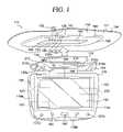
- FIG. 1is a perspective view of an embodiment of the video system and cradle.
- FIG. 2is an exploded view of the video system and cradle shown in FIG. 1 (with the cover for use when the video system is not in use shown).
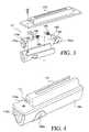
- FIG. 3is an exploded view of the projecting attachment member.
- FIG. 4is a perspective view of the projecting attachment member.
- FIG. 5is a front plan view of a video system in accordance with an alternate embodiment.
- FIGS. 6 , 7 and 8are respectively a plan view, perspective view and perspective view of a video system in accordance with an alternate embodiment of the system shown in FIG. 1 .
- FIGS. 9 , 10 and 11are various views showing an attachment mechanism in accordance with an alternate embodiment of the present invention.
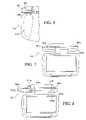
- FIG. 12is a perspective view of the rotation control mechanism, in its up (or storage) position, of the video system shown with reference to FIGS. 9 , 10 and 11 .
- FIG. 13is a perspective view of the rotation control mechanism in its down (or use) position, of the video system shown with reference to FIGS. 9 , 10 and 11 .
- FIG. 14is a schematic showing operation of the rotation control mechanism shown in FIGS. 12 and 13 .
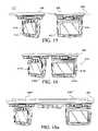
- FIGS. 15 , 16 , 17 , 18 and 18 ashow various multiple video system embodiments in accordance with the present invention.
- FIGS. 19 , 20 , 21 and 22are perspective views of various covers which may be used in accordance with the present invention.
- FIGS. 23 and 24are perspective views of the video system with profile members secured thereto.
- FIG. 25shows various video monitors of different sizes which may be selectively used in accordance with the present invention.
- FIGS. 26 , 27 and 28show the use of a forward facing video monitor in accordance with the present invention.
- FIG. 29shows an alternate embodiment of a camera for use in conjunction with the forward facing video monitor in accordance with the present invention.
- FIG. 30shows the video system of FIG. 1 mounted within a dash docking station.
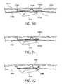
- FIG. 31shows the video system of FIG. 1 mounted within a mobile docking station.
- FIG. 32shows the video system of FIG. 1 mounted within a static docking station.
- FIG. 33is a top view of a dash mounted docking station in accordance with the present invention.
- FIG. 34is a front view of the docking station shown in FIG. 33 .
- FIG. 35is a side view of the docking station shown in FIG. 33 .
- FIGS. 36 , 37 and 38show the forward and rearward pivoting ability of the docking station shown in FIG. 33 .
- FIGS. 39 , 40 and 41show the lateral pivoting capabilities of the docking station shown with reference to FIG. 33 .
- FIGS. 42 , 43 and 44respectively show a rear view, side view and exploded perspective view of a portable docking station for use in accordance with the present invention.
- FIGS. 45 and 46show a touch panel screen in which command instructions are oriented based upon the orientation of the video monitor.
- FIG. 47shows an alternate embodiment of the feature presented with reference to FIGS. 45 and 46 .
- FIG. 48is a front plan view of the video system and cradle in accordance with the present invention.
- FIG. 49is a cross sectional view of the video system shown in FIG. 48 .
- FIG. 50is a cross sectional view showing the embodiment of FIGS. 48 and 49 installed within the ceiling of an automobile.
- FIGS. 51 and 52are cross sectional views showing various mounting structures for use in accordance with the present invention.
- an automobile entertainment system 110is disclosed.
- the automobile entertainment system 110is composed of a series of video and audio components integrated within an automobile 111 .
- the various embodiments of the present entertainment systemare disclosed herein with reference to their use within an automobile.
- the entertainment systemcould certainly be used in other vehicles, for example, boats or planes, without departing from the spirit of the present invention.
- a video system 112 and mounting structureare disclosed.
- the video system 112is adapted for selective mounting within the ceiling 113 of an automobile 111 . It is further contemplated those skilled in the art will appreciate the concepts underlying the present invention provide for the possibility of selectively mounting the video system within a variety of locations within an automobile, for example, the dashboard of an automobile.
- the video system 112is detachably mounted within a cradle 138 secured to the ceiling 113 of an automobile 111 .
- the video system 112generally includes a video monitor 116 for presenting media content and a video source 120 integrated therewith.
- the video sourceis a DVD player coupled to the video monitor 116 for the transmission of video content thereto.
- the DVD player, or other video source 120is integrated within the same video housing 118 as the video monitor 116 .
- a hard drive video source 123may be integrated with the video monitor 116 .
- the hard drive 123includes inputs for receiving video content and outputs for transmitting video content to the video monitor 116 , both of which are well known to those skilled in the art.
- the video sourcemay take a variety of other forms (for example, universal media disk) without departing from the spirit of the present invention.
- the video monitor 116 , DVD player 120 , hard drive 123 and associated control componentsare mounted within the housing 118 .
- the video monitor 116is a TFT LCD screen.
- other monitor constructionsfor example, plasma, Ultra High Definition VGA, touch screen VGA, organic LED, fabric based monitors (e.g., flexible TFT) etc., may be used without departing from the spirit of the present invention.
- the DVD player 120it is integrally molded within the housing 118 and positioned for insertion of the DVDs behind the video monitor 116 .
- the DVD player 120By mounting the DVD player 120 in this way, a stable structure is developed that is well adapted for the automobile environment. While the DVD player is disclosed as being a slot-loaded design with insertion behind the video monitor, the DVD player could take a variety of other forms without departing from the spirit of the present invention. Those skilled in the art will appreciate the various DVD designs that may be employed, for example, many can be seen in U.S. patent application Ser. No. 11/177,405, which is incorporated herein by reference.
- an alternate modular video system 112 ′is disclosed.
- the various componentsare not hardwired but are incorporated within the video system 112 ′ via interchangeable modules.
- the video system 112 ′is provided with a removable and interchangeable module 120 a ′ in which a hard disk drive, flash memory drive, DVD player/recorder, CD player/recorder, Blue Ray player/recorder, and an auxiliary battery may be incorporated.
- a hard disk drive, flash memory drive, DVD player/recorder, CD player/recorder, Blue Ray player/recorder, and an auxiliary batterymay be incorporated.
- other slot type modulesare utilized within the electronics industry and these may also be incorporated into the video system 112 ′.
- a slot for a PCMCIA Card and/or Ie:Cell.Air card 120 b ′ for downloading materialsmay be incorporated.
- memory cards 120 c ′ and USB cards 120 d ′may be incorporated into the video system 112 ′.
- the video system 112is detachably mounted within a cradle 138 formed in or secured to the ceiling 113 of the automobile 111 .
- the design of the video system 112 and cradle 138allows for the creation of multiple cradles 138 within an automobile, permitting selective positioning of the video system 112 at the various cradle locations within the automobile 111 .
- the base 164 of the video system 112is mounted to a cradle 138 formed within the ceiling 113 of the automobile 111 in a manner that permits rotation of the video housing 118 about multiple axes.
- the base 164includes a first hinge 166 that facilitates rotation of the video housing 118 about an axis substantially parallel to the ceiling 113 of the automobile 111 for movement from its upward storage position (see, for example, FIG. 12 ) to a downward use position (see, for example, FIG. 13 ) for viewing thereof.
- the first hinge 166is provided with a safety lock 210 .
- the safety lock 210is a latch member shaped and dimensioned to selectively interfere with rotation of the video system 112 about the first hinge 166 .
- the safety lock 210includes a user engagable handle 210 a allowing a user to move the safety lock 210 from its interference position blocking rotation of the video system 112 about the first hinge 166 to a release position.
- a biasing member 210 bforces the safety lock 210 back to its interference position.
- the safety lock 210will maintain the video system 112 in its storage position until such a time that a user desires to rotate the video system 112 about the first hinge 166 into its use position. In order to accomplish this rotation, the user must release the safety lock 210 by actuating the safety lock 210 and rotating the video system 112 from its storage position to its use position.
- the base 164further includes a second hinge 168 that permits rotation of the video housing 118 about an axis substantially perpendicular to the axis of the first hinge 166 .
- the second hinge 168allows for rotation of the video housing 118 in a manner that facilitates viewing of the video monitor 116 from opposite sides of the automobile 111 .
- the video system 112is, therefore, designed for rotation about multiple axes and may be freely rotated to improve viewing regardless of where the video system 112 is being used.
- the hinge structurealso includes a tensioning mechanism 212 .
- the tensioning mechanism 212is designed to permit free rotation of the video system 112 when desired, but apply preselected tension to the first and second hinges 166 , 168 for controlling vibration of the video system 112 as the automobile 111 moves and vibrations are transmitted throughout the automobile 111 .
- the tensioning mechanism 212also allows for controlled positioning of the video system 112 at a variety of angular orientations by simply releasing and reapplying the tensioning mechanism 212 .
- the tensioning mechanism 212includes a friction plate 212 a which selectively engages the first hinge 166 to hold the video system 112 in a desired orientation.
- the friction plate 212 ais attached to a handle 212 b which allows the user to move the friction plate 212 a between a tensioned orientation and an untensioned orientation.
- Similar frictional plates(not shown) are associated with the second hinge 168 for maintaining desired positioning.
- the base 164further includes a projecting attachment member 170 permitting selective coupling of the video system 112 within the automobile 111 .
- the attachment member 170includes a fastening mechanism 171 that permits secure and convenient attachment/removal of the video system 112 from the cradle 138 .
- the fastening mechanism 171includes first and second latch members 174 a , 174 b shaped and dimensioned for engaging respective first and second latching recesses 176 a , 176 b formed on opposite sides of the cradle 138 .
- the first and second latch members 174 a , 174 bare respectively actuated by primary release buttons 178 a , 178 b of the first and second latch members 174 a , 174 b positioned at opposite ends of the video system base 164 .
- the first and second latch members 174 a , 174 bdisengage from the first and second recesses 176 a , 176 b , permitting the removal of the video system 112 from the cradle 138 .
- first and second safety buttons 180 a , 180 bwhich selectively lock the first and second latch members 174 a , 174 b in their latched position. More particularly, each of the first and second safety buttons 180 a , 180 b include an obstructing member 182 , which sits within the path of the first and second latch members 174 a , 174 b preventing movement thereof.
- Each of the obstructing members 182includes a release aperture 184 which aligns with a projection 186 of the respective latch members 174 a , 174 b when the safety buttons 184 a , 184 b , are pressed to permit movement of the latch member 174 a , 174 b and release of the video system 112 .
- Each of the first and second safety buttons 180 a , 180 bis spring biased via a spring 188 to ensure they remain in their safety position unless intentionally pushed to permit movement of the first and second latch members 174 a , 174 b.
- the appearance of the video system 312 ′may be further enhanced by integrating the safety buttons 380 a , 380 b with cover plates 381 a , 381 b positioned at the opposite ends of the base 364 .
- rotation of the cover plates 381 a , 381 bactuates the safety button 380 a , 380 b to permit actuation of the first and second latch members 374 a , 374 b and reveal the first and second release buttons 378 a , 378 b.
- first and second latch members 374 a , 374 bmay be actuated simultaneously to permit removal of the video system 312 from the cradle 138 .
- first and second latch members 374 a , 374 bmay be actuated simultaneously to permit removal of the video system 312 from the cradle 138 .
- latching structuresmay be employed without departing from the spirit of the present invention.
- the cradle 138is shaped and dimensioned for receiving and securing the video system 112 to the ceiling 113 of the automobile 111 .
- similar cradlesmay be provided at other locations permitting use of the video system 112 at other remote locations within the same automobile or in other automobiles.
- the cradle 138 utilized in accordance with a preferred embodiment of the present inventionincludes quick release electrical connections 142 for the audio input 122 , audio output 124 , video input 126 , video output 128 and power supply 130 (although one embodiment contemplates a system which connects only to a power supply).
- the video system 112and particularly, the base 164 of the video system 112 , includes mating electrical connections 144 for transmitting electricity and a/v signals between the cradle 138 and the video system 112 .
- the respective electrical connections 142 , 144mate to provide for the transmission of power and a/v signals between the video system 112 and the cradle 138 .
- other readily removable electrical connections for other purposesmay also be supplied.
- the cradle 138also includes a fastening mechanism 172 adapted for selective engagement with the fastening mechanism 171 of video system 112 .
- the fastening mechanism 172 of the cradle 138is composed of a primary recess 193 into which the projecting attachment member 170 of the base 164 of the video system 112 may be positioned.
- the fastening mechanism 172 of the cradle 138also includes the first and second latching recesses 176 a , 176 b that are shaped and dimensioned for selectively and securely coupling with the first and second latch members 174 a , 174 b of the video system base 164 .
- the primary recess of the cradle and the projecting attachment member of the basemay be formed in a variety of shapes so long as they are designed to provide for a secure attachment with very little play between the attached components.
- each cradle 138 installed with an automobile 111is positioned such that the face plate 192 is substantially flush with the headliner 194 , or other automobile surface, directly adjacent thereto.
- the cradle 138is constructed with a metal mounting plate 196 directly secured to the ceiling 113 of the automobile 111 and a ceiling docking port 198 secured thereto.
- the face place 192is formed as part of the ceiling docking port 198 .
- the ceiling docking port 198includes the electrical and mechanical components discussed above which allow for the direct attachment of the video system 112 thereto.
- the base 464includes first and second projecting attachment members 470 a , 470 b shaped and dimensioned to engage respective first and second apertures 476 a , 476 b formed in the cradle 438 .
- the first and second projecting attachment members 470 a , 470 beach include an upwardly extending post 472 a , 472 b with a resilient spring latch 474 a , 474 b formed thereon.
- the spring latches 474 a , 474 bare actuated to control passage through the respective first and second apertures 476 a , 476 b during installation and removal.
- first and second projecting attachment members 470 a , 470 bwill only provide limited support.
- the video system 412is provided with eccentric shaped first and second locking members 478 a , 478 b and the cradle 438 is similarly provided with eccentric shaped first and second locking apertures 480 a , 480 b .
- the first and second locking members 478 a , 478 bare shaped to pass through respective first and second locking apertures 480 a , 480 b formed in the cradle when the shapes of the first and second locking members 478 a , 478 b and the first and second locking apertures 480 a , 480 b align.
- first and second locking members 478 a , 478 bare passed through the first and second locking apertures 480 a , 480 b , the first and second locking members 478 a , 478 b are rotated such that the shape of the first and second locking members 478 a , 478 b no longer align with the first and second locking apertures 480 a , 480 b , and the video system 412 is thereby locked relative to the cradle 438 .
- the attachment mechanismis further enhanced with first and second safety buttons 482 a , 482 b associated with the first and second projecting attachment members 470 a , 470 b .
- the first and second safety buttons 482 a , 482 brespectively control actuation of the spring latches 474 a , 474 b extending from the projecting attachment members 470 a , 470 b so that the video system 412 may not be removed until the respective safety buttons 482 a , 482 b are simultaneously actuated.
- the first and second safety buttons 482 a , 482 bcause controlled expansion and/or contraction of the spring latches 474 a , 474 b to permit or restrict passage of the spring latches 474 a , 474 b through the first and second apertures 476 a , 476 b .
- the safety buttons 482 a , 482 bcontrol expansion and/or contraction of the spring latches 474 a , 474 b by selectively drawing the spring latches 474 a , 474 b inward in a manner making them narrower, and thereby allowing for passage through the first and second apertures 476 a , 476 b .
- third and fourth safety buttons 484 a , 484 bare associated with the first and second locking members 478 a , 478 b and prevent rotation of the first and second locking members 478 a , 478 b until the first and second safety buttons 484 a , 484 b are simultaneously actuated.
- This embodimentalso includes a tensioning mechanism 512 with a handle friction plate 512 a and handle 512 b .
- the cradleis secured to a lateral beam running along the roof of the automobile.
- the orientation of the fastening mechanism componentsis critical to the operation and installation of the present video system.
- the base 464 of the video systemincludes first and second projecting attachment members 470 a , 470 b shaped and dimensioned to engage respective first and second apertures 476 a , 476 b formed in the cradle 438 .
- the base 464 of the video system 412also includes eccentric shaped first and second locking members 478 a , 478 b and the cradle 438 is similarly provided with eccentric shaped first and second locking apertures 480 a , 480 b .
- Between the respective attachment members, locking members and aperturesare electrical connections, which are discussed below in greater detail, linking the video system to the cradle (and the remainder of the automobile).
- the spacing of the various fastening components relative to the electrical connections 442 , 444is critical to placement of the cradle 438 , and ultimately the video system 412 , along the beams, for example, the B-pillar 560 (see FIG. 15 ), formed in the roof of an automobile.
- the inner edge 481 a , 481 b , 479 a , 479 b of the outer most fastening componentis preferably approximately 1 ⁇ 8 inch to approximately 7 inches from the respective outer edge 443 a , 443 b , 445 a , 445 b of the electrical connection 442 , 444 , and more preferably approximately 2 inches to approximately 4 inches from the outer edge 443 a , 443 b , 445 a , 445 b of the electrical connection 442 , 444 .
- the respective inner edges 481 a , 481 b of the first and second locking apertures 480 a , 480 bare preferably approximately 1 ⁇ 8 inch to approximately 7 inches from the respective first and second outer edges 443 a , 443 b of the electrical connections 442 , and more preferably approximately 2 inches to approximately 4 inches from the respective first and second outer edges 443 a , 443 b of the electrical connections 442 .
- the respective inner edges 479 a , 479 b of the locking members 478 a , 478 bare preferably approximately 1 ⁇ 8 inch to approximately 7 inches from the respective first and second outer edges 445 a , 445 b of the electrical connection 444 , and more preferably approximately 2 inches to approximately 4 inches from the respective first and second outer edges 445 a , 445 b of the electrical connection 444 .
- the base 464 of the video system 412is mounted to a cradle 438 formed within the ceiling 413 of the automobile 411 in a manner that permits rotation of the video housing 418 about multiple axes. More particularly, the base 464 includes a first hinge 466 that facilitates rotation of the video housing 418 about an axis substantially parallel to the ceiling 413 of the automobile 411 for movement from its storage (or up) position to a downward use position for viewing thereof. In an effort to provide for controlled rotation of the video monitor 416 about an axis substantial parallel to the ceiling of the automobile, the first hinge 466 is provided with a rotation control mechanism 520 .
- the rotation control mechanism 520adjusts the storage position of the video system 412 for alignment with the ceiling 413 , in particular, the headliner 494 , of the automobile 411 .
- the present rotation control mechanism 520allows for ready adjustment of the present video system 412 permitting optimized installation and usage of the present system.
- the rotation control mechanism 520 of the first hinge 466includes a first detent adjustment wheel 522 designed for limiting the position of the video system 412 as it is moved to its use position and a second detent adjustment wheel 524 designed for limiting the position of the video system 412 as it is moved to its storage position. Both the first detent adjustment wheel 522 and the second detent adjustment wheel 524 are in alignment with the pivot pin 526 of the first hinge 466 , providing an ideal location for control of the rotation of the video system.
- a first detent notch 528is associated with the first detent adjustment wheel 522 .
- the first detent notch 528is shaped and dimensioned to interact with a first detent 530 extending laterally from the housing 418 and in substantial alignment for interaction with the first detent notch 528 .
- the first detent 530will ultimately contact the first detent notch 528 , seat therein and substantially prevent further movement of the housing 418 .
- the first detent adjustment wheelmay be provided with multiple detent notches in which the first detent is selectively seated based upon the desired viewing angle.
- the first detent 530is biased by spring 532 toward the first detent notch 528 . Release, thereof, is provided by a button 534 linked to the first detent 530 permitting withdrawal of the first detent 530 from the first detent notch 528 .
- the second detent adjustment wheel 524includes a second detent notch 536 associated therewith.
- the second detent notch 536is shaped and dimensioned to interact with a second detent 538 extending laterally from the housing 418 and in substantial alignment for interaction with the second detent notch 536 .
- the second detent 538will ultimately contact the second detent notch 536 , seat therein and substantially prevent further movement of the housing 418 .
- the second detent 538is biased by a spring 539 toward the second detent notch 536 . Release, thereof, is provided by a button 540 linked to the second detent 538 permitting withdrawal of the second detent 538 from the second detent notch 536 .
- the first and second adjustment wheels 522 , 524are secured to the first hinge 466 for movement relative thereto for ultimately controlling the position of the first and second detent notches 528 , 536 .
- the first and second adjustment wheels 522 , 524are designed to permit selective rotation relative to the first hinge 466 for adjusting the desired stop points, but are generally fixed during usage thereof such that as the housing 418 of the video system 412 is rotated about the first hinge 466 , the stop points will remain consistent and reliable.
- a retaining mechanismfor example, a magnet system, 1721 may be used to hold the video system 1712 close to the headliner 1794 of the automobile 1711 . That is, the retaining mechanism maintains the video system 1712 adjacent the headliner 1794 and the cradle 1738 when it is in its storage position. Such a system will help in preventing shaking and other undesirable movement of the video system 1712 .
- a magnet systemfor example, a magnet system
- the mounting bracket 1739 securing the cradle 1738 adjacent the ceiling 1713 , and ultimately the video system 1712is provided with a magnetically active metal portion 1797 a that aligns with magnets 1797 b formed in the video system 1712 when the video system 1712 is rotated to its storage position.
- FIGS. 51 and 52it is further contemplated other mechanisms for holding the video system close to the headliner may be employed.
- the conventional magnets disclosed with reference to FIGS. 48 , 49 and 50may be replaced with electromagnets 1897 a , 1897 b .
- the electromagnets 18997 a , 1897 b within the headliner 1894 and the video system 1812are activated to drawn the video system 1812 toward the headliner 1894 such that it is securely stored at its storage position.
- a latch 1999is provided for extension from the cradle 1939 and through the headliner 1994 .
- the latch 1999is designed to rotate forward to a position for engaging the video system 1912 when the video system 1912 is rotated to its storage position.
- the base 464further includes a second hinge 468 that permits rotation of the video housing 418 about an axis substantially perpendicular to the axis of the first hinge 466 .
- the second hinge 468allows for rotation of the video housing 418 in a manner that facilitates viewing of the video monitor 416 from opposite sides of the automobile 411 .
- the video system 412is, therefore, designed for rotation about multiple axes and may be freely rotated to improve viewing regardless of where the video system 412 is being used.
- the hinge structurealso includes a tensioning mechanism 512 .
- the tensioning mechanism 512is designed to permit free rotation of the video system 512 when desired, but apply preselected tension to the first hinges 466 for controlling vibration of the video system 412 as the automobile moves and vibrations are transmitted throughout the automobile.
- the tensioning mechanism 512also allows for controlled positioning of the video system 412 at a variety of angular orientations by simply releasing and reapplying the tensioning mechanism 512 .
- the tensioning mechanism 512includes a friction plate 512 a that selectively engages the first hinge 466 to hold the video system 412 in a desired orientation.
- the friction plate 512 ais attached to a handle 512 b that allows the user to move the friction plate 512 a between a tensioned orientation and an untensioned orientation.
- Similar frictional plates(not shown) are associated with the second hinge for maintaining desired positioning.
- a similar tensioning mechanismmay be applied to the second hinge 468 .
- the present cradle 438 /video system 412has been developed so as to ensure only approved and compatible video systems may be used when placed within a cradle manufactured in accordance with the present invention.
- the cradle 438is provided with an RF identification transceiver 542 that interacts with a similar RF identification transceiver 544 mounted within, for example, the base 464 of the video system 412 .
- the electrical connections 442 of the cradle 438are linked to the RF identification transceiver 542 and will remain closed until a video system 412 with an appropriate RF identification transceiver 544 is placed within the cradle 438 .
- Controlled use of the cradle and video systemmay further be achieved via direct electrical communication between the cradle and the video system.
- the cradle and video systemcould be provided with respective electrical connections that permit usage only when the electrical connection is complete.
- the cradle 438is shaped and dimensioned for receiving and securing the video system 412 to the ceiling of the automobile. As those skilled in the art will certainly appreciate, similar cradles may be provided at other locations permitting use of the video system 412 at other remote locations.
- various cradles 438may be mounted within an automobile for receiving video systems 412 in a manner permitting viewing from different locations within the automobile.
- cradles 438may be positioned along the same B-pillar 560 at laterally spaced positions within the automobile as shown in FIG. 15 and/or cradles may be positioned along different B-pillars spaced along the length of the automobile.
- a dual monitor system 410 ′, 410 ′′, 410 ′′′is contemplated in accordance with the present invention as shown with reference to FIGS. 16 , 17 and 18 .
- the dual monitor systems 410 ′, 410 ′′, 410 ′′′include respective first and second monitors 416 a ′, 416 a ′′, 416 a ′′′, 416 b ′, 416 b ′′, 416 b ′′′ and first and second video sources (not shown) mounted with first and second housings 418 a ′, 418 a ′′, 418 a ′′′, 418 b ′, 418 b ′′, 418 b ′′′.
- Each of the housings 418 a ′, 418 a ′′, 418 a ′′′, 418 b ′, 418 b ′′, 418 b ′′′is linked to a single base 464 ′, 464 ′′, 464 ′′′ from which the first and second housings 418 a ′, 418 a ′′, 418 a ′′′, 418 b ′, 418 b ′′, 418 b ′′′ extend.
- Pivotal connections linking the first and second housings 418 a ′, 418 a ′′, 418 a ′′′, 418 b ′, 418 b ′′, 418 b ′′′ to the base 464 ′, 464 ′′, 464 ′′′allow for rotation of the first and second housings 418 a ′, 418 a ′′, 418 a ′′′, 418 b ′, 418 b ′′, 418 b ′′′ between a storage positioned and a use position.
- a dual monitor system 410 ′′′′may be provided which connects with two cradles 438 ′′′′ mounted along the same B-pillar 560 ′′′′.
- the cradle 438includes quick release electrical connections 442 for the audio input, audio output, video input, video output and power supply (although one embodiment contemplates a system which connects only to a power supply).
- the video system 412and particularly, the base 464 of the video system 412 , includes mating electrical connections 444 for transmitting electricity and a/v signals between the cradle 438 and the video system 412 .
- the cradle 438also includes a various fastening apertures 476 a , 476 b , 480 a , 480 b adapted for selective engagement with the attachment members 470 a , 470 b , 478 a , 478 b of video system 412 .
- the usefulness of the present inventionis enhanced by the fact that the cradle 438 is substantially recessed within the ceiling 413 of the automobile 411 . More particularly, each cradle 438 installed with an automobile 411 is positioned such that the face plate 492 is substantially flush with the headliner 494 , or other automobile surface, directly adjacent thereto.
- the cradle 438is constructed with a metal mounting plate 496 directly secured to the ceiling 413 , more particularly, the B-pillar 560 (see FIG. 15 ), of the automobile 411 and a ceiling docking port 498 secured thereto.
- the ceiling docking port 498includes the electrical and mechanical components discussed above which allow for the direct attachment of the video system 412 thereto.
- the installation of the cradle 138 , 438is intended to provide for an aesthetically pleasing appearance and the ceiling docking port 198 , 498 is, therefore, provided with a face plate 192 , 492 which substantially aligns with and is, therefore, flush with the headliner 194 , 494 of the automobile 111 .
- the following disclosureapplies to both embodiments of the video system presented above, although only the first embodiment shown in FIGS. 1 to 4 is referenced herein. Aesthetics are further enhanced by the provision of a cover member 200 , 200 ′, 200 ′′ which may be selectively placed over the ceiling docking port 198 when it is not in use.
- cover member 200 , 200 ′, 200 ′′are designed to substantially conform with the color, fabric, texture etc. of the headliner 194 , 494 .
- the cover memberis further designed to be substantially flush with the headliner and conform with the profile thereof.
- the cover member 200 , 200 ′, 200 ′′is preferably frictionally engaged with docking port 198 when positioned for covering.
- the cover member 200 , 200 ′, 200 ′is provided with snap connections 210 , 210 ′, 210 ′′ shaped and dimensioned for engagement with the cradle 138 , 438 .
- the cover membermay be a simple cover 200 (see FIG. 19 ), a powered cover 200 ′ with various power sources 202 ′ extending therefrom (see FIG. 20 ) or an illuminating cover 200 ′′ with lights 202 ′′ (see FIG. 21 ). Where the covers require power, the cover is provided with an electrical connection 244 ′, 244 ′′ allowing the cover 200 ′, 200 ′′ to tap into the power supply of the cradle 438 .
- FIG. 22Another cover 200 ′′′ employing a rear seat, or baby, camera 202 ′′′ is also contemplated as shown in FIG. 22 .
- the cover 200 ′′′includes a rearwardly facing video camera 202 ′′′ linked to a video monitor either integrated within the rearview mirror of the automobile or independently mounted along the dash of the automobile.
- a drivermay keep an eye on what is going on in the backseat of an automobile without constantly turning around to view the rear seats of the vehicle.
- the video camera 202 ′′′is linked to the video monitor via the electrical connections 244 ′′′ of the cover 200 ′′′ and the cradle 138 , which are ultimately linked to the video monitor via wired or wireless means known to those skilled in the art.
- the video monitoritself may be provided with a rearwardly facing video camera performing the same function as the video camera mounted within the cover.
- the cover 200 ′′′may also be provided with a Bluetooth processor 204 ′′′ programmed to interact with a variety of Bluetooth appliances that might be brought into the automobile.
- the Bluetooth processor 204 ′′′might provide for hands-free cell phone usage, wireless Internet access for those bringing a Bluetooth enable laptop into the automobile, etc. Additional functionalities may include, for example, and not limited to, those discussed herein with regard to the use of an expansion slot.
- the aesthetically pleasing nature of the present embodimentis further enhanced by the provision of a “free floating” video system 112 , 412 .
- the housing 118 , 418 with the video monitor 116 , 416 and video source 120 , 420 housed thereindepends from the base 164 , 464 which is then mounted to the recessed cradle 138 , 438 formed within the ceiling of the automobile.
- the video system 112 , 412depends from the ceiling integrated cradle 138 , 438 without the need for a surrounding support structure, allowing for the provision of a self-sufficient video system 112 , 412 .
- the video system 112 , 412when the video system 112 , 412 is rotated to its storage position, it is substantially parallel and adjacent the headliner 194 , 494 with no support structure surrounding the unattached outer perimeter, that is, the free side edges 119 a - c , 419 a - c to which the base 164 , 464 is not attached, of the housing 118 , 418 .
- Thisimproves the aesthetics of the video system 112 , 412 and does not require that a substantial portion of the headliner 194 , 494 be covered or cut away to accommodate the installation thereof.
- the “free floating” video system 612 of the present inventionis further enhanced by providing selectively attachable profile members 714 to the free side edges 619 a - c of the housing 618 .
- the profile members 714are designed to substantially conform to the headliner 694 shape of the vehicle such that when the video system 612 is rotated to its storage position as shown in FIG. 24 , the video system 612 will substantially conform with the headliner 694 in an aesthetically pleasing manner.
- the video system 612may be readily adapted to conform to the headliner 694 profile of a variety of vehicles by simply replacing the profile members 714 .
- Selective attachment of the profile members 714is achieved by the provision of mating coupling members 716 , 718 formed along the connecting surfaces of the profile members 714 and the housing 618 . While a variety of coupling members may be utilized in accordance with the present invention, the preferred coupling members will be engaging male and female latch members formed along the connecting surfaces of the profile members and the housing.
- the fact that no support structure surrounds the video systemallows for the ready replacement of the video system with other video systems 812 a , 812 b , 812 c of differing sizes and shapes (see FIG. 25 ).
- a drivermay choose to use various different video systems of different sizes depending upon the needs of the driver.
- a dealer or installercan sell the same system at different prices depending upon the size of the monitor required by the customer.
- the video system 812is provided with a rearwardly facing video camera 938 , 938 a and a forward facing video monitor 932 .
- the video system 812includes a rear facing surface 934 from which the video monitor 816 discussed above projects images for viewing by passengers of the automobile 811 .
- the video systemalso includes a front facing surface 936 .
- a forward facing video monitor 932is provided on the front facing surface 936 for alignment with the rearview mirror 802 and viewing by the driver when the video system 812 is in its use position.
- the forward facing video monitor 932is linked to a video camera 938 mounted along the rear facing surface 934 of the video system 812 (see FIGS. 26 to 28 ) or a video camera 938 a mounted along the rear portion 940 of the automobile 811 (see FIG. 29 ).
- a video camera 938mounted along the rear facing surface 934 of the video system 812 (see FIGS. 26 to 28 ) or a video camera 938 a mounted along the rear portion 940 of the automobile 811 (see FIG. 29 ).
- the systemis activated and the video camera 938 , 938 a is positioned to look out the rear window 804 of the automobile 811 .
- the image generated by the video camera 938 , 938 ais then transferred to the forward facing video monitor 932 where the driver may look at the image as he or she looks in the rearview mirror 802 .
- activation of the systemis linked to rotation of the video system 812 from a storage position substantially parallel with the ceiling of the automobile 811 to a use position rotated away from the ceiling of the automobile.
- the video system 812is provided with a switch 813 that identifies rotation from a storage position to a use position and accordingly activates the video camera 938 , 938 a and forward facing video monitor 932 for viewing behind the automobile 811 .
- the video cameras 938 , 938 amay be used in tandem are separately.
- the video camera discussed above with reference to FIGS. 26 to 29may be linked to a video monitor positioned for direct viewing by the automobile driver.
- the video monitorwould be integrated within the rearview mirror of the automobile so that the driver will need only look to the rearview mirror in the manner he or she would normally look to the rearview mirror for viewing behind the automobile.
- the video camera 938 within the video system 812may be positioned to monitor the back seats of the vehicle in addition to, or in conjunction, with the rearview traffic. This could be achieved by moving the camera 938 , or utilizing multiple cameras, such that both views of the rearview traffic and the backseats are shown upon the forward facing video monitor 932 .
- cables 132extend through the ceiling 113 and the cradle 138 . These cables 132 ultimately link audio, video and power to the cradle 138 and video system 112 . More specifically, the cradle 138 and video system 112 are electrically connected to the remainder of the automobile 111 via electrical communication lines in a manner known to those skilled in the art.
- the present video system 112is provided with the ability to offer a variety of functionalities. These functionalities may be hardwired or programmed within the video system 112 or the functionalities may be added in a modular manner via an expansion slot 140 provided within the video system 112 .
- Contemplated functionalitiesinclude, but are not limited to satellite radio (for example, Serius, XM), Pictel phone, satellite television (for example, DirecTV), GPS guidance systems, quick release battery packs, memory cards, wireless internet access (for example, Wi-Fi), Bluetooth, digital video recorders, digital video reception and recording, digital video inputs, video conferencing, cellular digital, cellular digital with a camera, USB capabilities, Blue sphere, Blu-ray technology, hot swap hard drive, satellite video import card, wireless video import card, supplemental hard drive, flash memory accessibility, wireless download capabilities, PCICM slots, etc.
- the video systemmay also be provided with a flashlight 135 controlled by an on/off switch 135 a , which runs off a battery 220 mounted within the video system 112 .
- the video system 112may further be provided with both a 110 A power outlet 137 a and a 12 V power outlet 137 b for connection with other electronic devices requiring power.
- the video system 112is provided with a battery 220 .
- the battery 220is preferably a rechargeable battery and, as such, will be regularly recharged when the video system 112 is mounted within the cradle 138 and coupled to the power supply running therethrough.
- USB portsAs shown best with reference to the video system 412 as shown in FIG. 45 , enhanced usage is further provided by the inclusion of USB ports, flash memory slots, cellular card slots, IR transmitters, RCA ports, power buttons or other a/v input/outputs, formed within the housing 418 of the video system 412 and contained behind cover 418 a , 418 b which may be selectively opened to reveal the ports and slots.
- the inclusion of these portsallows for ready attachment of the present video system to other remote a/v sources (for example, game consoles, portable digital music players, etc.). It is also contemplated such ports, slots and other accessories may be integrated with the cradle.
- a broadcast television receiver and antennamay be integrated with the video monitor as discussed in U.S. patent application Ser. No. 11/177,405, which is incorporated herein by reference and/or the headrest.
- Control of the video system 112is facilitated by the provision of control buttons along the outer surface of the video system 112 .
- the control buttonstake the form of a multifunction controller 160 permitting movement of a cursor shown upon various interfaces displayed upon the video in a well known manner.
- conventional control buttons 162may also be provided for control of traditional functions.
- the video system 112may further include a remote control (not shown) such that an individual need not actually touch the video system 112 to control the video system 112 .
- the present video system 112(whether it be the video system disclosed with reference to FIGS. 1 to 4 or that disclosed with reference to the various other embodiments) is adapted for removal from the ceiling cradle 138 of an automobile 111 for use at a variety of other locations.
- the other locationsare provided with docking stations 1050 , 1150 , 1250 including auxiliary cradles 1038 , 1138 , 1238 shaped and dimensioned for receiving the video system 112 and coupling the video system 112 to power sources and a/v sources in a manner similar to the cradle 138 used in conjunction with the ceiling 113 (see FIGS. 30 , 31 and 32 ).
- a docking station 1050 for use in conjunction with the dash 1052 of a conventional automobile 1011is shown.
- the docking station 1050includes an auxiliary cradle 1038 (with electrical connections and a connecting mechanism (not shown)) shaped and dimensioned for receiving and securely holding the video system 112 and coupling the video system 112 to power sources and a/v sources in a manner similar to the cradle 138 used in conjunction with the ceiling 113 .
- the docking station 1050is mounted upon the dash 1052 of an automobile 1011 and is wired for connection to a power source and a/v sources.
- the dash docking station 1050may include an integrated satellite receiver 1054 for providing satellite content to the passengers of the automobile 1011 by transmitting the satellite signal through the cradle 1038 and into the video system 112 via the respective electrical connections of the cradle 1038 and the video system 112 .
- This embodimentis particularly useful where the video system 112 includes functionality relating to the provision of GPS guidance information.
- the driverwill be able to selectively use the video system 112 for accessing guidance information when needed and return the video system 112 to the ceiling cradle 138 when guidance information is no longer needed.
- a mobile docking station 1150may also be provided.
- the mobile docking station 1150also includes an auxiliary cradle 1138 (with electrical connections and a connecting mechanism (not shown)) shaped and dimensioned for receiving and securely supporting the video system 112 and coupling the video system 112 to power sources and a/v sources in a manner similar to the cradle 138 used in conjunction with the ceiling.
- the docking station 1150may include a battery pack 1155 , a/v inputs 1156 , a/v outputs 1157 , Internet capability, speakers 1158 , cable input 1159 and/or an integrated satellite receiver 1154 . These components are linked to the video system 112 via the cradle 1138 which transmits the relevant signals to and from the video system 112 via the respective electrical connections of the cradle 1138 and the video system 112 .
- the video system 112when the video system 112 is mounted to the docking stations 1050 , 1150 , it may be necessary to mount the video system 112 upside down when compared to its mounting within an automobile 111 .
- the video system 112is provided with the ability to rotate to the image shown on the video monitor 116 so that the video system 112 may be used in a variety of orientations.
- the possible rotation of the image shown on the video monitor 116is complemented by the multifunctional controller 160 that adjusts to the rotation of the image such that the controller 160 is calibrated to function in accordance with the orientation of the screen image.
- a docking station 1250is disclosed.
- This docking station 1250is adapted for static mounting within a household, office or other locations (for example, beneath a kitchen cabinet 853 ).
- the docking station 1250includes an auxiliary cradle 1238 (with electrical connections and a connecting mechanism (not shown)) shaped and dimensioned for receiving and securely supporting the video system 112 and coupling the video system 112 to power sources and a/v sources in a manner similar to the cradle 138 used in conjunction with the ceiling.
- the docking station 1250may include a battery pack 1255 , a/v inputs 1256 , a/v outputs 1257 , Internet capability, speakers 1258 , cable input 1259 and/or an integrated satellite receiver 1254 . These components are linked to the video system 112 via the cradle 1238 which transmits the relevant signals to and from the video system 112 via the respective electrical connections of the cradle 1238 and the video system 112 .
- the present inventionis adapted for utilization in conjunction with a dash mounted docking station.
- various state and local regulationsprohibit the utilization of a front seat mounted video system wherein the driver of the vehicle is exposed to video entertainment.
- these state and local regulationsdo not prohibit a video display that provides the driver with useful information regarding the operation and performance of his or her vehicle, as well as navigation information provided with current GPS navigation systems.
- the docking station 1350 disclosed with reference to FIGS. 33 to 41is specifically adapted for utilization and mounting upon the dash 1352 of a conventional automobile 1311 .
- the docking station 1350is designed such that the video system 112 will provide only navigation-based displays when directed toward the driver of the automobile 1311 and will provide all video functionalities when oriented toward the passenger of the automobile 1311 .
- the docking station 1350includes a base 1360 upon which is mounted a cradle 1338 .
- the base 1360is shaped and dimensioned for secure attachment to the dash 1352 of an automobile 1311 using conventional brackets and coupling structures known to those skilled in the art.
- the cradle 1338is pivotally mounted upon the base 1360 for movement about multiple axes.
- the cradle 1338is shaped and dimensioned to receive and support the video system 112 .
- the cradle 1338is provided with quick release electrical connections 1342 for the audio input 1322 , audio output 1324 , video input 1326 , video output 1328 and power supply 1330 .
- the video system 112similarly includes mating electrical connections 144 for transmitting electricity and AV signals between the cradle 1338 and the video system 112 .
- the respective electrical connections 144 , 1342mate to provide for the transmission of power and AV signals between the video system 112 and the cradle 1338 .
- other readily removable electrical connections for other purposesmay also be supplied if one determines they are so needed.
- the cradle 1338also includes a connecting mechanism 1362 designed for selectively retaining the video system 112 within the cradle 1338 .
- a connecting mechanism 1362designed for selectively retaining the video system 112 within the cradle 1338 .
- a snap mechanismwell known to those skilled in the industry will be used in selectively securing the video system within the cradle, although other coupling structure may be used without departing from the spirit of the present invention.
- the connecting mechanism 1362permits ready and selective attachment of the video system 112 to the docking station 1350 while preventing vibrations and other damaging movements that may occur in an automobile.
- the connecting mechanismmay take a variety of forms known to those skilled in the art.
- a first pivotal coupling 1364allows for forward and rearward tilting of the cradle 1338 to allow a viewer to adjust the viewing angle at which the video system 112 is oriented.
- the base 1360is provided with a second pivotal coupling 1366 allowing the cradle 1338 to be rotated about an axis extending substantially perpendicular to the base 1360 and providing for transverse rotation of the cradle 1338 .
- This rotationallows the video system 112 to be selectively oriented for viewing by either the driver or the passenger in the front seat. Movement of the cradle 1338 about this axis is controlled by a release mechanism 1368 which allows one to selectively move the cradle 1338 about the second pivotal coupling 1366 and subsequently lock it in a desired position.
- a two stage release mechanismknown to those skilled in the art will be used in an effort to enhance safety, although other release structures known within the art may be employed without departing from the spirit of the present invention.
- the cradle 1338(and ultimately the video system 112 via the electrical connections 144 and 1342 ) is electrically coupled to the second pivotal coupling 1366 via a switch 1370 so that it may signal the video system 112 as to the specific orientation of the cradle 1338 ; that is, whether the cradle 1338 is oriented for viewing by the driver or for by viewing of a passenger within the front seat.
- the switch 1370signals the video system 112 that it is oriented for viewing by the driver and the video system 112 may, therefore, only display navigation based information.
- Control of these instructionsis provided via the switch 1370 contained within the second pivotal coupling 1366 , as well as the microprocessor 1374 controlling operation of the video system 112 .
- the switch 1370is once again activated and the video system 112 is instructed that the cradle 1338 is oriented for viewing by the passenger within the front seat of the automobile 1311 .
- this instructionis provided, the video system 112 is then able to perform all functionalities associated therewith.
- the functionalitiesmay include, but are not limited to the various functions previously discussed with relation to the prior embodiments.
- the docking station 1350may further include a battery pack, AV inputs, AV outputs, Internet capabilities, speakers, cable input, and/or integrated satellite receivers.
- the concepts underlying the present docking stationmay be employed with a system wherein the video system is integrated with the docking station, and is, therefore, designed only for use as a dash-mounted video system.
- a portable docking station 1400is disclosed with reference to FIGS. 42 , 43 and 44 .
- this portable docking station 1400includes a cradle 1430 shaped and dimensioned for receiving the video system 412 (although the present disclosure applies equally to the other video system embodiments disclosed herein) and coupling the video system 412 to power sources and a/v sources in a manner similar to the cradle used in conjunction with the ceiling.
- the docking station 1400includes a housing 1402 in which a cradle 1430 is positioned at a first end 1404 thereof.
- the cradle 1430includes fastening structures similar to those disclosed above with reference to FIGS. 9 , 10 and 11 to permit selective attachment of the video system 412 thereto.
- the housing 1402further includes a handle 1406 adjacent the cradle 1430 for carrying the video system 412 in a convenient and comfortable manner.
- this portable docking station 1400includes inputs 1450 , 1452 for connection to a power source and a/v sources.
- the docking station 1400includes a battery 1455 for additional power storage for use when now hardwired power source is readily available.
- the docking station 1400also includes Internet capability, speakers 1458 , cable input 1459 and/or an integrated satellite receiver 1460 . These components are linked to the video system 412 via the cradle 1430 which transmits the relevant signals to and from the video system via the respective electrical connections of the cradle and the video system.
- FIGS. 45 and 46A further feature of the present invention is disclosed with reference to FIGS. 45 and 46 .
- the potential that the video system may be utilized in a variety of orientationsis addressed by providing a video system 1512 with a video monitor 1516 having a touch screen VGA panel 1517 .
- the video system 1512also includes a touch panel control system 1560 that “flips” the graphical user interface control panel 1576 when the video system 1512 is positioned in a specific orientation.
- the microprocessor 1572 of the video system 1512is provided with an orientation sensor 1574 .
- the orientation sensor 1574instructs the microprocessor 1572 as to the orientation of the video system 1512 .
- a graphical user interface control panel 1576provided upon the touch screen panel 1517 of the video system 1512 orients itself for viewing and actuation by a user. For example, and with reference to FIG. 45 , when the video system 1512 is oriented with the electrical connections 1544 facing downwardly, for example, when used in a dash docking station, the control panel 1576 is provided in a horizontal orientation properly positioned for viewing by the automobile passenger.
- the orientation sensor 1574senses that the video system 1512 is oriented in this configuration and instructs the microprocessor 1572 to provide the touch screen panel 1517 with a control panel 1576 the opposite of those shown with reference to FIG. 45 (see FIG. 46 ).
- This featureobviates the need for users of the present system to read upside down instructions when the video system 1512 is provided with a touch screen mechanism.
- the orientation adjustment feature of the video system 1612may also be implemented manually through the inclusion of a switching button 1674 which will instruct the microprocessor 1672 and touch panel control system 1660 to orient the control panel 1676 in a desired orientation.
- the video monitormay be supplemented with the use of Sharp's dual screen monitor technology.
- Sharp's dual screen technologyprovides for the simultaneously display of different information and image content in right and left views in a single unit by directionally controlling the viewing angle of the LCD. This feature makes it possible to provide information and content tailored to specific users depending on the angle at which they view the screen.
- the LCDsends the light from the backlight into right and left directions, making it possible to show different information and visual content on the same screen at the same time depending on the viewing angle. Controlling the viewing angle in this way allows the information or visual content to be tailored to multiple users viewing the same screen. For example, one user can view the display as a PC screen for browsing the Internet or for editing video shot using a digital camera (IT) while at the same time another user watches video content such as a movie or a TV broadcast (A/V).
- ITdigital camera
- A/VTV broadcast
Landscapes
- Engineering & Computer Science (AREA)
- Mechanical Engineering (AREA)
- Chemical & Material Sciences (AREA)
- Combustion & Propulsion (AREA)
- Transportation (AREA)
- Fittings On The Vehicle Exterior For Carrying Loads, And Devices For Holding Or Mounting Articles (AREA)
Abstract
Description
Claims (16)
Priority Applications (1)
| Application Number | Priority Date | Filing Date | Title |
|---|---|---|---|
| US11/453,237US7604274B2 (en) | 2005-06-16 | 2006-06-15 | Vehicle entertainment system with attachment mechanism |
Applications Claiming Priority (8)
| Application Number | Priority Date | Filing Date | Title |
|---|---|---|---|
| US69087405P | 2005-06-16 | 2005-06-16 | |
| US11/177,405US7604273B2 (en) | 2003-11-07 | 2005-07-11 | Vehicle entertainment system |
| US11/215,084US20060047426A1 (en) | 2003-11-07 | 2005-08-31 | Vehicle entertainment system |
| US11/214,954US20060070103A1 (en) | 2003-11-07 | 2005-08-31 | Vehicle entertainment system |
| US73265605P | 2005-11-03 | 2005-11-03 | |
| US75082005P | 2005-12-16 | 2005-12-16 | |
| US77836206P | 2006-03-03 | 2006-03-03 | |
| US11/453,237US7604274B2 (en) | 2005-06-16 | 2006-06-15 | Vehicle entertainment system with attachment mechanism |
Related Parent Applications (3)
| Application Number | Title | Priority Date | Filing Date |
|---|---|---|---|
| US11/177,405Continuation-In-PartUS7604273B2 (en) | 2003-11-07 | 2005-07-11 | Vehicle entertainment system |
| US11/215,084Continuation-In-PartUS20060047426A1 (en) | 2003-11-07 | 2005-08-31 | Vehicle entertainment system |
| US11/214,954Continuation-In-PartUS20060070103A1 (en) | 2003-11-07 | 2005-08-31 | Vehicle entertainment system |
Publications (2)
| Publication Number | Publication Date |
|---|---|
| US20060288381A1 US20060288381A1 (en) | 2006-12-21 |
| US7604274B2true US7604274B2 (en) | 2009-10-20 |
Family
ID=37571149
Family Applications (12)
| Application Number | Title | Priority Date | Filing Date |
|---|---|---|---|
| US11/453,245Expired - Fee RelatedUS7604276B2 (en) | 2005-06-16 | 2006-06-15 | Vehicle entertainment system with tensioning mechanism |
| US11/453,236Expired - Fee RelatedUS7500705B2 (en) | 2005-06-16 | 2006-06-15 | Vehicle entertainment system with safety lock for hinge structure |
| US11/453,264Expired - Fee RelatedUS7802835B2 (en) | 2005-06-16 | 2006-06-15 | Vehicle entertainment system with flush supporting cradle |
| US11/453,246Expired - Fee RelatedUS7699377B2 (en) | 2005-06-16 | 2006-06-15 | Vehicle entertainment system with cover |
| US11/453,237Expired - Fee RelatedUS7604274B2 (en) | 2005-06-16 | 2006-06-15 | Vehicle entertainment system with attachment mechanism |
| US11/453,239Expired - Fee RelatedUS7575265B2 (en) | 2005-06-16 | 2006-06-15 | Vehicle entertainment system with rotation control mechanism |
| US11/453,240Expired - Fee RelatedUS7686366B2 (en) | 2005-06-16 | 2006-06-15 | Vehicle entertainment system with a portable docking station |
| US11/453,241Active2026-11-13US7516996B2 (en) | 2005-06-16 | 2006-06-15 | Vehicle entertainment system with an identification system ensuring compatibility |
| US11/453,235Expired - Fee RelatedUS7566083B2 (en) | 2005-06-16 | 2006-06-15 | Vehicle entertainment system with safety for attachment mechanism |
| US11/453,242Expired - Fee RelatedUS7604275B2 (en) | 2005-06-16 | 2006-06-15 | Vehicle entertainment system with attachment mechanism |
| US11/453,238Expired - Fee RelatedUS7699376B2 (en) | 2005-06-16 | 2006-06-15 | Vehicle entertainment system with retaining mechanism |
| US11/453,234Expired - Fee RelatedUS7490887B2 (en) | 2005-06-16 | 2006-06-15 | Vehicle entertainment system |
Family Applications Before (4)
| Application Number | Title | Priority Date | Filing Date |
|---|---|---|---|
| US11/453,245Expired - Fee RelatedUS7604276B2 (en) | 2005-06-16 | 2006-06-15 | Vehicle entertainment system with tensioning mechanism |
| US11/453,236Expired - Fee RelatedUS7500705B2 (en) | 2005-06-16 | 2006-06-15 | Vehicle entertainment system with safety lock for hinge structure |
| US11/453,264Expired - Fee RelatedUS7802835B2 (en) | 2005-06-16 | 2006-06-15 | Vehicle entertainment system with flush supporting cradle |
| US11/453,246Expired - Fee RelatedUS7699377B2 (en) | 2005-06-16 | 2006-06-15 | Vehicle entertainment system with cover |
Family Applications After (7)
| Application Number | Title | Priority Date | Filing Date |
|---|---|---|---|
| US11/453,239Expired - Fee RelatedUS7575265B2 (en) | 2005-06-16 | 2006-06-15 | Vehicle entertainment system with rotation control mechanism |
| US11/453,240Expired - Fee RelatedUS7686366B2 (en) | 2005-06-16 | 2006-06-15 | Vehicle entertainment system with a portable docking station |
| US11/453,241Active2026-11-13US7516996B2 (en) | 2005-06-16 | 2006-06-15 | Vehicle entertainment system with an identification system ensuring compatibility |
| US11/453,235Expired - Fee RelatedUS7566083B2 (en) | 2005-06-16 | 2006-06-15 | Vehicle entertainment system with safety for attachment mechanism |
| US11/453,242Expired - Fee RelatedUS7604275B2 (en) | 2005-06-16 | 2006-06-15 | Vehicle entertainment system with attachment mechanism |
| US11/453,238Expired - Fee RelatedUS7699376B2 (en) | 2005-06-16 | 2006-06-15 | Vehicle entertainment system with retaining mechanism |
| US11/453,234Expired - Fee RelatedUS7490887B2 (en) | 2005-06-16 | 2006-06-15 | Vehicle entertainment system |
Country Status (3)
| Country | Link |
|---|---|
| US (12) | US7604276B2 (en) |
| EP (1) | EP1893056B1 (en) |
| WO (1) | WO2006138446A2 (en) |
Cited By (3)
| Publication number | Priority date | Publication date | Assignee | Title |
|---|---|---|---|---|
| US20070132894A1 (en)* | 2005-06-16 | 2007-06-14 | Vitito Christopher J | Vehicle entertainment system including monitor for rear view enhancement |
| US20080170165A1 (en)* | 2007-01-16 | 2008-07-17 | Mark Lee | Reception Structure for Mobile Video and Audio Device |
| USD611919S1 (en)* | 2007-11-01 | 2010-03-16 | Rosen Entertainment Systems, L.P. | Ceiling-mounted monitor system |
Families Citing this family (104)
| Publication number | Priority date | Publication date | Assignee | Title |
|---|---|---|---|---|
| US20040039575A1 (en)* | 2002-07-16 | 2004-02-26 | Nextway Co., Ltd. | Host processing device using external storage medium |
| US6961239B2 (en)* | 2003-04-25 | 2005-11-01 | Audiovox Corporation | Portable video system |
| US8436951B2 (en)* | 2004-11-02 | 2013-05-07 | Equus Inc. | LCD car monitor frame structure |
| US8070224B2 (en)* | 2005-04-20 | 2011-12-06 | Audiovox Corporation | Vehicle entertainment system incorporated within the armrest/console of a vehicle |
| US7857382B2 (en)* | 2005-04-20 | 2010-12-28 | Audiovox Corporation | Detachable vehicle entertainment system for the armrest/console of a vehicle |
| US8041195B2 (en)* | 2005-11-03 | 2011-10-18 | Audiovox Corporation | Vehicle entertainment system for remote sharing and storage of video content |
| US20070159531A1 (en)* | 2006-01-10 | 2007-07-12 | Anderson Margaret T | Vehicle back seat monitoring apparatus |
| GB2448958B (en)* | 2006-05-10 | 2009-06-17 | Audiovox Incaar Systems Gmbh | Entertainment apparatus |
| GB0609240D0 (en) | 2006-05-10 | 2006-06-21 | Mitchell Ciaran | Seat top console for vehicle entertainment and accessories |
| US8508673B2 (en)* | 2006-08-08 | 2013-08-13 | Panasonic Avionics Corporation | User interface device and method for presenting viewing content |
| US20080127278A1 (en)* | 2006-09-19 | 2008-05-29 | Terence Bonar | Portable media player |
| US20080124054A1 (en)* | 2006-09-19 | 2008-05-29 | Terence Bonar | Portable media player |
| USD575253S1 (en)* | 2007-01-06 | 2008-08-19 | The Directv Group, Inc. | Portable satellite station combination |
| USD597981S1 (en) | 2007-01-06 | 2009-08-11 | The Directv Group, Inc. | Portable satellite station screen unit |
| USD575752S1 (en)* | 2007-01-06 | 2008-08-26 | The Directv Group, Inc. | Portable satellite station receiver unit |
| GB0704896D0 (en)* | 2007-03-14 | 2007-04-18 | Tempus Computers Ltd | Handle latch |
| TW200841076A (en)* | 2007-04-11 | 2008-10-16 | Hannspree Inc | Multi-directional assembled display structure |
| US7975350B2 (en)* | 2007-05-28 | 2011-07-12 | Mitsubishi Electric Corporation | Monitor hinge device |
| US8363170B2 (en)* | 2007-06-14 | 2013-01-29 | Panasonic Automotive Systems Company Of America, Division Of Panasonic Corporation Of North America | Dual display multi-modal vehicle infotainment system |
| WO2008153523A1 (en)* | 2007-06-14 | 2008-12-18 | Panasonic Automotive Systems Company Of America Division Of Panasonic Corporation Of North America | Dual display multi-modal vehicle infotainment system |
| JP5058258B2 (en)* | 2007-07-10 | 2012-10-24 | 三菱電機株式会社 | Openable display device |
| JP2009043100A (en)* | 2007-08-09 | 2009-02-26 | Fujitsu Ltd | Medium drive unit and electronic device |
| TWM330224U (en)* | 2007-10-12 | 2008-04-11 | Equus Inc | Display for vehicle |
| US8159623B2 (en)* | 2007-12-31 | 2012-04-17 | Honda Motor Co., Ltd. | Remote control dock system and method |
| EP2086226A1 (en)* | 2008-01-31 | 2009-08-05 | Sony Corporation | Video data processing device and external transmitting or receiving device |
| BRPI0801038A2 (en)* | 2008-02-25 | 2009-06-13 | Metagal Ind & Comercio | rearview mirror arrangement |
| TWI345145B (en)* | 2008-03-13 | 2011-07-11 | Compal Electronics Inc | Expansion unit for electronic device |
| US20090237379A1 (en)* | 2008-03-22 | 2009-09-24 | Lawrenz Steven D | Automatically conforming the orientation of a display signal to the rotational position of a display device receiving the display signal |
| US7788770B2 (en)* | 2008-06-06 | 2010-09-07 | Audiovox Corporation | Hinge for a mobile video system |
| US7891689B2 (en)* | 2008-10-31 | 2011-02-22 | Bombardier Recreational Products Inc. | Watercraft trailer having an intake protector |
| JP5545679B2 (en)* | 2009-02-19 | 2014-07-09 | 剛 野中 | Information output device |
| DE102009024435A1 (en)* | 2009-06-10 | 2010-12-16 | Fischer Automotive Systems Gmbh & Co. Kg | Storage element |
| KR101114582B1 (en)* | 2009-08-31 | 2012-02-27 | 기아자동차주식회사 | Joint structure of rear monitor unified with arm rest |
| USD640654S1 (en) | 2009-12-30 | 2011-06-28 | Winegard Company | Portable entertainment module |
| US20110155873A1 (en)* | 2009-12-30 | 2011-06-30 | Winegard Company | Mounting system for releasably securing an entertainment module to an automotive headrest |
| US8508932B2 (en)* | 2010-04-23 | 2013-08-13 | Magnadyne Corporation | Docking station |
| US9316346B2 (en) | 2010-06-09 | 2016-04-19 | Colebrook Bosson Saunders (Products) Limited | Support system |
| US9074721B2 (en) | 2010-06-09 | 2015-07-07 | Alex Lau | Support system |
| JP2011256957A (en)* | 2010-06-10 | 2011-12-22 | Sony Corp | Biaxial hinge mechanism and electronic apparatus |
| USD684982S1 (en) | 2010-08-11 | 2013-06-25 | Colebrook Bosson Saunders (Products) Limited | Display support with indicator window |
| WO2012034111A1 (en) | 2010-09-10 | 2012-03-15 | Panasonic Avionics Corporation | Integrated user interface system and method |
| US20130245882A1 (en)* | 2012-03-14 | 2013-09-19 | Christopher P. Ricci | Removable, configurable vehicle console |
| US9432716B2 (en) | 2010-10-08 | 2016-08-30 | Calvin Liu | In-vehicle display for audio-video distribution |
| DE102010053344A1 (en)* | 2010-12-03 | 2012-06-06 | GM Global Technology Operations LLC | Screen in a vehicle interior |
| TWI386149B (en)* | 2010-12-21 | 2013-02-11 | Alpha Networks Inc | Pivoting assembly with press-fit positioning function |
| USD732547S1 (en) | 2011-01-31 | 2015-06-23 | Hewlett-Packard Development Company, L.P. | Bezel with docking recess |
| US8755951B2 (en)* | 2011-06-10 | 2014-06-17 | Concept Enterprises, Inc. | Multimedia system for vehicle with portable dash pad |
| USD670295S1 (en)* | 2011-07-15 | 2012-11-06 | Bby Solutions, Inc. | Headrest mount for tablet computer |
| US9120408B2 (en) | 2011-10-14 | 2015-09-01 | Jet Optoelectronics Co., Ltd. | Vehicle display system |
| WO2013074899A1 (en) | 2011-11-16 | 2013-05-23 | Flextronics Ap, Llc | Configurable dash display |
| US8891027B2 (en)* | 2012-01-13 | 2014-11-18 | E-Lead Electronic Co., Ltd. | Remote flip ceiling display |
| US9098367B2 (en) | 2012-03-14 | 2015-08-04 | Flextronics Ap, Llc | Self-configuring vehicle console application store |
| DE102012014655A1 (en)* | 2012-07-24 | 2014-03-06 | Bomag Gmbh | Operating unit for a construction machine and method for operating the operating unit |
| US8739228B1 (en) | 2012-11-13 | 2014-05-27 | Jet Optoelectronics Co., Ltd. | Vehicle display system |
| US8984566B2 (en)* | 2013-01-07 | 2015-03-17 | Jet Optoelectronics Co., Ltd. | Video entertainment system |
| US9170724B2 (en) | 2013-04-01 | 2015-10-27 | Jet Optoelectronics Co., Ltd. | Control and display system |
| DE102013009580B4 (en)* | 2013-06-07 | 2016-02-18 | Audi Ag | Car with an infotainment system and display unit |
| US9821713B2 (en) | 2013-10-07 | 2017-11-21 | Jet Optoelectronics Co., Ltd. | In-vehicle lighting device and operating method |
| US9132779B2 (en) | 2013-11-04 | 2015-09-15 | Omix-Ada, Inc. | Multi-device dash mount for vehicles |
| US9613459B2 (en)* | 2013-12-19 | 2017-04-04 | Honda Motor Co., Ltd. | System and method for in-vehicle interaction |
| US9832367B2 (en)* | 2013-12-31 | 2017-11-28 | Optelec Holding B.V. | Viewing device |
| US10479203B2 (en) | 2014-03-25 | 2019-11-19 | Clarion Co., Ltd. | Vehicle equipment |
| CA2956312A1 (en)* | 2014-08-28 | 2016-03-03 | Fernando Tude RODRIGUES | Versatile mounting system |
| USD765016S1 (en) | 2014-09-04 | 2016-08-30 | Omix-Ada, Inc. | Multi-device dash mount for vehicles |
| US10141288B2 (en) | 2015-07-31 | 2018-11-27 | Taiwan Semiconductor Manufacturing Company, Ltd. | Surface mount device/integrated passive device on package or device structure and methods of forming |
| US10692126B2 (en) | 2015-11-17 | 2020-06-23 | Nio Usa, Inc. | Network-based system for selling and servicing cars |
| CN105946734B (en)* | 2016-06-08 | 2018-12-28 | 安徽安凯汽车股份有限公司 | Passenger coach load television mounting bracket |
| US20180012197A1 (en) | 2016-07-07 | 2018-01-11 | NextEv USA, Inc. | Battery exchange licensing program based on state of charge of battery pack |
| US9928734B2 (en) | 2016-08-02 | 2018-03-27 | Nio Usa, Inc. | Vehicle-to-pedestrian communication systems |
| US10031523B2 (en) | 2016-11-07 | 2018-07-24 | Nio Usa, Inc. | Method and system for behavioral sharing in autonomous vehicles |
| US10708547B2 (en) | 2016-11-11 | 2020-07-07 | Nio Usa, Inc. | Using vehicle sensor data to monitor environmental and geologic conditions |
| US10694357B2 (en) | 2016-11-11 | 2020-06-23 | Nio Usa, Inc. | Using vehicle sensor data to monitor pedestrian health |
| US10410064B2 (en) | 2016-11-11 | 2019-09-10 | Nio Usa, Inc. | System for tracking and identifying vehicles and pedestrians |
| US10515390B2 (en) | 2016-11-21 | 2019-12-24 | Nio Usa, Inc. | Method and system for data optimization |
| US10249104B2 (en) | 2016-12-06 | 2019-04-02 | Nio Usa, Inc. | Lease observation and event recording |
| US10074223B2 (en) | 2017-01-13 | 2018-09-11 | Nio Usa, Inc. | Secured vehicle for user use only |
| US9984572B1 (en) | 2017-01-16 | 2018-05-29 | Nio Usa, Inc. | Method and system for sharing parking space availability among autonomous vehicles |
| US10031521B1 (en) | 2017-01-16 | 2018-07-24 | Nio Usa, Inc. | Method and system for using weather information in operation of autonomous vehicles |
| US10471829B2 (en) | 2017-01-16 | 2019-11-12 | Nio Usa, Inc. | Self-destruct zone and autonomous vehicle navigation |
| US10286915B2 (en) | 2017-01-17 | 2019-05-14 | Nio Usa, Inc. | Machine learning for personalized driving |
| US10464530B2 (en) | 2017-01-17 | 2019-11-05 | Nio Usa, Inc. | Voice biometric pre-purchase enrollment for autonomous vehicles |
| US10897469B2 (en) | 2017-02-02 | 2021-01-19 | Nio Usa, Inc. | System and method for firewalls between vehicle networks |
| US10234302B2 (en) | 2017-06-27 | 2019-03-19 | Nio Usa, Inc. | Adaptive route and motion planning based on learned external and internal vehicle environment |
| US10710633B2 (en) | 2017-07-14 | 2020-07-14 | Nio Usa, Inc. | Control of complex parking maneuvers and autonomous fuel replenishment of driverless vehicles |
| US10369974B2 (en) | 2017-07-14 | 2019-08-06 | Nio Usa, Inc. | Control and coordination of driverless fuel replenishment for autonomous vehicles |
| US10837790B2 (en) | 2017-08-01 | 2020-11-17 | Nio Usa, Inc. | Productive and accident-free driving modes for a vehicle |
| CN107656621B (en)* | 2017-09-27 | 2020-07-28 | 京东方科技集团股份有限公司 | A kind of audio-visual adjustment device and control method thereof |
| US10635109B2 (en) | 2017-10-17 | 2020-04-28 | Nio Usa, Inc. | Vehicle path-planner monitor and controller |
| US10935978B2 (en) | 2017-10-30 | 2021-03-02 | Nio Usa, Inc. | Vehicle self-localization using particle filters and visual odometry |
| US10606274B2 (en) | 2017-10-30 | 2020-03-31 | Nio Usa, Inc. | Visual place recognition based self-localization for autonomous vehicles |
| US10717412B2 (en) | 2017-11-13 | 2020-07-21 | Nio Usa, Inc. | System and method for controlling a vehicle using secondary access methods |
| US10369966B1 (en) | 2018-05-23 | 2019-08-06 | Nio Usa, Inc. | Controlling access to a vehicle using wireless access devices |
| US11166622B2 (en) | 2020-02-21 | 2021-11-09 | Ambu A/S | Video processing apparatus |
| US11109741B1 (en)* | 2020-02-21 | 2021-09-07 | Ambu A/S | Video processing apparatus |
| US10980397B1 (en) | 2020-02-21 | 2021-04-20 | Ambu A/S | Video processing device |
| US10835106B1 (en) | 2020-02-21 | 2020-11-17 | Ambu A/S | Portable monitor |
| US11623522B2 (en)* | 2021-03-30 | 2023-04-11 | Honda Motor Co., Ltd. | Overhead display system for vehicles |
| USD989306S1 (en) | 2021-05-05 | 2023-06-13 | Ambu A/S | Video processing apparatus |
| US11583164B2 (en)* | 2021-05-05 | 2023-02-21 | Ambu A/S | Video processing apparatus |
| US12407800B2 (en) | 2022-08-08 | 2025-09-02 | Ford Global Technologies, Llc | Projector arrangement for a vehicle |
| USD1050063S1 (en)* | 2023-06-21 | 2024-11-05 | Lg Electronics Inc. | Television receiver |
| JP1772196S (en)* | 2023-06-21 | 2024-06-04 | Television receiver | |
| JP1772202S (en)* | 2023-06-21 | 2024-06-04 | Television receiver | |
| JP2025067650A (en)* | 2023-10-13 | 2025-04-24 | トヨタ紡織株式会社 | Internal structure of mobile object |
Citations (74)
| Publication number | Priority date | Publication date | Assignee | Title |
|---|---|---|---|---|
| US4690362A (en) | 1984-06-26 | 1987-09-01 | Tangberg Data A/S | Adjustable stand for a visual display unit |
| JPS62231847A (en) | 1986-04-01 | 1987-10-12 | Matsushita Electric Ind Co Ltd | In-vehicle video device |
| JPS63219440A (en) | 1987-03-05 | 1988-09-13 | Sony Corp | Electronic device container |
| JPH01300775A (en) | 1988-05-30 | 1989-12-05 | Matsushita Electric Ind Co Ltd | On-vehicle video acoustic device |
| JPH02149083A (en) | 1988-11-30 | 1990-06-07 | Toshiba Corp | Automotive flat display device |
| US5027200A (en) | 1990-07-10 | 1991-06-25 | Edward Petrossian | Enhanced viewing at side and rear of motor vehicles |
| US5161766A (en) | 1991-05-02 | 1992-11-10 | Arima Ronald H | Portable work station |
| DE4118711A1 (en) | 1991-06-07 | 1992-12-10 | Daimler Benz Ag | IMAGE REPLAY DEVICE, ESPECIALLY FOR A OMNIBUS |
| JPH0550883A (en) | 1991-08-23 | 1993-03-02 | Noritake Co Ltd | Display device for moving body |
| US5436792A (en) | 1993-09-10 | 1995-07-25 | Compaq Computer Corporation | Pivotable docking station for use with notepad computer systems |
| US5544010A (en) | 1990-07-25 | 1996-08-06 | Norand Corporation | Portable electronic device docking system |
| US5751548A (en) | 1996-05-13 | 1998-05-12 | International Business Machines Corporation | Docking station for a portable computer providing rotational movement of the computer's viewable screen in three different planes |
| US5775762A (en) | 1997-02-27 | 1998-07-07 | Vitito; Christopher J. | Overhead console having flip-down monitor |
| US5946055A (en) | 1996-08-16 | 1999-08-31 | Rosen Product Development, Inc. | Display unit |
| US5969939A (en) | 1997-07-08 | 1999-10-19 | Dell Usa, L.P. | Computer with docking station for docking and cooling the computer |
| US6007038A (en) | 1997-12-27 | 1999-12-28 | Daewoo Electronics Co., Ltd. | Tilt and swivel apparatus for a display monitor |
| US6023411A (en) | 1998-01-27 | 2000-02-08 | Dell U.S.A., L.P. | Modular docking tray and method |
| US6049450A (en) | 1997-10-13 | 2000-04-11 | Samsung Electronics Co., Ltd. | Portable computer on which a communication device can be mounted |
| US6116560A (en) | 1997-01-10 | 2000-09-12 | Samsung Electronics Co., Ltd. | Monitor stand with smooth tilting and rotating movements |
| US6130727A (en) | 1997-12-18 | 2000-10-10 | Harness System Technologies Research, Ltd. | On-vehicle unit |
| US6129321A (en) | 1998-11-16 | 2000-10-10 | Garmin Corporation | Mounting apparatus for an electronic device |
| US6186459B1 (en) | 1998-11-12 | 2001-02-13 | His-Kuang Ma | Angle/direction adjustable display device |
| US6199810B1 (en) | 1997-10-14 | 2001-03-13 | Sony Video Taiwan, Co., Ltd. | Flat-panel display assembly mountable in a vehicle |
| US6208508B1 (en) | 1998-12-14 | 2001-03-27 | Compaq Computer Corporation | Space-saving docking station for vertically supporting an opened notebook computer |
| US6246449B1 (en) | 1996-08-16 | 2001-06-12 | Rosen Products Llc | Display unit |
| US20010005083A1 (en) | 1999-12-13 | 2001-06-28 | Yasuyoshi Serizawa | Vehicle ceiling-mounting electric equipment assembly |
| US6259601B1 (en) | 1999-09-30 | 2001-07-10 | Dell Usa, L.P. | Apparatus for providing docking station assisted cooling of a portable computer |
| US6279977B1 (en) | 2000-05-23 | 2001-08-28 | Jack Chen | Armrest mounted computer dock |
| US6292236B1 (en) | 1999-03-26 | 2001-09-18 | Rosen Products Llc | Automotive-ceiling-mounted monitor |
| US6339455B1 (en) | 1999-12-29 | 2002-01-15 | William L. Allan | Digital video disc vehicle television |
| US6361012B1 (en) | 2000-07-06 | 2002-03-26 | Punch Video Inc. | Television stand for a vehicle |
| US6364390B1 (en) | 2000-07-28 | 2002-04-02 | Rosen Products, Llc | Vehicle display monitor system with improved retention system |
| US6409242B1 (en) | 2000-11-14 | 2002-06-25 | Chung L. Chang | Flat thin screen T/V monitor automotive roof mount |
| US6412848B1 (en) | 1999-11-02 | 2002-07-02 | Rosen Products Llc | Vehicle display monitor system |
| US20020085129A1 (en) | 2001-01-02 | 2002-07-04 | Akitoshi Kitazawa | Display assembly having display supported on casing to be controllable in attitude |
| US20020105507A1 (en) | 2000-10-27 | 2002-08-08 | Audiovox Corporation | Vehicle display device for simultaneously displaying one or more video programs on separate displays |
| US6443574B1 (en) | 2001-07-24 | 2002-09-03 | Visteon Global Technologies, Inc. | Removable vehicle entertainment system |
| US20020135974A1 (en) | 2001-03-22 | 2002-09-26 | Bell Cynthia S. | Docking digital picture displays |
| US6464185B1 (en) | 1998-11-16 | 2002-10-15 | Garmin Corporation | Multi-position articulating mounting apparatus for an electronic device |
| US20020149708A1 (en) | 2000-07-28 | 2002-10-17 | Shigeru Nagata | Image reproducing device |
| US20020163219A1 (en) | 2001-05-01 | 2002-11-07 | Clark Kenneth M. | Modular system for a vehicle |
| US20020184632A1 (en) | 2001-05-30 | 2002-12-05 | Reitmeier Glenn A. | Computer peripheral device for web-enhanced media services |
| US6494527B1 (en) | 1999-07-14 | 2002-12-17 | Volkswagen Ag | Display and/or control unit for at least one electrical device in motor vehicles |
| US6522368B1 (en) | 2000-05-19 | 2003-02-18 | Timely Innovations, Lp | Portable vehicle video system |
| US6530547B1 (en) | 1999-02-26 | 2003-03-11 | Sony Corporation | Display apparatus |
| US6556435B1 (en) | 1997-10-31 | 2003-04-29 | Hewlett-Packard Company | Adjustable height docking station and computing device for use therewith |
| US20030128505A1 (en) | 2002-01-07 | 2003-07-10 | Yin Memphis Zhihong | Portable computer docking station with movable electrical interface |
| US20030137584A1 (en) | 2001-10-29 | 2003-07-24 | Gene Norvell | Detachable vehicle monitor |
| US6606543B1 (en) | 2002-01-09 | 2003-08-12 | Microsoft Corporation | Method and apparatus for logging into a vehicle computer system |
| US20030192950A1 (en) | 2002-04-12 | 2003-10-16 | Muterspaugh Matthew Ward | PDA television module |
| US6644616B1 (en) | 1999-12-14 | 2003-11-11 | Fujitsu Limited | Tilt swivel stand |
| US6663064B1 (en) | 1999-12-01 | 2003-12-16 | Garmin Corporation | Multi-position articulating mounting apparatus for an electronic device |
| US6678892B1 (en) | 2000-10-27 | 2004-01-13 | Audivox Corporation | Multimedia entertainment unit for use in a vehicle |
| US20040017652A1 (en) | 2001-10-25 | 2004-01-29 | Hewlett-Packard Company | Pedestal computer docking station |
| US6695376B1 (en) | 1999-11-25 | 2004-02-24 | Pioneer Corporation | Display apparatus |
| US6702238B1 (en) | 2003-03-28 | 2004-03-09 | Top Victory Electronics Co., Ltd. | Adjustable supporting device for a display panel |
| US6711003B2 (en) | 2000-07-07 | 2004-03-23 | Alpine Electronics, Inc. | Monitor device |
| US20040061995A1 (en) | 2002-09-28 | 2004-04-01 | Mcmahon Edward L. | Portable computer docking station for vehicles |
| US20040083491A1 (en) | 2002-10-28 | 2004-04-29 | Chang Chung L. | Mobile video system |
| US20040085485A1 (en) | 2002-11-05 | 2004-05-06 | Audiovox Corporation | Mobile video system |
| US20040104905A1 (en) | 2002-12-02 | 2004-06-03 | Tatung Co., Ltd. | Apparatus capable of controlling brightness switching between a protable device and a docking station |
| US6769989B2 (en) | 1998-09-08 | 2004-08-03 | Nintendo Of America Inc. | Home video game system with hard disk drive and internet access capability |
| US20040175155A1 (en) | 2003-03-03 | 2004-09-09 | Edward Liu | Portable DVD player and console arrangement |
| US20040189881A1 (en) | 2000-05-23 | 2004-09-30 | Cook Mark A. | Ceiling mounted monitor system |
| US20040212957A1 (en) | 2003-04-25 | 2004-10-28 | Audiovox Corporation | Portable video system |
| US20040227696A1 (en) | 2003-05-15 | 2004-11-18 | Audiovox Corporation | Headrest mountable video system |
| US20040227861A1 (en) | 2003-05-15 | 2004-11-18 | Schedivy George C. | Video display system |
| US20040228622A1 (en) | 2003-05-15 | 2004-11-18 | Audiovox Corporation | Portable video system |
| US20050025466A1 (en) | 2003-03-12 | 2005-02-03 | Meng-Shin Yen | Audio video playing/displaying apparatus with detachable media-accessing device |
| US20050099547A1 (en) | 2003-11-07 | 2005-05-12 | Vitito Christopher J. | Automobile entertainment system |
| US20060050018A1 (en) | 2002-12-20 | 2006-03-09 | Hutzel Barry W | Accessory system for vehicle |
| US20060107295A1 (en) | 2004-06-15 | 2006-05-18 | Panasonic Avionics Corporation | Portable media device and method for presenting viewing content during travel |
| US20060128303A1 (en) | 2004-12-15 | 2006-06-15 | Audiovox Corporation | Entertainment system for use in a vehicle |
| US7084932B1 (en) | 1999-12-28 | 2006-08-01 | Johnson Controls Technology Company | Video display system for a vehicle |
Family Cites Families (20)
| Publication number | Priority date | Publication date | Assignee | Title |
|---|---|---|---|---|
| US3732876A (en)* | 1971-09-30 | 1973-05-15 | Whirlpool Co | Dishwasher silverware basket with soaker means |
| US4690382A (en)* | 1985-12-23 | 1987-09-01 | Cope, Inc. | Coving attachment |
| JP2977090B2 (en)* | 1990-08-31 | 1999-11-10 | 株式会社ジャムコ | Storage device and storage method for video monitor equipment for passenger aircraft |
| US5208508A (en)* | 1991-09-16 | 1993-05-04 | Raytheon Company | Cathode heater potting assembly |
| US5999434A (en)* | 1992-01-10 | 1999-12-07 | Kawasaki Steel Corporation | Hierarchical encoder including timing and data detection devices for a content addressable memory |
| US5246449A (en)* | 1992-03-20 | 1993-09-21 | Webster Robert M | Parasite remover and method |
| KR100375045B1 (en)* | 1998-06-23 | 2003-06-09 | 한국전력공사 | How to make and recycle gas masks for recycling |
| US6216927B1 (en)* | 1998-08-03 | 2001-04-17 | Ronald Meritt | Mounting system for releasably and securely mounting an entertainment accessory within an automobile |
| US6185459B1 (en)* | 1998-08-17 | 2001-02-06 | Medtronic, Inc. | Method and apparatus for prevention of atrial tachyarrhythmias |
| DE69920754T2 (en)* | 1998-12-28 | 2005-10-13 | Johnson Controls Technology Co., Plymouth | VIDEO INDICATOR FOR A MOTOR VEHICLE |
| US6134906A (en)* | 1999-05-31 | 2000-10-24 | Eastman; Winthrop A. | Refrigerator with video monitor workstation |
| US6496527B1 (en)* | 1999-09-27 | 2002-12-17 | Komatsu, Ltd. | Ultraviolet laser apparatus and gas for ultraviolet laser |
| US6529123B1 (en)* | 1999-11-02 | 2003-03-04 | Rosen Products Llc | Automatically deployable and stowable display monitor |
| US7370983B2 (en)* | 2000-03-02 | 2008-05-13 | Donnelly Corporation | Interior mirror assembly with display |
| DE60028373T2 (en)* | 2000-03-29 | 2007-04-12 | Mitsubishi Denki K.K. | Audiovisual rendering system |
| DE10161476B4 (en)* | 2001-12-13 | 2005-10-27 | Webasto Ag | Roof unit for installation in a vehicle roof |
| JP3741648B2 (en)* | 2002-01-04 | 2006-02-01 | シャープ株式会社 | Digital / Analog tuner |
| US6796989B2 (en)* | 2002-05-06 | 2004-09-28 | Renan Uflacker | Intraluminal cutter for vascular, biliary and other applications |
| FR2843443B1 (en)* | 2002-08-08 | 2004-11-26 | Valeo Vision | METHOD FOR PRODUCING A LIGHTING OR SIGNALING DEVICE, AND LIGHTING OR SIGNALING DEVICE OBTAINED BY THIS METHOD |
| EP1464541B1 (en)* | 2003-03-31 | 2007-01-31 | Matsushita Electric Industrial Co., Ltd. | Display system |
- 2006
- 2006-06-15WOPCT/US2006/023284patent/WO2006138446A2/enactiveApplication Filing
- 2006-06-15EPEP06773227.1Apatent/EP1893056B1/ennot_activeNot-in-force
- 2006-06-15USUS11/453,245patent/US7604276B2/ennot_activeExpired - Fee Related
- 2006-06-15USUS11/453,236patent/US7500705B2/ennot_activeExpired - Fee Related
- 2006-06-15USUS11/453,264patent/US7802835B2/ennot_activeExpired - Fee Related
- 2006-06-15USUS11/453,246patent/US7699377B2/ennot_activeExpired - Fee Related
- 2006-06-15USUS11/453,237patent/US7604274B2/ennot_activeExpired - Fee Related
- 2006-06-15USUS11/453,239patent/US7575265B2/ennot_activeExpired - Fee Related
- 2006-06-15USUS11/453,240patent/US7686366B2/ennot_activeExpired - Fee Related
- 2006-06-15USUS11/453,241patent/US7516996B2/enactiveActive
- 2006-06-15USUS11/453,235patent/US7566083B2/ennot_activeExpired - Fee Related
- 2006-06-15USUS11/453,242patent/US7604275B2/ennot_activeExpired - Fee Related
- 2006-06-15USUS11/453,238patent/US7699376B2/ennot_activeExpired - Fee Related
- 2006-06-15USUS11/453,234patent/US7490887B2/ennot_activeExpired - Fee Related
Patent Citations (86)
| Publication number | Priority date | Publication date | Assignee | Title |
|---|---|---|---|---|
| US4690362A (en) | 1984-06-26 | 1987-09-01 | Tangberg Data A/S | Adjustable stand for a visual display unit |
| JPS62231847A (en) | 1986-04-01 | 1987-10-12 | Matsushita Electric Ind Co Ltd | In-vehicle video device |
| JPS63219440A (en) | 1987-03-05 | 1988-09-13 | Sony Corp | Electronic device container |
| JPH01300775A (en) | 1988-05-30 | 1989-12-05 | Matsushita Electric Ind Co Ltd | On-vehicle video acoustic device |
| JPH02149083A (en) | 1988-11-30 | 1990-06-07 | Toshiba Corp | Automotive flat display device |
| US5027200A (en) | 1990-07-10 | 1991-06-25 | Edward Petrossian | Enhanced viewing at side and rear of motor vehicles |
| US5544010A (en) | 1990-07-25 | 1996-08-06 | Norand Corporation | Portable electronic device docking system |
| US5161766A (en) | 1991-05-02 | 1992-11-10 | Arima Ronald H | Portable work station |
| DE4118711A1 (en) | 1991-06-07 | 1992-12-10 | Daimler Benz Ag | IMAGE REPLAY DEVICE, ESPECIALLY FOR A OMNIBUS |
| JPH0550883A (en) | 1991-08-23 | 1993-03-02 | Noritake Co Ltd | Display device for moving body |
| US5436792A (en) | 1993-09-10 | 1995-07-25 | Compaq Computer Corporation | Pivotable docking station for use with notepad computer systems |
| US5751548A (en) | 1996-05-13 | 1998-05-12 | International Business Machines Corporation | Docking station for a portable computer providing rotational movement of the computer's viewable screen in three different planes |
| US6181387B1 (en) | 1996-08-16 | 2001-01-30 | Rosen Products Llc | Display unit |
| US6115086A (en) | 1996-08-16 | 2000-09-05 | Rosen Products Llc | Automotive display unit |
| US5946055A (en) | 1996-08-16 | 1999-08-31 | Rosen Product Development, Inc. | Display unit |
| US6157418A (en) | 1996-08-16 | 2000-12-05 | Rosen Products Llc | Automotive display unit |
| US6246449B1 (en) | 1996-08-16 | 2001-06-12 | Rosen Products Llc | Display unit |
| US6116560A (en) | 1997-01-10 | 2000-09-12 | Samsung Electronics Co., Ltd. | Monitor stand with smooth tilting and rotating movements |
| US5775762A (en) | 1997-02-27 | 1998-07-07 | Vitito; Christopher J. | Overhead console having flip-down monitor |
| US5927784A (en) | 1997-02-27 | 1999-07-27 | Vitito; Christopher J. | Two-piece overhead console |
| US20020005917A1 (en) | 1997-06-27 | 2002-01-17 | Rosen John B. | Display unit |
| US5969939A (en) | 1997-07-08 | 1999-10-19 | Dell Usa, L.P. | Computer with docking station for docking and cooling the computer |
| US6049450A (en) | 1997-10-13 | 2000-04-11 | Samsung Electronics Co., Ltd. | Portable computer on which a communication device can be mounted |
| US6199810B1 (en) | 1997-10-14 | 2001-03-13 | Sony Video Taiwan, Co., Ltd. | Flat-panel display assembly mountable in a vehicle |
| US6556435B1 (en) | 1997-10-31 | 2003-04-29 | Hewlett-Packard Company | Adjustable height docking station and computing device for use therewith |
| US6130727A (en) | 1997-12-18 | 2000-10-10 | Harness System Technologies Research, Ltd. | On-vehicle unit |
| US6007038A (en) | 1997-12-27 | 1999-12-28 | Daewoo Electronics Co., Ltd. | Tilt and swivel apparatus for a display monitor |
| US6023411A (en) | 1998-01-27 | 2000-02-08 | Dell U.S.A., L.P. | Modular docking tray and method |
| US6769989B2 (en) | 1998-09-08 | 2004-08-03 | Nintendo Of America Inc. | Home video game system with hard disk drive and internet access capability |
| US6186459B1 (en) | 1998-11-12 | 2001-02-13 | His-Kuang Ma | Angle/direction adjustable display device |
| US6464185B1 (en) | 1998-11-16 | 2002-10-15 | Garmin Corporation | Multi-position articulating mounting apparatus for an electronic device |
| US6129321A (en) | 1998-11-16 | 2000-10-10 | Garmin Corporation | Mounting apparatus for an electronic device |
| US6208508B1 (en) | 1998-12-14 | 2001-03-27 | Compaq Computer Corporation | Space-saving docking station for vertically supporting an opened notebook computer |
| US6530547B1 (en) | 1999-02-26 | 2003-03-11 | Sony Corporation | Display apparatus |
| US6292236B1 (en) | 1999-03-26 | 2001-09-18 | Rosen Products Llc | Automotive-ceiling-mounted monitor |
| US6494527B1 (en) | 1999-07-14 | 2002-12-17 | Volkswagen Ag | Display and/or control unit for at least one electrical device in motor vehicles |
| US6259601B1 (en) | 1999-09-30 | 2001-07-10 | Dell Usa, L.P. | Apparatus for providing docking station assisted cooling of a portable computer |
| US6412848B1 (en) | 1999-11-02 | 2002-07-02 | Rosen Products Llc | Vehicle display monitor system |
| US6695376B1 (en) | 1999-11-25 | 2004-02-24 | Pioneer Corporation | Display apparatus |
| US6663064B1 (en) | 1999-12-01 | 2003-12-16 | Garmin Corporation | Multi-position articulating mounting apparatus for an electronic device |
| US20010005083A1 (en) | 1999-12-13 | 2001-06-28 | Yasuyoshi Serizawa | Vehicle ceiling-mounting electric equipment assembly |
| US6644616B1 (en) | 1999-12-14 | 2003-11-11 | Fujitsu Limited | Tilt swivel stand |
| US7084932B1 (en) | 1999-12-28 | 2006-08-01 | Johnson Controls Technology Company | Video display system for a vehicle |
| US6339455B1 (en) | 1999-12-29 | 2002-01-15 | William L. Allan | Digital video disc vehicle television |
| US6522368B1 (en) | 2000-05-19 | 2003-02-18 | Timely Innovations, Lp | Portable vehicle video system |
| US6279977B1 (en) | 2000-05-23 | 2001-08-28 | Jack Chen | Armrest mounted computer dock |
| US20040189881A1 (en) | 2000-05-23 | 2004-09-30 | Cook Mark A. | Ceiling mounted monitor system |
| US6361012B1 (en) | 2000-07-06 | 2002-03-26 | Punch Video Inc. | Television stand for a vehicle |
| US6711003B2 (en) | 2000-07-07 | 2004-03-23 | Alpine Electronics, Inc. | Monitor device |
| US20020149708A1 (en) | 2000-07-28 | 2002-10-17 | Shigeru Nagata | Image reproducing device |
| US6364390B1 (en) | 2000-07-28 | 2002-04-02 | Rosen Products, Llc | Vehicle display monitor system with improved retention system |
| US20020105507A1 (en) | 2000-10-27 | 2002-08-08 | Audiovox Corporation | Vehicle display device for simultaneously displaying one or more video programs on separate displays |
| US6678892B1 (en) | 2000-10-27 | 2004-01-13 | Audivox Corporation | Multimedia entertainment unit for use in a vehicle |
| US20050046756A1 (en) | 2000-11-14 | 2005-03-03 | Chang Chung L. | Flat thin screen TV/monitor automotive roof mount |
| US20020113451A1 (en) | 2000-11-14 | 2002-08-22 | Chang Chung L. | Flat thin screen TV/monitor automotive roof mount |
| US6409242B1 (en) | 2000-11-14 | 2002-06-25 | Chung L. Chang | Flat thin screen T/V monitor automotive roof mount |
| US20020085129A1 (en) | 2001-01-02 | 2002-07-04 | Akitoshi Kitazawa | Display assembly having display supported on casing to be controllable in attitude |
| US6633347B2 (en) | 2001-01-02 | 2003-10-14 | Alpine Electronics, Inc. | Display assembly having display supported on casing to be controllable in attitude |
| US20020135974A1 (en) | 2001-03-22 | 2002-09-26 | Bell Cynthia S. | Docking digital picture displays |
| US6717798B2 (en) | 2001-03-22 | 2004-04-06 | Intel Corporation | Docking digital picture displays |
| US20020163219A1 (en) | 2001-05-01 | 2002-11-07 | Clark Kenneth M. | Modular system for a vehicle |
| US6669260B2 (en) | 2001-05-01 | 2003-12-30 | Johnson Controls Technology Company | Modular system for a vehicle |
| US20020184632A1 (en) | 2001-05-30 | 2002-12-05 | Reitmeier Glenn A. | Computer peripheral device for web-enhanced media services |
| US6443574B1 (en) | 2001-07-24 | 2002-09-03 | Visteon Global Technologies, Inc. | Removable vehicle entertainment system |
| US20040017652A1 (en) | 2001-10-25 | 2004-01-29 | Hewlett-Packard Company | Pedestal computer docking station |
| US20030137584A1 (en) | 2001-10-29 | 2003-07-24 | Gene Norvell | Detachable vehicle monitor |
| US20030128505A1 (en) | 2002-01-07 | 2003-07-10 | Yin Memphis Zhihong | Portable computer docking station with movable electrical interface |
| US6683786B2 (en) | 2002-01-07 | 2004-01-27 | Hewlett-Packard Development Company, L.P. | Portable computer docking station with movable electrical interface |
| US6606543B1 (en) | 2002-01-09 | 2003-08-12 | Microsoft Corporation | Method and apparatus for logging into a vehicle computer system |
| US20030192950A1 (en) | 2002-04-12 | 2003-10-16 | Muterspaugh Matthew Ward | PDA television module |
| US20040061995A1 (en) | 2002-09-28 | 2004-04-01 | Mcmahon Edward L. | Portable computer docking station for vehicles |
| US20040083491A1 (en) | 2002-10-28 | 2004-04-29 | Chang Chung L. | Mobile video system |
| US20050066369A1 (en) | 2002-10-28 | 2005-03-24 | Chang Chung L. | Mobile video system |
| US20040085485A1 (en) | 2002-11-05 | 2004-05-06 | Audiovox Corporation | Mobile video system |
| US20040104905A1 (en) | 2002-12-02 | 2004-06-03 | Tatung Co., Ltd. | Apparatus capable of controlling brightness switching between a protable device and a docking station |
| US20060050018A1 (en) | 2002-12-20 | 2006-03-09 | Hutzel Barry W | Accessory system for vehicle |
| US20040175155A1 (en) | 2003-03-03 | 2004-09-09 | Edward Liu | Portable DVD player and console arrangement |
| US20050025466A1 (en) | 2003-03-12 | 2005-02-03 | Meng-Shin Yen | Audio video playing/displaying apparatus with detachable media-accessing device |
| US6702238B1 (en) | 2003-03-28 | 2004-03-09 | Top Victory Electronics Co., Ltd. | Adjustable supporting device for a display panel |
| US20040212957A1 (en) | 2003-04-25 | 2004-10-28 | Audiovox Corporation | Portable video system |
| US20040228622A1 (en) | 2003-05-15 | 2004-11-18 | Audiovox Corporation | Portable video system |
| US20040227861A1 (en) | 2003-05-15 | 2004-11-18 | Schedivy George C. | Video display system |
| US20040227696A1 (en) | 2003-05-15 | 2004-11-18 | Audiovox Corporation | Headrest mountable video system |
| US20050099547A1 (en) | 2003-11-07 | 2005-05-12 | Vitito Christopher J. | Automobile entertainment system |
| US20060107295A1 (en) | 2004-06-15 | 2006-05-18 | Panasonic Avionics Corporation | Portable media device and method for presenting viewing content during travel |
| US20060128303A1 (en) | 2004-12-15 | 2006-06-15 | Audiovox Corporation | Entertainment system for use in a vehicle |
Non-Patent Citations (11)
| Title |
|---|
| U.S. Appl. 11/453,246, Vehicle Entertainment System with Cover. |
| U.S. Appl. No. 11/453,235, Vehicle Entertainment System with Safety for Attachment Mechanism. |
| U.S. Appl. No. 11/453,236, Vehicle Entertainment System with Safety Lock for Hinge Structure. |
| U.S. Appl. No. 11/453,238, Vehicle Entertainment System with Retaining Mechanism. |
| U.S. Appl. No. 11/453,239, Vehicle Entertainment System with Rotation Control Mechanism. |
| U.S. Appl. No. 11/453,240, Vehicle Entertainment System with a Portable Docking Station. |
| U.S. Appl. No. 11/453,241, Vehicle Entertainment System with an Identification System Ensuring Capability. |
| U.S. Appl. No. 11/453,242, Vehicle Entertainment System with Attachment Mechanism. |
| U.S. Appl. No. 11/453,245, Vehicle Entertainment System with Tensioning Mechanism. |
| U.S. Appl. No. 11/453,264, Vehicle Entertainment System With Flush Supporting Cradle. |
| U.S. Appl. No. 11/453.234, Vehicle Entertainment System. |
Cited By (5)
| Publication number | Priority date | Publication date | Assignee | Title |
|---|---|---|---|---|
| US20070132894A1 (en)* | 2005-06-16 | 2007-06-14 | Vitito Christopher J | Vehicle entertainment system including monitor for rear view enhancement |
| US8120716B2 (en)* | 2005-06-16 | 2012-02-21 | Audiovox Corporation | Vehicle entertainment system including monitor for rear view enhancement |
| US20080170165A1 (en)* | 2007-01-16 | 2008-07-17 | Mark Lee | Reception Structure for Mobile Video and Audio Device |
| USD611919S1 (en)* | 2007-11-01 | 2010-03-16 | Rosen Entertainment Systems, L.P. | Ceiling-mounted monitor system |
| USD636749S1 (en)* | 2007-11-01 | 2011-04-26 | Rosen Entertainment Systems, L.P. | Ceiling-mounted monitor system |
Also Published As
| Publication number | Publication date |
|---|---|
| US7604276B2 (en) | 2009-10-20 |
| US20060283903A1 (en) | 2006-12-21 |
| EP1893056B1 (en) | 2016-12-28 |
| US7802835B2 (en) | 2010-09-28 |
| WO2006138446A3 (en) | 2007-05-31 |
| US20060288382A1 (en) | 2006-12-21 |
| US7566083B2 (en) | 2009-07-28 |
| US20060288381A1 (en) | 2006-12-21 |
| US20060283902A1 (en) | 2006-12-21 |
| US20060283901A1 (en) | 2006-12-21 |
| US20060288384A1 (en) | 2006-12-21 |
| US7575265B2 (en) | 2009-08-18 |
| US7516996B2 (en) | 2009-04-14 |
| WO2006138446A2 (en) | 2006-12-28 |
| EP1893056A4 (en) | 2010-12-15 |
| US20060288383A1 (en) | 2006-12-21 |
| EP1893056A2 (en) | 2008-03-05 |
| US7500705B2 (en) | 2009-03-10 |
| US7490887B2 (en) | 2009-02-17 |
| US20060288380A1 (en) | 2006-12-21 |
| US20060288386A1 (en) | 2006-12-21 |
| US7699376B2 (en) | 2010-04-20 |
| US7604275B2 (en) | 2009-10-20 |
| US7699377B2 (en) | 2010-04-20 |
| US20060288379A1 (en) | 2006-12-21 |
| US20060288376A1 (en) | 2006-12-21 |
| US7686366B2 (en) | 2010-03-30 |
| US20060288385A1 (en) | 2006-12-21 |
Similar Documents
| Publication | Publication Date | Title |
|---|---|---|
| US7604274B2 (en) | Vehicle entertainment system with attachment mechanism | |
| US8120716B2 (en) | Vehicle entertainment system including monitor for rear view enhancement | |
| US7871115B2 (en) | Vehicle entertainment system with motorized hinge | |
| US7604273B2 (en) | Vehicle entertainment system | |
| US20060047426A1 (en) | Vehicle entertainment system | |
| US20060070103A1 (en) | Vehicle entertainment system | |
| US9701257B2 (en) | Vehicle entertainment system | |
| US20060070102A1 (en) | Vehicle entertainment system including a detachable functional module housed within a detachable video system | |
| US20050235326A1 (en) | Vehicle entertainment system | |
| US20050223406A1 (en) | Vehicle entertainment system including a detachable video system with a hard drive based video source | |
| US20050235327A1 (en) | Vehicle entertainment system |
Legal Events
| Date | Code | Title | Description |
|---|---|---|---|
| AS | Assignment | Owner name:SUNTRUST BANK, GEORGIA Free format text:SECURITY AGREEMENT;ASSIGNOR:VITITO, CHRISTOPHER J.;REEL/FRAME:018193/0722 Effective date:20060822 Owner name:SUNTRUST BANK,GEORGIA Free format text:SECURITY AGREEMENT;ASSIGNOR:VITITO, CHRISTOPHER J.;REEL/FRAME:018193/0722 Effective date:20060822 | |
| AS | Assignment | Owner name:AUDIOVOX CORPORATION,NEW YORK Free format text:ASSIGNMENT OF ASSIGNORS INTEREST;ASSIGNOR:VITITO, CHRISTOPHER J;REEL/FRAME:024114/0833 Effective date:20100129 Owner name:AUDIOVOX CORPORATION, NEW YORK Free format text:ASSIGNMENT OF ASSIGNORS INTEREST;ASSIGNOR:VITITO, CHRISTOPHER J;REEL/FRAME:024114/0833 Effective date:20100129 | |
| AS | Assignment | Owner name:VITITO, CHRISTOPHER J., FLORIDA Free format text:RELEASE BY SECURED PARTY;ASSIGNOR:SUNTRUST BANK;REEL/FRAME:027867/0015 Effective date:20100303 | |
| AS | Assignment | Owner name:WELLS FAGO BANK, NATIONAL ASSOCIATION, NORTH CAROL Free format text:SECURITY AGREEMENT;ASSIGNOR:VOXX INTERNATIONAL CORPORATION;REEL/FRAME:027890/0319 Effective date:20120314 | |
| FPAY | Fee payment | Year of fee payment:4 | |
| SULP | Surcharge for late payment | ||
| STCF | Information on status: patent grant | Free format text:PATENTED CASE | |
| FPAY | Fee payment | Year of fee payment:8 | |
| FEPP | Fee payment procedure | Free format text:MAINTENANCE FEE REMINDER MAILED (ORIGINAL EVENT CODE: REM.); ENTITY STATUS OF PATENT OWNER: LARGE ENTITY | |
| LAPS | Lapse for failure to pay maintenance fees | Free format text:PATENT EXPIRED FOR FAILURE TO PAY MAINTENANCE FEES (ORIGINAL EVENT CODE: EXP.); ENTITY STATUS OF PATENT OWNER: LARGE ENTITY | |
| STCH | Information on status: patent discontinuation | Free format text:PATENT EXPIRED DUE TO NONPAYMENT OF MAINTENANCE FEES UNDER 37 CFR 1.362 | |
| FP | Lapsed due to failure to pay maintenance fee | Effective date:20211020 | |
| AS | Assignment | Owner name:VOXX INTERNATIONAL CORPORATION, NEW YORK Free format text:RELEASE OF PATENT SECURITY INTEREST RECORDED AT R/F 027890/0319;ASSIGNOR:WELLS FARGO BANK, NATIONAL ASSOCIATION;REEL/FRAME:070739/0831 Effective date:20250401 |