US7603772B2 - Methods of fabricating substrates including one or more conductive vias - Google Patents
Methods of fabricating substrates including one or more conductive viasDownload PDFInfo
- Publication number
- US7603772B2 US7603772B2US11/717,946US71794607AUS7603772B2US 7603772 B2US7603772 B2US 7603772B2US 71794607 AUS71794607 AUS 71794607AUS 7603772 B2US7603772 B2US 7603772B2
- Authority
- US
- United States
- Prior art keywords
- conductive
- conductive layer
- substrate
- substrate blank
- layer
- Prior art date
- Legal status (The legal status is an assumption and is not a legal conclusion. Google has not performed a legal analysis and makes no representation as to the accuracy of the status listed.)
- Expired - Lifetime, expires
Links
- 239000000758substrateSubstances0.000titleclaimsabstractdescription199
- 238000000034methodMethods0.000titleclaimsdescription84
- 229910052751metalInorganic materials0.000claimsdescription38
- 239000002184metalSubstances0.000claimsdescription38
- 239000000463materialSubstances0.000claimsdescription28
- 238000000151depositionMethods0.000claimsdescription22
- 238000007772electroless platingMethods0.000claimsdescription19
- 238000009713electroplatingMethods0.000claimsdescription13
- 229910000679solderInorganic materials0.000claimsdescription12
- 238000005530etchingMethods0.000claimsdescription11
- 238000004519manufacturing processMethods0.000claimsdescription10
- 238000007747platingMethods0.000claimsdescription8
- 229910021420polycrystalline siliconInorganic materials0.000claimsdescription4
- 229920005591polysiliconPolymers0.000claimsdescription4
- 238000004891communicationMethods0.000claimsdescription3
- 239000002243precursorSubstances0.000abstractdescription45
- 239000010410layerSubstances0.000description174
- 239000004065semiconductorSubstances0.000description48
- 239000004020conductorSubstances0.000description38
- 230000008569processEffects0.000description38
- 230000004888barrier functionEffects0.000description32
- PXHVJJICTQNCMI-UHFFFAOYSA-NNickelChemical compound[Ni]PXHVJJICTQNCMI-UHFFFAOYSA-N0.000description30
- 235000012431wafersNutrition0.000description18
- RYGMFSIKBFXOCR-UHFFFAOYSA-NCopperChemical compound[Cu]RYGMFSIKBFXOCR-UHFFFAOYSA-N0.000description16
- 229910052802copperInorganic materials0.000description16
- 239000010949copperSubstances0.000description16
- 229910052759nickelInorganic materials0.000description15
- 229910000510noble metalInorganic materials0.000description15
- 150000002739metalsChemical class0.000description14
- 239000011521glassSubstances0.000description13
- 238000005229chemical vapour depositionMethods0.000description10
- 238000004806packaging method and processMethods0.000description10
- 230000015572biosynthetic processEffects0.000description9
- 230000008021depositionEffects0.000description9
- 229920000642polymerPolymers0.000description9
- PCHJSUWPFVWCPO-UHFFFAOYSA-NgoldChemical compound[Au]PCHJSUWPFVWCPO-UHFFFAOYSA-N0.000description8
- 229910052737goldInorganic materials0.000description8
- 239000010931goldSubstances0.000description8
- 238000000059patterningMethods0.000description8
- 229920002120photoresistant polymerPolymers0.000description8
- 229910052581Si3N4Inorganic materials0.000description7
- XUIMIQQOPSSXEZ-UHFFFAOYSA-NSiliconChemical compound[Si]XUIMIQQOPSSXEZ-UHFFFAOYSA-N0.000description7
- 229910052710siliconInorganic materials0.000description7
- 239000010703siliconSubstances0.000description7
- 238000012360testing methodMethods0.000description7
- KDLHZDBZIXYQEI-UHFFFAOYSA-NPalladiumChemical compound[Pd]KDLHZDBZIXYQEI-UHFFFAOYSA-N0.000description6
- 239000000919ceramicSubstances0.000description6
- 238000005240physical vapour depositionMethods0.000description6
- BASFCYQUMIYNBI-UHFFFAOYSA-NplatinumChemical compound[Pt]BASFCYQUMIYNBI-UHFFFAOYSA-N0.000description6
- -1silver halideChemical class0.000description6
- 239000012212insulatorSubstances0.000description5
- 229910052709silverInorganic materials0.000description5
- 239000004332silverSubstances0.000description5
- VYPSYNLAJGMNEJ-UHFFFAOYSA-NSilicium dioxideChemical compoundO=[Si]=OVYPSYNLAJGMNEJ-UHFFFAOYSA-N0.000description4
- BQCADISMDOOEFD-UHFFFAOYSA-NSilverChemical compound[Ag]BQCADISMDOOEFD-UHFFFAOYSA-N0.000description4
- 239000007864aqueous solutionSubstances0.000description4
- 239000011248coating agentSubstances0.000description4
- 238000000576coating methodMethods0.000description4
- ORTQZVOHEJQUHG-UHFFFAOYSA-Lcopper(II) chlorideChemical compoundCl[Cu]ClORTQZVOHEJQUHG-UHFFFAOYSA-L0.000description4
- 238000005137deposition processMethods0.000description4
- 239000003989dielectric materialSubstances0.000description4
- HQVNEWCFYHHQES-UHFFFAOYSA-Nsilicon nitrideChemical compoundN12[Si]34N5[Si]62N3[Si]51N64HQVNEWCFYHHQES-UHFFFAOYSA-N0.000description4
- 238000004544sputter depositionMethods0.000description4
- QPLDLSVMHZLSFG-UHFFFAOYSA-NCopper oxideChemical compound[Cu]=OQPLDLSVMHZLSFG-UHFFFAOYSA-N0.000description3
- 239000004593EpoxySubstances0.000description3
- GRYLNZFGIOXLOG-UHFFFAOYSA-NNitric acidChemical compoundO[N+]([O-])=OGRYLNZFGIOXLOG-UHFFFAOYSA-N0.000description3
- 229910052782aluminiumInorganic materials0.000description3
- XAGFODPZIPBFFR-UHFFFAOYSA-NaluminiumChemical compound[Al]XAGFODPZIPBFFR-UHFFFAOYSA-N0.000description3
- 239000003638chemical reducing agentSubstances0.000description3
- 229910021645metal ionInorganic materials0.000description3
- 229910017604nitric acidInorganic materials0.000description3
- 229910052763palladiumInorganic materials0.000description3
- 238000000623plasma-assisted chemical vapour depositionMethods0.000description3
- 229910052697platinumInorganic materials0.000description3
- 239000011347resinSubstances0.000description3
- 229920005989resinPolymers0.000description3
- 229910052594sapphireInorganic materials0.000description3
- 239000010980sapphireSubstances0.000description3
- JBRZTFJDHDCESZ-UHFFFAOYSA-NAsGaChemical compound[As]#[Ga]JBRZTFJDHDCESZ-UHFFFAOYSA-N0.000description2
- 229910001218Gallium arsenideInorganic materials0.000description2
- GPXJNWSHGFTCBW-UHFFFAOYSA-NIndium phosphideChemical compound[In]#PGPXJNWSHGFTCBW-UHFFFAOYSA-N0.000description2
- XEEYBQQBJWHFJM-UHFFFAOYSA-NIronChemical compound[Fe]XEEYBQQBJWHFJM-UHFFFAOYSA-N0.000description2
- 229910021578Iron(III) chlorideInorganic materials0.000description2
- 239000004642PolyimideSubstances0.000description2
- BOTDANWDWHJENH-UHFFFAOYSA-NTetraethyl orthosilicateChemical groupCCO[Si](OCC)(OCC)OCCBOTDANWDWHJENH-UHFFFAOYSA-N0.000description2
- NRTOMJZYCJJWKI-UHFFFAOYSA-NTitanium nitrideChemical compound[Ti]#NNRTOMJZYCJJWKI-UHFFFAOYSA-N0.000description2
- 239000002253acidSubstances0.000description2
- 229910045601alloyInorganic materials0.000description2
- 239000000956alloySubstances0.000description2
- 238000013459approachMethods0.000description2
- 238000000231atomic layer depositionMethods0.000description2
- 230000008901benefitEffects0.000description2
- 239000005380borophosphosilicate glassSubstances0.000description2
- 239000005388borosilicate glassSubstances0.000description2
- 239000010941cobaltSubstances0.000description2
- 229910017052cobaltInorganic materials0.000description2
- GUTLYIVDDKVIGB-UHFFFAOYSA-Ncobalt atomChemical compound[Co]GUTLYIVDDKVIGB-UHFFFAOYSA-N0.000description2
- 229960003280cupric chlorideDrugs0.000description2
- 239000000539dimerSubstances0.000description2
- 238000005553drillingMethods0.000description2
- 230000000694effectsEffects0.000description2
- 230000006870functionEffects0.000description2
- 239000011810insulating materialSubstances0.000description2
- RBTARNINKXHZNM-UHFFFAOYSA-Kiron trichlorideChemical compoundCl[Fe](Cl)ClRBTARNINKXHZNM-UHFFFAOYSA-K0.000description2
- 238000004518low pressure chemical vapour depositionMethods0.000description2
- 230000000873masking effectEffects0.000description2
- 238000001465metallisationMethods0.000description2
- 238000012858packaging processMethods0.000description2
- JRKICGRDRMAZLK-UHFFFAOYSA-LperoxydisulfateChemical compound[O-]S(=O)(=O)OOS([O-])(=O)=OJRKICGRDRMAZLK-UHFFFAOYSA-L0.000description2
- 239000005360phosphosilicate glassSubstances0.000description2
- 229920001721polyimidePolymers0.000description2
- 230000001681protective effectEffects0.000description2
- 239000011241protective layerSubstances0.000description2
- 238000006722reduction reactionMethods0.000description2
- 235000012239silicon dioxideNutrition0.000description2
- 239000000377silicon dioxideSubstances0.000description2
- 239000000243solutionSubstances0.000description2
- MZLGASXMSKOWSE-UHFFFAOYSA-Ntantalum nitrideChemical compound[Ta]#NMZLGASXMSKOWSE-UHFFFAOYSA-N0.000description2
- 239000010936titaniumSubstances0.000description2
- 229910052721tungstenInorganic materials0.000description2
- 239000010937tungstenSubstances0.000description2
- 229910001369BrassInorganic materials0.000description1
- 229910000906BronzeInorganic materials0.000description1
- VYZAMTAEIAYCRO-UHFFFAOYSA-NChromiumChemical compound[Cr]VYZAMTAEIAYCRO-UHFFFAOYSA-N0.000description1
- 239000005751Copper oxideSubstances0.000description1
- 239000006090FoturanSubstances0.000description1
- FYYHWMGAXLPEAU-UHFFFAOYSA-NMagnesiumChemical compound[Mg]FYYHWMGAXLPEAU-UHFFFAOYSA-N0.000description1
- ZOKXTWBITQBERF-UHFFFAOYSA-NMolybdenumChemical compound[Mo]ZOKXTWBITQBERF-UHFFFAOYSA-N0.000description1
- 229910000990Ni alloyInorganic materials0.000description1
- 229910001096P alloyInorganic materials0.000description1
- ATJFFYVFTNAWJD-UHFFFAOYSA-NTinChemical compound[Sn]ATJFFYVFTNAWJD-UHFFFAOYSA-N0.000description1
- RTAQQCXQSZGOHL-UHFFFAOYSA-NTitaniumChemical compound[Ti]RTAQQCXQSZGOHL-UHFFFAOYSA-N0.000description1
- HCHKCACWOHOZIP-UHFFFAOYSA-NZincChemical compound[Zn]HCHKCACWOHOZIP-UHFFFAOYSA-N0.000description1
- UGACIEPFGXRWCH-UHFFFAOYSA-N[Si].[Ti]Chemical compound[Si].[Ti]UGACIEPFGXRWCH-UHFFFAOYSA-N0.000description1
- 238000002679ablationMethods0.000description1
- 230000003213activating effectEffects0.000description1
- 238000007792additionMethods0.000description1
- GPBUGPUPKAGMDK-UHFFFAOYSA-NazanylidynemolybdenumChemical compound[Mo]#NGPBUGPUPKAGMDK-UHFFFAOYSA-N0.000description1
- 230000009286beneficial effectEffects0.000description1
- 239000010951brassSubstances0.000description1
- 239000010974bronzeSubstances0.000description1
- 229910052793cadmiumInorganic materials0.000description1
- BDOSMKKIYDKNTQ-UHFFFAOYSA-Ncadmium atomChemical compound[Cd]BDOSMKKIYDKNTQ-UHFFFAOYSA-N0.000description1
- 229910052804chromiumInorganic materials0.000description1
- 239000011651chromiumSubstances0.000description1
- JPNWDVUTVSTKMV-UHFFFAOYSA-Ncobalt tungstenChemical compound[Co].[W]JPNWDVUTVSTKMV-UHFFFAOYSA-N0.000description1
- 230000000295complement effectEffects0.000description1
- 229910000431copper oxideInorganic materials0.000description1
- KUNSUQLRTQLHQQ-UHFFFAOYSA-Ncopper tinChemical compound[Cu].[Sn]KUNSUQLRTQLHQQ-UHFFFAOYSA-N0.000description1
- 238000005260corrosionMethods0.000description1
- 230000007797corrosionEffects0.000description1
- 238000012217deletionMethods0.000description1
- 230000037430deletionEffects0.000description1
- 230000001419dependent effectEffects0.000description1
- 238000001514detection methodMethods0.000description1
- 238000009826distributionMethods0.000description1
- 229920001971elastomerPolymers0.000description1
- 239000000806elastomerSubstances0.000description1
- 239000008393encapsulating agentSubstances0.000description1
- 229910052732germaniumInorganic materials0.000description1
- GNPVGFCGXDBREM-UHFFFAOYSA-Ngermanium atomChemical compound[Ge]GNPVGFCGXDBREM-UHFFFAOYSA-N0.000description1
- 238000011065in-situ storageMethods0.000description1
- 239000003999initiatorSubstances0.000description1
- 150000002500ionsChemical class0.000description1
- 229910052741iridiumInorganic materials0.000description1
- GKOZUEZYRPOHIO-UHFFFAOYSA-Niridium atomChemical compound[Ir]GKOZUEZYRPOHIO-UHFFFAOYSA-N0.000description1
- 229910052742ironInorganic materials0.000description1
- 239000011133leadSubstances0.000description1
- 238000001459lithographyMethods0.000description1
- 238000003754machiningMethods0.000description1
- 229910052749magnesiumInorganic materials0.000description1
- 239000011777magnesiumSubstances0.000description1
- 229910001092metal group alloyInorganic materials0.000description1
- NFFIWVVINABMKP-UHFFFAOYSA-NmethylidynetantalumChemical compound[Ta]#CNFFIWVVINABMKP-UHFFFAOYSA-N0.000description1
- 239000000203mixtureSubstances0.000description1
- 238000012986modificationMethods0.000description1
- 230000004048modificationEffects0.000description1
- 229910052750molybdenumInorganic materials0.000description1
- 239000011733molybdenumSubstances0.000description1
- 239000000178monomerSubstances0.000description1
- 239000012811non-conductive materialSubstances0.000description1
- 150000002902organometallic compoundsChemical class0.000description1
- 125000002524organometallic groupChemical group0.000description1
- 238000012536packaging technologyMethods0.000description1
- 239000002245particleSubstances0.000description1
- 230000002093peripheral effectEffects0.000description1
- SIBIBHIFKSKVRR-UHFFFAOYSA-NphosphanylidynecobaltChemical compound[Co]#PSIBIBHIFKSKVRR-UHFFFAOYSA-N0.000description1
- OFNHPGDEEMZPFG-UHFFFAOYSA-NphosphanylidynenickelChemical compound[P].[Ni]OFNHPGDEEMZPFG-UHFFFAOYSA-N0.000description1
- 239000011574phosphorusSubstances0.000description1
- 229910052698phosphorusInorganic materials0.000description1
- 239000004033plasticSubstances0.000description1
- 239000002861polymer materialSubstances0.000description1
- 238000012545processingMethods0.000description1
- 230000009467reductionEffects0.000description1
- 229910052703rhodiumInorganic materials0.000description1
- 239000010948rhodiumSubstances0.000description1
- MHOVAHRLVXNVSD-UHFFFAOYSA-Nrhodium atomChemical compound[Rh]MHOVAHRLVXNVSD-UHFFFAOYSA-N0.000description1
- 239000000523sampleSubstances0.000description1
- 238000005389semiconductor device fabricationMethods0.000description1
- HWEYZGSCHQNNEH-UHFFFAOYSA-Nsilicon tantalumChemical compound[Si].[Ta]HWEYZGSCHQNNEH-UHFFFAOYSA-N0.000description1
- WNUPENMBHHEARK-UHFFFAOYSA-Nsilicon tungstenChemical compound[Si].[W]WNUPENMBHHEARK-UHFFFAOYSA-N0.000description1
- 229910003468tantalcarbideInorganic materials0.000description1
- 150000003568thioethersChemical class0.000description1
- 229910052718tinInorganic materials0.000description1
- 239000011135tinSubstances0.000description1
- 229910001174tin-lead alloyInorganic materials0.000description1
- 229910052719titaniumInorganic materials0.000description1
- 238000012876topographyMethods0.000description1
- 238000012546transferMethods0.000description1
- WFKWXMTUELFFGS-UHFFFAOYSA-NtungstenChemical compound[W]WFKWXMTUELFFGS-UHFFFAOYSA-N0.000description1
- 238000002604ultrasonographyMethods0.000description1
- 238000007738vacuum evaporationMethods0.000description1
- 239000011800void materialSubstances0.000description1
- 229910052725zincInorganic materials0.000description1
- 239000011701zincSubstances0.000description1
Images


Classifications
- H—ELECTRICITY
- H05—ELECTRIC TECHNIQUES NOT OTHERWISE PROVIDED FOR
- H05K—PRINTED CIRCUITS; CASINGS OR CONSTRUCTIONAL DETAILS OF ELECTRIC APPARATUS; MANUFACTURE OF ASSEMBLAGES OF ELECTRICAL COMPONENTS
- H05K3/00—Apparatus or processes for manufacturing printed circuits
- H05K3/40—Forming printed elements for providing electric connections to or between printed circuits
- H05K3/42—Plated through-holes or plated via connections
- H05K3/425—Plated through-holes or plated via connections characterised by the sequence of steps for plating the through-holes or via connections in relation to the conductive pattern
- H05K3/426—Plated through-holes or plated via connections characterised by the sequence of steps for plating the through-holes or via connections in relation to the conductive pattern initial plating of through-holes in substrates without metal
- H—ELECTRICITY
- H01—ELECTRIC ELEMENTS
- H01L—SEMICONDUCTOR DEVICES NOT COVERED BY CLASS H10
- H01L21/00—Processes or apparatus adapted for the manufacture or treatment of semiconductor or solid state devices or of parts thereof
- H01L21/02—Manufacture or treatment of semiconductor devices or of parts thereof
- H01L21/04—Manufacture or treatment of semiconductor devices or of parts thereof the devices having potential barriers, e.g. a PN junction, depletion layer or carrier concentration layer
- H01L21/48—Manufacture or treatment of parts, e.g. containers, prior to assembly of the devices, using processes not provided for in a single one of the groups H01L21/18 - H01L21/326 or H10D48/04 - H10D48/07
- H01L21/4814—Conductive parts
- H01L21/4846—Leads on or in insulating or insulated substrates, e.g. metallisation
- H01L21/486—Via connections through the substrate with or without pins
- H—ELECTRICITY
- H01—ELECTRIC ELEMENTS
- H01L—SEMICONDUCTOR DEVICES NOT COVERED BY CLASS H10
- H01L23/00—Details of semiconductor or other solid state devices
- H01L23/12—Mountings, e.g. non-detachable insulating substrates
- H01L23/14—Mountings, e.g. non-detachable insulating substrates characterised by the material or its electrical properties
- H01L23/147—Semiconductor insulating substrates
- H—ELECTRICITY
- H01—ELECTRIC ELEMENTS
- H01L—SEMICONDUCTOR DEVICES NOT COVERED BY CLASS H10
- H01L23/00—Details of semiconductor or other solid state devices
- H01L23/12—Mountings, e.g. non-detachable insulating substrates
- H01L23/14—Mountings, e.g. non-detachable insulating substrates characterised by the material or its electrical properties
- H01L23/15—Ceramic or glass substrates
- H—ELECTRICITY
- H01—ELECTRIC ELEMENTS
- H01L—SEMICONDUCTOR DEVICES NOT COVERED BY CLASS H10
- H01L23/00—Details of semiconductor or other solid state devices
- H01L23/48—Arrangements for conducting electric current to or from the solid state body in operation, e.g. leads, terminal arrangements ; Selection of materials therefor
- H01L23/488—Arrangements for conducting electric current to or from the solid state body in operation, e.g. leads, terminal arrangements ; Selection of materials therefor consisting of soldered or bonded constructions
- H01L23/498—Leads, i.e. metallisations or lead-frames on insulating substrates, e.g. chip carriers
- H01L23/49811—Additional leads joined to the metallisation on the insulating substrate, e.g. pins, bumps, wires, flat leads
- H01L23/49816—Spherical bumps on the substrate for external connection, e.g. ball grid arrays [BGA]
- H—ELECTRICITY
- H01—ELECTRIC ELEMENTS
- H01L—SEMICONDUCTOR DEVICES NOT COVERED BY CLASS H10
- H01L23/00—Details of semiconductor or other solid state devices
- H01L23/48—Arrangements for conducting electric current to or from the solid state body in operation, e.g. leads, terminal arrangements ; Selection of materials therefor
- H01L23/488—Arrangements for conducting electric current to or from the solid state body in operation, e.g. leads, terminal arrangements ; Selection of materials therefor consisting of soldered or bonded constructions
- H01L23/498—Leads, i.e. metallisations or lead-frames on insulating substrates, e.g. chip carriers
- H01L23/49827—Via connections through the substrates, e.g. pins going through the substrate, coaxial cables
- H—ELECTRICITY
- H01—ELECTRIC ELEMENTS
- H01L—SEMICONDUCTOR DEVICES NOT COVERED BY CLASS H10
- H01L2924/00—Indexing scheme for arrangements or methods for connecting or disconnecting semiconductor or solid-state bodies as covered by H01L24/00
- H01L2924/0001—Technical content checked by a classifier
- H01L2924/0002—Not covered by any one of groups H01L24/00, H01L24/00 and H01L2224/00
- H—ELECTRICITY
- H01—ELECTRIC ELEMENTS
- H01L—SEMICONDUCTOR DEVICES NOT COVERED BY CLASS H10
- H01L2924/00—Indexing scheme for arrangements or methods for connecting or disconnecting semiconductor or solid-state bodies as covered by H01L24/00
- H01L2924/095—Indexing scheme for arrangements or methods for connecting or disconnecting semiconductor or solid-state bodies as covered by H01L24/00 with a principal constituent of the material being a combination of two or more materials provided in the groups H01L2924/013 - H01L2924/0715
- H01L2924/097—Glass-ceramics, e.g. devitrified glass
- H01L2924/09701—Low temperature co-fired ceramic [LTCC]
- H—ELECTRICITY
- H05—ELECTRIC TECHNIQUES NOT OTHERWISE PROVIDED FOR
- H05K—PRINTED CIRCUITS; CASINGS OR CONSTRUCTIONAL DETAILS OF ELECTRIC APPARATUS; MANUFACTURE OF ASSEMBLAGES OF ELECTRICAL COMPONENTS
- H05K2203/00—Indexing scheme relating to apparatus or processes for manufacturing printed circuits covered by H05K3/00
- H05K2203/07—Treatments involving liquids, e.g. plating, rinsing
- H05K2203/0703—Plating
- H05K2203/072—Electroless plating, e.g. finish plating or initial plating
- H—ELECTRICITY
- H05—ELECTRIC TECHNIQUES NOT OTHERWISE PROVIDED FOR
- H05K—PRINTED CIRCUITS; CASINGS OR CONSTRUCTIONAL DETAILS OF ELECTRIC APPARATUS; MANUFACTURE OF ASSEMBLAGES OF ELECTRICAL COMPONENTS
- H05K3/00—Apparatus or processes for manufacturing printed circuits
- H05K3/02—Apparatus or processes for manufacturing printed circuits in which the conductive material is applied to the surface of the insulating support and is thereafter removed from such areas of the surface which are not intended for current conducting or shielding
- H05K3/06—Apparatus or processes for manufacturing printed circuits in which the conductive material is applied to the surface of the insulating support and is thereafter removed from such areas of the surface which are not intended for current conducting or shielding the conductive material being removed chemically or electrolytically, e.g. by photo-etch process
- H05K3/061—Etching masks
- H05K3/062—Etching masks consisting of metals or alloys or metallic inorganic compounds
- H—ELECTRICITY
- H05—ELECTRIC TECHNIQUES NOT OTHERWISE PROVIDED FOR
- H05K—PRINTED CIRCUITS; CASINGS OR CONSTRUCTIONAL DETAILS OF ELECTRIC APPARATUS; MANUFACTURE OF ASSEMBLAGES OF ELECTRICAL COMPONENTS
- H05K3/00—Apparatus or processes for manufacturing printed circuits
- H05K3/10—Apparatus or processes for manufacturing printed circuits in which conductive material is applied to the insulating support in such a manner as to form the desired conductive pattern
- H05K3/108—Apparatus or processes for manufacturing printed circuits in which conductive material is applied to the insulating support in such a manner as to form the desired conductive pattern by semi-additive methods; masks therefor
- H—ELECTRICITY
- H05—ELECTRIC TECHNIQUES NOT OTHERWISE PROVIDED FOR
- H05K—PRINTED CIRCUITS; CASINGS OR CONSTRUCTIONAL DETAILS OF ELECTRIC APPARATUS; MANUFACTURE OF ASSEMBLAGES OF ELECTRICAL COMPONENTS
- H05K3/00—Apparatus or processes for manufacturing printed circuits
- H05K3/22—Secondary treatment of printed circuits
- H05K3/24—Reinforcing the conductive pattern
- H05K3/244—Finish plating of conductors, especially of copper conductors, e.g. for pads or lands
- Y—GENERAL TAGGING OF NEW TECHNOLOGICAL DEVELOPMENTS; GENERAL TAGGING OF CROSS-SECTIONAL TECHNOLOGIES SPANNING OVER SEVERAL SECTIONS OF THE IPC; TECHNICAL SUBJECTS COVERED BY FORMER USPC CROSS-REFERENCE ART COLLECTIONS [XRACs] AND DIGESTS
- Y10—TECHNICAL SUBJECTS COVERED BY FORMER USPC
- Y10T—TECHNICAL SUBJECTS COVERED BY FORMER US CLASSIFICATION
- Y10T29/00—Metal working
- Y10T29/49—Method of mechanical manufacture
- Y10T29/49002—Electrical device making
- Y10T29/49117—Conductor or circuit manufacturing
- Y10T29/49123—Co-axial cable
- Y—GENERAL TAGGING OF NEW TECHNOLOGICAL DEVELOPMENTS; GENERAL TAGGING OF CROSS-SECTIONAL TECHNOLOGIES SPANNING OVER SEVERAL SECTIONS OF THE IPC; TECHNICAL SUBJECTS COVERED BY FORMER USPC CROSS-REFERENCE ART COLLECTIONS [XRACs] AND DIGESTS
- Y10—TECHNICAL SUBJECTS COVERED BY FORMER USPC
- Y10T—TECHNICAL SUBJECTS COVERED BY FORMER US CLASSIFICATION
- Y10T29/00—Metal working
- Y10T29/49—Method of mechanical manufacture
- Y10T29/49002—Electrical device making
- Y10T29/49117—Conductor or circuit manufacturing
- Y10T29/49124—On flat or curved insulated base, e.g., printed circuit, etc.
- Y10T29/49126—Assembling bases
- Y—GENERAL TAGGING OF NEW TECHNOLOGICAL DEVELOPMENTS; GENERAL TAGGING OF CROSS-SECTIONAL TECHNOLOGIES SPANNING OVER SEVERAL SECTIONS OF THE IPC; TECHNICAL SUBJECTS COVERED BY FORMER USPC CROSS-REFERENCE ART COLLECTIONS [XRACs] AND DIGESTS
- Y10—TECHNICAL SUBJECTS COVERED BY FORMER USPC
- Y10T—TECHNICAL SUBJECTS COVERED BY FORMER US CLASSIFICATION
- Y10T29/00—Metal working
- Y10T29/49—Method of mechanical manufacture
- Y10T29/49002—Electrical device making
- Y10T29/49117—Conductor or circuit manufacturing
- Y10T29/49124—On flat or curved insulated base, e.g., printed circuit, etc.
- Y10T29/49147—Assembling terminal to base
- Y—GENERAL TAGGING OF NEW TECHNOLOGICAL DEVELOPMENTS; GENERAL TAGGING OF CROSS-SECTIONAL TECHNOLOGIES SPANNING OVER SEVERAL SECTIONS OF THE IPC; TECHNICAL SUBJECTS COVERED BY FORMER USPC CROSS-REFERENCE ART COLLECTIONS [XRACs] AND DIGESTS
- Y10—TECHNICAL SUBJECTS COVERED BY FORMER USPC
- Y10T—TECHNICAL SUBJECTS COVERED BY FORMER US CLASSIFICATION
- Y10T29/00—Metal working
- Y10T29/49—Method of mechanical manufacture
- Y10T29/49002—Electrical device making
- Y10T29/49117—Conductor or circuit manufacturing
- Y10T29/49124—On flat or curved insulated base, e.g., printed circuit, etc.
- Y10T29/49155—Manufacturing circuit on or in base
- Y10T29/49156—Manufacturing circuit on or in base with selective destruction of conductive paths
- Y—GENERAL TAGGING OF NEW TECHNOLOGICAL DEVELOPMENTS; GENERAL TAGGING OF CROSS-SECTIONAL TECHNOLOGIES SPANNING OVER SEVERAL SECTIONS OF THE IPC; TECHNICAL SUBJECTS COVERED BY FORMER USPC CROSS-REFERENCE ART COLLECTIONS [XRACs] AND DIGESTS
- Y10—TECHNICAL SUBJECTS COVERED BY FORMER USPC
- Y10T—TECHNICAL SUBJECTS COVERED BY FORMER US CLASSIFICATION
- Y10T29/00—Metal working
- Y10T29/49—Method of mechanical manufacture
- Y10T29/49002—Electrical device making
- Y10T29/49117—Conductor or circuit manufacturing
- Y10T29/49124—On flat or curved insulated base, e.g., printed circuit, etc.
- Y10T29/49155—Manufacturing circuit on or in base
- Y10T29/49158—Manufacturing circuit on or in base with molding of insulated base
- Y10T29/4916—Simultaneous circuit manufacturing
- Y—GENERAL TAGGING OF NEW TECHNOLOGICAL DEVELOPMENTS; GENERAL TAGGING OF CROSS-SECTIONAL TECHNOLOGIES SPANNING OVER SEVERAL SECTIONS OF THE IPC; TECHNICAL SUBJECTS COVERED BY FORMER USPC CROSS-REFERENCE ART COLLECTIONS [XRACs] AND DIGESTS
- Y10—TECHNICAL SUBJECTS COVERED BY FORMER USPC
- Y10T—TECHNICAL SUBJECTS COVERED BY FORMER US CLASSIFICATION
- Y10T29/00—Metal working
- Y10T29/49—Method of mechanical manufacture
- Y10T29/49002—Electrical device making
- Y10T29/49117—Conductor or circuit manufacturing
- Y10T29/49124—On flat or curved insulated base, e.g., printed circuit, etc.
- Y10T29/49155—Manufacturing circuit on or in base
- Y10T29/49163—Manufacturing circuit on or in base with sintering of base
- Y—GENERAL TAGGING OF NEW TECHNOLOGICAL DEVELOPMENTS; GENERAL TAGGING OF CROSS-SECTIONAL TECHNOLOGIES SPANNING OVER SEVERAL SECTIONS OF THE IPC; TECHNICAL SUBJECTS COVERED BY FORMER USPC CROSS-REFERENCE ART COLLECTIONS [XRACs] AND DIGESTS
- Y10—TECHNICAL SUBJECTS COVERED BY FORMER USPC
- Y10T—TECHNICAL SUBJECTS COVERED BY FORMER US CLASSIFICATION
- Y10T29/00—Metal working
- Y10T29/49—Method of mechanical manufacture
- Y10T29/49002—Electrical device making
- Y10T29/49117—Conductor or circuit manufacturing
- Y10T29/49124—On flat or curved insulated base, e.g., printed circuit, etc.
- Y10T29/49155—Manufacturing circuit on or in base
- Y10T29/49165—Manufacturing circuit on or in base by forming conductive walled aperture in base
- Y10T29/49167—Manufacturing circuit on or in base by forming conductive walled aperture in base with deforming of conductive path
Definitions
- the present inventionrelates generally to the fabrication of substrates including, without limitation, interposers. Specifically, the present invention relates to carrier substrates for use in wafer-level packaging and methods for fabricating conductive elements on surfaces, including via walls, of the substrates.
- the semiconductor industryhas been able to save real estate, or space, and decrease the size of the electronic products by improving the methods and materials used in the packaging process. Along with the space savings, the semiconductor industry has also been able to reduce costs and subsequently pass these savings on to the consumer.
- a number of discrete semiconductor devicesalso termed “dice” or “chips,” such as memory or microprocessor devices, is fabricated on a bulk semiconductor substrate such as a silicon wafer.
- the individual semiconductor devicesmay be severed or “singulated” from the substrate and packaged.
- the size of the packages used to package integrated circuits (ICs)has continued to decrease following the trend in the semiconductor industry toward smaller semiconductor components of increased integrated circuit density.
- Chip-scale packageor “chip-sized package” (“CSP”)
- CSPchip-sized package
- Such chip-scale packagesmay themselves include a discrete carrier substrate, or interposer, having roughly the same or slightly larger surface area than the bare semiconductor device.
- Chip-scale packagesmay also include protective dielectric material, such as a polymer coating or a molded silicon-filled polymer encapsulant, on one or more surfaces of the semiconductor device.
- a chip-scale packageis a ball grid array package, which may include a semiconductor die disposed on and electrically connected to an interposer.
- the interposerincludes contact pads on a surface thereof opposite that to which the semiconductor die is secured. Electrical traces of the interposer connected to the bond pads of the semiconductor die lead to the contact pads, which are arranged in a different pattern than that of the bond pads of the semiconductor die, thus rerouting or redistributing the connection pattern of the bond pads of the semiconductor die.
- the contact padsare arranged in a pattern complementary to that of terminals on a higher-level substrate, such as a circuit board, to which the ball grid array package is to be connected and may have discrete conductive elements such as solder balls or conductive or conductor-filled epoxy bumps, studs, columns or pillars formed thereon for effecting the connection.
- SOD substratesilicon-on-insulator substrate
- SOG substratesilicon-on-glass (SOG) substrate
- SOCsilicon-on-ceramic
- SOSsilicon-on-sapphire
- a package fabricated at the wafer leveltypically includes a semiconductor substrate provided with a plurality of various conductive elements, such as semiconductor devices with bond pads, external connection elements (e.g., solder balls), redistribution traces connecting the bond pads and the external connection elements, and an insulating material (e.g., a polymer) extending at least over the active surface and sometimes other surfaces of the semiconductor devices.
- an interposeris used to provide redistribution of the bond pad contact pattern of the semiconductor die.
- Interposers used in wafer-level-fabricated semiconductor device packages having ball grid array (BGA) connection patternsare manufactured with various conductive layers, insulative layers, and bonding areas used for the subsequent connection of integrated circuits formed on semiconductor dice of the wafer thereto and placement of discrete conductive elements thereon. Vias may also be formed in the interposer substrate to provide connections between various conductive layers of the interposer or through the entire interposer.
- Metallization techniques using organometallic compounds, such as chemical vapor deposition (CVD) and physical vapor deposition (PVD), also known as sputteringmay be used to form conductive layers, from which conductive traces, conductive vias, and other conductive structures may be subsequently patterned, such as by masking and etching processes.
- CVDchemical vapor deposition
- PVDphysical vapor deposition
- the present inventionincludes methods for fabricating conductive structures on interposers and other substrates.
- the methods of the present inventioninclude depositing one or more layers of electrically conductive materials substantially simultaneously on exposed surfaces of an interposer or other substrate precursor structure, such as a substrate blank with one or more vias formed therethrough. As each of the conductive materials may be deposited substantially simultaneously on all desired substrate surfaces, they may be deposited without requiring reorientation (e.g., inversion or flipping) of the substrate blank.
- the methodsalso include patterning as well as selectively depositing layers of one or more conductive materials to form conductive elements, such as conductive pads, conductive traces and electrically conductive vias, on the interposer or other substrate. Substrates that are formed in accordance with the present invention may be used for packaging or testing semiconductor devices.
- One method of fabricating interposers or other substratescomprises providing a substrate blank, forming at least one aperture in the substrate blank, and depositing and patterning a layer of conductive material over an exposed surface on the substrate blank and into the at least one aperture.
- the conductive materialmay be deposited over substantially all of the exposed surfaces of the substrate blank concurrently and at a substantially uniform thickness.
- electrolytic platingwhich is often referred to as “electroplating,” or electroless plating processes may be used to form one or more layers of conductive material on a substrate blank to form an interposer or other substrate precursor structure.
- conductive materialmay be deposited on the walls of the at least one aperture that extends through the substrate blank and that is continuous with an exterior surface thereof.
- Each layer of conductive materialmay be patterned by known processes such as, for example, the use of photoresist masks to form conductive traces, electrically conductive vias, or other conductive structures.
- patterning of a layer of conductive material to define conductive elements on a substrate blank by photoresist deposition, selective exposure and developing followed by etching of unmasked portions of the layer of conductive materialmay follow the deposition onto all exposed regions thereof.
- One or more layers of different conductive materialsmay then be selectively deposited on the defined conductive elements.
- the patterned maskmay be used as a deposition mask to cover portions of a layer of conductive material that are not intended to receive a subsequent layer of conductive material, the mask then being removed and the selectively deposited subsequent layer of conductive material being used as an etch mask for removal of the portion of the initial layer not covered thereby. Yet another layer of conductive material may then be selectively deposited on the subsequent layer.
- Interposer and other substrate precursor structureswith substantially all of the exposed surfaces thereof, including the surfaces of vias or recesses thereof, covered by one or more layers of conductive material having a substantially uniform thickness are also within the scope of the present invention.
- interposer and carrier substrate precursor structuresthat include mask material thereover, as well as a conductive material covering regions thereof which are exposed through the mask material.
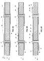
- FIGS. 1A-1Dillustrate various cross-sectional views of fabrication of a substrate precursor structure bearing a layer of conductive material using methods of the present invention
- FIGS. 2A-2Dillustrate various cross-sectional views of the substrate precursor structure of FIG. 1D being further processed into a finished substrate using a first process sequence of the present invention
- FIGS. 3A-3Eillustrate various cross-sectional views of the substrate precursor structure of FIG. 1D being further processed into a finished substrate using a second process sequence of the present invention
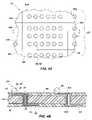
- FIG. 4Ais a top view of a plurality of substrates that may be fabricated at the wafer level using the methods of the present invention.
- FIG. 4Bis a partial cross-section of a portion of the plurality of substrates of FIG. 4A .
- the present inventionincludes methods of fabricating interposers and other substrates for use in chip-scale packaging, wafer-level packaging, other types of semiconductor device assembly and packaging and semiconductor device testing, as well as interposers and other substrates that may be fabricated by such methods. While the present invention is described in terms of certain specific, exemplary embodiments, the specific details of these embodiments are set forth in order to provide a thorough understanding of the present invention. It will be apparent, however, that the present invention may be practiced in various combinations of the specific exemplary embodiments presented herein.
- wafer and substrateare understood to include any substrate structure, including nonwafer bulk semiconductor substrates and partial wafers having a surface on which an insulating layer or a conductive layer may be formed, as well as substrates formed from materials other than semiconductors.
- substrate precursor structureis further used to refer to wafers and other substrates during processing, and may include material layers that have been fabricated thereupon. Wafers, substrates and substrate precursor structures may include doped and undoped semiconductor material, epitaxial semiconductor layers supported by a base semiconductor, as well as other semiconductor structures known to those of ordinary skill in the art.
- conductoris understood to include semiconductors, and the terms “insulator” and “dielectric” include any material that is less electrically conductive than the materials referred to as conductors.
- conductive elementis understood to include contacts to active regions of individual semiconductor devices as well as contacts to other regions on or within a wafer or other substrate. “Conductive element” is also meant to include metal pads, lines, traces, layers, conductive via walls or fillings, combinations thereof and similar conductive regions that may be used to connect individual active devices within an integrated circuit, to connect an integrated circuit and another electronic component to be associated therewith, or to connect between locations on a substrate.
- the present inventionprovides methods for fabricating substrates such as interposers for use in various semiconductor device packaging strategies, including, but not limited to, wafer-level packages and ball grid array packages.
- substratessuch as interposers for use in various semiconductor device packaging strategies, including, but not limited to, wafer-level packages and ball grid array packages.
- the methods described hereinprovide efficient and cost effective measures for providing substrates of high quality that are less expensive and time-consuming to manufacture than may be conventionally fabricated.
- FIGS. 1A-1Dthere is shown various cross-sectional views of acts involved in fabricating a substrate, such as an interposer, depicting preliminary elements of a method of fabricating the substrate.
- FIG. 1Athere is shown a cross-sectional view of a substrate blank 10 of the substrate.
- the substrateincludes a substantially planar substrate blank 10 that may be formed from a semiconductor material, such as silicon, gallium arsenide, or indium phosphide, a ceramic, a plastic or resin, a glass such as a photoetchable glass, or a so-called silicon-on-insulator (“SOI”) substrate (e.g., silicon-on-glass (“SOG”), silicon-on-ceramic (“SOC”), silicon-on-sapphire (“SOS”), etc.).
- SOIsilicon-on-insulator
- SOIsilicon-on-insulator
- SOIsilicon-on-insulator
- SOIsilicon-on-insulator
- SOIsilicon-on-insulator
- SOIsilicon-on-insulator
- SOIsilicon-on-insulator
- SOIsilicon-on-insulator
- SOIsilicon-on-insulator
- SOIsilicon-on-insulator
- SOIsilicon-on-insulator
- SOIsilicon-on-insulator
- SOIsilicon-on-insulator
- FIG. 1Bthere is shown a cross-sectional view of the substrate blank 10 after apertures 12 have been created therein.
- the apertures 12may be created using known techniques, such as laser machining or ablation processes, which are also referred to as laser drilling techniques.
- Other known aperture formation processessuch as masking and anisotropic etching and mechanical drilling, are also encompassed by the present invention and may be employed as suitable for use with the material selected for substrate blank 10 .
- a collimated, high-intensity ultraviolet (UV) light beammay be used to selectively impinge on substrate blank 10 to form the apertures 12 or the substrate blank 10 may be masked except at aperture locations and the apertures 12 etched using a UV flood light.
- UVhigh-intensity ultraviolet
- Registration for placement of the apertures 12 in the substrate blank 10 at the selected locationsmay be accomplished by marking the substrate blank 10 with fiducial marks (not shown), as known in the art.
- the fiducial marksmay be detected by known processes, such as by using scanning projection aligners that function to position the substrate blank 10 for an accurate placement of the apertures 12 .
- the apertures 12extend through the substrate blank 10 , but it will be appreciated that some or all of the apertures 12 may not extend through the substrate blank 10 . Electroless deposition may result in effective step coverage in such so-called “blind” vias if the distribution of activating ions in the solution is uniform and deposition is somewhat slow.
- FIG. 1Cthere is shown a cross-sectional view of the substrate blank 10 after an insulative or dielectric layer 14 has been formed or deposited on substantially an entire exposed surface 11 thereof or at least on the regions of exposed surface 11 that are to have conductive structures disposed thereover.
- the term “entire exposed surface”will be used to refer to every exposed surface 11 of the substrate blank 10 , including the surfaces of any material layers that were previously formed on the substrate blank 10 , and surfaces 13 of the apertures 12 extending through the substrate.
- insulative or dielectric layer 14functions to electrically insulate exposed surfaces 11 of the substrate blank 10 and apertures 12 from conductive elements that are to be subsequently formed on the substrate blank 10
- insulative or dielectric layer 14is useful on substrate blanks 10 formed from semiconductive or conductive materials, as well as for improving the adherence of subsequently formed layers to the substrate. Accordingly, insulative or dielectric layer 14 may not be necessary on substrate blanks 10 that are formed from dielectric materials (e.g., substrate blanks 10 formed from glasses, certain ceramics, resins, other polymers, etc.).
- the insulative or dielectric layer 14may be formed in situ by known techniques (e.g., silicon dioxide) or by applying other insulative materials (e.g., polymeric insulating materials including polyimides and PARYLENETM polymers, silicon nitride, silicon oxynitride, and glasses such as borosilicate glass (BSG), phosphosilicate glass (PSG), and borophosphosilicate glass (BPSG)).
- BSGborosilicate glass
- PSGphosphosilicate glass
- BPSGborophosphosilicate glass
- an insulative or dielectric layer 14 of silicon dioxidemay be grown onto the exposed surfaces 11 of a substrate blank 10 that comprises silicon.
- the insulative or dielectric layer 14may be deposited on the substrate blank 10 using known techniques, such as chemical vapor deposition (“CVD”), including low-pressure chemical vapor deposition (LPCVD) and plasma-enhanced chemical vapor deposition (PECVD), as appropriate, for deposition of tetraethylorthosilicate (“TEOS”), silicon nitride, or silicon oxynitride, a spin-on process (e.g., spin-on-glass (“SOG”) or a spin-on polyimide coating) or a PARYLENETM process wherein a dimer is vaporized to a monomer and then exposed at lower temperatures to a surface to deposit a tenacious polymer thereon.
- An exemplary dimer used in the PARYLENETM processis di-para-xylene.
- the insulative or dielectric layer 14may overlie substantially the entire exposed surface 11 of the substrate blank 10 , including the surfaces 13 of the apertures 12 .
- a conductive base layer 16is applied over substantially all of the exposed regions of the surface of the insulative or dielectric layer 14 that overlie the substrate blank 10 .
- the conductive base layer 16may have a substantially uniform thickness and be applied substantially simultaneously to substantially all of the exposed surfaces of the insulative or dielectric layer 14 (i.e., without requiring reorientation, such as inversion, of the substrate blank 10 ).
- the exposed surface of insulative or dielectric layer 14may be roughened, as known in the art, to enhance the adhesion of the conductive base layer 16 to the insulative or dielectric layer 14 .
- the conductive base layer 16covers the entire surface of the insulative or dielectric layer 14 , including regions of the insulative or dielectric layer 14 that are located within each aperture 12 .
- a substrate of a dielectric materialmay not require an insulative or dielectric layer 14 and conductive base layer 16 may, therefore, be formed directly on exposed regions of the exposed surface 11 of the substrate blank 10 . Regions of the exposed surface 11 of such a dielectric substrate blank 10 to which conductive material is to be directly applied may be mechanically or chemically roughened prior to application of conductive material thereto.
- the conductive base layer 16may be deposited using electroless metal plating, wherein the substrate blank 10 is placed in an electroless plating bath, such that metal is chemically deposited to form the conductive base layer 16 .
- electroless plating of metalsis an economical method of depositing metal when compared to other metal deposition processes known to those of ordinary skill in the art.
- coppermay be deposited to form the conductive base layer 16 , resulting in a substrate precursor structure 2 ( FIG. 1D ).
- the term “electroless plating”will be used to refer to autocatalytic plating processes by which metal is deposited onto an object without the passage of electric current.
- Electroless plating baths and solutionsare well known in the art and are available commercially from companies such as Shipley Ronal, with headquarters in Marlborough, Mass., or Packaging Technologies, with headquarters in Santa Clara, Calif. Electroless plating processes bathe all parts of the object to be coated in a constant concentration of metal ions and, thus, deposit metal in a substantially even thickness over edges, corners, and into holes (such as apertures 12 ) of an object.
- One exemplary metal which may be electrolessly depositedis copper.
- nickel, cobalt and copper alloyed with magnesium or other metalscobalt, silver, iridium, gold, tungsten, molybdenum, platinum, palladium, nickel-phosphorus (NiP), palladium-phosphorus (Pd—P), cobalt-phosphorus (Co—P), a Co—W—P alloy, other alloys of the foregoing metals and mixtures thereof may alternatively be electrolessly deposited to form the conductive base layer 16 .
- a seed layer(not shown) of a conductive material is deposited over the surfaces of the substrate blank 10 and the inner surface 13 of apertures 12 .
- the seed layermay comprise titanium nitride (TiN), titanium (Ti), silicon nitride (Si 3 N 4 ), a polysilicon, tantalum nitride (TaN), or copper.
- Deposition processes that may be used to deposit the seed layerinclude CVD, PVD (sputtering), atomic layer deposition (ALD), PECVD, and vacuum evaporation. It will be apparent that the selection of the type of material and deposition process utilized to deposit the seed layer will vary depending on the type of material used to form the conductive base layer 16 .
- the seed layeris then coated with a conductive base layer 16 of metal using an electroless deposition process.
- the conductive base layer 16is deposited on the seed layer and, thus, over all surfaces of substrate blank 10 bearing the seed layer.
- an annular conductive pathis created through the apertures 12 .
- the electroless plating processforms a substantially conformal coating in the apertures 12 that is substantially free of any voids or keyholes.
- the conductive base layer 16 formed from the electroless plating processwill typically have a uniform thickness and a low porosity, will provide corrosion protection and will be relatively hard.
- the electroless plating processis accomplished by placing the substrate blank 10 into a bath containing an aqueous solution of the metal to be deposited in ionic form.
- the aqueous solutionalso includes a chemical reducing agent such that the metal may be deposited without the use of electrical energy.
- the driving force for the reduction of the metal ions and subsequent deposition in the electroless plating processis driven by the chemical reducing agent.
- the reduction reactionis essentially constant at all points on the seed layer so long as the aqueous solution is sufficiently agitated (for example, by ultrasound) to ensure that a uniform concentration of metal ions and reducing agents is distributed in the aqueous solution.
- the conductive base layer 16may be deposited using an electrolytic plating process.
- the substrate blank 10is placed in an electrolytic plating bath and an electrical current is passed through the bath between an anode and the substrate blank 10 , which serves as a cathode.
- the currentcauses the metal in the bath to be deposited over a conductive seed layer deposited on the substrate blank 10 (e.g., directly on the exposed surface 11 thereof or on the insulative or dielectric layer 14 overlying the substrate blank 10 ).
- tin-lead alloyin addition to copper and nickel, including, but not limited to, tin-lead alloy, tin, gold, palladium-nickel alloy, brass, bronze, cadmium, chromium, iron, lead, zinc, and rhodium, may be deposited as the conductive base layer 16 using the electrolytic process. Electroless or electrolytic plating processes may be used to form the conductive base layer 16 on substantially all of the exposed surfaces 11 of the substrate precursor structure 2 substantially simultaneously and with a substantially uniform thickness.
- sputteringmay also be used, as known to those of ordinary skill in the art, to form the conductive base layer 16 with other metals such as, for example, aluminum.
- conductively doped polysiliconmay be used as the conductive base layer 16 and deposited by methods well known in the art, such as by depositing a polysilicon layer using chemical vapor deposition (CVD).
- CVDchemical vapor deposition
- a conductive base layer 16may also be used to deposit various conductive materials, including electrically conductive metals to form the conductive base layer 16 , as known in the art.
- PVDphysical vapor deposition
- CVDchemical vapor deposition
- a substantially uniform thickness of conductive base layer 16may be difficult to achieve using electrolytic plating techniques, which may substantially increase the cost of plating due to anode cost.
- FIGS. 2A-2Dthere are shown various cross-sections of the substrate precursor structure 2 being further processed using an electroless plating process to form a substrate.
- a mask 18is formed over portions of the conductive base layer 16 on the substrate precursor structure 2 .
- the mask 18may comprise a so-called “photomask,” which has been formed by a selectively exposed (patterned) and developed photoresist material which may be, as desired, either a positive or negative photoresist.
- Openings 19 in the mask 18expose regions, or unmasked portions, of the conductive base layer 16 to be removed by etching processes, as known in the art, to define conductive elements in the form of traces, terminal pads, and the like on one or both opposing surfaces of substrate blank 10 .
- the apertures 12may be used to align the substrate precursor structure 2 for patterning of the mask 18 on both surfaces of the substrate precursor structure 2 . Such alignment may be used for the conventional, large lithography techniques used to pattern the mask 18 because the feature size of the conductive elements to be formed is fairly large and, therefore, submicron accuracy is not necessary. As previously described herein, the apertures 12 may be positioned on the substrate precursor structure 2 such that the position of the apertures 12 in relation to each other and in relation to other features on the substrate precursor structure 2 , such as the peripheral edges thereof, is known.
- the apertures 12may be used together (e.g., two, three or more of the apertures 12 ) and, optionally, in conjunction with fiducial marks (not shown) on the substrate precursor structure 2 for more accurate positioning of the substrate precursor structure 2 for X, Y and theta (rotational) alignment for patterning of the mask 18 .
- fiducial marksin at least two locations may be used for X, Y and theta alignment or a hole and a fiducial mark in close proximity may be employed.
- the fiducial marks and/or the apertures 12may be optically scanned, such as by known machine vision systems, to effect appropriate relative positioning of the mask pattern with substrate precursor structure 2 .
- features of the substrate precursor structure 2may be used to effect appropriate alignment thereof with the mask pattern.
- features of the substrate precursor structure 2may be used with mechanical contact aligners, such as three pins, one spring loaded, to secure the substrate precursor structure 2 in position.
- etchantif conductive base layer 16 comprises copper, may be nitric acid.
- etchants that selectively etch copperinclude, for example, acid cupric chloride, ferric chloride or persulfate.
- an etchant desirable for etching conductive base layer 16may undesirably strip the photoresist material of mask 18 .
- the mask 18may comprise a hard mask such as, for example, oxide or a plating mask, wherein the hard mask or the plating mask is resistant to a harsh etchant such as, for example, nitric acid.
- the portions of conductive base layer 16 remaining after etchingdefine the locations of conductive elements in the form of contact pads 26 , conductive traces 23 , and conductive via walls 24 .
- the mask 18is also used to mask the conductive base layer 16 comprising conductive via walls 24 within the apertures 12 and, thus, preserves those portions of the conductive base layer 16 within the aperture 12 .
- the mask 18may be removed using a known photoresist stripping process or other mask-removal process suitable for the type of mask 18 employed, as is known in the art. Timing of the removal of mask 18 will be dependent upon whether electrolytic or electroless plating is used to apply additional conductive materials.
- a conductive barrier layer 20may be formed over the conductive elements on substrate precursor structure 2 as shown in FIG. 2C .
- the conductive barrier layer 20may, by way of example only, be formed using an electroless plating process.
- the conductive barrier layer 20is nickel, but it will be appreciated by those of ordinary skill in the art that other barrier-type materials may be used, such as tantalum nitride, tantalum silicon nitride, titanium nitride, titanium silicon nitride, tungsten nitride, tungsten silicon nitride, tantalum carbide, cobalt tungsten, and molybdenum nitride, within the scope of the present invention.
- the conductive barrier layer 20is deposited by placing the substrate precursor structure 2 in an electroless nickel plating bath. It will be apparent to those of ordinary skill in the art that deposition of the conductive barrier layer 20 may be desirable, or not, depending on the type of material used for the conductive base layer 16 .
- a copper oxidemay otherwise form on the bare copper of conductive base layer 16 .
- nickelmay be used to coat the copper to prevent the formation of the copper oxides since wire bonds, solder balls, and other conductive structures do not adhere well to copper oxides.
- the conductive barrier layer 20such as nickel, is therefore deposited to facilitate securing of conductive structures to desired locations on the conductive base layer 16 .
- the conductive barrier layer 20may be eliminated.
- the conductive barrier layer 20is formed after the conductive base layer 16 is patterned, plates only onto the copper of the conductive elements, and so does not contact the insulative or dielectric layer 14 .
- conductive base layer 16is formed of palladium or platinum, alone or in conjunction with gold, no nickel barrier layer is required.
- conductive base layer 16comprises silver
- a conductive barrier layer 20such as nickel
- an aluminum conductive base layer 16may benefit from a conductive barrier layer 20 (e.g., nickel).
- wire bondsare to be attached to a contact pad 26 , it would be desirable to leave an aluminum conductive base layer 16 exposed.
- a noble metal conductive cap layer 22may be formed over the conductive elements of the substrate precursor structure 2 following the formation of the conductive base layer 16 with, if included, the formation of the conductive barrier layer 20 .
- the noble metal conductive cap layer 22comprises gold and is deposited using an electroless gold plating bath, as is known in the art. As illustrated in FIG. 2D , the noble metal conductive cap layer 22 overlies the conductive barrier layer 20 on the conductive elements of substrate precursor structure 2 , including within the aperture 12 . Once the gold noble metal conductive cap layer 22 has been deposited, formation of conductive elements in the form of contact pads 26 , conductive traces 23 , and conductive via walls 24 of the substrate precursor structure 2 is completed, producing substrate 1 .
- noble metal conductive cap layer 22Other metals that may be used to form the noble metal conductive cap layer 22 include, but are not limited to, palladium, platinum, silver, or alloys thereof. It will be appreciated that the different types of metals used for the noble metal conductive cap layer 22 , the conductive barrier layer 20 , and the conductive base layer 16 may vary and determine what other types of metals may be used in the associated layers.
- the conductive base layer 16is copper
- the conductive barrier layer 20is nickel
- the noble metal conductive cap layer 22is gold. Accordingly, the selection of which metals to use in each of the conductive base layer 16 , the conductive barrier layer 20 and the noble metal conductive cap layer 22 may vary depending on the characteristics and mutual compatibility of the various metals. It will be apparent to those of ordinary skill in the art that the conductive via walls 24 of conductive via 30 ( FIG. 2D ) and corresponding conductive traces 23 may be used to electrically mutually connect corresponding contact pads 26 or other components on opposing surfaces 27 , 28 of the substrate precursor structure 2 .
- One or both of the conductive barrier layer 20 and the noble metal conductive cap layer 22may have a substantially uniform thickness and be sequentially formed by electroless plating on the conductive base layer 16 substantially simultaneously over portions of opposing surfaces 27 , 28 of the substrate precursor structure 2 and within apertures 12 .
- additional layers 20 , 22 of conductive materialare preferably formed following the patterning of conductive base layer 16 but may, instead, be formed by blanket deposition over opposing surfaces 27 , 28 and within apertures 12 prior to patterning for formation of conductive elements in the form of contact pads 26 , conductive traces 23 , and conductive via walls 24 .
- FIGS. 3A-3Ethere are shown cross-sections through another substrate precursor structure 2 ′ at various levels of another exemplary process for fabricating a substrate 1 ′, such as an interposer, therefrom.
- an insulative or dielectric layer 14may be formed on at least a portion of the exposed surfaces 11 of the substrate blank 10 .
- FIG. 3Ashows a substrate precursor structure 2 ′ after a conductive base layer 16 has been formed on an insulative or dielectric layer 14 that has been formed on the substrate blank 10 , as described herein with reference to FIGS. 1A-1D .
- the conductive base layer 16is formed substantially simultaneously on opposing surfaces 27 , 28 of the substrate precursor structure 2 ′, as well as on the surfaces thereof that define apertures 12 therethrough. All of the regions of the conductive base layer 16 may have substantially uniform thicknesses. Formation of the conductive base layer 16 by an electrolytic plating process may be effected substantially simultaneously on all exposed surfaces of the substrate blank 10 and impart the conductive base layer 16 with a substantially uniform thickness.
- the conductive base layer 16may include copper.
- a mask 18 ′ of photoresist material similar to that of mask 18 depicted and described with respect to FIG. 2Amay be deposited, exposed to pattern the photoresist material, and developed to define the locations of conductive elements on substrate blank 10 .
- FIGS. 3A-3Ediffers from that described in reference to FIGS. 2A-2D by the manner in which a mask 18 ′ is used.
- the mask 18 ′is formed or positioned on portions of the conductive base layer 16 that are not to have a conductive barrier layer 20 ′ formed thereon.
- the mask 18 ′does not cover the interior of the aperture 12 or regions on the opposing surfaces 27 , 28 of the substrate precursor structure 2 ′ upon which conductive traces 23 , conductive via walls 24 , and contact pads 26 , that are covered by the subsequently formed conductive barrier layer 20 ′, are to be located.
- the conductive barrier layer 20 ′may be deposited by any suitable process. Portions of the conductive barrier layer 20 ′ that overlie exposed portions of conductive base layer 16 on each opposing surface 27 , 28 of the substrate precursor structure 2 ′ as well as on the interior surfaces 13 of the substrate precursor structure 2 ′ that are located within apertures 12 may be formed at substantially the same time by electrolytic plating. As with conductive base layer 16 , the conductive barrier layer 20 ′ may have a substantially uniform thickness.
- nickelmay be used to form the conductive barrier layer 20 ′.
- the conductive barrier layer 20 ′is deposited by placing the substrate precursor structure 2 ′ in a suitable electrolytic plating bath. In the case of an electrolytic plating bath, an electric current is passed through the bath such that the nickel is deposited on exposed areas of the conductive base layer 16 serving as a cathode on the substrate precursor structure 2 ′, including those within the apertures 12 .
- the mask 18 ′may be removed from the substrate precursor structure 2 ′ using a conventional resist strip process for removing photomasks, or any other suitable mask removal method known in the art, as shown in FIG. 3D .
- the conductive base layer 16may be patterned using the conductive barrier layer 20 ′ as a mask and an etchant which is selective for the material of the conductive base layer 16 over that of the conductive barrier layer 20 ′ (e.g., nitric acid, acid cupric chloride, ferric chloride and persulfate selectively etch copper).
- a noble metal conductive cap layer 22 ′may be deposited on the conductive barrier layer 20 ′. All portions of the noble metal conductive cap layer 22 ′ (i.e., portions thereof over opposing surfaces 27 , 28 of the substrate precursor structure 2 ′, as well as portions thereof within apertures 12 ) may be substantially simultaneously formed to exhibit a substantially uniform thickness.
- a deposition process which selectively deposits material onto metalsuch as the electroless plating methods previously described herein with reference to FIG. 2D , may be used to form the noble metal conductive cap layer 22 ′.
- metalsuch as the electroless plating methods previously described herein with reference to FIG. 2D
- goldmay be used to form the noble metal conductive cap layer 22 ′ but, as previously described herein, other metals may also be used to form the noble metal conductive cap layer 22 ′.
- a substrate 1 , 1 ′ produced using the methods of the present inventionmay be further configured with contact pads 26 ′, fabricated in respective communication with corresponding electrically conductive via 30 , 30 ′ through conductive traces 23 , 23 ′. It will be appreciated that the contact pads 26 , 26 ′ may be used for outer lead bonding sites for subsequent placement of discrete conductive elements such as solder balls or conductive or conductor-filled epoxy bumps, studs, columns or pillars.
- a patterned protection layer of dielectric materialsuch as a layer 60 of polymer shown in broken lines in FIGS.
- 2D and 3Emay also be formed and patterned on opposing surfaces 27 , 28 of the substrate precursor structure 2 , 2 ′ to expose contact pads 26 , 26 ′ and used as a solder barrier to contain solder during reflow used to form conductive solder balls thereon or during connection of substrate 1 , 1 ′ to, for example, a flip-chip configured semiconductor die having solder balls thereon.
- FIGS. 4A and 4Bthere is shown a large substrate, such as a waler-scale substrate generally at 41 , that may be used to simultaneously fabricate a large plurality of interposers or other substrates 40 a - 40 i (collectively referred to herein as “substrates 40 ”) using the methods of the present invention.
- substrates 40such as a waler-scale substrate generally at 41
- FIG. 4Ashown is a top view of the large substrate 41 depicting the several substrates 40 a - 40 i .
- FIG. 4Billustrates a partial cross-section of a single substrate 40 e along line 1 - 1 of FIG. 4A , which includes a substantially planar substrate blank 10 ′′, which may be formed from an electrically nonconductive material, such as glass, a ceramic, a resin or a polymer, or an at least partially insulator-coated semiconductive or conductive material. As depicted in FIG.
- the substrates 40 a - 40 imay be simultaneously fabricated on a single, large substrate 41 such as a full or partial wafer of silicon, germanium, gallium arsenide or indium phosphide, or another bulk semiconductor substrate, such as a so-called silicon-on-insulator (“SOI”) substrate in the form of a silicon-on-ceramic (“SOC”), silicon-on-glass (“SOG”), or silicon-on-sapphire (“SOS”) substrate.
- SOIsilicon-on-insulator
- SOCsilicon-on-ceramic
- SOOGsilicon-on-glass
- SOSsilicon-on-sapphire
- Each resulting substrate 40may include a plurality of conductive traces 23 extending from conductive vias 30 to contact pads 26 .
- a top 25 t and/or a bottom 25 b of each conductive via 30is substantially level with an associated conductive trace 23 and contact pad 26 on a top surface 44 and a bottom surface 46 of the substrate 40 e .
- a protective, dielectric polymer layer 60extends over top surface 44 and bottom surface 46 , with apertures 62 (see also FIGS. 2D and 3E ) therethrough providing locations for conductive structures 52 such as solder balls or locations for access by test probes.
- the protective layer 60may exhibit a relatively planar surface across top surface 44 and bottom surface 46 , rather than being conformal to the topography of the traces 23 as depicted in FIGS. 2D and 3E .
- the substrates 40may be fabricated with the various insulative or dielectric layers 14 , conductive base layers 16 , conductive barrier layers 20 , 20 ′ and noble metal conductive cap layers 22 , 22 ′ (see FIGS. 2A-3E ), as previously described herein, such that the substrates 40 are configured for the subsequent placement of circuit elements thereon or therein.
- contact pads 26 and conductive traces 23may be fabricated on both the top and bottom surfaces 44 and 46 of the substrate 40 for connection to various circuit elements and other conductive elements as previously described herein.
- Conductive structures 52may be placed in communication with conductive vias 30 or contact pads 26 of the substrate 40 or another carrier substrate, as known in the art.
- Conductive structures 52that may be used include, but are not limited to, bumps, balls, studs, columns or pillars of any suitable conductive material, such as solder, another metal or metal alloy, conductive or conductor-filled epoxy, a conductive elastomer such as an anisotropically conductive film, or the like.
- the substrate 40 described hereinmay be configured as an interposer or other carrier substrate and have a semiconductor device (not shown) secured adjacent to the top surface 44 thereof.
- the bottom surface 46 of the substrate 40may be assembled with a test structure (not shown).
- the substrate 40 described hereinmay be further processed for subsequent use in packaging structures, such as a ball grid array (BGA) package.
- a protective layer 60 of a polymer materialmay be formed on the top and bottom surfaces 44 and 46 of the substrate 40 and around contact pads 26 to provide a solder barrier.
Landscapes
- Engineering & Computer Science (AREA)
- Microelectronics & Electronic Packaging (AREA)
- Physics & Mathematics (AREA)
- Condensed Matter Physics & Semiconductors (AREA)
- General Physics & Mathematics (AREA)
- Computer Hardware Design (AREA)
- Power Engineering (AREA)
- Ceramic Engineering (AREA)
- Manufacturing & Machinery (AREA)
- Chemical & Material Sciences (AREA)
- Internal Circuitry In Semiconductor Integrated Circuit Devices (AREA)
Abstract
Description
Claims (16)
Priority Applications (1)
| Application Number | Priority Date | Filing Date | Title |
|---|---|---|---|
| US11/717,946US7603772B2 (en) | 2004-01-12 | 2007-03-13 | Methods of fabricating substrates including one or more conductive vias |
Applications Claiming Priority (2)
| Application Number | Priority Date | Filing Date | Title |
|---|---|---|---|
| US10/755,905US7316063B2 (en) | 2004-01-12 | 2004-01-12 | Methods of fabricating substrates including at least one conductive via |
| US11/717,946US7603772B2 (en) | 2004-01-12 | 2007-03-13 | Methods of fabricating substrates including one or more conductive vias |
Related Parent Applications (1)
| Application Number | Title | Priority Date | Filing Date |
|---|---|---|---|
| US10/755,905DivisionUS7316063B2 (en) | 2004-01-12 | 2004-01-12 | Methods of fabricating substrates including at least one conductive via |
Publications (2)
| Publication Number | Publication Date |
|---|---|
| US20070169343A1 US20070169343A1 (en) | 2007-07-26 |
| US7603772B2true US7603772B2 (en) | 2009-10-20 |
Family
ID=34739698
Family Applications (4)
| Application Number | Title | Priority Date | Filing Date |
|---|---|---|---|
| US10/755,905Expired - LifetimeUS7316063B2 (en) | 2004-01-12 | 2004-01-12 | Methods of fabricating substrates including at least one conductive via |
| US11/484,962AbandonedUS20060254808A1 (en) | 2004-01-12 | 2006-07-12 | Substrate precursor structures |
| US11/717,946Expired - LifetimeUS7603772B2 (en) | 2004-01-12 | 2007-03-13 | Methods of fabricating substrates including one or more conductive vias |
| US11/941,358Expired - LifetimeUS7594322B2 (en) | 2004-01-12 | 2007-11-16 | Methods of fabricating substrates including at least one conductive via |
Family Applications Before (2)
| Application Number | Title | Priority Date | Filing Date |
|---|---|---|---|
| US10/755,905Expired - LifetimeUS7316063B2 (en) | 2004-01-12 | 2004-01-12 | Methods of fabricating substrates including at least one conductive via |
| US11/484,962AbandonedUS20060254808A1 (en) | 2004-01-12 | 2006-07-12 | Substrate precursor structures |
Family Applications After (1)
| Application Number | Title | Priority Date | Filing Date |
|---|---|---|---|
| US11/941,358Expired - LifetimeUS7594322B2 (en) | 2004-01-12 | 2007-11-16 | Methods of fabricating substrates including at least one conductive via |
Country Status (1)
| Country | Link |
|---|---|
| US (4) | US7316063B2 (en) |
Cited By (25)
| Publication number | Priority date | Publication date | Assignee | Title |
|---|---|---|---|---|
| US20090049688A1 (en)* | 2005-09-08 | 2009-02-26 | International Business Machines Corporation | Land grid array (lga) interposer utilizing metal-on-elastomer hemi-torus and other multiple points of contact geometries |
| US20090085180A1 (en)* | 2007-09-29 | 2009-04-02 | Kinik Company | Packaging carrier with high heat dissipation and method for manufacturing the same |
| US20090094825A1 (en)* | 2007-10-12 | 2009-04-16 | Fujitsu Limited | Method of producing substrate |
| US20090094824A1 (en)* | 2007-10-12 | 2009-04-16 | Fujitsu Limited | Method of producing substrate |
| US20090152708A1 (en)* | 2007-12-13 | 2009-06-18 | Woong Sun Lee | Substrate for high speed semiconductor package and semiconductor package having the same |
| US20110195360A1 (en)* | 2010-02-10 | 2011-08-11 | Life Bioscience, Inc. | Methods to fabricate a photoactive substrate suitable for microfabrication |
| US20110217657A1 (en)* | 2010-02-10 | 2011-09-08 | Life Bioscience, Inc. | Methods to fabricate a photoactive substrate suitable for microfabrication |
| US8148263B2 (en) | 2003-09-23 | 2012-04-03 | Micron Technology, Inc. | Methods for forming conductive vias in semiconductor device components |
| US20120261832A1 (en)* | 2011-04-18 | 2012-10-18 | Taiyo Yuden Co., Ltd. | Wiring Board, Semiconductor Device, and Method for Manufacturing Wiring Board |
| US10070533B2 (en) | 2015-09-30 | 2018-09-04 | 3D Glass Solutions, Inc. | Photo-definable glass with integrated electronics and ground plane |
| US10665377B2 (en) | 2014-05-05 | 2020-05-26 | 3D Glass Solutions, Inc. | 2D and 3D inductors antenna and transformers fabricating photoactive substrates |
| US10854946B2 (en) | 2017-12-15 | 2020-12-01 | 3D Glass Solutions, Inc. | Coupled transmission line resonate RF filter |
| US10903545B2 (en) | 2018-05-29 | 2021-01-26 | 3D Glass Solutions, Inc. | Method of making a mechanically stabilized radio frequency transmission line device |
| US11076489B2 (en) | 2018-04-10 | 2021-07-27 | 3D Glass Solutions, Inc. | RF integrated power condition capacitor |
| US11101532B2 (en) | 2017-04-28 | 2021-08-24 | 3D Glass Solutions, Inc. | RF circulator |
| US11139582B2 (en) | 2018-09-17 | 2021-10-05 | 3D Glass Solutions, Inc. | High efficiency compact slotted antenna with a ground plane |
| US11161773B2 (en) | 2016-04-08 | 2021-11-02 | 3D Glass Solutions, Inc. | Methods of fabricating photosensitive substrates suitable for optical coupler |
| US11264167B2 (en) | 2016-02-25 | 2022-03-01 | 3D Glass Solutions, Inc. | 3D capacitor and capacitor array fabricating photoactive substrates |
| US11270843B2 (en) | 2018-12-28 | 2022-03-08 | 3D Glass Solutions, Inc. | Annular capacitor RF, microwave and MM wave systems |
| US11342896B2 (en) | 2017-07-07 | 2022-05-24 | 3D Glass Solutions, Inc. | 2D and 3D RF lumped element devices for RF system in a package photoactive glass substrates |
| US11373908B2 (en) | 2019-04-18 | 2022-06-28 | 3D Glass Solutions, Inc. | High efficiency die dicing and release |
| US11594457B2 (en) | 2018-12-28 | 2023-02-28 | 3D Glass Solutions, Inc. | Heterogenous integration for RF, microwave and MM wave systems in photoactive glass substrates |
| US11677373B2 (en) | 2018-01-04 | 2023-06-13 | 3D Glass Solutions, Inc. | Impedence matching conductive structure for high efficiency RF circuits |
| US11962057B2 (en) | 2019-04-05 | 2024-04-16 | 3D Glass Solutions, Inc. | Glass based empty substrate integrated waveguide devices |
| US12165809B2 (en) | 2016-02-25 | 2024-12-10 | 3D Glass Solutions, Inc. | 3D capacitor and capacitor array fabricating photoactive substrates |
Families Citing this family (74)
| Publication number | Priority date | Publication date | Assignee | Title |
|---|---|---|---|---|
| US7091124B2 (en) | 2003-11-13 | 2006-08-15 | Micron Technology, Inc. | Methods for forming vias in microelectronic devices, and methods for packaging microelectronic devices |
| US8084866B2 (en) | 2003-12-10 | 2011-12-27 | Micron Technology, Inc. | Microelectronic devices and methods for filling vias in microelectronic devices |
| TWI255491B (en)* | 2004-03-31 | 2006-05-21 | Sanyo Electric Co | Substrate for mounting elements, manufacturing method therefor and semiconductor device using the same |
| US20050247894A1 (en) | 2004-05-05 | 2005-11-10 | Watkins Charles M | Systems and methods for forming apertures in microfeature workpieces |
| JP4430976B2 (en)* | 2004-05-10 | 2010-03-10 | 富士通株式会社 | Wiring board and manufacturing method thereof |
| US7232754B2 (en) | 2004-06-29 | 2007-06-19 | Micron Technology, Inc. | Microelectronic devices and methods for forming interconnects in microelectronic devices |
| SG120200A1 (en) | 2004-08-27 | 2006-03-28 | Micron Technology Inc | Slanted vias for electrical circuits on circuit boards and other substrates |
| US7300857B2 (en) | 2004-09-02 | 2007-11-27 | Micron Technology, Inc. | Through-wafer interconnects for photoimager and memory wafers |
| US7279407B2 (en) | 2004-09-02 | 2007-10-09 | Micron Technology, Inc. | Selective nickel plating of aluminum, copper, and tungsten structures |
| JP4564342B2 (en)* | 2004-11-24 | 2010-10-20 | 大日本印刷株式会社 | Multilayer wiring board and manufacturing method thereof |
| US7271482B2 (en) | 2004-12-30 | 2007-09-18 | Micron Technology, Inc. | Methods for forming interconnects in microelectronic workpieces and microelectronic workpieces formed using such methods |
| KR100946878B1 (en)* | 2005-01-10 | 2010-03-09 | 삼성전자주식회사 | Channel quality information channel allocation system and method in communication system |
| GB0501199D0 (en)* | 2005-01-21 | 2005-03-02 | Qinetiq Ltd | Improved RF tags |
| US7670951B2 (en)* | 2005-06-27 | 2010-03-02 | Intel Corporation | Grid array connection device and method |
| US20060290001A1 (en)* | 2005-06-28 | 2006-12-28 | Micron Technology, Inc. | Interconnect vias and associated methods of formation |
| US7795134B2 (en) | 2005-06-28 | 2010-09-14 | Micron Technology, Inc. | Conductive interconnect structures and formation methods using supercritical fluids |
| KR100688560B1 (en)* | 2005-07-22 | 2007-03-02 | 삼성전자주식회사 | Wafer level chip scale package and its manufacturing method |
| US7863187B2 (en) | 2005-09-01 | 2011-01-04 | Micron Technology, Inc. | Microfeature workpieces and methods for forming interconnects in microfeature workpieces |
| US7622377B2 (en)* | 2005-09-01 | 2009-11-24 | Micron Technology, Inc. | Microfeature workpiece substrates having through-substrate vias, and associated methods of formation |
| US7262134B2 (en) | 2005-09-01 | 2007-08-28 | Micron Technology, Inc. | Microfeature workpieces and methods for forming interconnects in microfeature workpieces |
| US7511228B2 (en)* | 2005-09-14 | 2009-03-31 | Schmartboard, Inc. | Printed circuit board |
| US7700438B2 (en)* | 2006-01-30 | 2010-04-20 | Freescale Semiconductor, Inc. | MOS device with nano-crystal gate structure |
| TWI305115B (en)* | 2006-04-14 | 2009-01-01 | Gigno Technology Co Ltd | Glass circuit board and manufacturing method thereof |
| US7552534B2 (en)* | 2006-05-11 | 2009-06-30 | Eastman Kodak Company | Method of manufacturing an integrated orifice plate and electroformed charge plate |
| US7749899B2 (en) | 2006-06-01 | 2010-07-06 | Micron Technology, Inc. | Microelectronic workpieces and methods and systems for forming interconnects in microelectronic workpieces |
| US7629249B2 (en) | 2006-08-28 | 2009-12-08 | Micron Technology, Inc. | Microfeature workpieces having conductive interconnect structures formed by chemically reactive processes, and associated systems and methods |
| US7902643B2 (en) | 2006-08-31 | 2011-03-08 | Micron Technology, Inc. | Microfeature workpieces having interconnects and conductive backplanes, and associated systems and methods |
| US20090084589A1 (en)* | 2007-01-22 | 2009-04-02 | Kunihiro Tan | Lead terminal bonding method and printed circuit board |
| US7812461B2 (en)* | 2007-03-27 | 2010-10-12 | Micron Technology, Inc. | Method and apparatus providing integrated circuit having redistribution layer with recessed connectors |
| KR100861619B1 (en)* | 2007-05-07 | 2008-10-07 | 삼성전기주식회사 | Thermal printed circuit board and its manufacturing method |
| SG149710A1 (en) | 2007-07-12 | 2009-02-27 | Micron Technology Inc | Interconnects for packaged semiconductor devices and methods for manufacturing such devices |
| TWI335059B (en)* | 2007-07-31 | 2010-12-21 | Siliconware Precision Industries Co Ltd | Multi-chip stack structure having silicon channel and method for fabricating the same |
| SG150410A1 (en)* | 2007-08-31 | 2009-03-30 | Micron Technology Inc | Partitioned through-layer via and associated systems and methods |
| US7999388B2 (en)* | 2007-09-24 | 2011-08-16 | Research Triangle Institute | Preventing breakage of long metal signal conductors on semiconductor substrates |
| US8077475B2 (en) | 2007-09-27 | 2011-12-13 | Infineon Technologies Ag | Electronic device |
| JP2009099589A (en)* | 2007-10-12 | 2009-05-07 | Elpida Memory Inc | Wafer or circuit board and connection structure thereof |
| JP4443598B2 (en)* | 2007-11-26 | 2010-03-31 | シャープ株式会社 | Double-sided wiring board |
| US7884015B2 (en) | 2007-12-06 | 2011-02-08 | Micron Technology, Inc. | Methods for forming interconnects in microelectronic workpieces and microelectronic workpieces formed using such methods |
| US8084854B2 (en) | 2007-12-28 | 2011-12-27 | Micron Technology, Inc. | Pass-through 3D interconnect for microelectronic dies and associated systems and methods |
| US20090260862A1 (en)* | 2008-04-16 | 2009-10-22 | Andrew Yaung | Circuit modification device for printed circuit boards |
| US8253230B2 (en) | 2008-05-15 | 2012-08-28 | Micron Technology, Inc. | Disabling electrical connections using pass-through 3D interconnects and associated systems and methods |
| US7745244B2 (en) | 2008-06-23 | 2010-06-29 | Fairchild Semiconductor Corporation | Pin substrate and package |
| WO2010021262A1 (en)* | 2008-08-19 | 2010-02-25 | 株式会社村田製作所 | Circuit module and method for manufacturing same |
| TWI407540B (en)* | 2008-10-02 | 2013-09-01 | 矽品精密工業股份有限公司 | Multi-chip stacked structure having through silicon via and fabrication method thereof |
| US8143532B2 (en)* | 2009-02-05 | 2012-03-27 | Xilinx, Inc. | Barrier layer to prevent conductive anodic filaments |
| US8168892B2 (en)* | 2009-02-23 | 2012-05-01 | Nokia Corporation | Soldermask-less printed wiring board |
| JP5150534B2 (en)* | 2009-03-06 | 2013-02-20 | 信越ポリマー株式会社 | Coverlay film, method for producing the same, and flexible printed wiring board |
| US8093151B2 (en)* | 2009-03-13 | 2012-01-10 | Stats Chippac, Ltd. | Semiconductor die and method of forming noise absorbing regions between THVS in peripheral region of the die |
| DE102009038674B4 (en)* | 2009-08-24 | 2012-02-09 | Epcos Ag | Carrier device, arrangement with such a carrier device and method for producing a structured layer stack comprising at least one ceramic layer |
| KR101106404B1 (en)* | 2009-11-24 | 2012-01-17 | 삼성에스디아이 주식회사 | Secondary Battery and Manufacturing Method Thereof |
| US8450619B2 (en)* | 2010-01-07 | 2013-05-28 | International Business Machines Corporation | Current spreading in organic substrates |
| KR20110092553A (en)* | 2010-02-09 | 2011-08-18 | 삼성전자주식회사 | Semiconductor package module including self-assembled insulating thin film and method of manufacturing the same |
| US20110204517A1 (en)* | 2010-02-23 | 2011-08-25 | Qualcomm Incorporated | Semiconductor Device with Vias Having More Than One Material |
| TWI442852B (en)* | 2012-07-02 | 2014-06-21 | Subtron Technology Co Ltd | Manufacturing method of substrate structure |
| US10115671B2 (en)* | 2012-08-03 | 2018-10-30 | Snaptrack, Inc. | Incorporation of passives and fine pitch through via for package on package |
| KR101932660B1 (en)* | 2012-09-12 | 2018-12-26 | 삼성전자 주식회사 | Integrated circuit device having through silicon via structure and method of manufacturing the same |
| SE538062C2 (en) | 2012-09-27 | 2016-02-23 | Silex Microsystems Ab | Chemically plated metal wire through silicon |
| US20140144681A1 (en)* | 2012-11-27 | 2014-05-29 | Qualcomm Mems Technologies, Inc. | Adhesive metal nitride on glass and related methods |
| US10913653B2 (en)* | 2013-03-07 | 2021-02-09 | MCube Inc. | Method of fabricating MEMS devices using plasma etching and device therefor |
| JP6235785B2 (en)* | 2013-03-18 | 2017-11-22 | 日本電子材料株式会社 | Probe card guide plate and probe card guide plate manufacturing method |
| JP6225047B2 (en)* | 2014-03-06 | 2017-11-01 | 名東電産株式会社 | Printed wiring board using aluminum as conductive pattern, and manufacturing method thereof |
| DE102014115815B4 (en) | 2014-10-30 | 2022-11-17 | Infineon Technologies Ag | METHOD FOR MANUFACTURING A CIRCUIT CARRIER, METHOD FOR MANUFACTURING A SEMICONDUCTOR DEVICE, METHOD FOR OPERATING A SEMICONDUCTOR DEVICE AND METHOD FOR MANUFACTURING A SEMICONDUCTOR MODULE |
| US20170013715A1 (en)* | 2015-07-10 | 2017-01-12 | Rohde & Schwarz Gmbh & Co. Kg | Printed circuit board and corresponding method for producing a printed circuit board |
| US10211071B2 (en)* | 2016-01-29 | 2019-02-19 | Nxp B.V. | IC packaging method and a packaged IC device |
| EP3226291B1 (en)* | 2016-04-01 | 2024-04-03 | Nichia Corporation | Method of manufacturing a light emitting element mounting base member, and light emitting element mounting base member |
| TWI645483B (en)* | 2017-06-30 | 2018-12-21 | 同泰電子科技股份有限公司 | Manufacturing method of substrate structure comprising vias |
| CN113366926A (en)* | 2019-01-29 | 2021-09-07 | 蝴蝶网络有限公司 | Packaging structure and packaging method for on-chip ultrasonic equipment |
| CN110071047B (en)* | 2019-04-28 | 2020-12-18 | 北京航天控制仪器研究所 | Method for manufacturing silicon-based adapter plate for micro-system integrated application |
| KR20220164800A (en) | 2020-04-17 | 2022-12-13 | 3디 글래스 솔루션즈 인코포레이티드 | broadband inductor |
| US12159844B2 (en) | 2020-09-23 | 2024-12-03 | Intel Corporation | Electronic substrates having embedded inductors |
| US12057252B2 (en)* | 2020-09-23 | 2024-08-06 | Intel Corporation | Electronic substrates having embedded inductors |
| US20230395445A1 (en)* | 2022-06-06 | 2023-12-07 | Intel Corporation | Glass core architectures with dielectric buffer layer between glass core and metal vias and pads |
| KR20240050065A (en)* | 2022-10-11 | 2024-04-18 | (주)포인트엔지니어링 | Guide plate and test device including the same |
| CN115500011B (en)* | 2022-11-03 | 2023-02-03 | 四川富乐华半导体科技有限公司 | Positioning method for DPC ceramic substrate processing |
Citations (80)
| Publication number | Priority date | Publication date | Assignee | Title |
|---|---|---|---|---|
| US2820752A (en) | 1954-02-04 | 1958-01-21 | Du Pont | Electrodeposition of tetrafluoroethylene polymers |
| US3577324A (en) | 1968-01-24 | 1971-05-04 | Sondell Research Dev Co | Process of coating particles with metals |
| US4179800A (en)* | 1975-10-20 | 1979-12-25 | Nippon Electric Company, Ltd. | Printed wiring board comprising a conductive pattern retreating at least partly in a through-hole |
| US4211603A (en)* | 1978-05-01 | 1980-07-08 | Tektronix, Inc. | Multilayer circuit board construction and method |
| US4312897A (en) | 1978-09-18 | 1982-01-26 | Hughes Aircraft Company | Buried resist technique for the fabrication of printed wiring |
| US4325780A (en)* | 1980-09-16 | 1982-04-20 | Schulz Sr Robert M | Method of making a printed circuit board |
| US4487654A (en)* | 1983-10-27 | 1984-12-11 | Ael Microtel Limited | Method of manufacturing printed wiring boards |
| US4525246A (en) | 1982-06-24 | 1985-06-25 | Hadco Corporation | Making solderable printed circuit boards |
| US4605471A (en) | 1985-06-27 | 1986-08-12 | Ncr Corporation | Method of manufacturing printed circuit boards |
| US4692349A (en) | 1986-03-03 | 1987-09-08 | American Telephone And Telegraph Company, At&T Bell Laboratories | Selective electroless plating of vias in VLSI devices |
| US4720324A (en)* | 1985-10-03 | 1988-01-19 | Hayward John S | Process for manufacturing printed circuit boards |
| US4808273A (en) | 1988-05-10 | 1989-02-28 | Avantek, Inc. | Method of forming completely metallized via holes in semiconductors |
| US4830264A (en) | 1986-10-08 | 1989-05-16 | International Business Machines Corporation | Method of forming solder terminals for a pinless ceramic module |
| US4954313A (en) | 1989-02-03 | 1990-09-04 | Amdahl Corporation | Method and apparatus for filling high density vias |
| US4978639A (en) | 1989-01-10 | 1990-12-18 | Avantek, Inc. | Method for the simultaneous formation of via-holes and wraparound plating on semiconductor chips |
| US5160579A (en)* | 1991-06-05 | 1992-11-03 | Macdermid, Incorporated | Process for manufacturing printed circuit employing selective provision of solderable coating |
| US5168624A (en)* | 1990-07-18 | 1992-12-08 | Nippon Cmk Corp. | Method of manufacturing printed wiring board |
| US5218761A (en)* | 1991-04-08 | 1993-06-15 | Nec Corporation | Process for manufacturing printed wiring boards |
| US5224265A (en) | 1991-10-29 | 1993-07-06 | International Business Machines Corporation | Fabrication of discrete thin film wiring structures |
| US5228966A (en) | 1991-01-31 | 1993-07-20 | Nec Corporation | Gilding apparatus for semiconductor substrate |
| US5245751A (en) | 1990-04-27 | 1993-09-21 | Circuit Components, Incorporated | Array connector |
| US5262718A (en) | 1985-08-05 | 1993-11-16 | Raychem Limited | Anisotropically electrically conductive article |
| US5285352A (en) | 1992-07-15 | 1994-02-08 | Motorola, Inc. | Pad array semiconductor device with thermal conductor and process for making the same |
| US5309632A (en)* | 1988-03-28 | 1994-05-10 | Hitachi Chemical Co., Ltd. | Process for producing printed wiring board |
| US5374788A (en) | 1992-10-09 | 1994-12-20 | International Business Machines Corporation | Printed wiring board and manufacturing method therefor |
| US5421083A (en) | 1994-04-01 | 1995-06-06 | Motorola, Inc. | Method of manufacturing a circuit carrying substrate having coaxial via holes |
| US5424245A (en) | 1994-01-04 | 1995-06-13 | Motorola, Inc. | Method of forming vias through two-sided substrate |
| US5536908A (en) | 1993-01-05 | 1996-07-16 | Schlumberger Technology Corporation | Lead-free printed circuit assembly |
| US5674787A (en) | 1996-01-16 | 1997-10-07 | Sematech, Inc. | Selective electroless copper deposited interconnect plugs for ULSI applications |
| US5682062A (en) | 1995-06-05 | 1997-10-28 | Harris Corporation | System for interconnecting stacked integrated circuits |
| US5689091A (en)* | 1996-09-19 | 1997-11-18 | Vlsi Technology, Inc. | Multi-layer substrate structure |
| US5853559A (en) | 1997-02-17 | 1998-12-29 | Mitsubishi Denki Kabushiki Kaisha | Apparatus for electroplating a semiconductor substrate |
| US5876580A (en) | 1996-01-12 | 1999-03-02 | Micromodule Systems | Rough electrical contact surface |
| EP0907206A1 (en) | 1997-10-01 | 1999-04-07 | Matsushita Electronics Corporation | Substrate through-contact and its fabrication method |
| US5897368A (en) | 1997-11-10 | 1999-04-27 | General Electric Company | Method of fabricating metallized vias with steep walls |
| JPH11251316A (en) | 1998-03-02 | 1999-09-17 | Toshiba Corp | Method for manufacturing multi-chip semiconductor device |
| US6027995A (en) | 1996-06-26 | 2000-02-22 | Intel Corporation | Method for fabricating an interconnect structure with hard mask and low dielectric constant materials |
| US6032527A (en) | 1998-07-01 | 2000-03-07 | Memsys, Inc. | Solid state microanemometer |
| US6072236A (en) | 1996-03-07 | 2000-06-06 | Micron Technology, Inc. | Micromachined chip scale package |
| US6114768A (en) | 1996-10-07 | 2000-09-05 | Intersil Corporation | Surface mount die by handle replacement |
| US6169024B1 (en) | 1998-09-30 | 2001-01-02 | Intel Corporation | Process to manufacture continuous metal interconnects |
| US6197664B1 (en) | 1999-01-12 | 2001-03-06 | Fujitsu Limited | Method for electroplating vias or through holes in substrates having conductors on both sides |
| US6228754B1 (en) | 1999-01-05 | 2001-05-08 | Advanced Micro Devices, Inc. | Method for forming semiconductor seed layers by inert gas sputter etching |
| US6228684B1 (en) | 1998-12-28 | 2001-05-08 | Fujitsu Limited | Wafer-level package, a method of manufacturing thereof and a method of manufacturing semiconductor devices from such a wafer-level package |
| US6228687B1 (en) | 1999-06-28 | 2001-05-08 | Micron Technology, Inc. | Wafer-level package and methods of fabricating |
| US6230400B1 (en) | 1999-09-17 | 2001-05-15 | George Tzanavaras | Method for forming interconnects |
| US6235624B1 (en) | 1998-06-01 | 2001-05-22 | Kabushiki Kaisha Toshiba | Paste connection plug, burying method, and semiconductor device manufacturing method |
| US6242935B1 (en) | 1999-01-21 | 2001-06-05 | Micron Technology, Inc. | Interconnect for testing semiconductor components and method of fabrication |
| US6252300B1 (en) | 1999-01-14 | 2001-06-26 | United Microelectronics Corp. | Direct contact through hole type wafer structure |
| US6255126B1 (en) | 1998-12-02 | 2001-07-03 | Formfactor, Inc. | Lithographic contact elements |
| US6277669B1 (en) | 1999-09-15 | 2001-08-21 | Industrial Technology Research Institute | Wafer level packaging method and packages formed |
| US6277412B1 (en) | 1997-07-30 | 2001-08-21 | Dr. Falk Pharma Gmbh | Pellet-type formulation intended for treating the intestinal tract |
| US6291332B1 (en) | 1999-10-12 | 2001-09-18 | Advanced Micro Devices, Inc. | Electroless plated semiconductor vias and channels |
| US6384481B1 (en) | 1997-12-31 | 2002-05-07 | Intel Corporation | Single step electroplating process for interconnect via fill and metal line patterning |
| US6406939B1 (en) | 1998-05-02 | 2002-06-18 | Charles W. C. Lin | Flip chip assembly with via interconnection |
| US6418616B2 (en) | 1995-06-06 | 2002-07-16 | International Business Machines Corporation | Full additive process with filled plated through holes |
| US6444576B1 (en) | 2000-06-16 | 2002-09-03 | Chartered Semiconductor Manufacturing, Ltd. | Three dimensional IC package module |
| US6448644B1 (en) | 1998-05-02 | 2002-09-10 | Charles W. C. Lin | Flip chip assembly with via interconnection |
| US6468889B1 (en) | 2000-08-08 | 2002-10-22 | Advanced Micro Devices, Inc. | Backside contact for integrated circuit and method of forming same |
| US6479382B1 (en) | 2001-03-08 | 2002-11-12 | National Semiconductor Corporation | Dual-sided semiconductor chip and method for forming the chip with a conductive path through the chip that connects elements on each side of the chip |
| US6497800B1 (en) | 2000-03-17 | 2002-12-24 | Nutool Inc. | Device providing electrical contact to the surface of a semiconductor workpiece during metal plating |
| US6498381B2 (en) | 2001-02-22 | 2002-12-24 | Tru-Si Technologies, Inc. | Semiconductor structures having multiple conductive layers in an opening, and methods for fabricating same |
| US6529022B2 (en) | 2000-12-15 | 2003-03-04 | Eaglestone Pareners I, Llc | Wafer testing interposer for a conventional package |
| US6562709B1 (en) | 2000-08-22 | 2003-05-13 | Charles W. C. Lin | Semiconductor chip assembly with simultaneously electroplated contact terminal and connection joint |
| US6565729B2 (en) | 1998-03-20 | 2003-05-20 | Semitool, Inc. | Method for electrochemically depositing metal on a semiconductor workpiece |
| US6565730B2 (en) | 1999-12-29 | 2003-05-20 | Intel Corporation | Self-aligned coaxial via capacitors |
| US6607938B2 (en) | 2001-07-19 | 2003-08-19 | Samsung Electronics Co., Ltd. | Wafer level stack chip package and method for manufacturing same |
| US6620731B1 (en) | 1997-12-18 | 2003-09-16 | Micron Technology, Inc. | Method for fabricating semiconductor components and interconnects with contacts on opposing sides |
| US6634100B2 (en) | 2000-03-23 | 2003-10-21 | Micron Technology, Inc. | Interposer and methods for fabricating same |
| US6670269B2 (en) | 2001-10-15 | 2003-12-30 | Shinko Electric Industries Co., Ltd | Method of forming through-hole or recess in silicon substrate |
| US6711812B1 (en) | 1999-04-13 | 2004-03-30 | Unicap Electronics Industrial Corporation | Method of making metal core substrate printed circuit wiring board enabling thermally enhanced ball grid array (BGA) packages |
| US6743499B2 (en) | 2001-09-20 | 2004-06-01 | Fujikura Ltd. | Metal filling method and member with filled metal sections |
| US6768205B2 (en) | 2001-08-30 | 2004-07-27 | Fujitsu Limited | Thin-film circuit substrate |
| US20040173454A1 (en) | 2001-10-16 | 2004-09-09 | Applied Materials, Inc. | Apparatus and method for electro chemical plating using backsid electrical contacte |
| US20040178495A1 (en) | 2003-03-14 | 2004-09-16 | Yean Tay Wuu | Microelectronic devices and methods for packaging microelectronic devices |
| US6852627B2 (en) | 2003-03-05 | 2005-02-08 | Micron Technology, Inc. | Conductive through wafer vias |
| US6863794B2 (en) | 2001-09-21 | 2005-03-08 | Applied Materials, Inc. | Method and apparatus for forming metal layers |
| US6908845B2 (en) | 2002-03-28 | 2005-06-21 | Intel Corporation | Integrated circuit die and an electronic assembly having a three-dimensional interconnection scheme |
| US7007378B2 (en) | 1999-06-24 | 2006-03-07 | International Business Machines Corporation | Process for manufacturing a printed wiring board |
| US7108776B2 (en) | 2001-10-11 | 2006-09-19 | Electroplating Engineers Of Japan Limited | Plating apparatus and plating method |
Family Cites Families (2)
| Publication number | Priority date | Publication date | Assignee | Title |
|---|---|---|---|---|
| US4987639A (en)* | 1989-01-05 | 1991-01-29 | Ropak Corporation | Frangible fastening construction for handles and method of fastening |
| US6242300B1 (en)* | 1999-10-29 | 2001-06-05 | Taiwan Semiconductor Manufacturing Company | Mixed mode process for embedded dram devices |
- 2004
- 2004-01-12USUS10/755,905patent/US7316063B2/ennot_activeExpired - Lifetime
- 2006
- 2006-07-12USUS11/484,962patent/US20060254808A1/ennot_activeAbandoned
- 2007
- 2007-03-13USUS11/717,946patent/US7603772B2/ennot_activeExpired - Lifetime
- 2007-11-16USUS11/941,358patent/US7594322B2/ennot_activeExpired - Lifetime
Patent Citations (81)
| Publication number | Priority date | Publication date | Assignee | Title |
|---|---|---|---|---|
| US2820752A (en) | 1954-02-04 | 1958-01-21 | Du Pont | Electrodeposition of tetrafluoroethylene polymers |
| US3577324A (en) | 1968-01-24 | 1971-05-04 | Sondell Research Dev Co | Process of coating particles with metals |
| US4179800A (en)* | 1975-10-20 | 1979-12-25 | Nippon Electric Company, Ltd. | Printed wiring board comprising a conductive pattern retreating at least partly in a through-hole |
| US4211603A (en)* | 1978-05-01 | 1980-07-08 | Tektronix, Inc. | Multilayer circuit board construction and method |
| US4312897A (en) | 1978-09-18 | 1982-01-26 | Hughes Aircraft Company | Buried resist technique for the fabrication of printed wiring |
| US4325780A (en)* | 1980-09-16 | 1982-04-20 | Schulz Sr Robert M | Method of making a printed circuit board |
| US4525246A (en) | 1982-06-24 | 1985-06-25 | Hadco Corporation | Making solderable printed circuit boards |
| US4487654A (en)* | 1983-10-27 | 1984-12-11 | Ael Microtel Limited | Method of manufacturing printed wiring boards |
| US4605471A (en) | 1985-06-27 | 1986-08-12 | Ncr Corporation | Method of manufacturing printed circuit boards |
| US5262718A (en) | 1985-08-05 | 1993-11-16 | Raychem Limited | Anisotropically electrically conductive article |
| US4720324A (en)* | 1985-10-03 | 1988-01-19 | Hayward John S | Process for manufacturing printed circuit boards |
| US4692349A (en) | 1986-03-03 | 1987-09-08 | American Telephone And Telegraph Company, At&T Bell Laboratories | Selective electroless plating of vias in VLSI devices |
| US4830264A (en) | 1986-10-08 | 1989-05-16 | International Business Machines Corporation | Method of forming solder terminals for a pinless ceramic module |
| US5309632A (en)* | 1988-03-28 | 1994-05-10 | Hitachi Chemical Co., Ltd. | Process for producing printed wiring board |
| US4808273A (en) | 1988-05-10 | 1989-02-28 | Avantek, Inc. | Method of forming completely metallized via holes in semiconductors |
| US4978639A (en) | 1989-01-10 | 1990-12-18 | Avantek, Inc. | Method for the simultaneous formation of via-holes and wraparound plating on semiconductor chips |
| US4954313A (en) | 1989-02-03 | 1990-09-04 | Amdahl Corporation | Method and apparatus for filling high density vias |
| US5245751A (en) | 1990-04-27 | 1993-09-21 | Circuit Components, Incorporated | Array connector |
| US5168624A (en)* | 1990-07-18 | 1992-12-08 | Nippon Cmk Corp. | Method of manufacturing printed wiring board |
| US5228966A (en) | 1991-01-31 | 1993-07-20 | Nec Corporation | Gilding apparatus for semiconductor substrate |
| US5218761A (en)* | 1991-04-08 | 1993-06-15 | Nec Corporation | Process for manufacturing printed wiring boards |
| US5160579A (en)* | 1991-06-05 | 1992-11-03 | Macdermid, Incorporated | Process for manufacturing printed circuit employing selective provision of solderable coating |
| US5224265A (en) | 1991-10-29 | 1993-07-06 | International Business Machines Corporation | Fabrication of discrete thin film wiring structures |
| US5285352A (en) | 1992-07-15 | 1994-02-08 | Motorola, Inc. | Pad array semiconductor device with thermal conductor and process for making the same |
| US5374788A (en) | 1992-10-09 | 1994-12-20 | International Business Machines Corporation | Printed wiring board and manufacturing method therefor |
| US5536908A (en) | 1993-01-05 | 1996-07-16 | Schlumberger Technology Corporation | Lead-free printed circuit assembly |
| US5424245A (en) | 1994-01-04 | 1995-06-13 | Motorola, Inc. | Method of forming vias through two-sided substrate |
| US5421083A (en) | 1994-04-01 | 1995-06-06 | Motorola, Inc. | Method of manufacturing a circuit carrying substrate having coaxial via holes |
| US5682062A (en) | 1995-06-05 | 1997-10-28 | Harris Corporation | System for interconnecting stacked integrated circuits |
| US6418616B2 (en) | 1995-06-06 | 2002-07-16 | International Business Machines Corporation | Full additive process with filled plated through holes |
| US5876580A (en) | 1996-01-12 | 1999-03-02 | Micromodule Systems | Rough electrical contact surface |
| US5674787A (en) | 1996-01-16 | 1997-10-07 | Sematech, Inc. | Selective electroless copper deposited interconnect plugs for ULSI applications |
| US6072236A (en) | 1996-03-07 | 2000-06-06 | Micron Technology, Inc. | Micromachined chip scale package |
| US6027995A (en) | 1996-06-26 | 2000-02-22 | Intel Corporation | Method for fabricating an interconnect structure with hard mask and low dielectric constant materials |
| US5689091A (en)* | 1996-09-19 | 1997-11-18 | Vlsi Technology, Inc. | Multi-layer substrate structure |
| US6114768A (en) | 1996-10-07 | 2000-09-05 | Intersil Corporation | Surface mount die by handle replacement |
| US5853559A (en) | 1997-02-17 | 1998-12-29 | Mitsubishi Denki Kabushiki Kaisha | Apparatus for electroplating a semiconductor substrate |
| US6277412B1 (en) | 1997-07-30 | 2001-08-21 | Dr. Falk Pharma Gmbh | Pellet-type formulation intended for treating the intestinal tract |
| EP0907206A1 (en) | 1997-10-01 | 1999-04-07 | Matsushita Electronics Corporation | Substrate through-contact and its fabrication method |
| US5897368A (en) | 1997-11-10 | 1999-04-27 | General Electric Company | Method of fabricating metallized vias with steep walls |
| US6620731B1 (en) | 1997-12-18 | 2003-09-16 | Micron Technology, Inc. | Method for fabricating semiconductor components and interconnects with contacts on opposing sides |
| US6384481B1 (en) | 1997-12-31 | 2002-05-07 | Intel Corporation | Single step electroplating process for interconnect via fill and metal line patterning |
| JPH11251316A (en) | 1998-03-02 | 1999-09-17 | Toshiba Corp | Method for manufacturing multi-chip semiconductor device |
| US6565729B2 (en) | 1998-03-20 | 2003-05-20 | Semitool, Inc. | Method for electrochemically depositing metal on a semiconductor workpiece |
| US6448644B1 (en) | 1998-05-02 | 2002-09-10 | Charles W. C. Lin | Flip chip assembly with via interconnection |
| US6406939B1 (en) | 1998-05-02 | 2002-06-18 | Charles W. C. Lin | Flip chip assembly with via interconnection |
| US6235624B1 (en) | 1998-06-01 | 2001-05-22 | Kabushiki Kaisha Toshiba | Paste connection plug, burying method, and semiconductor device manufacturing method |
| US6032527A (en) | 1998-07-01 | 2000-03-07 | Memsys, Inc. | Solid state microanemometer |
| US6169024B1 (en) | 1998-09-30 | 2001-01-02 | Intel Corporation | Process to manufacture continuous metal interconnects |
| US6255126B1 (en) | 1998-12-02 | 2001-07-03 | Formfactor, Inc. | Lithographic contact elements |
| US6228684B1 (en) | 1998-12-28 | 2001-05-08 | Fujitsu Limited | Wafer-level package, a method of manufacturing thereof and a method of manufacturing semiconductor devices from such a wafer-level package |
| US6228754B1 (en) | 1999-01-05 | 2001-05-08 | Advanced Micro Devices, Inc. | Method for forming semiconductor seed layers by inert gas sputter etching |
| US6197664B1 (en) | 1999-01-12 | 2001-03-06 | Fujitsu Limited | Method for electroplating vias or through holes in substrates having conductors on both sides |
| US6252300B1 (en) | 1999-01-14 | 2001-06-26 | United Microelectronics Corp. | Direct contact through hole type wafer structure |
| US6242935B1 (en) | 1999-01-21 | 2001-06-05 | Micron Technology, Inc. | Interconnect for testing semiconductor components and method of fabrication |
| US6711812B1 (en) | 1999-04-13 | 2004-03-30 | Unicap Electronics Industrial Corporation | Method of making metal core substrate printed circuit wiring board enabling thermally enhanced ball grid array (BGA) packages |
| US7007378B2 (en) | 1999-06-24 | 2006-03-07 | International Business Machines Corporation | Process for manufacturing a printed wiring board |
| US6228687B1 (en) | 1999-06-28 | 2001-05-08 | Micron Technology, Inc. | Wafer-level package and methods of fabricating |
| US6277669B1 (en) | 1999-09-15 | 2001-08-21 | Industrial Technology Research Institute | Wafer level packaging method and packages formed |
| US6230400B1 (en) | 1999-09-17 | 2001-05-15 | George Tzanavaras | Method for forming interconnects |
| US6291332B1 (en) | 1999-10-12 | 2001-09-18 | Advanced Micro Devices, Inc. | Electroless plated semiconductor vias and channels |
| US6565730B2 (en) | 1999-12-29 | 2003-05-20 | Intel Corporation | Self-aligned coaxial via capacitors |
| US6963483B2 (en) | 1999-12-29 | 2005-11-08 | Intel Corporation | Self-aligned coaxial via capacitors |
| US6497800B1 (en) | 2000-03-17 | 2002-12-24 | Nutool Inc. | Device providing electrical contact to the surface of a semiconductor workpiece during metal plating |
| US6634100B2 (en) | 2000-03-23 | 2003-10-21 | Micron Technology, Inc. | Interposer and methods for fabricating same |
| US6444576B1 (en) | 2000-06-16 | 2002-09-03 | Chartered Semiconductor Manufacturing, Ltd. | Three dimensional IC package module |
| US6468889B1 (en) | 2000-08-08 | 2002-10-22 | Advanced Micro Devices, Inc. | Backside contact for integrated circuit and method of forming same |
| US6562709B1 (en) | 2000-08-22 | 2003-05-13 | Charles W. C. Lin | Semiconductor chip assembly with simultaneously electroplated contact terminal and connection joint |
| US6529022B2 (en) | 2000-12-15 | 2003-03-04 | Eaglestone Pareners I, Llc | Wafer testing interposer for a conventional package |
| US6498381B2 (en) | 2001-02-22 | 2002-12-24 | Tru-Si Technologies, Inc. | Semiconductor structures having multiple conductive layers in an opening, and methods for fabricating same |
| US6479382B1 (en) | 2001-03-08 | 2002-11-12 | National Semiconductor Corporation | Dual-sided semiconductor chip and method for forming the chip with a conductive path through the chip that connects elements on each side of the chip |
| US6607938B2 (en) | 2001-07-19 | 2003-08-19 | Samsung Electronics Co., Ltd. | Wafer level stack chip package and method for manufacturing same |
| US6768205B2 (en) | 2001-08-30 | 2004-07-27 | Fujitsu Limited | Thin-film circuit substrate |
| US6743499B2 (en) | 2001-09-20 | 2004-06-01 | Fujikura Ltd. | Metal filling method and member with filled metal sections |
| US6863794B2 (en) | 2001-09-21 | 2005-03-08 | Applied Materials, Inc. | Method and apparatus for forming metal layers |
| US7108776B2 (en) | 2001-10-11 | 2006-09-19 | Electroplating Engineers Of Japan Limited | Plating apparatus and plating method |
| US6670269B2 (en) | 2001-10-15 | 2003-12-30 | Shinko Electric Industries Co., Ltd | Method of forming through-hole or recess in silicon substrate |
| US20040173454A1 (en) | 2001-10-16 | 2004-09-09 | Applied Materials, Inc. | Apparatus and method for electro chemical plating using backsid electrical contacte |
| US6908845B2 (en) | 2002-03-28 | 2005-06-21 | Intel Corporation | Integrated circuit die and an electronic assembly having a three-dimensional interconnection scheme |
| US6852627B2 (en) | 2003-03-05 | 2005-02-08 | Micron Technology, Inc. | Conductive through wafer vias |
| US20040178495A1 (en) | 2003-03-14 | 2004-09-16 | Yean Tay Wuu | Microelectronic devices and methods for packaging microelectronic devices |
Non-Patent Citations (2)
| Title |
|---|
| International Search Report, dated Apr. 12, 2005, 7 pages. |
| Written Opinion of the International Searching Authority, dated Apr.12, 2005, 9 pages. |
Cited By (41)
| Publication number | Priority date | Publication date | Assignee | Title |
|---|---|---|---|---|
| US9287207B2 (en) | 2003-09-23 | 2016-03-15 | Micron Technology, Inc. | Methods for forming conductive vias in semiconductor device components |
| US8148263B2 (en) | 2003-09-23 | 2012-04-03 | Micron Technology, Inc. | Methods for forming conductive vias in semiconductor device components |
| US7832095B2 (en)* | 2005-09-08 | 2010-11-16 | International Business Machines Corporation | Method of forming a land grid array (LGA) interposer arrangement utilizing metal-on-elastomer hemi-torus and other multiple points of contact geometries |
| US20090049688A1 (en)* | 2005-09-08 | 2009-02-26 | International Business Machines Corporation | Land grid array (lga) interposer utilizing metal-on-elastomer hemi-torus and other multiple points of contact geometries |
| US7836585B2 (en)* | 2005-09-08 | 2010-11-23 | International Business Machines Corporation | Method of operatively combining a plurality of components to form a land grip array interposer (LGA) structure utilizing metal-on-elastomer hemi-torus and other multiple points of contact geometries |
| US20090320282A1 (en)* | 2005-09-08 | 2009-12-31 | International Business Machines Corporation | Land grid array (lga) interposer utilizing metal-on-elastomer hemi-torus and other multiple points of contact geometries |
| US20100000085A1 (en)* | 2005-09-08 | 2010-01-07 | International Business Machines Corporation | Land grid array (lga) interposer utilizing metal-on-elastomer hemi-torus and other multiple points of contact geometries |
| US7832094B2 (en)* | 2005-09-08 | 2010-11-16 | International Business Machines Corporation | Method of operatively combining a plurality of components to form a land grip array interposer (LGA) structure utilizing metal-on-elastomer hemi-torus and other multiple points of contact geometries |
| US7867892B2 (en)* | 2007-09-29 | 2011-01-11 | Kinik Company | Packaging carrier with high heat dissipation and method for manufacturing the same |
| US20090085180A1 (en)* | 2007-09-29 | 2009-04-02 | Kinik Company | Packaging carrier with high heat dissipation and method for manufacturing the same |
| US20090094824A1 (en)* | 2007-10-12 | 2009-04-16 | Fujitsu Limited | Method of producing substrate |
| US20090094825A1 (en)* | 2007-10-12 | 2009-04-16 | Fujitsu Limited | Method of producing substrate |
| US8151456B2 (en)* | 2007-10-12 | 2012-04-10 | Fujitsu Limited | Method of producing substrate |
| US8186052B2 (en)* | 2007-10-12 | 2012-05-29 | Fujitsu Limited | Method of producing substrate |
| US20090152708A1 (en)* | 2007-12-13 | 2009-06-18 | Woong Sun Lee | Substrate for high speed semiconductor package and semiconductor package having the same |
| US8441116B2 (en)* | 2007-12-13 | 2013-05-14 | Hynix Semiconductor Inc. | Semiconductor package having substrate for high speed semiconductor package |
| US20110195360A1 (en)* | 2010-02-10 | 2011-08-11 | Life Bioscience, Inc. | Methods to fabricate a photoactive substrate suitable for microfabrication |
| US20110217657A1 (en)* | 2010-02-10 | 2011-09-08 | Life Bioscience, Inc. | Methods to fabricate a photoactive substrate suitable for microfabrication |
| US8709702B2 (en) | 2010-02-10 | 2014-04-29 | 3D Glass Solutions | Methods to fabricate a photoactive substrate suitable for microfabrication |
| US8810007B2 (en)* | 2011-04-18 | 2014-08-19 | Shinko Electric Industries Co., Ltd. | Wiring board, semiconductor device, and method for manufacturing wiring board |
| US20120261832A1 (en)* | 2011-04-18 | 2012-10-18 | Taiyo Yuden Co., Ltd. | Wiring Board, Semiconductor Device, and Method for Manufacturing Wiring Board |
| US10665377B2 (en) | 2014-05-05 | 2020-05-26 | 3D Glass Solutions, Inc. | 2D and 3D inductors antenna and transformers fabricating photoactive substrates |
| US11929199B2 (en) | 2014-05-05 | 2024-03-12 | 3D Glass Solutions, Inc. | 2D and 3D inductors fabricating photoactive substrates |
| US10070533B2 (en) | 2015-09-30 | 2018-09-04 | 3D Glass Solutions, Inc. | Photo-definable glass with integrated electronics and ground plane |
| US10201091B2 (en) | 2015-09-30 | 2019-02-05 | 3D Glass Solutions, Inc. | Photo-definable glass with integrated electronics and ground plane |
| US11264167B2 (en) | 2016-02-25 | 2022-03-01 | 3D Glass Solutions, Inc. | 3D capacitor and capacitor array fabricating photoactive substrates |
| US12165809B2 (en) | 2016-02-25 | 2024-12-10 | 3D Glass Solutions, Inc. | 3D capacitor and capacitor array fabricating photoactive substrates |
| US11161773B2 (en) | 2016-04-08 | 2021-11-02 | 3D Glass Solutions, Inc. | Methods of fabricating photosensitive substrates suitable for optical coupler |
| US11101532B2 (en) | 2017-04-28 | 2021-08-24 | 3D Glass Solutions, Inc. | RF circulator |
| US11342896B2 (en) | 2017-07-07 | 2022-05-24 | 3D Glass Solutions, Inc. | 2D and 3D RF lumped element devices for RF system in a package photoactive glass substrates |
| US11367939B2 (en) | 2017-12-15 | 2022-06-21 | 3D Glass Solutions, Inc. | Coupled transmission line resonate RF filter |
| US11894594B2 (en) | 2017-12-15 | 2024-02-06 | 3D Glass Solutions, Inc. | Coupled transmission line resonate RF filter |
| US10854946B2 (en) | 2017-12-15 | 2020-12-01 | 3D Glass Solutions, Inc. | Coupled transmission line resonate RF filter |
| US11677373B2 (en) | 2018-01-04 | 2023-06-13 | 3D Glass Solutions, Inc. | Impedence matching conductive structure for high efficiency RF circuits |
| US11076489B2 (en) | 2018-04-10 | 2021-07-27 | 3D Glass Solutions, Inc. | RF integrated power condition capacitor |
| US10903545B2 (en) | 2018-05-29 | 2021-01-26 | 3D Glass Solutions, Inc. | Method of making a mechanically stabilized radio frequency transmission line device |
| US11139582B2 (en) | 2018-09-17 | 2021-10-05 | 3D Glass Solutions, Inc. | High efficiency compact slotted antenna with a ground plane |
| US11270843B2 (en) | 2018-12-28 | 2022-03-08 | 3D Glass Solutions, Inc. | Annular capacitor RF, microwave and MM wave systems |
| US11594457B2 (en) | 2018-12-28 | 2023-02-28 | 3D Glass Solutions, Inc. | Heterogenous integration for RF, microwave and MM wave systems in photoactive glass substrates |
| US11962057B2 (en) | 2019-04-05 | 2024-04-16 | 3D Glass Solutions, Inc. | Glass based empty substrate integrated waveguide devices |
| US11373908B2 (en) | 2019-04-18 | 2022-06-28 | 3D Glass Solutions, Inc. | High efficiency die dicing and release |
Also Published As
| Publication number | Publication date |
|---|---|
| US7316063B2 (en) | 2008-01-08 |
| US20070169343A1 (en) | 2007-07-26 |
| US7594322B2 (en) | 2009-09-29 |
| US20060254808A1 (en) | 2006-11-16 |
| US20050150683A1 (en) | 2005-07-14 |
| US20080060193A1 (en) | 2008-03-13 |
Similar Documents
| Publication | Publication Date | Title |
|---|---|---|
| US7603772B2 (en) | Methods of fabricating substrates including one or more conductive vias | |
| US8736028B2 (en) | Semiconductor device structures and printed circuit boards comprising semiconductor devices | |
| JP5639120B2 (en) | Process and integration scheme for manufacturing semiconductor components including conductive components, through vias and conductive through wafer vias | |
| US8324100B2 (en) | Methods of forming conductive vias | |
| US6344410B1 (en) | Manufacturing method for semiconductor metalization barrier | |
| KR20070096016A (en) | Interconnect structures with bond-pads and methods of forming bump sites on bond-pads | |
| IL136981A (en) | Single step electroplating process for interconnect via fill and metal line patterning | |
| US6268090B1 (en) | Process for manufacturing semiconductor device and exposure mask | |
| US7005388B1 (en) | Method of forming through-the-wafer metal interconnect structures | |
| US6803304B2 (en) | Methods for producing electrode and semiconductor device | |
| US6346472B1 (en) | Manufacturing method for semiconductor metalization barrier | |
| US7271095B2 (en) | Process for producing metallic interconnects and contact surfaces on electronic components | |
| KR100325925B1 (en) | Method for making a structured metalization for a semiconductor wafer |
Legal Events
| Date | Code | Title | Description |
|---|---|---|---|
| FEPP | Fee payment procedure | Free format text:PAYOR NUMBER ASSIGNED (ORIGINAL EVENT CODE: ASPN); ENTITY STATUS OF PATENT OWNER: LARGE ENTITY | |
| STCF | Information on status: patent grant | Free format text:PATENTED CASE | |
| FPAY | Fee payment | Year of fee payment:4 | |
| AS | Assignment | Owner name:U.S. BANK NATIONAL ASSOCIATION, AS COLLATERAL AGENT, CALIFORNIA Free format text:SECURITY INTEREST;ASSIGNOR:MICRON TECHNOLOGY, INC.;REEL/FRAME:038669/0001 Effective date:20160426 Owner name:U.S. BANK NATIONAL ASSOCIATION, AS COLLATERAL AGEN Free format text:SECURITY INTEREST;ASSIGNOR:MICRON TECHNOLOGY, INC.;REEL/FRAME:038669/0001 Effective date:20160426 | |
| AS | Assignment | Owner name:MORGAN STANLEY SENIOR FUNDING, INC., AS COLLATERAL AGENT, MARYLAND Free format text:PATENT SECURITY AGREEMENT;ASSIGNOR:MICRON TECHNOLOGY, INC.;REEL/FRAME:038954/0001 Effective date:20160426 Owner name:MORGAN STANLEY SENIOR FUNDING, INC., AS COLLATERAL Free format text:PATENT SECURITY AGREEMENT;ASSIGNOR:MICRON TECHNOLOGY, INC.;REEL/FRAME:038954/0001 Effective date:20160426 | |
| FPAY | Fee payment | Year of fee payment:8 | |
| AS | Assignment | Owner name:U.S. BANK NATIONAL ASSOCIATION, AS COLLATERAL AGENT, CALIFORNIA Free format text:CORRECTIVE ASSIGNMENT TO CORRECT THE REPLACE ERRONEOUSLY FILED PATENT #7358718 WITH THE CORRECT PATENT #7358178 PREVIOUSLY RECORDED ON REEL 038669 FRAME 0001. ASSIGNOR(S) HEREBY CONFIRMS THE SECURITY INTEREST;ASSIGNOR:MICRON TECHNOLOGY, INC.;REEL/FRAME:043079/0001 Effective date:20160426 Owner name:U.S. BANK NATIONAL ASSOCIATION, AS COLLATERAL AGEN Free format text:CORRECTIVE ASSIGNMENT TO CORRECT THE REPLACE ERRONEOUSLY FILED PATENT #7358718 WITH THE CORRECT PATENT #7358178 PREVIOUSLY RECORDED ON REEL 038669 FRAME 0001. ASSIGNOR(S) HEREBY CONFIRMS THE SECURITY INTEREST;ASSIGNOR:MICRON TECHNOLOGY, INC.;REEL/FRAME:043079/0001 Effective date:20160426 | |
| AS | Assignment | Owner name:JPMORGAN CHASE BANK, N.A., AS COLLATERAL AGENT, ILLINOIS Free format text:SECURITY INTEREST;ASSIGNORS:MICRON TECHNOLOGY, INC.;MICRON SEMICONDUCTOR PRODUCTS, INC.;REEL/FRAME:047540/0001 Effective date:20180703 Owner name:JPMORGAN CHASE BANK, N.A., AS COLLATERAL AGENT, IL Free format text:SECURITY INTEREST;ASSIGNORS:MICRON TECHNOLOGY, INC.;MICRON SEMICONDUCTOR PRODUCTS, INC.;REEL/FRAME:047540/0001 Effective date:20180703 | |
| AS | Assignment | Owner name:MICRON TECHNOLOGY, INC., IDAHO Free format text:RELEASE BY SECURED PARTY;ASSIGNOR:U.S. BANK NATIONAL ASSOCIATION, AS COLLATERAL AGENT;REEL/FRAME:047243/0001 Effective date:20180629 | |
| AS | Assignment | Owner name:MICRON TECHNOLOGY, INC., IDAHO Free format text:RELEASE BY SECURED PARTY;ASSIGNOR:MORGAN STANLEY SENIOR FUNDING, INC., AS COLLATERAL AGENT;REEL/FRAME:050937/0001 Effective date:20190731 | |
| AS | Assignment | Owner name:MICRON SEMICONDUCTOR PRODUCTS, INC., IDAHO Free format text:RELEASE BY SECURED PARTY;ASSIGNOR:JPMORGAN CHASE BANK, N.A., AS COLLATERAL AGENT;REEL/FRAME:051028/0001 Effective date:20190731 Owner name:MICRON TECHNOLOGY, INC., IDAHO Free format text:RELEASE BY SECURED PARTY;ASSIGNOR:JPMORGAN CHASE BANK, N.A., AS COLLATERAL AGENT;REEL/FRAME:051028/0001 Effective date:20190731 | |
| MAFP | Maintenance fee payment | Free format text:PAYMENT OF MAINTENANCE FEE, 12TH YEAR, LARGE ENTITY (ORIGINAL EVENT CODE: M1553); ENTITY STATUS OF PATENT OWNER: LARGE ENTITY Year of fee payment:12 |