US7603186B2 - Adaptive response time closed loop control algorithm - Google Patents
Adaptive response time closed loop control algorithmDownload PDFInfo
- Publication number
- US7603186B2 US7603186B2US11/413,780US41378006AUS7603186B2US 7603186 B2US7603186 B2US 7603186B2US 41378006 AUS41378006 AUS 41378006AUS 7603186 B2US7603186 B2US 7603186B2
- Authority
- US
- United States
- Prior art keywords
- loop
- control algorithm
- closed
- sensor
- indicator
- Prior art date
- Legal status (The legal status is an assumption and is not a legal conclusion. Google has not performed a legal analysis and makes no representation as to the accuracy of the status listed.)
- Active, expires
Links
- 230000008649adaptation responseEffects0.000title1
- 230000004044responseEffects0.000claimsabstractdescription85
- 239000012530fluidSubstances0.000claimsabstractdescription71
- 238000000034methodMethods0.000claimsabstractdescription36
- 238000006243chemical reactionMethods0.000claimsdescription4
- 230000000087stabilizing effectEffects0.000claims3
- 230000003044adaptive effectEffects0.000abstractdescription120
- 230000004048modificationEffects0.000description17
- 238000012986modificationMethods0.000description17
- 238000005259measurementMethods0.000description6
- IJGRMHOSHXDMSA-UHFFFAOYSA-NAtomic nitrogenChemical compoundN#NIJGRMHOSHXDMSA-UHFFFAOYSA-N0.000description4
- 238000010586diagramMethods0.000description3
- 239000007788liquidSubstances0.000description3
- 230000035945sensitivityEffects0.000description3
- 238000011144upstream manufacturingMethods0.000description3
- VEXZGXHMUGYJMC-UHFFFAOYSA-NHydrochloric acidChemical compoundClVEXZGXHMUGYJMC-UHFFFAOYSA-N0.000description2
- QAOWNCQODCNURD-UHFFFAOYSA-NSulfuric acidChemical compoundOS(O)(=O)=OQAOWNCQODCNURD-UHFFFAOYSA-N0.000description2
- 230000001133accelerationEffects0.000description2
- 230000008901benefitEffects0.000description2
- 238000010276constructionMethods0.000description2
- 230000007423decreaseEffects0.000description2
- 230000003247decreasing effectEffects0.000description2
- 230000000694effectsEffects0.000description2
- 239000007789gasSubstances0.000description2
- 229910052757nitrogenInorganic materials0.000description2
- 150000001875compoundsChemical class0.000description1
- 238000013016dampingMethods0.000description1
- 239000000203mixtureSubstances0.000description1
- 238000013139quantizationMethods0.000description1
- 239000004065semiconductorSubstances0.000description1
- 238000006467substitution reactionMethods0.000description1
- 230000001052transient effectEffects0.000description1
- 230000001960triggered effectEffects0.000description1
Images


Classifications
- G—PHYSICS
- G05—CONTROLLING; REGULATING
- G05D—SYSTEMS FOR CONTROLLING OR REGULATING NON-ELECTRIC VARIABLES
- G05D7/00—Control of flow
- G05D7/06—Control of flow characterised by the use of electric means
- G—PHYSICS
- G05—CONTROLLING; REGULATING
- G05D—SYSTEMS FOR CONTROLLING OR REGULATING NON-ELECTRIC VARIABLES
- G05D7/00—Control of flow
- G05D7/06—Control of flow characterised by the use of electric means
- G05D7/0617—Control of flow characterised by the use of electric means specially adapted for fluid materials
- G05D7/0629—Control of flow characterised by the use of electric means specially adapted for fluid materials characterised by the type of regulator means
- G05D7/0635—Control of flow characterised by the use of electric means specially adapted for fluid materials characterised by the type of regulator means by action on throttling means
- G—PHYSICS
- G05—CONTROLLING; REGULATING
- G05B—CONTROL OR REGULATING SYSTEMS IN GENERAL; FUNCTIONAL ELEMENTS OF SUCH SYSTEMS; MONITORING OR TESTING ARRANGEMENTS FOR SUCH SYSTEMS OR ELEMENTS
- G05B13/00—Adaptive control systems, i.e. systems automatically adjusting themselves to have a performance which is optimum according to some preassigned criterion
- G05B13/02—Adaptive control systems, i.e. systems automatically adjusting themselves to have a performance which is optimum according to some preassigned criterion electric
- G05B13/0205—Adaptive control systems, i.e. systems automatically adjusting themselves to have a performance which is optimum according to some preassigned criterion electric not using a model or a simulator of the controlled system
- G05B13/024—Adaptive control systems, i.e. systems automatically adjusting themselves to have a performance which is optimum according to some preassigned criterion electric not using a model or a simulator of the controlled system in which a parameter or coefficient is automatically adjusted to optimise the performance
- Y—GENERAL TAGGING OF NEW TECHNOLOGICAL DEVELOPMENTS; GENERAL TAGGING OF CROSS-SECTIONAL TECHNOLOGIES SPANNING OVER SEVERAL SECTIONS OF THE IPC; TECHNICAL SUBJECTS COVERED BY FORMER USPC CROSS-REFERENCE ART COLLECTIONS [XRACs] AND DIGESTS
- Y10—TECHNICAL SUBJECTS COVERED BY FORMER USPC
- Y10T—TECHNICAL SUBJECTS COVERED BY FORMER US CLASSIFICATION
- Y10T137/00—Fluid handling
- Y10T137/0318—Processes
- Y10T137/0324—With control of flow by a condition or characteristic of a fluid
- Y—GENERAL TAGGING OF NEW TECHNOLOGICAL DEVELOPMENTS; GENERAL TAGGING OF CROSS-SECTIONAL TECHNOLOGIES SPANNING OVER SEVERAL SECTIONS OF THE IPC; TECHNICAL SUBJECTS COVERED BY FORMER USPC CROSS-REFERENCE ART COLLECTIONS [XRACs] AND DIGESTS
- Y10—TECHNICAL SUBJECTS COVERED BY FORMER USPC
- Y10T—TECHNICAL SUBJECTS COVERED BY FORMER US CLASSIFICATION
- Y10T137/00—Fluid handling
- Y10T137/7722—Line condition change responsive valves
- Y10T137/7758—Pilot or servo controlled
- Y10T137/7759—Responsive to change in rate of fluid flow
Definitions
- the present inventionrelates to control systems, and in particular, but not by way of limitation, the present invention relates to systems and methods for controlling a flow of a fluid using an adaptive closed-loop-control algorithm.
- a closed-loop proportional-integral-derivative (PID) control algorithmcan be tuned to have a response time (e.g., accelerated response time) to meet the control requirements of a fluid flow application. But, tuning the response time of a closed-loop PID control algorithm to meet the requirements of a specific application can have undesirable side-effects.
- a closed-loop PID control algorithmthat is tuned as a fast algorithm to respond quickly to sudden, significant changes in the flow of a fluid may cause noisy flow when fluid flow is stable.
- a fast algorithmamplifies high frequency sensor, analog-to-digital converter (ADC) quantization, and electronics noise, resulting in noisy control signals.
- ADCanalog-to-digital converter
- a closed-loop PID control algorithmtuned to have a slow response time may not introduce noise into a stable fluid flow, but may not be able to accurately and quickly correct for sudden, significant changes in flow conditions (e.g., sudden changes in set point or changes in pressure).
- the problems associated with implementing only a fast or a slow response time algorithmcan be complicated by non-idealities such as, for example, lagging flow sensor readings or non-linearities in flow controller components. Accordingly, a need exists to address the shortfalls of present methodologies and to provide other new and innovative features.
- a methodincludes receiving a set point indicator and/or a sensor indicator generated by a sensor.
- a response time of a closed-loop-control algorithmis modified when at least one threshold condition is satisfied based on the sensor indicator and/or the set point indicator.
- the closed-loop-control algorithmwhich is implemented by a flow controller, is stabilized in response to the modifying of the response time of the closed-loop-control algorithm by adjusting at least one parameter associated with the closed-loop-control algorithm.
- a methodreceives a set point indicator and/or a sensor indicator generated by a sensor.
- a feedback filter that is associated with a closed-loop-control algorithmis modified from a first mode to a second mode based on the sensor indicator and/or the set point indicator.
- the closed-loop-control algorithmis associated with a flow controller.
- a tuning parameter associated with the closed-loop-control algorithmis changed to stabilize the closed-loop-control algorithm when the feedback filter is modified.
- an apparatusin yet another embodiment, includes a processor and a valve.
- the processoris configured to modify a response time of a closed-loop-control algorithm when one or more threshold conditions are satisfied based on a set point indicator and/or a sensor indicator generated by a sensor.
- the processormodifies the response time of the closed-loop-control algorithm by modifying a feedback filter associated with the closed-loop-control algorithm and a tuning parameter associated with the closed-loop-control algorithm.
- the valveis configured to open and close in response to a control indicator generated by the processor based on the closed-loop-control algorithm.
- FIG. 1is a block diagram that illustrates an environment in which a flow controller uses an adaptive closed-loop-control algorithm to control a flow of fluid from a fluid dispenser to a reaction vessel, according to an embodiment of the invention.
- FIG. 2is a flowchart that shows a method for modifying an adaptive closed-loop-control algorithm, according to an embodiment of the invention.
- FIG. 3is a flowchart that shows a method for modifying an adaptive closed-loop-control algorithm, according to another embodiment of the invention.
- FIG. 4is a flowchart that shows a method for modifying an adaptive closed-loop-control algorithm, according to yet another an embodiment of the invention.
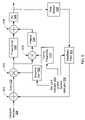
- FIG. 5is a signal flow diagram of an adaptive closed-loop-control algorithm, according to an embodiment of the invention.
- FIG. 6Ais a graph that shows a set point as indicated by a set point indicator, according to an embodiment of the invention.
- FIG. 6Bis a graph that shows a value of a feedback time constant associated with a feedback filter within an adaptive closed-loop-control algorithm, according to an embodiment of the invention.
- FIG. 6Cis a graph that shows a set point error as calculated by an adaptive closed-loop-control algorithm, according to an embodiment of the invention.
- FIG. 6Dis a graph that shows an integral control signal calculated using an adaptive closed-loop-control algorithm, according to an embodiment of the invention.
- FIG. 6Eis a graph that shows a valve position of a valve that is controlled by a flow controller implementing an adaptive closed-loop-control algorithm, according to an embodiment of the invention.
- FIG. 6Fis a graph that shows an actual flow of a fluid through a valve that is controlled using an adaptive closed-loop-control algorithm, according to an embodiment of the invention.
- FIG. 6Gis a graph that shows a signal from a flow sensor measuring a flow of a fluid through a valve that is controlled using an adaptive closed-loop-algorithm, according to an embodiment of the invention.
- the present inventionis directed to an adaptive closed-loop algorithm (e.g., a proportional-integral-derivative (PID) algorithm) that is implemented on a controller.
- the controllerin some embodiments is a mass flow controller that is configured to deliver a fluid either in a gaseous state (e.g., nitrogen) and/or a liquid state (e.g., hydrochloric acid) to, for example, a tool in a semiconductor facility.
- a gaseous statee.g., nitrogen
- a liquid statee.g., hydrochloric acid
- the closed-loop-control algorithmin several embodiments adapted to changing conditions by modifying a response time of the algorithm.
- a mass flow controller operating in accordance with many embodiments of the adaptive algorithmis capable of operating with a fast response when an existing flow rate is substantially below a desired flow rate and capable of operating with a slower response, which is less prone to noise, when the existing flow rate is relatively close to the desired flow rate.
- the response time of the adaptive algorithmis adjusted when one or more defined threshold conditions are satisfied based on one or more indicators.
- the response time of the adaptive closed-loop-control algorithm in these embodimentsis modified in response to a sensor indicator received from a sensor (e.g., pressure sensor, flow sensor) and/or a set point indicator when the threshold condition(s) is satisfied.
- the sensor indicatorindicates a value of an attribute (e.g., flow rate) associated with a fluid flowing through and controlled by, for example, a valve within a flow controller.
- the set point indicatorindicates the set point used by, for example, a flow controller to control a flow of a fluid.
- the response time of the adaptive closed-loop-control algorithmis modified when a value of at least one of the indicators (e.g., set point indicator and/or sensor indicator) exceeds or falls below a threshold value associated with the indicator.
- the response time of the adaptive closed-loop-control algorithmis modified when a calculated value based on a sensor indicator satisfies a threshold condition (e.g., rate of change or maximum allowable change over a specified period of time).
- a threshold conditione.g., rate of change or maximum allowable change over a specified period of time.
- the modificationis based on an error signal, which is the difference between a set point and a sensor indicator, satisfying a threshold condition.
- the response time of the adaptive closed-loop-control algorithmis modified when a magnitude of a change in at least one of the indicators (e.g., set point and/or sensor) exceeds or falls below a threshold value.
- the response time of the adaptive closed-loop-control algorithmis modified by accelerating and decelerating, for example, a filter (e.g., feedback filter) associated with the closed-loop-control algorithm.
- a parametere.g., tuning parameter
- an adaptive gainfor example, is also modified in response to a sensor indicator and/or a set point indicator based on a defined threshold condition.
- the modifying of the response time of the adaptive closed-loop-control algorithmis based on a timer.
- FIG. Iillustrates a flow controller 100 that uses an adaptive closed-loop-control algorithm to control a flow of a fluid from a fluid dispenser 120 to a reaction vessel 180 .
- a change in a measured, calculated, and/or specified valuee.g., pressure indicator value, set point indicator value, flow sensor indicator value
- the adaptive closed-loop-control algorithmis modified from a slow response mode to a fast response mode, and vice versa, by the flow controller 100 .
- the flow controller 100uses a set point value to control the flow of the fluid from the fluid dispenser 120 to the reaction vessel 180 based on the adaptive closed-loop-control algorithm in the slow or the fast response mode.
- the fluidis a liquid (e.g., sulfuric acid) and in other embodiments a gas (e.g., nitrogen), but a person skilled in the art will appreciate, having the benefit of this disclosure, that the fluid being delivered by the flow controller 100 may be any kind of fluid including, for example, a mixture of elements and/or compounds in any phase, such as a gas or a liquid.
- the flow controller 100in many embodiments is configured to deliver a fluid under high pressure, low temperature, or to different types of containers or vessels.
- the flow controller 100in the exemplary embodiment receives indicators from a flow sensor 142 and a pressure sensor 144 that are upstream from the flow controller 100 .
- the indicator from the flow sensor 142indicates the flow rate of the fluid flowing from the fluid dispenser 120 and controlled by the flow controller 100 .
- the indicator from the pressure sensor 144indicates the pressure of the fluid from the fluid dispenser 120 and controlled by the flow controller 100 .
- the flow controlleralso receives a set point indicator 146 that indicates a fluid flow set point.
- the flow controller 100receives an indicator from another device or sensor such as a temperature sensor.
- one or more of the sensorsare located downstream from the flow controller 100 rather than upstream from the flow controller 100 .
- the flow sensor 142in many embodiments is realized by a thermal flow sensor, but in other embodiments a laminar flow sensor, coriolis flow sensor, ultrasonic flow sensor or differential pressure sensor are utilized.
- the pressure sensor 144is realized by a gage pressure sensor, differential sensor, absolute pressure sensor or piezoresistive pressure sensor. In variations, the flow sensor 102 and/or pressure sensor 144 are used in combination with any combination of other sensors (e.g., temperature sensors) to accurately measure the flow of the fluid.
- the flow controller 100 in this embodimentincludes a processor 102 , a valve 104 , and a memory 106 .
- the memory 106stores the adaptive closed-loop-control algorithm, which includes a PID control algorithm, filter equations, and parameters associated with the PID control algorithm and filter equations.
- the memory 106is any type of appropriate storage device that can be, but is not limited to, flash memory, a random access memory (RAM) and/or a hard disk.
- the memory 106also stores parameters (e.g., time periods) and/or equations (e.g., modification rate change equations) related to the modification of the adaptive closed-loop-control algorithm as well as threshold conditions.
- the adaptive closed-loop-control algorithm and associated parametersare biased so that the adaptive closed-loop-control algorithm has a slow response time (also referred to as a “slow mode” or “slow response mode”).
- a slow response timealso referred to as a “slow mode” or “slow response mode”.
- variable valve 104is any appropriate type of variable valve that changes the flow of the fluid in any way.
- the variable valve 104is a valve with a variable orifice or a valve with multiple pre-set positions.
- FIG. 1shows that the processor 102 , valve 104 , and memory 106 are integrated into the flow controller 100 in a single device, in some embodiments, the components are combined and/or separated into different components and/or devices.
- the memory 106is embedded into the processor 102 as, for example, a cache, or is integrated into a separate centralized server (not shown) that stores data for the flow controller 100 or for several distributed and/or cascaded flow controllers.
- the valve 104in some implementations, is a separate component from the flow controller 100 that is either upstream or downstream from, for example, the flow sensor 142 , pressure sensor 144 and/or flow controller 100 . In other implementations, the flow sensor 142 and/or pressure sensor 144 is integrated into the flow controller 100 .
- threshold conditions associated with the indicators from the sensors 142 and 144 and the set point indicator 146are also stored in the memory 106 .
- the threshold conditionsare defined so that when the threshold conditions are satisfied, the adaptive closed-loop-control algorithm is modified to have a fast response time (also referred to as a “fast mode” or “fast response mode”).
- the modification from a slow mode to a fast modecan be referred to as acceleration and the modification from a fast mode to a slow mode can be referred to as deceleration.
- the adaptive closed-loop-control algorithmis modified to have a fast response time by changing the parameters (stored in the memory 106 ) associated with the algorithm.
- the response time of the adaptive closed-loop-control algorithmis modified by changing filter equations associated with the algorithm rather than changing parameters associated with the algorithm.
- the processor 102is designed with, for example, a hardware implemented (e.g., firmware) adaptive closed-loop-control algorithm that accesses and uses parameters stored by the memory 106 . In this scenario, the processor 102 adjusts the parameters stored in the memory 106 to modify the response time of the adaptive closed-loop-control algorithm.
- the indicators from the sensors 142 and 144 and the set point indicator 146 in this embodimentare processed by the processor 102 using the adaptive closed-loop-control algorithm to control the valve 104 to produce the flow rate specified by the set point indicator 146 .
- the flow controller 100uses the adaptive closed-loop-control algorithm to adjust the flow rate of the fluid (e.g., via a control indicator sent to the valve 104 ) to conform with the new set point.
- the mode of the closed-loop-control algorithmis modified. For example, if a change in set point, as determined by the processor 102 , exceeds a set-point-change threshold condition (e.g., a maximum allowable set point change) the processor 102 modifies the adaptive closed-loop-control algorithm to have a fast mode. The processor 102 then controls the flow of fluid by sending control signals to the valve 104 based on the new set point and according to the adaptive closed-loop-control algorithm in the fast mode. When the new set point is reached, the processor 102 modifies the adaptive closed-loop-control algorithm, by adjusting parameters associated with the algorithm from the fast mode back to the slow mode.
- a set-point-change threshold conditione.g., a maximum allowable set point change
- the processor 102modifies the adaptive closed-loop-control algorithm from a slow mode to a fast mode and/or vice versa.
- the processor 102 within the flow controller 100is programmed to modify the adaptive closed-loop-control algorithm when a flow rate as indicated by the flow sensor 142 satisfies a threshold condition. For example, a modification of the adaptive closed-loop-control algorithm is triggered when the magnitude of a flow rate change, prompted by, for example, a change in pressure, exceeds a maximum allowable value within a specified period of time.
- the processor 102modifies the adaptive closed-loop-control algorithm from the fast response time configuration back to the slow response time configuration. In some embodiments, if the processor 102 detects that a change in, for example, a pressure sensor indicator exceeds a threshold condition associated with a change in pressure, the processor 102 is configured to modify the adaptive closed-loop-control algorithm from a slow mode to a fast mode and/or vice versa
- the level of modification of an adaptive closed-loop-control algorithmis based on the magnitude of a change relative to a threshold value. For example, if a set point change far exceeds a set-point-change threshold condition the parameters and/or filters associated with the adaptive closed-loop-control algorithm are modified more than if the set point change had barely satisfied the set-point-change threshold condition.
- FIG. 2it includes a flowchart that shows a method for modifying an adaptive closed-loop-control algorithm from a first mode to a second mode based on a defined threshold condition.
- the first modeis, for example, a slow, low noise mode
- the second modeis, for example, a fast and potentially noisy mode.
- the threshold conditionis defined as a magnitude of an error that (e.g., threshold value), when exceeded by a calculated error value, triggers a modification of the adaptive closed-loop-control algorithm from the first mode to the second mode.
- the error valuein many embodiments is the difference between a flow rate set point and a measured flow rate as indicated by a flow indicator.
- the adaptive closed-loop-control algorithmis modified from the second mode back to the first mode.
- the error valueis calculated based on flow set points and measurements
- the error value in other embodimentsis based on other set points and measurements such as pressure set points and measurements.
- a flow sensor indicatoris received and a flow of a fluid is controlled according to a flow set point using an adaptive closed-loop-control algorithm in the first mode based on the flow sensor indicator at 200 .
- an error valueis calculated at 210 as the difference between a flow rate indicated by the flow sensor indicator and the flow set point. If the error value does not exceed a defined threshold value at 220 , the flow sensor indicator continues to be received and fluid flow continues to be controlled using the adaptive closed-loop control algorithm in the first mode 200 .
- the adaptive closed-loop-control algorithmis modified from the first mode to the second mode 230 .
- a flow sensor indicatoris received and the fluid flow is controlled using the adaptive closed-loop-control algorithm in the second mode based on the flow sensor indicator at 240 .
- the adaptive closed-loop-control algorithm in the second modeis used to control the flow of the fluid according to the flow set point. Error values are continuously (or intermittently in some embodiments) calculated at 250 based on flow sensor indicators and the flow set point. If calculated error values continue to exceed the threshold value at 260 , the flow sensor indicator continues to be received and fluid flow is controlled using the adaptive closed-loop control algorithm in the second mode at 240 . When the calculated error value at 250 falls below the threshold value at 260 , the adaptive closed-loop-control algorithm is modified from the second mode back to the first mode at 270 .
- a temperature sensor indicatoris received from a temperature sensor and analyzed with respect to a threshold value associated with temperature.
- multiple sensorse.g., flow, temperature, and pressure sensors
- the threshold conditionis defined based on a set point indicator value rather than on a sensor indicator error value.
- the threshold conditionin some variations, is based on a rate of change of, for example, an error value from an indicator.
- the values (i.e., parameters) within a threshold conditionin several implementations, is defined based on empirical data related to, for example, a specific flow controller(s).
- a threshold value for modifying an adaptive closed-loop-control algorithm from a first mode to a second modeis different than a threshold value used for determining a change of the algorithm from the second mode back to the first mode.
- a threshold conditionis based on a complex combination (e.g., subtracted, multiplied) of values (e.g., time, pressure, etc.) or boolean conditions (e.g., “or” boolean condition). For example, the threshold condition is only satisfied when the values (or calculated values) derived from both a temperature indicator and a pressure indicator exceed their respective corresponding threshold values.
- the adaptive closed-loop-control algorithmis modified to one of several modes (e.g., moderately fast mode) based on threshold conditions that correspond with one or more of the modes.
- a threshold conditionis defined, for example, so that the adaptive closed-loop-control algorithm is modified only if more than three consecutive pressure indicator values and/or error values exceed a threshold value.
- a threshold conditionis defined, for example, so that the adaptive closed-loop-control algorithm is modified only if pressure indicator values exceed a threshold value for more than, for example, 300 milliseconds.
- FIG. 3is a flowchart that shows a method for modifying an adaptive closed-loop-control algorithm based on a defined threshold condition and based on a timer.
- the threshold conditionis a pressure value that, when exceeded by a value indicated by a pressure sensor indicator from a pressure sensor, triggers a modification of the adaptive closed-loop-control algorithm from the first mode to the second mode.
- the adaptive closed-loop-control algorithmis modified from the second mode back to the first mode when the timer expires.
- a pressure sensor indicatoris received and a flow of a fluid is controlled using an adaptive closed-loop-control algorithm in the first mode based on a flow sensor indicator at 300 .
- the pressure sensor indicatoris continuously (or intermittently in some embodiments) analyzed with reference to a threshold value at 310 when received. If a pressure value as indicated by the pressure sensor indicator does not exceed the threshold value at 310 , the pressure sensor indicator continues to be received and fluid flow continues to be controlled using the adaptive closed-loop control algorithm in the first mode at 300 .
- the adaptive closed-loop-control algorithmis modified from the first mode to the second mode at 320 and a timer is started at 330 .
- the timerruns for a time period of 3 seconds.
- Pressure sensor indicatorsare received and fluid flow is controlled using the adaptive closed-loop-control algorithm in the second mode based on flow sensor indicators 340 until the time period expires.
- the pressure sensor indicatorcontinues to be received and fluid flow is controlled based the algorithm in the second mode at 340 .
- the adaptive closed-loop-control algorithmis modified from the second mode back to the first mode at 360 .
- the length of the time perioddepends on factors such as response time of flow controllers or deviation of a sensor indicator above the corresponding threshold value. For example, in some embodiments, the time period used by the timer is longer when a value from a sensor exceeds a threshold value by a large amount than when a value from the sensor exceeds the threshold value by a small amount.
- the adaptive closed-loop-control algorithmis modified from a first mode to a second mode according to a mathematical equation so that the modification occurs, for example, at a slow rate rather than abruptly.
- the rate of modification and/or level of modification (e.g., , the level of acceleration or deceleration) of an adaptive closed-loop-control algorithm from one mode to anotherdepends on, for example, whether flow is increasing or decreasing.
- FIG. 4it is a flowchart that shows a method for modifying an adaptive closed-loop-control algorithm from a slow response mode to a fast response mode based on a set-point-change threshold condition.
- the set-point-change threshold conditionis a magnitude of set point change that, when exceeded by a set point change, triggers a modification of the adaptive closed-loop-control algorithm from the slow response mode to the fast response mode.
- a fluid flowis controlled using the adaptive closed-loop-control algorithm in a slow mode at 400 .
- the change in set pointis calculated at 420 and the change in set point is compared with a defined threshold value at 430 .
- the set point changeis less than the threshold value at 430
- fluid flowis controlled and adjusted to the new set point using the adaptive closed-loop-control algorithm in the slow response mode at 400 .
- the adaptive closed-loop-control algorithmis accelerated (e.g., modified) from the slow mode to the fast mode 440 .
- fluid flowis then controlled using the adaptive closed-loop-control algorithm in the fast response mode at 440 until the new set point is reached at 450 .
- fluid flowcontinues to be controlled using the adaptive closed-loop-control algorithm in the fast response mode at 440 .
- the adaptive closed-loop-control algorithmis decelerated (e.g., modified) from the fast response mode to the slow response mode at 460 .
- Fluid flowis then controlled using the adaptive closed-loop-control algorithm in the slow response mode at 400 .
- the algorithmis biased to control the flow of fluid in the slow response mode and only changes to the fast response mode when large set point changes occur.
- the adaptive closed-loop-control algorithmis biased to control the flow of fluid in, for example, a fast response mode.
- the speed of the response modeis based on the magnitude of the set point change. For example, the response mode is accelerated to one of several fast response modes that depend on the magnitude of the set point change as defined in one or more threshold conditions.
- the threshold value for a set point changeis zero so that the response time of the closed-loop-control algorithm is changed for any set point change.
- FIG. 5is a signal flow diagram of an exemplary adaptive closed-loop-control algorithm.
- Each of the blocks within the exemplary adaptive closed-loop-control algorithmis realized by a combination of equations with associated parameters and constants.
- the adaptive close-loop-control algorithm in this embodimentis based on a proportional-integral (PI) controller that includes a proportional control block 542 and an integral control block 544 .
- a tuning parameter 510 and a feedback filter 520are used to modify the response time of the closed-loop-control algorithm when a threshold condition is satisfied based on the values of a set point indicator 554 , a sensor indicator 556 , and/or a value derived (e.g., calculated error) using the set point indicator 554 and/or sensor indicator 556 .
- the set point indicator 554indicates a fluid flow set point.
- the sensor indicator 556includes a pressure sensor indicator from a pressure sensor (not shown) and a flow sensor indicator produced by the flow sensor 530 . In some embodiments, the sensor indicator 556 includes other sensor indicators such as temperature sensor indicators.
- a flow indicator(e.g., signal) from a flow sensor 530 is adjusted through the feedback filter 520 and subtracted at 572 from the set point indicated by the set point indicator 554 to produce an error 552 .
- a product 574 of the error 552 and an adaptive gain 500is used by the PI controller to control a valve Kv 546 .
- the equations, parameters and/or constants in blocks 500 , 510 , 520 , 530 , 542 , 544 , and 546are selected to stabilize the adaptive closed-loop-controller algorithm and to attain, for example, a specified response time and/or transient waveform (e.g., overshoot, damping) in each response time mode.
- This embodimentalso includes an adaptive gain 500 that is continuously (or intermittently in some embodiments) adjusted based on the values of the set point indicator 554 , sensor indicator 556 and/or values calculated using any combination of the set point indicator 554 and sensor indicator 556 .
- the adaptive gain 500is adjusted when a threshold condition is satisfied based on the set point indicator 554 and/or sensor indicator 556 .
- the adaptive gain 500is configured to correct for non-linearities such as, for example, Kv 546 non-linearities or non-linear pressure effects.
- the adaptive gain 500affects the speed of further valve position adjustment as calculated using the adaptive closed-loop-control algorithm.
- the adaptive gain 500is calculated based on, for example, flow sensitivity, valve sensitivity, and/or pressure sensitivity. With a proper adaptive gain 500 , the adaptive closed-loop-control algorithm is stable and has similar performance over ranges of, for example, pressures and/or set points.
- the tuning parameter 510 and feedback filter 520are modified when the set point indicator 554 , sensor indicator 556 and/or a value derived (e.g., calculated error) using the set point indicator 554 and/or sensor indicator 556 satisfies a defined threshold condition.
- the tuning parameter 510is modified substantially at the same time as the feedback filter 520 to stabilize the adaptive closed-loop-control algorithm when the feedback filter 520 is accelerated and/or decelerated.
- the tuning parameter 510 and feedback filter 520are adjusted based on different threshold conditions or combination threshold conditions. In some embodiments, rate and even waveform of parameters being adjusted when modifying the adaptive closed-loop-control algorithm are modified depending on whether fluid flow is increasing or decreasing.
- the adaptive closed-loop-control algorithmincludes, for example, derivative control in addition to proportional and integral control. In other embodiments, the control algorithm includes other combinations of proportional, integral, and/or derivative control.
- the tuning parameter 510is associated with a portion of the closed-loop-control algorithm (e.g., included as a parameter in the integral control block 544 or associated with a derivative control block).
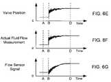
- FIGS. 6A-6Gare graphs that show exemplary measurements, signals, and calculated values related to an exemplary set point change that triggers an exemplary modification of a feedback filter within an adaptive closed-loop-control algorithm.
- the adaptive closed-loop-control algorithm in this embodimentis implemented on a flow controller that is controlling the flow of a fluid through a valve according to the set point.
- FIG. 6Ais a graph that shows a set point as indicated by a set point indicator.
- FIG. 6Ashows the set point change from X to Y at time B.
- FIG. 6Ashows that the magnitude of the set point change 600 is larger than the set-point-change threshold condition 610 , triggering a modification of the adaptive closed-loop-control algorithm.
- FIG. 6Bis a graph that shows a value of a feedback time constant associated with the feedback filter within the adaptive closed-loop-control algorithm.
- FIG. 6Bshows that at time B, the feedback time constant is changed from a high value shown at time A to a low value at time B in response to the set-point-change threshold condition being satisfied as shown in FIG. 6A .
- a high valuecauses the adaptive closed-loop-control algorithm to have a slow response time while a low value for a feedback time constant results in a faster response time for the adaptive closed-loop-control algorithm.
- FIG. 6Bshows that the value of the feedback time constant is slowly increased starting at time C until the value of the feedback time constant reaches its original value at time D.
- the value of the feedback time constantis held at the low value for a defined time period between B and C before the value of the feedback time constant is slowly increased.
- a tuning parameteris adjusted at substantially the same time as the feedback time constant to stabilize the adaptive closed-loop-control algorithm.
- FIG. 6Cis a graph that shows a set point error as calculated by the adaptive closed-loop-control algorithm.
- FIG. 6Cshows that the calculated set point error is zero before the set point change at time B shown in FIG. 6A .
- FIG. 6Cshows that when the set point changes at time B, the calculated set point error increases instantaneously.
- the adaptive closed-loop-control algorithmresponds to the calculated set point error, the set point error decreases until the set point is reached at time D when the error decreases to zero.
- FIG. 6Cshows that while the adaptive closed-loop-control algorithm in this embodiment is in a fast response mode, the calculated set point error is noisy.
- the curves in FIGS. 6D-6Glike the curve in FIG. 6C , exhibit noise while the adaptive closed-loop-control algorithm is in a fast response mode.
- FIG. 6Dis a graph that shows an integral control signal calculated using the adaptive closed-loop-control algorithm.
- FIG. 6Dshows that the integral control signal increases when the set point changes at time B until the signal is stabilized at time D.
- FIG. 6Eis a graph that shows a valve position of the valve that is controlled by the flow controller implementing the adaptive closed-loop-control algorithm.
- FIG. 6Eshows that the valve position changes in response to the set point change at time B until it reaches a steady-state position at time D.
- FIG. 6Fis a graph that shows an actual flow of fluid through the valve that is controlled using the adaptive closed-loop-control algorithm.
- FIG. 6Fshows that the actual fluid flow measurement tracks with the valve position in FIG. 6E .
- FIG. 6Gis a graph that shows a signal from a flow sensor measuring the flow of fluid flowing through the valve that is controlled using the adaptive closed-loop-algorithm.
- FIG. 6Gshows that the flow sensor signal, which has a slow response time, lags behind the actual fluid flow measurement in FIG. 6F .
- the present inventionprovides a system and method for controlling a flow of a fluid using an adaptive closed-loop-control algorithm.
Landscapes
- Engineering & Computer Science (AREA)
- Physics & Mathematics (AREA)
- General Physics & Mathematics (AREA)
- Automation & Control Theory (AREA)
- Health & Medical Sciences (AREA)
- Artificial Intelligence (AREA)
- Computer Vision & Pattern Recognition (AREA)
- Evolutionary Computation (AREA)
- Medical Informatics (AREA)
- Software Systems (AREA)
- Feedback Control In General (AREA)
- Flow Control (AREA)
Abstract
Description
Claims (25)
Priority Applications (7)
| Application Number | Priority Date | Filing Date | Title |
|---|---|---|---|
| US11/413,780US7603186B2 (en) | 2006-04-28 | 2006-04-28 | Adaptive response time closed loop control algorithm |
| PCT/US2007/067593WO2007127897A2 (en) | 2006-04-28 | 2007-04-27 | Adaptive response time closed loop control algorithm |
| KR1020087029193AKR101136841B1 (en) | 2006-04-28 | 2007-04-27 | Adaptive response time closed loop control algorithm |
| JP2009507977AJP5152178B2 (en) | 2006-04-28 | 2007-04-27 | Method for adapting response time of mass flow controller and mass flow controller |
| EP07761420AEP2013672A4 (en) | 2006-04-28 | 2007-04-27 | Adaptive response time closed loop control algorithm |
| CN2007800195351ACN101454735B (en) | 2006-04-28 | 2007-04-27 | Adaptive response time closed loop control algorithm |
| TW96121084ATWI413879B (en) | 2006-04-28 | 2007-06-11 | Method and apparatus for controlling flow of fluid using adaptive closed loop control algorithm |
Applications Claiming Priority (1)
| Application Number | Priority Date | Filing Date | Title |
|---|---|---|---|
| US11/413,780US7603186B2 (en) | 2006-04-28 | 2006-04-28 | Adaptive response time closed loop control algorithm |
Publications (2)
| Publication Number | Publication Date |
|---|---|
| US20070276545A1 US20070276545A1 (en) | 2007-11-29 |
| US7603186B2true US7603186B2 (en) | 2009-10-13 |
Family
ID=38656403
Family Applications (1)
| Application Number | Title | Priority Date | Filing Date |
|---|---|---|---|
| US11/413,780Active2027-04-16US7603186B2 (en) | 2006-04-28 | 2006-04-28 | Adaptive response time closed loop control algorithm |
Country Status (7)
| Country | Link |
|---|---|
| US (1) | US7603186B2 (en) |
| EP (1) | EP2013672A4 (en) |
| JP (1) | JP5152178B2 (en) |
| KR (1) | KR101136841B1 (en) |
| CN (1) | CN101454735B (en) |
| TW (1) | TWI413879B (en) |
| WO (1) | WO2007127897A2 (en) |
Cited By (11)
| Publication number | Priority date | Publication date | Assignee | Title |
|---|---|---|---|---|
| US20080295892A1 (en)* | 2007-06-04 | 2008-12-04 | Horiba Stec, Co., Ltd. | Mass flow controller |
| US20090312876A1 (en)* | 2006-10-03 | 2009-12-17 | Horiba Stec, Co., Ltd. | Mass flow controller |
| US20110015791A1 (en)* | 2009-07-14 | 2011-01-20 | Advanced Energy Industries, Inc. | Thermal mass flow sensor with improved response across fluid types |
| US20110190909A1 (en)* | 2010-02-01 | 2011-08-04 | Johnson Controls Technology Company | Systems and methods for increasing feedback controller response times |
| US20110307104A1 (en)* | 2010-06-10 | 2011-12-15 | Advanced Energy Industries, Inc. | Adaptive On-Tool Mass Flow Controller Tuning |
| KR20140122743A (en) | 2012-02-03 | 2014-10-20 | 히타치 긴조쿠 가부시키가이샤 | Device and program for flow rate control |
| US9989956B2 (en) | 2016-05-11 | 2018-06-05 | Saudi Arabian Oil Company | Split range control using proportional-integral control with flow valves |
| US10245608B2 (en) | 2014-05-01 | 2019-04-02 | Graco Minnesota Inc. | Method for flow control calibration of high-transient systems |
| US10550552B2 (en) | 2014-05-01 | 2020-02-04 | Graco Minnesota Inc. | Method for fluid pressure control in a closed system |
| US10753356B2 (en) | 2015-05-01 | 2020-08-25 | Graco Minnesota Inc. | Adaptive flow control |
| US12123760B2 (en) | 2019-05-14 | 2024-10-22 | Fujikin Incorporated | Flow rate control device, flow rate control method, control program for flow rate control device |
Families Citing this family (24)
| Publication number | Priority date | Publication date | Assignee | Title |
|---|---|---|---|---|
| US7853364B2 (en) | 2006-11-30 | 2010-12-14 | Veeco Instruments, Inc. | Adaptive controller for ion source |
| US8079383B2 (en)* | 2006-12-07 | 2011-12-20 | Mks Instruments, Inc. | Controller gain scheduling for mass flow controllers |
| US8195312B2 (en)* | 2009-08-27 | 2012-06-05 | Hitachi Metals, Ltd | Multi-mode control loop with improved performance for mass flow controller |
| JP5499381B2 (en)* | 2009-10-20 | 2014-05-21 | 日立金属株式会社 | Flow control device |
| US8945094B2 (en)* | 2010-09-08 | 2015-02-03 | Honeywell International Inc. | Apparatus and method for medication delivery using single input-single output (SISO) model predictive control |
| AR091524A1 (en)* | 2012-06-20 | 2015-02-11 | Fisher Controls Int | METHODS AND SYSTEMS FOR BACKUP OF MINOR LOOP FEEDBACK |
| US9004107B2 (en)* | 2012-08-21 | 2015-04-14 | Applied Materials, Inc. | Methods and apparatus for enhanced gas flow rate control |
| WO2014160663A1 (en) | 2013-03-27 | 2014-10-02 | Schlumberger Canada Limited | Interface for automation client |
| KR102166360B1 (en) | 2013-08-28 | 2020-10-16 | 가부시키가이샤 호리바 에스텍 | Flow-rate control device and flow-rate control program |
| PL2910865T3 (en) | 2014-02-21 | 2017-02-28 | Plum Sp. Z O.O. | System amd method for controlling a fan insufflating ait into a protected space, especially in fire ventilation for the protection of escape routes |
| CA2945051C (en)* | 2014-04-11 | 2022-07-26 | Bristol, Inc., D/B/A Remote Automation Solutions | Injection flow controller for water and steam |
| JP6001600B2 (en)* | 2014-06-26 | 2016-10-05 | 株式会社日本自動車部品総合研究所 | System for controlling gas supply unit and gas filling method |
| WO2017201489A1 (en) | 2016-05-20 | 2017-11-23 | Moog Inc. | Secure and traceable manufactured parts |
| US11204597B2 (en) | 2016-05-20 | 2021-12-21 | Moog Inc. | Outer space digital logistics system |
| JP2018018942A (en)* | 2016-07-27 | 2018-02-01 | 東京エレクトロン株式会社 | Liquid processing apparatus and liquid processing method |
| CN107041282A (en)* | 2017-01-20 | 2017-08-15 | 青岛农业大学 | It is a kind of to realize the water-fertilizer integral algorithm and controller of closed-loop control |
| CN109506028B (en)* | 2017-09-15 | 2020-02-21 | 武汉海翼科技有限公司 | Quick follow-up control method of pressure regulating valve |
| KR102516673B1 (en)* | 2017-12-20 | 2023-03-31 | 무그 인코포레이티드 | Space digital logistics system |
| US11209298B2 (en)* | 2018-04-27 | 2021-12-28 | Hitachi Metals, Ltd. | Thermal mass flow sensor with improved accuracy |
| US10969797B2 (en)* | 2018-08-29 | 2021-04-06 | Illinois Tool Works, Inc. | Mass flow valve controller and control method with set point filter and linearization system based on valve model |
| DK3690592T3 (en)* | 2019-01-30 | 2021-07-05 | Siemens Schweiz Ag | Control valve |
| CN111495633B (en)* | 2020-04-26 | 2021-04-27 | 佛山科学技术学院 | A kind of paint closed-loop supply system and control method based on Faster-rcnn |
| WO2022056069A1 (en)* | 2020-09-09 | 2022-03-17 | Lenovo (United States) Inc. A Corporation Of Delaware | Method and apparatus including event triggered goal change for control loops |
| CN117391404B (en)* | 2023-12-11 | 2024-05-10 | 深圳市曼恩斯特科技股份有限公司 | Control method and device for coating transverse surface density of lithium battery and electronic equipment |
Citations (28)
| Publication number | Priority date | Publication date | Assignee | Title |
|---|---|---|---|---|
| US4218733A (en) | 1978-11-13 | 1980-08-19 | Sybron Corporation | Adaptive gain controller |
| US5129418A (en) | 1989-11-14 | 1992-07-14 | Stec Inc. | Mass flow controller with supplemental condition sensors |
| US5394322A (en)* | 1990-07-16 | 1995-02-28 | The Foxboro Company | Self-tuning controller that extracts process model characteristics |
| US5410495A (en) | 1993-07-20 | 1995-04-25 | Texas Instruments Incorporated | Apparatus, systems, and methods for diagnosing anomalous mass flow controller operation |
| US5609136A (en)* | 1994-06-28 | 1997-03-11 | Cummins Engine Company, Inc. | Model predictive control for HPI closed-loop fuel pressure control system |
| US5691896A (en)* | 1995-08-15 | 1997-11-25 | Rosemount, Inc. | Field based process control system with auto-tuning |
| US6272401B1 (en)* | 1997-07-23 | 2001-08-07 | Dresser Industries, Inc. | Valve positioner system |
| US6289923B1 (en) | 1998-05-29 | 2001-09-18 | Fujikin Incorporated | Gas supply system equipped with pressure-type flow rate control unit |
| US6314992B1 (en) | 1998-08-24 | 2001-11-13 | Fujikin Incorporated | Fluid-switchable flow rate control system |
| US6389364B1 (en)* | 1999-07-10 | 2002-05-14 | Mykrolis Corporation | System and method for a digital mass flow controller |
| US6445980B1 (en)* | 1999-07-10 | 2002-09-03 | Mykrolis Corporation | System and method for a variable gain proportional-integral (PI) controller |
| US6466893B1 (en)* | 1997-09-29 | 2002-10-15 | Fisher Controls International, Inc. | Statistical determination of estimates of process control loop parameters |
| US6575027B1 (en)* | 1999-07-09 | 2003-06-10 | Mykrolis Corporation | Mass flow sensor interface circuit |
| US6598617B2 (en)* | 2000-09-05 | 2003-07-29 | Guy Kevin Spicer | Cascaded variable bias feedforward and feedback flow and level control system |
| US20030141925A1 (en)* | 2002-01-30 | 2003-07-31 | Lennous Paul A. | Adjustable time constant integrator |
| WO2003100391A1 (en) | 2002-05-24 | 2003-12-04 | Mykrolis Corporation | System and method for mass flow detection device calibration |
| US20030236592A1 (en) | 2002-06-24 | 2003-12-25 | Ali Shajii | Apparatus and method for mass flow controller with network access to diagnostics |
| WO2004001516A1 (en) | 2002-06-24 | 2003-12-31 | Mks Instruments, Inc. | Apparatus and method for pressure fluctuation insensitive mass flow control |
| WO2004010234A2 (en) | 2002-07-19 | 2004-01-29 | Celerity Group, Inc. | Methods and apparatus for pressure compensation in a mass flow controller |
| US6712084B2 (en) | 2002-06-24 | 2004-03-30 | Mks Instruments, Inc. | Apparatus and method for pressure fluctuation insensitive mass flow control |
| US20040122353A1 (en) | 2002-12-19 | 2004-06-24 | Medtronic Minimed, Inc. | Relay device for transferring information between a sensor system and a fluid delivery system |
| US6782906B2 (en) | 2000-12-28 | 2004-08-31 | Young-Chul Chang | Time based mass flow controller and method for controlling flow rate using it |
| US6843122B2 (en) | 2002-12-27 | 2005-01-18 | Taesan Lcd. Co., Ltd. | Mass flow controller for control purge and managing method of the same |
| US20050027373A1 (en) | 2001-06-05 | 2005-02-03 | Florentin Woergoetter | Controller and method of controlling an apparatus |
| US6868862B2 (en) | 2002-06-24 | 2005-03-22 | Mks Instruments, Inc. | Apparatus and method for mass flow controller with a plurality of closed loop control code sets |
| US20050166968A1 (en) | 2001-04-24 | 2005-08-04 | Lull John M. | System and method for a mass flow controller |
| US6955072B2 (en) | 2003-06-25 | 2005-10-18 | Mks Instruments, Inc. | System and method for in-situ flow verification and calibration |
| US7069944B2 (en)* | 2003-02-24 | 2006-07-04 | Smc Corporation | Flow rate control device |
Family Cites Families (5)
| Publication number | Priority date | Publication date | Assignee | Title |
|---|---|---|---|---|
| GB1416401A (en)* | 1973-03-06 | 1975-12-03 | Rolls Royce | Control systems |
| US5875109A (en)* | 1995-05-24 | 1999-02-23 | Johnson Service Company | Adaptive flow controller for use with a flow control system |
| JP3240436B2 (en)* | 1997-02-10 | 2001-12-17 | 油研工業株式会社 | Hydraulic elevator equipment |
| US6487458B1 (en)* | 1999-08-31 | 2002-11-26 | Delphi Technologies, Inc. | Adaptive closed-loop servo control |
| KR101006537B1 (en)* | 2002-06-24 | 2011-01-07 | 엠케이에스 인스트루먼츠 인코포레이티드 | Mass flow control unit not affected by pressure fluctuations |
- 2006
- 2006-04-28USUS11/413,780patent/US7603186B2/enactiveActive
- 2007
- 2007-04-27CNCN2007800195351Apatent/CN101454735B/enactiveActive
- 2007-04-27WOPCT/US2007/067593patent/WO2007127897A2/enactiveApplication Filing
- 2007-04-27JPJP2009507977Apatent/JP5152178B2/enactiveActive
- 2007-04-27EPEP07761420Apatent/EP2013672A4/ennot_activeWithdrawn
- 2007-04-27KRKR1020087029193Apatent/KR101136841B1/enactiveActive
- 2007-06-11TWTW96121084Apatent/TWI413879B/enactive
Patent Citations (39)
| Publication number | Priority date | Publication date | Assignee | Title |
|---|---|---|---|---|
| US4218733A (en) | 1978-11-13 | 1980-08-19 | Sybron Corporation | Adaptive gain controller |
| US5129418A (en) | 1989-11-14 | 1992-07-14 | Stec Inc. | Mass flow controller with supplemental condition sensors |
| US5394322A (en)* | 1990-07-16 | 1995-02-28 | The Foxboro Company | Self-tuning controller that extracts process model characteristics |
| US5410495A (en) | 1993-07-20 | 1995-04-25 | Texas Instruments Incorporated | Apparatus, systems, and methods for diagnosing anomalous mass flow controller operation |
| US5609136A (en)* | 1994-06-28 | 1997-03-11 | Cummins Engine Company, Inc. | Model predictive control for HPI closed-loop fuel pressure control system |
| US5691896A (en)* | 1995-08-15 | 1997-11-25 | Rosemount, Inc. | Field based process control system with auto-tuning |
| US6272401B1 (en)* | 1997-07-23 | 2001-08-07 | Dresser Industries, Inc. | Valve positioner system |
| US20010037159A1 (en)* | 1997-07-23 | 2001-11-01 | Henry Boger | Valve positioner system |
| US6453261B2 (en)* | 1997-07-23 | 2002-09-17 | Dresser, Inc. | Valve positioner system |
| US6745084B2 (en)* | 1997-07-23 | 2004-06-01 | Dresser, Inc. | Valve positioner system |
| US6466893B1 (en)* | 1997-09-29 | 2002-10-15 | Fisher Controls International, Inc. | Statistical determination of estimates of process control loop parameters |
| US6289923B1 (en) | 1998-05-29 | 2001-09-18 | Fujikin Incorporated | Gas supply system equipped with pressure-type flow rate control unit |
| US6314992B1 (en) | 1998-08-24 | 2001-11-13 | Fujikin Incorporated | Fluid-switchable flow rate control system |
| US6575027B1 (en)* | 1999-07-09 | 2003-06-10 | Mykrolis Corporation | Mass flow sensor interface circuit |
| US6714878B2 (en)* | 1999-07-10 | 2004-03-30 | Mykrolis Corporation | System and method for a digital mass flow controller |
| US6389364B1 (en)* | 1999-07-10 | 2002-05-14 | Mykrolis Corporation | System and method for a digital mass flow controller |
| US6445980B1 (en)* | 1999-07-10 | 2002-09-03 | Mykrolis Corporation | System and method for a variable gain proportional-integral (PI) controller |
| US6598617B2 (en)* | 2000-09-05 | 2003-07-29 | Guy Kevin Spicer | Cascaded variable bias feedforward and feedback flow and level control system |
| US6782906B2 (en) | 2000-12-28 | 2004-08-31 | Young-Chul Chang | Time based mass flow controller and method for controlling flow rate using it |
| US6962164B2 (en)* | 2001-04-24 | 2005-11-08 | Celerity Group, Inc. | System and method for a mass flow controller |
| US20050167627A1 (en) | 2001-04-24 | 2005-08-04 | Lull John M. | System and method for a mass flow controller |
| US20050166968A1 (en) | 2001-04-24 | 2005-08-04 | Lull John M. | System and method for a mass flow controller |
| US7107108B2 (en)* | 2001-06-05 | 2006-09-12 | Florentin Woergoetter | Controller and method of controlling an apparatus using predictive filters |
| US20050027373A1 (en) | 2001-06-05 | 2005-02-03 | Florentin Woergoetter | Controller and method of controlling an apparatus |
| US20030141925A1 (en)* | 2002-01-30 | 2003-07-31 | Lennous Paul A. | Adjustable time constant integrator |
| WO2003100391A1 (en) | 2002-05-24 | 2003-12-04 | Mykrolis Corporation | System and method for mass flow detection device calibration |
| US20030236592A1 (en) | 2002-06-24 | 2003-12-25 | Ali Shajii | Apparatus and method for mass flow controller with network access to diagnostics |
| US6868862B2 (en) | 2002-06-24 | 2005-03-22 | Mks Instruments, Inc. | Apparatus and method for mass flow controller with a plurality of closed loop control code sets |
| US6712084B2 (en) | 2002-06-24 | 2004-03-30 | Mks Instruments, Inc. | Apparatus and method for pressure fluctuation insensitive mass flow control |
| US6932098B2 (en) | 2002-06-24 | 2005-08-23 | Mks Instruments, Inc. | Apparatus and method for pressure fluctuation insensitive mass flow control |
| WO2004001516A1 (en) | 2002-06-24 | 2003-12-31 | Mks Instruments, Inc. | Apparatus and method for pressure fluctuation insensitive mass flow control |
| US20040074311A1 (en) | 2002-07-19 | 2004-04-22 | Celerity Group, Inc. | Methods and apparatus for pressure compensation in a mass flow controller |
| US20050223813A1 (en) | 2002-07-19 | 2005-10-13 | Celerity Group, Inc. | Methods and apparatus for pressure compensation in a mass flow controller |
| WO2004010234A2 (en) | 2002-07-19 | 2004-01-29 | Celerity Group, Inc. | Methods and apparatus for pressure compensation in a mass flow controller |
| US7073392B2 (en)* | 2002-07-19 | 2006-07-11 | Celerity, Inc. | Methods and apparatus for pressure compensation in a mass flow controller |
| US20040122353A1 (en) | 2002-12-19 | 2004-06-24 | Medtronic Minimed, Inc. | Relay device for transferring information between a sensor system and a fluid delivery system |
| US6843122B2 (en) | 2002-12-27 | 2005-01-18 | Taesan Lcd. Co., Ltd. | Mass flow controller for control purge and managing method of the same |
| US7069944B2 (en)* | 2003-02-24 | 2006-07-04 | Smc Corporation | Flow rate control device |
| US6955072B2 (en) | 2003-06-25 | 2005-10-18 | Mks Instruments, Inc. | System and method for in-situ flow verification and calibration |
Non-Patent Citations (1)
| Title |
|---|
| International Search Report and Written Opinion, Mailed Jul. 21, 2008; Lee W. Young; Alexandria, VA, USA. |
Cited By (18)
| Publication number | Priority date | Publication date | Assignee | Title |
|---|---|---|---|---|
| US20090312876A1 (en)* | 2006-10-03 | 2009-12-17 | Horiba Stec, Co., Ltd. | Mass flow controller |
| US7881829B2 (en)* | 2006-10-03 | 2011-02-01 | Horiba Stec Co., Ltd. | Mass flow controller |
| US20080295892A1 (en)* | 2007-06-04 | 2008-12-04 | Horiba Stec, Co., Ltd. | Mass flow controller |
| US8056579B2 (en)* | 2007-06-04 | 2011-11-15 | Horiba Stec, Co., Ltd. | Mass flow controller |
| US8160833B2 (en)* | 2009-07-14 | 2012-04-17 | Hitachi Metals, Ltd | Thermal mass flow sensor with improved response across fluid types |
| US20110015791A1 (en)* | 2009-07-14 | 2011-01-20 | Advanced Energy Industries, Inc. | Thermal mass flow sensor with improved response across fluid types |
| US20110190909A1 (en)* | 2010-02-01 | 2011-08-04 | Johnson Controls Technology Company | Systems and methods for increasing feedback controller response times |
| US8428755B2 (en)* | 2010-02-01 | 2013-04-23 | Johnson Controls Technology Company | Systems and methods for increasing feedback controller response times |
| US8131400B2 (en)* | 2010-06-10 | 2012-03-06 | Hitachi Metals, Ltd. | Adaptive on-tool mass flow controller tuning |
| US20110307104A1 (en)* | 2010-06-10 | 2011-12-15 | Advanced Energy Industries, Inc. | Adaptive On-Tool Mass Flow Controller Tuning |
| KR20140122743A (en) | 2012-02-03 | 2014-10-20 | 히타치 긴조쿠 가부시키가이샤 | Device and program for flow rate control |
| US9797520B2 (en) | 2012-02-03 | 2017-10-24 | Hitachi Metals, Ltd. | Flow control apparatus and program |
| US10245608B2 (en) | 2014-05-01 | 2019-04-02 | Graco Minnesota Inc. | Method for flow control calibration of high-transient systems |
| US10550552B2 (en) | 2014-05-01 | 2020-02-04 | Graco Minnesota Inc. | Method for fluid pressure control in a closed system |
| US11492786B2 (en) | 2014-05-01 | 2022-11-08 | Graco Minnesota Inc. | Method for fluid pressure control in a closed system |
| US10753356B2 (en) | 2015-05-01 | 2020-08-25 | Graco Minnesota Inc. | Adaptive flow control |
| US9989956B2 (en) | 2016-05-11 | 2018-06-05 | Saudi Arabian Oil Company | Split range control using proportional-integral control with flow valves |
| US12123760B2 (en) | 2019-05-14 | 2024-10-22 | Fujikin Incorporated | Flow rate control device, flow rate control method, control program for flow rate control device |
Also Published As
| Publication number | Publication date |
|---|---|
| CN101454735A (en) | 2009-06-10 |
| EP2013672A4 (en) | 2010-09-08 |
| WO2007127897A3 (en) | 2008-09-18 |
| JP5152178B2 (en) | 2013-02-27 |
| TW200848967A (en) | 2008-12-16 |
| EP2013672A2 (en) | 2009-01-14 |
| CN101454735B (en) | 2013-07-17 |
| KR101136841B1 (en) | 2012-04-19 |
| JP2009535716A (en) | 2009-10-01 |
| WO2007127897A2 (en) | 2007-11-08 |
| KR20090007470A (en) | 2009-01-16 |
| US20070276545A1 (en) | 2007-11-29 |
| TWI413879B (en) | 2013-11-01 |
Similar Documents
| Publication | Publication Date | Title |
|---|---|---|
| US7603186B2 (en) | Adaptive response time closed loop control algorithm | |
| US20080009978A1 (en) | Multi-mode control algorithm | |
| US7971604B2 (en) | Flow controller delivery of a specified-quantity of a fluid | |
| KR101995610B1 (en) | Adaptive pressure insensitive mass flow controller and method for multi-gas applications | |
| US9898013B2 (en) | Mass flow controller for improved performance across fluid types | |
| KR101847409B1 (en) | Method and system of on-tool and on-site mfc optimization providing consistent response | |
| US20090312876A1 (en) | Mass flow controller | |
| US20130037112A1 (en) | Mass Flow Controller Algorithm with Adaptive Valve Start Position | |
| JP2009535716A5 (en) | ||
| KR20090096427A (en) | Controller gain scheduling for mass flow controllers | |
| AU2001294045B2 (en) | Method of and system for controlling the ratio of a variable lead parameter and an adjustable lag parameter for lag-lead process | |
| US20080295892A1 (en) | Mass flow controller | |
| AU2001294045A1 (en) | Method of and system for controlling the ratio of a variable lead parameter and an adjustable lag parameter for lag-lead process | |
| US10884436B2 (en) | Flow rate signal correction method and flow rate control device employing same | |
| US12098940B2 (en) | Pressure control system, pressure control method, and pressure control program | |
| JP2001202103A (en) | Plant control method and control device | |
| JP2025018873A (en) | Flow Control Device |
Legal Events
| Date | Code | Title | Description |
|---|---|---|---|
| AS | Assignment | Owner name:ADVANCED ENERGY INDUSTRIES, INC., COLORADO Free format text:ASSIGNMENT OF ASSIGNORS INTEREST;ASSIGNOR:SMIRNOV, ALEXEI V.;REEL/FRAME:018786/0833 Effective date:20060505 | |
| STCF | Information on status: patent grant | Free format text:PATENTED CASE | |
| AS | Assignment | Owner name:HITACHI METALS, LTD., JAPAN Free format text:ASSIGNMENT OF ASSIGNORS INTEREST;ASSIGNOR:ADVANCED ENERGY INDUSTRIES, INC.;REEL/FRAME:025217/0675 Effective date:20100929 | |
| FEPP | Fee payment procedure | Free format text:PAYOR NUMBER ASSIGNED (ORIGINAL EVENT CODE: ASPN); ENTITY STATUS OF PATENT OWNER: LARGE ENTITY | |
| FPAY | Fee payment | Year of fee payment:4 | |
| FPAY | Fee payment | Year of fee payment:8 | |
| MAFP | Maintenance fee payment | Free format text:PAYMENT OF MAINTENANCE FEE, 12TH YEAR, LARGE ENTITY (ORIGINAL EVENT CODE: M1553); ENTITY STATUS OF PATENT OWNER: LARGE ENTITY Year of fee payment:12 | |
| AS | Assignment | Owner name:PROTERIAL, LTD., JAPAN Free format text:CHANGE OF NAME;ASSIGNOR:HITACHI METALS, LTD.;REEL/FRAME:068944/0752 Effective date:20230104 Owner name:HITACHI METALS, LTD., JAPAN Free format text:CHANGE OF ADDRESS;ASSIGNOR:HITACHI METALS, LTD.;REEL/FRAME:068943/0854 Effective date:20220621 Owner name:HITACHI METALS, LTD., JAPAN Free format text:CHANGE OF ADDRESS;ASSIGNOR:HITACHI METALS, LTD.;REEL/FRAME:068943/0622 Effective date:20151201 | |
| AS | Assignment | Owner name:HITACHI METALS, LTD., JAPAN Free format text:CORRECTIVE ASSIGNMENT TO CORRECT THE THE PATENT NUMBER FROM 8671972 TO 8504311 PREVIOUSLY RECORDED ON REEL 68943 FRAME 622. ASSIGNOR(S) HEREBY CONFIRMS THE CHANGE OF ADDRESS;ASSIGNOR:HITACHI METALS, LTD.;REEL/FRAME:069959/0644 Effective date:20151201 Owner name:HITACHI METALS, LTD., JAPAN Free format text:CORRECTIVE ASSIGNMENT TO CORRECT THE CHANGING PATENT NUMBER 8671972 TO 8504311 PREVIOUSLY RECORDED AT REEL: 68943 FRAME: 854. ASSIGNOR(S) HEREBY CONFIRMS THE CHANGE OF ADDRESS;ASSIGNOR:HITACHI METALS, LTD.;REEL/FRAME:069959/0507 Effective date:20220621 Owner name:PROTERIAL, LTD., JAPAN Free format text:CORRECTIVE ASSIGNMENT TO CORRECT THE PATENT NUMBER FROM 8671972 TO 8504311 PREVIOUSLY RECORDED ON REEL 68944 FRAME 752. ASSIGNOR(S) HEREBY CONFIRMS THE CHANGE OF NAME;ASSIGNOR:HITACHI METALS, LTD.;REEL/FRAME:069959/0902 Effective date:20230104 |