US7603098B2 - Programmable IF frequency filter for enabling a compromise between DC offset rejection and image rejection - Google Patents
Programmable IF frequency filter for enabling a compromise between DC offset rejection and image rejectionDownload PDFInfo
- Publication number
- US7603098B2 US7603098B2US10/813,270US81327004AUS7603098B2US 7603098 B2US7603098 B2US 7603098B2US 81327004 AUS81327004 AUS 81327004AUS 7603098 B2US7603098 B2US 7603098B2
- Authority
- US
- United States
- Prior art keywords
- rejection
- offset
- compromise
- image rejection
- filter
- Prior art date
- Legal status (The legal status is an assumption and is not a legal conclusion. Google has not performed a legal analysis and makes no representation as to the accuracy of the status listed.)
- Expired - Fee Related, expires
Links
- 238000000034methodMethods0.000claimsdescription13
- 238000001914filtrationMethods0.000claimsdescription10
- 238000005259measurementMethods0.000claimsdescription9
- 238000006880cross-coupling reactionMethods0.000claims2
- 238000004891communicationMethods0.000description34
- 238000010586diagramMethods0.000description6
- 230000001413cellular effectEffects0.000description5
- 230000008859changeEffects0.000description2
- 238000012986modificationMethods0.000description2
- 230000004048modificationEffects0.000description2
- 230000009466transformationEffects0.000description2
- 239000000969carrierSubstances0.000description1
- 230000008878couplingEffects0.000description1
- 238000010168coupling processMethods0.000description1
- 238000005859coupling reactionMethods0.000description1
- 230000003247decreasing effectEffects0.000description1
- 238000010295mobile communicationMethods0.000description1
- 230000008569processEffects0.000description1
Images


Classifications
- H—ELECTRICITY
- H04—ELECTRIC COMMUNICATION TECHNIQUE
- H04B—TRANSMISSION
- H04B1/00—Details of transmission systems, not covered by a single one of groups H04B3/00 - H04B13/00; Details of transmission systems not characterised by the medium used for transmission
- H04B1/06—Receivers
- H04B1/10—Means associated with receiver for limiting or suppressing noise or interference
- H04B1/12—Neutralising, balancing, or compensation arrangements
- H04B1/123—Neutralising, balancing, or compensation arrangements using adaptive balancing or compensation means
- H—ELECTRICITY
- H03—ELECTRONIC CIRCUITRY
- H03G—CONTROL OF AMPLIFICATION
- H03G3/00—Gain control in amplifiers or frequency changers
- H03G3/20—Automatic control
- H03G3/30—Automatic control in amplifiers having semiconductor devices
- H03G3/3052—Automatic control in amplifiers having semiconductor devices in bandpass amplifiers (H.F. or I.F.) or in frequency-changers used in a (super)heterodyne receiver
- H—ELECTRICITY
- H03—ELECTRONIC CIRCUITRY
- H03J—TUNING RESONANT CIRCUITS; SELECTING RESONANT CIRCUITS
- H03J3/00—Continuous tuning
- H03J3/02—Details
- H03J3/06—Arrangements for obtaining constant bandwidth or gain throughout tuning range or ranges
- H—ELECTRICITY
- H03—ELECTRONIC CIRCUITRY
- H03G—CONTROL OF AMPLIFICATION
- H03G2201/00—Indexing scheme relating to subclass H03G
- H03G2201/70—Gain control characterized by the gain control parameter
- H03G2201/706—Gain control characterized by the gain control parameter being quality indicator, e.g. BER,C/I
Definitions
- This inventionrelates generally to wireless communication systems, and more particularly, but not exclusively, to a programmable IF frequency filter that enables a compromise between DC offset rejection and image rejection.
- Communication systemsare known to support wireless and wire lined communications between wireless and/or wire lined communication devices. Such communication systems range from national and/or international cellular telephone systems to the Internet to point-to-point in-home wireless networks. Each type of communication system is constructed, and hence operates, in accordance with one or more communication standards. For instance, wireless communication systems may operate in accordance with one or more standards including, but not limited to, IEEE 802.11, Bluetooth, advanced mobile phone services (AMPS), digital AMPS, global system for mobile communications (GSM), code division multiple access (CDMA), and/or variations thereof.
- GSMglobal system for mobile communications
- CDMAcode division multiple access
- a wireless communication devicesuch as a cellular telephone, two-way radio, personal digital assistant (PDA), personal computer (PC), laptop computer, home entertainment equipment, et cetera communicates directly or indirectly with other wireless communication devices.
- the participating wireless communication devicestune their receivers and transmitters to the same channel or channel pair (e.g., one of the plurality of radio frequency (RF) carriers of the wireless communication system) and communicate over that channel or channel pair.
- RFradio frequency
- each wireless communication devicecommunicates directly with an associated base station (e.g., for cellular services) and/or an associated access point (e.g., for an in-home or in-building wireless network) via an assigned channel.
- the associated base stations and/or associated access pointscommunicate with each other directly, via a system controller, via the public switch telephone network, via the internet, and/or via some other wide area network.
- each wireless communication deviceFor each wireless communication device to participate in wireless communications, it includes a built-in radio transceiver (i.e., receiver and transmitter) or is coupled to an associated radio transceiver (e.g., a station for in-home and/or in-building wireless communication networks, RF modem, etc.).
- the receiverreceives RF signals, removes the RF carrier frequency from the RF signals directly or via one or more intermediate frequency stages, and demodulates the signals in accordance with a particular wireless communication standard to recapture the transmitted data.
- the transmitterconverts data into RF signals by modulating the data to RF carrier in accordance with the particular wireless communication standard and directly or in one or more intermediate frequency stages to produce the RF signals.
- Embodiments of the inventionenable a compromise between DC offset rejection and image rejection through the use of a bandpass filter having a variable center frequency.
- a methodcomprises: filtering a signal with a bandpass filter; measuring image rejection and DC offset rejection of the filtered signal; and adjusting a center frequency of the bandpass filter.
- a systeme.g., circuit
- a bandpass filtercapable of filtering a received signal and capable of having a center frequency adjusted
- at least one measurement circuitcommunicatively coupled to the filter, capable of measuring image rejection and DC offset rejection of the filtered signal.
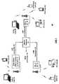
- FIG. 1is a block diagram illustrating a network system according to an embodiment of the present invention
- FIG. 2is a circuit diagram illustrating a receiver
- FIG. 3is a chart illustrating an IF frequency shift to transform a low pass filter into a bandpass filter
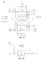
- FIGS. 4A and 4Bare diagrams illustrating a channel select filter (bandpass filter) of the receiver IF section of FIG. 2 and its electrical equivalent, respectively;
- FIG. 5A and FIG. 5Bare charts illustrating shifting the IF frequency of the channel select filter (bandpass filter) to overcome DC offset rejection and image rejection, respectively;
- FIG. 6is a flowchart illustrating a method for IF frequency selection according to an embodiment of the invention.
- FIG. 1is a block diagram illustrating a network system 10 according to an embodiment of the present invention.
- the system 10includes a plurality of base stations and/or access points 12 - 16 , a plurality of wireless communication devices 18 - 32 and a network hardware component 34 .
- the wireless communication devices 18 - 32may be laptop host computers 18 and 26 , personal digital assistant hosts 20 and 30 , personal computer hosts 24 and 32 and/or cellular telephone hosts 22 and 28 .
- the base stations or access points 12are operably coupled to the network hardware 34 via local area network connections 36 , 38 and 40 .
- the network hardware 34which may be a router, switch, bridge, modem, system controller, etc. provides a wide area network connection 42 for the communication system 10 .
- Each of the base stations or access points 12 - 16has an associated antenna or antenna array to communicate with the wireless communication devices in its area.
- the wireless communication devicesregister with a particular base station or access point 12 - 14 to receive services from the communication system 10 .
- For direct connectionsi.e., point-to-point communications
- wireless communication devicescommunicate directly via an allocated channel.
- each wireless communication deviceincludes a built-in radio and/or is coupled to a radio.
- the radioincludes a transmitter capable of adjusting power amplifier output power and therefore has characteristics of reduced power requirements, thereby extending the life of an associated power supply.
- FIG. 2is a circuit diagram illustrating a receiver 200 with low-intermediate frequency, which is 100 KHz in this embodiment.
- An antenna 205is coupled to a low noise amplifier (LNA) 210 , which is coupled to down converters (mixers) 220 and 225 .
- the down converters 220 and 225are coupled to bandpass filters (BPFs) 230 and 235 , respectively, which are coupled to programmable gain stages 240 and 245 , respectively.
- the gain stages 240 and 245are coupled to gain stages 250 and 255 respectively, which output analog signals to measurement circuits 285 and 290 , respectively.
- an LO generator 280is coupled to to the down converters 220 and 225 .
- a wideband radio signal strength indicator (WRSSI) 215is coupled to connections between the down converters 220 and 225 and the bandpass filters 230 and 235 .
- WRSSIwideband radio signal strength indicator
- the antenna 205receives signals and passes the signals to the LNA 210 , which amplifies the received signals and passes them to the down converters 220 and 225 , which shifts the frequency of the received signals downwards.
- the BPFs 230 and 235discriminate against unwanted frequencies outside of a selected band.
- the BPFs 230 and 235also perform channel selection to compromise between image rejection and DC offset rejection, as will be discussed in further detail below.
- each BPF 230 and 235can comprise 3 biquads with configurations as shown in Table I below.
- Each BPF 230 and 235can have gain settings of 30 dB, 20 dB, 10 dB and 0 dB.
- IFcan be centered at 112 KHz, 108 KHz, 104 KHz, and 100 KHz. Further, the BPFs 230 and 235 can change the IQ polarity.
- Control wordswill vary the coupling resistor 410 values, which is Rx in FIG. 4 , and change the IF frequency of the channel select filter 400 .
- Control words for changing the channel selection (frequency selection) of the BPFs 230 and 235are shown in Tables II below.
- the LO generator 280determines how to bring an incoming RF signal received at the antenna 205 down to 100 KHz.
- the gain stages 240 - 255increase the gain of the BPFs 230 and 235 output.
- the measurement circuits 285 and 290measure the DC offset rejection and image rejection of the filtered signals and provide feedback to the BPFs 230 and 235 so that a new IF frequency can be chosen to form a better compromise between DC offset rejection and image rejection.
- FIG. 3is a chart illustrating an IF frequency shift 300 to transform a low pass filter into a bandpass filter.
- the transformationcan be done by the variation of resistance in the BPFs 230 and 235 as derived below based on the circuits shown in FIG. 4A and FIG. 4B below.
- the transformationalso enables IF frequency shifting to compensate for DC offset rejection and image rejection.
- FIG. 4A and FIG. 4Bare diagrams illustrating a channel select filter 400 (e.g., bandpass filters 230 and 235 ) and its electrical equivalent, respectively.
- the filter 400is an active RC filter that enables achievement of a high dynamic range.
- the filter 400comprises two cross coupled low pass filters having cross coupled variable resistors 410 , each having a resistance R x .
- variation of R xshifts the bandpass filter IF frequency up or down.
- the IF frequency of the filter 400is inversely proportional to R x .
- a signalis filtered by the filter 400 with the resistors 410 set to an initial default value.
- the filtered signalsare then transmitted to the measurement circuits 285 and 290 where image rejection and DC offset rejection are measured.
- the circuits 285 and 290provide feedback to the resistors 410 , which are then adjusted and the measurements repeated after filtering again. This process is repeated until a compromise is established between DC offset rejection and image rejection (e.g., wherein image rejection meets minimum pre-specified requirements and the DC offset rejection is within acceptable tolerances.).
- FIG. 5A and FIG. 5Bare charts 500 A and 500 B illustrating shifting the IF frequency of the channel select filter 400 (e.g., bandpass filters 230 and 235 ) to overcome DC offset rejection and image rejection, respectively.
- the IF frequency of the filter 400is shifted upwards to improve DC offset rejection (as shown in FIG. 5A ) and downwards to improve image rejection (as shown in FIG. 5B ) until a compromise is reached.
- FIG. 6is a flowchart illustrating a method 600 for IF frequency selection according to an embodiment of the invention.
- the IF receiver section 200may implement the method 600 .
- the IF center frequencyis adjusted ( 610 ) by varying resistance of the resistors 410 .
- a received signalis then filtered ( 620 ) using a bandpass filter using the adjusted frequency.
- Image rejection and DC offset rejection of the filtered signalis then measured ( 630 , 640 ). It is then determined ( 650 ) if the measurements are within a specific tolerance (e.g., DC offset rejection is within acceptable tolerances and image rejection meet minimum pre-specified requirements). If the measurements are within the tolerances, the method 600 ends. Otherwise, the center frequency is then adjusted ( 610 ) again and the method 600 repeats.
- a specific tolerancee.g., DC offset rejection is within acceptable tolerances and image rejection meet minimum pre-specified requirements
Landscapes
- Engineering & Computer Science (AREA)
- Computer Networks & Wireless Communication (AREA)
- Signal Processing (AREA)
- Noise Elimination (AREA)
- Circuits Of Receivers In General (AREA)
- Transceivers (AREA)
- Networks Using Active Elements (AREA)
- Superheterodyne Receivers (AREA)
Abstract
Description
| TABLE I |
| (Center Frequency of 100 KHz) |
| Biquad1 | Biquad2 | Biquad3 | ||
| 100 KHz | 186 KHz | 13.4 | |
| Frequency | |||
| BW | |||
| 200 | 100 | 100 KHz | |
| Q | 0.5 | 1.866 | 0.134 |
| 20 dB, 0 | 10 dB, 0 | 0 | |
| 30 | 20 | 10 | 0 |
| 20 | 20 | 0 | 0 |
| 10 | 0 | 10 | 0 |
| 0 | 0 | 0 | 0 dB |
| Current | 1.7 mA | 1.7 mA | 1.7 mA |
| (I and Q) | (I and Q) | (I and Q) | |
| TABLE II | |||
| Center Frequency | |||
| BPF Center Frequency | Control Word (4 bit) | ||
| 112 KHz | 1000 | ||
| 108 KHz | 0100 | ||
| 104 KHz | 0010 | ||
| 100 KHz | 0001 | ||
- For a low pass filter:
- wherein ωois the corner frequency.
- For a bandpass filter:
- wherein ωcis the center frequency.
- Therefore, for the channel select filter electrical equivalent420 (
FIG. 4B ):
- Therefore,
Claims (9)
Priority Applications (9)
| Application Number | Priority Date | Filing Date | Title |
|---|---|---|---|
| US10/813,270US7603098B2 (en) | 2004-03-31 | 2004-03-31 | Programmable IF frequency filter for enabling a compromise between DC offset rejection and image rejection |
| US10/840,271US7603085B2 (en) | 2004-03-31 | 2004-05-07 | Bandpass filter with integrated variable gain function |
| US10/865,951US7596195B2 (en) | 2004-03-31 | 2004-06-14 | Bandpass filter with reversible IQ polarity to enable a high side or low side injection receiver architecture |
| US10/879,588US7376409B2 (en) | 2004-03-31 | 2004-06-30 | Bandpass filter with integrated variable gain function using improved resistor array |
| DE602005004322TDE602005004322T2 (en) | 2004-03-31 | 2005-03-01 | Programmable IF filter to achieve a compromise between DC offset rejection and image rejection |
| EP05004477AEP1583247B1 (en) | 2004-03-31 | 2005-03-01 | Programmable IF frequency filter for enabling a compromise between DC offset rejection and image rejection |
| CNB2005100600143ACN100433544C (en) | 2004-03-31 | 2005-03-24 | Programmable if frequency filter for enabling a compromise between DC offset rejection and phase frequency interference rejection |
| TW094110007ATWI271940B (en) | 2004-03-31 | 2005-03-30 | Programmable if frequency filter for enabling a compromise between DC offset rejection and image rejection |
| US12/544,486US8675777B2 (en) | 2004-03-31 | 2009-08-20 | Programmable if frequency filter for enabling a compromise between DC offset rejection and image rejection |
Applications Claiming Priority (1)
| Application Number | Priority Date | Filing Date | Title |
|---|---|---|---|
| US10/813,270US7603098B2 (en) | 2004-03-31 | 2004-03-31 | Programmable IF frequency filter for enabling a compromise between DC offset rejection and image rejection |
Related Parent Applications (1)
| Application Number | Title | Priority Date | Filing Date |
|---|---|---|---|
| US10/840,271ContinuationUS7603085B2 (en) | 2004-03-31 | 2004-05-07 | Bandpass filter with integrated variable gain function |
Related Child Applications (2)
| Application Number | Title | Priority Date | Filing Date |
|---|---|---|---|
| US10/840,271Continuation-In-PartUS7603085B2 (en) | 2004-03-31 | 2004-05-07 | Bandpass filter with integrated variable gain function |
| US10/865,951Continuation-In-PartUS7596195B2 (en) | 2004-03-31 | 2004-06-14 | Bandpass filter with reversible IQ polarity to enable a high side or low side injection receiver architecture |
Publications (2)
| Publication Number | Publication Date |
|---|---|
| US20050221783A1 US20050221783A1 (en) | 2005-10-06 |
| US7603098B2true US7603098B2 (en) | 2009-10-13 |
Family
ID=34887701
Family Applications (3)
| Application Number | Title | Priority Date | Filing Date |
|---|---|---|---|
| US10/813,270Expired - Fee RelatedUS7603098B2 (en) | 2004-03-31 | 2004-03-31 | Programmable IF frequency filter for enabling a compromise between DC offset rejection and image rejection |
| US10/840,271Expired - Fee RelatedUS7603085B2 (en) | 2004-03-31 | 2004-05-07 | Bandpass filter with integrated variable gain function |
| US10/879,588Expired - Fee RelatedUS7376409B2 (en) | 2004-03-31 | 2004-06-30 | Bandpass filter with integrated variable gain function using improved resistor array |
Family Applications After (2)
| Application Number | Title | Priority Date | Filing Date |
|---|---|---|---|
| US10/840,271Expired - Fee RelatedUS7603085B2 (en) | 2004-03-31 | 2004-05-07 | Bandpass filter with integrated variable gain function |
| US10/879,588Expired - Fee RelatedUS7376409B2 (en) | 2004-03-31 | 2004-06-30 | Bandpass filter with integrated variable gain function using improved resistor array |
Country Status (5)
| Country | Link |
|---|---|
| US (3) | US7603098B2 (en) |
| EP (1) | EP1583247B1 (en) |
| CN (1) | CN100433544C (en) |
| DE (1) | DE602005004322T2 (en) |
| TW (1) | TWI271940B (en) |
Cited By (1)
| Publication number | Priority date | Publication date | Assignee | Title |
|---|---|---|---|---|
| US20100015939A1 (en)* | 2004-03-31 | 2010-01-21 | Broadcom Corporation | Programmable if frequency filter for enabling a compromise between dc offset rejection and image rejection |
Families Citing this family (13)
| Publication number | Priority date | Publication date | Assignee | Title |
|---|---|---|---|---|
| US7603098B2 (en)* | 2004-03-31 | 2009-10-13 | Broadcom Corporation | Programmable IF frequency filter for enabling a compromise between DC offset rejection and image rejection |
| JP2006121146A (en)* | 2004-10-19 | 2006-05-11 | Renesas Technology Corp | Filter control apparatus and method of wireless receiver, and integrated circuit for wireless receiver employing the same |
| US8831552B1 (en)* | 2005-06-15 | 2014-09-09 | Marvell International Ltd. | RF band pass filter with feedback control |
| JP4928748B2 (en)* | 2005-06-27 | 2012-05-09 | ルネサスエレクトロニクス株式会社 | Semiconductor device and manufacturing method thereof |
| US7613439B2 (en) | 2005-09-16 | 2009-11-03 | Broadcom Corporation | Programmable baseband filters supporting auto-calibration for a mobile digital cellular television environment |
| US7969222B2 (en)* | 2005-09-16 | 2011-06-28 | Broadcom Corporation | Method and system for DC offset correction loop for a mobile digital cellular television environment |
| JP2007221663A (en)* | 2006-02-20 | 2007-08-30 | Neuro Solution Corp | Broadcasting signal receiving apparatus |
| US7711342B2 (en)* | 2007-02-27 | 2010-05-04 | Pine Valley Investments, Inc. | Signal adjustment techniques |
| JP2011160214A (en)* | 2010-02-01 | 2011-08-18 | Renesas Electronics Corp | Receiving apparatus and image rejection method |
| US9269993B2 (en)* | 2010-05-04 | 2016-02-23 | Gram Power, Inc. | Rechargeable multipurpose smart power source |
| DE102010043730A1 (en)* | 2010-11-10 | 2012-05-10 | Intel Mobile Communications GmbH | A current-to-voltage converter, receiver, method of providing a voltage signal and method of receiving a received signal |
| GB201907717D0 (en)* | 2019-05-31 | 2019-07-17 | Nordic Semiconductor Asa | Apparatus and methods for dc-offset estimation |
| CN114257211B (en)* | 2022-03-02 | 2022-05-03 | 华南理工大学 | Variable bandwidth active RC filter and gain setting method thereof |
Citations (48)
| Publication number | Priority date | Publication date | Assignee | Title |
|---|---|---|---|---|
| DE3223904A1 (en) | 1982-06-26 | 1983-12-29 | Robert Bosch Gmbh, 7000 Stuttgart | Filter and demodulation circuit |
| US4724407A (en) | 1983-10-07 | 1988-02-09 | Hitachi, Ltd. | Integrated filter circuit having switchable selected parallel filter paths |
| US4857778A (en) | 1988-01-28 | 1989-08-15 | Maxim Integrated Products | Programmable universal active filter |
| US4866779A (en) | 1988-07-13 | 1989-09-12 | Delco Electronics Corporation | Adaptive AM audio processor |
| US4914408A (en) | 1988-06-02 | 1990-04-03 | U.S. Philips Corporation | Asymmetric polyphase filter |
| US4928315A (en) | 1987-12-21 | 1990-05-22 | Hughes Aircraft Company | Chirped backscatter filter |
| US4965853A (en) | 1988-10-12 | 1990-10-23 | U.S. Philips Corp. | Radio receiver circuit with tuning feedback control for a tunable bandpass filter |
| US5028893A (en) | 1990-03-21 | 1991-07-02 | Delco Electronics Corporation | Switched capacitor filters with continuous time control |
| US5140703A (en)* | 1988-10-14 | 1992-08-18 | Payne Christopher P | Modulation distortion analyzer |
| EP0542520A2 (en) | 1991-11-14 | 1993-05-19 | Nokia Mobile Phones Ltd. | Adjustable filter means |
| US5285502A (en) | 1992-03-31 | 1994-02-08 | Auditory System Technologies, Inc. | Aid to hearing speech in a noisy environment |
| US5307372A (en)* | 1985-07-19 | 1994-04-26 | Clinicom Incorporated | Radio transceiver for transmitting and receiving data packets |
| US5535283A (en) | 1992-12-28 | 1996-07-09 | Kabushiki Kaisha Toshiba | Active noise attenuating device |
| US5629655A (en) | 1992-10-27 | 1997-05-13 | Ericsson Inc. | Integrated distributed RC low-pass filters |
| EP0797292A1 (en) | 1996-03-19 | 1997-09-24 | Koninklijke Philips Electronics N.V. | Integrated receiver |
| US5726974A (en)* | 1995-06-20 | 1998-03-10 | Matsushita Electric Industrial Co., Ltd. | Receiving circuit having a frequency compensated local oscillation circuit |
| US5933448A (en)* | 1995-08-07 | 1999-08-03 | Nokia Telecommunications Oy | Automatic tuning of a radio transceiver |
| EP0948128A1 (en) | 1998-04-03 | 1999-10-06 | Motorola Semiconducteurs S.A. | DC offset cancellation in a quadrature receiver |
| US6055282A (en)* | 1998-04-06 | 2000-04-25 | Motorola | Digitally sampled phase quantized FM detector for a communication receiver |
| US20010001759A1 (en)* | 1998-02-04 | 2001-05-24 | Holden Alan R. | Apparatus and methods for tuning bandpass filters |
| US6370370B1 (en) | 1998-07-02 | 2002-04-09 | Sabine Roth | Method for improving the wanted signal in a radio receiving unit |
| US20020071173A1 (en) | 1998-07-14 | 2002-06-13 | Chang-Hee Lee | Dynamically tunable optical amplifier and fiber optic light source |
| US20020094037A1 (en)* | 2000-11-27 | 2002-07-18 | Hooman Darabi | IF FSK receiver |
| US6437639B1 (en) | 2000-07-18 | 2002-08-20 | Lucent Technologies Inc. | Programmable RC filter |
| US20020115420A1 (en) | 2001-02-20 | 2002-08-22 | Ting-Yuan Cheng | Frequency-lock filtering receiver and the method for the same |
| US6441682B1 (en)* | 1999-11-23 | 2002-08-27 | Micro Linear Corporation | Active polyphase filter with transconductor cross-coupling of filter sections |
| US6445735B1 (en) | 1999-02-08 | 2002-09-03 | Visteon Global Technologies, Inc. | Switched bandwidth digital filters with reduced transients during switching |
| US20030016761A1 (en)* | 2001-07-21 | 2003-01-23 | Lg Electronics Inc. | Method and apparatus for controlling digital filter of a radio transmitter |
| US20030017817A1 (en)* | 2001-07-19 | 2003-01-23 | Cowley Nicholas Paul | Tuner |
| US20030064695A1 (en) | 2001-09-28 | 2003-04-03 | Hong Shi | LNA gain adjustment in an RF receiver to compensate for intermodulation interference |
| US6559740B1 (en) | 2001-12-18 | 2003-05-06 | Delta Microwave, Inc. | Tunable, cross-coupled, bandpass filter |
| US6577855B1 (en) | 1998-08-25 | 2003-06-10 | U.S. Philips Corporation | Low IF receiver |
| US20030165203A1 (en)* | 2001-08-10 | 2003-09-04 | Rishi Mohindra | Quadrature gain and phase imbalance correction in a receiver |
| US6633550B1 (en) | 1997-02-20 | 2003-10-14 | Telefonaktiebolaget Lm Ericsson (Publ) | Radio transceiver on a chip |
| US20040002311A1 (en)* | 2002-06-28 | 2004-01-01 | Shen Feng | Offset compensation in a direct-conversion receiver |
| US20040247132A1 (en) | 1995-07-28 | 2004-12-09 | Klayman Arnold I. | Acoustic correction apparatus |
| US20040266369A1 (en) | 2003-06-30 | 2004-12-30 | Mccallister Ronald D. | Methods and apparatus for controlling signals |
| US6892060B2 (en) | 2002-06-28 | 2005-05-10 | Institute Of Microelectronics | Fully integrated self-tuned image rejection downconversion system |
| US20050118975A1 (en) | 2003-12-02 | 2005-06-02 | Ismail Aly M. | DC offset cancellation in a wireless receiver |
| US6917252B1 (en) | 2003-04-28 | 2005-07-12 | Adam S. Wyszynski | Fully integrated automatically-tuned RF and IF active bandpass filters |
| US20050221789A1 (en) | 2004-03-31 | 2005-10-06 | Broadcom Corporation | Bandpass filter with integrated variable gain function using improved resistor array |
| US20050220223A1 (en) | 2004-03-31 | 2005-10-06 | Broadcom Corporation | Bandpass filter with reversible IQ polarity to enable a high side or low side injection receiver architecture |
| US7050778B1 (en)* | 2000-09-18 | 2006-05-23 | Broadcom Corporation | Direct conversion turner |
| US20060153403A1 (en) | 2002-08-05 | 2006-07-13 | Thomas Lechner | Signal strength imformation dependent control of small electrodynamic transducers in audio systems |
| US7098731B1 (en) | 2004-01-13 | 2006-08-29 | Wyszynski Adam S | Synthesis method for an active polyphase filter |
| US7120416B2 (en)* | 2002-07-24 | 2006-10-10 | Fujitsu Limited | Semiconductor device and receiver |
| US7138873B2 (en) | 2004-11-17 | 2006-11-21 | Chandra Gaurav | Filter circuit providing low distortion and enhanced flexibility to obtain variable gain amplification |
| US7171185B2 (en)* | 2002-01-29 | 2007-01-30 | Matsushita Electric Industrial Co., Ltd. | Direct conversion receiver and DC offset reducing method |
Family Cites Families (9)
| Publication number | Priority date | Publication date | Assignee | Title |
|---|---|---|---|---|
| GB2049332B (en)* | 1979-04-30 | 1983-03-30 | Philips Electronic Associated | Active filter |
| JP2531353B2 (en)* | 1993-07-21 | 1996-09-04 | 日本電気株式会社 | Wireless receiver |
| DE69618540T2 (en)* | 1995-10-31 | 2002-09-05 | Koninklijke Philips Electronics N.V., Eindhoven | Filter device for processing a plurality of channels in a cable television distribution system |
| US6009129A (en)* | 1997-02-28 | 1999-12-28 | Nokia Mobile Phones | Device and method for detection and reduction of intermodulation distortion |
| US6778594B1 (en)* | 2000-06-12 | 2004-08-17 | Broadcom Corporation | Receiver architecture employing low intermediate frequency and complex filtering |
| US6973296B2 (en)* | 2001-12-04 | 2005-12-06 | Intersil Americas Inc. | Soft decision gain compensation for receive filter attenuation |
| US6718167B2 (en)* | 2002-08-01 | 2004-04-06 | Agere Systems Inc. | Filter center frequency temperature compensation by adjustment of the operating frequency of the host system |
| JP2004180281A (en)* | 2002-11-13 | 2004-06-24 | Renesas Technology Corp | Orthogonal mixer circuit and mobile terminal using the same |
| US20060009186A1 (en)* | 2004-07-08 | 2006-01-12 | Bin Liu | Receiver front-end filtering using low pass filtering and equalization |
- 2004
- 2004-03-31USUS10/813,270patent/US7603098B2/ennot_activeExpired - Fee Related
- 2004-05-07USUS10/840,271patent/US7603085B2/ennot_activeExpired - Fee Related
- 2004-06-30USUS10/879,588patent/US7376409B2/ennot_activeExpired - Fee Related
- 2005
- 2005-03-01DEDE602005004322Tpatent/DE602005004322T2/ennot_activeExpired - Lifetime
- 2005-03-01EPEP05004477Apatent/EP1583247B1/ennot_activeExpired - Lifetime
- 2005-03-24CNCNB2005100600143Apatent/CN100433544C/ennot_activeExpired - Fee Related
- 2005-03-30TWTW094110007Apatent/TWI271940B/ennot_activeIP Right Cessation
Patent Citations (50)
| Publication number | Priority date | Publication date | Assignee | Title |
|---|---|---|---|---|
| DE3223904A1 (en) | 1982-06-26 | 1983-12-29 | Robert Bosch Gmbh, 7000 Stuttgart | Filter and demodulation circuit |
| US4724407A (en) | 1983-10-07 | 1988-02-09 | Hitachi, Ltd. | Integrated filter circuit having switchable selected parallel filter paths |
| US5307372A (en)* | 1985-07-19 | 1994-04-26 | Clinicom Incorporated | Radio transceiver for transmitting and receiving data packets |
| US4928315A (en) | 1987-12-21 | 1990-05-22 | Hughes Aircraft Company | Chirped backscatter filter |
| US4857778A (en) | 1988-01-28 | 1989-08-15 | Maxim Integrated Products | Programmable universal active filter |
| US4914408A (en) | 1988-06-02 | 1990-04-03 | U.S. Philips Corporation | Asymmetric polyphase filter |
| US4866779A (en) | 1988-07-13 | 1989-09-12 | Delco Electronics Corporation | Adaptive AM audio processor |
| US4965853A (en) | 1988-10-12 | 1990-10-23 | U.S. Philips Corp. | Radio receiver circuit with tuning feedback control for a tunable bandpass filter |
| US5140703A (en)* | 1988-10-14 | 1992-08-18 | Payne Christopher P | Modulation distortion analyzer |
| US5028893A (en) | 1990-03-21 | 1991-07-02 | Delco Electronics Corporation | Switched capacitor filters with continuous time control |
| EP0542520A2 (en) | 1991-11-14 | 1993-05-19 | Nokia Mobile Phones Ltd. | Adjustable filter means |
| US5285502A (en) | 1992-03-31 | 1994-02-08 | Auditory System Technologies, Inc. | Aid to hearing speech in a noisy environment |
| US5629655A (en) | 1992-10-27 | 1997-05-13 | Ericsson Inc. | Integrated distributed RC low-pass filters |
| US5535283A (en) | 1992-12-28 | 1996-07-09 | Kabushiki Kaisha Toshiba | Active noise attenuating device |
| US5726974A (en)* | 1995-06-20 | 1998-03-10 | Matsushita Electric Industrial Co., Ltd. | Receiving circuit having a frequency compensated local oscillation circuit |
| US20040247132A1 (en) | 1995-07-28 | 2004-12-09 | Klayman Arnold I. | Acoustic correction apparatus |
| US5933448A (en)* | 1995-08-07 | 1999-08-03 | Nokia Telecommunications Oy | Automatic tuning of a radio transceiver |
| EP0797292A1 (en) | 1996-03-19 | 1997-09-24 | Koninklijke Philips Electronics N.V. | Integrated receiver |
| US6633550B1 (en) | 1997-02-20 | 2003-10-14 | Telefonaktiebolaget Lm Ericsson (Publ) | Radio transceiver on a chip |
| US20010001759A1 (en)* | 1998-02-04 | 2001-05-24 | Holden Alan R. | Apparatus and methods for tuning bandpass filters |
| EP0948128A1 (en) | 1998-04-03 | 1999-10-06 | Motorola Semiconducteurs S.A. | DC offset cancellation in a quadrature receiver |
| US6055282A (en)* | 1998-04-06 | 2000-04-25 | Motorola | Digitally sampled phase quantized FM detector for a communication receiver |
| US6370370B1 (en) | 1998-07-02 | 2002-04-09 | Sabine Roth | Method for improving the wanted signal in a radio receiving unit |
| US20020071173A1 (en) | 1998-07-14 | 2002-06-13 | Chang-Hee Lee | Dynamically tunable optical amplifier and fiber optic light source |
| US6577855B1 (en) | 1998-08-25 | 2003-06-10 | U.S. Philips Corporation | Low IF receiver |
| US6445735B1 (en) | 1999-02-08 | 2002-09-03 | Visteon Global Technologies, Inc. | Switched bandwidth digital filters with reduced transients during switching |
| US6441682B1 (en)* | 1999-11-23 | 2002-08-27 | Micro Linear Corporation | Active polyphase filter with transconductor cross-coupling of filter sections |
| US6437639B1 (en) | 2000-07-18 | 2002-08-20 | Lucent Technologies Inc. | Programmable RC filter |
| US7050778B1 (en)* | 2000-09-18 | 2006-05-23 | Broadcom Corporation | Direct conversion turner |
| US20020094037A1 (en)* | 2000-11-27 | 2002-07-18 | Hooman Darabi | IF FSK receiver |
| US20020115420A1 (en) | 2001-02-20 | 2002-08-22 | Ting-Yuan Cheng | Frequency-lock filtering receiver and the method for the same |
| US20030017817A1 (en)* | 2001-07-19 | 2003-01-23 | Cowley Nicholas Paul | Tuner |
| US20030016761A1 (en)* | 2001-07-21 | 2003-01-23 | Lg Electronics Inc. | Method and apparatus for controlling digital filter of a radio transmitter |
| US20030165203A1 (en)* | 2001-08-10 | 2003-09-04 | Rishi Mohindra | Quadrature gain and phase imbalance correction in a receiver |
| US20030064695A1 (en) | 2001-09-28 | 2003-04-03 | Hong Shi | LNA gain adjustment in an RF receiver to compensate for intermodulation interference |
| US6559740B1 (en) | 2001-12-18 | 2003-05-06 | Delta Microwave, Inc. | Tunable, cross-coupled, bandpass filter |
| US7171185B2 (en)* | 2002-01-29 | 2007-01-30 | Matsushita Electric Industrial Co., Ltd. | Direct conversion receiver and DC offset reducing method |
| US6892060B2 (en) | 2002-06-28 | 2005-05-10 | Institute Of Microelectronics | Fully integrated self-tuned image rejection downconversion system |
| US20040002311A1 (en)* | 2002-06-28 | 2004-01-01 | Shen Feng | Offset compensation in a direct-conversion receiver |
| US7120416B2 (en)* | 2002-07-24 | 2006-10-10 | Fujitsu Limited | Semiconductor device and receiver |
| US20060153403A1 (en) | 2002-08-05 | 2006-07-13 | Thomas Lechner | Signal strength imformation dependent control of small electrodynamic transducers in audio systems |
| US6917252B1 (en) | 2003-04-28 | 2005-07-12 | Adam S. Wyszynski | Fully integrated automatically-tuned RF and IF active bandpass filters |
| US20040266369A1 (en) | 2003-06-30 | 2004-12-30 | Mccallister Ronald D. | Methods and apparatus for controlling signals |
| US20050118975A1 (en) | 2003-12-02 | 2005-06-02 | Ismail Aly M. | DC offset cancellation in a wireless receiver |
| US7098731B1 (en) | 2004-01-13 | 2006-08-29 | Wyszynski Adam S | Synthesis method for an active polyphase filter |
| US20050220223A1 (en) | 2004-03-31 | 2005-10-06 | Broadcom Corporation | Bandpass filter with reversible IQ polarity to enable a high side or low side injection receiver architecture |
| US20050221788A1 (en) | 2004-03-31 | 2005-10-06 | Broadcom Corporation | Bandpass filter with integrated variable gain function |
| US20050221789A1 (en) | 2004-03-31 | 2005-10-06 | Broadcom Corporation | Bandpass filter with integrated variable gain function using improved resistor array |
| US7376409B2 (en) | 2004-03-31 | 2008-05-20 | Broadcom Corporation | Bandpass filter with integrated variable gain function using improved resistor array |
| US7138873B2 (en) | 2004-11-17 | 2006-11-21 | Chandra Gaurav | Filter circuit providing low distortion and enhanced flexibility to obtain variable gain amplification |
Cited By (2)
| Publication number | Priority date | Publication date | Assignee | Title |
|---|---|---|---|---|
| US20100015939A1 (en)* | 2004-03-31 | 2010-01-21 | Broadcom Corporation | Programmable if frequency filter for enabling a compromise between dc offset rejection and image rejection |
| US8675777B2 (en) | 2004-03-31 | 2014-03-18 | Broadcom Corporation | Programmable if frequency filter for enabling a compromise between DC offset rejection and image rejection |
Also Published As
| Publication number | Publication date |
|---|---|
| US20050221783A1 (en) | 2005-10-06 |
| TW200610286A (en) | 2006-03-16 |
| CN1677843A (en) | 2005-10-05 |
| US7376409B2 (en) | 2008-05-20 |
| CN100433544C (en) | 2008-11-12 |
| US20050221789A1 (en) | 2005-10-06 |
| TWI271940B (en) | 2007-01-21 |
| DE602005004322D1 (en) | 2008-03-06 |
| DE602005004322T2 (en) | 2009-01-15 |
| US7603085B2 (en) | 2009-10-13 |
| EP1583247A1 (en) | 2005-10-05 |
| US20050221788A1 (en) | 2005-10-06 |
| EP1583247B1 (en) | 2008-01-16 |
Similar Documents
| Publication | Publication Date | Title |
|---|---|---|
| US6915114B2 (en) | Direct tuning of embedded integrated circuit components | |
| US9602079B2 (en) | Tunable adaptive filter with variable gain trans-conductance stage | |
| US7603098B2 (en) | Programmable IF frequency filter for enabling a compromise between DC offset rejection and image rejection | |
| CN100533994C (en) | System and method for filtering signals in a transceiver | |
| US7162204B2 (en) | Configurable spectral mask for use in a high data throughput wireless communication | |
| US20080158076A1 (en) | Dynamically adjustable narrow bandwidth antenna for wide band systems | |
| US20040209591A1 (en) | Reconfigurable baseband filter | |
| US20040018823A1 (en) | On-chip differential inductor and applications thereof | |
| US20030152163A1 (en) | Programmable mutlistage amplifier and radio applications thereof | |
| US7064557B2 (en) | Calibration circuit and method for filter bandwidth which is parasitic capacitance sensitive or insensitive | |
| US7054603B2 (en) | RF integrated circuit with signal gain adjustment | |
| US8675777B2 (en) | Programmable if frequency filter for enabling a compromise between DC offset rejection and image rejection | |
| US7826565B2 (en) | Blocker performance in a radio receiver | |
| US7415246B2 (en) | Attenuation of high-power inbound RF signals based on attenuation of a T/R switch | |
| US20220231716A1 (en) | Multi-Band Equalizers | |
| US20030152139A1 (en) | Highly linear power amplifier and radio applications thereof | |
| US10581385B2 (en) | Low-noise amplifier (LNA) transformer notch |
Legal Events
| Date | Code | Title | Description |
|---|---|---|---|
| AS | Assignment | Owner name:BROADCOM CORPORATION, CALIFORNIA Free format text:ASSIGNMENT OF ASSIGNORS INTEREST;ASSIGNOR:PAN, MENG-AN;REEL/FRAME:015172/0329 Effective date:20040329 | |
| STCF | Information on status: patent grant | Free format text:PATENTED CASE | |
| CC | Certificate of correction | ||
| FPAY | Fee payment | Year of fee payment:4 | |
| AS | Assignment | Owner name:BANK OF AMERICA, N.A., AS COLLATERAL AGENT, NORTH CAROLINA Free format text:PATENT SECURITY AGREEMENT;ASSIGNOR:BROADCOM CORPORATION;REEL/FRAME:037806/0001 Effective date:20160201 Owner name:BANK OF AMERICA, N.A., AS COLLATERAL AGENT, NORTH Free format text:PATENT SECURITY AGREEMENT;ASSIGNOR:BROADCOM CORPORATION;REEL/FRAME:037806/0001 Effective date:20160201 | |
| AS | Assignment | Owner name:AVAGO TECHNOLOGIES GENERAL IP (SINGAPORE) PTE. LTD., SINGAPORE Free format text:ASSIGNMENT OF ASSIGNORS INTEREST;ASSIGNOR:BROADCOM CORPORATION;REEL/FRAME:041706/0001 Effective date:20170120 Owner name:AVAGO TECHNOLOGIES GENERAL IP (SINGAPORE) PTE. LTD Free format text:ASSIGNMENT OF ASSIGNORS INTEREST;ASSIGNOR:BROADCOM CORPORATION;REEL/FRAME:041706/0001 Effective date:20170120 | |
| AS | Assignment | Owner name:BROADCOM CORPORATION, CALIFORNIA Free format text:TERMINATION AND RELEASE OF SECURITY INTEREST IN PATENTS;ASSIGNOR:BANK OF AMERICA, N.A., AS COLLATERAL AGENT;REEL/FRAME:041712/0001 Effective date:20170119 | |
| FPAY | Fee payment | Year of fee payment:8 | |
| AS | Assignment | Owner name:AVAGO TECHNOLOGIES INTERNATIONAL SALES PTE. LIMITE Free format text:MERGER;ASSIGNOR:AVAGO TECHNOLOGIES GENERAL IP (SINGAPORE) PTE. LTD.;REEL/FRAME:047195/0827 Effective date:20180509 | |
| AS | Assignment | Owner name:AVAGO TECHNOLOGIES INTERNATIONAL SALES PTE. LIMITE Free format text:CORRECTIVE ASSIGNMENT TO CORRECT THE EFFECTIVE DATE OF MERGER PREVIOUSLY RECORDED AT REEL: 047195 FRAME: 0827. ASSIGNOR(S) HEREBY CONFIRMS THE MERGER;ASSIGNOR:AVAGO TECHNOLOGIES GENERAL IP (SINGAPORE) PTE. LTD.;REEL/FRAME:047924/0571 Effective date:20180905 | |
| FEPP | Fee payment procedure | Free format text:MAINTENANCE FEE REMINDER MAILED (ORIGINAL EVENT CODE: REM.); ENTITY STATUS OF PATENT OWNER: LARGE ENTITY | |
| LAPS | Lapse for failure to pay maintenance fees | Free format text:PATENT EXPIRED FOR FAILURE TO PAY MAINTENANCE FEES (ORIGINAL EVENT CODE: EXP.); ENTITY STATUS OF PATENT OWNER: LARGE ENTITY | |
| STCH | Information on status: patent discontinuation | Free format text:PATENT EXPIRED DUE TO NONPAYMENT OF MAINTENANCE FEES UNDER 37 CFR 1.362 | |
| FP | Lapsed due to failure to pay maintenance fee | Effective date:20211013 |