US7603006B2 - Optical switch having angle tuning elements and multiple-fiber collimators - Google Patents
Optical switch having angle tuning elements and multiple-fiber collimatorsDownload PDFInfo
- Publication number
- US7603006B2 US7603006B2US11/875,533US87553307AUS7603006B2US 7603006 B2US7603006 B2US 7603006B2US 87553307 AUS87553307 AUS 87553307AUS 7603006 B2US7603006 B2US 7603006B2
- Authority
- US
- United States
- Prior art keywords
- optical
- prism
- optical beam
- path
- optical switch
- Prior art date
- Legal status (The legal status is an assumption and is not a legal conclusion. Google has not performed a legal analysis and makes no representation as to the accuracy of the status listed.)
- Active
Links
- 230000003287optical effectEffects0.000titleclaimsabstractdescription170
- 239000000835fiberSubstances0.000titleabstractdescription57
- 238000004519manufacturing processMethods0.000description3
- 239000013307optical fiberSubstances0.000description3
- 239000013078crystalSubstances0.000description2
- 238000012544monitoring processMethods0.000description2
- 239000006117anti-reflective coatingSubstances0.000description1
- 239000011248coating agentSubstances0.000description1
- 238000000576coating methodMethods0.000description1
- 230000008878couplingEffects0.000description1
- 238000010168coupling processMethods0.000description1
- 238000005859coupling reactionMethods0.000description1
- 230000037361pathwayEffects0.000description1
- 239000000758substrateSubstances0.000description1
Images


Classifications
- G—PHYSICS
- G02—OPTICS
- G02B—OPTICAL ELEMENTS, SYSTEMS OR APPARATUS
- G02B6/00—Light guides; Structural details of arrangements comprising light guides and other optical elements, e.g. couplings
- G02B6/24—Coupling light guides
- G02B6/26—Optical coupling means
- G02B6/35—Optical coupling means having switching means
- G02B6/351—Optical coupling means having switching means involving stationary waveguides with moving interposed optical elements
- G02B6/3524—Optical coupling means having switching means involving stationary waveguides with moving interposed optical elements the optical element being refractive
- G02B6/3528—Optical coupling means having switching means involving stationary waveguides with moving interposed optical elements the optical element being refractive the optical element being a prism
- G—PHYSICS
- G02—OPTICS
- G02B—OPTICAL ELEMENTS, SYSTEMS OR APPARATUS
- G02B6/00—Light guides; Structural details of arrangements comprising light guides and other optical elements, e.g. couplings
- G02B6/24—Coupling light guides
- G02B6/26—Optical coupling means
- G02B6/35—Optical coupling means having switching means
- G02B6/351—Optical coupling means having switching means involving stationary waveguides with moving interposed optical elements
- G02B6/3512—Optical coupling means having switching means involving stationary waveguides with moving interposed optical elements the optical element being reflective, e.g. mirror
- G—PHYSICS
- G02—OPTICS
- G02B—OPTICAL ELEMENTS, SYSTEMS OR APPARATUS
- G02B6/00—Light guides; Structural details of arrangements comprising light guides and other optical elements, e.g. couplings
- G02B6/24—Coupling light guides
- G02B6/26—Optical coupling means
- G02B6/35—Optical coupling means having switching means
- G02B6/354—Switching arrangements, i.e. number of input/output ports and interconnection types
- G02B6/3554—3D constellations, i.e. with switching elements and switched beams located in a volume
- G02B6/3556—NxM switch, i.e. regular arrays of switches elements of matrix type constellation
Definitions
- the present inventionrelates generally to an optical switch, and more specifically to an optical switch with angle tuning elements and multiple-fiber collimators that perform optical signal switching between input and output optical pathways.
- Optical switchesare widely deployed in optical networks to provide functions such as light path routing, protection switching, and system performance monitoring.
- the switching functionis generally achieved by mechanically moving fiber or other bulk optic elements using stepper motors, controlled actuators or electrical relays.
- Various examples of optical switchesare disclosed in U.S. patent application Ser. No. 11/070,450, entitled “Optical Switch,” filed Mar. 1, 2005, the entire contents of which are incorporated herein by reference.
- the form factor of an optical switchis an important design consideration. Compact form factors are often desirable and are required in increasing number of applications, but invariably there exist practical limits on how much a design can be miniaturized.
- the present inventionprovides various configurations for an optical switch that allow the optical switch to be designed with smaller form factors.
- the present inventionincorporates multiple-fiber collimators with angle tuning elements into an optical switch in innovative ways to reduce the form factor and also to reduce costs and improve the stability and performance reliability of the optical switch design.
- the optical switchincludes a pair of collimators that are aligned with an optical axis of the optical switch, and an angle tuning element between the two collimators for deflecting an optical beam output from one collimator into the other collimator.
- One or both of the collimatorsmay have multiple fibers.
- the optical switchis capable of 1 ⁇ N switching, where N is an integer equal to 2 or more.
- the optical switchis capable of M ⁇ N switching, where both M and N are integers equal to 2 or more.
- the optical switchincludes a collimator that has both input and output fibers integrated therein and a reflective element for reflecting an optical beam output from the collimator.
- An angle tuning elementis provided in the optical beam path for coupling the optical beam into one of the output fibers of the collimator.
- the angle tuning elementmay be positioned in the optical beam path before or after the optical beam is reflected.
- the angle tuning elementmay be configured with a reflective surface to function as both a reflective element and a beam deflecting element.
- the present inventionalso provides various configurations for an angle tuning element that are usable in an optical switch.
- Each of these configurationshas two sections, e.g., upper and lower sections, for deflecting optical beams.
- the upper sectiondeflects optical beams in a downward direction by an angle and the lower section deflects optical beams in an upward direction by an angle.
- a symmetrical configurationmay be provided in which case the angle of deflection in either case is the same.
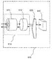
- FIG. 1is a schematic illustration of one type of a multiple-fiber collimator that is used in various embodiments of the present invention.
- FIG. 2is an enlarged view of a prism that is used in various embodiments of the present invention.
- FIG. 3illustrates alternative prism configurations that may be employed in an optical switch according to various embodiments of the present invention.
- FIGS. 4A and 4Billustrate two modes of operation of a 1 ⁇ 2 optical switch according to an embodiment of the present invention.
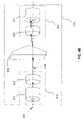
- FIGS. 5A and 5Billustrate two modes of operation of a 2 ⁇ 4 optical switch according to an embodiment of the present invention.
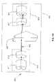
- FIGS. 6A and 6Billustrate two modes of operation of a 1 ⁇ 2 optical switch according to another embodiment of the present invention.
- FIGS. 7A and 7Billustrate two modes of operation of a 1 ⁇ 2 optical switch according to another embodiment of the present invention.
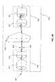
- FIG. 8illustrates various components used in a 1 ⁇ 4 optical switch according to an embodiment of the present invention.
- the present inventionincorporates multiple-fiber collimators, also referred to as multiple-port collimators, with angle tuning elements into an optical switch in innovative ways to reduce the form factor and also to reduce costs and improve the stability and performance reliability of the optical switch design.
- optical switchmay be used in various industrial applications, e.g., to provide selectable fiber routing, protection switching, system performance monitoring, etc.
- FIG. 1is a schematic illustration of a multiple-fiber collimator 100 that is used in various embodiments of the present invention.
- the multiple-fiber collimator 100has an optical axis 101 along which a collimating lens 110 and a multiple-fiber pigtail 120 are aligned.
- the multiple-fiber pigtail 120has four optical fibers 131 , 132 , 133 , 134 embedded in its body.
- the optical fibers 131 , 132 , 133 , 134extend axially through the body of the multiple-fiber pigtail 120 and are parallel to one another.
- Optical beams transmitted through the multiple-fiber collimator 100cross at a point 102 that is in close proximity to the collimating lens 110 and then diverge at angles defined by the geometry of the multiple-fiber pigtail 120 and the focal length of the collimating lens 110 .
- the centers of the collimating lens 110 and the multiple-fiber pigtail 120are aligned along the optical axis 101 of the multiple-fiber collimator 100 . Additional details of multiple-fiber collimators and the method of manufacturing them are disclosed in U.S. Pat. No. 6,454,465, entitled “Method of Making an Optical Fiber Collimating Device,” and U.S. Pat. No. 6,767,139, entitled “Six-Port Optical Package and Method of Manufacturing.” The entire contents of both of these patents are incorporated by reference herein.
- An optical switchuses the multiple-fiber collimator 100 in combination with an angle tuning element that has a unique design.
- This unique design of the angle tuning elementis based on a single-piece (monolithic) optical crystal.
- the crystalcan be considered as a multiplexer of several simple prisms and/or mirrors. It deflects an optical beam into different directions or turns multiple beams into their designated directions respectively.
- Other types of angle tuning elementsmay be used with the present invention. In general, it may be any element that is capable of deflecting an optical beam by an angle, e.g., a mirror, an optical prism, a multiplexed prism, and the like.
- angle tuning elementused in various embodiments of the present invention is a duplex prism or a roof prism, illustrated in FIG. 2 . If an optical beam arrives at the upper surface of this prism, the prism will deflect the optical beam downwards by an angle ⁇ . If an optical beam arrives at the lower surface of this prism, the prism will deflect the optical beam upwards by an angle ⁇ .
- the angles ⁇ and ⁇can be designed to be the same or different angles depending on the application. If the angles ⁇ and ⁇ are equal, the prism is considered to be symmetrical.
- FIG. 3illustrates alternative configurations of a duplex or roof prism.
- FIGS. 4A and 4Billustrate a 1 ⁇ 2 optical switch 400 according to an embodiment of the present invention.
- the optical switch 400includes an input collimator 410 , an output collimator 420 , and a roof prism 430 functioning as an angle tuning element.
- the input collimator 410is a single-fiber collimator and includes a pigtail section 411 and a collimating lens 412 .
- the output collimator 420is a dual-fiber collimator and includes a pigtail section 421 and a collimating lens 422 .
- the input collimator 410 and the output collimator 420are coaxially arranged along the optical axis 401 of the optical switch 400 .
- the roof prism 430is movable into two positions by an actuator mechanism (not shown), which may be any conventional actuator, including a mechanical actuator, electromechanical actuator, magnetic actuator, piezoelectric actuator, and the like.
- FIG. 4Aillustrates the optical switch 400 operating in a first mode.
- the roof prism 430is actuated into a down position so that an optical beam transmitted through the input collimator 410 is deflected by the upper part of the roof prism 430 into one of the two fibers embedded in the pigtail section 421 .
- FIG. 4Billustrates the optical switch 400 operating in a second mode. In the second mode, the roof prism 430 is actuated into an up position so that an optical beam transmitted through the input collimator 410 is deflected by the lower part of the roof prism 430 into the other fiber embedded in the pigtail section 421 .
- FIGS. 5A and 5Billustrate a 2 ⁇ 4 optical switch 500 according to an embodiment of the present invention.
- the optical switch 500includes an input collimator 510 , an output collimator 520 , and a roof prism 530 functioning as an angle tuning element.
- the input collimator 510is a dual-fiber collimator and includes a pigtail section 511 and a collimating lens 512 .
- the output collimator 520is a four-fiber collimator and includes a pigtail section 521 and a collimating lens 522 .
- the input collimator 510 and the output collimator 520are coaxially arranged along the optical axis 501 of the optical switch 500 .
- the roof prism 530is movable into two positions by an actuator mechanism (not shown), which may be any conventional actuator, including a mechanical actuator, electromechanical actuator, magnetic actuator, piezoelectric actuator, and the like.
- FIG. 5Aillustrates the optical switch 500 operating in a first mode.
- the roof prism 530is actuated into a down position so that the optical beams 502 , 503 transmitted through the input collimator 510 are deflected by the upper part of the roof prism 530 into two of the four fibers embedded in the pigtail section 521 .
- FIG. 5Billustrates the optical switch 500 operating in a second mode.
- the roof prism 530is actuated into an up position so that the optical beams 502 , 503 transmitted through the input collimator 510 are deflected by the lower part of the roof prism 530 into the other two fibers embedded in the pigtail section 521 .
- Embodiments of the optical switch illustrated in FIGS. 5A , 5 B, 6 A and 6 Bincorporates the highly integrated multiple-port, multiple-fiber collimators with multiplexed angle tuning elements so that they are coaxially arranged along the optical axis of the optical switch.
- an ultra compact opto-mechanical structurethat is much more simple and stable relative to the prior art designs is provided.
- FIGS. 6A and 6Billustrate a 1 ⁇ 2 optical switch according to another embodiment of the present invention.
- input and output ports of the optical switch 600are provided on the same side of the optical switch 600 .
- This designalso provides improved stability and performance reliability because it uses less components.
- a three-fiber collimatorcan serve as the input/output ports of a 1 ⁇ 2 optical switch, but in the optical switch 600 , a four-fiber collimator 610 is provided because it is manufactured in higher volumes and is thus more readily available.
- the four-fiber collimator 610includes a pigtail section 611 and a collimating lens 612 .
- the optical switch 600further includes a roof prism 630 and a mirror 640 .
- the roof prism 630is positioned in the path of the optical beam reflected by the mirror 640 , but not in the path of the optical beam between the output of the collimator 610 and the mirror 640 .
- the roof prism 630may be positioned in the path of the optical beam between the output of the collimator 610 and the mirror 640 , but not in the path of the optical beam reflected by the mirror 640 .
- the roof prism 630is movable into two positions by an actuator mechanism (not shown), which may be any conventional actuator, including a mechanical actuator, electromechanical actuator, magnetic actuator, piezoelectric actuator, and the like.
- FIG. 6Aillustrates the optical switch 600 operating in a first mode.
- the roof prism 630is actuated into a down position so that the optical beam transmitted through a first one of fibers of the four-fiber collimator 610 and the collimating lens 612 and reflected by the mirror 640 is deflected by the upper part of the roof prism 630 into a second one of the four fibers embedded in the pigtail section 611 .
- FIG. 6Billustrates the optical switch 600 operating in a second mode.
- the roof prism 630is actuated into an up position so that the optical beam transmitted through a first one of fibers of the four-fiber collimator 610 and the collimating lens 612 and reflected by the mirror 640 is deflected by the lower part of the roof prism 630 into a third one of the four fibers embedded in the pigtail section 611 .
- a fourth one of the four fibers embedded in the pigtail section 611is not used.
- the roof prism 630 and the mirror 640can be replaced by a monolithic optical element 730 , as shown in FIGS. 7A and 7B .
- the monolithic optical element 730has a roof prism substrate with the two front angular surfaces having anti-reflective coating and the rear surface 731 having a high-reflective coating.
- FIG. 7Aillustrates the optical switch 700 operating in a first mode.
- the monolithic optical element 730is actuated into a down position so that the optical beam transmitted through a first one of fibers of the four-fiber collimator 610 and the collimating lens 612 is transmitted through the front upper surface of the monolithic optical element 730 and reflected by the rear surface of the monolithic optical element 730 .
- the reflected optical beamis then deflected by the upper part of the monolithic optical element 730 into a second one of the four fibers embedded in the pigtail section 611 .
- FIG. 7Billustrates the optical switch 600 operating in a second mode.
- the monolithic optical element 730is actuated into an up position so that the optical beam transmitted through a first one of fibers of the four-fiber collimator 610 and the collimating lens 612 is transmitted through the front lower surface of the monolithic optical element 730 and reflected by the rear surface of the monolithic optical element 730 .
- the reflected optical beamis then deflected by the lower part of the monolithic optical element 730 into a third one of the four fibers embedded in the pigtail section 611 .
- a fourth one of the four fibers embedded in the pigtail section 611is not used.
- FIG. 8is a schematic illustration of a 1 ⁇ 4 optical switch 800 according to an embodiment of the present invention.
- the optical switch 800includes an input collimator including an input fiber 811 and an input collimating lens 812 , an output collimator including a set of output fibers 821 and an output collimating lens 822 , and a pair of prisms 830 , 840 .
- the prisms 830 , 840provide two stages of angle tuning. In the first stage, the prism 830 deflects the optical beam upwards or downwards by an angle depending on its position. In the second stage, the prism 840 , depending on its position, may further deflect the optical beam that has been deflected by the prism 830 .
- a set of four deflected optical beams 851 , 852 , 853 , 854are shown in FIG. 8 .
- the optical beam 851represents an optical beam that is deflected upwards by the prism 830 and then further deflected by the prism 840 .
- the optical beam 852represents an optical beam that is deflected upwards by the prism 830 and not further deflected by the prism 840 .
- the optical beam 853represents an optical beam that is deflected downwards by the prism 830 and then further deflected by the prism 840 .
- the optical beam 854represents an optical beam that is deflected downwards by the prism 830 and not further deflected by the prism 840 .
- the prisms 830 , 840are moved by an actuator mechanism (not shown), which may be any conventional actuator, including a mechanical actuator, electromechanical actuator, magnetic actuator, piezoelectric actuator, and the like.
- the prism 830is movable into an up position where it deflects the incoming optical beam upwards and a down position where it deflects the incoming optical beam downwards.
- the prism 840is also movable into two positions. In the first position, the prism 840 is in the path of the optical beam deflected by the prism 830 . In the second position, the prism 840 is moved completely out of the path of the optical beam deflected by the prism 830 .
Landscapes
- Physics & Mathematics (AREA)
- General Physics & Mathematics (AREA)
- Optics & Photonics (AREA)
- Mechanical Light Control Or Optical Switches (AREA)
Abstract
Description
Claims (14)
Priority Applications (1)
| Application Number | Priority Date | Filing Date | Title |
|---|---|---|---|
| US11/875,533US7603006B2 (en) | 2006-03-15 | 2007-10-19 | Optical switch having angle tuning elements and multiple-fiber collimators |
Applications Claiming Priority (2)
| Application Number | Priority Date | Filing Date | Title |
|---|---|---|---|
| US11/376,051US7286730B2 (en) | 2006-03-15 | 2006-03-15 | Optical switch having angle tuning elements and multiple-fiber collimators |
| US11/875,533US7603006B2 (en) | 2006-03-15 | 2007-10-19 | Optical switch having angle tuning elements and multiple-fiber collimators |
Related Parent Applications (1)
| Application Number | Title | Priority Date | Filing Date |
|---|---|---|---|
| US11/376,051ContinuationUS7286730B2 (en) | 2006-03-15 | 2006-03-15 | Optical switch having angle tuning elements and multiple-fiber collimators |
Publications (2)
| Publication Number | Publication Date |
|---|---|
| US20080037932A1 US20080037932A1 (en) | 2008-02-14 |
| US7603006B2true US7603006B2 (en) | 2009-10-13 |
Family
ID=38137465
Family Applications (2)
| Application Number | Title | Priority Date | Filing Date |
|---|---|---|---|
| US11/376,051ActiveUS7286730B2 (en) | 2006-03-15 | 2006-03-15 | Optical switch having angle tuning elements and multiple-fiber collimators |
| US11/875,533ActiveUS7603006B2 (en) | 2006-03-15 | 2007-10-19 | Optical switch having angle tuning elements and multiple-fiber collimators |
Family Applications Before (1)
| Application Number | Title | Priority Date | Filing Date |
|---|---|---|---|
| US11/376,051ActiveUS7286730B2 (en) | 2006-03-15 | 2006-03-15 | Optical switch having angle tuning elements and multiple-fiber collimators |
Country Status (2)
| Country | Link |
|---|---|
| US (2) | US7286730B2 (en) |
| EP (1) | EP1837687B1 (en) |
Cited By (4)
| Publication number | Priority date | Publication date | Assignee | Title |
|---|---|---|---|---|
| US20180259715A1 (en)* | 2015-09-30 | 2018-09-13 | Sony Corporation | Optical communication connector, optical communication cable, and electronic device |
| US10156677B1 (en)* | 2017-05-09 | 2018-12-18 | General Photonics Corporation | Compact optic delay lines using dual fiber collimators and roof prisms |
| US10587342B2 (en)* | 2016-12-09 | 2020-03-10 | Safran Electrical & Power | Embedded optical ring communication network for aircraft |
| US20230393445A1 (en)* | 2022-06-03 | 2023-12-07 | Ii-Vi Delaware, Inc. | Tunable optical wedge for reducing crosstalk in wavelength selective switch |
Families Citing this family (5)
| Publication number | Priority date | Publication date | Assignee | Title |
|---|---|---|---|---|
| US8150267B1 (en)* | 2007-04-18 | 2012-04-03 | Hewlett-Packard Development Company, L.P. | Optical interconnect |
| US8611742B2 (en)* | 2011-03-15 | 2013-12-17 | Capella Photonics, Inc. | Wavelength switch system using angle multiplexing optics |
| US9164242B1 (en)* | 2012-10-16 | 2015-10-20 | Alliance Fiber Optic Products, Inc. | Variable optical power splitter |
| CN104749705A (en)* | 2013-12-26 | 2015-07-01 | 上海伟钊光学科技股份有限公司 | Optical fiber sensor optical path system |
| JP6920978B2 (en)* | 2017-12-18 | 2021-08-18 | 浜松ホトニクス株式会社 | Image acquisition device and image acquisition method |
Citations (33)
| Publication number | Priority date | Publication date | Assignee | Title |
|---|---|---|---|---|
| US4244045A (en) | 1978-01-31 | 1981-01-06 | Nippon Telegraph And Telephone Public Corporation | Optical multiplexer and demultiplexer |
| JPS5957206A (en)* | 1982-09-28 | 1984-04-02 | Toshiba Corp | polarizing prism device |
| US4484793A (en)* | 1981-06-05 | 1984-11-27 | Instruments S. A. | Switching device between optical fibers |
| US4938555A (en)* | 1988-08-16 | 1990-07-03 | Sc Technology, Int. | Optical switch |
| US5028104A (en)* | 1987-05-21 | 1991-07-02 | Kaptron, Inc. | Fiber optics bypass switch |
| US5440655A (en)* | 1993-12-29 | 1995-08-08 | At&T Corp. | Optical fiber connector bypass device and method using same |
| US5647033A (en)* | 1994-05-27 | 1997-07-08 | Laughlin; Richard H. | Apparatus for switching optical signals and method of operation |
| US6009219A (en) | 1996-04-08 | 1999-12-28 | Axiom Analytical Incorporated | Optical beam switching device |
| US6014244A (en)* | 1998-06-18 | 2000-01-11 | Hewlett-Packard Company | Multi-port optical circulator utilizing imaging lens and correction optical element |
| US6075912A (en)* | 1998-03-17 | 2000-06-13 | Polaroid Corporation | Apparatus for coupling radiation beams into an optical waveguide |
| US6253007B1 (en) | 1998-07-08 | 2001-06-26 | Optical Switch Corporation | Method and apparatus for connecting optical fibers |
| US6301048B1 (en)* | 2000-05-19 | 2001-10-09 | Avanex Corporation | Tunable chromatic dispersion and dispersion slope compensator utilizing a virtually imaged phased array |
| US6353692B1 (en)* | 2000-02-17 | 2002-03-05 | Jds Uniphase Inc. | Optical switch |
| US6415067B1 (en)* | 1999-06-17 | 2002-07-02 | Jds Uniphase Inc. | N x M optical switch |
| US6493139B1 (en)* | 2001-03-16 | 2002-12-10 | Hongdu Liu | Optical switch |
| US20030043471A1 (en) | 2001-08-29 | 2003-03-06 | Belser Karl Arnold | Free-space dynamic wavelength routing systems with interleaved channels for enhanced performance |
| US6597829B2 (en) | 2001-04-27 | 2003-07-22 | Robert H. Cormack | 1xN optical fiber switch |
| US6628455B1 (en)* | 2000-03-03 | 2003-09-30 | Dicon Fiberoptics, Inc. | Multi-functional optical processor useful for fiberoptic applications |
| US6707960B2 (en)* | 2001-11-28 | 2004-03-16 | Ac Photonics, Inc. | Reflection type compact optical switch |
| US6718082B2 (en)* | 2001-12-18 | 2004-04-06 | Agiltron, Inc. | Solid-State optical wavelength switches |
| US6757101B2 (en)* | 2001-10-05 | 2004-06-29 | Agiltron, Inc. | None-mechanical dual stage optical switches |
| US6795602B2 (en)* | 1999-12-21 | 2004-09-21 | Armand P. Neukermans | Flexible, modular, compact fiber optic switch |
| US20040263990A1 (en) | 2003-03-07 | 2004-12-30 | Optoplex Corporation | Unpolarized beam splitter having polarization-independent phase difference when used as an interferometer |
| US20050036202A1 (en) | 2001-10-09 | 2005-02-17 | Gil Cohen | Wavelength selective optical switch |
| US6888971B2 (en)* | 2002-02-12 | 2005-05-03 | Oplink Communications, Inc. | Multi-port circulator |
| US20050175275A1 (en)* | 2002-07-12 | 2005-08-11 | Omron Corporation | Optical switch |
| US20060008238A1 (en) | 2003-01-31 | 2006-01-12 | Jiro Suzuki | Optical antenna |
| US20060039645A1 (en)* | 2002-07-01 | 2006-02-23 | Tomoki Uesugi | Optical switch |
| US7006287B2 (en)* | 2004-02-06 | 2006-02-28 | Industrial Technology Research Institute | Optical polarization beam combiner |
| US20060197013A1 (en) | 2005-03-01 | 2006-09-07 | Liebman Lionel D | Multi-channel fiber relays for high energy laser delivery to multi-beam ladar sensors |
| US20060209396A1 (en)* | 2003-07-14 | 2006-09-21 | Omron Corporation | Monitoring device |
| US7274510B2 (en)* | 2003-03-13 | 2007-09-25 | Finisar Corporation | Circulator and polarization beam combiner |
| US7403677B1 (en)* | 2005-05-11 | 2008-07-22 | Agiltron, Inc. | Fiberoptic reconfigurable devices with beam shaping for low-voltage operation |
Family Cites Families (5)
| Publication number | Priority date | Publication date | Assignee | Title |
|---|---|---|---|---|
| JP4323096B2 (en) | 1998-03-10 | 2009-09-02 | リモ パテントフェルヴァルトゥング ゲーエムベーハー ウント コー.カーゲー | Device for deflecting electromagnetic radiation or radiation flux in the optical spectral region |
| US6215919B1 (en)* | 1999-06-15 | 2001-04-10 | Oplink Communications, Inc. | Mechanical optical switching device |
| AU2000235006A1 (en) | 2000-02-23 | 2001-09-03 | Optical Coating Laboratory, Inc. | Optical wedge switch |
| TWI240700B (en) | 2001-07-19 | 2005-10-01 | Sumitomo Chemical Co | Ceramics dispersion liquid, method for producing the same, and hydrophilic coating agent using the same |
| US6823102B2 (en)* | 2002-07-22 | 2004-11-23 | Agiltron, Inc. | Highly stable opto-mechanic switches |
- 2006
- 2006-03-15USUS11/376,051patent/US7286730B2/enactiveActive
- 2007
- 2007-03-09EPEP07103812.9Apatent/EP1837687B1/ennot_activeNot-in-force
- 2007-10-19USUS11/875,533patent/US7603006B2/enactiveActive
Patent Citations (33)
| Publication number | Priority date | Publication date | Assignee | Title |
|---|---|---|---|---|
| US4244045A (en) | 1978-01-31 | 1981-01-06 | Nippon Telegraph And Telephone Public Corporation | Optical multiplexer and demultiplexer |
| US4484793A (en)* | 1981-06-05 | 1984-11-27 | Instruments S. A. | Switching device between optical fibers |
| JPS5957206A (en)* | 1982-09-28 | 1984-04-02 | Toshiba Corp | polarizing prism device |
| US5028104A (en)* | 1987-05-21 | 1991-07-02 | Kaptron, Inc. | Fiber optics bypass switch |
| US4938555A (en)* | 1988-08-16 | 1990-07-03 | Sc Technology, Int. | Optical switch |
| US5440655A (en)* | 1993-12-29 | 1995-08-08 | At&T Corp. | Optical fiber connector bypass device and method using same |
| US5647033A (en)* | 1994-05-27 | 1997-07-08 | Laughlin; Richard H. | Apparatus for switching optical signals and method of operation |
| US6009219A (en) | 1996-04-08 | 1999-12-28 | Axiom Analytical Incorporated | Optical beam switching device |
| US6075912A (en)* | 1998-03-17 | 2000-06-13 | Polaroid Corporation | Apparatus for coupling radiation beams into an optical waveguide |
| US6014244A (en)* | 1998-06-18 | 2000-01-11 | Hewlett-Packard Company | Multi-port optical circulator utilizing imaging lens and correction optical element |
| US6253007B1 (en) | 1998-07-08 | 2001-06-26 | Optical Switch Corporation | Method and apparatus for connecting optical fibers |
| US6415067B1 (en)* | 1999-06-17 | 2002-07-02 | Jds Uniphase Inc. | N x M optical switch |
| US6795602B2 (en)* | 1999-12-21 | 2004-09-21 | Armand P. Neukermans | Flexible, modular, compact fiber optic switch |
| US6353692B1 (en)* | 2000-02-17 | 2002-03-05 | Jds Uniphase Inc. | Optical switch |
| US6628455B1 (en)* | 2000-03-03 | 2003-09-30 | Dicon Fiberoptics, Inc. | Multi-functional optical processor useful for fiberoptic applications |
| US6301048B1 (en)* | 2000-05-19 | 2001-10-09 | Avanex Corporation | Tunable chromatic dispersion and dispersion slope compensator utilizing a virtually imaged phased array |
| US6493139B1 (en)* | 2001-03-16 | 2002-12-10 | Hongdu Liu | Optical switch |
| US6597829B2 (en) | 2001-04-27 | 2003-07-22 | Robert H. Cormack | 1xN optical fiber switch |
| US20030043471A1 (en) | 2001-08-29 | 2003-03-06 | Belser Karl Arnold | Free-space dynamic wavelength routing systems with interleaved channels for enhanced performance |
| US6757101B2 (en)* | 2001-10-05 | 2004-06-29 | Agiltron, Inc. | None-mechanical dual stage optical switches |
| US20050036202A1 (en) | 2001-10-09 | 2005-02-17 | Gil Cohen | Wavelength selective optical switch |
| US6707960B2 (en)* | 2001-11-28 | 2004-03-16 | Ac Photonics, Inc. | Reflection type compact optical switch |
| US6718082B2 (en)* | 2001-12-18 | 2004-04-06 | Agiltron, Inc. | Solid-State optical wavelength switches |
| US6888971B2 (en)* | 2002-02-12 | 2005-05-03 | Oplink Communications, Inc. | Multi-port circulator |
| US20060039645A1 (en)* | 2002-07-01 | 2006-02-23 | Tomoki Uesugi | Optical switch |
| US20050175275A1 (en)* | 2002-07-12 | 2005-08-11 | Omron Corporation | Optical switch |
| US20060008238A1 (en) | 2003-01-31 | 2006-01-12 | Jiro Suzuki | Optical antenna |
| US20040263990A1 (en) | 2003-03-07 | 2004-12-30 | Optoplex Corporation | Unpolarized beam splitter having polarization-independent phase difference when used as an interferometer |
| US7274510B2 (en)* | 2003-03-13 | 2007-09-25 | Finisar Corporation | Circulator and polarization beam combiner |
| US20060209396A1 (en)* | 2003-07-14 | 2006-09-21 | Omron Corporation | Monitoring device |
| US7006287B2 (en)* | 2004-02-06 | 2006-02-28 | Industrial Technology Research Institute | Optical polarization beam combiner |
| US20060197013A1 (en) | 2005-03-01 | 2006-09-07 | Liebman Lionel D | Multi-channel fiber relays for high energy laser delivery to multi-beam ladar sensors |
| US7403677B1 (en)* | 2005-05-11 | 2008-07-22 | Agiltron, Inc. | Fiberoptic reconfigurable devices with beam shaping for low-voltage operation |
Cited By (7)
| Publication number | Priority date | Publication date | Assignee | Title |
|---|---|---|---|---|
| US20180259715A1 (en)* | 2015-09-30 | 2018-09-13 | Sony Corporation | Optical communication connector, optical communication cable, and electronic device |
| US10502902B2 (en)* | 2015-09-30 | 2019-12-10 | Sony Corporation | Optical communication connector, optical communication cable, and electronic device |
| US10983283B2 (en) | 2015-09-30 | 2021-04-20 | Sony Corporation | Optical communication connector, optical communication cable, and electronic device |
| US10587342B2 (en)* | 2016-12-09 | 2020-03-10 | Safran Electrical & Power | Embedded optical ring communication network for aircraft |
| US10156677B1 (en)* | 2017-05-09 | 2018-12-18 | General Photonics Corporation | Compact optic delay lines using dual fiber collimators and roof prisms |
| US20230393445A1 (en)* | 2022-06-03 | 2023-12-07 | Ii-Vi Delaware, Inc. | Tunable optical wedge for reducing crosstalk in wavelength selective switch |
| US12345998B2 (en)* | 2022-06-03 | 2025-07-01 | Ii-Vi Delaware, Inc. | Tunable optical wedge for reducing crosstalk in wavelength selective switch |
Also Published As
| Publication number | Publication date |
|---|---|
| EP1837687A1 (en) | 2007-09-26 |
| US20080037932A1 (en) | 2008-02-14 |
| US20070217735A1 (en) | 2007-09-20 |
| US7286730B2 (en) | 2007-10-23 |
| EP1837687B1 (en) | 2014-05-14 |
Similar Documents
| Publication | Publication Date | Title |
|---|---|---|
| US7603006B2 (en) | Optical switch having angle tuning elements and multiple-fiber collimators | |
| US6330102B1 (en) | Apparatus and method for 2-dimensional steered-beam NxM optical switch using single-axis mirror arrays and relay optics | |
| US6163643A (en) | Micro-mechanical variable optical attenuator | |
| US6477289B1 (en) | Optical wedge switch | |
| US6404969B1 (en) | Optical switching and attenuation systems and methods therefor | |
| US6647173B2 (en) | Optical switch with a moveable optical component | |
| JP2005049742A (en) | Variable optical attenuator | |
| JP2008224824A (en) | Wavelength selection switches | |
| US6845187B1 (en) | Linear optical beam translator for optical routing | |
| EP1102104A2 (en) | Optical switch | |
| CA2334833C (en) | Optical switch | |
| US6707960B2 (en) | Reflection type compact optical switch | |
| US7177498B2 (en) | Two-by-two optical routing element using two-position MEMS mirrors | |
| US6587614B2 (en) | Optical switch | |
| US7062120B2 (en) | Optical device and movable reflector | |
| US6625344B2 (en) | Optical switch | |
| US6970615B1 (en) | Compact high-stability optical switches | |
| US7221818B2 (en) | Optical switch | |
| US6731835B2 (en) | Optic switch | |
| EP1531350B1 (en) | Optical device for varying the power of light having a movable reflector | |
| WO2001063338A1 (en) | Optical wedge switch | |
| JP2008129567A (en) | Optical device | |
| US20030202739A1 (en) | Optical switch unit and a method therefore | |
| JP2005070710A (en) | Optical attenuator | |
| WO2001029599A1 (en) | Mems based 1xn fiber optics switch |
Legal Events
| Date | Code | Title | Description |
|---|---|---|---|
| FEPP | Fee payment procedure | Free format text:PAYOR NUMBER ASSIGNED (ORIGINAL EVENT CODE: ASPN); ENTITY STATUS OF PATENT OWNER: LARGE ENTITY | |
| STCF | Information on status: patent grant | Free format text:PATENTED CASE | |
| AS | Assignment | Owner name:WELLS FARGO CAPITAL FINANCE, INC., AS AGENT, CALIF Free format text:PATENT SECURITY AGREEMENT;ASSIGNOR:OCLARO (NORTH AMERICA), INC.;REEL/FRAME:028540/0769 Effective date:20110726 | |
| FPAY | Fee payment | Year of fee payment:4 | |
| AS | Assignment | Owner name:AVANEX CORPORATION, CALIFORNIA Free format text:ASSIGNMENT OF ASSIGNORS INTEREST;ASSIGNORS:CAI, MING;WU, XUEHUA;BARBAROSSA, GIOVANNI;SIGNING DATES FROM 20060304 TO 20060312;REEL/FRAME:032861/0382 | |
| AS | Assignment | Owner name:OCLARO (NORTH AMERICA), INC., CALIFORNIA Free format text:CHANGE OF NAME;ASSIGNOR:AVANEX CORPORATION;REEL/FRAME:032889/0372 Effective date:20090707 | |
| AS | Assignment | Owner name:II-VI INCORPORATED, PENNSYLVANIA Free format text:ASSIGNMENT OF ASSIGNORS INTEREST;ASSIGNORS:OCLARO TECHNOLOGY LIMITED;OCLARO, INC.;OCLARO (NORTH AMERICA), INC.;AND OTHERS;REEL/FRAME:032908/0544 Effective date:20131101 | |
| AS | Assignment | Owner name:OCLARO, INC., CALIFORNIA Free format text:RELEASE OF SECURITY INTEREST;ASSIGNOR:WELLS FARGO CAPITAL FINANCE, LLC;REEL/FRAME:032982/0222 Effective date:20131101 Owner name:OCLARO TECHNOLOGY LIMITED, CALIFORNIA Free format text:RELEASE OF SECURITY INTEREST;ASSIGNOR:WELLS FARGO CAPITAL FINANCE, LLC;REEL/FRAME:032982/0222 Effective date:20131101 | |
| FPAY | Fee payment | Year of fee payment:8 | |
| AS | Assignment | Owner name:BANK OF AMERICA, N.A., AS ADMINISTRATIVE AGENT, NO Free format text:NOTICE OF GRANT OF SECURITY INTEREST IN PATENTS;ASSIGNORS:II-VI INCORPORATED;MARLOW INDUSTRIES, INC.;EPIWORKS, INC.;AND OTHERS;REEL/FRAME:050484/0204 Effective date:20190924 Owner name:BANK OF AMERICA, N.A., AS ADMINISTRATIVE AGENT, NORTH CAROLINA Free format text:NOTICE OF GRANT OF SECURITY INTEREST IN PATENTS;ASSIGNORS:II-VI INCORPORATED;MARLOW INDUSTRIES, INC.;EPIWORKS, INC.;AND OTHERS;REEL/FRAME:050484/0204 Effective date:20190924 | |
| AS | Assignment | Owner name:II-VI DELAWARE, INC., DELAWARE Free format text:ASSIGNMENT OF ASSIGNORS INTEREST;ASSIGNOR:II-VI INCORPORATED;REEL/FRAME:051210/0411 Effective date:20191202 | |
| MAFP | Maintenance fee payment | Free format text:PAYMENT OF MAINTENANCE FEE, 12TH YEAR, LARGE ENTITY (ORIGINAL EVENT CODE: M1553); ENTITY STATUS OF PATENT OWNER: LARGE ENTITY Year of fee payment:12 | |
| AS | Assignment | Owner name:JPMORGAN CHASE BANK, N.A., AS COLLATERAL AGENT, NEW YORK Free format text:SECURITY INTEREST;ASSIGNORS:II-VI INCORPORATED;II-VI DELAWARE, INC.;M CUBED TECHNOLOGIES, INC.;AND OTHERS;REEL/FRAME:060562/0254 Effective date:20220701 | |
| AS | Assignment | Owner name:PHOTOP TECHNOLOGIES, INC., CALIFORNIA Free format text:PATENT RELEASE AND REASSIGNMENT;ASSIGNOR:BANK OF AMERICA, N.A., AS ADMINISTRATIVE AGENT;REEL/FRAME:060574/0001 Effective date:20220701 Owner name:II-VI OPTOELECTRONIC DEVICES, INC., NEW JERSEY Free format text:PATENT RELEASE AND REASSIGNMENT;ASSIGNOR:BANK OF AMERICA, N.A., AS ADMINISTRATIVE AGENT;REEL/FRAME:060574/0001 Effective date:20220701 Owner name:II-VI DELAWARE, INC., PENNSYLVANIA Free format text:PATENT RELEASE AND REASSIGNMENT;ASSIGNOR:BANK OF AMERICA, N.A., AS ADMINISTRATIVE AGENT;REEL/FRAME:060574/0001 Effective date:20220701 Owner name:II-VI PHOTONICS (US), INC., MASSACHUSETTS Free format text:PATENT RELEASE AND REASSIGNMENT;ASSIGNOR:BANK OF AMERICA, N.A., AS ADMINISTRATIVE AGENT;REEL/FRAME:060574/0001 Effective date:20220701 Owner name:M CUBED TECHNOLOGIES, INC., CONNECTICUT Free format text:PATENT RELEASE AND REASSIGNMENT;ASSIGNOR:BANK OF AMERICA, N.A., AS ADMINISTRATIVE AGENT;REEL/FRAME:060574/0001 Effective date:20220701 Owner name:II-VI OPTICAL SYSTEMS, INC., CALIFORNIA Free format text:PATENT RELEASE AND REASSIGNMENT;ASSIGNOR:BANK OF AMERICA, N.A., AS ADMINISTRATIVE AGENT;REEL/FRAME:060574/0001 Effective date:20220701 Owner name:FINISAR CORPORATION, CALIFORNIA Free format text:PATENT RELEASE AND REASSIGNMENT;ASSIGNOR:BANK OF AMERICA, N.A., AS ADMINISTRATIVE AGENT;REEL/FRAME:060574/0001 Effective date:20220701 Owner name:OPTIUM CORPORATION, CALIFORNIA Free format text:PATENT RELEASE AND REASSIGNMENT;ASSIGNOR:BANK OF AMERICA, N.A., AS ADMINISTRATIVE AGENT;REEL/FRAME:060574/0001 Effective date:20220701 Owner name:COADNA PHOTONICS, INC., PENNSYLVANIA Free format text:PATENT RELEASE AND REASSIGNMENT;ASSIGNOR:BANK OF AMERICA, N.A., AS ADMINISTRATIVE AGENT;REEL/FRAME:060574/0001 Effective date:20220701 Owner name:KAILIGHT PHOTONICS, INC., CALIFORNIA Free format text:PATENT RELEASE AND REASSIGNMENT;ASSIGNOR:BANK OF AMERICA, N.A., AS ADMINISTRATIVE AGENT;REEL/FRAME:060574/0001 Effective date:20220701 Owner name:LIGHTSMYTH TECHNOLOGIES, INC., OREGON Free format text:PATENT RELEASE AND REASSIGNMENT;ASSIGNOR:BANK OF AMERICA, N.A., AS ADMINISTRATIVE AGENT;REEL/FRAME:060574/0001 Effective date:20220701 Owner name:EPIWORKS, INC., ILLINOIS Free format text:PATENT RELEASE AND REASSIGNMENT;ASSIGNOR:BANK OF AMERICA, N.A., AS ADMINISTRATIVE AGENT;REEL/FRAME:060574/0001 Effective date:20220701 Owner name:MARLOW INDUSTRIES, INC., TEXAS Free format text:PATENT RELEASE AND REASSIGNMENT;ASSIGNOR:BANK OF AMERICA, N.A., AS ADMINISTRATIVE AGENT;REEL/FRAME:060574/0001 Effective date:20220701 Owner name:II-VI INCORPORATED, PENNSYLVANIA Free format text:PATENT RELEASE AND REASSIGNMENT;ASSIGNOR:BANK OF AMERICA, N.A., AS ADMINISTRATIVE AGENT;REEL/FRAME:060574/0001 Effective date:20220701 |