US7602857B2 - Digital transmitter - Google Patents
Digital transmitterDownload PDFInfo
- Publication number
- US7602857B2 US7602857B2US11/514,577US51457706AUS7602857B2US 7602857 B2US7602857 B2US 7602857B2US 51457706 AUS51457706 AUS 51457706AUS 7602857 B2US7602857 B2US 7602857B2
- Authority
- US
- United States
- Prior art keywords
- signal
- component
- operable
- circuit
- transmitter circuit
- Prior art date
- Legal status (The legal status is an assumption and is not a legal conclusion. Google has not performed a legal analysis and makes no representation as to the accuracy of the status listed.)
- Expired - Fee Related, expires
Links
- 230000007704transitionEffects0.000claimsabstractdescription22
- 230000006870functionEffects0.000claimsdescription12
- 239000004065semiconductorSubstances0.000claimsdescription7
- 230000005540biological transmissionEffects0.000abstractdescription14
- 238000012549trainingMethods0.000abstractdescription5
- 230000003044adaptive effectEffects0.000abstractdescription2
- 230000004044responseEffects0.000description19
- 230000011664signalingEffects0.000description13
- 230000001419dependent effectEffects0.000description7
- 238000013461designMethods0.000description7
- 229920005994diacetyl cellulosePolymers0.000description7
- 230000002238attenuated effectEffects0.000description6
- 238000005516engineering processMethods0.000description6
- 238000004891communicationMethods0.000description5
- 238000000034methodMethods0.000description5
- 230000003111delayed effectEffects0.000description4
- 238000001514detection methodMethods0.000description4
- 230000002500effect on skinEffects0.000description4
- 230000000694effectsEffects0.000description4
- 238000013459approachMethods0.000description3
- 230000003071parasitic effectEffects0.000description3
- 230000002093peripheral effectEffects0.000description3
- 230000008569processEffects0.000description3
- 230000008901benefitEffects0.000description2
- 238000010586diagramMethods0.000description2
- 230000003287optical effectEffects0.000description2
- 230000035945sensitivityEffects0.000description2
- RYGMFSIKBFXOCR-UHFFFAOYSA-NCopperChemical compound[Cu]RYGMFSIKBFXOCR-UHFFFAOYSA-N0.000description1
- 229910052802copperInorganic materials0.000description1
- 239000010949copperSubstances0.000description1
- 238000012937correctionMethods0.000description1
- 238000001914filtrationMethods0.000description1
- 230000002452interceptive effectEffects0.000description1
- 238000001459lithographyMethods0.000description1
- 238000005259measurementMethods0.000description1
- 230000037452primingEffects0.000description1
- 230000009467reductionEffects0.000description1
- 230000008672reprogrammingEffects0.000description1
- 238000005070samplingMethods0.000description1
- 230000001360synchronised effectEffects0.000description1
Images


Classifications
- H—ELECTRICITY
- H04—ELECTRIC COMMUNICATION TECHNIQUE
- H04L—TRANSMISSION OF DIGITAL INFORMATION, e.g. TELEGRAPHIC COMMUNICATION
- H04L25/00—Baseband systems
- H04L25/02—Details ; arrangements for supplying electrical power along data transmission lines
- H04L25/03—Shaping networks in transmitter or receiver, e.g. adaptive shaping networks
- H04L25/03006—Arrangements for removing intersymbol interference
- H04L25/03012—Arrangements for removing intersymbol interference operating in the time domain
- H04L25/03019—Arrangements for removing intersymbol interference operating in the time domain adaptive, i.e. capable of adjustment during data reception
- H—ELECTRICITY
- H04—ELECTRIC COMMUNICATION TECHNIQUE
- H04B—TRANSMISSION
- H04B1/00—Details of transmission systems, not covered by a single one of groups H04B3/00 - H04B13/00; Details of transmission systems not characterised by the medium used for transmission
- H04B1/02—Transmitters
- H04B1/04—Circuits
- H04B1/0483—Transmitters with multiple parallel paths
- H—ELECTRICITY
- H04—ELECTRIC COMMUNICATION TECHNIQUE
- H04B—TRANSMISSION
- H04B1/00—Details of transmission systems, not covered by a single one of groups H04B3/00 - H04B13/00; Details of transmission systems not characterised by the medium used for transmission
- H04B1/06—Receivers
- H04B1/10—Means associated with receiver for limiting or suppressing noise or interference
- H04B1/1081—Reduction of multipath noise
- H—ELECTRICITY
- H04—ELECTRIC COMMUNICATION TECHNIQUE
- H04B—TRANSMISSION
- H04B1/00—Details of transmission systems, not covered by a single one of groups H04B3/00 - H04B13/00; Details of transmission systems not characterised by the medium used for transmission
- H04B1/06—Receivers
- H04B1/16—Circuits
- H—ELECTRICITY
- H04—ELECTRIC COMMUNICATION TECHNIQUE
- H04B—TRANSMISSION
- H04B3/00—Line transmission systems
- H04B3/02—Details
- H04B3/04—Control of transmission; Equalising
- H—ELECTRICITY
- H04—ELECTRIC COMMUNICATION TECHNIQUE
- H04L—TRANSMISSION OF DIGITAL INFORMATION, e.g. TELEGRAPHIC COMMUNICATION
- H04L1/00—Arrangements for detecting or preventing errors in the information received
- H04L1/004—Arrangements for detecting or preventing errors in the information received by using forward error control
- H04L1/0041—Arrangements at the transmitter end
- H04L1/0042—Encoding specially adapted to other signal generation operation, e.g. in order to reduce transmit distortions, jitter, or to improve signal shape
- H—ELECTRICITY
- H04—ELECTRIC COMMUNICATION TECHNIQUE
- H04L—TRANSMISSION OF DIGITAL INFORMATION, e.g. TELEGRAPHIC COMMUNICATION
- H04L25/00—Baseband systems
- H04L25/02—Details ; arrangements for supplying electrical power along data transmission lines
- H04L25/03—Shaping networks in transmitter or receiver, e.g. adaptive shaping networks
- H04L25/03006—Arrangements for removing intersymbol interference
- H04L25/03012—Arrangements for removing intersymbol interference operating in the time domain
- H04L25/03019—Arrangements for removing intersymbol interference operating in the time domain adaptive, i.e. capable of adjustment during data reception
- H04L25/03025—Arrangements for removing intersymbol interference operating in the time domain adaptive, i.e. capable of adjustment during data reception using a two-tap delay line
- H—ELECTRICITY
- H04—ELECTRIC COMMUNICATION TECHNIQUE
- H04L—TRANSMISSION OF DIGITAL INFORMATION, e.g. TELEGRAPHIC COMMUNICATION
- H04L25/00—Baseband systems
- H04L25/02—Details ; arrangements for supplying electrical power along data transmission lines
- H04L25/03—Shaping networks in transmitter or receiver, e.g. adaptive shaping networks
- H04L25/03006—Arrangements for removing intersymbol interference
- H04L25/03343—Arrangements at the transmitter end
- H—ELECTRICITY
- H04—ELECTRIC COMMUNICATION TECHNIQUE
- H04L—TRANSMISSION OF DIGITAL INFORMATION, e.g. TELEGRAPHIC COMMUNICATION
- H04L25/00—Baseband systems
- H04L25/02—Details ; arrangements for supplying electrical power along data transmission lines
- H04L25/03—Shaping networks in transmitter or receiver, e.g. adaptive shaping networks
- H04L25/03878—Line equalisers; line build-out devices
- H04L25/03885—Line equalisers; line build-out devices adaptive
- H—ELECTRICITY
- H04—ELECTRIC COMMUNICATION TECHNIQUE
- H04L—TRANSMISSION OF DIGITAL INFORMATION, e.g. TELEGRAPHIC COMMUNICATION
- H04L27/00—Modulated-carrier systems
- H04L27/01—Equalisers
- H—ELECTRICITY
- H04—ELECTRIC COMMUNICATION TECHNIQUE
- H04L—TRANSMISSION OF DIGITAL INFORMATION, e.g. TELEGRAPHIC COMMUNICATION
- H04L25/00—Baseband systems
- H04L25/02—Details ; arrangements for supplying electrical power along data transmission lines
- H04L25/0264—Arrangements for coupling to transmission lines
- H04L25/0272—Arrangements for coupling to multiple lines, e.g. for differential transmission
- H—ELECTRICITY
- H04—ELECTRIC COMMUNICATION TECHNIQUE
- H04L—TRANSMISSION OF DIGITAL INFORMATION, e.g. TELEGRAPHIC COMMUNICATION
- H04L25/00—Baseband systems
- H04L25/02—Details ; arrangements for supplying electrical power along data transmission lines
- H04L25/0264—Arrangements for coupling to transmission lines
- H04L25/028—Arrangements specific to the transmitter end
- H04L25/0282—Provision for current-mode coupling
Definitions
- the present inventionenables equalizers which can be implemented as digital filters operating at acceptable clock speeds. For example, a three gigabit per second (Gbps) system can be implemented using 400 Mbps circuitry.
- the inventionhas particular application to nonmodulated, high data rate, binary or multilevel systems as found locally within a data processor cabinet or on a local area network.
- a digital transmittercomprises an equalizer which emphasizes transition signal levels relative to repeated signal levels.
- a novel equalizergenerates signal levels as a logical function of bit history to emphasize transition signal levels.
- Preferred implementationsdefine the logical function of bit history in a look up table.
- the equalizerconverts an input signal, having discrete signal levels at an input data rate, to an output signal having a greater number of discrete signal levels at the input data rate.
- the equalizergenerates transmitted signal levels based on time since last signal transition. A particularly simple implementation is based on whether a current bit is equal to an immediately previous bit.
- the clock rates of circuitrycan be reduced by multiplexing outputs of parallel logic circuits operating on different multiple bit inputs to generate the signal levels.
- the level of equalization in the transmittercan be modified as a function of signals detected at the receiver.
- FIG. 1illustrates a digital communication system embodying in the present invention.
- FIGS. 2A and 2Billustrate a sample binary pulse train and the resultant frequency dependent attenuation caused by a transmission line.
- FIGS. 3A and 3Billustrate the resistance and attenuation curves for one meter of 30AWG, 100 ohm twisted pair transmission line
- FIGS. 3C and 3Dillustrate the resistance and attenuation curves for one meter of 5 mil 0.5 oz 50 ohm strip guide.
- FIG. 4Aillustrates respective plus and minus signals in a differential system and the reduced data eye due to attenuation;
- FIG. 4Billustrates trailing edge jitter;
- FIG. 4Cillustrates the data eye with equalization.
- FIGS. 5A and 5Billustrate impulse response and frequency response of an equalizing filter embodying the invention
- FIGS. 5C and 5Dillustrate an example input sequence and output sequence from the equalizer.
- FIG. 6Aillustrates the frequency response of an equalization filter embodying the invention
- FIG. 6Billustrates transmission line attenuation
- FIG. 6Cillustrates the combination of equalization and line attenuation.
- FIG. 7Aillustrates an equalized transmitter signal based on the input signal of FIG. 2A
- FIG. 7Billustrates the signal at the receiver resulting from the signal of FIG. 7A to be compared to FIG. 2B without equalization.
- FIG. 8illustrates one embodiment of an equalizer of the present invention including an FIR filter and digital-to-analog converter.
- FIG. 9illustrates a transition filter for use in a preferred embodiment of the invention.
- FIG. 10illustrates a two tap transition filter embodying the invention.
- FIGS. 11A and 111Billustrate a digital to analog converter for use in the present invention.
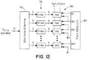
- FIG. 12illustrates a preferred multiplexed embodiment of the invention.
- FIG. 13illustrates CPU to memory and peripheral connections and a hub chip embodying the invention.
- a system embodying the inventioncan achieve a four Gbps signaling rate using 0.5 ⁇ m CMOS circuits by controlling and compensating for characteristics of the transmission medium, by cancelling timing skew, and through careful management of time and voltage noise.
- FIG. 1shows one channel of high-speed signaling system embodying the invention.
- a transmitter module 22accepts 8-bit parallel data at 400 MHz. Each byte is coded into 10 bits for band-limiting and forward error correction and transmitted up to 3 m across a single differential transmission line. The transmitter pre-emphasizes the signal to compensate for expected line characteristics. The lossy transmission line as well as package and connector parasitics attenuate and distort the received waveform, and it is further corrupted by noise coupled from adjacent lines and the power supply.
- the receiver 24accepts this noisy, distorted signal and its own 400 MHz clock. The receiver generates 4 GHz timing signals aligned to the received data, samples the noisy signal, decodes the signal, and produces synchronous 8-bit data out.
- a network based on 400 MBytes/s serial channelsfor example, has several times the bandwidth of a 133 MBytes/s PCI-bus that requires about 80 lines. Also, depending on its topology, the network permits several simultaneous transfers to take place at full rate. A group of eight parallel channels would provide sufficient bandwidth (3.2 GBytes/s) for the CPU to memory connection of today's fastest processors. For modest distances (up to 30 m with 18AWG wire), high-speed electrical signaling is an attractive alternative to optical communication in terms of cost, power, and board area for peripheral connection and building-sized local-area networks.
- Skin-effect resistancecauses the attenuation of a conventional transmission line to increase with frequency.
- a broadband signalas typically used in digital systems, the superposition of unattenuated low-frequency signal components with attenuated high-frequency signal components causes intersymbol interference that degrades noise margins and reduces the maximum frequency at which the system can operate.
- FIGS. 2A and Bshow a 4 Gb/s signal ( FIG. 2A ) and the simulated result of passing this signal across 3 m of 24AWG twisted pair ( FIG. 2B ).
- the highest frequency of interest (2 GHz)is attenuated by ⁇ 7.6 dB (42%).
- the unattenuated low-frequency component of the signalcauses the isolated high-frequency pulse to barely reach the midpoint of the signal swing giving no eye opening in a differential system and very little probability of correct detection.
- the problem hereis not the magnitude of the attenuation, but rather the interference caused by the frequency-dependent nature of the attenuation.
- the high-frequency pulsehas sufficient amplitude at the receiver for proper detection. It is the offset of the pulse from the receiver threshold by low-frequency interference that causes the problem. Later, we will see how using a transmitter equalizer to preemphasize the high-frequency components of the signal eliminates this problem. However, first we will characterize the nature of this attenuation in more detail.
- the skin effectbegins increasing resistance at 267 KHz and results in an attenuation to 56% of the original magnitude ( ⁇ 5 dB) per meter of cable at our operating frequency of 2 GHz corresponding to a bit rate of 4 Gb/s.
- FIG. 4A-CThe effect of frequency dependent attenuation is graphically illustrated in the eye-diagrams of FIG. 4A-C .
- a high-frequency attenuation factor of Areduces the height of the eye opening to 2A-1 with the eye completely disappearing at A ⁇ 0.5. This height is the amount of effective signal swing available to tolerate other noise sources such as receiver offset, receiver sensitivity, crosstalk, reflections of previous bits, and coupled supply noise. Because the waveforms cross the receiver threshold offset from the center of the signal swing, the width of the eye is also reduced.
- FIG. 4Bthe leading edge of the attenuated pulse crosses the threshold at the normal time. The trailing edge, however, is advanced by t j . This data-dependent jitter causes greater sensitivity to skew and jitter in the signal or sampling clock and may introduce noise into the timing loop.
- the waveform of FIG. 4Cillustrates the situation when we equalize the signal by attenuating the DC and low frequency components so all components are attenuated by a factor of A.
- the height of the eye openingis A, considerably larger than 2A-1, especially for large attenuations.
- the width of the eyeis a full bit-cell giving better tolerance of timing skew and jitter.
- Equalizationeliminates the problem of frequency-dependent attenuation by filtering the transmitted or received waveform so the concatenation of the equalizing filter and the transmission line gives a flat frequency response.
- an isolated 1 (0) in a field of 0s (1s)crosses the receiver threshold at the midpoint of its swing, as shown in FIG. 4C , rather than being offset by an unattenuated DC component, as shown in FIG. 4A .
- Narrow-band voice, video, and data modemshave long used equalization to compensate for the linear portion of the line characteristics (Lee, Edward A., and Messerschmitt, David G., Digital Communication, Second Edition, Kluwer, 1994). However, it has not been used to date in broadband signaling with a wide bandwidth (i.e., greater than 100 MHz) over short distances.
- the weightsare trained to match the filter to the frequency response of the line as described below.
- the impulse responseis shown in FIG. 5A .
- Each vertical linedelimits a time interval of one bit-cell or 250 ps.
- the filterhas a high-pass response as shown in FIG. 5B .
- this filtercancels the low-pass attenuation of the line giving a fairly flat response over the frequency band of interest (the decade from 200 MHz to 2 GHz).
- the equalization bandis limited by the length of the filter. Adding taps to the filter would widen the band. We have selected five taps as a compromise between bandwidth and cost of equalization.
- FIG. 6Ashows the frequency response of the filter
- FIG. 6Bshows the frequency response of the line
- FIG. 6Cshows the combination (the product) for 1 m of 30AWG cable.
- the scale on FIG. 6Cis compressed to exaggerate the effect.
- the filtercancels the response of parasitics as well as the response of the line.
- the responseis flat to within 5% across the band of interest.
- the filterresults in all transitions being full-swing, while attenuating repeated bits.
- FIG. 5Dshows the response of the filter to an example data sequence shown in FIG. 5C (00001000001010111110000). The example shows that each signal transition goes full swing with the current stepped down to an attenuated level for repeated strings of 1s (0s).
- FIGS. 7A and Billustrate the application of equalization to the example of FIGS. 2A and 2B .
- FIG. 7Ashows the filtered version of the original signal and
- FIG. 7Bthe received waveform. With equalization the isolated pulses and high-frequency segments of the signal are centered on the receiver threshold and have adequate eye openings for detection.
- Preferred implementations of the inventioninclude finite input response (FIR) filters, and FIG. 8 illustrates one such implementation.
- FIRfinite input response
- FIG. 8illustrates one such implementation.
- a 5 tap filterhas been selected as a balance between higher fractional bandwidth and circuit complexity. With a greater number of taps, equalization can be obtained at lower frequencies.
- the present designprovides for equalization in a range of 100 MHz to 2 GHz. By reducing to 2 or 3 taps, the lower end of the range may be no less than 500 MHz.
- the input D iis delayed in successive delay elements 28 .
- the delayed signalsare applied to a 5-to-32 decoder 32 .
- One of the 32 output bits from the decoder 32is high with any input state and that high bit addresses a 4 bit word from the 32 ⁇ 4 random access memory 34 .
- the memory 34is shown to be random access in order to allow for reprogramming of the equalization using a training process below. However, the system may be a fixed design which can be implemented using a read only memory.
- the 4 bit output from RAM 34defines one of the 15 output levels generated by a digital-to-analog converter 36 and applied to the transmission line 38 . Those levels include 0, seven positive levels where Dout ⁇ is pulled low, and seven negative levels where Dout+ is pulled low.
- each FIR filteris approximated by a transition filter implemented with a look-up table as illustrated in FIG. 9 .
- the transition filtercompares, in logic elements 40 , the current data bit D i to each of the last four bits, and uses a find-first-one unit 42 to determine the number of bits since the last signal transition. The result is used to look up a 3-bit drive strength for the current bit from a 15-bit serially-loaded RAM 44 .
- the drive strengthis multiplied by the current bit with two sets of three NAND gates 46 , 48 to generate three-bit high and low drive signals for the DAC.
- transition filteris a non-linear element, it closely approximates the response of an FIR filter for the impulse functions needed to equalize typical transmission lines. Making this approximation greatly reduces the size and delay of the filter as a 96-bit RAM would be required to implement a full 5-tap FIR filter via a lookup table and the gates 46 and 48 .
- the transition filtercan be simplified even further to the simple logic circuit of FIG. 10 which operates as a two tap filter.
- the input signal D iis delayed in a single delay element 50 to produce the signal D i ⁇ 1 .
- the two signalsare combined in an exclusive-OR gate 52 to determine whether the current bit is equal to the immediately previous bit. If so, the lower magnitude output is generated by the digital-to-analog converter 54 . If, on the other hand, there has been a transition since the previous bit, the output is emphasized.
- this simple circuitprovides four output levels, two positive and two negative.
- full current driveis used in opposite directions on both sides of the transition.
- an attenuated current driveis used.
- each DAC moduleis composed of three progressively sized differential pulse generators 56 , 58 and 60 .
- Each generatoris enabled to produce a current pulse on Dout+ (Dout ⁇ ) if the corresponding H (L) line is low. If neither line is low no pulse is produced.
- 15 different current valuesare possible (nominally from ⁇ 8.75 mA to +8.75 ma in 1.25 mA steps).
- the timing of the pulseis controlled by a pair of clocks.
- a low-going on-clock ⁇ igates the pulse on its falling edge.
- the high-true off clock ⁇ i+1gates the pulse off 250 ps later.
- a pre-drive stage 62inverts the on-clock in inverter 64 and qualifies the off-clock with the enable signals in NOR gates 66 and 68 .
- a low (true) enable signalwhich must be stable while the off-clock is low, turns on one of the two output transistors 70 , 72 , priming the circuit for the arrival of the on-clock.
- the common tail transistor 74is turned on, starting the current pulse.
- the selected output transistorterminates the current pulse.
- the delay of the qualifying NOR-gateis carefully matched against that of the on-clock inverter to avoid distorting the pulse width.
- the preferred embodimentTo enable operation of the equalization circuit at rates in the order of gigahertz while using circuitry operating only in the order of hundreds of megahertz, the preferred embodiment generates the signal levels by multiplexing outputs of parallel logic circuits operating on different multiple bit inputs.
- a block diagram of the multiplexed transmitteris shown in FIG. 12 .
- the transmitteraccepts 10 bits of data, D 0-9 , at 400 MHz.
- a distribution block 76delivers 5 bits of data to each of 10 FIR filters 78 .
- the ith filterreceives bit D i and the four previous bits. For the first four filters this involves delaying bits from the previous clock cycle.
- the distributionalso retimes the filter inputs to the clock domain of the filter.
- Each filter 78is a 5-tap transition filter that produces a 4-bit output encoded as 3 bits of positive drive and 3 bits of negative drive. These six bits from the filter directly select which of six pulse generators in the DAC 80 connected to that filter are enabled.
- the enabled pulse generatorsare sequenced by the 10-phase clock 82 .
- the ith pulse generatoris gated on by ⁇ i and gated off by ⁇ i+1 . To meet the timing requirements of the pulse generator, the ith filter operates off of clock ⁇ i+1 .
- a training sequencemay be used to initialize the transmitter pre-emphasis filter at powerup. Training is performed under the control of a supervisory processor 26 that interfaces with the transmitter on one end of the line and the receiver on the other end via a low-speed serial scan chain.
- a preliminary version of a training sequence for one channelis as follows:
- Transmitter equalizationextends the data rates and distances over which electronic digital signaling can be reliably used. Preemphasizing the high-frequency components of the signal compensates for the low-pass frequency response of the package and transmission line. This prevents the unattenuated low-frequency components from interfering with high-frequency pulses by causing offsets that prevent detection. With equalization an isolated pulse at the receiver has the same amplitude as a long string of repeated bits. This gives a clean received signal with a good eye opening in both the time and voltage dimensions.
- we implement equalization for a 4 Gbs signaling systemby building a 4 GHz, five-tap FIR filter into the transmitter.
- This filteris simple to implement yet equalizes the frequency response to within 5% across the band of interest.
- the filteris realized using 0.5 mm CMOS circuitry operating at 400 MHz using a bank of 10 filters and DACs sequenced by a 10-phase 400 MHz clock.
- Narrow drive periodsare realized using series gating to combine two clock phases, an on-phase and off-phase, in each DAC.
- the equalizing transmitter described hereis one component of a 4 Gbs signaling system we are currently developing for implementation in an 0.51 ⁇ m CMOS technology.
- the systemalso relies on low-jitter timing circuitry, automatic per-line skew compensation, a narrow-aperture receive amplifier, and careful package design.
- a single hub chip( FIG. 13 ) with 32 serial ports can directly provide the interconnection for most systems and can be assembled into more sophisticated networks for larger systems.
- a single 4 Gbs serial channelprovides adequate bandwidth for most system components and multiple channels can be ganged in parallel for higher bandwidths.
- a 4 Gbs serial channelcan also be used as a replacement technology at both the component and system level.
- a single serial channel(two pins) replaces 40 100 MHz pins.
- high-speed electrical serial channelsare a direct replacement for expensive optical interconnect. Using 18AWG wire, these channels will operate up to lengths of 10 m enabling high-bandwidth, low-cost peripheral connections ( FIG. 13 ) and local-area networks. Inexpensive electrical repeaters can be used to operate over substantially longer distances.
Landscapes
- Engineering & Computer Science (AREA)
- Computer Networks & Wireless Communication (AREA)
- Signal Processing (AREA)
- Power Engineering (AREA)
- Dc Digital Transmission (AREA)
- Cable Transmission Systems, Equalization Of Radio And Reduction Of Echo (AREA)
Abstract
Description
- 1. The frequency response of the line is measured. The transmitter is commanded to turn off precompensation and send an alternating sequence of 1 s and 0s. The receiver measures the level of the received signal by using a feedback transmitter to shift the DC operating point of the sense-amplifiers. The process is repeated at other bit rates to trace out the attenuation curve. For example, bit rates of Rmax, Rmax/2, Rmax/3 . . . may be tested.
- 2. Based on the attenuation measurements taken in (1), the transmitter equalization is set by programming the FIR filter and/or DAC.
Claims (54)
Priority Applications (1)
| Application Number | Priority Date | Filing Date | Title |
|---|---|---|---|
| US11/514,577US7602857B2 (en) | 1997-06-20 | 2006-08-31 | Digital transmitter |
Applications Claiming Priority (7)
| Application Number | Priority Date | Filing Date | Title |
|---|---|---|---|
| US5009897P | 1997-06-20 | 1997-06-20 | |
| US88098097A | 1997-06-23 | 1997-06-23 | |
| US08/882,252US6266379B1 (en) | 1997-06-20 | 1997-06-25 | Digital transmitter with equalization |
| US09/852,481US6542555B2 (en) | 1997-06-20 | 2001-05-10 | Digital transmitter with equalization |
| US10/372,630US7099404B2 (en) | 1997-06-20 | 2003-02-24 | Digital transmitter |
| US11/483,971US20060280260A1 (en) | 1997-06-20 | 2006-07-10 | Digital transmitter |
| US11/514,577US7602857B2 (en) | 1997-06-20 | 2006-08-31 | Digital transmitter |
Related Parent Applications (1)
| Application Number | Title | Priority Date | Filing Date |
|---|---|---|---|
| US11/483,971ContinuationUS20060280260A1 (en) | 1997-06-20 | 2006-07-10 | Digital transmitter |
Publications (2)
| Publication Number | Publication Date |
|---|---|
| US20060291586A1 US20060291586A1 (en) | 2006-12-28 |
| US7602857B2true US7602857B2 (en) | 2009-10-13 |
Family
ID=26727888
Family Applications (23)
| Application Number | Title | Priority Date | Filing Date |
|---|---|---|---|
| US08/882,252Expired - LifetimeUS6266379B1 (en) | 1997-06-20 | 1997-06-25 | Digital transmitter with equalization |
| US09/852,481Expired - LifetimeUS6542555B2 (en) | 1997-06-20 | 2001-05-10 | Digital transmitter with equalization |
| US10/372,630Expired - Fee RelatedUS7099404B2 (en) | 1997-06-20 | 2003-02-24 | Digital transmitter |
| US11/483,971AbandonedUS20060280260A1 (en) | 1997-06-20 | 2006-07-10 | Digital transmitter |
| US11/514,577Expired - Fee RelatedUS7602857B2 (en) | 1997-06-20 | 2006-08-31 | Digital transmitter |
| US11/514,459Expired - Fee RelatedUS7526046B2 (en) | 1997-06-20 | 2006-08-31 | Digital transmitter |
| US11/514,637Expired - Fee RelatedUS7715494B2 (en) | 1997-06-20 | 2006-08-31 | Digital transmitter |
| US11/514,460Expired - Fee RelatedUS7602858B2 (en) | 1997-06-20 | 2006-08-31 | Digital transmitter |
| US11/514,735Expired - Fee RelatedUS8254491B2 (en) | 1997-06-20 | 2006-08-31 | Digital transmitter |
| US11/514,515Expired - Fee RelatedUS7564920B1 (en) | 1997-06-20 | 2006-08-31 | Digital transmitter |
| US11/514,552Expired - Fee RelatedUS7580474B2 (en) | 1997-06-20 | 2006-08-31 | Digital transmitter |
| US11/514,510Expired - Fee RelatedUS7706464B2 (en) | 1997-06-20 | 2006-08-31 | Digital transmitter |
| US12/491,033Expired - Fee RelatedUS8238467B2 (en) | 1997-06-20 | 2009-06-24 | Digital transmitter |
| US12/571,582Expired - Fee RelatedUS8243847B2 (en) | 1997-06-20 | 2009-10-01 | Digital transmitter |
| US12/942,607Expired - Fee RelatedUS8681837B2 (en) | 1997-06-20 | 2010-11-09 | Digital Transmitter |
| US13/027,893Expired - Fee RelatedUS8259841B2 (en) | 1997-06-20 | 2011-02-15 | Digital transmitter |
| US13/090,507Expired - Fee RelatedUS8238470B2 (en) | 1997-06-20 | 2011-04-20 | Digital transmitter |
| US13/091,382Expired - Fee RelatedUS8311147B2 (en) | 1997-06-20 | 2011-04-21 | Digital transmitter |
| US13/914,350Expired - Fee RelatedUS8761235B2 (en) | 1997-06-20 | 2013-06-10 | Digital transmitter |
| US14/170,324Expired - Fee RelatedUS8989303B2 (en) | 1997-06-20 | 2014-01-31 | Digital transmitter |
| US14/170,685Expired - Fee RelatedUS8923433B2 (en) | 1997-06-20 | 2014-02-03 | Digital transmitter |
| US14/631,560Expired - Fee RelatedUS9419824B2 (en) | 1997-06-20 | 2015-02-25 | Digital transmitter |
| US15/210,422Expired - Fee RelatedUS9647857B2 (en) | 1997-06-20 | 2016-07-14 | Digital transmitter |
Family Applications Before (4)
| Application Number | Title | Priority Date | Filing Date |
|---|---|---|---|
| US08/882,252Expired - LifetimeUS6266379B1 (en) | 1997-06-20 | 1997-06-25 | Digital transmitter with equalization |
| US09/852,481Expired - LifetimeUS6542555B2 (en) | 1997-06-20 | 2001-05-10 | Digital transmitter with equalization |
| US10/372,630Expired - Fee RelatedUS7099404B2 (en) | 1997-06-20 | 2003-02-24 | Digital transmitter |
| US11/483,971AbandonedUS20060280260A1 (en) | 1997-06-20 | 2006-07-10 | Digital transmitter |
Family Applications After (18)
| Application Number | Title | Priority Date | Filing Date |
|---|---|---|---|
| US11/514,459Expired - Fee RelatedUS7526046B2 (en) | 1997-06-20 | 2006-08-31 | Digital transmitter |
| US11/514,637Expired - Fee RelatedUS7715494B2 (en) | 1997-06-20 | 2006-08-31 | Digital transmitter |
| US11/514,460Expired - Fee RelatedUS7602858B2 (en) | 1997-06-20 | 2006-08-31 | Digital transmitter |
| US11/514,735Expired - Fee RelatedUS8254491B2 (en) | 1997-06-20 | 2006-08-31 | Digital transmitter |
| US11/514,515Expired - Fee RelatedUS7564920B1 (en) | 1997-06-20 | 2006-08-31 | Digital transmitter |
| US11/514,552Expired - Fee RelatedUS7580474B2 (en) | 1997-06-20 | 2006-08-31 | Digital transmitter |
| US11/514,510Expired - Fee RelatedUS7706464B2 (en) | 1997-06-20 | 2006-08-31 | Digital transmitter |
| US12/491,033Expired - Fee RelatedUS8238467B2 (en) | 1997-06-20 | 2009-06-24 | Digital transmitter |
| US12/571,582Expired - Fee RelatedUS8243847B2 (en) | 1997-06-20 | 2009-10-01 | Digital transmitter |
| US12/942,607Expired - Fee RelatedUS8681837B2 (en) | 1997-06-20 | 2010-11-09 | Digital Transmitter |
| US13/027,893Expired - Fee RelatedUS8259841B2 (en) | 1997-06-20 | 2011-02-15 | Digital transmitter |
| US13/090,507Expired - Fee RelatedUS8238470B2 (en) | 1997-06-20 | 2011-04-20 | Digital transmitter |
| US13/091,382Expired - Fee RelatedUS8311147B2 (en) | 1997-06-20 | 2011-04-21 | Digital transmitter |
| US13/914,350Expired - Fee RelatedUS8761235B2 (en) | 1997-06-20 | 2013-06-10 | Digital transmitter |
| US14/170,324Expired - Fee RelatedUS8989303B2 (en) | 1997-06-20 | 2014-01-31 | Digital transmitter |
| US14/170,685Expired - Fee RelatedUS8923433B2 (en) | 1997-06-20 | 2014-02-03 | Digital transmitter |
| US14/631,560Expired - Fee RelatedUS9419824B2 (en) | 1997-06-20 | 2015-02-25 | Digital transmitter |
| US15/210,422Expired - Fee RelatedUS9647857B2 (en) | 1997-06-20 | 2016-07-14 | Digital transmitter |
Country Status (1)
| Country | Link |
|---|---|
| US (23) | US6266379B1 (en) |
Cited By (6)
| Publication number | Priority date | Publication date | Assignee | Title |
|---|---|---|---|---|
| US20080043546A1 (en)* | 1995-10-19 | 2008-02-21 | Rambus Inc. | Method of Controlling A Memory Device Having a Memory Core |
| US20110135032A1 (en)* | 1997-06-20 | 2011-06-09 | Massachusetts Institute Of Technology | Digital transmitter |
| US8001305B2 (en) | 1999-10-19 | 2011-08-16 | Rambus Inc. | System and dynamic random access memory device having a receiver |
| US20130058389A1 (en)* | 2011-03-02 | 2013-03-07 | Tzu-Li Hung | Signal transmitter and signal transmitting method for transmitting specific data bit with different predetermined voltage levels |
| US8564328B2 (en) | 2003-12-17 | 2013-10-22 | Rambus Inc. | High speed signaling system with adaptive transmit pre-emphasis |
| US9030770B2 (en) | 2012-11-02 | 2015-05-12 | HGST Netherlands B.V. | Programmable analog feed-forward timer for dynamic wave shaping |
Families Citing this family (74)
| Publication number | Priority date | Publication date | Assignee | Title |
|---|---|---|---|---|
| US6510503B2 (en) | 1998-07-27 | 2003-01-21 | Mosaid Technologies Incorporated | High bandwidth memory interface |
| US6584149B1 (en)* | 1999-10-07 | 2003-06-24 | Hewlett-Packard Development Company L.P.P. | Block-mode equalization for data communications |
| US7724761B1 (en)* | 2000-03-07 | 2010-05-25 | Juniper Networks, Inc. | Systems and methods for reducing reflections and frequency dependent dispersions in redundant links |
| WO2002007419A2 (en)* | 2000-07-14 | 2002-01-24 | Vigilant Networks Llc | Tdr lan cables attenuation measurement |
| US6956914B2 (en)* | 2001-09-19 | 2005-10-18 | Gennum Corporation | Transmit amplitude independent adaptive equalizer |
| US8861667B1 (en) | 2002-07-12 | 2014-10-14 | Rambus Inc. | Clock data recovery circuit with equalizer clock calibration |
| US7292629B2 (en) | 2002-07-12 | 2007-11-06 | Rambus Inc. | Selectable-tap equalizer |
| US6975140B2 (en)* | 2003-11-26 | 2005-12-13 | International Business Machines Corporation | Adaptive data transmitter having rewriteable non-volatile storage |
| US20050201454A1 (en)* | 2004-03-12 | 2005-09-15 | Intel Corporation | System and method for automatically calibrating two-tap and multi-tap equalization for a communications link |
| US7639736B2 (en) | 2004-05-21 | 2009-12-29 | Rambus Inc. | Adaptive receive-side equalization |
| US7440530B1 (en) | 2004-06-18 | 2008-10-21 | Xilinx, Inc. | Circuit for and method of optimizing the transmission of data on a communication channel |
| JP4605637B2 (en)* | 2004-07-29 | 2011-01-05 | 株式会社日立製作所 | Storage device system and signal transmission method in storage device system |
| US20060036664A1 (en)* | 2004-08-13 | 2006-02-16 | Nokia Corporation | Efficient FIR filter suitable for use with high order modulation radio frequency transmitters |
| US7271623B2 (en)* | 2004-12-17 | 2007-09-18 | Rambus Inc. | Low-power receiver equalization in a clocked sense amplifier |
| EP2375662B1 (en) | 2005-01-20 | 2018-09-26 | Rambus Inc. | High-speed signaling systems with adaptable pre-emphasis and equalization |
| US7411422B2 (en)* | 2005-04-12 | 2008-08-12 | International Business Machines Corporation | Driver/equalizer with compensation for equalization non-idealities |
| US7436339B2 (en)* | 2005-07-20 | 2008-10-14 | M/A-Com, Inc. | Method and apparatus to emulate a filter using digital elements |
| US7307570B2 (en)* | 2005-07-20 | 2007-12-11 | M/A-Com, Inc. | Method and apparatus to emulate a filter |
| US20070025488A1 (en)* | 2005-07-29 | 2007-02-01 | Rambus Inc. | RAM-DAC for transmit preemphasis |
| US7570704B2 (en)* | 2005-11-30 | 2009-08-04 | Intel Corporation | Transmitter architecture for high-speed communications |
| US20070147491A1 (en)* | 2005-12-22 | 2007-06-28 | Intel Corporation | Transmitter equalization |
| US20070177663A1 (en)* | 2006-01-31 | 2007-08-02 | Ibm Corporation | Data-dependent jitter pre-emphasis for high-speed serial link transmitters |
| US7639737B2 (en) | 2006-04-27 | 2009-12-29 | Rambus Inc. | Adaptive equalization using correlation of edge samples with data patterns |
| US7949041B2 (en) | 2006-12-05 | 2011-05-24 | Rambus Inc. | Methods and circuits for asymmetric distribution of channel equalization between devices |
| EP2498464A2 (en) | 2007-01-08 | 2012-09-12 | Rambus Inc. | Adaptive continuous-time line equalizer for correcting the first post-cursor ISI |
| US8228096B2 (en)* | 2007-03-02 | 2012-07-24 | Kawasaki Microelectronics, Inc. | Circuit and method for current-mode output driver with pre-emphasis |
| WO2008143937A2 (en)* | 2007-05-17 | 2008-11-27 | Rambus, Inc. | Asymmetric transmit/receive data rate circuit interface |
| US8229048B2 (en)* | 2007-09-11 | 2012-07-24 | Oracle America, Inc. | Use of emphasis to equalize high speed signal quality |
| CN101779345B (en)* | 2008-09-18 | 2012-11-14 | 莫戈公司 | broadband twist box |
| US9246715B1 (en)* | 2009-04-29 | 2016-01-26 | Altera Corporation | Pre-emphasis circuitry including a pre-emphasis voltage variation compensation engine |
| US8661309B2 (en)* | 2010-01-29 | 2014-02-25 | Broadcom Corporation | Systems for high-speed backplane applications using pre-coding |
| US8537949B1 (en)* | 2010-06-30 | 2013-09-17 | Netlogic Microsystems, Inc. | Systems, circuits and methods for filtering signals to compensate for channel effects |
| US9776105B2 (en) | 2010-11-19 | 2017-10-03 | Nalco Company | Method for conditioning and processing whole or thin stillage to aid in the separation and recovery of protein and oil fractions |
| US8935125B1 (en)* | 2011-02-25 | 2015-01-13 | Smsc Holdings S.A.R.L. | Internal cable calibration and compensation |
| CA2830489C (en) | 2011-03-21 | 2015-11-24 | Hercules Incorporated | Chemical additives and use thereof in stillage processing operations |
| US9394505B2 (en) | 2012-12-04 | 2016-07-19 | Flint Hills Resources, Lp | Recovery of co-products from fermentation stillage streams |
| US9353332B2 (en) | 2013-08-28 | 2016-05-31 | Solenis Technologies, L.P. | Oil extraction aids in grain processing |
| US9021154B2 (en)* | 2013-09-27 | 2015-04-28 | Intel Corporation | Read training a memory controller |
| DE102013220374A1 (en)* | 2013-10-09 | 2015-04-09 | Robert Bosch Gmbh | Subscriber station for a bus system and method for broadband CAN communication |
| US9100015B1 (en)* | 2014-07-02 | 2015-08-04 | Xilinx, Inc. | Find-first-set bit circuit and method |
| WO2016004416A1 (en)* | 2014-07-03 | 2016-01-07 | Ess Technology, Inc. | Semi-analog fir filter with high impedance state |
| US9647640B2 (en) | 2014-07-03 | 2017-05-09 | Ess Technology, Inc. | Semi-analog FIR filter with high impedance state |
| US9660847B2 (en) | 2014-11-26 | 2017-05-23 | Rambus Inc. | Equalized multi-signaling mode driver |
| GB2541260B (en)* | 2015-04-29 | 2020-02-19 | Carrier Corp | System and method of data communication that compensates for wire characteristics |
| US20160356835A1 (en)* | 2015-06-02 | 2016-12-08 | John M. Horan | Apparatus and method for data transmission and testing |
| EP3325590B1 (en) | 2015-07-18 | 2020-09-30 | Ecolab USA Inc. | Chemical additives to improve oil separation in stillage process operations |
| US9553742B1 (en)* | 2015-09-15 | 2017-01-24 | Inphi Corporation | Method and apparatus for independent rise and fall waveform shaping |
| EP3357064B1 (en)* | 2015-09-29 | 2022-03-16 | Rambus Inc. | Transmitter with self-triggered transition equalizer |
| US9722822B1 (en)* | 2016-03-04 | 2017-08-01 | Inphi Corporation | Method and system using driver equalization in transmission line channels with power or ground terminations |
| US10110334B2 (en) | 2016-04-25 | 2018-10-23 | Macom Connectivity Solutions, Llc | High speed serializer using quadrature clocks |
| JP6741497B2 (en) | 2016-07-01 | 2020-08-19 | ラピスセミコンダクタ株式会社 | Signal conversion device, processing device, communication system, and signal conversion method |
| KR102276012B1 (en)* | 2016-07-26 | 2021-07-12 | 소니 세미컨덕터 솔루션즈 가부시키가이샤 | Transmission apparatus, transmission method, and communication system |
| US9866326B1 (en)* | 2016-10-12 | 2018-01-09 | Arista Networks, Inc. | Method for self-calibration of an electrical and/or optical channel |
| US10289599B2 (en)* | 2016-10-15 | 2019-05-14 | Nxp Usa, Inc. | System and method employed for signal reception by providing programmable and switchable line terminations |
| US9935682B1 (en)* | 2016-12-22 | 2018-04-03 | Dell Products, Lp | System and method for PAM-4 transmitter bit equalization for improved channel performance |
| BR112019014569B1 (en) | 2017-01-17 | 2023-10-24 | Solenis Technologies, L.P | AUXILIARIES FOR OIL EXTRACTION IN THE PRODUCTION OF BIOPRODUCTS |
| JP2018148488A (en)* | 2017-03-08 | 2018-09-20 | ソニーセミコンダクタソリューションズ株式会社 | Signal processing device and method |
| US10177828B2 (en)* | 2017-05-04 | 2019-01-08 | Movandi Corporation | Amplitude and phase calibration at a transmitter chip in an antenna array |
| US10505860B1 (en) | 2017-05-30 | 2019-12-10 | Xilinx, Inc. | System and method for round robin scheduling |
| CN109408427B (en)* | 2017-08-18 | 2021-01-22 | 龙芯中科技术股份有限公司 | Cross-clock domain data processing method and system |
| CN107769756B (en)* | 2017-10-26 | 2022-01-21 | 广州视源电子科技股份有限公司 | Control method and device for narrow pulse filtering, storage equipment and filtering equipment |
| KR20190051314A (en) | 2017-11-06 | 2019-05-15 | 삼성전자주식회사 | Electronic circuit for ouputting post emphasis signal |
| KR102452622B1 (en) | 2018-06-11 | 2022-10-07 | 삼성전자주식회사 | Eqializer and transmitter including the same |
| CN109039302B (en)* | 2018-06-28 | 2022-05-17 | 宁波环球广电科技有限公司 | CATV insert fixed attenuator type equalization circuit |
| US10432436B1 (en) | 2018-12-11 | 2019-10-01 | Globalfoundries Inc. | Feed forward equalizer with power-optimized distributed arithmetic architecture and method |
| US10447510B1 (en) | 2019-02-04 | 2019-10-15 | Globalfoundries Inc. | On-demand feed forward equalizer with distributed arithmetic architecture and method |
| US11139842B2 (en)* | 2019-03-06 | 2021-10-05 | Rambus Inc. | Transmit driver architecture |
| US11728835B2 (en) | 2019-03-06 | 2023-08-15 | Rambus, Inc. | Transmit driver architecture |
| KR20210133799A (en)* | 2020-04-29 | 2021-11-08 | 삼성전자주식회사 | Data transceiving system including clock and data recovery device and operating method thereof |
| CN111711459B (en)* | 2020-07-06 | 2021-08-31 | 中国科学院微电子研究所 | A transmitter-driven equalization device, a transmitter-driven equalization method, and an electronic device |
| US11239845B1 (en)* | 2020-10-20 | 2022-02-01 | AyDeeKay LLC | Biphase mark code edge recovery |
| US11968063B2 (en)* | 2021-06-24 | 2024-04-23 | Leading Ui Co., Ltd. | Single-wire communication system and control method thereof |
| KR20230007025A (en) | 2021-07-05 | 2023-01-12 | 삼성전자주식회사 | Multiplexer and serializer including the same |
| US12113651B2 (en)* | 2022-07-18 | 2024-10-08 | Cisco Technology, Inc. | Transmitter equalization optimization for ethernet chip-to-module (C2M) compliance |
Citations (27)
| Publication number | Priority date | Publication date | Assignee | Title |
|---|---|---|---|---|
| US3593142A (en) | 1969-11-20 | 1971-07-13 | Bell Telephone Labor Inc | Digital transmission system employing band limited analog medium with adaptive equalizer at transmitter |
| US3777130A (en) | 1970-12-17 | 1973-12-04 | Ibm | Digital filter for pcm encoded signals |
| US3906400A (en) | 1973-12-17 | 1975-09-16 | Adams Russell Co | Transfer function realization with one-bit coefficients |
| US3909510A (en) | 1973-10-05 | 1975-09-30 | David W Luce | Direct connection digital transmission apparatus |
| US3914588A (en) | 1973-12-11 | 1975-10-21 | Ibm | Digital filters |
| US3987288A (en) | 1975-04-22 | 1976-10-19 | The United States Of America As Represented By The Secretary Of The Air Force | Time multiplexing hybrid sample data filter |
| US4068105A (en) | 1976-05-28 | 1978-01-10 | American District Telegraph Company | Central station system transmission apparatus |
| US4374426A (en) | 1980-11-14 | 1983-02-15 | Burlage Donald W | Digital equalizer for high speed communication channels |
| US4535443A (en) | 1982-06-16 | 1985-08-13 | U.S. Philips Corporation | Terminal arrangement for a duplex transmission system |
| US4556983A (en) | 1982-11-11 | 1985-12-03 | Robert Bosch Gmbh | Method and apparatus for pre-emphasis counteraction of variations in amplitude of received or reproduced serial binary signals |
| JPS62248330A (en) | 1986-04-22 | 1987-10-29 | Tohoku Electric Power Co Inc | Information transmission device using carrier telephony circuit |
| US4797898A (en) | 1986-11-21 | 1989-01-10 | Racal Data Communications Inc. | Method and apparatus for equalization of data transmission system |
| US4849957A (en) | 1986-09-29 | 1989-07-18 | Kabushiki Kaisha Toshiba | Digital signal reproducing circuit |
| US5008903A (en) | 1989-05-25 | 1991-04-16 | A.T. & T. Paradyne | Adaptive transmit pre-emphasis for digital modem computed from noise spectrum |
| US5119402A (en) | 1990-06-26 | 1992-06-02 | Digital Equipment Corporation | Method and apparatus for transmission of local area network signals over unshielded twisted pairs |
| US5140613A (en) | 1990-05-25 | 1992-08-18 | Hewlett-Packard Company | Baseband modulation system with improved ROM-based digital filter |
| US5412691A (en) | 1991-06-28 | 1995-05-02 | Digital Equipment Corporation | Method and apparatus for equalization for transmission over a band-limited channel |
| US5418670A (en) | 1991-07-29 | 1995-05-23 | Eastman Kodak Company | Magnetic recording medium having a servo pattern of the intermittent type with compensation for suppressing self-generated residual fields |
| US5521946A (en) | 1994-01-07 | 1996-05-28 | The 3Do Company | Multi-phase filter/DAC |
| US5608757A (en) | 1994-06-03 | 1997-03-04 | Dsc Communications Corporation | High speed transport system |
| US5655078A (en) | 1994-09-30 | 1997-08-05 | Motorola Inc. | Apparatus and method for encoding data in a fiber data distributed interface (FDDI) |
| US5778029A (en) | 1993-05-13 | 1998-07-07 | Lockheed Martin Aerospace Corporation | Signal conditioner with symbol addressed lookup table producing values which compensate linear and non-linear distortion using transversal filter |
| US5805089A (en) | 1996-09-05 | 1998-09-08 | Lsi Logic Corporation | Time-division data multiplexer with feedback for clock cross-over adjustment |
| US5966032A (en) | 1996-09-27 | 1999-10-12 | Northern Telecom Limited | BiCMOS transceiver (driver and receiver) for gigahertz operation |
| US5983070A (en) | 1996-04-19 | 1999-11-09 | Lgc Wireless, Inc. | Method and system providing increased antenna functionality in a RF distribution system |
| US6266379B1 (en) | 1997-06-20 | 2001-07-24 | Massachusetts Institute Of Technology | Digital transmitter with equalization |
| US20040125887A1 (en) | 2002-12-31 | 2004-07-01 | Cameron Dryden | Pre-compensation for digital bit streams |
Family Cites Families (179)
| Publication number | Priority date | Publication date | Assignee | Title |
|---|---|---|---|---|
| US445204A (en)* | 1891-01-27 | Carlo sacco | ||
| US535145A (en)* | 1895-03-05 | Crown-piece for front forks of bicycles | ||
| JPH08304686A (en)* | 1995-04-28 | 1996-11-22 | Nikon Corp | Lens drive |
| DE2153376B2 (en) | 1971-10-27 | 1976-09-30 | Fujitsu Ltd., Kawasaki, Kanagawa (Japan) | DIGITAL MESSAGE TRANSFER ARRANGEMENT |
| US3865988A (en) | 1973-07-05 | 1975-02-11 | Gte Automatic Electric Lab Inc | Pulse train wave shaping means and method |
| US4006468A (en) | 1973-08-06 | 1977-02-01 | Honeywell Information Systems, Inc. | Dynamic memory initializing apparatus |
| US3980826A (en) | 1973-09-12 | 1976-09-14 | International Business Machines Corporation | Means of predistorting digital signals |
| GB1468245A (en) | 1973-09-24 | 1977-03-23 | Siemens Ag | Data transmission system |
| US3950735A (en) | 1974-01-04 | 1976-04-13 | Honeywell Information Systems, Inc. | Method and apparatus for dynamically controlling read/write operations in a peripheral subsystem |
| US3943496A (en) | 1974-09-09 | 1976-03-09 | Rockwell International Corporation | Memory clocking system |
| US4011530A (en) | 1976-03-03 | 1977-03-08 | Tm Systems, Inc. | Two-path telephone line equalization system |
| JPS5838015B2 (en) | 1976-08-07 | 1983-08-19 | 株式会社日立製作所 | Data communication method |
| JPS5816668B2 (en)* | 1976-11-12 | 1983-04-01 | 富士通株式会社 | Facsimile transmission method |
| US4086587A (en)* | 1977-02-28 | 1978-04-25 | Gte Automatic Electric Laboratories Incorporated | Apparatus and method for generating a high-accuracy 7-level correlative signal |
| DE2853059A1 (en) | 1977-12-13 | 1979-06-28 | Int Standard Electric Corp | Digital transmission system with reduced distortion - adds delayed and inverted sequence to same unprocessed sequence |
| FR2411763A1 (en) | 1977-12-16 | 1979-07-13 | Evrard Jacques | LABELING MACHINE FOR OBJECTS AND, ESPECIALLY, CHEESES |
| US4183095A (en) | 1978-09-01 | 1980-01-08 | Ncr Corporation | High density memory device |
| US4315308A (en) | 1978-12-21 | 1982-02-09 | Intel Corporation | Interface between a microprocessor chip and peripheral subsystems |
| JPS5634186A (en) | 1979-08-29 | 1981-04-06 | Hitachi Ltd | Bipolar memory circuit |
| US4281401A (en) | 1979-11-23 | 1981-07-28 | Texas Instruments Incorporated | Semiconductor read/write memory array having high speed serial shift register access |
| US4330852A (en) | 1979-11-23 | 1982-05-18 | Texas Instruments Incorporated | Semiconductor read/write memory array having serial access |
| US4419756A (en)* | 1980-06-05 | 1983-12-06 | Bell Telephone Laboratories, Incorporated | Voiceband data set |
| US4379222A (en) | 1980-08-21 | 1983-04-05 | Ncr Corporation | High speed shift register |
| JPS5764895U (en) | 1980-10-03 | 1982-04-17 | ||
| JPS57101957A (en) | 1980-12-17 | 1982-06-24 | Hitachi Ltd | Storage control device |
| JPS57210495A (en) | 1981-06-10 | 1982-12-24 | Nec Corp | Block access memory |
| US4637365A (en) | 1981-10-19 | 1987-01-20 | Motortech, Inc. | Fuel conditioning apparatus and method |
| JPS58192154A (en) | 1982-05-07 | 1983-11-09 | Casio Comput Co Ltd | Memory device having automatic data processing function |
| US4520465A (en) | 1983-05-05 | 1985-05-28 | Motorola, Inc. | Method and apparatus for selectively precharging column lines of a memory |
| US4646270A (en) | 1983-09-15 | 1987-02-24 | Motorola, Inc. | Video graphic dynamic RAM |
| US4763249A (en) | 1983-09-22 | 1988-08-09 | Digital Equipment Corporation | Bus device for use in a computer system having a synchronous bus |
| EP0137464B1 (en) | 1983-10-05 | 1991-06-12 | Nec Corporation | A digital signal processing apparatus having a digital filter |
| JPS60136086A (en) | 1983-12-23 | 1985-07-19 | Hitachi Ltd | Semiconductor memory device |
| US4663735A (en) | 1983-12-30 | 1987-05-05 | Texas Instruments Incorporated | Random/serial access mode selection circuit for a video memory system |
| US4584690A (en) | 1984-05-07 | 1986-04-22 | D.A.V.I.D. Systems, Inc. | Alternate Mark Invert (AMI) transceiver with switchable detection and digital precompensation |
| US4637018A (en) | 1984-08-29 | 1987-01-13 | Burroughs Corporation | Automatic signal delay adjustment method |
| JPS61107453A (en) | 1984-10-30 | 1986-05-26 | Nec Corp | Module address setting circuit |
| DE3543911A1 (en) | 1984-12-14 | 1986-06-26 | Mitsubishi Denki K.K., Tokio/Tokyo | DIGITAL DELAY UNIT |
| JPS61160130A (en) | 1985-01-08 | 1986-07-19 | Nec Corp | Timing generating circuit |
| JPS61160129A (en) | 1985-01-08 | 1986-07-19 | Nec Corp | Timing generating circuit |
| US4712190A (en) | 1985-01-25 | 1987-12-08 | Digital Equipment Corporation | Self-timed random access memory chip |
| US4719602A (en) | 1985-02-07 | 1988-01-12 | Visic, Inc. | Memory with improved column access |
| US4649522A (en) | 1985-02-11 | 1987-03-10 | At&T Bell Laboratories | Fast column access memory |
| JPS61160130U (en) | 1985-03-27 | 1986-10-03 | ||
| JPS61245255A (en) | 1985-04-23 | 1986-10-31 | Hitachi Ltd | Nonvolatile memory device |
| US4744062A (en) | 1985-04-23 | 1988-05-10 | Hitachi, Ltd. | Semiconductor integrated circuit with nonvolatile memory |
| JPS6216289A (en) | 1985-07-16 | 1987-01-24 | Nec Corp | Read only memory |
| US4920483A (en) | 1985-11-15 | 1990-04-24 | Data General Corporation | A computer memory for accessing any word-sized group of contiguous bits |
| US4792926A (en) | 1985-12-09 | 1988-12-20 | Kabushiki Kaisha Toshiba | High speed memory system for use with a control bus bearing contiguous segmentially intermixed data read and data write request signals |
| US4785396A (en) | 1986-01-28 | 1988-11-15 | Intel Corporation | Push-pull serial bus coupled to a plurality of devices each having collision detection circuit and arbitration circuit |
| US4755937A (en) | 1986-02-14 | 1988-07-05 | Prime Computer, Inc. | Method and apparatus for high bandwidth shared memory |
| US4749957A (en)* | 1986-02-27 | 1988-06-07 | Yannis Tsividis | Semiconductor transconductor circuits |
| JPS634493A (en) | 1986-06-24 | 1988-01-09 | Mitsubishi Electric Corp | Dual port memory |
| US4803621A (en) | 1986-07-24 | 1989-02-07 | Sun Microsystems, Inc. | Memory access system |
| JPS6334795A (en) | 1986-07-29 | 1988-02-15 | Mitsubishi Electric Corp | semiconductor storage device |
| US4800530A (en) | 1986-08-19 | 1989-01-24 | Kabushiki Kasiha Toshiba | Semiconductor memory system with dynamic random access memory cells |
| US4845664A (en) | 1986-09-15 | 1989-07-04 | International Business Machines Corp. | On-chip bit reordering structure |
| US4799199A (en) | 1986-09-18 | 1989-01-17 | Motorola, Inc. | Bus master having burst transfer mode |
| JPS6391766A (en) | 1986-10-06 | 1988-04-22 | Fujitsu Ltd | Storage device access control method |
| US5140688A (en) | 1986-11-10 | 1992-08-18 | Texas Instruments Incorporated | GaAs integrated circuit programmable delay line element |
| JPS63276795A (en) | 1986-12-16 | 1988-11-15 | Mitsubishi Electric Corp | Variable length shift register |
| US4821226A (en) | 1987-01-30 | 1989-04-11 | Rca Licensing Corporation | Dual port video memory system having a bit-serial address input port |
| JPS63217452A (en) | 1987-03-06 | 1988-09-09 | Mitsubishi Electric Corp | Memory access timing setting method |
| US4792929A (en) | 1987-03-23 | 1988-12-20 | Zenith Electronics Corporation | Data processing system with extended memory access |
| JPS63239676A (en) | 1987-03-27 | 1988-10-05 | Hitachi Ltd | semiconductor storage device |
| KR960009249B1 (en) | 1987-04-24 | 1996-07-16 | 미다 가쓰시게 | Semiconductor memory |
| JPS63271679A (en) | 1987-04-30 | 1988-11-09 | Toshiba Corp | Data writing method |
| US4846675A (en)* | 1987-06-01 | 1989-07-11 | Worthington Industries, Inc. | Annealing furnace |
| JP2590122B2 (en) | 1987-08-07 | 1997-03-12 | 富士通株式会社 | Semiconductor memory |
| US4845677A (en) | 1987-08-17 | 1989-07-04 | International Business Machines Corporation | Pipelined memory chip structure having improved cycle time |
| US5218684A (en) | 1987-09-04 | 1993-06-08 | Digital Equipment Corporation | Memory configuration system |
| US5179687A (en) | 1987-09-26 | 1993-01-12 | Mitsubishi Denki Kabushiki Kaisha | Semiconductor memory device containing a cache and an operation method thereof |
| JPS6488662A (en) | 1987-09-29 | 1989-04-03 | Fujitsu Ltd | Semiconductor memory |
| JP2701030B2 (en) | 1987-10-09 | 1998-01-21 | 株式会社日立製作所 | Write control circuit for high-speed storage device |
| US5051889A (en) | 1987-10-23 | 1991-09-24 | Chips And Technologies, Incorporated | Page interleaved memory access |
| KR970008786B1 (en) | 1987-11-02 | 1997-05-29 | 가부시기가이샤 히다찌세이사꾸쇼 | Semiconductor integrated circuit |
| US5226147A (en) | 1987-11-06 | 1993-07-06 | Mitsubishi Denki Kabushiki Kaisha | Semiconductor memory device for simple cache system |
| JPH01146187A (en) | 1987-12-02 | 1989-06-08 | Mitsubishi Electric Corp | Semiconductor memory device built-in cache memory |
| JPH01236494A (en) | 1988-03-17 | 1989-09-21 | Hitachi Ltd | Semiconductor integrated circuit device |
| JPH01163849A (en) | 1987-12-21 | 1989-06-28 | Hitachi Micro Comput Eng Ltd | Semiconductor integrated circuit |
| GB8801472D0 (en) | 1988-01-22 | 1988-02-24 | Int Computers Ltd | Dynamic random-access memory |
| US4916670A (en) | 1988-02-02 | 1990-04-10 | Fujitsu Limited | Semiconductor memory device having function of generating write signal internally |
| JPH0212541A (en) | 1988-04-29 | 1990-01-17 | Internatl Business Mach Corp <Ibm> | Computing system and operation thereof |
| US5301278A (en) | 1988-04-29 | 1994-04-05 | International Business Machines Corporation | Flexible dynamic memory controller |
| US5134699A (en) | 1988-06-24 | 1992-07-28 | Advanced Micro Devices, Inc. | Programmable burst data transfer apparatus and technique |
| US4933910A (en) | 1988-07-06 | 1990-06-12 | Zenith Data Systems Corporation | Method for improving the page hit ratio of a page mode main memory system |
| US4937734A (en) | 1989-02-21 | 1990-06-26 | Sun Microsystems, Inc. | High speed bus with virtual memory data transfer and rerun cycle capability |
| US5172379A (en) | 1989-02-24 | 1992-12-15 | Data General Corporation | High performance memory system |
| JPH06103153B2 (en) | 1989-05-16 | 1994-12-14 | 日本碍子株式会社 | Refractory for rotary kiln |
| US5001672A (en) | 1989-05-16 | 1991-03-19 | International Business Machines Corporation | Video ram with external select of active serial access register |
| KR950001179B1 (en) | 1989-07-31 | 1995-02-11 | 삼성전자 주식회사 | Jitter equalizer for digital transmission filter |
| KR940008295B1 (en) | 1989-08-28 | 1994-09-10 | 가부시기가이샤 히다찌세이사꾸쇼 | Semiconductor memory |
| US4965527A (en)* | 1989-09-20 | 1990-10-23 | Hughes Aircraft Company | Gain equalizer for microwave balanced amplifier configuration |
| JPH03276344A (en) | 1990-03-26 | 1991-12-06 | Sharp Corp | Data writing system to memory |
| IL96808A (en) | 1990-04-18 | 1996-03-31 | Rambus Inc | Integrated circuit i/o using a high performance bus interface |
| JP2519580B2 (en) | 1990-06-19 | 1996-07-31 | 三菱電機株式会社 | Semiconductor integrated circuit |
| US5448591A (en) | 1990-06-24 | 1995-09-05 | Next, Inc. | Method and apparatus for clock and data delivery on a bus |
| FR2664765B1 (en) | 1990-07-11 | 2003-05-16 | Bull Sa | DEVICE FOR SERIALIZATION AND DESERIALIZATION OF DATA AND SYSTEM FOR DIGITAL TRANSMISSION OF SERIAL DATA THEREOF. |
| KR100214435B1 (en) | 1990-07-25 | 1999-08-02 | 사와무라 시코 | Synchronous burst-access memory |
| US5077693A (en) | 1990-08-06 | 1991-12-31 | Motorola, Inc. | Dynamic random access memory |
| US5260905A (en) | 1990-09-03 | 1993-11-09 | Matsushita Electric Industrial Co., Ltd. | Multi-port memory |
| FR2668320A1 (en) | 1990-09-07 | 1992-04-24 | Alcatel Business Systems | DECODER FOR A BINARY CODE SIGNAL ACCORDING TO A BIPOLAR CODE WITH A MARK INVERSION. |
| TW198135B (en) | 1990-11-20 | 1993-01-11 | Oki Electric Ind Co Ltd | |
| JP3100622B2 (en) | 1990-11-20 | 2000-10-16 | 沖電気工業株式会社 | Synchronous dynamic RAM |
| JPH04216392A (en) | 1990-12-18 | 1992-08-06 | Mitsubishi Electric Corp | Semiconductor storage device with block write function |
| US5204880A (en) | 1991-04-23 | 1993-04-20 | Level One Communications, Inc. | Differential line driver employing predistortion |
| JP3992757B2 (en) | 1991-04-23 | 2007-10-17 | テキサス インスツルメンツ インコーポレイテツド | A system that includes a memory synchronized with a microprocessor, and a data processor, a synchronous memory, a peripheral device and a system clock |
| US5313624A (en) | 1991-05-14 | 1994-05-17 | Next Computer, Inc. | DRAM multiplexer |
| WO1992021088A1 (en) | 1991-05-17 | 1992-11-26 | Eastman Kodak Company | Novel electrical bus structure |
| US5267269A (en) | 1991-09-04 | 1993-11-30 | Level One Communications, Inc. | System and method employing predetermined waveforms for transmit equalization |
| US5345573A (en) | 1991-10-04 | 1994-09-06 | Bull Hn Information Systems Inc. | High speed burst read address generation with high speed transfer |
| JP2599539B2 (en) | 1991-10-15 | 1997-04-09 | インターナショナル・ビジネス・マシーンズ・コーポレイション | Direct memory access device and look-ahead device |
| JPH05227103A (en)* | 1991-11-14 | 1993-09-03 | Nec Corp | Optical communication method |
| US5381376A (en) | 1991-11-22 | 1995-01-10 | Samsung Electronics Co., Ltd. | Video RAM having block selection function during serial write transfer operation |
| DE69230129T2 (en) | 1991-12-18 | 2000-06-15 | Sun Microsystems, Inc. | Write overlap with overwrite prevention |
| US5276858A (en) | 1991-12-26 | 1994-01-04 | Intel Corporation | Memory controller with integrated delay line circuitry |
| KR950000503B1 (en) | 1992-01-10 | 1995-01-24 | 삼성전자 주식회사 | Semiconductor memory device with block light function |
| US5809552A (en) | 1992-01-29 | 1998-09-15 | Fujitsu Limited | Data processing system, memory access device and method including selecting the number of pipeline stages based on pipeline conditions |
| DE4345604B3 (en) | 1992-03-06 | 2012-07-12 | Rambus Inc. | Device for communication with a DRAM |
| US5355391A (en) | 1992-03-06 | 1994-10-11 | Rambus, Inc. | High speed bus system |
| JP2740097B2 (en) | 1992-03-19 | 1998-04-15 | 株式会社東芝 | Clock synchronous semiconductor memory device and access method therefor |
| DE69325119T2 (en) | 1992-03-19 | 1999-11-04 | Kabushiki Kaisha Toshiba, Kawasaki | Clock synchronized semiconductor memory device and access method |
| JP2830594B2 (en) | 1992-03-26 | 1998-12-02 | 日本電気株式会社 | Semiconductor memory device |
| US5390308A (en) | 1992-04-15 | 1995-02-14 | Rambus, Inc. | Method and apparatus for address mapping of dynamic random access memory |
| US5254883A (en) | 1992-04-22 | 1993-10-19 | Rambus, Inc. | Electrical current source circuitry for a bus |
| US5384745A (en) | 1992-04-27 | 1995-01-24 | Mitsubishi Denki Kabushiki Kaisha | Synchronous semiconductor memory device |
| JPH05315988A (en) | 1992-05-08 | 1993-11-26 | Seiko Epson Corp | Antenna and small portable radio |
| JPH05315998A (en) | 1992-05-14 | 1993-11-26 | Fuji Electric Co Ltd | Method for reducing distortion on transmission line |
| US5268639A (en) | 1992-06-05 | 1993-12-07 | Rambus, Inc. | Testing timing parameters of high speed integrated circuit devices |
| US5274339A (en)* | 1992-08-27 | 1993-12-28 | Raytheon Company | Gain compensation circuit |
| FR2695227B1 (en) | 1992-09-02 | 1994-10-14 | Aton Systemes | Method for the interleaved transfer of data between the memory of a computer and peripheral equipment consisting of a management system and several storage units. |
| US5283539A (en)* | 1992-09-09 | 1994-02-01 | Itt Corporation | Monolithic compatible, absorptive, amplitude shaping network |
| US5553248A (en) | 1992-10-02 | 1996-09-03 | Compaq Computer Corporation | System for awarding the highest priority to a microprocessor releasing a system bus after aborting a locked cycle upon detecting a locked retry signal |
| US5268927A (en) | 1992-10-06 | 1993-12-07 | Mayflower Communications Company, Inc. | Digital adaptive transversal filter for spread spectrum receivers |
| US5394437A (en)* | 1992-10-20 | 1995-02-28 | At&T Corp. | High-speed modem synchronized to a remote CODEC |
| US5410188A (en) | 1992-12-22 | 1995-04-25 | National Semiconductor Corporation | Enhanced integrated waveshaping circuit |
| US5357145A (en) | 1992-12-22 | 1994-10-18 | National Semiconductor Corporation | Integrated waveshaping circuit using weighted current summing |
| JPH06202933A (en) | 1992-12-28 | 1994-07-22 | Toshiba Corp | Synchronous large-scale integrated circuit memory device |
| CA2109043A1 (en) | 1993-01-29 | 1994-07-30 | Charles R. Moore | System and method for transferring data between multiple buses |
| JP3476231B2 (en) | 1993-01-29 | 2003-12-10 | 三菱電機エンジニアリング株式会社 | Synchronous semiconductor memory device and semiconductor memory device |
| JP2605576B2 (en) | 1993-04-02 | 1997-04-30 | 日本電気株式会社 | Synchronous semiconductor memory |
| US5363069A (en)* | 1993-04-05 | 1994-11-08 | Itt Corporation | Electronically tunable gain equalizer |
| US5392239A (en) | 1993-05-06 | 1995-02-21 | S3, Incorporated | Burst-mode DRAM |
| JP3277603B2 (en) | 1993-05-19 | 2002-04-22 | 富士通株式会社 | Semiconductor storage device |
| US5511024A (en) | 1993-06-02 | 1996-04-23 | Rambus, Inc. | Dynamic random access memory system |
| US5566203A (en) | 1993-06-24 | 1996-10-15 | National Semiconductor Corp. | Intelligent repeater functionality |
| US5541957A (en) | 1994-06-15 | 1996-07-30 | National Semiconductor Corporation | Apparatus for transmitting and/or receiving data at different data transfer rates especially in applications such as dual-rate ethernet local-area networks |
| JP3904244B2 (en) | 1993-09-17 | 2007-04-11 | 株式会社ルネサステクノロジ | Single chip data processor |
| US5504874A (en) | 1993-09-29 | 1996-04-02 | Silicon Graphics, Inc. | System and method of implementing read resources to maintain cache coherency in a multiprocessor environment permitting split transactions |
| US5539696A (en) | 1994-01-31 | 1996-07-23 | Patel; Vipul C. | Method and apparatus for writing data in a synchronous memory having column independent sections and a method and apparatus for performing write mask operations |
| US5386385A (en) | 1994-01-31 | 1995-01-31 | Texas Instruments Inc. | Method and apparatus for preventing invalid operating modes and an application to synchronous memory devices |
| US5754764A (en) | 1994-02-22 | 1998-05-19 | National Semiconductor Corp. | Combination of input output circuitry and local area network systems |
| JPH07262769A (en) | 1994-03-24 | 1995-10-13 | Sony Corp | Access method to semiconductor memory element and semiconductor memory element |
| US5533204A (en) | 1994-04-18 | 1996-07-02 | Compaq Computer Corporation | Split transaction protocol for the peripheral component interconnect bus |
| US5714904A (en) | 1994-06-06 | 1998-02-03 | Sun Microsystems, Inc. | High speed serial link for fully duplexed data communication |
| ATE195381T1 (en) | 1994-06-17 | 2000-08-15 | Advanced Micro Devices Inc | MEMORY TRANSFER SPEED LIMIT FOR PCI MASTERS |
| US5655113A (en) | 1994-07-05 | 1997-08-05 | Monolithic System Technology, Inc. | Resynchronization circuit for a memory system and method of operating same |
| US6112284A (en) | 1994-12-30 | 2000-08-29 | Intel Corporation | Method and apparatus for latching data from a memory resource at a datapath unit |
| JPH08278916A (en) | 1994-11-30 | 1996-10-22 | Hitachi Ltd | Multi-channel memory system, transfer information synchronization method and signal transfer circuit |
| US5463661A (en)* | 1995-02-23 | 1995-10-31 | Motorola, Inc. | TX preemphasis filter and TX power control based high speed two wire modem |
| US5651028A (en) | 1995-05-09 | 1997-07-22 | Unisys Corporation | Data transmission system with a low peak-to-average power ratio based on distorting frequently occuring signals |
| US5638531A (en) | 1995-06-07 | 1997-06-10 | International Business Machines Corporation | Multiprocessor integrated circuit with video refresh logic employing instruction/data caching and associated timing synchronization |
| US5655105A (en) | 1995-06-30 | 1997-08-05 | Micron Technology, Inc. | Method and apparatus for multiple latency synchronous pipelined dynamic random access memory |
| US5742840A (en) | 1995-08-16 | 1998-04-21 | Microunity Systems Engineering, Inc. | General purpose, multiple precision parallel operation, programmable media processor |
| KR0164395B1 (en) | 1995-09-11 | 1999-02-18 | 김광호 | Semiconductor memory device and grid and write method |
| US6810449B1 (en) | 1995-10-19 | 2004-10-26 | Rambus, Inc. | Protocol for communication with dynamic memory |
| US6470405B2 (en) | 1995-10-19 | 2002-10-22 | Rambus Inc. | Protocol for communication with dynamic memory |
| US5748914A (en) | 1995-10-19 | 1998-05-05 | Rambus, Inc. | Protocol for communication with dynamic memory |
| US6137524A (en) | 1995-10-30 | 2000-10-24 | Zekko Corporation | Transmitter and receiver circuits for transmission of voice, data and video signals for extended distances |
| JP3176277B2 (en)* | 1995-12-27 | 2001-06-11 | キヤノン株式会社 | Facsimile machine |
| JP3658070B2 (en)* | 1996-02-01 | 2005-06-08 | キヤノン株式会社 | Facsimile apparatus and facsimile communication method |
| US5881108A (en) | 1996-02-22 | 1999-03-09 | Globespan Technologies, Inc. | Adaptive pre-equalizer for use in data communications equipment |
| US5901151A (en)* | 1996-02-27 | 1999-05-04 | Data General Corporation | System for orthogonal signal multiplexing |
| US6496911B1 (en) | 1998-10-02 | 2002-12-17 | International Business Machines Corporation | Apparatus for memory bus tuning and methods therefor |
| JP3276344B2 (en) | 1999-04-12 | 2002-04-22 | 三菱重工業株式会社 | Segment positioning apparatus and method and tunnel excavator |
| JP2004090886A (en)* | 2002-09-04 | 2004-03-25 | Advics:Kk | Vehicle traction control device |
| EP1552609A4 (en) | 2002-10-08 | 2011-11-16 | Broadcom Corp | A high speed data link with transmitter equalization and receiver equalization |
| US6850458B2 (en) | 2002-11-14 | 2005-02-01 | Wen Li | Controlling data strobe output |
| EP1439570A1 (en)* | 2003-01-14 | 2004-07-21 | Interuniversitair Microelektronica Centrum ( Imec) | SiGe strain relaxed buffer for high mobility devices and a method of fabricating it |
- 1997
- 1997-06-25USUS08/882,252patent/US6266379B1/ennot_activeExpired - Lifetime
- 2001
- 2001-05-10USUS09/852,481patent/US6542555B2/ennot_activeExpired - Lifetime
- 2003
- 2003-02-24USUS10/372,630patent/US7099404B2/ennot_activeExpired - Fee Related
- 2006
- 2006-07-10USUS11/483,971patent/US20060280260A1/ennot_activeAbandoned
- 2006-08-31USUS11/514,577patent/US7602857B2/ennot_activeExpired - Fee Related
- 2006-08-31USUS11/514,459patent/US7526046B2/ennot_activeExpired - Fee Related
- 2006-08-31USUS11/514,637patent/US7715494B2/ennot_activeExpired - Fee Related
- 2006-08-31USUS11/514,460patent/US7602858B2/ennot_activeExpired - Fee Related
- 2006-08-31USUS11/514,735patent/US8254491B2/ennot_activeExpired - Fee Related
- 2006-08-31USUS11/514,515patent/US7564920B1/ennot_activeExpired - Fee Related
- 2006-08-31USUS11/514,552patent/US7580474B2/ennot_activeExpired - Fee Related
- 2006-08-31USUS11/514,510patent/US7706464B2/ennot_activeExpired - Fee Related
- 2009
- 2009-06-24USUS12/491,033patent/US8238467B2/ennot_activeExpired - Fee Related
- 2009-10-01USUS12/571,582patent/US8243847B2/ennot_activeExpired - Fee Related
- 2010
- 2010-11-09USUS12/942,607patent/US8681837B2/ennot_activeExpired - Fee Related
- 2011
- 2011-02-15USUS13/027,893patent/US8259841B2/ennot_activeExpired - Fee Related
- 2011-04-20USUS13/090,507patent/US8238470B2/ennot_activeExpired - Fee Related
- 2011-04-21USUS13/091,382patent/US8311147B2/ennot_activeExpired - Fee Related
- 2013
- 2013-06-10USUS13/914,350patent/US8761235B2/ennot_activeExpired - Fee Related
- 2014
- 2014-01-31USUS14/170,324patent/US8989303B2/ennot_activeExpired - Fee Related
- 2014-02-03USUS14/170,685patent/US8923433B2/ennot_activeExpired - Fee Related
- 2015
- 2015-02-25USUS14/631,560patent/US9419824B2/ennot_activeExpired - Fee Related
- 2016
- 2016-07-14USUS15/210,422patent/US9647857B2/ennot_activeExpired - Fee Related
Patent Citations (35)
| Publication number | Priority date | Publication date | Assignee | Title |
|---|---|---|---|---|
| US3593142A (en) | 1969-11-20 | 1971-07-13 | Bell Telephone Labor Inc | Digital transmission system employing band limited analog medium with adaptive equalizer at transmitter |
| US3777130A (en) | 1970-12-17 | 1973-12-04 | Ibm | Digital filter for pcm encoded signals |
| US3909510A (en) | 1973-10-05 | 1975-09-30 | David W Luce | Direct connection digital transmission apparatus |
| US3914588A (en) | 1973-12-11 | 1975-10-21 | Ibm | Digital filters |
| US3906400A (en) | 1973-12-17 | 1975-09-16 | Adams Russell Co | Transfer function realization with one-bit coefficients |
| US3987288A (en) | 1975-04-22 | 1976-10-19 | The United States Of America As Represented By The Secretary Of The Air Force | Time multiplexing hybrid sample data filter |
| US4068105A (en) | 1976-05-28 | 1978-01-10 | American District Telegraph Company | Central station system transmission apparatus |
| US4374426A (en) | 1980-11-14 | 1983-02-15 | Burlage Donald W | Digital equalizer for high speed communication channels |
| US4535443A (en) | 1982-06-16 | 1985-08-13 | U.S. Philips Corporation | Terminal arrangement for a duplex transmission system |
| US4556983A (en) | 1982-11-11 | 1985-12-03 | Robert Bosch Gmbh | Method and apparatus for pre-emphasis counteraction of variations in amplitude of received or reproduced serial binary signals |
| JPS62248330A (en) | 1986-04-22 | 1987-10-29 | Tohoku Electric Power Co Inc | Information transmission device using carrier telephony circuit |
| US4849957A (en) | 1986-09-29 | 1989-07-18 | Kabushiki Kaisha Toshiba | Digital signal reproducing circuit |
| US4797898A (en) | 1986-11-21 | 1989-01-10 | Racal Data Communications Inc. | Method and apparatus for equalization of data transmission system |
| US5008903A (en) | 1989-05-25 | 1991-04-16 | A.T. & T. Paradyne | Adaptive transmit pre-emphasis for digital modem computed from noise spectrum |
| US5140613A (en) | 1990-05-25 | 1992-08-18 | Hewlett-Packard Company | Baseband modulation system with improved ROM-based digital filter |
| US5119402A (en) | 1990-06-26 | 1992-06-02 | Digital Equipment Corporation | Method and apparatus for transmission of local area network signals over unshielded twisted pairs |
| US5412691A (en) | 1991-06-28 | 1995-05-02 | Digital Equipment Corporation | Method and apparatus for equalization for transmission over a band-limited channel |
| US5418670A (en) | 1991-07-29 | 1995-05-23 | Eastman Kodak Company | Magnetic recording medium having a servo pattern of the intermittent type with compensation for suppressing self-generated residual fields |
| US5778029A (en) | 1993-05-13 | 1998-07-07 | Lockheed Martin Aerospace Corporation | Signal conditioner with symbol addressed lookup table producing values which compensate linear and non-linear distortion using transversal filter |
| US5521946A (en) | 1994-01-07 | 1996-05-28 | The 3Do Company | Multi-phase filter/DAC |
| US5608757A (en) | 1994-06-03 | 1997-03-04 | Dsc Communications Corporation | High speed transport system |
| US5655078A (en) | 1994-09-30 | 1997-08-05 | Motorola Inc. | Apparatus and method for encoding data in a fiber data distributed interface (FDDI) |
| US5983070A (en) | 1996-04-19 | 1999-11-09 | Lgc Wireless, Inc. | Method and system providing increased antenna functionality in a RF distribution system |
| US5805089A (en) | 1996-09-05 | 1998-09-08 | Lsi Logic Corporation | Time-division data multiplexer with feedback for clock cross-over adjustment |
| US5966032A (en) | 1996-09-27 | 1999-10-12 | Northern Telecom Limited | BiCMOS transceiver (driver and receiver) for gigahertz operation |
| US6266379B1 (en) | 1997-06-20 | 2001-07-24 | Massachusetts Institute Of Technology | Digital transmitter with equalization |
| US6542555B2 (en) | 1997-06-20 | 2003-04-01 | Massachusetts Institute Of Technology | Digital transmitter with equalization |
| US7099404B2 (en) | 1997-06-20 | 2006-08-29 | Massachusetts Institute Of Technology | Digital transmitter |
| US20060291587A1 (en) | 1997-06-20 | 2006-12-28 | Massachusetts Institute Of Technology | Digital transmitter |
| US20060291585A1 (en) | 1997-06-20 | 2006-12-28 | Massachusetts Institute Of Technology | Digital transmitter |
| US20070002967A1 (en) | 1997-06-20 | 2007-01-04 | Massachusetts Institute Of Technology | Digital transmitter |
| US20070002966A1 (en) | 1997-06-20 | 2007-01-04 | Dally William J | Digital transmitter |
| US20070041468A1 (en) | 1997-06-20 | 2007-02-22 | Massachusetts Institute Of Technology | Digital transmitter |
| US20070041469A1 (en) | 1997-06-20 | 2007-02-22 | Dally William J | Digital transmitter |
| US20040125887A1 (en) | 2002-12-31 | 2004-07-01 | Cameron Dryden | Pre-compensation for digital bit streams |
Non-Patent Citations (17)
| Title |
|---|
| Dally, William J. et al., "Transmitter Equalization for 4-Gbps Signaling," IEEE Micro, vol. 17, No. 1, Jan./Feb. 1997, pp. 48-56. |
| Dally, William J., et al., "Transmitter Equalization for 4Gb/s Signaling," Hot Interconnects IV, 10 pgs. (1996). |
| De Man, Hugo J. et al., "High-speed NMOS Circuits for ROM-Accumulator and Multiplier Type Digital Filters," IEEE Journal of Solid-State Circuits, vol. SC-13, No. 5, Oct. 1978, pp. 565-572. |
| Fielder, et al., "A 1.0625Gbps Transceiver with 2x-Oversampling and Transmit Signal Pre-Emphasis," 1997 IEEE International Solid-State Circuits Conference, Session 15, pp. 238-239, 464 (Feb. 7, 1997). |
| Fledler, Alan et al., "PF 15:1: A 1.0625Gbps Transceiver with 2X-Oversampling and Transmit Signal Pre-Emphasis," IEEE International Solid-State Circuits Conference, Feb. 7, 1997, pp. 238-239. |
| Forney, et al., "Combined Equalization and Coding Using Precoding," IEEE Communications Magazine, pp. 25-34 (Dec. 1991). |
| Ginzburg, et al., "FDDI over Unshielded Twisted Pairs," IEEE, pp. 395-398 (1990). |
| Holte, et al., "A New Digital Echo Canceler for Two-Wire Subscriber Lines," IEEE Transactions on Communications, vol. COM-29, No. 11, pp. 1573-1581 (Nov. 1981). |
| Kobayashi, "Coding Schemes for Reduction of Intersymbol Interface in Data Transmission Systems," IBM J. Res. Develop., Reduction of Intersymbol Interference, pp. 343-353 (Jul. 1970). |
| Komizo, et al., "A 7 GHz FM Transmitter Utilizing GaAs Power MESFETS," IEEE; vol. 77, issue 1, pp. 243-245 (Jun. 1977). |
| National Semiconductor Product Folder, "CLC014, Adaptive Cable Equalizer for High Speed Data Recovery," Feb. 26, 1997, pp. 1-3. |
| National Semiconductor Product Folder, "Comlinear CLC014, Adaptive Cable Equalizer for High-speed Data Recover," Aug. 1996, pp. 1-12. |
| Raffaelli, et al., "A Low Cost 77 GHz Monolithic Transmitter for Automotive Collision Avoidance Systems," IEEE Microwave and Millimeter-Wave Monolithic Circuits Symposium; pp. 63-66 (Jun. 14-15, 1993). |
| Schröder, Hartmut, "High Word-Rate Digital Filters with Programmable Table Look-Up," IEEE Transactions on Circuits and Systems, May 1997, pp. 277-279. |
| Shih, et al., "10 Mb/s Twisted Pair CMOS Transceiver with Transmit Waveform Pre-Equalization," IEEE 1991 Custom Integrated Circuits Conference, pp. 7.3.1-7.3.4 (1991). |
| Vanderaar, et al., "Transmit Pulse Shaping Filters and Cordic Algorithm Based Precompensation for Digital Satellite Communications," IEEE, pp. 1219-1222, (1997). |
| Wang, et al., "A Monolithic Ka-Band 0.25-mum GaAs MESFET Transmitter for High Volume Production," IEEE Journal of Solid-State Circuits; vol. 27, No. 10, pp. 1397-1404 (Oct. 1992). |
Cited By (38)
| Publication number | Priority date | Publication date | Assignee | Title |
|---|---|---|---|---|
| US20080043546A1 (en)* | 1995-10-19 | 2008-02-21 | Rambus Inc. | Method of Controlling A Memory Device Having a Memory Core |
| US8989303B2 (en) | 1997-06-20 | 2015-03-24 | Massachusetts Institute Of Technology | Digital transmitter |
| US8761235B2 (en) | 1997-06-20 | 2014-06-24 | Massachusetts Institute Of Technology | Digital transmitter |
| US9647857B2 (en) | 1997-06-20 | 2017-05-09 | Massachusetts Institute Of Technology | Digital transmitter |
| US8238470B2 (en) | 1997-06-20 | 2012-08-07 | Massachusetts Institute Of Technology | Digital transmitter |
| US8238467B2 (en) | 1997-06-20 | 2012-08-07 | Massachusetts Institute Of Technology | Digital transmitter |
| US9419824B2 (en) | 1997-06-20 | 2016-08-16 | Massachusetts Institute Of Technology | Digital transmitter |
| US8254491B2 (en) | 1997-06-20 | 2012-08-28 | Massachusetts Institute Of Technology | Digital transmitter |
| US8259841B2 (en) | 1997-06-20 | 2012-09-04 | Massachusetts Institute Of Technology | Digital transmitter |
| US8311147B2 (en) | 1997-06-20 | 2012-11-13 | Massachusetts Institute Of Technology | Digital transmitter |
| US8243847B2 (en) | 1997-06-20 | 2012-08-14 | Massachusetts Institute Of Technology | Digital transmitter |
| US20110135032A1 (en)* | 1997-06-20 | 2011-06-09 | Massachusetts Institute Of Technology | Digital transmitter |
| US8923433B2 (en) | 1997-06-20 | 2014-12-30 | Massachusetts Institute Of Technology | Digital transmitter |
| US8681837B2 (en) | 1997-06-20 | 2014-03-25 | Massachusetts Institute Of Technology | Digital Transmitter |
| US8458385B2 (en) | 1999-10-19 | 2013-06-04 | Rambus Inc. | Chip having register to store value that represents adjustment to reference voltage |
| US8214570B2 (en) | 1999-10-19 | 2012-07-03 | Rambus Inc. | Memory controller and method utilizing equalization co-efficient setting |
| US10366045B2 (en) | 1999-10-19 | 2019-07-30 | Rambus Inc. | Flash controller to provide a value that represents a parameter to a flash memory |
| US9852105B2 (en) | 1999-10-19 | 2017-12-26 | Rambus Inc. | Flash controller to provide a value that represents a parameter to a flash memory |
| US8775705B2 (en) | 1999-10-19 | 2014-07-08 | Rambus Inc. | Chip having register to store value that represents adjustment to reference voltage |
| US8001305B2 (en) | 1999-10-19 | 2011-08-16 | Rambus Inc. | System and dynamic random access memory device having a receiver |
| US9411767B2 (en) | 1999-10-19 | 2016-08-09 | Rambus Inc. | Flash controller to provide a value that represents a parameter to a flash memory |
| US9323711B2 (en) | 1999-10-19 | 2016-04-26 | Rambus Inc. | Chip having port to receive value that represents adjustment to transmission parameter |
| US9110828B2 (en) | 1999-10-19 | 2015-08-18 | Rambus Inc. | Chip having register to store value that represents adjustment to reference voltage |
| US9135967B2 (en) | 1999-10-19 | 2015-09-15 | Rambus Inc. | Chip having register to store value that represents adjustment to output drive strength |
| US9135186B2 (en) | 1999-10-19 | 2015-09-15 | Rambus Inc. | Chip having port to receive value that represents adjustment to output driver parameter |
| US9152581B2 (en) | 1999-10-19 | 2015-10-06 | Rambus Inc. | Chip storing a value that represents adjustment to output drive strength |
| US9287909B2 (en) | 2003-12-17 | 2016-03-15 | Rambus Inc. | High speed signaling system with adaptive transmit pre-emphasis |
| US9000803B2 (en) | 2003-12-17 | 2015-04-07 | Rambus Inc. | High speed signaling system with adaptive transmit pre-emphasis |
| US8994398B2 (en) | 2003-12-17 | 2015-03-31 | Rambus Inc. | High speed signaling system with adaptive transmit pre-emphasis |
| US9705710B2 (en) | 2003-12-17 | 2017-07-11 | Rambus Inc. | High speed signaling system with adaptive transmit pre-emphasis |
| US8564328B2 (en) | 2003-12-17 | 2013-10-22 | Rambus Inc. | High speed signaling system with adaptive transmit pre-emphasis |
| US10411923B2 (en) | 2003-12-17 | 2019-09-10 | Rambus Inc. | High speed signaling system with adaptive transmit pre-emphasis |
| US10771295B2 (en) | 2003-12-17 | 2020-09-08 | Rambus Inc. | High speed signaling system with adaptive transmit pre-emphasis |
| US11233678B2 (en) | 2003-12-17 | 2022-01-25 | Rambus Inc. | High speed signaling system with adaptive transmit pre-emphasis |
| US11706061B2 (en) | 2003-12-17 | 2023-07-18 | Rambus Inc. | High speed signaling system with adaptive transmit pre-emphasis |
| US20130058389A1 (en)* | 2011-03-02 | 2013-03-07 | Tzu-Li Hung | Signal transmitter and signal transmitting method for transmitting specific data bit with different predetermined voltage levels |
| US8855178B2 (en)* | 2011-03-02 | 2014-10-07 | Mediatek Inc. | Signal transmitter and signal transmitting method for transmitting specific data bit with different predetermined voltage levels |
| US9030770B2 (en) | 2012-11-02 | 2015-05-12 | HGST Netherlands B.V. | Programmable analog feed-forward timer for dynamic wave shaping |
Also Published As
Similar Documents
| Publication | Publication Date | Title |
|---|---|---|
| US7602857B2 (en) | Digital transmitter | |
| US7167517B2 (en) | Analog N-tap FIR receiver equalizer | |
| Dally et al. | Transmitter equalization for 4-Gbps signaling | |
| US11228468B2 (en) | Serdes equalization for short, reflective channels |
Legal Events
| Date | Code | Title | Description |
|---|---|---|---|
| STCF | Information on status: patent grant | Free format text:PATENTED CASE | |
| FEPP | Fee payment procedure | Free format text:PAYOR NUMBER ASSIGNED (ORIGINAL EVENT CODE: ASPN); ENTITY STATUS OF PATENT OWNER: LARGE ENTITY | |
| CC | Certificate of correction | ||
| AS | Assignment | Owner name:UNIVERSITY OF NORTH CAROLINA CHAPEL HILL, NORTH CA Free format text:CONTRACT;ASSIGNOR:MASSACHUSETTS INSTITUTE OF TECHNOLOGY;REEL/FRAME:027024/0732 Effective date:19961119 Owner name:BROADCOM CORPORATION, CALIFORNIA Free format text:LICENSE;ASSIGNOR:UNIVERSITY OF NORTH CAROLINA AT CHAPEL HILL;REEL/FRAME:027013/0238 Effective date:20110707 Owner name:MEDIATEK, INC., TAIWAN Free format text:LICENSE;ASSIGNOR:UNIVERSITY OF NORTH CAROLINA AT CHAPEL HILL;REEL/FRAME:027013/0238 Effective date:20110707 Owner name:STMICROELECTRONICS INC., TEXAS Free format text:LICENSE;ASSIGNOR:UNIVERSITY OF NORTH CAROLINA AT CHAPEL HILL;REEL/FRAME:027013/0238 Effective date:20110707 Owner name:STMICROELECTRONICS N.V., SWITZERLAND Free format text:LICENSE;ASSIGNOR:UNIVERSITY OF NORTH CAROLINA AT CHAPEL HILL;REEL/FRAME:027013/0238 Effective date:20110707 Owner name:NVIDIA CORPORATION, CALIFORNIA Free format text:LICENSE;ASSIGNOR:UNIVERSITY OF NORTH CAROLINA AT CHAPEL HILL;REEL/FRAME:027013/0238 Effective date:20110707 | |
| FPAY | Fee payment | Year of fee payment:4 | |
| AS | Assignment | Owner name:MASSACHUSETTS INSTITUTE OF TECHNOLOGY, MASSACHUSET Free format text:DECLARATION OF LITA NELSEN;ASSIGNOR:MASSACHUSETTS INSTITUTE OF TECHNOLOGY;REEL/FRAME:030370/0013 Effective date:20130507 | |
| CC | Certificate of correction | ||
| FPAY | Fee payment | Year of fee payment:8 | |
| FEPP | Fee payment procedure | Free format text:MAINTENANCE FEE REMINDER MAILED (ORIGINAL EVENT CODE: REM.); ENTITY STATUS OF PATENT OWNER: LARGE ENTITY | |
| LAPS | Lapse for failure to pay maintenance fees | Free format text:PATENT EXPIRED FOR FAILURE TO PAY MAINTENANCE FEES (ORIGINAL EVENT CODE: EXP.); ENTITY STATUS OF PATENT OWNER: LARGE ENTITY | |
| STCH | Information on status: patent discontinuation | Free format text:PATENT EXPIRED DUE TO NONPAYMENT OF MAINTENANCE FEES UNDER 37 CFR 1.362 | |
| FP | Lapsed due to failure to pay maintenance fee | Effective date:20211013 |