US7602667B2 - Breakaway deployment cable for underwater seismic recording system - Google Patents
Breakaway deployment cable for underwater seismic recording systemDownload PDFInfo
- Publication number
- US7602667B2 US7602667B2US12/004,916US491607AUS7602667B2US 7602667 B2US7602667 B2US 7602667B2US 491607 AUS491607 AUS 491607AUS 7602667 B2US7602667 B2US 7602667B2
- Authority
- US
- United States
- Prior art keywords
- cable
- fitting
- seismic recording
- marine seismic
- recording system
- Prior art date
- Legal status (The legal status is an assumption and is not a legal conclusion. Google has not performed a legal analysis and makes no representation as to the accuracy of the status listed.)
- Expired - Lifetime
Links
- 238000013480data collectionMethods0.000claimsdescription10
- 238000005304joiningMethods0.000abstractdescription2
- XLYOFNOQVPJJNP-UHFFFAOYSA-NwaterSubstancesOXLYOFNOQVPJJNP-UHFFFAOYSA-N0.000description68
- 238000000034methodMethods0.000description42
- 238000003860storageMethods0.000description26
- 230000000694effectsEffects0.000description25
- 230000007246mechanismEffects0.000description23
- 238000004891communicationMethods0.000description21
- 230000006870functionEffects0.000description20
- 230000033001locomotionEffects0.000description19
- 239000013078crystalSubstances0.000description15
- 238000012937correctionMethods0.000description14
- 230000008878couplingEffects0.000description14
- 238000010168coupling processMethods0.000description14
- 238000005859coupling reactionMethods0.000description14
- 230000006378damageEffects0.000description12
- 238000003908quality control methodMethods0.000description11
- 230000005540biological transmissionEffects0.000description7
- 238000001514detection methodMethods0.000description7
- 238000005188flotationMethods0.000description7
- 238000013461designMethods0.000description6
- 238000007667floatingMethods0.000description6
- 239000000463materialSubstances0.000description6
- 229910052701rubidiumInorganic materials0.000description5
- IGLNJRXAVVLDKE-UHFFFAOYSA-Nrubidium atomChemical compound[Rb]IGLNJRXAVVLDKE-UHFFFAOYSA-N0.000description5
- 230000001360synchronised effectEffects0.000description5
- HBBGRARXTFLTSG-UHFFFAOYSA-NLithium ionChemical compound[Li+]HBBGRARXTFLTSG-UHFFFAOYSA-N0.000description4
- 230000008901benefitEffects0.000description4
- 230000015572biosynthetic processEffects0.000description4
- 238000005755formation reactionMethods0.000description4
- 229910001416lithium ionInorganic materials0.000description4
- 210000003462veinAnatomy0.000description4
- 208000027418Wounds and injuryDiseases0.000description3
- 230000009471actionEffects0.000description3
- 238000005520cutting processMethods0.000description3
- 238000013075data extractionMethods0.000description3
- 239000006260foamSubstances0.000description3
- 208000014674injuryDiseases0.000description3
- 230000007257malfunctionEffects0.000description3
- 238000005259measurementMethods0.000description3
- 229920000728polyesterPolymers0.000description3
- 230000008569processEffects0.000description3
- 239000013049sedimentSubstances0.000description3
- 239000012209synthetic fiberSubstances0.000description3
- 229920002994synthetic fiberPolymers0.000description3
- 230000002277temperature effectEffects0.000description3
- 238000011144upstream manufacturingMethods0.000description3
- 239000002253acidSubstances0.000description2
- 230000001154acute effectEffects0.000description2
- 230000032683agingEffects0.000description2
- 238000003491arrayMethods0.000description2
- 230000033228biological regulationEffects0.000description2
- 238000004140cleaningMethods0.000description2
- 239000004020conductorSubstances0.000description2
- 230000001276controlling effectEffects0.000description2
- 238000007796conventional methodMethods0.000description2
- 239000011521glassSubstances0.000description2
- 230000000977initiatory effectEffects0.000description2
- 238000004806packaging method and processMethods0.000description2
- 229920002635polyurethanePolymers0.000description2
- 239000004814polyurethaneSubstances0.000description2
- 238000005070samplingMethods0.000description2
- 230000035939shockEffects0.000description2
- 230000006641stabilisationEffects0.000description2
- 238000011105stabilizationMethods0.000description2
- 230000007704transitionEffects0.000description2
- 241000238557DecapodaSpecies0.000description1
- 239000006096absorbing agentSubstances0.000description1
- 230000001133accelerationEffects0.000description1
- 230000003213activating effectEffects0.000description1
- 238000004458analytical methodMethods0.000description1
- 239000011324beadSubstances0.000description1
- 230000008859changeEffects0.000description1
- 230000001010compromised effectEffects0.000description1
- 230000003111delayed effectEffects0.000description1
- 230000001419dependent effectEffects0.000description1
- 230000006866deteriorationEffects0.000description1
- 230000002542deteriorative effectEffects0.000description1
- 230000003292diminished effectEffects0.000description1
- 230000009977dual effectEffects0.000description1
- 238000009429electrical wiringMethods0.000description1
- 238000005516engineering processMethods0.000description1
- 239000000835fiberSubstances0.000description1
- 238000010304firingMethods0.000description1
- 239000012530fluidSubstances0.000description1
- 239000003517fumeSubstances0.000description1
- 230000005484gravityEffects0.000description1
- 230000006872improvementEffects0.000description1
- 238000010348incorporationMethods0.000description1
- 238000012423maintenanceMethods0.000description1
- 230000006386memory functionEffects0.000description1
- 238000012544monitoring processMethods0.000description1
- 230000007935neutral effectEffects0.000description1
- 239000012811non-conductive materialSubstances0.000description1
- 230000001681protective effectEffects0.000description1
- 238000011084recoveryMethods0.000description1
- 230000001105regulatory effectEffects0.000description1
- 238000009877renderingMethods0.000description1
- 230000000284resting effectEffects0.000description1
- 150000003839saltsChemical class0.000description1
- 238000000926separation methodMethods0.000description1
- 230000008054signal transmissionEffects0.000description1
- 238000001228spectrumMethods0.000description1
- 230000035882stressEffects0.000description1
Images


Classifications
- G—PHYSICS
- G01—MEASURING; TESTING
- G01V—GEOPHYSICS; GRAVITATIONAL MEASUREMENTS; DETECTING MASSES OR OBJECTS; TAGS
- G01V1/00—Seismology; Seismic or acoustic prospecting or detecting
- G01V1/38—Seismology; Seismic or acoustic prospecting or detecting specially adapted for water-covered areas
- G01V1/3808—Seismic data acquisition, e.g. survey design
- G—PHYSICS
- G01—MEASURING; TESTING
- G01V—GEOPHYSICS; GRAVITATIONAL MEASUREMENTS; DETECTING MASSES OR OBJECTS; TAGS
- G01V1/00—Seismology; Seismic or acoustic prospecting or detecting
- G01V1/16—Receiving elements for seismic signals; Arrangements or adaptations of receiving elements
- G01V1/162—Details
- G01V1/166—Arrangements for coupling receivers to the ground
- G—PHYSICS
- G01—MEASURING; TESTING
- G01V—GEOPHYSICS; GRAVITATIONAL MEASUREMENTS; DETECTING MASSES OR OBJECTS; TAGS
- G01V1/00—Seismology; Seismic or acoustic prospecting or detecting
- G01V1/16—Receiving elements for seismic signals; Arrangements or adaptations of receiving elements
- G01V1/18—Receiving elements, e.g. seismometer, geophone or torque detectors, for localised single point measurements
- G—PHYSICS
- G01—MEASURING; TESTING
- G01V—GEOPHYSICS; GRAVITATIONAL MEASUREMENTS; DETECTING MASSES OR OBJECTS; TAGS
- G01V1/00—Seismology; Seismic or acoustic prospecting or detecting
- G01V1/24—Recording seismic data
- G01V1/247—Digital recording of seismic data, e.g. in acquisition units or nodes
- G—PHYSICS
- G01—MEASURING; TESTING
- G01V—GEOPHYSICS; GRAVITATIONAL MEASUREMENTS; DETECTING MASSES OR OBJECTS; TAGS
- G01V1/00—Seismology; Seismic or acoustic prospecting or detecting
- G01V1/38—Seismology; Seismic or acoustic prospecting or detecting specially adapted for water-covered areas
- G01V1/3843—Deployment of seismic devices, e.g. of streamers
- G01V1/3852—Deployment of seismic devices, e.g. of streamers to the seabed
- G—PHYSICS
- G01—MEASURING; TESTING
- G01V—GEOPHYSICS; GRAVITATIONAL MEASUREMENTS; DETECTING MASSES OR OBJECTS; TAGS
- G01V1/00—Seismology; Seismic or acoustic prospecting or detecting
- G01V1/38—Seismology; Seismic or acoustic prospecting or detecting specially adapted for water-covered areas
- G—PHYSICS
- G01—MEASURING; TESTING
- G01V—GEOPHYSICS; GRAVITATIONAL MEASUREMENTS; DETECTING MASSES OR OBJECTS; TAGS
- G01V2210/00—Details of seismic processing or analysis
- G01V2210/10—Aspects of acoustic signal generation or detection
- G01V2210/14—Signal detection
- G01V2210/142—Receiver location
- G01V2210/1427—Sea bed
- Y—GENERAL TAGGING OF NEW TECHNOLOGICAL DEVELOPMENTS; GENERAL TAGGING OF CROSS-SECTIONAL TECHNOLOGIES SPANNING OVER SEVERAL SECTIONS OF THE IPC; TECHNICAL SUBJECTS COVERED BY FORMER USPC CROSS-REFERENCE ART COLLECTIONS [XRACs] AND DIGESTS
- Y10—TECHNICAL SUBJECTS COVERED BY FORMER USPC
- Y10T—TECHNICAL SUBJECTS COVERED BY FORMER US CLASSIFICATION
- Y10T24/00—Buckles, buttons, clasps, etc.
- Y10T24/39—Cord and rope holders
Definitions
- the present inventionrelates to the field of seismic exploration. More particularly, the invention relates to a method and apparatus for seismic exploration, and most particularly to marine seismic exploration utilizing ocean bottom seismometer systems.
- Seismic explorationgenerally utilizes a seismic energy source to generate an acoustic signal that propagates into the earth and is partially reflected by subsurface seismic reflectors (i.e., interfaces between subsurface lithologic or fluid layers characterized by different elastic properties).
- the reflected signals(known as “seismic reflections”) are detected and recorded by seismic receivers located at or near the surface of the earth, thereby generating a seismic survey of the subsurface.
- the recorded signals, or seismic energy datacan then be processed to yield information relating to the lithologic subsurface formations, identifying such features, as, for example, lithologic subsurface formation boundaries.
- the seismic receiversare laid out in an array, wherein the array of seismic receivers consist of a single string of receivers distributed along a line in order to record data from the seismic cross-section below the line of receivers.
- multiple strings of receiversmay be set out side-by-side, such that a grid of receivers is formed.
- the receivers within an arrayare remotely located or spread apart.
- hundreds to thousands of receivers, called geophonesmay be deployed in a spatially diverse manner, such as a typical grid configuration where each string extends for 1600 meters with detectors spaced every 50 meters and the successive strings are spaced 500 meters apart.
- a towed streamer having receivers, called hydrophones, attached theretomay trail up to 12,000 meters behind the tow vessel.
- receiversare connected in a parallel-series combination on a single twisted pair of wires to form a single receiver group or channel.
- the groups of receiversare usually connected to cables used to communicate with the receivers and transport the collected data to recorders located at a central location. More specifically, when such surveys are conducted on land, cable telemetry for data transmission is used for detector units required to be interconnected by cables. Other systems use wireless methods for data transmission so that the individual detector units are not connected to each other. Still other systems temporarily store the data until the data is extracted.
- Marine vessels tow streamersin which are embedded hydrophones for detecting energy reflected back up through the water column.
- the streamersare typically comprised of hydrophone strings, other electrical conductors, and material for providing near neutral buoyancy.
- the streamersare made to float near the water's surface.
- the same or other similar marine vesselstow acoustic energy sources, such as air guns, to discharge energy pulses which travel downwardly into subsurface geologic formations underlying the water.
- OBCOcean Bottom Cabling
- OBSOcean Bottom Seismometer
- the prior arthas centered on three main groups of ocean bottom apparatus to measure seismic signals at the seafloor.
- the first type of apparatusis an OBC system, similar to the towed streamer, which consists of a wire cable that contains geophones and/or hydrophones and which is laid on the ocean floor, where the detector units are interconnected with cable telemetry.
- a seismic vesselwill deploy the cable off the bow or stern of the vessel and retrieve the cable at the opposite end of the vessel.
- OBC systemssuch as this can have drawbacks that arise from the physical configuration of the cable.
- a second type of recording systemis an OBS system in which a sensor package and electronics package is anchored to the sea floor.
- the devicedigitizes the signals and typically uses a wire cable to transmit data to a radio unit attached to the anchored cable and floating on the water surface.
- the floating transmitter unitthen transmits the data to a surface vessel where the seismic data are recorded. Multiple units are typically deployed in a seismic survey.
- a third type of seismic recording deviceis an OBS system known as Seafloor Seismic Recorders (SSR's). These devices contain the sensors and electronics in sealed packages, and record signals on the seafloor. Data are retrieved by retrieving the device from the seafloor. Such devices are typically re-usable.
- SSRSeafloor Seismic Recorders
- SSR type OBS systemsgenerally include one or more geophone and/or hydrophone sensors, a power source, a seismic data recorder, a crystal oscillator clock, a control circuit, and, in instances when gimbaled geophones are used and shear data are recorded, a compass or gimbal. Except to the extent power is provided from an outside source via a cable, the power source is generally a battery package. To the extent prior art OBS systems have utilized on-board batteries, as opposed to external cabling, to supply power, the prior art batteries have been lead-acid, alkaline or non-rechargeable batteries. All of the OBS systems of the prior art generally require that the individual units be opened up for various maintenance, quality control and data extraction activities. For example, data extraction from prior art units require the units be physically opened or disassembled to extract data. Likewise, the unit must be opened up to replace spent batteries.
- clock inaccuraciesSince the clock is typically secured within the OBS package so as to be correctly oriented when the OBS system is properly oriented on the ocean floor, any misorientation of the OBS system on the ocean floor can result in clock inaccuracies. Finally, such clocks often are characterized by drift and time shifts due to temperature changes and aging, which again, can cause inaccuracies in the recorded seismic data. While it may be possible that mathematical corrections could be made to the data to account for temperature aging and time shifts, there is no prior art device that corrects for gravitational effects on the crystal clock. At most, the prior art only corrects for effects of temperature on the crystal clocks.
- More modern OBS systemsmay also include a mechanical device to correct for tilt, namely a gimbal.
- a gimbalis a device that permits free angular movement in one or more directions and is used to determine orientation of the OBS system on the ocean floor. Orientation data generated by the gimbal can then be used to adjust the seismic data recorded by the geophones.
- gimbaled geophonesOne drawback to these mechanical gimbals of the prior art is the limited angular orientation permitted by the devices.
- At least one of the prior art devicespermit a gimbal roll of 360° but is limited in gimbal pitch to 30°.
- the OBS systemin order for such prior art gimbals to function properly, the OBS system itself must settle on the ocean floor in substantially the desired position. To the extent the OBS system is not oriented at least substantially in the horizontal, such as settling on its side or upside down, the mechanical gimbal of the prior art may not function properly.
- Other gimbaled devices of a mechanical natureare not limited by 30°, however, in such mechanically gimbaled devices, mechanical dampening in the device can deteriorate the fidelity of the recorded signal.
- gimballing of a geophoneis expensive and requires more space than a non-gimballed geophone. For OBS systems that utilize multiple geophones, it may be impractical to gimbal the geophones due to size and space requirements.
- the location of OBS system on the ocean flooris necessary to properly interpret seismic data recorded by the system.
- the accuracy of the processed datadepends in part on the accuracy of the location information used to process the data. Since conventional location devices such as GPS will not operate in the water environments, traditional prior art methods for establishing the location of the OBS systems on the ocean floor include sonar. For example, with a sonar system, the OBS device may be “pinged” to determine its location. In any event, the accuracy of the processed data is directly dependent on the precision with which the location of the OBS system is determined. Thus, it is highly desirable to utilize methods and devices that will produce dependable location information. In this same vein, it is highly desirable to ensure that the planned positioning of the OBS device on the ocean floor is achieved.
- the prior art systemsgenerally require some externally generated control command in order to initiate and acquire data for each shot.
- the seismic receiver unitsmust be either physically connected to the central control recording station or “connectable” by wireless techniques.
- certain environmentscan present extreme challenges for conventional methods of connecting and controlling the detectors, such as congested or deep marine areas, rugged mountain areas and jungles. Difficulties may also arise in instances where the receiver array is periodically moved to cover a larger area.
- each type of connectionwhether via a physical cable or through wireless techniques, has its own drawbacks.
- cable telemetry systemslarge arrays or long streamers result in large quantities of electrically conductive cabling that are expensive and difficult to handle, deploy or otherwise manipulate.
- the corrosive environment and high pressuresoften require costly cable armoring in water depths over 500 feet.
- conventional cablingalso requires a physical connection between the cable and the sensor unit. Since it is generally not practical to hard wire sensors on a cable, the more conventional technique is to attach cabling to sensors using external connections between the cable and the sensor. This point of the connection between the cable and the sensor is particularly vulnerable to damage, especially in corrosive, high pressure marine environments.
- the OBS systems of the prior artare comprised of separate sensing and recording/radio telemetry units or packages mounted on a carriage.
- the separate unitshave external connectors that are cabled together, presenting many of the same problems as cabling from the central control on the surface of the water.
- the primary reason for the separation between the sensing units, i.e., the geophone package, and the remainder of the electronicsis the need to ensure that the geophones are effectively coupled to the ocean floor.
- U.S. Pat. No. 5,189,642discloses an elongated, upright chassis formed of spaced apart, horizontal ring plates connected by vertical leg members. Each leg member is formed of nested tubes that can slide relative to one another and that are secured to one another by a clamp mechanism. Releasably attached to the lower plate is a ballast ring. Also attached to the lower plate is the geophone package. Attached to the upper plate is a foam buoy. A control package extends down from the upper plate. The control package houses a power source, a seismic data recorder, a compass and a control circuit.
- An external hard wireelectrically connects the control package with the geophone package.
- the systemdoes not utilize any hard-wired communications link to the surface monitoring station but utilizes acoustical or preprogrammed means for controlling the unit.
- the ballast ringWhen released into the water, the ballast ring is suppose to provide sufficient mass to maintain the system upright and couple the geophones to the ocean floor upon settling. To minimize the likelihood of geophone noise produced by wave or water current motion acting against the buoy and control package, once the system is coupled to the ocean bottom, the clamp mechanism on each leg is released, allowing the control package and buoy to slide upward on the nested legs, isolating the geophones from the other parts of the system.
- ballast ringis then released from the chassis, and the system rises to the water surface under the positive buoyancy of the ballast.
- Acoustic transducers, a radio beacon and strobe lightare provided to permit the system to be located and retrieved.
- U.S. Pat. No. 6,024,344Another marine seismic data recording system is taught in U.S. Pat. No. 6,024,344.
- This patentteaches a method for deploying and positioning seismic data recorders in deep water. From a surface vessel, data recorders are attached to a semi-rigid wire which is deployed into the water. Due to the rigid nature of the wire, it functions to define a fixed interval between recorders as the recorders and wire sink to the seafloor.
- the wirealso provides electrical communication for power or signals between adjacent recorders and between recorders and the vessel. Once the recorders are in place, they are activated either by way of a preset clock or by utilizing a control signal transmitted through the water or through the wire. Upon completion of data gathering, the wire and recorders are retrieved.
- Deploymentis accomplished utilizing a cable engine positioned on the surface vessel. As shown in FIG. 1 of the '344 patent, deployment occurs over the stern of the vessel as it moves in a direction away from the wire and recorders. This patent also teaches the need to store the recorders in a sequential manner to facilitate deployment and to track the seafloor location of the OBS system during data collection.
- GeoProoffers a self-contained, i.e., cable-less, OBS system comprised of a 430 mm diameter glass sphere in which is enclosed all electrical components for the system, including batteries, a radio beacon, a seismic data recording unit, an acoustic release system, a deep sea hydrophone and three gimble mounted geophones.
- the sphereis mounted on a weighted skid that counteracts the buoyancy of the sphere and anchors the OBS system to the sea bed.
- the geophonesare positioned in the bottom of the sphere adjacent the skid.
- an acoustical command signalis transmitted to the sphere and detected by the deep sea hydrophone.
- the signalactivates the acoustic release system which causes the sphere to separate from the weighted skid, which remains on the sea floor. Under positive buoyancy of the sphere, the free-floating system rises to the ocean surface, where the radio beacon transmits a signal for locating and retrieving the sphere.
- the geophonesare not coupled directly to the ocean floor. Rather, any seismic signal recorded by the geophones must pass through the skid and the bottom of the sphere, and in so doing, are subject to noise and other distortions described above. It should be noted that this packaging design is representative of many of the cylinder and sphere shapes utilized in the prior art since it is well known that such shapes are more effective in withstanding the high pressures likely to be found in ocean environments.
- K.U.M. and SENDoffer a cable-less OBS system comprising a frame having a rod at the top and forming a tripod at the bottom.
- a foam flotation deviceis attached to the rod.
- An anchoris fixed to the lower portion of the tripod and secures the frame to the sea floor.
- Pressure cylinders mounted on the tripod portion of the framecontain seismic recorders, batteries and a release system.
- a hydrophoneis attached to the frame in order to receive command signals from the ocean surface and activate the release system.
- Also attached to the frameis a pivotally mounted crane arm to which is releasably attached a geophone unit. During deployment, the crane arm is initially maintained in a vertical position with the geophone unit attached to the free end of the arm.
- the crane armpivots out from the frame and releases the geophone unit onto the sea floor approximately 1 meter from the frame system.
- a hard wirepermits electrical communication between the geophone unit and the recorders.
- the geophone unititself is an approximately 250 mm diameter, non-symmetrical disk which is flat on one side and domed on the opposite side. The flat side of the geophone unit is grooved and contacts the sea floor when released by the crane arm.
- an acoustic signalactivates the release system, which causes the anchor to be detached from the frame system.
- the foam flotation devicecauses the frame system and geophone to rise to the ocean surface where the system can be located using the radio beacon and retrieved.
- This systemis comprised of a control unit, i.e., electronics package, and a node unit or geophone package connected to each other by a cable. Both the control unit and the node unit are carried on an elongated frame.
- the control unitis comprised of a tubular body which contains batteries, a clock, a recording unit and a transponder/modern for hydro-acoustic communication with the surface.
- the node unitis comprised of geophones, a hydrophone, a tilt meter and a replaceable skirt, wherein the skirt forms a downwardly open cylinder under the geophone unit.
- the node unitis detachable from the elongated frame and control unit, but remains in communication with the control unit via external cabling.
- the use of a tubular body such as thisis very representative of prior art designs because the system packaging must be designed to withstand the high pressures to which the device is exposed.
- a remotely operated vehicle(separate from the OBS system) is used to detach the node unit from the frame and plant the node unit into the seafloor, pushing the open-ended skirt into the seafloor sediment.
- the elongated frameincludes a ring to which a deployment and retrieval cable can be attached.
- the communication transducer and modernare utilized control the system and transmit seismic data to the surface.
- Each of the referenced prior art devicesembodies one or more of the drawbacks of the prior art.
- the OBS system of U.S. Pat. No. 5,189,642as well as the devices of GeoPro and K.U.M./SEND are upright systems that each have a relatively tall, vertical profile.
- seismic data collected by these systemsis subject to noise arising from water movement acting against the devices.
- shear motion caused by movement of the ocean floor under such a tall profile OBS systemcan cause rocking motion of the OBS system, particularly as the motion translates from the bottom to the top of the unit, further deteriorating fidelity of the recorded data.
- these prior art devicesare all asymmetrical, such that they can be positioned in only a single orientation.
- radio telemetryrather than recording data on-board the unit, to collect the data.
- Such systemshave limitations imposed by the characteristics of radio transmission, such as radio spectrum license restrictions, range limitations, line-of-sight obstructions, antenna limitations, data rate limitations, power restrictions, etc.
- OBS units that utilize flotation devices for retrievalare undesirable because the typical decoupler device adds additional expense and complexity to the units, and generally must be activated in order to release the systems to the surface.
- such systemstypically discard part of the unit, namely the weighted anchor or skid, leaving it as debris on the ocean floor.
- the free-floating systemsare difficult to locate and have been known to be lost-at-sea, despite the presence of radio signals and beacons.
- the unitsprove unweildy to snare and lift on board, often colliding with the boom or vessel hull and potentially damaging the system.
- a rigid or semi-rigid cable systemis utilized to fix distances and position individual recorder units, such cables are inflexible, extremely heavy and difficult to manipulate. Such cables do not lend themselves to corrections during deployment.
- a desired grid layoutidentifies specific positions for individual units along a line. If a deployment vessel drifts or otherwise causes a cable being laid to be positioned off of the desired line, the vessel at the surface must reposition to cause the cable to get back on line. However, because of the rigid nature of the cable, the mispositioned portion of the cable will result in all of the remaining units on the cable to be mispositioned along the desired line.
- the unitshould operate on a “drop and forget” basis.
- the deviceshould be easily serviced without the need to open the device to perform activities such as data extraction, quality control and power replenishment.
- the deviceshould also be designed to withstand the corrosive, high pressure environment common in deep water marine applications.
- the unitshould be configured to minimize the effects of noise arising from ocean currents, and maximize coupling between the device and the ocean floor.
- the deviceshould be designed to properly orient itself for maximum coupling as the device contacts the ocean floor, without the assistance of external equipment such as ROVs, and minimize the likelihood of misorientation.
- the deviceshould be less susceptible to snaring or entrapment by shrimping nets, fishing lines and the like.
- the deviceshould include a timing mechanism that is not susceptible to orientation. Similarly, orientation should not effect gimballing of the geophones.
- the deviceshould be easily deployable, yet able to be placed at a certain location with a high degree of confidence. Likewise, the device should be easily retrievable without the need for flotation devices or release mechanisms, nor should parts of the unit be left in the ocean during retrieval. Further, there should be a device and retrieval procedures that minimize potentially damaging tension in the cable connecting the seismic units.
- the present inventionprovides a system for collecting seismic data in marine environments by deploying multiple, continuous operating, wireless, self-contained ocean bottom sensor units or pods, each characterized by a symmetrical, low profile casing, and a unique external bumper to promote ocean bottom coupling and prevent entrapment in fishing nets.
- the podsare attached to one another utilizing a flexible, non-rigid, non-conducting cable that is used to control deployment of the pods through the water.
- the podsare deployed and retrieved from the uniquely configured deck of marine vessel, wherein the deck is provided with a conveyor system and a handling system to attach and detach individual pods from the non-rigid cable.
- the individual podsare randomly stored in juke box fashion in slotted racks. When seated within the slot of a rack, the seismic data previously recorded by the pod can be retrieved and the pod can be charged, tested, re-synchronized, and operation can be re-initiated without the need to open the pod.
- the individual podsare stored in stacked, rotating carousels that permit seismic data previously recorded by the pods to be retrieved and the pods to be charged, tested, re-synchronized, and operation can be re-initiated without the need to open the pod.
- the non-rigid cable and pods attached theretoare handled so as to minimize the likelihood of tension developing within the deployed line by virtue of movement of the surface vessel.
- Thisincludes a uniquely configured non-rigid cable system designed to automatically shear apart if a certain level of tension is reached in the cable.
- each individual sensor unitis comprised of a disk-shaped, water tight case formed of two parallel, circular plates joined around their peripheries by a shallow wall, thereby forming a package which is symmetrical about the axis of the plates and has a very low height profile relative to the diameter of the plates, much in the shape of a wheel.
- the caseis internally supported to protect the integrity of the case from external pressure effects and to provide rigid mechanical coupling between the unit case and the geophones.
- the unitis configured so that it will effectively couple with the ocean floor and collect seismic data whichever plate side it settles on, obviating many of the orientation problems of the prior art.
- the platesmay include ridges, projections or grooves to enhance coupling with the ocean floor.
- a bumperDisposed around the shallow wall of the unit in one embodiment is a bumper having a cross section shape designed to urge the unit to settle onto one of the plate sides of the package, thereby resulting in a high degree of coupling between the unit and the ocean floor.
- a bumperis provided and designed to prevent the unit from becoming entangled or snared in shrimping nets or fishing lines.
- each unitincludes an over-center latching mechanism to permit the units to be attached to a cable.
- an attachment bracketis located off-center on the side of the case.
- an attachment bracketis centrally located on one of the unit's circular plates forming the case.
- the unitis self contained such that all of the electronics are disposed within the case, including a multi-directional geophone package, a seismic data recording device, a power source and a clock.
- the clockis a rubidium clock.
- the rubidium clockis much less susceptible to temperature or gravitational effects or orientation of the unit on the ocean floor.
- the unitincludes a crystal clock and a tilt meter. Gravitational effects on the crystal clock are preferably corrected on-board the unit in real time utilizing tilt meter data.
- the power sourceis preferably rechargeable batteries that can operate in a sealed environment, such as lithium ion batteries.
- Units incorporating a tilt metermay also utilize the tilt meter data to perform various functions other than crystal clock correction.
- one aspect of the inventionutilizes tilt meter data for mathematical gimballing.
- gimballing of the geophonesis accomplished mathematically using tilt meter data, and as such, is not subject to the orientation of the unit as are mechanical gimbals.
- tilt meter datamay also be used to determine the position of a unit on the ocean floor as is the common use of such data in the prior art.
- one aspect of the inventionis to obtain and utilize tilt meter data in a time continuous fashion.
- Prior art unitstypically only determine a unit's position once at the beginning of seismic recording. Yet it has been observed that the position of a unit may change over the course of deployment as the unit is subject to external forces such as water currents, shrimp lines and the like.
- tilt meter datais measured as a function of time. This is performed multiple times during operation so that seismic data can be corrected as necessary.
- the unitmay also include a compass, a hydrophone, an acoustical location transducer and/or one or more accelerometers.
- Compass datamay be used to provide frame of reference data for each individual unit relative to the frame of reference for the overall survey.
- sensorssuch as accelerometers are used to track the position of the unit as it descends through a water column and settles on the ocean floor. Specifically, such sensors provide inertial navigation data and record x, y and z position information as the unit is passing through the water column. This position information, along with initial position and velocity information, is used to determine the eventual location of the unit.
- the unitis activated while on-board the seismic vessel and deactivated once pulled from the ocean, such that it is continuously acquiring data from before the time of deployment to after the time of retrieval.
- the unitbegins recording data prior to deployment in the water. Systems that are activated and begin recording before deployment in the water are thereby stabilized prior to the time when signal detection is desired. This minimizes the likelihood that an altered state in electronics operation will disrupt signal detection and recording.
- the seismic data recording deviceincludes wrap around memory and continuously records, even when not in use. This obviates the need for initiation or start instructions, ensures that the unit is stabilized at the desired recording times, and serves to back-up data from prior recordings until such time as the prior data is written over. As long as the clock is synchronized, such a recording device is ready for deployment at any time. Furthermore, routine operations such as data collection, quality control tests and battery charging can take place without interrupting recording. In the case of a continuously recording unit such as this, the unit can be used on land or in a marine environment.
- non-rigid cableis an additional aspect of the invention. While rope may have been used in the very early prior art as a tow line for surface floating seismic devices, heretofore, to the extent OBS systems have been connected to one another, the prior art has utilized only rigid or semi-rigid wire cable. One of the reasons wire cable has been desirable for the prior art OBS systems is the need to electrically interconnect the systems. In the current invention, however, flexible, non-rigid cable is utilized since the pods, as described above, operate independently and do not require external communications or connections.
- the non-rigid cable of the inventionis preferably formed of a synthetic fiber material, such as polyester, and is encased in a protective overmold, such as a polyurethane casing. In one embodiment, the non-rigid cable is formed of a twelve stranded braided polyester core. The overmold is ribbed or grooved to reduce drag in the water.
- the non-rigid cable of the inventionis also useful in a unique deployment method for the pods.
- the non-rigid cablehas only a slightly negative buoyancy. When attached between two pods each having a negative buoyancy much greater than the cable, as the two jointed pods sink down through a water column, the drag on the non-rigid cable is much greater than the drag on the units and thus acts as a parachute or brake, slowing the descent of the pods and maintaining the pods in an upright position.
- the non-rigid cableenhances a unique retrieval method of the invention, wherein the cable is retrieved over the stern of the vessel as the vessel “drives down” the cable.
- the drag on the cable created by the watercauses the cable to parachute or billow out behind the vessel, minimizing excessive tension on the cable and ensuring that the cable is less likely to become entangled in the vessel's propellers.
- a storage systemincludes a rack having multiple rows and columns of slots is disposed for receipt of the individual units.
- Each slotincludes a communications portal such that when a unit is seated within the slot, the unit interfaces with a master control station via the communications portal. Through the portal, information recorded on the unit can be downloaded, the unit batteries can be recharged, quality control checks on the unit can be conducted, recording can be re-initiated and the unit can be reactivated.
- a storage systemincludes stacked, u-shaped carousels. Each carousel includes rollers to permit the recording units to be moved along the path of the carousel in conveyor type fashion until the units are positioned adjacent a communications portal. Whichever storage system is utilized, the storage systems may be configured to have the dimensions of a standard 8′ ⁇ 20′ ⁇ 8′ shipping container so that the storage systems and any seismic units stored therein, can be easily transported utilizing standard container ships.
- Each unitmay include a unique identification means, such as a radio frequency identification (RFID) tag or similar identification indicia to permit tracking of the individual units as they are handled on the deck.
- RFIDradio frequency identification
- each unitmay include an acoustical location transducer or accelerometers to determine a unit's location on the ocean floor. Since the individual units are self contained, the location information, in association with the identification indicia allows the units to be randomly inserted into the storage rack, but permits data from multiple units to be retrieved and sequentially ordered according to the previous location of the unit on the ocean floor. Thus, the need to keep units in sequential order is obviated. Units that might have been adjacent one another on a receiver line need not be stored next to one another in the racks.
- the overall deployment and retrieval system for the unitsis substantially automated on the deck.
- the deck configurationincludes a conveyor system running adjacent the racks and extending to the edge of the deck adjacent the water.
- a robotic armis positioned for moving the units between the storage rack and the conveyor belt.
- a cable engine and cable spool/containerare positioned to pay out non-rigid cable so as to run adjacent the conveyor system and over the side of the vessel. As units are placed on the conveyor system for attachment to the non-rigid cable, the speed of the conveyor is adjusted to match the speed of the cable, permitting attachment of the units on-the-fly.
- the payout speed of lineis not constant since movement of the vessel through the water is not constant, even under calm seas and low wind conditions.
- the speed of the line as it is paid out into the wateris constantly adjusted to compensate for the erratic and unpredictable movement of the vessel on the water.
- the speed of the conveyor carrying the units for attachment to the linemust be continually adjusted.
- the conveyorintersects with the cable being paid out by the cable engine.
- a seismic unitis attached to the cable and the attached unit is subsequently released into the water.
- a cable grabber downstream from the attachment stationis used to securely clamp the cable prior to attachment of a unit, thereby removing upstream line tension during attachment of the unit to the cable.
- the cable grabbermay include a release system requiring an operator to use both hands in order to open the grabber, thereby minimizing danger to the operator when the unit is released and the upstream cable is again placed under tension.
- the cableWith respect to tension in the cable, the cable is sectioned and the cable sections are attached to one another utilizing a uniquely designed, break-away connector.
- the connectoris comprised of first and second fittings that nest into each other.
- a shear pinis inserted through the nested fittings to secure the fitting together.
- Each fittingis attached to the end of a cable section such that when the fittings are secured together, the cable sections form a longer length of cable. If the tension in the cable become greater than the shear limit of the shear pin, the shear pin with break away and the cable will separate.
- one embodiment of the inventionutilizes a clamping mechanism that permits units to be clamped directly on a length of cable
- another embodiment of the inventionutilizes a sleeve attached to the cable.
- the clamping mechanismsecures to the sleeve which is bounded by overmolded shoulders.
- the sleeve of the inventioncan be clamped or placed around a length of cable and secured in place without cutting the cable.
- the sleeveis secured to the cable by inserting pins through the sleeve and cable in the x and y planes perpendicular to the axis of the cable.
- each sleeveShoulders are molded over the pins at the ends of each sleeve. While the overmolding on opposite ends of the sleeve can be used to define an attachment area along the sleeve, the sleeve may include flared ends that further define such attachment area.
- FIG. 1is a cut-away top view of the seismic recorder unit of the current invention.
- FIG. 2is a front side view of the unit of FIG. 1 .
- FIG. 3is a back side view of the unit of FIG. 1 .
- FIG. 4is a top view of the unit of FIG. 1 .
- FIG. 5is a back side view of the unit with a cross-section of the rounded bumper.
- FIG. 6is a back side view of the unit with a cross-section of a wedge bumper.
- FIG. 7is a top view of the unit with the wedge bumper of FIG. 6 .
- FIG. 8is elevated view of the unit with a hinged flipper.
- FIG. 9is a cut-away end view of the non-rigid cable.
- FIG. 10is a cut-away side view of shear pin connector.
- FIG. 11is an elevation view of the shear pin connector of FIG. 10 .
- FIG. 12is a cut-away side view of the pod attachment cable sleeve.
- FIG. 13is an elevation view of the attachment sleeve of FIG. 12 .
- FIG. 14is a side view of a seismic system deployment and retrieval vessel.
- FIG. 15is a back deck layout illustrating an automated, speed-matching, pod launcher system and pod storage system.
- FIG. 16is a side view of the juke box storage rack.
- FIG. 17is an end view of the deck layout of FIG. 15 .
- FIG. 18is an elevation view of the deck layout of FIG. 15 .
- FIG. 19is a back deck layout illustrating the semi-automatic pod attachment system.
- FIG. 20illustrates an over-the-stern pod retrieval method.
- FIG. 21illustrates multiple units attached to a non-rigid line during deployment.
- Pod 10is comprised of a water tight case 12 having a wall 14 defining an internal, water-tight compartment 16 . Disposed within compartment 16 is at least one geophone 18 , a clock 20 , a power source 22 , a control mechanism 23 and a seismic data recorder 24 .
- pod 10is self-contained such that power source 22 meets all of the power requirements of pod 10 .
- control mechanism 23provides all control functions for pod 10 eliminating the need for external control communications.
- Pod 10is weighted to have a negative buoyancy so that it will sink towards the ocean floor when deployed in a water column.
- pod 10is a self-contained seismic data collection system which requires no external communication or control in order to record seismic signals.
- geophone 18is internally mounted within pod 10 and thus requires no external wiring or connection. It has been determined that utilizing the case design described in more detail below, geophone 18 is effectively coupled to the ocean floor such that seismic data transmitted through pod 10 to geophone 18 is not corrupted by interference.
- pod 10may also include a compass 36 and a tilt meter 38 .
- geophone 18is a geophone package comprised of three geophones to detect seismic waves in each of the x, y and z axes. Unless specifically indicated, all references to geophones utilized in the invention include conventional geophones as well as other known devices for detecting seismic wave activity, including without limitation, accelerometers.
- each geophonemeasures data in multiple planes.
- three geophonesare positioned 90° apart from each other and each geophone measures signal in a single x, y or z plane.
- the geophonesare oriented perpendicular to the plane of the tetrahedral faces so that each geophone measures portions of multiple planes in the x, y, z coordinate system. For example, one geophone may measure seismic data in the x-plane and z-plane.
- Geophone configurations of four or more geophonesare desirable because they provide for redundancy in the seismic unit in the event of failure of a geophone in a particular plane. None of the prior art OBS systems have utilized four or more geophones to detect seismic data in the manner.
- clock 20is a rubidium clock.
- rubidium clockshave not been used in seismic exploration due in part to the expense when compared to traditional crystal driven clocks.
- the pod 10 of the inventionis intended to operate most effectively in one of several orientations, it is necessary to utilize a clock that in not susceptible to orientation effects which can inhibit operation of traditional prior art crystal clocks.
- rubidium clocksare less susceptible to temperature and gravitational effects that can inhibit operation of prior art clocks in ocean environments.
- Power source 22is preferably a lithium ion battery.
- the prior art batterieshave been lead-acid, alkaline or non-rechargeable batteries. None of the prior art OBS systems have utilized lithium ion batteries. However, because of the sealed, self-contained nature of the pod of the invention, it is desirable to utilize a battery, such as the lithium ion type, that does not vent fumes and are easily rechargeable.
- case 12comprises a first plate 26 and a second plate 28 jointed together along their peripheries by wall 14 .
- plates 26 and 28are disk shaped, such that the overall shape of case 12 is that of a wheel.
- each plate 26 , 28is characterized by a width (W) and wall 14 is characterized by a height (H), wherein the width W of plates 26 , 28 is greater than the height of the wall.
- Wwidth
- Hheight
- the low profile characteristicis the same. While not limiting the overall low profile, in one embodiment, the height H is no more than 50% of the width W or diameter D. In one non-limiting example, the height H of pod 10 is approximately 6.5 inches and the width/diameter of pod 10 is approximately 18.5 inches.
- the pod 10is substantially externally symmetrical about its x and y axes, such that, when deployed, pod 10 can settle on either side 30 , 32 and still effectively couple to the ocean bottom.
- the orientation of pod 10becomes much less of a concern as compared to prior art OBS systems designed to settle on the bottom in only one “upright” position.
- its balanceis generally unstable on edge 34 .
- the pod 10will tip over and settle on one of the two faces 30 , 32 .
- Pod 10also includes internal ribbing 33 used to support plates 26 , 28 as pod 10 is subjected to the high pressures characteristic of an ocean environment. Ribbing 33 prevents any “rattle” or movement of plates 26 , 28 that could otherwise interfere with seismic wave detection. Unlike the prior art, pod 10 as described herein is effectively a casing for the geophones such that a seismic wave can pass undistorted through the pod's plate to geophone 18 . In this regard, because of the low profile and rigid nature of pod 10 , the attachment point of geophone 18 within case 12 becomes of less consequence and the problems associated with prior art designs are overcome.
- Each unitmay include a unique identification means, such as a radio frequency identification (RFID) tag 40 or similar identification indicia to permit tracking of the individual units as they are handled on the deck in the manner described below.
- RFIDradio frequency identification
- each unitmay include an acoustical location transducer 42 which permits the unit's location on the ocean floor to be determined.
- FIG. 1also shows a hydrophone 44 to permit measurement of pressure and a connector 46 for permitting communication with pod 10 when pod 10 is on deck or otherwise disposed in a rack as described below.
- Connector 46may be a standard pin connector or may be an infrared or similar connector that requires no hard wiring in order to communicate with pod 10 .
- pod 10may be serviced without removing one of plates 26 , 28 or otherwise opening case 12 .
- connector 46permits quality control tests to be run, recorded seismic data to be extracted, clock 20 to be synchronized and power source 22 to be recharged.
- a water tight, pressure resistant connector cap 47may also be provided to protect connector 46 .
- connector 46may be any standard connector that satisfies the desired functions of the pod.
- Connector 46need not be of the type normally required of external connectors subjected to high pressure, corrosive environments.
- Bracket 48is positioned on case 12 so that the radial angle between bracket 48 and any hardware that may be extending from pod 10 , such as transducer 42 or hydrophone 44 is obtuse or acute. In the embodiment shown, the angle is acute. Specifically, it is common that upon deployment or retrieval of devices such as pod 10 , such devices may bang against the side of the ship or other equipment as the pods are manipulated, potentially damaging hardware that protrudes from the devices.
- bracket 48By positioning bracket 48 on the periphery of case 12 so that the radial axis extending from the center of case 12 through bracket 48 is less than 90° separated from the radial axis extending from the center of case 12 through transducer 42 , the likelihood of damage to this hardware is diminished.
- a latching mechanismis attached to wall 14 , again, preferably, in an position to minimize damage to equipment protruding from pod 10 .
- One effective latching mechanismis an over-center latching mechanism having opposing jaws that can be opened and closed to permit the units to be attached to a cable for deployment.
- the latching mechanismmay further be attached askew to wall 14 so that the major axis of the latching mechanism and the z-axis of the pod 10 do not intersect. Again, such an orientation further protects hardware protruding from pod 10 .
- the external surface 50 of one or both of plates 26 , 28is illustrated.
- surface 50may be provided with projections 51 , such as ridges or grooves, to enhance coupling between pod 10 and the ocean floor.
- the projections 51form a chevron pattern on surface 50 .
- bracket 54which may be incorporated for clamping or otherwise grasping and manipulating pod 10 so that plates 26 , 28 remain substantially horizontal as pod 10 is lowered through a water column by a cable attached bracket 54 .
- bracket 54may be axially centered on one of plates 26 , 28 or otherwise positioned on one of plates 26 , 28 above the center of gravity of pod 10 .
- FIGS. 4-8one of the aspects of the invention is the incorporation of a bumper, generally numbered as bumper 52 , around the pod 10 .
- FIGS. 4-8illustrate three different configurations of bumper 52 , wherein the configurations are referred to as bumper 52 a , bumper 52 b and bumper 52 c .
- bumper 52has several functions. First, it may be shaped to urge pod 10 onto one of the two faces 30 , 32 when pod 10 touches down on the ocean bottom on edge 34 . Bumper 52 also functions to protect pod 10 and any external devices, such as transducer 42 , which may be protruding from case 12 . Finally, the bumper may be of a shape that inhibits pod 10 from becoming entangled by shrimping nets and shrimping drag or “tickle” chains. In any case, bumper 52 may serve some or all of these functions.
- bumper 52may have several designs.
- FIG. 5bumper 52 a is shown in cut-away disposed around case 12
- FIG. 4a bumper 52 a is seen in a top view of pod 10 .
- bumper 52 ais shown as having a rounded or curved cross section 55 .
- bumper 52 aincludes a shoulder 56 which fits into a groove 58 defined around the periphery of case 12 .
- a portion 60 of bumper 52 aextends beyond the periphery of case 12 , thereby protecting edge 34 of case 12 .
- bumper 52 aDue to the rounded nature of the bumper 52 a , pod 10 will roll or tilt onto a coupling surface of plates 26 , 28 if pod 10 begins to settle on the ocean floor so that plates 26 , 28 are perpendicular with the ocean floor. Furthermore, bumper 52 a will function to protect pod 10 from shock and to protect personnel during handling of pod 10 .
- FIGS. 6 and 7An alternate bumper profile is shown in FIGS. 6 and 7 in which bumper 52 b has a wedge-shaped cross-section 62 .
- bumper 52 bincludes a shoulder 56 which fits into a groove 58 defined around the periphery of case 12 .
- a portion 64 of bumper 52 bextends beyond the periphery of case 12 , thereby protecting plates 26 , 28 and edge 34 of case 12 .
- the bumper 52 b illustrated in FIGS. 6 and 7also includes cavities 66 which can be utilized as handholds for grasping and manipulating pod 10 .
- plate 28is considered the top of pod 10 and plate 26 is considered the bottom of pod 10 .
- an additional bumper portion 68is shown mounted on top plate 28 .
- Bumper portion 68has a rounded cross-section 70 that transitions into wedge-shaped cross-section 62 .
- glass beadsmay be molded or otherwise incorporated into bumper portion 68 to increase the buoyancy of bumper portion 68 . By increasing the buoyancy at the top of pod 10 , this insures that pod 10 will be properly oriented, i.e., so that wedge shaped bumper 52 b faces down, as pod 10 passes through a water column and settles on the ocean floor.
- Bumper portion 68further prevents such a chain or line from snagging or catching on any equipment which may be protruding from the upward-facing plate surface of pod 10 .
- bumper 52 cis comprised of a flipper or wedge 72 having a narrow end 74 and a wide end 76 .
- Wide end 76is fitted and hinged between two brackets 78 attached to wall 14 of case 12 .
- brackets 78are shaped so that their out edge 80 forms a substantially smooth transition surface with the surface of wedge 72 .
- pod 10can settle on either surface 26 , 28 and the hinged wedge 72 will flap down against the ocean floor, forming a ramp or skirt over which a shrimper chain or similar line will ride when pulled against pod 10 . In this way bumper 52 c will urge the chain over the top of pod 10 preventing the chain from snagging or catching pod 10 .
- FIG. 9illustrates the flexible, non-rigid cable 82 of the invention.
- cable 82is comprised of an inner core 84 and an outer casing 86 .
- Inner core 84is formed of non-rigid material.
- non-rigid materialmeans stranded or fibrous, non-conducting material such as rope.
- synthetic fiber materialis preferable although other materials can serve the purpose of the invention.
- the synthetic fiberis polyester.
- core 84is comprised of individual rope strands 88 formed of twisted rope fibers, wherein the rope strands 88 are braided together to form core 84 .
- Outer casing 86is molded over core 84 .
- Casing 86is further provided with ribs or grooves 90 to reduce drag in the water.
- outer casing 86is formed of polyurethane.
- cable 82can be formed of a non-conductive material. Cable 82 as described herein is high strength with low stretch and no creep. Unlike rigid cable of the prior art, cable 82 does not exhibit torque, i.e., twisting, under load. Furthermore, cable 82 is light weight and easy to handle, especially compared to rigid and semi-rigid cable of the prior art. Thus, utilizing cable 82 , pods 10 can be deployed along a receiver line by attaching pods 10 along cable 82 at spaced intervals.
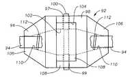
- one aspect of the inventionis to segment the cable and utilize a break-away connector 92 between cable segments 94 .
- Connector 92is comprised of a first fitting 96 that is seated inside a second fitting 98 .
- a shear pin 100is inserted through the fittings 96 , 98 to secure the fittings together.
- the fittingsare attached to the adjacent free ends of cable 94 using any standard means.
- each of fittings 96 , 98has a bore 102 , 104 , respectively, extending from the first end 106 to the second end 108 .
- each fittinghas an aperture 97 , 99 passing through opposing sides of each fitting.
- each bore 102 , 104 at their respective first ends 106is a shoulder 110 .
- Each fittingis inserted over the free end of a cable 98 and a stop 112 is attached to the cable so that stop 112 abuts shoulder 110 and holds the fitting on the end of the cable.
- the bore extending from second end 108 to first end 106may taper and a stop larger than the diameter of the tapered bore can be utilized to secure the fitting on the free cable end.
- each fitting 96 , 98is attached to the end of a cable section 94 such that when the fittings are secured together, the cable sections form a longer length of cable. If the tension in the longer length of cable becomes greater than the shear limit of the shear pin, the shear pin will break away and the longer length of cable will separate. Because the shear pin is easily inserted and removed, the shear limit for the joined cables can easily be adjusted for a particular environment or situation. For example, a shear pin with a shear limit of 5000 lbs may be desirable under certain conditions, whereas a shear pin with a shear limit of 8000 lbs may be desirable in other instances. To the extent the connector is separated under a shear, once the cable is retrieved, the fittings can easily be reattached by replacing the broken shear pin.
- Such a break-away systemis desirable because a cable tensioned beyond its operating limits can snap. For example, in prior art rigid and semi-rigid cables, tensions of 30,000 lbs or more can sometimes be generated. A cable snapping under such a load is likely to result in damage and injury. It is much more desirable to simply retrieve a length of separated cable than to incur such damage and injury.
- the break-away tension of the pods attached to the cableis higher than the break-away tension of the connectors attaching cable segments.
- the cable segmentswill separate before a pod is separated from the cable. This is desirable because it is much easier to locate and retrieve a length of cable, which can be snagged, than it is to locate and retrieve an individual pod which may have separated from the cable.
- FIGS. 12 and 13illustrate a clamping mechanism 120 that permits seismic units to be clamped directly on a length of cable without the need to cut the cable as required in many prior art devices.
- Clamping mechanism 120includes a sleeve 122 with an axial bore 123 therethrough that permits sleeve 122 to be fitted over a cable (not shown).
- Clamping mechanism 120also includes overmolded shoulders 124 , 126 disposed on opposite ends of sleeve 122 .
- An aperture 128passes through each end of sleeve 122 , preferably in both the x and y planes perpendicular to the axis of sleeve 122 .
- sleeve 122includes a ring portion 130 to which a seismic unit may be attached.
- sleeve 122may be tubular without a ring portion 130 .
- Sleeve 122may be integrally formed or may be halves clamped together such as is shown in FIG. 13 , where a sleeve first half 132 and a sleeve second half 134 are clamped around a cable (not shown) and secured to one another with fasteners 136 .
- a pinWhen installed on a cable, a pin is passed through apertures 128 to secure clamping mechanism 120 from sliding on the cable.
- Shoulders 124 , 126are molded over the ends of sleeve 122 and help secure the attachment pins in place.
- the ends of sleeve 122may also be flared to help secure shoulders 124 , 126 in place.
- the sleeve of the inventioncan be clamped or slid onto a length of cable and secured in place without cutting the cable.
- Using pins to secure the mechanism in both the x and y planesprevents rotation of clamping mechanism 120 relative to the cable and prevent slippage axially along the cable.
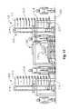
- FIGS. 14-19The back deck of a seismic system deployment and retrieval vessel is illustrated in FIGS. 14-19 .
- a seismic system deployment and retrieval vessel 200having a work deck 202 with a seismic deployment and retrieval system 204 disposed thereon for deploying and retrieving cable 206 .
- a storage rack 208for storing the OBS units attached to cable 206 .
- storage rack 208is scalable to meet the particular pod storage needs and space limitations of a vessel. In FIGS. 14 and 15 , four storage racks 208 have been provided to maximize the pod storage capacity of the particular vessel 200 . As best seen in FIG. 16 , each storage rack 208 is comprised of multiple rows 210 and columns 212 of slots 214 , wherein each slot 214 is disposed for receipt of a pod 216 .
- each slot 214is provided with a communications portal 218 to permit communication between a pod 216 and a master control station (not shown) when pod 216 is seated in slot 214 .
- communications portal 218is linked with pod 216 via the connector 46 shown in pod 10 (see FIG. 1 ).
- the linkmay be a hard wire between communications portal 218 and connector 46 or may be some other method of communication, such as an infrared connector.
- information recorded on the pod 216can be downloaded, the unit batteries can be recharged, quality control checks on the unit can be conducted, the clock can be synchronized, recording can be re-initiated and the unit can be re-activated, all while seated in slot 214 .
- the rows and columns of slotsare replaced by a single stacked column of carousels, preferably semicircular or u-shaped.
- Each carouselincludes rollers to permit the recording units to be moved along the path of the carousel in conveyor type fashion until the units are positioned adjacent a communications portal.
- the shape of the carousel pathis preferably semicircular or u-shaped to permit recording units to be inserted at a first end of the carousel and removed from a second end. Such a configuration would permit pods to be inserted and removed simultaneously from the carousel.
- the first end of the carouselmay be located next to a cleaning station for cleaning pods retrieved from the ocean floor and the second end of the carousel may be located next to a deployment station to permit pods to be reattached to the cable for deployment.
- the storage systemsmay be configured to have the dimensions of a standard 8′ ⁇ 20′ ⁇ 8′ shipping container so that the storage systems and any seismic units stored therein, can be easily transported utilizing standard container ships.
- system 204is shown in which the back deck system is substantially automated.
- a pod deployment system 219running adjacent the racks 208 and extending to the edge of the deck 202 adjacent the water.
- a pick and place system 220is positioned for moving the units 216 between the storage rack 208 and the deployment system 219 . While various automated and semi-automated pick and place systems 220 may be utilized, in the embodiment shown, one or more single axis shuttles 221 are used to move pods 216 between one or more grappling arms 223 that can move pods 216 between racks 208 , shuttles 221 and the deployment system 219 .
- deployment system 219is comprised of a conveyor roller bed 226 running parallel to non-rigid cable 206 and a pod deployment carriage 228 moving in conjunction with conveyor 226 .
- a cable engine 222 and cable spool/container 224are positioned to linearly move non-rigid cable 206 adjacent the deployment system 219 and over the side of the vessel.
- Pods 216are attached to non-rigid cable 206 while cable 206 continues to be paid out into the water, i.e., on-the-fly, by utilizing carriage 228 to accelerate pod 216 to the speed of cable 206 .
- the velocity of cable 206 and pod 216are substantially equivalent, pod 216 is attached to cable 206 , at which point pod 216 is released from carriage 228 and continues to move along conveyor 226 propelled by the cable to which it is attached.
- Conveyor 226has a first end 230 and a second end 232 , wherein the pick and place system 220 is positioned adjacent the first end 230 and one or more cable engines 222 are positioned adjacent the second end 232 , such that pod 216 generally travel along conveyor 226 from the first end 230 to the second end 232 .
- Pod deployment carriage 228likewise runs on a track or frame 234 at least partially along a portion of the length of conveyor 226 . When a pod 216 is ready for deployment, it is pulled from rack 208 utilizing arm 223 and moved on shuttle 221 to a position adjacent the first end 230 of conveyor 226 .
- a grappling arm 223places pod 216 on carriage 228 which is likewise positioned on its track 234 to be adjacent first end 230 of conveyor 226 .
- carriage 228is accelerated down conveyor 226 towards the second end 232 of conveyor 226 .
- pod 216is clamped or otherwise secured to cable 206 .
- pod 216includes a clamp with jaws that can be closed around cable 206 once attachment speed is attained.
- pod 216can be clamped directly onto cable 206 or can be clamped to an attachment sleeve disposed on cable 206 .
- cable engine 222will continue to pull cable 206 , causing pod 216 to move down conveyor 226 until it is deployed over the edge of boat 200 .
- One or more RFID readers 240may be placed along pick and place system 220 and deployment system 219 to track movement of particular pods 216 along deck 202 . Such tracking is particularly desirable with respect to the deployment and retrieval system 204 described above because the self-contained nature of the pods eliminates the need to keep units in a particular order as they are manipulated on deck 202 and inserted into racks 208 .
- the individual pods 10 of the inventionare self contained and each pod's ocean floor location and orientation information is recorded within the pod along with the seismic data recorded at the location, the units need not be kept in sequential or receiver line order as they are retrieved from the ocean, manipulated and stored.
- units that might have been adjacent one another on the shot lineneed not be moved in a particular order through system 204 and need not be stored next to one another in racks 208 , but may be randomly inserted into the storage rack 208 .
- the speed of the cable 206 as it is paid out into the wateris constantly adjusted to compensate for the erratic and unpredictable movement of vessel 220 in the water.
- the speed of the carriage 228 carrying the units 216 for attachment to the cable 206can continually be adjusted to permit pod 216 to be smoothly attached to cable 206 on the fly.
- conveyor 226 , carriage 228 and cable 206are all described in a linear arrangement, it is understood that non-linear arrangements are also encompassed by the invention, so long as such arrangements accelerate a marine seismic unit so as to permit attachment of the unit to a moving cable.
- deployment system 219can be utilized to practice one method of the invention, namely attachment and release of seismic units 216 on the fly without stopping the movement of cable 206 as it is paid out into the water.
- the method which can be used in conjunction with deployment system 219includes the steps of providing a cable moving at a given speed and along a cable path, accelerating a seismic unit along a path adjacent to the cable path until the seismic unit is moving at approximately the speed of the cable and attaching the seismic unit to the cable while both are in motion. In this way, a seismic unit can be attached to a cable and released into the water without the need to stop and start the cable and/or the vessel during deployment, thereby reducing the time necessary to lay out a length of cable along a receiver line.
- a semi-automatic conveyor 250intersects with the cable 206 as it is being pulled from cable spool/container 224 and paid out by the cable engine 222 .
- storage racks 208 and pick and place system 220are arranged on either side of conveyor 250 , in a configuration similar to that shown in FIG. 15 .
- cable 206is spaced apart from conveyor 250 .
- conveyor 250is defined by a first end 252 and a second end 254 .
- a portion 256 of conveyor 250is curved to permit pods 216 to be moved out to cable 206 for attachment of pods 216 to cable 206 at the second end 254 of conveyor 250 .
- a second conveyor 258used to stage pods 216 prior to attachment to cable 206 . Second conveyor 258 moves pods 216 from a position adjacent the pick and place 220 to the first end 254 of conveyor 250 .
- An attachment station 260is defined at the intersection of cable 206 and conveyor 250 .
- a marine seismic unit 216is attached to the cable 206 and the attached unit is subsequently released into the water.
- a cable grabber 262is positioned downstream from the attachment station 260 .
- cable grabber 262is used to securely clamp cable 206 prior to attachment of a unit 216 at attachment station 260 , thereby removing line tension upstream of grabber 260 to permit a unit 216 to be safely attached to cable 206 . This is especially desirable in semi-automated configurations in which personnel manually attach units 216 to cable 206 .
- a cable grabber release system 264may be included at attachment station 260 to minimize the likelihood that personnel are adjacent or in contact with cable 206 at the time cable grabber 262 is released and cable 206 is placed under tension.
- release system 264includes a first button 266 and a second button 268 that must be simultaneously actuated in order to cause a release by cable grabber 262 .
- release system 263functions as a safety device to minimize danger to the operator.
- the back deckis outfitted with two cable deployment systems wherein one system is located on the port side of deck 202 and the other system is located on the starboard side of deck 202 with storage racks 208 , pick and place system 220 and conveyor 250 positioned therebetween.
- Conveyor 250curves out to both sides and each cable deployment system includes a cable spool/container 224 , a cable engine 222 , an attachment station 260 and a cable grabber 262 . Dual systems such as this permit redundancy and ensure that the seismic operation will not be delayed in the event of malfunction of one of the systems.
- One function of the seismic data recording unit of the inventionis the continuous operation of the unit.
- data acquisitionis initiated prior to positioning of the unit on the earth's surface.
- a marine seismic unitis activated and begins acquiring data prior to deployment in the water. Systems that are activated and begin acquiring data prior to deployment are thereby stabilized prior to the time when signal detection is desired. This minimizes the likelihood that an altered state in electronics operation will disrupt signal detection.
- the noveltylies in the “continuous” nature of the unit and such function is applicable whether on land or in a marine environment.
- data recordingis initiated prior to positioning along a receiver line.
- a marine seismic data recording unitis activated while still on the deployment vessel and begins acquiring data prior to deployment in the water. Again, this permits units to stabilize prior to the time signal recording is desired.
- clock stabilizationone component of system stabilization is clock stabilization. Of the various components of the system, it is well known that clocks typically take a long time to stabilize. Thus, in one embodiment of the invention, whether the unit is continuously detecting data or continuously recording data, the clock always remains on.
- the unitcan be utilized in several cycles of deployment and retrieval without interrupting the continuous operation of the unit.
- recordingis initiated.
- the deviceis deployed, retrieved and redeployed, all while recording is continued.
- this continuous recording during multiple cycles of deployment and redeploymentcan be maintained.
- the seismic data unitincludes wrap around memory, it can continuously record even when not in use in seismic detection.
- initiation or start instructionsbecome unnecessary.
- continuous recording utilizing wrap around memoryfunctions as a back-up for data acquired from prior recordings until such time as the prior data is written over.
- the devicecan be utilized to record quality control test data rather than seismic data when conducting quality control tests.
- the data inputchanges from seismic data to quality control data.
- the devicemay resume recording seismic data or other desired data, such as data related to position and timing.
- a marine seismic unitincludes an inertial navigation system to measure the unit's x, y and z position information as the unit is passing through the water column and settles on the ocean floor.
- an inertial navigation systemmeasures movement in each of the x, y and z dimensions as well as angular movement around each x, y and z axis.
- the systemmeasures the six degrees of freedom of the unit as it travels from the vessel to the ocean floor, and utilizes such measurement information to determine location on the ocean floor.
- such x, y and z dimensional informationcan be determined utilizing accelerometers.
- Angular orientationi.e., tilt and direction
- informationcan be determined utilizing a tilt meter and a compass or other orientation devices, such as gyroscopes.
- gyroscopesthree accelerometers and three gyroscopes are utilized to generate the inertial navigation data used to determine the unit's ocean floor position.
- the travel path of the unit through the water columncan be determined. More importantly, the location of the unit at the bottom of the water column, i.e., the location of the unit on the ocean floor, can be determined. Time sampling will occur at appropriate intervals to yield the accuracy needed. Time sampling between various measurement components may vary. For example, data from the compass, used to measure direction, and the tilt meter, used to measure tilt, may be sampled more slowly than data from the accelerometers.
- no other marine seismic unithas utilized one or more accelerometers to determine location in this way.
- the method and systemreplaces the need to determine ocean floor location utilizing other techniques, such as through acoustical location transducers or the like.
- this position determination methodfunctions particularly well with the above described continuous recording method. Because a unit is already recording data as it is discharged into the top of the water column, x, y and z positional information is easily recorded on the unit and becomes part of the unit's complete data record.
- the inventionalso provides for a unique retrieval method for OBS units 300 attached to a cable 302 , as illustrated in FIG. 20 .
- retrieving cable 302 over the trailing end 304 (generally the stern) of a vessel 306 as the vessel moves leading end 308 (often the vessel bow) first down a cable 302 in the direction of the cableminimizes dragging of the cable on the ocean floor 310 as the cable 302 is taken up and prevents undue tension or “pulling” of the cable 302 common in the prior art retrieval technique.
- the water drag on the OBS units and cable in the method of the inventioncauses the cable 302 to parachute or billow out behind vessel 306 , as shown at 312 , utilizing the water column as a shock absorber and minimizing undue tension.
- a flotation release system 314may also be attached to the cable, generally at one or both ends of the deployed cable, to cause at least a portion of the cable to rise to the surface where it can be easily snagged for retrieval utilizing the above described method.
- a flotation release systemis well known in the art and may include a flotation device that is released from near the ocean floor at the desired time of retrieval or a flotation device that floats on the water surface but remains attached to the cable while deployed.
- the non-rigid cable of the inventionis also incorporated in a unique deployment method for the pods, as illustrated in FIG. 21 .
- at least two OBS units 400are tethered together using a non-rigid cable 402 .
- the cable 402 and units 400are deployed into a water column 404 .
- the units 400are of a much greater negative buoyancy than the non-rigid cable 402 , the units will have a tendency to sink through the water column ahead of the cable such that the cable segment adjoining two units parachutes between the two units as shown at 406 .
- the drag of the cable down through the water columnfunctions as a break, slowing the descent of the units and permitting the placement of the units on the ocean floor 408 to be more readily controlled.
- the parachuting effectpermits control of the orientation of units such as those outfitted with the wedge shaped bumper illustrated in FIGS. 6 and 7 .
- the non-rigid cablecause the unit to gently settle on the ocean floor, allowing for consistent coupling of the units to the ocean floor.
- the non-rigid cablepermits slack to form between adjacent units, both during deployment and once settled on the ocean floor.
- the length of the non-rigid cable between two unitswill generally be much greater than the actual spacing between the units once resting on the ocean floor.
- the non-rigid cable of the inventionis not utilized to space units apart from one another.
- a vessel operatorcan utilize the slack that forms in the non-rigid cable to cause correction to a receiver line as it is being laid.
- the vessel at the surfacecan reposition to cause the remainder of the non-rigid cable and attached units to begin settling back on the desired receiver line.
- the slack in the cable resulting from the non-rigid nature of the cablepermits the operator to get back on line and cause the remainder of the individual units to settle in approximately their desired location along the intended line.
- the cablewould not have any adjustment slack and the remainder of the units, while perhaps positioned along the desired receiver line, would not be positioned in the desired location along the receiver line.
- the cable 402 between themis slack, as shown at 410 . This “decouples” individual units from one another and prevents strumming or transmission of undesired noise along the cable.
- clock 20is a crystal clock
- information from the tilt meter 38may be used to correct for gravitational effects on clock timing.
- tilt meter informationhas only been used to correct seismic data.
- crystal clock correctionsto account for temperature effects, no other type of crystal corrections have been made to such clocks.
- one aspect of the inventionutilizes tilt meter information to correct inaccuracies in the clock timing arising from gravitational effects acting on the crystal clock.
- Such clock correctioncan be carried out on-board the pod at or near the time of data recording, or applied to the data once the data has been extracted from the pod.
- information from the tilt meter 38can be used to apply mathematical gimballing to the seismic data.
- seismic datahas been corrected in the prior art to adjust for orientation, such correction has been based on mechanical gimbals installed on board the prior art OBS systems.
- a typical mechanical gimbalcan cause deterioration in the data fidelity due to dampening of the gimbal in its carriage.
- the inventionmay utilize tilt meter information to mathematically adjust the seismic data to account for vertical orientation of the pod.
- Such mathematical gimballingcan be carried out on-board the pod at or near the time of data recording, or may be applied to data once it has been extracted from the pod.
- information from compass 36can be used to further refine the mathematical gimballing to account for rotational orientation of the unit.
- compass datacan be incorporated with the tilt meter data in mathematical gimballing to more fully correct seismic data for effects arising from orientation of a pod.
Landscapes
- Life Sciences & Earth Sciences (AREA)
- Physics & Mathematics (AREA)
- Engineering & Computer Science (AREA)
- Remote Sensing (AREA)
- Acoustics & Sound (AREA)
- Environmental & Geological Engineering (AREA)
- Geology (AREA)
- General Life Sciences & Earth Sciences (AREA)
- General Physics & Mathematics (AREA)
- Geophysics (AREA)
- Oceanography (AREA)
- Geophysics And Detection Of Objects (AREA)
Abstract
Description
Claims (22)
Priority Applications (1)
| Application Number | Priority Date | Filing Date | Title |
|---|---|---|---|
| US12/004,916US7602667B2 (en) | 2003-05-30 | 2007-12-21 | Breakaway deployment cable for underwater seismic recording system |
Applications Claiming Priority (2)
| Application Number | Priority Date | Filing Date | Title |
|---|---|---|---|
| US10/448,547US7310287B2 (en) | 2003-05-30 | 2003-05-30 | Method and apparatus for seismic data acquisition |
| US12/004,916US7602667B2 (en) | 2003-05-30 | 2007-12-21 | Breakaway deployment cable for underwater seismic recording system |
Related Parent Applications (1)
| Application Number | Title | Priority Date | Filing Date |
|---|---|---|---|
| US10/448,547DivisionUS7310287B2 (en) | 2003-05-30 | 2003-05-30 | Method and apparatus for seismic data acquisition |
Publications (2)
| Publication Number | Publication Date |
|---|---|
| US20080137485A1 US20080137485A1 (en) | 2008-06-12 |
| US7602667B2true US7602667B2 (en) | 2009-10-13 |
Family
ID=33516899
Family Applications (19)
| Application Number | Title | Priority Date | Filing Date |
|---|---|---|---|
| US10/448,547Expired - LifetimeUS7310287B2 (en) | 2003-05-30 | 2003-05-30 | Method and apparatus for seismic data acquisition |
| US11/257,836Expired - LifetimeUS7286442B2 (en) | 2003-05-30 | 2005-10-25 | Method and apparatus for seismic data acquisition |
| US11/592,584Expired - LifetimeUS7724607B2 (en) | 2003-05-30 | 2006-11-03 | Method and apparatus for seismic data acquisition |
| US12/004,861AbandonedUS20080106977A1 (en) | 2003-05-30 | 2007-12-21 | Method and apparatus for seismic data acquisition |
| US12/004,918Expired - LifetimeUS7649803B2 (en) | 2003-05-30 | 2007-12-21 | Method for retrieval of seismic data acquisition units |
| US12/004,817Expired - LifetimeUS7804737B2 (en) | 2003-05-30 | 2007-12-21 | Marine vessel working deck for handling of shallow water ocean bottom seismometers |
| US12/004,916Expired - LifetimeUS7602667B2 (en) | 2003-05-30 | 2007-12-21 | Breakaway deployment cable for underwater seismic recording system |
| US12/004,815AbandonedUS20090016157A1 (en) | 2003-05-30 | 2007-12-21 | Non-rigid cable for deployment of ocean bottom seismometers |
| US12/004,529AbandonedUS20080181055A1 (en) | 2003-05-30 | 2007-12-21 | Cable clamping sleeve for ocean bottom seismic recording system |
| US12/781,586Expired - LifetimeUS8050140B2 (en) | 2003-05-30 | 2010-05-17 | Storage system and method for seismic data acquisition units |
| US12/838,859Expired - LifetimeUS7990803B2 (en) | 2003-05-30 | 2010-07-19 | Deployment and retrieval method for shallow water ocean bottom seismometers |
| US13/166,586Expired - LifetimeUS8228761B2 (en) | 2003-05-30 | 2011-06-22 | Ocean bottom seismometer package |
| US13/565,445Expired - LifetimeUS8879362B2 (en) | 2003-05-30 | 2012-08-02 | Ocean bottom seismometer package |
| US14/526,333Expired - LifetimeUS9829594B2 (en) | 2003-05-30 | 2014-10-28 | Ocean bottom seismometer package |
| US15/458,577Expired - LifetimeUS9829589B2 (en) | 2003-05-30 | 2017-03-14 | Ocean bottom seismometer package |
| US15/601,597Expired - LifetimeUS10557958B2 (en) | 2003-05-30 | 2017-05-22 | Ocean bottom seismometer package |
| US15/601,711Expired - LifetimeUS10422908B2 (en) | 2003-05-30 | 2017-05-22 | Ocean bottom seismometer package |
| US15/601,654Expired - LifetimeUS10539696B2 (en) | 2003-05-30 | 2017-05-22 | Ocean bottom seismometer package |
| US16/659,996Expired - LifetimeUS11237285B2 (en) | 2003-05-30 | 2019-10-22 | Ocean bottom seismometer package |
Family Applications Before (6)
| Application Number | Title | Priority Date | Filing Date |
|---|---|---|---|
| US10/448,547Expired - LifetimeUS7310287B2 (en) | 2003-05-30 | 2003-05-30 | Method and apparatus for seismic data acquisition |
| US11/257,836Expired - LifetimeUS7286442B2 (en) | 2003-05-30 | 2005-10-25 | Method and apparatus for seismic data acquisition |
| US11/592,584Expired - LifetimeUS7724607B2 (en) | 2003-05-30 | 2006-11-03 | Method and apparatus for seismic data acquisition |
| US12/004,861AbandonedUS20080106977A1 (en) | 2003-05-30 | 2007-12-21 | Method and apparatus for seismic data acquisition |
| US12/004,918Expired - LifetimeUS7649803B2 (en) | 2003-05-30 | 2007-12-21 | Method for retrieval of seismic data acquisition units |
| US12/004,817Expired - LifetimeUS7804737B2 (en) | 2003-05-30 | 2007-12-21 | Marine vessel working deck for handling of shallow water ocean bottom seismometers |
Family Applications After (12)
| Application Number | Title | Priority Date | Filing Date |
|---|---|---|---|
| US12/004,815AbandonedUS20090016157A1 (en) | 2003-05-30 | 2007-12-21 | Non-rigid cable for deployment of ocean bottom seismometers |
| US12/004,529AbandonedUS20080181055A1 (en) | 2003-05-30 | 2007-12-21 | Cable clamping sleeve for ocean bottom seismic recording system |
| US12/781,586Expired - LifetimeUS8050140B2 (en) | 2003-05-30 | 2010-05-17 | Storage system and method for seismic data acquisition units |
| US12/838,859Expired - LifetimeUS7990803B2 (en) | 2003-05-30 | 2010-07-19 | Deployment and retrieval method for shallow water ocean bottom seismometers |
| US13/166,586Expired - LifetimeUS8228761B2 (en) | 2003-05-30 | 2011-06-22 | Ocean bottom seismometer package |
| US13/565,445Expired - LifetimeUS8879362B2 (en) | 2003-05-30 | 2012-08-02 | Ocean bottom seismometer package |
| US14/526,333Expired - LifetimeUS9829594B2 (en) | 2003-05-30 | 2014-10-28 | Ocean bottom seismometer package |
| US15/458,577Expired - LifetimeUS9829589B2 (en) | 2003-05-30 | 2017-03-14 | Ocean bottom seismometer package |
| US15/601,597Expired - LifetimeUS10557958B2 (en) | 2003-05-30 | 2017-05-22 | Ocean bottom seismometer package |
| US15/601,711Expired - LifetimeUS10422908B2 (en) | 2003-05-30 | 2017-05-22 | Ocean bottom seismometer package |
| US15/601,654Expired - LifetimeUS10539696B2 (en) | 2003-05-30 | 2017-05-22 | Ocean bottom seismometer package |
| US16/659,996Expired - LifetimeUS11237285B2 (en) | 2003-05-30 | 2019-10-22 | Ocean bottom seismometer package |
Country Status (1)
| Country | Link |
|---|---|
| US (19) | US7310287B2 (en) |
Cited By (15)
| Publication number | Priority date | Publication date | Assignee | Title |
|---|---|---|---|---|
| US20110022644A1 (en)* | 2006-09-29 | 2011-01-27 | Ion Geophysical Corporation | For in-field control module for managing wireless seismic data acquisition systems and related methods |
| CN102879807A (en)* | 2011-07-13 | 2013-01-16 | 中国石油天然气集团公司 | Shell of seismograph acquisition station |
| US9429671B2 (en) | 2014-08-07 | 2016-08-30 | Seabed Geosolutions B.V. | Overboard system for deployment and retrieval of autonomous seismic nodes |
| US9459366B2 (en) | 2014-05-15 | 2016-10-04 | Seabed Geosolutions B.V. | Autonomous seismic node handling and storage system |
| US9494700B2 (en) | 2014-06-13 | 2016-11-15 | Seabed Geosolutions B.V. | Node locks for marine deployment of autonomous seismic nodes |
| US9523780B2 (en) | 2014-08-07 | 2016-12-20 | Seabed Geosolutions B.V. | Autonomous seismic nodes for the seabed |
| US9541663B2 (en) | 2014-08-07 | 2017-01-10 | Seabed Geosolutions B.V. | System for automatically attaching and detaching seismic nodes directly to a deployment cable |
| US9720116B2 (en) | 2012-11-02 | 2017-08-01 | Fairfield Industries Incorporated | Land based unit for seismic data acquisition |
| US10024990B2 (en) | 2015-07-07 | 2018-07-17 | Ion Geophysical Corporation | Towed seismic node |
| US10259547B1 (en) | 2017-02-02 | 2019-04-16 | George Kiel | Personal flotation device |
| US10514473B2 (en) | 2015-05-29 | 2019-12-24 | Seabed Geosolutions B.V. | Seabed coupling plate for an ocean bottom seismic node |
| US10641914B2 (en) | 2016-10-17 | 2020-05-05 | Seabed Geosolutions B.V. | Removable fastening mechanism for marine deployment of autonomous seismic nodes |
| US10676162B2 (en) | 2018-10-02 | 2020-06-09 | United States Government As Represented By The Secretary Of The Navy | Autonomous anchor device and methods using deployable blades |
| US10989827B2 (en) | 2017-05-23 | 2021-04-27 | Ion Geophysical Corporation | Seismic node deployment system |
| US11313985B2 (en) | 2018-06-08 | 2022-04-26 | Ion Geophysical Corporation | Sensor node attachment mechanism and cable retrieval system |
Families Citing this family (198)
| Publication number | Priority date | Publication date | Assignee | Title |
|---|---|---|---|---|
| US7310287B2 (en)* | 2003-05-30 | 2007-12-18 | Fairfield Industries Incorporated | Method and apparatus for seismic data acquisition |
| US7561493B2 (en) | 2003-05-30 | 2009-07-14 | Fairfield Industries, Inc. | Method and apparatus for land based seismic data acquisition |
| US8228759B2 (en) | 2003-11-21 | 2012-07-24 | Fairfield Industries Incorporated | System for transmission of seismic data |
| US7124028B2 (en) | 2003-11-21 | 2006-10-17 | Fairfield Industries, Inc. | Method and system for transmission of seismic data |
| US7210556B2 (en)* | 2004-01-15 | 2007-05-01 | Saipem America Inc. | Method and apparatus for installing a sensor array |
| US20080253225A1 (en)* | 2004-01-29 | 2008-10-16 | Welker Kenneth E | Seismic Cable Positioning Using Coupled Inertial System Units |
| CN100347707C (en)* | 2004-03-08 | 2007-11-07 | 中国石油集团东方地球物理勘探有限责任公司 | Data acquisition method for non-realtime transmission earthquake acquisition systems |
| WO2005114106A1 (en)* | 2004-05-12 | 2005-12-01 | Northrop Grumman Corporation | System and method for aligning multiple navignation components |
| US8534959B2 (en) | 2005-01-17 | 2013-09-17 | Fairfield Industries Incorporated | Method and apparatus for deployment of ocean bottom seismometers |
| CN100419457C (en)* | 2005-03-18 | 2008-09-17 | 中国海洋石油总公司 | Marine Seismic Exploration Data Acquisition and Recording System |
| FR2884323B1 (en) | 2005-04-07 | 2007-06-15 | Geophysique Cie Gle | SEISMIC ACQUISITION METHOD AT SEA BOTTOM, GUIDE EQUIPMENT, SEISMIC ACQUISITION ASSEMBLY AND SEISMIC ACQUISITION PLANT FOR IMPLEMENTING SAID METHOD |
| US8127706B2 (en)* | 2005-05-02 | 2012-03-06 | Fairfield Industries Incorporated | Deck configuration for ocean bottom seismometer launch platforms |
| CN100458466C (en)* | 2005-07-05 | 2009-02-04 | 威海双丰物探设备股份有限公司 | MEMS acceleration earthquake sensor |
| KR101182771B1 (en)* | 2005-09-23 | 2012-09-14 | 삼성전자주식회사 | Liquid crystal display panel and method of driving the same and liquid crystal display apparatus using the same |
| US7558157B1 (en)* | 2006-04-26 | 2009-07-07 | Itt Manufacturing Enterprises, Inc. | Sensor synchronization using embedded atomic clocks |
| US7589827B1 (en) | 2006-07-20 | 2009-09-15 | The United States Of America As Represented By The Secretary Of The Navy | System and method for detecting an object in a search space |
| US7773204B1 (en) | 2006-07-20 | 2010-08-10 | United States Of America As Represented By The Secretary Of The Navy | Apparatus and method for spatial encoding of a search space |
| US7660201B2 (en)* | 2006-08-22 | 2010-02-09 | Autoseis, Inc. | Autonomous seismic data acquisition unit |
| US7646670B2 (en)* | 2006-09-28 | 2010-01-12 | CGGVeritas Services (U.S.) Inc. | Autonomous ocean bottom seismic node recording device |
| KR100749806B1 (en)* | 2006-09-29 | 2007-08-17 | 한국전자통신연구원 | Wireless network-based robot tip and work robot control method |
| US8060314B2 (en)* | 2007-04-19 | 2011-11-15 | Westerngeco L. L. C. | Updating information regarding sections of a streamer that are in a body of water |
| US8021080B2 (en)* | 2007-04-26 | 2011-09-20 | Westerngeco L.L.C. | Containerized geophysical equipment handling and storage systems, and methods of use |
| US8571711B2 (en) | 2007-07-10 | 2013-10-29 | Raytheon Company | Modular robotic crawler |
| US7632043B2 (en)* | 2007-08-23 | 2009-12-15 | Fairfield Industries Incorporated | Seismic sensor transfer device |
| US8605543B2 (en)* | 2007-09-21 | 2013-12-10 | Fairfield Industries Incorporated | Method and apparatus for correcting the timing function in a nodal seismic data acquisition unit |
| CA2996790C (en) | 2007-09-21 | 2022-03-08 | Fairfield Industries, Inc. | Method and apparatus for correcting the timing function in a nodal seismic data acquisition unit |
| ITUD20070196A1 (en) | 2007-10-24 | 2009-04-25 | Baccini S P A | AUTOMATIC WAREHOUSE AND PROCEDURE FOR STORAGE OF ELECTRONIC CIRCUIT PLATES |
| US9207337B2 (en) | 2007-12-12 | 2015-12-08 | Westerngeco L.L.C. | Systems and methods for seismic data acquisition employing clock source selection in seismic nodes |
| CN101592736A (en)* | 2008-05-30 | 2009-12-02 | 陈�峰 | High-precision intelligent quadrant earthquake tester |
| US8061470B2 (en)* | 2008-06-25 | 2011-11-22 | Schlumberger Technology Corporation | Method and apparatus for deploying a plurality of seismic devices into a borehole and method thereof |
| US7883292B2 (en)* | 2008-06-30 | 2011-02-08 | Fairfield Industries Incorporated | Node storage, deployment and retrieval system |
| NO332562B1 (en)* | 2008-07-04 | 2012-10-29 | Multifield Geophysics As | Marine seismic and electromagnetic streamer cable |
| US8087848B2 (en)* | 2008-08-27 | 2012-01-03 | Fairfield Industries Incorporated | Powered sheave for node deployment and retrieval |
| US8226328B2 (en) | 2008-09-03 | 2012-07-24 | Fairfield Industries Incorporated | Seismic cable with adjustable buoyancy |
| US7933165B2 (en)* | 2008-09-03 | 2011-04-26 | Fairfield Industries Incorporated | Connector for seismic cable |
| US8942059B2 (en)* | 2008-09-19 | 2015-01-27 | Optoplan As | Container system for seismic cable and stations |
| CN101726752B (en)* | 2008-10-23 | 2012-06-20 | 鸿富锦精密工业(深圳)有限公司 | Earthquake monitoring system |
| CN103064109B (en)* | 2008-11-04 | 2017-07-18 | 费尔菲尔德工业公司 | Method and apparatus for correcting the clocking capability in nodal seismic data acquisition unit |
| US8310899B2 (en) | 2008-12-23 | 2012-11-13 | Fairfield Industries Incorporated | Multiple receiver line deployment and recovery |
| US10042068B2 (en) | 2008-12-23 | 2018-08-07 | Fairfield Industries Incorporated | Conveyance system and method for underwater seismic exploration |
| US8098542B2 (en)* | 2009-01-05 | 2012-01-17 | Pgs Geophysical As | Combined electromagnetic and seismic acquisition system and method |
| FR2940838B1 (en)* | 2009-01-05 | 2012-12-28 | Michel Manin | IMPROVED METHOD AND APPARATUS FOR SEISMIC MARINE PROSPECTING |
| US9304216B2 (en)* | 2009-02-05 | 2016-04-05 | Westerngeco L.L.C. | Seismic acquisition system and technique |
| US9535182B2 (en)* | 2009-03-09 | 2017-01-03 | Ion Geophysical Corporation | Marine seismic surveying with towed components below water surface |
| US8593905B2 (en) | 2009-03-09 | 2013-11-26 | Ion Geophysical Corporation | Marine seismic surveying in icy or obstructed waters |
| US9354343B2 (en) | 2009-03-09 | 2016-05-31 | Ion Geophysical Corporation | Declination compensation for seismic survey |
| US9389328B2 (en) | 2009-03-09 | 2016-07-12 | Ion Geophysical Corporation | Marine seismic surveying with towed components below water's surface |
| US8085620B2 (en)* | 2009-03-27 | 2011-12-27 | Westerngeco L.L.C. | Determining a position of a survey receiver in a body of water |
| IT1394049B1 (en)* | 2009-04-16 | 2012-05-25 | Milano Politecnico | SYSTEM AND METHOD OF DETECTION FOR THE MEASUREMENT OF THE PHENOMENA OF ALTIMETRIC VARIATION OF THE MARINE FONDALS |
| US8255164B2 (en)* | 2009-04-22 | 2012-08-28 | Schlumberger Technology Corporation | Methods and systems for borehole seismic |
| US20100278011A1 (en)* | 2009-05-01 | 2010-11-04 | Pgs Geophysical As | System and method for towed marine geophysical equipment |
| WO2010144813A1 (en)* | 2009-06-11 | 2010-12-16 | Raytheon Sarcos, Llc | Method and system for deploying a surveillance network |
| GB2476523B (en)* | 2009-08-06 | 2011-12-28 | Champion Partnership | Electronically readable and/or writable identification sign |
| US9170344B2 (en)* | 2009-08-31 | 2015-10-27 | Autoseis, Inc. | System and method for deployment of seismic data recorders |
| US20110176383A1 (en)* | 2010-01-19 | 2011-07-21 | Fairfield Industries Incorporated | Method and apparatus for accurate placement of ocean bottom seismic instrumentation |
| US20110174207A1 (en)* | 2010-01-21 | 2011-07-21 | Pgs Geophysical As | System and method for using copper coating to prevent marine growth on towed geophysical equipment |
| US20110205840A1 (en)* | 2010-02-19 | 2011-08-25 | Hayes Robert W | Seismic equipment handling |
| US8579545B2 (en) | 2010-03-02 | 2013-11-12 | Fairfield Industries Incorporated | Apparatus and methods for an ocean bottom seismic sensor deployment vehicle |
| US20110228635A1 (en)* | 2010-03-22 | 2011-09-22 | Pgs Geophysical As | Self-positioning nodal geophysical recorder |
| US9217804B2 (en)* | 2010-03-26 | 2015-12-22 | Shell Oil Company | Seismic clock timing correction using ocean acoustic waves |
| US8514664B2 (en) | 2010-04-16 | 2013-08-20 | Pgs Geophysical As | System and method for gathering marine geophysical data |
| NO331416B1 (en) | 2010-05-07 | 2011-12-27 | Magseis As | Seismic subsea cable recording apparatus, and methods for laying and retrieving the seismic subsea cable recording apparatus |
| US20110310698A1 (en) | 2010-06-21 | 2011-12-22 | Sercel, Inc. | Dual Axis Geophones For Pressure/Velocity Sensing Streamers Forming a Triple Component Streamer |
| US9395460B2 (en) | 2010-07-19 | 2016-07-19 | Conocophillips Company | Continuous composite relatively adjusted pulse |
| CN101963675B (en)* | 2010-08-26 | 2012-05-30 | 成都理工大学 | Multipath dynamically-reconfigurable signal processing system |
| CN101984365B (en)* | 2010-10-22 | 2012-08-29 | 中国石油化工股份有限公司 | Micro-electromechanical digital geophone communication system and method |
| CN101975967B (en)* | 2010-10-22 | 2012-08-29 | 中国海洋石油总公司 | Towed cable simulation system for geophysical exploration |
| CN101975966B (en)* | 2010-10-22 | 2012-08-15 | 中国海洋石油总公司 | Towrope simulator board for geophysical exploration |
| TW201224500A (en)* | 2010-10-24 | 2012-06-16 | Takamune Cho | Method and system for detecting ground displacement |
| WO2012071226A1 (en)* | 2010-11-23 | 2012-05-31 | Conocophillips Company | Electrical methods seismic interface box |
| US9116253B2 (en) | 2011-01-11 | 2015-08-25 | Pgs Geophysical As | System and method for using biocide coating to prevent marine growth on geophysical equipment |
| GB201102576D0 (en)* | 2011-02-15 | 2011-03-30 | Go Science Ltd | Seismic sensor node with serrated annular skirt |
| GB201102577D0 (en)* | 2011-02-15 | 2011-03-30 | Go Science Ltd | Annular seismic sensor node |
| US9016227B2 (en)* | 2011-03-31 | 2015-04-28 | Cggveritas Services Sa | Anti-barnacle net and method |
| CN102288989B (en)* | 2011-05-17 | 2012-08-29 | 中国科学院地质与地球物理研究所 | Combined broadband ocean bottom seismograph with single compartment ball |
| CN103149602B (en)* | 2011-06-15 | 2016-01-27 | 中国海洋石油总公司 | A kind of proving installation of geophysical survey digital packets |
| US20130028047A1 (en)* | 2011-07-28 | 2013-01-31 | Yury Georgievich Erofeev | Bottom module for seismic survey |
| EP2770343A4 (en)* | 2011-10-17 | 2016-06-01 | Inst Geology & Geophysics Cas | DIGITAL ALL-IN-ONE DIGITAL SISMOMETER WIRELESS, WIRELESS AND WITHOUT CABLE |
| RU2483331C1 (en)* | 2011-12-09 | 2013-05-27 | Открытое акционерное общество "Мурманское морское пароходство" | System for towing overboard seismic equipment |
| US9013953B2 (en) | 2012-01-20 | 2015-04-21 | Cggveritas Services Sa | Buoy based marine seismic survey system and method |
| US20150043310A1 (en)* | 2012-03-08 | 2015-02-12 | Shell Oil Company | Sensor station, system and method for sensing seismic parameters |
| CN104919339B (en) | 2012-03-08 | 2018-01-12 | 国际壳牌研究有限公司 | Integrated earthquake monitoring system and method |
| US9664805B2 (en) | 2012-03-08 | 2017-05-30 | Shell Oil Company | Seismic cable handling system and method |
| US9256002B2 (en)* | 2012-04-09 | 2016-02-09 | Fairfield Industries Incorporated | Coupler/ coupling ring assembly, methods, and applications |
| US8966718B2 (en) | 2012-04-09 | 2015-03-03 | Fairfield Industries Incorporated | Coupling ring, methods and applications |
| US9003612B2 (en) | 2012-04-09 | 2015-04-14 | Fairfield Industries Incorporated | Coupler, methods, and applications |
| FR2990028B1 (en)* | 2012-04-25 | 2014-05-16 | Kietta | ACQUISITION OF SEISMIC DATA |
| EP2657725B1 (en)* | 2012-04-27 | 2015-01-14 | Sercel | Method and system for managing a multi-vessel seismic system |
| RU2496126C1 (en)* | 2012-05-03 | 2013-10-20 | Федеральное государственное бюджетное учреждение науки Институт океанологии им. П.П. Ширшова РАН | Offshore hydrophysical system |
| AU2013211510A1 (en)* | 2012-08-09 | 2014-02-27 | Cgg Services Sa | Adaptive sweep method and device for seismic exploration |
| NO336544B1 (en) | 2012-08-16 | 2015-09-21 | Magseis As | Autonomous seabed seismic node comprising a reference oscillator |
| CN102841372B (en)* | 2012-08-30 | 2015-02-25 | 合肥国为电子有限公司 | Cascade-collecting-station high-efficiency production line data transmission system used for seismic exploration and data transmission method |
| USD698270S1 (en)* | 2012-09-14 | 2014-01-28 | Cggveritas Services Sa | Seismic node |
| US9383471B2 (en)* | 2012-09-14 | 2016-07-05 | Cgg Services Sa | Method and underwater node for seismic survey |
| US20140081659A1 (en) | 2012-09-17 | 2014-03-20 | Depuy Orthopaedics, Inc. | Systems and methods for surgical and interventional planning, support, post-operative follow-up, and functional recovery tracking |
| WO2014062826A1 (en) | 2012-10-16 | 2014-04-24 | Conocophillips Company | Flared pseudo-random spiral marine acquisition |
| US9031698B2 (en) | 2012-10-31 | 2015-05-12 | Sarcos Lc | Serpentine robotic crawler |
| US9465078B2 (en) | 2012-11-02 | 2016-10-11 | Fairfield Industries, Inc. | Battery capacity and durability prediction method |
| NO335830B1 (en) | 2012-11-27 | 2015-03-02 | Magseis As | Connecting sensor caps to and from a running seismic cable on a vessel |
| MY175453A (en)* | 2012-12-13 | 2020-06-29 | Fairfield Ind Inc | Delivery and recovery apparatus, method, and applications |
| US20140185408A1 (en)* | 2012-12-28 | 2014-07-03 | Vladimir Eduardovich Kyasper | Bottom seismic system |
| US9360575B2 (en)* | 2013-01-11 | 2016-06-07 | Fairfield Industries Incorporated | Simultaneous shooting nodal acquisition seismic survey methods |
| US9448311B2 (en) | 2013-01-31 | 2016-09-20 | Seabed Geosolutions B.V. | Underwater node for seismic surveys and method |
| CH707573A1 (en)* | 2013-02-07 | 2014-08-15 | Thomas Frizlen | Method and system for determining the displacement of an anchor. |
| US9845137B2 (en) | 2013-03-20 | 2017-12-19 | Seabed Geosolutions B.V. | Methods and underwater bases for using autonomous underwater vehicle for marine seismic surveys |
| CN103217717B (en)* | 2013-03-28 | 2015-09-30 | 中国海洋石油总公司 | A kind of marine seismic exploration towline equipment |
| US9465127B2 (en) | 2013-05-07 | 2016-10-11 | Pgs Geophysical As | Disposable antifouling covers for geophysical survey equipment |
| NO335875B1 (en)* | 2013-05-14 | 2015-03-16 | Magseis As | Methods and Devices for Handling Sensor Caps in Laying and Obtaining a Seismic Cable |
| CN103310114A (en)* | 2013-06-27 | 2013-09-18 | 浙江大学 | Space synchronization method for ocean monitoring data |
| US9441965B1 (en)* | 2013-06-28 | 2016-09-13 | The United States Of America As Represented By The Secretary Of The Navy | Oceangraphic assembly for collecting data along multiple water columns |
| NO335818B1 (en) | 2013-08-06 | 2015-02-23 | Magseis As | Storage cabinet with docking stations for autonomous seismic sensor nodes |
| US9409292B2 (en) | 2013-09-13 | 2016-08-09 | Sarcos Lc | Serpentine robotic crawler for performing dexterous operations |
| US10054701B2 (en)* | 2013-09-20 | 2018-08-21 | Westerngeco L.L.C. | Seismic data recorder charging and data offload |
| US20150276955A1 (en)* | 2013-11-06 | 2015-10-01 | Robert H. Brune | Method and System for Extending Spatial Wavenumber Spectrum Of Seismic Wavefields On Land Or Water Bottom Using Rotational Motion |
| CN105960599A (en)* | 2013-12-10 | 2016-09-21 | 离子地球物理学公司 | Obstruction overlay cable |
| NO336053B1 (en)* | 2013-12-11 | 2015-04-27 | Magseis As | Apparatus and method for handling a seabed cable |
| US9709689B2 (en)* | 2014-02-07 | 2017-07-18 | Pgs Geophysical As | Geophysical cable preparation for antifouling paint |
| WO2015125015A2 (en) | 2014-02-19 | 2015-08-27 | Cgg Services Sa | Systems and methods for wireless data acquisition in seismic monitoring systems |
| US9566711B2 (en) | 2014-03-04 | 2017-02-14 | Sarcos Lc | Coordinated robotic control |
| NO337396B1 (en) | 2014-03-07 | 2016-04-04 | Seafloor Geophysical Solutions As | System and method for connecting seismic seabed nodes to a towed cable |
| US10473806B2 (en)* | 2014-05-13 | 2019-11-12 | Ion Geophysical Corporation | Ocean bottom system |
| AU2015289607B2 (en)* | 2014-07-17 | 2020-09-03 | Conocophillips Company | Marine seismic surveying including direct far field measurements |
| US9595833B2 (en) | 2014-07-24 | 2017-03-14 | Seabed Geosolutions B.V. | Inductive power for seismic sensor node |
| US9768626B2 (en) | 2014-08-19 | 2017-09-19 | Seabed Geosolutions B.V. | Simultaneous charging of a plurality of autonomous seismic nodes |
| WO2016032999A1 (en) | 2014-08-25 | 2016-03-03 | Westerngeco Llc | Storing sensor devices |
| US20160094298A1 (en)* | 2014-09-25 | 2016-03-31 | Seabed Geosolutions B.V. | Wireless data transfer for an autonomous seismic node |
| US9873496B2 (en) | 2014-10-29 | 2018-01-23 | Seabed Geosolutions B.V. | Deployment and retrieval of seismic autonomous underwater vehicles |
| EP3213121B1 (en) | 2014-10-29 | 2021-05-05 | Seabed Geosolutions B.V. | Touch down monitoring of an ocean bottom seismic node |
| NO20150200A1 (en)* | 2015-02-11 | 2016-05-18 | Inapril As | A device for attaching a seismic node to a cable, a seismic node, as well as a method for deployment and retrieval of seismic nodes attached to a cable |
| WO2016135614A1 (en) | 2015-02-24 | 2016-09-01 | Seabed Geosolutions Bv | Single vessel range navigation and positioning of an ocean bottom seismic node |
| CN104678430B (en)* | 2015-03-11 | 2017-05-31 | 中国地震局地震研究所 | Based on many of the underground seismometer horizontalization device regulated and controled on well |
| CA2923710A1 (en)* | 2015-03-13 | 2016-09-13 | Kraken Sonar Systems Inc. | Underwater navigation system |
| US10901102B2 (en)* | 2015-04-09 | 2021-01-26 | Teledyne Instruments, Inc. | Digital seismic source signature near-field hydrophone |
| CN107076584B (en) | 2015-05-08 | 2020-11-24 | 辉固科技有限公司 | Optical sensor device, and cable |
| US10345462B2 (en) | 2015-05-29 | 2019-07-09 | Seabed Geosolutions B.V. | Flat contact quick connect connection for an autonomous seismic node |
| US10071303B2 (en) | 2015-08-26 | 2018-09-11 | Malibu Innovations, LLC | Mobilized cooler device with fork hanger assembly |
| US10322783B2 (en) | 2015-10-16 | 2019-06-18 | Seabed Geosolutions B.V. | Seismic autonomous underwater vehicle |
| US10274627B2 (en) | 2015-10-30 | 2019-04-30 | Ion Geophysical Corporation | Ocean bottom seismic systems |
| CN108463743B (en)* | 2015-11-17 | 2020-03-13 | 费尔菲尔德工业公司 | Back deck automation device |
| US10818382B1 (en) | 2015-11-20 | 2020-10-27 | Massachusetts Mutual Life Insurance Company | Systems, methods, and apparatus for acquiring data |
| US10018742B2 (en) | 2016-03-31 | 2018-07-10 | Fairfield Industries, Inc. | Skid structure for underwater seismic exploration |
| US10048397B2 (en) | 2016-03-31 | 2018-08-14 | Fairfield Industries, Inc. | Conveyance system and method for underwater seismic exploration |
| US10114137B2 (en) | 2016-03-31 | 2018-10-30 | Fairfield Industries, Inc. | Underwater seismic exploration with a helical conveyor and skid structure |
| US9841522B2 (en) | 2016-03-31 | 2017-12-12 | Fairfield Industries, Inc. | Loading a helical conveyor for underwater seismic exploration |
| US10151848B2 (en) | 2016-03-31 | 2018-12-11 | Fairfield Industries, Inc. | Helical conveyor for underwater seismic exploration |
| US10807659B2 (en) | 2016-05-27 | 2020-10-20 | Joseph L. Pikulski | Motorized platforms |
| RU2657128C2 (en)* | 2016-06-30 | 2018-06-08 | Федеральное государственное бюджетное учреждение "Всероссийский научно-исследовательский институт геологии и минеральных ресурсов Мирового океана имени академика И.С. Грамберга" | Method of a complex system for the search and exploration of hydrocarbon deposits by seismic and electromagnetic methods in the shelf area |
| US11243316B2 (en) | 2016-07-18 | 2022-02-08 | Shell Oil Company | Seismic sensor station |
| AU2017299469B2 (en) | 2016-07-18 | 2020-07-09 | Shell Internationale Research Maatschappij B.V. | Seismic sensor station |
| FR3054890B1 (en) | 2016-08-02 | 2019-07-05 | Kietta | CHECKING THE HORIZONTAL POSITION OF A SEISMIC CABLE |
| CN106527976B (en)* | 2016-10-13 | 2019-05-24 | 中国船舶工业系统工程研究院 | A kind of marine geophysical prospecting data storage processing system based on SATA interface |
| US10352705B2 (en)* | 2016-10-31 | 2019-07-16 | Deepblu Inc. | Positioning method for obtaining at least one underwater position of a positioning system |
| RU168834U1 (en)* | 2016-11-09 | 2017-02-21 | АО "Акустический институт имени академика Н.Н. Андреева" | Universal bottom station |
| CN106772558A (en)* | 2016-12-28 | 2017-05-31 | 钦州市中航科技咨询有限公司 | A kind of submarine earthquake monitoring system |
| EP3577497B1 (en) | 2017-02-06 | 2025-09-24 | Seabed Geosolutions B.V. | Ocean bottom seismic autonomous underwater vehicle |
| US10310110B2 (en) | 2017-02-21 | 2019-06-04 | Geospace Technologies Corporation | Systems and methods for seismic data acquisition |
| CN110476087B (en)* | 2017-03-08 | 2024-07-30 | 英洛瓦有限公司 | Seismic data acquisition unit and related methods |
| WO2018227054A1 (en)* | 2017-06-09 | 2018-12-13 | Fairfield Industries Incorporated | Seismic data acquisition unit |
| FR3071476B1 (en)* | 2017-09-25 | 2019-10-11 | Cgg Services Sas | SYSTEM FOR RECOVERING AND DEPLOYING SEISMIC SOURCES AND SHIP COMPRISING SUCH A SYSTEM AND ASSOCIATED METHODS |
| US10625824B2 (en)* | 2018-01-13 | 2020-04-21 | Thomas Frizlen | Method and system for determining displacement of an anchor |
| WO2019195286A1 (en)* | 2018-04-02 | 2019-10-10 | Magseis Ff Llc | Systems and methods to locate seismic data acquisition units |
| US11255998B2 (en) | 2018-05-17 | 2022-02-22 | Seabed Geosolutions B.V. | Cathedral body structure for an ocean bottom seismic node |
| US11249214B2 (en)* | 2018-05-30 | 2022-02-15 | Saudi Arabian Oil Company | Noise suppression of seafloor geophone seismic data |
| NO344845B1 (en)* | 2018-07-10 | 2020-05-25 | Magseis Asa | A seismic node for an ocean bottom seismic survey comprising a seismic sensor capsule and a seafloor casing, a method for performing an ocean bottom seismic survey and the use of the seismic node for achieving the method |
| US11524756B2 (en) | 2018-08-27 | 2022-12-13 | Pgs Geophysical As | Ocean bottom node deployment |
| US11204365B2 (en) | 2018-09-13 | 2021-12-21 | Ion Geophysical Corporation | Multi-axis, single mass accelerometer |
| US11609350B2 (en)* | 2018-10-12 | 2023-03-21 | Magseis Ff Llc | Modular seismic unit storage system with gantry robot and charging magazine |
| CN109460061B (en)* | 2018-12-12 | 2020-08-25 | 自然资源部第二海洋研究所 | Parallel operation method for autonomous underwater robot and geological sampling equipment |
| CN110007337B (en)* | 2019-04-24 | 2020-04-10 | 自然资源部第一海洋研究所 | Synchronous self-contained hydrophone underwater sound signal acquisition system and working method |
| US11668846B2 (en) | 2019-08-20 | 2023-06-06 | Pgs Geophysical As | Seismic sensor alignment preserver |
| CN111175811B (en)* | 2019-10-29 | 2022-03-15 | 自然资源部第二海洋研究所 | Ocean bottom seismograph equipment capable of improving signal-to-noise ratio |
| CN111175828B (en)* | 2019-10-29 | 2022-03-15 | 自然资源部第二海洋研究所 | Ballast anchor device for submarine seismograph |
| CN111257940B (en)* | 2020-02-14 | 2020-09-04 | 中国科学院地质与地球物理研究所 | Combined type submarine seismograph attitude automatic correction device and method |
| CN111257941B (en)* | 2020-02-18 | 2020-09-04 | 中国科学院地质与地球物理研究所 | A combined submarine seismograph azimuth automatic identification device and method |
| CN111561961A (en)* | 2020-03-17 | 2020-08-21 | 中国船舶重工集团公司第七一五研究所 | Marine information acquisition system and method for synchronizing additional time information |
| CN111290014B (en)* | 2020-03-26 | 2022-11-01 | 国家深海基地管理中心 | Seismic cable detection device, process detection method and anti-interference detection method |
| US11474267B2 (en) | 2020-06-11 | 2022-10-18 | China Petroleum & Chemical Corporation | Computer-implemented method and system employing compress-sensing model for migrating seismic-over-land cross-spreads |
| US12429373B2 (en)* | 2020-08-12 | 2025-09-30 | Nec Corporation | Aquatic organism observation device, aquatic organism observation system, aquatic organism observation method, and recording medium |
| WO2022081314A1 (en) | 2020-10-15 | 2022-04-21 | Ion Geophysical Corporation | Neutrally buoyant particle velocity sensor |
| CN112099076B (en)* | 2020-11-23 | 2021-03-02 | 上海彩虹鱼海洋科技股份有限公司 | Spiral penetration type submarine seismograph coupling frame |
| US12311550B2 (en) | 2020-12-31 | 2025-05-27 | Sarcos Corp. | Smart control system for a robotic device |
| WO2022231567A1 (en) | 2021-04-26 | 2022-11-03 | Maurice Nessim | Systems and methods for object location detection such as detecting airplane crash location |
| RU2770130C1 (en)* | 2021-04-27 | 2022-04-14 | Владимир Васильевич Чернявец | Drifting buoy hydroacoustic station for determining the precursors of strong earthquakes and tsunamis in ice-covered water areas |
| RU2766830C1 (en)* | 2021-06-11 | 2022-03-16 | Федеральное государственное бюджетное учреждение науки Тихоокеанский океанологический институт им. В.И. Ильичева Дальневосточного отделения Российской академии наук (ТОИ ДВО РАН) | Portable device for autonomous recorders of hydrophysical parameters |
| CN113466930B (en)* | 2021-07-20 | 2024-06-07 | 北京市水电物探研究所 | Micro-motion exploration method and device and electronic equipment |
| GB202113202D0 (en) | 2021-09-15 | 2021-10-27 | Magseis Fairfield ASA | Collaboration platform for seismic data products and seismic data services |
| CN113978632B (en)* | 2021-10-28 | 2023-05-26 | 浙江海洋大学 | Ocean self-adaptive underwater bottom-sitting type observation platform and use method thereof |
| US20230138628A1 (en)* | 2021-10-28 | 2023-05-04 | SKIVER and CROW LLC | Geographical marker system |
| CN114644087B (en)* | 2021-12-31 | 2023-03-28 | 自然资源部第二海洋研究所 | Short base line bearing structure suitable for ice district |
| CN114609673B (en)* | 2022-03-10 | 2022-12-09 | 中国科学院地质与地球物理研究所 | Combined type submarine earthquake acquisition node with secondary positioning function |
| NO20220390A1 (en) | 2022-03-30 | 2023-10-02 | Magseis Fairfield ASA | Method of and system for transmitting seismic data from a subsea seismic sensor |
| CN114466552B (en)* | 2022-04-12 | 2022-07-05 | 自然资源部第一海洋研究所 | Submersible buoy device and control method thereof |
| US12403987B2 (en)* | 2022-05-25 | 2025-09-02 | United States Of America As Represented By The Secretary Of The Navy | Split release benthic lander |
| EP4391259A1 (en)* | 2022-12-19 | 2024-06-26 | Nexans | Work platform for performing a cable operation on a vessel deck |
| NO20230049A1 (en) | 2023-01-20 | 2024-07-22 | Magseis Fairfield As | Data recorder system for use in a Seismic Survey and a Method of Carrying out a Seismic Survey |
| WO2024161139A1 (en) | 2023-02-01 | 2024-08-08 | Pxgeo Uk Limited | System and method for using autonomous underwater vehicles for ocean bottom seismic nodes |
| WO2024165848A1 (en) | 2023-02-10 | 2024-08-15 | Pxgeo Uk Limited | Autonomous seismic node for the seabed |
| WO2025168935A1 (en) | 2024-02-06 | 2025-08-14 | Pxgeo Uk Limited | System and method for using autonomous underwater vehicles for ocean bottom seismic nodes |
Citations (87)
| Publication number | Priority date | Publication date | Assignee | Title |
|---|---|---|---|---|
| US3297982A (en) | 1963-05-07 | 1967-01-10 | Atomic Energy Authority Uk | Horizontal seismometer |
| US3499664A (en)* | 1968-07-29 | 1970-03-10 | Bruns Tool Co | Releasing collar |
| US3786410A (en)* | 1971-12-27 | 1974-01-15 | Mark Products | Seismic cable assembly |
| US4144520A (en) | 1977-02-03 | 1979-03-13 | Geo Space Corporation | Geophone having electromagnetic damping means |
| US4281403A (en) | 1979-09-12 | 1981-07-28 | Litton Resources Systems, Inc. | Seismic data recording method and apparatus |
| US4300220A (en) | 1980-05-16 | 1981-11-10 | Phillips Petroleum Co. | Three component detector and housing for same |
| US4380059A (en) | 1980-08-20 | 1983-04-12 | Mobil Oil Corporation | F-K Filtering of multiple reflections from a seismic section |
| US4422164A (en) | 1980-06-27 | 1983-12-20 | Mobil Oil Corporation | On-bottom seismometer electronic system |
| US4458339A (en) | 1980-10-06 | 1984-07-03 | Texas Instruments Incorporated | Seismic prospecting using a continuous shooting and continuous recording system |
| US4462094A (en) | 1980-06-19 | 1984-07-24 | Mobil Oil Corporation | Method and apparatus for determining angle of inclination of seismometer and leveling seismic motion detectors |
| US4486865A (en) | 1980-09-02 | 1984-12-04 | Mobil Oil Corporation | Pressure and velocity detectors for seismic exploration |
| US4525819A (en) | 1982-12-06 | 1985-06-25 | Oyo Corporation, U.S.A. | Horizontal geophone transducer assembly |
| US4613821A (en) | 1983-01-10 | 1986-09-23 | Conoco Inc. | Method and apparatus for obtaining high accuracy simultaneous calibration of signal measuring systems |
| US4666338A (en) | 1984-01-04 | 1987-05-19 | Mobil Oil Corporation | Ocean bottom seismometer release mechanism |
| US4692906A (en) | 1984-01-04 | 1987-09-08 | Mobil Oil Corporation | Ocean bottom seisometer |
| US4813029A (en) | 1981-08-05 | 1989-03-14 | Union Oil Company Of California | Geophone apparatus and a seismic exploration method |
| US4839872A (en) | 1987-05-19 | 1989-06-13 | Thomson-Csf | Geophone with a sensitive element made of piezoelectric polymer |
| US4849947A (en) | 1986-05-27 | 1989-07-18 | Wasagchemie Sythen Gmbh | Acoustic ground vibration detector |
| US4884248A (en) | 1988-01-25 | 1989-11-28 | Mobil Oil Corporation | Method of restoring seismic data |
| US4979150A (en) | 1989-08-25 | 1990-12-18 | Halliburton Geophysical Services, Inc. | System for attenuation of water-column reverberations |
| US5003517A (en) | 1982-11-29 | 1991-03-26 | American Fuel Cell And Coated Fabrics Company | Magnetohydrodynamic fluid apparatus and method |
| US5010531A (en) | 1989-10-02 | 1991-04-23 | Western Atlas International, Inc. | Three-dimensional geophone |
| US5067112A (en) | 1991-01-04 | 1991-11-19 | Mobil Oil Corporation | Method for removing coherent noise from seismic data through f-x filtering |
| US5119345A (en) | 1991-05-03 | 1992-06-02 | Shaw Industries Ltd. | Geophone |
| US5138538A (en) | 1991-03-25 | 1992-08-11 | Sperling Michael Z | Self-extinguishing flashlight |
| US5163028A (en) | 1991-09-27 | 1992-11-10 | Halliburton Geophysical Services, Inc. | Method for correcting impulse response differences of hydrophones and geophones as well as geophone coupling to the water-bottom in dual-sensor, bottom-cable seismic operations |
| US5189642A (en) | 1991-09-10 | 1993-02-23 | Chevron Research And Technology Company | Seafloor seismic recorder |
| US5191526A (en) | 1988-07-18 | 1993-03-02 | Mobil Oil Corporation | Method for removing coherent noise from seismic data |
| US5214614A (en) | 1989-10-18 | 1993-05-25 | Wasagchemie Sythen Gesellschaft Mit Beschrankter Haftung | Seismic directional sensor for solid-borne sound |
| US5231252A (en) | 1992-06-19 | 1993-07-27 | Sansone Stanley A | Sensor platform for use in seismic reflection surveys |
| US5253223A (en) | 1989-10-26 | 1993-10-12 | Den Norske Stats Oljeselskap A.S. | Seismic device |
| US5274605A (en) | 1992-06-26 | 1993-12-28 | Chevron Research And Technology Company | Depth migration method using Gaussian beams |
| GB2275337A (en) | 1993-02-17 | 1994-08-24 | Csm Associates Limited | Seismic detector |
| US5365492A (en) | 1993-08-04 | 1994-11-15 | Western Atlas International, Inc. | Method for reverberation suppression |
| US5432895A (en) | 1992-10-01 | 1995-07-11 | University Corporation For Atmospheric Research | Virtual reality imaging system |
| US5469408A (en) | 1994-07-20 | 1995-11-21 | Shaw Industries Limited | High resolution geophone |
| US5500832A (en) | 1993-10-13 | 1996-03-19 | Exxon Production Research Company | Method of processing seismic data for migration |
| US5548562A (en) | 1992-06-30 | 1996-08-20 | Geco A.S. | Method for synchronization of systems for seismic surveys, together with applications of the method |
| US5550786A (en) | 1995-05-05 | 1996-08-27 | Mobil Oil Corporation | High fidelity vibratory source seismic method |
| WO1997010461A1 (en) | 1995-09-13 | 1997-03-20 | Regional Fabricators, Inc. | Ocean bottom cable handling system |
| US5623455A (en) | 1995-05-25 | 1997-04-22 | Western Atlas International, Inc. | Apparatus and method for acquiring seismic data |
| US5624207A (en) | 1995-09-13 | 1997-04-29 | Regional Fabricators, Inc. | Ocean bottom cable handling system and method of using same |
| US5655753A (en) | 1995-09-13 | 1997-08-12 | Regional Fabricators, Inc. | Ocean bottom cable handling system and method of using same |
| US5671344A (en) | 1991-03-27 | 1997-09-23 | Exxon Production Research Company | Process for displaying N dimensional data in an N-1 dimensional format |
| US5683115A (en)* | 1995-11-08 | 1997-11-04 | Teldyne Brown Engineering | Weak link for a seismic streamer cable connector module |
| US5724241A (en) | 1996-01-11 | 1998-03-03 | Western Atlas International, Inc. | Distributed seismic data-gathering system |
| US5761152A (en) | 1996-10-29 | 1998-06-02 | Pgs Exploration (Us), Inc. | Method and system for increasing fold to streamer length ratio |
| US5774417A (en) | 1996-10-25 | 1998-06-30 | Atlantic Richfield Company | Amplitude and phase compensation in dual-sensor ocean bottom cable seismic data processing |
| US5902072A (en) | 1995-09-13 | 1999-05-11 | Regional Fabricators, Inc. | Modular seismic cable handling system with knockdown container |
| US5930730A (en) | 1994-12-12 | 1999-07-27 | Amoco Corporation | Method and apparatus for seismic signal processing and exploration |
| US6002640A (en) | 1997-05-15 | 1999-12-14 | Geo-X Systems, Inc. | Seismic data acquisition system |
| US6012018A (en) | 1996-05-17 | 2000-01-04 | Shell Oil Company | Presentation and interpretation of seismic data |
| US6021090A (en) | 1997-10-22 | 2000-02-01 | Western Atlas International, Inc. | Horizontal and vertical receiver-consistent deconvolution for an ocean bottom cable |
| US6024344A (en) | 1999-02-17 | 2000-02-15 | Western Atlas International, Inc. | Method for recording seismic data in deep water |
| US6049507A (en) | 1997-09-30 | 2000-04-11 | Mobil Oil Corporation | Method and apparatus for correcting effects of ship motion in marine seismology measurements |
| US6070129A (en) | 1997-07-24 | 2000-05-30 | Institut Francais Du Petrole | Method and system for transmitting seismic data to a remote collection station |
| US6101448A (en) | 1998-01-15 | 2000-08-08 | Schlumberger Technology Corporation | Multiple attenuation of multi-component sea-bottom data |
| US6141622A (en) | 1996-11-15 | 2000-10-31 | Union Oil Company Of California | Seismic semblance/discontinuity method |
| US6151556A (en) | 1999-06-18 | 2000-11-21 | Mobil Oil Corporation | Method and apparatus for doppler smear correction in marine seismology measurements |
| US6215499B1 (en) | 1999-05-06 | 2001-04-10 | Phillips Petroleum Company | Method and apparatus for interactive curved surface seismic interpretation and visualization |
| US6292754B1 (en) | 1999-11-11 | 2001-09-18 | Bp Corporation North America Inc. | Vector recomposition of seismic 3-D converted-wave data |
| US6307808B1 (en) | 2000-02-01 | 2001-10-23 | Lesley J. Schmidt | Methods and apparatuses for seismic prospecting |
| US20010035311A1 (en) | 2000-04-26 | 2001-11-01 | China National Petroleum Corporation | Integrated ocean bottom towed array for four-component seismic data acquisition |
| US6314371B1 (en) | 1999-06-25 | 2001-11-06 | Input/Output, Inc. | Dual sensor signal processing method for on-bottom cable seismic wave detection |
| US6353577B1 (en) | 1996-09-20 | 2002-03-05 | Jacques Joseph Henri Orban | Seismic sensor units |
| US6366537B1 (en) | 1998-01-16 | 2002-04-02 | S.I.Sv.El., Societe Italiana Per Lo Sviluppo Dell'elettronica | Geophone and method for the study of eleastic wave phenomena |
| WO2002037140A2 (en) | 2000-11-01 | 2002-05-10 | Westerngeco, L.L.C. | A method and apparatus for an ocean bottom seismic acquisition technique |
| US20020152031A1 (en) | 2001-02-26 | 2002-10-17 | Jones Robert Hughes | Seismic detection |
| US6532190B2 (en) | 1999-12-10 | 2003-03-11 | Board Of Trustees Operating Michigan State University | Seismic sensor array |
| US6584406B1 (en) | 2000-06-15 | 2003-06-24 | Geo-X Systems, Ltd. | Downhole process control method utilizing seismic communication |
| US20030117893A1 (en) | 2001-12-10 | 2003-06-26 | Renate Bary | Seismic data acquisition system using acquisition stations set on the sea bottom |
| US20030123325A1 (en) | 2001-12-07 | 2003-07-03 | Geza Nemeth | Method and apparatus for gathering seismic data |
| US6657921B1 (en) | 2000-05-31 | 2003-12-02 | Westerngeco Llc | Marine seismic sensor deployment system including reconfigurable sensor housings |
| US20040073373A1 (en) | 2002-10-10 | 2004-04-15 | Wilson Colin A. | Inertial augmentation of seismic streamer positioning |
| US6738715B2 (en) | 2001-09-14 | 2004-05-18 | Exxonmobil Upstream Research Company | Method for attenuating noise in seismic data |
| US6751162B2 (en) | 2000-03-01 | 2004-06-15 | Westerngeco, Llc | Seismic sensor |
| US6791901B1 (en) | 1998-09-16 | 2004-09-14 | Schlumberger Technology Corporation | Seismic detection apparatus and related method |
| US6814179B2 (en) | 2001-05-25 | 2004-11-09 | Input/Output, Inc. | Seismic sensing apparatus and method with high-g shock isolation |
| US6827597B1 (en)* | 2003-11-20 | 2004-12-07 | Pgs Americas, Inc. | Combined electrical and optical cable connector particularly suited for marine seismic sensor streamers |
| US6850462B2 (en) | 2002-02-19 | 2005-02-01 | Probe Technology Services, Inc. | Memory cement bond logging apparatus and method |
| US20050024613A1 (en) | 2003-06-30 | 2005-02-03 | Asml Netherlands B.V. | Spatial light modulator, lithographic apparatus and device manufacturing method |
| US20050105391A1 (en) | 2002-12-09 | 2005-05-19 | Eivind Berg | Sensor arrangement for seismic waves |
| US20050120796A1 (en) | 2002-01-18 | 2005-06-09 | Qinetiq Limited | Attitude sensor |
| US6912903B2 (en) | 1996-02-01 | 2005-07-05 | Bbnt Solutions Llc | Soil compaction measurement |
| US20050144795A1 (en) | 2002-05-22 | 2005-07-07 | Qinetiq Limited | Attitude sensing device |
| US6934219B2 (en) | 2002-04-24 | 2005-08-23 | Ascend Geo, Llc | Methods and systems for acquiring seismic data |
| US6977867B2 (en) | 2001-06-05 | 2005-12-20 | Geo-X Systems, Ltd. | Seismic data acquisition system |
Family Cites Families (207)
| Publication number | Priority date | Publication date | Assignee | Title |
|---|---|---|---|---|
| US425819A (en)* | 1890-04-15 | Secondary-battery electrode | ||
| US3093333A (en)* | 1963-06-11 | Stowage apparatus for cable instrumentality housings | ||
| US314371A (en)* | 1885-03-24 | Adjustable support for telephone-receivers | ||
| US152031A (en)* | 1874-06-16 | Improvement in electrical temperature-regulators | ||
| US2551417A (en)* | 1946-06-27 | 1951-05-01 | Standard Oil Dev Co | Apparatus for seismic exploration |
| US2590531A (en)* | 1948-03-10 | 1952-03-25 | Socony Vacuum Oil Co Inc | Selector arrangement for seismic prospecting system |
| US2738488A (en)* | 1950-01-18 | 1956-03-13 | Texas Co | Marine cable for seismic surveying of submerged areas |
| US2857567A (en) | 1950-09-25 | 1958-10-21 | Internat Geophysics Inc | Seismic prospecting system |
| US2702975A (en)* | 1952-05-24 | 1955-03-01 | Albert W Friesen | Underwater weed cutter |
| US2890438A (en) | 1954-12-08 | 1959-06-09 | Gulf Research Development Co | Seismometer |
| US2824183A (en) | 1955-10-31 | 1958-02-18 | Nottingham & Co Inc J B | Cable connectors or couplers embodying novel circuit making and breaking devices |
| US2923915A (en)* | 1957-01-22 | 1960-02-02 | vogel | |
| US3337841A (en)* | 1957-04-09 | 1967-08-22 | Walter N Wainwright | Underwater telephone |
| US2890642A (en) | 1957-08-12 | 1959-06-16 | Noll Mfg Company | Cap assembly |
| US3054847A (en)* | 1960-09-22 | 1962-09-18 | Lee J Colbert | Cable splice enclosure |
| US3339632A (en)* | 1964-01-21 | 1967-09-05 | Hydril Co | Underwater connector |
| US3321925A (en)* | 1964-05-05 | 1967-05-30 | J Ray Mcdermott And Co Inc | Deep water lay barge and method |
| US3299397A (en)* | 1965-03-08 | 1967-01-17 | Sonic Engineering Company | Underwater detector streamer apparatus for improving the fidelity of recorded seismic signals |
| US3374434A (en)* | 1965-09-09 | 1968-03-19 | Geodyne Corp | Inductive coupling apparatus for use in coupling to underwater electric systems and the like |
| US3295832A (en)* | 1965-10-18 | 1967-01-03 | Rockwell Mfg Co | Cable guide means |
| US3499290A (en)* | 1968-06-24 | 1970-03-10 | Millard F Smith | Floating boom |
| US3670988A (en) | 1970-08-03 | 1972-06-20 | Boeing Co | Winch apparatus for faired towline |
| US3742535A (en)* | 1971-03-31 | 1973-07-03 | Bendix Corp | Open ocean shallow water moor |
| US3921755A (en)* | 1971-05-03 | 1975-11-25 | Western Geophysical Co | Towable seismic detector conveyance |
| US3934218A (en)* | 1971-08-17 | 1976-01-20 | Seiscom Delta Inc. | Apparatus and method for seismic exploration |
| US3791612A (en)* | 1972-05-25 | 1974-02-12 | Gulf Research Development Co | Device for gripping and imparting slack in a cable |
| US3953826A (en)* | 1973-03-08 | 1976-04-27 | Shell Oil Company | Super long seismic source |
| US3921124A (en) | 1974-03-18 | 1975-11-18 | Continental Oil Co | Marine 3-D seismic method using source position control |
| US4055138A (en) | 1975-02-07 | 1977-10-25 | Klein Associates, Inc. | Underwater vehicle towing and recovery apparatus |
| US4087780A (en) | 1976-06-28 | 1978-05-02 | Texaco Inc. | Offshore marine seismic source tow systems and methods of forming |
| US4063213A (en) | 1976-06-28 | 1977-12-13 | Texaco Inc. | Methods for accurately positioning a seismic energy source while recording seismic data |
| US4293936A (en) | 1976-12-30 | 1981-10-06 | Sperry-Sun, Inc. | Telemetry system |
| US4158309A (en)* | 1977-03-25 | 1979-06-19 | Westinghouse Electric Corp. | Variable mounting assembly for transducers employed in nuclear reactor vessel inspection apparatus |
| US4134635A (en) | 1977-12-01 | 1979-01-16 | Roche Thomas F | Connector for waterproof rechargeable lamp |
| US4222164A (en) | 1978-12-29 | 1980-09-16 | International Business Machines Corporation | Method of fabrication of self-aligned metal-semiconductor field effect transistors |
| US4292861A (en) | 1979-04-25 | 1981-10-06 | Rca Corporation | Earth self-orienting apparatus |
| US4270661A (en)* | 1979-05-03 | 1981-06-02 | Parsteel Products & Services Company, Inc. | Battery storage rack |
| GB2055467A (en) | 1979-07-16 | 1981-03-04 | Fairfield Ind Inc | Geophysical exploration utilizing telemetered seismic data and airborne receivers |
| US4295212A (en)* | 1980-01-28 | 1981-10-13 | The United States Of America As Represented By The Secretary Of The Navy | Linear acoustic array |
| US4398276A (en)* | 1980-09-24 | 1983-08-09 | Energy Analysts Incorporated | Apparatus and method for geophone sensor string placement |
| JPS592463A (en)* | 1982-06-29 | 1984-01-09 | Fuji Xerox Co Ltd | Control system of retransmission |
| US4711194A (en) | 1982-11-24 | 1987-12-08 | The Laitram Corporation | Streamer interface adapter cable mounted leveler |
| US4764908A (en) | 1982-11-29 | 1988-08-16 | Greer Jr Sedley J | Magnetohydrodynamic fluid transducer |
| US4482094A (en)* | 1983-09-06 | 1984-11-13 | General Motors Corporation | Electromagnetic unit fuel injector |
| US4780863A (en)* | 1984-01-04 | 1988-10-25 | Mobil Oil Corporation | Removable power supply for an ocean bottom seismometer |
| US5062085A (en)* | 1984-02-21 | 1991-10-29 | Andrews Jr Daniel E | Vibration isolation module for towed seismic arrays |
| US4616320A (en) | 1984-03-12 | 1986-10-07 | Teledyne Industries Inc. | Seismic strong-motion recorder |
| JPH0612954B2 (en) | 1984-11-27 | 1994-02-16 | 株式会社東芝 | Synchronous motor control method |
| AU590597B2 (en)* | 1985-08-07 | 1989-11-09 | Monsanto Technology Llc | Glyphosate-resistant plants |
| JPS62288594A (en) | 1986-06-06 | 1987-12-15 | Nec Corp | Sea bottom observation system |
| US4729333A (en) | 1986-07-09 | 1988-03-08 | Exxon Production Research Company | Remotely-controllable paravane |
| US4815896A (en)* | 1986-09-22 | 1989-03-28 | Fox Nelson C | Deep sea shark cable protectors |
| FR2614996B1 (en) | 1987-05-06 | 1989-07-28 | Schlumberger Prospection | PROCESS FOR EQUALIZING SEISMIC SIGNALS |
| FR2625855B1 (en)* | 1988-01-13 | 1990-06-22 | Prana Rech Dev | DEVICE FOR INJECTING AN ELECTROMAGNETIC SIGNAL INTO AN ELECTRICAL CONDUCTOR |
| GB2229545B (en)* | 1989-03-21 | 1993-04-28 | Stc Plc | Jointing optical fibre cables |
| US5214768A (en)* | 1989-11-01 | 1993-05-25 | E-Systems, Inc. | Mass data storage library |
| US4984218A (en)* | 1990-04-26 | 1991-01-08 | Mobil Oil Corporation | Marine acoustic array configured for tow noise reduction |
| US5087112A (en)* | 1990-07-19 | 1992-02-11 | Designs For Vision, Inc. | Optical magnifier apparatus |
| JPH0496088A (en) | 1990-08-13 | 1992-03-27 | Konratsukusu Matsumoto:Kk | Lightening display |
| NO172614C (en)* | 1991-04-09 | 1993-08-11 | Geco As | SEISMIC STREAMER DEVICE |
| US5301346A (en)* | 1991-06-21 | 1994-04-05 | Cad Forms Technology Inc. | Method and apparatus for transferring data between a host device and plurality of portable computers |
| NO173670C (en)* | 1991-07-25 | 1995-09-20 | Geco As | Device by seismic vessel for handling cables |
| US5444887A (en)* | 1991-12-04 | 1995-08-29 | Rufolo; Paul G. | Method and device for cleaning underwater pipes |
| JPH07508583A (en)* | 1992-02-21 | 1995-09-21 | ジーイーシー マルコニー システムズ ピーティーワイ リミテッド | Vibration Isolation Module (VIM) for Towed Array Streamer |
| US5353223A (en) | 1992-10-26 | 1994-10-04 | Western Atlas International, Inc. | Marine navigation method for geophysical exploration |
| JP3630441B2 (en)* | 1992-12-21 | 2005-03-16 | ソニー株式会社 | Transmission method, reception method, communication method, bidirectional bus system, and electronic device |
| JP2816921B2 (en) | 1992-12-22 | 1998-10-27 | 海洋科学技術センター | Underwater observation system |
| JP2736724B2 (en) | 1993-01-08 | 1998-04-02 | 古野電気株式会社 | Underwater long-term observation system |
| NO301950B1 (en) | 1993-02-23 | 1997-12-29 | Geco As | Device for controlling seismic equipment towed by a seismic vessel beneath the water surface and method for positioning such equipment |
| US5466082A (en)* | 1993-11-30 | 1995-11-14 | The United States Of America As Represented By The Secretary Of Agriculture | In-line safety shackle |
| US5507243A (en)* | 1994-02-23 | 1996-04-16 | The Laitram Corporation | Connector for underwater cables |
| GB2290869B (en) | 1994-06-28 | 1998-07-15 | Western Atlas Int Inc | Slickline conveyed wellbore seismic receiver |
| US5384751A (en)* | 1994-06-30 | 1995-01-24 | The United States Of America As Represented By The Secretary Of The Navy | Attachment device for tethered transducer |
| US6065405A (en)* | 1995-08-02 | 2000-05-23 | Aerobus International, Inc. | Elevated cableway system |
| KR100227288B1 (en) | 1995-08-28 | 1999-11-01 | 미치야수 타노 | Mobile detector |
| GB2305065B (en) | 1995-09-11 | 1999-04-21 | Ultra Electronics Ltd | Difar sensor |
| DE69635463D1 (en)* | 1995-09-22 | 2005-12-22 | Input Output Inc | Device for the local determination of an underwater cable |
| AU722852B2 (en)* | 1995-09-22 | 2000-08-10 | Ion Geophysical Corporation | Coil support device for an underwater cable |
| US5682357A (en)* | 1995-10-06 | 1997-10-28 | Rigsby; Timothy B. | Method for ocean bottom surveys |
| US5622753A (en)* | 1996-04-08 | 1997-04-22 | Ford Motor Company | Method of preparing and coating aluminum bore surfaces |
| US5943293A (en)* | 1996-05-20 | 1999-08-24 | Luscombe; John | Seismic streamer |
| AU4068097A (en) | 1996-08-12 | 1998-03-06 | Karl A Berteussen | Single vessel dragged array system and method for operation |
| CH691565A5 (en)* | 1996-09-26 | 2001-08-31 | Certech Sa | Vacuum cleaner for household waste. |
| NO303558B1 (en)* | 1996-11-12 | 1998-07-27 | Odim Holding As | Device for recording cable for subsea seismic |
| US6070857A (en)* | 1996-11-12 | 2000-06-06 | Odim Holding A/S | Device for the storage and deployment of ocean bottom seismic cable |
| US5781510A (en)* | 1997-01-17 | 1998-07-14 | Input/Output, Inc. | Hydrophone housing for a solid marine seismic cable |
| US5937782A (en)* | 1997-10-15 | 1999-08-17 | Input/Output, Inc. | Underwater device with a sacrificial latch mechanism |
| US6030145A (en)* | 1997-12-10 | 2000-02-29 | Lucent Technologies Inc. | Articulated underwater cable riser system |
| US6474254B1 (en)* | 1997-12-30 | 2002-11-05 | Westerngeco Llc | Submarine deployed ocean bottom seismic system |
| US6590831B1 (en) | 1997-12-30 | 2003-07-08 | Westerngeco L.L.C. | Method and apparatus for controlling and optimizing seismic data acquisition |
| GB2332946A (en) | 1998-01-02 | 1999-07-07 | Michael Swanson | Submarine exploration system and associated marine devices |
| US6476608B1 (en) | 1998-03-13 | 2002-11-05 | Chi Dong | Combining seismic waves with seismoelectrics to perform prospecting and measurements |
| CA2264409A1 (en)* | 1998-03-16 | 1999-09-16 | Halliburton Energy Services, Inc. | Method for permanent emplacement of sensors inside casing |
| US5963507A (en) | 1998-05-13 | 1999-10-05 | Western Atlas International, Inc. | Method for improving the accuracy of ocean bottom reflectivity estimations using the inverse backus filter |
| US6255962B1 (en)* | 1998-05-15 | 2001-07-03 | System Excelerator, Inc. | Method and apparatus for low power, micro-electronic mechanical sensing and processing |
| GB9812006D0 (en) | 1998-06-05 | 1998-07-29 | Concept Systems Limited | Sensor apparatus |
| US6012406A (en)* | 1998-06-08 | 2000-01-11 | Western Atlas International, Inc. | Portable seismic vessel |
| GB9813851D0 (en) | 1998-06-27 | 1998-08-26 | Geco Prakla Uk Ltd | Seismic data acquisition and processing method |
| CA2242846A1 (en)* | 1998-07-09 | 2000-01-09 | Newbridge Networks Corporation | Radio interface card for a broadband wireless atm system |
| WO2000003270A1 (en) | 1998-07-10 | 2000-01-20 | Schlumberger Limited | Borehole seismic tool |
| US7218890B1 (en) | 1998-08-07 | 2007-05-15 | Input/Output, Inc. | Seismic telemetry system |
| US6208247B1 (en) | 1998-08-18 | 2001-03-27 | Rockwell Science Center, Llc | Wireless integrated sensor network using multiple relayed communications |
| US6292954B1 (en)* | 1998-11-02 | 2001-09-25 | O'bradaigh Conchur | Protective headgear |
| AU761287B2 (en) | 1998-11-03 | 2003-05-29 | Schlumberger Holdings Limited | Seismic data acquisition method and apparatus |
| NO307482B2 (en)* | 1998-11-13 | 2000-04-10 | Arne Rokkan | Seismic bottom cable with sensor units heavier than the cable |
| JP3022868B1 (en) | 1999-01-11 | 2000-03-21 | 日本電気海洋エンジニアリング株式会社 | Self-floating type seafloor observation device |
| EP1847850B1 (en) | 1999-03-17 | 2013-04-24 | ION Geophysical Corporation | Hydrophone assembly |
| GB9927395D0 (en) | 1999-05-19 | 2000-01-19 | Schlumberger Holdings | Improved seismic data acquisition method |
| US6399521B1 (en)* | 1999-05-21 | 2002-06-04 | Sharp Laboratories Of America, Inc. | Composite iridium barrier structure with oxidized refractory metal companion barrier and method for same |
| US6263823B1 (en)* | 1999-06-25 | 2001-07-24 | Input/Output, Inc. | Connection system for connecting equipment to underwater cables |
| US6735630B1 (en) | 1999-10-06 | 2004-05-11 | Sensoria Corporation | Method for collecting data using compact internetworked wireless integrated network sensors (WINS) |
| WO2001026068A1 (en) | 1999-10-06 | 2001-04-12 | Sensoria Corporation | Wireless networked sensors |
| US6810520B2 (en)* | 1999-12-17 | 2004-10-26 | Texas Instruments Incorporated | Programmable multi-standard MAC architecture |
| GB2358247B (en) | 2000-01-14 | 2004-02-11 | Geco Prakla | Geophone coupling |
| FR2805050B1 (en) | 2000-02-14 | 2002-04-19 | Geophysique Cie Gle | METHOD AND DEVICE FOR COUPLING HYDROPHONES WITH A SOLID MEDIUM SUCH AS THE BASEMENT |
| AU2001268292A1 (en) | 2000-06-12 | 2001-12-24 | Clark Equipment Company | Latch bar construction for a quick change bracket |
| JP4093705B2 (en) | 2000-06-30 | 2008-06-04 | 富士通株式会社 | Semiconductor integrated circuit |
| US6816500B1 (en)* | 2000-07-10 | 2004-11-09 | 3Com Corporation | Apparatus, method and system for multimedia access network channel management |
| JP3464200B2 (en) | 2000-08-30 | 2003-11-05 | 日本熱水開発株式会社 | Method of exploring underground structure of seabed and apparatus for implementing the method |
| FR2818388B1 (en) | 2000-12-15 | 2003-02-14 | Inst Francais Du Petrole | METHOD AND DEVICE FOR SEISMIC EXPLORATION OF AN UNDERGROUND SUBTERRANEAN AREA, USING SEISMIC RECEPTORS COUPLED WITH THE BOTTOM OF WATER |
| WO2002077664A1 (en)* | 2001-03-22 | 2002-10-03 | Nautronix Ltd. | Improved underwater station |
| US20020146305A1 (en)* | 2001-03-27 | 2002-10-10 | Gerhard Haag | Automated parking tower |
| US6783593B2 (en)* | 2001-04-03 | 2004-08-31 | Dynacon, Inc. | Rotary cable treatment method and apparatus |
| US6588980B2 (en)* | 2001-05-15 | 2003-07-08 | Halliburton Energy Services, Inc. | Underwater cable deployment system and method |
| US6691038B2 (en) | 2001-06-15 | 2004-02-10 | Westerngeco L.L.C. | Active separation tracking and positioning system for towed seismic arrays |
| US6520795B1 (en)* | 2001-08-02 | 2003-02-18 | Hubbell Incorporated | Load reducing electrical device |
| CA2366030A1 (en) | 2001-12-20 | 2003-06-20 | Global E Bang Inc. | Profiling system |
| US20030123352A1 (en)* | 2001-12-28 | 2003-07-03 | Chien-Shou Chen | Method for controlling writing power in CAV mode |
| AUPS015702A0 (en)* | 2002-01-25 | 2002-02-14 | Thales Underwater Systems Pty Limited | Electronics carrying module |
| US6975560B2 (en)* | 2002-03-27 | 2005-12-13 | Bp Corporation North America Inc. | Geophysical method and apparatus |
| US7668044B2 (en) | 2002-04-24 | 2010-02-23 | Ascend Geo, Llc | Data offload and charging systems and methods |
| US7104728B2 (en)* | 2002-05-10 | 2006-09-12 | Compagnie Generale De Geophysique | Method for deploying seafloor equipment |
| WO2003096072A1 (en)* | 2002-05-10 | 2003-11-20 | Thales Underwater Systems Pty Limited | Method for deploying seafloor equipment |
| US6898146B2 (en)* | 2002-06-11 | 2005-05-24 | Concord Technologies, L.P. | Screwless inner race for streamer cable connector |
| US6896226B2 (en)* | 2002-08-16 | 2005-05-24 | Nibco Incorporated | Sway brace clamp and connector assembly |
| FR2843805B1 (en) | 2002-08-22 | 2004-12-17 | Inst Francais Du Petrole | METHOD AND DEVICE FOR ACQUISITION FOR SEISMIC EXPLORATION OF A GEOLOGICAL FORMATION BY PERMANENT RECEPTORS IMPLANTED AT THE BOTTOM OF THE SEA |
| FR2845485B1 (en) | 2002-10-02 | 2005-01-07 | Ifremer | HYDROPHONES AND SEISMOMETERS OF SEASIDE |
| US7036601B2 (en)* | 2002-10-06 | 2006-05-02 | Weatherford/Lamb, Inc. | Apparatus and method for transporting, deploying, and retrieving arrays having nodes interconnected by sections of cable |
| US7184364B2 (en)* | 2002-10-29 | 2007-02-27 | Geospace Engineering Resources International, Lp | Armored seabed laid seismic cable and method and apparatus for manufacturing same |
| GB2395273A (en) | 2002-11-15 | 2004-05-19 | Westerngeco Seismic Holdings | Seismic cable with continuous stress member and sensor modules |
| AU2003900280A0 (en) | 2003-01-20 | 2003-02-06 | Thales Underwater Systems Pty Limited | Improved sensors and an improved data sensing and recording apparatus |
| US6894948B2 (en)* | 2003-01-29 | 2005-05-17 | Pgs Exploration (Uk) Limited | Method for processing dual sensor seismic data to attenuate noise |
| GB2400662B (en) | 2003-04-15 | 2006-08-09 | Westerngeco Seismic Holdings | Active steering for marine seismic sources |
| US7415936B2 (en) | 2004-06-03 | 2008-08-26 | Westerngeco L.L.C. | Active steering for marine sources |
| US7310287B2 (en)* | 2003-05-30 | 2007-12-18 | Fairfield Industries Incorporated | Method and apparatus for seismic data acquisition |
| US7561493B2 (en) | 2003-05-30 | 2009-07-14 | Fairfield Industries, Inc. | Method and apparatus for land based seismic data acquisition |
| WO2005008443A2 (en)* | 2003-07-14 | 2005-01-27 | Environmental Security Corporation | Distributed sensor array for fluid contaminant monitoring |
| WO2005010316A2 (en)* | 2003-07-24 | 2005-02-03 | Oceaneering International, Inc. | Remotely operated deployment system and method of use |
| US6924698B2 (en) | 2003-07-31 | 2005-08-02 | Agilent Technologies, Inc. | Power detector for mismatched load |
| US7028988B2 (en)* | 2003-10-14 | 2006-04-18 | Pgs Americas, Inc. | Cable handling system |
| US7124028B2 (en) | 2003-11-21 | 2006-10-17 | Fairfield Industries, Inc. | Method and system for transmission of seismic data |
| FR2865283B1 (en) | 2004-01-21 | 2006-04-07 | Geophysique Cie Gle | SYSTEM OF SEISMIC EXPLORATION OF A SUBDOSIL IMMERSE COMPRISING IMPLANTED BASES |
| MXPA06010586A (en) | 2004-03-17 | 2008-03-04 | Westerngeco Seismic Holdings | Marine seismic survey method and system. |
| GB2412324B (en)* | 2004-03-22 | 2008-09-17 | Clipper Data Ltd | Self-contained breathing apparatus with optical display |
| NO334545B1 (en) | 2004-05-07 | 2014-04-07 | Seabed Geosolutions As | Device and method for launching seismic sensor devices on the seabed |
| US7254093B2 (en) | 2004-05-18 | 2007-08-07 | Fairfield, Industries, Inc. | Ocean bottom seismometer package with distributed geophones |
| FR2874270B1 (en) | 2004-08-12 | 2006-11-17 | Geophysique Cie Gle | SEISMIC EXPLORATION METHOD |
| US7225662B2 (en) | 2004-08-27 | 2007-06-05 | Schlumberger Technology Corporation | Geophone calibration technique |
| NO322693B1 (en) | 2004-12-27 | 2006-11-27 | Seabed Geophysical As | Sensor device for use on the seabed and method of installation thereof |
| FR2884323B1 (en) | 2005-04-07 | 2007-06-15 | Geophysique Cie Gle | SEISMIC ACQUISITION METHOD AT SEA BOTTOM, GUIDE EQUIPMENT, SEISMIC ACQUISITION ASSEMBLY AND SEISMIC ACQUISITION PLANT FOR IMPLEMENTING SAID METHOD |
| US7656746B2 (en) | 2005-04-08 | 2010-02-02 | Westerngeco L.L.C. | Rational motion compensated seabed seismic sensors and methods of use in seabed seismic data acquisition |
| US7577060B2 (en) | 2005-04-08 | 2009-08-18 | Westerngeco L.L.C. | Systems and methods for steering seismic arrays |
| RU2005118534A (en) | 2005-06-16 | 2006-12-27 | Евгений Дмитриевич Лисицын (RU) | METHOD FOR MARINE ELECTRIC EXPLORATION OF OIL AND GAS DEPOSITS AND THE EQUIPMENT COMPLEX FOR ITS IMPLEMENTATION OF "VESOTEM" |
| US8391102B2 (en) | 2005-08-26 | 2013-03-05 | Westerngeco L.L.C. | Automatic systems and methods for positioning marine seismic equipment |
| US7388152B2 (en)* | 2005-08-29 | 2008-06-17 | Ocean Design, Inc. | Cable seal assembly and method |
| US7728596B2 (en) | 2005-12-15 | 2010-06-01 | Evgenij Dmitrievich Lisitsyn | Method and device for sea electrical survey of oil-and-gas deposits |
| US7400552B2 (en) | 2006-01-19 | 2008-07-15 | Westerngeco L.L.C. | Methods and systems for efficiently acquiring towed streamer seismic surveys |
| US7203130B1 (en) | 2006-03-21 | 2007-04-10 | Westerngeco, L.L.C. | Methods for deriving shape of seismic data acquisition cables and streamers employing a force model |
| US7804738B2 (en) | 2006-03-21 | 2010-09-28 | Westerngeco L.L.C. | Active steering systems and methods for marine seismic sources |
| US20070247971A1 (en) | 2006-04-20 | 2007-10-25 | Ole-Fredrik Semb | Four dimensional seismic survey system and method |
| US7646670B2 (en) | 2006-09-28 | 2010-01-12 | CGGVeritas Services (U.S.) Inc. | Autonomous ocean bottom seismic node recording device |
| US7469653B2 (en)* | 2007-01-31 | 2008-12-30 | Ion Geophysical Corporation | Streamer connection system |
| US7755970B2 (en) | 2007-06-22 | 2010-07-13 | Westerngeco L.L.C. | Methods for controlling marine seismic equipment orientation during acquisition of marine seismic data |
| US7859945B2 (en) | 2007-07-06 | 2010-12-28 | Cggveritas Services Inc. | Efficient seismic data acquisition with source separation |
| US20090092005A1 (en) | 2007-10-08 | 2009-04-09 | Nicolas Goujon | Controlling seismic source elements based on determining a three-dimensional geometry of the seismic source elements |
| RU2377606C2 (en) | 2008-03-04 | 2009-12-27 | Закрытое акционерное общество "ЕММЕТ" | Bottom station (versions) |
| WO2009131485A1 (en) | 2008-04-22 | 2009-10-29 | Закрытое Акционерное Общество "Еmmet" | Generating device for marine geophysical explorations |
| RU2009107622A (en) | 2009-03-04 | 2010-09-10 | Закрытое акционерное общество "ЕММЕТ" (RU) | METHOD FOR MARINE ELECTRIC EXPLORATION OF OIL AND GAS DEPOSITS |
| FR2969770B1 (en) | 2010-12-22 | 2013-01-18 | Cggveritas Services Sa | METHOD, DEVICE AND RECEPTION UNIT FOR SEISMIC ACQUISITION AT THE BOTTOM OF THE SEA |
| FR2975782B1 (en) | 2011-05-26 | 2014-02-21 | Cggveritas Services Sa | SYSTEM AND METHOD FOR DOPPLER POSITIONING OF SEISMIC SENSORS |
| US20130083622A1 (en) | 2011-09-30 | 2013-04-04 | Cggveritas Services Sa | Underwater node for seismic surveys |
| US9090319B2 (en) | 2011-09-30 | 2015-07-28 | Seabed Geosolutions As | Autonomous underwater vehicle for marine seismic surveys |
| FR2984526B1 (en) | 2011-12-15 | 2014-10-03 | Cggveritas Services Sa | CONTROLLER AND METHOD FOR DIRECTING SOURCES |
| FR2986872B1 (en) | 2012-02-15 | 2014-03-07 | Cggveritas Services Sa | . |
| US20140301161A1 (en) | 2012-11-14 | 2014-10-09 | Cgg Services Sa | Marine seismic survey and method using autonomous underwater vehicles and underwater bases |
| US9381986B2 (en) | 2012-11-21 | 2016-07-05 | Seabed Geosolutions B.V. | Jet-pump-based autonomous underwater vehicle and method for coupling to ocean bottom during marine seismic survey |
| US20150316675A1 (en) | 2012-12-10 | 2015-11-05 | Cgg Services Sa | Offshore seismic monitoring system and method |
| US9457879B2 (en) | 2012-12-17 | 2016-10-04 | Seabed Geosolutions B.V. | Self-burying autonomous underwater vehicle and method for marine seismic surveys |
| FR3000015B1 (en) | 2012-12-20 | 2015-09-11 | Cggveritas Services Sa | AUTONOMOUS SUBMARINE VEHICLE FOR MARINE SEISMIC STUDIES |
| NO335565B1 (en) | 2012-12-21 | 2014-12-29 | Cggveritas Services Norway As | Geophysical acceleration sensor with adjustable impact protection and method |
| US9448311B2 (en) | 2013-01-31 | 2016-09-20 | Seabed Geosolutions B.V. | Underwater node for seismic surveys and method |
| WO2014122204A1 (en) | 2013-02-06 | 2014-08-14 | Cgg Services Sa | Jet-pump operated autonomous underwater vehicle and method for coupling to ocean bottom during marine seismic survey |
| US9845137B2 (en) | 2013-03-20 | 2017-12-19 | Seabed Geosolutions B.V. | Methods and underwater bases for using autonomous underwater vehicle for marine seismic surveys |
| US20150003194A1 (en) | 2013-06-26 | 2015-01-01 | Cgg Services Sa | Directional self-burying sensor system and method |
| EP3143436B1 (en) | 2014-05-15 | 2019-03-06 | Seabed Geosolutions B.V. | Autonomous seismic node handling and storage system |
| US9494700B2 (en) | 2014-06-13 | 2016-11-15 | Seabed Geosolutions B.V. | Node locks for marine deployment of autonomous seismic nodes |
| US9595833B2 (en) | 2014-07-24 | 2017-03-14 | Seabed Geosolutions B.V. | Inductive power for seismic sensor node |
| US9429671B2 (en) | 2014-08-07 | 2016-08-30 | Seabed Geosolutions B.V. | Overboard system for deployment and retrieval of autonomous seismic nodes |
| WO2016020500A1 (en) | 2014-08-07 | 2016-02-11 | Seabed Geosolutions B.V. | System for automatically attaching and detaching seismic nodes directly to a deployment cable |
| EP3177943A1 (en) | 2014-08-07 | 2017-06-14 | Seabed Geosolutions B.V. | Autonomous seismic nodes for the seabed |
| US9768626B2 (en) | 2014-08-19 | 2017-09-19 | Seabed Geosolutions B.V. | Simultaneous charging of a plurality of autonomous seismic nodes |
| US20160094298A1 (en) | 2014-09-25 | 2016-03-31 | Seabed Geosolutions B.V. | Wireless data transfer for an autonomous seismic node |
| EP3213121B1 (en) | 2014-10-29 | 2021-05-05 | Seabed Geosolutions B.V. | Touch down monitoring of an ocean bottom seismic node |
| US9873496B2 (en) | 2014-10-29 | 2018-01-23 | Seabed Geosolutions B.V. | Deployment and retrieval of seismic autonomous underwater vehicles |
| WO2016135614A1 (en) | 2015-02-24 | 2016-09-01 | Seabed Geosolutions Bv | Single vessel range navigation and positioning of an ocean bottom seismic node |
| US10514473B2 (en) | 2015-05-29 | 2019-12-24 | Seabed Geosolutions B.V. | Seabed coupling plate for an ocean bottom seismic node |
| US10345462B2 (en) | 2015-05-29 | 2019-07-09 | Seabed Geosolutions B.V. | Flat contact quick connect connection for an autonomous seismic node |
- 2003
- 2003-05-30USUS10/448,547patent/US7310287B2/ennot_activeExpired - Lifetime
- 2005
- 2005-10-25USUS11/257,836patent/US7286442B2/ennot_activeExpired - Lifetime
- 2006
- 2006-11-03USUS11/592,584patent/US7724607B2/ennot_activeExpired - Lifetime
- 2007
- 2007-12-21USUS12/004,861patent/US20080106977A1/ennot_activeAbandoned
- 2007-12-21USUS12/004,918patent/US7649803B2/ennot_activeExpired - Lifetime
- 2007-12-21USUS12/004,817patent/US7804737B2/ennot_activeExpired - Lifetime
- 2007-12-21USUS12/004,916patent/US7602667B2/ennot_activeExpired - Lifetime
- 2007-12-21USUS12/004,815patent/US20090016157A1/ennot_activeAbandoned
- 2007-12-21USUS12/004,529patent/US20080181055A1/ennot_activeAbandoned
- 2010
- 2010-05-17USUS12/781,586patent/US8050140B2/ennot_activeExpired - Lifetime
- 2010-07-19USUS12/838,859patent/US7990803B2/ennot_activeExpired - Lifetime
- 2011
- 2011-06-22USUS13/166,586patent/US8228761B2/ennot_activeExpired - Lifetime
- 2012
- 2012-08-02USUS13/565,445patent/US8879362B2/ennot_activeExpired - Lifetime
- 2014
- 2014-10-28USUS14/526,333patent/US9829594B2/ennot_activeExpired - Lifetime
- 2017
- 2017-03-14USUS15/458,577patent/US9829589B2/ennot_activeExpired - Lifetime
- 2017-05-22USUS15/601,597patent/US10557958B2/ennot_activeExpired - Lifetime
- 2017-05-22USUS15/601,711patent/US10422908B2/ennot_activeExpired - Lifetime
- 2017-05-22USUS15/601,654patent/US10539696B2/ennot_activeExpired - Lifetime
- 2019
- 2019-10-22USUS16/659,996patent/US11237285B2/ennot_activeExpired - Lifetime
Patent Citations (88)
| Publication number | Priority date | Publication date | Assignee | Title |
|---|---|---|---|---|
| US3297982A (en) | 1963-05-07 | 1967-01-10 | Atomic Energy Authority Uk | Horizontal seismometer |
| US3499664A (en)* | 1968-07-29 | 1970-03-10 | Bruns Tool Co | Releasing collar |
| US3786410A (en)* | 1971-12-27 | 1974-01-15 | Mark Products | Seismic cable assembly |
| US4144520A (en) | 1977-02-03 | 1979-03-13 | Geo Space Corporation | Geophone having electromagnetic damping means |
| US4281403A (en) | 1979-09-12 | 1981-07-28 | Litton Resources Systems, Inc. | Seismic data recording method and apparatus |
| US4300220A (en) | 1980-05-16 | 1981-11-10 | Phillips Petroleum Co. | Three component detector and housing for same |
| US4462094A (en) | 1980-06-19 | 1984-07-24 | Mobil Oil Corporation | Method and apparatus for determining angle of inclination of seismometer and leveling seismic motion detectors |
| US4422164A (en) | 1980-06-27 | 1983-12-20 | Mobil Oil Corporation | On-bottom seismometer electronic system |
| US4380059A (en) | 1980-08-20 | 1983-04-12 | Mobil Oil Corporation | F-K Filtering of multiple reflections from a seismic section |
| US4486865A (en) | 1980-09-02 | 1984-12-04 | Mobil Oil Corporation | Pressure and velocity detectors for seismic exploration |
| US4458339A (en) | 1980-10-06 | 1984-07-03 | Texas Instruments Incorporated | Seismic prospecting using a continuous shooting and continuous recording system |
| US4813029A (en) | 1981-08-05 | 1989-03-14 | Union Oil Company Of California | Geophone apparatus and a seismic exploration method |
| US5003517A (en) | 1982-11-29 | 1991-03-26 | American Fuel Cell And Coated Fabrics Company | Magnetohydrodynamic fluid apparatus and method |
| US4525819A (en) | 1982-12-06 | 1985-06-25 | Oyo Corporation, U.S.A. | Horizontal geophone transducer assembly |
| US4613821A (en) | 1983-01-10 | 1986-09-23 | Conoco Inc. | Method and apparatus for obtaining high accuracy simultaneous calibration of signal measuring systems |
| US4666338A (en) | 1984-01-04 | 1987-05-19 | Mobil Oil Corporation | Ocean bottom seismometer release mechanism |
| US4692906A (en) | 1984-01-04 | 1987-09-08 | Mobil Oil Corporation | Ocean bottom seisometer |
| US4849947A (en) | 1986-05-27 | 1989-07-18 | Wasagchemie Sythen Gmbh | Acoustic ground vibration detector |
| US4839872A (en) | 1987-05-19 | 1989-06-13 | Thomson-Csf | Geophone with a sensitive element made of piezoelectric polymer |
| US4884248A (en) | 1988-01-25 | 1989-11-28 | Mobil Oil Corporation | Method of restoring seismic data |
| US5191526A (en) | 1988-07-18 | 1993-03-02 | Mobil Oil Corporation | Method for removing coherent noise from seismic data |
| US4979150A (en) | 1989-08-25 | 1990-12-18 | Halliburton Geophysical Services, Inc. | System for attenuation of water-column reverberations |
| US5010531A (en) | 1989-10-02 | 1991-04-23 | Western Atlas International, Inc. | Three-dimensional geophone |
| US5214614A (en) | 1989-10-18 | 1993-05-25 | Wasagchemie Sythen Gesellschaft Mit Beschrankter Haftung | Seismic directional sensor for solid-borne sound |
| US5253223A (en) | 1989-10-26 | 1993-10-12 | Den Norske Stats Oljeselskap A.S. | Seismic device |
| US5067112A (en) | 1991-01-04 | 1991-11-19 | Mobil Oil Corporation | Method for removing coherent noise from seismic data through f-x filtering |
| US5138538A (en) | 1991-03-25 | 1992-08-11 | Sperling Michael Z | Self-extinguishing flashlight |
| US5671344A (en) | 1991-03-27 | 1997-09-23 | Exxon Production Research Company | Process for displaying N dimensional data in an N-1 dimensional format |
| US5119345A (en) | 1991-05-03 | 1992-06-02 | Shaw Industries Ltd. | Geophone |
| US5189642A (en) | 1991-09-10 | 1993-02-23 | Chevron Research And Technology Company | Seafloor seismic recorder |
| US5163028A (en) | 1991-09-27 | 1992-11-10 | Halliburton Geophysical Services, Inc. | Method for correcting impulse response differences of hydrophones and geophones as well as geophone coupling to the water-bottom in dual-sensor, bottom-cable seismic operations |
| US5231252A (en) | 1992-06-19 | 1993-07-27 | Sansone Stanley A | Sensor platform for use in seismic reflection surveys |
| US5274605A (en) | 1992-06-26 | 1993-12-28 | Chevron Research And Technology Company | Depth migration method using Gaussian beams |
| US5548562A (en) | 1992-06-30 | 1996-08-20 | Geco A.S. | Method for synchronization of systems for seismic surveys, together with applications of the method |
| US5432895A (en) | 1992-10-01 | 1995-07-11 | University Corporation For Atmospheric Research | Virtual reality imaging system |
| GB2275337A (en) | 1993-02-17 | 1994-08-24 | Csm Associates Limited | Seismic detector |
| US5365492A (en) | 1993-08-04 | 1994-11-15 | Western Atlas International, Inc. | Method for reverberation suppression |
| US5500832A (en) | 1993-10-13 | 1996-03-19 | Exxon Production Research Company | Method of processing seismic data for migration |
| US5469408A (en) | 1994-07-20 | 1995-11-21 | Shaw Industries Limited | High resolution geophone |
| US5930730A (en) | 1994-12-12 | 1999-07-27 | Amoco Corporation | Method and apparatus for seismic signal processing and exploration |
| US5550786A (en) | 1995-05-05 | 1996-08-27 | Mobil Oil Corporation | High fidelity vibratory source seismic method |
| US5623455A (en) | 1995-05-25 | 1997-04-22 | Western Atlas International, Inc. | Apparatus and method for acquiring seismic data |
| WO1997010461A1 (en) | 1995-09-13 | 1997-03-20 | Regional Fabricators, Inc. | Ocean bottom cable handling system |
| US5624207A (en) | 1995-09-13 | 1997-04-29 | Regional Fabricators, Inc. | Ocean bottom cable handling system and method of using same |
| US5655753A (en) | 1995-09-13 | 1997-08-12 | Regional Fabricators, Inc. | Ocean bottom cable handling system and method of using same |
| US5902072A (en) | 1995-09-13 | 1999-05-11 | Regional Fabricators, Inc. | Modular seismic cable handling system with knockdown container |
| US5683115A (en)* | 1995-11-08 | 1997-11-04 | Teldyne Brown Engineering | Weak link for a seismic streamer cable connector module |
| US5724241A (en) | 1996-01-11 | 1998-03-03 | Western Atlas International, Inc. | Distributed seismic data-gathering system |
| US6912903B2 (en) | 1996-02-01 | 2005-07-05 | Bbnt Solutions Llc | Soil compaction measurement |
| US6012018A (en) | 1996-05-17 | 2000-01-04 | Shell Oil Company | Presentation and interpretation of seismic data |
| US6353577B1 (en) | 1996-09-20 | 2002-03-05 | Jacques Joseph Henri Orban | Seismic sensor units |
| US5774417A (en) | 1996-10-25 | 1998-06-30 | Atlantic Richfield Company | Amplitude and phase compensation in dual-sensor ocean bottom cable seismic data processing |
| US5761152A (en) | 1996-10-29 | 1998-06-02 | Pgs Exploration (Us), Inc. | Method and system for increasing fold to streamer length ratio |
| US6141622A (en) | 1996-11-15 | 2000-10-31 | Union Oil Company Of California | Seismic semblance/discontinuity method |
| US6002640A (en) | 1997-05-15 | 1999-12-14 | Geo-X Systems, Inc. | Seismic data acquisition system |
| US6070129A (en) | 1997-07-24 | 2000-05-30 | Institut Francais Du Petrole | Method and system for transmitting seismic data to a remote collection station |
| US6049507A (en) | 1997-09-30 | 2000-04-11 | Mobil Oil Corporation | Method and apparatus for correcting effects of ship motion in marine seismology measurements |
| US6021090A (en) | 1997-10-22 | 2000-02-01 | Western Atlas International, Inc. | Horizontal and vertical receiver-consistent deconvolution for an ocean bottom cable |
| US6101448A (en) | 1998-01-15 | 2000-08-08 | Schlumberger Technology Corporation | Multiple attenuation of multi-component sea-bottom data |
| US6366537B1 (en) | 1998-01-16 | 2002-04-02 | S.I.Sv.El., Societe Italiana Per Lo Sviluppo Dell'elettronica | Geophone and method for the study of eleastic wave phenomena |
| US6791901B1 (en) | 1998-09-16 | 2004-09-14 | Schlumberger Technology Corporation | Seismic detection apparatus and related method |
| US6024344A (en) | 1999-02-17 | 2000-02-15 | Western Atlas International, Inc. | Method for recording seismic data in deep water |
| US6215499B1 (en) | 1999-05-06 | 2001-04-10 | Phillips Petroleum Company | Method and apparatus for interactive curved surface seismic interpretation and visualization |
| US6151556A (en) | 1999-06-18 | 2000-11-21 | Mobil Oil Corporation | Method and apparatus for doppler smear correction in marine seismology measurements |
| US6314371B1 (en) | 1999-06-25 | 2001-11-06 | Input/Output, Inc. | Dual sensor signal processing method for on-bottom cable seismic wave detection |
| US6292754B1 (en) | 1999-11-11 | 2001-09-18 | Bp Corporation North America Inc. | Vector recomposition of seismic 3-D converted-wave data |
| US6532190B2 (en) | 1999-12-10 | 2003-03-11 | Board Of Trustees Operating Michigan State University | Seismic sensor array |
| US6307808B1 (en) | 2000-02-01 | 2001-10-23 | Lesley J. Schmidt | Methods and apparatuses for seismic prospecting |
| US6751162B2 (en) | 2000-03-01 | 2004-06-15 | Westerngeco, Llc | Seismic sensor |
| US20010035311A1 (en) | 2000-04-26 | 2001-11-01 | China National Petroleum Corporation | Integrated ocean bottom towed array for four-component seismic data acquisition |
| US6607050B2 (en) | 2000-04-26 | 2003-08-19 | China National Petroleum Corporation | Integrated ocean bottom towed array for four-component seismic data acquisition |
| US6657921B1 (en) | 2000-05-31 | 2003-12-02 | Westerngeco Llc | Marine seismic sensor deployment system including reconfigurable sensor housings |
| US6584406B1 (en) | 2000-06-15 | 2003-06-24 | Geo-X Systems, Ltd. | Downhole process control method utilizing seismic communication |
| WO2002037140A2 (en) | 2000-11-01 | 2002-05-10 | Westerngeco, L.L.C. | A method and apparatus for an ocean bottom seismic acquisition technique |
| US20020152031A1 (en) | 2001-02-26 | 2002-10-17 | Jones Robert Hughes | Seismic detection |
| US6814179B2 (en) | 2001-05-25 | 2004-11-09 | Input/Output, Inc. | Seismic sensing apparatus and method with high-g shock isolation |
| US6977867B2 (en) | 2001-06-05 | 2005-12-20 | Geo-X Systems, Ltd. | Seismic data acquisition system |
| US6738715B2 (en) | 2001-09-14 | 2004-05-18 | Exxonmobil Upstream Research Company | Method for attenuating noise in seismic data |
| US20030123325A1 (en) | 2001-12-07 | 2003-07-03 | Geza Nemeth | Method and apparatus for gathering seismic data |
| US20030117893A1 (en) | 2001-12-10 | 2003-06-26 | Renate Bary | Seismic data acquisition system using acquisition stations set on the sea bottom |
| US20050120796A1 (en) | 2002-01-18 | 2005-06-09 | Qinetiq Limited | Attitude sensor |
| US6850462B2 (en) | 2002-02-19 | 2005-02-01 | Probe Technology Services, Inc. | Memory cement bond logging apparatus and method |
| US6934219B2 (en) | 2002-04-24 | 2005-08-23 | Ascend Geo, Llc | Methods and systems for acquiring seismic data |
| US20050144795A1 (en) | 2002-05-22 | 2005-07-07 | Qinetiq Limited | Attitude sensing device |
| US20040073373A1 (en) | 2002-10-10 | 2004-04-15 | Wilson Colin A. | Inertial augmentation of seismic streamer positioning |
| US20050105391A1 (en) | 2002-12-09 | 2005-05-19 | Eivind Berg | Sensor arrangement for seismic waves |
| US20050024613A1 (en) | 2003-06-30 | 2005-02-03 | Asml Netherlands B.V. | Spatial light modulator, lithographic apparatus and device manufacturing method |
| US6827597B1 (en)* | 2003-11-20 | 2004-12-07 | Pgs Americas, Inc. | Combined electrical and optical cable connector particularly suited for marine seismic sensor streamers |
Non-Patent Citations (4)
| Title |
|---|
| Dr . Thomas Buttgenbach, Klaus Schleisiek, "4-C System Goes Ultradeep" Jan. 2002. |
| Geopro GMBH, "WARRP Offshore" Mar. 2002. |
| Seabed Geophysical as, "CASE, CAble-less SEismic System". |
| Thales Underwater Systems, "Reservoir Monitering Solutions" Jan. 2003. |
Cited By (27)
| Publication number | Priority date | Publication date | Assignee | Title |
|---|---|---|---|---|
| US8407008B2 (en)* | 2006-09-29 | 2013-03-26 | Inova Ltd. | For in-field control module for managing wireless seismic data acquisition systems and related methods |
| US20110022644A1 (en)* | 2006-09-29 | 2011-01-27 | Ion Geophysical Corporation | For in-field control module for managing wireless seismic data acquisition systems and related methods |
| CN102879807A (en)* | 2011-07-13 | 2013-01-16 | 中国石油天然气集团公司 | Shell of seismograph acquisition station |
| CN102879807B (en)* | 2011-07-13 | 2015-08-05 | 中国石油天然气集团公司 | A kind of seismograph acquisition station casing |
| US9720116B2 (en) | 2012-11-02 | 2017-08-01 | Fairfield Industries Incorporated | Land based unit for seismic data acquisition |
| US9459366B2 (en) | 2014-05-15 | 2016-10-04 | Seabed Geosolutions B.V. | Autonomous seismic node handling and storage system |
| US9829596B2 (en) | 2014-05-15 | 2017-11-28 | Seabed Geosolutions B.V. | Autonomous seismic node handling and storage system |
| US9958565B2 (en) | 2014-06-13 | 2018-05-01 | Seabed Geosolutions B.V. | Node locks for marine deployment of autonomous seismic nodes |
| US9494700B2 (en) | 2014-06-13 | 2016-11-15 | Seabed Geosolutions B.V. | Node locks for marine deployment of autonomous seismic nodes |
| US9791583B2 (en) | 2014-08-07 | 2017-10-17 | Seabed Geosolutions B.V. | Overboard system for deployment and retrieval of autonomous seismic nodes |
| US10712465B2 (en) | 2014-08-07 | 2020-07-14 | Seabed Geosolutions B.V. | System for automatically attaching and detaching seismic nodes directly to a deployment cable |
| US9784873B2 (en) | 2014-08-07 | 2017-10-10 | Seabed Geosolutions B.V. | Fully containerized deployment system for autonomous seismic nodes |
| US9541663B2 (en) | 2014-08-07 | 2017-01-10 | Seabed Geosolutions B.V. | System for automatically attaching and detaching seismic nodes directly to a deployment cable |
| US9523780B2 (en) | 2014-08-07 | 2016-12-20 | Seabed Geosolutions B.V. | Autonomous seismic nodes for the seabed |
| US9846250B2 (en) | 2014-08-07 | 2017-12-19 | Seabed Geosolutions B.V. | System for automatically attaching and detaching seismic nodes directly to a deployment cable |
| US9429671B2 (en) | 2014-08-07 | 2016-08-30 | Seabed Geosolutions B.V. | Overboard system for deployment and retrieval of autonomous seismic nodes |
| US9995836B2 (en) | 2014-08-07 | 2018-06-12 | Seabed Geosolutions B.V. | Overboard system for deployment and retrieval of autonomous seismic nodes |
| US9778386B2 (en) | 2014-08-07 | 2017-10-03 | Seabed Geosolutions B.V. | Autonomous seismic nodes for the seabed |
| US10514473B2 (en) | 2015-05-29 | 2019-12-24 | Seabed Geosolutions B.V. | Seabed coupling plate for an ocean bottom seismic node |
| US10024990B2 (en) | 2015-07-07 | 2018-07-17 | Ion Geophysical Corporation | Towed seismic node |
| US11163077B2 (en) | 2015-07-07 | 2021-11-02 | Ion Geophysical Corporation | Towed seismic node |
| US10641914B2 (en) | 2016-10-17 | 2020-05-05 | Seabed Geosolutions B.V. | Removable fastening mechanism for marine deployment of autonomous seismic nodes |
| US10259547B1 (en) | 2017-02-02 | 2019-04-16 | George Kiel | Personal flotation device |
| US10989827B2 (en) | 2017-05-23 | 2021-04-27 | Ion Geophysical Corporation | Seismic node deployment system |
| US11353614B2 (en) | 2017-05-23 | 2022-06-07 | Ion Geophysical Corporation | Seismic node deployment system |
| US11313985B2 (en) | 2018-06-08 | 2022-04-26 | Ion Geophysical Corporation | Sensor node attachment mechanism and cable retrieval system |
| US10676162B2 (en) | 2018-10-02 | 2020-06-09 | United States Government As Represented By The Secretary Of The Navy | Autonomous anchor device and methods using deployable blades |
Also Published As
| Publication number | Publication date |
|---|---|
| US9829594B2 (en) | 2017-11-28 |
| US9829589B2 (en) | 2017-11-28 |
| US11237285B2 (en) | 2022-02-01 |
| US20170254913A1 (en) | 2017-09-07 |
| US20060120216A1 (en) | 2006-06-08 |
| US20170184745A1 (en) | 2017-06-29 |
| US10539696B2 (en) | 2020-01-21 |
| US8050140B2 (en) | 2011-11-01 |
| US7649803B2 (en) | 2010-01-19 |
| US20080192569A1 (en) | 2008-08-14 |
| US20100329076A1 (en) | 2010-12-30 |
| US7724607B2 (en) | 2010-05-25 |
| US20150049584A1 (en) | 2015-02-19 |
| US20100293245A1 (en) | 2010-11-18 |
| US20110310704A1 (en) | 2011-12-22 |
| US10557958B2 (en) | 2020-02-11 |
| US7286442B2 (en) | 2007-10-23 |
| US20080106977A1 (en) | 2008-05-08 |
| US20170261627A1 (en) | 2017-09-14 |
| US8879362B2 (en) | 2014-11-04 |
| US20080137485A1 (en) | 2008-06-12 |
| US20080279636A1 (en) | 2008-11-13 |
| US20200049848A1 (en) | 2020-02-13 |
| US10422908B2 (en) | 2019-09-24 |
| US20170261628A1 (en) | 2017-09-14 |
| US20090016157A1 (en) | 2009-01-15 |
| US7990803B2 (en) | 2011-08-02 |
| US8228761B2 (en) | 2012-07-24 |
| US20120294122A1 (en) | 2012-11-22 |
| US7804737B2 (en) | 2010-09-28 |
| US20080181055A1 (en) | 2008-07-31 |
| US7310287B2 (en) | 2007-12-18 |
| US20070070808A1 (en) | 2007-03-29 |
| US20050052951A1 (en) | 2005-03-10 |
Similar Documents
| Publication | Publication Date | Title |
|---|---|---|
| US11237285B2 (en) | Ocean bottom seismometer package | |
| EP1805533B1 (en) | Apparatus for seismic data acquisition | |
| AU2019236718A1 (en) | Simultaneous shooting nodal acquisition seismic survey methods | |
| CA2887400C (en) | Method and apparatus for seismic data acquisition |
Legal Events
| Date | Code | Title | Description |
|---|---|---|---|
| STCF | Information on status: patent grant | Free format text:PATENTED CASE | |
| AS | Assignment | Owner name:FAIRFIELD INDUSTRIES INCORPORATED D/B/A FAIRFIELDN Free format text:ASSIGNMENT OF ASSIGNORS INTEREST;ASSIGNOR:THOMPSON, JAMES N.;REEL/FRAME:029006/0618 Effective date:20120919 | |
| FPAY | Fee payment | Year of fee payment:4 | |
| CC | Certificate of correction | ||
| FPAY | Fee payment | Year of fee payment:8 | |
| AS | Assignment | Owner name:FAIRFIELD SEISMIC TECHNOLOGIES LLC, TEXAS Free format text:ASSIGNMENT OF ASSIGNORS INTEREST;ASSIGNOR:FAIRFIELD INDUSTRIES INCORPORATED D/B/A FAIRFIELDNODAL;REEL/FRAME:048320/0435 Effective date:20181217 Owner name:MAGSEIS FF LLC, TEXAS Free format text:CHANGE OF NAME;ASSIGNOR:FAIRFIELD SEISMIC TECHNOLOGIES LLC;REEL/FRAME:049896/0022 Effective date:20190108 | |
| AS | Assignment | Owner name:DNB BANK ASA, AS AGENT, NORWAY Free format text:SECURITY INTEREST;ASSIGNOR:MAGSEIS FF LLC;REEL/FRAME:048377/0349 Effective date:20190215 | |
| MAFP | Maintenance fee payment | Free format text:PAYMENT OF MAINTENANCE FEE, 12TH YEAR, LARGE ENTITY (ORIGINAL EVENT CODE: M1553); ENTITY STATUS OF PATENT OWNER: LARGE ENTITY Year of fee payment:12 | |
| AS | Assignment | Owner name:MAGSEIS FF LLC, TEXAS Free format text:RELEASE BY SECURED PARTY;ASSIGNOR:DNB BANK ASA, AS AGENT;REEL/FRAME:063237/0695 Effective date:20230331 |