US7602190B2 - External MRI imaging coil assemblies and MRI-guided interventional systems utilizing same - Google Patents
External MRI imaging coil assemblies and MRI-guided interventional systems utilizing sameDownload PDFInfo
- Publication number
- US7602190B2 US7602190B2US12/237,102US23710208AUS7602190B2US 7602190 B2US7602190 B2US 7602190B2US 23710208 AUS23710208 AUS 23710208AUS 7602190 B2US7602190 B2US 7602190B2
- Authority
- US
- United States
- Prior art keywords
- mri
- imaging coil
- primary
- coil
- head
- Prior art date
- Legal status (The legal status is an assumption and is not a legal conclusion. Google has not performed a legal analysis and makes no representation as to the accuracy of the status listed.)
- Expired - Fee Related
Links
Images


Classifications
- G—PHYSICS
- G01—MEASURING; TESTING
- G01R—MEASURING ELECTRIC VARIABLES; MEASURING MAGNETIC VARIABLES
- G01R33/00—Arrangements or instruments for measuring magnetic variables
- G01R33/20—Arrangements or instruments for measuring magnetic variables involving magnetic resonance
- G01R33/28—Details of apparatus provided for in groups G01R33/44 - G01R33/64
- G01R33/283—Intercom or optical viewing arrangements, structurally associated with NMR apparatus
- A—HUMAN NECESSITIES
- A61—MEDICAL OR VETERINARY SCIENCE; HYGIENE
- A61B—DIAGNOSIS; SURGERY; IDENTIFICATION
- A61B34/00—Computer-aided surgery; Manipulators or robots specially adapted for use in surgery
- A61B34/70—Manipulators specially adapted for use in surgery
- A61B34/71—Manipulators operated by drive cable mechanisms
- A—HUMAN NECESSITIES
- A61—MEDICAL OR VETERINARY SCIENCE; HYGIENE
- A61B—DIAGNOSIS; SURGERY; IDENTIFICATION
- A61B34/00—Computer-aided surgery; Manipulators or robots specially adapted for use in surgery
- A61B34/70—Manipulators specially adapted for use in surgery
- A61B34/74—Manipulators with manual electric input means
- A—HUMAN NECESSITIES
- A61—MEDICAL OR VETERINARY SCIENCE; HYGIENE
- A61B—DIAGNOSIS; SURGERY; IDENTIFICATION
- A61B5/00—Measuring for diagnostic purposes; Identification of persons
- A61B5/05—Detecting, measuring or recording for diagnosis by means of electric currents or magnetic fields; Measuring using microwaves or radio waves
- A61B5/055—Detecting, measuring or recording for diagnosis by means of electric currents or magnetic fields; Measuring using microwaves or radio waves involving electronic [EMR] or nuclear [NMR] magnetic resonance, e.g. magnetic resonance imaging
- A—HUMAN NECESSITIES
- A61—MEDICAL OR VETERINARY SCIENCE; HYGIENE
- A61B—DIAGNOSIS; SURGERY; IDENTIFICATION
- A61B90/00—Instruments, implements or accessories specially adapted for surgery or diagnosis and not covered by any of the groups A61B1/00 - A61B50/00, e.g. for luxation treatment or for protecting wound edges
- A61B90/10—Instruments, implements or accessories specially adapted for surgery or diagnosis and not covered by any of the groups A61B1/00 - A61B50/00, e.g. for luxation treatment or for protecting wound edges for stereotaxic surgery, e.g. frame-based stereotaxis
- A61B90/11—Instruments, implements or accessories specially adapted for surgery or diagnosis and not covered by any of the groups A61B1/00 - A61B50/00, e.g. for luxation treatment or for protecting wound edges for stereotaxic surgery, e.g. frame-based stereotaxis with guides for needles or instruments, e.g. arcuate slides or ball joints
- G—PHYSICS
- G01—MEASURING; TESTING
- G01R—MEASURING ELECTRIC VARIABLES; MEASURING MAGNETIC VARIABLES
- G01R33/00—Arrangements or instruments for measuring magnetic variables
- G01R33/20—Arrangements or instruments for measuring magnetic variables involving magnetic resonance
- G01R33/28—Details of apparatus provided for in groups G01R33/44 - G01R33/64
- G01R33/285—Invasive instruments, e.g. catheters or biopsy needles, specially adapted for tracking, guiding or visualization by NMR
- G01R33/286—Invasive instruments, e.g. catheters or biopsy needles, specially adapted for tracking, guiding or visualization by NMR involving passive visualization of interventional instruments, i.e. making the instrument visible as part of the normal MR process
- G—PHYSICS
- G01—MEASURING; TESTING
- G01R—MEASURING ELECTRIC VARIABLES; MEASURING MAGNETIC VARIABLES
- G01R33/00—Arrangements or instruments for measuring magnetic variables
- G01R33/20—Arrangements or instruments for measuring magnetic variables involving magnetic resonance
- G01R33/28—Details of apparatus provided for in groups G01R33/44 - G01R33/64
- G01R33/285—Invasive instruments, e.g. catheters or biopsy needles, specially adapted for tracking, guiding or visualization by NMR
- G01R33/287—Invasive instruments, e.g. catheters or biopsy needles, specially adapted for tracking, guiding or visualization by NMR involving active visualization of interventional instruments, e.g. using active tracking RF coils or coils for intentionally creating magnetic field inhomogeneities
- G—PHYSICS
- G01—MEASURING; TESTING
- G01R—MEASURING ELECTRIC VARIABLES; MEASURING MAGNETIC VARIABLES
- G01R33/00—Arrangements or instruments for measuring magnetic variables
- G01R33/20—Arrangements or instruments for measuring magnetic variables involving magnetic resonance
- G01R33/28—Details of apparatus provided for in groups G01R33/44 - G01R33/64
- G01R33/32—Excitation or detection systems, e.g. using radio frequency signals
- G01R33/34—Constructional details, e.g. resonators, specially adapted to MR
- G01R33/34046—Volume type coils, e.g. bird-cage coils; Quadrature bird-cage coils; Circularly polarised coils
- G—PHYSICS
- G01—MEASURING; TESTING
- G01R—MEASURING ELECTRIC VARIABLES; MEASURING MAGNETIC VARIABLES
- G01R33/00—Arrangements or instruments for measuring magnetic variables
- G01R33/20—Arrangements or instruments for measuring magnetic variables involving magnetic resonance
- G01R33/28—Details of apparatus provided for in groups G01R33/44 - G01R33/64
- G01R33/32—Excitation or detection systems, e.g. using radio frequency signals
- G01R33/34—Constructional details, e.g. resonators, specially adapted to MR
- G01R33/341—Constructional details, e.g. resonators, specially adapted to MR comprising surface coils
- G01R33/3415—Constructional details, e.g. resonators, specially adapted to MR comprising surface coils comprising arrays of sub-coils, i.e. phased-array coils with flexible receiver channels
- A—HUMAN NECESSITIES
- A61—MEDICAL OR VETERINARY SCIENCE; HYGIENE
- A61B—DIAGNOSIS; SURGERY; IDENTIFICATION
- A61B17/00—Surgical instruments, devices or methods
- A61B2017/00017—Electrical control of surgical instruments
- A61B2017/00212—Electrical control of surgical instruments using remote controls
- A—HUMAN NECESSITIES
- A61—MEDICAL OR VETERINARY SCIENCE; HYGIENE
- A61B—DIAGNOSIS; SURGERY; IDENTIFICATION
- A61B17/00—Surgical instruments, devices or methods
- A61B2017/00831—Material properties
- A61B2017/00902—Material properties transparent or translucent
- A61B2017/00911—Material properties transparent or translucent for fields applied by a magnetic resonance imaging system
- A—HUMAN NECESSITIES
- A61—MEDICAL OR VETERINARY SCIENCE; HYGIENE
- A61B—DIAGNOSIS; SURGERY; IDENTIFICATION
- A61B17/00—Surgical instruments, devices or methods
- A61B17/34—Trocars; Puncturing needles
- A61B17/3403—Needle locating or guiding means
- A61B2017/3405—Needle locating or guiding means using mechanical guide means
- A61B2017/3407—Needle locating or guiding means using mechanical guide means including a base for support on the body
- A—HUMAN NECESSITIES
- A61—MEDICAL OR VETERINARY SCIENCE; HYGIENE
- A61B—DIAGNOSIS; SURGERY; IDENTIFICATION
- A61B17/00—Surgical instruments, devices or methods
- A61B17/34—Trocars; Puncturing needles
- A61B17/3403—Needle locating or guiding means
- A61B2017/3405—Needle locating or guiding means using mechanical guide means
- A61B2017/3409—Needle locating or guiding means using mechanical guide means including needle or instrument drives
- A—HUMAN NECESSITIES
- A61—MEDICAL OR VETERINARY SCIENCE; HYGIENE
- A61B—DIAGNOSIS; SURGERY; IDENTIFICATION
- A61B34/00—Computer-aided surgery; Manipulators or robots specially adapted for use in surgery
- A61B34/10—Computer-aided planning, simulation or modelling of surgical operations
- A61B2034/101—Computer-aided simulation of surgical operations
- A—HUMAN NECESSITIES
- A61—MEDICAL OR VETERINARY SCIENCE; HYGIENE
- A61B—DIAGNOSIS; SURGERY; IDENTIFICATION
- A61B34/00—Computer-aided surgery; Manipulators or robots specially adapted for use in surgery
- A61B34/10—Computer-aided planning, simulation or modelling of surgical operations
- A61B2034/107—Visualisation of planned trajectories or target regions
- A—HUMAN NECESSITIES
- A61—MEDICAL OR VETERINARY SCIENCE; HYGIENE
- A61B—DIAGNOSIS; SURGERY; IDENTIFICATION
- A61B34/00—Computer-aided surgery; Manipulators or robots specially adapted for use in surgery
- A61B34/25—User interfaces for surgical systems
- A61B2034/252—User interfaces for surgical systems indicating steps of a surgical procedure
- A—HUMAN NECESSITIES
- A61—MEDICAL OR VETERINARY SCIENCE; HYGIENE
- A61B—DIAGNOSIS; SURGERY; IDENTIFICATION
- A61B34/00—Computer-aided surgery; Manipulators or robots specially adapted for use in surgery
- A61B34/25—User interfaces for surgical systems
- A61B2034/254—User interfaces for surgical systems being adapted depending on the stage of the surgical procedure
- A—HUMAN NECESSITIES
- A61—MEDICAL OR VETERINARY SCIENCE; HYGIENE
- A61B—DIAGNOSIS; SURGERY; IDENTIFICATION
- A61B34/00—Computer-aided surgery; Manipulators or robots specially adapted for use in surgery
- A61B34/25—User interfaces for surgical systems
- A61B2034/256—User interfaces for surgical systems having a database of accessory information, e.g. including context sensitive help or scientific articles
- A—HUMAN NECESSITIES
- A61—MEDICAL OR VETERINARY SCIENCE; HYGIENE
- A61B—DIAGNOSIS; SURGERY; IDENTIFICATION
- A61B90/00—Instruments, implements or accessories specially adapted for surgery or diagnosis and not covered by any of the groups A61B1/00 - A61B50/00, e.g. for luxation treatment or for protecting wound edges
- A61B90/10—Instruments, implements or accessories specially adapted for surgery or diagnosis and not covered by any of the groups A61B1/00 - A61B50/00, e.g. for luxation treatment or for protecting wound edges for stereotaxic surgery, e.g. frame-based stereotaxis
- A61B2090/103—Cranial plugs for access to brain
- A—HUMAN NECESSITIES
- A61—MEDICAL OR VETERINARY SCIENCE; HYGIENE
- A61B—DIAGNOSIS; SURGERY; IDENTIFICATION
- A61B90/00—Instruments, implements or accessories specially adapted for surgery or diagnosis and not covered by any of the groups A61B1/00 - A61B50/00, e.g. for luxation treatment or for protecting wound edges
- A61B90/30—Devices for illuminating a surgical field, the devices having an interrelation with other surgical devices or with a surgical procedure
- A61B2090/306—Devices for illuminating a surgical field, the devices having an interrelation with other surgical devices or with a surgical procedure using optical fibres
- A—HUMAN NECESSITIES
- A61—MEDICAL OR VETERINARY SCIENCE; HYGIENE
- A61B—DIAGNOSIS; SURGERY; IDENTIFICATION
- A61B90/00—Instruments, implements or accessories specially adapted for surgery or diagnosis and not covered by any of the groups A61B1/00 - A61B50/00, e.g. for luxation treatment or for protecting wound edges
- A61B90/36—Image-producing devices or illumination devices not otherwise provided for
- A61B90/361—Image-producing devices, e.g. surgical cameras
- A61B2090/3614—Image-producing devices, e.g. surgical cameras using optical fibre
- A—HUMAN NECESSITIES
- A61—MEDICAL OR VETERINARY SCIENCE; HYGIENE
- A61B—DIAGNOSIS; SURGERY; IDENTIFICATION
- A61B90/00—Instruments, implements or accessories specially adapted for surgery or diagnosis and not covered by any of the groups A61B1/00 - A61B50/00, e.g. for luxation treatment or for protecting wound edges
- A61B90/36—Image-producing devices or illumination devices not otherwise provided for
- A61B90/37—Surgical systems with images on a monitor during operation
- A61B2090/373—Surgical systems with images on a monitor during operation using light, e.g. by using optical scanners
- A—HUMAN NECESSITIES
- A61—MEDICAL OR VETERINARY SCIENCE; HYGIENE
- A61B—DIAGNOSIS; SURGERY; IDENTIFICATION
- A61B90/00—Instruments, implements or accessories specially adapted for surgery or diagnosis and not covered by any of the groups A61B1/00 - A61B50/00, e.g. for luxation treatment or for protecting wound edges
- A61B90/36—Image-producing devices or illumination devices not otherwise provided for
- A61B90/37—Surgical systems with images on a monitor during operation
- A61B2090/374—NMR or MRI
- A—HUMAN NECESSITIES
- A61—MEDICAL OR VETERINARY SCIENCE; HYGIENE
- A61B—DIAGNOSIS; SURGERY; IDENTIFICATION
- A61B90/00—Instruments, implements or accessories specially adapted for surgery or diagnosis and not covered by any of the groups A61B1/00 - A61B50/00, e.g. for luxation treatment or for protecting wound edges
- A61B90/39—Markers, e.g. radio-opaque or breast lesions markers
- A61B2090/3933—Liquid markers
- A—HUMAN NECESSITIES
- A61—MEDICAL OR VETERINARY SCIENCE; HYGIENE
- A61B—DIAGNOSIS; SURGERY; IDENTIFICATION
- A61B90/00—Instruments, implements or accessories specially adapted for surgery or diagnosis and not covered by any of the groups A61B1/00 - A61B50/00, e.g. for luxation treatment or for protecting wound edges
- A61B90/39—Markers, e.g. radio-opaque or breast lesions markers
- A61B2090/3937—Visible markers
- A61B2090/395—Visible markers with marking agent for marking skin or other tissue
- A—HUMAN NECESSITIES
- A61—MEDICAL OR VETERINARY SCIENCE; HYGIENE
- A61B—DIAGNOSIS; SURGERY; IDENTIFICATION
- A61B90/00—Instruments, implements or accessories specially adapted for surgery or diagnosis and not covered by any of the groups A61B1/00 - A61B50/00, e.g. for luxation treatment or for protecting wound edges
- A61B90/39—Markers, e.g. radio-opaque or breast lesions markers
- A61B2090/3954—Markers, e.g. radio-opaque or breast lesions markers magnetic, e.g. NMR or MRI
- A—HUMAN NECESSITIES
- A61—MEDICAL OR VETERINARY SCIENCE; HYGIENE
- A61B—DIAGNOSIS; SURGERY; IDENTIFICATION
- A61B90/00—Instruments, implements or accessories specially adapted for surgery or diagnosis and not covered by any of the groups A61B1/00 - A61B50/00, e.g. for luxation treatment or for protecting wound edges
- A61B90/39—Markers, e.g. radio-opaque or breast lesions markers
- A61B2090/3983—Reference marker arrangements for use with image guided surgery
- A—HUMAN NECESSITIES
- A61—MEDICAL OR VETERINARY SCIENCE; HYGIENE
- A61B—DIAGNOSIS; SURGERY; IDENTIFICATION
- A61B34/00—Computer-aided surgery; Manipulators or robots specially adapted for use in surgery
- A61B34/10—Computer-aided planning, simulation or modelling of surgical operations
- A—HUMAN NECESSITIES
- A61—MEDICAL OR VETERINARY SCIENCE; HYGIENE
- A61B—DIAGNOSIS; SURGERY; IDENTIFICATION
- A61B34/00—Computer-aided surgery; Manipulators or robots specially adapted for use in surgery
- A61B34/25—User interfaces for surgical systems
- A—HUMAN NECESSITIES
- A61—MEDICAL OR VETERINARY SCIENCE; HYGIENE
- A61B—DIAGNOSIS; SURGERY; IDENTIFICATION
- A61B5/00—Measuring for diagnostic purposes; Identification of persons
- A61B5/40—Detecting, measuring or recording for evaluating the nervous system
- A61B5/4058—Detecting, measuring or recording for evaluating the nervous system for evaluating the central nervous system
- A61B5/4064—Evaluating the brain
- A—HUMAN NECESSITIES
- A61—MEDICAL OR VETERINARY SCIENCE; HYGIENE
- A61B—DIAGNOSIS; SURGERY; IDENTIFICATION
- A61B90/00—Instruments, implements or accessories specially adapted for surgery or diagnosis and not covered by any of the groups A61B1/00 - A61B50/00, e.g. for luxation treatment or for protecting wound edges
- A61B90/10—Instruments, implements or accessories specially adapted for surgery or diagnosis and not covered by any of the groups A61B1/00 - A61B50/00, e.g. for luxation treatment or for protecting wound edges for stereotaxic surgery, e.g. frame-based stereotaxis
- A61B90/14—Fixators for body parts, e.g. skull clamps; Constructional details of fixators, e.g. pins
- A—HUMAN NECESSITIES
- A61—MEDICAL OR VETERINARY SCIENCE; HYGIENE
- A61B—DIAGNOSIS; SURGERY; IDENTIFICATION
- A61B90/00—Instruments, implements or accessories specially adapted for surgery or diagnosis and not covered by any of the groups A61B1/00 - A61B50/00, e.g. for luxation treatment or for protecting wound edges
- A61B90/36—Image-producing devices or illumination devices not otherwise provided for
- A61B90/361—Image-producing devices, e.g. surgical cameras
- A—HUMAN NECESSITIES
- A61—MEDICAL OR VETERINARY SCIENCE; HYGIENE
- A61B—DIAGNOSIS; SURGERY; IDENTIFICATION
- A61B90/00—Instruments, implements or accessories specially adapted for surgery or diagnosis and not covered by any of the groups A61B1/00 - A61B50/00, e.g. for luxation treatment or for protecting wound edges
- A61B90/36—Image-producing devices or illumination devices not otherwise provided for
- A61B90/37—Surgical systems with images on a monitor during operation
- A—HUMAN NECESSITIES
- A61—MEDICAL OR VETERINARY SCIENCE; HYGIENE
- A61N—ELECTROTHERAPY; MAGNETOTHERAPY; RADIATION THERAPY; ULTRASOUND THERAPY
- A61N1/00—Electrotherapy; Circuits therefor
- A61N1/18—Applying electric currents by contact electrodes
- A61N1/32—Applying electric currents by contact electrodes alternating or intermittent currents
- A61N1/36—Applying electric currents by contact electrodes alternating or intermittent currents for stimulation
- A61N1/372—Arrangements in connection with the implantation of stimulators
Definitions
- the present inventionrelates generally to medical systems and apparatus and, more particularly, to MRI-interventional systems and apparatus.
- DBSDeep Brain Stimulation
- Otheris electro-stimulation therapies have also been carried out or proposed using internal stimulation of the sympathetic nerve chain and/or spinal cord, etc.
- One example of a prior art DBS systemis the Activa® system from Medtronic, Inc.
- the Activa® systemincludes an implantable pulse generator stimulator that is positioned in the chest cavity of the patient and a lead with axially spaced apart electrodes that is implanted with the electrodes disposed in neural tissue.
- the leadis tunneled subsurface from the brain to the chest cavity connecting the electrodes with the pulse generator.
- These leadscan have multiple exposed electrodes at the distal end that are connected to conductors which run along the length of the lead and connect to the pulse generator placed in the chest cavity.
- DBSdigital signal-to-senor
- the DBS probesare placed in neural tissue with the electrodes transmitting a signal to the thalamus region of the brain.
- DBS stimulation leadsare conventionally implanted during a stereotactic surgery, based on pre-operative MRI and CT images. These procedures can be long in duration and may have reduced efficacy as it has been reported that, in about 30% of the patients implanted with these devices, the clinical efficacy of the device/procedure is less than optimum.
- Radio frequency (RE) receiving coilstypically are placed in close proximity to the area of a patient being imaged. These coils are often referred to as surface or is head coils.
- head coilused for imaging of the brain is a “bird cage” coil, as described in U.S. Pat. No. 6,396,271.
- a birdcage coilhas a pair of circular end rings which are bridged by a plurality of equally-spaced straight segments or legs about the periphery of a cylindrical volume. A patients head fits through one of the end rings and into the enclosed volume and a patient is typically unrestrained and able to move.
- an MRI imaging coil assemblyincludes a primary external imaging coil and a secondary external imaging coil positioned proximate to the primary imaging coil.
- the primary imaging coilhas a plurality of spaced-apart RE coils and is configured to surround at least a portion of a patient (e.g., a patient's head).
- the secondary imaging coilhas at least one RF coil and cooperates with the primary imaging coil to provide MRI signals to an MRI scanner.
- the primary imaging coilprovides MRI signals to an MRI scanner of a target region of a patient's body, and the secondary imaging coil provides MRI signals to an MRI scanner of an interventional device being utilized during an MRI-guided procedure.
- the primary imaging coilcompletely surrounds a portion of a patient.
- the primary imaging coilhas an open-face, substantially U-shaped configuration that does not completely surround a portion of a patient.
- the secondary imaging coilcan have a planar configuration; in other embodiments, the secondary imaging coil can have an arcuate configuration.
- a primary imaging coilextends longitudinally to define a first direction and a secondary imaging coil is movably positioned proximate to the primary imaging coil along the first direction and/or along a second direction transverse to the first direction.
- the secondary imaging coilis movably secured to the primary imaging coil.
- the secondary imaging coilis movably secured directly to a patient support surface, such as a gantry associated with an MRI scanner, or other object adjacent to the primary imaging coil.
- the primary and secondary imaging coilsare telescopically adjustable relative to each other.
- two or more secondary imaging coilsmay be positioned proximate to a primary imaging coil.
- the secondary imaging coilsmay be in adjacent, spaced-apart relationship, and may be movably secured to the primary imaging coil or movably secured to a patient support surface, or other object, adjacent to the primary imaging coil.
- an MRI-guided interventional systemincludes a patient support surface (e.g., a gantry associated with an MRI scanner), a head support assembly attached to the patient support surface for immobilizing the head of a patient during an MRI-guided procedure, a targeting frame configured to be secured to the skull of a patient, and an MRI imaging coil assembly.
- the targeting frameincludes a cooperating targeting cannula that is configured to guide placement of an interventional device through a burr hole in the skull of the patient in vivo.
- the imaging coil assemblyincludes a primary external imaging coil and a secondary external imaging coil positioned proximate to the primary imaging coil.
- the primary imaging coilhas a plurality of spaced-apart RF coils and is configured to surround at least a portion of a patient's head.
- the secondary imaging coilhas at least one RF coil and cooperates with the primary imaging coil to provide MRI signals to an MRI scanner.
- the primary imaging coilprovides MRI signals to an MRI scanner of a target region of a patient's body (i.e., the brain, etc.), and the secondary imaging coil provides MRI signals to an MRI scanner of the targeting frame/targeting cannula.
- the primary imaging coilextends longitudinally to define a first direction, and the secondary imaging coil is movably positioned proximate to the primary MRI imaging coil along the first direction and/or along a second direction transverse to the first direction.
- MRI imaging coil assembliesmay be particularly suitable for placing neuro-modulation leads, such as Deep Brain Stimulation (“DBS”) leads, implantable parasympathetic or sympathetic nerve chain leads and/or CNS stimulation leads, as well as other devices within the brain.
- DBSDeep Brain Stimulation
- Embodiments of the present inventionmay be suitable for a number of MRI-guided drug delivery procedures, MRI-guided ablation procedures, etc.
- MRI imaging coil assemblies according to embodiments of the present inventioncan be advantageous over conventional systems because they can be easily adjustable for various patient head sizes and shapes.
- MRI imaging coil assemblies, according to embodiments of the present inventioncan be sterilized within an autoclave, and can be wiped down with disinfectant and cleaners.
- imaging coil assemblies, according to embodiments of the present inventioncan be installed and used many times without degradation, or may be single-use and disposable.
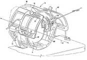
- FIGS. 1-2are perspective views of an MRI imaging coil assembly, according to some embodiments of the present invention.
- FIG. 3is a perspective view of an MRI imaging coil assembly, according to some embodiments of the present invention.
- FIG. 4is a perspective view of an MRI imaging coil assembly, according to some embodiments of the present invention.
- FIG. 5is a perspective view of an MRI imaging coil assembly, according to some embodiments of the present invention.
- FIG. 6is a perspective view of an MRI imaging coil assembly, according to some embodiments of the present invention.
- FIG. 7is an partial exploded view of the MRI imaging coil assembly of FIG. 6 , illustrating the mounting configuration of the primary imaging coil thereof to a head support assembly.
- FIG. 8is a schematic illustration of movement directions for the primary and secondary imaging coils of the imaging coil assembly of FIG. 6 .
- FIGS. 9A-9Cillustrate exemplary types of locking members for securing the secondary imaging coil to the primary imaging coil in the imaging coil assembly of FIG. 6 , according to some embodiments of the present invention.
- FIG. 10is a side view of an MRI imaging coil assembly, according to some embodiments of the present invention.
- FIGS. 11A-11Billustrate an MRI imaging coil assembly, according to some embodiments of the present invention.
- spatially relative termssuch as “under”, “below”, “lower”, “over”, “upper” and the like, may be used herein for ease of description to describe one element or feature's relationship to another element(s) or feature(s) as illustrated in the figures. It will be understood that the spatially relative terms are intended to encompass different orientations of the device in use or operation in addition to the orientation depicted in the figures. For example, if the device in the figures is inverted, elements described as “under” or “beneath” other elements or features would then be oriented “over” the other elements or features. Thus, the exemplary term “under” can encompass both an orientation of “over” and “under”.
- the devicemay be otherwise oriented (rotated 90 degrees or at other orientations) and the spatially relative descriptors used herein interpreted accordingly.
- the terms “upwardly”, “downwardly”, “vertical”, “horizontal” and the likeare used herein for the purpose of explanation only unless specifically indicated otherwise.
- MRI compatiblemeans that a device is safe for use in an MRI environment and/or can operate as intended in an MRI environment, and, as such, if residing within the high-field strength region of the magnetic field, is typically made of a non-ferromagnetic MRI compatible material(s) suitable to reside and/or operate in a high magnetic field environment.
- gantryrefers to a patient support of an MRI scanner and may include the patient table or other structure.
- rodrefers to an elongate member with rigidity, such as a bolt, pin, screw, etc.
- a head engagement rodis an elongate member with sufficient structural rigidity to secure the head of a patient.
- Imaging coil assemblies according to embodiments of the present inventionfacilitate guiding and/or placing diagnostic or interventional devices and/or therapies to any desired internal region of the brain.
- imaging coil assemblies according to embodiments of the present inventionfacilitate the placement of implantable DBS leads for brain stimulation, typically deep brain stimulation, and facilitate delivering tools or therapies that stimulate a desired region of the sympathetic nerve chain.
- Embodiments of the present inventioncan be used with any MRI scanner system, including open and closed bore designs and any field strength, typically 1.0 T-10 T.
- Embodiments of the present inventionhave other uses inside or outside the brain include stem cell placement, gene therapy or drug delivery for treating physiological conditions. Some embodiments can be used to treat tumors. Some embodiments can be used for diagnosing or delivering any desired therapy such as, for example, RF stimulation or ablation, laser stimulation or ablation, cryogenic stimulation or ablation, etc.
- a patient support surface 12such as a gantry associated with an MRI scanner, has a head support assembly 14 and an MRI imaging coil assembly 16 associated therewith.
- the head support assembly 14is configured to immobilize the head of a patient during an MRI-guided procedure, and includes a pair of elongated arms 18 , 20 that extend upwardly from the patient support surface 12 in adjacent, spaced-apart relationship to form a space for receiving the head of a patient.
- the illustrated arms 18 , 20lie in substantially the same plane (i.e., are substantially co-planar) and have an arcuate configuration.
- Each arm 18 , 20 of the head support assembly 14includes a respective free end 18 a , 20 a .
- a head engagement rod 22is adjustably associated near each respective arm free end 18 a , 20 a .
- the head engagement rods 22are configured to engage a patient's head within the head support assembly 14 .
- Embodiments of the present inventionare not limited to the illustrated head support assembly 14 .
- Head support assemblies utilized in conjunction with embodiments of the present inventioncan have various structural configurations, without limitation.
- exemplary head support assemblies that can be utilized with embodiments of the present inventionare described in copending U.S. patent application Ser. No. 12,237,091, filed Sep. 24, 2008, which is incorporated herein by reference in its entirety.
- an MRI imaging coil assembly 16that includes a primary external imaging coil 30 and a secondary external imaging coil 40 positioned proximate to the primary imaging coil 30 .
- the primary and secondary imaging coils 30 , 40cooperate to provide MRI signals to an MRI scanner.
- the primary imaging coil 30is configured to provide MRI signals to an MRI scanner of a target region of a patient's body, such as the brain.
- the secondary imaging coil 40provides MRI signals to an MRI scanner of an interventional device being utilized during an MRI-guided procedure.
- an image produced by the MRI imaging coil assembly 16has no greater than one-hundred percent (100%) difference in signal-to-noise ratio (SNR) across a volume thereof.
- SNRsignal-to-noise ratio
- the primary imaging coil 30can be secured to the head support assembly 14 and is configured to surround at least a portion of the head H of a patient.
- embodiments of the present inventiondo not require the primary imaging coil 30 to be secured to the head support assembly 14 .
- the primary imaging coil 30can be supported/secured in various ways and to other portions of an MRI scanner apparatus (e.g., to the gantry, to a base attached to the gantry etc.)
- the primary imaging coil 30has a plurality of spaced-apart RF coils, along with circuitry associated therewith.
- the RF coils within the primary head coil 30can be positioned as desired relative to a patient's head.
- An exemplary supplier of RF coils that may be utilizedis Midwest RF, LLC., Hartland, Wis.
- Embodiments of the present inventionare not limited to the illustrated configuration of the primary imaging coil 30 . Other configurations, such as illustrated in FIGS. 5-9 and 11 , may be utilized. In each of the illustrated embodiments, the RF coils within the primary imaging coils can be positioned as desired relative to a patient's head.
- the secondary imaging coil 40is positioned at one end of the primary imaging coil 30 , as illustrated in the figures, and has at least one RF coil.
- the secondary imaging coil 40is secured to the patient support surface 12 via mount 42 .
- the secondary imaging coil 40 illustrated in FIGS. 1-2has a substantially planar configuration and is oriented such that a plane defined thereby is substantially transverse to longitudinal axis A 1 defined by the primary imaging coil 30 .
- the secondary imaging coil mount 42allows the secondary imaging coil 40 to be positioned proximate to the primary imaging coil 30 along the axis A 1 and along directions D 1 and D 2 .
- the secondary imaging coil 40may be movable within the mount 42 (or the mount 42 may be movable) along direction D 1 .
- the secondary imaging coil 40may be raised and lowered within the mount 42 (or the mount 42 may be raised and lowered) along direction D 2 .
- mount 42may be movably positioned proximate to the primary imaging coil 30 along axis A 1 .
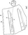
- FIG. 2illustrates the MRI-guided interventional system 10 of FIG. 1 with a patient's head H secured within the head support assembly 14 and with a trajectory or targeting frame 100 secured to the skull of the patient.
- the targeting frame 100supports a cooperating targeting cannula 110 that is configured to guide placement of an interventional device through a burr hole in the skull of the patient in vivo.
- the frame 100is adjustable such that the targeting cannula 110 is rotatable about a pitch axis, about a roll axis, and such that the targeting cannula can translate in X-Y directions.
- An exemplary targeting frameis described in U.S. patent application Ser. No. 12/134,412, filed Jun. 6, 2008, which is incorporated herein by reference in its entirety.
- the secondary MRI imaging coil 40may be focused to the targeting frame 100 , to the targeting cannula 110 , and/or to an interventional device 112 extending through the targeting cannula 110 and into the patient.
- the secondary MRI imaging coil 40may be focused on a subset of a volume of intrabody region of a patient (e.g., a patient's STN or other target deep brain region).
- FIG. 3illustrates an MRI imaging coil assembly 16 according to another embodiment of the present invention.
- the illustrated MRI imaging coil assembly 16includes a primary external MRI imaging coil 30 and a pair of secondary external MRI imaging coils 40 ′ positioned proximate to the primary MRI imaging coil 30 .
- the secondary imaging coils 40 ′are movably secured to the primary imaging coil 30 in adjacent, spaced-apart relationship, as illustrated.
- the secondary imaging coils 40 ′can have an arcuate shape and are configured to slide telescopically along the outer periphery of the primary imaging coil 30 .
- Each secondary imaging coil 40 ′includes a pair of spaced-apart slots 52 that engage respective locking members 54 . Locking members 54 can be loosened to permit the secondary imaging coils 40 ′ to move along the axial direction A 1 and can be tightened to secure the secondary imaging coils 40 ′ in a desired location.
- FIG. 4illustrates an MRI imaging coil assembly 16 according to another embodiment of the present invention.
- the illustrated MRI imaging coil assembly 16includes a primary external MRI imaging coil 30 and a secondary external MRI imaging coil 40 ′′ positioned proximate to the primary MRI imaging coil 30 .
- the secondary imaging coil 40 ′′is movably secured to the primary imaging coil 30 , as illustrated.
- the secondary imaging coil 40 ′′has an arcuate shape and is configured to slide telescopically along the outer periphery of the primary imaging coil 30 .
- the secondary imaging coil 40 ′′includes a pair of spaced-apart slots 52 that engage respective locking members 54 . Locking members 54 can be loosened to permit the secondary imaging coil 40 ′′ to move along the axial direction A 1 and can be tightened to secure the secondary imaging coil 40 ′′ in a desired location.
- FIG. 5illustrates an MRI imaging coil assembly 16 according to another embodiment of the present invention.
- the illustrated MRI imaging coil assembly 16includes a primary external MRI imaging coil 30 ′ and a secondary external MRI imaging coil 40 ′′′ positioned proximate to the primary MRI imaging coil 30 ′.
- the secondary imaging coil 40 ′′′is movably secured to the patient support surface 12 via a mount 42 ′, as illustrated.
- the secondary imaging coil 40 ′′′can have an arcuate shape and is configured to move along a direction D 1 that is transverse to an axial direction A 1 defined by the primary imaging coil 40 ′.
- the patient support surface 12includes a slot 44 within which mount 42 ′ slidably engages.
- the primary imaging coil 30 ′has an open-face, substantially U-shaped configuration with spaced-apart leg portions 30 a , 30 b having free ends.
- the primary imaging coil 30 ′is configured to be secured to the patient support surface 12 , or to a base attached to the patient support surface 12 , between the head support arms of a head support assembly (e.g., arms 18 , 20 of head support assembly 14 illustrated in FIGS. 1-4 ) such that the free ends of the leg portions 30 a , 30 b extend upwardly.
- a head support assemblye.g., arms 18 , 20 of head support assembly 14 illustrated in FIGS. 1-4
- FIGS. 6-8illustrate an MRI imaging coil assembly 16 according to is another embodiment of the present invention.
- the illustrated MRI imaging coil assembly 16includes a primary external MRI imaging coil 30 ′′ and a secondary external MRI imaging coil 40 ′′′′ positioned proximate to the primary MRI imaging coil 30 ′′.
- the secondary imaging coil 40 ′′′′can have an arcuate shape and is configured to slide telescopically along the inner periphery of the primary imaging coil 30 ′′.
- the secondary imaging coil 40 ′′′′can include a pair of spaced-apart slots 52 that engage respective locking members 54 . Locking members 54 can be loosened to permit the secondary imaging coil 40 ′′ to move along the axial direction A 1 and can be tightened to secure the secondary imaging coil 40 ′′′′ in a desired location.
- FIGS. 9A-9Cillustrate exemplary types of locking members 54 (e.g., clamping devices FIG. 9A , threaded devices FIG. 98 , and pull up devices FIG. 9C ) for securing the secondary imaging coil 40 ′′′′ to the primary imaging coil 30 ′′.
- locking members 54e.g., clamping devices FIG. 9A , threaded devices FIG. 98 , and pull up devices FIG. 9C .
- the illustrated primary imaging coil 30 ′′has an open-face, substantially U-shaped configuration with spaced-apart leg portions 30 a , 30 b having free ends.
- the primary imaging coil 30 ′′is configured to be secured to the head support assembly 14 via head engagement rods 22 that are adjustably associated with each respective arm 18 , 20 , as illustrated in FIG. 7 .
- Each head engagement rod 22is inserted through a grommet 24 that is configured to cooperate with a respective opposing slot 32 in the primary imaging coil 30 ′′.
- the grommets 24allow the primary imaging coil 30 ′′ to move along an axial direction A 1 relative to the head of a patient secured to the head support assembly 14 .
- FIG. 8illustrates directional movement of the primary and secondary imaging coils 30 ′′ and 40 ′′′′.
- Vertical movement of the primary and secondary imaging coils 30 ′′ and 40 ′′′′i.e., movement along direction D 2
- FIG. 10illustrates an MRI imaging coil assembly 16 according to another embodiment of the present invention.
- the illustrated MRI imaging coil assembly 16includes a primary external MRI imaging coil 30 ′ and a secondary external MRI imaging coil 140 secured to a targeting frame 100 and positioned proximate to the primary MRI imaging coil 30 ′.
- the secondary imaging coil 140 ′can have, but is not limited to, an oval shape. This secondary imaging coil 140 can be described as a local imaging coil focused to the frame 100 , burr hole or is other “local” view, rather that the entire head H.
- the secondary imaging coil 140 ′is attached directly to the targeting frame 100 (e.g., via threaded fasteners, etc.).
- the secondary imaging coil 140 ′may have various shapes and sizes.
- the MRI imaging coil assembly 16includes a primary external imaging coil 30 and a secondary external imaging coil 40 positioned proximate to the primary imaging coil 30 .
- the primary imaging coil 30has a plurality of spaced-apart RF coils, along with circuitry for controlling RF excitation of the RF coils.
- the secondary imaging coil 40has at least one RF coil, and is secured to the primary imaging coil 30 so as to overlie only a portion of the face of a patient.
- the secondary imaging coil 40can be about three inches (3′′) wide so as to cover from just below the nose of a patient to the patient's eyebrow.
- embodiments of the present inventionare not limited to a particular width of the secondary imaging coil 40 .
- the secondary imaging coil 40can have various widths, as well as various shapes and configurations.
- the secondary imaging coil 40need not be arcuate.
- the primary and secondary imaging coils 30 , 40cooperate to provide MRI signals to an MRI scanner.
- the illustrated secondary imaging coil 40is arcuate in shape and is secured to the free ends of the leg portions 30 a , 30 b of the primary imaging coil.
- the secondary imaging coil 40may be hingedly attached to one of the leg portions 30 a , 30 b of the primary imaging coil 30 .
- the secondary imaging coil 40may be removably secured to the primary imaging coil 30 .
- the secondary imaging coil 40may be movably secured to the leg portions 30 a , 30 b of the primary imaging coil 30 , and configured to slide along a longitudinal direction defined by the primary imaging coil.
- the secondary imaging coilmay be integral with the primary imaging coil 30 .
- the primary and secondary imaging coils 30 , 40can be a unitary apparatus.
- All of the components associated with the various head coil assemblies described aboveare formed from or include MRI-compatible material.
- MRI-compatible materialsinclude, but are not limited to, various polymeric materials (e.g., plastics), carbon fiber materials, glass-filled epoxies, and metals such as nickel-titanium alloys (e.g., Nitinol).
- polymeric materialse.g., plastics
- carbon fiber materialse.g., carbon fiber materials
- glass-filled epoxiese.g., aluminum-filled epoxies
- metalssuch as nickel-titanium alloys (e.g., Nitinol).
- Nitinolis non-ferromagnetic with a lower magnetic susceptibility than conventional stainless steel.
Landscapes
- Health & Medical Sciences (AREA)
- Physics & Mathematics (AREA)
- Life Sciences & Earth Sciences (AREA)
- Surgery (AREA)
- General Health & Medical Sciences (AREA)
- Engineering & Computer Science (AREA)
- Condensed Matter Physics & Semiconductors (AREA)
- General Physics & Mathematics (AREA)
- Nuclear Medicine, Radiotherapy & Molecular Imaging (AREA)
- Pathology (AREA)
- Molecular Biology (AREA)
- Biomedical Technology (AREA)
- Heart & Thoracic Surgery (AREA)
- Medical Informatics (AREA)
- Animal Behavior & Ethology (AREA)
- Public Health (AREA)
- Veterinary Medicine (AREA)
- Robotics (AREA)
- Biophysics (AREA)
- Radiology & Medical Imaging (AREA)
- High Energy & Nuclear Physics (AREA)
- Oral & Maxillofacial Surgery (AREA)
- Magnetic Resonance Imaging Apparatus (AREA)
Abstract
Description
Claims (25)
Priority Applications (1)
| Application Number | Priority Date | Filing Date | Title |
|---|---|---|---|
| US12/237,102US7602190B2 (en) | 2007-09-24 | 2008-09-24 | External MRI imaging coil assemblies and MRI-guided interventional systems utilizing same |
Applications Claiming Priority (3)
| Application Number | Priority Date | Filing Date | Title |
|---|---|---|---|
| US97482107P | 2007-09-24 | 2007-09-24 | |
| US12/134,412US8175677B2 (en) | 2007-06-07 | 2008-06-06 | MRI-guided medical interventional systems and methods |
| US12/237,102US7602190B2 (en) | 2007-09-24 | 2008-09-24 | External MRI imaging coil assemblies and MRI-guided interventional systems utilizing same |
Publications (2)
| Publication Number | Publication Date |
|---|---|
| US20090079431A1 US20090079431A1 (en) | 2009-03-26 |
| US7602190B2true US7602190B2 (en) | 2009-10-13 |
Family
ID=40515033
Family Applications (4)
| Application Number | Title | Priority Date | Filing Date |
|---|---|---|---|
| US12/134,412Active2031-02-17US8175677B2 (en) | 2007-06-07 | 2008-06-06 | MRI-guided medical interventional systems and methods |
| US12/237,033Active2030-05-22US8208993B2 (en) | 2007-06-07 | 2008-09-24 | Imaging device for MRI-guided medical interventional systems |
| US12/237,102Expired - Fee RelatedUS7602190B2 (en) | 2007-09-24 | 2008-09-24 | External MRI imaging coil assemblies and MRI-guided interventional systems utilizing same |
| US12/237,075Active2030-12-31US9097756B2 (en) | 2007-09-24 | 2008-09-24 | Control unit for MRI-guided medical interventional systems |
Family Applications Before (2)
| Application Number | Title | Priority Date | Filing Date |
|---|---|---|---|
| US12/134,412Active2031-02-17US8175677B2 (en) | 2007-06-07 | 2008-06-06 | MRI-guided medical interventional systems and methods |
| US12/237,033Active2030-05-22US8208993B2 (en) | 2007-06-07 | 2008-09-24 | Imaging device for MRI-guided medical interventional systems |
Family Applications After (1)
| Application Number | Title | Priority Date | Filing Date |
|---|---|---|---|
| US12/237,075Active2030-12-31US9097756B2 (en) | 2007-09-24 | 2008-09-24 | Control unit for MRI-guided medical interventional systems |
Country Status (6)
| Country | Link |
|---|---|
| US (4) | US8175677B2 (en) |
| EP (4) | EP2192870A1 (en) |
| JP (1) | JP5632286B2 (en) |
| CN (1) | CN101918855B (en) |
| CA (4) | CA2700529A1 (en) |
| WO (4) | WO2009042131A1 (en) |
Cited By (19)
| Publication number | Priority date | Publication date | Assignee | Title |
|---|---|---|---|---|
| US20080306375A1 (en)* | 2007-06-07 | 2008-12-11 | Surgi-Vision, Inc. | Mri-guided medical interventional systems and methods |
| US20090112084A1 (en)* | 2007-06-07 | 2009-04-30 | Surgi-Vision, Inc. | Mri-guided medical interventional systems and methods |
| US20090171184A1 (en)* | 2007-09-24 | 2009-07-02 | Surgi-Vision | Mri surgical systems for real-time visualizations using mri image data and predefined data of surgical tools |
| US20100315085A1 (en)* | 2009-06-16 | 2010-12-16 | Brian Brown | Modular Apparatus for Magnetic Resonance Imaging |
| US8369930B2 (en) | 2009-06-16 | 2013-02-05 | MRI Interventions, Inc. | MRI-guided devices and MRI-guided interventional systems that can track and generate dynamic visualizations of the devices in near real time |
| KR20140040058A (en)* | 2012-09-25 | 2014-04-02 | 지멘스 악티엔게젤샤프트 | Receiving coil for magnetic resonance system |
| US8979871B2 (en) | 2009-08-13 | 2015-03-17 | Monteris Medical Corporation | Image-guided therapy of a tissue |
| US9192446B2 (en) | 2012-09-05 | 2015-11-24 | MRI Interventions, Inc. | Trajectory guide frame for MRI-guided surgeries |
| US9259290B2 (en) | 2009-06-08 | 2016-02-16 | MRI Interventions, Inc. | MRI-guided surgical systems with proximity alerts |
| US9333038B2 (en) | 2000-06-15 | 2016-05-10 | Monteris Medical Corporation | Hyperthermia treatment and probe therefore |
| US9433383B2 (en) | 2014-03-18 | 2016-09-06 | Monteris Medical Corporation | Image-guided therapy of a tissue |
| US9504484B2 (en) | 2014-03-18 | 2016-11-29 | Monteris Medical Corporation | Image-guided therapy of a tissue |
| US9615770B2 (en) | 2011-04-15 | 2017-04-11 | Neocoil, Llc | Pediatric imaging assembly |
| US10327830B2 (en) | 2015-04-01 | 2019-06-25 | Monteris Medical Corporation | Cryotherapy, thermal therapy, temperature modulation therapy, and probe apparatus therefor |
| US10512511B2 (en) | 2013-07-24 | 2019-12-24 | Centre For Surgical Invention And Innovation | Multi-function mounting interface for an image-guided robotic system and quick release interventional toolset |
| US10595744B2 (en) | 2014-02-14 | 2020-03-24 | MRI Interventions, Inc. | Surgical tool-positioning devices and related methods |
| US10675113B2 (en) | 2014-03-18 | 2020-06-09 | Monteris Medical Corporation | Automated therapy of a three-dimensional tissue region |
| US20220113360A1 (en)* | 2018-05-16 | 2022-04-14 | Viewray Technologies, Inc. | Resistive electromagnet systems and methods |
| US11925511B2 (en) | 2020-01-31 | 2024-03-12 | Clearpoint Neuro, Inc. | Surgical tool support systems including elongate support legs with adjustable lengths and related methods |
Families Citing this family (176)
| Publication number | Priority date | Publication date | Assignee | Title |
|---|---|---|---|---|
| US20040162637A1 (en) | 2002-07-25 | 2004-08-19 | Yulun Wang | Medical tele-robotic system with a master remote station with an arbitrator |
| US7813836B2 (en) | 2003-12-09 | 2010-10-12 | Intouch Technologies, Inc. | Protocol for a remotely controlled videoconferencing robot |
| US8077963B2 (en) | 2004-07-13 | 2011-12-13 | Yulun Wang | Mobile robot with a head-based movement mapping scheme |
| US9198728B2 (en) | 2005-09-30 | 2015-12-01 | Intouch Technologies, Inc. | Multi-camera mobile teleconferencing platform |
| US8849679B2 (en) | 2006-06-15 | 2014-09-30 | Intouch Technologies, Inc. | Remote controlled robot system that provides medical images |
| US9160783B2 (en) | 2007-05-09 | 2015-10-13 | Intouch Technologies, Inc. | Robot system that operates through a network firewall |
| CN101772642B (en)* | 2007-07-02 | 2015-06-17 | 博格华纳公司 | Inlet design for a pump assembly |
| US8195272B2 (en) | 2007-09-24 | 2012-06-05 | MRI Interventions, Inc. | MRI-compatible patches and methods for using the same |
| WO2009067205A1 (en)* | 2007-11-21 | 2009-05-28 | Surgi-Vision, Inc. | Methods, systems and computer program products for positioning a guidance apparatus relative to a patient |
| US10875182B2 (en) | 2008-03-20 | 2020-12-29 | Teladoc Health, Inc. | Remote presence system mounted to operating room hardware |
| US8179418B2 (en) | 2008-04-14 | 2012-05-15 | Intouch Technologies, Inc. | Robotic based health care system |
| US8170241B2 (en) | 2008-04-17 | 2012-05-01 | Intouch Technologies, Inc. | Mobile tele-presence system with a microphone system |
| US9193065B2 (en) | 2008-07-10 | 2015-11-24 | Intouch Technologies, Inc. | Docking system for a tele-presence robot |
| US9842192B2 (en) | 2008-07-11 | 2017-12-12 | Intouch Technologies, Inc. | Tele-presence robot system with multi-cast features |
| US8728092B2 (en) | 2008-08-14 | 2014-05-20 | Monteris Medical Corporation | Stereotactic drive system |
| US8747418B2 (en) | 2008-08-15 | 2014-06-10 | Monteris Medical Corporation | Trajectory guide |
| US20100063422A1 (en)* | 2008-09-08 | 2010-03-11 | Sunnybrook Health Sciences Center | Ultrasound therapy transducer head and ultrasound therapy system incorporating the same |
| US8320990B2 (en)* | 2008-09-12 | 2012-11-27 | MRI Interventions, Inc. | Intrabody MRI stacked flat loop antennas and related systems |
| US8340819B2 (en) | 2008-09-18 | 2012-12-25 | Intouch Technologies, Inc. | Mobile videoconferencing robot system with network adaptive driving |
| US8270698B2 (en)* | 2008-09-24 | 2012-09-18 | Merge Healthcare Incorporated | Anterior commissure and posterior commissure segmentation system and method |
| US8996165B2 (en) | 2008-10-21 | 2015-03-31 | Intouch Technologies, Inc. | Telepresence robot with a camera boom |
| US9138891B2 (en) | 2008-11-25 | 2015-09-22 | Intouch Technologies, Inc. | Server connectivity control for tele-presence robot |
| US8463435B2 (en) | 2008-11-25 | 2013-06-11 | Intouch Technologies, Inc. | Server connectivity control for tele-presence robot |
| US20100198052A1 (en)* | 2009-01-28 | 2010-08-05 | Kimble Jenkins | Mri-compatible articulating arms and related systems and methods |
| US8849680B2 (en) | 2009-01-29 | 2014-09-30 | Intouch Technologies, Inc. | Documentation through a remote presence robot |
| US20100217115A1 (en)* | 2009-02-25 | 2010-08-26 | Hushek Stephen G | Temperature sensing within a patient during mr imaging |
| CN201384493Y (en)* | 2009-03-12 | 2010-01-20 | 西门子迈迪特(深圳)磁共振有限公司 | Positioning device used for magnetic resonance system |
| US9232977B1 (en)* | 2009-03-27 | 2016-01-12 | Tausif-Ur Rehman | Instrument guiding device |
| WO2010110881A1 (en)* | 2009-03-27 | 2010-09-30 | Hetherington Hoby P | Improved transceiver apparatus, system, and methodology for superior in-vivo imaging of human anatomy |
| US8897920B2 (en) | 2009-04-17 | 2014-11-25 | Intouch Technologies, Inc. | Tele-presence robot system with software modularity, projector and laser pointer |
| GB0908787D0 (en) | 2009-05-21 | 2009-07-01 | Renishaw Plc | Head clamp for imaging and neurosurgery |
| GB0908784D0 (en)* | 2009-05-21 | 2009-07-01 | Renishaw Plc | Apparatus for imaging a body part |
| DE102009034312A1 (en)* | 2009-07-23 | 2011-01-27 | Martin Hempel | Protective housing for flexible MR coils |
| US9107575B2 (en)* | 2009-07-29 | 2015-08-18 | Mauna Kea Technologies | Apparatus and method for brain fiber bundle microscopy |
| US8384755B2 (en) | 2009-08-26 | 2013-02-26 | Intouch Technologies, Inc. | Portable remote presence robot |
| US11399153B2 (en) | 2009-08-26 | 2022-07-26 | Teladoc Health, Inc. | Portable telepresence apparatus |
| US9844414B2 (en)* | 2009-08-31 | 2017-12-19 | Gregory S. Fischer | System and method for robotic surgical intervention in a magnetic resonance imager |
| US20110098553A1 (en)* | 2009-10-28 | 2011-04-28 | Steven Robbins | Automatic registration of images for image guided surgery |
| US9864032B2 (en)* | 2010-01-05 | 2018-01-09 | National Health Research Institutes | Magnetic resonance imaging system |
| US20110187875A1 (en)* | 2010-02-04 | 2011-08-04 | Intouch Technologies, Inc. | Robot face used in a sterile environment |
| US11154981B2 (en) | 2010-02-04 | 2021-10-26 | Teladoc Health, Inc. | Robot user interface for telepresence robot system |
| US8670017B2 (en) | 2010-03-04 | 2014-03-11 | Intouch Technologies, Inc. | Remote presence system including a cart that supports a robot face and an overhead camera |
| EP2558876B1 (en) | 2010-04-14 | 2018-12-12 | Koninklijke Philips N.V. | Instrument guiding during magnetic resonance imaging |
| US10105485B2 (en) | 2010-04-16 | 2018-10-23 | MRI Interventions, Inc. | MRI surgical systems including MRI-compatible surgical cannulae for transferring a substance to and/or from a patient |
| US9814885B2 (en) | 2010-04-27 | 2017-11-14 | Medtronic, Inc. | Stimulation electrode selection |
| DE102010020152B4 (en)* | 2010-05-11 | 2013-10-24 | Siemens Aktiengesellschaft | Device with local coil arrangement and implantable device |
| US10343283B2 (en) | 2010-05-24 | 2019-07-09 | Intouch Technologies, Inc. | Telepresence robot system that can be accessed by a cellular phone |
| US10808882B2 (en) | 2010-05-26 | 2020-10-20 | Intouch Technologies, Inc. | Tele-robotic system with a robot face placed on a chair |
| DE102010023844A1 (en)* | 2010-06-15 | 2011-12-15 | Siemens Aktiengesellschaft | MR RF coils with modulable flexibility |
| JP6040151B2 (en)* | 2010-06-16 | 2016-12-07 | エーツー・サージカル | Method for determining access region from 3D patient image |
| US9264664B2 (en) | 2010-12-03 | 2016-02-16 | Intouch Technologies, Inc. | Systems and methods for dynamic bandwidth allocation |
| US12093036B2 (en) | 2011-01-21 | 2024-09-17 | Teladoc Health, Inc. | Telerobotic system with a dual application screen presentation |
| US8965579B2 (en) | 2011-01-28 | 2015-02-24 | Intouch Technologies | Interfacing with a mobile telepresence robot |
| US9323250B2 (en) | 2011-01-28 | 2016-04-26 | Intouch Technologies, Inc. | Time-dependent navigation of telepresence robots |
| US11482326B2 (en) | 2011-02-16 | 2022-10-25 | Teladog Health, Inc. | Systems and methods for network-based counseling |
| EP2675353A2 (en)* | 2011-02-17 | 2013-12-25 | MRI Interventions, Inc. | Thin-sleeve apparatus for reducing rf coupling of devices in mri environments |
| KR101875122B1 (en)* | 2011-02-25 | 2018-07-11 | 주식회사 칼라세븐 | A Light therapy system using sunlight |
| EP2494936A3 (en)* | 2011-03-03 | 2012-09-19 | Imris Inc. | MR compatible optical viewing device for use in the bore of an MR magnet |
| US9668710B2 (en)* | 2011-03-18 | 2017-06-06 | Koninklijke Philips N.V. | Tracking brain deformation during neurosurgery |
| EP2693972A4 (en)* | 2011-04-08 | 2014-11-05 | Monteris Medical Corp | Head fixation system and method |
| US8406890B2 (en)* | 2011-04-14 | 2013-03-26 | Medtronic, Inc. | Implantable medical devices storing graphics processing data |
| US10769739B2 (en) | 2011-04-25 | 2020-09-08 | Intouch Technologies, Inc. | Systems and methods for management of information among medical providers and facilities |
| US20140139616A1 (en) | 2012-01-27 | 2014-05-22 | Intouch Technologies, Inc. | Enhanced Diagnostics for a Telepresence Robot |
| US9098611B2 (en) | 2012-11-26 | 2015-08-04 | Intouch Technologies, Inc. | Enhanced video interaction for a user interface of a telepresence network |
| DE102011079565B4 (en)* | 2011-07-21 | 2022-09-15 | Siemens Healthcare Gmbh | Direct connection head coil with height adjustment for e.g. Bechterew patients |
| TWI442905B (en)* | 2011-09-30 | 2014-07-01 | Univ Nat Chiao Tung | Apparatus for locating the target of the stimulation |
| US8836751B2 (en) | 2011-11-08 | 2014-09-16 | Intouch Technologies, Inc. | Tele-presence system with a user interface that displays different communication links |
| JP6220345B2 (en)* | 2011-12-05 | 2017-10-25 | コーニンクレッカ フィリップス エヌ ヴェKoninklijke Philips N.V. | Surgical tool positioning and orientation during patient-specific port placement |
| RU2634296C2 (en)* | 2012-01-03 | 2017-10-24 | Конинклейке Филипс Н.В. | Device for position determination |
| TWI463964B (en)* | 2012-03-03 | 2014-12-11 | Univ China Medical | System and apparatus for an image guided navigation system in surgery |
| US8902278B2 (en) | 2012-04-11 | 2014-12-02 | Intouch Technologies, Inc. | Systems and methods for visualizing and managing telepresence devices in healthcare networks |
| US9251313B2 (en) | 2012-04-11 | 2016-02-02 | Intouch Technologies, Inc. | Systems and methods for visualizing and managing telepresence devices in healthcare networks |
| EP2666428B1 (en)* | 2012-05-21 | 2015-10-28 | Universität Bern | System and method for estimating the spatial position of a tool within an object |
| US9361021B2 (en) | 2012-05-22 | 2016-06-07 | Irobot Corporation | Graphical user interfaces including touchpad driving interfaces for telemedicine devices |
| WO2013176760A1 (en) | 2012-05-22 | 2013-11-28 | Intouch Technologies, Inc. | Graphical user interfaces including touchpad driving interfaces for telemedicine devices |
| US9192393B2 (en) | 2012-05-31 | 2015-11-24 | MRI Interventions, Inc. | MRI compatible surgical drills and related methods |
| US9498290B2 (en) | 2012-07-19 | 2016-11-22 | MRI Interventions, Inc. | Surgical navigation devices and methods |
| US9610048B2 (en) | 2012-08-09 | 2017-04-04 | MRI Interventions, Inc. | Fiber optic systems for MRI suites and related devices and methods |
| HK1211820A1 (en)* | 2012-08-24 | 2016-06-03 | University Of Houston | Robotic device and systems for image-guided and robot-assisted surgery |
| US10136955B2 (en)* | 2012-08-24 | 2018-11-27 | University Of Houston System | Robotic device for image-guided surgery and interventions |
| US10588597B2 (en)* | 2012-12-31 | 2020-03-17 | Intuitive Surgical Operations, Inc. | Systems and methods for interventional procedure planning |
| US9078588B2 (en) | 2013-03-08 | 2015-07-14 | MRI Interventions, Inc. | MRI compatible intrabody stylets and related methods and systems |
| CN105050525B (en)* | 2013-03-15 | 2018-07-31 | 直观外科手术操作公司 | Shape sensor system for tracking interventional instruments and method of use |
| US9600138B2 (en)* | 2013-03-15 | 2017-03-21 | Synaptive Medical (Barbados) Inc. | Planning, navigation and simulation systems and methods for minimally invasive therapy |
| US10274553B2 (en)* | 2013-03-15 | 2019-04-30 | Canon U.S.A., Inc. | Needle placement manipulator with attachment for RF-coil |
| US9730762B2 (en) | 2013-03-15 | 2017-08-15 | Neocoil, Llc | Automatic needle insertion location identification |
| US9222996B2 (en)* | 2013-03-15 | 2015-12-29 | The Brigham And Women's Hospital, Inc. | Needle placement manipulator with two rotary guides |
| US9782198B2 (en)* | 2013-03-28 | 2017-10-10 | Koninklijke Philips N.V. | Localization of robotic remote center of motion point using custom trocar |
| CN103340685A (en)* | 2013-06-27 | 2013-10-09 | 苏州边枫电子科技有限公司 | Auxiliary needle feeding device of pneumatic type puncture needle |
| US9600778B2 (en) | 2013-07-02 | 2017-03-21 | Surgical Information Sciences, Inc. | Method for a brain region location and shape prediction |
| US9891296B2 (en) | 2013-09-13 | 2018-02-13 | MRI Interventions, Inc. | Intrabody fluid transfer devices, systems and methods |
| CA2924230C (en)* | 2013-09-18 | 2020-03-31 | iMIRGE Medical INC. | Optical targeting and visusalization of trajectories |
| WO2015058815A1 (en)* | 2013-10-25 | 2015-04-30 | Brainlab Ag | Magnetic resonance coil unit and method for its manufacture |
| CN103646182B (en)* | 2013-12-13 | 2018-11-02 | 陕西理工学院 | A kind of application process of flexibility dynamic and visual technology on the medical image |
| JP6467434B2 (en) | 2014-02-27 | 2019-02-13 | ザ ブリガム アンド ウィメンズ ホスピタル インコーポレイテッドThe Brigham and Women’s Hospital, Inc. | Mounting device |
| US10251670B2 (en) | 2014-05-09 | 2019-04-09 | Canon U.S.A., Inc. | Positioning apparatus |
| BR112017004353A2 (en) | 2014-09-05 | 2017-12-05 | Hyperfine Res Inc | ferromagnetic magnification for magnetic resonance imaging |
| US10866291B2 (en)* | 2014-09-12 | 2020-12-15 | Emory University | Devices and systems for MRI-guided procedures |
| JP7045664B2 (en) | 2014-09-12 | 2022-04-01 | ザ ブリガム アンド ウィメンズ ホスピタル インコーポレイテッド | Needle positioning device |
| WO2016077417A1 (en) | 2014-11-11 | 2016-05-19 | Hyperfine Research, Inc. | Low field magnetic resonance methods and apparatus |
| HK1246815A1 (en) | 2015-01-16 | 2018-09-14 | Voyager Therapeutics, Inc. | Central nervous system targeting polynucleotides |
| US10542961B2 (en) | 2015-06-15 | 2020-01-28 | The Research Foundation For The State University Of New York | System and method for infrasonic cardiac monitoring |
| EP3316784B1 (en)* | 2015-06-30 | 2021-08-04 | Canon U.S.A., Inc. | Fiducial markers, systems, and methods of registration |
| US10420626B2 (en) | 2015-06-30 | 2019-09-24 | Canon U.S.A., Inc. | Fiducial markers, systems, and methods of registration |
| US9867673B2 (en) | 2015-07-14 | 2018-01-16 | Canon U.S.A, Inc. | Medical support device |
| US10639065B2 (en) | 2015-07-21 | 2020-05-05 | Canon U.S.A., Inc. | Medical assist device |
| US10324594B2 (en)* | 2015-10-30 | 2019-06-18 | Siemens Healthcare Gmbh | Enterprise protocol management |
| AU2016357286B2 (en)* | 2015-11-16 | 2021-10-14 | Think Surgical, Inc. | Method for confirming registration of tracked bones |
| US11990232B2 (en)* | 2015-11-30 | 2024-05-21 | Koninklijke Philips N.V. | Clinical discovery wheel—a system to explore clinical concepts |
| US10806523B2 (en)* | 2015-12-28 | 2020-10-20 | Xact Robotics Ltd. | Adjustable registration frame |
| USD824027S1 (en) | 2016-01-13 | 2018-07-24 | MRI Interventions, Inc. | Fins for a support column for a surgical trajectory frame |
| USD829904S1 (en) | 2016-01-13 | 2018-10-02 | MRI Interventions, Inc. | Curved bracket for surgical navigation systems |
| US10376333B2 (en) | 2016-01-14 | 2019-08-13 | MRI Interventions, Inc. | Devices for surgical navigation systems |
| WO2017132505A1 (en) | 2016-01-29 | 2017-08-03 | Canon U.S.A., Inc. | Tool placement manipulator |
| CN105726124B (en)* | 2016-02-06 | 2019-01-15 | 齐欣 | Near end of thighbone location of operation orientation system and preparation method thereof |
| EP3393571B1 (en) | 2016-02-17 | 2024-03-06 | ClearPoint Neuro, Inc. | Intrabody surgical fluid transfer assemblies with adjustable exposed cannula to needle tip length, related systems and methods |
| CN109106454B (en)* | 2016-05-31 | 2020-09-22 | 万伟东 | RC intracranial minimally invasive treatment positioning device |
| CN106175893B (en)* | 2016-08-03 | 2018-10-30 | 福建医科大学附属第一医院 | A kind of device of arching trajectory implantation intracranial electrode |
| CN106137283B (en)* | 2016-08-27 | 2018-08-17 | 天津大学 | A kind of natural cavity apparatus work rotary switch with regulatory function |
| DE102016216203A1 (en)* | 2016-08-29 | 2017-09-14 | Siemens Healthcare Gmbh | Medical imaging system |
| JP2019531787A (en) | 2016-08-30 | 2019-11-07 | ザ リージェンツ オブ ザ ユニバーシティ オブ カリフォルニア | Biomedical targeting and delivery method and apparatus and system for performing the same |
| JP6948389B2 (en) | 2016-10-19 | 2021-10-13 | キヤノン ユーエスエイ, インコーポレイテッドCanon U.S.A., Inc | Placement manipulators and attachments for positioning puncture devices |
| US10718842B2 (en) | 2016-11-22 | 2020-07-21 | Hyperfine Research, Inc. | Systems and methods for automated detection in magnetic resonance images |
| US10539637B2 (en) | 2016-11-22 | 2020-01-21 | Hyperfine Research, Inc. | Portable magnetic resonance imaging methods and apparatus |
| US10627464B2 (en) | 2016-11-22 | 2020-04-21 | Hyperfine Research, Inc. | Low-field magnetic resonance imaging methods and apparatus |
| US11842030B2 (en) | 2017-01-31 | 2023-12-12 | Medtronic Navigation, Inc. | Method and apparatus for image-based navigation |
| CN106618507A (en)* | 2017-03-13 | 2017-05-10 | 北京理工大学 | Touch cerebration stimulation device and fine adjustment assembly |
| AU2018235079B2 (en) | 2017-03-15 | 2022-12-08 | Orthotaxy | System for guiding a surgical tool relative to a target axis in spine surgery |
| US11571262B2 (en)* | 2017-04-18 | 2023-02-07 | Intuitive Surgical Operations, Inc. | Graphical user interface for planning a procedure |
| US11862302B2 (en) | 2017-04-24 | 2024-01-02 | Teladoc Health, Inc. | Automated transcription and documentation of tele-health encounters |
| EP4018946A1 (en) | 2017-05-03 | 2022-06-29 | Medtronic Vascular, Inc. | Tissue-removing catheter |
| US11690645B2 (en) | 2017-05-03 | 2023-07-04 | Medtronic Vascular, Inc. | Tissue-removing catheter |
| US10548674B2 (en)* | 2017-07-06 | 2020-02-04 | YellowDot Innovations, LLC | Robotic guide for medical device |
| CN111132626B (en)* | 2017-07-17 | 2024-01-30 | 沃雅戈治疗公司 | track array guidance system |
| US10483007B2 (en) | 2017-07-25 | 2019-11-19 | Intouch Technologies, Inc. | Modular telehealth cart with thermal imaging and touch screen user interface |
| MX2020001187A (en) | 2017-08-03 | 2020-10-05 | Voyager Therapeutics Inc | Compositions and methods for delivery of aav. |
| US11202652B2 (en) | 2017-08-11 | 2021-12-21 | Canon U.S.A., Inc. | Registration and motion compensation for patient-mounted needle guide |
| US10987016B2 (en)* | 2017-08-23 | 2021-04-27 | The Boeing Company | Visualization system for deep brain stimulation |
| US11636944B2 (en) | 2017-08-25 | 2023-04-25 | Teladoc Health, Inc. | Connectivity infrastructure for a telehealth platform |
| CN109620407B (en)* | 2017-10-06 | 2024-02-06 | 皇家飞利浦有限公司 | Treatment trajectory guidance system |
| US10893911B2 (en) | 2017-11-26 | 2021-01-19 | Canon U.S.A., Inc. | Automated image cropping for enhanced automatic device-to-image registration |
| WO2019168973A1 (en)* | 2018-02-27 | 2019-09-06 | The Regents Of The University Of Colorado, A Body Corporate | Robotic stereotaxic platform with computer vision |
| FR3078879B1 (en)* | 2018-03-14 | 2020-03-06 | Assistance Publique Hopitaux De Paris | SURGICAL KIT TO BE USED DURING A CRANIECTOMY PROCEDURE |
| US10617299B2 (en) | 2018-04-27 | 2020-04-14 | Intouch Technologies, Inc. | Telehealth cart that supports a removable tablet with seamless audio/video switching |
| US11253237B2 (en) | 2018-05-09 | 2022-02-22 | Clearpoint Neuro, Inc. | MRI compatible intrabody fluid transfer systems and related devices and methods |
| EP3781074A1 (en) | 2018-05-09 | 2021-02-24 | ClearPoint Neuro, Inc. | Mri compatible intrabody fluid transfer systems and related devices and methods |
| BR112020023082A2 (en) | 2018-05-15 | 2021-02-09 | Voyager Therapeutics, Inc. | compositions and methods for the treatment of parkinson's disease |
| EP3793616A1 (en) | 2018-05-15 | 2021-03-24 | Voyager Therapeutics, Inc. | Compositions and methods for delivery of aav |
| WO2019222444A2 (en) | 2018-05-16 | 2019-11-21 | Voyager Therapeutics, Inc. | Directed evolution |
| CN108814658B (en)* | 2018-06-27 | 2021-10-01 | 中国人民解放军陆军军医大学第三附属医院(野战外科研究所) | A craniotomy device and craniotomy method |
| EP3826719A1 (en) | 2018-07-24 | 2021-06-02 | Voyager Therapeutics, Inc. | Systems and methods for producing gene therapy formulations |
| WO2020077165A1 (en) | 2018-10-12 | 2020-04-16 | Voyager Therapeutics, Inc. | Compositions and methods for delivery of aav |
| CN118697424A (en) | 2018-11-16 | 2024-09-27 | 美敦力瓦斯科尔勒公司 | Tissue Removal Catheter |
| US11744655B2 (en) | 2018-12-04 | 2023-09-05 | Globus Medical, Inc. | Drill guide fixtures, cranial insertion fixtures, and related methods and robotic systems |
| US11406470B2 (en) | 2019-02-01 | 2022-08-09 | Advanced Neuromodulation Systems, Inc. | Trajectory guide with double X-Y sliding tables |
| US11364086B2 (en) | 2019-02-01 | 2022-06-21 | Advanced Neuromodulation Systems, Inc. | Trajectory guide with dual arc arrangement |
| US11298204B2 (en) | 2019-02-01 | 2022-04-12 | Advanced Neuromodulation Systems, Inc. | Trajectory guide with dual gimbal drive arrangement |
| CA3159100A1 (en) | 2019-03-25 | 2020-10-01 | Promaxo, Inc. | Single-sided fast mri gradient field coils and applications thereof |
| US11819236B2 (en) | 2019-05-17 | 2023-11-21 | Medtronic Vascular, Inc. | Tissue-removing catheter |
| US20220333133A1 (en) | 2019-09-03 | 2022-10-20 | Voyager Therapeutics, Inc. | Vectorized editing of nucleic acids to correct overt mutations |
| US11684750B2 (en) | 2019-10-08 | 2023-06-27 | Clearpoint Neuro, Inc. | Extension tube assembly and related medical fluid transfer systems and methods |
| US11925418B2 (en) | 2019-12-02 | 2024-03-12 | The General Hospital Corporation | Methods for multi-modal bioimaging data integration and visualization |
| US20230056943A1 (en)* | 2019-12-13 | 2023-02-23 | Dinesh Vyas | Stapler apparatus and methods for use |
| JP7608463B2 (en) | 2019-12-19 | 2025-01-06 | クリアポイント ニューロ, インク. | FRONT LOADABLE FLUID TRANSFER ASSEMBLY AND ASSOCIATED MEDICAL FLUID TRANSFER SYSTEMS AND METHODS - Patent application |
| US11602400B2 (en)* | 2020-01-10 | 2023-03-14 | Stryker European Operations Limited | Surgical arm and method of providing visual guidance for operating same |
| WO2021183295A2 (en)* | 2020-03-12 | 2021-09-16 | Clearpoint Neuro, Inc. | Image-guided surgical systems with automated trajectory guide systems and related devices and methods |
| WO2021221929A1 (en) | 2020-04-30 | 2021-11-04 | Clearpoint Neuro, Inc. | Surgical planning systems that automatically assess different potential trajectory paths and identify candidate trajectories for surgical systems |
| TWI737404B (en) | 2020-07-15 | 2021-08-21 | 臺北醫學大學 | Medical image processing system and method thereof |
| CN113940754B (en)* | 2020-07-15 | 2024-03-22 | 台北医学大学 | Medical image processing system and method |
| US11238591B1 (en) | 2020-07-15 | 2022-02-01 | Taipei Medical University (Tmu) | Medical image processing system and method thereof |
| US20220296308A1 (en)* | 2021-03-16 | 2022-09-22 | Clearpoint Neuro, Inc. | Directional-device intrabody placement systems and related methods |
| US20240358399A1 (en)* | 2021-03-31 | 2024-10-31 | Clear Guide Medical, Inc. | System and method for image guided interventions |
| CN113764074B (en)* | 2021-09-13 | 2024-01-02 | 杭州太美星程医药科技有限公司 | Image processing method and device, computer equipment and storage medium |
| DE102022125703A1 (en)* | 2022-10-05 | 2024-04-11 | Otto-von-Guericke-Universität Magdeburg, Körperschaft des öffentlichen Rechts | COUPLING STATION AND REMOTE MANIPULATION SYSTEM |
| CN116549069B (en)* | 2023-04-25 | 2024-07-02 | 苏州新云医疗设备有限公司 | Medical stabilizer |
| CN117860380B (en)* | 2024-03-11 | 2024-07-30 | 北京壹点灵动科技有限公司 | Data processing method and device for knee joint replacement, storage medium and electronic equipment |
Citations (16)
| Publication number | Priority date | Publication date | Assignee | Title |
|---|---|---|---|---|
| US5085219A (en)* | 1987-10-30 | 1992-02-04 | The Regents Of The University Of California | Adjustable holders for magnetic reasonance imaging rf surface coil |
| WO1997035206A1 (en) | 1996-03-15 | 1997-09-25 | National Research Council Of Canada | Surgical procedure with magnetic resonance imaging |
| WO1998052064A1 (en) | 1997-05-15 | 1998-11-19 | Regents Of The University Of Minnesota | Method and apparatus for targeted drug delivery into a living patient using magnetic resonance imaging |
| US6177797B1 (en) | 1996-12-19 | 2001-01-23 | Advanced Imaging Research, Inc. | Radio-frequency coil and method for resonance/imaging analysis |
| US6198961B1 (en)* | 1998-11-12 | 2001-03-06 | Picker International, Inc. | Interventional radio frequency coil assembly for magnetic resonance (MR) guided neurosurgery |
| US6198962B1 (en)* | 1998-11-25 | 2001-03-06 | Toshiba America Mri, Inc. | Quadrature detection coil for interventional MRI |
| DE10029736A1 (en) | 2000-06-23 | 2002-01-03 | Daum Gmbh I Ins | Minimally invasive neurosurgery insert is small clamped by |
| US20020049451A1 (en) | 2000-08-17 | 2002-04-25 | Kari Parmer | Trajectory guide with instrument immobilizer |
| US20020052610A1 (en) | 2000-04-07 | 2002-05-02 | Skakoon James G. | Deep organ access device and method |
| WO2002039135A2 (en) | 2000-11-09 | 2002-05-16 | Philips Medical Systems (Cleveland), Inc. | Mri rf coil systems having detachable, relocatable, and/or interchangeable sections and mri imaging systems and methods employing the same |
| US20020190716A1 (en) | 1998-11-25 | 2002-12-19 | Misic George J. | Multimode operation of quadrature phased array MR coil systems |
| US6577888B1 (en) | 2000-09-29 | 2003-06-10 | Usa Instruments, Inc. | Sliding-dome and split-top MRI radio frequency quadrature array coil system |
| WO2003102614A1 (en) | 2002-05-29 | 2003-12-11 | Surgi-Vision, Inc. | Magnetic resonance probes |
| US20040215279A1 (en) | 2003-04-25 | 2004-10-28 | Houben Richard P.M. | Implantable lead-based sensor powered by piezoelectric transformer |
| US20040228796A1 (en) | 2001-10-19 | 2004-11-18 | Scimed Life Systems, Inc. | Magnetic resonance imaging devices with a contrast medium for improved imaging |
| DE102005062716A1 (en) | 2005-12-28 | 2007-07-05 | Precisis Ag | Stereotaxis system for neurosurgical procedures with minimal image disturbances and optimal handling |
Family Cites Families (128)
| Publication number | Priority date | Publication date | Assignee | Title |
|---|---|---|---|---|
| US2697433A (en) | 1951-12-04 | 1954-12-21 | Max A Zehnder | Device for accurately positioning and guiding guide wires used in the nailing of thefemoral neck |
| US3878830A (en)* | 1973-05-31 | 1975-04-22 | Mediscience Technology Corp | Catheter system for blood gas monitoring |
| US4051845A (en)* | 1976-03-05 | 1977-10-04 | The Kendall Company | Drape assembly with pouch and method |
| US4386602A (en) | 1977-05-17 | 1983-06-07 | Sheldon Charles H | Intracranial surgical operative apparatus |
| US4209258A (en)* | 1978-02-14 | 1980-06-24 | Oakes W Peter | Automatic continuous mixer apparatus |
| US4319136A (en) | 1979-11-09 | 1982-03-09 | Jinkins J Randolph | Computerized tomography radiograph data transfer cap |
| US4276697A (en)* | 1980-04-21 | 1981-07-07 | Astek Engineering, Inc. | Compliance element for remote center compliance unit |
| US4838265A (en) | 1985-05-24 | 1989-06-13 | Cosman Eric R | Localization device for probe placement under CT scanner imaging |
| DE3804491A1 (en)* | 1987-12-02 | 1989-06-15 | Olympus Optical Co | Device for brain surgery |
| JPH0252642A (en) | 1988-08-17 | 1990-02-22 | Olympus Optical Co Ltd | Brain operation equipment |
| JPH0298335A (en)* | 1988-10-04 | 1990-04-10 | Toshiba Corp | Treatment location positioning mechanism for magnetic resonance imaging |
| US5125888A (en) | 1990-01-10 | 1992-06-30 | University Of Virginia Alumni Patents Foundation | Magnetic stereotactic system for treatment delivery |
| US6006126A (en) | 1991-01-28 | 1999-12-21 | Cosman; Eric R. | System and method for stereotactic registration of image scan data |
| JPH0584309A (en) | 1991-09-27 | 1993-04-06 | Olympus Optical Co Ltd | Water supply connector device of medical instrument |
| US5469847A (en) | 1992-09-09 | 1995-11-28 | Izi Corporation | Radiographic multi-modality skin markers |
| US5342356A (en) | 1992-12-02 | 1994-08-30 | Ellman Alan G | Electrical coupling unit for electrosurgery |
| US5799099A (en)* | 1993-02-12 | 1998-08-25 | George S. Allen | Automatic technique for localizing externally attached fiducial markers in volume images of the head |
| US6419680B1 (en) | 1993-06-10 | 2002-07-16 | Sherwood Services Ag | CT and MRI visible index markers for stereotactic localization |
| US5469353A (en)* | 1993-11-26 | 1995-11-21 | Access Radiology Corp. | Radiological image interpretation apparatus and method |
| US5450293A (en)* | 1993-12-30 | 1995-09-12 | Hoffman; Elliott S. | Finger mounted fiber optic illumination system |
| US5537704A (en)* | 1994-07-19 | 1996-07-23 | Ohio Medical Instrument Company, Inc. | Radiolucent head clamp |
| DE69531994T2 (en)* | 1994-09-15 | 2004-07-22 | OEC Medical Systems, Inc., Boston | SYSTEM FOR POSITION DETECTION BY MEANS OF A REFERENCE UNIT ATTACHED TO A PATIENT'S HEAD FOR USE IN THE MEDICAL AREA |
| US5728079A (en) | 1994-09-19 | 1998-03-17 | Cordis Corporation | Catheter which is visible under MRI |
| US5695501A (en) | 1994-09-30 | 1997-12-09 | Ohio Medical Instrument Company, Inc. | Apparatus for neurosurgical stereotactic procedures |
| US5971997A (en)* | 1995-02-03 | 1999-10-26 | Radionics, Inc. | Intraoperative recalibration apparatus for stereotactic navigators |
| US5971984A (en) | 1995-03-01 | 1999-10-26 | Smith & Nephew, Inc. | Method of using an orthopaedic fixation device |
| US5699801A (en) | 1995-06-01 | 1997-12-23 | The Johns Hopkins University | Method of internal magnetic resonance imaging and spectroscopic analysis and associated apparatus |
| US5697958A (en) | 1995-06-07 | 1997-12-16 | Intermedics, Inc. | Electromagnetic noise detector for implantable medical devices |
| US5638819A (en) | 1995-08-29 | 1997-06-17 | Manwaring; Kim H. | Method and apparatus for guiding an instrument to a target |
| US5855582A (en) | 1995-12-19 | 1999-01-05 | Gildenberg; Philip L. | Noninvasive stereotactic apparatus and method for relating data between medical devices |
| US5800353A (en)* | 1996-02-12 | 1998-09-01 | Mclaurin, Jr.; Robert L. | Automatic image registration of magnetic resonance imaging scans for localization, 3-dimensional treatment planning, and radiation treatment of abnormal lesions |
| US5928145A (en) | 1996-04-25 | 1999-07-27 | The Johns Hopkins University | Method of magnetic resonance imaging and spectroscopic analysis and associated apparatus employing a loopless antenna |
| US6263229B1 (en) | 1998-11-13 | 2001-07-17 | Johns Hopkins University School Of Medicine | Miniature magnetic resonance catheter coils and related methods |
| US6675033B1 (en) | 1999-04-15 | 2004-01-06 | Johns Hopkins University School Of Medicine | Magnetic resonance imaging guidewire probe |
| DE19618945C2 (en) | 1996-05-10 | 2003-02-27 | Phonak Ag Staefa | Fixable positioning system for a firm, play-free connection to the human skull |
| DE19625834A1 (en) | 1996-06-27 | 1998-01-02 | Siemens Ag | Medical system architecture |
| US5961455A (en) | 1996-12-31 | 1999-10-05 | Daum Gmbh | Device for positioning a medical instrument and method |
| US5993463A (en) | 1997-05-15 | 1999-11-30 | Regents Of The University Of Minnesota | Remote actuation of trajectory guide |
| US6752812B1 (en) | 1997-05-15 | 2004-06-22 | Regent Of The University Of Minnesota | Remote actuation of trajectory guide |
| US6267769B1 (en) | 1997-05-15 | 2001-07-31 | Regents Of The Universitiy Of Minnesota | Trajectory guide method and apparatus for use in magnetic resonance and computerized tomographic scanners |
| US6050992A (en) | 1997-05-19 | 2000-04-18 | Radiotherapeutics Corporation | Apparatus and method for treating tissue with multiple electrodes |
| SE9800126D0 (en) | 1998-01-20 | 1998-01-20 | Pacesetter Ab | Implantable medical device |
| US6360116B1 (en) | 1998-02-27 | 2002-03-19 | Varian Medical Systems, Inc. | Brachytherapy system for prostate cancer treatment with computer implemented systems and processes to facilitate pre-operative planning and post-operative evaluations |
| US6273896B1 (en) | 1998-04-21 | 2001-08-14 | Neutar, Llc | Removable frames for stereotactic localization |
| US6298262B1 (en) | 1998-04-21 | 2001-10-02 | Neutar, Llc | Instrument guidance for stereotactic surgery |
| US6546277B1 (en)* | 1998-04-21 | 2003-04-08 | Neutar L.L.C. | Instrument guidance system for spinal and other surgery |
| US6529765B1 (en) | 1998-04-21 | 2003-03-04 | Neutar L.L.C. | Instrumented and actuated guidance fixture for sterotactic surgery |
| FR2779339B1 (en) | 1998-06-09 | 2000-10-13 | Integrated Surgical Systems Sa | MATCHING METHOD AND APPARATUS FOR ROBOTIC SURGERY, AND MATCHING DEVICE COMPRISING APPLICATION |
| US6459927B1 (en) | 1999-07-06 | 2002-10-01 | Neutar, Llc | Customizable fixture for patient positioning |
| US6282437B1 (en) | 1998-08-12 | 2001-08-28 | Neutar, Llc | Body-mounted sensing system for stereotactic surgery |
| US6351662B1 (en) | 1998-08-12 | 2002-02-26 | Neutar L.L.C. | Movable arm locator for stereotactic surgery |
| US6117143A (en) | 1998-09-11 | 2000-09-12 | Hybex Surgical Specialties, Inc. | Apparatus for frameless stereotactic surgery |
| US6954802B2 (en)* | 1998-09-29 | 2005-10-11 | Tdk Electronics Corporation | Removable media recording station for the medical industry |
| US20050240445A1 (en) | 1998-09-29 | 2005-10-27 | Michael Sutherland | Medical archive library and method |
| US6195577B1 (en) | 1998-10-08 | 2001-02-27 | Regents Of The University Of Minnesota | Method and apparatus for positioning a device in a body |
| US7844319B2 (en) | 1998-11-04 | 2010-11-30 | Susil Robert C | Systems and methods for magnetic-resonance-guided interventional procedures |
| US6701176B1 (en) | 1998-11-04 | 2004-03-02 | Johns Hopkins University School Of Medicine | Magnetic-resonance-guided imaging, electrophysiology, and ablation |
| US6264607B1 (en)* | 1998-11-17 | 2001-07-24 | Metra Biosystems, Inc. | Test object geometry for ultrasound transmission calibration |
| US6284971B1 (en) | 1998-11-25 | 2001-09-04 | Johns Hopkins University School Of Medicine | Enhanced safety coaxial cables |
| US6470207B1 (en) | 1999-03-23 | 2002-10-22 | Surgical Navigation Technologies, Inc. | Navigational guidance via computer-assisted fluoroscopic imaging |
| US7848788B2 (en) | 1999-04-15 | 2010-12-07 | The Johns Hopkins University | Magnetic resonance imaging probe |
| US6491699B1 (en) | 1999-04-20 | 2002-12-10 | Surgical Navigation Technologies, Inc. | Instrument guidance method and system for image guided surgery |
| US6539263B1 (en) | 1999-06-11 | 2003-03-25 | Cornell Research Foundation, Inc. | Feedback mechanism for deep brain stimulation |
| US6167311A (en) | 1999-06-14 | 2000-12-26 | Electro Core Techniques, Llc | Method of treating psychological disorders by brain stimulation within the thalamus |
| US20030205233A1 (en)* | 1999-12-02 | 2003-11-06 | A-Med Systems, Inc. | Surgical drape and panel assembly |
| JP2001161660A (en) | 1999-12-10 | 2001-06-19 | Hitachi Medical Corp | Magnetic resonance imaging system |
| DK200001852A (en) | 1999-12-14 | 2001-06-15 | Asahi Optical Co Ltd | Manipulation section for an endoscopic treatment instrument |
| US6356786B1 (en) | 2000-01-20 | 2002-03-12 | Electrocore Techniques, Llc | Method of treating palmar hyperhydrosis by electrical stimulation of the sympathetic nervous chain |
| US6438423B1 (en) | 2000-01-20 | 2002-08-20 | Electrocore Technique, Llc | Method of treating complex regional pain syndromes by electrical stimulation of the sympathetic nerve chain |
| AU2001238012A1 (en) | 2000-02-01 | 2001-08-14 | Surgi-Vision, Inc. | Magnetic resonance imaging transseptal needle antenna |
| US6609030B1 (en) | 2000-02-24 | 2003-08-19 | Electrocore Techniques, Llc | Method of treating psychiatric diseases by neuromodulation within the dorsomedial thalamus |
| US6708064B2 (en) | 2000-02-24 | 2004-03-16 | Ali R. Rezai | Modulation of the brain to affect psychiatric disorders |
| US6725080B2 (en) | 2000-03-01 | 2004-04-20 | Surgical Navigation Technologies, Inc. | Multiple cannula image guided tool for image guided procedures |
| AU2001247806A1 (en) | 2000-03-24 | 2001-10-08 | Surgi-Vision | Endoluminal mri probe |
| US6477399B2 (en)* | 2000-03-29 | 2002-11-05 | Mcw Research Foundation, Inc. | Method for determining the reliability of fMRI parameters |
| DE10015670A1 (en)* | 2000-03-29 | 2001-10-11 | Forschungszentrum Juelich Gmbh | Head holder has arrangement for holding head in one position and at least three markers. whose positions can be freely selected in non-symmetrical arrangement with respect to each other |
| US6315783B1 (en)* | 2000-04-07 | 2001-11-13 | Odin Technologies, Ltd. | Surgical head support |
| US7366561B2 (en) | 2000-04-07 | 2008-04-29 | Medtronic, Inc. | Robotic trajectory guide |
| US6575904B2 (en)* | 2000-05-09 | 2003-06-10 | Matsushita Electric Industrial Co., Ltd. | Biodata interfacing system |
| US6526318B1 (en) | 2000-06-16 | 2003-02-25 | Mehdi M. Ansarinia | Stimulation method for the sphenopalatine ganglia, sphenopalatine nerve, or vidian nerve for treatment of medical conditions |
| DE10029737B4 (en) | 2000-06-23 | 2006-01-19 | Mri Devices Daum Gmbh | Navigation of a medical instrument |
| US6712773B1 (en) | 2000-09-11 | 2004-03-30 | Tyco Healthcare Group Lp | Biopsy system |
| US6405079B1 (en) | 2000-09-22 | 2002-06-11 | Mehdi M. Ansarinia | Stimulation method for the dural venous sinuses and adjacent dura for treatment of medical conditions |
| EP1344187B1 (en) | 2000-11-24 | 2009-03-25 | Kent Ridge Digital Labs | Methods and apparatus for processing medical images |
| ES2265498T3 (en)* | 2001-05-21 | 2007-02-16 | Medtronic, Inc. | MALEABLE LONG MEDICAL DEVICE. |
| FI110478B (en)* | 2001-05-29 | 2003-02-14 | Planmeca Oy | Method and apparatus for delimiting a radiation beam |
| US7532920B1 (en)* | 2001-05-31 | 2009-05-12 | Advanced Cardiovascular Systems, Inc. | Guidewire with optical fiber |
| US20030055436A1 (en) | 2001-09-14 | 2003-03-20 | Wolfgang Daum | Navigation of a medical instrument |
| US7020844B2 (en)* | 2001-11-21 | 2006-03-28 | General Electric Company | Method and apparatus for managing workflow in prescribing and processing medical images |
| JP4430937B2 (en)* | 2001-12-07 | 2010-03-10 | コーニンクレッカ フィリップス エレクトロニクス エヌ ヴィ | Medical viewing system and method for spatial enhancement of structures in noisy images |
| US20040092810A1 (en) | 2002-02-14 | 2004-05-13 | Wolfgang Daum | Method and apparatus for MR-guided biopsy |
| US8244327B2 (en)* | 2002-04-22 | 2012-08-14 | The Johns Hopkins University | Apparatus for insertion of a medical device during a medical imaging process |
| US6725092B2 (en) | 2002-04-25 | 2004-04-20 | Biophan Technologies, Inc. | Electromagnetic radiation immune medical assist device adapter |
| US7022082B2 (en) | 2002-05-13 | 2006-04-04 | Sonek Jiri D | Needle guide systems and methods |
| US7894877B2 (en)* | 2002-05-17 | 2011-02-22 | Case Western Reserve University | System and method for adjusting image parameters based on device tracking |
| WO2004001569A2 (en)* | 2002-06-21 | 2003-12-31 | Cedara Software Corp. | Computer assisted system and method for minimal invasive hip, uni knee and total knee replacement |
| US6978167B2 (en)* | 2002-07-01 | 2005-12-20 | Claron Technology Inc. | Video pose tracking system and method |
| US7720522B2 (en) | 2003-02-25 | 2010-05-18 | Medtronic, Inc. | Fiducial marker devices, tools, and methods |
| AU2003257309A1 (en) | 2002-08-13 | 2004-02-25 | Microbotics Corporation | Microsurgical robot system |
| EP1581100A4 (en)* | 2002-09-30 | 2009-01-21 | Stereotaxis Inc | A method and apparatus for improved surgical navigation employing electronic identification with automatically actuated flexible medical devices |
| US20060173283A1 (en)* | 2002-11-27 | 2006-08-03 | Oskar Axelsson | Method of magnetic resonance imaging |
| US7636596B2 (en) | 2002-12-20 | 2009-12-22 | Medtronic, Inc. | Organ access device and method |
| CA2514189A1 (en) | 2003-01-24 | 2004-08-12 | The General Hospital Corporation | System and method for identifying tissue using low-coherence interferometry |
| US7896889B2 (en) | 2003-02-20 | 2011-03-01 | Medtronic, Inc. | Trajectory guide with angled or patterned lumens or height adjustment |
| US7559935B2 (en)* | 2003-02-20 | 2009-07-14 | Medtronic, Inc. | Target depth locators for trajectory guide for introducing an instrument |
| US7167760B2 (en) | 2003-04-28 | 2007-01-23 | Vanderbilt University | Apparatus and methods of optimal placement of deep brain stimulator |
| AU2004203173A1 (en) | 2003-07-14 | 2005-02-03 | Sunnybrook And Women's College And Health Sciences Centre | Optical image-based position tracking for magnetic resonance imaging |
| US7313430B2 (en) | 2003-08-28 | 2007-12-25 | Medtronic Navigation, Inc. | Method and apparatus for performing stereotactic surgery |
| WO2005030330A1 (en)* | 2003-09-30 | 2005-04-07 | Koninklijke Philips Electronics, N.V. | Target tracking method and apparatus for radiation treatment planning and delivery |
| JP2005137498A (en) | 2003-11-05 | 2005-06-02 | Sanko Sangyo Co Ltd | Storage |
| US20050131522A1 (en)* | 2003-12-10 | 2005-06-16 | Stinson Jonathan S. | Medical devices and methods of making the same |
| US8620406B2 (en)* | 2004-01-23 | 2013-12-31 | Boston Scientific Scimed, Inc. | Medical devices visible by magnetic resonance imaging |
| US7174219B2 (en) | 2004-03-30 | 2007-02-06 | Medtronic, Inc. | Lead electrode for use in an MRI-safe implantable medical device |
| ATE444712T1 (en)* | 2004-05-21 | 2009-10-15 | Ethicon Endo Surgery Inc | MRI BIOPSY DEVICE WITH A DISPLAYABLE PENETRATION PART |
| US6939165B1 (en)* | 2004-07-22 | 2005-09-06 | Hon Hai Precision Ind. Co., Ltd. | Cable connector assembly with cable holder |
| CA2575313C (en) | 2004-07-27 | 2013-07-23 | Surgivision, Inc. | Mri systems having mri compatible universal delivery cannulas with cooperating mri antenna probes and related systems and methods |
| EP1776040A4 (en) | 2004-08-09 | 2012-02-15 | Univ Johns Hopkins | IMPLANTABLE MRI-COMPATIBLE PACING AND ANTENNAS AND ASSOCIATED SYSTEMS AND METHODS |
| WO2006081409A2 (en) | 2005-01-28 | 2006-08-03 | Massachusetts General Hospital | Guidance and insertion system |
| CA2606824C (en) | 2005-05-04 | 2015-11-24 | Surgi-Vision, Inc. | Improved electrical lead for an electronic device such as an implantable device |
| US7869858B2 (en)* | 2005-05-12 | 2011-01-11 | General Electric Company | Patient table system and apparatus |
| CN101304775A (en) | 2005-09-12 | 2008-11-12 | 株式会社根本杏林堂 | Chemical liquid infusion system |
| EP1924198B1 (en)* | 2005-09-13 | 2019-04-03 | Veran Medical Technologies, Inc. | Apparatus for image guided accuracy verification |
| US7794469B2 (en) | 2005-11-07 | 2010-09-14 | Vanderbilt University | Adjustable universal surgical platform |
| CA2623616A1 (en)* | 2005-11-29 | 2007-06-07 | Surgi-Vision, Inc. | Mri-guided localization and/or lead placement systems, related methods, devices and computer program products |
| US8521257B2 (en) | 2006-03-14 | 2013-08-27 | The Johns Hopkins University | Apparatus for insertion of a medical device within a body during a medical imaging process |
| US7359226B2 (en)* | 2006-08-28 | 2008-04-15 | Qimonda Ag | Transistor, memory cell array and method for forming and operating a memory device |
| US8175677B2 (en) | 2007-06-07 | 2012-05-08 | MRI Interventions, Inc. | MRI-guided medical interventional systems and methods |
| CA2700523A1 (en) | 2007-09-24 | 2009-04-02 | Surgivision, Inc. | Mri-guided medical interventional systems and methods |
- 2008
- 2008-06-06USUS12/134,412patent/US8175677B2/enactiveActive
- 2008-09-24WOPCT/US2008/011043patent/WO2009042131A1/enactiveApplication Filing
- 2008-09-24EPEP08833037Apatent/EP2192870A1/ennot_activeWithdrawn
- 2008-09-24WOPCT/US2008/011073patent/WO2009042152A1/enactiveApplication Filing
- 2008-09-24USUS12/237,033patent/US8208993B2/enactiveActive
- 2008-09-24CACA2700529Apatent/CA2700529A1/ennot_activeAbandoned
- 2008-09-24WOPCT/US2008/011051patent/WO2009042136A1/enactiveApplication Filing
- 2008-09-24WOPCT/US2008/011050patent/WO2009042135A2/enactiveApplication Filing
- 2008-09-24USUS12/237,102patent/US7602190B2/ennot_activeExpired - Fee Related
- 2008-09-24EPEP08832936Apatent/EP2193384A1/ennot_activeWithdrawn
- 2008-09-24CACA2700577Apatent/CA2700577A1/ennot_activeAbandoned
- 2008-09-24USUS12/237,075patent/US9097756B2/enactiveActive
- 2008-09-24EPEP08832787Apatent/EP2194894A1/ennot_activeWithdrawn
- 2008-09-24EPEP08833057.6Apatent/EP2195676B1/enactiveActive
- 2008-09-24JPJP2010525854Apatent/JP5632286B2/enactiveActive
- 2008-09-24CACA2700607Apatent/CA2700607A1/ennot_activeAbandoned
- 2008-09-24CNCN2008801173424Apatent/CN101918855B/ennot_activeExpired - Fee Related
- 2008-09-24CACA2704739Apatent/CA2704739A1/ennot_activeAbandoned
Patent Citations (17)
| Publication number | Priority date | Publication date | Assignee | Title |
|---|---|---|---|---|
| US5085219A (en)* | 1987-10-30 | 1992-02-04 | The Regents Of The University Of California | Adjustable holders for magnetic reasonance imaging rf surface coil |
| WO1997035206A1 (en) | 1996-03-15 | 1997-09-25 | National Research Council Of Canada | Surgical procedure with magnetic resonance imaging |
| US6177797B1 (en) | 1996-12-19 | 2001-01-23 | Advanced Imaging Research, Inc. | Radio-frequency coil and method for resonance/imaging analysis |
| WO1998052064A1 (en) | 1997-05-15 | 1998-11-19 | Regents Of The University Of Minnesota | Method and apparatus for targeted drug delivery into a living patient using magnetic resonance imaging |
| US6198961B1 (en)* | 1998-11-12 | 2001-03-06 | Picker International, Inc. | Interventional radio frequency coil assembly for magnetic resonance (MR) guided neurosurgery |
| US6198962B1 (en)* | 1998-11-25 | 2001-03-06 | Toshiba America Mri, Inc. | Quadrature detection coil for interventional MRI |
| US20020190716A1 (en) | 1998-11-25 | 2002-12-19 | Misic George J. | Multimode operation of quadrature phased array MR coil systems |
| US20020052610A1 (en) | 2000-04-07 | 2002-05-02 | Skakoon James G. | Deep organ access device and method |
| DE10029736A1 (en) | 2000-06-23 | 2002-01-03 | Daum Gmbh I Ins | Minimally invasive neurosurgery insert is small clamped by |
| US20020049451A1 (en) | 2000-08-17 | 2002-04-25 | Kari Parmer | Trajectory guide with instrument immobilizer |
| US6577888B1 (en) | 2000-09-29 | 2003-06-10 | Usa Instruments, Inc. | Sliding-dome and split-top MRI radio frequency quadrature array coil system |
| WO2002039135A2 (en) | 2000-11-09 | 2002-05-16 | Philips Medical Systems (Cleveland), Inc. | Mri rf coil systems having detachable, relocatable, and/or interchangeable sections and mri imaging systems and methods employing the same |
| US6591128B1 (en)* | 2000-11-09 | 2003-07-08 | Koninklijke Philips Electronics, N.V. | MRI RF coil systems having detachable, relocatable, and or interchangeable sections and MRI imaging systems and methods employing the same |
| US20040228796A1 (en) | 2001-10-19 | 2004-11-18 | Scimed Life Systems, Inc. | Magnetic resonance imaging devices with a contrast medium for improved imaging |
| WO2003102614A1 (en) | 2002-05-29 | 2003-12-11 | Surgi-Vision, Inc. | Magnetic resonance probes |
| US20040215279A1 (en) | 2003-04-25 | 2004-10-28 | Houben Richard P.M. | Implantable lead-based sensor powered by piezoelectric transformer |
| DE102005062716A1 (en) | 2005-12-28 | 2007-07-05 | Precisis Ag | Stereotaxis system for neurosurgical procedures with minimal image disturbances and optimal handling |
Non-Patent Citations (1)
| Title |
|---|
| Notification of Transmittal of the International Search Report and the Written Opinion of the International Searching Authority for corresponding PCT Application Serial No. PCT/US2008/011073 issued by the European Patent Office on Feb. 18, 2009. |
Cited By (52)
| Publication number | Priority date | Publication date | Assignee | Title |
|---|---|---|---|---|
| US9333038B2 (en) | 2000-06-15 | 2016-05-10 | Monteris Medical Corporation | Hyperthermia treatment and probe therefore |
| US9387042B2 (en) | 2000-06-15 | 2016-07-12 | Monteris Medical Corporation | Hyperthermia treatment and probe therefor |
| US8374677B2 (en) | 2007-06-07 | 2013-02-12 | MRI Interventions, Inc. | MRI-guided medical interventional systems and methods |
| US20090112082A1 (en)* | 2007-06-07 | 2009-04-30 | Surgi-Vision, Inc. | Imaging device for mri-guided medical interventional systems |
| US20090112084A1 (en)* | 2007-06-07 | 2009-04-30 | Surgi-Vision, Inc. | Mri-guided medical interventional systems and methods |
| US9055884B2 (en) | 2007-06-07 | 2015-06-16 | MRI Interventions, Inc. | MRI-guided medical interventional systems and methods |
| US8175677B2 (en) | 2007-06-07 | 2012-05-08 | MRI Interventions, Inc. | MRI-guided medical interventional systems and methods |
| US8208993B2 (en)* | 2007-06-07 | 2012-06-26 | MRI Interventions, Inc. | Imaging device for MRI-guided medical interventional systems |
| US20080306375A1 (en)* | 2007-06-07 | 2008-12-11 | Surgi-Vision, Inc. | Mri-guided medical interventional systems and methods |
| US11317982B2 (en) | 2007-09-24 | 2022-05-03 | Clearpoint Neuro, Inc. | Image processing circuits for real-time visualizations using MRI image data and predefined data of surgical tools |
| US8315689B2 (en) | 2007-09-24 | 2012-11-20 | MRI Interventions, Inc. | MRI surgical systems for real-time visualizations using MRI image data and predefined data of surgical tools |
| US10376327B2 (en) | 2007-09-24 | 2019-08-13 | MRI Interventions, Inc. | Computer programs for visualizations using image data and predefined data of surgical tools |
| US20090171184A1 (en)* | 2007-09-24 | 2009-07-02 | Surgi-Vision | Mri surgical systems for real-time visualizations using mri image data and predefined data of surgical tools |
| US9314305B2 (en) | 2007-09-24 | 2016-04-19 | MRI Interventions, Inc. | Methods associated with MRI surgical systems for real-time visualizations using MRI image data and predefined data of surgical tools |
| US9097756B2 (en) | 2007-09-24 | 2015-08-04 | MRI Interventions, Inc. | Control unit for MRI-guided medical interventional systems |
| US9439735B2 (en) | 2009-06-08 | 2016-09-13 | MRI Interventions, Inc. | MRI-guided interventional systems that can track and generate dynamic visualizations of flexible intrabody devices in near real time |
| US9259290B2 (en) | 2009-06-08 | 2016-02-16 | MRI Interventions, Inc. | MRI-guided surgical systems with proximity alerts |
| US8369930B2 (en) | 2009-06-16 | 2013-02-05 | MRI Interventions, Inc. | MRI-guided devices and MRI-guided interventional systems that can track and generate dynamic visualizations of the devices in near real time |
| US8768433B2 (en) | 2009-06-16 | 2014-07-01 | MRI Interventions, Inc. | MRI-guided devices and MRI-guided interventional systems that can track and generate dynamic visualizations of the devices in near real time |
| US20100315085A1 (en)* | 2009-06-16 | 2010-12-16 | Brian Brown | Modular Apparatus for Magnetic Resonance Imaging |
| US8396532B2 (en) | 2009-06-16 | 2013-03-12 | MRI Interventions, Inc. | MRI-guided devices and MRI-guided interventional systems that can track and generate dynamic visualizations of the devices in near real time |
| US8886288B2 (en) | 2009-06-16 | 2014-11-11 | MRI Interventions, Inc. | MRI-guided devices and MRI-guided interventional systems that can track and generate dynamic visualizations of the devices in near real time |
| US8487620B2 (en) | 2009-06-16 | 2013-07-16 | Neocoil, Llc | Modular apparatus for magnetic resonance imaging |
| US8825133B2 (en) | 2009-06-16 | 2014-09-02 | MRI Interventions, Inc. | MRI-guided catheters |
| US9271794B2 (en) | 2009-08-13 | 2016-03-01 | Monteris Medical Corporation | Monitoring and noise masking of thermal therapy |
| US8979871B2 (en) | 2009-08-13 | 2015-03-17 | Monteris Medical Corporation | Image-guided therapy of a tissue |
| US9211157B2 (en) | 2009-08-13 | 2015-12-15 | Monteris Medical Corporation | Probe driver |
| US10610317B2 (en) | 2009-08-13 | 2020-04-07 | Monteris Medical Corporation | Image-guided therapy of a tissue |
| US9510909B2 (en) | 2009-08-13 | 2016-12-06 | Monteris Medical Corporation | Image-guide therapy of a tissue |
| US10188462B2 (en) | 2009-08-13 | 2019-01-29 | Monteris Medical Corporation | Image-guided therapy of a tissue |
| US10799144B2 (en) | 2011-04-15 | 2020-10-13 | Neocoil, Llc | Pediatric imaging assembly |
| US10058267B2 (en) | 2011-04-15 | 2018-08-28 | Neocoil, Llc | Antenna support structure for magnetic resonance imaging |
| US9615770B2 (en) | 2011-04-15 | 2017-04-11 | Neocoil, Llc | Pediatric imaging assembly |
| US10548678B2 (en) | 2012-06-27 | 2020-02-04 | Monteris Medical Corporation | Method and device for effecting thermal therapy of a tissue |
| US9192446B2 (en) | 2012-09-05 | 2015-11-24 | MRI Interventions, Inc. | Trajectory guide frame for MRI-guided surgeries |
| KR101642811B1 (en) | 2012-09-25 | 2016-07-26 | 지멘스 악티엔게젤샤프트 | Receiving coil for magnetic resonance system |
| KR20140040058A (en)* | 2012-09-25 | 2014-04-02 | 지멘스 악티엔게젤샤프트 | Receiving coil for magnetic resonance system |
| US10512511B2 (en) | 2013-07-24 | 2019-12-24 | Centre For Surgical Invention And Innovation | Multi-function mounting interface for an image-guided robotic system and quick release interventional toolset |
| US10595744B2 (en) | 2014-02-14 | 2020-03-24 | MRI Interventions, Inc. | Surgical tool-positioning devices and related methods |
| US9504484B2 (en) | 2014-03-18 | 2016-11-29 | Monteris Medical Corporation | Image-guided therapy of a tissue |
| US10092367B2 (en) | 2014-03-18 | 2018-10-09 | Monteris Medical Corporation | Image-guided therapy of a tissue |
| US10342632B2 (en) | 2014-03-18 | 2019-07-09 | Monteris Medical Corporation | Image-guided therapy of a tissue |
| US9492121B2 (en) | 2014-03-18 | 2016-11-15 | Monteris Medical Corporation | Image-guided therapy of a tissue |
| US9486170B2 (en) | 2014-03-18 | 2016-11-08 | Monteris Medical Corporation | Image-guided therapy of a tissue |
| US10675113B2 (en) | 2014-03-18 | 2020-06-09 | Monteris Medical Corporation | Automated therapy of a three-dimensional tissue region |
| US9433383B2 (en) | 2014-03-18 | 2016-09-06 | Monteris Medical Corporation | Image-guided therapy of a tissue |
| US9700342B2 (en) | 2014-03-18 | 2017-07-11 | Monteris Medical Corporation | Image-guided therapy of a tissue |
| US10327830B2 (en) | 2015-04-01 | 2019-06-25 | Monteris Medical Corporation | Cryotherapy, thermal therapy, temperature modulation therapy, and probe apparatus therefor |
| US11672583B2 (en) | 2015-04-01 | 2023-06-13 | Monteris Medical Corporation | Cryotherapy, thermal therapy, temperature modulation therapy, and probe apparatus therefor |
| US20220113360A1 (en)* | 2018-05-16 | 2022-04-14 | Viewray Technologies, Inc. | Resistive electromagnet systems and methods |
| US12000914B2 (en)* | 2018-05-16 | 2024-06-04 | Viewray Systems, Inc. | Resistive electromagnet systems and methods |
| US11925511B2 (en) | 2020-01-31 | 2024-03-12 | Clearpoint Neuro, Inc. | Surgical tool support systems including elongate support legs with adjustable lengths and related methods |
Also Published As
| Publication number | Publication date |
|---|---|
| WO2009042135A3 (en) | 2009-08-06 |
| EP2195676B1 (en) | 2016-12-14 |
| US8175677B2 (en) | 2012-05-08 |
| US20080306375A1 (en) | 2008-12-11 |
| EP2192870A1 (en) | 2010-06-09 |
| CA2700529A1 (en) | 2009-04-02 |
| WO2009042131A1 (en) | 2009-04-02 |
| CN101918855B (en) | 2013-07-17 |
| EP2194894A1 (en) | 2010-06-16 |
| US20090112082A1 (en) | 2009-04-30 |
| EP2193384A1 (en) | 2010-06-09 |
| US20090082783A1 (en) | 2009-03-26 |
| CA2704739A1 (en) | 2009-04-02 |
| JP5632286B2 (en) | 2014-11-26 |
| CA2700577A1 (en) | 2009-04-02 |
| US9097756B2 (en) | 2015-08-04 |
| US8208993B2 (en) | 2012-06-26 |
| CA2700607A1 (en) | 2009-04-02 |
| WO2009042136A1 (en) | 2009-04-02 |
| EP2195676A2 (en) | 2010-06-16 |
| JP2010540021A (en) | 2010-12-24 |
| US20090079431A1 (en) | 2009-03-26 |
| CN101918855A (en) | 2010-12-15 |
| WO2009042135A2 (en) | 2009-04-02 |
| WO2009042152A1 (en) | 2009-04-02 |
Similar Documents
| Publication | Publication Date | Title |
|---|---|---|
| US7602190B2 (en) | External MRI imaging coil assemblies and MRI-guided interventional systems utilizing same | |
| US8099150B2 (en) | MRI-compatible head fixation frame with cooperating head coil apparatus | |
| US8548569B2 (en) | Head fixation assemblies for medical procedures | |
| US9031636B2 (en) | MRI-compatible head fixation apparatus | |
| US10206693B2 (en) | MRI-guided medical interventional systems and methods | |
| US9192393B2 (en) | MRI compatible surgical drills and related methods | |
| US9055884B2 (en) | MRI-guided medical interventional systems and methods | |
| US10357281B2 (en) | Split-guides for trajectory frames for medical interventional systems and methods | |
| JP4912304B2 (en) | Implantable MRI compatible stimulation lead and antenna and related systems | |
| US20140066750A1 (en) | Trajectory Guide Frame for MRI-Guided Surgeries | |
| WO2011087495A1 (en) | Head fixation assemblies for medical procedures | |
| US20170035525A1 (en) | Neurosurgical Alignment and Treatment Devices | |
| Bentley et al. | A simple, inexpensive method for subcortical stereotactic targeting in nonhuman primates | |
| Matsuo et al. | Simultaneous recording of single-neuron activities and broad-area intracranial electroencephalography: electrode design and implantation procedure | |
| Martin et al. | Interventional magnetic resonance guidance of deep brain stimulator implantation for Parkinson disease | |
| KR102201828B1 (en) | Apparatus for position guide | |
| US20220183784A1 (en) | Surgical base assemblies for trajectory guide systems and associated trajectory guide systems and methods | |
| Gupta et al. | High-accuracy electrode implantation in deep brain structures using multi-camera neuronavigation in non-human primates | |
| Tammer et al. | Compatibility of glass-guided recording microelectrodes in the brain stem of squirrel monkeys with high-resolution 3D MRI | |
| Haque et al. | CT Guided Stereotactic Brain Tumor Biopsy | |
| Alterman | Movement disorder surgery with the Leksell system | |
| Liu et al. | MIX-guided Deep Brain Stimulator Implantation for Treating Tremor in PD Patient |
Legal Events
| Date | Code | Title | Description |
|---|---|---|---|
| AS | Assignment | Owner name:SURGI-VISION, INC., TENNESSEE Free format text:ASSIGNMENT OF ASSIGNORS INTEREST;ASSIGNOR:MIDWEST R.F., LLC;REEL/FRAME:021949/0031 Effective date:20081204 Owner name:SURGI-VISION, INC., TENNESSEE Free format text:ASSIGNMENT OF ASSIGNORS INTEREST;ASSIGNOR:PIFERI, PETER;REEL/FRAME:021948/0990 Effective date:20081201 Owner name:MIDWEST R.F., LLC, WISCONSIN Free format text:ASSIGNMENT OF ASSIGNORS INTEREST;ASSIGNORS:KEIDL, CHRISTOPHER;PETERSON, DAVID;REEL/FRAME:021949/0005;SIGNING DATES FROM 20081201 TO 20081204 | |
| AS | Assignment | Owner name:BOSTON SCIENTIFIC CORPORATION, MASSACHUSETTS Free format text:SECURITY AGREEMENT;ASSIGNOR:SURGIVISION, INC.;REEL/FRAME:023379/0649 Effective date:20091016 Owner name:BOSTON SCIENTIFIC CORPORATION,MASSACHUSETTS Free format text:SECURITY AGREEMENT;ASSIGNOR:SURGIVISION, INC.;REEL/FRAME:023379/0649 Effective date:20091016 | |
| AS | Assignment | Owner name:LANDMARK COMMUNITY BANK, AS COLLATERAL AGENT, TENNESSEE Free format text:SECURITY AGREEMENT;ASSIGNOR:SURGIVISION, INC.;REEL/FRAME:025592/0951 Effective date:20101105 Owner name:LANDMARK COMMUNITY BANK, AS COLLATERAL AGENT, TENN Free format text:SECURITY AGREEMENT;ASSIGNOR:SURGIVISION, INC.;REEL/FRAME:025592/0951 Effective date:20101105 | |
| CC | Certificate of correction | ||
| REMI | Maintenance fee reminder mailed | ||
| FPAY | Fee payment | Year of fee payment:4 | |
| SULP | Surcharge for late payment | ||
| AS | Assignment | Owner name:LANDMARK COMMUNITY BANK, TENNESSEE Free format text:SECURITY INTEREST;ASSIGNOR:MRI INTERVENTIONS, INC.;REEL/FRAME:032528/0536 Effective date:20140325 | |
| AS | Assignment | Owner name:MRI INTERVENTIONS, INC., FORMERLY KNOWN AS SURGIVI Free format text:RELEASE OF SECURITY INTEREST;ASSIGNOR:BOSTON SCIENTIFIC CORPORATION;REEL/FRAME:033727/0668 Effective date:20140909 | |
| AS | Assignment | Owner name:LANDMARK COMMUNITY BANK, TENNESSEE Free format text:CORRECTIVE ASSIGNMENT TO CORRECT THE INCORRECTLY LISTED PROPERTY U.S. PATENT NO. 8374667 PREVIOUSLY RECORDED ON REEL 032528 FRAME 0536. ASSIGNOR(S) HEREBY CONFIRMS THE SECURITY AGREEMENT;ASSIGNOR:MRI INTERVENTIONS, INC.;REEL/FRAME:037120/0574 Effective date:20140325 | |
| REMI | Maintenance fee reminder mailed | ||
| LAPS | Lapse for failure to pay maintenance fees | Free format text:PATENT EXPIRED FOR FAILURE TO PAY MAINTENANCE FEES (ORIGINAL EVENT CODE: EXP.) | |
| FP | Lapsed due to failure to pay maintenance fee | Effective date:20171013 | |
| STCH | Information on status: patent discontinuation | Free format text:PATENT EXPIRED DUE TO NONPAYMENT OF MAINTENANCE FEES UNDER 37 CFR 1.362 |