US7601159B2 - Interlocking tissue anchor apparatus and methods - Google Patents
Interlocking tissue anchor apparatus and methodsDownload PDFInfo
- Publication number
- US7601159B2 US7601159B2US10/955,244US95524404AUS7601159B2US 7601159 B2US7601159 B2US 7601159B2US 95524404 AUS95524404 AUS 95524404AUS 7601159 B2US7601159 B2US 7601159B2
- Authority
- US
- United States
- Prior art keywords
- tissue
- anchor
- assembly
- needle
- anchor body
- Prior art date
- Legal status (The legal status is an assumption and is not a legal conclusion. Google has not performed a legal analysis and makes no representation as to the accuracy of the status listed.)
- Expired - Lifetime, expires
Links
- 0CC(CC1)C*C1=CChemical compoundCC(CC1)C*C1=C0.000description2
Images


Classifications
- A—HUMAN NECESSITIES
- A61—MEDICAL OR VETERINARY SCIENCE; HYGIENE
- A61B—DIAGNOSIS; SURGERY; IDENTIFICATION
- A61B17/00—Surgical instruments, devices or methods
- A61B17/04—Surgical instruments, devices or methods for suturing wounds; Holders or packages for needles or suture materials
- A61B17/0401—Suture anchors, buttons or pledgets, i.e. means for attaching sutures to bone, cartilage or soft tissue; Instruments for applying or removing suture anchors
- A—HUMAN NECESSITIES
- A61—MEDICAL OR VETERINARY SCIENCE; HYGIENE
- A61B—DIAGNOSIS; SURGERY; IDENTIFICATION
- A61B17/00—Surgical instruments, devices or methods
- A61B17/04—Surgical instruments, devices or methods for suturing wounds; Holders or packages for needles or suture materials
- A61B17/0487—Suture clamps, clips or locks, e.g. for replacing suture knots; Instruments for applying or removing suture clamps, clips or locks
- A—HUMAN NECESSITIES
- A61—MEDICAL OR VETERINARY SCIENCE; HYGIENE
- A61B—DIAGNOSIS; SURGERY; IDENTIFICATION
- A61B17/00—Surgical instruments, devices or methods
- A61B17/08—Wound clamps or clips, i.e. not or only partly penetrating the tissue ; Devices for bringing together the edges of a wound
- A—HUMAN NECESSITIES
- A61—MEDICAL OR VETERINARY SCIENCE; HYGIENE
- A61B—DIAGNOSIS; SURGERY; IDENTIFICATION
- A61B17/00—Surgical instruments, devices or methods
- A61B17/10—Surgical instruments, devices or methods for applying or removing wound clamps, e.g. containing only one clamp or staple; Wound clamp magazines
- A—HUMAN NECESSITIES
- A61—MEDICAL OR VETERINARY SCIENCE; HYGIENE
- A61B—DIAGNOSIS; SURGERY; IDENTIFICATION
- A61B17/00—Surgical instruments, devices or methods
- A61B17/04—Surgical instruments, devices or methods for suturing wounds; Holders or packages for needles or suture materials
- A61B17/0469—Suturing instruments for use in minimally invasive surgery, e.g. endoscopic surgery
- A—HUMAN NECESSITIES
- A61—MEDICAL OR VETERINARY SCIENCE; HYGIENE
- A61B—DIAGNOSIS; SURGERY; IDENTIFICATION
- A61B17/00—Surgical instruments, devices or methods
- A61B17/04—Surgical instruments, devices or methods for suturing wounds; Holders or packages for needles or suture materials
- A61B17/06—Needles ; Sutures; Needle-suture combinations; Holders or packages for needles or suture materials
- A61B17/06066—Needles, e.g. needle tip configurations
- A—HUMAN NECESSITIES
- A61—MEDICAL OR VETERINARY SCIENCE; HYGIENE
- A61B—DIAGNOSIS; SURGERY; IDENTIFICATION
- A61B17/00—Surgical instruments, devices or methods
- A61B17/064—Surgical staples, i.e. penetrating the tissue
- A—HUMAN NECESSITIES
- A61—MEDICAL OR VETERINARY SCIENCE; HYGIENE
- A61B—DIAGNOSIS; SURGERY; IDENTIFICATION
- A61B17/00—Surgical instruments, devices or methods
- A61B17/28—Surgical forceps
- A61B17/29—Forceps for use in minimally invasive surgery
- A—HUMAN NECESSITIES
- A61—MEDICAL OR VETERINARY SCIENCE; HYGIENE
- A61B—DIAGNOSIS; SURGERY; IDENTIFICATION
- A61B17/00—Surgical instruments, devices or methods
- A61B17/00234—Surgical instruments, devices or methods for minimally invasive surgery
- A61B2017/00349—Needle-like instruments having hook or barb-like gripping means, e.g. for grasping suture or tissue
- A—HUMAN NECESSITIES
- A61—MEDICAL OR VETERINARY SCIENCE; HYGIENE
- A61B—DIAGNOSIS; SURGERY; IDENTIFICATION
- A61B17/00—Surgical instruments, devices or methods
- A61B2017/00831—Material properties
- A61B2017/00867—Material properties shape memory effect
- A—HUMAN NECESSITIES
- A61—MEDICAL OR VETERINARY SCIENCE; HYGIENE
- A61B—DIAGNOSIS; SURGERY; IDENTIFICATION
- A61B17/00—Surgical instruments, devices or methods
- A61B17/04—Surgical instruments, devices or methods for suturing wounds; Holders or packages for needles or suture materials
- A61B17/0401—Suture anchors, buttons or pledgets, i.e. means for attaching sutures to bone, cartilage or soft tissue; Instruments for applying or removing suture anchors
- A61B2017/0404—Buttons
- A—HUMAN NECESSITIES
- A61—MEDICAL OR VETERINARY SCIENCE; HYGIENE
- A61B—DIAGNOSIS; SURGERY; IDENTIFICATION
- A61B17/00—Surgical instruments, devices or methods
- A61B17/04—Surgical instruments, devices or methods for suturing wounds; Holders or packages for needles or suture materials
- A61B17/0401—Suture anchors, buttons or pledgets, i.e. means for attaching sutures to bone, cartilage or soft tissue; Instruments for applying or removing suture anchors
- A61B2017/0409—Instruments for applying suture anchors
- A—HUMAN NECESSITIES
- A61—MEDICAL OR VETERINARY SCIENCE; HYGIENE
- A61B—DIAGNOSIS; SURGERY; IDENTIFICATION
- A61B17/00—Surgical instruments, devices or methods
- A61B17/04—Surgical instruments, devices or methods for suturing wounds; Holders or packages for needles or suture materials
- A61B17/0401—Suture anchors, buttons or pledgets, i.e. means for attaching sutures to bone, cartilage or soft tissue; Instruments for applying or removing suture anchors
- A61B2017/0417—T-fasteners
- A—HUMAN NECESSITIES
- A61—MEDICAL OR VETERINARY SCIENCE; HYGIENE
- A61B—DIAGNOSIS; SURGERY; IDENTIFICATION
- A61B17/00—Surgical instruments, devices or methods
- A61B17/04—Surgical instruments, devices or methods for suturing wounds; Holders or packages for needles or suture materials
- A61B17/0401—Suture anchors, buttons or pledgets, i.e. means for attaching sutures to bone, cartilage or soft tissue; Instruments for applying or removing suture anchors
- A61B2017/0419—H-fasteners
- A—HUMAN NECESSITIES
- A61—MEDICAL OR VETERINARY SCIENCE; HYGIENE
- A61B—DIAGNOSIS; SURGERY; IDENTIFICATION
- A61B17/00—Surgical instruments, devices or methods
- A61B17/04—Surgical instruments, devices or methods for suturing wounds; Holders or packages for needles or suture materials
- A61B17/0401—Suture anchors, buttons or pledgets, i.e. means for attaching sutures to bone, cartilage or soft tissue; Instruments for applying or removing suture anchors
- A61B2017/0445—Suture anchors, buttons or pledgets, i.e. means for attaching sutures to bone, cartilage or soft tissue; Instruments for applying or removing suture anchors cannulated, e.g. with a longitudinal through-hole for passage of an instrument
- A—HUMAN NECESSITIES
- A61—MEDICAL OR VETERINARY SCIENCE; HYGIENE
- A61B—DIAGNOSIS; SURGERY; IDENTIFICATION
- A61B17/00—Surgical instruments, devices or methods
- A61B17/04—Surgical instruments, devices or methods for suturing wounds; Holders or packages for needles or suture materials
- A61B17/0401—Suture anchors, buttons or pledgets, i.e. means for attaching sutures to bone, cartilage or soft tissue; Instruments for applying or removing suture anchors
- A61B2017/0446—Means for attaching and blocking the suture in the suture anchor
- A61B2017/0448—Additional elements on or within the anchor
- A61B2017/045—Additional elements on or within the anchor snug fit within the anchor
- A—HUMAN NECESSITIES
- A61—MEDICAL OR VETERINARY SCIENCE; HYGIENE
- A61B—DIAGNOSIS; SURGERY; IDENTIFICATION
- A61B17/00—Surgical instruments, devices or methods
- A61B17/04—Surgical instruments, devices or methods for suturing wounds; Holders or packages for needles or suture materials
- A61B17/0401—Suture anchors, buttons or pledgets, i.e. means for attaching sutures to bone, cartilage or soft tissue; Instruments for applying or removing suture anchors
- A61B2017/0446—Means for attaching and blocking the suture in the suture anchor
- A61B2017/0448—Additional elements on or within the anchor
- A61B2017/0451—Cams or wedges holding the suture by friction
- A—HUMAN NECESSITIES
- A61—MEDICAL OR VETERINARY SCIENCE; HYGIENE
- A61B—DIAGNOSIS; SURGERY; IDENTIFICATION
- A61B17/00—Surgical instruments, devices or methods
- A61B17/04—Surgical instruments, devices or methods for suturing wounds; Holders or packages for needles or suture materials
- A61B17/0401—Suture anchors, buttons or pledgets, i.e. means for attaching sutures to bone, cartilage or soft tissue; Instruments for applying or removing suture anchors
- A61B2017/0446—Means for attaching and blocking the suture in the suture anchor
- A61B2017/0454—Means for attaching and blocking the suture in the suture anchor the anchor being crimped or clamped on the suture
- A—HUMAN NECESSITIES
- A61—MEDICAL OR VETERINARY SCIENCE; HYGIENE
- A61B—DIAGNOSIS; SURGERY; IDENTIFICATION
- A61B17/00—Surgical instruments, devices or methods
- A61B17/04—Surgical instruments, devices or methods for suturing wounds; Holders or packages for needles or suture materials
- A61B17/0401—Suture anchors, buttons or pledgets, i.e. means for attaching sutures to bone, cartilage or soft tissue; Instruments for applying or removing suture anchors
- A61B2017/0446—Means for attaching and blocking the suture in the suture anchor
- A61B2017/0456—Surface features on the anchor, e.g. ribs increasing friction between the suture and the anchor
- A—HUMAN NECESSITIES
- A61—MEDICAL OR VETERINARY SCIENCE; HYGIENE
- A61B—DIAGNOSIS; SURGERY; IDENTIFICATION
- A61B17/00—Surgical instruments, devices or methods
- A61B17/04—Surgical instruments, devices or methods for suturing wounds; Holders or packages for needles or suture materials
- A61B17/0401—Suture anchors, buttons or pledgets, i.e. means for attaching sutures to bone, cartilage or soft tissue; Instruments for applying or removing suture anchors
- A61B2017/0446—Means for attaching and blocking the suture in the suture anchor
- A61B2017/0458—Longitudinal through hole, e.g. suture blocked by a distal suture knot
- A—HUMAN NECESSITIES
- A61—MEDICAL OR VETERINARY SCIENCE; HYGIENE
- A61B—DIAGNOSIS; SURGERY; IDENTIFICATION
- A61B17/00—Surgical instruments, devices or methods
- A61B17/04—Surgical instruments, devices or methods for suturing wounds; Holders or packages for needles or suture materials
- A61B17/0401—Suture anchors, buttons or pledgets, i.e. means for attaching sutures to bone, cartilage or soft tissue; Instruments for applying or removing suture anchors
- A61B2017/0446—Means for attaching and blocking the suture in the suture anchor
- A61B2017/0459—Multiple holes in the anchor through which the suture extends and locking the suture when tension is applied
- A—HUMAN NECESSITIES
- A61—MEDICAL OR VETERINARY SCIENCE; HYGIENE
- A61B—DIAGNOSIS; SURGERY; IDENTIFICATION
- A61B17/00—Surgical instruments, devices or methods
- A61B17/04—Surgical instruments, devices or methods for suturing wounds; Holders or packages for needles or suture materials
- A61B17/0401—Suture anchors, buttons or pledgets, i.e. means for attaching sutures to bone, cartilage or soft tissue; Instruments for applying or removing suture anchors
- A61B2017/0446—Means for attaching and blocking the suture in the suture anchor
- A61B2017/0461—Means for attaching and blocking the suture in the suture anchor with features cooperating with special features on the suture, e.g. protrusions on the suture
- A61B2017/0462—One way system, i.e. also tensioning the suture
- A—HUMAN NECESSITIES
- A61—MEDICAL OR VETERINARY SCIENCE; HYGIENE
- A61B—DIAGNOSIS; SURGERY; IDENTIFICATION
- A61B17/00—Surgical instruments, devices or methods
- A61B17/04—Surgical instruments, devices or methods for suturing wounds; Holders or packages for needles or suture materials
- A61B17/0401—Suture anchors, buttons or pledgets, i.e. means for attaching sutures to bone, cartilage or soft tissue; Instruments for applying or removing suture anchors
- A61B2017/0464—Suture anchors, buttons or pledgets, i.e. means for attaching sutures to bone, cartilage or soft tissue; Instruments for applying or removing suture anchors for soft tissue
- A—HUMAN NECESSITIES
- A61—MEDICAL OR VETERINARY SCIENCE; HYGIENE
- A61B—DIAGNOSIS; SURGERY; IDENTIFICATION
- A61B17/00—Surgical instruments, devices or methods
- A61B17/04—Surgical instruments, devices or methods for suturing wounds; Holders or packages for needles or suture materials
- A61B17/0469—Suturing instruments for use in minimally invasive surgery, e.g. endoscopic surgery
- A61B2017/0475—Suturing instruments for use in minimally invasive surgery, e.g. endoscopic surgery using sutures having a slip knot
- A—HUMAN NECESSITIES
- A61—MEDICAL OR VETERINARY SCIENCE; HYGIENE
- A61B—DIAGNOSIS; SURGERY; IDENTIFICATION
- A61B17/00—Surgical instruments, devices or methods
- A61B17/04—Surgical instruments, devices or methods for suturing wounds; Holders or packages for needles or suture materials
- A61B17/0487—Suture clamps, clips or locks, e.g. for replacing suture knots; Instruments for applying or removing suture clamps, clips or locks
- A61B2017/0488—Instruments for applying suture clamps, clips or locks
- A—HUMAN NECESSITIES
- A61—MEDICAL OR VETERINARY SCIENCE; HYGIENE
- A61B—DIAGNOSIS; SURGERY; IDENTIFICATION
- A61B17/00—Surgical instruments, devices or methods
- A61B17/04—Surgical instruments, devices or methods for suturing wounds; Holders or packages for needles or suture materials
- A61B2017/0496—Surgical instruments, devices or methods for suturing wounds; Holders or packages for needles or suture materials for tensioning sutures
- A—HUMAN NECESSITIES
- A61—MEDICAL OR VETERINARY SCIENCE; HYGIENE
- A61B—DIAGNOSIS; SURGERY; IDENTIFICATION
- A61B17/00—Surgical instruments, devices or methods
- A61B17/04—Surgical instruments, devices or methods for suturing wounds; Holders or packages for needles or suture materials
- A61B17/06—Needles ; Sutures; Needle-suture combinations; Holders or packages for needles or suture materials
- A61B2017/06052—Needle-suture combinations in which a suture is extending inside a hollow tubular needle, e.g. over the entire length of the needle
- A—HUMAN NECESSITIES
- A61—MEDICAL OR VETERINARY SCIENCE; HYGIENE
- A61B—DIAGNOSIS; SURGERY; IDENTIFICATION
- A61B17/00—Surgical instruments, devices or methods
- A61B17/08—Wound clamps or clips, i.e. not or only partly penetrating the tissue ; Devices for bringing together the edges of a wound
- A61B2017/081—Tissue approximator
- A—HUMAN NECESSITIES
- A61—MEDICAL OR VETERINARY SCIENCE; HYGIENE
- A61B—DIAGNOSIS; SURGERY; IDENTIFICATION
- A61B17/00—Surgical instruments, devices or methods
- A61B17/34—Trocars; Puncturing needles
- A61B2017/348—Means for supporting the trocar against the body or retaining the trocar inside the body
- A61B2017/3482—Means for supporting the trocar against the body or retaining the trocar inside the body inside
- A61B2017/3484—Anchoring means, e.g. spreading-out umbrella-like structure
- A61B2017/3488—Fixation to inner organ or inner body tissue
Definitions
- the present inventionrelates to methods and apparatus for forming and securing gastrointestinal (“GI”) tissue folds. More particularly, the present invention relates to methods and apparatus for reducing the effective cross-sectional area of a gastrointestinal lumen.
- GIgastrointestinal
- Morbid obesityis a serious medical condition pervasive in the United States and other countries. Its complications include hypertension, diabetes, coronary artery disease, stroke, congestive heart failure, multiple orthopedic problems and pulmonary insufficiency with markedly decreased life expectancy.
- a number of surgical techniqueshave been developed to treat morbid obesity, e.g., bypassing an absorptive surface of the small intestine, or reducing the stomach size.
- many conventional surgical proceduresmay present numerous life-threatening post-operative complications, and may cause atypical diarrhea, electrolytic imbalance, unpredictable weight loss and reflux of nutritious chyme proximal to the site of the anastomosis.
- the sutures or staples that are often used in these surgical procedurestypically require extensive training by the clinician to achieve competent use, and may concentrate significant force over a small surface area of the tissue, thereby potentially causing the suture or staple to tear through the tissue.
- Many of the surgical proceduresrequire regions of tissue within the body to be approximated towards one another and reliably secured.
- the gastrointestinal lumenincludes four tissue layers, wherein the mucosa layer is the inner-most tissue layer followed by connective tissue, the muscularis layer and the serosa layer.
- the anchorsshould engage at least the muscularis tissue layer in order to provide a proper foundation.
- the mucosa and connective tissue layerstypically are not strong enough to sustain the tensile loads imposed by normal movement of the stomach wall during ingestion and processing of food.
- these layerstend to stretch elastically rather than firmly hold the anchors (or staples) in position, and accordingly, the more rigid muscularis and/or serosa layer should ideally be engaged.
- One conventional method for securing anchors within a body lumen to the tissueis to utilize sewing devices to suture the stomach wall into folds. This procedure typically involves advancing a sewing instrument through the working channel of an endoscope and into the stomach and against the stomach wall tissue. The contacted tissue is then typically drawn into the sewing instrument where one or more sutures or tags are implanted to hold the suctioned tissue in a folded condition known as a plication. Another method involves manually creating sutures for securing the plication.
- Another problem with conventional methodsinvolves ensuring that the staple, knotted suture, or clip is secured tightly against the tissue and that the newly created plication will not relax under any slack which may be created by slipping staples, knots, or clips.
- Other conventional tissue securement devicessuch as suture anchors, twist ties, crimps, etc. are also often used to prevent sutures from slipping through tissue.
- many of these types of devicesare typically large and unsuitable for low-profile delivery through the body, e.g., transesophageally.
- sutures, staples, clips, etc.may of these devices are configured to be placed only after the tissue has been plicated and not during the actual plication procedure.
- a tissue plication tool having a distal tipmay be advanced (transorally, transgastrically, etc.) into the stomach.
- the tissuemay be engaged or grasped and the engaged tissue may be moved to a proximal position relative to the tip of the device, thereby providing a substantially uniform plication of predetermined size.
- various methods and devicesmay be implemented.
- the anchoring and securement devicesmay be delivered and positioned via an endoscopic apparatus that engages a tissue wall of the gastrointestinal lumen, creates one or more tissue folds, and disposes one or more of the anchors through the tissue fold(s).
- the tissue anchor(s)may be disposed through the muscularis and/or serosa layers of the gastrointestinal lumen.
- an apparatuswhich may be used to manipulate tissue and create a tissue fold may generally comprise an elongate tubular member having a proximal end, a distal end, and a length therebetween, an engagement member which is slidably disposed through the tubular member and having a distal end adapted to engage tissue, a first stabilizing member and a second stabilizing member positioned at the tubular member distal end and adapted to stabilize tissue therebetween, wherein the first and second stabilizing members are further adapted to be angled relative to a longitudinal axis of the elongate tubular member, and a delivery tube adapted to pivot about the first stabilizing member
- the elongate tubular member or launch tubemay be advanced from its proximal end at a handle located outside a patient's body such that a portion of the launch tube is forced to rotate at a hinge or pivot and reconfigure itself such that the distal portion forms a curved or arcuate shape that positions the launch tube opening perpendicularly relative to a longitudinal axis of body.
- the launch tube, or at least a portion of the launch tubeis preferably fabricated from a highly flexible material or it may be fabricated, e.g., from Nitinol tubing material which is adapted to flex, e.g., via circumferential slots, to permit bending.
- the tissue engagement membermay be an elongate member, e.g., a wire, hypotube, etc., which has a tissue grasper or engager attached or integrally formed at its distal end for grasping or engaging the tissue.
- the tissue graspermay be formed as a helix having a uniform outer diameter with a constant pitch.
- the helix 80may be attached to an elongate acquisition member via any suitable fastening method, e.g., adhesives, solder, etc.
- the helixmay be integrally formed from the distal portion of the acquisition member by winding or coiling the distal portion in a helix configuration.
- the helixmay include a number of variations.
- the helixmay have a varied pitch or one or more regions with varying pitch along the length of the helix.
- a helixmay include a piercing needle extending through the center and protruding distally of the helix.
- Other variationsmay include a dual-helix, a helix having a decreasing diameter, the addition of an articulatable grasping jaw in combination with the helix.
- the helixmay be completely or partially hollow with one or more deployable anchors positioned within or advanced through hollow helix.
- helixmay also include optional measures to prevent the helix from inadvertently damaging any surrounding tissue.
- one variationmay include a sheathed helix assembly while another variation may have an insertion member which defines an atraumatic distal end which may be advanced through the center of the helix.
- Another alternativemay include a helix which may be configured to reconfigure itself into a straightened configuration to facilitate its removal from the tissue. In such a device, the helix may be electrically connected via a connection of wires to a power source.
- the stabilizing membersmay also include various embodiments.
- the upper and/or lower extension members or bailsmay also be configured with any of the helix variations as practicable.
- the upper and lower extension members or bailsmay be maintained rigidly relative to one another, the upper and/or lower extension members may be alternatively configured to articulate from a closed to an open configuration or conversely from an open to a closed configuration for facilitating manipulation or stabilization of tissue drawn between the bail members.
- the extension membersmay be accomplished via any number of methods.
- the upper and/or lower extension membersmay include a pivoting cam member, a linkage assembly, biased extension members which are urged closed or open, etc.
- lower extension membermay alternatively be extended in length relative to upper extension member or one or both extension members may be configured to have atraumatic blunted ends to prevent inadvertently damaging surrounding tissue.
- the lower extension memberit is preferable to have sufficient clearance with respect to the lower extension member so that unhindered deployment of the needle assembly or anchors from the apparatus is facilitated.
- One method for ensuring unhindered deploymentis via a lower extension member having a split opening defined near or at its distal end.
- the lower extension membermay be configured to create a “C”-shaped member which allows for an opening along the member.
- the lower extension membermay be fabricated from a non-conductive material upon which wires may be integrated such that the entire lower member may be electrically conductive to selectively ablate regions of tissue, if so desired.
- the tissue manipulation assemblymay be connected to the tubular body via a hinged or segmented articulatable portion which allows the tissue manipulation assembly to be reconfigured from a low-profile configuration straightened relative to the tubular body to an articulated configuration where the assembly forms an angle relative to the tubular body.
- the articulatable portionmay be configured to allow the assembly to become articulated in a single plane or it may also be configured to allow a full range of motion unconstrained to a single plane relative to tubular body to facilitate manipulation of the tissue.
- the launch tubeitself may be fabricated from a metal such as Nitinol, stainless steel, titanium, etc., to facilitate the flexure of the tube.
- a tubemay be selectively scored or cut to enhance the directional flexibility of the tube.
- the launch tubemay be advanced distally until the deployed needle body of the needle assembly emerges from the launch tube perpendicularly to the tissue drawn between the extension members, and particularly to upper extension member.
- the distal opening of the launch tubemay be configured to form an angle, ⁇ , relative generally to the tissue manipulation assembly.
- the angle, ⁇is preferably close to 90° but it may range widely depending upon the amount of tissue grasped as well as the angle desired.
- a distal portion of the launch tubemay also be modified to include an extended portion which is configured to remain straight even when the launch tube is flexed into its deployment configuration. This extended portion may provide additional columnar support to a needle body passing through during needle deployment from the launch tube to help ensure the linear deployment of the needle body into or through the tissue.
- the needle bodymay define a cross-sectional shape, other than circular, which is keyed to the extended distal portion of the launch tube.
- the needle bodymay be keyed to the launch tube to ensure a specified deployment trajectory of the needle body from the keyed launch tube.
- the launch tubemay be overdriven relative to the tissue manipulation assembly and upper extension member.
- the needle assembly which is advanced through the launch tubemay generally comprise the needle body attached or integrally formed with a tubular catheter or push tube.
- the needle bodyis preferably a hollow tapered needle which is configured to pierce into and through tissue.
- the needle bodymay have a variety of tapered piercing ends to facilitate its entry into tissue.
- One variation which may be utilized to ensure the needle trajectory through the tissuemay include a curvable needle body deployed from the launch tube. Such a needle body may be constrained into a straightened configuration when positioned within the launch tube. However, once deployed the needle body may be adapted to reconfigure itself into a curved configuration directed towards the tissue manipulation assembly.
- the needle bodymay be curved via an anvil configured to receive and deflect the travel of the needle body into a curved needle body.
- the needle bodymay be replaced with a fiber optic needle which may be deployed through the launch tube to provide visualization of the tissue region prior to, during, or after anchor deployment.
- advancement of the needle body into and/or through the tissuemay be facilitated via an ultrasonic vibrating needle body or a torqueable needle body which may be torqued about its proximal end to facilitate entry into the tissue.
- the torqueable needle bodymay be connected via a catheter length having high-torque characteristics.
- the tissue anchormay alternatively be deployed through one or more side openings defined proximally of the distal tip of the needle body.
- the needle bodymay have gradations or indicators along its surface to provide a visual indication to the surgeon or physician of the position of the needle body when advanced into or through the tissue or when deployed from the launch tube.
- the outer surface of the needle bodymay be dimpled to enhance the visualization of the needle body within the patient body.
- dimplesmay also enhance the visualization of needle body under ultrasound imaging.
- the outer surface of the needle bodymay be coated or covered with a radio-opaque material to further enhance visualization of the needle body.
- the tissue manipulation assemblymay be manipulated and articulated through various mechanisms.
- One such assembly which integrates each of the functions into a singular unitmay comprise a handle assembly which is connected via a tubular body to the tissue manipulation assembly.
- a handle assemblymay be configured to separate from the tubular body, thus allowing for reusability of the handle.
- a tissue manipulation articulation controlmay also be positioned on the handle to provide for selective articulation of the tissue manipulation assembly.
- the handle assemblymay have handle enclosure formed in a tapered configuration which is generally symmetrically-shaped about a longitudinal axis extending from the distal end to the proximal end of the handle assembly.
- the symmetric featuremay allow for the handle to be easily manipulated by the user regardless of the orientation of the handle enclosure during a tissue manipulation procedure.
- a specially configured locking mechanismmay be located within the handle enclosure.
- Such a locking mechanismmay generally be comprised of an outer sleeve disposed about inner sleeve where the outer sleeve has a diameter which allows for its unhindered rotational and longitudinal movement relative to the inner sleeve.
- a needle deployment locking controlmay extend radially from the outer sleeve and protrude externally from the enclosure for manipulation by the user.
- the outer sleevemay also define a needle assembly travel path along its length. The travel path may define the path through which the needle assembly may traverse in order to be deployed.
- the needle assemblymay define one or more guides protruding from the surface of the assembly which may be configured to traverse within the travel path.
- the inner sleevemay also define guides protruding from the surface of the inner sleeve for traversal within grooves defined in the handle enclosure.
- the outer sleeveis preferably disposed rotatably about the inner sleeve such that the outer sleeve and inner sleeve are configured to selectively interlock with one another in a corresponding manner when the locking control is manipulated into specified positions.
- the needle deployment assemblymay be deployed through the approximation assembly by introducing the needle deployment assembly into the handle and through the tubular body such that the needle assembly is advanced from the launch tube and into or through approximated tissue.
- An elongate and flexible sheath or cathetermay extend removably from the needle assembly control or housing which may be interconnected via an interlock which may be adapted to allow for the securement as well as the rapid release of the sheath from the housing through any number of fastening methods, e.g., threaded connection, press-fit, releasable pin, etc.
- the needle bodywhich may be configured into any one of the variations described above, may extend from the distal end of the sheath while maintaining communication between the lumen of the sheath and needle opening.
- An elongate pushermay comprise a flexible wire or hypotube which is translationally disposed within the sheath and movably connected within the housing.
- a proximally-located actuation membermay be rotatably or otherwise connected to the housing to selectively actuate the translational movement of elongate pusher relative to the sheath for deploying the anchors from the needle opening.
- the anchor assemblymay be positioned distally of the elongate pusher within the sheath for deployment from sheath.
- the housing for the needle deployment assemblymay also define an indicator window along its length to provide a visual indicator utilized to indicate the position of the elongate pusher within the sheath.
- interlocking features or spacing elementsmay be employed. For instance, adjacent anchors positioned within the needle deployment assembly may be interlocked with one another via a temporary interlocking feature. Likewise, the elongate pusher and an adjacent anchor may be optionally interlocked together as well. Such an interlocking feature may enable the anchor assembly to be advanced distally as well as withdrawn proximally within the sheath and needle body in a controlled manner without the risk of inadvertently pushing one or more anchors out of the needle body.
- FIG. 1Ashows a side view of one variation of a tissue plication apparatus which may be used to create tissue plications and to deliver cinching or locking anchors into the tissue.
- FIGS. 1B and 1Cshow detail side and perspective views, respectively, of the tissue approximation assembly of the device of FIG. 1A .
- FIG. 2Ais a detail side view of the device shown in FIGS. 1A-1C advanced into a body lumen and positioned adjacent to a tissue wall.
- FIG. 2Bis a detail side view of the device shown in FIG. 2A with the tissue grasper engaging the tissue wall.
- FIG. 2Cis a detail side view of the device shown in FIGS. 2A and 2B forming a tissue fold.
- FIG. 2Dis a detail side view of the device shown in FIGS. 2A-2C with the needle assembly piercing the tissue fold.
- FIG. 3Ashows a cross-sectional side view of an anchor delivery assembly delivering a basket-type anchor into or through a tissue fold.
- FIG. 3Bshows a cross-sectional side view of multiple tissue folds which may be approximated towards one another and basket anchors as being deliverable through one or both tissue folds.
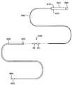
- FIG. 4Ashows a side view of one variation for a tissue engaging helix.
- FIG. 4Bshows a side view of another variation for a helix having a reduced pitch.
- FIG. 4Cshows a side view of another variation for a helix having a varied pitch.
- FIG. 4Dshows a side view of another variation for a helix having a piercing needle positioned through the helix.
- FIG. 4Eshows a side view of another variation having a dual helix.
- FIG. 4Fshows a side view of another variation for a helix having a decreasing diameter.
- FIG. 4Gshows a side view of another variation for a helix combined with a grasper.
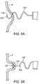
- FIGS. 5A and 5Bshow a hollow helix variation for deploying anchors directly through the helix.
- FIGS. 6A and 6Bshow another variation of a helix with a protective sheath which may be advanced over the helix.
- FIGS. 7A and 7Bshow another variation of a helix with an atraumatic member which may be advanced longitudinally through the helix.
- FIG. 8shows another variation of a helix with a blunted member which may be advanced longitudinally through the helix.
- FIGS. 9A and 9Bshow a helix which may be energized to reform into a straightened configuration, respectively, to facilitate its withdrawal from tissue.
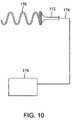
- FIG. 10shows a helix variation which may be energized by a power source for use in ablating surrounding tissue.
- FIGS. 11A and 11Bshow side views of one variation of the tissue manipulation assembly having cam-actuated extension members.
- FIGS. 11C and 11Dshow detail views of the cam-actuation for the assembly of FIGS. 11A and 11B .
- FIGS. 12A and 12Bshow side views of another variation of extension members which are biased towards one another.
- FIGS. 13A and 13Bshow side views of another variation of extension members which are actuated via a linkage assembly.
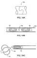
- FIGS. 14A to 14Cshow side views of another variation of extension members which are actuatable via one or more hinged arms interconnecting the extension members.
- FIGS. 15A and 15Bshow side views of another variation where one or more extension members are biased away from one another.
- FIGS. 16A and 16Bshow side views of another variation where one or more extension members are configured to be passively biased.
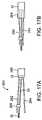
- FIGS. 17A and 17Bshow side views of another variation of extension members which are actuatable via a translatable sleeve.
- FIG. 18shows a side view of a tissue manipulation assembly with a lower extension member having a longer length than the upper extension member.
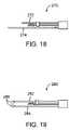
- FIG. 19shows a side view of another variation where one or both extension members may have tips atraumatic to tissue.
- FIGS. 20A and 20Bviews of a variation of lower extension members which may be configured to be actuatable.
- FIG. 20Cshow a top view of a lower extension member which may be configured into “C” shape.
- FIGS. 21A and 21Bshow perspective and top views of a lower extension member having one or more energize-able wires disposed thereon for tissue ablation.
- FIG. 22Ais a detail side view of an ablative tissue manipulation assembly advanced through a shape-lockable overtube and positioned adjacent to a tissue wall.
- FIG. 22Bis a detail side view a assembly shown in FIG. 22A forming a tissue fold.
- FIG. 22Cis a detail side view of additional tissue folds prepared to be approximated together.
- FIG. 22Dis detail side view of the tissue folds shown in FIG. 22C now approximated together.
- FIG. 22Eis a detail side view of the approximated tissue folds shown in FIG. 22D now fused together.
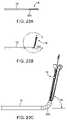
- FIGS. 23A to 23Cshow side views of a tissue manipulation assembly which may be configured to articulate into an angle relative to the tubular body.
- FIGS. 24A and 24Bshow side and perspective detail views, respectively, of a launch tube specially configured to flex in specified planes.
- FIGS. 24C and 24Dshow side views of a portion of the launch tube having one or more coatings or coverings.
- FIG. 25shows an illustrative side view of the angle formed between the deployed needle assembly and a longitudinal axis of the tissue manipulation assembly.
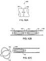
- FIG. 26Ashows a partial side view of a launch tube variation having an extended launch tube distal portion for aligning the needle body for deployment.
- FIGS. 26B and 26Cshow cross-sectional views of the needle body and launch tube distal portion having various keyed cross-sectional areas.
- FIG. 27Ashows another cross-sectional view where the needle body may be keyed to the launch tube.
- FIG. 27Bshows a side view of the keyed needle body of FIG. 27A .
- FIG. 28shows a partial side view of an over-driven launch tube.
- FIGS. 29A and 29Bshow partial side views of an assembly having curved deployable needle assemblies.
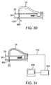
- FIG. 30shows a variation where the needle body may be curved via an anvil.
- FIG. 31shows another variation in which an optical fiber or an optical fiber configured as a needle body may be advanced through a launch tube to provide visualization.
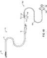
- FIG. 32shows a variation of the needle body which may be ultrasonically actuated.
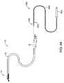
- FIG. 33shows a torqueable variation of the needle body.
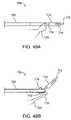
- FIGS. 34A and 34Bshow needle body variations which may be configured to deploy tissue anchors via a side opening.
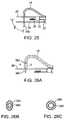
- FIGS. 35A to 35Cshow end views of a tissue manipulation assembly which may incorporate various colors into the device to facilitate orientation.
- FIGS. 36A to 36Cshow the corresponding top views, respectively, of the device of FIGS. 35A to 35C .
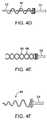
- FIGS. 37A to 37Dshow side views of various needle bodies which may be colored, have visual markers thereon, dimpled, or have radio-opaque coatings respectively.
- FIGS. 38A to 38Cshow partial side views of variations of a handle for controlling and articulating the tissue manipulation assembly.
- FIGS. 39A to 39Cshow top, side, and cross-sectional views, respectively, of another variation of a handle having a multi-position locking and needle assembly advancement system.
- FIG. 39Dshows an assembly view of the handle of FIG. 39A connected to the tissue manipulation assembly via a rigid or flexible tubular body or shaft.
- FIGS. 40A and 40Bshow perspective and cross-sectional views, respectively, of another variation of a handle having a reversible configuration.
- FIGS. 41A and 41Bshow partial cross-sectional side and detail views, respectively, of another variation of a handle having a pivotable articulation control.
- FIG. 42Ashows a side view of the handle of FIG. 41A having the multi-position locking and needle assembly advancement system.
- FIGS. 42B to 42Dshow end views of the handle of FIG. 42A and the various positions of the multi-position locking and needle assembly advancement system.
- FIG. 43Ashows a perspective view of one variation of the multi-position locking and needle assembly advancement system.
- FIGS. 43B to 43Eshow illustrative side views of the system of FIG. 43A configured in various locking and advancement positions.
- FIG. 44illustrates a side view of a needle deployment assembly which may be loaded or advanced into an approximation assembly.
- FIG. 45Ashows a side view of one variation of a needle deployment assembly.
- FIG. 45Bshows an exploded assembly of FIG. 45A in which the tubular sheath is removed to reveal the anchor assembly and elongate pusher element.
- FIGS. 46A and 46Bshow partial cross-sectional side views of a shuttle element advanced within the needle assembly housing.
- FIGS. 47A and 47Billustrate one variation of deploying the anchors using the needle assembly.
- FIG. 47Cillustrates a partial cross-sectional view of one variation of the needle and anchor assemblies positioned within the launch tube.
- FIG. 48shows a side view of another variation in which a manipulatable grasping needle assembly may be loaded into the approximation assembly.
- FIGS. 49A and 49Bshow detail side views of a variation of the manipulatable grasping needle of FIG. 48 .
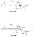
- FIGS. 50A and 50Bshow detail side views of another variation of the manipulatable grasping needle which may be utilized to deploy anchors.
- FIGS. 51A and 51Bshow partial cross-sectional views of various methods for aligning a suture through the anchor assembly within the needle assembly.
- FIG. 51Cshows a partial cross-sectional view of an anchor assembly variation utilizing a spacer between adjacent anchors within the needle assembly.
- FIGS. 52A and 52Bshow perspective detail views of unexpanded anchors having interlocking features on one or more of the collars for temporarily interlocking the anchors and/or elongate pusher to one another.
- FIG. 52Cshows a detail perspective view of a curved interlocking feature which may be integrated on the distal end of the elongate pusher.
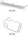
- FIGS. 53A and 53Bshow another variation of an interlocking feature which may be integrated into one or more anchors.
- FIGS. 54A to 54Cshow a curved-tab locking feature variation which may be utilized in deploying one or more anchors.
- FIGS. 55A to 55Cshow an interlocking feature variation which may be utilized in deploying one or more anchors.
- FIGS. 56A to 56Cshow a tabbed locking feature variation which may be utilized in deploying one or more anchors.
- FIGS. 57A to 57Cshow a pin and groove locking feature variation which may be utilized in deploying one or more anchors.
- FIGS. 58A to 58Cshow a rotational coil locking feature variation which may be utilized in deploying one or more anchors.
- FIGS. 59A to 59Cshow an electrolytic joint locking feature variation which may be utilized in deploying one or more anchors.
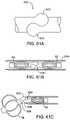
- FIGS. 60A to 60Cshow a ball-groove locking feature variation which may be utilized in deploying one or more anchors.
- FIGS. 61A to 61Cshow a balled-joint locking feature variation which may be utilized in deploying one or more anchors.
- FIGS. 62A to 62Cshow a magnetic locking feature variation which may be utilized in deploying one or more anchors.
- FIG. 63shows a locking feature variation utilizing a cross-member.
- FIGS. 64A to 64Cshow various additional feature for controlling the deployment of anchors.
- FIG. 65shows a variation for deploying multiple anchors adjacently aligned within a single needle assembly.
- FIGS. 66A to 66Cshow partial cross-sectional side, bottom, and end views, respectively, of another variation for deploying multiple anchors in a controlled manner via corresponding retaining tabs.
- a tissue plication tool having a distal tipmay be advanced (transorally, transgastrically, etc.) into the stomach.
- the tissuemay be engaged or grasped and the engaged tissue may be moved to a proximal position relative to the tip of the device, thereby providing a substantially uniform plication of predetermined size. Examples of creating and forming tissue plications may be seen in further detail in U.S. patent application Ser. No. 10/735,030 filed Dec. 12, 2003, which is incorporated herein by reference in its entirety.
- the anchoring and securement devicesmay be delivered and positioned via an endoscopic apparatus that engages a tissue wall of the gastrointestinal lumen, creates one or more tissue folds, and disposes one or more of the anchors through the tissue fold(s).
- the tissue anchor(s)may be disposed through the muscularis and/or serosa layers of the gastrointestinal lumen.
- a distal tip of a tissue plication apparatusmay engage or grasp the tissue and move the engaged tissue to a proximal position relative to the tip of the device, thereby providing a substantially uniform plication of predetermined size.
- Formation of a tissue foldmay be accomplished using at least two tissue contact areas that are separated by a linear or curvilinear distance, wherein the separation distance between the tissue contact points affects the length and/or depth of the fold.
- a tissue grabbing assemblyengages or grasps the tissue wall in its normal state (i.e., non-folded and substantially flat), thus providing a first tissue contact area.
- the first tissue contact areathen is moved to a position proximal of a second tissue contact area to form the tissue fold.
- the tissue anchor assemblythen may be extended across the tissue fold at the second tissue contact area.
- a third tissue contact pointmay be established such that, upon formation of the tissue fold, the second and third tissue contact areas are disposed on opposing sides of the tissue fold, thereby providing backside stabilization during extension of the anchor assembly across the tissue fold from the second tissue contact area.
- the first tissue contact areamay be utilized to engage and then stretch or rotate the tissue wall over the second tissue contact area to form the tissue fold.
- the tissue foldmay then be articulated to a position where a portion of the tissue fold overlies the second tissue contact area at an orientation that is substantially normal to the tissue fold.
- a tissue anchormay then be delivered across the tissue fold at or near the second tissue contact area.
- the plication assembly 10generally comprises a catheter or tubular body 12 which may be configured to be sufficiently flexible for advancement into a body lumen, e.g., transorally, percutaneously, laparoscopically, etc.
- Tubular body 12may be configured to be torqueable through various methods, e.g., utilizing a braided tubular construction, such that when handle 16 is manipulated and rotated by a practitioner from outside the body, the torquing force is transmitted along body 12 such that the distal end of body 12 is rotated in a corresponding manner.
- Tissue manipulation assembly 14is located at the distal end of tubular body 12 and is generally used to contact and form the tissue plication, as mentioned above.
- FIG. 1Bshows an illustrative detail side view
- FIG. 1Cshows a perspective view of tissue manipulation assembly 14 which shows launch tube 18 extending from the distal end of body 12 and in-between the arms of upper extension member or bail 20 .
- Launch tube 18may define launch tube opening 24 and may be pivotally connected near or at its distal end via hinge or pivot 22 to the distal end of upper bail 20 .
- Lower extension member or bail 26may similarly extend from the distal end of body 12 in a longitudinal direction substantially parallel to upper bail 20 .
- Upper bail 20 and lower bail 26need not be completely parallel so long as an open space between upper bail 20 and lower bail 26 is sufficiently large enough to accommodate the drawing of several layers of tissue between the two members.
- Tissue acquisition member 28may be an elongate member, e.g., a wire, hypotube, etc., which terminates at a tissue grasper or engager 30 , in this example a helically-shaped member, configured to be reversibly rotatable for advancement into the tissue for the purpose of grasping or acquiring a region of tissue to be formed into a plication.
- Tissue acquisition member 28may extend distally from handle 16 through body 12 and distally between upper bail 20 and lower bail 26 .
- Acquisition member 28may also be translatable and rotatable within body 12 such that tissue engager 30 is able to translate longitudinally between upper bail 20 and lower bail 26 .
- an optional guide or linear bearing 32may be connected to upper 20 or lower bail 26 to freely slide thereon.
- Guide 32may also be slidably connected to acquisition member 28 such that the longitudinal motion of acquisition member 28 is supported by guide 32 .
- Tissue manipulation assembly 14may be advanced into a body lumen such as the stomach and positioned adjacent to a region of tissue wall 40 to be plicated.
- launch tube 18may be configured in a delivery profile such that tube 18 is disposed within or between the arms of upper bail 20 to present a relatively small profile.
- tissue grasper or engager 30may be advanced distally such that tissue grasper or engager 30 comes into contact with tissue wall 40 at acquisition location or point 42 .
- guide 32if utilized, may slide distally along with tissue grasper or engager 30 to aid in stabilizing the grasper.
- a helically-shaped tissue grasper or engager 30is utilized, as illustrated in FIG. 2B , it may be rotated from its proximal end at handle 16 and advanced distally until the tissue at point 42 has been firmly engaged by tissue grasper or engager 30 . This may require advancement of tissue grasper or engager 30 through the mucosal layer and at least into or through the underlying muscularis layer and possibly into or through the serosa layer.
- tissue grasper or engager 30may then be pulled proximally between upper 20 and lower bails 26 via tissue grasper or engager 30 such that the acquired tissue is drawn into a tissue fold 44 , as seen in FIG. 2C .
- guide 32may also slide proximally to aid in stabilizing the device especially when drawing the tissue fold 44 .
- launch tube 18may be advanced from its proximal end at handle 16 such that a portion 46 of launch tube 18 , which extends distally from body 12 , is forced to rotate at hinge or pivot 22 and reconfigure itself such portion 46 forms a curved or arcuate shape that positions launch tube opening 24 perpendicularly relative to a longitudinal axis of body 12 and/or bail members 20 , 26 .
- Launch tube 18 , or at least portion 46 of launch tube 18is preferably fabricated from a highly flexible material or it may be fabricated, e.g., from Nitinol tubing material which is adapted to flex, e.g., via circumferential slots, to permit bending.
- assembly 14may be configured such that launch tube 18 is reconfigured simultaneously with the proximal withdrawal of tissue grasper or engager 30 and acquired tissue 44 .
- the tissue wall of a body lumentypically comprises an inner mucosal layer, connective tissue, the muscularis layer and the serosa layer.
- the staples or anchors used to achieve reduction of the body lumenare preferably engaged at least through or at the muscularis tissue layer, and more preferably, the serosa layer.
- stretching of tissue fold 44 between bail members 20 , 26permits an anchor to be ejected through both the muscularis and serosa layers, thus enabling durable gastrointestinal tissue approximation.
- needle assembly 48may be advanced through launch tube 18 via manipulation from its proximal end at handle 16 to pierce preferably through a dual serosa layer through tissue fold 44 .
- Needle assembly 48is preferably a hollow tubular needle through which one or several tissue anchors may be delivered through and ejected from in securing the tissue fold 44 , as further described below.
- tissue fold Fmay comprise a plication of tissue created using the apparatus described herein or any other tool configured to create such a tissue plication.
- Tissue fold Fmay be disposed within a gastrointestinal lumen, such as the stomach, where tissue wall W may define the outer or serosal layer of the stomach.
- Anchor delivery assemblymay generally comprise launch tube 18 and needle assembly 48 slidingly disposed within launch tube lumen 52 .
- Needle assembly 48is generally comprised of needle 54 , which is preferably a hollow needle having a tapered or sharpened distal end to facilitate its travel into and/or through the tissue.
- Other parts of the assemblysuch as upper and lower bail members 20 , 26 , respectively, and tissue acquisition member 28 have been omitted from these figures only for clarity.
- needle 54may be urged or pushed into or through tissue fold F via delivery push tube or catheter 64 from its proximal end preferably located within handle 16 .
- Delivery push tube or catheter 64may comprise an elongate flexible tubular member to which needle 54 is connected or attached via joint 62 .
- needle 54 and delivery push tube 64may be integrally formed from a singular tubular member.
- Needle 54may define needle lumen 56 through which basket anchor assembly 66 , i.e., distal anchor 58 and/or proximal anchor 60 may be situated during deployment and positioning of the assembly.
- a single suture or flexible element 76may connect proximal anchor 60 and distal anchor 58 to one another.
- element 76may comprise various materials such as monofilament, multifilament, or any other conventional suture material, elastic or elastomeric materials, e.g., rubber, etc.
- suturesmay be made from metals such as Nitinol, stainless steels, Titanium, etc., provided that they are formed suitably thin and flexible.
- metallic sutures with the anchoring mechanisms described hereinmay additionally provide several benefits. For example, use of metallic suture material may decrease any possibilities of suture failure due to inadvertent cutting or shearing of the suture, it may provide a suture better able to withstand the acidic and basic environment of the gastrointestinal system, and it may also enhance imaging of the suture and anchor assembly if examined under conventional imaging systems such as X-rays, fluoroscopes, MRI, etc. As used herein, suture 76 may encompass any of these materials or any other suitable material which is also biocompatible.
- Needle 54may optionally define a needle slot along its length to allow suture 76 to pass freely within and out of needle 54 when distal anchor 58 is ejected from needle lumen 56 .
- needle 54may define a solid structure with suture 76 being passed into and through needle lumen 56 via the distal opening of needle 54 .
- the proximal end of suture 76may pass slidingly through proximal anchor 60 to terminate in a suture loop.
- the proximal end of suture 76may terminate proximally of the apparatus 10 within control handle 16 , proximally of control handle 16 , or at some point distally of control handle 16 .
- a suture loopmay be provided to allow for a grasping or hooking tool to temporarily hold the suture loop for facilitating the cinching of proximal 60 and distal 58 anchors towards one another for retaining a configuration of tissue fold F, as described in further detail in U.S. patent application Ser. No. 10/840,950, which has been incorporated by reference above.
- anchor pushrod or member 78may be actuated also via its proximal end to eject distal anchor 58 .
- needle 54may be retracted back through tissue fold F by either retracting needle 54 back within launch tube lumen 18 or by withdrawing the entire anchor delivery assembly 50 proximally relative to tissue fold F.
- proximal anchor 60may then be ejected from launch tube 18 on a proximal side of tissue fold F. With both anchors 58 , 60 disposed externally of launch tube 18 and suture 76 connecting the two, proximal anchor 60 may be urged into contact against tissue fold F, as shown in FIG. 3B . As proximal anchor 60 is urged against tissue fold F, proximal anchor 60 or a portion of suture 76 may be configured to provide any number of directionally translatable locking mechanisms which provide for movement of an anchor along suture 76 in a first direction and preferably locks, inhibits, or prevents the reverse movement of the anchor back along suture 76 . In other alternatives, the anchors may simply be delivered through various elongate hollow tubular members, e.g., a catheter, trocars, etc.
- the basket anchorsmay comprise various configurations suitable for implantation within a body lumen. Basket anchors are preferably reconfigurable from a low profile delivery configuration to a radially expanded deployment configuration in which a number of struts, arms, or mesh elements may radially extend once released from launch tube 18 or needle 54 . Materials having shape memory or superelastic characteristics or which are biased to reconfigure when unconstrained are preferably used, e.g., spring stainless steels, Ni—Ti alloys such as Nitinol, etc. In FIGS.
- each of the basket anchor 58 , 60is illustrated as having a number of reconfigurable struts or arm members 72 extending between distal collar 68 and proximal collar 70 ; however, this is intended only to be illustrative and suitable basket anchors are not intended to be limited to baskets only having struts or arms. Examples of suitable anchors are further described in detail in U.S. patent application Ser. No. 10/612,170, which has already been incorporated herein above.
- FIG. 3Bshows distal basket anchor 58 delivered through tissue fold F via needle 54 and launch tube 18 .
- the other parts of the plication assemblysuch as upper and lower bail members 20 , 26 , respectively, and tissue acquisition member 28 have been omitted from these figures only for clarity.
- FIG. 3Bshows one variation where a single fold F may be secured between proximal anchor 60 and distal anchor 58 ′.
- basket anchor 58 ′has been urged or ejected from needle 54 and is shown in its radially expanded profile for placement against the tissue surface.
- a terminal end of suture 76may be anchored within the distal collar of anchor 58 ′ and routed through tissue fold F and through, or at least partially through, proximal anchor 60 , where suture 76 may be cinched or locked proximally of, within, or at proximal anchor 60 via any number of cinching mechanisms.
- Proximal anchor 60is also shown in a radially expanded profile contacting tissue fold F along tissue contact region 74 . Locking or cinching of suture 76 proximally of proximal anchor 60 enables the adequate securement of tissue fold F.
- distal basket anchor 58may be disposed distally of at least one additional tissue fold F′, as shown in FIG. 3B , while proximal anchor 60 may be disposed proximally of tissue fold F.
- suture 76may be similarly affixed within distal anchor 58 and routed through proximal anchor 60 , where suture 76 may be cinched or locked via proximal anchor 60 , as necessary. If tissue folds F and F′ are to be positioned into apposition with one another, distal basket anchor 58 and proximal anchor 60 may be approximated towards one another.
- proximal anchor 60is preferably configured to allow suture 76 to pass freely therethrough during the anchor approximation. However, proximal anchor 60 is also preferably configured to prevent or inhibit the reverse translation of suture 76 through proximal anchor 60 by enabling uni-directional travel of anchor 60 over suture 76 . This cinching feature thereby allows for the automated locking of anchors 58 , 60 relative to one another during anchor approximation.
- the types of anchors shown and describedare intended to be illustrative and are not limited to the variations shown.
- tissue anchor variationsare shown as “T”-type anchors while other variations are shown as reconfigurable “basket”-type anchors, which may generally comprise a number of configurable struts or legs extending between at least two collars or support members.
- Other variations of these or other types of anchorsare also contemplated for use in an anchor assembly.
- a single type of anchormay be used exclusively in an anchor assembly; alternatively, a combination of different anchor types may be used in an anchor assembly.
- the different types of cinching or locking mechanismsare not intended to be limited to any of the particular variations shown and described but may be utilized in any of the combinations or varying types of anchors as practicable.
- tissue acquisition member 28may be an elongate member, e.g., a wire, hypotube, etc., which has a tissue grasper or engager 30 attached or integrally formed at its distal end for grasping or engaging the tissue.
- the tissue graspermay be formed as a helix having a uniform outer diameter with a constant pitch, as shown in the detail view of helix 80 in FIG. 4A .
- Helix 80may be attached to acquisition member 28 via any suitable fastening method, e.g., adhesives, solder, etc.
- helix 80may be integrally formed from the distal portion of acquisition member 28 by winding or coiling the distal portion in a helix configuration.
- the tissue graspermay be formed into a helix 82 having a pitch which is greater relatively than helix 80 such that the variation of helix 82 has relatively fewer windings, as shown in FIG. 4B .
- a multi-pitch helix 84may be formed having one or more regions with varying pitch along a length of helix 84 .
- multi-pitch helix 84may have a distal portion 86 having a relatively lower pitch and a proximal portion having a relatively higher pitch 88 .
- a single helix having regions of varied pitchmay be utilized to initially pierce and grasp tissue onto the region of lower pitch 86 ; when the helix 84 is rotated to advance into or through the tissue, the pierced tissue advanced over helix 84 may be wound upon the region of higher pitch 88 where the tissue may be better adhered to helix 84 by the tighter windings.
- FIG. 4DAnother variation of a tissue grasper may be seen in FIG. 4D .
- helix 90may have a piercing needle 92 extending through the center and protruding distally of helix 90 to facilitate piercing of the tissue and initial entry of helix 90 into the tissue.
- FIG. 4EYet another variation is shown in FIG. 4E where a dual-helix variation may be utilized.
- first helix 94may be inter-wound with second helix 96 in a dual helix configuration.
- FIG. 4FAnother variation is shown in FIG. 4F in which helix 98 may define a helix having a decreasing diameter distally of acquisition member 28 .
- helix 98may define a helix having a decreasing diameter distally of acquisition member 28 .
- certain aspects of one helix variationmay be utilized in any number of combinations with any of the other aspects of other variations as practicable.
- the variation of the dual-helix in FIG. 4Emay also comprise the piercing needle 92 of FIG. 4D .
- This variationmay also include aspects of the helix 84 having varying regions of differing pitch, as shown in FIG. 4C , and so on in any number of combinations as practicable.
- FIG. 4Gshows yet another variation in dual grasping assembly 100 where helix 102 may utilize articulatable grasping jaw members 104 , 106 in combination with the helix 102 .
- acquisition member 28may be withdrawn proximally to pull the tissue between jaws 104 , 106 , which may then be articulated to further clamp onto the tissue to ensure tissue retention by assembly 100 .
- Articulatable jaws 104 , 106may optionally define serrations or teeth 108 , 110 upon one or more of the jaw members 104 , 106 in contact against the tissue to further facilitate tissue retention.
- FIGS. 5A and 5Bshow side views of a helix variation 120 which may be completely or partially hollow for engaging tissue.
- One or more deployable anchors 124may be positioned within or advanced through hollow helix 120 . With at least the distal portion or tip of hollow helix 120 pierced into or through the tissue T, as shown in FIG. 5A , tissue anchor 124 may be urged from opening 122 defined in hollow helix 120 through any number of methods, e.g., an elongate pusher.
- tissue anchor 124Once tissue anchor 124 has been deployed or ejected from distal opening 122 , helix 120 may be withdrawn proximally partially or entirely from tissue T while leaving anchor 124 behind.
- Anchor 124may be connected to suture 126 which may be routed through or connected to helix 120 such that creation of a tissue fold from tissue T may be achieved by pulling anchor 124 proximally, as shown in FIG. 5B .
- suture 126may be released from helix 120 so that helix 120 may be withdrawn from the region.
- sheath 132may completely or partially cover helix 80 to present an atraumatic surface to the surrounding tissue when the helix 80 is not in use within the patient's body, as shown in FIG. 6B . Additionally, sheath 132 may also be utilized outside the patient to protect helix 80 when handled for transport or during preparation of the device for use. Sheath 132 may be optionally advanced distally over helix 80 or helix 80 may be withdrawn proximally into sheath 132 .
- helix assembly 140may have an insertion member 142 which defines an atraumatic distal end 144 advanced through the center of helix 80 .
- insertion member 142may be advanced distally within helix 80 to the distal end of helix 80 such that inadvertent tissue piercing is prevented by member 142 .
- blunted element 150may be advanced through the center of helix 80 via an elongate delivery member 152 .
- member 150may be withdrawn proximally relative to helix 80 in the same manner as helix assembly 140 above.
- reconfigurable helix 160may be configured to have a configuration for facilitating its advancement into tissue or for withdrawing the helix 160 from tissue.
- FIG. 9Ashows reconfigurable helix 160 is seen in its coiled configuration for piercing and adhering tissue thereto.
- Helix 160may be fabricated from a shape memory alloy, such as Nitinol, to have a relaxed configuration of a helix, as shown in FIG. 9A . Once energy is applied, helix 160 may be configured to reconfigure itself into a straightened configuration 160 ′, as shown in FIG. 9B , to facilitate its removal from the tissue.
- Helix 160may be electrically connected via electrically conductive acquisition member 162 and connection or wires 164 to a power source 166 . If helix 160 were advanced into tissue in its coiled configuration, withdrawal of the helix 160 may be quickly effected by applying energy to helix 160 via power source 166 . Alternatively, power may be applied to helix 160 such that its straightened configuration 160 ′ takes shape to facilitate piercing into tissue. Power may then be removed such that helix 160 conforms into its coiled configuration once in the tissue such that the tissue adheres to the helix 160 .
- the length of helix 160may be insulated to shield the surrounding tissue from the applied energy.
- another variation of the tissue grasping membermay be seen in energizable helix 170 in FIG. 10 .
- the entire length or a partial length of helix 170may be uninsulated such that when helix 170 is energized through electrical connection 174 and through electrically conductive acquisition member 172 via power source 176 , the uninsulated portion or portions of energized helix 170 may be utilized to contact and ablate selected regions of tissue. For instance, prior to or after a tissue fold has been formed, helix 170 may be energized to ablate the areas of the tissue which are to be approximated towards one another to facilitate tissue adhesion between selected regions of tissue folds.
- the upper and/or lower extension members or bailsmay also be configured into a variety of embodiments which may be utilized in any number of combinations with any of the helix variations as practicable.
- the upper and lower extension members or bailsmay be maintained rigidly relative to one another, the upper and/or lower extension members may be alternatively configured to articulate from a closed to an open configuration or conversely from an open to a closed configuration for facilitating manipulation or stabilization of tissue drawn between the bail members.
- the obtained tissuemay be proximally withdrawn between the bail members, which may act as stabilizers for the tissue.
- one or both bail membersmay be articulated or urged to open apart from one another to allow the tissue to enter and become positioned between the bail members.
- One or both bail membersmay then be articulated or urged to clamp or squeeze the tissue fold between the bail members to facilitate stabilization of the tissue fold for tissue manipulation and/or anchor deployment and/or any other procedure to be undertaken.
- upper extension member 182 and lower extension member 184 of active extension assembly 180may be configured to have an open or spread configuration relative to one another when guide or linear bearing 186 is positioned distally along upper extension member 182 .
- Linear bearing 186may be configured to slide freely along upper extension member 182 when urged by acquisition member 28 distally or proximally. Rather than having linear bearing 186 slide along upper extension member 182 , it may be configured alternatively to slide along lower extension member 184 .
- tissue grasper 30 and acquisition member 28distally protruding from extension members 182 , 184 , as shown in FIG. 11A , the desired region of tissue may be acquired by rotating tissue grasper 30 into the tissue.
- tissueOnce tissue has been acquired by tissue grasper 30 , the tissue may be pulled between the opened extension members 182 , 184 by proximally withdrawing tissue grasper 30 and linear bearing 186 may be forced proximally over upper extension member 182 , as shown in the detail view of FIG. 11C .
- One or more projections or pistons 188may protrude proximally from linear bearing 186 such that one or more of these projections 188 comes into contact with actuation lever or member 192 , as shown in FIG.
- FIGS. 12A and 12BAnother articulatable extension assembly may be seen in assembly 200 in the side views of FIGS. 12A and 12B .
- upper extension member 202may project distally opposite lower extension member 204 which may be biased to close towards upper extension member 202 .
- linear bearing 206may be urged distally along upper extension member 202 via acquisition member 28 such that lower extension member 204 is forced or wedged away from upper extension member 202 .
- linear bearing 206may be pulled proximally while sliding along lower member 204 and allowing lower member 204 to spring back towards upper member 202 and over any tissue positioned therebetween, as shown in FIG. 12B .
- extension assembly 210Another articulatable extension assembly is shown in the side views of extension assembly 210 of FIGS. 13A and 13B .
- upper extension member 212 and/or lower extension member 214may be connected to linkage assembly 218 located proximally of the extension members 212 , 214 .
- Linkage assembly 218may be manipulated via any number of control mechanisms such as control wires to urge extension members 212 , 214 between open and closed configurations.
- linkage assembly 218may be configured to open or close upon the proximal or distal advancement of linear bearing 216 relative to linkage assembly.
- FIGS. 14A to 14Cshow side views of another variation in extension assembly 220 where upper and lower extension members 222 , 224 are articulatable between open and closed configurations via a pivoting arm or member 234 interconnecting the two.
- a first end of pivoting arm 234may be in a pivoting connection at pivot 228 with linear bearing 226 , which may slide translationally along upper member 222 .
- a second end of pivoting arm 234may also be in a pivoting connection with lower extension member 224 at pivot 230 , which may remain fixed to lower member 224 .
- Acquisition member 28may also be in a third pivoting connection with pivoting arm 234 at pivot 232 , which may also be configured to allow for the linear translation of acquisition member therethrough.
- both upper and lower extension members 222 , 224are in a closed configuration with linear bearing 226 being advanced distally along upper extension member 222 .
- pivoting arm 234may be pivoted about fixed pivot 230 on lower member 224 while upper member 222 is urged into an open configuration as linear bearing 226 is urged proximally over upper member 222 , as shown in FIG. 14B .
- This expanded or open configurationallows for the positioning of large portions of tissue to be drawn between the extension members 222 , 224 for stabilization.
- FIG. 14Cshows tissue grasper 30 as having been further withdrawn and linear bearing 226 urged proximally such that upper member 222 is urged back into a closed configuration relative to lower member 224 .
- the closing of extension members 222 , 224allows for the members to further clamp upon any tissue therebetween for further stabilization of the tissue.
- FIGS. 15A and 15Bshow another alternative in active extension assembly 240 .
- upper extension member 242may be biased to extend away from lower extension member 244 .
- upper extension member 242may remain in an open configuration relative to lower member 244 for receiving tissue therebetween.
- biased upper member 242may be urged into a closed configuration by pivoting the launch tube 18 about pivot 246 , which may be located along upper member 242 . As launch tube 18 is pivoted into an anchor deployment configuration, the pivoting action may urge upper member 242 towards lower member 244 to clamp upon any tissue therebetween.
- FIGS. 16A and 16Bshow yet another alternative in assembly 250 where upper extension member 252 and/or lower extension member 254 may be passively urged into an open configuration.
- lower extension member 254is shown as being flexed from a relaxed configuration in FIG. 16A to a flexed configuration in FIG. 16B .
- any tissue engaged to tissue grasper 30may urge lower extension member 254 from its normal position 258 to its flexed and opened position.
- lower extension member 254 and/or upper extension member 252may be made from a relatively flexible plastic or metallic material, e.g., Nitinol, spring stainless steel, etc.
- tissueis removed from between the extension members 252 , 254 , lower extension member 254 may return to its normal configuration 258 .
- FIGS. 17A and 17Bshow side views of another assembly 260 in which upper and/or lower extension members 262 , 264 may be biased or configured to flex away from one another, as shown in FIG. 17A .
- an outer sleeve 268 slidingly disposed over tubular body 12may be pushed distally such that sleeve 268 is slid over at least a proximal portion of extension members 262 , 264 such that they are urged towards one another into a closed configuration onto tissue which may be present therebetween, as shown in FIG. 17B .
- FIG. 18shows a side view of extension assembly 270 where lower extension member 274 may be extended in length relative to upper extension member 272 .
- the length of lower extension member 274may be varied depending upon the desired result.
- upper extension member 272may be shortened relative to lower extension member 274 .
- the lengthening of lower extension member 274may be utilized to present a more stable platform for tissue approximated between the extension members 262 , 264 .
- extension assembly 280Another alternative for modifying the extension members is seen in the side view of FIG. 19 in extension assembly 280 .
- one or both extension members 282 , 284may be configured to have atraumatic blunted ends 286 which may be further configured to be flexible to allow tissue to slide over the ends.
- atraumatic ends 286may be configured in a variety of ways provided that an atraumatic surface or feature is presented to the tissue.
- the lower extension member of the tissue manipulation assemblymay be varied as well.
- the needle assembly and tissue anchorsare deployed from the launch tube, typically from the upper extension member, it is preferable to have sufficient clearance with respect to the lower extension member so that unhindered deployment is facilitated.
- One method for ensuring unhindered deploymentis via a lower extension member having a split opening defined near or at its distal end, as shown in the perspective view of tissue manipulation assembly 290 in FIG. 20A . Such a split may allow for any deployed anchors or suture an opening through which to be released from assembly 290 .
- articulatable lower extension assembly 292may have one or both jaw members 296 , 298 articulatable via pivots 300 , 302 , respectively, relative to lower extension member 294 such that one or both jaw members 296 , 298 are able to be moved between a closed configuration, as shown in FIG. 20A , and an open configuration, as shown in FIG. 20B .
- This variation in assembly 290may allow for any needle or anchor assemblies to easily clear lower extension member 294 .
- lower extension member 304is shown in the bottom view of FIG. 20C .
- an enclosing jaw member 306may extend from lower extension member 304 such that an opening 308 along either side of extension member 304 is created.
- Such an opening 308may create a “C”-shaped lower extension member 304 which may facilitate needle and anchor deployment from the tissue manipulation assembly.
- tissue manipulation assembly 310may be seen in the illustrative partial perspective view of FIG. 21A .
- one or both extension membersmay be utilized to selectively ablate regions of tissue.
- Assembly 310for instance may have a tissue ablation assembly 312 integrated into the lower extension member 320 .
- tissue ablation assembly 312as seen in the top view of FIG. 21B , may incorporate one or more wires or electrically conductive elements 318 upon lower extension member 320 to create a tissue ablation region.
- the lower extension member 320may be fabricated from a non-conductive material upon which wires 318 may be integrated.
- the entire lower member 320may be electrically conductive with regions selectively insulated leaving non-insulated areas to create ablation regions 318 .
- the wires or regions 318may be electrically connected via wires 314 to power source 316 , which may provide various forms of energy for tissue ablation, e.g., radio-frequency, microwave, etc.
- FIGS. 22A to 22EOne example for use of the ablative tissue manipulation assembly may be seen in FIGS. 22A to 22E where tissue approximation assembly 330 may be seen with tissue manipulation assembly 14 advanced through an optional shape-lockable overtube 332 .
- Ablation region 318is integrated into the lower extension member 320 of the tissue manipulation assembly, as above.
- region 318may, for example, comprise an abrasive surface disposed on lower extension member 320 .
- the lower extension member 320may comprise an ablation electrode for injuring mucosal tissue.
- target mucosal tissue 334contacts lower extension member 320 as well as ablation region 318 . Passive or active actuation of ablation region 318 may then injure and/or remove the target mucosal tissue 334 . As further seen in FIG. 22C , this procedure may be repeated at one or more additional tissue folds 336 , 338 that may then be approximated together, as in FIG. 22D . The contacting injured regions of mucosal tissue promote healing and fusion 340 of the approximated folds, as in FIG. 22E .
- FIG. 23Ashows a distal portion of tubular body 12 and tissue manipulation assembly 14 connected thereto. While tubular body 12 may comprise a rigid or flexible length, tissue manipulation assembly 14 may be further configured to articulate relative to tubular body 12 , as shown in FIG. 23B , to further enhance the maneuverability and manipulation capabilities of tissue manipulation assembly 14 . In one example, assembly 14 may be connected to tubular body 12 via a hinged or segmented articulatable portion 350 , shown in the detail FIG.
- Articulatable portion 350may be configured to allow assembly 14 to become articulated in a single plane or it may also be configured to allow a full range of motion unconstrained to a single plane relative to tubular body 12 . Articulation of assembly 14 may be accomplished any number of various methods, e.g., control wires.
- tissue manipulation assembliesAny of the variations of the tissue manipulation assemblies or aspects of various features of the tissue manipulation assemblies is intended to be utilized in any number of combinations with other aspects of other variations as practicable. Moreover, any of the variations relating to the tissue manipulation assemblies may also be used in any number of combinations, as practicable, with the helix variations described above, if so desired.
- FIG. 24AAn illustrative side view of a partial launch tube 18 configured for anchor deployment may be seen in FIG. 24A .
- Launch tube 18is typically configured to partially translate relative to the tissue manipulation assembly such that a distal portion of the launch tube 18 may be articulated perpendicularly to the tissue to be pierced.
- Launch tube 18may be made from a variety of flexible materials which are flexible yet sufficiently strong to withstand repeated flexing of the tube.
- FIG. 24Bshows a portion 360 of launch tube 18 which may be fabricated from a metal such as Nitinol, stainless steel, titanium, etc. To facilitate the flexure of tube 18 , such a tube may be selectively scored or cut to enhance the directional flexibility of the tube 18 . Accordingly, in one variation, a plurality of circumferential cuts or slits 366 may be made in the portion of launch tube 18 which is flexed. Cuts 366 may extend between one or more lengths or spines 362 , 364 of uncut tube material which may extend over the length of the flexible portion. These spines 362 , 364 in combination with the cuts 366 may facilitate the directional flexibility or bending of launch tube 18 in a singular bending plane. Cuts 366 may be made along the launch tube 18 using any number methods, e.g., mechanical cutting, laser cutting, chemical etching, etc.
- FIGS. 24C and 24DAnother variation of launch tube 18 is shown in the partial views of FIGS. 24C and 24D .
- Launch tube wall 368may be seen in FIG. 24C with an optional inner covering or coating 370 while FIG. 24D shows another variation of launch tube wall 368 with an optional additional outer coating 372 .
- Inner covering or coating 370may be comprised of a lubricious material, e.g., PTFE, etc., to facilitate the ease with which the needle assembly may be advanced or withdrawn through launch tube 18 .
- outer covering or coating 372may also comprise a lubricious material to facilitate the translation of launch tube relative to tubular body 12 . Either or both coatings 370 , 372 may also ensure the structural integrity of launch tube 18 as well.
- launch tube 18In advancing launch tube 18 into a configuration where its distal opening is transverse to the tissue to be pierced, launch tube 18 is preferably advanced until the deployed needle body 380 of the needle assembly emerges from launch tube 18 perpendicularly to the tissue drawn between the extension members, and particularly to upper extension member 20 .
- the distal opening of launch tube 18may be configured to form an angle, ⁇ , relative generally to the tissue manipulation assembly, as shown in FIG. 25 .
- Angle, ⁇is preferably close to 90° but it may range widely depending upon the amount of tissue grasped as well as the angle desired; thus, the launch tube 18 may be configured to translate over a specified distance via detents or locks to ensure the formed angle.
- a distal portion of launch tube 18may be modified to include an extended portion 382 which is configured to remain straight even when launch tube 18 is flexed into its deployment configuration, as shown in FIG. 26A .
- Extended portion 382may comprises an uncut portion of launch tube 18 or it may alternatively comprise a strengthened region of the launch tube 18 . In either case, the extended portion 382 may provide additional columnar support to needle body 380 during needle deployment from launch tube 18 to help ensure the linear deployment of the needle body 380 into or through the tissue.
- FIGS. 26B and 26Cshow the needle body 380 positioned within the distal portion 382 of launch tube 18 .
- needle body 380may define a cross-sectional shape, other than circular, which is keyed to the extended distal portion 382 of launch tube 18 .
- needle body 380may define an elliptical cross-sectional shape within a complementary elliptically-shaped distal portion 384 , as seen in FIG. 26B .
- needle body 380may be configured into a polygonal shape, e.g., octagonal, within an octagonally-shaped distal portion 386 , as seen in FIG. 26C .
- a polygonal shapee.g., octagonal
- Any number of other cross-sectional shapesmay be employed, e.g., rectangles, hexagons, heptagons, octagons, etc.
- needle body 390may instead be keyed to launch tube 394 to ensure a specified deployment trajectory of needle body 390 from keyed launch tube 394 , as shown in the cross-sectional view of FIG. 27A .
- keyingmay include attaching or forming a key or projection 392 , e.g., a length of wire, along one or more sides of needle body 390 , as shown in the side view of needle body 390 and delivery catheter 398 .
- Launch tube 394may define a groove or channel 396 along an inner surface through which the key 392 on needle body 390 may travel within while maintaining an orientation of needle body 390 relative to launch tube 394 .
- FIG. 28Yet another variation for ensuring needle trajectory from the launch tube may be seen in the partial cross-sectional view of FIG. 28 .
- Various features of the tissue manipulation assemblyhave been omitted merely for clarity.
- launch tube 400may be overdriven relative to the tissue manipulation assembly and upper extension member 20 , i.e., the angle, ⁇ , formed between the deployed needle body 402 and upper extension member 20 is greater than 90°.
- the launch tube 400 and deployed needle body 402may be overdriven to ensure that the trajectory of needle body 402 is directed towards the assembly rather than away from the assembly.
- any of the launch tube variations described hereinis not intended to be limited to the examples described but is intended to be utilized in any number of combinations with other aspects of other variations as practicable. Moreover, any of the variations relating to the launch tube variations may also be used in any number of combinations, as practicable, with variations of other features as described above, if so desired.
- the launch tube needleis preferably a hollow tapered needle body which is configured to pierce into and through tissue.
- the needle bodymay have a variety of tapered piercing ends to facilitate its entry into tissue.
- FIG. 29Ashows curved or curvable needle body 410 deployed from launch tube 18 .
- needle body 410may be constrained into a straightened configuration when positioned within launch tube 18 .
- needle body 410may be adapted to reconfigure itself into a curved configuration directed towards the tissue manipulation assembly.
- curved needle body 410may be made from a super elastic alloy or shape memory alloy such as Nitinol.
- FIG. 29Bshows another variation in which curved needle body 410 may be launched from an under-deployed launch tube 412 .
- needle body 420may be curved via an anvil 422 configured to receive and deflect the travel of needle body 420 into a curved needle body.
- Needle body 420may be comprised of a super elastic alloy such as Nitinol.
- Anvil 422may be mounted on either lower extension member 26 , as shown in the figure, or upper extension member 20 , depending upon the desired results.
- the needle bodymay be replaced with a fiber optic needle 430 .
- a needle 430may be deployed through the launch tube 18 to provide visualization of the tissue region prior to, during, or after anchor deployment.
- fiber optic needle 430may be advanced directly into or through the tissue region for visualization of the tissue.
- fiber optic needle 430may be in communication via fiber optic wire or wires 432 to a processor 434 and an optional monitor 436 for viewing the tissue region from outside the patient's body.
- an ultrasonic vibrating needle body 440may be electrically connected via wires 442 to power source 444 for driving the needle body, e.g., using a piezoelectric transducer to supply the vibratory motion.
- FIG. 33illustrates yet another alternative where rather than utilizing a vibrating needle body, a torqueable needle body 450 , which may be torqued about its proximal end, may be utilized to facilitate entry into the tissue.
- the torqueable needle body 450may be connected via a catheter length having high-torque characteristics, e.g., via braiding along the catheter shaft.
- needle body 450may further define threading 452 over its outer surface to facilitate entry of the needle body 450 into the tissue.
- the direction of torquemay simply be reversed while pulling proximally on needle body 450 .
- tissue anchormay alternatively be deployed through one or more side openings defined proximally of the distal tip of the needle body.
- tissue anchor 60may be deployed from needle body 460 through side opening 462 .
- a ramp or taper 464may be defined within needle body 460 leading to side opening 462 to facilitate the ejection of the tissue anchors from needle body 460 .
- FIG. 34Bshows another alternative needle body 466 having a side opening 462 .
- Needle knife 468may be utilized to facilitate the initial entry into the tissue while tapered needle body 466 may be used to dilate the opening created by needle knife 468 and facilitate the entry of needle body 466 into and/or through the tissue.
- FIGS. 35A to 36CAnother variation on the needle body and launch tube is shown in FIGS. 35A to 36C .
- FIG. 35Ashows an end view looking directly along tubular body 12 towards the tissue manipulation assembly with the launch tube 470 flexed into its deployment configuration.
- FIGS. 35B and 35Cshow the end view of FIG. 35A where the assembly is angled relatively to the left and to the right, respectively.
- the terms “left” and “right”are intended to refer only to the orientation of the assembly as shown in the figures and are used for illustrative purposes.
- FIG. 36Ashows a top view of the assembly corresponding to FIG. 35A while FIGS. 36B and 36C also show top views corresponding to FIGS. 35B and 35C , respectively.
- portions of the assemblysuch as launch tube 470 or the needle assembly, may be coated or covered with a color, e.g., red, orange, yellow, green, blue, indigo, violet, silver, black, or combinations thereof.
- the aid of coloring portions of the assemblymay help with gaining orientation of the device.
- FIG. 37Ashows a needle body 480 which may be colored with any of the colors described above to facilitate orientation of the needle body 480 when deployed from the launch tube.
- needle body 482may have gradations or indicators 484 along its surface, as shown in FIG. 37B , to provide a visual indication to the surgeon or physician of the position of needle body 482 when advanced into or through the tissue or when deployed from the launch tube.
- Each of the gradations 484may be separated by a uniform distance or various positions along the needle body 482 may be marked to indicate specified locations.
- FIG. 37Cshows yet another variation in which the outer surface of needle body 486 may be dimpled 488 .
- the presence of dimples 488may be used to enhance the visualization of needle body 486 within the patient body.
- dimples 488may also enhance the visualization of needle body 486 under ultrasound imaging, if utilized, either for imaging the position of needle body 486 or for locating needle body 486 within the patient's body if the needle body 486 were to inadvertently break off.
- needle body 490may be coated or covered with a radio-opaque material 492 to further enhance visualization of the needle body 490 , for example, if x-ray or fluoroscopic imaging were utilized.
- the radio-opaque coating 492e.g., platinum, nickel, etc., may also be further coated with a lubricious material to facilitate needle insertion into and/or through the tissue.
- any of the needle body and needle assembly variations described hereinis not intended to be limited to the examples described but is intended to be utilized in any number of combinations with other aspects of other variations as practicable. Moreover, any of the variations relating to the needle body variations may also be used in any number of combinations, as practicable, with variations of other features as described above, if so desired.
- the tissue manipulation assemblymay be manipulated and articulated through various mechanisms.
- One such assembly which integrates each of the functions into a singular unitmay be seen in the handle assembly which is connected via tubular body 12 to the tissue manipulation assembly.
- Such a handle assemblymay be configured to separate from tubular body 12 , thus allowing for reusability of the handle.
- a handlemay be fabricated from a variety of materials such as metals or plastics, provided that the materials are preferably biocompatible. Examples of suitable materials may include stainless steel, PTFE, Delrin®, etc.
- handle enclosure 502may connect with tubular body 12 at its distal end at tubular interface 504 .
- the proximal end of handle 500may define acquisition member opening 506 which opens to acquisition member receiving channel 508 defined through enclosure 502 from opening 506 to tubular interface 504 .
- the acquisition member 28may be routed through receiving channel 508 with the proximal end 510 of acquisition member 28 extending proximally of enclosure 502 for manipulation by the user.
- Acquisition member proximal end 510may further have an acquisition member rotational control 512 that the user may grasp to manipulate acquisition member 28 .
- Acquisition member receiving channel 508preferably has a diameter which is sufficiently large enough to allow for the translational and rotational movement of acquisition member through the receiving channel 508 during tissue manipulation.
- Acquisition member lock 524e.g., a screw or protrusion, may also extend at least partially into acquisition member receiving channel 508 such that lock 524 may be urged selectively against acquisition member 28 to freeze a position of acquisition member 28 , if so desired.
- the terminal end of receiving channel 508may extend to tubular interface 504 such that receiving channel 508 and tubular body 12 are in communication to provide for the passage of acquisition member 28 therethrough.
- the handle enclosure 502may also provide a needle assembly receiving channel 514 through which needle assembly control 516 and needle assembly catheter 518 may be translated through.
- Needle assembly receiving channel 514may extend from needle assembly opening 520 also to tubular interface 504 . Needle assembly receiving channel 514 extends to tubular interface 504 such that needle assembly receiving channel 514 and tubular body 12 are also in communication to provide for the passage of needle assembly catheter 518 therethrough.
- the launch tube 18may be advanced distally and rotated into its deployment configuration.
- the needle assemblymay be advanced into and/or through the tissue by urging needle assembly control 516 and needle assembly catheter 518 distally into needle assembly receiving channel 514 , as shown by the advancement of control 516 in FIG. 38B .
- the tissue anchorsmay then be deployed from the needle assembly catheter 518 via the needle assembly control 516 , as further described below. Withdrawal of the needle assembly from the tissue may be accomplished by the proximal withdrawal of needle assembly control 516 and assembly catheter 518 .
- Tissue manipulation articulation control 522may also be positioned on handle 500 to provide for selective articulation of the tissue manipulation assembly, as shown above in FIGS. 23A to 23C .
- This variationshows articulation control 522 rotatably positioned on handle enclosure 502 such that articulation control 522 may be rotated relative to handle 500 to selectively control the movement of the tissue manipulation assembly.
- Articulation control 522may be operably connected via one or several control wires attached between articulation control 522 and the tissue manipulation assembly. The control wires may be routed through tubular interface 504 and extend through tubular body 12 .
- FIG. 38Cshows another variation of handle enclosure 502 where the tissue manipulation articulation control 526 may be positioned on a side surface of handle enclosure 502 .
- Articulation control 526may include a ratcheting mechanism 528 within enclosure 502 to provide for controlled articulation of the tissue manipulation assembly.
- FIGS. 39A to 39Cshow top, side, and cross-sectional views, respectively, of another variation on the handle assembly.
- an advancement control 530may be adapted to selectively slide translationally and rotationally through a defined advancement channel or groove 532 defined within handle enclosure 502 .
- Advancement control 530may be used to control the deployment and advancement of needle assembly control 516 as well as deployment of the launch tube, as described in further detail below.
- FIG. 39Dshows an assembly side view of the handle assembly, tubular body 12 , and tissue manipulation assembly and the corresponding motion of the assembly when manipulated by the handle.
- tissue acquisition member proximal end 510 and acquisition member control 512may be advanced or withdrawn from the handle enclosure 502 in the direction of arrow 534 to transmit the corresponding translational motion through tubular body 12 to tissue acquisition member 28 and tissue grasper 30 , as indicated by the direction of corresponding arrow 536 .
- acquisition member control 512is rotated relative to handle enclosure 502 , as indicated by rotational arrow 538 , the corresponding rotational motion is transmitted through tubular body 12 to tissue grasper 30 for screwing into or unscrewing from tissue, as indicated by corresponding rotational arrow 540 .
- tubular body 12may be rigid or flexible depending upon the application utilized for the device.
- tissue manipulation assembly articulation control 522may also be seen in this handle variation as being rotatable in the direction of arrow 542 relative to handle enclosure 502 . Depending upon the direction of articulation, control 522 may be manipulated to elicit a corresponding motion from the tissue manipulation assembly about hinge or articulatable section 350 in the direction of arrows 544 .
- FIG. 40AAnother handle variation may be seen in the perspective view of handle assembly 550 , as shown in FIG. 40A .
- This particular variationmay have handle enclosure 552 formed in a tapered configuration which allows for the assembly 550 to be generally symmetrically-shaped about a longitudinal axis extending from its distal end 554 to its proximal end 556 .
- the symmetric feature of handle assembly 550may allow for the handle to be easily manipulated by the user regardless of the orientation of the handle enclosure 552 during a tissue manipulation procedure.
- An additional feature which may further facilitate the ergonomic usability of handle assembly 550may further include at least one opening 558 defined through the enclosure 552 to allow the user to more easily grip and control the handle 550 .
- Another featuremay include grips 560 , 562 which may extend from either side of enclosure 552 .
- acquisition member 564may include additional features to facilitate control of the tissue.
- an additional rotational control 568may extend proximally from control 566 and have a diameter smaller than that of control 566 for controlling fine rotational motion of acquisition member 564 .
- FIG. 40Bshows a side view of the handle assembly 550 of FIG. 40A with the enclosure 552 partially removed for clarity.
- needle assembly control 570may be seen inserted within an additional needle deployment mechanism 576 , as described below in further detail, within needle assembly receiving channel 574 .
- Acquisition member 564may also be seen positioned within acquisition member receiving channel 572 .
- needle deployment mechanism lock 580e.g., a screw or protrusion
- needle deployment mechanism lock 580may be configured to operably extend at least partially into needle assembly receiving channel 574 to selectively lock the launch tube and/or needle assembly control within receiving channel 574 .
- acquisition member receiving channel 582through which the acquisition member may be translated and/or rotated.
- Acquisition member lock 584may also be seen to extend at least partially into the acquisition member receiving channel 582 to selectively lock the acquisition member position, if so desired.
- the acquisition member receiving channel 582may be optionally threaded 586 such that the acquisition member may be advanced or withdrawn using a screw-like mechanism.
- An additional needle deployment mechanism lock 594may also be seen pivotally mounted about pivot 596 within enclosure 522 .
- Mechanism 594may be biased via deployment mechanism biasing element 598 , e.g., a spring, to maintain a biasing force against mechanism 594 such that the needle assembly control may automatically become locked during advancement within enclosure 522 to allow for a more controlled anchor deployment and needle assembly advancement.
- deployment mechanism biasing element 598e.g., a spring
- one or more pivotable tissue manipulation assembly controls 588may be mounted to enclosure 522 and extend from one or both sides of enclosure 522 to provide for articulation control of the tissue manipulation assembly, as described above.
- one or more control wires 592may be connected to control 588 at control wire attachment points 600 .
- Control 588may pivot about tissue acquisition pivot 590 located within handle enclosure 522 .
- the articulation of control wires 592may articulate a position of the tissue manipulation assembly, as discussed above.
- FIG. 41Bshows an example of the range of motion which may be possible for control 588 as it is rotated about pivot 590 .
- FIG. 42Ashows a side view of another variation of handle enclosure 610 which incorporates a needle deployment locking and advancement control 612 which is adapted to be advanced and rotated within needle deployment travel 614 into various positions corresponding to various actions.
- Locking control 612may be utilized in this variation to selectively control access of the needle assembly within handle enclosure 610 as well as deployment of the needle assembly and launch tube advancement with a single mechanism.
- a needle assemblysuch as needle assembly 570 , may be advanced into handle enclosure 610 with locking control 612 initially moved into needle assembly receiving position 616 , shown also in the end view of FIG. 42B .
- the needle assemblymay be locked within enclosure 610 by rotating locking control 612 into its needle assembly locking position 618 , clockwise rotation as shown in the end view of FIG. 42C .
- the needle assemblymay be locked within enclosure 610 to prevent the accidental withdrawal of the needle assembly from the enclosure 610 or inadvertent advancement of the needle assembly into the tissue.
- the needle deployment mechanism within enclosure 610may also be longitudinally translated in a distal direction by urging locking control 612 distally within needle deployment travel 614 .
- Urging locking control 612distally translates not only the needle deployment mechanism within enclosure 610 , but may also translate the launch tube distally such that the launch tube distal portion is pivoted into its deployment configuration, as described above.
- the needle assemblymay also be urged distally with the deployment mechanism such that needle assembly becomes positioned within the launch tube for advancing the needle body into the tissue.
- locking control 612may again be rotated into the needle assembly release position 620 , clockwise rotation as shown in the end view of FIG. 42D .
- the needle assemblymay be free to be translated distally within enclosure 610 for advancing the needle assembly and needle body relative to the launch tube and enclosure 610 .
- the stepsmay be reversed by moving locking control 612 proximally back to its initial needle assembly receiving position 616 so that the needle assembly is unlocked from within enclosure 610 .
- a new needle assemblymay then be introduced into enclosure 610 and the process repeated as many times as desired.
- the locking mechanismmay generally be comprised of outer sleeve 630 disposed about inner sleeve 632 .
- Outer sleeve 630preferably has a diameter which allows for its unhindered rotational and longitudinal movement relative to inner sleeve 632 .
- Needle deployment locking control 612may extend radially from outer sleeve 630 and protrude externally from enclosure 610 , as described above, for manipulation by the user.
- Outer sleeve 630may also define needle assembly travel path 636 along its length.
- Travel path 636may define the path through which needle assembly 570 may traverse in order to be deployed.
- Needle assembly 570may define one or more guides 638 protruding from the surface of assembly 570 which may be configured to traverse within travel path 636 .
- Inner sleeve 634may also define guides 634 protruding from the surface of inner sleeve 634 for traversal within grooves defined in handle enclosure 610 .
- outer sleeve 630is preferably disposed rotatably about inner sleeve 632 such that outer sleeve 630 and inner sleeve 632 are configured to selectively interlock with one another in a corresponding manner when locking control 612 is manipulated into specified positions.
- FIGS. 43B to 43Ethe operation of the locking mechanism of FIG. 43A is described in further detail.
- needle assembly 570may be rotated until guides 638 are able to slide into longitudinal receiving channel 640 of travel path 636 defined in outer sleeve 630 , as shown in FIGS. 43B and 43C .
- Locking control 612may be partially rotated, as described above in FIGS. 42B and 42C , such that outer sleeve is rotated with respect to needle assembly 570 and guides 638 slide through transverse loading channel 642 , as shown in FIG. 43D .
- the locking mechanismmay be advanced distally to deploy the launch tube and to also advance needle assembly 570 distally in preparation for needle assembly 570 deployment.
- locking control 612may again be partially rotated, as shown in FIG. 42D , such that guides 638 on needle assembly 570 are free to then be advanced within longitudinal needle assembly channel 644 relative to the handle enclosure 610 for deploying the needle assembly 570 from the launch tube and into or through the tissue.
- the needle assembly 570may be removed from enclosure 610 and the locking mechanism by reversing the above procedure.
- any of the handle assembly variations described hereinis not intended to be limited to the examples described but is intended to be utilized in any number of combinations with other aspects of other variations as practicable. Moreover, any of the variations relating to the handle assembly variations may also be used in any number of combinations, as practicable, with variations of other features as described above, if so desired.
- needle deployment assembly 650may be deployed through approximation assembly 10 by introducing needle deployment assembly 650 into the handle 16 and through tubular body 12 , as shown in the assembly view of FIG. 44 , such that the needle assembly 656 is advanced from the launch tube and into or through approximated tissue.
- the anchor assembly 658may be deployed or ejected.
- Anchor assembly 658is normally positioned within the distal portion of tubular sheath 654 which extends from needle assembly control or housing 652 .
- the spent needle deployment assembly 650may be removed from approximation assembly 10 , as described above, and another needle deployment assembly may be introduced without having to remove assembly 10 from the patient.
- the length of sheath 654is such that it may be passed entirely through the length of tubular body 12 to enable the deployment of needle assembly 656 into and/or through the tissue.
- FIG. 45Ashows a detailed assembly view of the needle deployment assembly 650 from FIG. 44 .
- elongate and flexible sheath or catheter 654may extend removably from needle assembly control or housing 652 .
- Sheath or catheter 654 and housing 652may be interconnected via interlock 660 which may be adapted to allow for the securement as well as the rapid release of sheath 654 from housing 652 through any number of fastening methods, e.g., threaded connection, press-fit, releasable pin, etc.
- Needle body 662which may be configured into any one of the variations described above, may extend from the distal end of sheath 654 while maintaining communication between the lumen of sheath 654 and needle opening 664 .
- Elongate pusher 666may comprise a flexible wire or hypotube which is translationally disposed within sheath 654 and movably connected within housing 652 .
- a proximally-located actuation member 668may be rotatably or otherwise connected to housing 652 to selectively actuate the translational movement of elongate pusher 666 relative to sheath 654 for deploying the anchors from needle opening 664 .
- Anchor assembly 658may be seen positioned distally of elongate pusher 666 within sheath 654 for deployment from sheath 654 .
- Needle assembly guides 670may also be seen protruding from housing 652 for guidance through the locking mechanism described above.
- FIG. 45Bshows an exploded assembly view of the needle deployment assembly 650 from FIG.
- sheath 654may be disconnected from housing 652 via interlock 660 to reveal the elongate pusher 666 connected to housing 652 and the distal and proximal anchors 58 , 60 , respectively, of anchor assembly 658 .
- FIGS. 46A and 46Bshow partial cross-sectional views of one variation of housing 652 .
- elongate pusher 666may be attached to shuttle 682 , which in turn may be connected to threaded interface element 686 .
- lead screw 684may be rotated about its longitudinal axis to advance threaded interface element 686 over lead screw 684 distally through shuttle channel 680 , as shown in FIG. 46B , where shuttle 682 has been advanced entirely through shuttle channel 680 .
- Tubular sheath interlock 688may be seen at the distal portion of housing 652 through which the elongate pusher 666 may be advanced.
- actuation member 668may be reversed in the opposite direction.
- housing 652may define an indicator window 690 along the length of housing 652 to enable viewing of a visual indicator 692 which may be utilized to indicate the position of the elongate pusher 666 within the sheath 654 .
- indicator 692may move correspondingly within window 690 .
- Positional indicatorsmay also be marked along window 690 to indicate to the user when specified limits have been reached. For instance, positional indicator 694 may be marked such that alignment of indicator 692 with positional indicator 694 is indicative to the user that distal anchor 58 has been deployed from sheath 654 .
- an additional positional indicator 696may be marked such that alignment of indicator 692 with positional indicator 694 is indicative to the user that the proximal anchor 60 has also been deployed from sheath 654 , as shown in FIG. 47B .
- Any number of positional indicators or methods for visually markingmay be utilized as the above examples are merely intended to be illustrative and not limiting.
- the sheath itselfmay be fabricated from a transparent material, such as plastics, so that the user may visually locate a position of one or both anchors during anchor deployment into or through the tissue.
- FIG. 47Cshows an illustrative cross-sectional view of the launch tube 18 in its deployment configuration.
- Tubular sheath 654 and needle body 662may be seen positioned within the distal portion of launch tube 18 ready for deployment into any tissue (not shown for clarity) which may be positioned between upper and lower extension members 20 , 26 .
- tissuenot shown for clarity
- distal and proximal anchors 58 , 60respectively (suture is not shown for clarity), positioned within sheath 654 distally of elongate pusher 666 .
- FIG. 48shows an assembly view of yet another variation in which manipulatable needle assembly 700 may be utilized with approximation assembly 10 . Similar to the assembly above, manipulatable needle assembly 700 may be deployed through approximation assembly 10 by introducing needle assembly 700 into the handle 16 and through tubular body 12 . Once the needle assembly has been advanced through the tissue, an anchor assembly may be deployed or ejected and/or the tissue or suture may be manipulated via the assembly 700 .
- a further detailed description of manipulatable needle assembly 700is disclosed in co-pending U.S. patent application Ser. No. 10/898,684, filed Jul. 23, 2004 and entitled “Manipulatable Grasping Needle”, which is incorporated herein by reference in its entirety.
- an elongate flexible member 702may be tubular such that at least one lumen is defined through the length of flexible member 702 .
- Handle 704may be positioned at a proximal end of flexible member 702 and control handle 706 may be likewise positioned.
- Control handle 706may be configured to enable the articulation of piercing and grasping assembly 708 into an open or closed configuration, as described in further detail below.
- Control handle 708as well as handle 704 , which is positioned at a distal end of flexible member 702 , may be operably connected to piercing and grasping assembly 708 , e.g., via control wires, which may run through the length of flexible member 702 .
- Flexible member 702may be made from a variety of flexible materials such as polymers. If made from a polymeric material, flexible member 702 may be reinforced along its length as necessary using various methods such as interspersing metallic braids, weaves, reinforcing wires, etc., throughout the length of the flexible member 702 . Alternatively, metallic materials, e.g., stainless steel, platinum, etc., and particularly superelastic metals and alloys, e.g., Nitinol, etc., may be utilized in constructing flexible member 702 provided that the material is sufficiently adapted to flex when manipulated. In the case of stainless steel or like metals, the length of flexible member 702 may be scored or perforated to allow for additional flexibility.
- metallic materialse.g., stainless steel, platinum, etc.
- superelastic metals and alloyse.g., Nitinol, etc.
- the diameter of flexible member 702may be varied to suit the application in which assembly 700 may be employed.
- flexible membermay range anywhere in diameter from 2-3 mm and may have a length greater than or less than 100 cm. These dimensions are merely intended to be illustrative and are not intended to limit the size or scope of the assembly 700 .
- piercing and grasping assembly 708may be comprised of needle body 710 , which has a tapered or sharpened tip 712 for piercing into or through tissue. Needle body 710 may also define an opening or lumen 714 therethrough for retaining and passing a tissue anchor, as described further below. As seen in the detail side view of FIG. 49A , piercing and grasping assembly 708 may be configured into a low-profile closed configuration for advancement into the body and for piercing into or through tissue.
- a length of suture 720may be releasably retained by assembly 708 between needle body 710 and grasping arm 716 , which may be positioned proximally of tip 712 and/or needle body 710 .
- assembly 708may be actuated into an open configuration where grasping arm 716 may project from needle body 710 , as shown in FIG. 49B .
- grasping arm 716may be open relative to needle body 710 such that suture 720 may be released from piercing and grasping assembly 708 .
- piercing and grasping assembly 708may be manipulated to grasp a free length of suture.
- Linkage assembly 718which may be actuated via a push and/or pull wire (not shown) contained within tubular member 702 , may be used to open and close needle body 710 and grasping arm 716 .
- both needle body 710 and grasping arm 716may each be actuated into an opened configuration relative to tubular member 702 ; alternatively, linkage assembly 718 may be utilized to actuate a single member, i.e., needle body 710 or grasping arm 716 , into an opened configuration for suture manipulation or release.
- Elongate tubular member 702may be flexible or it may also be constructed as a rigid shaft. In either case, one or several portions of elongate member 702 may comprise an articulatable section 30 along a length of elongate member 702 .
- a section of member 702 just proximal of piercing and grasping assembly 708may be configured to be articulatable such that assembly 708 may be articulated via handle 704 .
- One or several control wiresmay be routed through elongate member 702 in any number of ways to enable articulatable section 30 to conform to a desired shape.
- An elongate member 702 having one or several articulatable sections 30may enable assembly 708 to be manipulated about or around tissue such that suture manipulation is facilitated.
- the piercing and grasping assembly 708may be utilized in a variety of different procedures.
- assembly 708may be advanced into a hollow body organ, e.g., a stomach, and used to pierce through created tissue plications and deposit soft tissue anchors for securing the tissue plications. Examples of methods and devices for creating tissue plications may be seen in further detail in U.S. patent application Ser. No. 10/735,030 which has been incorporated by reference above.
- an expandable tissue anchor 722may be seen positioned within opening 714 of needle body 710 for delivery.
- Suture 720 ending in terminal loop 724may be seen passing through and from tissue anchor 722 .
- tissue anchor 722may be ejected from needle body 710 , e.g., using a pusher mechanism. Once free from the constraints of needle body 710 , tissue anchor 722 may be free to expand for anchoring against a tissue surface, as seen in FIG. 50B . Further details relating to tissue anchors and mechanisms which may be utilized for ejecting and positioning such anchors are disclosed in further detail in U.S. patent application Ser. No. 10/840,950 filed May 7, 2004, which has been incorporated herein by reference above in its entirety.
- any of the needle assembly variations described hereinis not intended to be limited to the examples described but is intended to be utilized in any number of combinations with other aspects of other variations as practicable. Moreover, any of the variations relating to the needle assembly variations may also be used in any number of combinations, as practicable, with variations of other features as described above, if so desired.
- one or more anchorsmay be positioned within the launch tube for deployment. As described above, deployment of the anchors may be accomplished in one method by pushing the anchors via the elongate pusher element until the anchor is ejected from the needle body opening. Once the anchor is free from the constraints of the needle catheter, it may reconfigure into an expanded configuration for placement against the tissue surface.
- various interlocking features or spacing elementsmay be employed. As shown in the partial cross-sectional view of FIG. 51A , the collar of proximal anchor 60 and the distal end of elongate pusher may be interlocked with one another via a temporary interlocking feature 730 . Likewise, the adjacent collars of distal and proximal anchors 58 , 60 , respectively, may be optionally interlocked with one another via a temporary interlocking feature 732 as well.
- Such an interlocking featuremay enable the anchor assembly to be advanced distally as well as withdrawn proximally through sheath 654 and needle body 662 in a controlled manner without the risk of inadvertently pushing one or more anchors out of needle body 662 .
- one or more spacing elements 734may also be placed between adjacent anchors within sheath 654 in another variation as shown in FIG. 51C .
- spacer 734may provide additional distance between the adjacent anchors so that proximal anchor 60 is not inadvertently deployed along with distal anchor 58 .
- Spacer element 734may optionally include interlocking features to temporarily interlock with the adjacent anchors.
- spacer element 734may be ejected into the patient's body, e.g., the stomach, to simply degrade or pass naturally from the patient. Accordingly, such a spacer 734 is preferably made from any number of biocompatible and/or biodegradable materials.
- suture 76which may be routed through anchors 58 , 60 to interconnect them may also be varied in placement with respect to the anchors. As shown in FIG. 51A , suture 76 may be optionally routed such that its terminal end is deployed initially with distal anchor 58 . Alternatively, suture 76 may be routed such that its terminal end is deployed lastly along with proximal anchor 60 . Other variations for routing the suture 76 may be employed as practicable as the foregoing examples are described merely as examples and are not intended to be limiting in their description.
- FIGS. 52A and 52Bshow perspective views of distal anchor 58 and proximal anchor 60 , respectively, having one variation for temporarily interlocking the anchors.
- the anchors 58 , 60are shown in their unexpanded delivery configuration when positioned within the tubular delivery sheath or catheter 654 .
- the proximal collar of distal anchor 58may have a circumferential-tab locking feature 744 , as shown in FIG. 52A , which is configured to inter-fit in a complementary manner with circumferential-tab locking feature 742 on proximal anchor 60 , as shown in FIG. 52B .
- proximal collar of proximal anchor 60may also have a circumferential-tab locking feature 740 which is configured to inter-fit also in a complementary manner with the locking feature 746 located on the distal end of elongate pusher 666 , as shown in the detail perspective view of FIG. 52C .
- FIGS. 53A and 53Bshow another variation on the interlocking feature where the anchor may have a longitudinal-tab locking feature 750 or a receiving-tab locking feature 752 which is configured to inter-fit with one another in a complementary manner.
- FIG. 53Bshows the distal end of an elongate pusher variation having a longitudinal-tab locking feature 754 for inter-fitting with the proximal collar of an adjacent anchor.
- the interlocking features described hereinare preferably configured to temporarily lock adjacent anchors and/or the anchor to the elongate pusher to one another.
- the positioning and orientation of the adjacent anchors and elongate pushermay be such that the abutting ends of each are configured to remain interlocked with one another when constrained by the inner surface of the sheath 654 .
- the interlocking featureis preferably adapted to thus unlock itself and thereby release the ejected anchor.
- FIG. 54Ashows another variation on a curved-tab interlocking feature 760 .
- FIG. 54Bshows distal and proximal anchors 58 , 60 , respectively, interlocked via the curved-tab feature 760 when constrained in the sheath 654 .
- FIG. 54Cshows distal anchor 58 having been ejected and released from the interlocking feature 760 .
- the interlocking featureis not shown on the proximal end of proximal anchor 60 and other features such as the elongate pusher and suture have been omitted merely for the sake of clarity.
- FIGS. 55A , 55 B, and 55 Clikewise show angled interlocking feature 770 in a detail view, between adjacent anchors, and with distal anchor 58 being released from the interlocking feature 770 , respectively.
- FIGS. 56A , 56 B, and 56 Clikewise show interlocking feature 780 having a tab 782 and a complementary receiving groove 784 in a detail view, between adjacent anchors, and with distal anchor 58 being released from the interlocking feature 780 , respectively.
- FIGS. 57A , 57 B, and 57 Clikewise show interlocking feature 790 having a pin 792 and a complementary receiving groove 794 in a detail view, between adjacent anchors, and with distal anchor 58 being released from the interlocking feature 790 , respectively.
- FIGS. 58A , 58 B, and 58 Clikewise show rotational interlocking feature 800 having a helix or coil 802 and a complementary inter-fitting pin 804 in a detail view, between adjacent anchors, and with distal anchor 58 being released from the interlocking feature 800 , respectively.
- FIGS. 59A , 59 B, and 59 Clikewise show electrolytic interlocking feature 810 having an inter-joined electrolytically-erodable joint 812 in a detail view, between adjacent anchors, and with distal anchor 58 being released from the interlocking feature 780 , respectively.
- the electrolytically-erodable joint 812may be electrically connected via wires (not shown) routed through sheath 654 to a power source located outside the patient. For release of the anchor, the electrolytically-erodable joint 812 may be eroded and leave eroded joint ends 814 , 816 on adjacent anchors.
- FIGS. 60A , 60 B, and 60 Clikewise show interlocking feature 820 having a balled joint 822 and a complementary receiving groove 824 in a detail view, between adjacent anchors, and with distal anchor 58 being released from the interlocking feature 820 , respectively.
- FIGS. 61A , 61 B, and 61 Clikewise show balled interlocking feature 830 in a detail view, between adjacent anchors, and with distal anchor 58 being released from the interlocking feature 830 , respectively.
- Each of the respective ball joints 832 , 834are configured to inter-fit with complementary receiving grooves 836 , 838 on adjacent anchors.
- FIGS. 62A , 62 B, and 62 Clikewise show magnetic locking feature 840 having respective anchors ends 842 , 844 with opposing polarities in a detail view, between adjacent anchors, and with distal anchor 58 being released from the magnetic locking feature 840 , respectively.
- Each of the magnets 842 , 844may be comprised of ferromagnetic materials, or they may be electromagnetically charged.
- FIG. 63shows yet another variation which may be utilized particularly between an anchor and the elongate pusher.
- the interlocking feature 850may comprise a curved or arcuate feature, e.g., circumferential-tab locking feature 744 , which may receive a cross-member 854 extending perpendicularly from elongate member 852 .
- FIG. 64Ashows yet another variation where elongate pusher 666 may have one or several biased retaining arms 860 , 862 extending from the distal end of pusher 666 .
- Retaining arms 860 , 862may be biased to extend radially but may be constrained to extend radially inward when positioned within sheath 654 .
- the distal ends of arms 860 , 862may protrude inwardly between the struts of the anchor 60 for manipulation and deployment.
- arms 860 , 862may spring radially open to thereby release anchor 60 .
- proximal portions of arms 860 , 862may be tapered such that when pusher 666 is withdrawn proximally into sheath 654 , the taper on each of the arms 860 , 862 allows them to be drawn back into sheath 654 .
- FIG. 64Bshows another variation in which extension member 864 may extend distally from elongate pusher 666 to form at least one retaining arm 866 which may extend between one or more adjacent anchors 58 , 60 .
- proximal anchor 60may be released when retaining arm 866 is fully advanced outside of sheath 654 and needle body 662 .
- FIG. 64Cshows yet another variation where the proximal anchor 60 may be retained to pusher 666 via a looped member 868 extending from the distal end of pusher 666 .
- Looped member 868may simply be looped about the proximal end of proximal anchor 60 and released by simply advancing anchor 60 out of sheath 654 .
- FIG. 65shows a partial cross-sectional view of multi-anchor variation 870 in which multiple anchors 872 may be aligned adjacently to one another in series within the sheath 654 . Each of the anchors 872 may be temporarily interlocked with one another such that each anchor 872 may be deployed sequentially in a controlled manner.
- FIGS. 66A and 66Bshow partial cross-sectional side and bottom views of yet another multi-anchor variation 880 .
- sheath 882may comprise a multi-tabbed assembly having multiple retaining tabs 884 extending partially into the sheath lumen.
- Each of the tabs 884may be spaced uniformly relative to one another such that a single anchor 872 may be retained by a single tab 884 , as shown in the FIG. 66A .
- each of the anchorswith or without interlocking features between adjacent anchors, may be advanced past a tab 884 until the desired number of anchors 872 has been deployed.
- Each tab 884is preferably configured to extend only partially into the lumen, as mentioned and as shown in the cross-sectional view of FIG. 66C , and is preferably configured to flex and thereby allow for passage of an anchor 872 .
Landscapes
- Health & Medical Sciences (AREA)
- Surgery (AREA)
- Life Sciences & Earth Sciences (AREA)
- Biomedical Technology (AREA)
- Nuclear Medicine, Radiotherapy & Molecular Imaging (AREA)
- Engineering & Computer Science (AREA)
- Heart & Thoracic Surgery (AREA)
- Medical Informatics (AREA)
- Molecular Biology (AREA)
- Animal Behavior & Ethology (AREA)
- General Health & Medical Sciences (AREA)
- Public Health (AREA)
- Veterinary Medicine (AREA)
- Rheumatology (AREA)
- Surgical Instruments (AREA)
Abstract
Description
Claims (22)
Priority Applications (8)
| Application Number | Priority Date | Filing Date | Title |
|---|---|---|---|
| US10/956,009US20050251189A1 (en) | 2004-05-07 | 2004-09-29 | Multi-position tissue manipulation assembly |
| US10/955,244US7601159B2 (en) | 2004-05-07 | 2004-09-30 | Interlocking tissue anchor apparatus and methods |
| US10/955,243US7621925B2 (en) | 2004-05-07 | 2004-09-30 | Needle assembly for tissue manipulation |
| PCT/US2005/034311WO2006039223A2 (en) | 2004-09-30 | 2005-09-23 | Needle assembly for tissue manipulation |
| US12/552,255US20090326578A1 (en) | 2004-09-30 | 2009-09-01 | Interlocking tissue anchor apparatus and methods |
| US12/579,295US8236009B2 (en) | 2004-05-07 | 2009-10-14 | Needle assembly for tissue manipulation |
| US13/491,273US9510817B2 (en) | 2003-12-12 | 2012-06-07 | Apparatus for manipulating and securing tissue |
| US15/349,127US10045871B2 (en) | 2003-12-12 | 2016-11-11 | Apparatus for manipulating and securing tissue |
Applications Claiming Priority (4)
| Application Number | Priority Date | Filing Date | Title |
|---|---|---|---|
| US10/840,950US8308765B2 (en) | 2004-05-07 | 2004-05-07 | Apparatus and methods for positioning and securing anchors |
| US10/956,009US20050251189A1 (en) | 2004-05-07 | 2004-09-29 | Multi-position tissue manipulation assembly |
| US10/955,244US7601159B2 (en) | 2004-05-07 | 2004-09-30 | Interlocking tissue anchor apparatus and methods |
| US10/955,243US7621925B2 (en) | 2004-05-07 | 2004-09-30 | Needle assembly for tissue manipulation |
Related Parent Applications (1)
| Application Number | Title | Priority Date | Filing Date |
|---|---|---|---|
| US10/840,950Continuation-In-PartUS8308765B2 (en) | 2003-08-11 | 2004-05-07 | Apparatus and methods for positioning and securing anchors |
Related Child Applications (1)
| Application Number | Title | Priority Date | Filing Date |
|---|---|---|---|
| US12/552,255DivisionUS20090326578A1 (en) | 2004-09-30 | 2009-09-01 | Interlocking tissue anchor apparatus and methods |
Publications (2)
| Publication Number | Publication Date |
|---|---|
| US20050251202A1 US20050251202A1 (en) | 2005-11-10 |
| US7601159B2true US7601159B2 (en) | 2009-10-13 |
Family
ID=65728963
Family Applications (4)
| Application Number | Title | Priority Date | Filing Date |
|---|---|---|---|
| US10/956,009AbandonedUS20050251189A1 (en) | 2003-12-12 | 2004-09-29 | Multi-position tissue manipulation assembly |
| US10/955,243Expired - LifetimeUS7621925B2 (en) | 2003-12-12 | 2004-09-30 | Needle assembly for tissue manipulation |
| US10/955,244Expired - LifetimeUS7601159B2 (en) | 2003-12-12 | 2004-09-30 | Interlocking tissue anchor apparatus and methods |
| US12/579,295Expired - LifetimeUS8236009B2 (en) | 2004-05-07 | 2009-10-14 | Needle assembly for tissue manipulation |
Family Applications Before (2)
| Application Number | Title | Priority Date | Filing Date |
|---|---|---|---|
| US10/956,009AbandonedUS20050251189A1 (en) | 2003-12-12 | 2004-09-29 | Multi-position tissue manipulation assembly |
| US10/955,243Expired - LifetimeUS7621925B2 (en) | 2003-12-12 | 2004-09-30 | Needle assembly for tissue manipulation |
Family Applications After (1)
| Application Number | Title | Priority Date | Filing Date |
|---|---|---|---|
| US12/579,295Expired - LifetimeUS8236009B2 (en) | 2004-05-07 | 2009-10-14 | Needle assembly for tissue manipulation |
Country Status (1)
| Country | Link |
|---|---|
| US (4) | US20050251189A1 (en) |
Cited By (73)
| Publication number | Priority date | Publication date | Assignee | Title |
|---|---|---|---|---|
| US20050251159A1 (en)* | 2004-05-07 | 2005-11-10 | Usgi Medical Inc. | Methods and apparatus for grasping and cinching tissue anchors |
| US20050251166A1 (en)* | 2004-05-07 | 2005-11-10 | Usgi Medical Inc. | Tissue manipulation and securement system |
| US20090198259A1 (en)* | 2008-02-06 | 2009-08-06 | The Trustees Of The University Of Pennsylvania | Apparatus and method for facilitating access to vessels |
| US20100042115A1 (en)* | 2004-05-07 | 2010-02-18 | Usgi Medical, Inc. | Needle assembly for tissue manipulation |
| US20100168787A1 (en)* | 2008-12-31 | 2010-07-01 | Wilson-Cook Medical Inc. | Medical device with pivotable jaws |
| US20110152887A1 (en)* | 2009-12-22 | 2011-06-23 | Wilson-Cook Medical Inc. | Medical devices with detachable pivotable jaws |
| US20110208209A1 (en)* | 2009-03-23 | 2011-08-25 | Usgi Medical, Inc. | Devices and methods for laparoscopic gastric tissue reconfiguration |
| US20110257735A1 (en)* | 2003-12-23 | 2011-10-20 | Sadra Medical, Inc. | Systems and methods for delivering a medical implant |
| US8192461B2 (en) | 2008-09-11 | 2012-06-05 | Cook Medical Technologies Llc | Methods for facilitating closure of a bodily opening using one or more tacking devices |
| US20120265218A1 (en)* | 2011-04-15 | 2012-10-18 | Chen Eugene G | Devices and methods for laparoscopic hernia repair |
| US8377095B2 (en) | 2008-12-05 | 2013-02-19 | Cook Medical Technologies, LLC | Tissue anchors for purse-string closure of perforations |
| US8382776B2 (en) | 2009-04-03 | 2013-02-26 | Cook Medical Technologies Llc | Medical devices, systems and methods for rapid deployment and fixation of tissue anchors |
| US8491610B2 (en) | 2008-12-19 | 2013-07-23 | Cook Medical Technologies Llc | Clip devices and methods of delivery and deployment |
| US8500760B2 (en) | 2008-12-09 | 2013-08-06 | Cook Medical Technologies Llc | Retractable tacking device |
| US8545519B2 (en) | 2009-12-22 | 2013-10-01 | Cook Medical Technologies Llc | Medical devices with detachable pivotable jaws |
| US8551139B2 (en) | 2006-11-30 | 2013-10-08 | Cook Medical Technologies Llc | Visceral anchors for purse-string closure of perforations |
| US8647368B2 (en) | 2009-04-03 | 2014-02-11 | Cook Medical Technologies Llc | Tissue anchors and medical devices for rapid deployment of tissue anchors |
| US8828078B2 (en) | 2003-12-23 | 2014-09-09 | Sadra Medical, Inc. | Methods and apparatus for endovascular heart valve replacement comprising tissue grasping elements |
| US8828027B2 (en) | 2004-05-07 | 2014-09-09 | U.S.G.I. Medical, Inc. | Tissue manipulation and securement system |
| US8858620B2 (en) | 2003-12-23 | 2014-10-14 | Sadra Medical Inc. | Methods and apparatus for endovascularly replacing a heart valve |
| US8858588B2 (en) | 2010-10-11 | 2014-10-14 | Cook Medical Technologies Llc | Medical devices with detachable pivotable jaws |
| US8870947B2 (en) | 2011-09-16 | 2014-10-28 | W.L. Gore & Associates, Inc. | Medical device fixation anchors |
| US8900250B2 (en) | 2008-08-19 | 2014-12-02 | Cook Medical Technologies, LLC | Apparatus and methods for removing lymph nodes or anchoring into tissue during a translumenal procedure |
| US8939997B2 (en) | 2010-10-11 | 2015-01-27 | Cook Medical Technologies Llc | Medical devices with detachable pivotable jaws |
| US8979891B2 (en) | 2010-12-15 | 2015-03-17 | Cook Medical Technologies Llc | Medical devices with detachable pivotable jaws |
| US8998976B2 (en) | 2011-07-12 | 2015-04-07 | Boston Scientific Scimed, Inc. | Coupling system for medical devices |
| US9005273B2 (en) | 2003-12-23 | 2015-04-14 | Sadra Medical, Inc. | Assessing the location and performance of replacement heart valves |
| US9265514B2 (en) | 2012-04-17 | 2016-02-23 | Miteas Ltd. | Manipulator for grasping tissue |
| US9277991B2 (en) | 2003-12-23 | 2016-03-08 | Boston Scientific Scimed, Inc. | Low profile heart valve and delivery system |
| US9308085B2 (en) | 2003-12-23 | 2016-04-12 | Boston Scientific Scimed, Inc. | Repositionable heart valve and method |
| US9339270B2 (en) | 2010-10-11 | 2016-05-17 | Cook Medical Technologies Llc | Medical devices with detachable pivotable jaws |
| US9339265B2 (en) | 2007-09-25 | 2016-05-17 | Cook Medical Technologies Llc | Medical devices, systems, and methods for using tissue anchors |
| US9345476B2 (en) | 2009-05-28 | 2016-05-24 | Cook Medical Technologies Llc | Tacking device and methods of deployment |
| US9358106B2 (en) | 2003-12-23 | 2016-06-07 | Boston Scientific Scimed Inc. | Methods and apparatus for performing valvuloplasty |
| US9358110B2 (en) | 2003-12-23 | 2016-06-07 | Boston Scientific Scimed, Inc. | Medical devices and delivery systems for delivering medical devices |
| US9393113B2 (en) | 2003-12-23 | 2016-07-19 | Boston Scientific Scimed Inc. | Retrievable heart valve anchor and method |
| US9415225B2 (en) | 2005-04-25 | 2016-08-16 | Cardiac Pacemakers, Inc. | Method and apparatus for pacing during revascularization |
| US9526609B2 (en) | 2003-12-23 | 2016-12-27 | Boston Scientific Scimed, Inc. | Methods and apparatus for endovascularly replacing a patient's heart valve |
| US9554806B2 (en) | 2011-09-16 | 2017-01-31 | W. L. Gore & Associates, Inc. | Occlusive devices |
| US9872981B2 (en) | 2010-09-28 | 2018-01-23 | Biotrace Medical, Inc. | Device and method for positioning an electrode in a body cavity |
| US10010336B2 (en) | 2009-12-22 | 2018-07-03 | Cook Medical Technologies, Inc. | Medical devices with detachable pivotable jaws |
| US10117765B2 (en) | 2011-06-14 | 2018-11-06 | W.L. Gore Associates, Inc | Apposition fiber for use in endoluminal deployment of expandable implants |
| US10124162B2 (en) | 2010-09-28 | 2018-11-13 | The Board Of Trustees Of The Leland Stanford Junior University | Device and method for positioning an electrode in tissue |
| US10201418B2 (en) | 2010-09-10 | 2019-02-12 | Symetis, SA | Valve replacement devices, delivery device for a valve replacement device and method of production of a valve replacement device |
| US10201416B2 (en) | 2016-05-16 | 2019-02-12 | Boston Scientific Scimed, Inc. | Replacement heart valve implant with invertible leaflets |
| US10232170B2 (en) | 2014-05-09 | 2019-03-19 | Biotrace Medical, Inc. | Device and method for positioning an electrode in a body cavity |
| US10258465B2 (en) | 2003-12-23 | 2019-04-16 | Boston Scientific Scimed Inc. | Methods and apparatus for endovascular heart valve replacement comprising tissue grasping elements |
| US10299922B2 (en) | 2005-12-22 | 2019-05-28 | Symetis Sa | Stent-valves for valve replacement and associated methods and systems for surgery |
| US10426608B2 (en) | 2003-12-23 | 2019-10-01 | Boston Scientific Scimed, Inc. | Repositionable heart valve |
| US10993803B2 (en) | 2011-04-01 | 2021-05-04 | W. L. Gore & Associates, Inc. | Elastomeric leaflet for prosthetic heart valves |
| US10993805B2 (en) | 2008-02-26 | 2021-05-04 | Jenavalve Technology, Inc. | Stent for the positioning and anchoring of a valvular prosthesis in an implantation site in the heart of a patient |
| US11065138B2 (en) | 2016-05-13 | 2021-07-20 | Jenavalve Technology, Inc. | Heart valve prosthesis delivery system and method for delivery of heart valve prosthesis with introducer sheath and loading system |
| US11123174B2 (en) | 2012-03-13 | 2021-09-21 | W. L. Gore & Associates, Inc. | External steerable fiber for use in endoluminal deployment of expandable devices |
| US11129622B2 (en) | 2015-05-14 | 2021-09-28 | W. L. Gore & Associates, Inc. | Devices and methods for occlusion of an atrial appendage |
| US11173023B2 (en) | 2017-10-16 | 2021-11-16 | W. L. Gore & Associates, Inc. | Medical devices and anchors therefor |
| US11185405B2 (en) | 2013-08-30 | 2021-11-30 | Jenavalve Technology, Inc. | Radially collapsible frame for a prosthetic valve and method for manufacturing such a frame |
| US11197754B2 (en) | 2017-01-27 | 2021-12-14 | Jenavalve Technology, Inc. | Heart valve mimicry |
| US11278398B2 (en) | 2003-12-23 | 2022-03-22 | Boston Scientific Scimed, Inc. | Methods and apparatus for endovascular heart valve replacement comprising tissue grasping elements |
| US11285002B2 (en) | 2003-12-23 | 2022-03-29 | Boston Scientific Scimed, Inc. | Methods and apparatus for endovascularly replacing a heart valve |
| US11324615B2 (en) | 2011-11-14 | 2022-05-10 | W. L. Gore & Associates, Inc. | External steerable fiber for use in endoluminal deployment of expandable devices |
| US11337800B2 (en) | 2015-05-01 | 2022-05-24 | Jenavalve Technology, Inc. | Device and method with reduced pacemaker rate in heart valve replacement |
| US11357624B2 (en) | 2007-04-13 | 2022-06-14 | Jenavalve Technology, Inc. | Medical device for treating a heart valve insufficiency |
| US11382781B2 (en) | 2011-11-14 | 2022-07-12 | W. L. Gore & Associates, Inc. | External steerable fiber for use in endoluminal deployment of expandable devices |
| US11517431B2 (en) | 2005-01-20 | 2022-12-06 | Jenavalve Technology, Inc. | Catheter system for implantation of prosthetic heart valves |
| US11564794B2 (en) | 2008-02-26 | 2023-01-31 | Jenavalve Technology, Inc. | Stent for the positioning and anchoring of a valvular prosthesis in an implantation site in the heart of a patient |
| US11589981B2 (en) | 2010-05-25 | 2023-02-28 | Jenavalve Technology, Inc. | Prosthetic heart valve and transcatheter delivered endoprosthesis comprising a prosthetic heart valve and a stent |
| US11911258B2 (en) | 2013-06-26 | 2024-02-27 | W. L. Gore & Associates, Inc. | Space filling devices |
| US12070224B2 (en) | 2009-12-22 | 2024-08-27 | Cook Medical Technologies Llc | Medical devices with detachable pivotable jaws |
| US12121461B2 (en) | 2015-03-20 | 2024-10-22 | Jenavalve Technology, Inc. | Heart valve prosthesis delivery system and method for delivery of heart valve prosthesis with introducer sheath |
| US12171658B2 (en) | 2022-11-09 | 2024-12-24 | Jenavalve Technology, Inc. | Catheter system for sequential deployment of an expandable implant |
| US12310869B2 (en) | 2017-03-08 | 2025-05-27 | W. L. Gore & Associates, Inc. | Steering wire attach for angulation |
| US12409054B2 (en) | 2018-08-31 | 2025-09-09 | W. L. Gore & Associates, Inc. | Pivot delivery system for implantable medical device |
| US12414854B2 (en) | 2010-05-20 | 2025-09-16 | Jenavalve Technology, Inc. | Catheter system for introducing an expandable stent into the body of a patient |
Families Citing this family (150)
| Publication number | Priority date | Publication date | Assignee | Title |
|---|---|---|---|---|
| US7637905B2 (en) | 2003-01-15 | 2009-12-29 | Usgi Medical, Inc. | Endoluminal tool deployment system |
| US7416554B2 (en) | 2002-12-11 | 2008-08-26 | Usgi Medical Inc | Apparatus and methods for forming and securing gastrointestinal tissue folds |
| US7744613B2 (en) | 1999-06-25 | 2010-06-29 | Usgi Medical, Inc. | Apparatus and methods for forming and securing gastrointestinal tissue folds |
| US8202315B2 (en) | 2001-04-24 | 2012-06-19 | Mitralign, Inc. | Catheter-based annuloplasty using ventricularly positioned catheter |
| CN101810521B (en) | 2001-08-27 | 2015-05-13 | 辛尼科有限责任公司 | Satiation devices and methods |
| CN100421628C (en)* | 2002-09-24 | 2008-10-01 | 伊西康内外科公司 | Ultrasonic surgical instrument with increased working length |
| US20050119735A1 (en) | 2002-10-21 | 2005-06-02 | Spence Paul A. | Tissue fastening systems and methods utilizing magnetic guidance |
| EP1555949A4 (en) | 2002-10-21 | 2009-07-01 | Mitralign Inc | Method and apparatus for performing catheter-based annuloplasty using local plications |
| US7942898B2 (en) | 2002-12-11 | 2011-05-17 | Usgi Medical, Inc. | Delivery systems and methods for gastric reduction |
| US7942884B2 (en) | 2002-12-11 | 2011-05-17 | Usgi Medical, Inc. | Methods for reduction of a gastric lumen |
| US8398656B2 (en) | 2003-01-30 | 2013-03-19 | Integrated Vascular Systems, Inc. | Clip applier and methods of use |
| US8308682B2 (en) | 2003-07-18 | 2012-11-13 | Broncus Medical Inc. | Devices for maintaining patency of surgically created channels in tissue |
| US20090255544A1 (en)* | 2008-03-21 | 2009-10-15 | Usgi Medical, Inc. | Devices and methods for the endolumenal treatment of obesity |
| US20050247320A1 (en) | 2003-10-10 | 2005-11-10 | Stack Richard S | Devices and methods for retaining a gastro-esophageal implant |
| US8206456B2 (en) | 2003-10-10 | 2012-06-26 | Barosense, Inc. | Restrictive and/or obstructive implant system for inducing weight loss |
| US7361180B2 (en) | 2004-05-07 | 2008-04-22 | Usgi Medical, Inc. | Apparatus for manipulating and securing tissue |
| US7347863B2 (en) | 2004-05-07 | 2008-03-25 | Usgi Medical, Inc. | Apparatus and methods for manipulating and securing tissue |
| US7166127B2 (en) | 2003-12-23 | 2007-01-23 | Mitralign, Inc. | Tissue fastening systems and methods utilizing magnetic guidance |
| US8864822B2 (en) | 2003-12-23 | 2014-10-21 | Mitralign, Inc. | Devices and methods for introducing elements into tissue |
| US8562516B2 (en) | 2004-04-14 | 2013-10-22 | Usgi Medical Inc. | Methods and apparatus for obtaining endoluminal access |
| US8512229B2 (en) | 2004-04-14 | 2013-08-20 | Usgi Medical Inc. | Method and apparatus for obtaining endoluminal access |
| US8277373B2 (en) | 2004-04-14 | 2012-10-02 | Usgi Medical, Inc. | Methods and apparaus for off-axis visualization |
| US8057511B2 (en) | 2004-05-07 | 2011-11-15 | Usgi Medical, Inc. | Apparatus and methods for positioning and securing anchors |
| US8257394B2 (en) | 2004-05-07 | 2012-09-04 | Usgi Medical, Inc. | Apparatus and methods for positioning and securing anchors |
| US8444657B2 (en) | 2004-05-07 | 2013-05-21 | Usgi Medical, Inc. | Apparatus and methods for rapid deployment of tissue anchors |
| US7390329B2 (en) | 2004-05-07 | 2008-06-24 | Usgi Medical, Inc. | Methods for grasping and cinching tissue anchors |
| US20050267520A1 (en) | 2004-05-12 | 2005-12-01 | Modesitt D B | Access and closure device and method |
| US7931661B2 (en) | 2004-06-14 | 2011-04-26 | Usgi Medical, Inc. | Apparatus and methods for performing transluminal gastrointestinal procedures |
| US8409167B2 (en) | 2004-07-19 | 2013-04-02 | Broncus Medical Inc | Devices for delivering substances through an extra-anatomic opening created in an airway |
| US8128640B2 (en) | 2005-02-07 | 2012-03-06 | Ivy Sports Medicine LLC | System and method for all-inside suture fixation for implant attachment and soft tissue repair |
| JP5030797B2 (en) | 2005-02-07 | 2012-09-19 | アイビー スポーツ メディシン、エルエルシー | System and method for fully internal suture fixation of implant placement and soft tissue repair |
| CN103190942A (en) | 2005-05-12 | 2013-07-10 | 阿尔斯塔西斯公司 | Access and closure device and method |
| US9585651B2 (en) | 2005-05-26 | 2017-03-07 | Usgi Medical, Inc. | Methods and apparatus for securing and deploying tissue anchors |
| US8298291B2 (en) | 2005-05-26 | 2012-10-30 | Usgi Medical, Inc. | Methods and apparatus for securing and deploying tissue anchors |
| US20080249502A1 (en)* | 2005-06-22 | 2008-10-09 | Thompson Ronald J | Apparatus and method of safe placement of bulking materials for gastroscopic vagus nerve bulking to reduce appetite and to effect weight loss |
| US8313497B2 (en) | 2005-07-01 | 2012-11-20 | Abbott Laboratories | Clip applier and methods of use |
| US8951285B2 (en) | 2005-07-05 | 2015-02-10 | Mitralign, Inc. | Tissue anchor, anchoring system and methods of using the same |
| US8062309B2 (en)* | 2005-08-19 | 2011-11-22 | Boston Scientific Scimed, Inc. | Defect occlusion apparatus, system, and method |
| US7875041B2 (en)* | 2005-09-28 | 2011-01-25 | Olympus Medical Systems Corp. | Suturing method for penetrating hole |
| US20070088373A1 (en)* | 2005-10-18 | 2007-04-19 | Endogastric Solutions, Inc. | Invaginator for gastroesophageal flap valve restoration device |
| WO2007059199A2 (en) | 2005-11-14 | 2007-05-24 | C.R. Bard, Inc. | Sling anchor system |
| US7815659B2 (en) | 2005-11-15 | 2010-10-19 | Ethicon Endo-Surgery, Inc. | Suture anchor applicator |
| WO2007063904A1 (en)* | 2005-12-01 | 2007-06-07 | Olympus Medical Systems Corp. | Guiding long medical member and long medical device |
| US20070142849A1 (en)* | 2005-12-16 | 2007-06-21 | Usgi Medical, Inc. | Helical tissue manipulation instruments and methods of use |
| US8726909B2 (en) | 2006-01-27 | 2014-05-20 | Usgi Medical, Inc. | Methods and apparatus for revision of obesity procedures |
| US20070244494A1 (en)* | 2006-04-18 | 2007-10-18 | Downing Stephen W | Methods and devices for treating atrial septal defects |
| US7758598B2 (en)* | 2006-05-19 | 2010-07-20 | Ethicon Endo-Surgery, Inc. | Combination knotting element and suture anchor applicator |
| EP2032044A2 (en)* | 2006-05-25 | 2009-03-11 | Mitralign, Inc. | Lockers for surgical tensioning members and methods of using the same to secure surgical tensioning members |
| US8556930B2 (en)* | 2006-06-28 | 2013-10-15 | Abbott Laboratories | Vessel closure device |
| US8870916B2 (en) | 2006-07-07 | 2014-10-28 | USGI Medical, Inc | Low profile tissue anchors, tissue anchor systems, and methods for their delivery and use |
| WO2008033950A2 (en) | 2006-09-13 | 2008-03-20 | C. R. Bard, Inc. | Urethral support system |
| WO2008043044A2 (en)* | 2006-10-04 | 2008-04-10 | Ndo Surgical, Inc. | Devices and methods for endoluminal gastric restriction tissue manipulation, and drug delivery |
| US7674275B2 (en)* | 2006-10-05 | 2010-03-09 | Ethicon Endo-Surgery, Inc. | Suture anchor |
| US20080103527A1 (en)* | 2006-10-27 | 2008-05-01 | Martin David T | Flexible endoscopic suture anchor applier |
| US20100179573A1 (en)* | 2006-10-31 | 2010-07-15 | Core Essence Orthopaedics, Llc | Medical device and procedure for attaching tissue to bone |
| EP2081502B8 (en)* | 2006-10-31 | 2014-04-02 | Orthonoble Inc. | A medical device for attaching tissue to bone |
| US20080221599A1 (en)* | 2007-03-06 | 2008-09-11 | Starksen Niel F | Devices, methods, and kits for gastrointestinal procedures |
| US20080228266A1 (en) | 2007-03-13 | 2008-09-18 | Mitralign, Inc. | Plication assistance devices and methods |
| US8500777B2 (en) | 2007-03-13 | 2013-08-06 | Longevity Surgical, Inc. | Methods for approximation and fastening of soft tissue |
| US8911461B2 (en) | 2007-03-13 | 2014-12-16 | Mitralign, Inc. | Suture cutter and method of cutting suture |
| US11660190B2 (en) | 2007-03-13 | 2023-05-30 | Edwards Lifesciences Corporation | Tissue anchors, systems and methods, and devices |
| US8979872B2 (en)* | 2007-03-13 | 2015-03-17 | Longevity Surgical, Inc. | Devices for engaging, approximating and fastening tissue |
| WO2008112942A2 (en) | 2007-03-13 | 2008-09-18 | Harris Peter S | Methods and devices for reducing gastric volume |
| US20080262525A1 (en)* | 2007-04-17 | 2008-10-23 | Usgi Medical, Inc. | Tissue penetration and grasping apparatus |
| US8092489B2 (en)* | 2007-04-17 | 2012-01-10 | Usgi Medical, Inc. | Tissue grasping apparatus |
| US20080262522A1 (en)* | 2007-04-20 | 2008-10-23 | Rachadip Singh Sachasin | Minimally Invasive Percutaneous Restrictive Bariatric Procedure And Related Device |
| US8821520B2 (en)* | 2007-05-04 | 2014-09-02 | Ethicon Endo-Surgery, Inc. | Loader for knotting element |
| US20090036923A1 (en)* | 2007-05-04 | 2009-02-05 | Jabba Ronald J | Systems and methods for accommodating anatomical characteristics in the treatment of septal defects |
| US7875042B2 (en)* | 2007-05-04 | 2011-01-25 | Ethicon Endo-Surgery, Inc. | Suture anchor loader |
| JP5581209B2 (en) | 2007-07-18 | 2014-08-27 | ボストン サイエンティフィック サイムド,インコーポレイテッド | Endoscopic implant system |
| JP2010536183A (en)* | 2007-08-23 | 2010-11-25 | サンーゴバン アブレイシブズ,インコーポレイティド | Optimized CMP conditioner design for next generation oxide / metal CMP |
| US20090105815A1 (en)* | 2007-10-19 | 2009-04-23 | Matthew Krever | Push-in retainer system for use in the direct plication annuloplasty treatment of mitral valve regurgitation |
| US8197464B2 (en)* | 2007-10-19 | 2012-06-12 | Cordis Corporation | Deflecting guide catheter for use in a minimally invasive medical procedure for the treatment of mitral valve regurgitation |
| US8206280B2 (en) | 2007-11-13 | 2012-06-26 | C. R. Bard, Inc. | Adjustable tissue support member |
| WO2009082596A1 (en)* | 2007-12-18 | 2009-07-02 | Wilson-Cook Medical, Inc. | Device and method for placement of tissue anchors |
| US20090204005A1 (en)* | 2008-02-07 | 2009-08-13 | Broncus Technologies, Inc. | Puncture resistant catheter for sensing vessels and for creating passages in tissue |
| US9131939B1 (en) | 2008-02-27 | 2015-09-15 | Mitralign, Inc. | Device for percutaneously delivering a cardiac implant through the application of direct actuation forces external to the body |
| US8382829B1 (en) | 2008-03-10 | 2013-02-26 | Mitralign, Inc. | Method to reduce mitral regurgitation by cinching the commissure of the mitral valve |
| US8870049B2 (en) | 2008-03-14 | 2014-10-28 | Transenterix, Inc. | Hernia stapler |
| MX2010009586A (en)* | 2008-03-14 | 2011-02-22 | Safestitch Medical Inc | Hernia stapler with integrated mesh manipulator. |
| WO2009132111A1 (en)* | 2008-04-23 | 2009-10-29 | Wilson-Cook Medical Inc. | Tacking device |
| US20160361046A9 (en)* | 2008-05-16 | 2016-12-15 | Covidien Lp | Biopsy device |
| JP2011528605A (en) | 2008-07-21 | 2011-11-24 | アルスタシス,インコーポレイテッド | Device, method, and kit for forming a tube in tissue |
| US20100023024A1 (en)* | 2008-07-25 | 2010-01-28 | Zeiner Mark S | Reloadable laparoscopic fastener deploying device with disposable cartridge for use in a gastric volume reduction procedure |
| US20100023025A1 (en)* | 2008-07-25 | 2010-01-28 | Zeiner Mark S | Reloadable laparoscopic fastener deploying device with disposable cartridge for use in a gastric volume reduction procedure |
| US20100023022A1 (en)* | 2008-07-25 | 2010-01-28 | Zeiner Mark S | Reloadable laparoscopic fastener deploying device with disposable cartridge use in a gastric volume reduction procedure |
| US20100023026A1 (en)* | 2008-07-25 | 2010-01-28 | Zeiner Mark S | Reloadable laparoscopic fastener deploying device with disposable cartridge for use in a gastric volume reduction procedure |
| US8863748B2 (en)* | 2008-07-31 | 2014-10-21 | Olympus Medical Systems Corp. | Endoscopic surgical operation method |
| US20100036415A1 (en)* | 2008-08-07 | 2010-02-11 | Tyco Healthcare Group Lp | Surgical needle with reduced contact area |
| EP2328485B1 (en)* | 2008-08-18 | 2012-06-06 | Cook Medical Technologies LLC | Device for closure of vessel access site |
| WO2010042402A1 (en)* | 2008-10-06 | 2010-04-15 | Wilson-Cook Medical, Inc. | Endcap for safely deploying tissue anchors |
| JP2012512715A (en)* | 2008-12-19 | 2012-06-07 | クック メディカル テクノロジーズ エルエルシー | A tacking device of varying thickness and method of delivery and deployment thereof |
| US9486191B2 (en) | 2009-01-09 | 2016-11-08 | Abbott Vascular, Inc. | Closure devices |
| US8814903B2 (en) | 2009-07-24 | 2014-08-26 | Depuy Mitek, Llc | Methods and devices for repairing meniscal tissue |
| US8828053B2 (en)* | 2009-07-24 | 2014-09-09 | Depuy Mitek, Llc | Methods and devices for repairing and anchoring damaged tissue |
| WO2011053422A1 (en)* | 2009-10-29 | 2011-05-05 | Cook Incorporated | Compartment syndrome treatment method and surgical instrument for same |
| US8968180B2 (en)* | 2009-12-14 | 2015-03-03 | Ethicon Endo-Surgery, Inc. | Apparatus for completing implantation of gastric band |
| US9743919B2 (en) | 2010-04-27 | 2017-08-29 | DePuy Synthes Products, Inc. | Stitch lock for attaching two or more structures |
| US9597064B2 (en) | 2010-04-27 | 2017-03-21 | DePuy Synthes Products, Inc. | Methods for approximating a tissue defect using an anchor assembly |
| CA2797607A1 (en) | 2010-04-27 | 2011-11-03 | Synthes Usa, Llc | Anchor assembly including expandable anchor |
| US9451938B2 (en) | 2010-04-27 | 2016-09-27 | DePuy Synthes Products, Inc. | Insertion instrument for anchor assembly |
| US8798721B2 (en)* | 2010-05-26 | 2014-08-05 | Dib Ultrasound Catheter, Llc | System and method for visualizing catheter placement in a vasculature |
| ES2399786B1 (en)* | 2010-10-07 | 2014-04-02 | Fundacion Para La Investigación Biomédica Del Hospital Universitario La Paz | SURGICAL DEVICE OF SUTURA DISCONTINUA |
| US9307978B2 (en) | 2010-11-04 | 2016-04-12 | Linvatec Corporation | Method and apparatus for securing an object to bone, including the provision and use of a novel suture assembly for securing an object to bone |
| US9307977B2 (en) | 2010-11-04 | 2016-04-12 | Conmed Corporation | Method and apparatus for securing an object to bone, including the provision and use of a novel suture assembly for securing suture to bone |
| US8920436B2 (en)* | 2011-01-13 | 2014-12-30 | Usgi Medical, Inc. | Endoscopic tissue anchor deployment |
| EP2670313B1 (en) | 2011-02-01 | 2016-01-20 | St. Jude Medical, Inc. | Apparatus for heart valve repair |
| EP2675363B1 (en) | 2011-02-16 | 2018-05-23 | Linvatec Corporation | Apparatus for securing an object to bone |
| US9345532B2 (en) | 2011-05-13 | 2016-05-24 | Broncus Medical Inc. | Methods and devices for ablation of tissue |
| US8709034B2 (en) | 2011-05-13 | 2014-04-29 | Broncus Medical Inc. | Methods and devices for diagnosing, monitoring, or treating medical conditions through an opening through an airway wall |
| WO2013028993A2 (en)* | 2011-08-24 | 2013-02-28 | Boston Scientific Scimed, Inc. | Device and methods for nerve modulation |
| US8781605B2 (en)* | 2011-10-31 | 2014-07-15 | Pacesetter, Inc. | Unitary dual-chamber leadless intra-cardiac medical device and method of implanting same |
| WO2013078235A1 (en) | 2011-11-23 | 2013-05-30 | Broncus Medical Inc | Methods and devices for diagnosing, monitoring, or treating medical conditions through an opening through an airway wall |
| US9173657B2 (en) | 2011-12-15 | 2015-11-03 | Ethicon Endo-Surgery, Inc. | Devices and methods for endoluminal plication |
| US9113868B2 (en) | 2011-12-15 | 2015-08-25 | Ethicon Endo-Surgery, Inc. | Devices and methods for endoluminal plication |
| US9610082B2 (en) | 2012-01-25 | 2017-04-04 | St. Jude Medical, Inc. | Apparatus and method for heart valve repair |
| EP2806804B1 (en) | 2012-01-25 | 2018-08-29 | St. Jude Medical, LLC | Apparatus for heart valve repair |
| WO2013116617A1 (en) | 2012-02-02 | 2013-08-08 | St. Jude Medical, Cardiology Division, Inc. | Apparatus and method for heart valve repair |
| GB2514505B (en) | 2012-02-07 | 2016-07-06 | Arthrocare Corp | Surgical instrument for manipulating and passing suture |
| US8992547B2 (en) | 2012-03-21 | 2015-03-31 | Ethicon Endo-Surgery, Inc. | Methods and devices for creating tissue plications |
| US20130317438A1 (en) | 2012-05-25 | 2013-11-28 | Arstasis, Inc. | Vascular access configuration |
| US20130317481A1 (en) | 2012-05-25 | 2013-11-28 | Arstasis, Inc. | Vascular access configuration |
| WO2014111911A1 (en) | 2013-01-18 | 2014-07-24 | Javelin Medical Ltd. | Monofilament implants and systems for delivery thereof |
| EP2854700B1 (en) | 2012-05-31 | 2021-07-07 | Javelin Medical Ltd. | Devices for embolic protection |
| EP2674109A1 (en)* | 2012-06-15 | 2013-12-18 | Endo Tools Therapeutics S.A. | Endoscopic surgical apparatus |
| US9254141B2 (en) | 2012-08-02 | 2016-02-09 | St. Jude Medical, Inc. | Apparatus and method for heart valve repair |
| US9125653B2 (en) | 2012-08-02 | 2015-09-08 | St. Jude Medical, Cardiology Division, Inc. | Flexible nosecone for percutaneous device |
| US10105219B2 (en) | 2012-08-02 | 2018-10-23 | St. Jude Medical, Cardiology Division, Inc. | Mitral valve leaflet clip |
| US9662205B2 (en) | 2012-08-02 | 2017-05-30 | St. Jude Medical, Cardiology Division, Inc. | Apparatus and method for heart valve repair |
| US9066710B2 (en)* | 2012-10-19 | 2015-06-30 | St. Jude Medical, Cardiology Division, Inc. | Apparatus and method for heart valve repair |
| US9364209B2 (en) | 2012-12-21 | 2016-06-14 | Abbott Cardiovascular Systems, Inc. | Articulating suturing device |
| US9642706B2 (en) | 2013-03-11 | 2017-05-09 | St. Jude Medical, Llc | Apparatus and method for heart valve repair |
| US10070857B2 (en) | 2013-08-31 | 2018-09-11 | Mitralign, Inc. | Devices and methods for locating and implanting tissue anchors at mitral valve commissure |
| US9642642B2 (en)* | 2013-09-20 | 2017-05-09 | Kok Hoo LIM | Guide tip introducer and method to create thereof |
| US20160249904A1 (en)* | 2013-11-06 | 2016-09-01 | Yehuda Bachar | Apparatus and method for fixating a device to a body tissue |
| US9592110B1 (en) | 2013-12-06 | 2017-03-14 | Javelin Medical, Ltd. | Systems and methods for implant delivery |
| WO2015134758A1 (en)* | 2014-03-05 | 2015-09-11 | Coaxis Medical, Inc. | Suture anchoring system and delivery method |
| US20170367808A1 (en)* | 2015-01-06 | 2017-12-28 | Javelin Medical Ltd. | System and method for embolic protection |
| US9987013B2 (en)* | 2015-09-24 | 2018-06-05 | Ethicon Llc | Surgical staple buttress with magnetic elements |
| USD791311S1 (en)* | 2016-05-04 | 2017-07-04 | Doug Yantz Technology, LLC | Catheter sleeve |
| US10932769B2 (en) | 2016-05-26 | 2021-03-02 | Ivy Sports Medicine, Llc | System and method for all-inside suture fixation for implant attachment and soft tissue repair |
| EP4331536A3 (en) | 2016-10-21 | 2024-05-22 | Javelin Medical Ltd. | Systems, methods and devices for embolic protection |
| US20200383679A1 (en)* | 2017-11-27 | 2020-12-10 | T.A.G. Medical Devices - Agriculture Cooperative Ltd. | Multiple anchor delivery system and method |
| WO2020141345A1 (en)* | 2019-01-03 | 2020-07-09 | Olympus Corporation | A clipping device for large defects, perforations and fistulas |
| US12290258B2 (en) | 2019-12-13 | 2025-05-06 | Dinesh Vyas | Stapler apparatus and methods for use |
| US11925347B2 (en)* | 2019-12-13 | 2024-03-12 | Dinesh Vyas | Stapler apparatus and methods for use |
| US20230056943A1 (en)* | 2019-12-13 | 2023-02-23 | Dinesh Vyas | Stapler apparatus and methods for use |
| WO2022146792A1 (en)* | 2020-12-28 | 2022-07-07 | Boston Scientific Scimed, Inc. | Tissue tensioning devices, systems, and methods |
| US12178424B2 (en) | 2021-02-04 | 2024-12-31 | Aurora Medical Technologies Corp | Suturing breakaway anchor strip |
| US20230000495A1 (en)* | 2021-06-30 | 2023-01-05 | Covidien Lp | Circular stapling device with tissue grasping members |
Citations (364)
| Publication number | Priority date | Publication date | Assignee | Title |
|---|---|---|---|---|
| US2201610A (en) | 1938-05-20 | 1940-05-21 | Jr James C Dawson | Wound clip |
| US2413142A (en) | 1945-06-11 | 1946-12-24 | Edwin M Jones | Suturing assembly and method |
| US3150379A (en) | 1962-03-01 | 1964-09-29 | Ernest C Wood | Single clip disposable applicator |
| US3166072A (en) | 1962-10-22 | 1965-01-19 | Jr John T Sullivan | Barbed clips |
| US3494006A (en) | 1968-01-12 | 1970-02-10 | George C Brumlik | Self-gripping fastening device |
| US3551987A (en) | 1968-09-12 | 1971-01-05 | Jack E Wilkinson | Stapling clamp for gastrointestinal surgery |
| US3646615A (en) | 1970-01-26 | 1972-03-07 | Richard A Ness | Reinforcing element for muscles |
| US3664345A (en) | 1970-07-06 | 1972-05-23 | Clyde Harwell Dabbs | Surgical buttons |
| US3753438A (en) | 1972-04-25 | 1973-08-21 | E Wood | Suture clip |
| US3867944A (en) | 1972-10-27 | 1975-02-25 | Wood Ernest C | Hemostatic clip and applicator therefor |
| US3874388A (en) | 1973-02-12 | 1975-04-01 | Ochsner Med Found Alton | Shunt defect closure system |
| US3910281A (en) | 1973-10-09 | 1975-10-07 | Bio Medicus Inc | Suture anchor |
| US3976079A (en) | 1974-08-01 | 1976-08-24 | Samuels Peter B | Securing devices for sutures |
| US4006747A (en) | 1975-04-23 | 1977-02-08 | Ethicon, Inc. | Surgical method |
| US4007743A (en) | 1975-10-20 | 1977-02-15 | American Hospital Supply Corporation | Opening mechanism for umbrella-like intravascular shunt defect closure device |
| US4060089A (en) | 1975-09-03 | 1977-11-29 | United States Surgical Corporation | Surgical fastening method and device therefor |
| US4069825A (en) | 1976-01-28 | 1978-01-24 | Taichiro Akiyama | Surgical thread and cutting apparatus for the same |
| US4235238A (en) | 1978-05-11 | 1980-11-25 | Olympus Optical Co., Ltd. | Apparatus for suturing coeliac tissues |
| US4245624A (en) | 1977-01-20 | 1981-01-20 | Olympus Optical Co., Ltd. | Endoscope with flexible tip control |
| US4367746A (en) | 1979-12-11 | 1983-01-11 | Derechinsky Victor E | Clip-holder instrument for clipping blood vessels |
| US4414720A (en) | 1982-07-22 | 1983-11-15 | Clarence Crooms | Cranial closure |
| US4462402A (en) | 1982-11-15 | 1984-07-31 | Minnesota Mining And Manufacturing Company | Method and anchor for anchoring |
| US4494531A (en) | 1982-12-06 | 1985-01-22 | Cook, Incorporated | Expandable blood clot filter |
| US4532926A (en) | 1983-06-20 | 1985-08-06 | Ethicon, Inc. | Two-piece tissue fastener with ratchet leg staple and sealable latching receiver |
| US4534350A (en) | 1983-06-20 | 1985-08-13 | Ethicon, Inc. | Two-piece tissue fastener with compressible leg staple and retaining receiver |
| US4548202A (en) | 1983-06-20 | 1985-10-22 | Ethicon, Inc. | Mesh tissue fasteners |
| GB2165559A (en) | 1984-09-11 | 1986-04-16 | Univ London | Sewing or stapling machine |
| US4586503A (en) | 1983-12-01 | 1986-05-06 | University Of New Mexico | Surgical microclip |
| US4592356A (en) | 1984-09-28 | 1986-06-03 | Pedro Gutierrez | Localizing device |
| US4592339A (en) | 1985-06-12 | 1986-06-03 | Mentor Corporation | Gastric banding device |
| US4595007A (en) | 1983-03-14 | 1986-06-17 | Ethicon, Inc. | Split ring type tissue fastener |
| US4610250A (en) | 1985-10-08 | 1986-09-09 | United States Surgical Corporation | Two-part surgical fastener for fascia wound approximation |
| US4669473A (en) | 1985-09-06 | 1987-06-02 | Acufex Microsurgical, Inc. | Surgical fastener |
| US4705040A (en) | 1985-11-18 | 1987-11-10 | Medi-Tech, Incorporated | Percutaneous fixation of hollow organs |
| US4711002A (en) | 1987-01-14 | 1987-12-08 | Pinckney Molded Plastics, Inc. | Bag tie with press release lever |
| US4724840A (en) | 1982-02-03 | 1988-02-16 | Ethicon, Inc. | Surgical fastener applier with rotatable front housing and laterally extending curved needle for guiding a flexible pusher |
| US4750492A (en) | 1985-02-27 | 1988-06-14 | Richards Medical Company | Absorbable suture apparatus, method and installer |
| US4765335A (en) | 1987-03-16 | 1988-08-23 | Intermar, Inc. | Aneurysm clip |
| US4832055A (en) | 1988-07-08 | 1989-05-23 | Palestrant Aubrey M | Mechanically locking blood clot filter |
| US4873976A (en) | 1984-02-28 | 1989-10-17 | Schreiber Saul N | Surgical fasteners and method |
| US4890615A (en) | 1987-11-05 | 1990-01-02 | Concept, Inc. | Arthroscopic suturing instrument |
| US4929240A (en) | 1983-12-01 | 1990-05-29 | University Of New Mexico | Surgical clip and applier |
| US4957498A (en) | 1987-11-05 | 1990-09-18 | Concept, Inc. | Suturing instrument |
| US5032127A (en) | 1990-03-07 | 1991-07-16 | Frazee John G | Hemostatic clip and applicator therefor |
| US5035692A (en) | 1990-02-13 | 1991-07-30 | Nicholas Herbert | Hemostasis clip applicator |
| US5037433A (en) | 1990-05-17 | 1991-08-06 | Wilk Peter J | Endoscopic suturing device and related method and suture |
| US5041129A (en) | 1990-07-02 | 1991-08-20 | Acufex Microsurgical, Inc. | Slotted suture anchor and method of anchoring a suture |
| US5059201A (en) | 1989-11-03 | 1991-10-22 | Asnis Stanley E | Suture threading, stitching and wrapping device for use in open and closed surgical procedures |
| US5088979A (en) | 1990-10-11 | 1992-02-18 | Wilson-Cook Medical Inc. | Method for esophageal invagination and devices useful therein |
| US5100418A (en) | 1987-05-14 | 1992-03-31 | Inbae Yoon | Suture tie device system and applicator therefor |
| WO1992004870A1 (en) | 1990-09-25 | 1992-04-02 | University College London | Sewing device |
| US5108420A (en) | 1991-02-01 | 1992-04-28 | Temple University | Aperture occlusion device |
| US5122136A (en) | 1990-03-13 | 1992-06-16 | The Regents Of The University Of California | Endovascular electrolytically detachable guidewire tip for the electroformation of thrombus in arteries, veins, aneurysms, vascular malformations and arteriovenous fistulas |
| US5123914A (en) | 1986-05-19 | 1992-06-23 | Cook Incorporated | Visceral anchor for visceral wall mobilization |
| USRE34021E (en) | 1985-11-18 | 1992-08-04 | Abbott Laboratories | Percutaneous fixation of hollow organs |
| US5201746A (en) | 1991-10-16 | 1993-04-13 | United States Surgical Corporation | Surgical hemostatic clip |
| US5203864A (en) | 1991-04-05 | 1993-04-20 | Phillips Edward H | Surgical fastener system |
| US5217473A (en) | 1989-12-05 | 1993-06-08 | Inbae Yoon | Multi-functional instruments and stretchable ligating and occluding devices |
| US5217471A (en) | 1991-05-30 | 1993-06-08 | Burkhart Stephen S | Endoscopic suture knotting instrument |
| US5222963A (en) | 1991-01-17 | 1993-06-29 | Ethicon, Inc. | Pull-through circular anastomosic intraluminal stapler with absorbable fastener means |
| US5222961A (en) | 1989-12-26 | 1993-06-29 | Naomi Nakao | Endoscopic stapling device and related staple |
| US5222508A (en) | 1992-10-09 | 1993-06-29 | Osvaldo Contarini | Method for suturing punctures of the human body |
| US5224946A (en) | 1990-07-02 | 1993-07-06 | American Cyanamid Company | Bone anchor and method of anchoring a suture to a bone |
| US5234445A (en) | 1992-09-18 | 1993-08-10 | Ethicon, Inc. | Endoscopic suturing device |
| US5234430A (en) | 1991-12-18 | 1993-08-10 | Huebner Randall J | Orthopedic fixation screw and method |
| US5250053A (en) | 1992-05-29 | 1993-10-05 | Linvatec Corporation | Suture shuttle device |
| US5254126A (en) | 1992-06-24 | 1993-10-19 | Ethicon, Inc. | Endoscopic suture punch |
| US5261916A (en) | 1991-12-12 | 1993-11-16 | Target Therapeutics | Detachable pusher-vasoocclusive coil assembly with interlocking ball and keyway coupling |
| US5268001A (en) | 1990-09-25 | 1993-12-07 | Innovasive Devices, Inc. | Bone fastener |
| US5282827A (en) | 1991-11-08 | 1994-02-01 | Kensey Nash Corporation | Hemostatic puncture closure system and method of use |
| US5284488A (en) | 1992-12-23 | 1994-02-08 | Sideris Eleftherios B | Adjustable devices for the occlusion of cardiac defects |
| US5304184A (en) | 1992-10-19 | 1994-04-19 | Indiana University Foundation | Apparatus and method for positive closure of an internal tissue membrane opening |
| US5304195A (en) | 1991-12-12 | 1994-04-19 | Target Therapeutics, Inc. | Detachable pusher-vasoocclusive coil assembly with interlocking coupling |
| US5304204A (en) | 1993-02-09 | 1994-04-19 | Ethicon, Inc. | Receiverless surgical fasteners |
| US5316543A (en) | 1990-11-27 | 1994-05-31 | Cook Incorporated | Medical apparatus and methods for treating sliding hiatal hernias |
| US5327914A (en) | 1992-09-02 | 1994-07-12 | Shlain Leonard M | Method and devices for use in surgical gastroplastic procedure |
| US5330503A (en) | 1989-05-16 | 1994-07-19 | Inbae Yoon | Spiral suture needle for joining tissue |
| US5334217A (en) | 1992-01-21 | 1994-08-02 | Regents Of The University Of Minnesota | Septal defect closure device |
| US5342376A (en) | 1993-05-03 | 1994-08-30 | Dermagraphics, Inc. | Inserting device for a barbed tissue connector |
| US5345949A (en) | 1992-09-02 | 1994-09-13 | Shlain Leonard M | Methods for use in surgical gastroplastic procedure |
| US5354298A (en) | 1991-03-22 | 1994-10-11 | United States Surgical Corporation | Suture anchor installation system |
| US5366479A (en) | 1991-10-18 | 1994-11-22 | United States Surgical Corporation | Surgical staple for attaching an object to body tissue |
| US5366459A (en) | 1987-05-14 | 1994-11-22 | Inbae Yoon | Surgical clip and clip application procedures |
| US5372146A (en) | 1990-11-06 | 1994-12-13 | Branch; Thomas P. | Method and apparatus for re-approximating tissue |
| US5372604A (en) | 1993-06-18 | 1994-12-13 | Linvatec Corporation | Suture anchor for soft tissue fixation |
| US5374275A (en) | 1993-03-25 | 1994-12-20 | Synvasive Technology, Inc. | Surgical suturing device and method of use |
| US5380334A (en) | 1993-02-17 | 1995-01-10 | Smith & Nephew Dyonics, Inc. | Soft tissue anchors and systems for implantation |
| US5382231A (en) | 1993-02-02 | 1995-01-17 | Shlain; Leonard M. | Method for transesophageal retraction of the stomach |
| US5395030A (en) | 1992-06-04 | 1995-03-07 | Olympus Optical Co., Ltd. | Surgical device for stapling and fastening body tissues |
| US5403326A (en) | 1993-02-01 | 1995-04-04 | The Regents Of The University Of California | Method for performing a gastric wrap of the esophagus for use in the treatment of esophageal reflux |
| US5403329A (en) | 1992-09-23 | 1995-04-04 | United States Surgical Corporation | Instrument for closing trocar puncture wounds |
| US5417699A (en) | 1992-12-10 | 1995-05-23 | Perclose Incorporated | Device and method for the percutaneous suturing of a vascular puncture site |
| US5417691A (en) | 1982-05-20 | 1995-05-23 | Hayhurst; John O. | Apparatus and method for manipulating and anchoring tissue |
| US5425744A (en) | 1991-11-05 | 1995-06-20 | C. R. Bard, Inc. | Occluder for repair of cardiac and vascular defects |
| US5429598A (en) | 1994-04-19 | 1995-07-04 | Applied Medical Resources Corporation | Surgical access device and procedure |
| US5431666A (en) | 1994-02-24 | 1995-07-11 | Lasersurge, Inc. | Surgical suture instrument |
| US5433727A (en) | 1994-08-16 | 1995-07-18 | Sideris; Eleftherios B. | Centering buttoned device for the occlusion of large defects for occluding |
| US5433721A (en) | 1992-01-17 | 1995-07-18 | Ethicon, Inc. | Endoscopic instrument having a torsionally stiff drive shaft for applying fasteners to tissue |
| WO1995019140A1 (en) | 1994-01-13 | 1995-07-20 | Suturtek, Inc. | Suturing instrument with thread management |
| US5437680A (en) | 1987-05-14 | 1995-08-01 | Yoon; Inbae | Suturing method, apparatus and system for use in endoscopic procedures |
| WO1995025468A1 (en) | 1994-03-23 | 1995-09-28 | University College London | Sewing device |
| US5458609A (en) | 1992-09-04 | 1995-10-17 | Laurus Medical Corporation | Surgical needle and retainer system |
| US5462561A (en) | 1993-08-05 | 1995-10-31 | Voda; Jan K. | Suture device |
| US5462560A (en) | 1993-10-08 | 1995-10-31 | Tahoe Surgical Instruments | Double needle ligature device |
| US5465894A (en) | 1993-12-06 | 1995-11-14 | Ethicon, Inc. | Surgical stapling instrument with articulated stapling head assembly on rotatable and flexible support shaft |
| US5470338A (en) | 1993-10-08 | 1995-11-28 | United States Surgical Corporation | Instrument for closing trocar puncture wounds |
| US5470337A (en) | 1994-05-17 | 1995-11-28 | Moss; Gerald | Surgical fastener |
| US5476470A (en) | 1994-04-15 | 1995-12-19 | Fitzgibbons, Jr.; Robert J. | Trocar site suturing device |
| US5478354A (en) | 1993-07-14 | 1995-12-26 | United States Surgical Corporation | Wound closing apparatus and method |
| US5496332A (en) | 1994-10-20 | 1996-03-05 | Cordis Corporation | Wound closure apparatus and method for its use |
| US5496334A (en) | 1993-03-31 | 1996-03-05 | J. Stro/ bel & Sohne GmbH & Co. | Suturing apparatus |
| US5499991A (en) | 1994-12-19 | 1996-03-19 | Linvatec Corporation | Endoscopic needle with suture retriever |
| US5501691A (en) | 1993-03-23 | 1996-03-26 | Goldrath; Milton H. | Verres needle suturing device |
| US5507811A (en) | 1993-11-26 | 1996-04-16 | Nissho Corporation | Prosthetic device for atrial septal defect repair |
| US5520701A (en) | 1993-06-16 | 1996-05-28 | Lerch; Karl-Dieter | Set for the treatment of vascular deformations |
| US5522843A (en) | 1994-02-23 | 1996-06-04 | Orthopaedic Biosystems Limited, Inc. | Apparatus for attaching soft tissue to bone |
| US5527321A (en) | 1993-07-14 | 1996-06-18 | United States Surgical Corporation | Instrument for closing trocar puncture wounds |
| US5527342A (en) | 1993-12-14 | 1996-06-18 | Pietrzak; William S. | Method and apparatus for securing soft tissues, tendons and ligaments to bone |
| US5527322A (en) | 1993-11-08 | 1996-06-18 | Perclose, Inc. | Device and method for suturing of internal puncture sites |
| US5531759A (en) | 1994-04-29 | 1996-07-02 | Kensey Nash Corporation | System for closing a percutaneous puncture formed by a trocar to prevent tissue at the puncture from herniating |
| US5531788A (en) | 1989-10-09 | 1996-07-02 | Foundation Pour L'avenir Pour La Recherche Medicale Appliquee | Anti-Pulmonary embolism filter |
| US5540704A (en) | 1992-09-04 | 1996-07-30 | Laurus Medical Corporation | Endoscopic suture system |
| US5549621A (en) | 1993-05-14 | 1996-08-27 | Byron C. Sutherland | Apparatus and method for performing vertical banded gastroplasty |
| US5562684A (en) | 1994-10-11 | 1996-10-08 | Ethicon, Inc. | Surgical knot pusher device and improved method of forming knots |
| US5562688A (en) | 1994-03-25 | 1996-10-08 | Riza; Erol D. | Apparatus facilitating suturing in laparoscopic surgery |
| US5562686A (en) | 1995-04-19 | 1996-10-08 | United States Surgical Corporation | Apparaus and method for suturing body tissue |
| US5569274A (en) | 1993-02-22 | 1996-10-29 | Heartport, Inc. | Endoscopic vascular clamping system and method |
| US5569306A (en) | 1995-06-06 | 1996-10-29 | Thal; Raymond | Knotless suture anchor assembly |
| US5571119A (en) | 1993-10-25 | 1996-11-05 | Children's Medical Center Corporation | Retractable suture needle with self-contained driver |
| US5571116A (en) | 1994-10-02 | 1996-11-05 | United States Surgical Corporation | Non-invasive treatment of gastroesophageal reflux disease |
| US5573548A (en) | 1994-06-09 | 1996-11-12 | Zimmer, Inc. | Suture anchor |
| US5573540A (en) | 1994-07-18 | 1996-11-12 | Yoon; Inbae | Apparatus and method for suturing an opening in anatomical tissue |
| US5582616A (en) | 1994-08-05 | 1996-12-10 | Origin Medsystems, Inc. | Surgical helical fastener with applicator |
| US5584859A (en) | 1993-10-12 | 1996-12-17 | Brotz; Gregory R. | Suture assembly |
| US5584835A (en) | 1993-10-18 | 1996-12-17 | Greenfield; Jon B. | Soft tissue to bone fixation device and method |
| US5601557A (en) | 1982-05-20 | 1997-02-11 | Hayhurst; John O. | Anchoring and manipulating tissue |
| US5603718A (en) | 1994-03-31 | 1997-02-18 | Terumo Kabushiki Kaisha | Suturing device |
| US5613975A (en) | 1993-04-28 | 1997-03-25 | Christy; William J. | Endoscopic suturing device and method |
| US5626588A (en) | 1992-04-30 | 1997-05-06 | Lasersurge, Inc. | Trocar wound closure device |
| US5626614A (en) | 1995-12-22 | 1997-05-06 | Applied Medical Resources Corporation | T-anchor suturing device and method for using same |
| US5630540A (en) | 1995-05-24 | 1997-05-20 | United States Surgical Corporation | Surgical staple and staple drive member |
| US5632752A (en) | 1993-10-12 | 1997-05-27 | Urohealth Systems, Inc. | Surgical suturing device |
| US5643320A (en) | 1995-03-13 | 1997-07-01 | Depuy Inc. | Soft tissue anchor and method |
| US5643274A (en) | 1993-06-21 | 1997-07-01 | United States Surgical Corporation | Orthopedic fastener applicator kit |
| US5643317A (en) | 1992-11-25 | 1997-07-01 | William Cook Europe S.A. | Closure prosthesis for transcatheter placement |
| US5643295A (en) | 1994-12-29 | 1997-07-01 | Yoon; Inbae | Methods and apparatus for suturing tissue |
| US5658312A (en) | 1990-10-22 | 1997-08-19 | United States Surgical Corporation | Skin fastener |
| US5662662A (en) | 1992-10-09 | 1997-09-02 | Ethicon Endo-Surgery, Inc. | Surgical instrument and method |
| US5662663A (en) | 1992-04-22 | 1997-09-02 | United States Surgical Corporation | Surgical suture instrument |
| US5665109A (en) | 1994-12-29 | 1997-09-09 | Yoon; Inbae | Methods and apparatus for suturing tissue |
| US5667513A (en) | 1995-06-07 | 1997-09-16 | Smith & Nephew Dyonics Inc. | Soft tissue anchor delivery apparatus |
| US5679005A (en) | 1995-04-24 | 1997-10-21 | Einstein; Peter | Model of corrected transposition of the great arteries |
| US5683417A (en) | 1996-08-14 | 1997-11-04 | Cooper; William I. | Suture and method for endoscopic surgery |
| US5690655A (en) | 1994-09-28 | 1997-11-25 | Innovasive Devices, Inc. | Suture tensioning device |
| US5693060A (en) | 1992-11-17 | 1997-12-02 | Smith & Nephew, Inc. | Suture securing device and method |
| US5700273A (en) | 1995-07-14 | 1997-12-23 | C.R. Bard, Inc. | Wound closure apparatus and method |
| US5702421A (en) | 1995-01-11 | 1997-12-30 | Schneidt; Bernhard | Closure device for closing a vascular opening, such as patent ductus arteriosus |
| US5707394A (en) | 1996-02-07 | 1998-01-13 | Bristol-Myers Squibb Company | Pre-loaded suture anchor with rigid extension |
| US5709708A (en) | 1997-01-31 | 1998-01-20 | Thal; Raymond | Captured-loop knotless suture anchor assembly |
| US5713903A (en) | 1991-03-22 | 1998-02-03 | United States Surgical Corporation | Orthopedic fastener |
| US5724978A (en) | 1996-09-20 | 1998-03-10 | Cardiovascular Imaging Systems, Inc. | Enhanced accuracy of three-dimensional intraluminal ultrasound (ILUS) image reconstruction |
| US5725552A (en) | 1994-07-08 | 1998-03-10 | Aga Medical Corporation | Percutaneous catheter directed intravascular occlusion devices |
| US5732707A (en) | 1994-05-03 | 1998-03-31 | Molecular Biosystems, Inc. | Method of ultrasonically quantitating myocardial perfusion using as intravenously injected tracer |
| US5741297A (en) | 1996-08-28 | 1998-04-21 | Simon; Morris | Daisy occluder and method for septal defect repair |
| US5749893A (en) | 1993-04-30 | 1998-05-12 | United States Surgical Corporation | Surgical instrument having an articulated jaw structure and a detachable knife |
| US5752963A (en) | 1996-08-19 | 1998-05-19 | Bristol-Myers Squibb Company | Suture anchor driver |
| US5766189A (en) | 1996-02-29 | 1998-06-16 | Olympus Optical Co., Ltd. | Clip device |
| EP0847727A1 (en) | 1996-12-11 | 1998-06-17 | Ethicon, Inc. | Surgical H-type fastener |
| US5782865A (en) | 1995-08-25 | 1998-07-21 | Grotz; Robert Thomas | Stabilizer for human joints |
| US5782859A (en) | 1992-02-12 | 1998-07-21 | United States Surgical Corporation | Articulating endoscopic surgical apparatus |
| US5787897A (en) | 1994-06-24 | 1998-08-04 | Archimedes Surgical, Inc. | Surgical method for intraluminally plicating a fundus of a patient |
| US5797929A (en) | 1994-06-01 | 1998-08-25 | Perclose, Inc. | Apparatus and methods for advancing surgical knots |
| US5797960A (en) | 1993-02-22 | 1998-08-25 | Stevens; John H. | Method and apparatus for thoracoscopic intracardiac procedures |
| US5810851A (en) | 1996-03-05 | 1998-09-22 | Yoon; Inbae | Suture spring device |
| US5810853A (en) | 1996-01-16 | 1998-09-22 | Yoon; Inbae | Knotting element for use in suturing anatomical tissue and methods therefor |
| US5810849A (en) | 1997-06-09 | 1998-09-22 | Cardiologics, L.L.C. | Device and method for suturing blood vessels and the like |
| US5814070A (en) | 1996-02-20 | 1998-09-29 | Howmedica Inc. | Suture anchor and driver |
| US5817110A (en) | 1997-05-06 | 1998-10-06 | Kronner; Richard F. | Abdominal incision suturing apparatus |
| US5824011A (en) | 1993-06-23 | 1998-10-20 | Kevin R. Stone | Suture anchor assembly |
| US5827298A (en) | 1995-11-17 | 1998-10-27 | Innovasive Devices, Inc. | Surgical fastening system and method for using the same |
| US5836955A (en) | 1995-07-14 | 1998-11-17 | C.R. Bard, Inc. | Wound closure apparatus and method |
| US5840078A (en) | 1995-03-01 | 1998-11-24 | Yerys; Paul | Method and apparatus for mechanical attachment of soft tissue to bone tissue |
| US5843084A (en) | 1995-11-17 | 1998-12-01 | Innovasive Devices, Inc. | Surgical fastening system and method for using the same |
| US5843126A (en) | 1997-08-15 | 1998-12-01 | Jameel; Irfan M. | Multiple surgical suture application |
| US5846261A (en) | 1994-07-08 | 1998-12-08 | Aga Medical Corp. | Percutaneous catheter directed occlusion devices |
| US5853422A (en)* | 1996-03-22 | 1998-12-29 | Scimed Life Systems, Inc. | Apparatus and method for closing a septal defect |
| US5861003A (en) | 1996-10-23 | 1999-01-19 | The Cleveland Clinic Foundation | Apparatus and method for occluding a defect or aperture within body surface |
| US5868762A (en) | 1997-09-25 | 1999-02-09 | Sub-Q, Inc. | Percutaneous hemostatic suturing device and method |
| US5879371A (en) | 1997-01-09 | 1999-03-09 | Elective Vascular Interventions, Inc. | Ferruled loop surgical fasteners, instruments, and methods for minimally invasive vascular and endoscopic surgery |
| FR2768324A1 (en) | 1997-09-12 | 1999-03-19 | Jacques Seguin | Surgical instrument for joining soft tissues through percutaneous access |
| US5887594A (en) | 1997-09-22 | 1999-03-30 | Beth Israel Deaconess Medical Center Inc. | Methods and devices for gastroesophageal reflux reduction |
| US5888247A (en) | 1995-04-10 | 1999-03-30 | Cardiothoracic Systems, Inc | Method for coronary artery bypass |
| US5893856A (en) | 1996-06-12 | 1999-04-13 | Mitek Surgical Products, Inc. | Apparatus and method for binding a first layer of material to a second layer of material |
| US5895404A (en) | 1997-09-29 | 1999-04-20 | Ruiz; Carlos E. | Apparatus and methods for percutaneously forming a passageway between adjacent vessels or portions of a vessel |
| US5899921A (en) | 1997-07-25 | 1999-05-04 | Innovasive Devices, Inc. | Connector device and method for surgically joining and securing flexible tissue repair members |
| US5899920A (en) | 1997-02-11 | 1999-05-04 | Wright Medical Technology, Inc. | Suture anchor assembly and kit |
| US5901895A (en) | 1994-10-05 | 1999-05-11 | United States Surgical Corporation | Articulating apparatus for applying surgical fasteners to body tissue |
| WO1999022649A2 (en) | 1997-11-03 | 1999-05-14 | Symbiosis Corporation | Flexible endoscopic instrument for invagination and fundoplication |
| US5916224A (en) | 1997-07-09 | 1999-06-29 | The United States Of America As Represented By The Secretary Of The Army | Tendon repair clip implant |
| US5925059A (en) | 1993-04-19 | 1999-07-20 | Target Therapeutics, Inc. | Detachable embolic coil assembly |
| US5928264A (en) | 1995-11-08 | 1999-07-27 | Sugar Surgical Technologies, Inc. | Tissue grasping device |
| US5944738A (en) | 1998-02-06 | 1999-08-31 | Aga Medical Corporation | Percutaneous catheter directed constricting occlusion device |
| US5948001A (en) | 1996-10-03 | 1999-09-07 | United States Surgical Corporation | System for suture anchor placement |
| US5947983A (en) | 1998-03-16 | 1999-09-07 | Boston Scientific Corporation | Tissue cutting and stitching device and method |
| US5954731A (en) | 1997-07-29 | 1999-09-21 | Yoon; Inbae | Surgical instrument with multiple rotatably mounted spreadable end effectors |
| US5954732A (en) | 1997-09-10 | 1999-09-21 | Hart; Charles C. | Suturing apparatus and method |
| US5961440A (en) | 1997-01-02 | 1999-10-05 | Myocor, Inc. | Heart wall tension reduction apparatus and method |
| US5964782A (en) | 1997-09-18 | 1999-10-12 | Scimed Life Systems, Inc. | Closure device and method |
| US5964783A (en) | 1997-11-07 | 1999-10-12 | Arthrex, Inc. | Suture anchor with insert-molded suture |
| US5964765A (en) | 1998-04-16 | 1999-10-12 | Axya Medical, Inc. | Soft tissue fixation device |
| US5976158A (en) | 1997-06-02 | 1999-11-02 | Boston Scientific Corporation | Method of using a textured ligating band |
| US5976127A (en) | 1998-01-14 | 1999-11-02 | Lax; Ronald | Soft tissue fixation devices |
| US5976159A (en) | 1995-02-24 | 1999-11-02 | Heartport, Inc. | Surgical clips and methods for tissue approximation |
| US5980558A (en) | 1997-09-30 | 1999-11-09 | Biomet Inc. | Suture anchor system |
| US5993476A (en) | 1996-12-03 | 1999-11-30 | Groiso; Jorge A. | Surgical clip and method |
| US6013083A (en) | 1997-05-02 | 2000-01-11 | Bennett; William F. | Arthroscopic rotator cuff repair apparatus and method |
| US6017358A (en) | 1997-05-01 | 2000-01-25 | Inbae Yoon | Surgical instrument with multiple rotatably mounted offset end effectors |
| US6027523A (en) | 1997-10-06 | 2000-02-22 | Arthrex, Inc. | Suture anchor with attached disk |
| US6033430A (en) | 1996-11-15 | 2000-03-07 | Bonutti; Peter M. | Apparatus and method for use in positioning a suture anchor |
| US6045573A (en) | 1999-01-21 | 2000-04-04 | Ethicon, Inc. | Suture anchor having multiple sutures |
| US6045497A (en) | 1997-01-02 | 2000-04-04 | Myocor, Inc. | Heart wall tension reduction apparatus and method |
| US6050936A (en) | 1997-01-02 | 2000-04-18 | Myocor, Inc. | Heart wall tension reduction apparatus |
| US6053935A (en) | 1996-11-08 | 2000-04-25 | Boston Scientific Corporation | Transvaginal anchor implantation device |
| US6059719A (en) | 1997-08-06 | 2000-05-09 | Olympus Optical Co., Ltd. | Endoscope system |
| US6074401A (en) | 1997-01-09 | 2000-06-13 | Coalescent Surgical, Inc. | Pinned retainer surgical fasteners, instruments and methods for minimally invasive vascular and endoscopic surgery |
| US6077214A (en) | 1998-07-29 | 2000-06-20 | Myocor, Inc. | Stress reduction apparatus and method |
| US6086601A (en) | 1998-04-29 | 2000-07-11 | Yoon; Inbae | Instrument and method for suturing anatomical tissue and tying suture material |
| WO2000040159A1 (en) | 1998-12-31 | 2000-07-13 | Yeung Teresa T | Tissue fastening devices and delivery means |
| US6110183A (en) | 1998-12-22 | 2000-08-29 | Cook Incorporated | Suture anchor device |
| EP1031321A1 (en) | 1999-02-02 | 2000-08-30 | Arthrex Inc | Bioabsorbable tissue tack with oval-shaped head |
| US6113611A (en) | 1998-05-28 | 2000-09-05 | Advanced Vascular Technologies, Llc | Surgical fastener and delivery system |
| US6113609A (en) | 1998-05-26 | 2000-09-05 | Scimed Life Systems, Inc. | Implantable tissue fastener and system for treating gastroesophageal reflux disease |
| US6119913A (en) | 1996-06-14 | 2000-09-19 | Boston Scientific Corporation | Endoscopic stapler |
| WO2000057796A1 (en) | 1999-03-31 | 2000-10-05 | Rosenblatt Peter L | Systems and methods for soft tissue reconstruction |
| US6149658A (en) | 1997-01-09 | 2000-11-21 | Coalescent Surgical, Inc. | Sutured staple surgical fasteners, instruments and methods for minimally invasive vascular and endoscopic surgery |
| US6159146A (en) | 1999-03-12 | 2000-12-12 | El Gazayerli; Mohamed Mounir | Method and apparatus for minimally-invasive fundoplication |
| WO2000078229A1 (en) | 1999-06-22 | 2000-12-28 | Ndo Medical, Inc. | Device and method for correction of a painful body defect |
| WO2000078227A1 (en) | 1999-06-22 | 2000-12-28 | Ndo Surgical, Inc. | Gerd treatment apparatus and method |
| US6171320B1 (en) | 1996-12-25 | 2001-01-09 | Niti Alloys Technologies Ltd. | Surgical clip |
| US6174323B1 (en) | 1998-06-05 | 2001-01-16 | Broncus Technologies, Inc. | Method and assembly for lung volume reduction |
| US6179195B1 (en) | 1998-06-19 | 2001-01-30 | Scimed Life Systems, Inc. | Method and device for full thickness resectioning of an organ |
| US6183411B1 (en) | 1998-09-21 | 2001-02-06 | Myocor, Inc. | External stress reduction device and method |
| US6197022B1 (en) | 1996-07-30 | 2001-03-06 | James A. Baker | Medical instruments and techniques for treatment of gastro-esophageal reflux disease |
| USRE37117E1 (en) | 1992-09-22 | 2001-03-27 | Target Therapeutics, Inc. | Detachable embolic coil assembly using interlocking clasps and method of use |
| WO2001021246A1 (en) | 1999-09-20 | 2001-03-29 | Nuvasive, Inc. | Annulotomy closure device |
| US6214007B1 (en) | 1999-06-01 | 2001-04-10 | David G. Anderson | Surgical fastener for fixation of a soft tissue graft to a bone tunnel |
| US6231561B1 (en) | 1999-09-20 | 2001-05-15 | Appriva Medical, Inc. | Method and apparatus for closing a body lumen |
| US6245079B1 (en) | 1995-08-24 | 2001-06-12 | Sutura, Inc. | Suturing device and method for sealing an opening in a blood vessel or other biological structure |
| US6260552B1 (en) | 1998-07-29 | 2001-07-17 | Myocor, Inc. | Transventricular implant tools and devices |
| US6270515B1 (en) | 1995-02-06 | 2001-08-07 | Scimed Life Systems, Inc. | Device for closing a septal defect |
| US6283973B1 (en) | 1998-12-30 | 2001-09-04 | Depuy Orthopaedics, Inc. | Strength fixation device |
| US6287317B1 (en)* | 1997-06-28 | 2001-09-11 | Transvascular, Inc. | Transluminal methods and devices for closing, forming attachments to, and/or forming anastomotic junctions in, luminal anatomical structures |
| WO2001066001A2 (en) | 2000-03-03 | 2001-09-13 | C.R. Bard, Inc. | Suture clips, delivery devices and methods |
| WO2001066018A1 (en) | 2000-03-03 | 2001-09-13 | C. R. Bard, Inc. | Endoscopic tissue apposition device with multiple suction ports |
| US6293956B1 (en) | 2000-01-26 | 2001-09-25 | Designs Standards Corporation | Ligating clips |
| US6306159B1 (en) | 1998-12-23 | 2001-10-23 | Depuy Orthopaedics, Inc. | Meniscal repair device |
| US6315789B1 (en) | 1999-02-08 | 2001-11-13 | Andrew H. Cragg | Medical device anchoring system and method |
| WO2001085034A1 (en) | 2000-05-10 | 2001-11-15 | Boston Scientific Limited | Devices and related methods for securing a tissue fold |
| WO2001087144A1 (en) | 2000-05-15 | 2001-11-22 | C.R. Bard, Inc. | Endoscopic accessory attachment mechanism |
| US6322563B1 (en) | 1999-09-17 | 2001-11-27 | Genzyme Corporation | Small tissue and membrane fixation apparatus and methods for use thereof |
| US6322580B1 (en) | 2000-09-01 | 2001-11-27 | Angiolink Corporation | Wound site management and wound closure device |
| WO2001089393A1 (en) | 2000-05-19 | 2001-11-29 | C.R. Bard, Inc. | Tissue capturing and suturing device and method |
| WO2001089392A2 (en) | 2000-05-19 | 2001-11-29 | Coapt Systems, Inc. | Tissue approximation device and a method using it |
| WO2001089370A2 (en) | 2000-05-19 | 2001-11-29 | C.R. Bard, Inc. | Method of promoting tissue adhesion |
| US20010049509A1 (en) | 2000-02-29 | 2001-12-06 | Olympus Optical Co., Ltd. | Endoscopic treatment system |
| US20010051815A1 (en) | 2000-03-15 | 2001-12-13 | Esplin Vermon S. | Soft tissue anchor |
| US6332893B1 (en) | 1997-12-17 | 2001-12-25 | Myocor, Inc. | Valve to myocardium tension members device and method |
| US20010056282A1 (en) | 2000-03-16 | 2001-12-27 | Elazar Sonnenschein | Fundoplication apparatus and method |
| WO2002000119A2 (en) | 2000-06-27 | 2002-01-03 | Smith & Nephew, Inc. | Surgical procedures and instruments |
| US6336940B1 (en) | 1996-02-16 | 2002-01-08 | Smith & Nephew, Inc. | Graft anchor |
| US20020010490A1 (en) | 1999-03-01 | 2002-01-24 | Laurent Schaller | Tissue connector apparatus and methods |
| US20020013608A1 (en) | 2000-06-22 | 2002-01-31 | Arthrex, Inc. | Graft fixation using a screw or plug against suture or tissue |
| US6346074B1 (en) | 1993-02-22 | 2002-02-12 | Heartport, Inc. | Devices for less invasive intracardiac interventions |
| US20020019649A1 (en) | 1999-12-02 | 2002-02-14 | Smith & Nephew, Inc., Delaware Corporation | Closure device and method for tissue repair |
| US20020022851A1 (en) | 2000-08-17 | 2002-02-21 | Johns Hopkins University | Gastric reduction endoscopy |
| US6355052B1 (en) | 1996-02-09 | 2002-03-12 | Pfm Produkte Fur Die Medizin Aktiengesellschaft | Device for closure of body defect openings |
| US6358197B1 (en) | 1999-08-13 | 2002-03-19 | Enteric Medical Technologies, Inc. | Apparatus for forming implants in gastrointestinal tract and kit for use therewith |
| WO2002024080A2 (en) | 2000-09-22 | 2002-03-28 | Boston Scientific Limited | Methods and devices for folding and securing tissue |
| US6363938B2 (en) | 1998-12-22 | 2002-04-02 | Angiotrax, Inc. | Methods and apparatus for perfusing tissue and/or stimulating revascularization and tissue growth |
| US20020040226A1 (en) | 1999-06-22 | 2002-04-04 | Laufer Michael D. | Tissue reconfiguration |
| US6368338B1 (en)* | 1999-03-05 | 2002-04-09 | Board Of Regents, The University Of Texas | Occlusion method and apparatus |
| US6368339B1 (en) | 1994-07-08 | 2002-04-09 | Aga Medical Corporation | Method of forming medical devices: intra-vascular occlusion devices |
| US20020055757A1 (en) | 2000-11-03 | 2002-05-09 | Torre Roger De La | Method and device for use in minimally invasive placement of intragastric devices |
| US6387104B1 (en) | 1999-11-12 | 2002-05-14 | Scimed Life Systems, Inc. | Method and apparatus for endoscopic repair of the lower esophageal sphincter |
| WO2002039880A2 (en) | 2000-11-14 | 2002-05-23 | Biomedical Engineering Solutions, Inc. | Method and system for internal ligation of tubular structures |
| US20020065534A1 (en) | 1999-12-17 | 2002-05-30 | Hermann George D. | Method and device for use in minimally invasive approximation of muscle and other tissue |
| US20020068945A1 (en) | 2000-12-06 | 2002-06-06 | Robert Sixto | Surgical clips particularly useful in the endoluminal treatment of gastroesophageal reflux disease (GERD) |
| US20020072761A1 (en) | 1998-05-11 | 2002-06-13 | Surgical Connections, Inc. | Surgical stabilizer devices and methods |
| US6406420B1 (en) | 1997-01-02 | 2002-06-18 | Myocor, Inc. | Methods and devices for improving cardiac function in hearts |
| US20020082622A1 (en) | 2000-11-24 | 2002-06-27 | Kane David Lee | Collapsed deployable soft tissue anchor for repairing soft tissue to bone |
| US20020078967A1 (en) | 2000-12-06 | 2002-06-27 | Robert Sixto | Methods for the endoluminal treatment of gastroesophageal reflux disease (GERD) |
| USH2037H1 (en) | 1997-05-14 | 2002-07-02 | David C. Yates | Electrosurgical hemostatic device including an anvil |
| US6423087B1 (en) | 1999-08-04 | 2002-07-23 | Olympus Optical Co., Ltd. | Internal organ walls joining instrument for an endoscope |
| US6425911B1 (en) | 2001-05-09 | 2002-07-30 | Radi Medical Systems Ab | Positioning device and incision closure device |
| WO2002060328A1 (en) | 2001-01-31 | 2002-08-08 | Rex Medical, Inc. | Apparatus and method for stapling and resectioning gastro-esophageal tissue |
| US20020107530A1 (en) | 2001-02-02 | 2002-08-08 | Sauer Jude S. | System for endoscopic suturing |
| WO2002064012A2 (en) | 2000-11-07 | 2002-08-22 | Artemis Medical, Inc. | Target tissue localization assembly and method |
| WO2002085252A1 (en) | 2001-04-24 | 2002-10-31 | Dhc Systems, Inc. | Method and apparatus for catheter-based annuloplasty using local plications |
| WO2002094105A2 (en) | 2001-05-23 | 2002-11-28 | Boston Scientific Limited | Method for performing endoluminal fundoplication and apparatus for use in the method |
| US20020183768A1 (en) | 2001-05-30 | 2002-12-05 | Deem Mark E. | Obesity treatment tools and methods |
| US20020188170A1 (en)* | 2001-04-27 | 2002-12-12 | Santamore William P. | Prevention of myocardial infarction induced ventricular expansion and remodeling |
| US20030009085A1 (en) | 2001-06-04 | 2003-01-09 | Olympus Optical Co., Ltd. | Treatment apparatus for endoscope |
| WO2003007796A2 (en) | 2001-07-18 | 2003-01-30 | Ndo Surgical, Inc. | Methods and devices for tissue reconfiguration |
| WO2003007799A2 (en) | 2001-07-20 | 2003-01-30 | Opus Medical, Inc. | Percutaneous suturing apparatus and method |
| US6533796B1 (en) | 2000-10-11 | 2003-03-18 | Lsi Solutions, Inc. | Loader for surgical suturing instrument |
| US20030055442A1 (en) | 1999-06-22 | 2003-03-20 | Laufer Michael D. | Method and devices for tissue reconfiguration |
| US6537285B1 (en) | 2000-02-04 | 2003-03-25 | University Of Utah | Spiral cervical retractor apparatus |
| US20030065359A1 (en) | 2001-05-30 | 2003-04-03 | Gary Weller | Overtube apparatus for insertion into a body |
| US6554845B1 (en) | 2000-09-15 | 2003-04-29 | PARÉ Surgical, Inc. | Suturing apparatus and method |
| US6582453B1 (en)* | 2000-07-14 | 2003-06-24 | Opus Medical, Inc. | Method and apparatus for attaching connective tissues to bone using a suture anchoring device |
| US20030139752A1 (en) | 2001-11-26 | 2003-07-24 | Olympus Optical Co., Ltd. | System comprising endoscope and endoscopic instruments |
| US20030158582A1 (en) | 1997-08-01 | 2003-08-21 | Bonutti Peter M. | Suture securing tool |
| US20030167062A1 (en) | 2003-03-13 | 2003-09-04 | Gambale Richard A | Suture clips,delivery devices and methods |
| US20030171760A1 (en) | 2000-05-19 | 2003-09-11 | Gambale Richard A | Tissue capturing and suturing device and method |
| US20030176890A1 (en) | 2002-02-04 | 2003-09-18 | Damage Control Surgical Technologies, Inc. | Method and apparatus for solid organ tissue approximation |
| US20030181924A1 (en) | 2002-01-30 | 2003-09-25 | Olympus Optical Co., Ltd. | Endoscopic suturing system |
| US20030204205A1 (en) | 2001-02-02 | 2003-10-30 | Lsi Solutions, Inc. | Crimping instrument with motion limiting feature |
| US6641592B1 (en) | 1999-11-19 | 2003-11-04 | Lsi Solutions, Inc. | System for wound closure |
| WO2003090633A2 (en) | 2002-04-24 | 2003-11-06 | Boston Scientific Limited | Tissue fastening devices and processes that promote tissue adhesion |
| WO2003092509A1 (en) | 2002-05-01 | 2003-11-13 | Boston Scientific Limited | Tissue fastening devices and related insertion tools and methods |
| WO2003094785A1 (en) | 2002-05-09 | 2003-11-20 | Egan Thomas D | Gastric bypass prosthesis |
| US20030216613A1 (en) | 2002-03-19 | 2003-11-20 | Anthony Kalloo | Anastomosis system |
| WO2003096909A1 (en) | 2002-05-17 | 2003-11-27 | Onux Medical, Inc. | Surgical suturing instrument and method of use |
| US6656194B1 (en) | 2002-11-05 | 2003-12-02 | Satiety, Inc. | Magnetic anchoring devices |
| US20030225312A1 (en) | 2002-03-18 | 2003-12-04 | Anthony Kalloo | Endoscopic system for treating inside of body cavity |
| WO2003099137A2 (en) | 1999-06-22 | 2003-12-04 | Ndo Surgical, Inc. | Method and devices for tissue reconfiguration |
| US20030229296A1 (en) | 2002-03-18 | 2003-12-11 | Olympus Optical Co., Ltd. | Guide tube |
| US6663639B1 (en) | 1999-06-22 | 2003-12-16 | Ndo Surgical, Inc. | Methods and devices for tissue reconfiguration |
| WO2003105732A1 (en) | 2002-06-13 | 2003-12-24 | Richard Cancel | System for treating obesity and implant therefor |
| US20030236536A1 (en) | 2002-06-20 | 2003-12-25 | Scimed Life Systems, Inc. | Endoscopic fundoplication devices and methods for treatment of gastroesophageal reflux disease |
| WO2004004544A2 (en) | 2002-07-02 | 2004-01-15 | The Foundry Inc. | Methods and devices for luminal and sphincter augmentation |
| WO2004004542A2 (en) | 2002-07-02 | 2004-01-15 | Satiety, Inc. | Method and device for use in tissue approximation and fixation |
| US20040030347A1 (en) | 2002-08-07 | 2004-02-12 | Jamy Gannoe | Intra-gastric fastening devices |
| US6692506B1 (en) | 1998-02-03 | 2004-02-17 | Sofradim Production | Absorbable prosthetic mounting clip |
| US20040049095A1 (en) | 2002-06-07 | 2004-03-11 | Olympus Optical Co., Ltd. | Endoscope treatment-tool, endoscope device, treatment-tool fixing method and catheter-replacing method |
| WO2004019787A2 (en) | 2002-08-29 | 2004-03-11 | Boston Scientific Limited | Tissue fasteners and related deployment systems and methods |
| WO2004019788A2 (en) | 2002-08-29 | 2004-03-11 | Boston Scientific Limited | Devices and methods for fastening tissue layers |
| WO2004021865A2 (en) | 2002-09-06 | 2004-03-18 | C.R. Bard, Inc. | Endoscopic band ligator |
| WO2004021873A2 (en) | 2002-09-06 | 2004-03-18 | C.R. Bard, Inc. | Integrated endoscope and accessory treatment device |
| WO2004021894A1 (en) | 2002-09-09 | 2004-03-18 | Brian Kelleher | Device and method for endoluminal therapy |
| WO2004021867A2 (en) | 2002-09-06 | 2004-03-18 | C.R. Bard, Inc. | Endoscopic accessory mounting adaptor |
| WO2004021868A2 (en) | 2002-09-06 | 2004-03-18 | C.R. Bard, Inc. | External endoscopic accessory control system |
| US20040059346A1 (en) | 2000-07-18 | 2004-03-25 | Adams Ronald D. | Device for full thickness resectioning of an organ |
| US6716232B1 (en) | 1993-04-30 | 2004-04-06 | United States Surgical Corporation | Surgical instrument having an articulated jaw structure and a detachable knife |
| US6719763B2 (en) | 2000-09-29 | 2004-04-13 | Olympus Optical Co., Ltd. | Endoscopic suturing device |
| US6719764B1 (en) | 2001-08-24 | 2004-04-13 | Scimed Life Systems, Inc. | Forward deploying suturing device and methods of use |
| US20040082963A1 (en) | 2002-10-23 | 2004-04-29 | Jamy Gannoe | Method and device for use in endoscopic organ procedures |
| US20040092974A1 (en) | 2002-10-23 | 2004-05-13 | Jamy Gannoe | Method and device for use in endoscopic organ procedures |
| US6736828B1 (en) | 2000-09-29 | 2004-05-18 | Scimed Life Systems, Inc. | Method for performing endoluminal fundoplication and apparatus for use in the method |
| US20040122474A1 (en) | 2002-12-19 | 2004-06-24 | Scimed Life Systems, Inc. | Anchoring to soft tissue |
| US6755843B2 (en) | 2000-09-29 | 2004-06-29 | Olympus Optical Co., Ltd. | Endoscopic suturing device |
| US20040138682A1 (en) | 2002-07-11 | 2004-07-15 | Olympus Optical Co., Ltd. | Endoscopic suture apparatus |
| US20040147941A1 (en) | 2002-01-30 | 2004-07-29 | Olympus Corporation | Endoscopic suturing system |
| US20040176784A1 (en) | 2002-07-19 | 2004-09-09 | Olympus Corporation | Clip manipulating device |
| WO2004075787A1 (en) | 2003-02-24 | 2004-09-10 | Boston Scientific Limited | Apparatus for anchoring an intravascular device along a guidewire |
| US20040243152A1 (en) | 2003-06-01 | 2004-12-02 | Taylor Thomas V. | Obesity treatment |
| WO2004103189A1 (en) | 2003-05-16 | 2004-12-02 | C.R. Bard, Inc. | Single intubation, multi-stitch endoscopic suturing system |
| US20040249395A1 (en) | 2003-06-06 | 2004-12-09 | Olympus Corporation | Suturing instrument |
| US20040249392A1 (en) | 2003-06-06 | 2004-12-09 | Olympus Corporation | Anastomosing instrument |
| US20040249362A1 (en) | 2003-03-28 | 2004-12-09 | Gi Dynamics, Inc. | Enzyme sleeve |
| WO2005004727A1 (en) | 2003-07-11 | 2005-01-20 | Endogun Medical Systems Ltd. | Surgical fasteners and devices for surgical fastening |
| US20050043758A1 (en) | 2003-08-18 | 2005-02-24 | Scimed Life Systems, Inc. | Endoscopic medical instrument and related methods of use |
| US20050049617A1 (en) | 2003-08-25 | 2005-03-03 | Ethicon, Inc. | Deployment apparatus for suture anchoring device |
| US20050075654A1 (en) | 2003-10-06 | 2005-04-07 | Brian Kelleher | Methods and devices for soft tissue securement |
Family Cites Families (46)
| Publication number | Priority date | Publication date | Assignee | Title |
|---|---|---|---|---|
| US3410269A (en)* | 1965-12-27 | 1968-11-12 | Gambrell James B | Obstetrical instrument for puncturing the amniotic membranes |
| US4222380A (en)* | 1977-12-02 | 1980-09-16 | Olympus Optical Co., Ltd. | Celiac injector |
| NL8901350A (en)* | 1989-05-29 | 1990-12-17 | Wouter Matthijs Muijs Van De M | CLOSURE ASSEMBLY. |
| US4994045A (en)* | 1990-04-20 | 1991-02-19 | Sherwood Medical Company | Split sleeve safety syringe |
| DE69123982T2 (en)* | 1990-11-20 | 1997-12-04 | Innerdyne Medical Inc | STRETCH MAINTENANCE GUIDE ELEMENT AND DILATATOR |
| CA2078530A1 (en)* | 1991-09-23 | 1993-03-24 | Jay Erlebacher | Percutaneous arterial puncture seal device and insertion tool therefore |
| CA2100532C (en)* | 1992-09-21 | 2004-04-20 | David T. Green | Device for applying a meniscal staple |
| US5500000A (en)* | 1993-07-01 | 1996-03-19 | United States Surgical Corporation | Soft tissue repair system and method |
| EP0714255A4 (en)* | 1993-08-18 | 1997-06-11 | Vista Medical Tech | Optical surgical device |
| US5364365A (en)* | 1993-08-30 | 1994-11-15 | Surgin Surgical Instrumentation, Inc. | Safety device for laparoscopic instruments |
| EP0660596B1 (en)* | 1993-12-20 | 1999-02-03 | Matsushita Electric Industrial Co., Ltd. | Automatic digital black shading correction circuit for cameras |
| US5466243A (en)* | 1994-02-17 | 1995-11-14 | Arthrex, Inc. | Method and apparatus for installing a suture anchor through a hollow cannulated grasper |
| US5474573A (en)* | 1994-08-22 | 1995-12-12 | Hatcher; Charles W. | Toggle suture handling means and method |
| US5603716A (en)* | 1995-02-16 | 1997-02-18 | Arthrex Inc. | Method of ligament reconstruction using double socket graft placement and fixation |
| US5817064A (en)* | 1995-10-23 | 1998-10-06 | American Home Products Corporation | Syringe needle guard |
| US5810848A (en)* | 1996-08-21 | 1998-09-22 | Hayhurst; John O. | Suturing system |
| KR100216485B1 (en)* | 1997-07-02 | 1999-08-16 | 손욱 | Baking method of surface tinfilm for crt |
| US6626919B1 (en) | 1997-12-29 | 2003-09-30 | Lee L. Swanstrom | Method and apparatus for attaching or locking an implant to an anatomic vessel or hollow organ wall |
| US20040044350A1 (en)* | 1999-04-09 | 2004-03-04 | Evalve, Inc. | Steerable access sheath and methods of use |
| US7744613B2 (en) | 1999-06-25 | 2010-06-29 | Usgi Medical, Inc. | Apparatus and methods for forming and securing gastrointestinal tissue folds |
| US20040122456A1 (en) | 2002-12-11 | 2004-06-24 | Saadat Vahid C. | Methods and apparatus for gastric reduction |
| US20020016597A1 (en)* | 2000-08-02 | 2002-02-07 | Dwyer Clifford J. | Delivery apparatus for a self-expanding stent |
| US20020161395A1 (en)* | 2001-04-03 | 2002-10-31 | Nareak Douk | Guide wire apparatus for prevention of distal atheroembolization |
| US6866669B2 (en)* | 2001-10-12 | 2005-03-15 | Cordis Corporation | Locking handle deployment mechanism for medical device and method |
| US7277833B2 (en)* | 2002-02-06 | 2007-10-02 | Siemens Corporate Research, Inc. | Modeling of the workspace and active pending behavior of an endscope using filter functions |
| US8216252B2 (en)* | 2004-05-07 | 2012-07-10 | Usgi Medical, Inc. | Tissue manipulation and securement system |
| US7736372B2 (en)* | 2003-11-13 | 2010-06-15 | Usgi Medical, Inc. | Apparatus and methods for endoscopic suturing |
| AU2004305450B2 (en) | 2003-12-09 | 2009-01-08 | Gi Dynamics, Inc. | Intestinal sleeve |
| US7361180B2 (en)* | 2004-05-07 | 2008-04-22 | Usgi Medical, Inc. | Apparatus for manipulating and securing tissue |
| US20050251189A1 (en)* | 2004-05-07 | 2005-11-10 | Usgi Medical Inc. | Multi-position tissue manipulation assembly |
| US7347863B2 (en)* | 2004-05-07 | 2008-03-25 | Usgi Medical, Inc. | Apparatus and methods for manipulating and securing tissue |
| US7833238B2 (en) | 2004-04-19 | 2010-11-16 | Granit Medical Innovations, Llc | Endoscopic anchoring device and associated method |
| US20050250984A1 (en)* | 2004-05-07 | 2005-11-10 | Usgi Medical Inc. | Multiple removable apparatus and methods for manipulating and securing tissue |
| US20050250987A1 (en)* | 2004-05-07 | 2005-11-10 | Usgi Medical Inc. | Removable apparatus and methods for manipulating and securing tissue |
| US20060135971A1 (en)* | 2004-05-07 | 2006-06-22 | Usgi Medical Inc. | System for treating gastroesophageal reflux disease |
| US8057511B2 (en)* | 2004-05-07 | 2011-11-15 | Usgi Medical, Inc. | Apparatus and methods for positioning and securing anchors |
| US8444657B2 (en)* | 2004-05-07 | 2013-05-21 | Usgi Medical, Inc. | Apparatus and methods for rapid deployment of tissue anchors |
| US7736374B2 (en)* | 2004-05-07 | 2010-06-15 | Usgi Medical, Inc. | Tissue manipulation and securement system |
| US20050250988A1 (en)* | 2004-05-07 | 2005-11-10 | Usgi Medical Inc. | Removable apparatus for manipulating and securing tissue within a treatment space |
| US20050251176A1 (en)* | 2004-05-07 | 2005-11-10 | Usgi Medical Inc. | System for treating gastroesophageal reflux disease |
| US20060020274A1 (en) | 2004-07-23 | 2006-01-26 | Usgi Medical Inc. | Manipulatable grasping needle |
| US20090326578A1 (en)* | 2004-09-30 | 2009-12-31 | Usgi Medical, Inc. | Interlocking tissue anchor apparatus and methods |
| US8298291B2 (en)* | 2005-05-26 | 2012-10-30 | Usgi Medical, Inc. | Methods and apparatus for securing and deploying tissue anchors |
| US8628541B2 (en)* | 2005-05-26 | 2014-01-14 | Usgi Medical, Inc. | Methods and apparatus for securing and deploying tissue anchors |
| US9585651B2 (en)* | 2005-05-26 | 2017-03-07 | Usgi Medical, Inc. | Methods and apparatus for securing and deploying tissue anchors |
| US8439898B2 (en)* | 2008-06-17 | 2013-05-14 | Usgi Medical, Inc. | Endoscopic tissue anchor deployment |
- 2004
- 2004-09-29USUS10/956,009patent/US20050251189A1/ennot_activeAbandoned
- 2004-09-30USUS10/955,243patent/US7621925B2/ennot_activeExpired - Lifetime
- 2004-09-30USUS10/955,244patent/US7601159B2/ennot_activeExpired - Lifetime
- 2009
- 2009-10-14USUS12/579,295patent/US8236009B2/ennot_activeExpired - Lifetime
Patent Citations (451)
| Publication number | Priority date | Publication date | Assignee | Title |
|---|---|---|---|---|
| US2201610A (en) | 1938-05-20 | 1940-05-21 | Jr James C Dawson | Wound clip |
| US2413142A (en) | 1945-06-11 | 1946-12-24 | Edwin M Jones | Suturing assembly and method |
| US3150379A (en) | 1962-03-01 | 1964-09-29 | Ernest C Wood | Single clip disposable applicator |
| US3166072A (en) | 1962-10-22 | 1965-01-19 | Jr John T Sullivan | Barbed clips |
| US3494006A (en) | 1968-01-12 | 1970-02-10 | George C Brumlik | Self-gripping fastening device |
| US3551987A (en) | 1968-09-12 | 1971-01-05 | Jack E Wilkinson | Stapling clamp for gastrointestinal surgery |
| US3646615A (en) | 1970-01-26 | 1972-03-07 | Richard A Ness | Reinforcing element for muscles |
| US3664345A (en) | 1970-07-06 | 1972-05-23 | Clyde Harwell Dabbs | Surgical buttons |
| US3753438A (en) | 1972-04-25 | 1973-08-21 | E Wood | Suture clip |
| US3867944A (en) | 1972-10-27 | 1975-02-25 | Wood Ernest C | Hemostatic clip and applicator therefor |
| US3874388A (en) | 1973-02-12 | 1975-04-01 | Ochsner Med Found Alton | Shunt defect closure system |
| US3910281A (en) | 1973-10-09 | 1975-10-07 | Bio Medicus Inc | Suture anchor |
| US3976079A (en) | 1974-08-01 | 1976-08-24 | Samuels Peter B | Securing devices for sutures |
| US4006747A (en) | 1975-04-23 | 1977-02-08 | Ethicon, Inc. | Surgical method |
| US4060089A (en) | 1975-09-03 | 1977-11-29 | United States Surgical Corporation | Surgical fastening method and device therefor |
| US4007743A (en) | 1975-10-20 | 1977-02-15 | American Hospital Supply Corporation | Opening mechanism for umbrella-like intravascular shunt defect closure device |
| US4069825A (en) | 1976-01-28 | 1978-01-24 | Taichiro Akiyama | Surgical thread and cutting apparatus for the same |
| US4245624A (en) | 1977-01-20 | 1981-01-20 | Olympus Optical Co., Ltd. | Endoscope with flexible tip control |
| US4235238A (en) | 1978-05-11 | 1980-11-25 | Olympus Optical Co., Ltd. | Apparatus for suturing coeliac tissues |
| US4367746A (en) | 1979-12-11 | 1983-01-11 | Derechinsky Victor E | Clip-holder instrument for clipping blood vessels |
| US4724840A (en) | 1982-02-03 | 1988-02-16 | Ethicon, Inc. | Surgical fastener applier with rotatable front housing and laterally extending curved needle for guiding a flexible pusher |
| US5417691A (en) | 1982-05-20 | 1995-05-23 | Hayhurst; John O. | Apparatus and method for manipulating and anchoring tissue |
| US5601557A (en) | 1982-05-20 | 1997-02-11 | Hayhurst; John O. | Anchoring and manipulating tissue |
| US4414720A (en) | 1982-07-22 | 1983-11-15 | Clarence Crooms | Cranial closure |
| US4462402A (en) | 1982-11-15 | 1984-07-31 | Minnesota Mining And Manufacturing Company | Method and anchor for anchoring |
| US4494531A (en) | 1982-12-06 | 1985-01-22 | Cook, Incorporated | Expandable blood clot filter |
| US4595007A (en) | 1983-03-14 | 1986-06-17 | Ethicon, Inc. | Split ring type tissue fastener |
| US4534350A (en) | 1983-06-20 | 1985-08-13 | Ethicon, Inc. | Two-piece tissue fastener with compressible leg staple and retaining receiver |
| US4548202A (en) | 1983-06-20 | 1985-10-22 | Ethicon, Inc. | Mesh tissue fasteners |
| US4532926A (en) | 1983-06-20 | 1985-08-06 | Ethicon, Inc. | Two-piece tissue fastener with ratchet leg staple and sealable latching receiver |
| US4586503A (en) | 1983-12-01 | 1986-05-06 | University Of New Mexico | Surgical microclip |
| US4929240A (en) | 1983-12-01 | 1990-05-29 | University Of New Mexico | Surgical clip and applier |
| US4873976A (en) | 1984-02-28 | 1989-10-17 | Schreiber Saul N | Surgical fasteners and method |
| GB2165559A (en) | 1984-09-11 | 1986-04-16 | Univ London | Sewing or stapling machine |
| US4841888A (en) | 1984-09-11 | 1989-06-27 | Mills Timothy N | Sewing machine |
| US4592356A (en) | 1984-09-28 | 1986-06-03 | Pedro Gutierrez | Localizing device |
| US4750492A (en) | 1985-02-27 | 1988-06-14 | Richards Medical Company | Absorbable suture apparatus, method and installer |
| US4592339A (en) | 1985-06-12 | 1986-06-03 | Mentor Corporation | Gastric banding device |
| US4669473A (en) | 1985-09-06 | 1987-06-02 | Acufex Microsurgical, Inc. | Surgical fastener |
| US4610250A (en) | 1985-10-08 | 1986-09-09 | United States Surgical Corporation | Two-part surgical fastener for fascia wound approximation |
| US4705040A (en) | 1985-11-18 | 1987-11-10 | Medi-Tech, Incorporated | Percutaneous fixation of hollow organs |
| USRE34021E (en) | 1985-11-18 | 1992-08-04 | Abbott Laboratories | Percutaneous fixation of hollow organs |
| US5123914A (en) | 1986-05-19 | 1992-06-23 | Cook Incorporated | Visceral anchor for visceral wall mobilization |
| US4711002A (en) | 1987-01-14 | 1987-12-08 | Pinckney Molded Plastics, Inc. | Bag tie with press release lever |
| US4765335A (en) | 1987-03-16 | 1988-08-23 | Intermar, Inc. | Aneurysm clip |
| US5437680A (en) | 1987-05-14 | 1995-08-01 | Yoon; Inbae | Suturing method, apparatus and system for use in endoscopic procedures |
| US5100418A (en) | 1987-05-14 | 1992-03-31 | Inbae Yoon | Suture tie device system and applicator therefor |
| US5445167A (en) | 1987-05-14 | 1995-08-29 | Yoon; Inbae | Methods of applying surgical chips and suture tie devices to bodily tissue during endoscopic procedures |
| US5366459A (en) | 1987-05-14 | 1994-11-22 | Inbae Yoon | Surgical clip and clip application procedures |
| US5480405A (en) | 1987-05-14 | 1996-01-02 | Yoon; Inbae | Anchor applier instrument for use in suturing tissue |
| US4923461B2 (en) | 1987-11-05 | 1995-06-20 | Linvatec Corp | Method of arthroscopic suturing |
| US4890615A (en) | 1987-11-05 | 1990-01-02 | Concept, Inc. | Arthroscopic suturing instrument |
| US4923461B1 (en) | 1987-11-05 | 1994-10-18 | Linvatec Corp | Method of arthroscopic suturing of tissue |
| US4957498A (en) | 1987-11-05 | 1990-09-18 | Concept, Inc. | Suturing instrument |
| US4890615B1 (en) | 1987-11-05 | 1993-11-16 | Linvatec Corporation | Arthroscopic suturing instrument |
| US4923461A (en) | 1987-11-05 | 1990-05-08 | Concept, Inc. | Method of arthroscopic suturing of tissue |
| US4832055A (en) | 1988-07-08 | 1989-05-23 | Palestrant Aubrey M | Mechanically locking blood clot filter |
| US5330503A (en) | 1989-05-16 | 1994-07-19 | Inbae Yoon | Spiral suture needle for joining tissue |
| US5531788A (en) | 1989-10-09 | 1996-07-02 | Foundation Pour L'avenir Pour La Recherche Medicale Appliquee | Anti-Pulmonary embolism filter |
| US5059201A (en) | 1989-11-03 | 1991-10-22 | Asnis Stanley E | Suture threading, stitching and wrapping device for use in open and closed surgical procedures |
| US5217473A (en) | 1989-12-05 | 1993-06-08 | Inbae Yoon | Multi-functional instruments and stretchable ligating and occluding devices |
| US5222961A (en) | 1989-12-26 | 1993-06-29 | Naomi Nakao | Endoscopic stapling device and related staple |
| US5035692A (en) | 1990-02-13 | 1991-07-30 | Nicholas Herbert | Hemostasis clip applicator |
| US5032127A (en) | 1990-03-07 | 1991-07-16 | Frazee John G | Hemostatic clip and applicator therefor |
| US5122136A (en) | 1990-03-13 | 1992-06-16 | The Regents Of The University Of California | Endovascular electrolytically detachable guidewire tip for the electroformation of thrombus in arteries, veins, aneurysms, vascular malformations and arteriovenous fistulas |
| US5037433A (en) | 1990-05-17 | 1991-08-06 | Wilk Peter J | Endoscopic suturing device and related method and suture |
| US5041129A (en) | 1990-07-02 | 1991-08-20 | Acufex Microsurgical, Inc. | Slotted suture anchor and method of anchoring a suture |
| US5224946A (en) | 1990-07-02 | 1993-07-06 | American Cyanamid Company | Bone anchor and method of anchoring a suture to a bone |
| WO1992004870A1 (en) | 1990-09-25 | 1992-04-02 | University College London | Sewing device |
| US5268001A (en) | 1990-09-25 | 1993-12-07 | Innovasive Devices, Inc. | Bone fastener |
| EP0480428A2 (en) | 1990-10-11 | 1992-04-15 | Wilson-Cook Medical Inc. | Device for esophageal invagination |
| US5088979A (en) | 1990-10-11 | 1992-02-18 | Wilson-Cook Medical Inc. | Method for esophageal invagination and devices useful therein |
| US5658312A (en) | 1990-10-22 | 1997-08-19 | United States Surgical Corporation | Skin fastener |
| US5372146A (en) | 1990-11-06 | 1994-12-13 | Branch; Thomas P. | Method and apparatus for re-approximating tissue |
| US5520691A (en) | 1990-11-06 | 1996-05-28 | Branch; Thomas P. | Method and apparatus for re-approximating tissue |
| US5316543A (en) | 1990-11-27 | 1994-05-31 | Cook Incorporated | Medical apparatus and methods for treating sliding hiatal hernias |
| US5222963A (en) | 1991-01-17 | 1993-06-29 | Ethicon, Inc. | Pull-through circular anastomosic intraluminal stapler with absorbable fastener means |
| US5108420A (en) | 1991-02-01 | 1992-04-28 | Temple University | Aperture occlusion device |
| US5354298A (en) | 1991-03-22 | 1994-10-11 | United States Surgical Corporation | Suture anchor installation system |
| US5713903A (en) | 1991-03-22 | 1998-02-03 | United States Surgical Corporation | Orthopedic fastener |
| US5203864A (en) | 1991-04-05 | 1993-04-20 | Phillips Edward H | Surgical fastener system |
| US5217471A (en) | 1991-05-30 | 1993-06-08 | Burkhart Stephen S | Endoscopic suture knotting instrument |
| US5201746A (en) | 1991-10-16 | 1993-04-13 | United States Surgical Corporation | Surgical hemostatic clip |
| US5366479A (en) | 1991-10-18 | 1994-11-22 | United States Surgical Corporation | Surgical staple for attaching an object to body tissue |
| US5425744A (en) | 1991-11-05 | 1995-06-20 | C. R. Bard, Inc. | Occluder for repair of cardiac and vascular defects |
| US5282827A (en) | 1991-11-08 | 1994-02-01 | Kensey Nash Corporation | Hemostatic puncture closure system and method of use |
| US5304195A (en) | 1991-12-12 | 1994-04-19 | Target Therapeutics, Inc. | Detachable pusher-vasoocclusive coil assembly with interlocking coupling |
| US5261916A (en) | 1991-12-12 | 1993-11-16 | Target Therapeutics | Detachable pusher-vasoocclusive coil assembly with interlocking ball and keyway coupling |
| US5234430A (en) | 1991-12-18 | 1993-08-10 | Huebner Randall J | Orthopedic fixation screw and method |
| US5433721A (en) | 1992-01-17 | 1995-07-18 | Ethicon, Inc. | Endoscopic instrument having a torsionally stiff drive shaft for applying fasteners to tissue |
| US5578045A (en) | 1992-01-21 | 1996-11-26 | Regents Of The University Of Minnesota | Septal defect closure device |
| US6077281A (en) | 1992-01-21 | 2000-06-20 | Regents Of The University Of Minnesota | Septal defect closure device |
| US6077291A (en) | 1992-01-21 | 2000-06-20 | Regents Of The University Of Minnesota | Septal defect closure device |
| US5334217A (en) | 1992-01-21 | 1994-08-02 | Regents Of The University Of Minnesota | Septal defect closure device |
| US5782859A (en) | 1992-02-12 | 1998-07-21 | United States Surgical Corporation | Articulating endoscopic surgical apparatus |
| US5662663A (en) | 1992-04-22 | 1997-09-02 | United States Surgical Corporation | Surgical suture instrument |
| US5626588A (en) | 1992-04-30 | 1997-05-06 | Lasersurge, Inc. | Trocar wound closure device |
| US5250053A (en) | 1992-05-29 | 1993-10-05 | Linvatec Corporation | Suture shuttle device |
| US5395030A (en) | 1992-06-04 | 1995-03-07 | Olympus Optical Co., Ltd. | Surgical device for stapling and fastening body tissues |
| US5254126A (en) | 1992-06-24 | 1993-10-19 | Ethicon, Inc. | Endoscopic suture punch |
| US5345949A (en) | 1992-09-02 | 1994-09-13 | Shlain Leonard M | Methods for use in surgical gastroplastic procedure |
| US5327914A (en) | 1992-09-02 | 1994-07-12 | Shlain Leonard M | Method and devices for use in surgical gastroplastic procedure |
| US5540704A (en) | 1992-09-04 | 1996-07-30 | Laurus Medical Corporation | Endoscopic suture system |
| US5458609A (en) | 1992-09-04 | 1995-10-17 | Laurus Medical Corporation | Surgical needle and retainer system |
| US5234445A (en) | 1992-09-18 | 1993-08-10 | Ethicon, Inc. | Endoscopic suturing device |
| USRE37117E1 (en) | 1992-09-22 | 2001-03-27 | Target Therapeutics, Inc. | Detachable embolic coil assembly using interlocking clasps and method of use |
| US5403329A (en) | 1992-09-23 | 1995-04-04 | United States Surgical Corporation | Instrument for closing trocar puncture wounds |
| US5662662A (en) | 1992-10-09 | 1997-09-02 | Ethicon Endo-Surgery, Inc. | Surgical instrument and method |
| US5222508A (en) | 1992-10-09 | 1993-06-29 | Osvaldo Contarini | Method for suturing punctures of the human body |
| US5304184A (en) | 1992-10-19 | 1994-04-19 | Indiana University Foundation | Apparatus and method for positive closure of an internal tissue membrane opening |
| US5693060A (en) | 1992-11-17 | 1997-12-02 | Smith & Nephew, Inc. | Suture securing device and method |
| US5643317A (en) | 1992-11-25 | 1997-07-01 | William Cook Europe S.A. | Closure prosthesis for transcatheter placement |
| US5947997A (en) | 1992-11-25 | 1999-09-07 | William Cook Europe A/S | Closure prothesis for transcatheter placement |
| US5779719A (en) | 1992-12-10 | 1998-07-14 | Perclose, Inc. | Device and method for the percutaneous suturing of a vascular puncture site |
| US5860991A (en) | 1992-12-10 | 1999-01-19 | Perclose, Inc. | Method for the percutaneous suturing of a vascular puncture site |
| US5613974A (en) | 1992-12-10 | 1997-03-25 | Perclose, Inc. | Apparatus and method for vascular closure |
| US5417699A (en) | 1992-12-10 | 1995-05-23 | Perclose Incorporated | Device and method for the percutaneous suturing of a vascular puncture site |
| US5284488A (en) | 1992-12-23 | 1994-02-08 | Sideris Eleftherios B | Adjustable devices for the occlusion of cardiac defects |
| US5403326A (en) | 1993-02-01 | 1995-04-04 | The Regents Of The University Of California | Method for performing a gastric wrap of the esophagus for use in the treatment of esophageal reflux |
| US5382231A (en) | 1993-02-02 | 1995-01-17 | Shlain; Leonard M. | Method for transesophageal retraction of the stomach |
| US5304204A (en) | 1993-02-09 | 1994-04-19 | Ethicon, Inc. | Receiverless surgical fasteners |
| US5380334A (en) | 1993-02-17 | 1995-01-10 | Smith & Nephew Dyonics, Inc. | Soft tissue anchors and systems for implantation |
| US5855614A (en) | 1993-02-22 | 1999-01-05 | Heartport, Inc. | Method and apparatus for thoracoscopic intracardiac procedures |
| US5797960A (en) | 1993-02-22 | 1998-08-25 | Stevens; John H. | Method and apparatus for thoracoscopic intracardiac procedures |
| US6346074B1 (en) | 1993-02-22 | 2002-02-12 | Heartport, Inc. | Devices for less invasive intracardiac interventions |
| US5829447A (en) | 1993-02-22 | 1998-11-03 | Heartport, Inc. | Method and apparatus for thoracoscopic intracardiac procedures |
| US5823956A (en) | 1993-02-22 | 1998-10-20 | Heartport, Inc. | Method and apparatus for thoracoscopic intracardiac procedures |
| US6079414A (en) | 1993-02-22 | 2000-06-27 | Heartport, Inc. | Method for thoracoscopic intracardiac procedures including septal defect |
| US5569274A (en) | 1993-02-22 | 1996-10-29 | Heartport, Inc. | Endoscopic vascular clamping system and method |
| US5501691A (en) | 1993-03-23 | 1996-03-26 | Goldrath; Milton H. | Verres needle suturing device |
| US5374275A (en) | 1993-03-25 | 1994-12-20 | Synvasive Technology, Inc. | Surgical suturing device and method of use |
| US5496334A (en) | 1993-03-31 | 1996-03-05 | J. Stro/ bel & Sohne GmbH & Co. | Suturing apparatus |
| US5925059A (en) | 1993-04-19 | 1999-07-20 | Target Therapeutics, Inc. | Detachable embolic coil assembly |
| US5613975A (en) | 1993-04-28 | 1997-03-25 | Christy; William J. | Endoscopic suturing device and method |
| US5749893A (en) | 1993-04-30 | 1998-05-12 | United States Surgical Corporation | Surgical instrument having an articulated jaw structure and a detachable knife |
| US6716232B1 (en) | 1993-04-30 | 2004-04-06 | United States Surgical Corporation | Surgical instrument having an articulated jaw structure and a detachable knife |
| US5342376A (en) | 1993-05-03 | 1994-08-30 | Dermagraphics, Inc. | Inserting device for a barbed tissue connector |
| US5549621A (en) | 1993-05-14 | 1996-08-27 | Byron C. Sutherland | Apparatus and method for performing vertical banded gastroplasty |
| US5520701A (en) | 1993-06-16 | 1996-05-28 | Lerch; Karl-Dieter | Set for the treatment of vascular deformations |
| US5372604A (en) | 1993-06-18 | 1994-12-13 | Linvatec Corporation | Suture anchor for soft tissue fixation |
| US5643274A (en) | 1993-06-21 | 1997-07-01 | United States Surgical Corporation | Orthopedic fastener applicator kit |
| US5824011A (en) | 1993-06-23 | 1998-10-20 | Kevin R. Stone | Suture anchor assembly |
| US5478354A (en) | 1993-07-14 | 1995-12-26 | United States Surgical Corporation | Wound closing apparatus and method |
| US5527321A (en) | 1993-07-14 | 1996-06-18 | United States Surgical Corporation | Instrument for closing trocar puncture wounds |
| US5462561A (en) | 1993-08-05 | 1995-10-31 | Voda; Jan K. | Suture device |
| US5462560A (en) | 1993-10-08 | 1995-10-31 | Tahoe Surgical Instruments | Double needle ligature device |
| US5470338A (en) | 1993-10-08 | 1995-11-28 | United States Surgical Corporation | Instrument for closing trocar puncture wounds |
| US5632752A (en) | 1993-10-12 | 1997-05-27 | Urohealth Systems, Inc. | Surgical suturing device |
| US5584859A (en) | 1993-10-12 | 1996-12-17 | Brotz; Gregory R. | Suture assembly |
| US5584835A (en) | 1993-10-18 | 1996-12-17 | Greenfield; Jon B. | Soft tissue to bone fixation device and method |
| US5571119A (en) | 1993-10-25 | 1996-11-05 | Children's Medical Center Corporation | Retractable suture needle with self-contained driver |
| US5792152A (en) | 1993-11-08 | 1998-08-11 | Perclose, Inc. | Device and method for suturing of internal puncture sites |
| US5527322A (en) | 1993-11-08 | 1996-06-18 | Perclose, Inc. | Device and method for suturing of internal puncture sites |
| US5507811A (en) | 1993-11-26 | 1996-04-16 | Nissho Corporation | Prosthetic device for atrial septal defect repair |
| US5465894A (en) | 1993-12-06 | 1995-11-14 | Ethicon, Inc. | Surgical stapling instrument with articulated stapling head assembly on rotatable and flexible support shaft |
| US5527342A (en) | 1993-12-14 | 1996-06-18 | Pietrzak; William S. | Method and apparatus for securing soft tissues, tendons and ligaments to bone |
| WO1995019140A1 (en) | 1994-01-13 | 1995-07-20 | Suturtek, Inc. | Suturing instrument with thread management |
| US5437681A (en) | 1994-01-13 | 1995-08-01 | Suturtek Inc. | Suturing instrument with thread management |
| US5522843A (en) | 1994-02-23 | 1996-06-04 | Orthopaedic Biosystems Limited, Inc. | Apparatus for attaching soft tissue to bone |
| US5431666A (en) | 1994-02-24 | 1995-07-11 | Lasersurge, Inc. | Surgical suture instrument |
| US5792153A (en) | 1994-03-23 | 1998-08-11 | University College London | Sewing device |
| WO1995025468A1 (en) | 1994-03-23 | 1995-09-28 | University College London | Sewing device |
| US5562688A (en) | 1994-03-25 | 1996-10-08 | Riza; Erol D. | Apparatus facilitating suturing in laparoscopic surgery |
| US5603718A (en) | 1994-03-31 | 1997-02-18 | Terumo Kabushiki Kaisha | Suturing device |
| US5476470A (en) | 1994-04-15 | 1995-12-19 | Fitzgibbons, Jr.; Robert J. | Trocar site suturing device |
| US5429598A (en) | 1994-04-19 | 1995-07-04 | Applied Medical Resources Corporation | Surgical access device and procedure |
| US5531759A (en) | 1994-04-29 | 1996-07-02 | Kensey Nash Corporation | System for closing a percutaneous puncture formed by a trocar to prevent tissue at the puncture from herniating |
| US5732707A (en) | 1994-05-03 | 1998-03-31 | Molecular Biosystems, Inc. | Method of ultrasonically quantitating myocardial perfusion using as intravenously injected tracer |
| US5470337A (en) | 1994-05-17 | 1995-11-28 | Moss; Gerald | Surgical fastener |
| US5797929A (en) | 1994-06-01 | 1998-08-25 | Perclose, Inc. | Apparatus and methods for advancing surgical knots |
| US5573548A (en) | 1994-06-09 | 1996-11-12 | Zimmer, Inc. | Suture anchor |
| US5787897A (en) | 1994-06-24 | 1998-08-04 | Archimedes Surgical, Inc. | Surgical method for intraluminally plicating a fundus of a patient |
| US5846261A (en) | 1994-07-08 | 1998-12-08 | Aga Medical Corp. | Percutaneous catheter directed occlusion devices |
| US6368339B1 (en) | 1994-07-08 | 2002-04-09 | Aga Medical Corporation | Method of forming medical devices: intra-vascular occlusion devices |
| US5725552A (en) | 1994-07-08 | 1998-03-10 | Aga Medical Corporation | Percutaneous catheter directed intravascular occlusion devices |
| US5573540A (en) | 1994-07-18 | 1996-11-12 | Yoon; Inbae | Apparatus and method for suturing an opening in anatomical tissue |
| US6296656B1 (en) | 1994-08-05 | 2001-10-02 | Origin Medsystems, Inc. | Surgical helical fastener with applicator |
| US5582616A (en) | 1994-08-05 | 1996-12-10 | Origin Medsystems, Inc. | Surgical helical fastener with applicator |
| US5433727A (en) | 1994-08-16 | 1995-07-18 | Sideris; Eleftherios B. | Centering buttoned device for the occlusion of large defects for occluding |
| US5690655A (en) | 1994-09-28 | 1997-11-25 | Innovasive Devices, Inc. | Suture tensioning device |
| US5897562A (en) | 1994-10-02 | 1999-04-27 | United States Surgical Corporation | Non-invasive apparatus for treatment of gastroesophageal reflux disease |
| US5571116A (en) | 1994-10-02 | 1996-11-05 | United States Surgical Corporation | Non-invasive treatment of gastroesophageal reflux disease |
| US5901895A (en) | 1994-10-05 | 1999-05-11 | United States Surgical Corporation | Articulating apparatus for applying surgical fasteners to body tissue |
| US5562684A (en) | 1994-10-11 | 1996-10-08 | Ethicon, Inc. | Surgical knot pusher device and improved method of forming knots |
| US5496332A (en) | 1994-10-20 | 1996-03-05 | Cordis Corporation | Wound closure apparatus and method for its use |
| US5499991A (en) | 1994-12-19 | 1996-03-19 | Linvatec Corporation | Endoscopic needle with suture retriever |
| US5984933A (en) | 1994-12-29 | 1999-11-16 | Yoon; Inbae | Apparatus for suturing tissue |
| US5643295A (en) | 1994-12-29 | 1997-07-01 | Yoon; Inbae | Methods and apparatus for suturing tissue |
| US5665109A (en) | 1994-12-29 | 1997-09-09 | Yoon; Inbae | Methods and apparatus for suturing tissue |
| US5702421A (en) | 1995-01-11 | 1997-12-30 | Schneidt; Bernhard | Closure device for closing a vascular opening, such as patent ductus arteriosus |
| US6270515B1 (en) | 1995-02-06 | 2001-08-07 | Scimed Life Systems, Inc. | Device for closing a septal defect |
| US5976159A (en) | 1995-02-24 | 1999-11-02 | Heartport, Inc. | Surgical clips and methods for tissue approximation |
| US5840078A (en) | 1995-03-01 | 1998-11-24 | Yerys; Paul | Method and apparatus for mechanical attachment of soft tissue to bone tissue |
| US5643320A (en) | 1995-03-13 | 1997-07-01 | Depuy Inc. | Soft tissue anchor and method |
| US5888247A (en) | 1995-04-10 | 1999-03-30 | Cardiothoracic Systems, Inc | Method for coronary artery bypass |
| US6167889B1 (en) | 1995-04-10 | 2001-01-02 | Cardiothoracic Systems, Inc. | Method for coronary artery bypass |
| US6332468B1 (en) | 1995-04-10 | 2001-12-25 | Cardiothoracic Systems, Inc. | Method for coronary artery bypass |
| US5562686A (en) | 1995-04-19 | 1996-10-08 | United States Surgical Corporation | Apparaus and method for suturing body tissue |
| US5679005A (en) | 1995-04-24 | 1997-10-21 | Einstein; Peter | Model of corrected transposition of the great arteries |
| US5630540A (en) | 1995-05-24 | 1997-05-20 | United States Surgical Corporation | Surgical staple and staple drive member |
| US5658313A (en) | 1995-06-06 | 1997-08-19 | Thal; Raymond | Knotless suture anchor assembly |
| US5665112A (en) | 1995-06-06 | 1997-09-09 | Thal; Raymond | Knotless suture anchor assembly |
| US5683419A (en) | 1995-06-06 | 1997-11-04 | Thal; Raymond | Knotless suture anchor assembly |
| US5720765A (en) | 1995-06-06 | 1998-02-24 | Thal; Raymond | Knotless suture anchor assembly |
| US5569306A (en) | 1995-06-06 | 1996-10-29 | Thal; Raymond | Knotless suture anchor assembly |
| US5667513A (en) | 1995-06-07 | 1997-09-16 | Smith & Nephew Dyonics Inc. | Soft tissue anchor delivery apparatus |
| US5836955A (en) | 1995-07-14 | 1998-11-17 | C.R. Bard, Inc. | Wound closure apparatus and method |
| US5700273A (en) | 1995-07-14 | 1997-12-23 | C.R. Bard, Inc. | Wound closure apparatus and method |
| US6245079B1 (en) | 1995-08-24 | 2001-06-12 | Sutura, Inc. | Suturing device and method for sealing an opening in a blood vessel or other biological structure |
| US5782865A (en) | 1995-08-25 | 1998-07-21 | Grotz; Robert Thomas | Stabilizer for human joints |
| US5928264A (en) | 1995-11-08 | 1999-07-27 | Sugar Surgical Technologies, Inc. | Tissue grasping device |
| US5827298A (en) | 1995-11-17 | 1998-10-27 | Innovasive Devices, Inc. | Surgical fastening system and method for using the same |
| US5843084A (en) | 1995-11-17 | 1998-12-01 | Innovasive Devices, Inc. | Surgical fastening system and method for using the same |
| US5626614A (en) | 1995-12-22 | 1997-05-06 | Applied Medical Resources Corporation | T-anchor suturing device and method for using same |
| US5810853A (en) | 1996-01-16 | 1998-09-22 | Yoon; Inbae | Knotting element for use in suturing anatomical tissue and methods therefor |
| US5707394A (en) | 1996-02-07 | 1998-01-13 | Bristol-Myers Squibb Company | Pre-loaded suture anchor with rigid extension |
| US6355052B1 (en) | 1996-02-09 | 2002-03-12 | Pfm Produkte Fur Die Medizin Aktiengesellschaft | Device for closure of body defect openings |
| US6336940B1 (en) | 1996-02-16 | 2002-01-08 | Smith & Nephew, Inc. | Graft anchor |
| US5814070A (en) | 1996-02-20 | 1998-09-29 | Howmedica Inc. | Suture anchor and driver |
| US5766189A (en) | 1996-02-29 | 1998-06-16 | Olympus Optical Co., Ltd. | Clip device |
| US5810851A (en) | 1996-03-05 | 1998-09-22 | Yoon; Inbae | Suture spring device |
| US5853422A (en)* | 1996-03-22 | 1998-12-29 | Scimed Life Systems, Inc. | Apparatus and method for closing a septal defect |
| US5893856A (en) | 1996-06-12 | 1999-04-13 | Mitek Surgical Products, Inc. | Apparatus and method for binding a first layer of material to a second layer of material |
| US6119913A (en) | 1996-06-14 | 2000-09-19 | Boston Scientific Corporation | Endoscopic stapler |
| US6197022B1 (en) | 1996-07-30 | 2001-03-06 | James A. Baker | Medical instruments and techniques for treatment of gastro-esophageal reflux disease |
| US5683417A (en) | 1996-08-14 | 1997-11-04 | Cooper; William I. | Suture and method for endoscopic surgery |
| US5752963A (en) | 1996-08-19 | 1998-05-19 | Bristol-Myers Squibb Company | Suture anchor driver |
| US5741297A (en) | 1996-08-28 | 1998-04-21 | Simon; Morris | Daisy occluder and method for septal defect repair |
| US5724978A (en) | 1996-09-20 | 1998-03-10 | Cardiovascular Imaging Systems, Inc. | Enhanced accuracy of three-dimensional intraluminal ultrasound (ILUS) image reconstruction |
| US5948001A (en) | 1996-10-03 | 1999-09-07 | United States Surgical Corporation | System for suture anchor placement |
| US5861003A (en) | 1996-10-23 | 1999-01-19 | The Cleveland Clinic Foundation | Apparatus and method for occluding a defect or aperture within body surface |
| US6053935A (en) | 1996-11-08 | 2000-04-25 | Boston Scientific Corporation | Transvaginal anchor implantation device |
| US6033430A (en) | 1996-11-15 | 2000-03-07 | Bonutti; Peter M. | Apparatus and method for use in positioning a suture anchor |
| US5993476A (en) | 1996-12-03 | 1999-11-30 | Groiso; Jorge A. | Surgical clip and method |
| EP0847727A1 (en) | 1996-12-11 | 1998-06-17 | Ethicon, Inc. | Surgical H-type fastener |
| US6152935A (en) | 1996-12-11 | 2000-11-28 | Ethicon, Inc. | Meniscal repair device having integral spring member |
| US6171320B1 (en) | 1996-12-25 | 2001-01-09 | Niti Alloys Technologies Ltd. | Surgical clip |
| US20020077524A1 (en) | 1997-01-02 | 2002-06-20 | Myocor, Inc. | Heart wall tension reduction apparatus |
| US6332864B1 (en) | 1997-01-02 | 2001-12-25 | Myocor, Inc. | Heart wall tension reduction apparatus |
| US5961440A (en) | 1997-01-02 | 1999-10-05 | Myocor, Inc. | Heart wall tension reduction apparatus and method |
| US6165119A (en) | 1997-01-02 | 2000-12-26 | Myocor, Inc. | Heart wall tension reduction apparatus and method |
| US6059715A (en) | 1997-01-02 | 2000-05-09 | Myocor, Inc. | Heart wall tension reduction apparatus |
| US6162168A (en) | 1997-01-02 | 2000-12-19 | Myocor, Inc. | Heart wall tension reduction apparatus |
| US6261222B1 (en) | 1997-01-02 | 2001-07-17 | Myocor, Inc. | Heart wall tension reduction apparatus and method |
| US6165120A (en) | 1997-01-02 | 2000-12-26 | Myocor, Inc. | Heart wall tension reduction apparatus and method |
| US6406420B1 (en) | 1997-01-02 | 2002-06-18 | Myocor, Inc. | Methods and devices for improving cardiac function in hearts |
| US6332863B1 (en) | 1997-01-02 | 2001-12-25 | Myocor, Inc. | Heart wall tension reduction kit |
| US6045497A (en) | 1997-01-02 | 2000-04-04 | Myocor, Inc. | Heart wall tension reduction apparatus and method |
| US6050936A (en) | 1997-01-02 | 2000-04-18 | Myocor, Inc. | Heart wall tension reduction apparatus |
| US20020058855A1 (en) | 1997-01-02 | 2002-05-16 | Myocor, Inc. | Heart wall tension reduction apparatus and method |
| US20020068849A1 (en) | 1997-01-02 | 2002-06-06 | Myocor, Inc. | Heart wall tension reduction apparatus |
| US6074401A (en) | 1997-01-09 | 2000-06-13 | Coalescent Surgical, Inc. | Pinned retainer surgical fasteners, instruments and methods for minimally invasive vascular and endoscopic surgery |
| US6149658A (en) | 1997-01-09 | 2000-11-21 | Coalescent Surgical, Inc. | Sutured staple surgical fasteners, instruments and methods for minimally invasive vascular and endoscopic surgery |
| US5879371A (en) | 1997-01-09 | 1999-03-09 | Elective Vascular Interventions, Inc. | Ferruled loop surgical fasteners, instruments, and methods for minimally invasive vascular and endoscopic surgery |
| US5891168A (en) | 1997-01-31 | 1999-04-06 | Thal; Raymond | Process for attaching tissue to bone using a captured-loop knotless suture anchor assembly |
| US5709708A (en) | 1997-01-31 | 1998-01-20 | Thal; Raymond | Captured-loop knotless suture anchor assembly |
| US5899920A (en) | 1997-02-11 | 1999-05-04 | Wright Medical Technology, Inc. | Suture anchor assembly and kit |
| US6017358A (en) | 1997-05-01 | 2000-01-25 | Inbae Yoon | Surgical instrument with multiple rotatably mounted offset end effectors |
| US6013083A (en) | 1997-05-02 | 2000-01-11 | Bennett; William F. | Arthroscopic rotator cuff repair apparatus and method |
| US5817110A (en) | 1997-05-06 | 1998-10-06 | Kronner; Richard F. | Abdominal incision suturing apparatus |
| USH2037H1 (en) | 1997-05-14 | 2002-07-02 | David C. Yates | Electrosurgical hemostatic device including an anvil |
| US5976158A (en) | 1997-06-02 | 1999-11-02 | Boston Scientific Corporation | Method of using a textured ligating band |
| US5810849A (en) | 1997-06-09 | 1998-09-22 | Cardiologics, L.L.C. | Device and method for suturing blood vessels and the like |
| US6287317B1 (en)* | 1997-06-28 | 2001-09-11 | Transvascular, Inc. | Transluminal methods and devices for closing, forming attachments to, and/or forming anastomotic junctions in, luminal anatomical structures |
| US5916224A (en) | 1997-07-09 | 1999-06-29 | The United States Of America As Represented By The Secretary Of The Army | Tendon repair clip implant |
| US5899921A (en) | 1997-07-25 | 1999-05-04 | Innovasive Devices, Inc. | Connector device and method for surgically joining and securing flexible tissue repair members |
| US5954731A (en) | 1997-07-29 | 1999-09-21 | Yoon; Inbae | Surgical instrument with multiple rotatably mounted spreadable end effectors |
| US20030158582A1 (en) | 1997-08-01 | 2003-08-21 | Bonutti Peter M. | Suture securing tool |
| US6059719A (en) | 1997-08-06 | 2000-05-09 | Olympus Optical Co., Ltd. | Endoscope system |
| US5843126A (en) | 1997-08-15 | 1998-12-01 | Jameel; Irfan M. | Multiple surgical suture application |
| US5954732A (en) | 1997-09-10 | 1999-09-21 | Hart; Charles C. | Suturing apparatus and method |
| FR2768324A1 (en) | 1997-09-12 | 1999-03-19 | Jacques Seguin | Surgical instrument for joining soft tissues through percutaneous access |
| US5964782A (en) | 1997-09-18 | 1999-10-12 | Scimed Life Systems, Inc. | Closure device and method |
| US5887594A (en) | 1997-09-22 | 1999-03-30 | Beth Israel Deaconess Medical Center Inc. | Methods and devices for gastroesophageal reflux reduction |
| US5868762A (en) | 1997-09-25 | 1999-02-09 | Sub-Q, Inc. | Percutaneous hemostatic suturing device and method |
| US5895404A (en) | 1997-09-29 | 1999-04-20 | Ruiz; Carlos E. | Apparatus and methods for percutaneously forming a passageway between adjacent vessels or portions of a vessel |
| US5980558A (en) | 1997-09-30 | 1999-11-09 | Biomet Inc. | Suture anchor system |
| US6027523A (en) | 1997-10-06 | 2000-02-22 | Arthrex, Inc. | Suture anchor with attached disk |
| US6312437B1 (en) | 1997-11-03 | 2001-11-06 | Symbiosis Corporation | Flexible endoscopic surgical instrument for invagination and fundoplication |
| US20040010271A1 (en) | 1997-11-03 | 2004-01-15 | Symbiosis Corporation | Flexible endoscopic surgical instrument for invagination and fundoplication |
| US6086600A (en) | 1997-11-03 | 2000-07-11 | Symbiosis Corporation | Flexible endoscopic surgical instrument for invagination and fundoplication |
| WO1999022649A2 (en) | 1997-11-03 | 1999-05-14 | Symbiosis Corporation | Flexible endoscopic instrument for invagination and fundoplication |
| US5964783A (en) | 1997-11-07 | 1999-10-12 | Arthrex, Inc. | Suture anchor with insert-molded suture |
| US20020029080A1 (en) | 1997-12-17 | 2002-03-07 | Myocor, Inc. | Valve to myocardium tension members device and method |
| US6332893B1 (en) | 1997-12-17 | 2001-12-25 | Myocor, Inc. | Valve to myocardium tension members device and method |
| US5976127A (en) | 1998-01-14 | 1999-11-02 | Lax; Ronald | Soft tissue fixation devices |
| US6692506B1 (en) | 1998-02-03 | 2004-02-17 | Sofradim Production | Absorbable prosthetic mounting clip |
| US5944738A (en) | 1998-02-06 | 1999-08-31 | Aga Medical Corporation | Percutaneous catheter directed constricting occlusion device |
| US5947983A (en) | 1998-03-16 | 1999-09-07 | Boston Scientific Corporation | Tissue cutting and stitching device and method |
| US5964765A (en) | 1998-04-16 | 1999-10-12 | Axya Medical, Inc. | Soft tissue fixation device |
| US6086601A (en) | 1998-04-29 | 2000-07-11 | Yoon; Inbae | Instrument and method for suturing anatomical tissue and tying suture material |
| US20020072761A1 (en) | 1998-05-11 | 2002-06-13 | Surgical Connections, Inc. | Surgical stabilizer devices and methods |
| US6113609A (en) | 1998-05-26 | 2000-09-05 | Scimed Life Systems, Inc. | Implantable tissue fastener and system for treating gastroesophageal reflux disease |
| US6447533B1 (en)* | 1998-05-26 | 2002-09-10 | Scimed Life Systems, Inc. | Implantable tissue fastener and system for treating gastroesophageal reflux disease |
| US6113611A (en) | 1998-05-28 | 2000-09-05 | Advanced Vascular Technologies, Llc | Surgical fastener and delivery system |
| US6174323B1 (en) | 1998-06-05 | 2001-01-16 | Broncus Technologies, Inc. | Method and assembly for lung volume reduction |
| US6179195B1 (en) | 1998-06-19 | 2001-01-30 | Scimed Life Systems, Inc. | Method and device for full thickness resectioning of an organ |
| US6260552B1 (en) | 1998-07-29 | 2001-07-17 | Myocor, Inc. | Transventricular implant tools and devices |
| US20010016675A1 (en) | 1998-07-29 | 2001-08-23 | Myocor, Inc. | Stress reduction apparatus and method |
| US20010025171A1 (en) | 1998-07-29 | 2001-09-27 | Myocor, Inc. | Transventricular implant tools and devices |
| US6077214A (en) | 1998-07-29 | 2000-06-20 | Myocor, Inc. | Stress reduction apparatus and method |
| US6402680B2 (en) | 1998-07-29 | 2002-06-11 | Myocor, Inc. | Stress reduction apparatus and method |
| US6264602B1 (en) | 1998-07-29 | 2001-07-24 | Myocor, Inc. | Stress reduction apparatus and method |
| US6402679B1 (en) | 1998-09-21 | 2002-06-11 | Myocor, Inc. | External stress reduction device and method |
| US6183411B1 (en) | 1998-09-21 | 2001-02-06 | Myocor, Inc. | External stress reduction device and method |
| US6363938B2 (en) | 1998-12-22 | 2002-04-02 | Angiotrax, Inc. | Methods and apparatus for perfusing tissue and/or stimulating revascularization and tissue growth |
| US6110183A (en) | 1998-12-22 | 2000-08-29 | Cook Incorporated | Suture anchor device |
| US6306159B1 (en) | 1998-12-23 | 2001-10-23 | Depuy Orthopaedics, Inc. | Meniscal repair device |
| US6283973B1 (en) | 1998-12-30 | 2001-09-04 | Depuy Orthopaedics, Inc. | Strength fixation device |
| WO2000040159A1 (en) | 1998-12-31 | 2000-07-13 | Yeung Teresa T | Tissue fastening devices and delivery means |
| US6045573A (en) | 1999-01-21 | 2000-04-04 | Ethicon, Inc. | Suture anchor having multiple sutures |
| EP1031321A1 (en) | 1999-02-02 | 2000-08-30 | Arthrex Inc | Bioabsorbable tissue tack with oval-shaped head |
| US6315789B1 (en) | 1999-02-08 | 2001-11-13 | Andrew H. Cragg | Medical device anchoring system and method |
| US20020010490A1 (en) | 1999-03-01 | 2002-01-24 | Laurent Schaller | Tissue connector apparatus and methods |
| US6368338B1 (en)* | 1999-03-05 | 2002-04-09 | Board Of Regents, The University Of Texas | Occlusion method and apparatus |
| US6159146A (en) | 1999-03-12 | 2000-12-12 | El Gazayerli; Mohamed Mounir | Method and apparatus for minimally-invasive fundoplication |
| WO2000057796A1 (en) | 1999-03-31 | 2000-10-05 | Rosenblatt Peter L | Systems and methods for soft tissue reconstruction |
| US6214007B1 (en) | 1999-06-01 | 2001-04-10 | David G. Anderson | Surgical fastener for fixation of a soft tissue graft to a bone tunnel |
| US20040194790A1 (en) | 1999-06-22 | 2004-10-07 | Ndo Surgical, Inc. | Tissue reconfiguration |
| US6821285B2 (en) | 1999-06-22 | 2004-11-23 | Ndo Surgical, Inc. | Tissue reconfiguration |
| US20020193816A1 (en) | 1999-06-22 | 2002-12-19 | Ndo Surgical, Inc., A Delaware Corporation | Tissue reconfiguration |
| US6506196B1 (en) | 1999-06-22 | 2003-01-14 | Ndo Surgical, Inc. | Device and method for correction of a painful body defect |
| US20030055442A1 (en) | 1999-06-22 | 2003-03-20 | Laufer Michael D. | Method and devices for tissue reconfiguration |
| US6773441B1 (en) | 1999-06-22 | 2004-08-10 | Ndo Surgical, Inc. | Methods and devices for tissue reconfiguration |
| US20040193117A1 (en) | 1999-06-22 | 2004-09-30 | Ndo Surgical, Inc., A Massachusetts Corporation | Tissue reconfiguration |
| US20040193184A1 (en) | 1999-06-22 | 2004-09-30 | Ndo Surgical, Inc., A Massachusetts Corporation | Methods and devices for tissue reconfiguration |
| WO2000078227A1 (en) | 1999-06-22 | 2000-12-28 | Ndo Surgical, Inc. | Gerd treatment apparatus and method |
| US20050033328A1 (en) | 1999-06-22 | 2005-02-10 | Ndo Surgical, Inc., A Massachusetts Corporation | Methods and devices for tissue reconfiguration |
| US20040193193A1 (en) | 1999-06-22 | 2004-09-30 | Ndo Surgical, Inc., A Massachusetts Corporation | Tissue reconfiguration |
| US20020040226A1 (en) | 1999-06-22 | 2002-04-04 | Laufer Michael D. | Tissue reconfiguration |
| US20040193194A1 (en) | 1999-06-22 | 2004-09-30 | Ndo Surgical, Inc., A Massachusetts Corporation | Tissue reconfiguration |
| WO2000078229A1 (en) | 1999-06-22 | 2000-12-28 | Ndo Medical, Inc. | Device and method for correction of a painful body defect |
| US6663639B1 (en) | 1999-06-22 | 2003-12-16 | Ndo Surgical, Inc. | Methods and devices for tissue reconfiguration |
| US6494888B1 (en) | 1999-06-22 | 2002-12-17 | Ndo Surgical, Inc. | Tissue reconfiguration |
| WO2003099137A2 (en) | 1999-06-22 | 2003-12-04 | Ndo Surgical, Inc. | Method and devices for tissue reconfiguration |
| US6423087B1 (en) | 1999-08-04 | 2002-07-23 | Olympus Optical Co., Ltd. | Internal organ walls joining instrument for an endoscope |
| US6695764B2 (en) | 1999-08-13 | 2004-02-24 | Scimed Life Systems, Inc. | Apparatus for treating wall of body cavity |
| US6358197B1 (en) | 1999-08-13 | 2002-03-19 | Enteric Medical Technologies, Inc. | Apparatus for forming implants in gastrointestinal tract and kit for use therewith |
| US6322563B1 (en) | 1999-09-17 | 2001-11-27 | Genzyme Corporation | Small tissue and membrane fixation apparatus and methods for use thereof |
| US6290674B1 (en) | 1999-09-20 | 2001-09-18 | Appriva Medical, Inc. | Method and apparatus for closing intracardiac septal defects |
| US6231561B1 (en) | 1999-09-20 | 2001-05-15 | Appriva Medical, Inc. | Method and apparatus for closing a body lumen |
| WO2001021246A1 (en) | 1999-09-20 | 2001-03-29 | Nuvasive, Inc. | Annulotomy closure device |
| US6328727B1 (en)* | 1999-09-20 | 2001-12-11 | Appriva Medical, Inc. | Transluminal anastomosis method and apparatus |
| US6746472B2 (en)* | 1999-09-20 | 2004-06-08 | Ev3 Sunnyvale, Inc. | Endoluminal anchor |
| US6387104B1 (en) | 1999-11-12 | 2002-05-14 | Scimed Life Systems, Inc. | Method and apparatus for endoscopic repair of the lower esophageal sphincter |
| US6641592B1 (en) | 1999-11-19 | 2003-11-04 | Lsi Solutions, Inc. | System for wound closure |
| US20020019649A1 (en) | 1999-12-02 | 2002-02-14 | Smith & Nephew, Inc., Delaware Corporation | Closure device and method for tissue repair |
| US20020065534A1 (en) | 1999-12-17 | 2002-05-30 | Hermann George D. | Method and device for use in minimally invasive approximation of muscle and other tissue |
| US6293956B1 (en) | 2000-01-26 | 2001-09-25 | Designs Standards Corporation | Ligating clips |
| US6537285B1 (en) | 2000-02-04 | 2003-03-25 | University Of Utah | Spiral cervical retractor apparatus |
| US20010049509A1 (en) | 2000-02-29 | 2001-12-06 | Olympus Optical Co., Ltd. | Endoscopic treatment system |
| US20030208209A1 (en) | 2000-03-03 | 2003-11-06 | Gambale Richard A. | Endoscopic tissue apposition device with multiple suction ports |
| WO2001066001A2 (en) | 2000-03-03 | 2001-09-13 | C.R. Bard, Inc. | Suture clips, delivery devices and methods |
| WO2001066018A1 (en) | 2000-03-03 | 2001-09-13 | C. R. Bard, Inc. | Endoscopic tissue apposition device with multiple suction ports |
| US20010051815A1 (en) | 2000-03-15 | 2001-12-13 | Esplin Vermon S. | Soft tissue anchor |
| US20010056282A1 (en) | 2000-03-16 | 2001-12-27 | Elazar Sonnenschein | Fundoplication apparatus and method |
| WO2001085034A1 (en) | 2000-05-10 | 2001-11-15 | Boston Scientific Limited | Devices and related methods for securing a tissue fold |
| WO2001087144A1 (en) | 2000-05-15 | 2001-11-22 | C.R. Bard, Inc. | Endoscopic accessory attachment mechanism |
| US20030171651A1 (en) | 2000-05-15 | 2003-09-11 | Page Edward C | Endoscopic accessory attachment mechanism |
| WO2001089370A2 (en) | 2000-05-19 | 2001-11-29 | C.R. Bard, Inc. | Method of promoting tissue adhesion |
| US20030171760A1 (en) | 2000-05-19 | 2003-09-11 | Gambale Richard A | Tissue capturing and suturing device and method |
| WO2001089393A1 (en) | 2000-05-19 | 2001-11-29 | C.R. Bard, Inc. | Tissue capturing and suturing device and method |
| WO2001089392A2 (en) | 2000-05-19 | 2001-11-29 | Coapt Systems, Inc. | Tissue approximation device and a method using it |
| US20020013608A1 (en) | 2000-06-22 | 2002-01-31 | Arthrex, Inc. | Graft fixation using a screw or plug against suture or tissue |
| WO2002000119A2 (en) | 2000-06-27 | 2002-01-03 | Smith & Nephew, Inc. | Surgical procedures and instruments |
| US6582453B1 (en)* | 2000-07-14 | 2003-06-24 | Opus Medical, Inc. | Method and apparatus for attaching connective tissues to bone using a suture anchoring device |
| US20040059346A1 (en) | 2000-07-18 | 2004-03-25 | Adams Ronald D. | Device for full thickness resectioning of an organ |
| US20020022851A1 (en) | 2000-08-17 | 2002-02-21 | Johns Hopkins University | Gastric reduction endoscopy |
| US6572629B2 (en) | 2000-08-17 | 2003-06-03 | Johns Hopkins University | Gastric reduction endoscopy |
| US6348064B1 (en) | 2000-09-01 | 2002-02-19 | Angiolink Corporation | Wound site management and wound closure device |
| US6322580B1 (en) | 2000-09-01 | 2001-11-27 | Angiolink Corporation | Wound site management and wound closure device |
| US6554845B1 (en) | 2000-09-15 | 2003-04-29 | PARÉ Surgical, Inc. | Suturing apparatus and method |
| WO2002024080A2 (en) | 2000-09-22 | 2002-03-28 | Boston Scientific Limited | Methods and devices for folding and securing tissue |
| US20020082621A1 (en) | 2000-09-22 | 2002-06-27 | Schurr Marc O. | Methods and devices for folding and securing tissue |
| US6755843B2 (en) | 2000-09-29 | 2004-06-29 | Olympus Optical Co., Ltd. | Endoscopic suturing device |
| US6736828B1 (en) | 2000-09-29 | 2004-05-18 | Scimed Life Systems, Inc. | Method for performing endoluminal fundoplication and apparatus for use in the method |
| US6719763B2 (en) | 2000-09-29 | 2004-04-13 | Olympus Optical Co., Ltd. | Endoscopic suturing device |
| US6533796B1 (en) | 2000-10-11 | 2003-03-18 | Lsi Solutions, Inc. | Loader for surgical suturing instrument |
| US20020055757A1 (en) | 2000-11-03 | 2002-05-09 | Torre Roger De La | Method and device for use in minimally invasive placement of intragastric devices |
| WO2002064012A2 (en) | 2000-11-07 | 2002-08-22 | Artemis Medical, Inc. | Target tissue localization assembly and method |
| WO2002039880A2 (en) | 2000-11-14 | 2002-05-23 | Biomedical Engineering Solutions, Inc. | Method and system for internal ligation of tubular structures |
| US20020082622A1 (en) | 2000-11-24 | 2002-06-27 | Kane David Lee | Collapsed deployable soft tissue anchor for repairing soft tissue to bone |
| US20020068945A1 (en) | 2000-12-06 | 2002-06-06 | Robert Sixto | Surgical clips particularly useful in the endoluminal treatment of gastroesophageal reflux disease (GERD) |
| US20020078967A1 (en) | 2000-12-06 | 2002-06-27 | Robert Sixto | Methods for the endoluminal treatment of gastroesophageal reflux disease (GERD) |
| US20050033320A1 (en) | 2001-01-31 | 2005-02-10 | Mcguckin James F. | Apparatus and method for resectioning gastro-esophageal tissue |
| US6835199B2 (en) | 2001-01-31 | 2004-12-28 | Rex Medical, L.P. | Apparatus and method for resectioning gastro-esophageal tissue |
| WO2002060328A1 (en) | 2001-01-31 | 2002-08-08 | Rex Medical, Inc. | Apparatus and method for stapling and resectioning gastro-esophageal tissue |
| US20030204205A1 (en) | 2001-02-02 | 2003-10-30 | Lsi Solutions, Inc. | Crimping instrument with motion limiting feature |
| US20020107530A1 (en) | 2001-02-02 | 2002-08-08 | Sauer Jude S. | System for endoscopic suturing |
| WO2002085252A1 (en) | 2001-04-24 | 2002-10-31 | Dhc Systems, Inc. | Method and apparatus for catheter-based annuloplasty using local plications |
| US20020188170A1 (en)* | 2001-04-27 | 2002-12-12 | Santamore William P. | Prevention of myocardial infarction induced ventricular expansion and remodeling |
| US6425911B1 (en) | 2001-05-09 | 2002-07-30 | Radi Medical Systems Ab | Positioning device and incision closure device |
| WO2002094105A2 (en) | 2001-05-23 | 2002-11-28 | Boston Scientific Limited | Method for performing endoluminal fundoplication and apparatus for use in the method |
| US20040122453A1 (en) | 2001-05-30 | 2004-06-24 | Satiety, Inc. | Obesity treatment tools and methods |
| US20040122452A1 (en) | 2001-05-30 | 2004-06-24 | Satiety, Inc. | Obesity treatment tools and methods |
| US20020183768A1 (en) | 2001-05-30 | 2002-12-05 | Deem Mark E. | Obesity treatment tools and methods |
| US20030109892A1 (en) | 2001-05-30 | 2003-06-12 | Deem Mark E. | Obesity treatment tools and methods |
| US6558400B2 (en) | 2001-05-30 | 2003-05-06 | Satiety, Inc. | Obesity treatment tools and methods |
| US20030065359A1 (en) | 2001-05-30 | 2003-04-03 | Gary Weller | Overtube apparatus for insertion into a body |
| US20030009085A1 (en) | 2001-06-04 | 2003-01-09 | Olympus Optical Co., Ltd. | Treatment apparatus for endoscope |
| WO2003007796A2 (en) | 2001-07-18 | 2003-01-30 | Ndo Surgical, Inc. | Methods and devices for tissue reconfiguration |
| WO2003007799A2 (en) | 2001-07-20 | 2003-01-30 | Opus Medical, Inc. | Percutaneous suturing apparatus and method |
| US6719764B1 (en) | 2001-08-24 | 2004-04-13 | Scimed Life Systems, Inc. | Forward deploying suturing device and methods of use |
| US20030139752A1 (en) | 2001-11-26 | 2003-07-24 | Olympus Optical Co., Ltd. | System comprising endoscope and endoscopic instruments |
| US20040147941A1 (en) | 2002-01-30 | 2004-07-29 | Olympus Corporation | Endoscopic suturing system |
| US20030181924A1 (en) | 2002-01-30 | 2003-09-25 | Olympus Optical Co., Ltd. | Endoscopic suturing system |
| US20030176890A1 (en) | 2002-02-04 | 2003-09-18 | Damage Control Surgical Technologies, Inc. | Method and apparatus for solid organ tissue approximation |
| US20030229296A1 (en) | 2002-03-18 | 2003-12-11 | Olympus Optical Co., Ltd. | Guide tube |
| US20030225312A1 (en) | 2002-03-18 | 2003-12-04 | Anthony Kalloo | Endoscopic system for treating inside of body cavity |
| US20030216613A1 (en) | 2002-03-19 | 2003-11-20 | Anthony Kalloo | Anastomosis system |
| WO2003090633A2 (en) | 2002-04-24 | 2003-11-06 | Boston Scientific Limited | Tissue fastening devices and processes that promote tissue adhesion |
| WO2003092509A1 (en) | 2002-05-01 | 2003-11-13 | Boston Scientific Limited | Tissue fastening devices and related insertion tools and methods |
| WO2003094785A1 (en) | 2002-05-09 | 2003-11-20 | Egan Thomas D | Gastric bypass prosthesis |
| WO2003096909A1 (en) | 2002-05-17 | 2003-11-27 | Onux Medical, Inc. | Surgical suturing instrument and method of use |
| US20040049095A1 (en) | 2002-06-07 | 2004-03-11 | Olympus Optical Co., Ltd. | Endoscope treatment-tool, endoscope device, treatment-tool fixing method and catheter-replacing method |
| WO2003105732A1 (en) | 2002-06-13 | 2003-12-24 | Richard Cancel | System for treating obesity and implant therefor |
| US20030236536A1 (en) | 2002-06-20 | 2003-12-25 | Scimed Life Systems, Inc. | Endoscopic fundoplication devices and methods for treatment of gastroesophageal reflux disease |
| US20040215216A1 (en) | 2002-07-02 | 2004-10-28 | Jamy Gannoe | Method and device for use in tissue approximation and fixation |
| WO2004004544A2 (en) | 2002-07-02 | 2004-01-15 | The Foundry Inc. | Methods and devices for luminal and sphincter augmentation |
| WO2004004542A2 (en) | 2002-07-02 | 2004-01-15 | Satiety, Inc. | Method and device for use in tissue approximation and fixation |
| WO2004004542A3 (en) | 2002-07-02 | 2004-09-02 | Satiety Inc | Method and device for use in tissue approximation and fixation |
| US6773440B2 (en) | 2002-07-02 | 2004-08-10 | Satiety, Inc. | Method and device for use in tissue approximation and fixation |
| US20040138682A1 (en) | 2002-07-11 | 2004-07-15 | Olympus Optical Co., Ltd. | Endoscopic suture apparatus |
| US20040176784A1 (en) | 2002-07-19 | 2004-09-09 | Olympus Corporation | Clip manipulating device |
| US20040093091A1 (en) | 2002-08-07 | 2004-05-13 | Jamy Gannoe | Intra-gastric fastening devices |
| US6746460B2 (en) | 2002-08-07 | 2004-06-08 | Satiety, Inc. | Intra-gastric fastening devices |
| US20040030347A1 (en) | 2002-08-07 | 2004-02-12 | Jamy Gannoe | Intra-gastric fastening devices |
| WO2004019788A2 (en) | 2002-08-29 | 2004-03-11 | Boston Scientific Limited | Devices and methods for fastening tissue layers |
| WO2004019787A2 (en) | 2002-08-29 | 2004-03-11 | Boston Scientific Limited | Tissue fasteners and related deployment systems and methods |
| WO2004021868A2 (en) | 2002-09-06 | 2004-03-18 | C.R. Bard, Inc. | External endoscopic accessory control system |
| WO2004021873A2 (en) | 2002-09-06 | 2004-03-18 | C.R. Bard, Inc. | Integrated endoscope and accessory treatment device |
| WO2004021865A2 (en) | 2002-09-06 | 2004-03-18 | C.R. Bard, Inc. | Endoscopic band ligator |
| WO2004021867A2 (en) | 2002-09-06 | 2004-03-18 | C.R. Bard, Inc. | Endoscopic accessory mounting adaptor |
| WO2004021894A1 (en) | 2002-09-09 | 2004-03-18 | Brian Kelleher | Device and method for endoluminal therapy |
| US20040092974A1 (en) | 2002-10-23 | 2004-05-13 | Jamy Gannoe | Method and device for use in endoscopic organ procedures |
| US20040082963A1 (en) | 2002-10-23 | 2004-04-29 | Jamy Gannoe | Method and device for use in endoscopic organ procedures |
| US6656194B1 (en) | 2002-11-05 | 2003-12-02 | Satiety, Inc. | Magnetic anchoring devices |
| US20040088008A1 (en) | 2002-11-05 | 2004-05-06 | Satiety, Inc. | Magnetic anchoring devices |
| US20040122474A1 (en) | 2002-12-19 | 2004-06-24 | Scimed Life Systems, Inc. | Anchoring to soft tissue |
| WO2004056273A1 (en) | 2002-12-19 | 2004-07-08 | Boston Scientific Limited | Anchoring to soft tissue |
| WO2004075787A1 (en) | 2003-02-24 | 2004-09-10 | Boston Scientific Limited | Apparatus for anchoring an intravascular device along a guidewire |
| US20030167062A1 (en) | 2003-03-13 | 2003-09-04 | Gambale Richard A | Suture clips,delivery devices and methods |
| US20040249362A1 (en) | 2003-03-28 | 2004-12-09 | Gi Dynamics, Inc. | Enzyme sleeve |
| WO2004103189A1 (en) | 2003-05-16 | 2004-12-02 | C.R. Bard, Inc. | Single intubation, multi-stitch endoscopic suturing system |
| US20040243152A1 (en) | 2003-06-01 | 2004-12-02 | Taylor Thomas V. | Obesity treatment |
| US20040249395A1 (en) | 2003-06-06 | 2004-12-09 | Olympus Corporation | Suturing instrument |
| US20040249392A1 (en) | 2003-06-06 | 2004-12-09 | Olympus Corporation | Anastomosing instrument |
| WO2005004727A1 (en) | 2003-07-11 | 2005-01-20 | Endogun Medical Systems Ltd. | Surgical fasteners and devices for surgical fastening |
| US20050043758A1 (en) | 2003-08-18 | 2005-02-24 | Scimed Life Systems, Inc. | Endoscopic medical instrument and related methods of use |
| US20050049617A1 (en) | 2003-08-25 | 2005-03-03 | Ethicon, Inc. | Deployment apparatus for suture anchoring device |
| US20050075654A1 (en) | 2003-10-06 | 2005-04-07 | Brian Kelleher | Methods and devices for soft tissue securement |
Non-Patent Citations (8)
| Title |
|---|
| AngioLINK, The Expanding Vascular Staple [brochure], 1 page total. |
| Bluett et al., "Experimental Evaluation of Staple Lines in Gastric Surgery," Arch. Surg., vol. 122, Jul. 1987, pp. 772-776. |
| Brolin et al., Experimental Evaluation of Techniques of Gastric Paritioning for Morbid Obesity, Surgery, Gynecology & Obstetrics, vol. 153, Dec. 1981, pp. 878-882. |
| Chuttani et al., "A Novel Endoscopic Full-thickness Plicator for Treatment of GERD: An Animal Model Study," Gastrointestinal Endoscopy, vol. 26, No. 1,( 2002), pp. 116-122. |
| Johnston et al. "The Magenstrasse and Mill Operation of Morbid Obesity", Obesity Surgery 13, 2003, pp. 10-16. |
| Okudaira et al., "The Healing and Tensile Strength of the Gastroplasty Staple Line," The American Surgeon, Oct. 1984, pp. 564-568. |
| Surgical Dynamics Inc., The S D sorb Meniscal Stapler [brochure] (1997), 3 pages total. |
| Sutura, The Next Generation in Vascular Suturing Devices: SuperStitch [brochure], 2 pages total. |
Cited By (124)
| Publication number | Priority date | Publication date | Assignee | Title |
|---|---|---|---|---|
| US8828078B2 (en) | 2003-12-23 | 2014-09-09 | Sadra Medical, Inc. | Methods and apparatus for endovascular heart valve replacement comprising tissue grasping elements |
| US10426608B2 (en) | 2003-12-23 | 2019-10-01 | Boston Scientific Scimed, Inc. | Repositionable heart valve |
| US9393113B2 (en) | 2003-12-23 | 2016-07-19 | Boston Scientific Scimed Inc. | Retrievable heart valve anchor and method |
| US9358110B2 (en) | 2003-12-23 | 2016-06-07 | Boston Scientific Scimed, Inc. | Medical devices and delivery systems for delivering medical devices |
| US9358106B2 (en) | 2003-12-23 | 2016-06-07 | Boston Scientific Scimed Inc. | Methods and apparatus for performing valvuloplasty |
| US10206774B2 (en) | 2003-12-23 | 2019-02-19 | Boston Scientific Scimed Inc. | Low profile heart valve and delivery system |
| US11285002B2 (en) | 2003-12-23 | 2022-03-29 | Boston Scientific Scimed, Inc. | Methods and apparatus for endovascularly replacing a heart valve |
| US20110257735A1 (en)* | 2003-12-23 | 2011-10-20 | Sadra Medical, Inc. | Systems and methods for delivering a medical implant |
| US9320599B2 (en) | 2003-12-23 | 2016-04-26 | Boston Scientific Scimed, Inc. | Methods and apparatus for endovascularly replacing a heart valve |
| US9308085B2 (en) | 2003-12-23 | 2016-04-12 | Boston Scientific Scimed, Inc. | Repositionable heart valve and method |
| US9277991B2 (en) | 2003-12-23 | 2016-03-08 | Boston Scientific Scimed, Inc. | Low profile heart valve and delivery system |
| US10258465B2 (en) | 2003-12-23 | 2019-04-16 | Boston Scientific Scimed Inc. | Methods and apparatus for endovascular heart valve replacement comprising tissue grasping elements |
| US9005273B2 (en) | 2003-12-23 | 2015-04-14 | Sadra Medical, Inc. | Assessing the location and performance of replacement heart valves |
| US8858620B2 (en) | 2003-12-23 | 2014-10-14 | Sadra Medical Inc. | Methods and apparatus for endovascularly replacing a heart valve |
| US10413409B2 (en) | 2003-12-23 | 2019-09-17 | Boston Scientific Scimed, Inc. | Systems and methods for delivering a medical implant |
| US11278398B2 (en) | 2003-12-23 | 2022-03-22 | Boston Scientific Scimed, Inc. | Methods and apparatus for endovascular heart valve replacement comprising tissue grasping elements |
| US9532872B2 (en) | 2003-12-23 | 2017-01-03 | Boston Scientific Scimed, Inc. | Systems and methods for delivering a medical implant |
| US10413412B2 (en) | 2003-12-23 | 2019-09-17 | Boston Scientific Scimed, Inc. | Methods and apparatus for endovascularly replacing a heart valve |
| US9526609B2 (en) | 2003-12-23 | 2016-12-27 | Boston Scientific Scimed, Inc. | Methods and apparatus for endovascularly replacing a patient's heart valve |
| US9956075B2 (en) | 2003-12-23 | 2018-05-01 | Boston Scientific Scimed Inc. | Methods and apparatus for endovascularly replacing a heart valve |
| US10357359B2 (en) | 2003-12-23 | 2019-07-23 | Boston Scientific Scimed Inc | Methods and apparatus for endovascularly replacing a patient's heart valve |
| US10314695B2 (en) | 2003-12-23 | 2019-06-11 | Boston Scientific Scimed Inc. | Methods and apparatus for endovascular heart valve replacement comprising tissue grasping elements |
| US8894703B2 (en)* | 2003-12-23 | 2014-11-25 | Sadra Medical, Inc. | Systems and methods for delivering a medical implant |
| US11185408B2 (en) | 2003-12-23 | 2021-11-30 | Boston Scientific Scimed, Inc. | Methods and apparatus for endovascular heart valve replacement comprising tissue grasping elements |
| US8828027B2 (en) | 2004-05-07 | 2014-09-09 | U.S.G.I. Medical, Inc. | Tissue manipulation and securement system |
| US20050251159A1 (en)* | 2004-05-07 | 2005-11-10 | Usgi Medical Inc. | Methods and apparatus for grasping and cinching tissue anchors |
| US20050251166A1 (en)* | 2004-05-07 | 2005-11-10 | Usgi Medical Inc. | Tissue manipulation and securement system |
| US20100042115A1 (en)* | 2004-05-07 | 2010-02-18 | Usgi Medical, Inc. | Needle assembly for tissue manipulation |
| US8216252B2 (en) | 2004-05-07 | 2012-07-10 | Usgi Medical, Inc. | Tissue manipulation and securement system |
| US9572581B2 (en) | 2004-05-07 | 2017-02-21 | Usgi Medical, Inc. | Tissue manipulation and securement system |
| US8236009B2 (en) | 2004-05-07 | 2012-08-07 | Usgi Medical, Inc. | Needle assembly for tissue manipulation |
| US10531952B2 (en) | 2004-11-05 | 2020-01-14 | Boston Scientific Scimed, Inc. | Medical devices and delivery systems for delivering medical devices |
| US11517431B2 (en) | 2005-01-20 | 2022-12-06 | Jenavalve Technology, Inc. | Catheter system for implantation of prosthetic heart valves |
| US9649495B2 (en) | 2005-04-25 | 2017-05-16 | Cardiac Pacemakers, Inc. | Method and apparatus for pacing during revascularization |
| US10549101B2 (en) | 2005-04-25 | 2020-02-04 | Cardiac Pacemakers, Inc. | Method and apparatus for pacing during revascularization |
| US9415225B2 (en) | 2005-04-25 | 2016-08-16 | Cardiac Pacemakers, Inc. | Method and apparatus for pacing during revascularization |
| US10299922B2 (en) | 2005-12-22 | 2019-05-28 | Symetis Sa | Stent-valves for valve replacement and associated methods and systems for surgery |
| US10314701B2 (en) | 2005-12-22 | 2019-06-11 | Symetis Sa | Stent-valves for valve replacement and associated methods and systems for surgery |
| US8551139B2 (en) | 2006-11-30 | 2013-10-08 | Cook Medical Technologies Llc | Visceral anchors for purse-string closure of perforations |
| US11357624B2 (en) | 2007-04-13 | 2022-06-14 | Jenavalve Technology, Inc. | Medical device for treating a heart valve insufficiency |
| US9339265B2 (en) | 2007-09-25 | 2016-05-17 | Cook Medical Technologies Llc | Medical devices, systems, and methods for using tissue anchors |
| US20090198259A1 (en)* | 2008-02-06 | 2009-08-06 | The Trustees Of The University Of Pennsylvania | Apparatus and method for facilitating access to vessels |
| US9050090B2 (en)* | 2008-02-06 | 2015-06-09 | The Trustees Of The University Of Pennsylvania | Apparatus and method for facilitating access to vessels |
| US12232957B2 (en) | 2008-02-26 | 2025-02-25 | Jenavalve Technology, Inc. | Stent for the positioning and anchoring of a valvular prosthesis in an implantation site in the heart of a patient |
| US10993805B2 (en) | 2008-02-26 | 2021-05-04 | Jenavalve Technology, Inc. | Stent for the positioning and anchoring of a valvular prosthesis in an implantation site in the heart of a patient |
| US11154398B2 (en) | 2008-02-26 | 2021-10-26 | JenaValve Technology. Inc. | Stent for the positioning and anchoring of a valvular prosthesis in an implantation site in the heart of a patient |
| US11564794B2 (en) | 2008-02-26 | 2023-01-31 | Jenavalve Technology, Inc. | Stent for the positioning and anchoring of a valvular prosthesis in an implantation site in the heart of a patient |
| US8900250B2 (en) | 2008-08-19 | 2014-12-02 | Cook Medical Technologies, LLC | Apparatus and methods for removing lymph nodes or anchoring into tissue during a translumenal procedure |
| US8192461B2 (en) | 2008-09-11 | 2012-06-05 | Cook Medical Technologies Llc | Methods for facilitating closure of a bodily opening using one or more tacking devices |
| US8377095B2 (en) | 2008-12-05 | 2013-02-19 | Cook Medical Technologies, LLC | Tissue anchors for purse-string closure of perforations |
| US8500760B2 (en) | 2008-12-09 | 2013-08-06 | Cook Medical Technologies Llc | Retractable tacking device |
| US8491610B2 (en) | 2008-12-19 | 2013-07-23 | Cook Medical Technologies Llc | Clip devices and methods of delivery and deployment |
| US8317820B2 (en) | 2008-12-31 | 2012-11-27 | Cook Medical Technologies Llc | Medical device with pivotable jaws |
| US20100168787A1 (en)* | 2008-12-31 | 2010-07-01 | Wilson-Cook Medical Inc. | Medical device with pivotable jaws |
| US8906038B2 (en)* | 2009-03-23 | 2014-12-09 | Usgi Medical, Inc. | Devices and methods for laparoscopic gastric tissue reconfiguration |
| US20110208209A1 (en)* | 2009-03-23 | 2011-08-25 | Usgi Medical, Inc. | Devices and methods for laparoscopic gastric tissue reconfiguration |
| US8647368B2 (en) | 2009-04-03 | 2014-02-11 | Cook Medical Technologies Llc | Tissue anchors and medical devices for rapid deployment of tissue anchors |
| US8382776B2 (en) | 2009-04-03 | 2013-02-26 | Cook Medical Technologies Llc | Medical devices, systems and methods for rapid deployment and fixation of tissue anchors |
| US9345476B2 (en) | 2009-05-28 | 2016-05-24 | Cook Medical Technologies Llc | Tacking device and methods of deployment |
| US10813650B2 (en) | 2009-12-22 | 2020-10-27 | Cook Medical Technologies Llc | Medical devices with detachable pivotable jaws |
| US11576682B2 (en) | 2009-12-22 | 2023-02-14 | Cook Medical Technologies Llc | Medical devices with detachable pivotable jaws |
| US9375219B2 (en) | 2009-12-22 | 2016-06-28 | Cook Medical Technologies Llc | Medical devices with detachable pivotable jaws |
| US10548612B2 (en) | 2009-12-22 | 2020-02-04 | Cook Medical Technologies Llc | Medical devices with detachable pivotable jaws |
| US20110152887A1 (en)* | 2009-12-22 | 2011-06-23 | Wilson-Cook Medical Inc. | Medical devices with detachable pivotable jaws |
| US10010336B2 (en) | 2009-12-22 | 2018-07-03 | Cook Medical Technologies, Inc. | Medical devices with detachable pivotable jaws |
| US10792046B2 (en) | 2009-12-22 | 2020-10-06 | Cook Medical Technologies Llc | Medical devices with detachable pivotable jaws |
| US11129624B2 (en) | 2009-12-22 | 2021-09-28 | Cook Medical Technologies Llc | Medical devices with detachable pivotable jaws |
| US9955977B2 (en) | 2009-12-22 | 2018-05-01 | Cook Medical Technologies Llc | Medical devices with detachable pivotable jaws |
| US12070224B2 (en) | 2009-12-22 | 2024-08-27 | Cook Medical Technologies Llc | Medical devices with detachable pivotable jaws |
| US12426892B2 (en) | 2009-12-22 | 2025-09-30 | Cook Medical Technologies Llc | Medical devices with detachable pivotable jaws |
| US8771293B2 (en) | 2009-12-22 | 2014-07-08 | Cook Medical Technologies Llc | Medical devices with detachable pivotable jaws |
| US8545519B2 (en) | 2009-12-22 | 2013-10-01 | Cook Medical Technologies Llc | Medical devices with detachable pivotable jaws |
| US9987018B2 (en) | 2009-12-22 | 2018-06-05 | Cook Medical Technologies Llc | Medical devices with detachable pivotable jaws |
| US12414854B2 (en) | 2010-05-20 | 2025-09-16 | Jenavalve Technology, Inc. | Catheter system for introducing an expandable stent into the body of a patient |
| US11589981B2 (en) | 2010-05-25 | 2023-02-28 | Jenavalve Technology, Inc. | Prosthetic heart valve and transcatheter delivered endoprosthesis comprising a prosthetic heart valve and a stent |
| US10869760B2 (en) | 2010-09-10 | 2020-12-22 | Symetis Sa | Valve replacement devices, delivery device for a valve replacement device and method of production of a valve replacement device |
| US10201418B2 (en) | 2010-09-10 | 2019-02-12 | Symetis, SA | Valve replacement devices, delivery device for a valve replacement device and method of production of a valve replacement device |
| US10124162B2 (en) | 2010-09-28 | 2018-11-13 | The Board Of Trustees Of The Leland Stanford Junior University | Device and method for positioning an electrode in tissue |
| US12102821B2 (en) | 2010-09-28 | 2024-10-01 | The Board Of Trustees Of The Leland Stanford Junior University | Device and method for positioning an electrode in tissue |
| US9872981B2 (en) | 2010-09-28 | 2018-01-23 | Biotrace Medical, Inc. | Device and method for positioning an electrode in a body cavity |
| US9339270B2 (en) | 2010-10-11 | 2016-05-17 | Cook Medical Technologies Llc | Medical devices with detachable pivotable jaws |
| US8858588B2 (en) | 2010-10-11 | 2014-10-14 | Cook Medical Technologies Llc | Medical devices with detachable pivotable jaws |
| US8939997B2 (en) | 2010-10-11 | 2015-01-27 | Cook Medical Technologies Llc | Medical devices with detachable pivotable jaws |
| US8979891B2 (en) | 2010-12-15 | 2015-03-17 | Cook Medical Technologies Llc | Medical devices with detachable pivotable jaws |
| US10993803B2 (en) | 2011-04-01 | 2021-05-04 | W. L. Gore & Associates, Inc. | Elastomeric leaflet for prosthetic heart valves |
| US20120265218A1 (en)* | 2011-04-15 | 2012-10-18 | Chen Eugene G | Devices and methods for laparoscopic hernia repair |
| US8777965B2 (en)* | 2011-04-15 | 2014-07-15 | Usgi Medical, Inc. | Devices and methods for laparoscopic hernia repair |
| US10117765B2 (en) | 2011-06-14 | 2018-11-06 | W.L. Gore Associates, Inc | Apposition fiber for use in endoluminal deployment of expandable implants |
| US8998976B2 (en) | 2011-07-12 | 2015-04-07 | Boston Scientific Scimed, Inc. | Coupling system for medical devices |
| US11457925B2 (en) | 2011-09-16 | 2022-10-04 | W. L. Gore & Associates, Inc. | Occlusive devices |
| US9597086B2 (en) | 2011-09-16 | 2017-03-21 | W. L. Gore & Associates, Inc. | Occlusive devices |
| US9554806B2 (en) | 2011-09-16 | 2017-01-31 | W. L. Gore & Associates, Inc. | Occlusive devices |
| US8870947B2 (en) | 2011-09-16 | 2014-10-28 | W.L. Gore & Associates, Inc. | Medical device fixation anchors |
| US9333101B2 (en) | 2011-09-16 | 2016-05-10 | W. L. Gore & Associates Inc. | Medical device fixation anchors |
| US11382781B2 (en) | 2011-11-14 | 2022-07-12 | W. L. Gore & Associates, Inc. | External steerable fiber for use in endoluminal deployment of expandable devices |
| US12257166B2 (en) | 2011-11-14 | 2025-03-25 | W. L. Gore & Associates, Inc. | External steerable fiber for use in endoluminal deployment of expandable devices |
| US11324615B2 (en) | 2011-11-14 | 2022-05-10 | W. L. Gore & Associates, Inc. | External steerable fiber for use in endoluminal deployment of expandable devices |
| US12076227B2 (en) | 2012-03-13 | 2024-09-03 | W. L. Gore & Associates, Inc. | External steerable fiber for use in endoluminal deployment of expandable devices |
| US11123174B2 (en) | 2012-03-13 | 2021-09-21 | W. L. Gore & Associates, Inc. | External steerable fiber for use in endoluminal deployment of expandable devices |
| US12207831B2 (en) | 2012-04-17 | 2025-01-28 | A-Base Korlatolt Felelossegu Tarsasag | Manipulator for grasping tissue |
| US9265514B2 (en) | 2012-04-17 | 2016-02-23 | Miteas Ltd. | Manipulator for grasping tissue |
| US10441302B2 (en) | 2012-04-17 | 2019-10-15 | A-Base Korlatolt Felelossegu Tarsasag | Manipulator for grasping tissue |
| US11633203B2 (en) | 2012-04-17 | 2023-04-25 | A-Base Korlatolt Felelossegu Tarsasag | Manipulator for grasping tissue |
| US9610088B2 (en) | 2012-04-17 | 2017-04-04 | A-Base Korlatolt Felelossegu Tarsasag | Manipulator for grasping tissue |
| US11911258B2 (en) | 2013-06-26 | 2024-02-27 | W. L. Gore & Associates, Inc. | Space filling devices |
| US12318281B2 (en) | 2013-08-30 | 2025-06-03 | Jenavalve Technology, Inc. | Radially collapsible frame for a prosthetic valve and method for manufacturing such a frame |
| US11185405B2 (en) | 2013-08-30 | 2021-11-30 | Jenavalve Technology, Inc. | Radially collapsible frame for a prosthetic valve and method for manufacturing such a frame |
| US12076555B2 (en) | 2014-05-09 | 2024-09-03 | Merit Medical Systems, Inc. | Device and method for positioning an electrode in a body cavity |
| US10232170B2 (en) | 2014-05-09 | 2019-03-19 | Biotrace Medical, Inc. | Device and method for positioning an electrode in a body cavity |
| US10953223B2 (en) | 2014-05-09 | 2021-03-23 | Biotrace Medical, Inc. | Device and method for positioning an electrode in a body cavity |
| US12121461B2 (en) | 2015-03-20 | 2024-10-22 | Jenavalve Technology, Inc. | Heart valve prosthesis delivery system and method for delivery of heart valve prosthesis with introducer sheath |
| US11337800B2 (en) | 2015-05-01 | 2022-05-24 | Jenavalve Technology, Inc. | Device and method with reduced pacemaker rate in heart valve replacement |
| US12343255B2 (en) | 2015-05-01 | 2025-07-01 | Jenavalve Technology, Inc. | Device and method with reduced pacemaker rate in heart valve replacement |
| US11826052B2 (en) | 2015-05-14 | 2023-11-28 | W. L. Gore & Associates, Inc. | Devices and methods for occlusion of an atrial appendage |
| US11129622B2 (en) | 2015-05-14 | 2021-09-28 | W. L. Gore & Associates, Inc. | Devices and methods for occlusion of an atrial appendage |
| US11065138B2 (en) | 2016-05-13 | 2021-07-20 | Jenavalve Technology, Inc. | Heart valve prosthesis delivery system and method for delivery of heart valve prosthesis with introducer sheath and loading system |
| US10709552B2 (en) | 2016-05-16 | 2020-07-14 | Boston Scientific Scimed, Inc. | Replacement heart valve implant with invertible leaflets |
| US10201416B2 (en) | 2016-05-16 | 2019-02-12 | Boston Scientific Scimed, Inc. | Replacement heart valve implant with invertible leaflets |
| US12433745B2 (en) | 2017-01-27 | 2025-10-07 | Jenavalve Technology, Inc. | Heart valve mimicry |
| US11197754B2 (en) | 2017-01-27 | 2021-12-14 | Jenavalve Technology, Inc. | Heart valve mimicry |
| US12310869B2 (en) | 2017-03-08 | 2025-05-27 | W. L. Gore & Associates, Inc. | Steering wire attach for angulation |
| US11173023B2 (en) | 2017-10-16 | 2021-11-16 | W. L. Gore & Associates, Inc. | Medical devices and anchors therefor |
| US12409054B2 (en) | 2018-08-31 | 2025-09-09 | W. L. Gore & Associates, Inc. | Pivot delivery system for implantable medical device |
| US12171658B2 (en) | 2022-11-09 | 2024-12-24 | Jenavalve Technology, Inc. | Catheter system for sequential deployment of an expandable implant |
Also Published As
| Publication number | Publication date |
|---|---|
| US20050251161A1 (en) | 2005-11-10 |
| US8236009B2 (en) | 2012-08-07 |
| US20050251189A1 (en) | 2005-11-10 |
| US20050251202A1 (en) | 2005-11-10 |
| US7621925B2 (en) | 2009-11-24 |
| US20100042115A1 (en) | 2010-02-18 |
Similar Documents
| Publication | Publication Date | Title |
|---|---|---|
| US11045341B2 (en) | Apparatus for manipulating and securing tissue | |
| US7601159B2 (en) | Interlocking tissue anchor apparatus and methods | |
| US7347863B2 (en) | Apparatus and methods for manipulating and securing tissue | |
| EP3653134B1 (en) | Apparatus for manipulating and securing tissue | |
| US20090326578A1 (en) | Interlocking tissue anchor apparatus and methods | |
| US20050250988A1 (en) | Removable apparatus for manipulating and securing tissue within a treatment space | |
| US20050250986A1 (en) | Removable apparatus and methods for manipulating and securing tissue | |
| US20050250987A1 (en) | Removable apparatus and methods for manipulating and securing tissue | |
| JP5554339B2 (en) | Method and apparatus for applying multiple suture anchors | |
| US8480686B2 (en) | Methods and devices for delivering and applying suture anchors | |
| US7942898B2 (en) | Delivery systems and methods for gastric reduction | |
| US9585651B2 (en) | Methods and apparatus for securing and deploying tissue anchors | |
| US8444657B2 (en) | Apparatus and methods for rapid deployment of tissue anchors | |
| US20110245846A1 (en) | Endoscopic tissue anchor deployment devices and methods | |
| WO2006039223A2 (en) | Needle assembly for tissue manipulation |
Legal Events
| Date | Code | Title | Description |
|---|---|---|---|
| AS | Assignment | Owner name:USGI MEDICAL INC., CALIFORNIA Free format text:ASSIGNMENT OF ASSIGNORS INTEREST;ASSIGNORS:EWERS, RICHARD C.;MAAHS, TRACY D.;LAM, CANG C.;AND OTHERS;REEL/FRAME:015631/0449;SIGNING DATES FROM 20050114 TO 20050120 | |
| STCF | Information on status: patent grant | Free format text:PATENTED CASE | |
| AS | Assignment | Owner name:ALTA PARTNERS II, INC., CALIFORNIA Free format text:SECURITY AGREEMENT;ASSIGNOR:USGI MEDICAL, INC.;REEL/FRAME:027222/0875 Effective date:20110606 | |
| FPAY | Fee payment | Year of fee payment:4 | |
| AS | Assignment | Owner name:USGI MEDICAL, INC., CALIFORNIA Free format text:RELEASE BY SECURED PARTY;ASSIGNOR:ALTA PARTNERS II, INC.;REEL/FRAME:030888/0031 Effective date:20130726 | |
| AS | Assignment | Owner name:ETHICON ENDO-SURGERY, INC., OHIO Free format text:SECURITY AGREEMENT;ASSIGNOR:USGI MEDICAL, INC.;REEL/FRAME:031727/0655 Effective date:20130925 | |
| AS | Assignment | Owner name:USGI MEDICAL, INC., CALIFORNIA Free format text:RELEASE BY SECURED PARTY;ASSIGNOR:ETHICON ENDO-SURGERY, INC.;REEL/FRAME:032601/0493 Effective date:20140328 | |
| AS | Assignment | Owner name:HEALTHCARE FINANCIAL SOLUTIONS, INC., AS AGENT, MA Free format text:SECURITY INTEREST;ASSIGNOR:USGI MEDICAL, INC.;REEL/FRAME:037528/0596 Effective date:20160111 | |
| AS | Assignment | Owner name:SOLAR CAPITAL LTD., AS SUCCESSOR AGENT, NEW YORK Free format text:ASSIGNMENT OF INTELLECTUAL PROPERTY SECURITY AGREEMENT;ASSIGNOR:HEALTHCARE FINANCIAL SOLUTIONS, LLC, AS RETIRING AGENT;REEL/FRAME:038711/0688 Effective date:20160513 | |
| FPAY | Fee payment | Year of fee payment:8 | |
| AS | Assignment | Owner name:MERRY MEDICAL LLC, DELAWARE Free format text:SECURITY INTEREST;ASSIGNOR:USGI MEDICAL, INC.;REEL/FRAME:045281/0595 Effective date:20180202 | |
| MAFP | Maintenance fee payment | Free format text:PAYMENT OF MAINTENANCE FEE, 12TH YEAR, LARGE ENTITY (ORIGINAL EVENT CODE: M1553); ENTITY STATUS OF PATENT OWNER: LARGE ENTITY Year of fee payment:12 |