US7600455B2 - Logic control for fast-acting safety system - Google Patents
Logic control for fast-acting safety systemDownload PDFInfo
- Publication number
- US7600455B2 US7600455B2US09/929,237US92923701AUS7600455B2US 7600455 B2US7600455 B2US 7600455B2US 92923701 AUS92923701 AUS 92923701AUS 7600455 B2US7600455 B2US 7600455B2
- Authority
- US
- United States
- Prior art keywords
- cutting tool
- machine
- reaction system
- blade
- motor
- Prior art date
- Legal status (The legal status is an assumption and is not a legal conclusion. Google has not performed a legal analysis and makes no representation as to the accuracy of the status listed.)
- Expired - Lifetime, expires
Links
- 238000001514detection methodMethods0.000claimsabstractdescription92
- 238000005520cutting processMethods0.000claimsabstractdescription76
- 238000012360testing methodMethods0.000claimsabstractdescription45
- 230000009471actionEffects0.000claimsabstractdescription7
- 239000003990capacitorSubstances0.000claimsdescription41
- 230000007246mechanismEffects0.000claimsdescription36
- 238000010304firingMethods0.000description49
- 230000006378damageEffects0.000description11
- 208000014674injuryDiseases0.000description11
- 208000027418Wounds and injuryDiseases0.000description10
- 238000010586diagramMethods0.000description10
- 238000000034methodMethods0.000description7
- 238000012544monitoring processMethods0.000description5
- 239000002023woodSubstances0.000description5
- 239000000463materialSubstances0.000description4
- 230000000452restraining effectEffects0.000description4
- 230000004913activationEffects0.000description3
- 230000004888barrier functionEffects0.000description3
- 230000004044responseEffects0.000description3
- 230000001960triggered effectEffects0.000description3
- 239000004699Ultra-high molecular weight polyethyleneSubstances0.000description2
- 238000013459approachMethods0.000description2
- 230000008901benefitEffects0.000description2
- 230000008859changeEffects0.000description2
- 239000011888foilSubstances0.000description2
- 210000004247handAnatomy0.000description2
- 229910052751metalInorganic materials0.000description2
- 239000002184metalSubstances0.000description2
- 238000012986modificationMethods0.000description2
- 230000004048modificationEffects0.000description2
- 230000007723transport mechanismEffects0.000description2
- 229920000785ultra high molecular weight polyethylenePolymers0.000description2
- 208000012260Accidental injuryDiseases0.000description1
- 241000269400SirenidaeSpecies0.000description1
- 239000004676acrylonitrile butadiene styreneSubstances0.000description1
- 230000006978adaptationEffects0.000description1
- 229910052782aluminiumInorganic materials0.000description1
- XAGFODPZIPBFFR-UHFFFAOYSA-NaluminiumChemical compound[Al]XAGFODPZIPBFFR-UHFFFAOYSA-N0.000description1
- 230000004397blinkingEffects0.000description1
- 238000010276constructionMethods0.000description1
- 230000001934delayEffects0.000description1
- 239000003989dielectric materialSubstances0.000description1
- 238000005516engineering processMethods0.000description1
- -1etc.Substances0.000description1
- 231100001261hazardousToxicity0.000description1
- 238000010348incorporationMethods0.000description1
- 238000009413insulationMethods0.000description1
- 238000005259measurementMethods0.000description1
- 235000013372meatNutrition0.000description1
- 239000000155meltSubstances0.000description1
- 229910001120nichromeInorganic materials0.000description1
- 230000003287optical effectEffects0.000description1
- 239000004417polycarbonateSubstances0.000description1
- 229920000515polycarbonatePolymers0.000description1
- 230000001105regulatory effectEffects0.000description1
- 239000004065semiconductorSubstances0.000description1
- 239000007787solidSubstances0.000description1
- 229910001220stainless steelInorganic materials0.000description1
- 238000010998test methodMethods0.000description1
- 239000012815thermoplastic materialSubstances0.000description1
- 230000036346tooth eruptionEffects0.000description1
- 238000013519translationMethods0.000description1
- 230000000007visual effectEffects0.000description1
- 210000000707wristAnatomy0.000description1
Images


Classifications
- B—PERFORMING OPERATIONS; TRANSPORTING
- B26—HAND CUTTING TOOLS; CUTTING; SEVERING
- B26D—CUTTING; DETAILS COMMON TO MACHINES FOR PERFORATING, PUNCHING, CUTTING-OUT, STAMPING-OUT OR SEVERING
- B26D7/00—Details of apparatus for cutting, cutting-out, stamping-out, punching, perforating, or severing by means other than cutting
- B26D7/22—Safety devices specially adapted for cutting machines
- B26D7/24—Safety devices specially adapted for cutting machines arranged to disable the operating means for the cutting member
- B—PERFORMING OPERATIONS; TRANSPORTING
- B23—MACHINE TOOLS; METAL-WORKING NOT OTHERWISE PROVIDED FOR
- B23D—PLANING; SLOTTING; SHEARING; BROACHING; SAWING; FILING; SCRAPING; LIKE OPERATIONS FOR WORKING METAL BY REMOVING MATERIAL, NOT OTHERWISE PROVIDED FOR
- B23D59/00—Accessories specially designed for sawing machines or sawing devices
- B23D59/001—Measuring or control devices, e.g. for automatic control of work feed pressure on band saw blade
- B—PERFORMING OPERATIONS; TRANSPORTING
- B27—WORKING OR PRESERVING WOOD OR SIMILAR MATERIAL; NAILING OR STAPLING MACHINES IN GENERAL
- B27B—SAWS FOR WOOD OR SIMILAR MATERIAL; COMPONENTS OR ACCESSORIES THEREFOR
- B27B13/00—Band or strap sawing machines; Components or equipment therefor
- B27B13/14—Braking devices specially designed for band sawing machines, e.g. acting after damage of the band saw blade
- B—PERFORMING OPERATIONS; TRANSPORTING
- B27—WORKING OR PRESERVING WOOD OR SIMILAR MATERIAL; NAILING OR STAPLING MACHINES IN GENERAL
- B27B—SAWS FOR WOOD OR SIMILAR MATERIAL; COMPONENTS OR ACCESSORIES THEREFOR
- B27B5/00—Sawing machines working with circular or cylindrical saw blades; Components or equipment therefor
- B27B5/29—Details; Component parts; Accessories
- B27B5/38—Devices for braking the circular saw blade or the saw spindle; Devices for damping vibrations of the circular saw blade, e.g. silencing
- B—PERFORMING OPERATIONS; TRANSPORTING
- B27—WORKING OR PRESERVING WOOD OR SIMILAR MATERIAL; NAILING OR STAPLING MACHINES IN GENERAL
- B27G—ACCESSORY MACHINES OR APPARATUS FOR WORKING WOOD OR SIMILAR MATERIALS; TOOLS FOR WORKING WOOD OR SIMILAR MATERIALS; SAFETY DEVICES FOR WOOD WORKING MACHINES OR TOOLS
- B27G19/00—Safety guards or devices specially adapted for wood saws; Auxiliary devices facilitating proper operation of wood saws
- B27G19/02—Safety guards or devices specially adapted for wood saws; Auxiliary devices facilitating proper operation of wood saws for circular saws
- F—MECHANICAL ENGINEERING; LIGHTING; HEATING; WEAPONS; BLASTING
- F16—ENGINEERING ELEMENTS AND UNITS; GENERAL MEASURES FOR PRODUCING AND MAINTAINING EFFECTIVE FUNCTIONING OF MACHINES OR INSTALLATIONS; THERMAL INSULATION IN GENERAL
- F16P—SAFETY DEVICES IN GENERAL; SAFETY DEVICES FOR PRESSES
- F16P3/00—Safety devices acting in conjunction with the control or operation of a machine; Control arrangements requiring the simultaneous use of two or more parts of the body
- F16P3/12—Safety devices acting in conjunction with the control or operation of a machine; Control arrangements requiring the simultaneous use of two or more parts of the body with means, e.g. feelers, which in case of the presence of a body part of a person in or near the danger zone influence the control or operation of the machine
- F16P3/14—Safety devices acting in conjunction with the control or operation of a machine; Control arrangements requiring the simultaneous use of two or more parts of the body with means, e.g. feelers, which in case of the presence of a body part of a person in or near the danger zone influence the control or operation of the machine the means being photocells or other devices sensitive without mechanical contact
- F16P3/148—Safety devices acting in conjunction with the control or operation of a machine; Control arrangements requiring the simultaneous use of two or more parts of the body with means, e.g. feelers, which in case of the presence of a body part of a person in or near the danger zone influence the control or operation of the machine the means being photocells or other devices sensitive without mechanical contact using capacitive technology
- Y—GENERAL TAGGING OF NEW TECHNOLOGICAL DEVELOPMENTS; GENERAL TAGGING OF CROSS-SECTIONAL TECHNOLOGIES SPANNING OVER SEVERAL SECTIONS OF THE IPC; TECHNICAL SUBJECTS COVERED BY FORMER USPC CROSS-REFERENCE ART COLLECTIONS [XRACs] AND DIGESTS
- Y10—TECHNICAL SUBJECTS COVERED BY FORMER USPC
- Y10S—TECHNICAL SUBJECTS COVERED BY FORMER USPC CROSS-REFERENCE ART COLLECTIONS [XRACs] AND DIGESTS
- Y10S83/00—Cutting
- Y10S83/01—Safety devices
- Y—GENERAL TAGGING OF NEW TECHNOLOGICAL DEVELOPMENTS; GENERAL TAGGING OF CROSS-SECTIONAL TECHNOLOGIES SPANNING OVER SEVERAL SECTIONS OF THE IPC; TECHNICAL SUBJECTS COVERED BY FORMER USPC CROSS-REFERENCE ART COLLECTIONS [XRACs] AND DIGESTS
- Y10—TECHNICAL SUBJECTS COVERED BY FORMER USPC
- Y10T—TECHNICAL SUBJECTS COVERED BY FORMER US CLASSIFICATION
- Y10T83/00—Cutting
- Y10T83/04—Processes
- Y—GENERAL TAGGING OF NEW TECHNOLOGICAL DEVELOPMENTS; GENERAL TAGGING OF CROSS-SECTIONAL TECHNOLOGIES SPANNING OVER SEVERAL SECTIONS OF THE IPC; TECHNICAL SUBJECTS COVERED BY FORMER USPC CROSS-REFERENCE ART COLLECTIONS [XRACs] AND DIGESTS
- Y10—TECHNICAL SUBJECTS COVERED BY FORMER USPC
- Y10T—TECHNICAL SUBJECTS COVERED BY FORMER US CLASSIFICATION
- Y10T83/00—Cutting
- Y10T83/081—With randomly actuated stopping means
- Y10T83/088—Responsive to tool detector or work-feed-means detector
- Y10T83/089—Responsive to tool characteristic
- Y—GENERAL TAGGING OF NEW TECHNOLOGICAL DEVELOPMENTS; GENERAL TAGGING OF CROSS-SECTIONAL TECHNOLOGIES SPANNING OVER SEVERAL SECTIONS OF THE IPC; TECHNICAL SUBJECTS COVERED BY FORMER USPC CROSS-REFERENCE ART COLLECTIONS [XRACs] AND DIGESTS
- Y10—TECHNICAL SUBJECTS COVERED BY FORMER USPC
- Y10T—TECHNICAL SUBJECTS COVERED BY FORMER US CLASSIFICATION
- Y10T83/00—Cutting
- Y10T83/141—With means to monitor and control operation [e.g., self-regulating means]
- Y10T83/148—Including means to correct the sensed operation
- Y—GENERAL TAGGING OF NEW TECHNOLOGICAL DEVELOPMENTS; GENERAL TAGGING OF CROSS-SECTIONAL TECHNOLOGIES SPANNING OVER SEVERAL SECTIONS OF THE IPC; TECHNICAL SUBJECTS COVERED BY FORMER USPC CROSS-REFERENCE ART COLLECTIONS [XRACs] AND DIGESTS
- Y10—TECHNICAL SUBJECTS COVERED BY FORMER USPC
- Y10T—TECHNICAL SUBJECTS COVERED BY FORMER US CLASSIFICATION
- Y10T83/00—Cutting
- Y10T83/707—By endless band or chain knife
- Y—GENERAL TAGGING OF NEW TECHNOLOGICAL DEVELOPMENTS; GENERAL TAGGING OF CROSS-SECTIONAL TECHNOLOGIES SPANNING OVER SEVERAL SECTIONS OF THE IPC; TECHNICAL SUBJECTS COVERED BY FORMER USPC CROSS-REFERENCE ART COLLECTIONS [XRACs] AND DIGESTS
- Y10—TECHNICAL SUBJECTS COVERED BY FORMER USPC
- Y10T—TECHNICAL SUBJECTS COVERED BY FORMER US CLASSIFICATION
- Y10T83/00—Cutting
- Y10T83/768—Rotatable disc tool pair or tool and carrier
- Y10T83/7684—With means to support work relative to tool[s]
- Y10T83/7722—Support and tool relatively adjustable
- Y10T83/7726—By movement of the tool
- Y—GENERAL TAGGING OF NEW TECHNOLOGICAL DEVELOPMENTS; GENERAL TAGGING OF CROSS-SECTIONAL TECHNOLOGIES SPANNING OVER SEVERAL SECTIONS OF THE IPC; TECHNICAL SUBJECTS COVERED BY FORMER USPC CROSS-REFERENCE ART COLLECTIONS [XRACs] AND DIGESTS
- Y10—TECHNICAL SUBJECTS COVERED BY FORMER USPC
- Y10T—TECHNICAL SUBJECTS COVERED BY FORMER US CLASSIFICATION
- Y10T83/00—Cutting
- Y10T83/768—Rotatable disc tool pair or tool and carrier
- Y10T83/7684—With means to support work relative to tool[s]
- Y10T83/773—Work-support includes passageway for tool [e.g., slotted table]
- Y—GENERAL TAGGING OF NEW TECHNOLOGICAL DEVELOPMENTS; GENERAL TAGGING OF CROSS-SECTIONAL TECHNOLOGIES SPANNING OVER SEVERAL SECTIONS OF THE IPC; TECHNICAL SUBJECTS COVERED BY FORMER USPC CROSS-REFERENCE ART COLLECTIONS [XRACs] AND DIGESTS
- Y10—TECHNICAL SUBJECTS COVERED BY FORMER USPC
- Y10T—TECHNICAL SUBJECTS COVERED BY FORMER US CLASSIFICATION
- Y10T83/00—Cutting
- Y10T83/768—Rotatable disc tool pair or tool and carrier
- Y10T83/7755—Carrier for rotatable tool movable during cutting
- Y10T83/7788—Tool carrier oscillated or rotated
Definitions
- the present inventionrelates to safety systems, and more particularly to a high-speed safety system for use on power equipment.
- mechanized equipmenthas allowed workers to produce goods with greater speed and less effort than possible with manually-powered tools.
- the power and high operating speeds of mechanized equipmentcreates a risk for those operating such machinery.
- Each year thousands of peopleare maimed or killed by accidents involving power equipment.
- guardsthat physically blocks an operator from making contact with dangerous components of machinery, such as belts, shafts or blades.
- guardsare effective to reduce the risk of injury, however, there are many instances where the nature of the operations to be performed precludes using a guard that completely blocks access to hazardous machine parts.
- radio-frequency safety systemswhich utilize radio-frequency signals to detect the presence of a user's hand in a dangerous area of the machine and thereupon prevent or interrupt operation of the machine.
- U.S. Pat. Nos. 4,959,909, 5,025,175, 5,122,091, 5,198,702, 5,201,684, 5,272,946, and 5,510,685disclose safety systems for use with meat-skinning equipment, and are incorporated herein by reference. These systems interrupt or reverse power to the motor, or disengage a clutch, upon contact with a user's hand by any dangerous portion of the machine. Typically, contact between the user and the machine is detected by monitoring for electrical contact between a fine wire mesh in a glove worn by the user and some metal component in the dangerous area of the machine.
- U.S. Pat. Nos. 3,785,230 and 4,026,177disclose a safety system for use on circular saws to stop the blade when a user's hand approaches the blade.
- the systemuses the blade as an antenna in an electromagnetic proximity detector to detect the approach of a user's hand prior to actual contact with the blade.
- the systemengages a brake using a standard solenoid.
- a standard solenoidUnfortunately, such a system is prone to false triggers and is relatively slow acting because of the solenoid.
- 4,117,752which is herein incorporated by reference, discloses a similar braking system for use with a band saw, where the brake is triggered by actual contact between the user's hand and the blade.
- the system described for detecting blade contactdoes not appear to be functional to accurately and reliably detect contact.
- the systemrelies on standard electromagnetic brakes operating off of line voltage to stop the blade and pulleys of the band saw. It is believed that such brakes would take 58 ms-1s to stop the blade. Therefore, the system is too slow to stop the blade quickly enough to avoid serious injury.
- None of the safety systems mentioned abovedisclose any method or mechanism for ensuring that the system is operational before setting the blade or other dangerous portion of the machine in motion. In addition, none of the systems mentioned above disclose any method or mechanism for preventing false triggers during initial startup or for monitoring the operating status of the machinery to prevent triggering the safety system when the blade is stationary. Further, none of the above-mentioned systems disclose any method or mechanism for allowing a user to disable the safety system under certain conditions.
- FIG. 1is a schematic block diagram of a machine with a fast-acting safety system according to the present invention.
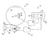
- FIG. 2is a schematic diagram of an exemplary safety system in the context of a machine having a circular blade.
- FIG. 3is a flowchart diagram of an exemplary self-test logic sequence according to the present invention.
- FIGS. 4A-Care flowchart diagrams of an exemplary self-test and operational sequence according to the present invention.
- FIG. 5is a schematic block diagram of a logic controller according to a first exemplary implementation of the present invention.
- FIG. 6is a schematic diagram of a user interface according to the present invention.
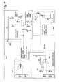
- FIG. 7is a schematic diagram of a firing capacitor charge and test circuit according to the first exemplary implementation of the present invention.
- FIG. 8is a schematic block diagram of a logic controller according to a second exemplary implementation of the present invention.
- FIG. 9is a schematic diagram of a firing capacitor charge and test circuit according to the second exemplary implementation of the present invention.
- FIG. 10is an isometric view of an exemplary pawl adapted for measuring pawl-to-blade spacing according to the present invention.
- FIG. 11is a schematic diagram of an exemplary circuit for detecting blade-to-pawl spacing according to the present invention.
- Machine 10may be any of a variety of different machines adapted for cutting workpieces, such as wood, including a table saw, miter saw (chop saw), radial arm saw, circular saw, band saw, jointer, planer, etc.
- Machine 10includes an operative structure 12 having a cutting tool 14 and a motor assembly 16 adapted to drive the cutting tool.
- Machine 10also includes a safety system 18 configured to minimize the potential of a serious injury to a person using machine 10 .
- Safety system 18is adapted to detect the occurrence of one or more dangerous conditions during use of machine 10 . If such a dangerous condition is detected, safety system 18 is adapted to engage operative structure 12 to limit any injury to the user caused by the dangerous condition.
- Machine 10also includes a suitable power source 20 to provide power to operative structure 12 and safety system 18 .
- Power source 20may be an external power source such as line current, or an internal power source such as a battery.
- power source 20may include a combination of both external and internal power sources.
- power source 20may include two or more separate power sources, each adapted to power different portions of machine 10 .
- operative structure 12may take any one of many different forms, depending on the type of machine 10 .
- operative structure 12may include a stationary housing configured to support motor assembly 16 in driving engagement with cutting tool 14 .
- operative structure 12may include a movable structure configured to carry cutting tool 14 between multiple operating positions.
- operative structure 12may include one or more transport mechanisms adapted to convey a workpiece toward and/or away from cutting tool 14 .
- Motor assembly 16includes one or more motors adapted to drive cutting tool 14 .
- the motorsmay be either directly or indirectly coupled to the cutting tool, and may also be adapted to drive workpiece transport mechanisms.
- Cutting tool 14typically includes one or more blades or other suitable cutting implements that are adapted to cut or remove portions from the workpieces.
- the particular form of cutting tool 14will vary depending upon the various embodiments of machine 10 .
- cutting tool 14will typically include one or more circular rotating blades having a plurality of teeth disposed along the perimetrical edge of the blade.
- the cutting tooltypically includes a plurality of radially spaced-apart blades.
- the cutting toolincludes an elongate, circuitous tooth-edged band.
- Safety system 18includes a detection subsystem 22 , a reaction subsystem 24 and a control subsystem 26 .
- Control subsystem 26may be adapted to receive inputs from a variety of sources including detection subsystem 22 , reaction subsystem 24 , operative structure 12 and motor assembly 16 .
- the control subsystemmay also include one or more sensors adapted to monitor selected parameters of machine 10 .
- control subsystem 26typically includes one or more instruments operable by a user to control the machine.
- the control subsystemis configured to control machine 10 in response to the inputs it receives.
- Detection subsystem 22is configured to detect one or more dangerous, or triggering, conditions during use of machine 10 .
- the detection subsystemmay be configured to detect that a portion of the user's body is dangerously close to, or in contact with, a portion of cutting tool 14 .
- the detection subsystemmay be configured to detect the rapid movement of a workpiece due to kickback by the cutting tool, as is described in U.S. Provisional Patent Application Ser. No. 60/182,866, the disclosure of which is herein incorporated by reference.
- detection subsystem 22may inform control subsystem 26 of the dangerous condition, which then activates reaction subsystem 24 .
- the detection subsystemmay be adapted to activate the reaction subsystem directly.
- reaction subsystem 24is configured to engage operative structure 12 quickly to prevent serious injury to the user. It will be appreciated that the particular action to be taken by reaction subsystem 24 will vary depending on the type of machine 10 and/or the dangerous condition that is detected. For example, reaction subsystem 24 may be configured to do one or more of the following: stop the movement of cutting tool 14 , disconnect motor assembly 16 from power source 20 , place a barrier between the cutting tool and the user, or retract the cutting tool from its operating position, etc. The reaction subsystem may be configured to take a combination of steps to protect the user from serious injury. Placement of a barrier between the cutting tool and teeth is described in more detail in U.S. Provisional Patent Application Ser. No.
- 60/225,206entitled “Cutting Tool Safety System,” filed Aug. 14, 2000 by SD3, LLC, the disclosure of which is herein incorporated by reference. Retraction of the cutting tool from its operating position is described in more detail in U.S. Provisional Patent Application Ser. No. 60/225,089, entitled “Retraction System For Use In Power Equipment,” filed Aug. 14, 2000 by SD3, LLC, the disclosure of which is herein incorporated by reference.
- reaction subsystem 24typically will vary depending on which action(s) are taken.
- reaction subsystem 24is configured to stop the movement of cutting tool 14 and includes a brake mechanism 28 , a biasing mechanism 30 , a restraining mechanism 32 , and a release mechanism 34 .
- Brake mechanism 28is adapted to engage operative structure 12 under the urging of biasing mechanism 30 .
- restraining mechanism 32holds the brake mechanism out of engagement with the operative structure.
- the brake mechanismupon receipt of an activation signal by reaction subsystem 24 , the brake mechanism is released from the restraining mechanism by release mechanism 34 , whereupon, the brake mechanism quickly engages at least a portion of the operative structure to bring the cutting tool to a stop.
- FIG. 2one example of the many possible implementations of safety system 18 is shown.
- System 18is configured to engage an operative structure having a cutting tool in the form of a circular blade 40 mounted on a rotating shaft or arbor 42 .
- Blade 40includes a plurality of cutting teeth (not shown) disposed around the outer edge of the blade.
- braking mechanism 28is adapted to engage the teeth of blade 40 and stop the rotation of the blade.
- detection subsystem 22is adapted to detect the dangerous condition of the user coming into contact with blade 40 .
- the detection subsystemincludes a sensor assembly, such as contact detection plates 44 and 46 , capacitively coupled to blade 40 to detect any contact between the user's body and the blade.
- the blade, or some larger portion of cutting tool 14is electrically isolated from the remainder of machine 10 .
- detection subsystem 22may include a different sensor assembly configured to detect contact in other ways, such as optically, resistively, etc.
- the detection subsystemis adapted to transmit a signal to control subsystem 26 when contact between the user and the blade is detected.
- Various exemplary embodiments and implementations of detection subsystem 22are described in more detail in U.S. Provisional Patent Application Ser. No.
- 60/225,200entitled “Contact Detection System For Power Equipment,” filed Aug. 14, 2000 by SD3, LLC, and U.S. Provisional Patent Application Ser. No. 60/225,211, entitled “Apparatus And Method For Detecting Dangerous Conditions In Power Equipment,” filed Aug. 14, 2000 by SD3, LLC, the disclosures of which are herein incorporated by reference.
- Control subsystem 26includes one or more instruments 48 that are operable by a user to control the motion of blade 40 .
- Instruments 48may include start/stop switches, speed controls, direction controls, etc.
- Control subsystem 26also includes a logic controller 50 connected to receive the user's inputs via instruments 48 .
- Logic controller 50is also connected to receive a contact detection signal from detection subsystem 22 . Further, the logic controller may be configured to receive inputs from other sources (not shown) such as blade motion sensors, workpiece sensors, etc. In any event, the logic controller is configured to control operative structure 12 in response to the user's inputs through instruments 48 .
- the logic controllerupon receipt of a contact detection signal from detection subsystem 22 , the logic controller overrides the control inputs from the user and activates reaction subsystem 24 to stop the motion of the blade.
- Various exemplary embodiments and implementations of logic controller 50will be described below.
- Various exemplary embodiments and implementations of a blade motion detection systemare described in U.S. Provisional Patent Application Ser. No. 60/225,094, entitled “Motion Detecting System For Use In Safety System For Power Equipment,” filed Aug. 14, 2000 by SD3, LLC, the disclosure of which is herein incorporated by reference.
- brake mechanism 28includes a pawl 60 mounted adjacent the edge of blade 40 and selectively moveable to engage and grip the teeth of the blade.
- Pawl 60may be constructed of any suitable material adapted to engage and stop the blade.
- the pawlmay be constructed of a relatively high strength thermoplastic material such as polycarbonate, ultrahigh molecular weight polyethylene (UHMW) or Acrylonitrile Butadiene Styrene (ABS), etc., or a metal such as aluminum, etc. It will be appreciated that the construction of pawl 60 will vary depending on the configuration of blade 40 . In any event, the pawl is urged into the blade by a biasing mechanism in the form of a spring 66 .
- pawl 60is pivoted into the teeth of blade 40 . It should be understood that sliding or rotary movement of pawl 60 may also be used.
- the springis adapted to urge pawl 60 into the teeth of the blade with sufficient force to grip the blade and quickly bring it to a stop.
- the pawlis held away from the edge of the blade by a restraining mechanism in the form of a fusible member 70 .
- the fusible memberis constructed of a suitable material adapted to restrain the pawl against the bias of spring 66 , and also adapted to melt under a determined electrical current density. Examples of suitable materials for fusible member 70 include NiChrome wire, stainless steel wire, etc.
- the fusible memberis connected between the pawl and a contact mount 72 .
- fusible member 70holds the pawl relatively close to the edge of the blade to reduce the distance the pawl must travel to engage the blade. Positioning the pawl relatively close to the edge of the blade reduces the time required for the pawl to engage and stop the blade.
- the pawlis held approximately 1/32-inch to 1 ⁇ 4-inch from the edge of the blade by fusible member 70 , however other pawl-to-blade spacings may also be used within the scope of the invention.
- Pawl 60is released from its unactuated, or cocked, position to engage blade 40 by a release mechanism in the form of a firing subsystem 76 .
- the firing subsystemis coupled to contact mount 72 , and is configured to melt fusible member 70 by passing a surge of electrical current through the fusible member.
- Firing subsystem 76is coupled to logic controller 50 and activated by a signal from the logic controller. When the logic controller receives a contact detection signal from detection subsystem 22 , the logic controller sends an activation signal to firing subsystem 76 , which melts fusible member 70 , thereby releasing the pawl to stop the blade.
- reaction subsystem 24are described in more detail in U.S. Provisional Patent Application Ser. No.
- safety system 18includes a replaceable cartridge 80 having a housing 82 .
- Pawl 60 , spring 66 , fusible member 70 and contact mount 72are all mounted within housing 82 .
- other portions of safety system 18may be mounted within the housing.
- safety system 18may be replaced separately or reused as appropriate.
- Various exemplary embodiments and implementations of a safety system using a replaceable cartridgeare described in more detail in U.S. Provisional Patent Application Ser. No. 60/225,201, entitled “Replaceable Brake Mechanism For Power Equipment,” filed Aug. 14, 2000 by SD3, LLC, and U.S. Provisional Patent Application Ser. No. 60/225,212, entitled “Brake Positioning System,” filed Aug. 14, 2000 by SD3, LLC, the disclosures of which are herein incorporated by reference.
- safety system 18While one particular implementation of safety system 18 has been described, it will be appreciated that many variations and modifications are possible within the scope of the invention. Many such variations and modifications are described in U.S. Provisional Patent Application Ser. Nos. 60/182,866 and 60/157,340, the disclosures of which are herein incorporated by reference.
- logic controller 50may be configured to perform a variety of functions depending on the particular type of machine 10 and/or the application.
- logic controller 50may be configured to conduct various self-test safety checks when the machine is switched on or off and during use, to ensure that detection subsystem 22 is operating properly and to prevent inadvertent triggering of reaction subsystem 24 .
- the logic controllermay be configured to control one or more display devices to inform a user of the status of machine 10 and safety system 18 .
- logic controller 50may be implemented in a variety of ways including using one or more custom application specific integrated circuits (ASICs), microprocessors, micro-controllers, digital logic circuits, and/or analog circuits, etc.
- ASICsapplication specific integrated circuits
- logic controller 50is configured to perform the self-check logic sequence shown in FIG. 3 .
- the exemplary sequencebegins when the user initially supplies power to the system, indicated at 901 .
- the logic systemfirst checks to determine whether the spacing between the blade and pawl is correct, as indicated at 902 .
- the blade-to-pawl spacingmay be measured by any suitable mechanism such as described in more detail below. If the spacing is outside acceptable limits, the system responds with an error signal, indicated at 903 .
- the error signalmay be an audible and/or visible signal, etc.
- control subsystemincludes a user interface adapted to indicate the status of the machine and annunciate any error conditions.
- the logic systemremains in the error state and prevents further operation of the machine until the correct blade-to-pawl spacing is detected.
- the logic systemdetermines whether the input signal produced on charge plate 44 by detection subsystem 22 is being detected at a sufficient amplitude on charge plate 46 , as indicated at 904 . This step ensures that the reaction subsystem will not be triggered accidentally upon start-up due to a fault in the detection subsystem, a grounded blade, incorrectly placed charge plates, etc. If the proper input signal is not detected, logic controller 50 responds with an error signal 903 . It will be appreciated that either the same or a different error signal may be produced for each fault condition.
- the logic controllerproceeds to determine whether a fusible member is present, as indicated at step 905 .
- the presence of a fusible membermay be determined by any suitable means such as described in more detail below. If no fusible member is present, logic controller 50 returns an error signal 903 . If a fusible member is detected, the logic controller then checks the electrical charge stored by firing subsystem 76 , as indicated at 906 . This step ensures that sufficient charge is present to melt the fusible member if the dangerous condition is detected. Exemplary circuitry for detecting sufficient charge is described in more detail below. If sufficient charge is not detected within a determined time period, the logic controller responds with an error signal 903 .
- logic controller 50allows power to be sent to motor assembly 16 , as indicated at 907 . It will be appreciated that the electrical sequence described above typically is completed within no more than a few seconds if no faults are detected.
- logic controller 50may be configured to perform any of a variety of checks during operation. For example, the rotation of the blade may be monitored by known mechanisms and the firing system may be disabled when the blade is not moving. This would allow the user to touch the blade when it is stopped without engaging brake mechanism 28 .
- Various exemplary embodiments and implementations of a blade motion detection systemare described in U.S. Provisional Application Ser. No. 60/225,094, entitled “Motion Detection System for Use in Safety System for Power Equipment,” filed Aug. 14, 2000, by SD3, LLC.
- logic controller 50may include a battery, a capacitor or other charge storage device to ensure the detection and reaction subsystems will continue to function at least temporarily after power to the machine is turned off.
- power to the motor assemblymay be shut off if an error occurs other than contact detection such as incorrect blade-to-charge plate spacing, insufficient charge on the charge storage devices, etc.
- logic controller 50may be implemented to provide any of a variety of safety and/or operational functions as desired.
- reaction subsystem 24is configured to stop cutting tool 14 upon contact with a user's body, it may also be desirable to stop motor assembly 16 , or at least the portion of the motor assembly adapted to drive the cutting tool, to prevent damage to the motor as it tries to drive the stalled cutting tool.
- motor assembly 16or at least the portion of the motor assembly adapted to drive the cutting tool, to prevent damage to the motor as it tries to drive the stalled cutting tool.
- machine 10typically is designed with the expectation that the cutting tool may stop due to binding, etc., it will usually be sufficient to turn off the motor assembly within a few seconds. This can be accomplished simply by cutting power to the motor.
- the logic controllermay be adapted to interrupt the circuit holding the magnetic contactor closed so that power to the motor is interrupted.
- this stepis optional, in that interrupting power to the machine's motor assembly is neither necessary nor sufficient to prevent serious injury to the user when the user touches the machine's cutting tool. Therefore, the principal benefit of this step is to reduce the likelihood of damaging the motor assembly or drive system while the brake system is preventing rotation or other movement of the cutting tool. It will be appreciated that there are many other suitable ways of stopping motor assembly 12 which are within the scope of the invention. As one example, power to the motor assembly may be controlled directly by safety stop 30 (e.g., through solid state on/off switches, etc.). This embodiment is described in more detail in U.S. Provisional Application Ser. No. 60/225,200, entitled “Contact Detection System for Power Equipment,” filed Aug. 14, 2000, by SD3, LLC. Also, it is possible to simply allow existing overload circuitry to trip in and turn off the stalled motor.
- safety stop 30e.g., through solid state on/off switches, etc.
- a suitable override controlmay include a mechanical switch between fusible member 70 and firing system 76 .
- the switchmay be a single-use switch configured to reset itself after each use.
- safety system 18may include sensors adjacent the workpiece to detect the presence of foil, green wood, etc., and disable the reaction subsystem automatically. This latter alternative relieves the user of having to remember to disable and re-enable the brake system.
- the override controlmay be configured in a variety of ways depending on the application and the level of safety desired.
- the override controlmay be configured to time-out (i.e., turn off) if the user does not switch the machine on within a predetermined time (e.g., 3, 5 or 10 seconds, etc.). This would prevent the user from actuating the override control and then becoming distracted before proceeding to cut the workpiece and forgetting the safety system had been disabled.
- a predetermined timee.g., 3, 5 or 10 seconds, etc.
- logic controller 50may be configured to require that the detection and reaction subsystems are operational before allowing the user to engage the override.
- the override controlis configured to reduce the likelihood that it will be actuated accidentally by the user.
- the override control switchmay be located away from the remaining operator switches and away from an area on machine 10 where the user is likely to accidentally bump against while using the machine.
- override control switch 48may include a cover or similar barrier which the user must remove or overcome before the switch can be actuated. Such covered switches are known to those of skill in the art.
- logic controller 50may be configured to produce a visual and/or audible alarm or warning when the override is actuated.
- logic controller 50may be configured to “pulse” the motor one or more times to alert the user that the blade is about to begin moving with the safety system disabled. This would alert a user, who accidentally actuated the override while in contact with the blade, to quickly move away from the blade.
- an alternative embodiment of logic controller 50may be configured to perform the self-test and detection logic shown schematically in FIGS. 4A-C .
- the main logic sequenceindicated generally at 910 in FIG. 4A , begins when machine 10 is first connected to power source 20 , as indicated at 911 .
- Logic controller 50begins sequence 910 by performing a system integrity check, as indicated at 912 .
- the system integrity checkmay include any one or more of a variety of checks which typically will vary depending on the particular type and configuration of machine 10 .
- system integrity check 912includes testing the sufficiency of power source 20 (here, standard line current) by any suitable means which are known to those of skill in the art.
- the system integrity checkmay also include driving the detection signal onto charge plate 44 and attempting to detect the signal at charge plate 46 . Failure to detect the detection signal at charge plate 46 may indicate a number of problems such as an electronic failure in detection subsystem 22 , a mis-positioned or grounded charge plate, grounded blade, etc.
- Exemplary system integrity check 912also includes a pawl-to-blade spacing test to ensure that pawl 60 is properly positioned adjacent blade 40 so that the pawl will engage and stop the blade if released. Exemplary mechanisms for detecting correct blade-to-pawl spacing are described in more detail below.
- logic controller 50turns motor assembly 16 off (if on), as indicated at 913 , and outputs an error signal to the user, as indicated at 914 . Once the user corrects the error and resets the logic controller (e.g., by disconnecting and then reconnecting the power to machine 10 ), the system integrity check is repeated.
- logic controller 50proceeds to check fusible member 70 as well as the stored charge in firing subsystem 76 , as indicated at 915 . If either the fusible member test or the stored charge test is negative, the logic controller turns off the motor assembly, indicated at 913 , and then outputs an error signal, indicated at 914 . It may be desirable to repeat step 915 one or more times, or provide a delay between steps 912 and 915 to ensure that firing subsystem 76 has sufficient time to build up the electrical charge.
- the logic controllerthen proceeds to one of two operational loops depending on whether the user-operable override switch has been activated, as indicated at 916 .
- testing for a user override signal after performing the fusible member/charge storage testprevents a user from overriding safety system 18 unless the safety system is functional.
- the safety systemis functional.
- step 915may be eliminated from the main operational loop. This would allow machine 10 to be operated regardless of whether safety system 18 was completely functional by engaging the override.
- logic controller 50proceeds to operate in an override loop, as indicated at 917 and detailed in FIG. 4B .
- logic controller 50first outputs a warning signal, as indicated at 918 and described above.
- the logic controllerchecks the status of START switch 48 , which is operable by a user to turn on motor assembly 16 .
- logic controller 50may be configured to read START switch 48 as being “on” only if it is actuated within a predetermined period after the override is enabled. If the START switch is “off,” logic controller 50 turns off the motor assembly (if on), as indicated at 920 , and exits the override loop as indicated at 921 .
- the logic controllerreturns to the system integrity check at the end of the override loop.
- the logic controllerwill continue to perform the system integrity check and the fusible member/stored charge tests until the START switch is actuated. This ensures that if a user engages the override and then delays actuating the START switch, the system will not turn on the motor assembly if a failure occurs between the time the override is enabled and the time the START switch is actuated.
- logic controllerproceeds to turn on motor assembly 16 , as indicated at 922 .
- the motor assemblyremains on until STOP switch 48 is actuated by the user, as indicated at 923 .
- logic controller 50turns off the motor assembly, as indicated at 920 , and exits the override loop at 921 .
- the logic controllerreturns to step 912 after exiting the override loop.
- detection loop 925is shown in detail in FIG. 4C .
- detection loop 925is depicted with two logic paths which are executed simultaneously. In a first path 926 the logic controller monitors detection subsystem 22 , while in a second path 927 the logic controller continually rechecks the fusible member and stored charge in firing subsystem 76 . This dual-path operation ensures that machine 10 will be shut down if a failure occurs while the blade is in motion. It will be appreciated by those of skill in the art that the dual-path operation may be implemented in a variety of ways including the use of interrupts, state machines, etc.
- the two pathsmay be implemented in a single sequential loop.
- testing of the stored chargeconsumes several milliseconds or even several seconds in some embodiments, it is typically desirable, in those embodiments, to execute both paths simultaneously so that several milliseconds or more do not pass between successive contact detection measurements.
- Path 927includes testing fusible member 70 and the charge stored by firing subsystem 76 , as indicated at 928 . This test is continuously repeated unless and until either the fusible member test or the stored charge test fails, at which point logic controller 50 turns the motor assembly off, as indicated at 929 , and outputs an error message, as indicated at 930 .
- the logic controlleralso stops executing test 928 when it exits the detection loop or when an error in path 926 occurs, as described below.
- the tests of fusible member 70 and firing subsystem 76 at step 928may be the same as, or different than, the tests that are used in the main loop at step 915 . In any event, the logic controller must be reset from step 930 , as described above.
- Path 926is the contact detection path and includes testing for excessive impedance loading on the blade, as indicated at 931 .
- Step 931ensures that power will not be supplied to the motor assembly if the capacitive load on the blade is so high that the detection subsystem might not be able to detect a contact between the blade and the user. This might occur for a variety of reasons. For example, if the blade is cutting highly dielectric materials (e.g., green wood), the capacitive load on the blade will increase. This issue is described in more detail in the incorporated references.
- highly dielectric materialse.g., green wood
- step 931ensures that the safety system will not allow the blade to begin rotating if the user is touching the blade when the START switch is actuated.
- the logic controlleris configured to set the value for excessive capacitive loading at approximately at least that amount of loading caused when a user contacts the blade.
- logic controller 50may be configured to recognize any desired amount of capacitive loading as being excessive.
- logic controller 50If the capacitive load on the blade is too high, logic controller 50 outputs an error signal, at 932 , and turns off motor assembly 16 (if on), as indicated at step 933 . The logic controller then exits the detection loop, at 934 , and returns to system integrity check 912 in the main operational loop shown in FIG. 4A . It will be appreciated that safety system 18 will not be enabled during the several seconds it takes the blade to spin down. This is because the capacitive loading is too high to accurately detect contact with the user, and is likely to trigger even though no contact has occurred. In alternative embodiments, the logic controller may continue to monitor for contact detection while the blade is rotating and actuate the firing system if contact is detected. Alternatively, the logic controller may be configured to actuate the firing system if the loading becomes too high.
- the logic controllermay nevertheless operate machine 10 by engaging the override. If the user does not actuate the override, safety system 18 will not supply power to motor assembly 16 until the capacitive loading problem is corrected.
- the logic controllerproceeds to test the contact detection signal from detection subsystem 22 , as indicated at 935 . If contact is detected, the logic controller determines whether the blade is rotating, as indicated at 936 . If the blade is rotating, the logic controller actuates the firing subsystem, at 937 , turns off motor assembly 16 , at 929 , and outputs an error, at 930 . The logic controller must then be reset as described above.
- the logic controlleroutputs an error signal, at step 932 , turns off the motor assembly (if on), at 933 , and exits the detection loop, at 934 .
- the safety systemwill detect the contact but will not actuate the firing subsystem. This allows a user to change or adjust the blade without actuating the brake.
- the userwould typically remove power from machine 10 before adjusting or replacing the blade, in which case, neither safety system 18 nor motor assembly 16 would be operable.
- logic controller 50checks the status of STOP switch 48 , as indicated at 938 . If the STOP switch is actuated, the logic controller turns off the motor assembly (if on), as indicated at 939 , and checks for blade rotation, as indicated at 940 . If the blade is rotating, the logic controller loops back to step 931 so that the contact detection is active as long as the blade continues to rotate. Thus, if a user actuates the STOP switch and then contacts the blade before it spins down, safety system 18 will react to stop the blade. Once the blade ceases to rotate, the logic controller exits the detection loop, as indicated at 934 .
- the logic controllerchecks the status of START switch 48 , as indicated at 941 . If the START switch has been actuated, the logic controller turns the motor assembly on (if off), and loops back to repeat the contact detection, as indicated at 942 . If the START switch has not been actuated, the logic controller turns off the motor assembly (if on), as indicated at 939 , and checks for blade rotation, at 940 . The logic controller continues to execute the detection loop until the blade stops, at which point the logic controller exits the detection loop, as indicated at 934 . Thus, the logic controller is configured to continuously monitor for contact detection whenever the blade is rotating and the user has not engaged the override.
- control subsystem 26 and logic controller 50may be implemented using many different components and many different configurations. Therefore, while two exemplary implementations are described below, it should be understood that any other suitable implementation may be used.
- Logic controller 50takes the form of a PIC16C63A-20/SO controller available from Microchip Technology, Inc., of Chandler, Ariz.
- the logic controlleris coupled to power source 20 , contact detection subsystem 22 , and a user interface 178 .
- the user interfacemay include any suitable mechanism adapted to display signals to a user and to allow a user to input signals to the logic controller. Examples of suitable user interface mechanisms which are known to those of skill in the art include lights, display screens, buzzers, sirens, switches, buttons, knobs, etc. In one exemplary embodiment depicted in FIG.
- user interface 178includes START, STOP, and OVERRIDE switches to allow the user to input control commands, and a pair of LED lights which indicate the system status.
- the LED lightsmay indicate system status in a variety of ways such as color, blinking, etc.
- the logic controlleris also connected to control motor assembly 16 via a suitable motor control circuit 174 , such as is described in more detail in U.S. Provisional Application Ser. No. 60/225,200, entitled “Contact Detection System for Power Equipment,” filed Aug. 14, 2000, by SD3, LLC, and to firing subsystem 76 .
- a suitable motor control circuit 174such as is described in more detail in U.S. Provisional Application Ser. No. 60/225,200, entitled “Contact Detection System for Power Equipment,” filed Aug. 14, 2000, by SD3, LLC, and to firing subsystem 76 .
- the logic controllerreceives a signal from detection subsystem 22 that contact between the user and blade has occurred, the logic controller actuates firing subsystem 76 and stops motor assembly 16 .
- the operation and testing sequencesare implemented by software instructions stored within, and executable by, the logic controller. It will be appreciated that the software instructions may take a variety of forms.
- the logic controller of the exemplary implementation depicted in FIG. 5is configured to conduct a variety of self-tests before enabling power to motor control 174 , as well as whenever the blade is moving.
- the logic controlleris configured to evaluate the line voltage supplied by power source 20 , and to shut off the motor if the voltage drops below a minimum value sufficient to operate the safety system.
- the logic controlleris also adapted to test the contact sense signal received from the detection subsystem to ensure the charge plates are correctly positioned, that the detection signal is properly coupled across the blade, and that the capacitive load on the blade is within defined limits.
- the logic controlleris also coupled to a blade rotation sense component 177 . Examples of suitable mechanisms for detecting blade rotation are described in U.S. Provisional Application Ser. No. 60/225,094, entitled “Motion Detection System for Use in Safety System for Power Equipment,” filed Aug. 14, 2000, by SD3, LLC.
- firing subsystem 76includes a single 390 ⁇ F firing capacitor 620 configured to discharge through fusible member 70 via a suitable SCR 621 connected to ground. Exemplary firing subsystems 76 are described in greater detail in U.S. Provisional Application Ser. No. 60/225,056, entitled “Firing Subsystem for Use in a Fast-Acting Safety System,” filed Aug. 14, 2000, by SD3, LLC.
- Buck-boost regulator 175includes a buck-boost charger 183 that steps up an 32-volt supply input to 180 volts for charging the firing capacitor.
- Logic controller 50provides a 125 khz input to control the buck-boost cycle of the charger.
- a regulator circuit 184monitors the voltage on the firing capacitor and turns charger 183 on or off as necessary to maintain the charge near 180 volts.
- Regulator circuit 184is constructed with a predetermined amount of hysteresis so that the charger will go on when the firing circuit voltage falls below 175 volts and turn off when the voltage reaches 180 volts, as set by the voltage divider inputs and feedback to comparator 185 .
- the output of comparator 185is fed to logic controller 50 .
- the logic controllermonitors both the time required to charge and to discharge the firing capacitor based on the state of the output of comparator 185 . Thus, the controller can verify that the firing capacitor is operating properly and storing adequate charge. If the firing capacitor cannot reach 180 volts quickly enough or discharges too rapidly, the logic controller determines that the firing capacitor or charging system has failed and takes appropriate action based on its programming.
- regulator circuit 184measures the voltage across the firing capacitor through fusible member 70 .
- the regulator circuitis also testing the integrity of the fusible member since a missing or failed fusible member would prevent the regulator circuit from detecting the voltage on the firing capacitor. While testing both the firing capacitor charge and fusible member with a single mechanism or test provides obvious savings of both processor cycle time and component costs, the fusible member may alternatively be tested separately from the firing capacitor charge.
- logic controller 50is implemented by a 87C752 controller available from Philips Semiconductor of Sunnyvale, Calif. As in the first exemplary implementation described above, the logic controller of the second implementation is coupled to power source 20 , contact detection subsystem 22 , firing subsystem 76 , user interface 178 , motor control 174 , and blade rotation sense 177 . Suitable examples of power source 20 , contact detection subsystem 22 , and motor control 174 are described in more detail in U.S. Provisional Application Ser. No. 60/225,200, entitled “Contact Detection System for Power Equipment,” filed Aug. 14, 2000, by SD3, LLC.
- Exemplary firing subsystems 76are described in more detail in U.S. Provisional Application Ser. No. 60/225,056, entitled “Firing Subsystem for Use in a Fast-Acting Safety System,” filed Aug. 14, 2000, by SD3, LLC.
- Exemplary circuitry and mechanisms for sensing blade rotationsare described in more detail in U.S. Provisional Application Ser. No. 60/225,094, entitled “Motion Detection System for Use in Safety System for Power Equipment,” filed Aug. 14, 2000, by SD3, LLC.
- the firing capacitor charging circuit for the second implementationis regulated by an enable line from logic controller 50 .
- the logic controllercan monitor the capacitor voltage through an output to an analog-to-digital converter (A/D) line on the logic controller.
- A/Danalog-to-digital converter
- the controllercan insure that the capacitance of the capacitor is sufficient to burn the fusible member.
- the logic controllermay be configured to measure the voltage on the firing capacitor at a plurality of discharge intervals to evaluate the integrity of the capacitor.
- the logic controllermeasures the capacitor voltage at three defined intervals during a discharge cycle, which should correspond to 3%, 5% and 7% of the full charge voltage.
- the logic controllermay be configured to interpret a low voltage at any of the discharge intervals as a failure, or may require a low voltage at two or more discharge intervals to indicate a failure.
- the logic controlleris configured to test the firing capacitor through fusible member 70 , thereby simultaneously testing the fusible member.
- the logic controllermay test the fusible member independently of the capacitor by monitoring the capacitor voltage during charging.
- logic controller 50may also be configured to monitor the pawl-to-blade spacing. It is well known in the art that many cutting tools such as saw blades do not have precisely uniform dimensions. As a result, when a new blade is installed on a saw, the pawl may no longer be correctly spaced from the blade. An incorrectly positioned pawl may slow the stopping speed of the pawl or prevent the pawl from stopping the blade. Therefore, to ensure the blade is stopped with uniform braking speed, it may be necessary to adjust the position of the pawl whenever a blade is replaced. Exemplary mechanisms and methods for automatically positioning the pawl are described in U.S. Provisional Application Ser. No. 60/225,212 entitled “Brake Positioning System,” filed Aug. 14, 2000, by SD3, LLC. However, regardless of whether the pawl is automatically positioned, configuring logic controller 50 to detect incorrect blade-to-pawl spacing provides an additional level of assurance that a user is protected against accidental contact with the blade.
- FIG. 10illustrates a pawl 945 having a capacitive system for detecting correct pawl spacing. Similar to pawl 40 shown in FIG. 2 , pawl 945 may include a portion 946 that is beveled or otherwise shaped to quickly and completely engage the teeth of a cutting tool. In addition, pawl 945 includes a pair of generally parallel, spaced-apart arms 947 which extend beyond portion 946 . Arms 947 are disposed to extend on either side of the blade, without touching the blade, when the pawl is in place adjacent the blade. Each arm includes a capacitor plate 826 disposed on the inside surface of the arm adjacent the blade. Conductive leads 949 run from each capacitor plate 826 to suitable blade detector circuitry (not shown).
- Capacitor plates 826are positioned on arms 947 such that, when the pawl spacing is within a desired range, the blade extends between the two capacitor plates. It will be appreciated that the capacitance across plates 826 will vary depending on whether the blade is positioned between the plates.
- the blade detector circuitryis configured to drive an electrical signal through conductive leads 949 and detect changes in the capacitance across the plates.
- Suitable circuitry that may be used with pawl 945is well known to those of skill in the art.
- One exemplary pawl-to-blade spacing detection circuitis indicated generally at 824 in FIG. 11 .
- a contact detection system suitable for use with the present inventionapplies an electrical signal to the blade via a drive plate (not shown).
- This signalcan be picked up by either or both of plates 826 and monitored to insure that it has an amplitude in a predetermined range.
- the amplitude detected by plates 826will fall off rapidly with distance from the blade. Therefore, by monitoring the detected amplitude, proper spacing can be verified. If the proper signal is not detected, circuit 824 conveys an error signal to logic controller 50 , which prevents operation of machine 10 until proper pawl-to-blade spacing is detected.
- Other examplesinclude circuits similar to the exemplary contact detection circuits described in U.S. Provisional Application Ser. No. 60/225,200, entitled “Contact Detection System for Power Equipment,” filed Aug. 14, 2000, by SD3, LLC.
- Capacitor plates 826can optionally be shaped to detect when the pawl is too close to the blade as well as not close enough. Alternatively, two pairs of capacitor plates may be positioned on the pawl: one pair to detect if the pawl is too close to the blade, and the other pair to detect if the pawl is too far from the blade. In any event, the detector circuitry is configured to transmit an error signal to logic controller 50 , which then takes appropriate action.
- both capacitor platesmay be positioned on the same side of the blade rather than on opposite sides.
- the capacitor plates and/or blade detection circuitrymay be separate from the pawl. In the latter case, for example, the capacitor plates and detection circuitry may be mounted on a separate electronics board associated with the pawl.
- the capacitor platesmay be replaced with one or more light-emitting diodes and detectors such that, when the pawl is properly positioned, the blade obstructs the optical path between the diodes and detectors. Other methods of detecting the proximity of the blade to the pawl are also possible.
- capacitor plates 826may function as charge plates 44 , 46 as well as pawl-spacing detectors.
- a detection platemay be mounted on beveled face 946 of the pawl. This plate can be used to detect the drive input signal used for contact detection. The amplitude of the signal detected at the plate will be inversely proportional to the space between the plate and the teeth of the blade. If this signal does not have an amplitude over a given threshold, the system would interpret this as indicating that the pawl face is not close enough to the blade.
- logic controller 50may also be configured to detect whether the cartridge is properly connected to the remainder of the safety system.
- One exemplary method of testing for an operable connection with the cartridgeis by testing a component mounted in the cartridge (e.g., the fusible link, charge stored by firing system, etc.).
- a cable (not shown) connecting cartridge 80 to logic controller 50may include a separate signal line which is grounded or otherwise biased when the cartridge is connected.
- the correct blade-to-pawl spacingmay be detected by measuring the blade-to-cartridge spacing.
- capacitor plates 826may be placed on cartridge housing 82 rather than on the pawl itself.
- failure of the blade-to-cartridge spacing testcould also be used to detect an inoperable connection to the cartridge.
- the present inventionprovides a reliable, effective and fast-acting system for preventing serious injuries to operators of power cutting machinery. While a few specific embodiments of safety system 18 and particularly control subsystem 26 have been described, those of skill in the art will appreciate that the present invention may be adapted in numerous ways for use in a wide variety of applications. Therefore, it will be understood that all such adaptations and applications are within the scope of the invention.
Landscapes
- Engineering & Computer Science (AREA)
- Life Sciences & Earth Sciences (AREA)
- Mechanical Engineering (AREA)
- Forests & Forestry (AREA)
- General Engineering & Computer Science (AREA)
- Wood Science & Technology (AREA)
- Sawing (AREA)
- Auxiliary Devices For Machine Tools (AREA)
Abstract
Description
Claims (21)
Priority Applications (36)
| Application Number | Priority Date | Filing Date | Title |
|---|---|---|---|
| US09/929,237US7600455B2 (en) | 2000-08-14 | 2001-08-13 | Logic control for fast-acting safety system |
| US10/047,066US6945148B2 (en) | 2000-09-29 | 2002-01-14 | Miter saw with improved safety system |
| US10/050,085US20020056349A1 (en) | 2000-09-29 | 2002-01-14 | Miter saw with improved safety system |
| US10/051,782US6877410B2 (en) | 2000-09-29 | 2002-01-15 | Miter saw with improved safety system |
| US10/052,274US6826988B2 (en) | 2000-09-29 | 2002-01-16 | Miter saw with improved safety system |
| US10/053,390US7377199B2 (en) | 2000-09-29 | 2002-01-16 | Contact detection system for power equipment |
| US10/052,806US6880440B2 (en) | 2000-09-29 | 2002-01-16 | Miter saw with improved safety system |
| US10/052,273US6813983B2 (en) | 2000-09-29 | 2002-01-16 | Power saw with improved safety system |
| US10/052,705US6994004B2 (en) | 2000-09-29 | 2002-01-16 | Table saw with improved safety system |
| US10/984,643US8061245B2 (en) | 2000-09-29 | 2004-11-08 | Safety methods for use in power equipment |
| US11/190,111US7357056B2 (en) | 2000-09-29 | 2005-07-25 | Cutting tool safety system |
| US11/218,356US7621205B2 (en) | 1999-10-01 | 2005-09-02 | Band saw with safety system |
| US11/348,580US20060123964A1 (en) | 2000-09-29 | 2006-02-06 | Table saw with improved safety system |
| US11/401,050US7788999B2 (en) | 1999-10-01 | 2006-04-10 | Brake mechanism for power equipment |
| US11/401,774US7525055B2 (en) | 1999-10-01 | 2006-04-11 | Switch box for power tools with safety systems |
| US11/445,548US7347131B2 (en) | 1999-10-01 | 2006-06-02 | Miter saw with improved safety system |
| US11/542,938US20070028733A1 (en) | 1999-10-01 | 2006-10-02 | Safety methods for use in power equipment |
| US12/154,675US7617752B2 (en) | 2000-09-29 | 2008-05-23 | Contact detection system for power equipment |
| US12/313,162US7789002B2 (en) | 2000-09-29 | 2008-11-17 | Table saw with improved safety system |
| US12/587,695US7921754B2 (en) | 2000-08-14 | 2009-10-09 | Logic control for fast-acting safety system |
| US12/590,924US8186255B2 (en) | 2000-09-29 | 2009-11-16 | Contact detection system for power equipment |
| US12/800,607US7895927B2 (en) | 1999-10-01 | 2010-05-19 | Power equipment with detection and reaction systems |
| US12/806,830US8191450B2 (en) | 2000-08-14 | 2010-08-20 | Power equipment with detection and reaction systems |
| US12/806,836US8196499B2 (en) | 1999-10-01 | 2010-08-20 | Power equipment with detection and reaction systems |
| US12/806,829US9522476B2 (en) | 1999-10-01 | 2010-08-20 | Power equipment with detection and reaction systems |
| US12/807,147US8402869B2 (en) | 1999-10-01 | 2010-08-27 | Brake mechanism for power equipment |
| US12/807,146US8291797B2 (en) | 1999-10-01 | 2010-08-27 | Table saw with improved safety system |
| US13/065,882US8151675B2 (en) | 2000-08-14 | 2011-03-31 | Logic control for fast-acting safety system |
| US13/442,290US8408106B2 (en) | 1999-10-01 | 2012-04-09 | Method of operating power equipment with detection and reaction systems |
| US13/442,259US8522655B2 (en) | 2000-08-14 | 2012-04-09 | Logic control for fast-acting safety system |
| US13/854,270US20170190012A9 (en) | 1999-10-01 | 2013-04-01 | Power equipment with detection and reaction systems |
| US14/013,618US9038515B2 (en) | 2000-08-14 | 2013-08-29 | Logic control for fast-acting safety system |
| US14/862,571US9925683B2 (en) | 1999-10-01 | 2015-09-23 | Table saws |
| US15/357,928US9969014B2 (en) | 1999-10-01 | 2016-11-21 | Power equipment with detection and reaction systems |
| US15/362,388US9878380B2 (en) | 1999-10-01 | 2016-11-28 | Table saw throat plates and table saws including the same |
| US15/935,395US10335972B2 (en) | 1999-10-01 | 2018-03-26 | Table Saws |
Applications Claiming Priority (15)
| Application Number | Priority Date | Filing Date | Title |
|---|---|---|---|
| US22520600P | 2000-08-14 | 2000-08-14 | |
| US22516900P | 2000-08-14 | 2000-08-14 | |
| US22508900P | 2000-08-14 | 2000-08-14 | |
| US22521000P | 2000-08-14 | 2000-08-14 | |
| US22521200P | 2000-08-14 | 2000-08-14 | |
| US22505800P | 2000-08-14 | 2000-08-14 | |
| US22509400P | 2000-08-14 | 2000-08-14 | |
| US22520000P | 2000-08-14 | 2000-08-14 | |
| US22517000P | 2000-08-14 | 2000-08-14 | |
| US22505900P | 2000-08-14 | 2000-08-14 | |
| US22521100P | 2000-08-14 | 2000-08-14 | |
| US22520100P | 2000-08-14 | 2000-08-14 | |
| US22505600P | 2000-08-14 | 2000-08-14 | |
| US22505700P | 2000-08-14 | 2000-08-14 | |
| US09/929,237US7600455B2 (en) | 2000-08-14 | 2001-08-13 | Logic control for fast-acting safety system |
Related Parent Applications (8)
| Application Number | Title | Priority Date | Filing Date |
|---|---|---|---|
| US09/929,236ContinuationUS7610836B2 (en) | 1999-10-01 | 2001-08-13 | Replaceable brake mechanism for power equipment |
| US09/929,235Continuation-In-PartUS7350444B2 (en) | 1999-10-01 | 2001-08-13 | Table saw with improved safety system |
| US09/929,237DivisionUS7600455B2 (en) | 1999-10-01 | 2001-08-13 | Logic control for fast-acting safety system |
| US09/929,238ContinuationUS20020017179A1 (en) | 1999-10-01 | 2001-08-13 | Miter saw with improved safety system |
| US09/929,238Continuation-In-PartUS20020017179A1 (en) | 1999-10-01 | 2001-08-13 | Miter saw with improved safety system |
| US09/929,234ContinuationUS7225712B2 (en) | 1999-10-01 | 2001-08-13 | Motion detecting system for use in a safety system for power equipment |
| US12/661,766ContinuationUS8051759B2 (en) | 1999-10-01 | 2010-03-22 | Motion detecting system for use in a safety system for power equipment |
| US13/854,270ContinuationUS20170190012A9 (en) | 1999-10-01 | 2013-04-01 | Power equipment with detection and reaction systems |
Related Child Applications (22)
| Application Number | Title | Priority Date | Filing Date |
|---|---|---|---|
| US09/929,236Continuation-In-PartUS7610836B2 (en) | 1999-10-01 | 2001-08-13 | Replaceable brake mechanism for power equipment |
| US09/929,238ContinuationUS20020017179A1 (en) | 1999-10-01 | 2001-08-13 | Miter saw with improved safety system |
| US09/929,238Continuation-In-PartUS20020017179A1 (en) | 1999-10-01 | 2001-08-13 | Miter saw with improved safety system |
| US09/929,236ContinuationUS7610836B2 (en) | 1999-10-01 | 2001-08-13 | Replaceable brake mechanism for power equipment |
| US09/929,237DivisionUS7600455B2 (en) | 1999-10-01 | 2001-08-13 | Logic control for fast-acting safety system |
| US10/050,085Continuation-In-PartUS20020056349A1 (en) | 1999-10-01 | 2002-01-14 | Miter saw with improved safety system |
| US10/047,066Continuation-In-PartUS6945148B2 (en) | 1999-10-01 | 2002-01-14 | Miter saw with improved safety system |
| US10/051,782Continuation-In-PartUS6877410B2 (en) | 1999-10-01 | 2002-01-15 | Miter saw with improved safety system |
| US10/052,274Continuation-In-PartUS6826988B2 (en) | 2000-09-29 | 2002-01-16 | Miter saw with improved safety system |
| US10/053,390Continuation-In-PartUS7377199B2 (en) | 1999-10-01 | 2002-01-16 | Contact detection system for power equipment |
| US10/052,273Continuation-In-PartUS6813983B2 (en) | 2000-09-29 | 2002-01-16 | Power saw with improved safety system |
| US10/052,705Continuation-In-PartUS6994004B2 (en) | 1999-10-01 | 2002-01-16 | Table saw with improved safety system |
| US10/052,806Continuation-In-PartUS6880440B2 (en) | 1999-10-01 | 2002-01-16 | Miter saw with improved safety system |
| US10/984,643ContinuationUS8061245B2 (en) | 1999-10-01 | 2004-11-08 | Safety methods for use in power equipment |
| US11/190,111ContinuationUS7357056B2 (en) | 1999-10-01 | 2005-07-25 | Cutting tool safety system |
| US11/218,356ContinuationUS7621205B2 (en) | 1999-10-01 | 2005-09-02 | Band saw with safety system |
| US11/401,050ContinuationUS7788999B2 (en) | 1999-10-01 | 2006-04-10 | Brake mechanism for power equipment |
| US11/401,774ContinuationUS7525055B2 (en) | 1999-10-01 | 2006-04-11 | Switch box for power tools with safety systems |
| US11/445,548ContinuationUS7347131B2 (en) | 1999-10-01 | 2006-06-02 | Miter saw with improved safety system |
| US11/542,938ContinuationUS20070028733A1 (en) | 1999-10-01 | 2006-10-02 | Safety methods for use in power equipment |
| US12/587,695DivisionUS7921754B2 (en) | 1999-10-01 | 2009-10-09 | Logic control for fast-acting safety system |
| US12/587,695ContinuationUS7921754B2 (en) | 1999-10-01 | 2009-10-09 | Logic control for fast-acting safety system |
Publications (2)
| Publication Number | Publication Date |
|---|---|
| US20020020262A1 US20020020262A1 (en) | 2002-02-21 |
| US7600455B2true US7600455B2 (en) | 2009-10-13 |
Family
ID=27585533
Family Applications (5)
| Application Number | Title | Priority Date | Filing Date |
|---|---|---|---|
| US09/929,237Expired - LifetimeUS7600455B2 (en) | 1999-10-01 | 2001-08-13 | Logic control for fast-acting safety system |
| US12/587,695Expired - Fee RelatedUS7921754B2 (en) | 1999-10-01 | 2009-10-09 | Logic control for fast-acting safety system |
| US13/065,882Expired - Fee RelatedUS8151675B2 (en) | 1999-10-01 | 2011-03-31 | Logic control for fast-acting safety system |
| US13/442,259Expired - Fee RelatedUS8522655B2 (en) | 1999-10-01 | 2012-04-09 | Logic control for fast-acting safety system |
| US14/013,618Expired - Fee RelatedUS9038515B2 (en) | 1999-10-01 | 2013-08-29 | Logic control for fast-acting safety system |
Family Applications After (4)
| Application Number | Title | Priority Date | Filing Date |
|---|---|---|---|
| US12/587,695Expired - Fee RelatedUS7921754B2 (en) | 1999-10-01 | 2009-10-09 | Logic control for fast-acting safety system |
| US13/065,882Expired - Fee RelatedUS8151675B2 (en) | 1999-10-01 | 2011-03-31 | Logic control for fast-acting safety system |
| US13/442,259Expired - Fee RelatedUS8522655B2 (en) | 1999-10-01 | 2012-04-09 | Logic control for fast-acting safety system |
| US14/013,618Expired - Fee RelatedUS9038515B2 (en) | 1999-10-01 | 2013-08-29 | Logic control for fast-acting safety system |
Country Status (1)
| Country | Link |
|---|---|
| US (5) | US7600455B2 (en) |
Cited By (49)
| Publication number | Priority date | Publication date | Assignee | Title |
|---|---|---|---|---|
| US20090236012A1 (en)* | 2007-12-31 | 2009-09-24 | Gass Stephen F | Detection systems for power equipment |
| US20100206145A1 (en)* | 2008-09-08 | 2010-08-19 | Power Tool Institute | Detection system for power tool |
| US20110005537A1 (en)* | 2009-01-13 | 2011-01-13 | Wei Hsu | Nail Clipping Device with a Warning Module |
| US20110048192A1 (en)* | 2009-08-26 | 2011-03-03 | Credo Technology Corporation | Table saw with mechanical fuse |
| US20110048207A1 (en)* | 2009-08-26 | 2011-03-03 | Credo Technology Corporation | Table saw with linkage drop system |
| US20110048199A1 (en)* | 2009-08-26 | 2011-03-03 | Robert Bosch Tool Corporation | Table saw riving knife |
| US20110048195A1 (en)* | 2009-08-26 | 2011-03-03 | Credo Technology Corporation | Table saw with ratchet mechanism |
| US20110048194A1 (en)* | 2009-08-26 | 2011-03-03 | Credo Technology Corporation | Table saw with reset mechanism |
| WO2011040957A1 (en) | 2009-10-02 | 2011-04-07 | Sd3, Llc | Actuators for power tool safety systems |
| US8186258B2 (en) | 2009-08-26 | 2012-05-29 | Robert Bosch Gmbh | Table saw with actuator reset mechanism |
| US8245612B2 (en) | 2009-08-26 | 2012-08-21 | Robert Bosch Gmbh | Table saw with swing arm support |
| US8286537B2 (en) | 2009-08-26 | 2012-10-16 | Robert Bosch Gmbh | Table saw with pressure operated actuator |
| US8316748B2 (en) | 2009-08-26 | 2012-11-27 | Robert Bosch Gmbh | Table saw with alignment plate |
| US8919231B2 (en) | 2008-11-19 | 2014-12-30 | Power Tool Institute | Safety mechanisms for power tools |
| US20150121828A1 (en)* | 2012-06-12 | 2015-05-07 | Cnh Industrial America Llc | Agricultural Vehicle with an Improved Access Panel Lock |
| US9079258B2 (en) | 2009-08-26 | 2015-07-14 | Robert Bosch Gmbh | Table saw with belt stop |
| US20150330470A1 (en)* | 2013-01-25 | 2015-11-19 | Knorr-Bremse Systeme Fuer Nutzfahrzeuge Gmbh | Disc Brake Having a Clearance-Monitoring Device, and Method for Monitoring Clearance |
| US20160008997A1 (en)* | 1999-10-01 | 2016-01-14 | Sd3, Llc | Table saws |
| US20160263683A1 (en)* | 2015-03-12 | 2016-09-15 | Robert Bosch Tool Corporation | Power Tool with Drop Arm Orbit Bracket |
| US20160263679A1 (en)* | 2015-03-12 | 2016-09-15 | Robert Bosch Tool Corporation | Power Tool Motor with Reduced Electrical Noise |
| US9511429B2 (en) | 2013-03-15 | 2016-12-06 | Robert BoschTool Corporation | Blade drop for power device and method of manufacturing thereof |
| US9517516B2 (en) | 2013-03-14 | 2016-12-13 | Robert Bosch Tool Corporation | Blade drop power tool with dust management |
| US9623498B2 (en) | 2003-12-31 | 2017-04-18 | Sd3, Llc | Table saws |
| US9687922B2 (en) | 2015-03-12 | 2017-06-27 | Robert Bosch Tool Corporation | Power tool with cammed throat plate |
| US9724840B2 (en) | 1999-10-01 | 2017-08-08 | Sd3, Llc | Safety systems for power equipment |
| US9849527B2 (en)* | 2015-03-12 | 2017-12-26 | Robert Bosch Tool Corporation | Power tool with lightweight actuator housing |
| US9868166B2 (en) | 2015-03-12 | 2018-01-16 | Robert Bosch Tool Corporation | Power tool with pyrotechnic lockout |
| US9914239B2 (en) | 2015-03-12 | 2018-03-13 | Robert Bosch Tool Corporation | User interface system in a table saw |
| US9927796B2 (en) | 2001-05-17 | 2018-03-27 | Sawstop Holding Llc | Band saw with improved safety system |
| US9969013B2 (en) | 2009-08-26 | 2018-05-15 | Robert Bosch Tool Corporation | Table saw with actuator module |
| US9969015B2 (en) | 2015-03-12 | 2018-05-15 | Robert Bosch Tool Corporation | Power tool with protected coupling plate |
| US10029386B2 (en) | 2009-08-26 | 2018-07-24 | Robert Bosch Tool Corporation | Table saw with positive locking mechanism |
| US10071432B2 (en) | 2015-03-12 | 2018-09-11 | Robert Bosch Tool Corporation | Power tool with arbor lock |
| US10076796B2 (en) | 2009-08-26 | 2018-09-18 | Robert Bosch Tool Corporation | Table saw with dust shield |
| US10099399B2 (en) | 2015-03-12 | 2018-10-16 | Robert Bosch Tool Corporation | Object proximity detection in a saw |
| US10105863B2 (en) | 2015-03-12 | 2018-10-23 | Robert Bosch Tool Corporation | System and method for object and operator profiling in an object detection system in a saw |
| US10189098B2 (en) | 2015-03-12 | 2019-01-29 | Robert Bosch Tool Corporation | Diagnostic and maintenance operation for a saw |
| US10213853B2 (en) | 2015-03-12 | 2019-02-26 | Robert Bosch Tool Corporation | Power tool drop arm with offset ribbing |
| US10322522B2 (en) | 2015-03-12 | 2019-06-18 | Robert Bosch Tool Corporation | Electrical configuration for object detection system in a saw |
| US10369642B2 (en) | 2015-03-12 | 2019-08-06 | Robert Bosch Tool Corporation | Power tool with protected circuit board orientation |
| US10427227B2 (en) | 2015-03-12 | 2019-10-01 | Robert Bosch Tool Corporation | Drop arm reset method |
| US10758989B2 (en) | 2015-03-12 | 2020-09-01 | Robert Bosch Tool Corporation | System and method for sensing cable fault detection in a saw |
| US10786854B2 (en) | 2015-03-12 | 2020-09-29 | Robert Bosch Tool Corporation | Table saw with electrically isolated arbor shaft |
| US10799964B2 (en) | 2015-03-12 | 2020-10-13 | Robert Bosch Tool Corporation | Table saw with pulley alignment mechanism |
| US10821529B2 (en) | 2015-03-12 | 2020-11-03 | Robert Bosch Tool Corporation | Power tool with improved belt tensioning |
| US10865941B2 (en) | 2018-11-20 | 2020-12-15 | Dennis E. Lewis | Safety system and method for power tools |
| US11085582B2 (en) | 2017-08-30 | 2021-08-10 | Milwaukee Electric Tool Corporation | Power tool having object detection |
| EP4338908A2 (en) | 2016-05-31 | 2024-03-20 | SawStop Holding LLC | Detection systems for power tools with active injury mitigation technology |
| US12232744B2 (en) | 2019-07-15 | 2025-02-25 | Stryker Corporation | Robotic hand-held surgical instrument systems and methods |
Families Citing this family (74)
| Publication number | Priority date | Publication date | Assignee | Title |
|---|---|---|---|---|
| US7610836B2 (en)* | 2000-08-14 | 2009-11-03 | Sd3, Llc | Replaceable brake mechanism for power equipment |
| US7000514B2 (en) | 2001-07-27 | 2006-02-21 | Sd3, Llc | Safety systems for band saws |
| US8065943B2 (en) | 2000-09-18 | 2011-11-29 | Sd3, Llc | Translation stop for use in power equipment |
| US7171879B2 (en)* | 2001-07-02 | 2007-02-06 | Sd3, Llc | Discrete proximity detection system |
| US7024975B2 (en)* | 2000-08-14 | 2006-04-11 | Sd3, Llc | Brake mechanism for power equipment |
| US7350445B2 (en) | 2003-08-20 | 2008-04-01 | Sd3, Llc | Brake cartridge for power equipment |
| US6877410B2 (en) | 2000-09-29 | 2005-04-12 | Sd3, Llc | Miter saw with improved safety system |
| US6994004B2 (en) | 2000-09-29 | 2006-02-07 | Sd3, Llc | Table saw with improved safety system |
| US8061245B2 (en) | 2000-09-29 | 2011-11-22 | Sd3, Llc | Safety methods for use in power equipment |
| US20030037651A1 (en) | 2001-08-13 | 2003-02-27 | Gass Stephen F. | Safety systems for power equipment |
| US7353737B2 (en) | 2001-08-13 | 2008-04-08 | Sd3, Llc | Miter saw with improved safety system |
| US6945149B2 (en) | 2001-07-25 | 2005-09-20 | Sd3, Llc | Actuators for use in fast-acting safety systems |
| US7077039B2 (en) | 2001-11-13 | 2006-07-18 | Sd3, Llc | Detection system for power equipment |
| US7481140B2 (en) | 2005-04-15 | 2009-01-27 | Sd3, Llc | Detection systems for power equipment |
| US7197969B2 (en)* | 2001-09-24 | 2007-04-03 | Sd3, Llc | Logic control with test mode for fast-acting safety system |
| US7472634B2 (en) | 2003-08-20 | 2009-01-06 | Sd3, Llc | Woodworking machines with overmolded arbors |
| US7308843B2 (en)* | 2000-08-14 | 2007-12-18 | Sd3, Llc | Spring-biased brake mechanism for power equipment |
| US7290472B2 (en) | 2002-01-14 | 2007-11-06 | Sd3, Llc | Miter saw with improved safety system |
| US20030056853A1 (en) | 2001-09-21 | 2003-03-27 | Gass Stephen F. | Router with improved safety system |
| US8459157B2 (en) | 2003-12-31 | 2013-06-11 | Sd3, Llc | Brake cartridges and mounting systems for brake cartridges |
| US7231856B2 (en)* | 2001-06-13 | 2007-06-19 | Sd3, Llc | Apparatus and method for detecting dangerous conditions in power equipment |
| US20050041359A1 (en)* | 2003-08-20 | 2005-02-24 | Gass Stephen F. | Motion detecting system for use in a safety system for power equipment |
| US6945148B2 (en) | 2000-09-29 | 2005-09-20 | Sd3, Llc | Miter saw with improved safety system |
| US6857345B2 (en) | 2000-08-14 | 2005-02-22 | Sd3, Llc | Brake positioning system |
| US7827890B2 (en) | 2004-01-29 | 2010-11-09 | Sd3, Llc | Table saws with safety systems and systems to mount and index attachments |
| US6957601B2 (en) | 2000-08-14 | 2005-10-25 | Sd3, Llc | Translation stop for use in power equipment |
| US6880440B2 (en) | 2000-09-29 | 2005-04-19 | Sd3, Llc | Miter saw with improved safety system |
| US7536238B2 (en) | 2003-12-31 | 2009-05-19 | Sd3, Llc | Detection systems for power equipment |
| US7055417B1 (en) | 1999-10-01 | 2006-06-06 | Sd3, Llc | Safety system for power equipment |
| US7712403B2 (en) | 2001-07-03 | 2010-05-11 | Sd3, Llc | Actuators for use in fast-acting safety systems |
| US7836804B2 (en)* | 2003-08-20 | 2010-11-23 | Sd3, Llc | Woodworking machines with overmolded arbors |
| US7377199B2 (en) | 2000-09-29 | 2008-05-27 | Sd3, Llc | Contact detection system for power equipment |
| US6826988B2 (en) | 2000-09-29 | 2004-12-07 | Sd3, Llc | Miter saw with improved safety system |
| US6813983B2 (en) | 2000-09-29 | 2004-11-09 | Sd3, Llc | Power saw with improved safety system |
| US6900728B2 (en)* | 2002-07-29 | 2005-05-31 | Home Depot U.S.A., Inc. | System to detect user entry into a defined danger zone |
| US20040060404A1 (en)* | 2002-09-30 | 2004-04-01 | Emerson Electric Co. | Breakaway hub for saw |
| CA2448479C (en)* | 2002-11-12 | 2009-05-05 | Makita Corporation | Power tools |
| US20040123709A1 (en)* | 2002-12-30 | 2004-07-01 | Emerson Electric Co. | System for sensing user contact with a saw blade |
| US20040194594A1 (en)* | 2003-01-31 | 2004-10-07 | Dils Jeffrey M. | Machine safety protection system |
| US6922153B2 (en) | 2003-05-13 | 2005-07-26 | Credo Technology Corporation | Safety detection and protection system for power tools |
| JP2005088248A (en)* | 2003-09-12 | 2005-04-07 | Makita Corp | Power tool |
| US7347851B1 (en) | 2004-03-09 | 2008-03-25 | Leo B Kriksunov | Needleless hypodermic jet injector apparatus and method |
| US7661614B2 (en)* | 2004-09-10 | 2010-02-16 | Fellowes Inc. | Shredder throat safety system |
| US7311276B2 (en)* | 2004-09-10 | 2007-12-25 | Fellowes Inc. | Shredder with proximity sensing system |
| US7631822B2 (en) | 2004-09-10 | 2009-12-15 | Fellowes Inc. | Shredder with thickness detector |
| US7628101B1 (en) | 2006-03-13 | 2009-12-08 | Power Tool Institute | Pyrotechnic drop mechanism for power tools |
| WO2007009172A1 (en)* | 2005-07-18 | 2007-01-25 | Bladestop Pty Limited | Electric saw with operator protection system |
| GB2437594B (en)* | 2006-04-24 | 2010-08-11 | Acco Uk Ltd | A shredding machine |
| CN2915259Y (en)* | 2006-07-14 | 2007-06-27 | 上海震旦办公设备有限公司 | Paper shredder touch safety device |
| US8008812B2 (en) | 2006-07-14 | 2011-08-30 | Aurora Office Equipment Co., Ltd. | Paper shredder control system responsive to touch-sensitive element |
| US8060235B2 (en) | 2006-08-18 | 2011-11-15 | Kevin M Johnson | Saw adjustment mechanism |
| US7757982B2 (en)* | 2006-09-28 | 2010-07-20 | Fellowes, Inc. | Shredder with intelligent activation switch |
| GB2451513B (en) | 2007-08-02 | 2012-04-18 | Acco Uk Ltd | A shredding machine |
| US9063289B1 (en) | 2008-06-30 | 2015-06-23 | Nlight Photonics Corporation | Multimode fiber combiners |
| CN201244502Y (en) | 2008-08-19 | 2009-05-27 | 上海震旦办公设备有限公司 | Structure capable of removing nail of automatic paper crusher |
| CN101543799B (en)* | 2009-04-28 | 2012-10-10 | 上海震旦办公设备有限公司 | Novel protector for paper crusher |
| CN101543800A (en)* | 2009-05-07 | 2009-09-30 | 上海震旦办公设备有限公司 | Paper jamming prevention protective device of paper shredder |
| US9494738B1 (en) | 2009-05-28 | 2016-11-15 | Nlight, Inc. | Single mode fiber combiners |
| US8534174B2 (en) | 2010-09-27 | 2013-09-17 | Power Tool Institute | Pyrotechnic actuator and power cutting tool with safety reaction system having such pyrotechnic actuator |
| US8723468B2 (en) | 2011-04-28 | 2014-05-13 | Aurora Office Equipment Co., Ltd. | Cooled motor |
| US8708260B2 (en) | 2011-08-08 | 2014-04-29 | Aurora Office Equipment Co., Ltd. | Depowered standby paper shredder and method |
| DE102012212754B4 (en)* | 2012-06-29 | 2022-03-03 | Robert Bosch Gmbh | Method for operating a sensor system and sensor system |
| EP2919935B1 (en)* | 2012-11-13 | 2018-05-30 | Robert Bosch GmbH | Workpiece presence and/or height detection system and blade guard detection system |
| CN103042556B (en)* | 2012-12-25 | 2015-02-25 | 深圳大学 | Synchronous control method of high-speed paper delivering system and paper cutting system of honeycomb paper cutting device |
| WO2014105756A1 (en) | 2012-12-31 | 2014-07-03 | Nlight Photonics Corporation | Spatially stable high brightness fiber |
| WO2014105757A1 (en) | 2012-12-31 | 2014-07-03 | Nlight Photonics Corporation | All fiber low dynamic pointing high power lma fiber amplifier |
| US9381664B2 (en) | 2013-03-14 | 2016-07-05 | Robert Bosch Gmbh | Rotating saw with balanced dynamic braking |
| WO2014160315A1 (en) | 2013-03-14 | 2014-10-02 | Robert Bosch Gmbh | Miter saw with active control energy dampener |
| JP6181450B2 (en)* | 2013-07-24 | 2017-08-16 | 株式会社マキタ | Reciprocating power tool |
| TWI549776B (en)* | 2014-05-02 | 2016-09-21 | 邱智煇 | A protective apparatus and a machine tool |
| WO2019055049A1 (en)* | 2017-09-18 | 2019-03-21 | Robert Bosch Tool Corporation | Method to ensure safety critical functionality for an electrically powered machine |
| EP3750673B1 (en)* | 2019-06-10 | 2021-09-29 | Nanjing Chervon Industry Co., Ltd. | Power tool |
| US20220266363A1 (en)* | 2021-02-25 | 2022-08-25 | Nan John Electrical Co., Ltd. | Human-body-defined security recognition system of processing machine |
| US11958152B2 (en) | 2021-04-19 | 2024-04-16 | Masonite Corporation | Safety system for miter saw and method of use thereof |
Citations (559)
| Publication number | Priority date | Publication date | Assignee | Title |
|---|---|---|---|---|
| US146886A (en) | 1874-01-27 | Improvement in sawing-machines | ||
| US162814A (en) | 1875-05-04 | Improvement in saw-guards | ||
| US261090A (en) | 1882-07-11 | Circular-saw guard | ||
| US264412A (en) | 1882-09-12 | Half to john h | ||
| US299480A (en) | 1884-05-27 | Saw-guard | ||
| US302041A (en) | 1884-07-15 | Saw-guard | ||
| US307112A (en) | 1884-10-28 | Saw-guard | ||
| US509253A (en) | 1893-11-21 | Safety-guard for rip-saws | ||
| US545504A (en) | 1895-09-03 | Saw-guard | ||
| US869513A (en) | 1907-06-17 | 1907-10-29 | Frederick C Pfeil | Saw-guard. |
| US941726A (en) | 1907-10-15 | 1909-11-30 | Charles F Pfalzgraf | Safety trip device for power-operated machines. |
| US982312A (en) | 1910-02-04 | 1911-01-24 | Edmond O Swafford | Wood-sawing machine. |
| US997720A (en) | 1909-08-07 | 1911-07-11 | Othon Troupenat | Safety device for saws. |
| US1037843A (en) | 1911-10-30 | 1912-09-10 | David S Ackley | Saw-guard |
| US1050649A (en) | 1910-05-28 | 1913-01-14 | Crescent Machine Company | Saw-guard. |
| US1054558A (en) | 1912-07-29 | 1913-02-25 | Nye Company | Self-adjusting support for circular-saw and shaper guards. |
| US1074198A (en) | 1913-03-21 | 1913-09-30 | Francis Vosburgh Phillips | Saw-guard. |
| US1082870A (en) | 1912-11-20 | 1913-12-30 | John W Humason | Saw-guard. |
| US1101515A (en) | 1913-06-27 | 1914-06-30 | George H Adam | Safety saw-guard. |
| US1126970A (en) | 1913-02-10 | 1915-02-02 | Eastman Kodak Co | Saw-guard. |
| US1132129A (en) | 1914-06-15 | 1915-03-16 | Fred M Stevens | Safety-grip for circular saws. |
| US1148169A (en) | 1913-01-06 | 1915-07-27 | Andrew F Howe | Saw-guard. |
| US1154209A (en) | 1914-08-11 | 1915-09-21 | John L Rushton | Saw-guard. |
| US1205246A (en) | 1913-10-27 | 1916-11-21 | Int Harvester Canada | Shipping-package. |
| US1228047A (en) | 1916-12-18 | 1917-05-29 | Darwin O Reinhold | Self-adjusting spreader for saws. |
| US1240430A (en) | 1916-07-22 | 1917-09-18 | Peter Erickson | Cutter-guard. |
| US1244187A (en) | 1917-02-17 | 1917-10-23 | Warren M Frisbie | Circular-saw guard. |
| US1255886A (en) | 1915-11-23 | 1918-02-12 | Emerald E Jones | Saw-guard. |
| US1258961A (en) | 1916-03-09 | 1918-03-12 | James G Tattersall | Saw-guard and splitter. |
| US1311508A (en) | 1919-07-29 | Planooraph co | ||
| US1324136A (en) | 1919-12-09 | Tool-operating machine | ||
| US1381612A (en) | 1919-10-24 | 1921-06-14 | George A Anderson | Saw-guard |
| US1397606A (en) | 1918-07-29 | 1921-11-22 | Christian N Smith | Safety-shield for circular saws |
| US1427005A (en) | 1919-12-26 | 1922-08-22 | James D Mcmichael | Saw guard |
| US1430983A (en) | 1921-10-05 | 1922-10-03 | Granberg Wilhelm | Guard for sawing machines |
| US1450906A (en) | 1919-07-28 | 1923-04-10 | Charles W Anderson | Power control for saw tables and the like |
| US1465224A (en) | 1921-07-22 | 1923-08-14 | Lantz Joseph Edward | Automatic shield for circular saws |
| US1464924A (en) | 1922-06-20 | 1923-08-14 | William D Drummond | Saw guard |
| US1492145A (en) | 1922-12-29 | 1924-04-29 | Randal E Talley | Composite gear wheel |
| US1496212A (en) | 1923-02-06 | 1924-06-03 | James F Sullivan | Circular-saw guard |
| US1511797A (en) | 1924-02-15 | 1924-10-14 | Frank E Berghold | Saw guard |
| US1526128A (en) | 1923-10-20 | 1925-02-10 | Flohr Andrew | Saw guard |
| US1527587A (en) | 1923-12-07 | 1925-02-24 | Hutchinson Frank | Saw guard |
| US1551900A (en) | 1924-12-05 | 1925-09-01 | Robert L Morrow | Safety device |
| US1553996A (en) | 1924-04-19 | 1925-09-15 | Federer Joseph | Safety saw guard |
| US1582483A (en) | 1925-01-13 | 1926-04-27 | Geniah B Runyan | Meat cutter |
| US1590988A (en) | 1924-09-24 | 1926-06-29 | Wheland Company | Combined setwork and recede for sawmill carriages |
| US1600604A (en) | 1926-03-06 | 1926-09-21 | Sorlien Andrew | Board holder for sawing machines |
| US1616478A (en) | 1926-01-19 | 1927-02-08 | Julius C Reiche | Guard for circular saws |
| US1640517A (en) | 1924-04-17 | 1927-08-30 | Paine Lumber Company Ltd | Saw guard |
| US1662372A (en) | 1926-04-26 | 1928-03-13 | Abraham D Ward | Saw guard |
| US1668061A (en) | 1926-08-11 | 1928-05-01 | Fred B Falkins | Universal woodworking machine |
| US1701948A (en) | 1925-04-02 | 1929-02-12 | Crowe Mfg Corp | Portable saw |
| US1711490A (en) | 1927-09-12 | 1929-05-07 | William D Drummond | Saw guard |
| US1712828A (en) | 1927-02-14 | 1929-05-14 | Henry J Klehm | Saw guard |
| US1774521A (en) | 1928-10-31 | 1930-09-02 | Wilbur S Neighbour | Saw guard |
| US1807120A (en) | 1929-03-11 | 1931-05-26 | Hall & Brown Wood Working Mach | Saw |
| US1811066A (en) | 1929-02-23 | 1931-06-23 | Carl E Tannewitz | Sawing machine |
| US1879280A (en) | 1930-08-30 | 1932-09-27 | George V James | Guard for circular saws |
| US1896924A (en) | 1933-02-07 | Table fob saws ob the like | ||
| US1902270A (en) | 1932-06-02 | 1933-03-21 | Delta Mfg Co | Miter gauge |
| US1904005A (en) | 1932-02-03 | 1933-04-18 | Masset Edward | Saw guard |
| US1910651A (en) | 1932-12-05 | 1933-05-23 | Delta Mfg Co | Trunnion table mounting |
| US1938548A (en) | 1933-02-04 | 1933-12-05 | Delts Mfg Company | Machine table extension |
| US1938549A (en) | 1933-07-22 | 1933-12-05 | Delta Mfg Co | Machine table |
| US1963688A (en) | 1933-02-15 | 1934-06-19 | Delta Mfg Co | Hollow fence bar and process of making the same |
| US1988102A (en) | 1932-04-02 | 1935-01-15 | William H Woodward | Circular saw machine |
| US1993219A (en) | 1933-07-12 | 1935-03-05 | Herberts Machinery Company Ltd | Circular saw |
| US2007887A (en) | 1933-09-20 | 1935-07-09 | Delta Mfg Co | Saw guard |
| US2010851A (en) | 1934-07-02 | 1935-08-13 | William D Drummond | Automatic hood guard |
| US2020222A (en) | 1935-04-08 | 1935-11-05 | Delta Mfg Co | Machine table insert |
| US2038810A (en) | 1934-09-06 | 1936-04-28 | Delta Mfg Co | Circular-saw machine |
| US2075282A (en) | 1935-05-27 | 1937-03-30 | Duro Metal Prod Co | Bench saw |
| US2095330A (en) | 1936-07-25 | 1937-10-12 | Duro Metal Prod Co | Bench saw |
| US2106288A (en) | 1934-09-27 | 1938-01-25 | Herbert E Tautz | Circular saw apparatus |
| US2106321A (en) | 1937-02-16 | 1938-01-25 | Guertin Gilles | Saw guard |
| US2121069A (en) | 1937-06-14 | 1938-06-21 | Atlas Press Company | Circular saw |
| US2131492A (en) | 1936-11-28 | 1938-09-27 | Walker Turner Company Inc | Tilting arbor table saw |
| US2163320A (en) | 1937-05-01 | 1939-06-20 | William P Morgan | Sawing appliance |
| US2168282A (en) | 1936-12-18 | 1939-08-01 | Delta Mfg Co | Circular saw |
| US2241556A (en) | 1938-06-20 | 1941-05-13 | Hydraulic Dev Corp Inc | Photoelectrically controlled press |
| US2261696A (en) | 1939-03-15 | 1941-11-04 | Walker Turner Co Inc | Tilting saw |
| US2265407A (en) | 1939-01-25 | 1941-12-09 | Delta Mfg Co | Tilting arbor saw |
| US2286589A (en) | 1940-10-28 | 1942-06-16 | Carl E Tannewitz | Blade grabber for band saws |
| US2292872A (en) | 1940-07-10 | 1942-08-11 | Elwyn A Eastman | Double hinge tilting arbor saw |
| US2299262A (en) | 1940-04-29 | 1942-10-20 | Uremovich Mark | Power-driven bench saw |
| US2312118A (en) | 1940-07-31 | 1943-02-23 | Ray H Neisewander | Adjustable woodworking machine |
| US2313686A (en) | 1941-03-17 | 1943-03-09 | Uremovich Mark | Saw guard |
| US2328244A (en) | 1941-02-24 | 1943-08-31 | William H Woodward | Circular saw machine |
| US2352235A (en) | 1941-09-10 | 1944-06-27 | Delta Mfg Co | Saw guard |
| US2377265A (en) | 1942-01-09 | 1945-05-29 | Gen Motors Corp | Sealed-in regulator |
| US2392486A (en) | 1943-10-20 | 1946-01-08 | Melvin J Larsen | Machine tool |
| US2402232A (en) | 1942-04-20 | 1946-06-18 | Automatic Elect Lab | Automatic telephone system |
| US2425331A (en) | 1945-12-13 | 1947-08-12 | Linzie F Kramer | Guard device for circular-saw table sawing machines |
| US2434174A (en) | 1944-06-19 | 1948-01-06 | Joseph P Morgan | Safety brake for band-saw blades |
| GB598204A (en) | 1943-03-25 | 1948-02-12 | Citroen Sa Andre | Improvements in the protective control of the operations of machine tools |
| US2452589A (en) | 1943-01-22 | 1948-11-02 | Standard Telephones Cables Ltd | Electric remote control and indication system |
| US2466325A (en) | 1945-07-18 | 1949-04-05 | Kearney & Trecker Corp | Saw guard for adjustable-saw saw tables |
| US2496613A (en) | 1944-05-30 | 1950-02-07 | William H Woodward | Guard for rotary disks |
| US2501134A (en) | 1944-07-20 | 1950-03-21 | Meckoski | Universal machine tool |
| US2509813A (en) | 1947-09-29 | 1950-05-30 | Stratos Corp | Emergency disconnect means for auxiliaries |
| US2517649A (en) | 1949-04-09 | 1950-08-08 | Frechtmann Jean | Blade guard |
| US2518684A (en) | 1949-04-21 | 1950-08-15 | Hyman M Harris | Duplex bench saw |
| US2530290A (en) | 1946-12-12 | 1950-11-14 | Atlas Press Company | Table saw with tiltable and vertically adjustable arbor |
| US2554124A (en) | 1946-03-05 | 1951-05-22 | Zita Wallace Salmont | Means for automatic control of machinery or other devices |
| US2562396A (en) | 1947-03-15 | 1951-07-31 | Walt Inc De | Safety device for saws |
| US2572326A (en) | 1948-07-12 | 1951-10-23 | Evans Mervyn Camille | Circular saw guard |
| US2590035A (en) | 1947-09-10 | 1952-03-18 | Pollak Abraham | Tilting-arbor saw and cradle suspension therefor |
| US2593596A (en) | 1949-03-24 | 1952-04-22 | George V Olson | Circular saw guard |
| US2601878A (en) | 1946-03-08 | 1952-07-01 | St Paul Foundry & Mfg Co | Table saw with part of the table swingably and laterally adjustable |
| US2623555A (en) | 1948-07-14 | 1952-12-30 | Rockwell Mfg Co | Saw guard |
| US2625966A (en) | 1951-06-01 | 1953-01-20 | Callender Foundry & Mfg Compan | Motor and belt drive for tilt arbor saws |
| US2626639A (en) | 1950-11-04 | 1953-01-27 | Duro Metal Products Co | Belt and pulley drive means for tiltable saws and the like |
| US2661780A (en) | 1950-08-02 | 1953-12-08 | Harry Crisci | Automatic magnetic brake for band saws |
| US2661777A (en) | 1952-09-15 | 1953-12-08 | Edgar J Hitchcock | Self-adjusting motor mounting for vertically adjusted saws |
| CH297525A (en) | 1950-05-02 | 1954-03-31 | Gardette Gabriel | Working machine provided with a safety device. |
| US2675707A (en) | 1954-04-20 | brown | ||
| US2678071A (en) | 1953-02-06 | 1954-05-11 | Duro Metal Products Co | Motor mounting and drive means for power tools |
| US2690084A (en) | 1950-08-01 | 1954-09-28 | Atlas Press Company | Spring belt tension equalizer for machine tools |
| US2695638A (en) | 1949-02-17 | 1954-11-30 | King Seeley Corp | Tilting arbor circular wood saw |
| US2704560A (en) | 1953-02-12 | 1955-03-22 | Gibraltar Mfg Co Inc | Tilt arbor bench saw |
| US2711762A (en) | 1951-12-08 | 1955-06-28 | King Seeley Corp | Arbor saw |
| US2719547A (en) | 1952-03-01 | 1955-10-04 | Gjerde Arne | Universally adjustable underbench saw |
| US2722246A (en) | 1953-05-22 | 1955-11-01 | Arnoldy Leo | Safety guards for power saws |
| US2731049A (en) | 1954-06-10 | 1956-01-17 | Orville C Akin | Saw guard assembly for rotary table saws |
| US2736348A (en) | 1954-04-23 | 1956-02-28 | Kropp Forge Company | Band saw blade trap |
| US2737213A (en) | 1950-02-02 | 1956-03-06 | Syntron Co | Belt-driven hand saw with increased belt friction |
| US2758615A (en) | 1954-03-11 | 1956-08-14 | Hampden Brass And Aluminum Com | Mounting for tilting arbor rotary miter saws |
| US2785710A (en) | 1954-05-03 | 1957-03-19 | Walt Inc De | Automatic brake for power tools |
| US2786496A (en) | 1955-12-06 | 1957-03-26 | Yates American Machine Co | Safety guard for circular saw |
| US2804890A (en) | 1955-09-26 | 1957-09-03 | Elijah C Fink | Adjustable power saw mounting |
| US2810408A (en) | 1954-06-11 | 1957-10-22 | Boice Crane Company | Adjustable mounting and drive mechanism for table saws |
| US2839943A (en) | 1954-05-28 | 1958-06-24 | Westinghouse Electric Corp | Molded article of manufacture and method of making the same |
| US2844173A (en) | 1954-09-13 | 1958-07-22 | King Seely Corp | Arbor saw with single handle control of tilt and elevation |
| US2850054A (en) | 1956-07-09 | 1958-09-02 | Yates American Machine Co | Tilting arbor saw |
| US2852047A (en) | 1956-04-16 | 1958-09-16 | Duro Metal Products Co | Tilting and elevating mechanism for a disc type table saw |
| US2873773A (en) | 1954-06-14 | 1959-02-17 | King Seeley Corp | Shiftable motor drive for tilting arbor saw |
| US2876809A (en) | 1956-06-29 | 1959-03-10 | Rentsch Walter | Low blade-tension band saw constructions |
| US2883486A (en) | 1954-03-09 | 1959-04-21 | Bell Telephone Labor Inc | Piezoelectric switching device |
| US2894546A (en) | 1955-11-23 | 1959-07-14 | Yates American Machine Co | Combination saw, jointer, and sander tool |
| US2913581A (en) | 1953-09-25 | 1959-11-17 | Bernard R Katshen | Method and apparatus for controlling production machines |
| US2937672A (en) | 1957-10-17 | 1960-05-24 | Gjerde Arne | Adjustable motor-driven saw |
| US2945516A (en) | 1956-12-31 | 1960-07-19 | Yuba Cons Ind Inc | Tilting arbor table saw with coaxial control of elevation and tilt |
| US2954118A (en) | 1958-06-23 | 1960-09-27 | Doall Co | Guard for protecting the cutting edges of saw blades |
| US2957166A (en) | 1956-12-28 | 1960-10-18 | Burroughs Corp | Signal pulse converter |
| US2978084A (en) | 1958-10-21 | 1961-04-04 | Safeguard Mfg Company | Safety interlock |
| US2984268A (en) | 1958-07-07 | 1961-05-16 | George E Vuichard | Manually-actuated saw brake |
| US2991593A (en) | 1959-08-17 | 1961-07-11 | Cohen Murray | Abrading and cutting tool |
| US3005477A (en) | 1957-12-23 | 1961-10-24 | Horstmann & Sherwen Ltd | Rotary tool wood working machines |
| US3011610A (en) | 1959-10-09 | 1961-12-05 | Rockwell Standard Co | Safety device for power presses |
| US3011529A (en) | 1959-09-08 | 1961-12-05 | Rockwell Mfg Co | Tilt and elevating mechanism for tilting arbor saws |
| US3013592A (en) | 1959-03-23 | 1961-12-19 | Theodore G Ambrosio | Tilting table saw |
| US3021881A (en) | 1956-12-31 | 1962-02-20 | Yuba Cons Ind Inc | Power saw |
| US3035995A (en)* | 1958-08-11 | 1962-05-22 | North American Aviation Inc | Electronic reactor safety control device |
| US3047116A (en) | 1958-08-27 | 1962-07-31 | Rockwell Standard Co | Safety device for power presses |
| US3085602A (en) | 1954-06-14 | 1963-04-16 | King Seeley Thermos Co | Tilting arbor saw |
| US3105530A (en) | 1961-10-23 | 1963-10-01 | Russell E Peterson | Guard for a circular table saw |
| US3129731A (en) | 1960-10-17 | 1964-04-21 | Mc Culloch Corp | Chain saw protector |
| US3163732A (en) | 1961-11-20 | 1964-12-29 | Gray & Huleguard Inc | Electrically fused spring package |
| US3184001A (en) | 1962-08-16 | 1965-05-18 | Gen Motors Corp | Brake drum and lining |
| US3186256A (en) | 1963-07-22 | 1965-06-01 | Reznick Louis | Safety guards for brakes, punch presses and similar machines |
| US3207273A (en) | 1962-07-20 | 1965-09-21 | Garcy Corp | Closure release device |
| US3213731A (en) | 1964-08-04 | 1965-10-26 | John J Renard | Paper log cutting apparatus |
| US3224474A (en) | 1964-12-17 | 1965-12-21 | Black & Decker Mfg Co | Automatically-applied friction braking means for a portable electric tool |
| US3232326A (en) | 1962-10-04 | 1966-02-01 | Rockwell Mfg Co | Blade guard and splitter assembly for table saws |
| US3246205A (en)* | 1962-07-19 | 1966-04-12 | Imrich M Miller | Capacitor protective device |
| US3249134A (en) | 1964-01-30 | 1966-05-03 | Wilton Corp | Saw and dado guard |
| US3274876A (en) | 1963-10-15 | 1966-09-27 | Linotype Gmbh | Apparatus for symmetrically cutting a cast line |
| US3276497A (en) | 1964-01-25 | 1966-10-04 | Paul Kg Alfred | Slicing machine having adjustable article support means |
| US3306149A (en) | 1964-02-12 | 1967-02-28 | Dienes Werke | Rotary cutter |
| US3313185A (en) | 1962-10-29 | 1967-04-11 | Drake Corp | Automatic grinders |
| US3315715A (en) | 1965-05-17 | 1967-04-25 | Moak Machine And Foundry Compa | Tilting arbor saw |
| US3323814A (en) | 1964-12-24 | 1967-06-06 | Gray & Huleguard Inc | Electromechanical actuator package |
| US3337008A (en) | 1964-05-02 | 1967-08-22 | Daimler Benz Ag | Disk brake construction |
| US3356111A (en) | 1961-10-31 | 1967-12-05 | Rockwell Mfg Co | Power tool improvements |
| US3368596A (en) | 1965-07-09 | 1968-02-13 | John A. Comer | Multi-purpose table saw |
| US3386322A (en) | 1966-03-21 | 1968-06-04 | Stone Machinery Company Inc | Cut-off machine |
| GB1132708A (en) | 1965-10-15 | 1968-11-06 | Wilmot Breeden Ltd | Improvements in or relating to object detection systems |
| US3439183A (en)* | 1966-03-16 | 1969-04-15 | Intern Electric Fence Co Inc | Solid state fence controller |
| US3445835A (en) | 1965-11-09 | 1969-05-20 | R F Controls Inc | Capacitive proximity sensor |
| US3454286A (en) | 1967-03-01 | 1969-07-08 | Us Navy | Thermally operated release mechanism |
| US3456696A (en) | 1966-07-13 | 1969-07-22 | Rockwell Mfg Co | Portable circular saw |
| US3512440A (en) | 1966-11-15 | 1970-05-19 | Chr Eisele Mas Fab | Braking device for the load-controlled braking of a driven,rotating component |
| US3538964A (en) | 1967-11-20 | 1970-11-10 | Rockwell Mfg Co | Motor driven table saw |
| US3540338A (en) | 1968-11-21 | 1970-11-17 | James Mcewan Inc | Cutoff machine |
| US3554067A (en) | 1969-02-26 | 1971-01-12 | Joseph Scutella | Fail-safe double-action safety guard |
| US3566996A (en) | 1969-03-21 | 1971-03-02 | Richard L Crossman | Automatic brake adjuster |
| US3580376A (en)* | 1969-01-02 | 1971-05-25 | Reliance Electric Co | Escalator system having fault indicator |
| US3581784A (en) | 1969-11-21 | 1971-06-01 | Rockwell Mfg Co | Saw table insert |
| US3593266A (en)* | 1969-10-16 | 1971-07-13 | Gen Motors Corp | Disc brake wear monitor system |
| US3613748A (en) | 1969-09-11 | 1971-10-19 | Dolen A De Pue | Safety guard arrangement for circular saw |
| US3621894A (en) | 1969-10-30 | 1971-11-23 | Us Plywood Champ Papers Inc | Spiral band saw |
| US3670788A (en) | 1970-05-22 | 1972-06-20 | Henry M Pollak | Arbor saw |
| US3675444A (en) | 1970-11-03 | 1972-07-11 | Gen Electric | High speed shaft disconnect utilizing a fusible element |
| US3680609A (en) | 1970-12-28 | 1972-08-01 | Troy Steel Corp | Cutting apparatus |
| US3688815A (en) | 1971-04-30 | 1972-09-05 | Charles A Ridenour | Radial arm saw depth gauge |
| US3695116A (en) | 1970-09-30 | 1972-10-03 | Bunker Ramo | Non-explosive electrically initiated heat-ignitable actuator |
| US3696844A (en) | 1968-11-05 | 1972-10-10 | Adolf Oswald Bernatschek | Braking shuttle box |
| US3716113A (en)* | 1969-11-01 | 1973-02-13 | Aisin Seiki | Warning device for indicating wear of friction pads in disk brake |
| US3719103A (en) | 1971-10-07 | 1973-03-06 | Design Systems | Laminated gear construction |
| US3740000A (en) | 1971-07-12 | 1973-06-19 | Takata Kojyo Co | Safety belt mechanism |
| US3745546A (en) | 1971-06-07 | 1973-07-10 | Allen Bradley Co | Controller output circuit |
| US3749933A (en) | 1971-12-02 | 1973-07-31 | W Davidson | Underwater release device |
| US3754493A (en) | 1971-12-10 | 1973-08-28 | Rockwell Mfg Co | Circular saw blade guard |
| US3772590A (en) | 1972-05-24 | 1973-11-13 | Mc Graw Edison Co | Method of production testing fuses and circuit for accomplishing such testing |
| US3785230A (en) | 1972-11-08 | 1974-01-15 | Lokey Tool Inc | Automatic safety brake for rotary blade equipment |
| US3793915A (en) | 1970-09-30 | 1974-02-26 | Agfa Gevaert Ag | Film cutting apparatus |
| US3805658A (en) | 1972-07-24 | 1974-04-23 | Whitney Corp W | Punch press with safety door |
| US3805639A (en) | 1972-11-21 | 1974-04-23 | Best & Donovan | Safety guard for a breaking saw |
| US3808932A (en) | 1973-02-23 | 1974-05-07 | Stanley Fixture Mfg Co Inc | Saw guard |
| US3829850A (en) | 1971-12-17 | 1974-08-13 | Tyco Laboratories Inc | Proximity detector |
| US3829970A (en) | 1973-09-20 | 1974-08-20 | Milwaukee Electric Tool Corp | Compression spring tensioner for the blade of portable electric band saw |
| US3858095A (en) | 1973-08-28 | 1974-12-31 | Riedl Ohg Adolf | Protective circuit arrangement for band cutter machines |
| US3861016A (en) | 1973-11-19 | 1975-01-21 | Usm Corp | Electric safety control mechanism |
| US3863208A (en)* | 1973-02-14 | 1975-01-28 | Eaton Corp | Vehicle safety system control circuit having a malfunction indicator |
| US3874747A (en) | 1973-10-03 | 1975-04-01 | Walter Case | Fluid actuated brake locking mechanism |
| US3880032A (en) | 1973-08-22 | 1975-04-29 | Dwight C Green | Feeler operated saw guard |
| US3882744A (en) | 1973-08-24 | 1975-05-13 | Xerox Corp | Electrostatographic web feeding apparatus |
| US3886413A (en)* | 1973-01-29 | 1975-05-27 | Xenex Corp | Presence sensing and self-checking control system |
| US3889567A (en) | 1971-07-06 | 1975-06-17 | Amada Co Ltd | Horizontal band saw machine |
| US3905263A (en) | 1974-08-09 | 1975-09-16 | Roger W Smith | Table mounting for portable power saw |
| US3922785A (en) | 1973-11-15 | 1975-12-02 | Makita Electric Works Ltd | Safety devices for electric circular saws |
| US3924688A (en) | 1974-04-05 | 1975-12-09 | G & H Technology | Fire fighting system |
| US3931727A (en)* | 1974-09-09 | 1976-01-13 | Verson Allsteel Press Company | Method and system for detecting brake wear in a metal forming machine |
| US3935777A (en) | 1974-06-13 | 1976-02-03 | Alvin Lee Bassett | Portable cutting device |
| US3945286A (en) | 1974-11-08 | 1976-03-23 | Smith Roger W | Portable radial arm saw |
| US3947734A (en) | 1974-09-06 | 1976-03-30 | The Stanley Works | Electronic personnel safety sensor |
| US3946631A (en) | 1974-03-04 | 1976-03-30 | Malm John A | Undercut saw |
| US3949636A (en) | 1975-02-21 | 1976-04-13 | Armstrong Cork Company | Saw guard |
| US3953770A (en) | 1974-07-11 | 1976-04-27 | Jinnosuke Hayashi | Safety equipment for machinery used in processing plates, etc. |
| US3960310A (en) | 1974-05-20 | 1976-06-01 | Lucian Nussbaum | Apparatus for brazing hardened tips to surfaces |
| US3967161A (en) | 1972-06-14 | 1976-06-29 | Lichtblau G J | A multi-frequency resonant tag circuit for use with an electronic security system having improved noise discrimination |
| US3975600A (en) | 1975-06-06 | 1976-08-17 | Marston Harvey J | Telephone line splicing apparatus |
| US3974565A (en) | 1975-02-07 | 1976-08-17 | Simplex Cutting Machine Company, Inc. | Adjustable cutting machine |
| US3978624A (en) | 1974-05-11 | 1976-09-07 | Werkzeugmaschinenfabrik Adolf Waldrich Coburg | Device for ending the feed movement of a grinding wheel |
| US3994192A (en) | 1974-06-14 | 1976-11-30 | Chr. Eisele Maschinenfabrik | Circular saw apparatus including safety locking means |
| US4007679A (en) | 1975-09-22 | 1977-02-15 | Cincinnati Milacron, Inc. | Press and safety latch therefor |
| US4016490A (en) | 1974-12-19 | 1977-04-05 | Robert Bosch G.M.B.H. | Capacitative proximity sensing system |
| US4026174A (en) | 1974-12-18 | 1977-05-31 | Justo Vidaller Fierro | Guard for circular saw |
| US4026177A (en) | 1976-07-21 | 1977-05-31 | Lokey Tool, Inc. | Rotary insulated saw blade |
| US4029159A (en)* | 1974-06-05 | 1977-06-14 | Svend Nymann | Brake control for rotary electric tools |
| US4047156A (en) | 1976-04-12 | 1977-09-06 | Wagner Electric Corporation | Reactively decoupled dual channel keying circuit for wide-band frequency modulated keyable control circuit |
| US4048886A (en)* | 1976-09-16 | 1977-09-20 | Xenex Corporation | Brake monitor with self-checking |
| US4060160A (en) | 1975-11-17 | 1977-11-29 | Raymond Stanley Lieber | Safety guard for power operated machine |
| US4070940A (en) | 1977-02-01 | 1978-01-31 | Caterpillar Tractor Co. | Machine tool with protective light curtain and work stock holding mechanism |
| US4075961A (en) | 1976-05-07 | 1978-02-28 | Burlington Industries, Inc. | Injury protection device for machinery |
| US4077161A (en) | 1976-07-23 | 1978-03-07 | Wyle Laboratories | Cut-off machine |
| US4085303A (en) | 1976-03-08 | 1978-04-18 | Ametek, Inc. | Safety double protection device for machines having plural circuit breaker assemblies associated with doffer roller and hand guard |
| US4090345A (en) | 1976-03-17 | 1978-05-23 | Briggs & Stratton Corporation | Brake safety system for a power driven rotary mower |
| US4091698A (en) | 1975-09-08 | 1978-05-30 | Western Gear Corporation | Rotary cutting blade control system |
| US4106378A (en) | 1976-09-15 | 1978-08-15 | Gustav Wagner Maschinenfabrik | Apparatus for avoiding play in the drive of a circular saw |
| US4117752A (en) | 1976-05-25 | 1978-10-03 | Kichi Yoneda | Emergency system for stopping a band blade of a cutting apparatus |
| US4145940A (en) | 1978-01-26 | 1979-03-27 | Woloveke Eugene L | Brake apparatus for a motor driven saw blade |
| US4152833A (en)* | 1977-06-22 | 1979-05-08 | Crow, Lytle, Gilwee, Donoghue, Adler And Weineger | Chain saw braking mechanism |
| US4161649A (en)* | 1977-12-21 | 1979-07-17 | American Motors Corporation | Multimode electronic brake monitor system |
| DE2800403A1 (en) | 1978-01-05 | 1979-07-19 | Bosch Gmbh Robert | Operator protection on press or drilling machine tool - has probe which, on operator contact, causes tool feed to reverse |
| US4175452A (en) | 1976-03-30 | 1979-11-27 | Mukachevsky Stankostroitelny Zavod Imeni S.M. Kirova | Machine for the mechanical working of band saws |
| US4184394A (en) | 1977-04-01 | 1980-01-22 | A/S Norcem | Motor-driven saw having a circular saw blade |
| US4190000A (en) | 1962-10-23 | 1980-02-26 | The United States Of America As Represented By The Secretary Of The Army | Mine proximity fuse |
| US4195722A (en) | 1978-04-19 | 1980-04-01 | Outboard Marine Corporation | Circuit for a power operated machine |
| US4199930A (en) | 1978-01-19 | 1980-04-29 | The Gillette Company | Alarm switch for an alarm circuit in a horological device |
| US4206910A (en) | 1978-06-28 | 1980-06-10 | Biesemeyer William M | Table saw fence system |
| US4206666A (en) | 1978-11-16 | 1980-06-10 | James Joseph Morrison Management Ltd. | Press control system |
| DE2917497A1 (en) | 1979-04-30 | 1980-11-13 | Eduard Righi | Brake for circular saw blade - is mounted on saw guide wedge to protect it from sawdust |
| US4249117A (en) | 1979-05-01 | 1981-02-03 | Black And Decker, Inc. | Anti-kickback power tool control |
| US4249442A (en) | 1979-07-25 | 1981-02-10 | Black & Decker Inc. | Elevation setting mechanism for a table saw and the like |
| US4262278A (en)* | 1979-10-10 | 1981-04-14 | The Bendix Corporation | Diagnostic brake system warning circuit |
| US4267914A (en) | 1979-04-26 | 1981-05-19 | Black & Decker Inc. | Anti-kickback power tool control |
| US4270427A (en) | 1980-02-04 | 1981-06-02 | Black & Decker Inc. | Bevel angle setting means for a power tool apparatus |
| US4276459A (en) | 1980-06-16 | 1981-06-30 | Ingersoll-Rand Company | Paddle switch safety button |
| US4276799A (en) | 1979-04-18 | 1981-07-07 | Black & Decker Inc. | Power tool apparatus |
| US4291794A (en) | 1979-10-10 | 1981-09-29 | The B. F. Goodrich Company | Power transmission and energy absorbing systems |
| US4305442A (en) | 1979-03-29 | 1981-12-15 | Bruce Currie | Saw including resiliently mounted flexible guard means |
| US4319146A (en) | 1980-05-23 | 1982-03-09 | The Will-Burt Company | Power driven equipment safety device |
| US4321841A (en) | 1980-04-10 | 1982-03-30 | Steelcase Inc. | Press safety device |
| US4334450A (en) | 1979-06-20 | 1982-06-15 | Giben Impianti S.P.A. | Sawing machines |
| GB2096844A (en) | 1981-04-10 | 1982-10-20 | Beswick Kenneth E Ltd | Electrical fuse |
| US4372202A (en) | 1980-11-20 | 1983-02-08 | Ross Operating Valve Company | Emergency brake for presses |
| US4374552A (en) | 1979-06-29 | 1983-02-22 | Horton Manufacturing Co., Inc. | Pivoted lever caliper brake |
| US4385539A (en) | 1981-08-14 | 1983-05-31 | Black & Decker Inc. | Articulated dust cover means for table saw or other power-driven apparatus |
| US4391358A (en) | 1980-11-05 | 1983-07-05 | Haeger Virgil J | Hardware press and punch apparatus |
| US4418597A (en) | 1982-01-18 | 1983-12-06 | Emerson Electric Co. | Anti-kickback device |
| US4427042A (en) | 1981-05-13 | 1984-01-24 | Emerson Electric Co. | Power tool |
| US4466233A (en) | 1982-09-30 | 1984-08-21 | Thesman Industries, Inc. | Mower drive assembly |
| US4466170A (en) | 1979-08-06 | 1984-08-21 | Davis Harry C | Adjustable circular insulation saw system |
| US4470046A (en) | 1982-02-02 | 1984-09-04 | E. I. Du Pont De Nemours And Company | Capacitively coupled machine tool safety system having a digital quantizer |
| US4503739A (en) | 1982-01-22 | 1985-03-12 | Konieczka Edmund T | Table saw with multiple blade turret |
| US4510489A (en) | 1982-04-29 | 1985-04-09 | Allied Corporation | Surveillance system having magnetomechanical marker |
| US4512224A (en) | 1982-04-01 | 1985-04-23 | Kabushiki Kaisha Kindai | Slitter device |
| US4518043A (en) | 1982-08-09 | 1985-05-21 | Jack F. Anderson | Tool apparatus with control to move tool when object approached |
| FR2556643A1 (en) | 1983-12-20 | 1985-06-21 | Stempniakowski Tonny | Safety electronic contact detector |
| US4532501A (en) | 1982-02-02 | 1985-07-30 | E. I. Du Pont De Nemours And Company | Capacitively coupled machine tool safety system |
| US4532844A (en) | 1983-09-16 | 1985-08-06 | Chang Jen W | Device for supporting a circular saw of sawing machine |
| US4557168A (en) | 1982-03-30 | 1985-12-10 | Amada Company, Limited | Method and apparatus for detecting the cutting resistance in bandsaw machines |
| US4560033A (en) | 1980-01-21 | 1985-12-24 | Julian C. Renfro | Multifunction wheelchair handbrake especially adapted for ramp climbing |
| US4559858A (en) | 1982-12-20 | 1985-12-24 | Laskowski Enterprises, Incorporated | Portable band saw saw mill apparatus |
| US4566512A (en) | 1985-03-11 | 1986-01-28 | Wilson Basil L R | Router attachment |
| DE3427733A1 (en) | 1984-07-27 | 1986-01-30 | Karl M. Reich Maschinenfabrik GmbH, 7440 Nürtingen | Circular saw with a run-down brake |
| US4573556A (en) | 1983-05-20 | 1986-03-04 | Aktiebolaget Electrolux | Actuator for the release of an automatic emergency brake of a hand-operated powered tool |
| FR2570017A2 (en) | 1983-12-20 | 1986-03-14 | Tony Stempniakowski | Electronic safety contact detector |
| US4576073A (en) | 1983-07-01 | 1986-03-18 | Stinson Robert J | Saw blade guard |
| US4589047A (en) | 1982-03-06 | 1986-05-13 | Gaues Harry | Protective mechanism in electrically operated devices |
| US4589860A (en) | 1983-06-25 | 1986-05-20 | Skf Kugellagerfabriken Gmbh | Gear and method for making the same |
| US4599597A (en) | 1983-10-20 | 1986-07-08 | Societe d'Exploitation Soremec-Chess | Circuit protection devices |
| US4599927A (en) | 1985-05-08 | 1986-07-15 | Emerson Electric Co. | Tool elevation and bevel adjustment for direct drive power tool |
| US4606251A (en) | 1985-07-31 | 1986-08-19 | Cae Machinery Ltd. | Adjustable sawdust shear for bandmills |
| GB2142571B (en) | 1983-06-27 | 1986-08-28 | Herluf Kallesoe | Circular saws |
| US4615247A (en) | 1985-09-13 | 1986-10-07 | Shopsmith, Inc. | Anti-kickback system |
| US4621300A (en) | 1984-07-05 | 1986-11-04 | Summerer Ray E | Safety monitoring system for punch press operators |
| US4625604A (en) | 1985-06-10 | 1986-12-02 | Hirsh Company | Splitter and blade guard assembly |
| US4637188A (en) | 1986-02-28 | 1987-01-20 | Owens-Corning Fiberglas Corporation | Splicing means for faced insulation batts |
| US4637289A (en) | 1984-11-02 | 1987-01-20 | Whirlwind, Inc. | Work presence controller |
| US4644832A (en) | 1985-03-21 | 1987-02-24 | Smith H Reid | Method for monitoring saw blade stability and controlling work feed rate on circular saw and bandsaw machines |
| US4653189A (en) | 1984-06-19 | 1987-03-31 | Ab Electrolux | Arrangement in a motor saw |
| US4657428A (en) | 1985-09-10 | 1987-04-14 | Wiley Edward R | Quick change mechanism for circular saw blades and other spinning disc devices |
| US4661797A (en) | 1984-04-09 | 1987-04-28 | Get Gesellschaft Fur Elektroniktechnologie Mbh | Electronic warning and monitoring apparatus and electrode arrangement therefor |
| US4672500A (en)* | 1983-09-14 | 1987-06-09 | Sames S.A. | Protective device for electrostatic sprayer equipment |
| US4675664A (en) | 1983-10-26 | 1987-06-23 | Hydro-Quebec | Alarm system and method for detecting proximity of an object to electrical power lines |
| US4679719A (en) | 1985-12-27 | 1987-07-14 | Senco Products, Inc. | Electronic control for a pneumatic fastener driving tool |
| US4718229A (en) | 1985-10-30 | 1988-01-12 | Rolls-Royce Plc | Failsafe electronic control systems |
| US4722021A (en) | 1982-09-23 | 1988-01-26 | Robert Bosch Gmbh | Safety circuit for hand tools, and method for safe operation thereof |
| US4751603A (en) | 1986-07-07 | 1988-06-14 | Simatelex Manufactory Company Limited | Safety devices |
| US4756220A (en) | 1985-12-18 | 1988-07-12 | Engineering Consulting Services | Safety mechanism for saws |
| US4757881A (en) | 1985-05-31 | 1988-07-19 | Aktiebolaget Electrolux | Motor saw brake |
| US4774866A (en) | 1987-01-12 | 1988-10-04 | Ryobi Ltd. | Blade guard arrangement in motor-driven chop saw |
| EP0146460B1 (en) | 1983-12-06 | 1988-11-09 | Agence SYRTIS | Method and device for protecting a sheet metal working machine by means of a laser beam |
| US4792965A (en) | 1987-01-29 | 1988-12-20 | Morgan Harvey L | Oscillator system for detecting a selected one of a plurality of tuned circuits |
| US4805504A (en) | 1986-12-29 | 1989-02-21 | Makita Electric Works, Ltd. | Safety cover for miter saw |
| US4831279A (en) | 1986-09-29 | 1989-05-16 | Nartron Corporation | Capacity responsive control circuit |
| US4840135A (en) | 1985-12-03 | 1989-06-20 | Mitsubishi Denki Kabushiki Kaisha | Sewing machine controller inhibiting sewing in unsafe conditions |
| US4845476A (en) | 1986-12-17 | 1989-07-04 | Societe D'assistance Technique Aux Industries Electroniques, Pneumatiques, Hydrauliqes | Proximity detector between a metallic mass and an element to which is applied an electric voltage |
| US4864455A (en) | 1988-02-16 | 1989-09-05 | Mitsubishi Denki Kabushiki Kaisha | Arrester disconnecting device |
| US4875398A (en) | 1988-01-15 | 1989-10-24 | Atlantic Richfield Company | Retractable dust control hood and guard for rotary table saw |
| US4888869A (en) | 1986-04-17 | 1989-12-26 | Leatherman Tool Group, Inc. | Lock-bar foldable tool |
| US4896607A (en) | 1987-10-01 | 1990-01-30 | Hall James C | Boosted kinetic energy penetrator fuze |
| US4906962A (en) | 1989-01-05 | 1990-03-06 | Babcock, Inc. | Fuse wire switch |
| US4907679A (en) | 1989-01-10 | 1990-03-13 | Wilhelm Menke | Catch device for a roll-up door, grate, grill or the like |
| EP0362937A2 (en) | 1988-10-04 | 1990-04-11 | Giorgio Grasselli | Safety control system for power operated equipment |
| US4934233A (en) | 1988-06-29 | 1990-06-19 | Emerson Electric Co. | Compound miter saw |
| US4936876A (en) | 1986-11-19 | 1990-06-26 | F. L. Smidth & Co. A/S | Method and apparatus for detecting back corona in an electrostatic filter with ordinary or intermittent DC-voltage supply |
| US4937554A (en)* | 1989-05-22 | 1990-06-26 | Paccar Inc. | Electronic brake monitoring system and method |
| US4962685A (en) | 1988-10-27 | 1990-10-16 | Hagstrom Oscar E | Production table saw |
| US4964450A (en) | 1989-12-15 | 1990-10-23 | Hughes James D | Extension for table saw |
| US4965909A (en) | 1988-10-04 | 1990-10-30 | Mccullough Timothy J | Safety control for power operated equipment |
| US4975798A (en) | 1989-09-05 | 1990-12-04 | Motorola Inc. | Voltage-clamped integrated circuit |
| US5020406A (en) | 1989-07-07 | 1991-06-04 | Makita Electric Works, Ltd. | Miter saw |
| US5025175A (en) | 1989-10-10 | 1991-06-18 | Townsend Engineering Company | Safety means for powered machinery |
| US5046426A (en) | 1989-10-31 | 1991-09-10 | The Boeing Company | Sequential structural separation system |
| US5052255A (en) | 1989-06-12 | 1991-10-01 | Gaines Robert C | Speed brake |
| US5074047A (en) | 1990-09-10 | 1991-12-24 | Tuscarora Designs, Inc. | Anti-pinch device for chain saw |
| US5081406A (en) | 1990-06-26 | 1992-01-14 | Saf-T-Margin, Inc. | Proximity responsive capacitance sensitive method, system, and associated electrical circuitry for use in controlling mechanical and electro-mechanical equipment |
| US5082316A (en) | 1989-12-01 | 1992-01-21 | The Cookson Company | Release mechanism and method with alarm circuit |
| US5083973A (en) | 1989-10-26 | 1992-01-28 | Townsend Engineering Company | Safety method and means for stopping meat skinning machines |
| US5086890A (en) | 1990-03-14 | 1992-02-11 | Briggs & Stratton Corporation | Engine braking system |
| US5094000A (en) | 1990-03-02 | 1992-03-10 | Black & Decker Inc. | Hand-held power tool with a rotary driven tool |
| US5116249A (en) | 1989-08-11 | 1992-05-26 | Ryobi Limited | Table saw |
| US5119555A (en) | 1988-09-19 | 1992-06-09 | Tini Alloy Company | Non-explosive separation device |
| US5122091A (en) | 1990-09-20 | 1992-06-16 | Townsend Engineering Company | Safety mechanism for meat skinning machines |
| US5146714A (en) | 1988-03-09 | 1992-09-15 | Lueber Werner | Process and arrangement for removing excess material from castings |
| US5174349A (en) | 1991-08-09 | 1992-12-29 | Skil Corporation | Power table saw assemblies having integral spare part storage |
| US5184534A (en) | 1990-11-16 | 1993-02-09 | Samsung Electronics Co., Ltd. | Operation safety device for a portable power tool |
| US5198702A (en) | 1990-03-07 | 1993-03-30 | Mccullough Timothy J | Control and safety system for electrically operated devices |
| US5199343A (en) | 1991-10-09 | 1993-04-06 | Black & Decker Inc. | Power saw with louvered blade guard |
| US5201684A (en) | 1989-10-10 | 1993-04-13 | Townsend Engineering Company | Safety means for powered machinery |
| US5201110A (en) | 1986-08-22 | 1993-04-13 | Bane Marvin L | Pallet dismantler |
| US5206625A (en)* | 1991-06-27 | 1993-04-27 | Davis William E | Brake wear indicator |
| US5207253A (en) | 1992-03-20 | 1993-05-04 | Ryobi Motor Products, Corp | Plunge router |
| US5212621A (en) | 1990-04-26 | 1993-05-18 | Cnc Retrofits, Inc. | Proximity switched machine control method and apparatus |
| DE4235161A1 (en) | 1991-11-25 | 1993-05-27 | Intecma Konstruktions Und Hand | DEVICE FOR SECURING A LIMITED WORKING AREA |
| US5218189A (en) | 1991-09-09 | 1993-06-08 | Checkpoint Systems, Inc. | Binary encoded multiple frequency rf indentification tag |
| US5231359A (en) | 1989-05-19 | 1993-07-27 | Murata Mfg. Co., Ltd. | Ceramic resonance type electrostatic sensor apparatus |
| US5231906A (en) | 1992-09-30 | 1993-08-03 | Julien Kogej | Table saw guard |
| US5239978A (en) | 1992-09-30 | 1993-08-31 | The United States Of America As Represented By The Secretary Of The Navy | Oscillatory abrasive cable power saw |
| US5245879A (en) | 1992-05-07 | 1993-09-21 | Mckeon Rolling Steel Door Co., Inc. | Fail-safe fire door release mechanism having automatic reset |
| US5257570A (en) | 1990-07-16 | 1993-11-02 | Ryobi Limited | Circular saw unit |
| US5265510A (en) | 1992-01-13 | 1993-11-30 | Hoyer Ellefsen Sigurd | Material working and tool control system |
| US5272946A (en) | 1992-03-20 | 1993-12-28 | Food Industry Equipment International, Inc. | Safety control system for power operated equipment |
| US5276431A (en) | 1992-04-29 | 1994-01-04 | Checkpoint Systems, Inc. | Security tag for use with article having inherent capacitance |
| US5285708A (en) | 1992-05-18 | 1994-02-15 | Porter-Cable Corporation | Miter saw alignment system |
| US5293802A (en) | 1989-08-11 | 1994-03-15 | Ryobi Limited | Table saw |
| US5320382A (en) | 1991-05-31 | 1994-06-14 | Gt-Devices | Pulsed pressure source particularly adapted for vehicle occupant air bag restraint systems |
| US5321230A (en) | 1993-06-02 | 1994-06-14 | Shanklin Corporation | Seal wire heat control system |
| US5331875A (en) | 1990-06-28 | 1994-07-26 | Ryobi America Corporation | Anti-kick forward device for power driven saws |
| US5353670A (en) | 1993-03-15 | 1994-10-11 | Emerson Electric Co. | Independently and jointly operable radial saw guards |
| US5377571A (en) | 1993-10-19 | 1995-01-03 | Josephs; Harold | Safety guard system for band saws and similar equipment |
| US5377554A (en) | 1989-09-16 | 1995-01-03 | Autoflug Gmbh & Co. Fahrzeugtechnik | Release device for a mechanical energy storage means |
| DE4326313A1 (en) | 1993-08-05 | 1995-02-09 | Rolf Neusel | Method and arrangement for the electrical release of mechanically stored power for unlocking |
| US5392678A (en) | 1992-08-27 | 1995-02-28 | Makita Corporation | Miter saw |
| US5392568A (en) | 1993-12-22 | 1995-02-28 | Black & Decker Inc. | Random orbit sander having braking member |
| US5401928A (en) | 1993-06-07 | 1995-03-28 | Kelley; William J. | Safety control for power tool |
| US5411221A (en) | 1993-05-24 | 1995-05-02 | Allied-Signal Inc. | Seat belt retractor with tension relief mechanism |
| US5423232A (en) | 1993-10-22 | 1995-06-13 | Imo Industries Inc., Boston Gear Division | Self-lubricating gear system |
| US5436613A (en) | 1993-05-03 | 1995-07-25 | Institut De Recherche En Sante Et En Securite Du Travail | System for detecting human presence in hazardous situations |
| US5447085A (en) | 1994-03-10 | 1995-09-05 | Gochnauer; Marshall | Table saw accessories for improved operability |
| US5451750A (en) | 1992-02-14 | 1995-09-19 | Samsung Electronics Co., Ltd. | Microwave output stabilizing apparatus of a microwave oven and a method thereof |
| CA2140991A1 (en) | 1994-03-22 | 1995-09-23 | Eberhard Kirbach | Apparatus for predicting the cutting performance of saws |
| US5453903A (en) | 1993-08-18 | 1995-09-26 | Abb Power T&D Company, Inc. | Sub-cycle digital distance relay |
| US5471888A (en) | 1994-04-12 | 1995-12-05 | G & H Technology, Inc. | Motion initiator |
| US5480009A (en) | 1993-09-11 | 1996-01-02 | Andreas Stihl | Brake system with two independent mechanical brakes |
| US5503059A (en)* | 1995-01-03 | 1996-04-02 | Pacholok; David R. | Vehicle disabling device and method |
| US5510587A (en) | 1994-10-19 | 1996-04-23 | Reitech Corporation | Electric circuit actuating mechanism |
| US5510685A (en) | 1993-07-29 | 1996-04-23 | Grasselli; Giorgio | Electric motor control based on conductive contact of machine component with operator for injury prevention |
| US5513548A (en) | 1993-07-08 | 1996-05-07 | Black & Decker Inc. | Chop/table saw with parallelogram arrangement |
| US5531147A (en) | 1993-11-23 | 1996-07-02 | Alpine Engineered Products, Inc. | Saw guard |
| US5534836A (en) | 1994-11-28 | 1996-07-09 | Sensormatic Electronics Corporation | Deactivator for theft-deterrent markers |
| US5572916A (en) | 1994-10-20 | 1996-11-12 | Hitachi Koki Haramachi Co., Ltd. | Desk-top cutting machine |
| US5587618A (en) | 1993-04-15 | 1996-12-24 | Hathaway; George D. | Direct current homopolar machine |
| US5592353A (en) | 1994-04-18 | 1997-01-07 | Fujitsu Limited | Power supply system |
| US5606889A (en) | 1995-09-19 | 1997-03-04 | G & H Technology, Inc. | Reusable initiator for use in triggering high-load actuators |
| US5619896A (en) | 1995-06-27 | 1997-04-15 | Chen; Ruey Z. | Base of a sawing machine |
| US5623860A (en) | 1994-12-15 | 1997-04-29 | Emerson Electric Co. | Adjustable/bypassable bevel stop for compound miter saw |
| US5648644A (en)* | 1993-10-18 | 1997-07-15 | Inventio Ag | Brake regulating apparatus for an elevator car |
| US5647258A (en) | 1994-03-30 | 1997-07-15 | Ryobi Outdoor Products | Fence adjustment mechanism |
| US5659454A (en) | 1993-12-01 | 1997-08-19 | Neopost Industrie | Thermal protection apparatus for a secure electronic appliance, in particular a postage meter |
| US5667152A (en) | 1995-05-30 | 1997-09-16 | Mooring; Jonathan E. | Safety system for a wood chipper |
| US5671633A (en) | 1996-02-12 | 1997-09-30 | Wagner Electronic Products, Inc. | Plate array for moisture sensor with reduced sensitivity to loading effects |
| US5695306A (en) | 1996-05-08 | 1997-12-09 | Lockheed Martin Corp. | Fusible member connection apparatus and method |
| US5700165A (en) | 1995-12-11 | 1997-12-23 | General Motors Corporation | Fused high ampacity electrical quick disconnect |
| US5720213A (en) | 1994-12-12 | 1998-02-24 | Black & Decker Inc. | Bevel table saw adjustment |
| US5722308A (en) | 1995-10-10 | 1998-03-03 | Black & Decker Inc. | Movable fence for a machine tool |
| US5724875A (en) | 1995-10-10 | 1998-03-10 | Black & Decker Inc. | Guard and control apparatuses for sliding compound miter saw |
| US5730165A (en) | 1995-12-26 | 1998-03-24 | Philipp; Harald | Time domain capacitive field detector |
| US5741048A (en)* | 1989-08-07 | 1998-04-21 | Tekonsha Engineering Company | Controller for electric braking system |
| US5755148A (en) | 1995-07-07 | 1998-05-26 | Black & Decker Inc. | Adjustable fence for a compound miter saw |
| DE19609771A1 (en) | 1996-03-13 | 1998-06-04 | Jan Nieberle | Active safety device for table-mounted circular saws |
| US5771742A (en) | 1995-09-11 | 1998-06-30 | Tini Alloy Company | Release device for retaining pin |
| US5782001A (en) | 1996-08-27 | 1998-07-21 | Gray; John W. | Circular saw guard hold and release device |
| US5787779A (en) | 1993-07-08 | 1998-08-04 | Black & Decker Inc. | Chop/table saw arrangement |
| US5791441A (en)* | 1996-11-25 | 1998-08-11 | Matos; Anthony | Brake failure monitoring system |
| US5791223A (en) | 1995-07-13 | 1998-08-11 | Midwest Rail Inc. | Angled power saw for railroad rails |
| US5791057A (en) | 1995-09-04 | 1998-08-11 | Makita Corporation | Electromotive chain saw |
| US5791224A (en) | 1994-03-24 | 1998-08-11 | Ryobi Limited | Circular sawing machine |
| US5797307A (en) | 1996-12-10 | 1998-08-25 | Horton; Edward H. | Portable combination table, cross-cut, rip-cut, and miter saw |
| US5819619A (en) | 1991-10-09 | 1998-10-13 | Black & Decker Inc. | Dust collection system for compound miter saw |
| US5819625A (en) | 1994-12-12 | 1998-10-13 | Black & Decker Inc. | Double bevel table saw |
| US5852951A (en) | 1994-10-04 | 1998-12-29 | Briggs & Stratton Corporation | Composite gear and method of making same |
| US5857507A (en) | 1996-09-20 | 1999-01-12 | Black & Decker Inc. | Table saw |
| US5861809A (en) | 1997-09-22 | 1999-01-19 | Checkpoint Systems, Inc. | Deactivateable resonant circuit |
| US5875698A (en) | 1996-06-17 | 1999-03-02 | Black & Decker Inc. | Blade and motor carrier with height/angle adjustment mechanism |
| US5880954A (en) | 1995-12-04 | 1999-03-09 | Thomson; Robert | Continous real time safety-related control system |
| US5921367A (en) | 1996-03-01 | 1999-07-13 | Mitsubishi Cable Industries, Ltd. | Safety device for a kneading machine using rolls |
| US5930096A (en) | 1997-06-03 | 1999-07-27 | Samsung Electronics Co., Ltd. | Overvoltage and surge protection circuit in a hard disk drive |
| US5937720A (en) | 1995-08-10 | 1999-08-17 | Milwaukee Electric Tool Corporation | Lower blade guard actuating mechanism for a slide compound miter saw |
| US5942975A (en) | 1995-09-25 | 1999-08-24 | Soerensen; Joern | Method and a device for sensing the distance between a first object and a second object |
| US5950514A (en) | 1997-02-28 | 1999-09-14 | Benedict Engineering Company | Miter saw blade guards |
| US5963173A (en) | 1997-12-05 | 1999-10-05 | Sensormatic Electronics Corporation | Antenna and transmitter arrangement for EAS system |
| US5974927A (en) | 1996-07-12 | 1999-11-02 | Tsune Seiki Co., Ltd. | Circular saw cutting machine |
| US5989116A (en) | 1998-02-03 | 1999-11-23 | Swift & Company, Inc. | High-speed bone-in loin slicer |
| US6009782A (en) | 1997-06-19 | 2000-01-04 | Makita Corporation | Table saw |
| US6018284A (en) | 1998-07-29 | 2000-01-25 | Schneider Electric Industries Sa | Circuit breaker with high electrodynamic strength and breaking capacity |
| US6037729A (en) | 1997-02-06 | 2000-03-14 | Black & Decker Inc. | Apparatus and method for braking electric motors |
| US6052884A (en) | 1997-06-30 | 2000-04-25 | National Railroad Passenger Corporation | Conveyorized system for rebuilding tread and disc brake actuator units for use in railway cars |
| US6070484A (en) | 1997-04-03 | 2000-06-06 | Enplas Corporation | Mold type plastic gear |
| US6095092A (en) | 1999-02-18 | 2000-08-01 | Chou; Wayne W. | Apparatus and method for confining an animal within a boundary |
| US6112785A (en) | 1999-10-12 | 2000-09-05 | Yu; Ben | Work table having auxiliary sliding table |
| US6119984A (en) | 1999-07-16 | 2000-09-19 | Swales Aerospace | Low shock anti-friction release device |
| US6133818A (en) | 1999-08-11 | 2000-10-17 | Space Systems/Loral, Inc. | Redundant fuse wire release device |
| US6141192A (en) | 1997-11-19 | 2000-10-31 | Square D Company | Arcing fault protection system for a switchgear enclosure |
| US6148504A (en) | 1996-12-23 | 2000-11-21 | Eastlex Machine Corporation | Operator safety device for attaching apparatus |
| US6150826A (en) | 1997-12-26 | 2000-11-21 | Mitsubishi Denki Kabushiki Kaisha | Distance detector for focus control in laser beam machine |
| US6170370B1 (en) | 1998-08-19 | 2001-01-09 | Sommerville Design & Manufacturing Inc. | Circular saw splitter device with integral anti-kick back |
| US6257061B1 (en) | 1998-06-30 | 2001-07-10 | Denso Corporation | Capacitive physical-quantity detection apparatus |
| ES2152184B1 (en) | 1999-04-26 | 2001-08-16 | Sanchez Jose Maria Martinez | PREVENTIVE APPLIANCE FOR LABOR, HOME AND CIRCULATION ACCIDENTS. |
| US6283002B1 (en) | 2000-01-28 | 2001-09-04 | Pei-Lieh Chiang | Table saw apparatus |
| US6295910B1 (en) | 1999-08-13 | 2001-10-02 | S-B Power Tool Company | Clutch assembly for use with a circular saw |
| US20010032534A1 (en) | 1996-06-17 | 2001-10-25 | Warren A. Ceroll | Table saw with switched reluctance motor |
| US6325195B1 (en)* | 1996-03-19 | 2001-12-04 | Steven G. Doherty | Machine safety guard |
| US6330848B1 (en) | 1998-05-30 | 2001-12-18 | Kanefusa Kabushiki Kaisha | Circular saw cutting machine |
| US6336273B1 (en) | 1997-06-25 | 2002-01-08 | Aktiebolaget Electrolux (Publ) | Device to hold and guide an annular shaped saw blade |
| US6352137B1 (en) | 2000-03-22 | 2002-03-05 | Indian Head Industries, Inc. | Brake monitoring system |
| US6366099B1 (en) | 1999-12-21 | 2002-04-02 | Conrad Technologies, Inc. | Differential capacitance sampler |
| US20020043776A1 (en) | 2001-11-21 | 2002-04-18 | Chuang Bor Yann | Mobile machinary base |
| US6376939B1 (en) | 1999-04-02 | 2002-04-23 | Sumitomo Chemical Company, Limited | Sensor apparatus and safety apparatus for protecting approach to machines |
| US20020050201A1 (en) | 1997-05-09 | 2002-05-02 | William Lane | Table saw |
| US6404098B1 (en) | 1999-04-15 | 2002-06-11 | Sony Corporation | Drive unit using shape memory alloy |
| US6405624B2 (en) | 1998-07-08 | 2002-06-18 | Delta International Machinery Corp. | Splitter and cutting member guard assembly |
| US20020088325A1 (en) | 1999-06-09 | 2002-07-11 | Talesky Mark S. | Rip fence with dual locking mechanism |
| US6418829B1 (en) | 1994-05-06 | 2002-07-16 | Thomas Stanley Pilchowski | Power tool safety device |
| US6420814B1 (en) | 1999-05-18 | 2002-07-16 | Stephen M. Bobbio | Spiral wound transducer |
| US20020096030A1 (en) | 2001-01-25 | 2002-07-25 | Wang Tian Wang | Saw blade adjusting device for table saw |
| US20020096591A1 (en) | 2001-01-22 | 2002-07-25 | Takata Corporation | Seatbelt retractor |
| US6427570B1 (en) | 1991-10-09 | 2002-08-06 | Black & Decker Inc. | Dust collection system for compound miter saw |
| US6430007B1 (en) | 1999-07-15 | 2002-08-06 | International Business Machines Corporation | Air-activated spindle/disk pack locking system |
| US6431425B1 (en) | 1994-10-21 | 2002-08-13 | Senco Products, Inc. | Pneumatic fastener driving tool and an electronic control system therefore |
| US20020109036A1 (en) | 2001-02-09 | 2002-08-15 | Denen Dennis Joseph | Minimizing paper waste carousel-style dispenser apparatus, sensor, method and system with proximity sensor |
| US6471106B1 (en) | 2001-11-15 | 2002-10-29 | Intellectual Property Llc | Apparatus and method for restricting the discharge of fasteners from a tool |
| US6479958B1 (en) | 1995-01-06 | 2002-11-12 | Black & Decker Inc. | Anti-kickback and breakthrough torque control for power tool |
| US6484614B1 (en) | 2001-05-08 | 2002-11-26 | Durq Machinery Corp. | Worktable of workpiece processing machine |
| US20020174755A1 (en) | 2001-03-01 | 2002-11-28 | Behne Rocken Wade | Work piece guiding system for a table saw |
| USD466913S1 (en) | 1996-03-01 | 2002-12-10 | Black & Decker Inc. | Base portions of a table saw |
| US6492802B1 (en) | 2000-07-14 | 2002-12-10 | Ge Medical Technology Services, Inc. | Apparatus and method for detecting defects in a multi-channel scan driver |
| US20030000359A1 (en) | 2001-06-27 | 2003-01-02 | Eccardt Curtis J. | Table saw blade heel adjuster |
| USD469354S1 (en) | 2001-12-14 | 2003-01-28 | Black & Decker Inc. | Shrink ring protector for circular saw blades |
| US20030037655A1 (en) | 2001-08-21 | 2003-02-27 | Chang Chin-Chin | Catch structure of rotary cover plate of circular sawing machine |
| US6543324B2 (en) | 1999-02-12 | 2003-04-08 | One World Technologies, Inc. | Table saw throat plate with blade height scale |
| US20030074873A1 (en) | 2001-09-19 | 2003-04-24 | Freiberg Scott E. | Brush cutter emergency stop system |
| US20030089212A1 (en) | 1999-06-10 | 2003-05-15 | Parks James R. | Table saw |
| US6564909B1 (en)* | 1999-05-14 | 2003-05-20 | I.C.P. S.R.L. | Wear detector for a vehicle braking member |
| US20030101857A1 (en) | 2001-12-05 | 2003-06-05 | Chuang Bor Yann | Transmission device of a table saw |
| US6575067B2 (en) | 1998-02-13 | 2003-06-10 | Black & Decker Inc. | Table saw |
| US20030109798A1 (en) | 2001-12-12 | 2003-06-12 | Kermani Mahyar Zardoshti | Biosensor apparatus and method with sample type and volume detection |
| US6578856B2 (en) | 2000-01-10 | 2003-06-17 | W. Scott Kahle | Collapsible portable saw stand |
| US6578460B2 (en) | 2000-12-26 | 2003-06-17 | James A. Sartori | Blade guard assembly |
| US6581655B2 (en) | 2001-06-25 | 2003-06-24 | Duro Machinery Corp. | Work bench of process machinery |
| US6601493B1 (en) | 2000-10-19 | 2003-08-05 | Grizzly Industrial, Inc. | Band saw fence systems and methods |
| US6607015B1 (en) | 2002-05-09 | 2003-08-19 | Rexon Industrial Corp., Ltd. | Foldable worktable |
| US6617720B1 (en) | 1998-04-08 | 2003-09-09 | Kadant Black Clawson Inc. | Integrated paper pulp and process machinery having integrated drive and control and methods of use thereof |
| USD479538S1 (en) | 1999-04-13 | 2003-09-09 | Black & Decker Inc. | Portions of table saw |
| US6619348B2 (en) | 2002-01-25 | 2003-09-16 | Tian Wang Wang | Adjustable and extendible platform for working table |
| US6640683B2 (en) | 2001-10-25 | 2003-11-04 | P&F Brother Industrial Corporation | Apparatus for clamping a workpiece-blocking plate of a table saw |
| US6644157B2 (en) | 2001-10-11 | 2003-11-11 | Durq Machinery Corp. | Table saw having adjustable worktable |
| US6647847B2 (en) | 2001-02-15 | 2003-11-18 | Htc Products, Inc. | Fence |
| US20030213349A1 (en) | 2002-05-16 | 2003-11-20 | Chin-Chin Chang | Table saw having a workpiece positioning and push cutting device |
| US6659233B2 (en) | 2001-12-04 | 2003-12-09 | Hydro-Aire, Inc. | System and method for aircraft braking system usage monitoring |
| US20040011177A1 (en) | 2002-07-17 | 2004-01-22 | Durq Machinery Corp. | Quick-detachable blade guard mounting structure |
| US6684750B2 (en) | 2002-04-29 | 2004-02-03 | Shi-Hui Yu | Structure of a connection seat and a suspension seat of the connection seat for a suspension round saw |
| US20040060404A1 (en) | 2002-09-30 | 2004-04-01 | Emerson Electric Co. | Breakaway hub for saw |
| US6734581B1 (en) | 1998-10-28 | 2004-05-11 | Eigenpoint Company | Programmable emergency-stop circuit with testing |
| US6742430B2 (en) | 2002-03-18 | 2004-06-01 | Rexon Co., Ltd. | Circular sawing machine having a hidden-type infrared guide device |
| US20040104085A1 (en) | 1999-03-02 | 2004-06-03 | Lang Joseph A. | Golf car having disk brakes and single point latching brake |
| US20040159198A1 (en) | 2003-01-31 | 2004-08-19 | Peot David G. | Table saw with cutting tool retraction system |
| US6796208B1 (en) | 1999-02-19 | 2004-09-28 | Matthew Roy Jorgensen | Sawdust collection hood for table saw |
| US6800819B2 (en) | 2002-06-07 | 2004-10-05 | Japan Aviation Electronics Industry Limited | Tactile switch unit |
| US20040194594A1 (en) | 2003-01-31 | 2004-10-07 | Dils Jeffrey M. | Machine safety protection system |
| US20040200329A1 (en) | 2002-11-12 | 2004-10-14 | Makita Corporation | Power tools |
| US20040226800A1 (en) | 2003-05-13 | 2004-11-18 | Credo Technology Corporation. | Safety detection and protection system for power tools |
| US20040226424A1 (en) | 2001-07-11 | 2004-11-18 | O'banion Michael | Power tool safety mechanisms |
| US6826992B1 (en) | 2003-10-21 | 2004-12-07 | Durq Machinery Corp. | Detachable saw blade guard mounting structure for bench saw |
| US6826988B2 (en) | 2000-09-29 | 2004-12-07 | Sd3, Llc | Miter saw with improved safety system |
| US20040255745A1 (en) | 2003-06-23 | 2004-12-23 | One World Technologies Limited | Table saw guard assembly |
| US6854371B2 (en) | 2002-12-09 | 2005-02-15 | Shi-Whi Yu | Device for smooth sliding of a positioning rod of a sawing device platform |
| US6857345B2 (en) | 2000-08-14 | 2005-02-22 | Sd3, Llc | Brake positioning system |
| US20050057206A1 (en) | 2003-09-12 | 2005-03-17 | Makita Corporation | Power tool |
| US6874397B2 (en) | 2003-05-08 | 2005-04-05 | P&F Brother Industrial Corporation | Circular cutter with a friction-provided plate |
| US6874399B2 (en) | 2002-09-18 | 2005-04-05 | Wy Peron Lee | Cutting machine with built-in miter cutting feature |
| US6880440B2 (en) | 2000-09-29 | 2005-04-19 | Sd3, Llc | Miter saw with improved safety system |
| US20050092149A1 (en) | 2000-08-17 | 2005-05-05 | Hilti Aktiengesellschaft | Electric power tool with locking mechanism |
| US6889585B1 (en) | 2000-01-04 | 2005-05-10 | International Business Machines Corporation | Cutter blade position detection mechanism and method of reporting cutter malfunction |
| US20050139056A1 (en) | 2003-12-31 | 2005-06-30 | Gass Stephen F. | Fences for table saws |
| US20050139057A1 (en) | 2003-12-31 | 2005-06-30 | Gass Stephen F. | Table saws with safety systems |
| US20050139058A1 (en) | 2003-12-31 | 2005-06-30 | Gass Stephen F. | Brake cartridges and mounting systems for brake cartridges |
| US20050139459A1 (en) | 2003-12-31 | 2005-06-30 | Gass Stephen F. | Switch box for power tools with safety systems |
| US20050155473A1 (en) | 2003-12-31 | 2005-07-21 | Gass Stephen F. | Dectection systems for power equipment |
| US6920814B2 (en) | 2000-08-14 | 2005-07-26 | Sd3, Llc | Cutting tool safety system |
| US20050166736A1 (en) | 2004-01-29 | 2005-08-04 | Gass Stephen F. | Table saws with safety systems and systems to mount and index attachments |
| US20050178259A1 (en) | 2001-08-13 | 2005-08-18 | Gass Stephen F. | Miter saw with improved safety system |
| US6945148B2 (en) | 2000-09-29 | 2005-09-20 | Sd3, Llc | Miter saw with improved safety system |
| US6945149B2 (en) | 2001-07-25 | 2005-09-20 | Sd3, Llc | Actuators for use in fast-acting safety systems |
| US20050204885A1 (en) | 2002-01-14 | 2005-09-22 | Gass Stephen F | Miter saw with improved safety system |
| US20050211034A1 (en) | 2004-03-12 | 2005-09-29 | Makita Corporation | Mountings for riving knives of table saws |
| US20050235793A1 (en) | 2004-04-22 | 2005-10-27 | O'banion Michael L | Table saw guard |
| US6968767B2 (en) | 2003-08-20 | 2005-11-29 | Hsi Hui Yu | Saw machine having two saw blades |
| US20050274432A1 (en) | 2000-09-29 | 2005-12-15 | Gass Stephen F | Router with improved safety system |
| US20060000337A1 (en) | 1999-10-01 | 2006-01-05 | Gass Stephen F | Band saw with safety system |
| US6986370B1 (en) | 2000-02-01 | 2006-01-17 | Home Depot U.S.A., Inc. | Table saw |
| US20060032352A1 (en) | 2000-09-18 | 2006-02-16 | Gass Stephen F | Translation stop for use in power equipment |
| US7024975B2 (en) | 2000-08-14 | 2006-04-11 | Sd3, Llc | Brake mechanism for power equipment |
| US20060123964A1 (en) | 2000-09-29 | 2006-06-15 | Gass Stephen F | Table saw with improved safety system |
| US20060123960A1 (en) | 2001-08-13 | 2006-06-15 | Gass Stephen F | Safety systems for power equipment |
Family Cites Families (3)
| Publication number | Priority date | Publication date | Assignee | Title |
|---|---|---|---|---|
| US2977156A (en)* | 1957-06-27 | 1961-03-28 | Gioia John Di | Emergency brake control |
| US6087792A (en)* | 1999-04-21 | 2000-07-11 | Wang; Leao | Control circuit for motor of electric jogging device |
| US7610836B2 (en)* | 2000-08-14 | 2009-11-03 | Sd3, Llc | Replaceable brake mechanism for power equipment |
- 2001
- 2001-08-13USUS09/929,237patent/US7600455B2/ennot_activeExpired - Lifetime
- 2009
- 2009-10-09USUS12/587,695patent/US7921754B2/ennot_activeExpired - Fee Related
- 2011
- 2011-03-31USUS13/065,882patent/US8151675B2/ennot_activeExpired - Fee Related
- 2012
- 2012-04-09USUS13/442,259patent/US8522655B2/ennot_activeExpired - Fee Related
- 2013
- 2013-08-29USUS14/013,618patent/US9038515B2/ennot_activeExpired - Fee Related
Patent Citations (584)
| Publication number | Priority date | Publication date | Assignee | Title |
|---|---|---|---|---|
| US307112A (en) | 1884-10-28 | Saw-guard | ||
| US2675707A (en) | 1954-04-20 | brown | ||
| US261090A (en) | 1882-07-11 | Circular-saw guard | ||
| US264412A (en) | 1882-09-12 | Half to john h | ||
| US299480A (en) | 1884-05-27 | Saw-guard | ||
| US302041A (en) | 1884-07-15 | Saw-guard | ||
| US545504A (en) | 1895-09-03 | Saw-guard | ||
| US1311508A (en) | 1919-07-29 | Planooraph co | ||
| US162814A (en) | 1875-05-04 | Improvement in saw-guards | ||
| US1324136A (en) | 1919-12-09 | Tool-operating machine | ||
| US1896924A (en) | 1933-02-07 | Table fob saws ob the like | ||
| US146886A (en) | 1874-01-27 | Improvement in sawing-machines | ||
| US509253A (en) | 1893-11-21 | Safety-guard for rip-saws | ||
| US869513A (en) | 1907-06-17 | 1907-10-29 | Frederick C Pfeil | Saw-guard. |
| US941726A (en) | 1907-10-15 | 1909-11-30 | Charles F Pfalzgraf | Safety trip device for power-operated machines. |
| US997720A (en) | 1909-08-07 | 1911-07-11 | Othon Troupenat | Safety device for saws. |
| US982312A (en) | 1910-02-04 | 1911-01-24 | Edmond O Swafford | Wood-sawing machine. |
| US1050649A (en) | 1910-05-28 | 1913-01-14 | Crescent Machine Company | Saw-guard. |
| US1037843A (en) | 1911-10-30 | 1912-09-10 | David S Ackley | Saw-guard |
| US1054558A (en) | 1912-07-29 | 1913-02-25 | Nye Company | Self-adjusting support for circular-saw and shaper guards. |
| US1082870A (en) | 1912-11-20 | 1913-12-30 | John W Humason | Saw-guard. |
| US1148169A (en) | 1913-01-06 | 1915-07-27 | Andrew F Howe | Saw-guard. |
| US1126970A (en) | 1913-02-10 | 1915-02-02 | Eastman Kodak Co | Saw-guard. |
| US1074198A (en) | 1913-03-21 | 1913-09-30 | Francis Vosburgh Phillips | Saw-guard. |
| US1101515A (en) | 1913-06-27 | 1914-06-30 | George H Adam | Safety saw-guard. |
| US1205246A (en) | 1913-10-27 | 1916-11-21 | Int Harvester Canada | Shipping-package. |
| US1132129A (en) | 1914-06-15 | 1915-03-16 | Fred M Stevens | Safety-grip for circular saws. |
| US1154209A (en) | 1914-08-11 | 1915-09-21 | John L Rushton | Saw-guard. |
| US1255886A (en) | 1915-11-23 | 1918-02-12 | Emerald E Jones | Saw-guard. |
| US1258961A (en) | 1916-03-09 | 1918-03-12 | James G Tattersall | Saw-guard and splitter. |
| US1240430A (en) | 1916-07-22 | 1917-09-18 | Peter Erickson | Cutter-guard. |
| US1228047A (en) | 1916-12-18 | 1917-05-29 | Darwin O Reinhold | Self-adjusting spreader for saws. |
| US1244187A (en) | 1917-02-17 | 1917-10-23 | Warren M Frisbie | Circular-saw guard. |
| US1397606A (en) | 1918-07-29 | 1921-11-22 | Christian N Smith | Safety-shield for circular saws |
| US1450906A (en) | 1919-07-28 | 1923-04-10 | Charles W Anderson | Power control for saw tables and the like |
| US1381612A (en) | 1919-10-24 | 1921-06-14 | George A Anderson | Saw-guard |
| US1427005A (en) | 1919-12-26 | 1922-08-22 | James D Mcmichael | Saw guard |
| US1465224A (en) | 1921-07-22 | 1923-08-14 | Lantz Joseph Edward | Automatic shield for circular saws |
| US1430983A (en) | 1921-10-05 | 1922-10-03 | Granberg Wilhelm | Guard for sawing machines |
| US1464924A (en) | 1922-06-20 | 1923-08-14 | William D Drummond | Saw guard |
| US1492145A (en) | 1922-12-29 | 1924-04-29 | Randal E Talley | Composite gear wheel |
| US1496212A (en) | 1923-02-06 | 1924-06-03 | James F Sullivan | Circular-saw guard |
| US1526128A (en) | 1923-10-20 | 1925-02-10 | Flohr Andrew | Saw guard |
| US1527587A (en) | 1923-12-07 | 1925-02-24 | Hutchinson Frank | Saw guard |
| US1511797A (en) | 1924-02-15 | 1924-10-14 | Frank E Berghold | Saw guard |
| US1640517A (en) | 1924-04-17 | 1927-08-30 | Paine Lumber Company Ltd | Saw guard |
| US1553996A (en) | 1924-04-19 | 1925-09-15 | Federer Joseph | Safety saw guard |
| US1590988A (en) | 1924-09-24 | 1926-06-29 | Wheland Company | Combined setwork and recede for sawmill carriages |
| US1551900A (en) | 1924-12-05 | 1925-09-01 | Robert L Morrow | Safety device |
| US1582483A (en) | 1925-01-13 | 1926-04-27 | Geniah B Runyan | Meat cutter |
| US1701948A (en) | 1925-04-02 | 1929-02-12 | Crowe Mfg Corp | Portable saw |
| US1616478A (en) | 1926-01-19 | 1927-02-08 | Julius C Reiche | Guard for circular saws |
| US1600604A (en) | 1926-03-06 | 1926-09-21 | Sorlien Andrew | Board holder for sawing machines |
| US1662372A (en) | 1926-04-26 | 1928-03-13 | Abraham D Ward | Saw guard |
| US1668061A (en) | 1926-08-11 | 1928-05-01 | Fred B Falkins | Universal woodworking machine |
| US1712828A (en) | 1927-02-14 | 1929-05-14 | Henry J Klehm | Saw guard |
| US1711490A (en) | 1927-09-12 | 1929-05-07 | William D Drummond | Saw guard |
| US1774521A (en) | 1928-10-31 | 1930-09-02 | Wilbur S Neighbour | Saw guard |
| US1811066A (en) | 1929-02-23 | 1931-06-23 | Carl E Tannewitz | Sawing machine |
| US1807120A (en) | 1929-03-11 | 1931-05-26 | Hall & Brown Wood Working Mach | Saw |
| US1879280A (en) | 1930-08-30 | 1932-09-27 | George V James | Guard for circular saws |
| US1904005A (en) | 1932-02-03 | 1933-04-18 | Masset Edward | Saw guard |
| US1988102A (en) | 1932-04-02 | 1935-01-15 | William H Woodward | Circular saw machine |
| US1902270A (en) | 1932-06-02 | 1933-03-21 | Delta Mfg Co | Miter gauge |
| US1910651A (en) | 1932-12-05 | 1933-05-23 | Delta Mfg Co | Trunnion table mounting |
| US1938548A (en) | 1933-02-04 | 1933-12-05 | Delts Mfg Company | Machine table extension |
| US1963688A (en) | 1933-02-15 | 1934-06-19 | Delta Mfg Co | Hollow fence bar and process of making the same |
| US1993219A (en) | 1933-07-12 | 1935-03-05 | Herberts Machinery Company Ltd | Circular saw |
| US1938549A (en) | 1933-07-22 | 1933-12-05 | Delta Mfg Co | Machine table |
| US2007887A (en) | 1933-09-20 | 1935-07-09 | Delta Mfg Co | Saw guard |
| US2010851A (en) | 1934-07-02 | 1935-08-13 | William D Drummond | Automatic hood guard |
| US2038810A (en) | 1934-09-06 | 1936-04-28 | Delta Mfg Co | Circular-saw machine |
| US2106288A (en) | 1934-09-27 | 1938-01-25 | Herbert E Tautz | Circular saw apparatus |
| US2020222A (en) | 1935-04-08 | 1935-11-05 | Delta Mfg Co | Machine table insert |
| US2075282A (en) | 1935-05-27 | 1937-03-30 | Duro Metal Prod Co | Bench saw |
| US2095330A (en) | 1936-07-25 | 1937-10-12 | Duro Metal Prod Co | Bench saw |
| US2131492A (en) | 1936-11-28 | 1938-09-27 | Walker Turner Company Inc | Tilting arbor table saw |
| US2168282A (en) | 1936-12-18 | 1939-08-01 | Delta Mfg Co | Circular saw |
| US2106321A (en) | 1937-02-16 | 1938-01-25 | Guertin Gilles | Saw guard |
| US2163320A (en) | 1937-05-01 | 1939-06-20 | William P Morgan | Sawing appliance |
| US2121069A (en) | 1937-06-14 | 1938-06-21 | Atlas Press Company | Circular saw |
| US2241556A (en) | 1938-06-20 | 1941-05-13 | Hydraulic Dev Corp Inc | Photoelectrically controlled press |
| US2265407A (en) | 1939-01-25 | 1941-12-09 | Delta Mfg Co | Tilting arbor saw |
| US2261696A (en) | 1939-03-15 | 1941-11-04 | Walker Turner Co Inc | Tilting saw |
| US2299262A (en) | 1940-04-29 | 1942-10-20 | Uremovich Mark | Power-driven bench saw |
| US2292872A (en) | 1940-07-10 | 1942-08-11 | Elwyn A Eastman | Double hinge tilting arbor saw |
| US2312118A (en) | 1940-07-31 | 1943-02-23 | Ray H Neisewander | Adjustable woodworking machine |
| US2286589A (en) | 1940-10-28 | 1942-06-16 | Carl E Tannewitz | Blade grabber for band saws |
| US2328244A (en) | 1941-02-24 | 1943-08-31 | William H Woodward | Circular saw machine |
| US2313686A (en) | 1941-03-17 | 1943-03-09 | Uremovich Mark | Saw guard |
| US2352235A (en) | 1941-09-10 | 1944-06-27 | Delta Mfg Co | Saw guard |
| US2377265A (en) | 1942-01-09 | 1945-05-29 | Gen Motors Corp | Sealed-in regulator |
| US2402232A (en) | 1942-04-20 | 1946-06-18 | Automatic Elect Lab | Automatic telephone system |
| US2452589A (en) | 1943-01-22 | 1948-11-02 | Standard Telephones Cables Ltd | Electric remote control and indication system |
| GB598204A (en) | 1943-03-25 | 1948-02-12 | Citroen Sa Andre | Improvements in the protective control of the operations of machine tools |
| US2392486A (en) | 1943-10-20 | 1946-01-08 | Melvin J Larsen | Machine tool |
| US2496613A (en) | 1944-05-30 | 1950-02-07 | William H Woodward | Guard for rotary disks |
| US2434174A (en) | 1944-06-19 | 1948-01-06 | Joseph P Morgan | Safety brake for band-saw blades |
| US2501134A (en) | 1944-07-20 | 1950-03-21 | Meckoski | Universal machine tool |
| US2466325A (en) | 1945-07-18 | 1949-04-05 | Kearney & Trecker Corp | Saw guard for adjustable-saw saw tables |
| US2425331A (en) | 1945-12-13 | 1947-08-12 | Linzie F Kramer | Guard device for circular-saw table sawing machines |
| US2554124A (en) | 1946-03-05 | 1951-05-22 | Zita Wallace Salmont | Means for automatic control of machinery or other devices |
| US2601878A (en) | 1946-03-08 | 1952-07-01 | St Paul Foundry & Mfg Co | Table saw with part of the table swingably and laterally adjustable |
| US2530290A (en) | 1946-12-12 | 1950-11-14 | Atlas Press Company | Table saw with tiltable and vertically adjustable arbor |
| US2562396A (en) | 1947-03-15 | 1951-07-31 | Walt Inc De | Safety device for saws |
| US2590035A (en) | 1947-09-10 | 1952-03-18 | Pollak Abraham | Tilting-arbor saw and cradle suspension therefor |
| US2509813A (en) | 1947-09-29 | 1950-05-30 | Stratos Corp | Emergency disconnect means for auxiliaries |
| US2572326A (en) | 1948-07-12 | 1951-10-23 | Evans Mervyn Camille | Circular saw guard |
| US2623555A (en) | 1948-07-14 | 1952-12-30 | Rockwell Mfg Co | Saw guard |
| US2695638A (en) | 1949-02-17 | 1954-11-30 | King Seeley Corp | Tilting arbor circular wood saw |
| US2593596A (en) | 1949-03-24 | 1952-04-22 | George V Olson | Circular saw guard |
| US2517649A (en) | 1949-04-09 | 1950-08-08 | Frechtmann Jean | Blade guard |
| US2518684A (en) | 1949-04-21 | 1950-08-15 | Hyman M Harris | Duplex bench saw |
| US2737213A (en) | 1950-02-02 | 1956-03-06 | Syntron Co | Belt-driven hand saw with increased belt friction |
| CH297525A (en) | 1950-05-02 | 1954-03-31 | Gardette Gabriel | Working machine provided with a safety device. |
| US2690084A (en) | 1950-08-01 | 1954-09-28 | Atlas Press Company | Spring belt tension equalizer for machine tools |
| US2661780A (en) | 1950-08-02 | 1953-12-08 | Harry Crisci | Automatic magnetic brake for band saws |
| US2626639A (en) | 1950-11-04 | 1953-01-27 | Duro Metal Products Co | Belt and pulley drive means for tiltable saws and the like |
| US2625966A (en) | 1951-06-01 | 1953-01-20 | Callender Foundry & Mfg Compan | Motor and belt drive for tilt arbor saws |
| US2711762A (en) | 1951-12-08 | 1955-06-28 | King Seeley Corp | Arbor saw |
| US2719547A (en) | 1952-03-01 | 1955-10-04 | Gjerde Arne | Universally adjustable underbench saw |
| US2661777A (en) | 1952-09-15 | 1953-12-08 | Edgar J Hitchcock | Self-adjusting motor mounting for vertically adjusted saws |
| US2678071A (en) | 1953-02-06 | 1954-05-11 | Duro Metal Products Co | Motor mounting and drive means for power tools |
| US2704560A (en) | 1953-02-12 | 1955-03-22 | Gibraltar Mfg Co Inc | Tilt arbor bench saw |
| US2722246A (en) | 1953-05-22 | 1955-11-01 | Arnoldy Leo | Safety guards for power saws |
| US2913581A (en) | 1953-09-25 | 1959-11-17 | Bernard R Katshen | Method and apparatus for controlling production machines |
| US2883486A (en) | 1954-03-09 | 1959-04-21 | Bell Telephone Labor Inc | Piezoelectric switching device |
| US2758615A (en) | 1954-03-11 | 1956-08-14 | Hampden Brass And Aluminum Com | Mounting for tilting arbor rotary miter saws |
| US2736348A (en) | 1954-04-23 | 1956-02-28 | Kropp Forge Company | Band saw blade trap |
| US2785710A (en) | 1954-05-03 | 1957-03-19 | Walt Inc De | Automatic brake for power tools |
| US2839943A (en) | 1954-05-28 | 1958-06-24 | Westinghouse Electric Corp | Molded article of manufacture and method of making the same |
| US2731049A (en) | 1954-06-10 | 1956-01-17 | Orville C Akin | Saw guard assembly for rotary table saws |
| US2810408A (en) | 1954-06-11 | 1957-10-22 | Boice Crane Company | Adjustable mounting and drive mechanism for table saws |
| US3085602A (en) | 1954-06-14 | 1963-04-16 | King Seeley Thermos Co | Tilting arbor saw |
| US2873773A (en) | 1954-06-14 | 1959-02-17 | King Seeley Corp | Shiftable motor drive for tilting arbor saw |
| US2844173A (en) | 1954-09-13 | 1958-07-22 | King Seely Corp | Arbor saw with single handle control of tilt and elevation |
| US2804890A (en) | 1955-09-26 | 1957-09-03 | Elijah C Fink | Adjustable power saw mounting |
| US2894546A (en) | 1955-11-23 | 1959-07-14 | Yates American Machine Co | Combination saw, jointer, and sander tool |
| US2913025A (en) | 1955-11-23 | 1959-11-17 | Yates American Machine Co | Combination saw, jointer and sander tool |
| US2786496A (en) | 1955-12-06 | 1957-03-26 | Yates American Machine Co | Safety guard for circular saw |
| US2852047A (en) | 1956-04-16 | 1958-09-16 | Duro Metal Products Co | Tilting and elevating mechanism for a disc type table saw |
| US2876809A (en) | 1956-06-29 | 1959-03-10 | Rentsch Walter | Low blade-tension band saw constructions |
| US2850054A (en) | 1956-07-09 | 1958-09-02 | Yates American Machine Co | Tilting arbor saw |
| US2957166A (en) | 1956-12-28 | 1960-10-18 | Burroughs Corp | Signal pulse converter |
| US2945516A (en) | 1956-12-31 | 1960-07-19 | Yuba Cons Ind Inc | Tilting arbor table saw with coaxial control of elevation and tilt |
| US3021881A (en) | 1956-12-31 | 1962-02-20 | Yuba Cons Ind Inc | Power saw |
| US2937672A (en) | 1957-10-17 | 1960-05-24 | Gjerde Arne | Adjustable motor-driven saw |
| US3005477A (en) | 1957-12-23 | 1961-10-24 | Horstmann & Sherwen Ltd | Rotary tool wood working machines |
| US2954118A (en) | 1958-06-23 | 1960-09-27 | Doall Co | Guard for protecting the cutting edges of saw blades |
| US2984268A (en) | 1958-07-07 | 1961-05-16 | George E Vuichard | Manually-actuated saw brake |
| US3035995A (en)* | 1958-08-11 | 1962-05-22 | North American Aviation Inc | Electronic reactor safety control device |
| US3047116A (en) | 1958-08-27 | 1962-07-31 | Rockwell Standard Co | Safety device for power presses |
| US2978084A (en) | 1958-10-21 | 1961-04-04 | Safeguard Mfg Company | Safety interlock |
| US3013592A (en) | 1959-03-23 | 1961-12-19 | Theodore G Ambrosio | Tilting table saw |
| US2991593A (en) | 1959-08-17 | 1961-07-11 | Cohen Murray | Abrading and cutting tool |
| US3011529A (en) | 1959-09-08 | 1961-12-05 | Rockwell Mfg Co | Tilt and elevating mechanism for tilting arbor saws |
| US3011610A (en) | 1959-10-09 | 1961-12-05 | Rockwell Standard Co | Safety device for power presses |
| US3129731A (en) | 1960-10-17 | 1964-04-21 | Mc Culloch Corp | Chain saw protector |
| US3105530A (en) | 1961-10-23 | 1963-10-01 | Russell E Peterson | Guard for a circular table saw |
| US3356111A (en) | 1961-10-31 | 1967-12-05 | Rockwell Mfg Co | Power tool improvements |
| US3163732A (en) | 1961-11-20 | 1964-12-29 | Gray & Huleguard Inc | Electrically fused spring package |
| US3246205A (en)* | 1962-07-19 | 1966-04-12 | Imrich M Miller | Capacitor protective device |
| US3207273A (en) | 1962-07-20 | 1965-09-21 | Garcy Corp | Closure release device |
| US3184001A (en) | 1962-08-16 | 1965-05-18 | Gen Motors Corp | Brake drum and lining |
| US3232326A (en) | 1962-10-04 | 1966-02-01 | Rockwell Mfg Co | Blade guard and splitter assembly for table saws |
| US4190000A (en) | 1962-10-23 | 1980-02-26 | The United States Of America As Represented By The Secretary Of The Army | Mine proximity fuse |
| US3313185A (en) | 1962-10-29 | 1967-04-11 | Drake Corp | Automatic grinders |
| US3186256A (en) | 1963-07-22 | 1965-06-01 | Reznick Louis | Safety guards for brakes, punch presses and similar machines |
| US3274876A (en) | 1963-10-15 | 1966-09-27 | Linotype Gmbh | Apparatus for symmetrically cutting a cast line |
| US3276497A (en) | 1964-01-25 | 1966-10-04 | Paul Kg Alfred | Slicing machine having adjustable article support means |
| US3249134A (en) | 1964-01-30 | 1966-05-03 | Wilton Corp | Saw and dado guard |
| US3306149A (en) | 1964-02-12 | 1967-02-28 | Dienes Werke | Rotary cutter |
| US3337008A (en) | 1964-05-02 | 1967-08-22 | Daimler Benz Ag | Disk brake construction |
| US3213731A (en) | 1964-08-04 | 1965-10-26 | John J Renard | Paper log cutting apparatus |
| US3224474A (en) | 1964-12-17 | 1965-12-21 | Black & Decker Mfg Co | Automatically-applied friction braking means for a portable electric tool |
| US3323814A (en) | 1964-12-24 | 1967-06-06 | Gray & Huleguard Inc | Electromechanical actuator package |
| US3315715A (en) | 1965-05-17 | 1967-04-25 | Moak Machine And Foundry Compa | Tilting arbor saw |
| US3368596A (en) | 1965-07-09 | 1968-02-13 | John A. Comer | Multi-purpose table saw |
| GB1132708A (en) | 1965-10-15 | 1968-11-06 | Wilmot Breeden Ltd | Improvements in or relating to object detection systems |
| US3445835A (en) | 1965-11-09 | 1969-05-20 | R F Controls Inc | Capacitive proximity sensor |
| US3439183A (en)* | 1966-03-16 | 1969-04-15 | Intern Electric Fence Co Inc | Solid state fence controller |
| US3386322A (en) | 1966-03-21 | 1968-06-04 | Stone Machinery Company Inc | Cut-off machine |
| US3456696A (en) | 1966-07-13 | 1969-07-22 | Rockwell Mfg Co | Portable circular saw |
| US3512440A (en) | 1966-11-15 | 1970-05-19 | Chr Eisele Mas Fab | Braking device for the load-controlled braking of a driven,rotating component |
| US3454286A (en) | 1967-03-01 | 1969-07-08 | Us Navy | Thermally operated release mechanism |
| US3538964A (en) | 1967-11-20 | 1970-11-10 | Rockwell Mfg Co | Motor driven table saw |
| US3696844A (en) | 1968-11-05 | 1972-10-10 | Adolf Oswald Bernatschek | Braking shuttle box |
| US3540338A (en) | 1968-11-21 | 1970-11-17 | James Mcewan Inc | Cutoff machine |
| US3580376A (en)* | 1969-01-02 | 1971-05-25 | Reliance Electric Co | Escalator system having fault indicator |
| US3554067A (en) | 1969-02-26 | 1971-01-12 | Joseph Scutella | Fail-safe double-action safety guard |
| US3566996A (en) | 1969-03-21 | 1971-03-02 | Richard L Crossman | Automatic brake adjuster |
| US3613748A (en) | 1969-09-11 | 1971-10-19 | Dolen A De Pue | Safety guard arrangement for circular saw |
| US3593266A (en)* | 1969-10-16 | 1971-07-13 | Gen Motors Corp | Disc brake wear monitor system |
| US3621894A (en) | 1969-10-30 | 1971-11-23 | Us Plywood Champ Papers Inc | Spiral band saw |
| US3716113A (en)* | 1969-11-01 | 1973-02-13 | Aisin Seiki | Warning device for indicating wear of friction pads in disk brake |
| US3581784A (en) | 1969-11-21 | 1971-06-01 | Rockwell Mfg Co | Saw table insert |
| US3670788A (en) | 1970-05-22 | 1972-06-20 | Henry M Pollak | Arbor saw |
| US3793915A (en) | 1970-09-30 | 1974-02-26 | Agfa Gevaert Ag | Film cutting apparatus |
| US3695116A (en) | 1970-09-30 | 1972-10-03 | Bunker Ramo | Non-explosive electrically initiated heat-ignitable actuator |
| US3675444A (en) | 1970-11-03 | 1972-07-11 | Gen Electric | High speed shaft disconnect utilizing a fusible element |
| US3680609A (en) | 1970-12-28 | 1972-08-01 | Troy Steel Corp | Cutting apparatus |
| US3688815A (en) | 1971-04-30 | 1972-09-05 | Charles A Ridenour | Radial arm saw depth gauge |
| US3745546A (en) | 1971-06-07 | 1973-07-10 | Allen Bradley Co | Controller output circuit |
| US3889567A (en) | 1971-07-06 | 1975-06-17 | Amada Co Ltd | Horizontal band saw machine |
| US3740000A (en) | 1971-07-12 | 1973-06-19 | Takata Kojyo Co | Safety belt mechanism |
| US3719103A (en) | 1971-10-07 | 1973-03-06 | Design Systems | Laminated gear construction |
| US3749933A (en) | 1971-12-02 | 1973-07-31 | W Davidson | Underwater release device |
| US3754493A (en) | 1971-12-10 | 1973-08-28 | Rockwell Mfg Co | Circular saw blade guard |
| US3829850A (en) | 1971-12-17 | 1974-08-13 | Tyco Laboratories Inc | Proximity detector |
| US3772590A (en) | 1972-05-24 | 1973-11-13 | Mc Graw Edison Co | Method of production testing fuses and circuit for accomplishing such testing |
| US3967161A (en) | 1972-06-14 | 1976-06-29 | Lichtblau G J | A multi-frequency resonant tag circuit for use with an electronic security system having improved noise discrimination |
| US3805658A (en) | 1972-07-24 | 1974-04-23 | Whitney Corp W | Punch press with safety door |
| US3785230A (en) | 1972-11-08 | 1974-01-15 | Lokey Tool Inc | Automatic safety brake for rotary blade equipment |
| US3805639A (en) | 1972-11-21 | 1974-04-23 | Best & Donovan | Safety guard for a breaking saw |
| US3886413A (en)* | 1973-01-29 | 1975-05-27 | Xenex Corp | Presence sensing and self-checking control system |
| US3863208A (en)* | 1973-02-14 | 1975-01-28 | Eaton Corp | Vehicle safety system control circuit having a malfunction indicator |
| US3808932A (en) | 1973-02-23 | 1974-05-07 | Stanley Fixture Mfg Co Inc | Saw guard |
| US3880032A (en) | 1973-08-22 | 1975-04-29 | Dwight C Green | Feeler operated saw guard |
| US3882744A (en) | 1973-08-24 | 1975-05-13 | Xerox Corp | Electrostatographic web feeding apparatus |
| US3858095A (en) | 1973-08-28 | 1974-12-31 | Riedl Ohg Adolf | Protective circuit arrangement for band cutter machines |
| US3829970A (en) | 1973-09-20 | 1974-08-20 | Milwaukee Electric Tool Corp | Compression spring tensioner for the blade of portable electric band saw |
| US3874747A (en) | 1973-10-03 | 1975-04-01 | Walter Case | Fluid actuated brake locking mechanism |
| US3922785A (en) | 1973-11-15 | 1975-12-02 | Makita Electric Works Ltd | Safety devices for electric circular saws |
| US3861016A (en) | 1973-11-19 | 1975-01-21 | Usm Corp | Electric safety control mechanism |
| US3946631A (en) | 1974-03-04 | 1976-03-30 | Malm John A | Undercut saw |
| US3924688A (en) | 1974-04-05 | 1975-12-09 | G & H Technology | Fire fighting system |
| US3978624A (en) | 1974-05-11 | 1976-09-07 | Werkzeugmaschinenfabrik Adolf Waldrich Coburg | Device for ending the feed movement of a grinding wheel |
| US3960310A (en) | 1974-05-20 | 1976-06-01 | Lucian Nussbaum | Apparatus for brazing hardened tips to surfaces |
| US4029159A (en)* | 1974-06-05 | 1977-06-14 | Svend Nymann | Brake control for rotary electric tools |
| US3935777A (en) | 1974-06-13 | 1976-02-03 | Alvin Lee Bassett | Portable cutting device |
| US3994192A (en) | 1974-06-14 | 1976-11-30 | Chr. Eisele Maschinenfabrik | Circular saw apparatus including safety locking means |
| US3953770A (en) | 1974-07-11 | 1976-04-27 | Jinnosuke Hayashi | Safety equipment for machinery used in processing plates, etc. |
| US3905263A (en) | 1974-08-09 | 1975-09-16 | Roger W Smith | Table mounting for portable power saw |
| US3947734A (en) | 1974-09-06 | 1976-03-30 | The Stanley Works | Electronic personnel safety sensor |
| US3931727A (en)* | 1974-09-09 | 1976-01-13 | Verson Allsteel Press Company | Method and system for detecting brake wear in a metal forming machine |
| US3945286A (en) | 1974-11-08 | 1976-03-23 | Smith Roger W | Portable radial arm saw |
| US4026174A (en) | 1974-12-18 | 1977-05-31 | Justo Vidaller Fierro | Guard for circular saw |
| US4016490A (en) | 1974-12-19 | 1977-04-05 | Robert Bosch G.M.B.H. | Capacitative proximity sensing system |
| US3974565A (en) | 1975-02-07 | 1976-08-17 | Simplex Cutting Machine Company, Inc. | Adjustable cutting machine |
| US3949636A (en) | 1975-02-21 | 1976-04-13 | Armstrong Cork Company | Saw guard |
| US3975600A (en) | 1975-06-06 | 1976-08-17 | Marston Harvey J | Telephone line splicing apparatus |
| US4091698A (en) | 1975-09-08 | 1978-05-30 | Western Gear Corporation | Rotary cutting blade control system |
| US4007679A (en) | 1975-09-22 | 1977-02-15 | Cincinnati Milacron, Inc. | Press and safety latch therefor |
| US4060160A (en) | 1975-11-17 | 1977-11-29 | Raymond Stanley Lieber | Safety guard for power operated machine |
| US4085303A (en) | 1976-03-08 | 1978-04-18 | Ametek, Inc. | Safety double protection device for machines having plural circuit breaker assemblies associated with doffer roller and hand guard |
| US4090345A (en) | 1976-03-17 | 1978-05-23 | Briggs & Stratton Corporation | Brake safety system for a power driven rotary mower |
| US4175452A (en) | 1976-03-30 | 1979-11-27 | Mukachevsky Stankostroitelny Zavod Imeni S.M. Kirova | Machine for the mechanical working of band saws |
| US4047156A (en) | 1976-04-12 | 1977-09-06 | Wagner Electric Corporation | Reactively decoupled dual channel keying circuit for wide-band frequency modulated keyable control circuit |
| US4075961A (en) | 1976-05-07 | 1978-02-28 | Burlington Industries, Inc. | Injury protection device for machinery |
| US4117752A (en) | 1976-05-25 | 1978-10-03 | Kichi Yoneda | Emergency system for stopping a band blade of a cutting apparatus |
| US4026177A (en) | 1976-07-21 | 1977-05-31 | Lokey Tool, Inc. | Rotary insulated saw blade |
| US4077161A (en) | 1976-07-23 | 1978-03-07 | Wyle Laboratories | Cut-off machine |
| US4106378A (en) | 1976-09-15 | 1978-08-15 | Gustav Wagner Maschinenfabrik | Apparatus for avoiding play in the drive of a circular saw |
| US4048886A (en)* | 1976-09-16 | 1977-09-20 | Xenex Corporation | Brake monitor with self-checking |
| US4070940A (en) | 1977-02-01 | 1978-01-31 | Caterpillar Tractor Co. | Machine tool with protective light curtain and work stock holding mechanism |
| US4184394A (en) | 1977-04-01 | 1980-01-22 | A/S Norcem | Motor-driven saw having a circular saw blade |
| US4152833A (en)* | 1977-06-22 | 1979-05-08 | Crow, Lytle, Gilwee, Donoghue, Adler And Weineger | Chain saw braking mechanism |
| US4161649A (en)* | 1977-12-21 | 1979-07-17 | American Motors Corporation | Multimode electronic brake monitor system |
| DE2800403A1 (en) | 1978-01-05 | 1979-07-19 | Bosch Gmbh Robert | Operator protection on press or drilling machine tool - has probe which, on operator contact, causes tool feed to reverse |
| US4199930A (en) | 1978-01-19 | 1980-04-29 | The Gillette Company | Alarm switch for an alarm circuit in a horological device |
| US4145940A (en) | 1978-01-26 | 1979-03-27 | Woloveke Eugene L | Brake apparatus for a motor driven saw blade |
| US4195722A (en) | 1978-04-19 | 1980-04-01 | Outboard Marine Corporation | Circuit for a power operated machine |
| US4206910A (en) | 1978-06-28 | 1980-06-10 | Biesemeyer William M | Table saw fence system |
| US4206666A (en) | 1978-11-16 | 1980-06-10 | James Joseph Morrison Management Ltd. | Press control system |
| US4305442A (en) | 1979-03-29 | 1981-12-15 | Bruce Currie | Saw including resiliently mounted flexible guard means |
| US4276799A (en) | 1979-04-18 | 1981-07-07 | Black & Decker Inc. | Power tool apparatus |
| US4267914A (en) | 1979-04-26 | 1981-05-19 | Black & Decker Inc. | Anti-kickback power tool control |
| DE2917497A1 (en) | 1979-04-30 | 1980-11-13 | Eduard Righi | Brake for circular saw blade - is mounted on saw guide wedge to protect it from sawdust |
| US4249117A (en) | 1979-05-01 | 1981-02-03 | Black And Decker, Inc. | Anti-kickback power tool control |
| US4334450A (en) | 1979-06-20 | 1982-06-15 | Giben Impianti S.P.A. | Sawing machines |
| US4374552A (en) | 1979-06-29 | 1983-02-22 | Horton Manufacturing Co., Inc. | Pivoted lever caliper brake |
| US4249442A (en) | 1979-07-25 | 1981-02-10 | Black & Decker Inc. | Elevation setting mechanism for a table saw and the like |
| US4466170A (en) | 1979-08-06 | 1984-08-21 | Davis Harry C | Adjustable circular insulation saw system |
| US4262278A (en)* | 1979-10-10 | 1981-04-14 | The Bendix Corporation | Diagnostic brake system warning circuit |
| US4291794A (en) | 1979-10-10 | 1981-09-29 | The B. F. Goodrich Company | Power transmission and energy absorbing systems |
| US4560033A (en) | 1980-01-21 | 1985-12-24 | Julian C. Renfro | Multifunction wheelchair handbrake especially adapted for ramp climbing |
| US4270427A (en) | 1980-02-04 | 1981-06-02 | Black & Decker Inc. | Bevel angle setting means for a power tool apparatus |
| US4321841A (en) | 1980-04-10 | 1982-03-30 | Steelcase Inc. | Press safety device |
| US4319146A (en) | 1980-05-23 | 1982-03-09 | The Will-Burt Company | Power driven equipment safety device |
| US4276459A (en) | 1980-06-16 | 1981-06-30 | Ingersoll-Rand Company | Paddle switch safety button |
| US4391358A (en) | 1980-11-05 | 1983-07-05 | Haeger Virgil J | Hardware press and punch apparatus |
| US4372202A (en) | 1980-11-20 | 1983-02-08 | Ross Operating Valve Company | Emergency brake for presses |
| GB2096844A (en) | 1981-04-10 | 1982-10-20 | Beswick Kenneth E Ltd | Electrical fuse |
| US4427042A (en) | 1981-05-13 | 1984-01-24 | Emerson Electric Co. | Power tool |
| US4385539A (en) | 1981-08-14 | 1983-05-31 | Black & Decker Inc. | Articulated dust cover means for table saw or other power-driven apparatus |
| US4418597A (en) | 1982-01-18 | 1983-12-06 | Emerson Electric Co. | Anti-kickback device |
| US4503739A (en) | 1982-01-22 | 1985-03-12 | Konieczka Edmund T | Table saw with multiple blade turret |
| US4470046A (en) | 1982-02-02 | 1984-09-04 | E. I. Du Pont De Nemours And Company | Capacitively coupled machine tool safety system having a digital quantizer |
| US4532501A (en) | 1982-02-02 | 1985-07-30 | E. I. Du Pont De Nemours And Company | Capacitively coupled machine tool safety system |
| US4589047A (en) | 1982-03-06 | 1986-05-13 | Gaues Harry | Protective mechanism in electrically operated devices |
| US4557168A (en) | 1982-03-30 | 1985-12-10 | Amada Company, Limited | Method and apparatus for detecting the cutting resistance in bandsaw machines |
| US4512224A (en) | 1982-04-01 | 1985-04-23 | Kabushiki Kaisha Kindai | Slitter device |
| US4510489A (en) | 1982-04-29 | 1985-04-09 | Allied Corporation | Surveillance system having magnetomechanical marker |
| US4518043A (en) | 1982-08-09 | 1985-05-21 | Jack F. Anderson | Tool apparatus with control to move tool when object approached |
| US4722021A (en) | 1982-09-23 | 1988-01-26 | Robert Bosch Gmbh | Safety circuit for hand tools, and method for safe operation thereof |
| US4466233A (en) | 1982-09-30 | 1984-08-21 | Thesman Industries, Inc. | Mower drive assembly |
| US4559858A (en) | 1982-12-20 | 1985-12-24 | Laskowski Enterprises, Incorporated | Portable band saw saw mill apparatus |
| US4573556A (en) | 1983-05-20 | 1986-03-04 | Aktiebolaget Electrolux | Actuator for the release of an automatic emergency brake of a hand-operated powered tool |
| US4589860A (en) | 1983-06-25 | 1986-05-20 | Skf Kugellagerfabriken Gmbh | Gear and method for making the same |
| GB2142571B (en) | 1983-06-27 | 1986-08-28 | Herluf Kallesoe | Circular saws |
| US4576073A (en) | 1983-07-01 | 1986-03-18 | Stinson Robert J | Saw blade guard |
| US4672500A (en)* | 1983-09-14 | 1987-06-09 | Sames S.A. | Protective device for electrostatic sprayer equipment |
| US4532844A (en) | 1983-09-16 | 1985-08-06 | Chang Jen W | Device for supporting a circular saw of sawing machine |
| US4599597A (en) | 1983-10-20 | 1986-07-08 | Societe d'Exploitation Soremec-Chess | Circuit protection devices |
| US4675664A (en) | 1983-10-26 | 1987-06-23 | Hydro-Quebec | Alarm system and method for detecting proximity of an object to electrical power lines |
| EP0146460B1 (en) | 1983-12-06 | 1988-11-09 | Agence SYRTIS | Method and device for protecting a sheet metal working machine by means of a laser beam |
| FR2556643A1 (en) | 1983-12-20 | 1985-06-21 | Stempniakowski Tonny | Safety electronic contact detector |
| FR2570017A2 (en) | 1983-12-20 | 1986-03-14 | Tony Stempniakowski | Electronic safety contact detector |
| US4661797A (en) | 1984-04-09 | 1987-04-28 | Get Gesellschaft Fur Elektroniktechnologie Mbh | Electronic warning and monitoring apparatus and electrode arrangement therefor |
| US4653189A (en) | 1984-06-19 | 1987-03-31 | Ab Electrolux | Arrangement in a motor saw |
| US4621300A (en) | 1984-07-05 | 1986-11-04 | Summerer Ray E | Safety monitoring system for punch press operators |
| DE3427733A1 (en) | 1984-07-27 | 1986-01-30 | Karl M. Reich Maschinenfabrik GmbH, 7440 Nürtingen | Circular saw with a run-down brake |
| US4637289A (en) | 1984-11-02 | 1987-01-20 | Whirlwind, Inc. | Work presence controller |
| US4566512A (en) | 1985-03-11 | 1986-01-28 | Wilson Basil L R | Router attachment |
| US4644832A (en) | 1985-03-21 | 1987-02-24 | Smith H Reid | Method for monitoring saw blade stability and controlling work feed rate on circular saw and bandsaw machines |
| US4599927A (en) | 1985-05-08 | 1986-07-15 | Emerson Electric Co. | Tool elevation and bevel adjustment for direct drive power tool |
| US4757881A (en) | 1985-05-31 | 1988-07-19 | Aktiebolaget Electrolux | Motor saw brake |
| US4625604A (en) | 1985-06-10 | 1986-12-02 | Hirsh Company | Splitter and blade guard assembly |
| US4606251A (en) | 1985-07-31 | 1986-08-19 | Cae Machinery Ltd. | Adjustable sawdust shear for bandmills |
| US4657428A (en) | 1985-09-10 | 1987-04-14 | Wiley Edward R | Quick change mechanism for circular saw blades and other spinning disc devices |
| US4615247A (en) | 1985-09-13 | 1986-10-07 | Shopsmith, Inc. | Anti-kickback system |
| US4718229A (en) | 1985-10-30 | 1988-01-12 | Rolls-Royce Plc | Failsafe electronic control systems |
| US4840135A (en) | 1985-12-03 | 1989-06-20 | Mitsubishi Denki Kabushiki Kaisha | Sewing machine controller inhibiting sewing in unsafe conditions |
| US4756220A (en) | 1985-12-18 | 1988-07-12 | Engineering Consulting Services | Safety mechanism for saws |
| US4679719A (en) | 1985-12-27 | 1987-07-14 | Senco Products, Inc. | Electronic control for a pneumatic fastener driving tool |
| US4637188A (en) | 1986-02-28 | 1987-01-20 | Owens-Corning Fiberglas Corporation | Splicing means for faced insulation batts |
| US4888869A (en) | 1986-04-17 | 1989-12-26 | Leatherman Tool Group, Inc. | Lock-bar foldable tool |
| US4751603A (en) | 1986-07-07 | 1988-06-14 | Simatelex Manufactory Company Limited | Safety devices |
| US5201110A (en) | 1986-08-22 | 1993-04-13 | Bane Marvin L | Pallet dismantler |
| US4831279A (en) | 1986-09-29 | 1989-05-16 | Nartron Corporation | Capacity responsive control circuit |
| US4936876A (en) | 1986-11-19 | 1990-06-26 | F. L. Smidth & Co. A/S | Method and apparatus for detecting back corona in an electrostatic filter with ordinary or intermittent DC-voltage supply |
| US4845476A (en) | 1986-12-17 | 1989-07-04 | Societe D'assistance Technique Aux Industries Electroniques, Pneumatiques, Hydrauliqes | Proximity detector between a metallic mass and an element to which is applied an electric voltage |
| US4805504A (en) | 1986-12-29 | 1989-02-21 | Makita Electric Works, Ltd. | Safety cover for miter saw |
| US4774866A (en) | 1987-01-12 | 1988-10-04 | Ryobi Ltd. | Blade guard arrangement in motor-driven chop saw |
| US4792965A (en) | 1987-01-29 | 1988-12-20 | Morgan Harvey L | Oscillator system for detecting a selected one of a plurality of tuned circuits |
| US4896607A (en) | 1987-10-01 | 1990-01-30 | Hall James C | Boosted kinetic energy penetrator fuze |
| US4875398A (en) | 1988-01-15 | 1989-10-24 | Atlantic Richfield Company | Retractable dust control hood and guard for rotary table saw |
| US4864455A (en) | 1988-02-16 | 1989-09-05 | Mitsubishi Denki Kabushiki Kaisha | Arrester disconnecting device |
| US5146714A (en) | 1988-03-09 | 1992-09-15 | Lueber Werner | Process and arrangement for removing excess material from castings |
| US5042348B1 (en) | 1988-06-29 | 1994-08-23 | Richard B Brundage | Compound miter saw |
| US4934233B1 (en) | 1988-06-29 | 1994-08-23 | Emerson Electric Co | Compound miter saw |
| US4934233A (en) | 1988-06-29 | 1990-06-19 | Emerson Electric Co. | Compound miter saw |
| US5042348A (en) | 1988-06-29 | 1991-08-27 | Emerson Electric Co. | Compound miter saw |
| US5119555A (en) | 1988-09-19 | 1992-06-09 | Tini Alloy Company | Non-explosive separation device |
| EP0362937A2 (en) | 1988-10-04 | 1990-04-11 | Giorgio Grasselli | Safety control system for power operated equipment |
| US4965909A (en) | 1988-10-04 | 1990-10-30 | Mccullough Timothy J | Safety control for power operated equipment |
| US4962685A (en) | 1988-10-27 | 1990-10-16 | Hagstrom Oscar E | Production table saw |
| US4906962A (en) | 1989-01-05 | 1990-03-06 | Babcock, Inc. | Fuse wire switch |
| US4907679A (en) | 1989-01-10 | 1990-03-13 | Wilhelm Menke | Catch device for a roll-up door, grate, grill or the like |
| US5231359A (en) | 1989-05-19 | 1993-07-27 | Murata Mfg. Co., Ltd. | Ceramic resonance type electrostatic sensor apparatus |
| US4937554A (en)* | 1989-05-22 | 1990-06-26 | Paccar Inc. | Electronic brake monitoring system and method |
| US5052255A (en) | 1989-06-12 | 1991-10-01 | Gaines Robert C | Speed brake |
| US5020406A (en) | 1989-07-07 | 1991-06-04 | Makita Electric Works, Ltd. | Miter saw |
| US5741048A (en)* | 1989-08-07 | 1998-04-21 | Tekonsha Engineering Company | Controller for electric braking system |
| US5293802A (en) | 1989-08-11 | 1994-03-15 | Ryobi Limited | Table saw |
| US5116249A (en) | 1989-08-11 | 1992-05-26 | Ryobi Limited | Table saw |
| US4975798A (en) | 1989-09-05 | 1990-12-04 | Motorola Inc. | Voltage-clamped integrated circuit |
| US5377554A (en) | 1989-09-16 | 1995-01-03 | Autoflug Gmbh & Co. Fahrzeugtechnik | Release device for a mechanical energy storage means |
| US5025175A (en) | 1989-10-10 | 1991-06-18 | Townsend Engineering Company | Safety means for powered machinery |
| US5201684A (en) | 1989-10-10 | 1993-04-13 | Townsend Engineering Company | Safety means for powered machinery |
| US5083973A (en) | 1989-10-26 | 1992-01-28 | Townsend Engineering Company | Safety method and means for stopping meat skinning machines |
| US5046426A (en) | 1989-10-31 | 1991-09-10 | The Boeing Company | Sequential structural separation system |
| US5082316A (en) | 1989-12-01 | 1992-01-21 | The Cookson Company | Release mechanism and method with alarm circuit |
| US4964450A (en) | 1989-12-15 | 1990-10-23 | Hughes James D | Extension for table saw |
| US5094000A (en) | 1990-03-02 | 1992-03-10 | Black & Decker Inc. | Hand-held power tool with a rotary driven tool |
| US5198702A (en) | 1990-03-07 | 1993-03-30 | Mccullough Timothy J | Control and safety system for electrically operated devices |
| US5086890A (en) | 1990-03-14 | 1992-02-11 | Briggs & Stratton Corporation | Engine braking system |
| US5212621A (en) | 1990-04-26 | 1993-05-18 | Cnc Retrofits, Inc. | Proximity switched machine control method and apparatus |
| US5081406A (en) | 1990-06-26 | 1992-01-14 | Saf-T-Margin, Inc. | Proximity responsive capacitance sensitive method, system, and associated electrical circuitry for use in controlling mechanical and electro-mechanical equipment |
| US5331875A (en) | 1990-06-28 | 1994-07-26 | Ryobi America Corporation | Anti-kick forward device for power driven saws |
| US5257570A (en) | 1990-07-16 | 1993-11-02 | Ryobi Limited | Circular saw unit |
| US5074047A (en) | 1990-09-10 | 1991-12-24 | Tuscarora Designs, Inc. | Anti-pinch device for chain saw |
| US5122091A (en) | 1990-09-20 | 1992-06-16 | Townsend Engineering Company | Safety mechanism for meat skinning machines |
| US5184534A (en) | 1990-11-16 | 1993-02-09 | Samsung Electronics Co., Ltd. | Operation safety device for a portable power tool |
| US5320382A (en) | 1991-05-31 | 1994-06-14 | Gt-Devices | Pulsed pressure source particularly adapted for vehicle occupant air bag restraint systems |
| US5206625A (en)* | 1991-06-27 | 1993-04-27 | Davis William E | Brake wear indicator |
| US5174349A (en) | 1991-08-09 | 1992-12-29 | Skil Corporation | Power table saw assemblies having integral spare part storage |
| US5218189A (en) | 1991-09-09 | 1993-06-08 | Checkpoint Systems, Inc. | Binary encoded multiple frequency rf indentification tag |
| US5819619A (en) | 1991-10-09 | 1998-10-13 | Black & Decker Inc. | Dust collection system for compound miter saw |
| US6427570B1 (en) | 1991-10-09 | 2002-08-06 | Black & Decker Inc. | Dust collection system for compound miter saw |
| US5199343A (en) | 1991-10-09 | 1993-04-06 | Black & Decker Inc. | Power saw with louvered blade guard |
| DE4235161A1 (en) | 1991-11-25 | 1993-05-27 | Intecma Konstruktions Und Hand | DEVICE FOR SECURING A LIMITED WORKING AREA |
| US5265510A (en) | 1992-01-13 | 1993-11-30 | Hoyer Ellefsen Sigurd | Material working and tool control system |
| US5451750A (en) | 1992-02-14 | 1995-09-19 | Samsung Electronics Co., Ltd. | Microwave output stabilizing apparatus of a microwave oven and a method thereof |
| US5272946A (en) | 1992-03-20 | 1993-12-28 | Food Industry Equipment International, Inc. | Safety control system for power operated equipment |
| US5207253A (en) | 1992-03-20 | 1993-05-04 | Ryobi Motor Products, Corp | Plunge router |
| US5276431A (en) | 1992-04-29 | 1994-01-04 | Checkpoint Systems, Inc. | Security tag for use with article having inherent capacitance |
| US5245879A (en) | 1992-05-07 | 1993-09-21 | Mckeon Rolling Steel Door Co., Inc. | Fail-safe fire door release mechanism having automatic reset |
| US5285708A (en) | 1992-05-18 | 1994-02-15 | Porter-Cable Corporation | Miter saw alignment system |
| US5392678A (en) | 1992-08-27 | 1995-02-28 | Makita Corporation | Miter saw |
| US5231906A (en) | 1992-09-30 | 1993-08-03 | Julien Kogej | Table saw guard |
| US5239978A (en) | 1992-09-30 | 1993-08-31 | The United States Of America As Represented By The Secretary Of The Navy | Oscillatory abrasive cable power saw |
| US5353670A (en) | 1993-03-15 | 1994-10-11 | Emerson Electric Co. | Independently and jointly operable radial saw guards |
| US5587618A (en) | 1993-04-15 | 1996-12-24 | Hathaway; George D. | Direct current homopolar machine |
| US5436613A (en) | 1993-05-03 | 1995-07-25 | Institut De Recherche En Sante Et En Securite Du Travail | System for detecting human presence in hazardous situations |
| US5411221A (en) | 1993-05-24 | 1995-05-02 | Allied-Signal Inc. | Seat belt retractor with tension relief mechanism |
| US5321230A (en) | 1993-06-02 | 1994-06-14 | Shanklin Corporation | Seal wire heat control system |
| US5401928A (en) | 1993-06-07 | 1995-03-28 | Kelley; William J. | Safety control for power tool |
| US5513548A (en) | 1993-07-08 | 1996-05-07 | Black & Decker Inc. | Chop/table saw with parallelogram arrangement |
| US5787779A (en) | 1993-07-08 | 1998-08-04 | Black & Decker Inc. | Chop/table saw arrangement |
| US5510685A (en) | 1993-07-29 | 1996-04-23 | Grasselli; Giorgio | Electric motor control based on conductive contact of machine component with operator for injury prevention |
| DE4326313A1 (en) | 1993-08-05 | 1995-02-09 | Rolf Neusel | Method and arrangement for the electrical release of mechanically stored power for unlocking |
| US5453903A (en) | 1993-08-18 | 1995-09-26 | Abb Power T&D Company, Inc. | Sub-cycle digital distance relay |
| US5480009A (en) | 1993-09-11 | 1996-01-02 | Andreas Stihl | Brake system with two independent mechanical brakes |
| US5648644A (en)* | 1993-10-18 | 1997-07-15 | Inventio Ag | Brake regulating apparatus for an elevator car |
| US5377571A (en) | 1993-10-19 | 1995-01-03 | Josephs; Harold | Safety guard system for band saws and similar equipment |
| US5423232A (en) | 1993-10-22 | 1995-06-13 | Imo Industries Inc., Boston Gear Division | Self-lubricating gear system |
| US5531147A (en) | 1993-11-23 | 1996-07-02 | Alpine Engineered Products, Inc. | Saw guard |
| US5659454A (en) | 1993-12-01 | 1997-08-19 | Neopost Industrie | Thermal protection apparatus for a secure electronic appliance, in particular a postage meter |
| US5392568A (en) | 1993-12-22 | 1995-02-28 | Black & Decker Inc. | Random orbit sander having braking member |
| US5447085A (en) | 1994-03-10 | 1995-09-05 | Gochnauer; Marshall | Table saw accessories for improved operability |
| CA2140991A1 (en) | 1994-03-22 | 1995-09-23 | Eberhard Kirbach | Apparatus for predicting the cutting performance of saws |
| US5791224A (en) | 1994-03-24 | 1998-08-11 | Ryobi Limited | Circular sawing machine |
| US5647258A (en) | 1994-03-30 | 1997-07-15 | Ryobi Outdoor Products | Fence adjustment mechanism |
| US5471888A (en) | 1994-04-12 | 1995-12-05 | G & H Technology, Inc. | Motion initiator |
| US5592353A (en) | 1994-04-18 | 1997-01-07 | Fujitsu Limited | Power supply system |
| US6418829B1 (en) | 1994-05-06 | 2002-07-16 | Thomas Stanley Pilchowski | Power tool safety device |
| US5852951A (en) | 1994-10-04 | 1998-12-29 | Briggs & Stratton Corporation | Composite gear and method of making same |
| US5510587A (en) | 1994-10-19 | 1996-04-23 | Reitech Corporation | Electric circuit actuating mechanism |
| US5572916A (en) | 1994-10-20 | 1996-11-12 | Hitachi Koki Haramachi Co., Ltd. | Desk-top cutting machine |
| US6431425B1 (en) | 1994-10-21 | 2002-08-13 | Senco Products, Inc. | Pneumatic fastener driving tool and an electronic control system therefore |
| US5534836A (en) | 1994-11-28 | 1996-07-09 | Sensormatic Electronics Corporation | Deactivator for theft-deterrent markers |
| US5720213A (en) | 1994-12-12 | 1998-02-24 | Black & Decker Inc. | Bevel table saw adjustment |
| US5943932A (en) | 1994-12-12 | 1999-08-31 | Black & Decker, Inc. | Bevel table saw adjustment |
| US5819625A (en) | 1994-12-12 | 1998-10-13 | Black & Decker Inc. | Double bevel table saw |
| US5623860A (en) | 1994-12-15 | 1997-04-29 | Emerson Electric Co. | Adjustable/bypassable bevel stop for compound miter saw |
| US5503059A (en)* | 1995-01-03 | 1996-04-02 | Pacholok; David R. | Vehicle disabling device and method |
| US6479958B1 (en) | 1995-01-06 | 2002-11-12 | Black & Decker Inc. | Anti-kickback and breakthrough torque control for power tool |
| US5667152A (en) | 1995-05-30 | 1997-09-16 | Mooring; Jonathan E. | Safety system for a wood chipper |
| US5619896A (en) | 1995-06-27 | 1997-04-15 | Chen; Ruey Z. | Base of a sawing machine |
| US5755148A (en) | 1995-07-07 | 1998-05-26 | Black & Decker Inc. | Adjustable fence for a compound miter saw |
| US5791223A (en) | 1995-07-13 | 1998-08-11 | Midwest Rail Inc. | Angled power saw for railroad rails |
| US5937720A (en) | 1995-08-10 | 1999-08-17 | Milwaukee Electric Tool Corporation | Lower blade guard actuating mechanism for a slide compound miter saw |
| US5791057A (en) | 1995-09-04 | 1998-08-11 | Makita Corporation | Electromotive chain saw |
| US5771742A (en) | 1995-09-11 | 1998-06-30 | Tini Alloy Company | Release device for retaining pin |
| US5606889A (en) | 1995-09-19 | 1997-03-04 | G & H Technology, Inc. | Reusable initiator for use in triggering high-load actuators |
| US5942975A (en) | 1995-09-25 | 1999-08-24 | Soerensen; Joern | Method and a device for sensing the distance between a first object and a second object |
| US5722308A (en) | 1995-10-10 | 1998-03-03 | Black & Decker Inc. | Movable fence for a machine tool |
| US6062121A (en) | 1995-10-10 | 2000-05-16 | Black & Decker Inc. | Movable fence for a machine tool |
| US20020134212A1 (en) | 1995-10-10 | 2002-09-26 | Ceroll Warren A. | Movable fence for a machine tool |
| US6148703A (en) | 1995-10-10 | 2000-11-21 | Black & Decker Inc. | Movable fence for a machine tool |
| US6357328B1 (en) | 1995-10-10 | 2002-03-19 | Black & Decker Inc. | Movable fence for a machine tool |
| US6250190B1 (en) | 1995-10-10 | 2001-06-26 | Black & Decker Inc. | Movable fence for a machine tool |
| US5724875A (en) | 1995-10-10 | 1998-03-10 | Black & Decker Inc. | Guard and control apparatuses for sliding compound miter saw |
| US6450077B1 (en) | 1995-10-10 | 2002-09-17 | Black & Decker Inc. | Movable fence for a machine tool |
| US5927857A (en) | 1995-10-10 | 1999-07-27 | Black & Decker, Inc. | Movable fence for a machine tool |
| US6161459A (en) | 1995-10-10 | 2000-12-19 | Black & Decker Inc. | Movable fence for a machine tool |
| US5880954A (en) | 1995-12-04 | 1999-03-09 | Thomson; Robert | Continous real time safety-related control system |
| US5700165A (en) | 1995-12-11 | 1997-12-23 | General Motors Corporation | Fused high ampacity electrical quick disconnect |
| US5730165A (en) | 1995-12-26 | 1998-03-24 | Philipp; Harald | Time domain capacitive field detector |
| US5671633A (en) | 1996-02-12 | 1997-09-30 | Wagner Electronic Products, Inc. | Plate array for moisture sensor with reduced sensitivity to loading effects |
| US5921367A (en) | 1996-03-01 | 1999-07-13 | Mitsubishi Cable Industries, Ltd. | Safety device for a kneading machine using rolls |
| USD466913S1 (en) | 1996-03-01 | 2002-12-10 | Black & Decker Inc. | Base portions of a table saw |
| USD478917S1 (en) | 1996-03-01 | 2003-08-26 | Black & Decker Inc. | Portions of a table saw |
| DE19609771A1 (en) | 1996-03-13 | 1998-06-04 | Jan Nieberle | Active safety device for table-mounted circular saws |
| US6325195B1 (en)* | 1996-03-19 | 2001-12-04 | Steven G. Doherty | Machine safety guard |
| US5695306A (en) | 1996-05-08 | 1997-12-09 | Lockheed Martin Corp. | Fusible member connection apparatus and method |
| US6244149B1 (en) | 1996-06-17 | 2001-06-12 | Black & Decker Inc. | Blade and motor carrier with height/angle adjustment mechanism |
| US6595096B2 (en) | 1996-06-17 | 2003-07-22 | Black & Decker Inc. | Blade and motor carrier with height/angle adjustment mechanism |
| US5875698A (en) | 1996-06-17 | 1999-03-02 | Black & Decker Inc. | Blade and motor carrier with height/angle adjustment mechanism |
| US6453786B1 (en) | 1996-06-17 | 2002-09-24 | Black & Decker Inc. | Blade and motor carrier with height/angle adjustment mechanism |
| US20010032534A1 (en) | 1996-06-17 | 2001-10-25 | Warren A. Ceroll | Table saw with switched reluctance motor |
| US5974927A (en) | 1996-07-12 | 1999-11-02 | Tsune Seiki Co., Ltd. | Circular saw cutting machine |
| US5782001A (en) | 1996-08-27 | 1998-07-21 | Gray; John W. | Circular saw guard hold and release device |
| US5857507A (en) | 1996-09-20 | 1999-01-12 | Black & Decker Inc. | Table saw |
| US5791441A (en)* | 1996-11-25 | 1998-08-11 | Matos; Anthony | Brake failure monitoring system |
| US5797307A (en) | 1996-12-10 | 1998-08-25 | Horton; Edward H. | Portable combination table, cross-cut, rip-cut, and miter saw |
| US6148504A (en) | 1996-12-23 | 2000-11-21 | Eastlex Machine Corporation | Operator safety device for attaching apparatus |
| US6037729A (en) | 1997-02-06 | 2000-03-14 | Black & Decker Inc. | Apparatus and method for braking electric motors |
| US5950514A (en) | 1997-02-28 | 1999-09-14 | Benedict Engineering Company | Miter saw blade guards |
| US6070484A (en) | 1997-04-03 | 2000-06-06 | Enplas Corporation | Mold type plastic gear |
| US20020050201A1 (en) | 1997-05-09 | 2002-05-02 | William Lane | Table saw |
| US5930096A (en) | 1997-06-03 | 1999-07-27 | Samsung Electronics Co., Ltd. | Overvoltage and surge protection circuit in a hard disk drive |
| US6009782A (en) | 1997-06-19 | 2000-01-04 | Makita Corporation | Table saw |
| US6336273B1 (en) | 1997-06-25 | 2002-01-08 | Aktiebolaget Electrolux (Publ) | Device to hold and guide an annular shaped saw blade |
| US6052884A (en) | 1997-06-30 | 2000-04-25 | National Railroad Passenger Corporation | Conveyorized system for rebuilding tread and disc brake actuator units for use in railway cars |
| US5861809A (en) | 1997-09-22 | 1999-01-19 | Checkpoint Systems, Inc. | Deactivateable resonant circuit |
| US6141192A (en) | 1997-11-19 | 2000-10-31 | Square D Company | Arcing fault protection system for a switchgear enclosure |
| US5963173A (en) | 1997-12-05 | 1999-10-05 | Sensormatic Electronics Corporation | Antenna and transmitter arrangement for EAS system |
| US6150826A (en) | 1997-12-26 | 2000-11-21 | Mitsubishi Denki Kabushiki Kaisha | Distance detector for focus control in laser beam machine |
| US5989116A (en) | 1998-02-03 | 1999-11-23 | Swift & Company, Inc. | High-speed bone-in loin slicer |
| US6575067B2 (en) | 1998-02-13 | 2003-06-10 | Black & Decker Inc. | Table saw |
| US6617720B1 (en) | 1998-04-08 | 2003-09-09 | Kadant Black Clawson Inc. | Integrated paper pulp and process machinery having integrated drive and control and methods of use thereof |
| US6330848B1 (en) | 1998-05-30 | 2001-12-18 | Kanefusa Kabushiki Kaisha | Circular saw cutting machine |
| US6257061B1 (en) | 1998-06-30 | 2001-07-10 | Denso Corporation | Capacitive physical-quantity detection apparatus |
| US6405624B2 (en) | 1998-07-08 | 2002-06-18 | Delta International Machinery Corp. | Splitter and cutting member guard assembly |
| US6018284A (en) | 1998-07-29 | 2000-01-25 | Schneider Electric Industries Sa | Circuit breaker with high electrodynamic strength and breaking capacity |
| US6170370B1 (en) | 1998-08-19 | 2001-01-09 | Sommerville Design & Manufacturing Inc. | Circular saw splitter device with integral anti-kick back |
| US6734581B1 (en) | 1998-10-28 | 2004-05-11 | Eigenpoint Company | Programmable emergency-stop circuit with testing |
| US6543324B2 (en) | 1999-02-12 | 2003-04-08 | One World Technologies, Inc. | Table saw throat plate with blade height scale |
| US6095092A (en) | 1999-02-18 | 2000-08-01 | Chou; Wayne W. | Apparatus and method for confining an animal within a boundary |
| US6796208B1 (en) | 1999-02-19 | 2004-09-28 | Matthew Roy Jorgensen | Sawdust collection hood for table saw |
| US20040104085A1 (en) | 1999-03-02 | 2004-06-03 | Lang Joseph A. | Golf car having disk brakes and single point latching brake |
| US6376939B1 (en) | 1999-04-02 | 2002-04-23 | Sumitomo Chemical Company, Limited | Sensor apparatus and safety apparatus for protecting approach to machines |
| USD479538S1 (en) | 1999-04-13 | 2003-09-09 | Black & Decker Inc. | Portions of table saw |
| US6404098B1 (en) | 1999-04-15 | 2002-06-11 | Sony Corporation | Drive unit using shape memory alloy |
| ES2152184B1 (en) | 1999-04-26 | 2001-08-16 | Sanchez Jose Maria Martinez | PREVENTIVE APPLIANCE FOR LABOR, HOME AND CIRCULATION ACCIDENTS. |
| US6564909B1 (en)* | 1999-05-14 | 2003-05-20 | I.C.P. S.R.L. | Wear detector for a vehicle braking member |
| US6420814B1 (en) | 1999-05-18 | 2002-07-16 | Stephen M. Bobbio | Spiral wound transducer |
| US6460442B2 (en) | 1999-06-09 | 2002-10-08 | S-B Power Tool Company | Rip fence with dual locking mechanism |
| US20020088325A1 (en) | 1999-06-09 | 2002-07-11 | Talesky Mark S. | Rip fence with dual locking mechanism |
| US20030089212A1 (en) | 1999-06-10 | 2003-05-15 | Parks James R. | Table saw |
| US6430007B1 (en) | 1999-07-15 | 2002-08-06 | International Business Machines Corporation | Air-activated spindle/disk pack locking system |
| US6119984A (en) | 1999-07-16 | 2000-09-19 | Swales Aerospace | Low shock anti-friction release device |
| US6133818A (en) | 1999-08-11 | 2000-10-17 | Space Systems/Loral, Inc. | Redundant fuse wire release device |
| US6295910B1 (en) | 1999-08-13 | 2001-10-02 | S-B Power Tool Company | Clutch assembly for use with a circular saw |
| US20060000337A1 (en) | 1999-10-01 | 2006-01-05 | Gass Stephen F | Band saw with safety system |
| US6112785A (en) | 1999-10-12 | 2000-09-05 | Yu; Ben | Work table having auxiliary sliding table |
| US6366099B1 (en) | 1999-12-21 | 2002-04-02 | Conrad Technologies, Inc. | Differential capacitance sampler |
| US6889585B1 (en) | 2000-01-04 | 2005-05-10 | International Business Machines Corporation | Cutter blade position detection mechanism and method of reporting cutter malfunction |
| US6578856B2 (en) | 2000-01-10 | 2003-06-17 | W. Scott Kahle | Collapsible portable saw stand |
| US6283002B1 (en) | 2000-01-28 | 2001-09-04 | Pei-Lieh Chiang | Table saw apparatus |
| US6986370B1 (en) | 2000-02-01 | 2006-01-17 | Home Depot U.S.A., Inc. | Table saw |
| US6352137B1 (en) | 2000-03-22 | 2002-03-05 | Indian Head Industries, Inc. | Brake monitoring system |
| US6492802B1 (en) | 2000-07-14 | 2002-12-10 | Ge Medical Technology Services, Inc. | Apparatus and method for detecting defects in a multi-channel scan driver |
| US6857345B2 (en) | 2000-08-14 | 2005-02-22 | Sd3, Llc | Brake positioning system |
| US7024975B2 (en) | 2000-08-14 | 2006-04-11 | Sd3, Llc | Brake mechanism for power equipment |
| US6920814B2 (en) | 2000-08-14 | 2005-07-26 | Sd3, Llc | Cutting tool safety system |
| US20050139051A1 (en) | 2000-08-14 | 2005-06-30 | Gass Stephen F. | Brake positioning system |
| US20050092149A1 (en) | 2000-08-17 | 2005-05-05 | Hilti Aktiengesellschaft | Electric power tool with locking mechanism |
| US20060032352A1 (en) | 2000-09-18 | 2006-02-16 | Gass Stephen F | Translation stop for use in power equipment |
| US6880440B2 (en) | 2000-09-29 | 2005-04-19 | Sd3, Llc | Miter saw with improved safety system |
| US6826988B2 (en) | 2000-09-29 | 2004-12-07 | Sd3, Llc | Miter saw with improved safety system |
| US20060123964A1 (en) | 2000-09-29 | 2006-06-15 | Gass Stephen F | Table saw with improved safety system |
| US6945148B2 (en) | 2000-09-29 | 2005-09-20 | Sd3, Llc | Miter saw with improved safety system |
| US20050274432A1 (en) | 2000-09-29 | 2005-12-15 | Gass Stephen F | Router with improved safety system |
| US6601493B1 (en) | 2000-10-19 | 2003-08-05 | Grizzly Industrial, Inc. | Band saw fence systems and methods |
| US6578460B2 (en) | 2000-12-26 | 2003-06-17 | James A. Sartori | Blade guard assembly |
| US20020096591A1 (en) | 2001-01-22 | 2002-07-25 | Takata Corporation | Seatbelt retractor |
| US6546835B2 (en) | 2001-01-25 | 2003-04-15 | Tian Wang Wang | Saw blade adjusting device for table saw |
| US20020096030A1 (en) | 2001-01-25 | 2002-07-25 | Wang Tian Wang | Saw blade adjusting device for table saw |
| US20020109036A1 (en) | 2001-02-09 | 2002-08-15 | Denen Dennis Joseph | Minimizing paper waste carousel-style dispenser apparatus, sensor, method and system with proximity sensor |
| US6647847B2 (en) | 2001-02-15 | 2003-11-18 | Htc Products, Inc. | Fence |
| US20020174755A1 (en) | 2001-03-01 | 2002-11-28 | Behne Rocken Wade | Work piece guiding system for a table saw |
| US6736042B2 (en) | 2001-03-01 | 2004-05-18 | Porter-Cable Corporation | Work piece guiding system for a table saw |
| US6484614B1 (en) | 2001-05-08 | 2002-11-26 | Durq Machinery Corp. | Worktable of workpiece processing machine |
| US6581655B2 (en) | 2001-06-25 | 2003-06-24 | Duro Machinery Corp. | Work bench of process machinery |
| US6502493B1 (en) | 2001-06-27 | 2003-01-07 | Emerson Electric Co. | Table saw blade heel adjuster |
| US20030000359A1 (en) | 2001-06-27 | 2003-01-02 | Eccardt Curtis J. | Table saw blade heel adjuster |
| US20040226424A1 (en) | 2001-07-11 | 2004-11-18 | O'banion Michael | Power tool safety mechanisms |
| US6945149B2 (en) | 2001-07-25 | 2005-09-20 | Sd3, Llc | Actuators for use in fast-acting safety systems |
| US20060123960A1 (en) | 2001-08-13 | 2006-06-15 | Gass Stephen F | Safety systems for power equipment |
| US20050178259A1 (en) | 2001-08-13 | 2005-08-18 | Gass Stephen F. | Miter saw with improved safety system |
| US20030037655A1 (en) | 2001-08-21 | 2003-02-27 | Chang Chin-Chin | Catch structure of rotary cover plate of circular sawing machine |
| US20030074873A1 (en) | 2001-09-19 | 2003-04-24 | Freiberg Scott E. | Brush cutter emergency stop system |
| US6644157B2 (en) | 2001-10-11 | 2003-11-11 | Durq Machinery Corp. | Table saw having adjustable worktable |
| US6640683B2 (en) | 2001-10-25 | 2003-11-04 | P&F Brother Industrial Corporation | Apparatus for clamping a workpiece-blocking plate of a table saw |
| US6471106B1 (en) | 2001-11-15 | 2002-10-29 | Intellectual Property Llc | Apparatus and method for restricting the discharge of fasteners from a tool |
| US20020043776A1 (en) | 2001-11-21 | 2002-04-18 | Chuang Bor Yann | Mobile machinary base |
| US6659233B2 (en) | 2001-12-04 | 2003-12-09 | Hydro-Aire, Inc. | System and method for aircraft braking system usage monitoring |
| US20030101857A1 (en) | 2001-12-05 | 2003-06-05 | Chuang Bor Yann | Transmission device of a table saw |
| US6722242B2 (en) | 2001-12-05 | 2004-04-20 | Bor Yann Chuang | Transmission device of a table saw |
| US20030109798A1 (en) | 2001-12-12 | 2003-06-12 | Kermani Mahyar Zardoshti | Biosensor apparatus and method with sample type and volume detection |
| USD469354S1 (en) | 2001-12-14 | 2003-01-28 | Black & Decker Inc. | Shrink ring protector for circular saw blades |
| US20050204885A1 (en) | 2002-01-14 | 2005-09-22 | Gass Stephen F | Miter saw with improved safety system |
| US6619348B2 (en) | 2002-01-25 | 2003-09-16 | Tian Wang Wang | Adjustable and extendible platform for working table |
| US6742430B2 (en) | 2002-03-18 | 2004-06-01 | Rexon Co., Ltd. | Circular sawing machine having a hidden-type infrared guide device |
| US6684750B2 (en) | 2002-04-29 | 2004-02-03 | Shi-Hui Yu | Structure of a connection seat and a suspension seat of the connection seat for a suspension round saw |
| US6607015B1 (en) | 2002-05-09 | 2003-08-19 | Rexon Industrial Corp., Ltd. | Foldable worktable |
| US20030213349A1 (en) | 2002-05-16 | 2003-11-20 | Chin-Chin Chang | Table saw having a workpiece positioning and push cutting device |
| US6800819B2 (en) | 2002-06-07 | 2004-10-05 | Japan Aviation Electronics Industry Limited | Tactile switch unit |
| US6840144B2 (en) | 2002-07-17 | 2005-01-11 | Durq Machinery Corp. | Quick-detachable blade guard mounting structure |
| US20040011177A1 (en) | 2002-07-17 | 2004-01-22 | Durq Machinery Corp. | Quick-detachable blade guard mounting structure |
| US6874399B2 (en) | 2002-09-18 | 2005-04-05 | Wy Peron Lee | Cutting machine with built-in miter cutting feature |
| US20040060404A1 (en) | 2002-09-30 | 2004-04-01 | Emerson Electric Co. | Breakaway hub for saw |
| US20040200329A1 (en) | 2002-11-12 | 2004-10-14 | Makita Corporation | Power tools |
| US6854371B2 (en) | 2002-12-09 | 2005-02-15 | Shi-Whi Yu | Device for smooth sliding of a positioning rod of a sawing device platform |
| US20040159198A1 (en) | 2003-01-31 | 2004-08-19 | Peot David G. | Table saw with cutting tool retraction system |
| US20040194594A1 (en) | 2003-01-31 | 2004-10-07 | Dils Jeffrey M. | Machine safety protection system |
| US6874397B2 (en) | 2003-05-08 | 2005-04-05 | P&F Brother Industrial Corporation | Circular cutter with a friction-provided plate |
| US6922153B2 (en) | 2003-05-13 | 2005-07-26 | Credo Technology Corporation | Safety detection and protection system for power tools |
| US20040226800A1 (en) | 2003-05-13 | 2004-11-18 | Credo Technology Corporation. | Safety detection and protection system for power tools |
| US20040255745A1 (en) | 2003-06-23 | 2004-12-23 | One World Technologies Limited | Table saw guard assembly |
| US6968767B2 (en) | 2003-08-20 | 2005-11-29 | Hsi Hui Yu | Saw machine having two saw blades |
| US20050057206A1 (en) | 2003-09-12 | 2005-03-17 | Makita Corporation | Power tool |
| US6826992B1 (en) | 2003-10-21 | 2004-12-07 | Durq Machinery Corp. | Detachable saw blade guard mounting structure for bench saw |
| US20050139058A1 (en) | 2003-12-31 | 2005-06-30 | Gass Stephen F. | Brake cartridges and mounting systems for brake cartridges |
| US20050139056A1 (en) | 2003-12-31 | 2005-06-30 | Gass Stephen F. | Fences for table saws |
| US20050139057A1 (en) | 2003-12-31 | 2005-06-30 | Gass Stephen F. | Table saws with safety systems |
| US20050155473A1 (en) | 2003-12-31 | 2005-07-21 | Gass Stephen F. | Dectection systems for power equipment |
| US20050139459A1 (en) | 2003-12-31 | 2005-06-30 | Gass Stephen F. | Switch box for power tools with safety systems |
| US20050166736A1 (en) | 2004-01-29 | 2005-08-04 | Gass Stephen F. | Table saws with safety systems and systems to mount and index attachments |
| US20050211034A1 (en) | 2004-03-12 | 2005-09-29 | Makita Corporation | Mountings for riving knives of table saws |
| US20050235793A1 (en) | 2004-04-22 | 2005-10-27 | O'banion Michael L | Table saw guard |
Non-Patent Citations (35)
| Title |
|---|
| ACCU-FENCE(R) 64A Fence and Rail System Owner's Manual, WMH Tool Group, Sep. 2004. |
| ACCU-FENCE® 64A Fence and Rail System Owner's Manual, WMH Tool Group, Sep. 2004. |
| Analog Devices, Inc., 3-Axis Capacitive Sensor-Preliminary Technical Data AD7103, pp. 1-40, (C) 1998. |
| Analog Devices, Inc., 3-Axis Capacitive Sensor—Preliminary Technical Data AD7103, pp. 1-40, © 1998. |
| Biesemeyer(R) T-Square(R) Commercial Fence System Instruction Manual, Delta Machinery, May 2, 2005. |
| Biesemeyer(R) T-Square(R) Universal Home Shop Fence system Instruction Manual, Delta Machinery, Jun. 1, 2001. |
| Biesemeyer® T-Square® Commercial Fence System Instruction Manual, Delta Machinery, May 2, 2005. |
| Biesemeyer® T-Square® Universal Home Shop Fence system Instruction Manual, Delta Machinery, Jun. 1, 2001. |
| Bosch 10'' Table Saw Model 0601476139 Parts List and Technical Bulletin, S-B Power Tool Company, Apr. 2001. |
| Bosch 10″ Table Saw Model 0601476139 Parts List and Technical Bulletin, S-B Power Tool Company, Apr. 2001. |
| Bosch Model 4000 Worksite Table Saw Operating/Safety Instructions, S-B Power Tool Company, Jul. 2000. |
| Excaliber T-Slot Precision Saw Fence Model TT45 Owner's Manual, Sommerville Design & Manufacturing, Inc., May 2000. |
| Gordon Engineering Corp., Product Catalog, Oct. 1997, pp. cover, 1, 3 and back, Brookfield, Connecticut, US. |
| INCRA Incremental Micro Precision Table Saw Fence Owner's Manual, Taylor Design Group, Inc., 2003. |
| Laguna Tools table saw owner's manual, date unknown. |
| Operator Injury Mitigation Using Electronic Sensing and Mechanical Braking and Decoupling Devices in Handheld Circular Saws, Erin F. Eppard, date unknown. |
| Powermatic 10'' Tilting Arbor Saw Model 66 Instruction Manual & Parts List, JET Equipment & Tools, Jun. 2001. |
| Powermatic 10″ Tilting Arbor Saw Model 66 Instruction Manual & Parts List, JET Equipment & Tools, Jun. 2001. |
| Shop Fox(R) Fence Operating Manual, Woodstock International, Inc., 1996, revised May 1997. |
| Shop Fox(R) Models W2005, W2006, W2007 Classic Fence Instruction Manual, Woodstock International, Jan. 2000, revised Mar. 2004. |
| Shop Fox® Fence Operating Manual, Woodstock International, Inc., 1996, revised May 1997. |
| Shop Fox® Models W2005, W2006, W2007 Classic Fence Instruction Manual, Woodstock International, Jan. 2000, revised Mar. 2004. |
| Skil Model 3400 Table Saw Operating/Safety Instructions, S-B Power Tool Company, Sep. 2001. |
| Skil Model 3400-Type 1 10'' Table Saw Parts List and Technical Bulletin, S-B Power Tool Company, Jun. 1993. |
| Skil Model 3400-Type 1 10″ Table Saw Parts List and Technical Bulletin, S-B Power Tool Company, Jun. 1993. |
| Tablesaw Splitters and Blade Covers, Fine Woodworking, pp. 77-81, Dec. 2001. |
| The Merlin Splitter by Excalibur a Sommerville Design Product Overview & Generic Installation Notes, Sommerville Design & Manufacturing Inc., at least as early as 2002. |
| Unifence(TM) Saw Guide Instruction Manual, Delta Machinery, Feb. 22, 2005. |
| Unifence™ Saw Guide Instruction Manual, Delta Machinery, Feb. 22, 2005. |
| XACTA Fence II(TM) Commercial 30/50 Owner's Manual, JET Equipment & Tools, Mar. 2001. |
| XACTA Fence II(TM) Homeshop 30/52 Owner's Manual, JET Equipment & Tools, Mar. 2001. |
| XACTA Fence II™ Commercial 30/50 Owner's Manual, JET Equipment & Tools, Mar. 2001. |
| XACTA Fence II™ Homeshop 30/52 Owner's Manual, JET Equipment & Tools, Mar. 2001. |
| You Should Have Invented It, French television show video. |
| Young Inventor: Teen's Device Earns Her Trip to Science Fair, The Arizona Republic, May 5, 2006. |
Cited By (74)
| Publication number | Priority date | Publication date | Assignee | Title |
|---|---|---|---|---|
| US10335972B2 (en) | 1999-10-01 | 2019-07-02 | Sawstop Holding Llc | Table Saws |
| US20160008997A1 (en)* | 1999-10-01 | 2016-01-14 | Sd3, Llc | Table saws |
| US9724840B2 (en) | 1999-10-01 | 2017-08-08 | Sd3, Llc | Safety systems for power equipment |
| US9925683B2 (en)* | 1999-10-01 | 2018-03-27 | Sawstop Holding Llc | Table saws |
| US9927796B2 (en) | 2001-05-17 | 2018-03-27 | Sawstop Holding Llc | Band saw with improved safety system |
| US20170312837A1 (en)* | 2003-12-31 | 2017-11-02 | Sd3, Llc | Table saws |
| US10442108B2 (en)* | 2003-12-31 | 2019-10-15 | Sawstop Holding Llc | Table saws |
| US9623498B2 (en) | 2003-12-31 | 2017-04-18 | Sd3, Llc | Table saws |
| US20090236012A1 (en)* | 2007-12-31 | 2009-09-24 | Gass Stephen F | Detection systems for power equipment |
| US7971613B2 (en)* | 2007-12-31 | 2011-07-05 | Sd3, Llc | Detection systems for power equipment |
| US8469067B2 (en) | 2007-12-31 | 2013-06-25 | Sd3, Llc | Detection systems for power equipment |
| US8186253B2 (en) | 2008-09-08 | 2012-05-29 | Power Tool Institute | Detection system for power tool |
| US20100206145A1 (en)* | 2008-09-08 | 2010-08-19 | Power Tool Institute | Detection system for power tool |
| US10632642B2 (en) | 2008-11-19 | 2020-04-28 | Power Tool Institute | Table saw with table sensor for sensing characteristic of workpiece |
| US8919231B2 (en) | 2008-11-19 | 2014-12-30 | Power Tool Institute | Safety mechanisms for power tools |
| US20110005537A1 (en)* | 2009-01-13 | 2011-01-13 | Wei Hsu | Nail Clipping Device with a Warning Module |
| US8316747B2 (en) | 2009-08-26 | 2012-11-27 | Robert Bosch Gmbh | Table saw riving knife |
| US20110048192A1 (en)* | 2009-08-26 | 2011-03-03 | Credo Technology Corporation | Table saw with mechanical fuse |
| US8291801B2 (en) | 2009-08-26 | 2012-10-23 | Robert Bosch Gmbh | Table saw with ratchet mechanism |
| US8316748B2 (en) | 2009-08-26 | 2012-11-27 | Robert Bosch Gmbh | Table saw with alignment plate |
| US8327744B2 (en) | 2009-08-26 | 2012-12-11 | Robert Bosch Gmbh | Table saw with reset mechanism |
| US8286537B2 (en) | 2009-08-26 | 2012-10-16 | Robert Bosch Gmbh | Table saw with pressure operated actuator |
| US8578825B2 (en) | 2009-08-26 | 2013-11-12 | Robert Bosch Gmbh | Table saw with mechanical fuse |
| US8651001B2 (en) | 2009-08-26 | 2014-02-18 | Robert Bosch Gmbh | Table saw with reset mechanism |
| US8714061B2 (en) | 2009-08-26 | 2014-05-06 | Robert Bosch Gmbh | Table saw with actuator reset mechanism |
| US8250957B2 (en) | 2009-08-26 | 2012-08-28 | Robert Bosch Gmbh | Table saw with linkage drop system |
| US20110048195A1 (en)* | 2009-08-26 | 2011-03-03 | Credo Technology Corporation | Table saw with ratchet mechanism |
| US9079258B2 (en) | 2009-08-26 | 2015-07-14 | Robert Bosch Gmbh | Table saw with belt stop |
| US20110048194A1 (en)* | 2009-08-26 | 2011-03-03 | Credo Technology Corporation | Table saw with reset mechanism |
| US8245612B2 (en) | 2009-08-26 | 2012-08-21 | Robert Bosch Gmbh | Table saw with swing arm support |
| US8297159B2 (en) | 2009-08-26 | 2012-10-30 | Robert Bosch Gmbh | Table saw with dropping blade |
| US9969013B2 (en) | 2009-08-26 | 2018-05-15 | Robert Bosch Tool Corporation | Table saw with actuator module |
| US10029386B2 (en) | 2009-08-26 | 2018-07-24 | Robert Bosch Tool Corporation | Table saw with positive locking mechanism |
| US10076796B2 (en) | 2009-08-26 | 2018-09-18 | Robert Bosch Tool Corporation | Table saw with dust shield |
| US20110048199A1 (en)* | 2009-08-26 | 2011-03-03 | Robert Bosch Tool Corporation | Table saw riving knife |
| US8210076B2 (en) | 2009-08-26 | 2012-07-03 | Robert Bosch Gmbh | Table saw with mechanical fuse |
| US20110048207A1 (en)* | 2009-08-26 | 2011-03-03 | Credo Technology Corporation | Table saw with linkage drop system |
| US8186258B2 (en) | 2009-08-26 | 2012-05-29 | Robert Bosch Gmbh | Table saw with actuator reset mechanism |
| WO2011040957A1 (en) | 2009-10-02 | 2011-04-07 | Sd3, Llc | Actuators for power tool safety systems |
| US9554520B2 (en)* | 2012-06-12 | 2017-01-31 | Cnh Industrial America Llc | Agricultural vehicle with an access panel lock |
| US20150121828A1 (en)* | 2012-06-12 | 2015-05-07 | Cnh Industrial America Llc | Agricultural Vehicle with an Improved Access Panel Lock |
| US9958020B2 (en)* | 2013-01-25 | 2018-05-01 | Knorr-Bremse Systeme Fuer Nutzfahrzeuge Gmbh | Disc brake having a clearance-monitoring device, and method for monitoring clearance |
| US20150330470A1 (en)* | 2013-01-25 | 2015-11-19 | Knorr-Bremse Systeme Fuer Nutzfahrzeuge Gmbh | Disc Brake Having a Clearance-Monitoring Device, and Method for Monitoring Clearance |
| US9517516B2 (en) | 2013-03-14 | 2016-12-13 | Robert Bosch Tool Corporation | Blade drop power tool with dust management |
| US9511429B2 (en) | 2013-03-15 | 2016-12-06 | Robert BoschTool Corporation | Blade drop for power device and method of manufacturing thereof |
| US20160263683A1 (en)* | 2015-03-12 | 2016-09-15 | Robert Bosch Tool Corporation | Power Tool with Drop Arm Orbit Bracket |
| US10493543B2 (en)* | 2015-03-12 | 2019-12-03 | Robert Bosch Tool Corporation | Power tool motor with reduced electrical noise |
| US9969015B2 (en) | 2015-03-12 | 2018-05-15 | Robert Bosch Tool Corporation | Power tool with protected coupling plate |
| US9868167B2 (en)* | 2015-03-12 | 2018-01-16 | Robert Bosch Tool Corporation | Power tool with drop arm orbit bracket |
| US10071432B2 (en) | 2015-03-12 | 2018-09-11 | Robert Bosch Tool Corporation | Power tool with arbor lock |
| US9868166B2 (en) | 2015-03-12 | 2018-01-16 | Robert Bosch Tool Corporation | Power tool with pyrotechnic lockout |
| US10099399B2 (en) | 2015-03-12 | 2018-10-16 | Robert Bosch Tool Corporation | Object proximity detection in a saw |
| US10105863B2 (en) | 2015-03-12 | 2018-10-23 | Robert Bosch Tool Corporation | System and method for object and operator profiling in an object detection system in a saw |
| US10189098B2 (en) | 2015-03-12 | 2019-01-29 | Robert Bosch Tool Corporation | Diagnostic and maintenance operation for a saw |
| US10213853B2 (en) | 2015-03-12 | 2019-02-26 | Robert Bosch Tool Corporation | Power tool drop arm with offset ribbing |
| US10322522B2 (en) | 2015-03-12 | 2019-06-18 | Robert Bosch Tool Corporation | Electrical configuration for object detection system in a saw |
| US9849527B2 (en)* | 2015-03-12 | 2017-12-26 | Robert Bosch Tool Corporation | Power tool with lightweight actuator housing |
| US10369642B2 (en) | 2015-03-12 | 2019-08-06 | Robert Bosch Tool Corporation | Power tool with protected circuit board orientation |
| US10427227B2 (en) | 2015-03-12 | 2019-10-01 | Robert Bosch Tool Corporation | Drop arm reset method |
| US9687922B2 (en) | 2015-03-12 | 2017-06-27 | Robert Bosch Tool Corporation | Power tool with cammed throat plate |
| US9914239B2 (en) | 2015-03-12 | 2018-03-13 | Robert Bosch Tool Corporation | User interface system in a table saw |
| US10507537B2 (en) | 2015-03-12 | 2019-12-17 | Robert Bosch Tool Corporation | Method of operating a power tool with a protected coupling plate |
| US20160263679A1 (en)* | 2015-03-12 | 2016-09-15 | Robert Bosch Tool Corporation | Power Tool Motor with Reduced Electrical Noise |
| US10758989B2 (en) | 2015-03-12 | 2020-09-01 | Robert Bosch Tool Corporation | System and method for sensing cable fault detection in a saw |
| US10786854B2 (en) | 2015-03-12 | 2020-09-29 | Robert Bosch Tool Corporation | Table saw with electrically isolated arbor shaft |
| US10799964B2 (en) | 2015-03-12 | 2020-10-13 | Robert Bosch Tool Corporation | Table saw with pulley alignment mechanism |
| US10821529B2 (en) | 2015-03-12 | 2020-11-03 | Robert Bosch Tool Corporation | Power tool with improved belt tensioning |
| US10875211B2 (en) | 2015-03-12 | 2020-12-29 | Robert Bosch Gmbh | Electrical configuration for object detection system in a saw |
| EP4338908A2 (en) | 2016-05-31 | 2024-03-20 | SawStop Holding LLC | Detection systems for power tools with active injury mitigation technology |
| US11085582B2 (en) | 2017-08-30 | 2021-08-10 | Milwaukee Electric Tool Corporation | Power tool having object detection |
| US11674642B2 (en) | 2017-08-30 | 2023-06-13 | Milwaukee Electric Tool Corporation | Power tool having object detection |
| US12025271B2 (en) | 2017-08-30 | 2024-07-02 | Milwaukee Electric Tool Corporation | Power tool having object detection |
| US10865941B2 (en) | 2018-11-20 | 2020-12-15 | Dennis E. Lewis | Safety system and method for power tools |
| US12232744B2 (en) | 2019-07-15 | 2025-02-25 | Stryker Corporation | Robotic hand-held surgical instrument systems and methods |
Also Published As
| Publication number | Publication date |
|---|---|
| US20100089212A1 (en) | 2010-04-15 |
| US20140165801A1 (en) | 2014-06-19 |
| US8522655B2 (en) | 2013-09-03 |
| US20110239837A1 (en) | 2011-10-06 |
| US7921754B2 (en) | 2011-04-12 |
| US9038515B2 (en) | 2015-05-26 |
| US8151675B2 (en) | 2012-04-10 |
| US20020020262A1 (en) | 2002-02-21 |
| US20120260781A1 (en) | 2012-10-18 |
Similar Documents
| Publication | Publication Date | Title |
|---|---|---|
| US7600455B2 (en) | Logic control for fast-acting safety system | |
| US7197969B2 (en) | Logic control with test mode for fast-acting safety system | |
| US10335972B2 (en) | Table Saws | |
| US6857345B2 (en) | Brake positioning system | |
| US6997090B2 (en) | Safety systems for power equipment | |
| US7225712B2 (en) | Motion detecting system for use in a safety system for power equipment | |
| US7359174B2 (en) | Motion detecting system for use in a safety system for power equipment | |
| US7991503B2 (en) | Detection systems for power equipment | |
| US7525055B2 (en) | Switch box for power tools with safety systems | |
| CA2389596C (en) | Safety systems for power equipment | |
| US20140331833A1 (en) | Detection system for power equipment | |
| US20020170399A1 (en) | Safety systems for power equipment |
Legal Events
| Date | Code | Title | Description |
|---|---|---|---|
| AS | Assignment | Owner name:SD3, LLC, OREGON Free format text:ASSIGNMENT OF ASSIGNORS INTEREST;ASSIGNOR:CHAMBERLAIN, ROBERT L.;REEL/FRAME:012133/0908 Effective date:20001205 Owner name:SD3, LLC, OREGON Free format text:ASSIGNMENT OF ASSIGNORS INTEREST;ASSIGNOR:NUVATION LABS CORPORATION;REEL/FRAME:012133/0786 Effective date:20010115 Owner name:SD3, LLC, OREGON Free format text:ASSIGNMENT OF ASSIGNORS INTEREST;ASSIGNOR:SCHRAMM, BENJAMIN B.;REEL/FRAME:012133/0803 Effective date:20010112 Owner name:SD3, LLC, OREGON Free format text:ASSIGNMENT OF ASSIGNORS INTEREST;ASSIGNOR:JENSEN, JOEL F.;REEL/FRAME:012133/0808 Effective date:20001221 | |
| AS | Assignment | Owner name:SD3, LLC, OREGON Free format text:ASSIGNMENT OF ASSIGNORS INTEREST;ASSIGNOR:FUNCTION ENGINEERING, INC.;REEL/FRAME:012146/0536 Effective date:20010105 Owner name:SD3, LLC, OREGON Free format text:ASSIGNMENT OF ASSIGNORS INTEREST;ASSIGNOR:FULMER, JAMES DAVID;REEL/FRAME:012144/0892 Effective date:20001221 Owner name:SD3, LLC, OREGON Free format text:ASSIGNMENT OF ASSIGNORS INTEREST;ASSIGNOR:GASS, STEPHEN F.;REEL/FRAME:012155/0361 Effective date:20001221 | |
| STCF | Information on status: patent grant | Free format text:PATENTED CASE | |
| FPAY | Fee payment | Year of fee payment:4 | |
| IPR | Aia trial proceeding filed before the patent and appeal board: inter partes review | Free format text:TRIAL NO: IPR2016-01751 Opponent name:ROBERT BOSCH TOOL CORPORATION Effective date:20160914 | |
| FPAY | Fee payment | Year of fee payment:8 | |
| SULP | Surcharge for late payment | Year of fee payment:7 | |
| AS | Assignment | Owner name:SAWSTOP HOLDING LLC, OREGON Free format text:CHANGE OF NAME;ASSIGNOR:SD3, LLC;REEL/FRAME:044367/0140 Effective date:20170703 | |
| MAFP | Maintenance fee payment | Free format text:PAYMENT OF MAINTENANCE FEE, 12TH YR, SMALL ENTITY (ORIGINAL EVENT CODE: M2553); ENTITY STATUS OF PATENT OWNER: SMALL ENTITY Year of fee payment:12 |