US7599622B2 - System and method for communicating optical signals between a data service provider and subscribers - Google Patents
System and method for communicating optical signals between a data service provider and subscribersDownload PDFInfo
- Publication number
- US7599622B2 US7599622B2US11/890,277US89027707AUS7599622B2US 7599622 B2US7599622 B2US 7599622B2US 89027707 AUS89027707 AUS 89027707AUS 7599622 B2US7599622 B2US 7599622B2
- Authority
- US
- United States
- Prior art keywords
- optical
- signals
- downstream
- tap
- upstream
- Prior art date
- Legal status (The legal status is an assumption and is not a legal conclusion. Google has not performed a legal analysis and makes no representation as to the accuracy of the status listed.)
- Expired - Fee Related
Links
Images


Classifications
- H—ELECTRICITY
- H04—ELECTRIC COMMUNICATION TECHNIQUE
- H04J—MULTIPLEX COMMUNICATION
- H04J14/00—Optical multiplex systems
- H04J14/02—Wavelength-division multiplex systems
- H04J14/0278—WDM optical network architectures
- H04J14/0282—WDM tree architectures
- H—ELECTRICITY
- H04—ELECTRIC COMMUNICATION TECHNIQUE
- H04J—MULTIPLEX COMMUNICATION
- H04J14/00—Optical multiplex systems
- H04J14/02—Wavelength-division multiplex systems
- H04J14/0226—Fixed carrier allocation, e.g. according to service
- H—ELECTRICITY
- H04—ELECTRIC COMMUNICATION TECHNIQUE
- H04J—MULTIPLEX COMMUNICATION
- H04J14/00—Optical multiplex systems
- H04J14/02—Wavelength-division multiplex systems
- H04J14/0227—Operation, administration, maintenance or provisioning [OAMP] of WDM networks, e.g. media access, routing or wavelength allocation
- H04J14/0228—Wavelength allocation for communications one-to-all, e.g. broadcasting wavelengths
- H04J14/023—Wavelength allocation for communications one-to-all, e.g. broadcasting wavelengths in WDM passive optical networks [WDM-PON]
- H04J14/0232—Wavelength allocation for communications one-to-all, e.g. broadcasting wavelengths in WDM passive optical networks [WDM-PON] for downstream transmission
- H—ELECTRICITY
- H04—ELECTRIC COMMUNICATION TECHNIQUE
- H04J—MULTIPLEX COMMUNICATION
- H04J14/00—Optical multiplex systems
- H04J14/02—Wavelength-division multiplex systems
- H04J14/0227—Operation, administration, maintenance or provisioning [OAMP] of WDM networks, e.g. media access, routing or wavelength allocation
- H04J14/0238—Wavelength allocation for communications one-to-many, e.g. multicasting wavelengths
- H—ELECTRICITY
- H04—ELECTRIC COMMUNICATION TECHNIQUE
- H04J—MULTIPLEX COMMUNICATION
- H04J14/00—Optical multiplex systems
- H04J14/02—Wavelength-division multiplex systems
- H04J14/0227—Operation, administration, maintenance or provisioning [OAMP] of WDM networks, e.g. media access, routing or wavelength allocation
- H04J14/0241—Wavelength allocation for communications one-to-one, e.g. unicasting wavelengths
- H04J14/0242—Wavelength allocation for communications one-to-one, e.g. unicasting wavelengths in WDM-PON
- H04J14/0245—Wavelength allocation for communications one-to-one, e.g. unicasting wavelengths in WDM-PON for downstream transmission, e.g. optical line terminal [OLT] to ONU
- H04J14/0247—Sharing one wavelength for at least a group of ONUs
- H—ELECTRICITY
- H04—ELECTRIC COMMUNICATION TECHNIQUE
- H04J—MULTIPLEX COMMUNICATION
- H04J14/00—Optical multiplex systems
- H04J14/02—Wavelength-division multiplex systems
- H04J14/0227—Operation, administration, maintenance or provisioning [OAMP] of WDM networks, e.g. media access, routing or wavelength allocation
- H04J14/0241—Wavelength allocation for communications one-to-one, e.g. unicasting wavelengths
- H04J14/0242—Wavelength allocation for communications one-to-one, e.g. unicasting wavelengths in WDM-PON
- H04J14/0249—Wavelength allocation for communications one-to-one, e.g. unicasting wavelengths in WDM-PON for upstream transmission, e.g. ONU-to-OLT or ONU-to-ONU
- H04J14/0252—Sharing one wavelength for at least a group of ONUs, e.g. for transmissions from-ONU-to-OLT or from-ONU-to-ONU
- H—ELECTRICITY
- H04—ELECTRIC COMMUNICATION TECHNIQUE
- H04J—MULTIPLEX COMMUNICATION
- H04J14/00—Optical multiplex systems
- H04J14/02—Wavelength-division multiplex systems
- H04J14/0298—Wavelength-division multiplex systems with sub-carrier multiplexing [SCM]
- H—ELECTRICITY
- H04—ELECTRIC COMMUNICATION TECHNIQUE
- H04J—MULTIPLEX COMMUNICATION
- H04J14/00—Optical multiplex systems
- H04J14/02—Wavelength-division multiplex systems
- H04J14/0227—Operation, administration, maintenance or provisioning [OAMP] of WDM networks, e.g. media access, routing or wavelength allocation
- H04J14/0254—Optical medium access
- H04J14/0267—Optical signaling or routing
- H04J14/0269—Optical signaling or routing using tables for routing
- H—ELECTRICITY
- H04—ELECTRIC COMMUNICATION TECHNIQUE
- H04J—MULTIPLEX COMMUNICATION
- H04J14/00—Optical multiplex systems
- H04J14/02—Wavelength-division multiplex systems
- H04J14/0278—WDM optical network architectures
- H04J14/028—WDM bus architectures
- H—ELECTRICITY
- H04—ELECTRIC COMMUNICATION TECHNIQUE
- H04J—MULTIPLEX COMMUNICATION
- H04J14/00—Optical multiplex systems
- H04J14/02—Wavelength-division multiplex systems
- H04J14/0278—WDM optical network architectures
- H04J14/0286—WDM hierarchical architectures
Definitions
- the present inventionrelates to video, voice, and data communications. More particularly, the present invention relates to a system and method for communicating optical signals between a data service provider and one or more subscribers.
- the Fiber-to-the-home (FTTH) optical network architecturehas been a dream of many data service providers because of the aforementioned capacity of optical fibers that enable the delivery of any mix of high-speed services to businesses and consumers over highly reliable networks.
- FTTHfiber to the business
- FTTBfiber to the business
- FTTH and FTTB architecturesare desirable because of improved signal quality, lower maintenance, and longer life of the hardware involved with such systems.
- the cost of FTTH and FTTB architectureshave been considered prohibitive.
- FTTH and FTTBhave become a reality.
- PONpassive optical network
- the PON architecturedoes provide an all fiber network, it has many drawbacks that make such a system impractical to implement.
- One drawback of the PON architectureis that too many optical cables must originate at the head end or data service hub due to limitations in the number of times an optical signal can be divided before the signal becomes too weak to use.
- Another drawbackcan be attributed to the passive nature of a PON network. In other words, because there are no active signal sources disposed between the data service hub and the subscriber, the maximum distance that can be achieved between the data service hub and a subscriber usually falls within the range of 10 to 20 kilometers.
- PON architecturessupport the full service access network (FSAN) which uses the asynchronous transfer mode (ATM) protocol. To support this protocol, rather complex and expensive equipment is needed.
- FSANfull service access network
- ATMasynchronous transfer mode
- conventional PON architecturesdo not lend themselves to efficient upgrades. That is, conventional or traditional PON architectures force physical reconfiguration of the network by adding fiber and router ports in order to increase the data speed of the network.
- the data speeds in the downstream and upstream directionsis another drawback of the PON architecture.
- Conventional PON architecturestypically support up to 622 Megabit per second speeds in the downstream direction while only supporting maximum speeds of 155 Megabit per second speeds in the upstream direction.
- Such unbalanced communication speeds between the upstream and downstream communication directionsis undesirable and is often referred to as asymmetrical bandwidth.
- This asymmetrical bandwidthplaces a low ceiling or low threshold for the amount of information that can be transferred from a subscriber to a data service hub.
- the asymmetrical bandwidthis a result of the high cost of optical components required.
- HFChybrid fiber-to-the-home
- HFChybrid fiber-coax
- an active signal sourceis placed between the data service hub and the subscriber.
- the active signal sourcecomprises a router.
- This conventional routerhas multiple data ports that are designed to support individual subscribers. More specifically, the conventional router uses a single port for each respective subscriber. Connected to each data port of the router is an optical fiber which, in turn, is connected to the subscriber.
- last mileand “first mile”, are both generic terms used to describe the last portion of an optical network that connects to subscribers.
- the FTTH/HFC architecturerequires radio frequency signals to be propagated along traditional coaxial cables. Because of the use of coaxial cables, numerous radio frequency (RF) amplifiers are needed between the subscriber and the data service hub. For example, RF amplifiers are typically needed every one to three kilometers in a coaxial type system.
- RFradio frequency
- the use of coaxial cables in the FTTH/HFC architectureadds to the overall cost of the system because two separate and distinct networks are present in such an architecture.
- the FTTH/HFC architecturehas high maintenance costs because of the completely different waveguides (coaxial cable in combination with optical fiber) in addition to the electrical and optical equipment needed to support such two distinct systems. Stated more simply, the FTTH/HFC architecture merely combines an optical network with an electrical network where both networks run independently of one another.
- the active signal source between the data service hub and subscriberusually referred to as the router
- the routerrequires a protected environment that occupies a significant amount of space. That is, the conventional router of the FTTH/HFC architecture requires an environmental cabinet that must maintain the router and related equipment at an optimum temperature. To maintain this optimum temperature, the environmental cabinet will typically include active temperature control devices for heating and cooling the cabinet.
- the conventional router of the FTTH/HFC architecturecan only operate at standard room temperatures. Therefore, active cooling and heating units that consume power are needed to maintain such an operating temperature in all types of geographic areas and in all types of weather.
- HFChybrid fiber coax
- another conventional hybrid fiber coax (HFC) architectureemploys an active signal source between the data service hub and the subscriber that does not require a temperature controlled environmental cabinet.
- this active signal source disposed between the subscriber and the data service hubmerely provides optical to electrical conversion of information signals. That is, the active signal source disposed between a subscriber and a data service hub in the HFC architecture converts downstream optical signals into electrical signals and upstream electrical signals into optical signals.
- the conventional HFC architecturerelies upon coaxial cable to support all signals in the last mile or so of the HFC network. Therefore, similar to the FTTH/HFC architecture, the conventional HFC architecture also requires numerous RF amplifiers on the coaxial cable side of the network.
- the conventional HFC architecturetypically supports telephony service by using equipment known generically as a host digital terminal (HDT).
- the HDTcan include RF interfaces on the cable side, and interfaces to either a telephone switch or to a cable carrying signals to a switch on another side.
- the data service hub of a conventional HFC architecturecan further include a cable modem termination system (CMTS).
- CMTScable modem termination system
- This systemprovides low level formatting and transmission functions for the data transmitted between the data service hub and the subscriber.
- the CMTS systemcan operate by-directionally, meaning that it can send signals both downstream to subscribers and receive signals sent upstream from subscribers.
- the conventional HFC architecture at the data service hubtypically includes several modulators that can comprise miniature television transmitters. Each modulator can convert video signals received from satellites to an assigned channel (frequency) for transmission to subscribers. In addition to the modulators, a signal processor and other devices are used to collect the entire suite of television signals to be sent to subscribers. Typically, in a conventional HFC architecture, there can be 78 or more such modulators or processors with their supporting equipment to service the analog TV tier. Additionally, similar equipment to serve the digital video tier is often used.
- CMTScomplementary metal-oxide-semiconductor
- PONpassive optical network
- CMTScannot support symmetrical bandwidth. That is, a bandwidth of the conventional HFC architecture is typically asymmetrical because of the use of the data over cable service interface specification (DOCSIS).
- DOCSISdata over cable service interface specification
- the nature of the DOCSIS standardis that it limits the upstream bandwidth available to subscribers. This can be a direct result of the limited upstream bandwidth available in an HFC plant. Such a property is undesirable for subscribers who need to transmit more complex data for bandwidth intensive services such as home servers or the exchange of audio files over the Internet.
- the CMTScan be part of the active signal source disposed between the subscriber and the data service hub. While this variation of the conventional HFC architecture enables the active signal source to perform some processing, the output of the active signal source in this architecture is still radio frequency energy and is propagated along coaxial cables.
- an active signal sourcethat can be disposed between a data service hub and a subscriber that can be designed to withstand outdoor environmental conditions and that can be designed to hang on a strand or fit in a pedestal similar to conventional cable TV equipment that is placed within a last mile of a communications network.
- a system and methodthat can allocate additional or reduced bandwidth based upon the demand of one or more subscribers on an optical network.
- the present inventionis generally drawn to a system and method for efficient propagation of data and broadcast signals over an optical fiber network. More specifically, the present invention is generally drawn to an optical network architecture that can include an outdoor laser transceiver, or processing node, that can be positioned in close proximity to the subscribers of an optical fiber network.
- the outdoor laser transceiver nodecan be designed to withstand outdoor environmental conditions and can be designed to hang on a strand or fit in a pedestal similar to conventional cable TV equipment that is placed within “the last mile” of a network.
- the outdoor laser transceiver nodedoes not require active cooling and heating devices that control the temperature surrounding the laser transceiver node. Further, the laser transceiver node can operate over a wide temperature range. Because the laser transceiver node does not require active temperature controlling devices, the laser transceiver node lends itself to a compact electronic packaging volume that is typically smaller than the environmental enclosures of conventional routers.
- the laser transceiver nodecan receive at least one gigabit or faster Ethernet communications in optical form from the data service hub and partition or apportion this optical bandwidth into distribution groups of a predetermined number.
- the laser transceiver nodecan partition the optical bandwidth into distribution groups comprising at least six groups of at least sixteen subscribers.
- the laser transceiver nodecan allocate additional or reduced bandwidth based upon the demand of one or more subscribers. That is, the laser transceiver node can adjust a subscriber's bandwidth on a subscription basis or on an as-needed basis.
- the laser transceiver nodecan offer data bandwidth to the subscriber in preassigned increments. For example, the laser transceiver node can offer a particular subscriber or groups of subscribers bandwidth in units of 1, 2, 5, 10, 20, 50, 100, 200, and 450 Megabits per second (Mb/s).
- the laser transceiver nodelends itself to efficient upgrading that can be performed entirely on the network side.
- upgrades to the hardware forming the laser transceiver nodecan take place in locations between and within a data service hub (such as a headend) and the laser transceiver node themselves. This means that the subscriber side of the network can be left entirely intact during an upgrade to the laser transceiver node or data service hub or both.
- the laser transceiver nodecan also provide high speed symmetrical data transmission.
- the laser transceiver nodecan propagate the same bit rates downstream and upstream from a network subscriber. Further, the laser transceiver node can also serve a larger number of subscribers while reducing the number of connections at the data service hub.
- the laser transceiver nodecan comprise an optical tap routing device that is coupled to one or more tap multiplexers.
- the optical tap routing devicecan manage the interface with the data service hub optical signals and can route or divide or apportion the data service hub signals according to individual tap multiplexers that modulate laser transmitters to generate optical signals for specific optical taps. That is, unlike conventional routers which assign single ports to respective individual subscribers, the optical tap routing device can assign multiple subscribers to a single port. More specifically, each tap multiplexer connected to a port of the optical tap routing device can service groups of subscribers.
- the individual tap multiplexerscan modulate laser transmitters to supply downstream optical signals to preassigned groups of subscribers coupled to optical taps. From the optical taps, subscribers can receive the downstream optical signals with subscriber optical interfaces.
- the optical tap routing devicecan determine which tap multiplexer is to receive a downstream electrical signal, or identify which of the plurality of optical taps originated an upstream signal.
- the optical tap routing devicecan also format data and implement the protocol required to send and receive data from each individual subscriber connected to a respective optical tap (as will be discussed below).
- the optical tap routing devicecan comprise a computer or a hardwired apparatus that executes a program defining a protocol for communications with groups of subscribers assigned to single ports. The single ports are connected to respective tap multiplexers (discussed in further detail below).
- the laser transceiver nodefurther comprises off-the-shelf hardware to generate optical signals.
- the laser transceiver nodecan comprise one or more Fabry-Perot (F-P) laser transmitters, distributed feed back lasers (DFBs), or vertical cavity surface emitting lasers (VCSELs).
- F-PFabry-Perot
- DFBsdistributed feed back lasers
- VCSELsvertical cavity surface emitting lasers
- the laser transceiver nodecan also support unidirectional optical signals originating from the data service hub.
- the laser transceiver nodecan combine the unidirectional optical signals with downstream optical signals so that a single optical waveguide can connect the laser transceiver node to a respective subscriber.
- the unidirectional optical signalscan comprise broadcast video or other similar RF modulated optical signals.
- the laser transceiver nodeis but one part of the present invention.
- the present inventionalso comprises an efficient coupler, referred to as an optical tap, between the laser transceiver node and a respective subscriber optical interface.
- the optical tapcan divide optical signals between a plurality of subscribers and can be simple in its design.
- each optical tapcan comprise an optical splitter that may feed one or more subscribers.
- Optical tapscan be cascaded or they can be connected in a star architecture from the laser transceiver node.
- the optical tapcan also route signals to other optical taps that are downstream relative to a respective optical tap.
- the optical tapcan also connect to a small number of optical waveguides so that high concentrations of optical waveguides are not present at any particular laser transceiver node. In other words, the optical tap can connect to a predetermined number of optical waveguides at a point remote from the laser transceiver node so that high concentrations of optical waveguides at the laser transceiver node can be avoided.
- optical tap and laser transceiver nodeare parts of the present invention.
- the present inventioncan include a system that comprises the optical tap, the laser transceiver node, a data service hub, a subscriber optical interface, and optical waveguides connected between the optical taps and laser transceiver node.
- FIG. 1is a functional block diagram of some core components of an exemplary optical network architecture according to the present invention.
- FIG. 2is a functional block diagram illustrating an exemplary optical network architecture for the present invention.
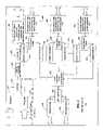
- FIG. 3is a functional block diagram illustrating an exemplary data service hub of the present invention.
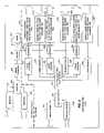
- FIG. 4is a functional block diagram illustrating an exemplary outdoor laser transceiver node according to the present invention.
- FIG. 5is a functional block diagram illustrating an optical tap connected to a subscriber interface by a single optical waveguide according to one exemplary embodiment of the present invention.
- FIG. 6is a functional block diagram illustrating an exemplary data service hub according to an alternative exemplary embodiment of the present invention where upstream optical signals and downstream optical signals are propagated along separate optical waveguides.
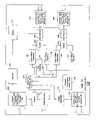
- FIG. 7is a functional block diagram illustrating an exemplary outdoor laser transceiver node that can accept upstream and downstream optical signals that are propagated along separate optical waveguides in addition to unidirectional signals that can be mixed with the downstream optical signals.
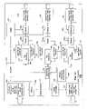
- FIG. 8is a functional block diagram illustrating yet another exemplary outdoor laser transceiver node that can accept optical signals propagating in separate upstream and downstream optical waveguides in addition to multiple optical waveguides that propagate unidirectional signals.
- FIG. 9is a functional block diagram illustrating another exemplary embodiment of a data service hub in which unidirectional signals such as video or RF signals are combined with downstream optical signals.
- FIG. 10is a functional block diagram illustrating another exemplary outdoor laser transceiver node that can process a combined downstream signal that comprises downstream optical signals in addition to unidirectional signals like RF transmissions or video data.
- FIG. 11is a functional block diagram illustrating another exemplary outdoor laser transceiver node that employs dual transceivers between tap multiplexers and respective groups of subscribers.
- FIG. 12is a functional block diagram illustrating another exemplary outdoor laser transceiver node that includes optical taps disposed within the laser transceiver node itself.
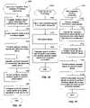
- FIG. 13is a logic flow diagram illustrating an exemplary method for processing unidirectional and bidirectional optical signals with a laser transceiver node of the present invention.
- FIG. 14is a logic flow diagram illustrating an exemplary process for handling downstream optical signals with a laser transceiver node according to the present invention.
- FIG. 15is a logic flow diagram illustrating an exemplary process for handling upstream optical signals with an exemplary laser transceiver node according to the present invention.
- FIG. 16is a logic flow diagram illustrating the processing of unidirectional and bidirectional optical signals with an optical tap according to the present invention.
- FIG. 17is a logic flow diagram illustrating the processing of unidirectional optical signals and bidirectional optical signals with a subscriber interface according to the present invention.
- the present inventionmay be embodied in hardware or software or a combination thereof disposed within an optical network.
- the present inventioncan comprise a laser transceiver node disposed between a data service hub and a subscriber that can allocate additional or reduced bandwidth based upon the demand of one or more subscribers.
- the present inventioncan support one gigabit or faster Ethernet communications in optical form to and from the data service hub and partition or apportion this optical bandwidth into distribution groups of a predetermined number.
- the present inventionallows bandwidth to be offered to subscribers in preassigned increments. The flexibility and diversity of the present invention can be attributed to a few components.
- the laser transceiver node of the present inventioncan comprise an optical tap routing device that is coupled to one or more tap multiplexers.
- the optical tap routing devicecan assign multiple subscribers to a single port that receives downstream optical signals from a data service hub.
- the laser transceiver node of the present inventioncan comprise off-the-shelf hardware to generate optical signals.
- the laser transceiver node of the present inventioncan comprise one or more Fabry-Perot (F-P) lasers, distributed feedback lasers, or Vertical Cavity Surface Emitting Lasers (VCSELs) in the transmitters.
- F-PFabry-Perot
- VCSELsVertical Cavity Surface Emitting Lasers
- the present inventioncan also comprise efficient couplers, such as optical taps, between the laser transceiver node and a respective subscriber optical interface.
- the optical tapcan divide optical signals among a plurality of subscribers and can be simple in its design.
- the optical tapcan connect to a limited number of optical waveguides at a point remote from the laser transceiver node so that high concentrations of optical waveguides at the laser transceiver node can be avoided.
- the optical tapcan be disposed within the laser transceiver node of the present invention.
- FIG. 1is a functional block diagram illustrating an exemplary optical network architecture 100 according to the present invention.
- the exemplary optical network architecture 100comprises a data service hub 110 that is connected to outdoor laser transceiver nodes 120 .
- the laser transceiver nodes 120are connected to an optical taps 130 .
- the optical taps 130can be connected to a plurality of subscriber optical interfaces 140 .
- Between respective components of the exemplary optical network architecture 100are optical waveguides such as optical waveguides 150 , 160 , 170 , and 180 .
- the optical waveguides 150 - 180are illustrated by arrows where the arrowheads of the arrows illustrate exemplary directions of data flow between respective components of the illustrative and exemplary optical network architecture 100 .
- FIG. 1While only an individual laser transceiver node 120 , an individual optical tap 130 , and an individual subscriber optical interface 140 are illustrated in FIG. 1 , as will become apparent from FIG. 2 and its corresponding description, a plurality of laser transceiver nodes 120 , optical taps 130 , and subscriber optical interfaces 140 can be employed without departing from the scope and spirit of the present invention. Typically, in many of the exemplary embodiments of the present invention, multiple subscriber optical interfaces 140 are connected to one or more optical taps 130 .
- the outdoor laser transceiver node 120can allocate additional or reduced bandwidth based upon the demand of one or more subscribers that use the subscriber optical interfaces 140 .
- the outdoor laser transceiver node 120can be designed to withstand outdoor environmental conditions and can be designed to hang on a strand or fit in a pedestal or “hard hole.”
- the outdoor laser transceiver nodecan operate in a temperature range between minus 40 degrees Celsius to plus 60 degrees Celsius.
- the laser transceiver node 120can operate in this temperature range by using passive cooling devices that do not consume power.
- the outdoor laser transceiver node 120does not require active cooling and heating devices that control the temperature surrounding the laser transceiver node 120 .
- the present inventionattempts to place more of the decision-making electronics at the data service hub 110 instead of the laser transceiver node 120 .
- the decision-making electronicsare larger in size and produce more heat than the electronics placed in the laser transceiver node of the present invention.
- the laser transceiver node 120does not require active temperature controlling devices, the laser transceiver node 120 lends itself to a compact electronic packaging volume that is typically smaller than the environmental enclosures of conventional routers. Further details of the components that make up the laser transceiver node 120 will be discussed in further detail below with respect to FIGS. 4 , 7 , 8 , 10 , 11 , and 12 .
- three trunk optical waveguides 160 , 170 , and 180can conduct optical signals from the data service hub 110 to the outdoor laser transceiver node 120 .
- optical waveguideused in the present application can apply to optical fibers, planar light guide circuits, and fiber optic pigtails and other like optical waveguides.
- a first optical waveguide 160can carry broadcast video and other signals.
- the signalscan be carried in a traditional cable television format wherein the broadcast signals are modulated onto carriers, which in turn, modulate an optical transmitter (not shown) in the data service hub 110 .
- a second optical waveguide 170can carry downstream targeted services such as data and telephone services to be delivered to one or more subscriber optical interfaces 140 .
- the second optical waveguide 170can also propagate internet protocol broadcast packets, as is understood by those skilled in the art.
- a third optical waveguide 180can transport data signals upstream from the outdoor laser transceiver node 120 to the data service hub 110 .
- the optical signals propagated along the third optical waveguide 180can also comprise data and telephone services received from one or more subscribers. Similar to the second optical waveguide 170 , the third optical waveguide 180 can also carry IP broadcast packets, as is understood by those skilled in the art.
- the third or upstream optical waveguide 180is illustrated with dashed lines to indicate that it is merely an option or part of one exemplary embodiment according to the present invention. In other words, the third optical waveguide 180 can be removed.
- the second optical waveguide 170propagates optical signals in both the upstream and downstream directions as is illustrated by the double arrows depicting the second optical waveguide 170 . In such an exemplary embodiment where the second optical waveguide 170 propagates bidirectional optical signals, only two optical waveguides 160 , 170 would be needed to support the optical signals propagating between the data server's hub 110 in the outdoor laser transceiver node 120 .
- a single optical waveguidecan be the only link between the data service hub 110 and the laser transceiver node 120 .
- three different wavelengthscan be used for the upstream and downstream signals.
- bi-directional datacould be modulated on one wavelength.
- the optical tap 130can comprise an 8-way optical splitter. This means that the optical tap 130 comprising an 8-way optical splitter can divide downstream optical signals eight ways to serve eight different subscriber optical interfaces 140 . In the upstream direction, the optical tap 130 can combine the optical signals received from the eight subscriber optical interfaces 140 .
- the optical tap 130can comprise a 4-way splitter to service four subscriber optical interfaces 140 .
- the optical tap 130can further comprise a 4-way splitter that is also a pass-through tap meaning that a portion of the optical signal received at the optical tap 130 can be extracted to serve the 4-way splitter contained therein while the remaining optical energy is propagated further downstream to another optical tap or another subscriber optical interface 140 .
- the present inventionis not limited to 4-way and 8-way optical splitters. Other optical taps having fewer or more than 4-way or 8-way splits are not beyond the scope of the present invention.
- FIG. 2is a functional block diagram illustrating an exemplary optical network architecture 100 that further includes subscriber groupings 200 that correspond with a respective outdoor laser transceiver node 120 .
- FIG. 2illustrates the diversity of the exemplary optical network architecture 100 where a number of optical waveguides 150 connected between the outdoor laser transceiver node 120 and the optical taps 130 is minimized.
- FIG. 2also illustrates the diversity of subscriber groupings 200 that can be achieved with the optical tap 130 .
- Each optical tap 130can comprise an optical splitter.
- the optical tap 130allows multiple subscriber optical interfaces 140 to be coupled to a single optical waveguide 150 that is connected to the outdoor laser transceiver node 120 .
- six optical fibers 150are designed to be connected to the outdoor laser transceiver node 120 .
- sixteen subscriberscan be assigned to each of the six optical fibers 150 that are connected to the outdoor laser transceiver node 120 .
- twelve optical fibers 150can be connected to the outdoor laser transceiver node 120 while eight subscriber optical interfaces 140 are assigned to each of the twelve optical fibers 150 .
- the number of subscriber optical interfaces 140 assigned to a particular waveguide 150 that is connected between the outdoor laser transceiver node 120 and a subscriber optical interface 140can be varied or changed without departing from the scope and spirit of the present invention. Further, those skilled in the art recognize that the actual number of subscriber optical interfaces 140 assigned to the particular fiber optic cable is dependent upon the amount of power available on a particular optical fiber 150 .
- optical tap 130 Acan connect subscriber optical interfaces 140 A1 through subscriber optical interface 140 AN to the outdoor laser transmitter node 120
- optical tap 130 Acan also connect other optical taps 130 such as optical tap 130 AN to the laser transceiver node 120 .
- the combinations of optical taps 130 with other optical taps 130 in addition to combinations of optical taps 130 with subscriber optical interfaces 140are limitless.
- concentrations of distribution optical waveguides 150 at the laser transceiver node 120can be reduced. Additionally, the total amount of fiber needed to service a subscriber grouping 200 can also be reduced.
- the distance between the laser transceiver node 120 and the data service hub 110can comprise a range between 0 and 80 kilometers.
- the present inventionis not limited to this range. Those skilled in the art will appreciate that this range can be expanded by selecting various off-the-shelf components that make up several of the devices of the present system.
- optical waveguides disposed between the data service hub 110 and outdoor laser transceiver node 120are not beyond the scope of the present invention. Because of the bi-directional capability of optical waveguides, variations in the number and directional flow of the optical waveguides disposed between the data service hub 110 and the outdoor laser transceiver node 120 can be made without departing from the scope and spirit of the present invention.
- this functional block diagramillustrates an exemplary data service hub 110 of the present invention.
- the exemplary data service hub 110 illustrated in FIG. 3is designed for a two trunk optical waveguide system. That is, this data service hub 110 of FIG. 3 is designed to send and receive optical signals to and from the outdoor laser transceiver node 120 along the first optical waveguide 160 and the second optical waveguide 170 .
- the second optical waveguide 170supports bi-directional data flow. In this way, the third optical waveguide 180 discussed above is not needed.
- the data service hub 110can comprise one or more modulators 310 , 315 that are designed to support television broadcast services.
- the one or more modulators 310 , 315can be analog or digital type modulators. In one exemplary embodiment, there can be at least 78 modulators present in the data service hub 110 .
- modulators 310 , 315can be varied without departing from the scope and spirit of the present invention.
- the signals from the modulators 310 , 315are combined in a combiner 320 where they are supplied to an optical transmitter 325 where the radio frequency signals generated by the modulators 310 , 315 are converted into optical form.
- the optical transmitter 325can comprise one of Fabry-Perot (F-P) Laser Transmitters, distributed feedback lasers (DFBs), or Vertical Cavity Surface Emitting Lasers (VCSELs).
- F-PFabry-Perot
- DFBsdistributed feedback lasers
- VCSELsVertical Cavity Surface Emitting Lasers
- other types of optical transmittersare possible and are not beyond the scope of the present invention.
- the data service hub 110lends itself to efficient upgrading by using off-the-shelf hardware to generate optical signals.
- the optical signals generated by the optical transmitterare propagated to amplifier 330 such as an Erbium Doped Fiber Amplifier (EDFA) where the unidirectional optical signals are amplified.
- amplifier 330such as an Erbium Doped Fiber Amplifier (EDFA) where the unidirectional optical signals are amplified.
- EDFAErbium Doped Fiber Amplifier
- the amplified unidirectional optical signalsare then propagated out of the data service hub 110 via a unidirectional signal output port 335 which is connected to one or more first optical waveguides 160 .
- the unidirectional signal output port 335is connected to one or more first optical waveguides 160 that support unidirectional optical signals originating from the data service hub 110 to a respective laser transceiver node 120 .
- the data service hub 110 illustrated in FIG. 3can further comprise an Internet router 340 .
- the data service hub 110can further comprise a telephone switch 345 that supports telephony service to the subscribers of the optical network system 100 .
- other telephony servicesuch as Internet Protocol telephony can be supported by the data service hub 110 . If only Internet Protocol telephony is supported by the data service hub 110 , then it is apparent to those skilled in the art that the telephone switch 345 could be eliminated in favor of lower cost VoIP equipment.
- the telephone switch 345could be substituted with other telephone interface devices such as a soft switch and gateway. But if the telephone switch 345 is needed, it may be located remotely from the data service hub 110 and can be connected through any of several conventional means of interconnection.
- the data service hub 110can further comprise a logic interface 350 that is connected to a laser transceiver node routing device 355 .
- the logic interface 350can comprise a Voice over Internet Protocol (VoIP) gateway when required to support such a service.
- VoIPVoice over Internet Protocol
- the laser transceiver node routing device 355can comprise a conventional router that supports an interface protocol for communicating with one or more laser transceiver nodes 120 .
- This interface protocolcan comprise one of gigabit or faster Ethernet, Internet Protocol (IP) or SONET protocols.
- IPInternet Protocol
- SONETSONET protocols
- the logic interface 350 and laser transceiver node routing device 355can read packet headers originating from the laser transceiver nodes 120 and the internet router 340 .
- the logic interface 350can also translate interfaces with the telephone switch 345 . After reading the packet headers, the logic interface 350 and laser transceiver node routing device 355 can determine where to send the packets of information.
- the laser transceiver node routing device 355can supply downstream data signals to respective optical transmitters 325 .
- the data signals converted by the optical transmitters 325can then be propagated to a bi-directional splitter 360 .
- the optical signals sent from the optical transmitter 325 into the bi-directional splitter 360can then be propagated towards a bi-directional data input/output port 365 that is connected to a second optical waveguide 170 that supports bi-directional optical data signals between the data service hub 110 and a respective laser transceiver node 120 .
- Upstream optical signals received from a respective laser transceiver node 120can be fed into the bi-directional data input/output port 365 where the optical signals are then forwarded to the bi-directional splitter 360 .
- respective optical receivers 370can convert the upstream optical signals into the electrical domain.
- the upstream electrical signals generated by respective optical receivers 370are then fed into the laser transceiver node routing device 355 .
- Each optical receiver 370can comprise one or more photoreceptors or photodiodes that convert optical signals into electrical signals.
- the optical transmitters 325can propagate optical signals at 1310 nm. But where distances between the data service hub 110 and the laser transceiver node are more extreme, the optical transmitters 325 can propagate the optical signals at wavelengths of 1550 mm with or without appropriate amplification devices.
- optical transmitters 325 for each circuitmay be optimized for the optical path lengths needed between the data service hub 110 and the outdoor laser transceiver node 120 .
- the wavelengths discussedare practical but are only illustrative in nature. In some scenarios, it may be possible to use communication windows at 1310 and 1550 nm in different ways without departing from the scope and spirit of the present invention. Further, the present invention is not limited to a 1310 and 1550 nm wavelength regions. Those skilled in the art will appreciate that smaller or larger wavelengths for the optical signals are not beyond the scope and spirit of the present invention.
- the laser transceiver node 120can comprise a unidirectional optical signal input port 405 that can receive optical signals propagated from the data service hub 110 that are propagated along a first optical waveguide 160 .
- the optical signals received at the unidirectional optical signal input port 405can comprise broadcast video data.
- the optical signals received at the input port 405are propagated to an amplifier 410 such as an Erbium Doped Fiber Amplifier (EDFA) in which the optical signals are amplified.
- EDFAErbium Doped Fiber Amplifier
- the amplified optical signalsare then propagated to a splitter 415 that divides the broadcast video optical signals among diplexers 420 that are designed to forward optical signals to predetermined subscriber groups 200 .
- EDFAErbium Doped Fiber Amplifier
- the laser transceiver node 120can further comprise a bi-directional optical signal input/output port 425 that connects the laser transceiver node 120 to a second optical waveguide 170 that supports bi-directional data flow between the data service hub 110 and laser transceiver node 120 .
- Downstream optical signalsflow through the bi-directional optical signal input/output port 425 to an optical waveguide transceiver 430 that converts downstream optical signals into the electrical domain.
- the optical waveguide transceiverfurther converts upstream electrical signals into the optical domain.
- the optical waveguide transceiver 430can comprise an optical/electrical converter and an electrical/optical converter.
- Downstream and upstream electrical signalsare communicated between the optical waveguide transceiver 430 and an optical tap routing device 435 .
- the optical tap routing device 435can manage the interface with the data service hub optical signals and can route or divide or apportion the data service hub signals according to individual tap multiplexers 440 that communicate optical signals with one or more optical taps 130 and ultimately one or more subscriber optical interfaces 140 . It is noted that tap multiplexers 440 operate in the electrical domain to modulate laser transmitters in order to generate optical signals that are assigned to groups of subscribers coupled to one or more optical taps.
- Optical tap routing device 435is notified of available upstream data packets as they arrive, by each tap multiplexer 440 .
- the optical tap routing deviceis connected to each tap multiplexer 440 to receive these upstream data packets.
- the optical tap routing device 435relays the packets to the data service hub 110 via the optical waveguide transceiver 430 .
- the optical tap routing device 435can build a lookup table from these upstream data packets coming to it from all tap multiplexers 440 (or ports), by reading the source IP address of each packet, and associating it with the tap multiplexer 440 through which it came. This lookup table can then used to route packets in the downstream path.
- the optical tap routing devicelooks at the destination IP address (which is the same as the source IP address for the upstream packets). From the lookup table the optical tap routing device can determine which port is connected to that IP address, so it sends the packet to that port. This can be described as a normal layer 3 router function as is understood by those skilled in the art.
- the optical tap routing device 435can assign multiple subscribers to a single port. More specifically, the optical tap routing device 435 can service groups of subscribers with corresponding respective, single ports.
- the optical taps 130 coupled to respective tap multiplexers 440can supply downstream optical signals to pre-assigned groups of subscribers who receive the downstream optical signals with the subscriber optical interfaces 140 .
- the optical tap routing device 435can determine which tap multiplexers 440 is to receive a downstream electrical signal, or identify which of a plurality of optical taps 130 propagated an upstream optical signal (that is converted to an electrical signal).
- the optical tap routing device 435can format data and implement the protocol required to send and receive data from each individual subscriber connected to a respective optical tap 130 .
- the optical tap routing device 435can comprise a computer or a hardwired apparatus that executes a program defining a protocol for communications with groups of subscribers assigned to individual ports.
- One exemplary embodiment of the program defining the protocolis discussed in copending and commonly assigned provisional patent application entitled, “Protocol to Provide Voice and Data Services via Fiber Optic Cable,” filed on Oct. 27, 2000 and assigned U.S. Application Ser. No.
- the single ports of the optical tap routing deviceare connected to respective tap multiplexers 440 .
- the laser transceiver node 120can adjust a subscriber's bandwidth on a subscription basis or on an as-needed or demand basis.
- the laser transceiver node 120 via the optical tap routing device 435can offer data bandwidth to subscribers in pre-assigned increments.
- the laser transceiver node 120 via the optical tap routing device 435can offer a particular subscriber or groups of subscribers bandwidth in units of 1, 2, 5, 10, 20, 50, 100, 200, and 450 Megabits per second (Mb/s).
- Mb/sMegabits per second
- Each tap multiplexer 440propagate optical signals to and from various groupings of subscribers.
- Each tap multiplexer 440is connected to a respective optical transmitter 325 .
- each optical transmitter 325can comprise one of a Fabry-Perot (F-P) laser, a distributed feedback laser (DFB), or a Vertical Cavity Surface Emitting Laser (VCSEL).
- the optical transmittersproduce the downstream optical signals that are propagated towards the subscriber optical interfaces 140 .
- Each tap multiplexer 440is also coupled to an optical receiver 370 .
- Each optical receiver 370can comprise photoreceptors or photodiodes. Since the optical transmitters 325 and optical receivers 370 can comprise off-the-shelf hardware to generate and receive respective optical signals, the laser transceiver node 120 lends itself to efficient upgrading and maintenance to provide significantly increased data rates.
- Each optical transmitter 325 and each optical receiver 370are connected to a respective bi-directional splitter 360 .
- Each bi-directional splitter 360in turn is connected to a diplexer 420 which combines the unidirectional optical signals received from the splitter 415 with the downstream optical signals received from respective optical receivers 370 .
- broadcast video services as well as data servicescan be supplied with a single optical waveguide such as a distribution optical waveguide 150 as illustrated in FIG. 2 .
- optical signalscan be coupled from each respective diplexer 420 to a combined signal input/output port 445 that is connected to a respective distribution optical waveguide 150 .
- the laser transceiver node 120does not employ a conventional router.
- the components of the laser transceiver node 120can be disposed within a compact electronic packaging volume.
- the laser transceiver node 120can be designed to hang on a strand or fit in a pedestal similar to conventional cable TV equipment that is placed within the “last,” mile or subscriber proximate portions of a network. It is noted that the term, “last mile,” is a generic term often used to describe the last portion of an optical network that connects to subscribers.
- the optical tap routing device 435is not a conventional router, it does not require active temperature controlling devices to maintain the operating environment at a specific temperature.
- the laser transceiver node 120can operate in a temperature range between minus 40 degrees Celsius to 60 degrees Celsius in one exemplary embodiment.
- the laser transceiver node 120does not comprise active temperature controlling devices that consume power to maintain temperature of the laser transceiver node 120 at a single temperature
- the laser transceiver node 120can comprise one or more passive temperature controlling devices 450 that do not consume power.
- the passive temperature controlling devices 450can comprise one or more heat sinks or heat pipes that remove heat from the laser transceiver node 120 .
- the present inventionis not limited to these exemplary passive temperature controlling devices.
- the laser transceiver node 120can also provide high speed symmetrical data transmissions. In other words, the laser transceiver node 120 can propagate the same bit rates downstream and upstream to and from a network subscriber. This is yet another advantage over conventional networks, which typically cannot support symmetrical data transmissions as discussed in the background section above. Further, the laser transceiver node 120 can also serve a large number of subscribers while reducing the number of connections at both the data service hub 110 and the laser transceiver node 120 itself.
- the laser transceiver node 120also lends itself to efficient upgrading that can be performed entirely on the network side or data service hub 110 side. That is, upgrades to the hardware forming the laser transceiver node 120 can take place in locations between and within the data service hub 110 and the laser transceiver node 120 . This means that the subscriber side of the network (from distribution optical waveguides 150 to the subscriber optical interfaces 140 ) can be left entirely in-tact during an upgrade to the laser transceiver node 120 or data service hub 110 or both.
- the data communications path between the laser transceiver node 120 and the data service hub 110can operate at 1 Gb/s.
- the data path to subscriberscan support up to 2.7 Gb/s
- the data path to the networkcan only support 1 Gb/s. This means that not all of the subscriber bandwidth is useable. This is not normally a problem due to the statistical nature of bandwidth usage.
- An upgradecould be to increase the 1 Gb/s data path speed between the laser transceiver node 120 and the data service hub 110 . This may be done by adding more 1 Gb/s data paths. Adding one more path would increase the data rate to 2 Gb/s, approaching the total subscriber-side data rate. A third data path would allow the network-side data rate to exceed the subscriber-side data rate. In other exemplary embodiments, the data rate on one link could rise from 1 Gb/s to 2 Gb/s then to 10 Gb/s, so when this happens, a link can be upgraded without adding more optical links.
- the additional data pathsmay be achieved by any of the methods known to those skilled in the art. It may be accomplished by using a plurality of optical waveguide transceivers 430 operating over a plurality of optical waveguides, or they can operate over one optical waveguide at a plurality of wavelengths, or it may be that higher speed optical waveguide transceivers 430 could be used as shown above.
- a system upgradeis effected without having to make changes at the subscribers' premises.
- FIG. 5this Figure is a functional block diagram illustrating an optical tap 130 connected to a subscriber optical interface 140 by a single optical waveguide 150 according to one exemplary embodiment of the present invention.
- the optical tap 130can comprise a combined signal input/output port that is connected to another distribution optical waveguide that is connected to a laser transceiver node 120 .
- the optical tap 130can comprise an optical splitter 510 that can be a 4-way or 8-way optical splitter. Other optical taps having fewer or more than 4-way or 8-way splits are not beyond the scope of the present invention.
- the optical tapcan divide downstream optical signals to serve respective subscriber optical interfaces 140 .
- optical tap 130comprises a 4-way optical tap
- such an optical tapcan be of the pass-through type, meaning that a portion of the downstream optical signals is extracted or divided to serve a 4-way splitter contained therein, while the rest of the optical energy is passed further downstream to other distribution optical waveguides 150 .
- the optical tap 130is an efficient coupler that can communicate optical signals between the laser transceiver node 120 and a respective subscriber optical interface 140 .
- Optical taps 130can be cascaded, or they can be connected in a star architecture from the laser transceiver node 120 . As discussed above, the optical tap 130 can also route signals to other optical taps that are downstream relative to a respective optical tap 130 .
- the optical tap 130can also connect to a limited or small number of optical waveguides so that high concentrations of optical waveguides are not present at any particular laser transceiver node 120 .
- the optical tapcan connect to a limited number of optical waveguides 150 at a point remote from the laser transceiver node 120 so that high concentrations of optical waveguides 150 at a laser transceiver node can be avoided.
- the optical tap 130can be incorporated within the laser transceiver node 120 as will be discussed in further detail below with respect to another exemplary embodiment of the laser transceiver node 120 as illustrated in FIG. 12 .
- the subscriber optical interface 140functions to convert downstream optical signals received from the optical tap 130 into the electrical domain that can be processed with appropriate communication devices.
- the subscriber optical interface 140further functions to convert upstream electrical signals into upstream optical signals that can be propagated along a distribution optical waveguide 150 to the optical tap 130 .
- the subscriber optical interface 140can comprise an optical diplexer 515 that divides the downstream optical signals received from the distribution optical waveguide 150 between a bi-directional optical signal splitter 520 and an analog optical receiver 525 .
- the optical diplexer 515can receive upstream optical signals generated by a digital optical transmitter 530 .
- the digital optical transmitter 530converts electrical binary/digital signals to optical form so that the optical signals can be transmitted back to the data service hub 110 .
- the digital optical receiver 540converts optical signals into electrical binary/digital signals so that the electrical signals can be handled by processor 550 .
- the present inventioncan propagate the optical signals at various wavelengths.
- the wavelength regions discussedare practical and are only illustrative of exemplary embodiments. Those skilled in the art will appreciate that other wavelengths that are either higher or lower than or between the 1310 and 1550 nm wavelength regions are not beyond the scope of the present invention.
- the analog optical receiver 525can convert the downstream broadcast optical video signals into modulated RF television signals that are propagated out of the modulated RF unidirectional signal output 535 .
- the modulated RF unidirectional signal output 535can feed to RF receivers such as television sets (not shown) or radios (not shown).
- the analog optical receiver 525can process analog modulated RF transmission as well as digitally modulated RF transmissions for digital TV applications.
- the bi-directional optical signal splitter 520can propagate combined optical signals in their respective directions. That is, downstream optical signals entering the bi-directional optical splitter 520 from the optical the optical diplexer 515 , are propagated to the digital optical receiver 540 . Upstream optical signals entering it from the digital optical transmitter 530 are sent to optical diplexer 515 and then to optical tap 130 .
- the bi-directional optical signal splitter 520is connected to a digital optical receiver 540 that converts downstream data optical signals into the electrical domain. Meanwhile the bi-directional optical signal splitter 520 is also connected to a digital optical transmitter 530 that converts upstream electrical signals into the optical domain.
- the digital optical receiver 540can comprise one or more photoreceptors or photodiodes that convert optical signals into the electrical domain.
- the digital optical transmittercan comprise one or more lasers such as the Fabry-Perot (F-P) Lasers, distributed feedback lasers, and Vertical Cavity Surface Emitting Lasers (VCSELs).
- F-PFabry-Perot
- VCSELsVertical Cavity Surface Emitting Lasers
- the digital optical receiver 540 and digital optical transmitter 530are connected to a processor 550 that selects data intended for the instant subscriber optical interface 140 based upon an embedded address.
- the data handled by the processor 550can comprise one or more of telephony and data services such as an Internet service.
- the processor 550is connected to a telephone input/output 555 that can comprise an analog interface.
- the processor 550is also connected to a data interface 560 that can provide a link to computer devices, set top boxes, ISDN phones, and other like devices.
- the data interface 560can comprise an interface to a Voice over Internet Protocol (VoIP) telephone or Ethernet telephone.
- the data interface 560can comprise one of Ethernet's (10BaseT, 100BaseT, Gigabit) interface, HPNA interface, a universal serial bus (USB) an IEEE1394 interface, an ADSL interface, and other like interfaces.
- this figureis a functional block diagram illustrating an exemplary data service hub 110 B according to an alternative exemplary embodiment of the present invention where upstream optical signals and downstream optical signals are propagated along separate optical waveguides such as the second optical waveguide 170 and the third optical waveguide 180 discussed above with respect to FIG. 1 .
- the second optical waveguide 170is designed to carry only downstream optical signals while the third optical waveguide 180 is designed to carry only upstream optical signals from the laser transceiver node 120 .
- the exemplary data service hub 110 Bfurther comprises a downstream optical signal output port 605 that is coupled to the second optical waveguide 170 .
- the data service hub 110 Bfurther comprises an upstream optical signal input port that is coupled to the third optical waveguide 180 .
- the exemplary data service hub 110 Bseparate optical waveguides 180 and 170 carry the respective upstream and downstream optical transmissions. With this exemplary embodiment, power can be conserved since additional components that were previously used to combine and separate the upstream and downstream optical signals are eliminated.
- This exemplary embodiment of the data service hub 110 Bcan further reduce distance limitations due to power loss and cross talk.
- at each end of an optical transmitterwhich is supplying a lot of optical power compared with the received power, can create interference at the receiver due to incomplete isolation between the upstream and downstream optical signal directions.
- this interferencecan be substantially reduced or eliminated.
- this Figureillustrates a functional block diagram of an exemplary outdoor laser transceiver node 120 B that can accept upstream and downstream optical signals that are propagated along separate optical waveguides in addition to unidirectional signals that can be mixed with downstream optical signals.
- the laser transceiver node 120 Bcan be coupled to the exemplary data service hub 110 B illustrated in FIG. 6 .
- the laser transceiver node 120 Bcan comprise a downstream optical signal input port 705 that is coupled to the second optical waveguide 170 as illustrated in FIG. 1 .
- the downstream optical signal input port 705is coupled to an optical receiver 710 that converts the downstream optical signals into the electrical domain.
- the optical receiver 710in turn, feeds the electrical signals to the optical tap routing device 435 .
- the laser transceiver node 120 B of FIG. 7can further comprise an optical transmitter 720 that converts electrical signals received from the optical tap routing device 435 into the optical domain.
- the optical signals generated by the optical transmitter 720are fed to an upstream optical signal output port 715 .
- the upstream optical signal output port 715is coupled to the third optical waveguide 180 as illustrated in FIG. 1 .
- the bi-directional splitter 360has been replaced with a second diplexer 420 2 .
- the optical transmitter 325generates optical signals of a wavelength that is higher than the upstream optical signals produced by a respective subscriber optical interface 140 .
- the optical transmitter 325can produce optical signals having wavelengths between 1410 and 1490 nm while the upstream optical signals remain at the 1310 nm wavelength region.
- wavelengths discussedare only illustrative in nature. In some scenarios, it may be possible to use communication windows at 1310 and 1550 nm in different ways without departing from the scope and spirit of the present invention. Further, the present invention is not limited to the wavelength regions discussed above. Those skilled in the art will appreciate that smaller or larger wavelengths for the optical signals are not beyond the scope and spirit of the present invention.
- the additional diplexer 420can be substituted for the previous bi-directional splitter 360 (illustrated in the exemplary embodiment of FIG. 4 ).
- the additional or substituted diplexer 420does not exhibit the same loss as the previous bi-directional splitter 360 that is used in the exemplary embodiment of FIG. 4 .
- This substitution of the bi-directional splitter 360 with the additional diplexer 420can also be applied to the subscriber optical interface 140 . That is, when the upstream and downstream optical signals are operating at respective different wavelength regions, the bidirectional optical signal splitter 520 of the subscriber optical interface 140 can be substituted with a diplexer 420 .
- the substitution of the bi-directional splitter 360 with the diplexer 420can reduce the optical loss between the laser transceiver node 120 and the subscriber optical interface 140 .
- the optical interface 140uses the bi-directional optical signal splitter 520 with a corresponding loss in optical power as illustrated in FIG. 5 .
- the components of the laser transceiver node 120can be made without departing from the scope and spirit of the present invention.
- this Figureillustrates another exemplary outdoor, laser transceiver node 120 C that can accept optical signals propagating from separate upstream and downstream optical waveguides in addition to multiple optical waveguides that propagate unidirectional signals.
- the laser transceiver node 120 C of FIG. 8can comprise multiple unidirectional signal input ports 805 that are coupled to a plurality of first optical waveguides 160 .
- the amplifier 410has been removed from the laser transceiver node 120 C as illustrated in FIG. 8 .
- the amplifier 410is taken out of the laser transceiver node 120 C and placed in the data service hub 110 .
- the optical signals propagating from the multiple first optical waveguides 160are combined with the upstream and downstream optical signals originating from the second set of diplexers 420 2 using the first set of diplexers 420 1 .
- This design to remove the amplifier 410 (that typically comprises an Erbium Doped Fiber Amplifier—EDFA) from the laser transceiver node 120 C of FIG. 8 to the data service hub 110 and to include multiple first optical waveguides 160 feeding into the laser transceiver node 120 C,may be made on the basis of economics and optical waveguide availability.
- EDFAErbium Doped Fiber Amplifier
- FIG. 9illustrates another exemplary embodiment of a data service hub 110 D in which unidirectional signals such as video or RF signals are combined with downstream optical signals.
- the data service hub 110 Dfurther comprises a splitter 415 that feeds the broadcast video optical signals to respective diplexers 420 .
- the respective diplexers 420combine the broadcast video optical signals with the downstream data optical signals produced by respective optical transmitters 325 .
- the first optical waveguide 160 as illustrated in FIG. 1can be eliminated since the broadcast video optical signals are combined with the downstream data optical signals along the second optical waveguide 170 .
- FIG. 10illustrates another exemplary laser transceiver node 120 D that can be coupled to the data service hub 110 D as illustrated in FIG. 9 .
- the laser transceiver node 120 Dcomprises a combined downstream optical signal input 1005 that is coupled to a second optical waveguide 160 that provides a combined downstream optical signal comprising broadcast video services and data service.
- the laser transceiver node 120 Dfurther comprises a diplexer 420 that feeds the broadcast video or RF signals to an amplifier 410 .
- the broadcast video or RF optical signalsare then sent to a splitter 415 which then sends the optical signals to the first set of diplexers 420 1 .
- the combination of the data service hub 110 D as illustrated in FIG. 9 and the laser transceiver node 120 D as illustrated in FIG. 10conserves optical waveguides between these two devices.
- a single fiber(not shown) to operatively link a data service hub 110 and a laser transceiver node 120 .
- different wavelengthscould be used to propagate upstream and downstream optical signals.
- FIG. 11is a functional block diagram illustrating another exemplary outdoor laser transceiver node 120 E that employs dual transceivers between tap multiplexers 440 and respective groups of subscribers.
- the downstream optical signals originating from each respective tap multiplexer 440are split immediately after the tap multiplexer 440 .
- each optical transmitter 325is designed to service only eight subscribers as opposed to sixteen subscribers of other embodiments. But each tap multiplexer 440 typically services sixteen or fewer subscribers.
- the splitting loss attributed to the optical taps 130can be substantially reduced.
- such embodimentsare designed to service sixteen or fewer subscribers with a corresponding theoretical splitting loss of approximately 14 dB (including an allowance for losses).
- the theoretical splitting lossis reduced to approximately 10.5 dB.
- the optical receivers 370cannot be paralleled because at all times one receiver 370 or the other is receiving signals from respective subscribers, while the other receiver 370 is not receiving signals.
- the receiver 370 not receiving any upstream optical signalscould output noise which would interfere with reception from the receiver 370 receiving upstream optical signals. Therefore, a switch 1105 can be employed to select the optical receiver 370 that is currently receiving an upstream optical signal.
- the tap multiplexercan control the switch 1105 since it knows which optical receiver 370 should be receiving upstream optical signals at any given moment of time.
- FIG. 12is a functional block diagram illustrating another exemplary outdoor laser transceiver node 120 F that includes optical taps 130 disposed within the laser transceiver node 120 F itself.
- optical waveguides 150 from each subscriber optical interface 140can be connected to the laser transceiver node 120 F.
- the number of optical waveguides 150 that are connected to the laser transceiver node 120 Fis such that two laser transceiver nodes 150 are needed to support the number of optical waveguides 150 .
- one laser transceiver node 120 Fcan be used to service the existing service base. When the service base expands to a number requiring an additional laser transceiver node 120 , the additional laser transceiver nodes can be added.
- two or more laser transceiver nodes 120 Fcan be co-located with one another for the reason discussed above.
- this exemplary embodimentenables two or more laser transceiver nodes 120 F to be placed in close proximity to one another.
- Such placement of laser transceiver nodes 120 Fcan conserve power and result in significant cost savings.
- future expansion of the optical architecture 100can easily be obtained. That is, one laser transceiver nodes 120 F can be installed until more subscribers join the optical network architecture 100 requiring the laser transceiver node.
- Optical waveguides 150can be connected to the co-located laser transceiver nodes as more subscribers join the optical network architecture 100 .
- FIG. 13this figure illustrates an exemplary method for processing unidirectional and bi-directional optical signals with a laser transceiver node 120 of the present invention.
- FIG. 13provides an overview of the processing performed by the laser transceiver node 120 .
- Step 1305is the first step in the exemplary laser transceiver node overview process 1300 .
- downstream RF modulated optical signalsare amplified by the amplifier 410 as illustrated in FIG. 4 .
- the amplifier 410can comprise an Erbium Doped Fiber Amplifier (EDFA).
- EDFAErbium Doped Fiber Amplifier
- other optical amplifiersare not beyond the scope of the present invention.
- bandwidth between respective subscriberscan be apportioned with the optical tap routing device 435 .
- the optical tap routing device 435can adjust a subscriber's bandwidth in accordance with a subscription or on an as-needed basis.
- the optical tap routing device 435can offer a particular subscriber or groups of subscribers bandwidth in units of 1, 2, 5, 10, 20, 50, 100, 200, and 450 Mb/s.
- Step 1310the downstream RF modulated optical signals are combined with the downstream optical signals originating from the tap multiplexers 440 .
- the combining of the downstream optical signalscan occur in diplexers 420 .
- Step 1315the combined downstream optical signals are propagated along the distribution optical waveguides 150 to respective assigned groups of optical taps 200 .
- upstream optical signalsare received by optical receivers 370 and then converted to upstream electrical signals.
- the upstream electrical signalsare sent to respective tap multiplexers 440 .
- Electrical signals received from respective tap multiplexers 440are combined in the optical tap routing device 435 according to Step 1325 .
- the upstream electrical signals from the optical tap routing device 435can be converted into the optical domain with either an optical waveguide transceiver 430 or an optical transmitter 720 .
- the upstream optical signalsare propagated towards the data service hub 110 via a bi-directional optical waveguide 170 or a dedicated upstream optical waveguide 180 .
- FIG. 14this figure illustrates a logic flow diagram of an exemplary process for handling downstream optical signals with a laser transceiver node 120 according to the present invention. More specifically, the logic flow diagram of FIG. 14 illustrates an exemplary method for communicating optical signals from a data service provider 110 to at least one subscriber.
- Step 1405is the first step in the exemplary process 1400 for communicating optical signals from a data service provider to at least one subscriber.
- downstream optical signalsare received at the laser transceiver node 120 .
- downstream optical signalscan be received at the unidirectional optical signal input port 405 as illustrated in FIG. 4 .
- downstream optical signalscan also be received at the bi-directional optical signal input/output port 425 also illustrated in FIG. 4 .
- the downstream optical signalscan be converted to the electrical domain.
- the downstream optical signals received at the bi-directional output signal input/output port 425can be converted into the electrical domain with an optical waveguide transceiver 430 .
- the optical waveguide transceiver 430can comprise an optical/electrical converter.
- the optical tap routing device 435can divide the converted electrical signals between tap multiplexers 440 that are assigned to groups of optical taps 130 .
- the downstream bandwidthcan be apportioned for subscribers with the optical tap routing device 435 .
- the optical tap routing device 435can apportion bandwidth to groups of subscribers based upon a subscription or based upon a current demand.
- the optical tap routing device 435can partition the bandwidth in units of 1, 2, 5, 10, 20, 50, 100, 200, and 450 Mb/s. However, the present invention is not limited to these increments. Other increments of bandwidth are not beyond the scope and spirit of the present invention.
- the optical tap routing device 435can apportion bandwidth in this way by executing a program defining a protocol for communications with groups of subscribers assigned to single ports. The single ports are connected to the respective tap multiplexers 440 .
- Step 1425the downstream electrical signals processed by the optical tap routing device 435 are multiplexed with the tap multiplexers 440 . Subsequently, in Step 1430 the downstream electrical signals can be converted into downstream optical signals with the optical transmitters 325 .
- the optical transmitters 325can comprise one of Fabry-Perot (F-P) lasers, distributed feedback lasers, and Vertical Cavity Surface Emitting Lasers (VCSELs).
- F-PFabry-Perot
- VCSELsVertical Cavity Surface Emitting Lasers
- other types of lasersare not beyond the scope of the present invention.
- Step 1435the unidirectional RF modulated optical signals received from the first optical waveguide 160 can be split into a plurality of paths with a splitter 415 .
- Step 1440the downstream paths of the RF modulated optical signals are combined with the paths of the downstream optical signals originating from the tap multiplexers 440 .
- FIG. 15illustrates a logic flow diagram of an exemplary process for handling upstream optical signals with an exemplary laser transceiver node 120 according to the present invention. More specifically, FIG. 15 illustrates a process for communicating optical signals from at least one subscriber to a data service provider hub.
- Step 1505is the first step in the exemplary laser transceiver node upstream process 1500 .
- upstream optical signals originating from subscribers to optical taps 130are propagated along distribution optical waveguides 150 .
- the upstream optical signalsare converted by a optical receiver 370 in Step 1510 .
- the upstream electrical signalsare combined at the optical tap routing device 435 .
- upstream bandwidth for subscribersis apportioned with the optical tap routing device 435 similar to how the downstream optical bandwidth is apportioned as discussed above with respect to FIG. 14 .
- the optical tap routing device 435can employ time division multiple access (TDMA) in order to service or support signals originating from multiple tap multiplexers 440 .
- TDMAtime division multiple access
- the optical tap routing device 435switches in time from one tap multiplexer 440 to another tap multiplexer 440 .
- TDMtime division multiplexing
- time division multiplexingoccurs when the optical tap routing device 435 sends data to multiple tap multiplexers 440 . In time division multiplexing, the signal is never removed, so receiving clocks remain synchronized.
- Step 1525the combined upstream electrical signals are converted to upstream optical signals with either the optical waveguide transceiver 430 or the optical transmitter 720 .
- Step 1530the combined upstream optical signals are propagated along an optical waveguide such as the second optical waveguide 170 or third optical waveguide 180 to the data service hub 110 .
- FIG. 16is a logic flow diagram illustrating the processing of unidirectional and bi-directional optical signals with an optical tap 130 according to the present invention.
- certain steps in the process described belowmust naturally proceed others for the present invention to function as described.
- the present inventionis not limited to the order of steps described if such order or sequence does not alter the functionality of the present invention. That is, it is recognized that some steps may be performed before or after other steps without departing from the scope and spirit of the present invention.
- Step 1605is the first step in the optical tap process 1600 .
- Step 1605diverts signals from an optical waveguide such as a distribution optical waveguide 150 coupled to a laser transceiver node to the combined signal input/output port 505 .
- downstream optical signals that were tappedare split with the optical splitter 510 .
- the optical splitter 510can split the downstream optical signals to one or more subscriber interfaces or other taps or splitters or combination thereof via distribution optical waveguides 150 .
- the downstream tap combined optical signalscan be propagated to and upstream optical signal from respective subscribers can be received and combined with the optical splitter 510 .
- FIG. 17is a logic flow diagram illustrating exemplary processing of unidirectional optical signals and bi-directional optical signals with a subscriber optical interface 140 according to the present invention.
- certain steps in the process described belowmust naturally proceed others for the present invention to function as described.
- the present inventionis not limited to the order of steps described if such order or sequence does not alter the functionality of the present invention. That is, it is recognized that some steps may be performed before or after other steps without departing from the scope and spirit of the present invention.
- Step 1705is the first step in the subscriber optical interface process 1700 .
- Step 1705combined downstream optical signals are received with an optical diplexer 515 .
- Step 1710the RF modulated downstream optical signals are separated from the downstream data optical signals originating from the tap multiplexers 440 .
- Step 1715the downstream RF modulated optical signals are converted to downstream electrical optical signals with an analog optical receiver 525 .
- the analog optical receiver 525can handle both analog modulated signals in addition to digitally modulated signals for digital TV applications.
- the upstream electrical signalsare converted to optical signals with the digital optical transmitter 530 .
- the digital optical transmitter 530can comprise one of a Fabry-Perot (F-P) laser, a distributed feedback (DFB) laser, and a vertical cavity surface emitting laser (VCSEL) or other similar lasers.
- the upstream electrical signalscan be generated from a telephone input/output port 555 or a data interface 560 or both (as discussed above).
- Step 1725downstream electrical signals emitted from the digital optical receiver 540 are received by a processor 550 .
- the processor 550propagates these electrical signals to appropriate output devices such as the telephone input/output port 555 or data interface 560 or both.
- the telephone input/output port 555 or the data interface 560 or bothcan generate upstream electrical signals that are sent to the processor 550 and then converted into the optical domain with the digital optical transmitter 530 .
- optical network architecture 100 of the present inventioncan provide at least one of video, telephone, and computer communication services via the optical signals.
- video layer comprising the RF modulated signalscan be removed from the exemplary optical network architecture 100 without departing from the scope and spirit of the present invention.
- an all fiber optical network and methodthat can propagate the same bit rate downstream and upstream to/from a network subscriber are provided. Further, the present invention provides an optical network system and method that can service a large number of subscribers while reducing the number of connections at the data service hub.
- the present inventionalso provides an active signal source that can be disposed between a data service hub and a subscriber and that can be designed to withstand outdoor environmental conditions.
- the present inventioncan also be designed to hang on a strand or fit in a pedestal similar to conventional cable TV equipment that is placed within a last mile of a communications network.
- the system and method of the present inventioncan receive at least one Gigabit or faster Ethernet communications in optical form from a data service hub and partition or apportion this optical bandwidth into distribution groups of a predetermined number.
- the system and method of the present inventioncan allocate additional or reduced bandwidth based upon the demand of one or more subscribers on an optical network.
- the optical network system of the present inventionlends itself to efficient upgrading that can be performed entirely on the network side. In other words, the optical network system allows upgrades to hardware to take place in locations between and within a data service hub and an active signal source disposed between the data service hub and a subscriber.
Landscapes
- Engineering & Computer Science (AREA)
- Computer Networks & Wireless Communication (AREA)
- Signal Processing (AREA)
- Optical Communication System (AREA)
Abstract
Description
Claims (20)
Priority Applications (2)
| Application Number | Priority Date | Filing Date | Title |
|---|---|---|---|
| US11/890,277US7599622B2 (en) | 2004-08-19 | 2007-08-03 | System and method for communicating optical signals between a data service provider and subscribers |
| US12/548,416US7953325B2 (en) | 2004-08-19 | 2009-08-26 | System and method for communicating optical signals between a data service provider and subscribers |
Applications Claiming Priority (2)
| Application Number | Priority Date | Filing Date | Title |
|---|---|---|---|
| US10/921,489US7269350B2 (en) | 2001-07-05 | 2004-08-19 | System and method for communicating optical signals between a data service provider and subscribers |
| US11/890,277US7599622B2 (en) | 2004-08-19 | 2007-08-03 | System and method for communicating optical signals between a data service provider and subscribers |
Related Parent Applications (1)
| Application Number | Title | Priority Date | Filing Date |
|---|---|---|---|
| US10/921,489ContinuationUS7269350B2 (en) | 2001-07-05 | 2004-08-19 | System and method for communicating optical signals between a data service provider and subscribers |
Related Child Applications (1)
| Application Number | Title | Priority Date | Filing Date |
|---|---|---|---|
| US12/548,416ContinuationUS7953325B2 (en) | 2004-08-19 | 2009-08-26 | System and method for communicating optical signals between a data service provider and subscribers |
Publications (2)
| Publication Number | Publication Date |
|---|---|
| US20080085117A1 US20080085117A1 (en) | 2008-04-10 |
| US7599622B2true US7599622B2 (en) | 2009-10-06 |
Family
ID=39275027
Family Applications (2)
| Application Number | Title | Priority Date | Filing Date |
|---|---|---|---|
| US11/890,277Expired - Fee RelatedUS7599622B2 (en) | 2004-08-19 | 2007-08-03 | System and method for communicating optical signals between a data service provider and subscribers |
| US12/548,416Expired - Fee RelatedUS7953325B2 (en) | 2004-08-19 | 2009-08-26 | System and method for communicating optical signals between a data service provider and subscribers |
Family Applications After (1)
| Application Number | Title | Priority Date | Filing Date |
|---|---|---|---|
| US12/548,416Expired - Fee RelatedUS7953325B2 (en) | 2004-08-19 | 2009-08-26 | System and method for communicating optical signals between a data service provider and subscribers |
Country Status (1)
| Country | Link |
|---|---|
| US (2) | US7599622B2 (en) |
Cited By (1)
| Publication number | Priority date | Publication date | Assignee | Title |
|---|---|---|---|---|
| US20200081215A1 (en)* | 2018-09-10 | 2020-03-12 | Arris Enterprises Llc | Node fiber connectorization |
Families Citing this family (5)
| Publication number | Priority date | Publication date | Assignee | Title |
|---|---|---|---|---|
| CN103631611A (en)* | 2012-08-23 | 2014-03-12 | 杭州海康威视数字技术股份有限公司 | Method and equipment for updating optical transmitter and receiver |
| TWI520510B (en)* | 2013-03-25 | 2016-02-01 | 傳承光電股份有限公司 | Optical transceiver |
| US10200123B2 (en) | 2016-06-20 | 2019-02-05 | Cable Television Laboratories, Inc. | System and methods for distribution of heterogeneous wavelength multiplexed signals over optical access network |
| US10397672B2 (en)* | 2016-06-20 | 2019-08-27 | Cable Television Laboratories, Inc. | Systems and methods for intelligent edge to edge optical system and wavelength provisioning |
| EP3291494B1 (en)* | 2016-08-31 | 2020-09-30 | Corning Optical Communications LLC | Distribution point unit to exchange communication data between a service provider and subscribers |
Citations (204)
| Publication number | Priority date | Publication date | Assignee | Title |
|---|---|---|---|---|
| US4253035A (en) | 1979-03-02 | 1981-02-24 | Bell Telephone Laboratories, Incorporated | High-speed, low-power, ITL compatible driver for a diode switch |
| US4295005A (en) | 1979-10-17 | 1981-10-13 | Western Electric Company, Inc. | Cable splice closure |
| US4495545A (en) | 1983-03-21 | 1985-01-22 | Northern Telecom Limited | Enclosure for electrical and electronic equipment with temperature equalization and control |
| US4500990A (en) | 1982-04-14 | 1985-02-19 | Nec Corporation | Data communication device including circuitry responsive to an overflow of an input packet buffer for causing a collision |
| US4654891A (en) | 1985-09-12 | 1987-03-31 | Clyde Smith | Optical communication of video information with distortion correction |
| US4655517A (en) | 1985-02-15 | 1987-04-07 | Crane Electronics, Inc. | Electrical connector |
| US4665517A (en) | 1983-12-30 | 1987-05-12 | International Business Machines Corporation | Method of coding to minimize delay at a communication node |
| US4733398A (en) | 1985-09-30 | 1988-03-22 | Kabushiki Kaisha Tohsiba | Apparatus for stabilizing the optical output power of a semiconductor laser |
| US4763317A (en) | 1985-12-13 | 1988-08-09 | American Telephone And Telegraph Company, At&T Bell Laboratories | Digital communication network architecture for providing universal information services |
| US4805979A (en) | 1987-09-04 | 1989-02-21 | Minnesota Mining And Manufacturing Company | Fiber optic cable splice closure |
| US4852023A (en) | 1987-05-12 | 1989-07-25 | Communications Satellite Corporation | Nonlinear random sequence generators |
| US4891694A (en) | 1988-11-21 | 1990-01-02 | Bell Communications Research, Inc. | Fiber optic cable television distribution system |
| US4945541A (en) | 1988-09-08 | 1990-07-31 | Digital Equipment Corporation | Method and apparatus for controlling the bias current of a laser diode |
| US4956863A (en) | 1989-04-17 | 1990-09-11 | Trw Inc. | Cryptographic method and apparatus for public key exchange with authentication |
| US4975899A (en) | 1987-01-05 | 1990-12-04 | British Telecommunications Public Limited Company | Optical broadcast network |
| US5105336A (en) | 1987-07-29 | 1992-04-14 | Lutron Electronics Co., Inc. | Modular multilevel electronic cabinet |
| US5132992A (en) | 1991-01-07 | 1992-07-21 | Paul Yurt | Audio and video transmission and receiving system |
| JPH04504433A (en) | 1989-01-23 | 1992-08-06 | グロガン,ジョージ、ウィルバー | Polymeric aqueous compositions for protective coatings |
| US5144267A (en) | 1989-12-06 | 1992-09-01 | Scientific-Atlanta, Inc. | Variable slope network for off-premises CATV system |
| US5179591A (en) | 1991-10-16 | 1993-01-12 | Motorola, Inc. | Method for algorithm independent cryptographic key management |
| US5189725A (en) | 1992-01-28 | 1993-02-23 | At&T Bell Laboratories | Optical fiber closure |
| US5247347A (en) | 1991-09-27 | 1993-09-21 | Bell Atlantic Network Services, Inc. | Pstn architecture for video-on-demand services |
| US5249194A (en) | 1991-03-14 | 1993-09-28 | Sumitomo Electric Industries, Ltd. | Laser diode protective circuit for an optical transmission apparatus |
| US5253250A (en) | 1991-12-31 | 1993-10-12 | Gte Laboratories Incorporated | Routing and switching of high-speed optical data with the header transmitted on a subcarrier frequency |
| US5253275A (en) | 1991-01-07 | 1993-10-12 | H. Lee Browne | Audio and video transmission and receiving system |
| US5303295A (en) | 1988-03-10 | 1994-04-12 | Scientific-Atlanta, Inc. | Enhanced versatility of a program control by a combination of technologies |
| US5313546A (en) | 1991-11-29 | 1994-05-17 | Sirti, S.P.A. | Hermetically sealed joint cover for fibre optic cables |
| US5325223A (en) | 1991-12-19 | 1994-06-28 | Northern Telecom Limited | Fiber optic telephone loop network |
| US5345504A (en) | 1988-03-10 | 1994-09-06 | Scientific-Atlanta, Inc. | Differential compensation control for off-premises CATV system |
| US5349457A (en) | 1991-12-19 | 1994-09-20 | Northern Telecom Limited | Fiber optic telephone loop network |
| US5365585A (en) | 1993-08-30 | 1994-11-15 | Motorola, Inc. | Method and apparatus for encryption having a feedback register with selectable taps |
| US5365588A (en) | 1993-03-12 | 1994-11-15 | Hughes Aircraft Company | High speed encryption system and method |
| US5378174A (en) | 1993-03-18 | 1995-01-03 | The Whitaker Corporation | Enclosure for variety of terminal blocks |
| US5402315A (en) | 1992-07-30 | 1995-03-28 | Reichle+De-Massari Ag | Printed circuit board and assembly module for connection of screened conductors for distribution boards and distribution systems in light-current systems engineering |
| CA2107922A1 (en) | 1993-10-07 | 1995-04-08 | Hung-Huei Liao | Adjustable reflection control device for fiber optics |
| US5412498A (en) | 1991-03-29 | 1995-05-02 | Raynet Corporation | Multi-RC time constant receiver |
| JPH0720327Y2 (en) | 1988-09-26 | 1995-05-15 | 富士重工業株式会社 | Engine decompression device |
| US5432875A (en) | 1993-02-19 | 1995-07-11 | Adc Telecommunications, Inc. | Fiber optic monitor module |
| US5469507A (en) | 1994-03-01 | 1995-11-21 | International Business Machines Corporation | Secure communication and computation in an insecure environment |
| US5495549A (en) | 1994-02-18 | 1996-02-27 | Keptel, Inc. | Optical fiber splice closure |
| US5509099A (en) | 1995-04-26 | 1996-04-16 | Antec Corp. | Optical fiber closure with sealed cable entry ports |
| US5510921A (en) | 1990-11-30 | 1996-04-23 | Hitachi, Ltd. | Optical frequency division multiplexing network |
| EP0713347A2 (en) | 1994-11-17 | 1996-05-22 | AT&T Corp. | Method and apparatus enabling STM and packet mode access on a broadband communications network |
| US5528582A (en) | 1994-07-29 | 1996-06-18 | At&T Corp. | Network apparatus and method for providing two way broadband communications |
| US5528455A (en) | 1995-04-26 | 1996-06-18 | Tektronix, Inc. | Modular instrument chassis |
| EP0720322A2 (en) | 1994-12-30 | 1996-07-03 | Alcatel N.V. | Optical access communications network |
| US5534912A (en) | 1994-04-26 | 1996-07-09 | Bell Atlantic Network Services, Inc. | Extended range video on demand distribution system |
| US5541917A (en) | 1994-09-12 | 1996-07-30 | Bell Atlantic | Video and TELCO network control functionality |
| US5557317A (en) | 1994-05-20 | 1996-09-17 | Nec Corporation | Video-on-demand system with program relocation center |
| US5559858A (en) | 1993-05-28 | 1996-09-24 | U S West Advanced Technologies, Inc. | Method and apparatus for delivering secured telephony service in a hydrid coaxial cable network |
| US5566099A (en) | 1993-10-06 | 1996-10-15 | Nec Corporation | Pseudorandom number generator |
| US5572348A (en) | 1995-02-09 | 1996-11-05 | Carlson; Jeffrey A. | Universal demarcation point |
| US5572349A (en) | 1993-12-15 | 1996-11-05 | British Telecommunications Public Limited Company | Communications system |
| US5572347A (en) | 1991-07-30 | 1996-11-05 | Alcatel Network Systems, Inc. | Switched video architecture for an optical fiber-to-the-curb telecommunications system |
| US5572328A (en) | 1994-04-27 | 1996-11-05 | Hewlett-Packard Company | Optical detector including Bragg waveguide structure |
| US5610744A (en) | 1995-02-16 | 1997-03-11 | Board Of Trustees Of The University Of Illinois | Optical communications and interconnection networks having opto-electronic switches and direct optical routers |
| US5666487A (en) | 1995-06-28 | 1997-09-09 | Bell Atlantic Network Services, Inc. | Network providing signals of different formats to a user by multplexing compressed broadband data with data of a different format into MPEG encoded data stream |
| US5694232A (en) | 1995-12-06 | 1997-12-02 | Ericsson Raynet | Full duplex optical modem for broadband access network |
| US5701186A (en) | 1993-06-04 | 1997-12-23 | Ciena Corporation | Optical cable TV system |
| US5706303A (en) | 1996-04-09 | 1998-01-06 | Lawrence; Zachary Andrew | Laser diode coupling and bias circuit and method |
| JPH1020123A (en) | 1996-07-05 | 1998-01-23 | Kokusai Electric Co Ltd | Optical attenuator |
| US5715020A (en) | 1993-08-13 | 1998-02-03 | Kabushiki Kaisha Toshiba | Remote control system in which a plurality of remote control units are managed by a single remote control device |
| US5731546A (en) | 1996-03-15 | 1998-03-24 | Molex Incorporated | Telecommunications cable management tray with a row of arcuate cable guide walls |
| USRE35774E (en) | 1991-09-10 | 1998-04-21 | Hybrid Networks, Inc. | Remote link adapter for use in TV broadcast data transmission system |
| US5769159A (en) | 1995-04-19 | 1998-06-23 | Daewoo Electronics Co., Ltd | Apparatus for opening/closing a radiating section by using a shape memory alloy |
| US5778017A (en) | 1993-03-19 | 1998-07-07 | Fujitsu Limited | Method and device for controlling a semiconductor laser |
| US5790523A (en) | 1993-09-17 | 1998-08-04 | Scientific-Atlanta, Inc. | Testing facility for a broadband communications system |
| US5793413A (en) | 1995-05-01 | 1998-08-11 | Bell Atlantic Network Services, Inc. | Wireless video distribution |
| US5793506A (en) | 1995-02-18 | 1998-08-11 | Alcatel N.V. | Optical transmission system for cable television signals and video and telecommunications signals |
| US5799088A (en) | 1993-12-01 | 1998-08-25 | Raike; William Michael | Non-deterministic public key encrypton system |
| US5802089A (en) | 1996-10-22 | 1998-09-01 | Maxim Integrated Products, Inc. | Laser diode driver having automatic power control with smooth enable function |
| US5822102A (en) | 1996-07-10 | 1998-10-13 | At&T Corp | Passive optical network employing upconverted 16-cap signals |
| US5861966A (en) | 1995-12-27 | 1999-01-19 | Nynex Science & Technology, Inc. | Broad band optical fiber telecommunications network |
| US5867485A (en) | 1996-06-14 | 1999-02-02 | Bellsouth Corporation | Low power microcellular wireless drop interactive network |
| US5875430A (en) | 1996-05-02 | 1999-02-23 | Technology Licensing Corporation | Smart commercial kitchen network |
| US5880864A (en) | 1996-05-30 | 1999-03-09 | Bell Atlantic Network Services, Inc. | Advanced optical fiber communications network |
| US5892865A (en) | 1997-06-17 | 1999-04-06 | Cable Television Laboratories, Inc. | Peak limiter for suppressing undesirable energy in a return path of a bidirectional cable network |
| US5953690A (en) | 1996-07-01 | 1999-09-14 | Pacific Fiberoptics, Inc. | Intelligent fiberoptic receivers and method of operating and manufacturing the same |
| US5969836A (en) | 1997-12-12 | 1999-10-19 | Alcatel Usa Sourcing, L.P. | Method and apparatus for simultaneous transmission of digital telephony and analog video over a single optic fiber using wave division multiplexing |
| US5974063A (en) | 1996-11-12 | 1999-10-26 | Nec Corporation | Method and apparatus for driving laser diode in which deterioration of extinction ratio is prevented |
| JPH11305052A (en) | 1998-04-22 | 1999-11-05 | Ando Electric Co Ltd | Optical fiber non-reflecting terminating device and manufacture thereof |
| EP0955739A2 (en) | 1998-05-08 | 1999-11-10 | Nec Corporation | Multiple access communication system, using a bidirectional cable network, capable of measuring and guaranteeing the service quality for each service supplied to a subscriber station |
| US6002692A (en) | 1996-12-30 | 1999-12-14 | Hyundai Electronics America | Line interface unit for adapting broad bandwidth network to lower bandwidth network fabric |
| US6002720A (en) | 1991-01-07 | 1999-12-14 | H. Lee Browne, D/B/A Greenwich Information Technologies Llc | Audio and video transmission and receiving system |
| US6041056A (en) | 1995-03-28 | 2000-03-21 | Bell Atlantic Network Services, Inc. | Full service network having distributed architecture |
| US6097515A (en) | 1995-12-07 | 2000-08-01 | Bell Atlantic Network Services, Inc. | Switchable optical network unit |
| US6097159A (en) | 1998-02-27 | 2000-08-01 | Sony Corporation | Drive circuit of light emitting element |
| US6151343A (en) | 1995-09-05 | 2000-11-21 | Heidelberger Druckmaschinen Ag | Method and apparatus for driving diode pumped solid-state lasers |
| US6167553A (en) | 1996-07-17 | 2000-12-26 | Ericsson Inc. | Spiral scrambling |
| US6198558B1 (en) | 1998-04-07 | 2001-03-06 | Nortel Networks Limited | Architecture repartitioning to simplify outside-plant component of fiber-based access system |
| USRE37125E1 (en) | 1995-02-09 | 2001-04-03 | Optical Solutions, Inc. | Universal demarcation point |
| US6215939B1 (en) | 1998-07-02 | 2001-04-10 | Preformed Line Products Company | Optical fiber splice case with integral cable clamp, buffer cable storage area and metered air valve |
| WO2001027940A2 (en) | 1999-09-21 | 2001-04-19 | Optical Solutions, Inc. | System and method for transmitting a plurality of voice, data and video signals over passive optical network |
| US6229701B1 (en) | 1999-07-26 | 2001-05-08 | Compal Electronics, Inc. | Portable computer with heat dissipating device |
| US6229788B1 (en) | 1998-05-27 | 2001-05-08 | Nortel Networks Limited | Method and apparatus for traffic shaping in a broadband fiber-based access system |
| US20010002195A1 (en) | 1998-08-19 | 2001-05-31 | Path 1 Network Technologies, Inc., California Corporation | Methods and apparatus for providing quality-of-service guarantees in computer networks |
| US20010002486A1 (en) | 1998-01-02 | 2001-05-31 | Cryptography Research, Inc. | Leak-resistant cryptographic method and apparatus |
| US20010002196A1 (en) | 1998-08-19 | 2001-05-31 | Path 1 Network Technologies, Inc., California Corporation | Methods and apparatus for providing quality of service guarantees in computer networks |
| US20010004362A1 (en) | 1999-12-15 | 2001-06-21 | Satoshi Kamiya | Packet switch and packet switching method |
| US6295148B1 (en) | 1997-10-21 | 2001-09-25 | Antec Corporation | Optical network for transmitting two-way multicast signals |
| US6300562B1 (en) | 1999-07-29 | 2001-10-09 | Avaya Technology Corp. | Self-sealing telecommunications enclosure |
| US20010030785A1 (en) | 2000-02-23 | 2001-10-18 | Pangrac David M. | System and method for distributing information via a communication network |
| US6330155B1 (en) | 2000-03-28 | 2001-12-11 | Qtera Corporation | Method and apparatus for temperature control of electrical devices mounted on circuit boards |
| US6336201B1 (en) | 1994-09-26 | 2002-01-01 | Adc Telecommunications, Inc. | Synchronization in a communications system with multicarrier telephony transport |
| US20020006197A1 (en) | 2000-05-09 | 2002-01-17 | Carroll Christopher Paul | Stream-cipher method and apparatus |
| US6342004B1 (en) | 2000-03-01 | 2002-01-29 | Digital Lightwave, Inc. | Automatic fire shutter mechanism for rack mounted chassis systems |
| US20020021465A1 (en) | 1999-12-30 | 2002-02-21 | Richard Moore | Home networking gateway |
| US20020027928A1 (en) | 2000-08-24 | 2002-03-07 | Fang Rong C. | Apparatus and method for facilitating data packet transportation |
| US6356369B1 (en) | 1999-02-22 | 2002-03-12 | Scientific-Atlanta, Inc. | Digital optical transmitter for processing externally generated information in the reverse path |
| US6360320B2 (en) | 1997-04-23 | 2002-03-19 | Sony Corporation | Information processing apparatus, information processing method, information processing system and recording medium using an apparatus id and provided license key for authentication of each information to be processed |
| US6362908B1 (en) | 1998-12-02 | 2002-03-26 | Marconi Communications, Inc. | Multi-service adaptable optical network unit |
| US20020039218A1 (en) | 2000-10-04 | 2002-04-04 | Wave7 Optics, Inc. | System and method for communicating optical signals between a data service provider and subscribers |
| US6385366B1 (en) | 2000-08-31 | 2002-05-07 | Jedai Broadband Networks Inc. | Fiber to the home office (FTTHO) architecture employing multiple wavelength bands as an overlay in an existing hybrid fiber coax (HFC) transmission system |
| US20020063924A1 (en) | 2000-03-02 | 2002-05-30 | Kimbrough Mahlon D. | Fiber to the home (FTTH) multimedia access system with reflection PON |
| US20020063932A1 (en) | 2000-05-30 | 2002-05-30 | Brian Unitt | Multiple access system for communications network |
| US20020080444A1 (en) | 2000-12-22 | 2002-06-27 | David Phillips | Multiple access system for communications network |
| US20020089725A1 (en) | 2000-10-04 | 2002-07-11 | Wave7 Optics, Inc. | System and method for communicating optical signals upstream and downstream between a data service provider and subscribers |
| US6424656B1 (en) | 1998-05-15 | 2002-07-23 | Alcatel | Method to assign upstream timeslots to a network terminal and medium access controller for performing such a method |
| US6427035B1 (en) | 1999-08-12 | 2002-07-30 | Bellsouth Intellectual Property Corporation | Method and apparatus for deploying fiber optic cable to subscriber |
| WO2002060123A2 (en) | 2000-10-26 | 2002-08-01 | Wave7 Optics, Inc. | Method and system for processing downstream packets of an optical network |
| WO2002030019A3 (en) | 2000-10-04 | 2002-08-01 | Wave7 Optics Inc | System and method for communicating optical signals between a data service provider and subscribers |
| US20020105965A1 (en) | 2000-09-22 | 2002-08-08 | Narad Networks, Inc. | Broadband system having routing identification based switching |
| US20020106178A1 (en) | 2000-12-22 | 2002-08-08 | Bumgarner Kirk P. | Fiber optic spools and methods of making the same |
| US6452714B1 (en) | 2000-07-20 | 2002-09-17 | Trw Inc. | Enhanced feed forward optical frequency/phase demodulator |
| US20020135843A1 (en) | 2001-03-20 | 2002-09-26 | Dumitru Gruia | Point-to-multipoint optical access network distributed with central office interface capacity |
| US6460182B1 (en) | 1999-05-11 | 2002-10-01 | Marconi Communications, Inc. | Optical communication system for transmitting RF signals downstream and bidirectional telephony signals which also include RF control signals upstream |
| US20020141159A1 (en) | 2001-03-29 | 2002-10-03 | Bloemen James Andrew | Sealed and passively cooled telecommunications customer service terminal |
| US6463068B1 (en) | 1997-12-31 | 2002-10-08 | Cisco Technologies, Inc. | Router with class of service mapping |
| US20020164026A1 (en) | 1999-02-11 | 2002-11-07 | Antti Huima | An authentication method |
| US6483635B1 (en) | 2000-06-07 | 2002-11-19 | Cirrex Corp. | Apparatus for light amplification |
| US6486907B1 (en) | 1997-01-07 | 2002-11-26 | Foxcom Ltd. | Satellite distributed television |
| US6490727B1 (en) | 1999-10-07 | 2002-12-03 | Harmonic, Inc. | Distributed termination system for two-way hybrid networks |
| US20020181925A1 (en) | 2001-05-21 | 2002-12-05 | Wave7 Optics, Inc. | Cable splice enclosure and components |
| US6493335B1 (en) | 1996-09-24 | 2002-12-10 | At&T Corp. | Method and system for providing low-cost high-speed data services |
| US6496641B1 (en) | 1999-08-12 | 2002-12-17 | Bellsouth Intellectual Property Corporation | Fiber optic interface device |
| US20030007220A1 (en) | 2001-07-05 | 2003-01-09 | Wave7 Optics, Inc. | System and method for communicating optical signals to multiple subscribers having various bandwidth demands connected to the same optical waveguide |
| US20030007210A1 (en) | 2001-07-05 | 2003-01-09 | Wave7 Optics, Inc. | System and method for increasing upstream communication efficiency in an optical network |
| US6507494B1 (en) | 2000-07-27 | 2003-01-14 | Adc Telecommunications, Inc. | Electronic equipment enclosure |
| WO2003005612A1 (en) | 2001-07-05 | 2003-01-16 | Wave7 Optics, Inc. | Methods and systems for providing return path for signals generated by legacy terminals in optical network |
| US6519280B1 (en) | 1999-03-02 | 2003-02-11 | Legerity, Inc. | Method and apparatus for inserting idle symbols |
| US6529301B1 (en) | 1999-07-29 | 2003-03-04 | Nortel Networks Limited | Optical switch and protocols for use therewith |
| WO2003021820A1 (en) | 2001-08-28 | 2003-03-13 | Wave7 Optics, Inc. | System and method for increasing upstream communication efficiency in an optical network |
| US20030048512A1 (en) | 2001-09-10 | 2003-03-13 | Takeshi Ota | Optical transceiver and transmission media converter |
| WO2003023980A2 (en) | 2001-09-10 | 2003-03-20 | Wave7 Optics, Inc. | System and method for securing a communication channel |
| US6546014B1 (en) | 2001-01-12 | 2003-04-08 | Alloptic, Inc. | Method and system for dynamic bandwidth allocation in an optical access network |
| US20030072059A1 (en) | 2001-07-05 | 2003-04-17 | Wave7 Optics, Inc. | System and method for securing a communication channel over an optical network |
| US20030090320A1 (en) | 2001-11-14 | 2003-05-15 | John Skrobko | Fiber-to the-home (FTTH) optical receiver having gain control and a remote enable |
| US6577414B1 (en) | 1998-02-20 | 2003-06-10 | Lucent Technologies Inc. | Subcarrier modulation fiber-to-the-home/curb (FTTH/C) access system providing broadband communications |
| US20030128983A1 (en) | 1999-05-11 | 2003-07-10 | Buabbud George H. | Digital RF return over fiber |
| US20030154282A1 (en) | 2001-03-29 | 2003-08-14 | Microsoft Corporation | Methods and apparatus for downloading and/or distributing information and/or software resources based on expected utility |
| US6611522B1 (en) | 1998-06-19 | 2003-08-26 | Juniper Networks, Inc. | Quality of service facility in a device for performing IP forwarding and ATM switching |
| US6621975B2 (en) | 2001-11-30 | 2003-09-16 | Corning Cable Systems Llc | Distribution terminal for network access point |
| WO2003079567A1 (en) | 2002-03-14 | 2003-09-25 | Wave7 Optics, Inc. | Method and system for providing a return path for signals generated by legacy terminals in an optical network |
| US20030189587A1 (en) | 1998-11-30 | 2003-10-09 | Microsoft Corporation | Interactive video programming methods |
| US20030194241A1 (en) | 2001-07-05 | 2003-10-16 | Wave7 Optics, Inc. | Method and system for providing a return data path for legacy terminals by using existing electrical waveguides of a structure |
| WO2003090396A2 (en) | 2002-04-17 | 2003-10-30 | Wave7 Optics, Inc. | Method and system for providing a return data path for legacy terminals by using existing electrical waveguides of a structure |
| US20030206564A1 (en) | 2000-09-28 | 2003-11-06 | Andrew Mills | Method and apparatus for handling link suspend pulse and silent line state transitions of a network device |
| US20030206634A1 (en) | 1997-10-24 | 2003-11-06 | Rose Gregory G. | Method and apparatus for generating encryption stream ciphers |
| US20030223750A1 (en) | 2001-07-05 | 2003-12-04 | Farmer James O. | Method and system for providing a return path for signals generated by legacy terminals in an optical network |
| US6680948B1 (en) | 1999-02-02 | 2004-01-20 | Tyco Telecommunications (Us) Inc. | System and method for transmitting packets over a long-haul optical network |
| US6682010B2 (en) | 2001-08-13 | 2004-01-27 | Dorsal Networks, Inc. | Optical fiber winding apparatus and method |
| US6687432B2 (en) | 1999-05-24 | 2004-02-03 | Broadband Royalty Corporation | Optical communication with predistortion to compensate for odd order distortion in modulation and travel |
| US6687376B1 (en) | 1998-12-29 | 2004-02-03 | Texas Instruments Incorporated | High-speed long code generation with arbitrary delay |
| US6707024B2 (en) | 1999-06-07 | 2004-03-16 | Fujitsu Limited | Bias circuit for a photodetector, and an optical receiver |
| US20040052527A1 (en) | 1999-03-18 | 2004-03-18 | Massachusetts Institute Of Technology | Hybrid electronic/optical switch system |
| US6738983B1 (en) | 1995-05-26 | 2004-05-18 | Irdeto Access, Inc. | Video pedestal network |
| US6740861B2 (en) | 2000-05-25 | 2004-05-25 | Matsushita Electric Industrial Co., Ltd | Photodetector and method having a conductive layer with etch susceptibility different from that of the semiconductor substrate |
| US20040131357A1 (en) | 2001-07-05 | 2004-07-08 | Wave7 Optics, Inc. | Method and system for supporting multiple services with a subscriber optical interface located outside a subscriber's premises |
| US20040141747A1 (en) | 2001-07-05 | 2004-07-22 | Wave7 Optics, Inc. | Method and system for supporting multiple service providers within a single optical network |
| US6771614B1 (en) | 1999-07-06 | 2004-08-03 | Cisco Technology, Inc. | Wireless power control in conjunction with a wireline MAC protocol |
| US6775137B2 (en) | 2002-11-25 | 2004-08-10 | International Business Machines Corporation | Method and apparatus for combined air and liquid cooling of stacked electronics components |
| US6778785B2 (en) | 1997-11-28 | 2004-08-17 | Kokusai Electric Co., Ltd. | Photoelectric conversion method, light receiving circuit, and optical communication system |
| US20040199502A1 (en) | 2000-09-07 | 2004-10-07 | Microsoft Corporation | System and method for content retrieval |
| US6804256B2 (en) | 2001-07-24 | 2004-10-12 | Glory Telecommunications Co., Ltd. | Automatic bandwidth adjustment in a passive optical network |
| US6804354B1 (en) | 1999-12-02 | 2004-10-12 | Honeywell International Inc. | Cryptographic isolator using multiplication |
| US6807188B1 (en) | 1999-07-19 | 2004-10-19 | Lucent Technologies Inc. | Ranging arrangement and method for TDMA communications |
| US20040221088A1 (en) | 2001-03-27 | 2004-11-04 | Microsoft Corporation | Intelligent streaming framework |
| US6814328B1 (en) | 2001-12-21 | 2004-11-09 | Utstarcom, Inc. | Spool apparatus and method for harnessing optical fiber to a circuit board |
| US6823385B2 (en) | 2000-05-19 | 2004-11-23 | Scientifc Atlanta, Inc. | Allocating access across a shared communications medium to user classes |
| US20040253003A1 (en) | 2001-07-05 | 2004-12-16 | Wave 7 Optics, Inc. | Gain compensating optical receiver circuit |
| US20040267730A1 (en) | 2003-06-26 | 2004-12-30 | Microsoft Corporation | Systems and methods for performing background queries from content and activity |
| US20050053350A1 (en) | 2002-10-15 | 2005-03-10 | Wave7 Optics, Inc. | Reflection suppression for an optical fiber |
| US20050074241A1 (en) | 2001-07-05 | 2005-04-07 | Wave7 Optics, Inc. | System and method for communicating optical signals between a data service provider and subscribers |
| US20050081244A1 (en) | 2003-10-10 | 2005-04-14 | Barrett Peter T. | Fast channel change |
| US6889007B1 (en) | 2000-06-29 | 2005-05-03 | Nortel Networks Limited | Wavelength access server (WAS) architecture |
| US20050123001A1 (en) | 2003-11-05 | 2005-06-09 | Jeff Craven | Method and system for providing video and data traffic packets from the same device |
| US20050125837A1 (en) | 2001-07-05 | 2005-06-09 | Wave7 Optics, Inc. | Method and system for providing a return path for signals generated by legacy video service terminals in an optical network |
| US6912075B1 (en) | 1999-05-17 | 2005-06-28 | The Directv Group, Inc. | Ring architecture for an optical satellite communication network with passive optical routing |
| US20050175035A1 (en) | 2004-02-06 | 2005-08-11 | Kevin Neely | Method and system for providing DOCSIS service over a passive optical network |
| US6961956B2 (en) | 2001-09-04 | 2005-11-01 | General Instrument Corporation | Simplified digital settop box |
| US20060020975A1 (en) | 2001-07-05 | 2006-01-26 | Wave7 Optics, Inc. | System and method for propagating satellite TV-band, cable TV-band, and data signals over an optical network |
| WO2006014433A2 (en) | 2004-07-02 | 2006-02-09 | Wave7 Optics, Inc. | System and method for propagating satellite tv-band, cable tv-band, and data signals over an optical network |
| US20060039699A1 (en) | 2004-08-10 | 2006-02-23 | Wave7 Optics, Inc. | Countermeasures for idle pattern SRS interference in ethernet optical network systems |
| US7007297B1 (en) | 2000-11-01 | 2006-02-28 | At&T Corp. | Fiber-optic access network utilizing CATV technology in an efficient manner |
| US7023871B2 (en) | 2003-05-28 | 2006-04-04 | Terayon Communication Systems, Inc. | Wideband DOCSIS on catv systems using port-trunking |
| US20060075428A1 (en) | 2004-10-04 | 2006-04-06 | Wave7 Optics, Inc. | Minimizing channel change time for IP video |
| US7155128B2 (en) | 2001-12-14 | 2006-12-26 | Nortel Networks Limited | Decorrelation of WDM signals |
| US7190903B1 (en) | 1999-02-17 | 2007-03-13 | At&T Corp. | Fiber and wire communication system |
| US20070076717A1 (en) | 1999-12-23 | 2007-04-05 | Broadcom Corporation | Apparatuses and methods to utilize multiple protocols in a communication system |
| US7222358B2 (en) | 1999-12-13 | 2007-05-22 | Finisar Corporation | Cable television return link system with high data-rate side-band communication channels |
| US7227871B2 (en) | 2001-09-27 | 2007-06-05 | Broadcom Corporation | Method and system for real-time change of slot duration |
| US7242694B2 (en) | 2001-10-31 | 2007-07-10 | Juniper Networks, Inc. | Use of group poll scheduling for broadband communication systems |
| US7269355B2 (en) | 2003-05-30 | 2007-09-11 | Sharp Kabushiki Kaisha | Optical space communications device and control method thereof |
| US7283749B1 (en) | 1999-02-17 | 2007-10-16 | At&T Corp. | Fiber and wire communication system |
Family Cites Families (29)
| Publication number | Priority date | Publication date | Assignee | Title |
|---|---|---|---|---|
| US473398A (en)* | 1892-04-19 | Jamin leb | ||
| JP2719397B2 (en)* | 1989-04-24 | 1998-02-25 | 日本電信電話株式会社 | Ultrashort optical pulse modulation circuit |
| US5029333A (en)* | 1989-12-07 | 1991-07-02 | Northern Telecom Limited | Communications system |
| US5121240A (en)* | 1990-08-29 | 1992-06-09 | The Trustees Of Columbia University In The City Of New York | Optical packet time compression and expansion |
| NZ243764A (en)* | 1991-07-30 | 1995-05-26 | Alcatel Australia | Optical fibre network: mechanised subscriber loop testing |
| US5576874A (en)* | 1991-07-31 | 1996-11-19 | Alcatel Network Systems, Inc. | Optical distribution shelf for a remote terminal of an optical fiber telecommunications network |
| US5815295A (en)* | 1993-03-11 | 1998-09-29 | Lucent Technologies Inc. | Optical communication system with improved maintenance capabilities |
| KR0132756B1 (en) | 1993-03-15 | 1998-04-16 | 원본미기재 | Burn-in method and apparatus of ecl circuit |
| JPH0779198A (en)* | 1993-09-08 | 1995-03-20 | Kokusai Denshin Denwa Co Ltd <Kdd> | Optical communication system and optical transmitter |
| KR960013983B1 (en)* | 1993-12-03 | 1996-10-10 | 조백제 | Optical signal compression device |
| US5517346A (en)* | 1994-09-16 | 1996-05-14 | Varian Associates | Spectral modification through phase modulation with spatial extent |
| JP3511408B2 (en)* | 1994-10-06 | 2004-03-29 | パイオニア株式会社 | Terminal device and center device for CATV telephone system |
| US5781320A (en)* | 1996-08-23 | 1998-07-14 | Lucent Technologies Inc. | Fiber access architecture for use in telecommunications networks |
| JPH1079705A (en)* | 1996-09-03 | 1998-03-24 | Fujitsu Ltd | Light modulation device and light modulation method |
| US5841560A (en)* | 1996-09-30 | 1998-11-24 | The Trustees Of Princeton University | System for optical pulse train compression and packet generation |
| US6538781B1 (en)* | 1997-02-25 | 2003-03-25 | John Beierle | Multimedia distribution system using fiber optic lines |
| JPH10242909A (en)* | 1997-02-27 | 1998-09-11 | Fujitsu Ltd | Optical transmission system |
| US5926303A (en)* | 1997-07-29 | 1999-07-20 | Alcatel Usa Sourcing, L.P. | System and apparatus for optical fiber interface |
| CN1276881A (en)* | 1997-10-17 | 2000-12-13 | 康宁股份有限公司 | Soliton pulse generator |
| US6457178B1 (en)* | 1998-03-17 | 2002-09-24 | Scientific-Atlanta, Inc. | Pulse width modulator for communication system including fiber optic communications |
| US20060165413A1 (en)* | 1999-05-24 | 2006-07-27 | Broadband Royalty Corporation | DWDM CATV return system with up-converters to prevent fiber crosstalk |
| EP1076430A1 (en)* | 1999-07-23 | 2001-02-14 | BRITISH TELECOMMUNICATIONS public limited company | Optical regenerator for high-bitrate OTDM signals |
| US7149223B2 (en) | 2000-03-06 | 2006-12-12 | Juniper Networks, Inc. | Enhanced fiber nodes with CMTS capability |
| US6895023B2 (en)* | 2000-12-11 | 2005-05-17 | Nortel Networks Limited | Packet-based optical communications networks |
| US6775433B2 (en)* | 2001-07-20 | 2004-08-10 | Marconi Communications, Inc. | Deep fiber network with high speed data and video on demand |
| JP3995142B2 (en)* | 2001-11-12 | 2007-10-24 | 沖電気工業株式会社 | Semiconductor integrated circuit |
| US7277637B2 (en)* | 2003-01-03 | 2007-10-02 | Tellabs Bedford, Inc. | Fiber to the home broadband home unit |
| US7062171B2 (en)* | 2003-07-15 | 2006-06-13 | Yusuke Ota | Multi-wavelength, bi-directional optical multiplexer |
| JP4504433B2 (en) | 2008-01-29 | 2010-07-14 | 株式会社東芝 | Object search apparatus and method |
- 2007
- 2007-08-03USUS11/890,277patent/US7599622B2/ennot_activeExpired - Fee Related
- 2009
- 2009-08-26USUS12/548,416patent/US7953325B2/ennot_activeExpired - Fee Related
Patent Citations (229)
| Publication number | Priority date | Publication date | Assignee | Title |
|---|---|---|---|---|
| US4253035A (en) | 1979-03-02 | 1981-02-24 | Bell Telephone Laboratories, Incorporated | High-speed, low-power, ITL compatible driver for a diode switch |
| US4295005A (en) | 1979-10-17 | 1981-10-13 | Western Electric Company, Inc. | Cable splice closure |
| US4500990A (en) | 1982-04-14 | 1985-02-19 | Nec Corporation | Data communication device including circuitry responsive to an overflow of an input packet buffer for causing a collision |
| US4495545A (en) | 1983-03-21 | 1985-01-22 | Northern Telecom Limited | Enclosure for electrical and electronic equipment with temperature equalization and control |
| US4665517A (en) | 1983-12-30 | 1987-05-12 | International Business Machines Corporation | Method of coding to minimize delay at a communication node |
| US4655517A (en) | 1985-02-15 | 1987-04-07 | Crane Electronics, Inc. | Electrical connector |
| US4654891A (en) | 1985-09-12 | 1987-03-31 | Clyde Smith | Optical communication of video information with distortion correction |
| US4733398A (en) | 1985-09-30 | 1988-03-22 | Kabushiki Kaisha Tohsiba | Apparatus for stabilizing the optical output power of a semiconductor laser |
| US4763317A (en) | 1985-12-13 | 1988-08-09 | American Telephone And Telegraph Company, At&T Bell Laboratories | Digital communication network architecture for providing universal information services |
| US4975899A (en) | 1987-01-05 | 1990-12-04 | British Telecommunications Public Limited Company | Optical broadcast network |
| US4852023A (en) | 1987-05-12 | 1989-07-25 | Communications Satellite Corporation | Nonlinear random sequence generators |
| US5105336A (en) | 1987-07-29 | 1992-04-14 | Lutron Electronics Co., Inc. | Modular multilevel electronic cabinet |
| US4805979A (en) | 1987-09-04 | 1989-02-21 | Minnesota Mining And Manufacturing Company | Fiber optic cable splice closure |
| US5303295A (en) | 1988-03-10 | 1994-04-12 | Scientific-Atlanta, Inc. | Enhanced versatility of a program control by a combination of technologies |
| US5345504A (en) | 1988-03-10 | 1994-09-06 | Scientific-Atlanta, Inc. | Differential compensation control for off-premises CATV system |
| US4945541A (en) | 1988-09-08 | 1990-07-31 | Digital Equipment Corporation | Method and apparatus for controlling the bias current of a laser diode |
| JPH0720327Y2 (en) | 1988-09-26 | 1995-05-15 | 富士重工業株式会社 | Engine decompression device |
| US4891694A (en) | 1988-11-21 | 1990-01-02 | Bell Communications Research, Inc. | Fiber optic cable television distribution system |
| JPH04504433A (en) | 1989-01-23 | 1992-08-06 | グロガン,ジョージ、ウィルバー | Polymeric aqueous compositions for protective coatings |
| US4956863A (en) | 1989-04-17 | 1990-09-11 | Trw Inc. | Cryptographic method and apparatus for public key exchange with authentication |
| US5144267A (en) | 1989-12-06 | 1992-09-01 | Scientific-Atlanta, Inc. | Variable slope network for off-premises CATV system |
| US5510921A (en) | 1990-11-30 | 1996-04-23 | Hitachi, Ltd. | Optical frequency division multiplexing network |
| US5550863A (en) | 1991-01-07 | 1996-08-27 | H. Lee Browne | Audio and video transmission and receiving system |
| US5253275A (en) | 1991-01-07 | 1993-10-12 | H. Lee Browne | Audio and video transmission and receiving system |
| EP0933892B1 (en) | 1991-01-07 | 2003-10-15 | Acacia Media Technologies Corporation | Audio and video data distribution method |
| EP0566662B1 (en) | 1991-01-07 | 1999-11-03 | Greenwich Technologies | Audio and video transmission system |
| US6144702A (en) | 1991-01-07 | 2000-11-07 | Greenwich Information Technologies, Llc | Audio and video transmission and receiving system |
| US6002720A (en) | 1991-01-07 | 1999-12-14 | H. Lee Browne, D/B/A Greenwich Information Technologies Llc | Audio and video transmission and receiving system |
| US5132992A (en) | 1991-01-07 | 1992-07-21 | Paul Yurt | Audio and video transmission and receiving system |
| US5249194A (en) | 1991-03-14 | 1993-09-28 | Sumitomo Electric Industries, Ltd. | Laser diode protective circuit for an optical transmission apparatus |
| US5412498A (en) | 1991-03-29 | 1995-05-02 | Raynet Corporation | Multi-RC time constant receiver |
| US5572347A (en) | 1991-07-30 | 1996-11-05 | Alcatel Network Systems, Inc. | Switched video architecture for an optical fiber-to-the-curb telecommunications system |
| USRE35774E (en) | 1991-09-10 | 1998-04-21 | Hybrid Networks, Inc. | Remote link adapter for use in TV broadcast data transmission system |
| US5247347A (en) | 1991-09-27 | 1993-09-21 | Bell Atlantic Network Services, Inc. | Pstn architecture for video-on-demand services |
| US5179591A (en) | 1991-10-16 | 1993-01-12 | Motorola, Inc. | Method for algorithm independent cryptographic key management |
| US5313546A (en) | 1991-11-29 | 1994-05-17 | Sirti, S.P.A. | Hermetically sealed joint cover for fibre optic cables |
| US5325223A (en) | 1991-12-19 | 1994-06-28 | Northern Telecom Limited | Fiber optic telephone loop network |
| US5349457A (en) | 1991-12-19 | 1994-09-20 | Northern Telecom Limited | Fiber optic telephone loop network |
| US5253250A (en) | 1991-12-31 | 1993-10-12 | Gte Laboratories Incorporated | Routing and switching of high-speed optical data with the header transmitted on a subcarrier frequency |
| US5189725A (en) | 1992-01-28 | 1993-02-23 | At&T Bell Laboratories | Optical fiber closure |
| US5402315A (en) | 1992-07-30 | 1995-03-28 | Reichle+De-Massari Ag | Printed circuit board and assembly module for connection of screened conductors for distribution boards and distribution systems in light-current systems engineering |
| US5432875A (en) | 1993-02-19 | 1995-07-11 | Adc Telecommunications, Inc. | Fiber optic monitor module |
| US5365588A (en) | 1993-03-12 | 1994-11-15 | Hughes Aircraft Company | High speed encryption system and method |
| US5378174A (en) | 1993-03-18 | 1995-01-03 | The Whitaker Corporation | Enclosure for variety of terminal blocks |
| US5778017A (en) | 1993-03-19 | 1998-07-07 | Fujitsu Limited | Method and device for controlling a semiconductor laser |
| US5559858A (en) | 1993-05-28 | 1996-09-24 | U S West Advanced Technologies, Inc. | Method and apparatus for delivering secured telephony service in a hydrid coaxial cable network |
| US5701186A (en) | 1993-06-04 | 1997-12-23 | Ciena Corporation | Optical cable TV system |
| US5715020A (en) | 1993-08-13 | 1998-02-03 | Kabushiki Kaisha Toshiba | Remote control system in which a plurality of remote control units are managed by a single remote control device |
| US5365585A (en) | 1993-08-30 | 1994-11-15 | Motorola, Inc. | Method and apparatus for encryption having a feedback register with selectable taps |
| US5790523A (en) | 1993-09-17 | 1998-08-04 | Scientific-Atlanta, Inc. | Testing facility for a broadband communications system |
| US5566099A (en) | 1993-10-06 | 1996-10-15 | Nec Corporation | Pseudorandom number generator |
| CA2107922A1 (en) | 1993-10-07 | 1995-04-08 | Hung-Huei Liao | Adjustable reflection control device for fiber optics |
| US5799088A (en) | 1993-12-01 | 1998-08-25 | Raike; William Michael | Non-deterministic public key encrypton system |
| US5572349A (en) | 1993-12-15 | 1996-11-05 | British Telecommunications Public Limited Company | Communications system |
| US5495549A (en) | 1994-02-18 | 1996-02-27 | Keptel, Inc. | Optical fiber splice closure |
| US5469507A (en) | 1994-03-01 | 1995-11-21 | International Business Machines Corporation | Secure communication and computation in an insecure environment |
| US5534912A (en) | 1994-04-26 | 1996-07-09 | Bell Atlantic Network Services, Inc. | Extended range video on demand distribution system |
| US5572328A (en) | 1994-04-27 | 1996-11-05 | Hewlett-Packard Company | Optical detector including Bragg waveguide structure |
| US5557317A (en) | 1994-05-20 | 1996-09-17 | Nec Corporation | Video-on-demand system with program relocation center |
| US5528582A (en) | 1994-07-29 | 1996-06-18 | At&T Corp. | Network apparatus and method for providing two way broadband communications |
| US5541917A (en) | 1994-09-12 | 1996-07-30 | Bell Atlantic | Video and TELCO network control functionality |
| US6336201B1 (en) | 1994-09-26 | 2002-01-01 | Adc Telecommunications, Inc. | Synchronization in a communications system with multicarrier telephony transport |
| EP0713347A2 (en) | 1994-11-17 | 1996-05-22 | AT&T Corp. | Method and apparatus enabling STM and packet mode access on a broadband communications network |
| EP0720322A2 (en) | 1994-12-30 | 1996-07-03 | Alcatel N.V. | Optical access communications network |
| USRE37125E1 (en) | 1995-02-09 | 2001-04-03 | Optical Solutions, Inc. | Universal demarcation point |
| US5572348A (en) | 1995-02-09 | 1996-11-05 | Carlson; Jeffrey A. | Universal demarcation point |
| US5610744A (en) | 1995-02-16 | 1997-03-11 | Board Of Trustees Of The University Of Illinois | Optical communications and interconnection networks having opto-electronic switches and direct optical routers |
| US5793506A (en) | 1995-02-18 | 1998-08-11 | Alcatel N.V. | Optical transmission system for cable television signals and video and telecommunications signals |
| US6041056A (en) | 1995-03-28 | 2000-03-21 | Bell Atlantic Network Services, Inc. | Full service network having distributed architecture |
| US5769159A (en) | 1995-04-19 | 1998-06-23 | Daewoo Electronics Co., Ltd | Apparatus for opening/closing a radiating section by using a shape memory alloy |
| US5509099A (en) | 1995-04-26 | 1996-04-16 | Antec Corp. | Optical fiber closure with sealed cable entry ports |
| US5528455A (en) | 1995-04-26 | 1996-06-18 | Tektronix, Inc. | Modular instrument chassis |
| US5793413A (en) | 1995-05-01 | 1998-08-11 | Bell Atlantic Network Services, Inc. | Wireless video distribution |
| US6738983B1 (en) | 1995-05-26 | 2004-05-18 | Irdeto Access, Inc. | Video pedestal network |
| US5666487A (en) | 1995-06-28 | 1997-09-09 | Bell Atlantic Network Services, Inc. | Network providing signals of different formats to a user by multplexing compressed broadband data with data of a different format into MPEG encoded data stream |
| US6151343A (en) | 1995-09-05 | 2000-11-21 | Heidelberger Druckmaschinen Ag | Method and apparatus for driving diode pumped solid-state lasers |
| US5694232A (en) | 1995-12-06 | 1997-12-02 | Ericsson Raynet | Full duplex optical modem for broadband access network |
| US6097515A (en) | 1995-12-07 | 2000-08-01 | Bell Atlantic Network Services, Inc. | Switchable optical network unit |
| US5861966A (en) | 1995-12-27 | 1999-01-19 | Nynex Science & Technology, Inc. | Broad band optical fiber telecommunications network |
| US5731546A (en) | 1996-03-15 | 1998-03-24 | Molex Incorporated | Telecommunications cable management tray with a row of arcuate cable guide walls |
| US5706303A (en) | 1996-04-09 | 1998-01-06 | Lawrence; Zachary Andrew | Laser diode coupling and bias circuit and method |
| US5875430A (en) | 1996-05-02 | 1999-02-23 | Technology Licensing Corporation | Smart commercial kitchen network |
| US20020116719A1 (en) | 1996-05-20 | 2002-08-22 | Adc Telecommunications, Inc. | Controlling service units in a communication system |
| US5880864A (en) | 1996-05-30 | 1999-03-09 | Bell Atlantic Network Services, Inc. | Advanced optical fiber communications network |
| US5867485A (en) | 1996-06-14 | 1999-02-02 | Bellsouth Corporation | Low power microcellular wireless drop interactive network |
| US5953690A (en) | 1996-07-01 | 1999-09-14 | Pacific Fiberoptics, Inc. | Intelligent fiberoptic receivers and method of operating and manufacturing the same |
| JPH1020123A (en) | 1996-07-05 | 1998-01-23 | Kokusai Electric Co Ltd | Optical attenuator |
| US5822102A (en) | 1996-07-10 | 1998-10-13 | At&T Corp | Passive optical network employing upconverted 16-cap signals |
| US6167553A (en) | 1996-07-17 | 2000-12-26 | Ericsson Inc. | Spiral scrambling |
| US6493335B1 (en) | 1996-09-24 | 2002-12-10 | At&T Corp. | Method and system for providing low-cost high-speed data services |
| US5802089A (en) | 1996-10-22 | 1998-09-01 | Maxim Integrated Products, Inc. | Laser diode driver having automatic power control with smooth enable function |
| US5974063A (en) | 1996-11-12 | 1999-10-26 | Nec Corporation | Method and apparatus for driving laser diode in which deterioration of extinction ratio is prevented |
| US6002692A (en) | 1996-12-30 | 1999-12-14 | Hyundai Electronics America | Line interface unit for adapting broad bandwidth network to lower bandwidth network fabric |
| US6486907B1 (en) | 1997-01-07 | 2002-11-26 | Foxcom Ltd. | Satellite distributed television |
| US6360320B2 (en) | 1997-04-23 | 2002-03-19 | Sony Corporation | Information processing apparatus, information processing method, information processing system and recording medium using an apparatus id and provided license key for authentication of each information to be processed |
| US5892865A (en) | 1997-06-17 | 1999-04-06 | Cable Television Laboratories, Inc. | Peak limiter for suppressing undesirable energy in a return path of a bidirectional cable network |
| US6295148B1 (en) | 1997-10-21 | 2001-09-25 | Antec Corporation | Optical network for transmitting two-way multicast signals |
| US20030206634A1 (en) | 1997-10-24 | 2003-11-06 | Rose Gregory G. | Method and apparatus for generating encryption stream ciphers |
| US6778785B2 (en) | 1997-11-28 | 2004-08-17 | Kokusai Electric Co., Ltd. | Photoelectric conversion method, light receiving circuit, and optical communication system |
| US5969836A (en) | 1997-12-12 | 1999-10-19 | Alcatel Usa Sourcing, L.P. | Method and apparatus for simultaneous transmission of digital telephony and analog video over a single optic fiber using wave division multiplexing |
| US6463068B1 (en) | 1997-12-31 | 2002-10-08 | Cisco Technologies, Inc. | Router with class of service mapping |
| US20010002486A1 (en) | 1998-01-02 | 2001-05-31 | Cryptography Research, Inc. | Leak-resistant cryptographic method and apparatus |
| US6577414B1 (en) | 1998-02-20 | 2003-06-10 | Lucent Technologies Inc. | Subcarrier modulation fiber-to-the-home/curb (FTTH/C) access system providing broadband communications |
| US6097159A (en) | 1998-02-27 | 2000-08-01 | Sony Corporation | Drive circuit of light emitting element |
| US20020012138A1 (en) | 1998-04-07 | 2002-01-31 | Graves Alan Frank | Architecture repartitioning to simplify outside-plant component of fiber-based access system |
| US6198558B1 (en) | 1998-04-07 | 2001-03-06 | Nortel Networks Limited | Architecture repartitioning to simplify outside-plant component of fiber-based access system |
| US6421150B2 (en) | 1998-04-07 | 2002-07-16 | Nortel Networks Limited | Architecture repartitioning to simplify outside-plant component of fiber-based access system |
| JPH11305052A (en) | 1998-04-22 | 1999-11-05 | Ando Electric Co Ltd | Optical fiber non-reflecting terminating device and manufacture thereof |
| EP0955739A2 (en) | 1998-05-08 | 1999-11-10 | Nec Corporation | Multiple access communication system, using a bidirectional cable network, capable of measuring and guaranteeing the service quality for each service supplied to a subscriber station |
| US6424656B1 (en) | 1998-05-15 | 2002-07-23 | Alcatel | Method to assign upstream timeslots to a network terminal and medium access controller for performing such a method |
| US6229788B1 (en) | 1998-05-27 | 2001-05-08 | Nortel Networks Limited | Method and apparatus for traffic shaping in a broadband fiber-based access system |
| US6611522B1 (en) | 1998-06-19 | 2003-08-26 | Juniper Networks, Inc. | Quality of service facility in a device for performing IP forwarding and ATM switching |
| US6215939B1 (en) | 1998-07-02 | 2001-04-10 | Preformed Line Products Company | Optical fiber splice case with integral cable clamp, buffer cable storage area and metered air valve |
| US20010002195A1 (en) | 1998-08-19 | 2001-05-31 | Path 1 Network Technologies, Inc., California Corporation | Methods and apparatus for providing quality-of-service guarantees in computer networks |
| US20010002196A1 (en) | 1998-08-19 | 2001-05-31 | Path 1 Network Technologies, Inc., California Corporation | Methods and apparatus for providing quality of service guarantees in computer networks |
| US20030189587A1 (en) | 1998-11-30 | 2003-10-09 | Microsoft Corporation | Interactive video programming methods |
| US6362908B1 (en) | 1998-12-02 | 2002-03-26 | Marconi Communications, Inc. | Multi-service adaptable optical network unit |
| US6687376B1 (en) | 1998-12-29 | 2004-02-03 | Texas Instruments Incorporated | High-speed long code generation with arbitrary delay |
| US6680948B1 (en) | 1999-02-02 | 2004-01-20 | Tyco Telecommunications (Us) Inc. | System and method for transmitting packets over a long-haul optical network |
| US20020164026A1 (en) | 1999-02-11 | 2002-11-07 | Antti Huima | An authentication method |
| US7283749B1 (en) | 1999-02-17 | 2007-10-16 | At&T Corp. | Fiber and wire communication system |
| US7190903B1 (en) | 1999-02-17 | 2007-03-13 | At&T Corp. | Fiber and wire communication system |
| US6356369B1 (en) | 1999-02-22 | 2002-03-12 | Scientific-Atlanta, Inc. | Digital optical transmitter for processing externally generated information in the reverse path |
| US6519280B1 (en) | 1999-03-02 | 2003-02-11 | Legerity, Inc. | Method and apparatus for inserting idle symbols |
| US20040052527A1 (en) | 1999-03-18 | 2004-03-18 | Massachusetts Institute Of Technology | Hybrid electronic/optical switch system |
| US6460182B1 (en) | 1999-05-11 | 2002-10-01 | Marconi Communications, Inc. | Optical communication system for transmitting RF signals downstream and bidirectional telephony signals which also include RF control signals upstream |
| US20030128983A1 (en) | 1999-05-11 | 2003-07-10 | Buabbud George H. | Digital RF return over fiber |
| US6912075B1 (en) | 1999-05-17 | 2005-06-28 | The Directv Group, Inc. | Ring architecture for an optical satellite communication network with passive optical routing |
| US6687432B2 (en) | 1999-05-24 | 2004-02-03 | Broadband Royalty Corporation | Optical communication with predistortion to compensate for odd order distortion in modulation and travel |
| US6707024B2 (en) | 1999-06-07 | 2004-03-16 | Fujitsu Limited | Bias circuit for a photodetector, and an optical receiver |
| US6771614B1 (en) | 1999-07-06 | 2004-08-03 | Cisco Technology, Inc. | Wireless power control in conjunction with a wireline MAC protocol |
| US6807188B1 (en) | 1999-07-19 | 2004-10-19 | Lucent Technologies Inc. | Ranging arrangement and method for TDMA communications |
| US20040264492A1 (en) | 1999-07-19 | 2004-12-30 | Blahut Donald E. | Ranging arrangement and method for TDMA communications |
| US6229701B1 (en) | 1999-07-26 | 2001-05-08 | Compal Electronics, Inc. | Portable computer with heat dissipating device |
| US6529301B1 (en) | 1999-07-29 | 2003-03-04 | Nortel Networks Limited | Optical switch and protocols for use therewith |
| US6300562B1 (en) | 1999-07-29 | 2001-10-09 | Avaya Technology Corp. | Self-sealing telecommunications enclosure |
| US6427035B1 (en) | 1999-08-12 | 2002-07-30 | Bellsouth Intellectual Property Corporation | Method and apparatus for deploying fiber optic cable to subscriber |
| US6496641B1 (en) | 1999-08-12 | 2002-12-17 | Bellsouth Intellectual Property Corporation | Fiber optic interface device |
| WO2001027940A2 (en) | 1999-09-21 | 2001-04-19 | Optical Solutions, Inc. | System and method for transmitting a plurality of voice, data and video signals over passive optical network |
| US6490727B1 (en) | 1999-10-07 | 2002-12-03 | Harmonic, Inc. | Distributed termination system for two-way hybrid networks |
| US6804354B1 (en) | 1999-12-02 | 2004-10-12 | Honeywell International Inc. | Cryptographic isolator using multiplication |
| US7222358B2 (en) | 1999-12-13 | 2007-05-22 | Finisar Corporation | Cable television return link system with high data-rate side-band communication channels |
| US20010004362A1 (en) | 1999-12-15 | 2001-06-21 | Satoshi Kamiya | Packet switch and packet switching method |
| US20070076717A1 (en) | 1999-12-23 | 2007-04-05 | Broadcom Corporation | Apparatuses and methods to utilize multiple protocols in a communication system |
| US20020021465A1 (en) | 1999-12-30 | 2002-02-21 | Richard Moore | Home networking gateway |
| US20010030785A1 (en) | 2000-02-23 | 2001-10-18 | Pangrac David M. | System and method for distributing information via a communication network |
| US6342004B1 (en) | 2000-03-01 | 2002-01-29 | Digital Lightwave, Inc. | Automatic fire shutter mechanism for rack mounted chassis systems |
| US20020063924A1 (en) | 2000-03-02 | 2002-05-30 | Kimbrough Mahlon D. | Fiber to the home (FTTH) multimedia access system with reflection PON |
| US6330155B1 (en) | 2000-03-28 | 2001-12-11 | Qtera Corporation | Method and apparatus for temperature control of electrical devices mounted on circuit boards |
| US20020006197A1 (en) | 2000-05-09 | 2002-01-17 | Carroll Christopher Paul | Stream-cipher method and apparatus |
| US6823385B2 (en) | 2000-05-19 | 2004-11-23 | Scientifc Atlanta, Inc. | Allocating access across a shared communications medium to user classes |
| US6740861B2 (en) | 2000-05-25 | 2004-05-25 | Matsushita Electric Industrial Co., Ltd | Photodetector and method having a conductive layer with etch susceptibility different from that of the semiconductor substrate |
| US20040028405A1 (en) | 2000-05-30 | 2004-02-12 | Brian Unitt | Multiple access system for communication network |
| US20020063932A1 (en) | 2000-05-30 | 2002-05-30 | Brian Unitt | Multiple access system for communications network |
| US6483635B1 (en) | 2000-06-07 | 2002-11-19 | Cirrex Corp. | Apparatus for light amplification |
| US6889007B1 (en) | 2000-06-29 | 2005-05-03 | Nortel Networks Limited | Wavelength access server (WAS) architecture |
| US6452714B1 (en) | 2000-07-20 | 2002-09-17 | Trw Inc. | Enhanced feed forward optical frequency/phase demodulator |
| US6507494B1 (en) | 2000-07-27 | 2003-01-14 | Adc Telecommunications, Inc. | Electronic equipment enclosure |
| US20020027928A1 (en) | 2000-08-24 | 2002-03-07 | Fang Rong C. | Apparatus and method for facilitating data packet transportation |
| US6385366B1 (en) | 2000-08-31 | 2002-05-07 | Jedai Broadband Networks Inc. | Fiber to the home office (FTTHO) architecture employing multiple wavelength bands as an overlay in an existing hybrid fiber coax (HFC) transmission system |
| US20040199502A1 (en) | 2000-09-07 | 2004-10-07 | Microsoft Corporation | System and method for content retrieval |
| US20020105965A1 (en) | 2000-09-22 | 2002-08-08 | Narad Networks, Inc. | Broadband system having routing identification based switching |
| US20030206564A1 (en) | 2000-09-28 | 2003-11-06 | Andrew Mills | Method and apparatus for handling link suspend pulse and silent line state transitions of a network device |
| US6973271B2 (en) | 2000-10-04 | 2005-12-06 | Wave7 Optics, Inc. | System and method for communicating optical signals between a data service provider and subscribers |
| US20020089725A1 (en) | 2000-10-04 | 2002-07-11 | Wave7 Optics, Inc. | System and method for communicating optical signals upstream and downstream between a data service provider and subscribers |
| US20020039218A1 (en) | 2000-10-04 | 2002-04-04 | Wave7 Optics, Inc. | System and method for communicating optical signals between a data service provider and subscribers |
| WO2002030019A3 (en) | 2000-10-04 | 2002-08-01 | Wave7 Optics Inc | System and method for communicating optical signals between a data service provider and subscribers |
| WO2002030020A2 (en) | 2000-10-04 | 2002-04-11 | Wave7 Optics, Inc. | System and method for communicating optical signals upstream and downstream between a data service provider and subscribers |
| WO2003001737A3 (en) | 2000-10-26 | 2003-08-28 | Wave7 Optics Inc | Method and system for processing upstream packets of an optical network |
| US20030016692A1 (en) | 2000-10-26 | 2003-01-23 | Wave7 Optics, Inc. | Method and system for processing upstream packets of an optical network |
| US20030086140A1 (en) | 2000-10-26 | 2003-05-08 | Wave7 Optics, Inc. | Method and system for processing downstream packets of an optical network |
| WO2002060123A2 (en) | 2000-10-26 | 2002-08-01 | Wave7 Optics, Inc. | Method and system for processing downstream packets of an optical network |
| US7007297B1 (en) | 2000-11-01 | 2006-02-28 | At&T Corp. | Fiber-optic access network utilizing CATV technology in an efficient manner |
| US20020080444A1 (en) | 2000-12-22 | 2002-06-27 | David Phillips | Multiple access system for communications network |
| US20020106178A1 (en) | 2000-12-22 | 2002-08-08 | Bumgarner Kirk P. | Fiber optic spools and methods of making the same |
| US6546014B1 (en) | 2001-01-12 | 2003-04-08 | Alloptic, Inc. | Method and system for dynamic bandwidth allocation in an optical access network |
| US20020135843A1 (en) | 2001-03-20 | 2002-09-26 | Dumitru Gruia | Point-to-multipoint optical access network distributed with central office interface capacity |
| US20040221088A1 (en) | 2001-03-27 | 2004-11-04 | Microsoft Corporation | Intelligent streaming framework |
| US20030154282A1 (en) | 2001-03-29 | 2003-08-14 | Microsoft Corporation | Methods and apparatus for downloading and/or distributing information and/or software resources based on expected utility |
| US20020141159A1 (en) | 2001-03-29 | 2002-10-03 | Bloemen James Andrew | Sealed and passively cooled telecommunications customer service terminal |
| US20040161217A1 (en) | 2001-05-21 | 2004-08-19 | Wave7 Optics, Inc. | Cable splice enclosure |
| WO2003019243A2 (en) | 2001-05-21 | 2003-03-06 | Wave7 Optics, Inc. | Cable splice enclosure and components |
| US20020181925A1 (en) | 2001-05-21 | 2002-12-05 | Wave7 Optics, Inc. | Cable splice enclosure and components |
| US20030223750A1 (en) | 2001-07-05 | 2003-12-04 | Farmer James O. | Method and system for providing a return path for signals generated by legacy terminals in an optical network |
| US20030007210A1 (en) | 2001-07-05 | 2003-01-09 | Wave7 Optics, Inc. | System and method for increasing upstream communication efficiency in an optical network |
| US20040131357A1 (en) | 2001-07-05 | 2004-07-08 | Wave7 Optics, Inc. | Method and system for supporting multiple services with a subscriber optical interface located outside a subscriber's premises |
| US20040141747A1 (en) | 2001-07-05 | 2004-07-22 | Wave7 Optics, Inc. | Method and system for supporting multiple service providers within a single optical network |
| WO2003005611A2 (en) | 2001-07-05 | 2003-01-16 | Wave7 Optics, Inc. | System and method for communicating optical signals to multiple subscribers having various bandwidth demands connected to the same optical waveguide |
| US20030007220A1 (en) | 2001-07-05 | 2003-01-09 | Wave7 Optics, Inc. | System and method for communicating optical signals to multiple subscribers having various bandwidth demands connected to the same optical waveguide |
| US20050125837A1 (en) | 2001-07-05 | 2005-06-09 | Wave7 Optics, Inc. | Method and system for providing a return path for signals generated by legacy video service terminals in an optical network |
| US6654565B2 (en) | 2001-07-05 | 2003-11-25 | Wave7 Optics, Inc. | System and method for increasing upstream communication efficiency in an optical network |
| US20030011849A1 (en) | 2001-07-05 | 2003-01-16 | Wave7 Optics, Inc. | Method and system for providing a return path for signals generated by legacy terminals in an optical network |
| US7190901B2 (en) | 2001-07-05 | 2007-03-13 | Wave7 Optices, Inc. | Method and system for providing a return path for signals generated by legacy terminals in an optical network |
| US20030194241A1 (en) | 2001-07-05 | 2003-10-16 | Wave7 Optics, Inc. | Method and system for providing a return data path for legacy terminals by using existing electrical waveguides of a structure |
| US20050074241A1 (en) | 2001-07-05 | 2005-04-07 | Wave7 Optics, Inc. | System and method for communicating optical signals between a data service provider and subscribers |
| US20040086277A1 (en) | 2001-07-05 | 2004-05-06 | Wave7 Optics, Inc. | System and method for increasing upstream communication efficiency in an optical network |
| US20060020975A1 (en) | 2001-07-05 | 2006-01-26 | Wave7 Optics, Inc. | System and method for propagating satellite TV-band, cable TV-band, and data signals over an optical network |
| WO2003005612A1 (en) | 2001-07-05 | 2003-01-16 | Wave7 Optics, Inc. | Methods and systems for providing return path for signals generated by legacy terminals in optical network |
| US20040253003A1 (en) | 2001-07-05 | 2004-12-16 | Wave 7 Optics, Inc. | Gain compensating optical receiver circuit |
| US7218855B2 (en) | 2001-07-05 | 2007-05-15 | Wave7 Optics, Inc. | System and method for communicating optical signals to multiple subscribers having various bandwidth demands connected to the same optical waveguide |
| US20030072059A1 (en) | 2001-07-05 | 2003-04-17 | Wave7 Optics, Inc. | System and method for securing a communication channel over an optical network |
| US6804256B2 (en) | 2001-07-24 | 2004-10-12 | Glory Telecommunications Co., Ltd. | Automatic bandwidth adjustment in a passive optical network |
| US6682010B2 (en) | 2001-08-13 | 2004-01-27 | Dorsal Networks, Inc. | Optical fiber winding apparatus and method |
| WO2003021820A1 (en) | 2001-08-28 | 2003-03-13 | Wave7 Optics, Inc. | System and method for increasing upstream communication efficiency in an optical network |
| US6961956B2 (en) | 2001-09-04 | 2005-11-01 | General Instrument Corporation | Simplified digital settop box |
| WO2003023980A2 (en) | 2001-09-10 | 2003-03-20 | Wave7 Optics, Inc. | System and method for securing a communication channel |
| US20030048512A1 (en) | 2001-09-10 | 2003-03-13 | Takeshi Ota | Optical transceiver and transmission media converter |
| US7227871B2 (en) | 2001-09-27 | 2007-06-05 | Broadcom Corporation | Method and system for real-time change of slot duration |
| US7242694B2 (en) | 2001-10-31 | 2007-07-10 | Juniper Networks, Inc. | Use of group poll scheduling for broadband communication systems |
| US20030090320A1 (en) | 2001-11-14 | 2003-05-15 | John Skrobko | Fiber-to the-home (FTTH) optical receiver having gain control and a remote enable |
| US6674967B2 (en) | 2001-11-14 | 2004-01-06 | Scientific-Atlanta, Inc. | Fiber-to-the-home (FTTH) optical receiver having gain control and a remote enable |
| US6621975B2 (en) | 2001-11-30 | 2003-09-16 | Corning Cable Systems Llc | Distribution terminal for network access point |
| US7155128B2 (en) | 2001-12-14 | 2006-12-26 | Nortel Networks Limited | Decorrelation of WDM signals |
| US6814328B1 (en) | 2001-12-21 | 2004-11-09 | Utstarcom, Inc. | Spool apparatus and method for harnessing optical fiber to a circuit board |
| WO2003079567A1 (en) | 2002-03-14 | 2003-09-25 | Wave7 Optics, Inc. | Method and system for providing a return path for signals generated by legacy terminals in an optical network |
| WO2003090396A2 (en) | 2002-04-17 | 2003-10-30 | Wave7 Optics, Inc. | Method and system for providing a return data path for legacy terminals by using existing electrical waveguides of a structure |
| US20050053350A1 (en) | 2002-10-15 | 2005-03-10 | Wave7 Optics, Inc. | Reflection suppression for an optical fiber |
| US6775137B2 (en) | 2002-11-25 | 2004-08-10 | International Business Machines Corporation | Method and apparatus for combined air and liquid cooling of stacked electronics components |
| US7023871B2 (en) | 2003-05-28 | 2006-04-04 | Terayon Communication Systems, Inc. | Wideband DOCSIS on catv systems using port-trunking |
| US7269355B2 (en) | 2003-05-30 | 2007-09-11 | Sharp Kabushiki Kaisha | Optical space communications device and control method thereof |
| US20040267730A1 (en) | 2003-06-26 | 2004-12-30 | Microsoft Corporation | Systems and methods for performing background queries from content and activity |
| US20050081244A1 (en) | 2003-10-10 | 2005-04-14 | Barrett Peter T. | Fast channel change |
| US20050123001A1 (en) | 2003-11-05 | 2005-06-09 | Jeff Craven | Method and system for providing video and data traffic packets from the same device |
| US20050175035A1 (en) | 2004-02-06 | 2005-08-11 | Kevin Neely | Method and system for providing DOCSIS service over a passive optical network |
| WO2006014433A2 (en) | 2004-07-02 | 2006-02-09 | Wave7 Optics, Inc. | System and method for propagating satellite tv-band, cable tv-band, and data signals over an optical network |
| WO2006020538A2 (en) | 2004-08-10 | 2006-02-23 | Wave7 Optics, Inc. | Countermeasures for idle pattern srs interference in ethernet optical network systems |
| US20060039699A1 (en) | 2004-08-10 | 2006-02-23 | Wave7 Optics, Inc. | Countermeasures for idle pattern SRS interference in ethernet optical network systems |
| WO2006041784A2 (en) | 2004-10-04 | 2006-04-20 | Wave7 Optics, Inc. | Minimizing channel change time for ip video |
| US20060075428A1 (en) | 2004-10-04 | 2006-04-06 | Wave7 Optics, Inc. | Minimizing channel change time for IP video |
Non-Patent Citations (92)
| Title |
|---|
| "36.2.4 8B/10B transmission code", IEEE 2000, pp. 966-969. |
| "A Gold Mine of Opportunities in the Face of Increasing Competition: Choices for Utilities Entering the Communications Marketplace" Marconi Corporation PLC, May 2000, 6pgs. |
| "Cable Market" 2 pgs, Marconi Corporation, PLC, 2000 at www.Marconi.com. |
| "Cisco IOS(TM) Software Quality fo Service Solutions," Cisco Systems, Inc. 1998, 28 pgs. |
| "Communications" 2 pgs, Marconi Corporation, PLC. 2000 at www.Marconi.com. |
| "Dalton Utilities" 9 pgs, Marconi Corporation, PLC, 2002 at www.Marconi.com. |
| "Deep Fiber HFC Features and Benefits" 1 pg, Marconi Corporation, PLC, 2002 at www.Marconi.com. |
| "Deep Fiber HFC Network Diagram" 1 pg, Marconi Corporation, PLC, 2002 at www.Marconi.com. |
| "Deep Fiber HFC Product Overview: New FITL Configuration" 2 pgs, Marconi Corporation, PLC, 2002 at www.Marconi.com. |
| "Deep Fiber HFC Technical Specifications" 2pgs, Marconi Corporation, PLC, 2002 at www.Marconi.com. |
| "Deep Fiber HFC" Marconi Corporation PLC 2000, pp. 1-2. |
| "Deep Fiber HFC: A Next-Generation Integrated Access Solution Offering Significant Improvement Over Traditional HFC Architectures" Marconi Corporation PLC, May 2000, 8pgs. |
| "Deep Fiber HFC-New FITL Configuration" 1 pg, Marconi Corporation, PLC, 2002 at www.Marconi.com. |
| "Deep Fiber Solutions" 3 pgs, Marconi Corporation, PLC, 2000 at www.Marconi.com. |
| "Deep Fiber Solutions: Advanced Broadband Services" Marconi Corporation PLC, May 2000, 5pgs. |
| "Digital Broadband Delivery System: Out of Band Transport-Mode A," Society of Cable Telecommunications Engineers, Inc., Aug. 26, 1998, 49 pgs. |
| "Digital Broadband Delivery System: Out of Band Transport-Mode B," Society of Cable Telecommunications Engineers, Inc., Aug. 10, 1998, 76 pgs. |
| "eLuminant-Asynchronous Transfer Mode (ATM) Passive Optical Networks (PONS) Tutorial" 28 pgs, the International Engineering Consortium, 2000 at www.iec.org. |
| "En-Touch" at 5 pgs, Marconi Corporation, PLC, 2002 www.Marconi.com. |
| "Ethernet-Accelerating the Standard for Speed," 7 pgs, Gigabit Ethernet Alliance, Nov. 2000 at www.gigabit-ethernet.org. |
| "Fiber Optics on New Development MDUs: A Research Summary," Marconi Corporation PLC, May 2000, 5pgs. |
| "Integrated Voice, Video and Data Services Over a Single Fiber: A Compelling Opportunity for Cable Operators" Marconi Corporation PLC, May 2000, 6 pgs. |
| "Passive Optical Networks-Is There Light at the End of the Access Tunnel?" CIBC World Markets Inc., Jan. 11, 2001, pp. 1-66. |
| "Thermal Management Challenges: Small ONU Enclosures," Marconi Corporation PLC, May 2000, 9pgs. |
| "Trading Update and Operational Review Presentation" Marconi, Sep. 4, 2001, pp. 1-35. |
| "Cisco IOS™ Software Quality fo Service Solutions," Cisco Systems, Inc. 1998, 28 pgs. |
| Angelopoulos, J.D. et al., "A Transport Mac Method for Bandwidth Sharing and CDV Control at the ATM Layer of Passive Optical Networks" Journal of Lightwave Technology, IEEE, 1996, pp. 2625-2634. |
| B. Gaglianello & P. Thompson, "An Efficient MAC Layer Protocol for EPON," IEEE 802.3 EFM Nov. 2001, 9 pgs. |
| Bonham, Tranding Update and Operational Review, www.Marconi.com, pp. 1-35, Sep. 4, 2001. |
| Bourne, John "Heathrow-Experience and Evolution" IEEE. 1990, 1901-1095. |
| CEDaily Direct News, "Today's Report", Mar. 19, 2001, pp. 1-5. |
| Ciciora et al., Video, Voice, and Data Communications, Modern Cable Television Technology, pp. 167-176, Jan. 1, 1999. |
| Ciciora, Walter S. et al., "Modern Cable Television Technology: Video, Voice, and Data Communications", (C) 1999, pp. 162-214, Chapter 4, Morgan Kaufmann Publishers, Inc., San Francisco, California. |
| Ciciora, Walter S. et al., "Modern Cable Television Technology: Video, Voice, and Data Communications", © 1999, pp. 162-214, Chapter 4, Morgan Kaufmann Publishers, Inc., San Francisco, California. |
| Coppinger et al., Nonlinear Raman Cross-Talk in a Video Overlay Passive Optical Network, 2003, Tuesday Afternoon, OFC 2003, vol. 1, pp. 285-286. |
| Corning(R) SMF-28(TM) Optical Fiber Product Information, "Corning(R) Single-Mode Optical Fiber", Apr. 2002, pp. 1-4. |
| Corning® SMF-28™ Optical Fiber Product Information, "Corning® Single-Mode Optical Fiber", Apr. 2002, pp. 1-4. |
| Effenberger, G.983. Video Return Path, International Telecommunications Union, pp. 1-18, Oct. 1, 2004. |
| Fludger et al., Pump to Signal RIN Transfer in Raman Fiber Amplifiers, Journal of Lightwave Technology, vol. 19(8), pp. 1140-1148, Aug. 1, 2001. |
| G. Khoe et al., "Coherent Multicarrier Technology for Implementation in the Customer Access," IEEE, May/Jun. 1993, pp. 695-713. |
| Glaesemann, G. Scott et al., "The Mechanical Reliability of Corning(R) Optical Fiber in Bending White Paper", Sep. 2002, pp. 1-4. |
| Glaesemann, G. Scott et al., "The Mechanical Reliability of Corning® Optical Fiber in Bending White Paper", Sep. 2002, pp. 1-4. |
| Global Access(TM), Universal Access Switch, UAS4024, ARRIS, pp. 1-2, Aug. 28, 2002. |
| Global Access(TM), Universal Services Gateway, USG100, ARRIS, pp. 1-2, Oct. 18, 2002. |
| Global Access™, Universal Access Switch, UAS4024, ARRIS, pp. 1-2, Aug. 28, 2002. |
| Global Access™, Universal Services Gateway, USG100, ARRIS, pp. 1-2, Oct. 18, 2002. |
| Han et al., Burst-Mode Penalty of AC-Coupled Optical Receivers Optimized for 8B/10B Line Code, 2004, IEEE. |
| International Search Report dated Apr. 21, 2003 for PCT/US02/28734. |
| International Search Report dated Apr. 22, 2003 for PCT/US01/50361. |
| International Search Report dated Dec. 17, 2002 for PCT/US02/15861. |
| International Search Report dated Dec. 4, 2002 for PCT/US02/27398. |
| International Search Report for PCT/US01/21298, 2 pgs , mailed Jun. 17, 2002. |
| International Search Report for PCT/US02/03056, 1 pg, mailed Jun. 12, 2002. |
| International Search Report of Jul. 2, 2003 for PCT/US03/07814. |
| International Search Report of Jul. 7, 2003 for PCT/US01/51350. |
| International Search Report of Oct. 3, 2003 for PCT/US03/12231. |
| J. Bannister et al., "How Many Wavelengths Do We Really Need? A Study of the Performance Limits of Packet Over WaveLengths", Optical Networks Magazin, SPIE, Bellingham, WA, vol. 1, No. 2, Apr. 2000, pp. 17-28. |
| J. Masip-Torne, et al., "Providing Differentiated Service Categories in Optical Packet Networks", Proceedings of the International Teletraffic Congress. ITC-16. Teletraffic Engineering in a Competitive World. Edinburgh, UK, Jun. 7-11, 1999, Teletraffic Science and Engineering, Amsterdam: Elsevier, NL, vol. 3B, Jun. 7, 1999, pp. 1115-1126. |
| J. Masip-Tornė, et al., "Providing Differentiated Service Categories in Optical Packet Networks", Proceedings of the International Teletraffic Congress. ITC-16. Teletraffic Engineering in a Competitive World. Edinburgh, UK, Jun. 7-11, 1999, Teletraffic Science and Engineering, Amsterdam: Elsevier, NL, vol. 3B, Jun. 7, 1999, pp. 1115-1126. |
| L. Linnell, "A Wide-Band Local Access System Using Emerging-Technology Components," IEEE, Jul. 1986, pp. 612-618. |
| L. Zhang et al., "Label-switching architecture for IP traffic over WDM networks", IEE Proc. -Commun., vol. 147, No. 5, Oct. 2000, pp. 269-275. |
| Lucent Technologies, "Agere Systems Introduces Single-Fiber Network Access Devices for Voice, Video and Data Services to the Home or Curb", Mar. 19, 2001, pp. 1-3. |
| Lucent Technologies, "Lucent Technologies Introduces Single-Fiber Network Access Devices for Voice, Video, and Data Services to the Home or Curb", Jun. 6, 2000, pp. 1-2. |
| Mangum, K.: Ko, D. Subscriber Loops and Services, 1988. Proceedings, ISSLS 88., International Symposium on, Sep. 11-16, 1988 pp. 208-212. |
| Mangum, K.; Ko, D. Subscriber Loops and Services, 1988. Proceedings, ISSLS 88., International Symposium on, Sep. 11-16, 1988 pp. 208-212. |
| Mangun et al., Fiber to the Home Experience in Southern Bell, BellSouth Services and Northern Telecom, 1988, IEEE, CH2536-I/88/0000-0208, pp. 208-212. |
| McDevitt et al., Switched vs Broadcast Video for Fiber-to-the Home Systems, Alcatel Network Systems, 1990, IEEE, CH2829-0/90/0000-1109, pp. 1109-1119. |
| McDevitt, F.R. Switched vs Broadcast Video for Fiber-to-the-Home Systems, Communications, 1990. ICC 90, Including Supercomm Technical Sessions. SUPERCOMM/ICC '90. Conference Record., IEEE International Conference on, Apr. 16-19, 1990. |
| McDevitt, F.R. Switched vs. Broadcast Video for Fibert-to-The-Home Systems, Communications, 1999. ICC 90, Including Supercomm Technical Sessions. SUPERCOMM/ICC '90. Conference Record., IEEE International Conference on, Apr. 16-19, 1990. |
| Miki, Tetsuya et al., "A Design Concept on Fiber-Optic Wavelength-Division-Multiplexing Subscriber Loop System" WTG-Fachber, 1980, pp. 41-45. |
| O. W.W. Yang, et al. , "All-Optical WDM/TDM Star-Bus Network Using Optical Amplifiers", Journal of Optical Communications, Fachverlage Schiele & Schon, Berlin, DE, vol. 16, No. 6, Dec. 1, 1995, pp. 216-226. |
| Optical Networks Daily, A Publication of Optical Keyhole, Aug. 26, 2003, pp. 1-13. |
| Partial International Search Report dated Jan. 3, 2003 for PCT/US01/31032. |
| PCT International Preliminary Exam Report-PCT/US03/12231, pp. 1-6, Sep. 17, 2004. |
| PCT International Preliminary Report-PCT/US01/51350, pp. 1-5, Apr. 11, 2005. |
| PCT International Preliminary Report-PCT/US03/07814, pp. 1-3, Nov. 19, 2003. |
| PCT International Search Report-PCT/US02/27398, pp. 1-2, Dec. 4, 2002. |
| PCT International Search Report-PCT/US05/23847, pp. 1, Apr. 18, 2006. |
| PCT International Search Report-PCT/US05/28020, pp. 1, Nov. 8, 2006. |
| PCT International Search Report-PCT/US05/35512, pp. 1, Oct. 25, 2006. |
| PCT International Search Report-PCT/US05/46419, pp. 1, Feb. 14, 2007. |
| PCT International Search Report-PCT/US06/11159, pp. 1, Feb. 21, 2007. |
| PCT International Written Opinion-PCT/US01/50361, pp. 1-6, Feb. 11, 2004. |
| Perkins, The Art of Overlaying Video Services on a BPON, 2004, Bechtel Corporation, pp. 1-9. |
| Piehler et al., Nonlinear Raman Crosstalk in a 125-Mb/s CWDM Overlay on a 1310-nm Video Access Network, 2003, Optical Society of America. |
| Spectral Grids for WDM Applications: CWDM Wavelength Grid, International Telecommunications Union, pp. i-iii and 1-4, Dec. 1, 2003. |
| Tian et al., Raman Crosstalk in Fiber-Optic Hybrid CATV Systems with Wide Channel Separations, IEEE Photonics Technology Letters, vol. 16(1), pp. 344-346, Jan. 1, 2004. |
| Walter Ciciora et al., "Modern Cable Television Technology: Video, Voice, and Data Communications", (C) 1999 by Morgan Kaufman Publishers, Inc., pp. 167-176. |
| Walter Ciciora et al., "Modern Cable Television Technology: Video, Voice, and Data Communications", © 1999 by Morgan Kaufman Publishers, Inc., pp. 167-176. |
| Wong et al., 50-dB Nonlinear Crosstalk Suppression in a WDM Analog Fiber System by Complementary Modulation and Balanced Detection, 2003, IEEE, pp. 500-505. |
| Written Opinion dated May 6, 2003 for PCT/US01/21298. |
| Yamaguchi, K. "Broadband Access Network Based on Optical Signal Processing: The Photonic Highway" IEEE. 1990, 1030-1037. |
Cited By (2)
| Publication number | Priority date | Publication date | Assignee | Title |
|---|---|---|---|---|
| US20200081215A1 (en)* | 2018-09-10 | 2020-03-12 | Arris Enterprises Llc | Node fiber connectorization |
| US10955635B2 (en)* | 2018-09-10 | 2021-03-23 | Arris Enterprises Llc | Node fiber connectorization |
Also Published As
| Publication number | Publication date |
|---|---|
| US7953325B2 (en) | 2011-05-31 |
| US20100046947A1 (en) | 2010-02-25 |
| US20080085117A1 (en) | 2008-04-10 |
Similar Documents
| Publication | Publication Date | Title |
|---|---|---|
| US6973271B2 (en) | System and method for communicating optical signals between a data service provider and subscribers | |
| US7269350B2 (en) | System and method for communicating optical signals between a data service provider and subscribers | |
| US7130541B2 (en) | System and method for communicating optical signals upstream and downstream between a data service provider and subscriber | |
| NZ525588A (en) | System and method for communicating optical signals between a data service provider and subscribers | |
| US7218855B2 (en) | System and method for communicating optical signals to multiple subscribers having various bandwidth demands connected to the same optical waveguide | |
| US7949256B2 (en) | Method and system for increasing downstream bandwidth in an optical network | |
| US7499651B2 (en) | Upgradeable passive optical network | |
| US7684706B2 (en) | System and method for traffic distribution in an optical network | |
| US7546036B2 (en) | Hybrid passive optical network using shared wavelengths | |
| US7684705B2 (en) | Distribution node for a wavelength-sharing network | |
| US7522838B2 (en) | Distribution components for a wavelength-sharing network | |
| US7333726B2 (en) | Method and system for supporting multiple service providers within a single optical network | |
| US7190901B2 (en) | Method and system for providing a return path for signals generated by legacy terminals in an optical network | |
| US8538259B2 (en) | Optical access network system | |
| US7606492B2 (en) | System and method for communicating optical signals upstream and downstream between a data service provider and subscribers | |
| US20070092255A1 (en) | System and Method for Distributing Traffic in an Optical Network | |
| US7454141B2 (en) | Method and system for providing a return path for signals generated by legacy terminals in an optical network | |
| US7953325B2 (en) | System and method for communicating optical signals between a data service provider and subscribers | |
| US20080138063A1 (en) | System and Method for Protecting an Optical Network | |
| US10158930B2 (en) | Upgrading PON systems using a multi-cycle field AWG | |
| US7623786B2 (en) | System and method for communicating optical signals to multiple subscribers having various bandwidth demands connected to the same optical waveguide |
Legal Events
| Date | Code | Title | Description |
|---|---|---|---|
| AS | Assignment | Owner name:ENABLENCE USA FTTX NETWORKS INC., GEORGIA Free format text:CHANGE OF NAME;ASSIGNOR:WAVE7 OPTICS, INC.;REEL/FRAME:021617/0501 Effective date:20080909 | |
| STCF | Information on status: patent grant | Free format text:PATENTED CASE | |
| AS | Assignment | Owner name:AURORA NETWORKS, INC., CALIFORNIA Free format text:ASSIGNMENT OF ASSIGNORS INTEREST;ASSIGNOR:ENABLENCE USA FTTX NETWORKS INC.;REEL/FRAME:027032/0352 Effective date:20110915 | |
| FPAY | Fee payment | Year of fee payment:4 | |
| FEPP | Fee payment procedure | Free format text:PAT HOLDER NO LONGER CLAIMS SMALL ENTITY STATUS, ENTITY STATUS SET TO UNDISCOUNTED (ORIGINAL EVENT CODE: STOL); ENTITY STATUS OF PATENT OWNER: LARGE ENTITY | |
| AS | Assignment | Owner name:BANK OF AMERICA, N.A., ILLINOIS Free format text:SECURITY INTEREST;ASSIGNORS:ARRIS GLOBAL LIMITED F/K/A PACE PLC;2WIRE, INC.;AURORA NETWORKS, INC.;REEL/FRAME:040054/0001 Effective date:20160830 | |
| FPAY | Fee payment | Year of fee payment:8 | |
| AS | Assignment | Owner name:AURORA NETWORKS, INC., CALIFORNIA Free format text:TERMINATION AND RELEASE OF SECURITY INTEREST IN PATENTS;ASSIGNOR:BANK OF AMERICA, N.A., AS ADMINISTRATIVE AGENT;REEL/FRAME:048817/0496 Effective date:20190404 Owner name:2WIRE, INC., CALIFORNIA Free format text:TERMINATION AND RELEASE OF SECURITY INTEREST IN PATENTS;ASSIGNOR:BANK OF AMERICA, N.A., AS ADMINISTRATIVE AGENT;REEL/FRAME:048817/0496 Effective date:20190404 Owner name:ARRIS GLOBAL LIMITED, F/K/A PACE PLC, PENNSYLVANIA Free format text:TERMINATION AND RELEASE OF SECURITY INTEREST IN PATENTS;ASSIGNOR:BANK OF AMERICA, N.A., AS ADMINISTRATIVE AGENT;REEL/FRAME:048817/0496 Effective date:20190404 | |
| AS | Assignment | Owner name:ARRIS SOLUTIONS, INC., PENNSYLVANIA Free format text:MERGER;ASSIGNOR:AURORA NETWORKS, INC.;REEL/FRAME:049586/0627 Effective date:20170101 | |
| AS | Assignment | Owner name:WILMINGTON TRUST, NATIONAL ASSOCIATION, AS COLLATE Free format text:PATENT SECURITY AGREEMENT;ASSIGNOR:ARRIS SOLUTIONS, INC.;REEL/FRAME:049678/0398 Effective date:20190404 Owner name:JPMORGAN CHASE BANK, N.A., NEW YORK Free format text:TERM LOAN SECURITY AGREEMENT;ASSIGNORS:COMMSCOPE, INC. OF NORTH CAROLINA;COMMSCOPE TECHNOLOGIES LLC;ARRIS ENTERPRISES LLC;AND OTHERS;REEL/FRAME:049905/0504 Effective date:20190404 Owner name:JPMORGAN CHASE BANK, N.A., NEW YORK Free format text:ABL SECURITY AGREEMENT;ASSIGNORS:COMMSCOPE, INC. OF NORTH CAROLINA;COMMSCOPE TECHNOLOGIES LLC;ARRIS ENTERPRISES LLC;AND OTHERS;REEL/FRAME:049892/0396 Effective date:20190404 | |
| FEPP | Fee payment procedure | Free format text:MAINTENANCE FEE REMINDER MAILED (ORIGINAL EVENT CODE: REM.); ENTITY STATUS OF PATENT OWNER: LARGE ENTITY | |
| LAPS | Lapse for failure to pay maintenance fees | Free format text:PATENT EXPIRED FOR FAILURE TO PAY MAINTENANCE FEES (ORIGINAL EVENT CODE: EXP.); ENTITY STATUS OF PATENT OWNER: LARGE ENTITY | |
| STCH | Information on status: patent discontinuation | Free format text:PATENT EXPIRED DUE TO NONPAYMENT OF MAINTENANCE FEES UNDER 37 CFR 1.362 | |
| AS | Assignment | Owner name:WILMINGTON TRUST, DELAWARE Free format text:SECURITY INTEREST;ASSIGNORS:ARRIS SOLUTIONS, INC.;ARRIS ENTERPRISES LLC;COMMSCOPE TECHNOLOGIES LLC;AND OTHERS;REEL/FRAME:060752/0001 Effective date:20211115 | |
| FP | Lapsed due to failure to pay maintenance fee | Effective date:20211006 | |
| AS | Assignment | Owner name:RUCKUS WIRELESS, LLC (F/K/A RUCKUS WIRELESS, INC.), NORTH CAROLINA Free format text:RELEASE OF SECURITY INTEREST AT REEL/FRAME 049905/0504;ASSIGNOR:JPMORGAN CHASE BANK, N.A., AS COLLATERAL AGENT;REEL/FRAME:071477/0255 Effective date:20241217 Owner name:COMMSCOPE TECHNOLOGIES LLC, NORTH CAROLINA Free format text:RELEASE OF SECURITY INTEREST AT REEL/FRAME 049905/0504;ASSIGNOR:JPMORGAN CHASE BANK, N.A., AS COLLATERAL AGENT;REEL/FRAME:071477/0255 Effective date:20241217 Owner name:COMMSCOPE, INC. OF NORTH CAROLINA, NORTH CAROLINA Free format text:RELEASE OF SECURITY INTEREST AT REEL/FRAME 049905/0504;ASSIGNOR:JPMORGAN CHASE BANK, N.A., AS COLLATERAL AGENT;REEL/FRAME:071477/0255 Effective date:20241217 Owner name:ARRIS SOLUTIONS, INC., NORTH CAROLINA Free format text:RELEASE OF SECURITY INTEREST AT REEL/FRAME 049905/0504;ASSIGNOR:JPMORGAN CHASE BANK, N.A., AS COLLATERAL AGENT;REEL/FRAME:071477/0255 Effective date:20241217 Owner name:ARRIS TECHNOLOGY, INC., NORTH CAROLINA Free format text:RELEASE OF SECURITY INTEREST AT REEL/FRAME 049905/0504;ASSIGNOR:JPMORGAN CHASE BANK, N.A., AS COLLATERAL AGENT;REEL/FRAME:071477/0255 Effective date:20241217 Owner name:ARRIS ENTERPRISES LLC (F/K/A ARRIS ENTERPRISES, INC.), NORTH CAROLINA Free format text:RELEASE OF SECURITY INTEREST AT REEL/FRAME 049905/0504;ASSIGNOR:JPMORGAN CHASE BANK, N.A., AS COLLATERAL AGENT;REEL/FRAME:071477/0255 Effective date:20241217 |