US7598996B2 - System and method for focusing a digital camera - Google Patents
System and method for focusing a digital cameraDownload PDFInfo
- Publication number
- US7598996B2 US7598996B2US10/989,615US98961504AUS7598996B2US 7598996 B2US7598996 B2US 7598996B2US 98961504 AUS98961504 AUS 98961504AUS 7598996 B2US7598996 B2US 7598996B2
- Authority
- US
- United States
- Prior art keywords
- image
- camera module
- focus quality
- regions
- digital camera
- Prior art date
- Legal status (The legal status is an assumption and is not a legal conclusion. Google has not performed a legal analysis and makes no representation as to the accuracy of the status listed.)
- Expired - Fee Related, expires
Links
Images


Classifications
- G—PHYSICS
- G02—OPTICS
- G02B—OPTICAL ELEMENTS, SYSTEMS OR APPARATUS
- G02B7/00—Mountings, adjusting means, or light-tight connections, for optical elements
- G02B7/003—Alignment of optical elements
- G02B7/005—Motorised alignment
- H—ELECTRICITY
- H04—ELECTRIC COMMUNICATION TECHNIQUE
- H04N—PICTORIAL COMMUNICATION, e.g. TELEVISION
- H04N23/00—Cameras or camera modules comprising electronic image sensors; Control thereof
- H04N23/50—Constructional details
- H04N23/54—Mounting of pick-up tubes, electronic image sensors, deviation or focusing coils
- G—PHYSICS
- G02—OPTICS
- G02B—OPTICAL ELEMENTS, SYSTEMS OR APPARATUS
- G02B13/00—Optical objectives specially designed for the purposes specified below
- G02B13/001—Miniaturised objectives for electronic devices, e.g. portable telephones, webcams, PDAs, small digital cameras
- G—PHYSICS
- G02—OPTICS
- G02B—OPTICAL ELEMENTS, SYSTEMS OR APPARATUS
- G02B27/00—Optical systems or apparatus not provided for by any of the groups G02B1/00 - G02B26/00, G02B30/00
- G02B27/62—Optical apparatus specially adapted for adjusting optical elements during the assembly of optical systems
- G—PHYSICS
- G02—OPTICS
- G02B—OPTICAL ELEMENTS, SYSTEMS OR APPARATUS
- G02B7/00—Mountings, adjusting means, or light-tight connections, for optical elements
- G02B7/02—Mountings, adjusting means, or light-tight connections, for optical elements for lenses
- G02B7/04—Mountings, adjusting means, or light-tight connections, for optical elements for lenses with mechanism for focusing or varying magnification
- G02B7/08—Mountings, adjusting means, or light-tight connections, for optical elements for lenses with mechanism for focusing or varying magnification adapted to co-operate with a remote control mechanism
- G—PHYSICS
- G03—PHOTOGRAPHY; CINEMATOGRAPHY; ANALOGOUS TECHNIQUES USING WAVES OTHER THAN OPTICAL WAVES; ELECTROGRAPHY; HOLOGRAPHY
- G03B—APPARATUS OR ARRANGEMENTS FOR TAKING PHOTOGRAPHS OR FOR PROJECTING OR VIEWING THEM; APPARATUS OR ARRANGEMENTS EMPLOYING ANALOGOUS TECHNIQUES USING WAVES OTHER THAN OPTICAL WAVES; ACCESSORIES THEREFOR
- G03B13/00—Viewfinders; Focusing aids for cameras; Means for focusing for cameras; Autofocus systems for cameras
- G03B13/32—Means for focusing
- H—ELECTRICITY
- H04—ELECTRIC COMMUNICATION TECHNIQUE
- H04N—PICTORIAL COMMUNICATION, e.g. TELEVISION
- H04N17/00—Diagnosis, testing or measuring for television systems or their details
- H04N17/002—Diagnosis, testing or measuring for television systems or their details for television cameras
- H—ELECTRICITY
- H04—ELECTRIC COMMUNICATION TECHNIQUE
- H04N—PICTORIAL COMMUNICATION, e.g. TELEVISION
- H04N23/00—Cameras or camera modules comprising electronic image sensors; Control thereof
- H04N23/57—Mechanical or electrical details of cameras or camera modules specially adapted for being embedded in other devices
- H—ELECTRICITY
- H04—ELECTRIC COMMUNICATION TECHNIQUE
- H04N—PICTORIAL COMMUNICATION, e.g. TELEVISION
- H04N23/00—Cameras or camera modules comprising electronic image sensors; Control thereof
- H04N23/60—Control of cameras or camera modules
- H04N23/67—Focus control based on electronic image sensor signals
- H04N23/673—Focus control based on electronic image sensor signals based on contrast or high frequency components of image signals, e.g. hill climbing method
Definitions
- Conventional digital camerasare configured to collect light bouncing off of a subject onto an image sensor through a lens.
- the image sensorimmediately breaks the light pattern received into a series of pixel values that are processed to form a digital image of the subject.
- Digital image technologyis being used with increasing popularity leading to increasing production volume.
- the increased production volumeis due not only to the increasing popularity of conventional digital cameras but also due to miniature fixed-focused digital cameras being incorporated into various end products, such as mobile telephones (cellular telephones), personal digital assistants (PDAs), and other electronic devices.
- mobile telephonescellular telephones
- PDAspersonal digital assistants
- a camera moduleis processed within a focusing station. Once placed in the focusing station, the camera module is activated to produce either a still picture or a video signal output depicting a focus target.
- the focusing stationutilizes a commercial piece of hardware, such as a frame grabber or digital frame grabber, which is used to capture the digital video signals from the camera module for storage in memory of a computer processing unit, such as a personal computer, within the focusing station.
- the degree of focus of the images stored within the memory of the stationare analyzed by the personal computer to determine the level of camera module focus and whether or not the camera module focus needs to be adjusted. Accordingly, in this conventional operation, the camera module merely outputs the same video or signal streams that the camera module outputs during ordinary use of the camera module.
- the focusing stationbreaks down, stores, and performs calculations to the ordinary camera module output to determine the level of camera module focus. In this regard, a fair amount of development and money is spent to provide the focusing system.
- One aspect of the present inventionprovides a method of focusing a digital camera module with an image sensor.
- the methodincludes capturing an image of a test target with the digital camera module, determining a focus quality of the image with the image sensor, outputting a signal related to the focus quality of the image from the digital camera module to a focusing station external to the digital camera module, and determining whether a position of a lens from the image sensor within the digital camera module should be altered to improve a focus quality of subsequently captured images.
- FIG. 1is a block diagram illustrating one embodiment of the major components of a digital camera.
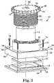
- FIG. 2is an exploded, perspective view of one embodiment of a camera module assembly of the digital camera of FIG. 1 .
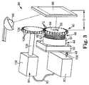
- FIG. 3is a perspective view of one embodiment of the camera module of FIG. 2 within a focus station.
- FIG. 4is a front view of one embodiment of a test target of the focusing station of FIG. 3 .
- FIG. 5is a focus optimization graph illustrating a general focus optimization concept.
- FIG. 6is a flow chart illustrating one embodiment of a focus optimization method for the camera module of FIG. 2 and based upon the concept of FIG. 5 .
- FIG. 7is a flow chart illustrating a process of determining variance of an image within the focus optimization process of FIG. 6 .
- FIG. 8is a front view illustrating shifting of a test target according to the focus optimization process of FIG. 6 .
- FIG. 1is a block diagram illustrating major components of a digital camera 10 .
- Camera 10includes a lens 12 , an image sensor 14 , a shutter controller 16 , a processor 18 , a memory 20 , an input/output (I/O) interface 22 , a shutter button 24 , a liquid crystal display (LCD) 26 , and a user input device 28 .
- I/Oinput/output
- processor 18 and shutter controller 16cause image sensor 14 to capture light bouncing off of a subject (not shown) through lens 12 .
- Image sensor 14converts the captured light into pixel data, and outputs the pixel date representative of the image to processor 18 .
- memory 20includes a type of random access memory (RAM) and non-volatile memory, but can include any suitable type of memory storage.
- memory 20includes a type or programmable read-only memory (PROM) such as electrically erasable programmable read-only memory (EEPROM).
- PROMprogrammable read-only memory
- EEPROMelectrically erasable programmable read-only memory
- I/O interface 22is configured to be coupled to a computer or other appropriate electronic device (e.g., a PDA, a mobile or cellular telephone, etc), for transferring information between the electronic device and digital camera 10 including downloading captured images from camera 10 to the electronic device.
- a computer or other appropriate electronic devicee.g., a PDA, a mobile or cellular telephone, etc
- User input device 28allows a user to vary the user definable settings of the camera 10 .
- FIG. 2illustrates an exploded view of a fixed-focus camera module 40 for use in conventional digital cameras 10 or for incorporating into other electronic devices such as components, PDAs, cellular phones, etc.
- Camera module 40includes image sensor 14 , an optional infrared filter (IRF) 42 , a housing 44 , lens 12 , and a barrel 46 .
- image sensor 14is a charge couple device (CCD) or a complimentary metal oxide semiconductor (CMOS) device.
- CCDcharge couple device
- CMOScomplimentary metal oxide semiconductor
- image sensor 14not only is capable of capturing images but also includes circuitry able to process the captured images.
- Image sensor 14is connected to an output pin 48 or other communication device extending from image sensor 14 to a point external to housing 44 .
- Output pin 48permits signals or other information to be communicated to other devices. In one embodiment, outlet pin 48 outputs an analog of binary signal.
- image sensor 14is adapted to function under at least two modes including a general video or photograph output mode and a focus test mode, as will be further described below.
- image sensor 14is mounted to a substrate or housing bottom 49 .
- IRF 42is placed upon image sensor 14 . IRF 42 filters the light captured by camera module 40 to decrease the contamination of image sensor 14 with infrared (non-visible) light.
- housing 44includes a base portion 50 and an extension portion 52 .
- Base portion 50includes four side walls 54 collectively assembled to form base portion 50 in a rectangular manner.
- a planar member 56partially extends between an edge of side walls 54 .
- Extension portion 52extends from an external surface 58 of planar member 56 .
- extension portion 52is centered with respect to side walls 54 .
- Extension portion 52is annular in shape and defines an inner threaded surface 60 .
- extension portion 52is integrally and homogenously formed with base portion 50 . In other embodiments, extension portion 52 is integrally secured to base portion 50 .
- Barrel 46defines a first annular portion 62 and a second generally annular portion 64 .
- First annular portion 62defines an outer threaded surface 66 configured to selectively interact with inner threaded surface 60 of housing 44 .
- First annular portion 62is hollow or tubular in order to circumferentially encompass a lens 12 .
- Second annular portion 64 of barrel 46extends radially outward and inwardly from first annular portion 62 .
- An aperture 68is defined in the center of second annular portion 64 .
- Aperture 68is preferably circular.
- Second annular portion 64defines an overall outer diameter greater than an overall outer diameter defined by threaded surface 66 of first annular portion 62 .
- an outer periphery 70 of second annular portion 64defines a plurality of teeth 72 circumferentially spaced about outer periphery 70 . As such, second annular portion 64 substantially forms a toothed gear.
- IRF 42Upon assembly, IRF 42 is placed upon image sensor 14 .
- Housing 44is secured to substrate 49 to interpose IRF 42 between image sensor 14 and housing 44 .
- threaded screws 74 or other fasteners, such as spring clips, etc.are used to couple housing 44 to substrate 49 .
- housing 44is attached to substrate 49 or image sensor 14 with an adhesive or other compound rather than with fasteners 74 .
- housing 44is coupled to substrate 49 with adhesive and fasteners 74 .
- Lens 12is sized to be secured within first annular portion 62 of barrel 46 .
- lens 12has a circumferential outer perimeter that interacts with an inner circumference of first annular portion 62 .
- Barrel 46is placed at least partially within extension portion 52 of housing 44 .
- barrel 46is placed such that threaded outer surface 66 of barrel 46 interacts with threaded inner surface 60 of extension portion 52 to selectively secure lens 12 and barrel 46 to housing 44 .
- Rotation of barrel 46causes barrel 46 to move either further into or further out of extension portion 52 of housing 44 .
- rotation of barrel 46also serves to move lens 12 either closer to or further way from image sensor 14 .
- Rotation of barrel 46 and the resulting movement of lens 12 with respect to image sensor 14thereby, allows camera module 40 to be generally focused.
- Focusing station 80includes a microcontroller 82 , an actuating assembly 84 , a test target 86 , and a light source 88 .
- Microcontroller 82is adapted to interface with camera module 40 and is electrically connected to actuating assembly 84 , such as via an electrical connection 90 .
- microcontroller 82includes a module interface 100 for coupling with output pin 48 of camera module 40 .
- module interface 100is configured to receive at least one of analog or binary communication signal from output pin 48 .
- microcontroller 82is characterized by an inability to receive video communication from camera module 40 .
- actuating assembly 84includes a motor 102 , a shaft 104 , and a toothed wheel or gear 106 .
- Shaft 104is electrically coupled to motor 102 , which is configured to selectively rotate shaft 104 about its longitudinal axis as directed by microcontroller 82 .
- Gear 106is coupled to shaft 104 opposite motor 102 .
- rotation of shaft 104also induces rotation to gear 106 about an axis of shaft 104 .
- gear 106includes a plurality of teeth 108 extending radially from the remainder of gear 106 and circumferentially spaced from each other about the entire periphery of gear 106 .
- actuating assembly 84is positioned with respect to microcontroller 82 so a portion of teeth 108 of gear 106 interface with a portion of teeth 72 of camera module 40 when microcontroller 82 is coupled with camera module 40 . Accordingly, upon rotation of gear 106 , barrel 46 will be rotated at a similar speed but in an opposite direction.
- Test target 86is generally planar and is spaced from microcontroller 82 such that upon selective coupling of microcontroller 82 with camera module 40 , camera module 40 will be directed toward test target 86 to capture an image of test target 86 .
- test target 86is positioned such that upon placement of camera module 40 within focusing station 80 , camera module 40 will be positioned a distance D from test target 86 .
- distance Dis equal to about a hyperfocal distance of lens 12 of camera module 40 .
- test target 86includes at least one high contrast figure or object.
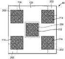
- test target 86includes a white or generally white background 110 with at least one solid black figure or object 112 having definite boundary lines from background 110 . Otherwise stated, the boundary lines between background 110 and FIG. 112 are not blurred or gradual but are definite and crisp.
- object 112is any solid color with high contrast to the color of background 110 .
- test target 86includes a plurality of solid test objects 112 on background 110 .
- test target 86includes object 112 in positioned near the center of test target 86 and additionally includes a plurality of additional test objects 114 positioned relatively nearer to and spaced about the periphery of test target 86 .
- test target 86is formed in a general checkerboard-like pattern. Referring to FIG. 3 , light source 88 is directed towards test target 86 and provides test target 86 with illumination and light, which will bounce off test target 86 to be captured by lens 12 of camera module 40 .
- camera module 40is received by focusing station 80 . More particularly, camera module 40 is positioned within focusing station 80 to couple output pin 48 with module interface 100 of microcontroller 82 . Camera module 40 is also positioned to be directed toward a test target 86 and so a portion of teeth 72 of barrel 46 interface with a portion of the teeth 108 of gear 106 .
- optimum focusrefers to the best relative focus level that can be achieved for camera module 40 when the position of lens 12 is adjusted at predetermined increments. Accordingly, optimum focus is not an absolute level of best possible focus.
- lens 12would not be positioned to provide the optimum focus quality. If the distance between lens 12 and image sensor 14 is decreased from point 128 , focus quality would decrease accordingly. Alternatively, if the distance between the lens 12 and image sensor 14 was increased from point 128 , focus quality of camera module 40 would increase.
- FIG. 6is a flow chart illustrating one embodiment of a focus optimization process generally at 150 , which is best described with additional reference to FIG. 3 , based upon the concept of FIG. 5 .
- camera module 40is placed within focusing station 80 .
- camera module 40is positioned to be selectively coupled with microcontroller 82 and lens 12 is directed toward and to capture test target 86 .
- camera module 40is spaced from but centered with respect to test target 86 .
- focusing station 80additionally includes a jig or other member (not illustrated) to assist in proper positioning of camera module 40 within focusing station 80 .
- a portion of gear teeth 108 of actuating assembly 84interface with a portion of teeth 72 of camera module barrel 46 .
- camera module 40is electrically coupled to focusing station 80 .
- microcontroller 82 module interface 100receives output pin 48 of camera module 40 to receive at least one of analog or binary signals from camera module 40 .
- camera module 40is operated to capture an image depicting test target 86 .
- camera module 40is in a focus mode, rather than the general photography or video mode. Accordingly, upon capturing the image of test target 86 , camera module 40 does not directly output a digital representation of the image or video storage.
- the image depicting test target 86captures the entirety of test target 86 .
- the image depicting test target 86depicts background 110 as well as an entirety of objects 112 and 114 .
- a variance of a spatial first derivative of the imageis determined by image sensor 14 (illustrated in FIG. 2 ) within camera module 40 . Additionally referring to FIG. 7 , in one embodiment, determining the variance of the image at 158 includes deriving a spatial first derivative of the image at 160 .
- the first step of deriving the spatial first derivative of the imageis shifting the original image by one pixel at 162 .
- the initial or original image 164depicts test target 86 and accordingly includes representations 167 and 168 depicting objects 112 and 114 (illustrated in FIG. 4 ), respectively.
- the original image 164which is temporarily stored by image sensor 14 , is shifted in one direction by one pixel. In the embodiment illustrated in FIG. 8 , original image 164 is shifted one pixel in a negative X direction as indicated by arrow 170 to produce a shifted image, which is generally indicated with broken lines at 164 ′.
- shifted image 164 ′is subtracted from original image 164 at each pixel being analyzed. For example, in a properly focused image 164 , pixel 174 appears as a black pixel. Alternatively, in shifted image 164 ′, pixel 174 appears as a white pixel similar to the target background 110 (illustrated in FIG. 4 ). By subtracting shifted image 164 ′ from original image 164 at pixel 174 , a large positive difference is found at pixel 174 due to the extreme difference between black and white.
- original image 164provides pixel 176 as white
- shifted image 164 ′provides pixel 176 as black.
- a large negative differenceis found.
- the pixelsremain either one of black or white in each of images 164 and 164 ′ resulting in zero difference upon subtraction.
- pixel 174may appear gray in original image 164 and/or shifted image 164 ′. Therefore, upon subtraction of shifted image 164 ′ from original image 164 , a relatively lesser positive difference and lesser negative difference would be derived at pixels 174 and 176 , respectively. Accordingly, the larger the absolute value for the pixel difference or derivative generally indicates that original image 164 is in better focus than an alternative low absolute value for the difference or derivative at each pixel. Accordingly, once shifted image 164 ′ is subtracted from original image 164 at each pixel, the first derivative, otherwise known as a spatial derivative, is determined for the image 164 .
- the difference or derivative found at each pixel in 166is squared to account for the negative or positive characteristic of the result. By squaring the difference at each pixel, negative differences can be compared directly with positive differences wherein higher absolute or squared values generally indicate a higher degree of focus.
- the squared values arrived at 180are added together to determine a sum of the squared pixel derivatives or differences to arrive at the variance of the spatial first derivative of the image.
- the varianceprovides a focus metric of the image 164 is a direct indication of the focus quality of camera module 40 . More specifically, the higher the variance of the spatial first derivative of image 164 the better the focus quality of camera module 40 .
- the varianceis output from camera module 40 to microcontroller 82 via the electrical connection between microcontroller 82 and camera module 40 .
- the varianceis output to microcontroller 82 as an analog signal. More specifically, the relative variance level is output with differing levels of voltage to microcontroller 82 , where higher voltages indicate higher variances and vice versa. Accordingly, the voltage level output is directly proportionate to the variance and focus quality.
- the camera moduleoutputs binary communication, such as a +1 value when variance is improving at ⁇ 1 value when variance is decreasing. In this embodiment, additional comparative steps of the focus optimization process are completed by the image sensor rather than the focusing station microcontroller.
- microcontroller 82determines if this was the first time through the focus optimization process 150 . If it is determined this was the first time through the focus optimization process 150 , then at 188 , microcontroller 82 signals motor 102 to rotate gear 106 in a first direction by a predetermined increment of rotation. Since teeth 108 of gear 106 interact with teeth 72 of barrel 46 , rotating of the gear 106 causes barrel 46 of image controller to also rotate. Due to the threaded connection between barrel 46 and housing 44 , the rotation of barrel 46 , and therefore lens 12 , moves both barrel 46 and lens 12 further into housing or further out of housing 44 a predetermined increment or amount.
- microcontroller 82determines if the variance related signal is improving as compared to the variance related signal received the previous time through the sequence. In particular, if the second variance related signal is higher than the first variance related signal, then the variance related signal is improving. Conversely, if the second variance related signal is less than the first variance related signal, then the variance related signal is not improving.
- the microcontroller 82signals actuating assembly 84 to adjust the distance between lens 12 and image sensor 14 in the same direction lens 12 was previously adjusted at step 188 .
- actuating assembly 84rotates gear 106 clockwise at step 188
- actuating assembly 84would once again rotate gear 106 clockwise.
- the distance between lens 12 and image sensor 14is changed by a predetermined increment in the range of about 2 microns to about 20 microns. In a more particular embodiment, each predetermined increment is in the range of about 5 microns to about 10 microns.
- steps 156 , 158 , 184 , 186 , and 190are repeated. If at 190 , it is determined that the variance related signal is not improving, then at 194 , microcontroller 82 signals actuating assembly 84 to adjust the distance lens 12 extends from image sensor 14 (illustrated in FIG. 2 ) in a direction opposite the direction lens 12 was adjusted in the most recent previous step 188 or 192 . Otherwise stated, if the motor 102 rotated gear 106 in a clockwise direction in previous step 188 or 192 , then at 194 , motor 102 rotates gear 106 in a counterclockwise direction. Accordingly, barrel 46 with lens 12 , which was initially moved one increment closer to image sensor 14 via the clockwise rotation of gear 106 , would now be moved one increment further away from image sensor 14 via the counterclockwise rotation of gear 106 .
- microcontroller 82determines if the variance related signal was improving prior to the most recent completion of step 190 . If is determined at 196 that the variance related signal was previously improving, it indicates that the focus quality or variance was increasing towards the point of optimum focus (see point 126 in FIG. 5 ) and actually passed beyond the point of optimum focus 126 to decrease overall focus quality. Therefore, the adjustment of the distance between lens 12 and image sensor 14 back by a single increment at 194 returns lens 12 to a distance from image sensor 14 corresponding to the point of optimum module focus. Therefore, focus testing and fixing is complete, and at 198 , the camera module is forwarded to the next stage of manufacture.
- step 198focus optimization process 150 continues to step 198 , described above, where optimum focus of camera module 40 is achieved and the focus of camera module 40 is fixed (i.e. the distance between lens 12 and image sensor 14 is fixed so as not to be adjustable during use of camera module 40 ).
- lens 12is moved from the first discovery of decreasing variance following previous improvements in variance a known offset distance in either direction to achieve a desired level of optimum focus.
- lens 12is moved in the opposite direction to once again pass point of optimum focus 126 to effectively define a range of optimum focus.
- lens 12is moved either to the midpoint of the identified range of optimum focus or moved a predetermined offset from the midpoint to rest at the desired point of optimum focus.
- the method chosen to determine the desired point of optimum focusis dependent at least in part upon the mechanical tolerance and precision of camera module 40 and focusing station 80 .
- a focus optimization process and system as described abovepermits a large amount of the test process to be actually completed by the image sensor rather than by the focusing station.
- the hardware and assembly time of the focusing stationcan be decreased. More particularly in one embodiment, the focusing station would no longer require a computer processing unit with complicated hardware, such as frame grabbers, and associated software.
- the focusing systemmerely requires a microcontroller to perform nominal processing tasks and to signal actuating assembly to alter the distance the lens is spaced from the image sensor.
- the overall cost of providing a focusing stationis decreased.
- the speed of the focus optimization processis increased.
- the speed of the focus optimization process 150can further be increased by additionally altering the process of determining the variance of the image depicting test target 86 .
- the process of determining the variance of the image depicting test target 86For example, as illustrated with additional reference to FIG. 4 , rather than analyzing the entire area of the original image depicting the test target 86 , only the areas of the image depicting at least one region of interest generally indicated by broken lines 200 are analyzed.
- the focus test mode of camera module 40may be configured to only analyze region of interest 200 of the original image. Since region of interest 200 depicts at least a portion of the background 110 as well as a portion of the object 112 including a boundary line between background 110 and object 112 , a similar method of determining the variance is completed as that described above except for only region of interest 200 rather than the entire original image is considered. Accordingly, since less pixels are analyzed, the overall time needed to complete the focus optimization process is decreased.
- image sensor 14is programmed with prior knowledge of the layout of test target 86 to ensure the analyzed region of interest 200 includes a portion of background 120 and a portion of test object 112 as well as the boundary line formed therebetween.
- multiple regions of interestare selected from within the original image and are used to determine the variance of the image. For example, in one embodiment, not only is region of interest 200 identified but additional regions of interest 202 are also identified and analyzed. In one embodiment, regions of interest 200 and 202 are spaced throughout the original image so the overall focus level achieved by focus optimization method 150 is more indicative of the focus of the image being captured.
- each region of interest 200 or 202includes at least a portion of background 110 and object 112 or 114 including a boundary between background 110 and object 112 or 114 .
- regions of interest 200 and 202collectively define less than 50% of the entire captured image. In one embodiment, each region of interest 200 and 202 individually define less than 25% of the captured image.
- each region of interest 200 and/or 202individually defines about 5% of the captured image.
- the same general focus optimization method 150 described aboveis utilized.
- each region of interestdefines less than 2% of the captured image, and the plurality of regions of interest collectively define less than 10% of the captured image.
- the overall speed of completing the focus optimization method 150is increased.
Landscapes
- Physics & Mathematics (AREA)
- General Physics & Mathematics (AREA)
- Optics & Photonics (AREA)
- Engineering & Computer Science (AREA)
- Multimedia (AREA)
- Signal Processing (AREA)
- Health & Medical Sciences (AREA)
- Biomedical Technology (AREA)
- General Health & Medical Sciences (AREA)
- Automatic Focus Adjustment (AREA)
- Studio Devices (AREA)
- Focusing (AREA)
- Lens Barrels (AREA)
Abstract
Description
Claims (28)
Priority Applications (4)
| Application Number | Priority Date | Filing Date | Title |
|---|---|---|---|
| US10/989,615US7598996B2 (en) | 2004-11-16 | 2004-11-16 | System and method for focusing a digital camera |
| JP2005325097AJP2006146207A (en) | 2004-11-16 | 2005-11-09 | System and method for focusing a digital camera |
| GB0523368AGB2420239B (en) | 2004-11-16 | 2005-11-16 | System and method for focusing a digital camera |
| US12/546,888US7990460B2 (en) | 2004-11-16 | 2009-08-25 | System and method for focusing a digital camera |
Applications Claiming Priority (1)
| Application Number | Priority Date | Filing Date | Title |
|---|---|---|---|
| US10/989,615US7598996B2 (en) | 2004-11-16 | 2004-11-16 | System and method for focusing a digital camera |
Related Child Applications (1)
| Application Number | Title | Priority Date | Filing Date |
|---|---|---|---|
| US12/546,888ContinuationUS7990460B2 (en) | 2004-11-16 | 2009-08-25 | System and method for focusing a digital camera |
Publications (2)
| Publication Number | Publication Date |
|---|---|
| US20060103754A1 US20060103754A1 (en) | 2006-05-18 |
| US7598996B2true US7598996B2 (en) | 2009-10-06 |
Family
ID=35580167
Family Applications (2)
| Application Number | Title | Priority Date | Filing Date |
|---|---|---|---|
| US10/989,615Expired - Fee RelatedUS7598996B2 (en) | 2004-11-16 | 2004-11-16 | System and method for focusing a digital camera |
| US12/546,888Expired - LifetimeUS7990460B2 (en) | 2004-11-16 | 2009-08-25 | System and method for focusing a digital camera |
Family Applications After (1)
| Application Number | Title | Priority Date | Filing Date |
|---|---|---|---|
| US12/546,888Expired - LifetimeUS7990460B2 (en) | 2004-11-16 | 2009-08-25 | System and method for focusing a digital camera |
Country Status (3)
| Country | Link |
|---|---|
| US (2) | US7598996B2 (en) |
| JP (1) | JP2006146207A (en) |
| GB (1) | GB2420239B (en) |
Cited By (6)
| Publication number | Priority date | Publication date | Assignee | Title |
|---|---|---|---|---|
| US20050167499A1 (en)* | 2004-01-26 | 2005-08-04 | Shuichiro Ogasawara | Method and apparatus for estimating the imaging capability of an image-formation optical system |
| US20080129858A1 (en)* | 2006-12-01 | 2008-06-05 | Hon Hai Precision Industry Co., Ltd. | Auto-focus imaging system |
| US20080151098A1 (en)* | 2006-12-20 | 2008-06-26 | Hon Hai Precision Industry Co., Ltd. | Camera module |
| US20110102603A1 (en)* | 2009-11-02 | 2011-05-05 | Hong Fu Jin Precision Industry (Shenzhen) Co., Ltd. | System and method for testing a camera module of an electronic device |
| US20140049683A1 (en)* | 2012-08-20 | 2014-02-20 | Microsoft Corporation | Dynamically Curved Sensor for Optical Zoom Lens |
| CN103906965A (en)* | 2011-10-27 | 2014-07-02 | 罗伯特·博世有限公司 | Adjustment arrangement |
Families Citing this family (105)
| Publication number | Priority date | Publication date | Assignee | Title |
|---|---|---|---|---|
| TWI224860B (en)* | 2004-03-18 | 2004-12-01 | Pixart Imaging Inc | Automatically-packaging apparatus which can package an optical sensing module with a preferred distance between a lens and an optical sensor |
| US7531773B2 (en) | 2005-09-08 | 2009-05-12 | Flextronics Ap, Llc | Auto-focus and zoom module having a lead screw with its rotation results in translation of an optics group |
| US20070133969A1 (en)* | 2005-12-12 | 2007-06-14 | Ess Technology, Inc. | System and method for measuring and setting the focus of a camera assembly |
| US20070165131A1 (en)* | 2005-12-12 | 2007-07-19 | Ess Technology, Inc. | System and method for measuring tilt of a sensor die with respect to the optical axis of a lens in a camera module |
| KR100770684B1 (en)* | 2006-05-18 | 2007-10-29 | 삼성전기주식회사 | Camera module package |
| US8112128B2 (en)* | 2006-08-31 | 2012-02-07 | Flextronics Ap, Llc | Discreetly positionable camera housing |
| TWI382212B (en)* | 2006-12-15 | 2013-01-11 | Hon Hai Prec Ind Co Ltd | Apparatus and method for assembling lens modules |
| CA2685080A1 (en) | 2007-04-24 | 2008-11-06 | Flextronics Ap Llc | Small form factor modules using wafer level optics with bottom cavity and flip-chip assembly |
| US8083421B2 (en)* | 2007-05-07 | 2011-12-27 | Flextronics Ap, Llc | AF/zoom shutter with two blades function |
| US7825985B2 (en) | 2007-07-19 | 2010-11-02 | Flextronics Ap, Llc | Camera module back-focal length adjustment method and ultra compact components packaging |
| CN101350888B (en)* | 2007-07-20 | 2011-08-24 | 鸿富锦精密工业(深圳)有限公司 | Image capture device and its automatic focusing method |
| JP4962194B2 (en)* | 2007-08-02 | 2012-06-27 | 富士通株式会社 | Image input module adjustment apparatus and image input module adjustment method |
| US9192296B2 (en) | 2007-08-21 | 2015-11-24 | Visionix Ltd. | Multifunctional ophthalmic measurement system |
| US8488046B2 (en)* | 2007-12-27 | 2013-07-16 | Digitaloptics Corporation | Configurable tele wide module |
| JP5198295B2 (en)* | 2008-01-15 | 2013-05-15 | 富士フイルム株式会社 | Image sensor position adjustment method, camera module manufacturing method and apparatus, and camera module |
| DK3876510T3 (en) | 2008-05-20 | 2024-11-11 | Adeia Imaging Llc | CAPTURE AND PROCESSING OF IMAGES USING MONOLITHIC CAMERA ARRAY WITH HETEROGENEOUS IMAGES |
| US11792538B2 (en) | 2008-05-20 | 2023-10-17 | Adeia Imaging Llc | Capturing and processing of images including occlusions focused on an image sensor by a lens stack array |
| US8866920B2 (en) | 2008-05-20 | 2014-10-21 | Pelican Imaging Corporation | Capturing and processing of images using monolithic camera array with heterogeneous imagers |
| TWI413003B (en)* | 2008-07-23 | 2013-10-21 | Altek Corp | Face recognition of the automatic camera method |
| US9288449B2 (en)* | 2008-08-05 | 2016-03-15 | University Of Florida Research Foundation, Inc. | Systems and methods for maintaining multiple objects within a camera field-of-view |
| US20100079602A1 (en)* | 2008-09-26 | 2010-04-01 | Silverbrook Research Pty Ltd. | Method and apparatus for alignment of an optical assembly with an image sensor |
| JP2010114731A (en)* | 2008-11-07 | 2010-05-20 | Toshiba Corp | Method for manufacturing camera module |
| GB0821503D0 (en) | 2008-11-25 | 2008-12-31 | St Microelectronics Res & Dev | Optical component focus testing apparatus and method |
| EP2502115A4 (en) | 2009-11-20 | 2013-11-06 | Pelican Imaging Corp | CAPTURE AND IMAGE PROCESSING USING A MONOLITHIC CAMERAS NETWORK EQUIPPED WITH HETEROGENEOUS IMAGERS |
| TWI495335B (en)* | 2010-04-21 | 2015-08-01 | Hon Hai Prec Ind Co Ltd | Lens module and method of operating the same |
| US8928793B2 (en) | 2010-05-12 | 2015-01-06 | Pelican Imaging Corporation | Imager array interfaces |
| TWI465788B (en)* | 2010-06-21 | 2014-12-21 | Hon Hai Prec Ind Co Ltd | Camera module and method for assemblying the same |
| TWI479219B (en)* | 2010-06-22 | 2015-04-01 | Hon Hai Prec Ind Co Ltd | Camera module and method for assemblying the same |
| CN102375291B (en)* | 2010-08-10 | 2014-11-05 | 昆山钜亮光电科技有限公司 | Coaxial synchronous automatic focus light box mechanism of camera module |
| US20120057016A1 (en)* | 2010-09-04 | 2012-03-08 | Cheng Uei Precision Industry Co., Ltd. | Multifunctional working platform for the process of an image sensor module |
| US8878950B2 (en) | 2010-12-14 | 2014-11-04 | Pelican Imaging Corporation | Systems and methods for synthesizing high resolution images using super-resolution processes |
| US8545114B2 (en) | 2011-03-11 | 2013-10-01 | Digitaloptics Corporation | Auto focus-zoom actuator or camera module contamination reduction feature with integrated protective membrane |
| EP2708019B1 (en) | 2011-05-11 | 2019-10-16 | FotoNation Limited | Systems and methods for transmitting and receiving array camera image data |
| KR20140045458A (en) | 2011-06-28 | 2014-04-16 | 펠리칸 이매징 코포레이션 | Optical arrangements for use with an array camera |
| US20130265459A1 (en) | 2011-06-28 | 2013-10-10 | Pelican Imaging Corporation | Optical arrangements for use with an array camera |
| US8982267B2 (en) | 2011-07-27 | 2015-03-17 | Flextronics Ap, Llc | Camera module with particle trap |
| US20130070060A1 (en) | 2011-09-19 | 2013-03-21 | Pelican Imaging Corporation | Systems and methods for determining depth from multiple views of a scene that include aliasing using hypothesized fusion |
| CN104081414B (en) | 2011-09-28 | 2017-08-01 | Fotonation开曼有限公司 | Systems and methods for encoding and decoding light field image files |
| DE102012200152A1 (en)* | 2012-01-05 | 2013-07-11 | Robert Bosch Gmbh | Device and method for measuring a camera |
| EP2817955B1 (en) | 2012-02-21 | 2018-04-11 | FotoNation Cayman Limited | Systems and methods for the manipulation of captured light field image data |
| WO2013136053A1 (en)* | 2012-03-10 | 2013-09-19 | Digitaloptics Corporation | Miniature camera module with mems-actuated autofocus |
| US9156168B2 (en) | 2012-04-13 | 2015-10-13 | Automation Engineering, Inc. | Active alignment using continuous motion sweeps and temporal interpolation |
| US9210392B2 (en) | 2012-05-01 | 2015-12-08 | Pelican Imaging Coporation | Camera modules patterned with pi filter groups |
| JP2015534734A (en) | 2012-06-28 | 2015-12-03 | ペリカン イメージング コーポレイション | System and method for detecting defective camera arrays, optical arrays, and sensors |
| US20140002674A1 (en) | 2012-06-30 | 2014-01-02 | Pelican Imaging Corporation | Systems and Methods for Manufacturing Camera Modules Using Active Alignment of Lens Stack Arrays and Sensors |
| PL4296963T3 (en) | 2012-08-21 | 2025-04-28 | Adeia Imaging Llc | Method for depth detection in images captured using array cameras |
| WO2014032020A2 (en) | 2012-08-23 | 2014-02-27 | Pelican Imaging Corporation | Feature based high resolution motion estimation from low resolution images captured using an array source |
| US9214013B2 (en) | 2012-09-14 | 2015-12-15 | Pelican Imaging Corporation | Systems and methods for correcting user identified artifacts in light field images |
| EP4307659A1 (en) | 2012-09-28 | 2024-01-17 | Adeia Imaging LLC | Generating images from light fields utilizing virtual viewpoints |
| US9746636B2 (en) | 2012-10-19 | 2017-08-29 | Cognex Corporation | Carrier frame and circuit board for an electronic device |
| US9513458B1 (en) | 2012-10-19 | 2016-12-06 | Cognex Corporation | Carrier frame and circuit board for an electronic device with lens backlash reduction |
| WO2014078443A1 (en) | 2012-11-13 | 2014-05-22 | Pelican Imaging Corporation | Systems and methods for array camera focal plane control |
| US9462164B2 (en) | 2013-02-21 | 2016-10-04 | Pelican Imaging Corporation | Systems and methods for generating compressed light field representation data using captured light fields, array geometry, and parallax information |
| US9374512B2 (en) | 2013-02-24 | 2016-06-21 | Pelican Imaging Corporation | Thin form factor computational array cameras and modular array cameras |
| US9225977B2 (en) | 2013-02-25 | 2015-12-29 | Teradyne, Inc. | Matrix testing targets |
| US8947537B2 (en)* | 2013-02-25 | 2015-02-03 | Teradyne, Inc. | Rotatable camera module testing system |
| US9638883B1 (en)* | 2013-03-04 | 2017-05-02 | Fotonation Cayman Limited | Passive alignment of array camera modules constructed from lens stack arrays and sensors based upon alignment information obtained during manufacture of array camera modules using an active alignment process |
| US9774789B2 (en) | 2013-03-08 | 2017-09-26 | Fotonation Cayman Limited | Systems and methods for high dynamic range imaging using array cameras |
| US8866912B2 (en) | 2013-03-10 | 2014-10-21 | Pelican Imaging Corporation | System and methods for calibration of an array camera using a single captured image |
| US9521416B1 (en) | 2013-03-11 | 2016-12-13 | Kip Peli P1 Lp | Systems and methods for image data compression |
| US9124831B2 (en) | 2013-03-13 | 2015-09-01 | Pelican Imaging Corporation | System and methods for calibration of an array camera |
| US9106784B2 (en) | 2013-03-13 | 2015-08-11 | Pelican Imaging Corporation | Systems and methods for controlling aliasing in images captured by an array camera for use in super-resolution processing |
| WO2014165244A1 (en) | 2013-03-13 | 2014-10-09 | Pelican Imaging Corporation | Systems and methods for synthesizing images from image data captured by an array camera using restricted depth of field depth maps in which depth estimation precision varies |
| US9888194B2 (en) | 2013-03-13 | 2018-02-06 | Fotonation Cayman Limited | Array camera architecture implementing quantum film image sensors |
| US9578259B2 (en) | 2013-03-14 | 2017-02-21 | Fotonation Cayman Limited | Systems and methods for reducing motion blur in images or video in ultra low light with array cameras |
| WO2014153098A1 (en) | 2013-03-14 | 2014-09-25 | Pelican Imaging Corporation | Photmetric normalization in array cameras |
| US8786713B1 (en) | 2013-03-14 | 2014-07-22 | Automation Engineering, Inc. | Fixture for aligning auto-focus lens assembly to camera sensor |
| US9633442B2 (en) | 2013-03-15 | 2017-04-25 | Fotonation Cayman Limited | Array cameras including an array camera module augmented with a separate camera |
| US10122993B2 (en) | 2013-03-15 | 2018-11-06 | Fotonation Limited | Autofocus system for a conventional camera that uses depth information from an array camera |
| US9438888B2 (en) | 2013-03-15 | 2016-09-06 | Pelican Imaging Corporation | Systems and methods for stereo imaging with camera arrays |
| US9445003B1 (en) | 2013-03-15 | 2016-09-13 | Pelican Imaging Corporation | Systems and methods for synthesizing high resolution images using image deconvolution based on motion and depth information |
| US9497429B2 (en) | 2013-03-15 | 2016-11-15 | Pelican Imaging Corporation | Extended color processing on pelican array cameras |
| WO2014150856A1 (en) | 2013-03-15 | 2014-09-25 | Pelican Imaging Corporation | Array camera implementing quantum dot color filters |
| US9898856B2 (en) | 2013-09-27 | 2018-02-20 | Fotonation Cayman Limited | Systems and methods for depth-assisted perspective distortion correction |
| US9264592B2 (en) | 2013-11-07 | 2016-02-16 | Pelican Imaging Corporation | Array camera modules incorporating independently aligned lens stacks |
| US10119808B2 (en) | 2013-11-18 | 2018-11-06 | Fotonation Limited | Systems and methods for estimating depth from projected texture using camera arrays |
| WO2015081279A1 (en) | 2013-11-26 | 2015-06-04 | Pelican Imaging Corporation | Array camera configurations incorporating multiple constituent array cameras |
| US9766473B1 (en) | 2014-02-03 | 2017-09-19 | Automation Engineering, Inc. | Automated UV calibration, motorized optical target and automatic surface finder for optical alignment and assembly robot |
| US10089740B2 (en) | 2014-03-07 | 2018-10-02 | Fotonation Limited | System and methods for depth regularization and semiautomatic interactive matting using RGB-D images |
| US9247117B2 (en) | 2014-04-07 | 2016-01-26 | Pelican Imaging Corporation | Systems and methods for correcting for warpage of a sensor array in an array camera module by introducing warpage into a focal plane of a lens stack array |
| US9521319B2 (en) | 2014-06-18 | 2016-12-13 | Pelican Imaging Corporation | Array cameras and array camera modules including spectral filters disposed outside of a constituent image sensor |
| US9572715B2 (en) | 2014-07-25 | 2017-02-21 | Amo Manufacturing Usa, Llc | Systems, devices, and methods for calibration of beam profilers |
| JP2017531976A (en) | 2014-09-29 | 2017-10-26 | フォトネイション ケイマン リミテッド | System and method for dynamically calibrating an array camera |
| EP3076148B1 (en) | 2015-03-31 | 2019-05-08 | Trioptics GmbH | Device and method for measuring imaging properties of an optical imaging system |
| US9942474B2 (en) | 2015-04-17 | 2018-04-10 | Fotonation Cayman Limited | Systems and methods for performing high speed video capture and depth estimation using array cameras |
| US10440355B2 (en)* | 2015-11-06 | 2019-10-08 | Facebook Technologies, Llc | Depth mapping with a head mounted display using stereo cameras and structured light |
| US10482618B2 (en) | 2017-08-21 | 2019-11-19 | Fotonation Limited | Systems and methods for hybrid depth regularization |
| CN110072037B (en) | 2018-01-23 | 2020-09-22 | Oppo广东移动通信有限公司 | Camera assembly and electronics |
| DE102019106415B4 (en)* | 2019-03-13 | 2025-05-28 | Basler Ag | Camera housing, camera and assembly process |
| US11270110B2 (en) | 2019-09-17 | 2022-03-08 | Boston Polarimetrics, Inc. | Systems and methods for surface modeling using polarization cues |
| WO2021071992A1 (en) | 2019-10-07 | 2021-04-15 | Boston Polarimetrics, Inc. | Systems and methods for augmentation of sensor systems and imaging systems with polarization |
| DE112020005932T5 (en) | 2019-11-30 | 2023-01-05 | Boston Polarimetrics, Inc. | SYSTEMS AND METHODS FOR SEGMENTATION OF TRANSPARENT OBJECTS USING POLARIZATION CHARACTERISTICS |
| EP4081933A4 (en) | 2020-01-29 | 2024-03-20 | Intrinsic Innovation LLC | Systems and methods for characterizing object pose detection and measurement systems |
| US11797863B2 (en) | 2020-01-30 | 2023-10-24 | Intrinsic Innovation Llc | Systems and methods for synthesizing data for training statistical models on different imaging modalities including polarized images |
| US11953700B2 (en) | 2020-05-27 | 2024-04-09 | Intrinsic Innovation Llc | Multi-aperture polarization optical systems using beam splitters |
| US12020455B2 (en) | 2021-03-10 | 2024-06-25 | Intrinsic Innovation Llc | Systems and methods for high dynamic range image reconstruction |
| US12069227B2 (en) | 2021-03-10 | 2024-08-20 | Intrinsic Innovation Llc | Multi-modal and multi-spectral stereo camera arrays |
| US11954886B2 (en) | 2021-04-15 | 2024-04-09 | Intrinsic Innovation Llc | Systems and methods for six-degree of freedom pose estimation of deformable objects |
| US11290658B1 (en) | 2021-04-15 | 2022-03-29 | Boston Polarimetrics, Inc. | Systems and methods for camera exposure control |
| US12067746B2 (en) | 2021-05-07 | 2024-08-20 | Intrinsic Innovation Llc | Systems and methods for using computer vision to pick up small objects |
| US12175741B2 (en) | 2021-06-22 | 2024-12-24 | Intrinsic Innovation Llc | Systems and methods for a vision guided end effector |
| US12340538B2 (en) | 2021-06-25 | 2025-06-24 | Intrinsic Innovation Llc | Systems and methods for generating and using visual datasets for training computer vision models |
| US12172310B2 (en) | 2021-06-29 | 2024-12-24 | Intrinsic Innovation Llc | Systems and methods for picking objects using 3-D geometry and segmentation |
| US11689813B2 (en) | 2021-07-01 | 2023-06-27 | Intrinsic Innovation Llc | Systems and methods for high dynamic range imaging using crossed polarizers |
| US12293535B2 (en) | 2021-08-03 | 2025-05-06 | Intrinsic Innovation Llc | Systems and methods for training pose estimators in computer vision |
Citations (29)
| Publication number | Priority date | Publication date | Assignee | Title |
|---|---|---|---|---|
| US3932733A (en) | 1972-03-17 | 1976-01-13 | Bengt Olsen | Automatic focusing of an optical system |
| US4149792A (en) | 1977-12-30 | 1979-04-17 | Polaroid Corporation | Misfocus prevention means for cameras having unidirectional automatic focusing |
| US4348089A (en) | 1977-12-30 | 1982-09-07 | Polaroid Corporation | Lens movement actuated reference and sequencing means for cameras having unidirectional automatic focusing |
| US4456356A (en) | 1980-09-11 | 1984-06-26 | Nippon Kogaku K. K. | Focus adjusting device of a camera |
| US4465352A (en) | 1981-11-12 | 1984-08-14 | Asahi Kogaku Kogyo Kabushiki Kaisha | Automatic focusing device |
| EP0197734A2 (en) | 1985-03-29 | 1986-10-15 | Rank Cintel Limited | Microform reading apparatus |
| US5477296A (en) | 1993-03-30 | 1995-12-19 | Takamura; Masashi | Camera with a variable focus lens device |
| US5652924A (en) | 1994-09-30 | 1997-07-29 | Nikon Corp. | Automatic focus adjustment device and focus adjustment method |
| WO1997034194A1 (en) | 1996-03-14 | 1997-09-18 | Polaroid Corporation | Electronic still camera having mechanically movable ccd to affect focus |
| US5877809A (en)* | 1996-04-15 | 1999-03-02 | Eastman Kodak Company | Method of automatic object detection in image |
| US5973846A (en) | 1998-11-30 | 1999-10-26 | Hewlett-Packard Company | Offset spectra lens system for a two spectra automatic focusing system |
| US20020075393A1 (en) | 2000-12-15 | 2002-06-20 | Samsung Electro-Mechanics Co., Ltd. | Micro mode executing apparatus of digital still camera using focus driving motor |
| US20020179813A1 (en)* | 2001-05-29 | 2002-12-05 | Baer Richard L. | Contrast focus figure-of-merit method that is insensitive to scene illumination level |
| US20030063211A1 (en) | 2001-09-28 | 2003-04-03 | Nikon Corporation | Camera |
| US6563543B1 (en) | 1998-03-31 | 2003-05-13 | Hewlett-Packard Development Company, L.P. | Digital camera and method of using same |
| US20030117514A1 (en)* | 2001-12-21 | 2003-06-26 | Jonathan Weintroub | Method and apparatus for detecting optimum lens focus position |
| US6642956B1 (en) | 1998-05-29 | 2003-11-04 | Agilent Technologies, Inc. | Digital image processor for a digital camera |
| US20040017502A1 (en) | 2002-07-25 | 2004-01-29 | Timothy Alderson | Method and system for using an image based autofocus algorithm |
| US20040066563A1 (en)* | 2002-10-04 | 2004-04-08 | Voss James S. | Electronic imaging device focusing |
| US20040109080A1 (en) | 2002-12-05 | 2004-06-10 | Chan Wai San | Fixed-focus digital camera with defocus correction and a method thereof |
| GB2397394A (en) | 2003-01-03 | 2004-07-21 | Agilent Technologies Inc | Adjusting and fixing lens position in camera with a gear |
| US6771391B1 (en)* | 1999-01-21 | 2004-08-03 | Seiko Epson Corporation | Image forming method and device |
| US20040189862A1 (en) | 2003-03-31 | 2004-09-30 | Dialog Semiconductor Gmbh | Miniature camera module |
| US6822688B2 (en)* | 1996-01-31 | 2004-11-23 | Canon Kabushiki Kaisha | Movable-lens position control apparatus |
| US6839190B2 (en)* | 2002-07-31 | 2005-01-04 | Olympus Optical Co., Ltd. | Optical apparatus and imaging apparatus using the same |
| US6963388B1 (en)* | 1999-08-31 | 2005-11-08 | Canon Kabushiki Kaisha | Focus adjustment apparatus, control method therefor, and medium for supplying control program therefor |
| US6975348B2 (en)* | 2002-02-15 | 2005-12-13 | Inventec Corporation | Focusing method for a moving object |
| US7193196B2 (en)* | 2003-10-29 | 2007-03-20 | Lockheed Martin Corporation | Methods and systems for evaluating optical systems |
| US7233737B2 (en)* | 2003-08-12 | 2007-06-19 | Micron Technology, Inc. | Fixed-focus camera module and associated method of assembly |
Family Cites Families (2)
| Publication number | Priority date | Publication date | Assignee | Title |
|---|---|---|---|---|
| US5815748A (en)* | 1996-02-15 | 1998-09-29 | Minolta Co., Ltd. | Camera |
| EP1463342A1 (en)* | 2003-03-27 | 2004-09-29 | Dialog Semiconductor GmbH | Test system for camera modules |
- 2004
- 2004-11-16USUS10/989,615patent/US7598996B2/ennot_activeExpired - Fee Related
- 2005
- 2005-11-09JPJP2005325097Apatent/JP2006146207A/ennot_activeWithdrawn
- 2005-11-16GBGB0523368Apatent/GB2420239B/ennot_activeExpired - Fee Related
- 2009
- 2009-08-25USUS12/546,888patent/US7990460B2/ennot_activeExpired - Lifetime
Patent Citations (30)
| Publication number | Priority date | Publication date | Assignee | Title |
|---|---|---|---|---|
| US3932733A (en) | 1972-03-17 | 1976-01-13 | Bengt Olsen | Automatic focusing of an optical system |
| US4149792A (en) | 1977-12-30 | 1979-04-17 | Polaroid Corporation | Misfocus prevention means for cameras having unidirectional automatic focusing |
| US4348089A (en) | 1977-12-30 | 1982-09-07 | Polaroid Corporation | Lens movement actuated reference and sequencing means for cameras having unidirectional automatic focusing |
| US4456356A (en) | 1980-09-11 | 1984-06-26 | Nippon Kogaku K. K. | Focus adjusting device of a camera |
| US4465352A (en) | 1981-11-12 | 1984-08-14 | Asahi Kogaku Kogyo Kabushiki Kaisha | Automatic focusing device |
| EP0197734A2 (en) | 1985-03-29 | 1986-10-15 | Rank Cintel Limited | Microform reading apparatus |
| US5477296A (en) | 1993-03-30 | 1995-12-19 | Takamura; Masashi | Camera with a variable focus lens device |
| US5652924A (en) | 1994-09-30 | 1997-07-29 | Nikon Corp. | Automatic focus adjustment device and focus adjustment method |
| US6822688B2 (en)* | 1996-01-31 | 2004-11-23 | Canon Kabushiki Kaisha | Movable-lens position control apparatus |
| WO1997034194A1 (en) | 1996-03-14 | 1997-09-18 | Polaroid Corporation | Electronic still camera having mechanically movable ccd to affect focus |
| US5877809A (en)* | 1996-04-15 | 1999-03-02 | Eastman Kodak Company | Method of automatic object detection in image |
| US6563543B1 (en) | 1998-03-31 | 2003-05-13 | Hewlett-Packard Development Company, L.P. | Digital camera and method of using same |
| US6642956B1 (en) | 1998-05-29 | 2003-11-04 | Agilent Technologies, Inc. | Digital image processor for a digital camera |
| US5973846A (en) | 1998-11-30 | 1999-10-26 | Hewlett-Packard Company | Offset spectra lens system for a two spectra automatic focusing system |
| US6771391B1 (en)* | 1999-01-21 | 2004-08-03 | Seiko Epson Corporation | Image forming method and device |
| US6963388B1 (en)* | 1999-08-31 | 2005-11-08 | Canon Kabushiki Kaisha | Focus adjustment apparatus, control method therefor, and medium for supplying control program therefor |
| US20020075393A1 (en) | 2000-12-15 | 2002-06-20 | Samsung Electro-Mechanics Co., Ltd. | Micro mode executing apparatus of digital still camera using focus driving motor |
| US20020179813A1 (en)* | 2001-05-29 | 2002-12-05 | Baer Richard L. | Contrast focus figure-of-merit method that is insensitive to scene illumination level |
| US20030063211A1 (en) | 2001-09-28 | 2003-04-03 | Nikon Corporation | Camera |
| US20030117514A1 (en)* | 2001-12-21 | 2003-06-26 | Jonathan Weintroub | Method and apparatus for detecting optimum lens focus position |
| US6975348B2 (en)* | 2002-02-15 | 2005-12-13 | Inventec Corporation | Focusing method for a moving object |
| US20040017502A1 (en) | 2002-07-25 | 2004-01-29 | Timothy Alderson | Method and system for using an image based autofocus algorithm |
| US6839190B2 (en)* | 2002-07-31 | 2005-01-04 | Olympus Optical Co., Ltd. | Optical apparatus and imaging apparatus using the same |
| US20040066563A1 (en)* | 2002-10-04 | 2004-04-08 | Voss James S. | Electronic imaging device focusing |
| US20040109080A1 (en) | 2002-12-05 | 2004-06-10 | Chan Wai San | Fixed-focus digital camera with defocus correction and a method thereof |
| GB2397394A (en) | 2003-01-03 | 2004-07-21 | Agilent Technologies Inc | Adjusting and fixing lens position in camera with a gear |
| US7215374B2 (en)* | 2003-01-03 | 2007-05-08 | Micron Technology, Inc. | Camera module having geared lens barrel |
| US20040189862A1 (en) | 2003-03-31 | 2004-09-30 | Dialog Semiconductor Gmbh | Miniature camera module |
| US7233737B2 (en)* | 2003-08-12 | 2007-06-19 | Micron Technology, Inc. | Fixed-focus camera module and associated method of assembly |
| US7193196B2 (en)* | 2003-10-29 | 2007-03-20 | Lockheed Martin Corporation | Methods and systems for evaluating optical systems |
Non-Patent Citations (3)
| Title |
|---|
| British Patent Application No. 0523368.9 Search Report dated Jul. 25, 2006. |
| British Patent Application No. 0523368.9 Search Report dated Jul. 26, 2006. |
| British Patent Application No. 0523368.9 Search Report dated Jul. 27, 2006. |
Cited By (12)
| Publication number | Priority date | Publication date | Assignee | Title |
|---|---|---|---|---|
| US20050167499A1 (en)* | 2004-01-26 | 2005-08-04 | Shuichiro Ogasawara | Method and apparatus for estimating the imaging capability of an image-formation optical system |
| US8259180B2 (en)* | 2004-01-26 | 2012-09-04 | Olympus Corporation | Method and apparatus for estimating the imaging capability of an image-formation optical system |
| US20080129858A1 (en)* | 2006-12-01 | 2008-06-05 | Hon Hai Precision Industry Co., Ltd. | Auto-focus imaging system |
| US20080151098A1 (en)* | 2006-12-20 | 2008-06-26 | Hon Hai Precision Industry Co., Ltd. | Camera module |
| US20110102603A1 (en)* | 2009-11-02 | 2011-05-05 | Hong Fu Jin Precision Industry (Shenzhen) Co., Ltd. | System and method for testing a camera module of an electronic device |
| US8289398B2 (en)* | 2009-11-02 | 2012-10-16 | Hong Fu Jin Precision Industry (Shenzhen) Co., Ltd. | System and method for testing a camera module of an electronic device |
| CN103906965A (en)* | 2011-10-27 | 2014-07-02 | 罗伯特·博世有限公司 | Adjustment arrangement |
| US20140253798A1 (en)* | 2011-10-27 | 2014-09-11 | Robert Bosch Gmbh | Adjustment arrangement |
| US9264595B2 (en)* | 2011-10-27 | 2016-02-16 | Robert Bosch Gmbh | Arrangement for adjustably mounting a camera |
| US20140049683A1 (en)* | 2012-08-20 | 2014-02-20 | Microsoft Corporation | Dynamically Curved Sensor for Optical Zoom Lens |
| AU2013306138B2 (en)* | 2012-08-20 | 2017-06-22 | Microsoft Technology Licensing, Llc | Dynamically curved sensor for optical zoom lens |
| US10334181B2 (en)* | 2012-08-20 | 2019-06-25 | Microsoft Technology Licensing, Llc | Dynamically curved sensor for optical zoom lens |
Also Published As
| Publication number | Publication date |
|---|---|
| JP2006146207A (en) | 2006-06-08 |
| GB0523368D0 (en) | 2005-12-28 |
| US7990460B2 (en) | 2011-08-02 |
| GB2420239B (en) | 2009-04-08 |
| GB2420239A (en) | 2006-05-17 |
| US20100002126A1 (en) | 2010-01-07 |
| US20060103754A1 (en) | 2006-05-18 |
Similar Documents
| Publication | Publication Date | Title |
|---|---|---|
| US7598996B2 (en) | System and method for focusing a digital camera | |
| EP2354843B1 (en) | Calibration of a Lense Device | |
| US10459313B2 (en) | Lens barrel and imaging device | |
| US7530747B2 (en) | Mobile device with a digital camera and assembly method thereof | |
| KR102707136B1 (en) | Method to obtain outside luminance using camera sensor and electronic device applying the method | |
| US9398220B2 (en) | Shake correction apparatus and image pickup apparatus thereof, and optical device mountable on image pickup apparatus | |
| US11156904B2 (en) | Imaging device and control method thereof | |
| US10914911B2 (en) | Lens barrel and imaging device | |
| US11012615B2 (en) | Imaging apparatus, control method and non-transitory computer readable medium that determines a confused state | |
| US10554879B2 (en) | Imaging device, imaging device control method, and interchangeable lens | |
| US10634976B2 (en) | Imaging device | |
| US20190394394A1 (en) | Image processing device, image processing method, and image processing program | |
| CN110191260B (en) | Image sensor and body module | |
| CN116648665A (en) | Lens device, image pickup device, method for operating lens device, method for operating image pickup device, and program | |
| JP2008085772A (en) | Curvature of field aberration correcting imaging apparatus and curvature of field aberration correcting method | |
| JP2011107491A (en) | Television camera apparatus for monitoring | |
| JP2016142853A (en) | Control device for imaging device | |
| US20230393365A1 (en) | Lens barrel and imaging device | |
| JP2005294988A (en) | Imaging apparatus and electronic apparatus | |
| US10291858B2 (en) | Imaging apparatus including two operation parts for determining a set value | |
| CN119485030A (en) | Exposure control device, camera device, exposure control method and program | |
| JP4880203B2 (en) | Mobile terminal with camera and backlight adjustment method | |
| US7424219B2 (en) | Viewfinder system for a digital camera and digital camera provided with such a system | |
| CN119788946A (en) | Multi-scene shooting lens and design method based on matching multiple lenses | |
| JP2019101061A (en) | Imaging apparatus, imaging method, and program |
Legal Events
| Date | Code | Title | Description |
|---|---|---|---|
| AS | Assignment | Owner name:AGILENT TECHNOLOGIES, INC., COLORADO Free format text:ASSIGNMENT OF ASSIGNORS INTEREST;ASSIGNORS:WENSTRAND, JOHN S.;JOHNSON, PATRICIA E.;BAER, RICHARD L.;REEL/FRAME:015835/0281;SIGNING DATES FROM 20041109 TO 20041111 | |
| AS | Assignment | Owner name:AVAGO TECHNOLOGIES GENERAL IP PTE. LTD.,SINGAPORE Free format text:ASSIGNMENT OF ASSIGNORS INTEREST;ASSIGNOR:AGILENT TECHNOLOGIES, INC.;REEL/FRAME:017206/0666 Effective date:20051201 Owner name:AVAGO TECHNOLOGIES GENERAL IP PTE. LTD., SINGAPORE Free format text:ASSIGNMENT OF ASSIGNORS INTEREST;ASSIGNOR:AGILENT TECHNOLOGIES, INC.;REEL/FRAME:017206/0666 Effective date:20051201 | |
| AS | Assignment | Owner name:AVAGO TECHNOLOGIES SENSOR IP PTE. LTD.,SINGAPORE Free format text:ASSIGNMENT OF ASSIGNORS INTEREST;ASSIGNOR:AVAGO TECHNOLOGIES IMAGING IP (SINGAPORE) PTE. LTD.;REEL/FRAME:017675/0691 Effective date:20060430 Owner name:AVAGO TECHNOLOGIES SENSOR IP PTE. LTD., SINGAPORE Free format text:ASSIGNMENT OF ASSIGNORS INTEREST;ASSIGNOR:AVAGO TECHNOLOGIES IMAGING IP (SINGAPORE) PTE. LTD.;REEL/FRAME:017675/0691 Effective date:20060430 Owner name:AVAGO TECHNOLOGIES IMAGING IP (SINGAPORE) PTE. LTD Free format text:ASSIGNMENT OF ASSIGNORS INTEREST;ASSIGNOR:AVAGO TECHNOLOGIES GENERAL IP (SINGAPORE) PTE. LTD.;REEL/FRAME:017675/0738 Effective date:20060127 | |
| AS | Assignment | Owner name:MICRON TECHNOLOGY, INC.,IDAHO Free format text:ASSIGNMENT OF ASSIGNORS INTEREST;ASSIGNOR:AVAGO TECHNOLOGIES IMAGING HOLDING CORPORATION;REEL/FRAME:018757/0159 Effective date:20061206 Owner name:MICRON TECHNOLOGY, INC., IDAHO Free format text:ASSIGNMENT OF ASSIGNORS INTEREST;ASSIGNOR:AVAGO TECHNOLOGIES IMAGING HOLDING CORPORATION;REEL/FRAME:018757/0159 Effective date:20061206 | |
| AS | Assignment | Owner name:MICRON TECHNOLOGY, INC.,IDAHO Free format text:ASSIGNMENT OF ASSIGNORS INTEREST;ASSIGNOR:AVAGO TECHNOLOGIES IMAGING HOLDING CORPORATION;REEL/FRAME:019407/0441 Effective date:20061206 Owner name:MICRON TECHNOLOGY, INC., IDAHO Free format text:ASSIGNMENT OF ASSIGNORS INTEREST;ASSIGNOR:AVAGO TECHNOLOGIES IMAGING HOLDING CORPORATION;REEL/FRAME:019407/0441 Effective date:20061206 | |
| XAS | Not any more in us assignment database | Free format text:CORRECTED COVER SHEET TO ADD PORTION OF THE PAGE THAT WAS PREVIOUSLY OMITTED FROM THE NOTICE AT REEL/FRAME 018757/0183 (ASSIGNMENT OF ASSIGNOR'S INTEREST);ASSIGNOR:AVAGO TECHNOLOGIES IMAGING HOLDING CORPORATION;REEL/FRAME:019028/0237 | |
| AS | Assignment | Owner name:AVAGO TECHNOLOGIES IMAGING HOLDING CORPORATION, MA Free format text:ASSIGNMENT OF ASSIGNORS INTEREST;ASSIGNOR:AVAGO TECHNOLOGIES SENSOR IP PTE. LTD.;REEL/FRAME:021603/0690 Effective date:20061122 Owner name:AVAGO TECHNOLOGIES IMAGING HOLDING CORPORATION,MAL Free format text:ASSIGNMENT OF ASSIGNORS INTEREST;ASSIGNOR:AVAGO TECHNOLOGIES SENSOR IP PTE. LTD.;REEL/FRAME:021603/0690 Effective date:20061122 | |
| AS | Assignment | Owner name:APTINA IMAGING CORPORATION, CAYMAN ISLANDS Free format text:ASSIGNMENT OF ASSIGNORS INTEREST;ASSIGNOR:MICRON TECHNOLOGY, INC.;REEL/FRAME:021931/0429 Effective date:20081003 | |
| STCF | Information on status: patent grant | Free format text:PATENTED CASE | |
| FPAY | Fee payment | Year of fee payment:4 | |
| AS | Assignment | Owner name:AVAGO TECHNOLOGIES GENERAL IP (SINGAPORE) PTE. LTD Free format text:CORRECTIVE ASSIGNMENT TO CORRECT THE ASSIGNEE NAME PREVIOUSLY RECORDED AT REEL: 017206 FRAME: 0666. ASSIGNOR(S) HEREBY CONFIRMS THE ASSIGNMENT;ASSIGNOR:AGILENT TECHNOLOGIES, INC.;REEL/FRAME:038632/0662 Effective date:20051201 | |
| FPAY | Fee payment | Year of fee payment:8 | |
| FEPP | Fee payment procedure | Free format text:MAINTENANCE FEE REMINDER MAILED (ORIGINAL EVENT CODE: REM.); ENTITY STATUS OF PATENT OWNER: LARGE ENTITY | |
| LAPS | Lapse for failure to pay maintenance fees | Free format text:PATENT EXPIRED FOR FAILURE TO PAY MAINTENANCE FEES (ORIGINAL EVENT CODE: EXP.); ENTITY STATUS OF PATENT OWNER: LARGE ENTITY | |
| STCH | Information on status: patent discontinuation | Free format text:PATENT EXPIRED DUE TO NONPAYMENT OF MAINTENANCE FEES UNDER 37 CFR 1.362 | |
| FP | Lapsed due to failure to pay maintenance fee | Effective date:20211006 |