US7598516B2 - Self-aligned process for nanotube/nanowire FETs - Google Patents
Self-aligned process for nanotube/nanowire FETsDownload PDFInfo
- Publication number
- US7598516B2 US7598516B2US11/031,168US3116805AUS7598516B2US 7598516 B2US7598516 B2US 7598516B2US 3116805 AUS3116805 AUS 3116805AUS 7598516 B2US7598516 B2US 7598516B2
- Authority
- US
- United States
- Prior art keywords
- layer
- gate
- dimensional nanostructure
- dielectric
- sidewall
- Prior art date
- Legal status (The legal status is an assumption and is not a legal conclusion. Google has not performed a legal analysis and makes no representation as to the accuracy of the status listed.)
- Expired - Fee Related, expires
Links
Images


Classifications
- H—ELECTRICITY
- H10—SEMICONDUCTOR DEVICES; ELECTRIC SOLID-STATE DEVICES NOT OTHERWISE PROVIDED FOR
- H10K—ORGANIC ELECTRIC SOLID-STATE DEVICES
- H10K99/00—Subject matter not provided for in other groups of this subclass
- H—ELECTRICITY
- H10—SEMICONDUCTOR DEVICES; ELECTRIC SOLID-STATE DEVICES NOT OTHERWISE PROVIDED FOR
- H10D—INORGANIC ELECTRIC SEMICONDUCTOR DEVICES
- H10D64/00—Electrodes of devices having potential barriers
- H10D64/01—Manufacture or treatment
- H10D64/021—Manufacture or treatment using multiple gate spacer layers, e.g. bilayered sidewall spacers
- B—PERFORMING OPERATIONS; TRANSPORTING
- B82—NANOTECHNOLOGY
- B82Y—SPECIFIC USES OR APPLICATIONS OF NANOSTRUCTURES; MEASUREMENT OR ANALYSIS OF NANOSTRUCTURES; MANUFACTURE OR TREATMENT OF NANOSTRUCTURES
- B82Y10/00—Nanotechnology for information processing, storage or transmission, e.g. quantum computing or single electron logic
- H—ELECTRICITY
- H10—SEMICONDUCTOR DEVICES; ELECTRIC SOLID-STATE DEVICES NOT OTHERWISE PROVIDED FOR
- H10D—INORGANIC ELECTRIC SEMICONDUCTOR DEVICES
- H10D30/00—Field-effect transistors [FET]
- H10D30/01—Manufacture or treatment
- H10D30/021—Manufacture or treatment of FETs having insulated gates [IGFET]
- H10D30/0212—Manufacture or treatment of FETs having insulated gates [IGFET] using self-aligned silicidation
- H—ELECTRICITY
- H10—SEMICONDUCTOR DEVICES; ELECTRIC SOLID-STATE DEVICES NOT OTHERWISE PROVIDED FOR
- H10D—INORGANIC ELECTRIC SEMICONDUCTOR DEVICES
- H10D30/00—Field-effect transistors [FET]
- H10D30/40—FETs having zero-dimensional [0D], one-dimensional [1D] or two-dimensional [2D] charge carrier gas channels
- H10D30/43—FETs having zero-dimensional [0D], one-dimensional [1D] or two-dimensional [2D] charge carrier gas channels having 1D charge carrier gas channels, e.g. quantum wire FETs or transistors having 1D quantum-confined channels
- H—ELECTRICITY
- H10—SEMICONDUCTOR DEVICES; ELECTRIC SOLID-STATE DEVICES NOT OTHERWISE PROVIDED FOR
- H10D—INORGANIC ELECTRIC SEMICONDUCTOR DEVICES
- H10D30/00—Field-effect transistors [FET]
- H10D30/60—Insulated-gate field-effect transistors [IGFET]
- H10D30/601—Insulated-gate field-effect transistors [IGFET] having lightly-doped drain or source extensions, e.g. LDD IGFETs or DDD IGFETs
- H—ELECTRICITY
- H10—SEMICONDUCTOR DEVICES; ELECTRIC SOLID-STATE DEVICES NOT OTHERWISE PROVIDED FOR
- H10D—INORGANIC ELECTRIC SEMICONDUCTOR DEVICES
- H10D62/00—Semiconductor bodies, or regions thereof, of devices having potential barriers
- H10D62/10—Shapes, relative sizes or dispositions of the regions of the semiconductor bodies; Shapes of the semiconductor bodies
- H10D62/117—Shapes of semiconductor bodies
- H10D62/118—Nanostructure semiconductor bodies
- H10D62/119—Nanowire, nanosheet or nanotube semiconductor bodies
- H10D62/121—Nanowire, nanosheet or nanotube semiconductor bodies oriented parallel to substrates
- H—ELECTRICITY
- H10—SEMICONDUCTOR DEVICES; ELECTRIC SOLID-STATE DEVICES NOT OTHERWISE PROVIDED FOR
- H10K—ORGANIC ELECTRIC SOLID-STATE DEVICES
- H10K10/00—Organic devices specially adapted for rectifying, amplifying, oscillating or switching; Organic capacitors or resistors having potential barriers
- H10K10/40—Organic transistors
- H10K10/46—Field-effect transistors, e.g. organic thin-film transistors [OTFT]
- H10K10/462—Insulated gate field-effect transistors [IGFETs]
- H10K10/464—Lateral top-gate IGFETs comprising only a single gate
- H—ELECTRICITY
- H10—SEMICONDUCTOR DEVICES; ELECTRIC SOLID-STATE DEVICES NOT OTHERWISE PROVIDED FOR
- H10K—ORGANIC ELECTRIC SOLID-STATE DEVICES
- H10K85/00—Organic materials used in the body or electrodes of devices covered by this subclass
- H10K85/20—Carbon compounds, e.g. carbon nanotubes or fullerenes
- H10K85/221—Carbon nanotubes
- B—PERFORMING OPERATIONS; TRANSPORTING
- B82—NANOTECHNOLOGY
- B82Y—SPECIFIC USES OR APPLICATIONS OF NANOSTRUCTURES; MEASUREMENT OR ANALYSIS OF NANOSTRUCTURES; MANUFACTURE OR TREATMENT OF NANOSTRUCTURES
- B82Y40/00—Manufacture or treatment of nanostructures
- Y—GENERAL TAGGING OF NEW TECHNOLOGICAL DEVELOPMENTS; GENERAL TAGGING OF CROSS-SECTIONAL TECHNOLOGIES SPANNING OVER SEVERAL SECTIONS OF THE IPC; TECHNICAL SUBJECTS COVERED BY FORMER USPC CROSS-REFERENCE ART COLLECTIONS [XRACs] AND DIGESTS
- Y10—TECHNICAL SUBJECTS COVERED BY FORMER USPC
- Y10S—TECHNICAL SUBJECTS COVERED BY FORMER USPC CROSS-REFERENCE ART COLLECTIONS [XRACs] AND DIGESTS
- Y10S977/00—Nanotechnology
- Y10S977/84—Manufacture, treatment, or detection of nanostructure
- Y10S977/842—Manufacture, treatment, or detection of nanostructure for carbon nanotubes or fullerenes
- Y10S977/847—Surface modifications, e.g. functionalization, coating
- Y—GENERAL TAGGING OF NEW TECHNOLOGICAL DEVELOPMENTS; GENERAL TAGGING OF CROSS-SECTIONAL TECHNOLOGIES SPANNING OVER SEVERAL SECTIONS OF THE IPC; TECHNICAL SUBJECTS COVERED BY FORMER USPC CROSS-REFERENCE ART COLLECTIONS [XRACs] AND DIGESTS
- Y10—TECHNICAL SUBJECTS COVERED BY FORMER USPC
- Y10S—TECHNICAL SUBJECTS COVERED BY FORMER USPC CROSS-REFERENCE ART COLLECTIONS [XRACs] AND DIGESTS
- Y10S977/00—Nanotechnology
- Y10S977/902—Specified use of nanostructure
- Y10S977/932—Specified use of nanostructure for electronic or optoelectronic application
- Y10S977/936—Specified use of nanostructure for electronic or optoelectronic application in a transistor or 3-terminal device
- Y10S977/938—Field effect transistors, FETS, with nanowire- or nanotube-channel region
Definitions
- the present inventionrelates to a semiconductor structure and a method of fabricating the same. More particularly, the present invention relates to a complementary metal oxide semiconductor (CMOS) device, e.g., a field effect transistor (FET), that comprises at least one one-dimensional nanostructure that is typically a carbon-based nanomaterial, as the device channel, and a metal carbide contact that is self-aligned with the gate region of the device, i.e., aligned to an edge of the gate region.
- CMOScomplementary metal oxide semiconductor
- FETfield effect transistor
- the present inventionalso provides a method of fabricating such a CMOS device.
- Nanotubes and other like one-dimensional nanostructurescan be implemented in electronic devices, such as, for example, diodes and transistors, depending on the nanoparticles electrical characteristics.
- One-dimensional nanostructuresare unique for their size, shape, and physical properties. For example, carbon-based nanotubes resemble a hexagonal lattice of carbon rolled into a cylinder.
- a nanotubecan be either metallic or semiconducting depending on its chirality, i.e., conformational geometry.
- Metallic nanotubescan carry an extremely large current density with constant resistivity.
- Semiconducting nanotubescan be electrically switched “on” or “off” as field effect transistors (FETs). The two types may be covalently joined (sharing electrons). These characteristics point to nanotubes as excellent materials for making nanometer-sized semiconductor circuits. Similar properties exist for other one-dimensional nanostructures.
- Carbon-based nanotubes and other like one-dimensional nanostructuresare thus becoming strategically important for post-Si FET scaling.
- self-aligned processcomparable to conventional CMOS technology.
- a self-aligned process for a CMOS device including one-dimensional nanostructureswould provide a simpler sequence of processing steps as compared to a non-self-aligned process and it reduces processing error that typically occurs when a non-self-aligned process is used.
- a self-aligned processprovides a structure having reduced parasitics as compared to a non-self-aligned structure.
- CMOS devicethat includes one-dimensional nanostructures, such as nanotubes and nanowires.
- the present inventionprovides a self-aligned one-dimensional nanostructure-containing field effect transistor (FET) as well as a method of fabricating the same.
- FETfield effect transistor
- the inventive self-aligned one-dimensional nanostructure-containing FETincludes a metal carbide as a contact that is aligned to an edge of the gate region that includes the nanostructures as the device channel.
- one-dimensional nanostructureis used to describe at least one nanotube and/or at least one nanowire. Nanotubes differ from nanowires because nanotubes typically have a hollow cavity, whereas nanowires are completely filled nanomaterials.
- nanorodsis sometimes used in describing nanowires.
- One-dimensional nanostructuresare structures with nanometer-sized diameters and much, much longer lengths. In other words, the structures have a high aspect ratio and quantum effects become important for these systems.
- the inventive one-dimensional nanostructure—containing FETcomprises:
- a substratecomprising at least one gate region located thereon, said at least one gate region comprising a layer of at least one one-dimensional nanostructure;
- a metal carbide contactlocated on a surface of said substrate that is aligned to an edge of said layer of at least one one-dimensional nanostructure.
- the one-dimensional nanostructureis a nanotube. In another embodiment of the present invention, the one-dimensional nanostructure is a nanowire.
- the at least one one-dimensional nanostructure used in the present inventionis typically a carbon-based nanomaterial that is formed utilizing techniques well known to those skilled in the art of nanotechnology.
- the present inventionalso provides a method of fabricating the same.
- the inventive methodincludes the steps of:
- a structurethat includes at least one gate stack on a surface of a layer of at least one one-dimensional nanostructure
- a source/drain metalon the structure including at least said layer of at least one one-dimensional nanostructure
- the portion of the layer of the at least one one-dimensional nanostructure, not protected by the at least one gate stack,is doped.
- the metal carbideis formed on the exposed and undoped portion of the layer of at least one one-dimensional nanostructure.
- spacersare formed on the sidewalls of the at least one gate stack prior to forming the metal carbide. Spacers are used when a self-aligned silicide anneal process is used. If a non self-aligned silicide anneal is used, the spacers may be omitted.
- the at least one one-dimensional nanostructureis embedded within a conductive compound that is generated by the reaction of the source/drain metal with an underlying substrate that includes C or oxide.
- the embeddingoccurs during the carbide annealing step mentioned above.
- FIGS. 1A-1Bare pictorial representations (through cross sectional views) illustrating various types of initial substrates that can be employed in the present invention.
- FIG. 2is a pictorial representation (through a cross sectional view) illustrating the initial substrate of FIG. 1A after forming a layer of at least one one-dimensional nanostructure thereon.
- FIG. 3is a pictorial representation (through a cross sectional view) illustrating the structure of FIG. 2 after forming a gate dielectric and a patterned gate electrode thereon.
- FIG. 4is a pictorial representation (through a cross sectional view) illustrating a structure similar to that shown in FIG. 3 except that the initial substrate used is the one illustrated in FIG. 1B and alignment marks are utilized. Note that if the gate is much smaller than the contacts, part of the device could be built out of metallic nanotubes instead of semiconducting ones.
- FIG. 5is a pictorial representation (through a cross sectional view) illustrating the structure of FIG. 3 after patterning the gate dielectric.
- FIG. 6is a pictorial representation (through a cross sectional view) illustrating the structure of FIG. 5 during optional doping of the exposed portion of the layer of at least one one-dimensional nanostructure.
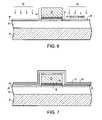
- FIG. 7is a pictorial representation (through a cross sectional view) illustrating the structure of FIG. 6 after forming optional first and second dielectric layers.
- FIG. 8is a pictorial representation (through a cross sectional view) illustrating the structure of FIG. 7 after the second dielectric layer has been selectively etched.
- FIG. 9is a pictorial representation (though a cross sectional view) illustrating the structure of FIG. 8 after the first dielectric layer has been selectively etched.
- FIG. 10is a pictorial representation (through a cross sectional view) illustrating the structure of FIG. 9 after performing an optional step in which a metal compound is formed over the optionally doped portion of the layer of at least one one-dimensional nanostructure.
- FIG. 11is a pictorial-representation (through a cross-sectional view) illustrating the structure of FIG. 9 after forming a source/drain metal layer thereon.
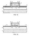
- FIG. 12is a pictorial representation (through a cross sectional view) illustrating the structure of FIG. 11 after performing a carbide annealing step.
- FIG. 13is a pictorial representation (through a cross sectional view) illustrating the structure of FIG. 12 after etching away excess source/drain metal.
- FIG. 14is a pictorial representation (through a cross sectional view) illustrating a structure similar to that shown in FIG. 13 except that the initial substrate shown in FIG. 1B was employed.
- the present inventionwhich provides a one-dimensional nanostructure-containing FET and a method of fabricating the same, will now be described in greater detail by referring to the drawings that accompany the present application.
- the various drawings of the present inventionare provided for illustrative purposes and thus they are not drawn to scale.
- the drawingsdepict the presence of a single gate region; the term “gate region” is used herein to denote the gate, gate electrode and underlying device channel. Although a single gate region is depicted and described, the present invention also contemplates forming a plurality of such gate regions and thus a plurality of one-dimensional nanostructure-containing FETs on a surface of a substrate.
- the present inventionbegins with first providing the initial substrate shown in either FIG. 1A or FIG. 1B .
- the initial substrate 10 A shown in FIG. 1Acomprises a semiconductor layer 12 which includes a dielectric layer 14 thereon.
- the semiconductor layer 12includes any type of semiconducting material including, but not limited to: Si, SiGe, SiC, SiGeC, GaAs, InAs, InP or any other III/V or II/VI compound semiconductor.
- the semiconductor layer 12may also comprise a layered semiconductor such as, for example, Si/SiGe or Si/SiGeC.
- the semiconductor layer 12may comprise a silicon-on-insulator (SOI) or a silicon germanium-on-insulator (SGOI).
- the semiconductor layer 12can be undoped or doped with one or more doping regions at this point of the present invention. Also, the semiconductor layer 12 may be strained or unstrained and it may have any crystallographic orientation including, for example, (111), (110) or (100). Also, the semiconducting substrate 12 can be used either for a back gate or for building other devices nearby (on the same chip or not) with conventional techniques.
- the semiconductor layer 12when the dielectric layer 14 is thick, the semiconductor layer 12 may be replaced with a handling substrate such as a metal or glass.
- a handling substratesuch as a metal or glass.
- the present inventionalso contemplates embodiments when the entire substrate is comprised of the dielectric layer 14 .
- the dielectric layer 14may comprise an oxide, a nitride, an oxynitride, a carbon containing dielectric such as, diamond like carbon (DLC) or fluorinated DLC, a high k dielectric (k greater than 4.0, typically greater than 7.0), an organic dielectric or multilayers thereof.
- the dielectric layer 14comprises an oxide such as SiO 2 or a nitride such as Si 3 N 4 .
- the dielectric layer 14comprises a DLC layer.
- the dielectric layer 14 shown in FIG. 1Ais formed on the surface of the semiconductor layer 12 utilizing a conventional deposition process such as, for example, chemical vapor deposition (CVD), plasma-enhanced chemical vapor deposition (PECVD), chemical solution deposition, sputtering, atomic layer deposition (ALD), physical vapor deposition (PVP), spin-on coating, epitaxial growth and other like deposition processing.
- CVDchemical vapor deposition
- PECVDplasma-enhanced chemical vapor deposition
- ALDatomic layer deposition
- PVPphysical vapor deposition
- spin-on coatingepitaxial growth and other like deposition processing.
- the dielectric layer 14can also be formed by thermal oxidation, nitridation or oxynitridation.
- the thickness of the dielectric layer 14 formed atop the semiconductor layer 12may vary depending on the type of dielectric material employed as well as the technique that was used to form the same. Typically, the dielectric layer. 14 has a thickness from about a fraction of a nanometer to about 500 nm, with a thickness from about 1 to about 10 nm being more typical. The aforementioned ranges are for semiconductor substrates and for back gate processes. For substrates without electrical functionality, the whole substrate can be a dielectric or the dielectric thickness can be extremely thick.
- FIG. 1Bshows another substrate 10 B that can be used in the present invention.
- the initial substrate 10 B shown in FIG. 1Bincludes a semiconductor layer 12 , a dielectric layer 14 , and regions of a C-containing compound 16 embedded within the dielectric layer 14 .
- the C-containing compound 16can be any compound material that includes C such as, for example, DLC, or fluorinated DLC.
- the C-containing compound 16is formed by blanket depositing the dielectric layer 14 on the surface of the semiconductor layer 12 , forming a patterned photoresist (not shown) on the surface of the dielectric layer 14 and etching an opening into the dielectric layer 14 which defines the area for the embedded C-containing compound 16 .
- the patterned photoresistis formed by conventional processing including applying a photoresist to the surface of the dielectric layer 14 , exposing the photoresist to a pattern of radiation and developing the exposed photoresist utilizing a conventional resist developer.
- the etching stepwhich forms an opening into the dielectric layer 14 , includes a dry etching process such as reactive-ion etching, ion beam etching, plasma etching or laser ablation. In addition to dry etching, the present invention also contemplates using a wet etch to provide the openings for forming the embedded regions within the dielectric layer 14 .
- the C-containing compound 16is deposited forming the structure shown, for example, in FIG. 1B .
- the depth of the C-containing compound 16 formed into the dielectric layer 14is from about 1 nm to about 500 nm or more, with a depth from about 5 to about 20 nm being more typical.
- initial substrate 10 Autilizes the description that follows.
- initial substrate 10 Ais specifically utilized, the present invention and the following processing steps work equally well for the alternative initial substrate 10 B shown in FIG. 1B or with a non-semiconducting substrate.
- a layer of at least one one-dimensional nanostructure 18is formed atop the dielectric layer 14 ; in the case in which initial substrate 10 B is utilized, the layer of at least one one-dimensional nanostructure 18 is formed atop the surfaces of both the dielectric layer 14 and the embedded C-containing compound 16 .
- the layer of at least one one-dimensional nanostructure 18may include a nanotube, a nanowire or a combination of these two types of nanomaterials.
- nanotubesdiffer from nanowires because nanotubes typically have a hollow cavity, whereas nanowires are completely filled nanomaterials.
- One-dimensional nanostructuresare structures with nanometer-sized diameters and much, much longer lengths. In other words, the structures have a high aspect ratio and quantum effects become important for these systems.
- the layer of at least one one-dimensional nanostructure 18comprises nanotubes, while in another highly preferred embodiment of the present invention the layer of at least one one-dimensional nanostructure 18 comprises nanowires.
- the nanotubes that can be used in the present inventionare single walled or multi-walled nanomaterials that have an outer diameter that is typically from about 0.4 nm to about 30 nm, with an outer diameter from about 0.8 nm to about 2.5 nm being more typical, and a length that is typically from about 5 nm to about 100 ⁇ m, with a length from about 10 nm to about 10 ⁇ m being more typical.
- the nanotubes that can be used in the present inventionhave an inner diameter that is typically from about 0.4 nm to about 15 nm, with an inner diameter from about 0.8 nm to about 2.5 nm being more highly typical.
- the nanotubes useful in the present inventionare further characterized as having a high aspect ratio that is typically on the order of about 5 or greater, with an aspect ratio from about 5 to about 5000 being more typical.
- the nanowires that can be used in the present inventioncomprise various atomic layers, i.e., more than one shell, in which the outer diameter is typically from about 0.4 nm to about 100 nm, with an outer diameter from about 0.8 nm to about 50 nm being more typical, and a length that is from about 5 nm to about 100 ⁇ m, with a length from about 10 nm to about 10 ⁇ m being more typical.
- the nanowires useful in the present inventionare further characterized as having a high aspect ratio that is typically on the order of about 5 or greater, with an aspect ratio from about 5 to about 5000 being more typical.
- the layer of at least one one-dimensional nanostructure 18 employed in the present inventiontypically includes a C-based nanomaterial that has a hexagonal lattice structure that is rolled up. That is, the nanostructures of the present invention typically are comprised of carbon, e.g., graphite. Although C-based nanomaterials are preferably used, the present invention also contemplates other types of nanomaterials such as metallic or a combination of C-based and metallic.
- the thickness of the layer of at least one one-dimensional nanostructure 18 formed at this point of the present inventioncan vary depending on the technique that was used to form the same. Typically, the layer of at least one one-dimensional nanostructure 18 has a thickness from about 0.4 to about 500 nm, with a thickness from about 0.8 to about 50 nm being more typical. In embodiments in which nanotubes are used, the layer of nanotubes 18 typically has a thickness from about 0.8 to about 3 nm.
- layer of at least one one-dimensional nanostructureis used herein to denote a layer that includes at least one nanotube or nanowire as well a layer that contains a controlled and selected number of such one-dimensional nanostructures.
- layer 18includes a plurality of one-dimensional nanostructures thus the remaining text uses the phrase “layer of one-dimensional nanostructures”.
- the layer of dimensional nanostructures 18can be formed utilizing techniques that are well known in the art.
- carbon-based nanotubescan be produced by arc-discharge and laser ablation of a carbon target.
- carbon-based nanotubescan be made by chemical vapor deposition in the presence of metallic particles.
- Specific process details for nanotube formationthat can be used in the present invention can be found, for example, in S. Iijima, et al. “Helical Microtubes of Graphite Carbon”, Nature 354, 56 (1991); D. S. Bethune, et al. “Cobalt Catalyzed Growth of Carbon Nanotubes with Single-Atomic-Layer Walls” Nature 363, 605 (1993), and R. Saito, et al.
- the layer of carbon nanotubes 18is formed by chemical vapor deposition at 900° C. for 10 mm using Fe catalyst particles.
- Carbon-based nanowirescan also be produced by arc-discharge and laser ablation of a carbon target.
- carbon-based nanowirescan be made by chemical vapor deposition in the presence of metallic particles. Specific process details for nanowire formation that can be used in the present invention can be found, for example, in S. Botti, et al., Chemical Physics Letters vol. 355, no. 5-6: 395-9, 8 Apr. 2002; the entire content of which is incorporated herein by reference.
- the layer of carbon nanowires 18is formed utilizing laser-induced chemical vapor deposited amorphous hydrogenated carbon nanoparticles (from a mixture of ethylene and acetylene) as precursor (see, for example, S.
- the present inventionalso contemplates other techniques that are capable of forming such nanostructures.
- solution-phase decomposition, sol-gel electrophoresis, or wet-chemical, hydrothermal synthesiscan be used in forming one-dimensional nanostructures.
- a gate dielectric 20is formed on the surface of layer 18 ; See FIG. 3 .
- the gate dielectric 20can be formed by a thermal growing process such as, for example, oxidation, nitridation or oxynitridation.
- the gate dielectric 20can be formed by a deposition process such as, for example, chemical vapor deposition (CVD), plasma-assisted CVD, atomic layer deposition (ALD), evaporation, reactive sputtering, chemical solution deposition or other like deposition processes.
- the gate dielectric 20may also be formed utilizing any combination of the above processes.
- the gate dielectric 20is comprised of an insulating material including, but not limited to: an oxide, nitride, oxynitride and/or silicate including metal silicates and nitrided metal silicates. In one embodiment, it is preferred that the gate dielectric 20 is comprised of an oxide such as, for example, SiO 2 , HfO 2 , ZrO 2 , Al 2 O 3 , TiO 2 , La 2 O 3 , SrTiO 3 , LaAlO 3 or mixtures thereof.
- the physical thickness of the gate dielectric 20may vary, but typically, the gate dielectric 20 has a thickness from about 0.5 to about 100 nm, with a thickness from about 0.5 to about 10 nm being more typical.
- a blanket layer of a gate electrode 22is formed on the gate dielectric 20 utilizing a known deposition process such as, for example, physical vapor deposition, CVD or evaporation.
- the thickness, i.e., height, of the gate electrode 22 deposited at this point of the present inventionmay vary-depending on the deposition process employed.
- the gate electrode 22has a vertical thickness from about 5 to about 180 nm, with a thickness from about 5 to about 50 nm being more typical.
- the gate electrode 22can comprise any conductive material that is typically employed as a gate of a CMOS structure.
- conductive materialsthat can be employed as the gate electrode 22 include, but are not limited to: polysilicon, conductive metals, conductive metal alloys, conductive silicides, conductive nitrides, polySiGe or combinations thereof, including multilayers thereof.
- a gate cap comprised of an oxide or nitridecan be formed atop the gate electrode 22 . Also, it is possible to form a barrier layer between multiple layers of gate electrode materials.
- the blanket layer of gate electrode 22is then patterned providing the structure shown in FIG. 3 .
- Patterning of the blanket layer of gate electrode 22can be achieved utilizing conventional techniques that are well known in the art.
- patterning of the gate electrode 22can be performed by lithography and etching.
- the lithographic stepincludes applying a photoresist (not shown) to the upper surface of the gate electrode 22 (or optional gate cap, if present), exposing the photoresist to a desired pattern of radiation and developing the exposed photoresist utilizing a conventional resist developer.
- the pattern in the photoresistis then transferred to the blanket layer of gate electrode 22 (or optional gate cap first and then gate electrode 22 ) utilizing one or more etching steps.
- the etchingincludes a dry etching process, such as reactive ion etching, ion beam etching, plasma etching or laser ablation. Wet etching can also be used to pattern the gate electrode 22 . As shown, the etching step selectively etches portions of the gate electrode 22 , stopping atop the gate dielectric 20 . The patterned photoresist is typically removed after the pattern has been transferred into the gate dielectric 20 utilizing a conventional stripping process.
- the dimensions of the gate formedcan vary from about 3 nm to several micrometers, preferably between 7 nm and 1 ⁇ m.
- the layer of the at least one one-dimensional nanostructure 18 and the gate dielectric 20are located interposed between the substrate 12 and the gate electrode 22 .
- FIG. 4illustrates a structure similar to that shown in FIG. 3 except that the initial substrate used is the one illustrated in FIG. 1B and alignment marks 100 and/or 101 are utilized.
- the alignment mark 100is formed into the substrate, while the alignment mark 101 is formed atop the surface of the gate dielectric 20 .
- the alignments marks 100 and 101are formed utilizing a conventional process well known in the art and they serve to align the gate level to the underlying substrate.
- FIG. 5shows the structure after the exposed regions of gate dielectric 20 , not including the patterned gate electrode 22 (and gate cap, if present), are removed.
- the removal of the exposed portion of the gate dielectric 20is performed utilizing an etching process that selectively removes gate dielectric material as compared with a gate conductor and/or the layer of one-dimensional nanostructures 18 . Dry etching or wet etching is contemplated herein for selectively removing the exposed portions of the gate dielectric 20 . As illustrated, this removal steps exposes a portion of the layer 18 that is adjacent to the gate stack 24 .
- Gate stack 24includes at least the patterned gate electrode 22 and the patterned gate dielectric 20 . Although a single gate stack 24 is shown, a plurality of such gate stacks can be formed as described above.
- the exposed portion of layer 18is then optionally doped with a first conductivity type dopant 26 (either n-type or p-type) to provide an optional dopant region 28 .
- a first conductivity type dopant 26either n-type or p-type
- the doping of the exposed portion of layer 18is optional and is not used in all instances.
- the dopingcan be performed by electrostatic doping, gas phase doping or other like doping techniques. Ion implantation can be used if the layer of one-dimensional nanostructures 18 includes nanowires.
- the dopant 26can be an n-type dopant which includes at least one element from Group VA of the Periodic Table of Elements, or the dopant 26 can be a p-type dopant that includes at least one element from Group IIIA of the Periodic Table of Elements.
- the dopingprovides dopant region 28 which typically has a doping concentration from about 10 19 to about 10 22 atoms/cm 3 . More typically, the dopant region 28 , which is located in the exposed portion of layer 18 , has a dopant concentration from about 10 21 to about 10 22 atoms/cm 3 .
- dielectric stack 29comprising one or more dielectric layers is optionally formed. It is noted that the dielectric stack 29 is used to provide spacers on the sidewalls of the gate stack 24 . In some embodiments where a self-aligned anneal is used, spacer formation is required. In yet other embodiments where a non self-aligned anneal is used, spacer formation is not required.
- the dopant implantation stepcan occur prior to formation of the spacers or after formation of one of the spacers and after formation of the other spacer.
- dielectric stack 29includes a first dielectric layer 30 and a second dielectric layer 32 .
- the dielectric stack 29comprises a dielectric material such as, for example, an oxide, nitride, or oxynitride.
- a conventional deposition processsuch as described for the formation of the gate dielectric 20 can be employed in forming the dielectric stack 29 .
- the dielectric stack 29is formed by a thermal process.
- the thickness of the dielectric stack 29may vary, but typically the overall thickness of the dielectric stack 29 is from about 5 to about 100 nm.
- the dielectric stack 29 and subsequent spacer formationcan occur prior to the optional doping step mentioned above.
- the dielectric stack 29includes a first dielectric (i.e., inner spacer material) 30 and a second dielectric (i.e., outer spacer material) 32 which are composed of different dielectric materials.
- first dielectric 30is comprised of a nitride such as silicon nitride and second dielectric 32 is comprised of an oxide such as silicon dioxide.
- Etchingis then performed to remove the dielectric stack 29 from all horizontal surfaces that were previously covered during deposition.
- the etchingis shown in FIGS. 8 and 9 .
- dry etching, wet etching or a combination thereofis used.
- a first etchis used to selectively remove the second dielectric 32 from horizontal surfaces of the structures (See FIG. 8 ), and then a second etch is used to remove the first dielectric 30 from horizontal surfaces of the structure.
- the resultant structure including inner spacer 30 ′ and outer spacer 32 ′is shown in FIG. 9 .
- the present inventioncontemplates a single spacer or multiple spacers located on the sidewall of the gate stack 24 .
- a layer of metal compound 34is formed atop the dopant region 28 that was previously formed into the layer of one-dimensional nanostructures 18 .
- the layer of metal compound 34can also be formed atop the exposed and undoped portion of layer 18 .
- the layer of the metal compound 34functionalizes the dopant region 28 (or alternatively the exposed and undoped portion of layer 18 ) and aids in the formation of metal carbide regions.
- the layer of the metal compound 34comprises, for example, c-C 4 H 6 ⁇ Mo ⁇ O (where c stands for cyclic) such as described in H.
- the layer of metal compound 34can be deposited selectively such that it reacts chemically with the layer of one-dimensional nanostructures. When a selective deposition is employed, the layer 34 can go underneath the sidewalls if undercutting occurs (this occurs in instances in which a non-directional etch is used). In some embodiments, a mask level (formed by reactive-ion etching or liftoff) is used during the deposition of layer 34 such that the layer 34 does not extend beneath the sidewalls. The thickness of the layer of the metal compound 34 may vary depending on the complex used as well as the technique that was used to form the same.
- a source/drain metal 36is formed at least atop the exposed dopant region 28 that was previously formed into portions of layer 18 as shown in FIG. 11 .
- source/drain metal 36is formed at least atop the layer of metal compound 34 shown in FIG. 10 .
- the source/drain metal 36is formed on at least exposed and undoped portions of layer 18 .
- Source/drain metal 36is formed in the present invention utilizing a conformal deposition process, such as, for example, CVD, PECVD, chemical solution deposition, ALD, sputtering, plating, evaporation or other like processes.
- the source/drain metal 36is deposited from a carbon-containing target/source.
- the source/drain metal 36is deposited by ALD to increase the current injection areas from metal to nanostructure.
- ALDprovides a method to provide a uniform coverage of source/drain metal 36 around the circumference of each nanostructure. That is, a sleeve of the source/drain metal 36 can be formed around each of the nanostructures within layer 18 .
- the source/drain metal 36comprises any metal or metal-like element that can react with carbon to form a stable binary metal carbide phase.
- the source/drain metalmay include C and optionally other elements.
- Examples of such source/drain metalsinclude: Al, Si, Sc, Ti, V, Cr, Mn, Fe, Y, Zr, Nb, Mo, Hf, Ta, W and mixtures or alloys thereof.
- at least one of Al, Ti, Cr, Mo, W, Zr, Hf or Tais used as the source/drain metal 36 .
- the compound formationcan be performed in different atmospheres such as, for example, nitrogen, forming gas, chloride, bromide, fluoride, oxygen and others. The variation of ambient gases allows for the formation of different conductive compounds either containing the C from the nanotube or embedding the nanotube itself.
- the thickness of the source/drain metal 36may vary depending on the metal used as well as the technique that was used to form the same. Typically, the thickness of layer 36 is from about 3 to about 200 nm, with a thickness from about 5 to about 20 nm being more typical.
- the structure containing the sameis then subjected to an annealing step that is performed under conditions that cause reaction of the source/drain metal 36 with dopant region 28 containing the nano structures.
- the resultant structure that is formed after the anneal has been performedis shown in FIG. 12 .
- a metal-carbide region 38forms adjacent to the gate stack 24 ; the metal-carbide region 38 is aligned to an edge of the gate stack 24 as well as aligned abutting, but not overlapping, a sidewall, including a sidewall edge, of the remaining layer of one-dimensional nanostructures 18 / 28 .
- the remaining layer of one-dimensional nanostructures 18serves as the device channel.
- the annealing stepmay leave some of the source/drain metal 36 on the structure.
- the annealcauses a reaction between the source/drain metal 36 and an exposed and undoped portion of layer 18 .
- This embodimentwould also produce a metal-carbide region.
- the annealcauses a reaction between the source/drain metal 36 , optionally the layer of metal compound 34 and doped or undoped portions of layer 18 .
- the anneal stepcauses embedding of one-dimensional nanostructures in a conducting compound region that is generated by reaction of metal and the underlying substrate including C or oxide. When embedding occurs, the spacer needs to be comprised of a nitride so that the etch selectivity is not lost.
- the annealing step used at this point of the present invention to cause metal carbide 38 formationis performed at a temperature of about 600° C. or greater.
- the metal-carbide formation annealis performed at a temperature from about 750° to about 1100° C.
- the metal-carbide formation annealis performed in an inert ambient such as He, Ar, Ne, Kr, Xe, N 2 or mixtures thereof such as He—Ar.
- the annealis performed for a time period of sub-milliseconds or greater, with an annealing time from about 10 sec to about 30 min being more typical.
- the very short time annealare achieved using laser annealing.
- the annealingcan be performed utilizing a single annealing temperature or multiple annealing temperatures can be used.
- the annealingmay also include various ramp-up cycles, soak cycles, and cool down cycles, as desired.
- FIG. 13shows one possible structure that can be formed utilizing the above processing steps.
- FIG. 14shows another possible structure that can be formed; FIG. 14 differs from FIG. 13 in terms of the type of initial substrate used.
- a semiconductor structureis illustrated that includes a substrate 10 A or 10 B comprises at least one gate region located thereon.
- the at least one gate regioncomprises a patterned gate stack as well as the remaining layer of one-dimensional nanostructures 18 .
- a metal carbide contact, i.e., region 38is located on a surface of the substrate and it is aligned to an edge of the least one gate region as well as the remaining layer of one-dimensional nanostructures 18 .
Landscapes
- Engineering & Computer Science (AREA)
- Chemical & Material Sciences (AREA)
- Nanotechnology (AREA)
- Materials Engineering (AREA)
- Physics & Mathematics (AREA)
- Mathematical Physics (AREA)
- Theoretical Computer Science (AREA)
- Crystallography & Structural Chemistry (AREA)
- Thin Film Transistor (AREA)
- Electrodes Of Semiconductors (AREA)
- Insulated Gate Type Field-Effect Transistor (AREA)
- Carbon And Carbon Compounds (AREA)
Abstract
Description
Claims (15)
Priority Applications (10)
| Application Number | Priority Date | Filing Date | Title |
|---|---|---|---|
| US11/031,168US7598516B2 (en) | 2005-01-07 | 2005-01-07 | Self-aligned process for nanotube/nanowire FETs |
| PCT/EP2005/056746WO2006072538A1 (en) | 2005-01-07 | 2005-12-13 | Self-aligned process for nanotube/nanowire fets |
| EP05848927.9AEP1839346B1 (en) | 2005-01-07 | 2005-12-13 | Self-aligned process for nanotube/nanowire fets |
| CN2005800459257ACN101099248B (en) | 2005-01-07 | 2005-12-13 | Self-alignment method for nanotube/nanowire FETs |
| KR1020077015390AKR101033445B1 (en) | 2005-01-07 | 2005-12-13 | Self Alignment Process of Nanotube / Nanowire Field Effect Transistors |
| JP2007549844AJP5132320B2 (en) | 2005-01-07 | 2005-12-13 | Self-aligned process for nanotube / nanowire FETs |
| TW095100291ATWI463654B (en) | 2005-01-07 | 2006-01-04 | Self-aligned process of nano tube/nano wire field effect transistor |
| US11/866,627US20080026534A1 (en) | 2005-01-07 | 2007-10-03 | SELF-ALIGNED PROCESS FOR NANOTUBE/NANOWIRE FETs |
| US12/125,501US8003453B2 (en) | 2005-01-07 | 2008-05-22 | Self-aligned process for nanotube/nanowire FETs |
| US13/153,051US8119466B2 (en) | 2005-01-07 | 2011-06-03 | Self-aligned process for nanotube/nanowire FETs |
Applications Claiming Priority (1)
| Application Number | Priority Date | Filing Date | Title |
|---|---|---|---|
| US11/031,168US7598516B2 (en) | 2005-01-07 | 2005-01-07 | Self-aligned process for nanotube/nanowire FETs |
Related Child Applications (1)
| Application Number | Title | Priority Date | Filing Date |
|---|---|---|---|
| US11/866,627DivisionUS20080026534A1 (en) | 2005-01-07 | 2007-10-03 | SELF-ALIGNED PROCESS FOR NANOTUBE/NANOWIRE FETs |
Publications (2)
| Publication Number | Publication Date |
|---|---|
| US20060151844A1 US20060151844A1 (en) | 2006-07-13 |
| US7598516B2true US7598516B2 (en) | 2009-10-06 |
Family
ID=36095653
Family Applications (4)
| Application Number | Title | Priority Date | Filing Date |
|---|---|---|---|
| US11/031,168Expired - Fee RelatedUS7598516B2 (en) | 2005-01-07 | 2005-01-07 | Self-aligned process for nanotube/nanowire FETs |
| US11/866,627AbandonedUS20080026534A1 (en) | 2005-01-07 | 2007-10-03 | SELF-ALIGNED PROCESS FOR NANOTUBE/NANOWIRE FETs |
| US12/125,501Expired - LifetimeUS8003453B2 (en) | 2005-01-07 | 2008-05-22 | Self-aligned process for nanotube/nanowire FETs |
| US13/153,051Expired - LifetimeUS8119466B2 (en) | 2005-01-07 | 2011-06-03 | Self-aligned process for nanotube/nanowire FETs |
Family Applications After (3)
| Application Number | Title | Priority Date | Filing Date |
|---|---|---|---|
| US11/866,627AbandonedUS20080026534A1 (en) | 2005-01-07 | 2007-10-03 | SELF-ALIGNED PROCESS FOR NANOTUBE/NANOWIRE FETs |
| US12/125,501Expired - LifetimeUS8003453B2 (en) | 2005-01-07 | 2008-05-22 | Self-aligned process for nanotube/nanowire FETs |
| US13/153,051Expired - LifetimeUS8119466B2 (en) | 2005-01-07 | 2011-06-03 | Self-aligned process for nanotube/nanowire FETs |
Country Status (7)
| Country | Link |
|---|---|
| US (4) | US7598516B2 (en) |
| EP (1) | EP1839346B1 (en) |
| JP (1) | JP5132320B2 (en) |
| KR (1) | KR101033445B1 (en) |
| CN (1) | CN101099248B (en) |
| TW (1) | TWI463654B (en) |
| WO (1) | WO2006072538A1 (en) |
Cited By (14)
| Publication number | Priority date | Publication date | Assignee | Title |
|---|---|---|---|---|
| US20110127493A1 (en)* | 2009-11-30 | 2011-06-02 | International Business Machines Corporation | Self aligned carbide source/drain fet |
| US20110127492A1 (en)* | 2009-11-30 | 2011-06-02 | International Business Machines Corporation | Field Effect Transistor Having Nanostructure Channel |
| US8513099B2 (en) | 2010-06-17 | 2013-08-20 | International Business Machines Corporation | Epitaxial source/drain contacts self-aligned to gates for deposited FET channels |
| US8580624B2 (en) | 2011-11-01 | 2013-11-12 | International Business Machines Corporation | Nanowire FET and finFET hybrid technology |
| DE112012000467B4 (en)* | 2011-01-13 | 2015-01-08 | International Business Machines Corporation | Radiation-resistant transistor based on graphene and carbon nanotubes and method for its production |
| US9299939B1 (en) | 2014-12-09 | 2016-03-29 | International Business Machines Corporation | Formation of CMOS device using carbon nanotubes |
| US9368599B2 (en) | 2010-06-22 | 2016-06-14 | International Business Machines Corporation | Graphene/nanostructure FET with self-aligned contact and gate |
| US9543535B1 (en) | 2015-06-29 | 2017-01-10 | International Business Machines Corporation | Self-aligned carbon nanotube transistor including source/drain extensions and top gate |
| US10319926B2 (en) | 2015-11-05 | 2019-06-11 | International Business Machines Corporation | End-bonded metal contacts on carbon nanotubes |
| US10333088B1 (en) | 2017-12-12 | 2019-06-25 | International Business Machines Corporation | Carbon nanotube transistor with carrier blocking using thin dielectric under contact |
| US10396300B2 (en) | 2015-12-03 | 2019-08-27 | International Business Machines Corporation | Carbon nanotube device with N-type end-bonded metal contacts |
| US10410931B2 (en) | 2017-01-09 | 2019-09-10 | Samsung Electronics Co., Ltd. | Fabricating method of nanosheet transistor spacer including inner spacer |
| US10665799B2 (en) | 2016-07-14 | 2020-05-26 | International Business Machines Corporation | N-type end-bonded metal contacts for carbon nanotube transistors |
| US10665798B2 (en) | 2016-07-14 | 2020-05-26 | International Business Machines Corporation | Carbon nanotube transistor and logic with end-bonded metal contacts |
Families Citing this family (438)
| Publication number | Priority date | Publication date | Assignee | Title |
|---|---|---|---|---|
| US6723299B1 (en) | 2001-05-17 | 2004-04-20 | Zyvex Corporation | System and method for manipulating nanotubes |
| US6905667B1 (en) | 2002-05-02 | 2005-06-14 | Zyvex Corporation | Polymer and method for using the polymer for noncovalently functionalizing nanotubes |
| US20040034177A1 (en) | 2002-05-02 | 2004-02-19 | Jian Chen | Polymer and method for using the polymer for solubilizing nanotubes |
| GB2421506B (en) | 2003-05-22 | 2008-07-09 | Zyvex Corp | Nanocomposites and methods thereto |
| FR2868209B1 (en)* | 2004-03-25 | 2006-06-16 | Commissariat Energie Atomique | FIELD-FIELD FIELD EFFECT TRANSISTOR DIAMOND CARBON |
| US7296576B2 (en) | 2004-08-18 | 2007-11-20 | Zyvex Performance Materials, Llc | Polymers for enhanced solubility of nanomaterials, compositions and methods therefor |
| US7687841B2 (en)* | 2005-08-02 | 2010-03-30 | Micron Technology, Inc. | Scalable high performance carbon nanotube field effect transistor |
| US7452759B2 (en)* | 2005-11-29 | 2008-11-18 | Micron Technology, Inc. | Carbon nanotube field effect transistor and methods for making same |
| US7919400B2 (en)* | 2007-07-10 | 2011-04-05 | Stion Corporation | Methods for doping nanostructured materials and nanostructured thin films |
| US8598569B2 (en) | 2008-04-30 | 2013-12-03 | International Business Machines Corporation | Pentacene-carbon nanotube composite, method of forming the composite, and semiconductor device including the composite |
| US8138102B2 (en)* | 2008-08-21 | 2012-03-20 | International Business Machines Corporation | Method of placing a semiconducting nanostructure and semiconductor device including the semiconducting nanostructure |
| US10378106B2 (en) | 2008-11-14 | 2019-08-13 | Asm Ip Holding B.V. | Method of forming insulation film by modified PEALD |
| TWI437106B (en)* | 2008-12-03 | 2014-05-11 | Tatung Co | One dimension nano magnetic wires and manufacturing method thereof |
| US8013324B2 (en)* | 2009-04-03 | 2011-09-06 | International Business Machines Corporation | Structurally stabilized semiconductor nanowire |
| US7902541B2 (en)* | 2009-04-03 | 2011-03-08 | International Business Machines Corporation | Semiconductor nanowire with built-in stress |
| US7943530B2 (en)* | 2009-04-03 | 2011-05-17 | International Business Machines Corporation | Semiconductor nanowires having mobility-optimized orientations |
| US8237150B2 (en)* | 2009-04-03 | 2012-08-07 | International Business Machines Corporation | Nanowire devices for enhancing mobility through stress engineering |
| US9394608B2 (en) | 2009-04-06 | 2016-07-19 | Asm America, Inc. | Semiconductor processing reactor and components thereof |
| US8108802B2 (en) | 2009-04-29 | 2012-01-31 | International Business Machines Corporation | Method for forming arbitrary lithographic wavefronts using standard mask technology |
| US20110012177A1 (en)* | 2009-07-20 | 2011-01-20 | International Business Machines Corporation | Nanostructure For Changing Electric Mobility |
| US8368125B2 (en) | 2009-07-20 | 2013-02-05 | International Business Machines Corporation | Multiple orientation nanowires with gate stack stressors |
| US8802201B2 (en) | 2009-08-14 | 2014-08-12 | Asm America, Inc. | Systems and methods for thin-film deposition of metal oxides using excited nitrogen-oxygen species |
| US8106383B2 (en)* | 2009-11-13 | 2012-01-31 | International Business Machines Corporation | Self-aligned graphene transistor |
| US8143113B2 (en)* | 2009-12-04 | 2012-03-27 | International Business Machines Corporation | Omega shaped nanowire tunnel field effect transistors fabrication |
| US8129247B2 (en) | 2009-12-04 | 2012-03-06 | International Business Machines Corporation | Omega shaped nanowire field effect transistors |
| US8384065B2 (en)* | 2009-12-04 | 2013-02-26 | International Business Machines Corporation | Gate-all-around nanowire field effect transistors |
| US8097515B2 (en)* | 2009-12-04 | 2012-01-17 | International Business Machines Corporation | Self-aligned contacts for nanowire field effect transistors |
| US8455334B2 (en) | 2009-12-04 | 2013-06-04 | International Business Machines Corporation | Planar and nanowire field effect transistors |
| US8173993B2 (en)* | 2009-12-04 | 2012-05-08 | International Business Machines Corporation | Gate-all-around nanowire tunnel field effect transistors |
| KR101659815B1 (en)* | 2009-12-08 | 2016-09-27 | 삼성전자주식회사 | Carbon nanotube transistor array and Manufacturing Method of Carbon nanotube transistor |
| US8101474B2 (en)* | 2010-01-06 | 2012-01-24 | International Business Machines Corporation | Structure and method of forming buried-channel graphene field effect device |
| US8722492B2 (en) | 2010-01-08 | 2014-05-13 | International Business Machines Corporation | Nanowire pin tunnel field effect devices |
| US8263477B2 (en)* | 2010-01-08 | 2012-09-11 | International Business Machines Corporation | Structure for use in fabrication of PiN heterojunction TFET |
| US8324940B2 (en) | 2010-04-13 | 2012-12-04 | International Business Machines Corporation | Nanowire circuits in matched devices |
| US8361907B2 (en) | 2010-05-10 | 2013-01-29 | International Business Machines Corporation | Directionally etched nanowire field effect transistors |
| US8324030B2 (en) | 2010-05-12 | 2012-12-04 | International Business Machines Corporation | Nanowire tunnel field effect transistors |
| US8404539B2 (en)* | 2010-07-08 | 2013-03-26 | International Business Machines Corporation | Self-aligned contacts in carbon devices |
| US8697467B2 (en)* | 2010-07-26 | 2014-04-15 | The Regents Of The University Of California | Surface and gas phase doping of III-V semiconductors |
| US8835231B2 (en) | 2010-08-16 | 2014-09-16 | International Business Machines Corporation | Methods of forming contacts for nanowire field effect transistors |
| US8536563B2 (en) | 2010-09-17 | 2013-09-17 | International Business Machines Corporation | Nanowire field effect transistors |
| US9312155B2 (en) | 2011-06-06 | 2016-04-12 | Asm Japan K.K. | High-throughput semiconductor-processing apparatus equipped with multiple dual-chamber modules |
| US9793148B2 (en) | 2011-06-22 | 2017-10-17 | Asm Japan K.K. | Method for positioning wafers in multiple wafer transport |
| US10364496B2 (en) | 2011-06-27 | 2019-07-30 | Asm Ip Holding B.V. | Dual section module having shared and unshared mass flow controllers |
| US10854498B2 (en) | 2011-07-15 | 2020-12-01 | Asm Ip Holding B.V. | Wafer-supporting device and method for producing same |
| US20130023129A1 (en) | 2011-07-20 | 2013-01-24 | Asm America, Inc. | Pressure transmitter for a semiconductor processing environment |
| US8952355B2 (en) | 2011-09-29 | 2015-02-10 | Intel Corporation | Electropositive metal containing layers for semiconductor applications |
| US9017481B1 (en) | 2011-10-28 | 2015-04-28 | Asm America, Inc. | Process feed management for semiconductor substrate processing |
| US8946830B2 (en) | 2012-04-04 | 2015-02-03 | Asm Ip Holdings B.V. | Metal oxide protective layer for a semiconductor device |
| US9558931B2 (en) | 2012-07-27 | 2017-01-31 | Asm Ip Holding B.V. | System and method for gas-phase sulfur passivation of a semiconductor surface |
| US8741751B2 (en) | 2012-08-10 | 2014-06-03 | International Business Machines Corporation | Double contacts for carbon nanotubes thin film devices |
| US8741756B2 (en) | 2012-08-13 | 2014-06-03 | International Business Machines Corporation | Contacts-first self-aligned carbon nanotube transistor with gate-all-around |
| US9659799B2 (en) | 2012-08-28 | 2017-05-23 | Asm Ip Holding B.V. | Systems and methods for dynamic semiconductor process scheduling |
| US9021985B2 (en) | 2012-09-12 | 2015-05-05 | Asm Ip Holdings B.V. | Process gas management for an inductively-coupled plasma deposition reactor |
| US10714315B2 (en) | 2012-10-12 | 2020-07-14 | Asm Ip Holdings B.V. | Semiconductor reaction chamber showerhead |
| US8685817B1 (en)* | 2012-11-19 | 2014-04-01 | International Business Machines Corporation | Metal gate structures for CMOS transistor devices having reduced parasitic capacitance |
| US8796096B2 (en) | 2012-12-04 | 2014-08-05 | International Business Machines Corporation | Self-aligned double-gate graphene transistor |
| US8609481B1 (en) | 2012-12-05 | 2013-12-17 | International Business Machines Corporation | Gate-all-around carbon nanotube transistor with selectively doped spacers |
| US9640416B2 (en) | 2012-12-26 | 2017-05-02 | Asm Ip Holding B.V. | Single-and dual-chamber module-attachable wafer-handling chamber |
| US20160376700A1 (en) | 2013-02-01 | 2016-12-29 | Asm Ip Holding B.V. | System for treatment of deposition reactor |
| US9589770B2 (en) | 2013-03-08 | 2017-03-07 | Asm Ip Holding B.V. | Method and systems for in-situ formation of intermediate reactive species |
| US9484191B2 (en) | 2013-03-08 | 2016-11-01 | Asm Ip Holding B.V. | Pulsed remote plasma method and system |
| US8993054B2 (en) | 2013-07-12 | 2015-03-31 | Asm Ip Holding B.V. | Method and system to reduce outgassing in a reaction chamber |
| US9018111B2 (en) | 2013-07-22 | 2015-04-28 | Asm Ip Holding B.V. | Semiconductor reaction chamber with plasma capabilities |
| US9793115B2 (en) | 2013-08-14 | 2017-10-17 | Asm Ip Holding B.V. | Structures and devices including germanium-tin films and methods of forming same |
| US9240412B2 (en) | 2013-09-27 | 2016-01-19 | Asm Ip Holding B.V. | Semiconductor structure and device and methods of forming same using selective epitaxial process |
| US9556516B2 (en) | 2013-10-09 | 2017-01-31 | ASM IP Holding B.V | Method for forming Ti-containing film by PEALD using TDMAT or TDEAT |
| US9605343B2 (en)* | 2013-11-13 | 2017-03-28 | Asm Ip Holding B.V. | Method for forming conformal carbon films, structures conformal carbon film, and system of forming same |
| US10179947B2 (en) | 2013-11-26 | 2019-01-15 | Asm Ip Holding B.V. | Method for forming conformal nitrided, oxidized, or carbonized dielectric film by atomic layer deposition |
| US10683571B2 (en) | 2014-02-25 | 2020-06-16 | Asm Ip Holding B.V. | Gas supply manifold and method of supplying gases to chamber using same |
| US9447498B2 (en) | 2014-03-18 | 2016-09-20 | Asm Ip Holding B.V. | Method for performing uniform processing in gas system-sharing multiple reaction chambers |
| US10167557B2 (en) | 2014-03-18 | 2019-01-01 | Asm Ip Holding B.V. | Gas distribution system, reactor including the system, and methods of using the same |
| US11015245B2 (en) | 2014-03-19 | 2021-05-25 | Asm Ip Holding B.V. | Gas-phase reactor and system having exhaust plenum and components thereof |
| US9287516B2 (en) | 2014-04-07 | 2016-03-15 | International Business Machines Corporation | Forming pn junction contacts by different dielectrics |
| US10858737B2 (en) | 2014-07-28 | 2020-12-08 | Asm Ip Holding B.V. | Showerhead assembly and components thereof |
| US9543180B2 (en) | 2014-08-01 | 2017-01-10 | Asm Ip Holding B.V. | Apparatus and method for transporting wafers between wafer carrier and process tool under vacuum |
| US9890456B2 (en) | 2014-08-21 | 2018-02-13 | Asm Ip Holding B.V. | Method and system for in situ formation of gas-phase compounds |
| US10941490B2 (en) | 2014-10-07 | 2021-03-09 | Asm Ip Holding B.V. | Multiple temperature range susceptor, assembly, reactor and system including the susceptor, and methods of using the same |
| US9657845B2 (en) | 2014-10-07 | 2017-05-23 | Asm Ip Holding B.V. | Variable conductance gas distribution apparatus and method |
| KR102300403B1 (en) | 2014-11-19 | 2021-09-09 | 에이에스엠 아이피 홀딩 비.브이. | Method of depositing thin film |
| KR102263121B1 (en) | 2014-12-22 | 2021-06-09 | 에이에스엠 아이피 홀딩 비.브이. | Semiconductor device and manufacuring method thereof |
| US9478415B2 (en) | 2015-02-13 | 2016-10-25 | Asm Ip Holding B.V. | Method for forming film having low resistance and shallow junction depth |
| US10529542B2 (en) | 2015-03-11 | 2020-01-07 | Asm Ip Holdings B.V. | Cross-flow reactor and method |
| US10276355B2 (en) | 2015-03-12 | 2019-04-30 | Asm Ip Holding B.V. | Multi-zone reactor, system including the reactor, and method of using the same |
| US10458018B2 (en) | 2015-06-26 | 2019-10-29 | Asm Ip Holding B.V. | Structures including metal carbide material, devices including the structures, and methods of forming same |
| US10600673B2 (en) | 2015-07-07 | 2020-03-24 | Asm Ip Holding B.V. | Magnetic susceptor to baseplate seal |
| US10043661B2 (en) | 2015-07-13 | 2018-08-07 | Asm Ip Holding B.V. | Method for protecting layer by forming hydrocarbon-based extremely thin film |
| US9899291B2 (en) | 2015-07-13 | 2018-02-20 | Asm Ip Holding B.V. | Method for protecting layer by forming hydrocarbon-based extremely thin film |
| US9627330B2 (en)* | 2015-07-13 | 2017-04-18 | International Business Machines Corporation | Support for long channel length nanowire transistors |
| US10083836B2 (en) | 2015-07-24 | 2018-09-25 | Asm Ip Holding B.V. | Formation of boron-doped titanium metal films with high work function |
| US10087525B2 (en) | 2015-08-04 | 2018-10-02 | Asm Ip Holding B.V. | Variable gap hard stop design |
| US10403497B2 (en) | 2015-08-12 | 2019-09-03 | Shindengen Electric Manufacturing Co., Ltd. | Method of manufacturing silicon carbide semiconductor device and silicon carbide semiconductor device |
| US9647114B2 (en) | 2015-08-14 | 2017-05-09 | Asm Ip Holding B.V. | Methods of forming highly p-type doped germanium tin films and structures and devices including the films |
| US9711345B2 (en) | 2015-08-25 | 2017-07-18 | Asm Ip Holding B.V. | Method for forming aluminum nitride-based film by PEALD |
| US9960072B2 (en) | 2015-09-29 | 2018-05-01 | Asm Ip Holding B.V. | Variable adjustment for precise matching of multiple chamber cavity housings |
| US9909214B2 (en) | 2015-10-15 | 2018-03-06 | Asm Ip Holding B.V. | Method for depositing dielectric film in trenches by PEALD |
| US10211308B2 (en) | 2015-10-21 | 2019-02-19 | Asm Ip Holding B.V. | NbMC layers |
| US10322384B2 (en) | 2015-11-09 | 2019-06-18 | Asm Ip Holding B.V. | Counter flow mixer for process chamber |
| US9455138B1 (en) | 2015-11-10 | 2016-09-27 | Asm Ip Holding B.V. | Method for forming dielectric film in trenches by PEALD using H-containing gas |
| US9905420B2 (en) | 2015-12-01 | 2018-02-27 | Asm Ip Holding B.V. | Methods of forming silicon germanium tin films and structures and devices including the films |
| US9607837B1 (en) | 2015-12-21 | 2017-03-28 | Asm Ip Holding B.V. | Method for forming silicon oxide cap layer for solid state diffusion process |
| US9627221B1 (en) | 2015-12-28 | 2017-04-18 | Asm Ip Holding B.V. | Continuous process incorporating atomic layer etching |
| US9735024B2 (en) | 2015-12-28 | 2017-08-15 | Asm Ip Holding B.V. | Method of atomic layer etching using functional group-containing fluorocarbon |
| US11139308B2 (en) | 2015-12-29 | 2021-10-05 | Asm Ip Holding B.V. | Atomic layer deposition of III-V compounds to form V-NAND devices |
| US9698363B1 (en)* | 2015-12-30 | 2017-07-04 | International Business Machines Corporation | RF-transistors with self-aligned point contacts |
| US9754779B1 (en) | 2016-02-19 | 2017-09-05 | Asm Ip Holding B.V. | Method for forming silicon nitride film selectively on sidewalls or flat surfaces of trenches |
| US10529554B2 (en) | 2016-02-19 | 2020-01-07 | Asm Ip Holding B.V. | Method for forming silicon nitride film selectively on sidewalls or flat surfaces of trenches |
| US10468251B2 (en) | 2016-02-19 | 2019-11-05 | Asm Ip Holding B.V. | Method for forming spacers using silicon nitride film for spacer-defined multiple patterning |
| US10501866B2 (en) | 2016-03-09 | 2019-12-10 | Asm Ip Holding B.V. | Gas distribution apparatus for improved film uniformity in an epitaxial system |
| US10343920B2 (en) | 2016-03-18 | 2019-07-09 | Asm Ip Holding B.V. | Aligned carbon nanotubes |
| US9892913B2 (en) | 2016-03-24 | 2018-02-13 | Asm Ip Holding B.V. | Radial and thickness control via biased multi-port injection settings |
| WO2017171736A1 (en)* | 2016-03-30 | 2017-10-05 | Intel Corporation | Nanowire for transistor integration |
| US10865475B2 (en) | 2016-04-21 | 2020-12-15 | Asm Ip Holding B.V. | Deposition of metal borides and silicides |
| US10087522B2 (en) | 2016-04-21 | 2018-10-02 | Asm Ip Holding B.V. | Deposition of metal borides |
| US10190213B2 (en) | 2016-04-21 | 2019-01-29 | Asm Ip Holding B.V. | Deposition of metal borides |
| US10367080B2 (en) | 2016-05-02 | 2019-07-30 | Asm Ip Holding B.V. | Method of forming a germanium oxynitride film |
| US10032628B2 (en) | 2016-05-02 | 2018-07-24 | Asm Ip Holding B.V. | Source/drain performance through conformal solid state doping |
| KR102592471B1 (en) | 2016-05-17 | 2023-10-20 | 에이에스엠 아이피 홀딩 비.브이. | Method of forming metal interconnection and method of fabricating semiconductor device using the same |
| US11453943B2 (en) | 2016-05-25 | 2022-09-27 | Asm Ip Holding B.V. | Method for forming carbon-containing silicon/metal oxide or nitride film by ALD using silicon precursor and hydrocarbon precursor |
| US10388509B2 (en) | 2016-06-28 | 2019-08-20 | Asm Ip Holding B.V. | Formation of epitaxial layers via dislocation filtering |
| US9859151B1 (en) | 2016-07-08 | 2018-01-02 | Asm Ip Holding B.V. | Selective film deposition method to form air gaps |
| US10612137B2 (en) | 2016-07-08 | 2020-04-07 | Asm Ip Holdings B.V. | Organic reactants for atomic layer deposition |
| US9793135B1 (en) | 2016-07-14 | 2017-10-17 | ASM IP Holding B.V | Method of cyclic dry etching using etchant film |
| US10714385B2 (en) | 2016-07-19 | 2020-07-14 | Asm Ip Holding B.V. | Selective deposition of tungsten |
| KR102354490B1 (en) | 2016-07-27 | 2022-01-21 | 에이에스엠 아이피 홀딩 비.브이. | Method of processing a substrate |
| KR102532607B1 (en) | 2016-07-28 | 2023-05-15 | 에이에스엠 아이피 홀딩 비.브이. | Substrate processing apparatus and method of operating the same |
| US9812320B1 (en) | 2016-07-28 | 2017-11-07 | Asm Ip Holding B.V. | Method and apparatus for filling a gap |
| US10177025B2 (en) | 2016-07-28 | 2019-01-08 | Asm Ip Holding B.V. | Method and apparatus for filling a gap |
| US10395919B2 (en) | 2016-07-28 | 2019-08-27 | Asm Ip Holding B.V. | Method and apparatus for filling a gap |
| US9887082B1 (en) | 2016-07-28 | 2018-02-06 | Asm Ip Holding B.V. | Method and apparatus for filling a gap |
| US10090316B2 (en) | 2016-09-01 | 2018-10-02 | Asm Ip Holding B.V. | 3D stacked multilayer semiconductor memory using doped select transistor channel |
| US10410943B2 (en) | 2016-10-13 | 2019-09-10 | Asm Ip Holding B.V. | Method for passivating a surface of a semiconductor and related systems |
| US10643826B2 (en) | 2016-10-26 | 2020-05-05 | Asm Ip Holdings B.V. | Methods for thermally calibrating reaction chambers |
| US11532757B2 (en) | 2016-10-27 | 2022-12-20 | Asm Ip Holding B.V. | Deposition of charge trapping layers |
| US10714350B2 (en) | 2016-11-01 | 2020-07-14 | ASM IP Holdings, B.V. | Methods for forming a transition metal niobium nitride film on a substrate by atomic layer deposition and related semiconductor device structures |
| US10643904B2 (en) | 2016-11-01 | 2020-05-05 | Asm Ip Holdings B.V. | Methods for forming a semiconductor device and related semiconductor device structures |
| US10435790B2 (en) | 2016-11-01 | 2019-10-08 | Asm Ip Holding B.V. | Method of subatmospheric plasma-enhanced ALD using capacitively coupled electrodes with narrow gap |
| US10229833B2 (en) | 2016-11-01 | 2019-03-12 | Asm Ip Holding B.V. | Methods for forming a transition metal nitride film on a substrate by atomic layer deposition and related semiconductor device structures |
| US10134757B2 (en) | 2016-11-07 | 2018-11-20 | Asm Ip Holding B.V. | Method of processing a substrate and a device manufactured by using the method |
| KR102546317B1 (en) | 2016-11-15 | 2023-06-21 | 에이에스엠 아이피 홀딩 비.브이. | Gas supply unit and substrate processing apparatus including the same |
| US10340135B2 (en) | 2016-11-28 | 2019-07-02 | Asm Ip Holding B.V. | Method of topologically restricted plasma-enhanced cyclic deposition of silicon or metal nitride |
| KR102762543B1 (en) | 2016-12-14 | 2025-02-05 | 에이에스엠 아이피 홀딩 비.브이. | Substrate processing apparatus |
| US11581186B2 (en) | 2016-12-15 | 2023-02-14 | Asm Ip Holding B.V. | Sequential infiltration synthesis apparatus |
| US11447861B2 (en) | 2016-12-15 | 2022-09-20 | Asm Ip Holding B.V. | Sequential infiltration synthesis apparatus and a method of forming a patterned structure |
| US9916980B1 (en) | 2016-12-15 | 2018-03-13 | Asm Ip Holding B.V. | Method of forming a structure on a substrate |
| KR102700194B1 (en) | 2016-12-19 | 2024-08-28 | 에이에스엠 아이피 홀딩 비.브이. | Substrate processing apparatus |
| US10269558B2 (en) | 2016-12-22 | 2019-04-23 | Asm Ip Holding B.V. | Method of forming a structure on a substrate |
| US10867788B2 (en) | 2016-12-28 | 2020-12-15 | Asm Ip Holding B.V. | Method of forming a structure on a substrate |
| CN108269802B (en)* | 2017-01-04 | 2020-11-06 | 上海新昇半导体科技有限公司 | Carbon nano tube beam field effect transistor array and manufacturing method thereof |
| US11390950B2 (en) | 2017-01-10 | 2022-07-19 | Asm Ip Holding B.V. | Reactor system and method to reduce residue buildup during a film deposition process |
| US10655221B2 (en) | 2017-02-09 | 2020-05-19 | Asm Ip Holding B.V. | Method for depositing oxide film by thermal ALD and PEALD |
| US10468261B2 (en) | 2017-02-15 | 2019-11-05 | Asm Ip Holding B.V. | Methods for forming a metallic film on a substrate by cyclical deposition and related semiconductor device structures |
| US10283353B2 (en) | 2017-03-29 | 2019-05-07 | Asm Ip Holding B.V. | Method of reforming insulating film deposited on substrate with recess pattern |
| US10529563B2 (en) | 2017-03-29 | 2020-01-07 | Asm Ip Holdings B.V. | Method for forming doped metal oxide films on a substrate by cyclical deposition and related semiconductor device structures |
| US10103040B1 (en) | 2017-03-31 | 2018-10-16 | Asm Ip Holding B.V. | Apparatus and method for manufacturing a semiconductor device |
| USD830981S1 (en) | 2017-04-07 | 2018-10-16 | Asm Ip Holding B.V. | Susceptor for semiconductor substrate processing apparatus |
| KR102457289B1 (en) | 2017-04-25 | 2022-10-21 | 에이에스엠 아이피 홀딩 비.브이. | Method for depositing a thin film and manufacturing a semiconductor device |
| US10770286B2 (en) | 2017-05-08 | 2020-09-08 | Asm Ip Holdings B.V. | Methods for selectively forming a silicon nitride film on a substrate and related semiconductor device structures |
| US10446393B2 (en) | 2017-05-08 | 2019-10-15 | Asm Ip Holding B.V. | Methods for forming silicon-containing epitaxial layers and related semiconductor device structures |
| US10892156B2 (en) | 2017-05-08 | 2021-01-12 | Asm Ip Holding B.V. | Methods for forming a silicon nitride film on a substrate and related semiconductor device structures |
| US10504742B2 (en) | 2017-05-31 | 2019-12-10 | Asm Ip Holding B.V. | Method of atomic layer etching using hydrogen plasma |
| US10886123B2 (en) | 2017-06-02 | 2021-01-05 | Asm Ip Holding B.V. | Methods for forming low temperature semiconductor layers and related semiconductor device structures |
| US12040200B2 (en) | 2017-06-20 | 2024-07-16 | Asm Ip Holding B.V. | Semiconductor processing apparatus and methods for calibrating a semiconductor processing apparatus |
| US11306395B2 (en) | 2017-06-28 | 2022-04-19 | Asm Ip Holding B.V. | Methods for depositing a transition metal nitride film on a substrate by atomic layer deposition and related deposition apparatus |
| US10685834B2 (en) | 2017-07-05 | 2020-06-16 | Asm Ip Holdings B.V. | Methods for forming a silicon germanium tin layer and related semiconductor device structures |
| KR20190009245A (en) | 2017-07-18 | 2019-01-28 | 에이에스엠 아이피 홀딩 비.브이. | Methods for forming a semiconductor device structure and related semiconductor device structures |
| US11018002B2 (en) | 2017-07-19 | 2021-05-25 | Asm Ip Holding B.V. | Method for selectively depositing a Group IV semiconductor and related semiconductor device structures |
| US10541333B2 (en) | 2017-07-19 | 2020-01-21 | Asm Ip Holding B.V. | Method for depositing a group IV semiconductor and related semiconductor device structures |
| US11374112B2 (en) | 2017-07-19 | 2022-06-28 | Asm Ip Holding B.V. | Method for depositing a group IV semiconductor and related semiconductor device structures |
| US10312055B2 (en) | 2017-07-26 | 2019-06-04 | Asm Ip Holding B.V. | Method of depositing film by PEALD using negative bias |
| US10590535B2 (en) | 2017-07-26 | 2020-03-17 | Asm Ip Holdings B.V. | Chemical treatment, deposition and/or infiltration apparatus and method for using the same |
| US10605530B2 (en) | 2017-07-26 | 2020-03-31 | Asm Ip Holding B.V. | Assembly of a liner and a flange for a vertical furnace as well as the liner and the vertical furnace |
| TWI815813B (en) | 2017-08-04 | 2023-09-21 | 荷蘭商Asm智慧財產控股公司 | Showerhead assembly for distributing a gas within a reaction chamber |
| US10692741B2 (en) | 2017-08-08 | 2020-06-23 | Asm Ip Holdings B.V. | Radiation shield |
| US10770336B2 (en) | 2017-08-08 | 2020-09-08 | Asm Ip Holding B.V. | Substrate lift mechanism and reactor including same |
| US11139191B2 (en) | 2017-08-09 | 2021-10-05 | Asm Ip Holding B.V. | Storage apparatus for storing cassettes for substrates and processing apparatus equipped therewith |
| US10249524B2 (en) | 2017-08-09 | 2019-04-02 | Asm Ip Holding B.V. | Cassette holder assembly for a substrate cassette and holding member for use in such assembly |
| US11769682B2 (en) | 2017-08-09 | 2023-09-26 | Asm Ip Holding B.V. | Storage apparatus for storing cassettes for substrates and processing apparatus equipped therewith |
| US10236177B1 (en) | 2017-08-22 | 2019-03-19 | ASM IP Holding B.V.. | Methods for depositing a doped germanium tin semiconductor and related semiconductor device structures |
| USD900036S1 (en) | 2017-08-24 | 2020-10-27 | Asm Ip Holding B.V. | Heater electrical connector and adapter |
| US11830730B2 (en) | 2017-08-29 | 2023-11-28 | Asm Ip Holding B.V. | Layer forming method and apparatus |
| US11056344B2 (en) | 2017-08-30 | 2021-07-06 | Asm Ip Holding B.V. | Layer forming method |
| KR102491945B1 (en) | 2017-08-30 | 2023-01-26 | 에이에스엠 아이피 홀딩 비.브이. | Substrate processing apparatus |
| US11295980B2 (en) | 2017-08-30 | 2022-04-05 | Asm Ip Holding B.V. | Methods for depositing a molybdenum metal film over a dielectric surface of a substrate by a cyclical deposition process and related semiconductor device structures |
| KR102401446B1 (en) | 2017-08-31 | 2022-05-24 | 에이에스엠 아이피 홀딩 비.브이. | Substrate processing apparatus |
| US10607895B2 (en) | 2017-09-18 | 2020-03-31 | Asm Ip Holdings B.V. | Method for forming a semiconductor device structure comprising a gate fill metal |
| KR102630301B1 (en) | 2017-09-21 | 2024-01-29 | 에이에스엠 아이피 홀딩 비.브이. | Method of sequential infiltration synthesis treatment of infiltrateable material and structures and devices formed using same |
| US10844484B2 (en) | 2017-09-22 | 2020-11-24 | Asm Ip Holding B.V. | Apparatus for dispensing a vapor phase reactant to a reaction chamber and related methods |
| US10658205B2 (en) | 2017-09-28 | 2020-05-19 | Asm Ip Holdings B.V. | Chemical dispensing apparatus and methods for dispensing a chemical to a reaction chamber |
| US10403504B2 (en) | 2017-10-05 | 2019-09-03 | Asm Ip Holding B.V. | Method for selectively depositing a metallic film on a substrate |
| US10319588B2 (en) | 2017-10-10 | 2019-06-11 | Asm Ip Holding B.V. | Method for depositing a metal chalcogenide on a substrate by cyclical deposition |
| US10923344B2 (en) | 2017-10-30 | 2021-02-16 | Asm Ip Holding B.V. | Methods for forming a semiconductor structure and related semiconductor structures |
| KR102443047B1 (en) | 2017-11-16 | 2022-09-14 | 에이에스엠 아이피 홀딩 비.브이. | Method of processing a substrate and a device manufactured by the same |
| US10910262B2 (en) | 2017-11-16 | 2021-02-02 | Asm Ip Holding B.V. | Method of selectively depositing a capping layer structure on a semiconductor device structure |
| US11022879B2 (en) | 2017-11-24 | 2021-06-01 | Asm Ip Holding B.V. | Method of forming an enhanced unexposed photoresist layer |
| CN111344522B (en) | 2017-11-27 | 2022-04-12 | 阿斯莫Ip控股公司 | Including clean mini-environment device |
| WO2019103613A1 (en) | 2017-11-27 | 2019-05-31 | Asm Ip Holding B.V. | A storage device for storing wafer cassettes for use with a batch furnace |
| US10290508B1 (en) | 2017-12-05 | 2019-05-14 | Asm Ip Holding B.V. | Method for forming vertical spacers for spacer-defined patterning |
| US10872771B2 (en) | 2018-01-16 | 2020-12-22 | Asm Ip Holding B. V. | Method for depositing a material film on a substrate within a reaction chamber by a cyclical deposition process and related device structures |
| KR102695659B1 (en) | 2018-01-19 | 2024-08-14 | 에이에스엠 아이피 홀딩 비.브이. | Method for depositing a gap filling layer by plasma assisted deposition |
| TWI799494B (en) | 2018-01-19 | 2023-04-21 | 荷蘭商Asm 智慧財產控股公司 | Deposition method |
| USD903477S1 (en) | 2018-01-24 | 2020-12-01 | Asm Ip Holdings B.V. | Metal clamp |
| US11018047B2 (en) | 2018-01-25 | 2021-05-25 | Asm Ip Holding B.V. | Hybrid lift pin |
| US10535516B2 (en) | 2018-02-01 | 2020-01-14 | Asm Ip Holdings B.V. | Method for depositing a semiconductor structure on a surface of a substrate and related semiconductor structures |
| USD880437S1 (en) | 2018-02-01 | 2020-04-07 | Asm Ip Holding B.V. | Gas supply plate for semiconductor manufacturing apparatus |
| US11081345B2 (en) | 2018-02-06 | 2021-08-03 | Asm Ip Holding B.V. | Method of post-deposition treatment for silicon oxide film |
| US10896820B2 (en) | 2018-02-14 | 2021-01-19 | Asm Ip Holding B.V. | Method for depositing a ruthenium-containing film on a substrate by a cyclical deposition process |
| WO2019158960A1 (en) | 2018-02-14 | 2019-08-22 | Asm Ip Holding B.V. | A method for depositing a ruthenium-containing film on a substrate by a cyclical deposition process |
| US10731249B2 (en) | 2018-02-15 | 2020-08-04 | Asm Ip Holding B.V. | Method of forming a transition metal containing film on a substrate by a cyclical deposition process, a method for supplying a transition metal halide compound to a reaction chamber, and related vapor deposition apparatus |
| US10658181B2 (en) | 2018-02-20 | 2020-05-19 | Asm Ip Holding B.V. | Method of spacer-defined direct patterning in semiconductor fabrication |
| KR102636427B1 (en) | 2018-02-20 | 2024-02-13 | 에이에스엠 아이피 홀딩 비.브이. | Substrate processing method and apparatus |
| US10975470B2 (en) | 2018-02-23 | 2021-04-13 | Asm Ip Holding B.V. | Apparatus for detecting or monitoring for a chemical precursor in a high temperature environment |
| US11473195B2 (en) | 2018-03-01 | 2022-10-18 | Asm Ip Holding B.V. | Semiconductor processing apparatus and a method for processing a substrate |
| US11629406B2 (en) | 2018-03-09 | 2023-04-18 | Asm Ip Holding B.V. | Semiconductor processing apparatus comprising one or more pyrometers for measuring a temperature of a substrate during transfer of the substrate |
| US11114283B2 (en) | 2018-03-16 | 2021-09-07 | Asm Ip Holding B.V. | Reactor, system including the reactor, and methods of manufacturing and using same |
| KR102646467B1 (en) | 2018-03-27 | 2024-03-11 | 에이에스엠 아이피 홀딩 비.브이. | Method of forming an electrode on a substrate and a semiconductor device structure including an electrode |
| US11230766B2 (en) | 2018-03-29 | 2022-01-25 | Asm Ip Holding B.V. | Substrate processing apparatus and method |
| US10510536B2 (en) | 2018-03-29 | 2019-12-17 | Asm Ip Holding B.V. | Method of depositing a co-doped polysilicon film on a surface of a substrate within a reaction chamber |
| US11088002B2 (en) | 2018-03-29 | 2021-08-10 | Asm Ip Holding B.V. | Substrate rack and a substrate processing system and method |
| KR102501472B1 (en) | 2018-03-30 | 2023-02-20 | 에이에스엠 아이피 홀딩 비.브이. | Substrate processing method |
| KR102600229B1 (en) | 2018-04-09 | 2023-11-10 | 에이에스엠 아이피 홀딩 비.브이. | Substrate supporting device, substrate processing apparatus including the same and substrate processing method |
| US12025484B2 (en) | 2018-05-08 | 2024-07-02 | Asm Ip Holding B.V. | Thin film forming method |
| TWI811348B (en) | 2018-05-08 | 2023-08-11 | 荷蘭商Asm 智慧財產控股公司 | Methods for depositing an oxide film on a substrate by a cyclical deposition process and related device structures |
| US12272527B2 (en) | 2018-05-09 | 2025-04-08 | Asm Ip Holding B.V. | Apparatus for use with hydrogen radicals and method of using same |
| KR20190129718A (en) | 2018-05-11 | 2019-11-20 | 에이에스엠 아이피 홀딩 비.브이. | Methods for forming a doped metal carbide film on a substrate and related semiconductor device structures |
| KR102596988B1 (en) | 2018-05-28 | 2023-10-31 | 에이에스엠 아이피 홀딩 비.브이. | Method of processing a substrate and a device manufactured by the same |
| TWI840362B (en) | 2018-06-04 | 2024-05-01 | 荷蘭商Asm Ip私人控股有限公司 | Wafer handling chamber with moisture reduction |
| US11718913B2 (en) | 2018-06-04 | 2023-08-08 | Asm Ip Holding B.V. | Gas distribution system and reactor system including same |
| US11286562B2 (en) | 2018-06-08 | 2022-03-29 | Asm Ip Holding B.V. | Gas-phase chemical reactor and method of using same |
| KR102568797B1 (en) | 2018-06-21 | 2023-08-21 | 에이에스엠 아이피 홀딩 비.브이. | Substrate processing system |
| US10797133B2 (en) | 2018-06-21 | 2020-10-06 | Asm Ip Holding B.V. | Method for depositing a phosphorus doped silicon arsenide film and related semiconductor device structures |
| TWI873894B (en) | 2018-06-27 | 2025-02-21 | 荷蘭商Asm Ip私人控股有限公司 | Cyclic deposition methods for forming metal-containing material and films and structures including the metal-containing material |
| KR102854019B1 (en) | 2018-06-27 | 2025-09-02 | 에이에스엠 아이피 홀딩 비.브이. | Periodic deposition method for forming a metal-containing material and films and structures comprising the metal-containing material |
| US10612136B2 (en) | 2018-06-29 | 2020-04-07 | ASM IP Holding, B.V. | Temperature-controlled flange and reactor system including same |
| KR102686758B1 (en) | 2018-06-29 | 2024-07-18 | 에이에스엠 아이피 홀딩 비.브이. | Method for depositing a thin film and manufacturing a semiconductor device |
| US10388513B1 (en) | 2018-07-03 | 2019-08-20 | Asm Ip Holding B.V. | Method for depositing silicon-free carbon-containing film as gap-fill layer by pulse plasma-assisted deposition |
| US10755922B2 (en) | 2018-07-03 | 2020-08-25 | Asm Ip Holding B.V. | Method for depositing silicon-free carbon-containing film as gap-fill layer by pulse plasma-assisted deposition |
| US10767789B2 (en) | 2018-07-16 | 2020-09-08 | Asm Ip Holding B.V. | Diaphragm valves, valve components, and methods for forming valve components |
| US10483099B1 (en) | 2018-07-26 | 2019-11-19 | Asm Ip Holding B.V. | Method for forming thermally stable organosilicon polymer film |
| US11053591B2 (en) | 2018-08-06 | 2021-07-06 | Asm Ip Holding B.V. | Multi-port gas injection system and reactor system including same |
| US10883175B2 (en) | 2018-08-09 | 2021-01-05 | Asm Ip Holding B.V. | Vertical furnace for processing substrates and a liner for use therein |
| US10829852B2 (en) | 2018-08-16 | 2020-11-10 | Asm Ip Holding B.V. | Gas distribution device for a wafer processing apparatus |
| US11430674B2 (en) | 2018-08-22 | 2022-08-30 | Asm Ip Holding B.V. | Sensor array, apparatus for dispensing a vapor phase reactant to a reaction chamber and related methods |
| US11024523B2 (en) | 2018-09-11 | 2021-06-01 | Asm Ip Holding B.V. | Substrate processing apparatus and method |
| KR102707956B1 (en) | 2018-09-11 | 2024-09-19 | 에이에스엠 아이피 홀딩 비.브이. | Method for deposition of a thin film |
| US11049751B2 (en) | 2018-09-14 | 2021-06-29 | Asm Ip Holding B.V. | Cassette supply system to store and handle cassettes and processing apparatus equipped therewith |
| CN110970344B (en) | 2018-10-01 | 2024-10-25 | Asmip控股有限公司 | Substrate holding apparatus, system comprising the same and method of using the same |
| US11232963B2 (en) | 2018-10-03 | 2022-01-25 | Asm Ip Holding B.V. | Substrate processing apparatus and method |
| KR102592699B1 (en) | 2018-10-08 | 2023-10-23 | 에이에스엠 아이피 홀딩 비.브이. | Substrate support unit and apparatuses for depositing thin film and processing the substrate including the same |
| US10847365B2 (en) | 2018-10-11 | 2020-11-24 | Asm Ip Holding B.V. | Method of forming conformal silicon carbide film by cyclic CVD |
| US10811256B2 (en) | 2018-10-16 | 2020-10-20 | Asm Ip Holding B.V. | Method for etching a carbon-containing feature |
| KR102546322B1 (en) | 2018-10-19 | 2023-06-21 | 에이에스엠 아이피 홀딩 비.브이. | Substrate processing apparatus and substrate processing method |
| KR102605121B1 (en) | 2018-10-19 | 2023-11-23 | 에이에스엠 아이피 홀딩 비.브이. | Substrate processing apparatus and substrate processing method |
| USD948463S1 (en) | 2018-10-24 | 2022-04-12 | Asm Ip Holding B.V. | Susceptor for semiconductor substrate supporting apparatus |
| US10381219B1 (en) | 2018-10-25 | 2019-08-13 | Asm Ip Holding B.V. | Methods for forming a silicon nitride film |
| US12378665B2 (en) | 2018-10-26 | 2025-08-05 | Asm Ip Holding B.V. | High temperature coatings for a preclean and etch apparatus and related methods |
| US11087997B2 (en) | 2018-10-31 | 2021-08-10 | Asm Ip Holding B.V. | Substrate processing apparatus for processing substrates |
| KR102748291B1 (en) | 2018-11-02 | 2024-12-31 | 에이에스엠 아이피 홀딩 비.브이. | Substrate support unit and substrate processing apparatus including the same |
| US11572620B2 (en) | 2018-11-06 | 2023-02-07 | Asm Ip Holding B.V. | Methods for selectively depositing an amorphous silicon film on a substrate |
| US11031242B2 (en) | 2018-11-07 | 2021-06-08 | Asm Ip Holding B.V. | Methods for depositing a boron doped silicon germanium film |
| US10818758B2 (en) | 2018-11-16 | 2020-10-27 | Asm Ip Holding B.V. | Methods for forming a metal silicate film on a substrate in a reaction chamber and related semiconductor device structures |
| US10847366B2 (en) | 2018-11-16 | 2020-11-24 | Asm Ip Holding B.V. | Methods for depositing a transition metal chalcogenide film on a substrate by a cyclical deposition process |
| US11373871B2 (en) | 2018-11-21 | 2022-06-28 | Applied Materials, Inc. | Methods and apparatus for integrated selective monolayer doping |
| US10559458B1 (en) | 2018-11-26 | 2020-02-11 | Asm Ip Holding B.V. | Method of forming oxynitride film |
| US12040199B2 (en) | 2018-11-28 | 2024-07-16 | Asm Ip Holding B.V. | Substrate processing apparatus for processing substrates |
| US11217444B2 (en) | 2018-11-30 | 2022-01-04 | Asm Ip Holding B.V. | Method for forming an ultraviolet radiation responsive metal oxide-containing film |
| KR102636428B1 (en) | 2018-12-04 | 2024-02-13 | 에이에스엠 아이피 홀딩 비.브이. | A method for cleaning a substrate processing apparatus |
| US11158513B2 (en) | 2018-12-13 | 2021-10-26 | Asm Ip Holding B.V. | Methods for forming a rhenium-containing film on a substrate by a cyclical deposition process and related semiconductor device structures |
| TWI874340B (en) | 2018-12-14 | 2025-03-01 | 荷蘭商Asm Ip私人控股有限公司 | Method of forming device structure, structure formed by the method and system for performing the method |
| TWI866480B (en) | 2019-01-17 | 2024-12-11 | 荷蘭商Asm Ip 私人控股有限公司 | Methods of forming a transition metal containing film on a substrate by a cyclical deposition process |
| KR102727227B1 (en) | 2019-01-22 | 2024-11-07 | 에이에스엠 아이피 홀딩 비.브이. | Semiconductor processing device |
| CN111524788B (en) | 2019-02-01 | 2023-11-24 | Asm Ip私人控股有限公司 | Method for forming topologically selective films of silicon oxide |
| TWI873122B (en) | 2019-02-20 | 2025-02-21 | 荷蘭商Asm Ip私人控股有限公司 | Method of filling a recess formed within a surface of a substrate, semiconductor structure formed according to the method, and semiconductor processing apparatus |
| TWI845607B (en) | 2019-02-20 | 2024-06-21 | 荷蘭商Asm Ip私人控股有限公司 | Cyclical deposition method and apparatus for filling a recess formed within a substrate surface |
| KR102626263B1 (en) | 2019-02-20 | 2024-01-16 | 에이에스엠 아이피 홀딩 비.브이. | Cyclical deposition method including treatment step and apparatus for same |
| TWI838458B (en) | 2019-02-20 | 2024-04-11 | 荷蘭商Asm Ip私人控股有限公司 | Apparatus and methods for plug fill deposition in 3-d nand applications |
| TWI842826B (en) | 2019-02-22 | 2024-05-21 | 荷蘭商Asm Ip私人控股有限公司 | Substrate processing apparatus and method for processing substrate |
| KR102858005B1 (en) | 2019-03-08 | 2025-09-09 | 에이에스엠 아이피 홀딩 비.브이. | Method for Selective Deposition of Silicon Nitride Layer and Structure Including Selectively-Deposited Silicon Nitride Layer |
| US11742198B2 (en) | 2019-03-08 | 2023-08-29 | Asm Ip Holding B.V. | Structure including SiOCN layer and method of forming same |
| KR102782593B1 (en) | 2019-03-08 | 2025-03-14 | 에이에스엠 아이피 홀딩 비.브이. | Structure Including SiOC Layer and Method of Forming Same |
| JP2020167398A (en) | 2019-03-28 | 2020-10-08 | エーエスエム・アイピー・ホールディング・ベー・フェー | Door openers and substrate processing equipment provided with door openers |
| KR102809999B1 (en) | 2019-04-01 | 2025-05-19 | 에이에스엠 아이피 홀딩 비.브이. | Method of manufacturing semiconductor device |
| KR20200123380A (en) | 2019-04-19 | 2020-10-29 | 에이에스엠 아이피 홀딩 비.브이. | Layer forming method and apparatus |
| KR20200125453A (en) | 2019-04-24 | 2020-11-04 | 에이에스엠 아이피 홀딩 비.브이. | Gas-phase reactor system and method of using same |
| US11289326B2 (en) | 2019-05-07 | 2022-03-29 | Asm Ip Holding B.V. | Method for reforming amorphous carbon polymer film |
| KR20200130121A (en) | 2019-05-07 | 2020-11-18 | 에이에스엠 아이피 홀딩 비.브이. | Chemical source vessel with dip tube |
| KR20200130652A (en) | 2019-05-10 | 2020-11-19 | 에이에스엠 아이피 홀딩 비.브이. | Method of depositing material onto a surface and structure formed according to the method |
| JP7612342B2 (en) | 2019-05-16 | 2025-01-14 | エーエスエム・アイピー・ホールディング・ベー・フェー | Wafer boat handling apparatus, vertical batch furnace and method |
| JP7598201B2 (en) | 2019-05-16 | 2024-12-11 | エーエスエム・アイピー・ホールディング・ベー・フェー | Wafer boat handling apparatus, vertical batch furnace and method |
| USD947913S1 (en) | 2019-05-17 | 2022-04-05 | Asm Ip Holding B.V. | Susceptor shaft |
| USD975665S1 (en) | 2019-05-17 | 2023-01-17 | Asm Ip Holding B.V. | Susceptor shaft |
| USD935572S1 (en) | 2019-05-24 | 2021-11-09 | Asm Ip Holding B.V. | Gas channel plate |
| CN110364438B (en)* | 2019-05-29 | 2023-05-05 | 北京华碳元芯电子科技有限责任公司 | Transistor and method for manufacturing the same |
| USD922229S1 (en) | 2019-06-05 | 2021-06-15 | Asm Ip Holding B.V. | Device for controlling a temperature of a gas supply unit |
| KR20200141002A (en) | 2019-06-06 | 2020-12-17 | 에이에스엠 아이피 홀딩 비.브이. | Method of using a gas-phase reactor system including analyzing exhausted gas |
| KR20200141931A (en) | 2019-06-10 | 2020-12-21 | 에이에스엠 아이피 홀딩 비.브이. | Method for cleaning quartz epitaxial chambers |
| KR20200143254A (en) | 2019-06-11 | 2020-12-23 | 에이에스엠 아이피 홀딩 비.브이. | Method of forming an electronic structure using an reforming gas, system for performing the method, and structure formed using the method |
| USD944946S1 (en) | 2019-06-14 | 2022-03-01 | Asm Ip Holding B.V. | Shower plate |
| USD931978S1 (en) | 2019-06-27 | 2021-09-28 | Asm Ip Holding B.V. | Showerhead vacuum transport |
| KR20210005515A (en) | 2019-07-03 | 2021-01-14 | 에이에스엠 아이피 홀딩 비.브이. | Temperature control assembly for substrate processing apparatus and method of using same |
| JP7499079B2 (en) | 2019-07-09 | 2024-06-13 | エーエスエム・アイピー・ホールディング・ベー・フェー | Plasma device using coaxial waveguide and substrate processing method |
| CN112216646A (en) | 2019-07-10 | 2021-01-12 | Asm Ip私人控股有限公司 | Substrate supporting assembly and substrate processing device comprising same |
| KR20210010307A (en) | 2019-07-16 | 2021-01-27 | 에이에스엠 아이피 홀딩 비.브이. | Substrate processing apparatus |
| KR102860110B1 (en) | 2019-07-17 | 2025-09-16 | 에이에스엠 아이피 홀딩 비.브이. | Methods of forming silicon germanium structures |
| KR20210010816A (en) | 2019-07-17 | 2021-01-28 | 에이에스엠 아이피 홀딩 비.브이. | Radical assist ignition plasma system and method |
| US11643724B2 (en) | 2019-07-18 | 2023-05-09 | Asm Ip Holding B.V. | Method of forming structures using a neutral beam |
| KR20210010817A (en) | 2019-07-19 | 2021-01-28 | 에이에스엠 아이피 홀딩 비.브이. | Method of Forming Topology-Controlled Amorphous Carbon Polymer Film |
| TWI839544B (en) | 2019-07-19 | 2024-04-21 | 荷蘭商Asm Ip私人控股有限公司 | Method of forming topology-controlled amorphous carbon polymer film |
| TWI851767B (en) | 2019-07-29 | 2024-08-11 | 荷蘭商Asm Ip私人控股有限公司 | Methods for selective deposition utilizing n-type dopants and/or alternative dopants to achieve high dopant incorporation |
| US12169361B2 (en) | 2019-07-30 | 2024-12-17 | Asm Ip Holding B.V. | Substrate processing apparatus and method |
| CN112309899A (en) | 2019-07-30 | 2021-02-02 | Asm Ip私人控股有限公司 | Substrate processing apparatus |
| CN112309900A (en) | 2019-07-30 | 2021-02-02 | Asm Ip私人控股有限公司 | Substrate processing apparatus |
| US11227782B2 (en) | 2019-07-31 | 2022-01-18 | Asm Ip Holding B.V. | Vertical batch furnace assembly |
| US11587814B2 (en) | 2019-07-31 | 2023-02-21 | Asm Ip Holding B.V. | Vertical batch furnace assembly |
| US11587815B2 (en) | 2019-07-31 | 2023-02-21 | Asm Ip Holding B.V. | Vertical batch furnace assembly |
| CN110571332B (en)* | 2019-08-02 | 2023-06-23 | 北京元芯碳基集成电路研究院 | Transistor and method for manufacturing the same |
| CN112323048B (en) | 2019-08-05 | 2024-02-09 | Asm Ip私人控股有限公司 | Liquid level sensor for chemical source container |
| CN112342526A (en) | 2019-08-09 | 2021-02-09 | Asm Ip私人控股有限公司 | Heater assembly including cooling device and method of using same |
| USD965044S1 (en) | 2019-08-19 | 2022-09-27 | Asm Ip Holding B.V. | Susceptor shaft |
| USD965524S1 (en) | 2019-08-19 | 2022-10-04 | Asm Ip Holding B.V. | Susceptor support |
| JP2021031769A (en) | 2019-08-21 | 2021-03-01 | エーエスエム アイピー ホールディング ビー.ブイ. | Production apparatus of mixed gas of film deposition raw material and film deposition apparatus |
| USD949319S1 (en) | 2019-08-22 | 2022-04-19 | Asm Ip Holding B.V. | Exhaust duct |
| KR20210024423A (en) | 2019-08-22 | 2021-03-05 | 에이에스엠 아이피 홀딩 비.브이. | Method for forming a structure with a hole |
| USD940837S1 (en) | 2019-08-22 | 2022-01-11 | Asm Ip Holding B.V. | Electrode |
| USD979506S1 (en) | 2019-08-22 | 2023-02-28 | Asm Ip Holding B.V. | Insulator |
| USD930782S1 (en) | 2019-08-22 | 2021-09-14 | Asm Ip Holding B.V. | Gas distributor |
| KR20210024420A (en) | 2019-08-23 | 2021-03-05 | 에이에스엠 아이피 홀딩 비.브이. | Method for depositing silicon oxide film having improved quality by peald using bis(diethylamino)silane |
| US11286558B2 (en) | 2019-08-23 | 2022-03-29 | Asm Ip Holding B.V. | Methods for depositing a molybdenum nitride film on a surface of a substrate by a cyclical deposition process and related semiconductor device structures including a molybdenum nitride film |
| KR102806450B1 (en) | 2019-09-04 | 2025-05-12 | 에이에스엠 아이피 홀딩 비.브이. | Methods for selective deposition using a sacrificial capping layer |
| KR102733104B1 (en) | 2019-09-05 | 2024-11-22 | 에이에스엠 아이피 홀딩 비.브이. | Substrate processing apparatus |
| US11562901B2 (en) | 2019-09-25 | 2023-01-24 | Asm Ip Holding B.V. | Substrate processing method |
| CN112593212B (en) | 2019-10-02 | 2023-12-22 | Asm Ip私人控股有限公司 | Method for forming topologically selective silicon oxide film by cyclic plasma enhanced deposition process |
| TW202128273A (en) | 2019-10-08 | 2021-08-01 | 荷蘭商Asm Ip私人控股有限公司 | Gas injection system, reactor system, and method of depositing material on surface of substratewithin reaction chamber |
| KR20210042810A (en) | 2019-10-08 | 2021-04-20 | 에이에스엠 아이피 홀딩 비.브이. | Reactor system including a gas distribution assembly for use with activated species and method of using same |
| TWI846953B (en) | 2019-10-08 | 2024-07-01 | 荷蘭商Asm Ip私人控股有限公司 | Substrate processing device |
| TWI846966B (en) | 2019-10-10 | 2024-07-01 | 荷蘭商Asm Ip私人控股有限公司 | Method of forming a photoresist underlayer and structure including same |
| US12009241B2 (en) | 2019-10-14 | 2024-06-11 | Asm Ip Holding B.V. | Vertical batch furnace assembly with detector to detect cassette |
| TWI834919B (en) | 2019-10-16 | 2024-03-11 | 荷蘭商Asm Ip私人控股有限公司 | Method of topology-selective film formation of silicon oxide |
| US11637014B2 (en) | 2019-10-17 | 2023-04-25 | Asm Ip Holding B.V. | Methods for selective deposition of doped semiconductor material |
| KR102845724B1 (en) | 2019-10-21 | 2025-08-13 | 에이에스엠 아이피 홀딩 비.브이. | Apparatus and methods for selectively etching films |
| KR20210050453A (en) | 2019-10-25 | 2021-05-07 | 에이에스엠 아이피 홀딩 비.브이. | Methods for filling a gap feature on a substrate surface and related semiconductor structures |
| US11646205B2 (en) | 2019-10-29 | 2023-05-09 | Asm Ip Holding B.V. | Methods of selectively forming n-type doped material on a surface, systems for selectively forming n-type doped material, and structures formed using same |
| KR20210054983A (en) | 2019-11-05 | 2021-05-14 | 에이에스엠 아이피 홀딩 비.브이. | Structures with doped semiconductor layers and methods and systems for forming same |
| US11501968B2 (en) | 2019-11-15 | 2022-11-15 | Asm Ip Holding B.V. | Method for providing a semiconductor device with silicon filled gaps |
| KR102861314B1 (en) | 2019-11-20 | 2025-09-17 | 에이에스엠 아이피 홀딩 비.브이. | Method of depositing carbon-containing material on a surface of a substrate, structure formed using the method, and system for forming the structure |
| US11450529B2 (en) | 2019-11-26 | 2022-09-20 | Asm Ip Holding B.V. | Methods for selectively forming a target film on a substrate comprising a first dielectric surface and a second metallic surface |
| CN112951697B (en) | 2019-11-26 | 2025-07-29 | Asmip私人控股有限公司 | Substrate processing apparatus |
| CN120432376A (en) | 2019-11-29 | 2025-08-05 | Asm Ip私人控股有限公司 | Substrate processing apparatus |
| CN112885692B (en) | 2019-11-29 | 2025-08-15 | Asmip私人控股有限公司 | Substrate processing apparatus |
| JP7527928B2 (en) | 2019-12-02 | 2024-08-05 | エーエスエム・アイピー・ホールディング・ベー・フェー | Substrate processing apparatus and substrate processing method |
| KR20210070898A (en) | 2019-12-04 | 2021-06-15 | 에이에스엠 아이피 홀딩 비.브이. | Substrate processing apparatus |
| KR20210078405A (en) | 2019-12-17 | 2021-06-28 | 에이에스엠 아이피 홀딩 비.브이. | Method of forming vanadium nitride layer and structure including the vanadium nitride layer |
| KR20210080214A (en) | 2019-12-19 | 2021-06-30 | 에이에스엠 아이피 홀딩 비.브이. | Methods for filling a gap feature on a substrate and related semiconductor structures |
| JP7636892B2 (en) | 2020-01-06 | 2025-02-27 | エーエスエム・アイピー・ホールディング・ベー・フェー | Channeled Lift Pins |
| JP7730637B2 (en) | 2020-01-06 | 2025-08-28 | エーエスエム・アイピー・ホールディング・ベー・フェー | Gas delivery assembly, components thereof, and reactor system including same |
| US11993847B2 (en) | 2020-01-08 | 2024-05-28 | Asm Ip Holding B.V. | Injector |
| KR20210093163A (en) | 2020-01-16 | 2021-07-27 | 에이에스엠 아이피 홀딩 비.브이. | Method of forming high aspect ratio features |
| KR102675856B1 (en) | 2020-01-20 | 2024-06-17 | 에이에스엠 아이피 홀딩 비.브이. | Method of forming thin film and method of modifying surface of thin film |
| TWI889744B (en) | 2020-01-29 | 2025-07-11 | 荷蘭商Asm Ip私人控股有限公司 | Contaminant trap system, and baffle plate stack |
| TW202513845A (en) | 2020-02-03 | 2025-04-01 | 荷蘭商Asm Ip私人控股有限公司 | Semiconductor structures and methods for forming the same |
| KR20210100010A (en) | 2020-02-04 | 2021-08-13 | 에이에스엠 아이피 홀딩 비.브이. | Method and apparatus for transmittance measurements of large articles |
| US11776846B2 (en) | 2020-02-07 | 2023-10-03 | Asm Ip Holding B.V. | Methods for depositing gap filling fluids and related systems and devices |
| TW202146691A (en) | 2020-02-13 | 2021-12-16 | 荷蘭商Asm Ip私人控股有限公司 | Gas distribution assembly, shower plate assembly, and method of adjusting conductance of gas to reaction chamber |
| KR20210103956A (en) | 2020-02-13 | 2021-08-24 | 에이에스엠 아이피 홀딩 비.브이. | Substrate processing apparatus including light receiving device and calibration method of light receiving device |
| TWI855223B (en) | 2020-02-17 | 2024-09-11 | 荷蘭商Asm Ip私人控股有限公司 | Method for growing phosphorous-doped silicon layer |
| CN113410160A (en) | 2020-02-28 | 2021-09-17 | Asm Ip私人控股有限公司 | System specially used for cleaning parts |
| KR20210113043A (en) | 2020-03-04 | 2021-09-15 | 에이에스엠 아이피 홀딩 비.브이. | Alignment fixture for a reactor system |
| US11876356B2 (en) | 2020-03-11 | 2024-01-16 | Asm Ip Holding B.V. | Lockout tagout assembly and system and method of using same |
| KR20210116240A (en) | 2020-03-11 | 2021-09-27 | 에이에스엠 아이피 홀딩 비.브이. | Substrate handling device with adjustable joints |
| KR102775390B1 (en) | 2020-03-12 | 2025-02-28 | 에이에스엠 아이피 홀딩 비.브이. | Method for Fabricating Layer Structure Having Target Topological Profile |
| US12173404B2 (en) | 2020-03-17 | 2024-12-24 | Asm Ip Holding B.V. | Method of depositing epitaxial material, structure formed using the method, and system for performing the method |
| KR102755229B1 (en) | 2020-04-02 | 2025-01-14 | 에이에스엠 아이피 홀딩 비.브이. | Thin film forming method |
| TWI887376B (en) | 2020-04-03 | 2025-06-21 | 荷蘭商Asm Ip私人控股有限公司 | Method for manufacturing semiconductor device |
| TWI888525B (en) | 2020-04-08 | 2025-07-01 | 荷蘭商Asm Ip私人控股有限公司 | Apparatus and methods for selectively etching silcon oxide films |
| KR20210128343A (en) | 2020-04-15 | 2021-10-26 | 에이에스엠 아이피 홀딩 비.브이. | Method of forming chromium nitride layer and structure including the chromium nitride layer |
| US11821078B2 (en) | 2020-04-15 | 2023-11-21 | Asm Ip Holding B.V. | Method for forming precoat film and method for forming silicon-containing film |
| US11996289B2 (en) | 2020-04-16 | 2024-05-28 | Asm Ip Holding B.V. | Methods of forming structures including silicon germanium and silicon layers, devices formed using the methods, and systems for performing the methods |
| KR20210130646A (en) | 2020-04-21 | 2021-11-01 | 에이에스엠 아이피 홀딩 비.브이. | Method for processing a substrate |
| KR20210132600A (en) | 2020-04-24 | 2021-11-04 | 에이에스엠 아이피 홀딩 비.브이. | Methods and systems for depositing a layer comprising vanadium, nitrogen, and a further element |
| KR102866804B1 (en) | 2020-04-24 | 2025-09-30 | 에이에스엠 아이피 홀딩 비.브이. | Vertical batch furnace assembly comprising a cooling gas supply |
| CN113555279A (en) | 2020-04-24 | 2021-10-26 | Asm Ip私人控股有限公司 | Methods of forming vanadium nitride-containing layers and structures comprising the same |
| TW202208671A (en) | 2020-04-24 | 2022-03-01 | 荷蘭商Asm Ip私人控股有限公司 | Methods of forming structures including vanadium boride and vanadium phosphide layers |
| KR20210132612A (en) | 2020-04-24 | 2021-11-04 | 에이에스엠 아이피 홀딩 비.브이. | Methods and apparatus for stabilizing vanadium compounds |
| KR102783898B1 (en) | 2020-04-29 | 2025-03-18 | 에이에스엠 아이피 홀딩 비.브이. | Solid source precursor vessel |
| KR20210134869A (en) | 2020-05-01 | 2021-11-11 | 에이에스엠 아이피 홀딩 비.브이. | Fast FOUP swapping with a FOUP handler |
| JP7726664B2 (en) | 2020-05-04 | 2025-08-20 | エーエスエム・アイピー・ホールディング・ベー・フェー | Substrate processing system for processing a substrate |
| KR102788543B1 (en) | 2020-05-13 | 2025-03-27 | 에이에스엠 아이피 홀딩 비.브이. | Laser alignment fixture for a reactor system |
| TW202146699A (en) | 2020-05-15 | 2021-12-16 | 荷蘭商Asm Ip私人控股有限公司 | Method of forming a silicon germanium layer, semiconductor structure, semiconductor device, method of forming a deposition layer, and deposition system |
| KR20210143653A (en) | 2020-05-19 | 2021-11-29 | 에이에스엠 아이피 홀딩 비.브이. | Substrate processing apparatus |
| KR102795476B1 (en) | 2020-05-21 | 2025-04-11 | 에이에스엠 아이피 홀딩 비.브이. | Structures including multiple carbon layers and methods of forming and using same |
| KR20210145079A (en) | 2020-05-21 | 2021-12-01 | 에이에스엠 아이피 홀딩 비.브이. | Flange and apparatus for processing substrates |
| TWI873343B (en) | 2020-05-22 | 2025-02-21 | 荷蘭商Asm Ip私人控股有限公司 | Reaction system for forming thin film on substrate |
| KR20210146802A (en) | 2020-05-26 | 2021-12-06 | 에이에스엠 아이피 홀딩 비.브이. | Method for depositing boron and gallium containing silicon germanium layers |
| TWI876048B (en) | 2020-05-29 | 2025-03-11 | 荷蘭商Asm Ip私人控股有限公司 | Substrate processing device |
| TW202212620A (en) | 2020-06-02 | 2022-04-01 | 荷蘭商Asm Ip私人控股有限公司 | Apparatus for processing substrate, method of forming film, and method of controlling apparatus for processing substrate |
| TW202208659A (en) | 2020-06-16 | 2022-03-01 | 荷蘭商Asm Ip私人控股有限公司 | Method for depositing boron containing silicon germanium layers |
| TW202218133A (en) | 2020-06-24 | 2022-05-01 | 荷蘭商Asm Ip私人控股有限公司 | Method for forming a layer provided with silicon |
| TWI873359B (en) | 2020-06-30 | 2025-02-21 | 荷蘭商Asm Ip私人控股有限公司 | Substrate processing method |
| US12431354B2 (en) | 2020-07-01 | 2025-09-30 | Asm Ip Holding B.V. | Silicon nitride and silicon oxide deposition methods using fluorine inhibitor |
| TW202202649A (en) | 2020-07-08 | 2022-01-16 | 荷蘭商Asm Ip私人控股有限公司 | Substrate processing method |
| KR20220010438A (en) | 2020-07-17 | 2022-01-25 | 에이에스엠 아이피 홀딩 비.브이. | Structures and methods for use in photolithography |
| KR20220011092A (en) | 2020-07-20 | 2022-01-27 | 에이에스엠 아이피 홀딩 비.브이. | Method and system for forming structures including transition metal layers |
| TWI878570B (en) | 2020-07-20 | 2025-04-01 | 荷蘭商Asm Ip私人控股有限公司 | Method and system for depositing molybdenum layers |
| US12322591B2 (en) | 2020-07-27 | 2025-06-03 | Asm Ip Holding B.V. | Thin film deposition process |
| KR20220021863A (en) | 2020-08-14 | 2022-02-22 | 에이에스엠 아이피 홀딩 비.브이. | Method for processing a substrate |
| US12040177B2 (en) | 2020-08-18 | 2024-07-16 | Asm Ip Holding B.V. | Methods for forming a laminate film by cyclical plasma-enhanced deposition processes |
| TW202228863A (en) | 2020-08-25 | 2022-08-01 | 荷蘭商Asm Ip私人控股有限公司 | Method for cleaning a substrate, method for selectively depositing, and reaction system |
| US11725280B2 (en) | 2020-08-26 | 2023-08-15 | Asm Ip Holding B.V. | Method for forming metal silicon oxide and metal silicon oxynitride layers |
| TW202229601A (en) | 2020-08-27 | 2022-08-01 | 荷蘭商Asm Ip私人控股有限公司 | Method of forming patterned structures, method of manipulating mechanical property, device structure, and substrate processing system |
| TW202217045A (en) | 2020-09-10 | 2022-05-01 | 荷蘭商Asm Ip私人控股有限公司 | Methods for depositing gap filing fluids and related systems and devices |
| USD990534S1 (en) | 2020-09-11 | 2023-06-27 | Asm Ip Holding B.V. | Weighted lift pin |
| KR20220036866A (en) | 2020-09-16 | 2022-03-23 | 에이에스엠 아이피 홀딩 비.브이. | Silicon oxide deposition method |
| USD1012873S1 (en) | 2020-09-24 | 2024-01-30 | Asm Ip Holding B.V. | Electrode for semiconductor processing apparatus |
| TWI889903B (en) | 2020-09-25 | 2025-07-11 | 荷蘭商Asm Ip私人控股有限公司 | Semiconductor processing method |
| US12009224B2 (en) | 2020-09-29 | 2024-06-11 | Asm Ip Holding B.V. | Apparatus and method for etching metal nitrides |
| KR20220045900A (en) | 2020-10-06 | 2022-04-13 | 에이에스엠 아이피 홀딩 비.브이. | Deposition method and an apparatus for depositing a silicon-containing material |
| CN114293174A (en) | 2020-10-07 | 2022-04-08 | Asm Ip私人控股有限公司 | Gas supply unit and substrate processing apparatus including the same |
| TW202229613A (en) | 2020-10-14 | 2022-08-01 | 荷蘭商Asm Ip私人控股有限公司 | Method of depositing material on stepped structure |
| TW202232565A (en) | 2020-10-15 | 2022-08-16 | 荷蘭商Asm Ip私人控股有限公司 | Method of manufacturing semiconductor device, and substrate treatment apparatus using ether-cat |
| TW202217037A (en) | 2020-10-22 | 2022-05-01 | 荷蘭商Asm Ip私人控股有限公司 | Method of depositing vanadium metal, structure, device and a deposition assembly |
| TW202223136A (en) | 2020-10-28 | 2022-06-16 | 荷蘭商Asm Ip私人控股有限公司 | Method for forming layer on substrate, and semiconductor processing system |
| TW202229620A (en) | 2020-11-12 | 2022-08-01 | 特文特大學 | Deposition system, method for controlling reaction condition, method for depositing |
| TW202229795A (en) | 2020-11-23 | 2022-08-01 | 荷蘭商Asm Ip私人控股有限公司 | A substrate processing apparatus with an injector |
| TW202235649A (en) | 2020-11-24 | 2022-09-16 | 荷蘭商Asm Ip私人控股有限公司 | Methods for filling a gap and related systems and devices |
| TW202235675A (en) | 2020-11-30 | 2022-09-16 | 荷蘭商Asm Ip私人控股有限公司 | Injector, and substrate processing apparatus |
| US12255053B2 (en) | 2020-12-10 | 2025-03-18 | Asm Ip Holding B.V. | Methods and systems for depositing a layer |
| TW202233884A (en) | 2020-12-14 | 2022-09-01 | 荷蘭商Asm Ip私人控股有限公司 | Method of forming structures for threshold voltage control |
| US11946137B2 (en) | 2020-12-16 | 2024-04-02 | Asm Ip Holding B.V. | Runout and wobble measurement fixtures |
| TW202232639A (en) | 2020-12-18 | 2022-08-16 | 荷蘭商Asm Ip私人控股有限公司 | Wafer processing apparatus with a rotatable table |
| TW202231903A (en) | 2020-12-22 | 2022-08-16 | 荷蘭商Asm Ip私人控股有限公司 | Transition metal deposition method, transition metal layer, and deposition assembly for depositing transition metal on substrate |
| TW202226899A (en) | 2020-12-22 | 2022-07-01 | 荷蘭商Asm Ip私人控股有限公司 | Plasma treatment device having matching box |
| TW202242184A (en) | 2020-12-22 | 2022-11-01 | 荷蘭商Asm Ip私人控股有限公司 | Precursor capsule, precursor vessel, vapor deposition assembly, and method of loading solid precursor into precursor vessel |
| USD1023959S1 (en) | 2021-05-11 | 2024-04-23 | Asm Ip Holding B.V. | Electrode for substrate processing apparatus |
| USD980814S1 (en) | 2021-05-11 | 2023-03-14 | Asm Ip Holding B.V. | Gas distributor for substrate processing apparatus |
| USD980813S1 (en) | 2021-05-11 | 2023-03-14 | Asm Ip Holding B.V. | Gas flow control plate for substrate processing apparatus |
| USD981973S1 (en) | 2021-05-11 | 2023-03-28 | Asm Ip Holding B.V. | Reactor wall for substrate processing apparatus |
| USD990441S1 (en) | 2021-09-07 | 2023-06-27 | Asm Ip Holding B.V. | Gas flow control plate |
| USD1060598S1 (en) | 2021-12-03 | 2025-02-04 | Asm Ip Holding B.V. | Split showerhead cover |
| CN117397044A (en)* | 2022-05-11 | 2024-01-12 | 京东方科技集团股份有限公司 | Thin film transistor and preparation method and circuit thereof |
Citations (21)
| Publication number | Priority date | Publication date | Assignee | Title |
|---|---|---|---|---|
| US20020163079A1 (en)* | 2001-05-02 | 2002-11-07 | Fujitsu Limited | Integrated circuit device and method of producing the same |
| WO2003005451A1 (en)* | 2001-07-05 | 2003-01-16 | Nec Corporation | Field-effect transistor constituting channel by carbon nano tubes |
| US20030098488A1 (en)* | 2001-11-27 | 2003-05-29 | O'keeffe James | Band-structure modulation of nano-structures in an electric field |
| US20030178617A1 (en)* | 2002-03-20 | 2003-09-25 | International Business Machines Corporation | Self-aligned nanotube field effect transistor and method of fabricating same |
| WO2004040667A1 (en)* | 2002-10-31 | 2004-05-13 | Infineon Technologies Ag | Non-volatile memory cell, memory cell arrangement and method for production of a non-volatile memory cell |
| US20040144972A1 (en)* | 2002-10-04 | 2004-07-29 | Hongjie Dai | Carbon nanotube circuits with high-kappa dielectrics |
| US20040214429A1 (en)* | 2002-01-22 | 2004-10-28 | Samsung Sdi Co., Ltd. | Electron device having electrode made of metal that is familiar with carbon |
| WO2004094308A1 (en)* | 2003-04-22 | 2004-11-04 | Commissariat A L'energie Atomique | A process for modifying at least one electrical property of a nanotube or a nanowire and a transistor incorporating it. |
| US20040253805A1 (en)* | 2003-01-02 | 2004-12-16 | Dubin Valery M. | Microcircuit fabrication and interconnection |
| US20050051805A1 (en)* | 2003-08-19 | 2005-03-10 | Kim Byong Man | Nanotube transistor device |
| US20050199731A9 (en)* | 2002-09-30 | 2005-09-15 | Nanosys, Inc. | Applications of nano-enabled large area macroelectronic substrates incorporating nanowires and nanowire composites |
| US20050212014A1 (en)* | 2004-03-26 | 2005-09-29 | Masahiro Horibe | Semiconductor device and semiconductor sensor |
| US20050224807A1 (en)* | 2004-03-25 | 2005-10-13 | Ravi Kramadhati V | Low dielectric constant carbon films |
| US20060017138A1 (en)* | 2004-07-13 | 2006-01-26 | Taiwan Semiconductor Manufacturing Company, Ltd. | Strain enhanced ultra shallow junction formation |
| US20060063318A1 (en)* | 2004-09-10 | 2006-03-23 | Suman Datta | Reducing ambipolar conduction in carbon nanotube transistors |
| US20060071275A1 (en)* | 2004-09-30 | 2006-04-06 | Brask Justin K | Nonplanar transistors with metal gate electrodes |
| US20060094168A1 (en)* | 2004-10-29 | 2006-05-04 | Randy Hoffman | Method of forming a thin film component |
| US20060091503A1 (en)* | 2004-11-03 | 2006-05-04 | Taiwan Semiconductor Manufacturing Company, Ltd. | High voltage lateral diffused MOSFET device |
| US20060113605A1 (en)* | 2004-12-01 | 2006-06-01 | Amberwave Systems Corporation | Hybrid fin field-effect transistor structures and related methods |
| US20060138658A1 (en)* | 2004-12-29 | 2006-06-29 | Ravi Kramadhati V | Carbon nanotube interconnects in porous diamond interlayer dielectrics |
| US20060172497A1 (en)* | 2003-06-27 | 2006-08-03 | Hareland Scott A | Nonplanar semiconductor device with partially or fully wrapped around gate electrode and methods of fabrication |
Family Cites Families (13)
| Publication number | Priority date | Publication date | Assignee | Title |
|---|---|---|---|---|
| JP2002050277A (en)* | 1998-06-18 | 2002-02-15 | Matsushita Electric Ind Co Ltd | Electron emitting device, electron emitting source and image display device using them |
| US6472705B1 (en) | 1998-11-18 | 2002-10-29 | International Business Machines Corporation | Molecular memory & logic |
| EP1299914B1 (en)* | 2000-07-04 | 2008-04-02 | Qimonda AG | Field effect transistor |
| JP4259023B2 (en)* | 2002-02-05 | 2009-04-30 | 富士ゼロックス株式会社 | Carbon nanotube device manufacturing method and carbon nanotube device |
| JP4974263B2 (en)* | 2002-05-20 | 2012-07-11 | 富士通株式会社 | Manufacturing method of semiconductor device |
| US7358121B2 (en)* | 2002-08-23 | 2008-04-15 | Intel Corporation | Tri-gate devices and methods of fabrication |
| DE10250868B8 (en)* | 2002-10-31 | 2008-06-26 | Qimonda Ag | Vertically integrated field effect transistor, field effect transistor arrangement and method for producing a vertically integrated field effect transistor |
| JP4401094B2 (en)* | 2003-03-20 | 2010-01-20 | 富士通株式会社 | Ohmic connection structure to cylindrical structure of carbon element and method for producing the same |
| US7101761B2 (en)* | 2003-12-23 | 2006-09-05 | Intel Corporation | Method of fabricating semiconductor devices with replacement, coaxial gate structure |
| US7306823B2 (en)* | 2004-09-18 | 2007-12-11 | Nanosolar, Inc. | Coated nanoparticles and quantum dots for solution-based fabrication of photovoltaic cells |
| US7253431B2 (en)* | 2004-03-02 | 2007-08-07 | International Business Machines Corporation | Method and apparatus for solution processed doping of carbon nanotube |
| KR100592302B1 (en)* | 2004-11-03 | 2006-06-22 | 삼성에스디아이 주식회사 | A method of manufacturing a substrate having a thin film transistor, a substrate having a thin film transistor manufactured thereby, a method of manufacturing a flat panel display device, and a flat panel display device manufactured accordingly |
| US7582534B2 (en)* | 2004-11-18 | 2009-09-01 | International Business Machines Corporation | Chemical doping of nano-components |
- 2005
- 2005-01-07USUS11/031,168patent/US7598516B2/ennot_activeExpired - Fee Related
- 2005-12-13KRKR1020077015390Apatent/KR101033445B1/ennot_activeExpired - Fee Related
- 2005-12-13WOPCT/EP2005/056746patent/WO2006072538A1/enactiveApplication Filing
- 2005-12-13CNCN2005800459257Apatent/CN101099248B/enactiveActive
- 2005-12-13JPJP2007549844Apatent/JP5132320B2/ennot_activeExpired - Fee Related
- 2005-12-13EPEP05848927.9Apatent/EP1839346B1/ennot_activeNot-in-force
- 2006
- 2006-01-04TWTW095100291Apatent/TWI463654B/ennot_activeIP Right Cessation
- 2007
- 2007-10-03USUS11/866,627patent/US20080026534A1/ennot_activeAbandoned
- 2008
- 2008-05-22USUS12/125,501patent/US8003453B2/ennot_activeExpired - Lifetime
- 2011
- 2011-06-03USUS13/153,051patent/US8119466B2/ennot_activeExpired - Lifetime
Patent Citations (23)
| Publication number | Priority date | Publication date | Assignee | Title |
|---|---|---|---|---|
| US20020163079A1 (en)* | 2001-05-02 | 2002-11-07 | Fujitsu Limited | Integrated circuit device and method of producing the same |
| WO2003005451A1 (en)* | 2001-07-05 | 2003-01-16 | Nec Corporation | Field-effect transistor constituting channel by carbon nano tubes |
| US20040238887A1 (en)* | 2001-07-05 | 2004-12-02 | Fumiyuki Nihey | Field-effect transistor constituting channel by carbon nano tubes |
| US20030098488A1 (en)* | 2001-11-27 | 2003-05-29 | O'keeffe James | Band-structure modulation of nano-structures in an electric field |
| US20040214429A1 (en)* | 2002-01-22 | 2004-10-28 | Samsung Sdi Co., Ltd. | Electron device having electrode made of metal that is familiar with carbon |
| US20030178617A1 (en)* | 2002-03-20 | 2003-09-25 | International Business Machines Corporation | Self-aligned nanotube field effect transistor and method of fabricating same |
| US20050199731A9 (en)* | 2002-09-30 | 2005-09-15 | Nanosys, Inc. | Applications of nano-enabled large area macroelectronic substrates incorporating nanowires and nanowire composites |
| US20040144972A1 (en)* | 2002-10-04 | 2004-07-29 | Hongjie Dai | Carbon nanotube circuits with high-kappa dielectrics |
| WO2004040667A1 (en)* | 2002-10-31 | 2004-05-13 | Infineon Technologies Ag | Non-volatile memory cell, memory cell arrangement and method for production of a non-volatile memory cell |
| US20040253805A1 (en)* | 2003-01-02 | 2004-12-16 | Dubin Valery M. | Microcircuit fabrication and interconnection |
| WO2004094308A1 (en)* | 2003-04-22 | 2004-11-04 | Commissariat A L'energie Atomique | A process for modifying at least one electrical property of a nanotube or a nanowire and a transistor incorporating it. |
| US7439562B2 (en)* | 2003-04-22 | 2008-10-21 | Commissariat A L'energie Atomique | Process for modifying at least one electrical property of a nanotube or a nanowire and a transistor incorporating it |
| US20060172497A1 (en)* | 2003-06-27 | 2006-08-03 | Hareland Scott A | Nonplanar semiconductor device with partially or fully wrapped around gate electrode and methods of fabrication |
| US20050051805A1 (en)* | 2003-08-19 | 2005-03-10 | Kim Byong Man | Nanotube transistor device |
| US20050224807A1 (en)* | 2004-03-25 | 2005-10-13 | Ravi Kramadhati V | Low dielectric constant carbon films |
| US20050212014A1 (en)* | 2004-03-26 | 2005-09-29 | Masahiro Horibe | Semiconductor device and semiconductor sensor |
| US20060017138A1 (en)* | 2004-07-13 | 2006-01-26 | Taiwan Semiconductor Manufacturing Company, Ltd. | Strain enhanced ultra shallow junction formation |
| US20060063318A1 (en)* | 2004-09-10 | 2006-03-23 | Suman Datta | Reducing ambipolar conduction in carbon nanotube transistors |
| US20060071275A1 (en)* | 2004-09-30 | 2006-04-06 | Brask Justin K | Nonplanar transistors with metal gate electrodes |
| US20060094168A1 (en)* | 2004-10-29 | 2006-05-04 | Randy Hoffman | Method of forming a thin film component |
| US20060091503A1 (en)* | 2004-11-03 | 2006-05-04 | Taiwan Semiconductor Manufacturing Company, Ltd. | High voltage lateral diffused MOSFET device |
| US20060113605A1 (en)* | 2004-12-01 | 2006-06-01 | Amberwave Systems Corporation | Hybrid fin field-effect transistor structures and related methods |
| US20060138658A1 (en)* | 2004-12-29 | 2006-06-29 | Ravi Kramadhati V | Carbon nanotube interconnects in porous diamond interlayer dielectrics |
Non-Patent Citations (5)
| Title |
|---|
| Lee, Jeong-O, et al. "Formation of Low-Resistance Ohmic Contacts Between Carbon Nanotube and Metal Electrodes by a Rapid Thermal Annealing Method." J. Phys. D: Appl. Phys. vol. 33 (2000): pp. 1953-1956.* |
| Martel, R., et al. "Carbon Nanotube Field Effect Transistors for Logic Applications." Electron Devices Meeting, 2001. IEDM Technical Digest International (Dec. 2-5, 2001): pp. 7.5.1-7.5.4.* |
| Sarangi, D., et al. "Carbon Nanotubes and Nanostructures Grown From Diamond-Like Carbnon and Polyethylene." Appl. Phys. A. vol. 73 (2001): pp. 765-768.* |
| Wong, H.-S.P. "Beyong the Conventional Transistor." IBM J. Res. & Dev., vol. 46, No. 2/3 (Mar./May 2002): pp. 133-168.* |
| Zhang, Y., et al."Heterostructures of Single-Walled Carbon Nanotubes and Carbide Nanorods." Science. vol. 285 (1999): pp. 1719-1722.* |
Cited By (24)
| Publication number | Priority date | Publication date | Assignee | Title |
|---|---|---|---|---|
| US8841652B2 (en)* | 2009-11-30 | 2014-09-23 | International Business Machines Corporation | Self aligned carbide source/drain FET |
| US20110127492A1 (en)* | 2009-11-30 | 2011-06-02 | International Business Machines Corporation | Field Effect Transistor Having Nanostructure Channel |
| US8288236B2 (en) | 2009-11-30 | 2012-10-16 | International Business Machines Corporation | Field effect transistor having nanostructure channel |
| US20110127493A1 (en)* | 2009-11-30 | 2011-06-02 | International Business Machines Corporation | Self aligned carbide source/drain fet |
| US8658461B2 (en) | 2009-11-30 | 2014-02-25 | International Business Machines Corporation | Self aligned carbide source/drain FET |
| US8513099B2 (en) | 2010-06-17 | 2013-08-20 | International Business Machines Corporation | Epitaxial source/drain contacts self-aligned to gates for deposited FET channels |
| US8754403B2 (en) | 2010-06-17 | 2014-06-17 | International Business Machines Corporation | Epitaxial source/drain contacts self-aligned to gates for deposited FET channels |
| US9368599B2 (en) | 2010-06-22 | 2016-06-14 | International Business Machines Corporation | Graphene/nanostructure FET with self-aligned contact and gate |
| US12166106B2 (en) | 2010-06-22 | 2024-12-10 | International Business Machines Corporation | Graphene/nanostructure FET with self-aligned contact and gate |
| DE112012000467B4 (en)* | 2011-01-13 | 2015-01-08 | International Business Machines Corporation | Radiation-resistant transistor based on graphene and carbon nanotubes and method for its production |
| US9064776B2 (en) | 2011-01-13 | 2015-06-23 | International Business Machines Corporation | Radiation hardened transistors based on graphene and carbon nanotubes |
| US8809957B2 (en) | 2011-11-01 | 2014-08-19 | International Business Machines Corporation | Nanowire FET and FinFET hybrid technology |
| US8580624B2 (en) | 2011-11-01 | 2013-11-12 | International Business Machines Corporation | Nanowire FET and finFET hybrid technology |
| US9299939B1 (en) | 2014-12-09 | 2016-03-29 | International Business Machines Corporation | Formation of CMOS device using carbon nanotubes |
| US9923086B2 (en) | 2014-12-09 | 2018-03-20 | International Business Machines Corporation | CMOS device having carbon nanotubes |
| US9543535B1 (en) | 2015-06-29 | 2017-01-10 | International Business Machines Corporation | Self-aligned carbon nanotube transistor including source/drain extensions and top gate |
| US10319926B2 (en) | 2015-11-05 | 2019-06-11 | International Business Machines Corporation | End-bonded metal contacts on carbon nanotubes |
| US10396300B2 (en) | 2015-12-03 | 2019-08-27 | International Business Machines Corporation | Carbon nanotube device with N-type end-bonded metal contacts |
| US10665798B2 (en) | 2016-07-14 | 2020-05-26 | International Business Machines Corporation | Carbon nanotube transistor and logic with end-bonded metal contacts |
| US10665799B2 (en) | 2016-07-14 | 2020-05-26 | International Business Machines Corporation | N-type end-bonded metal contacts for carbon nanotube transistors |
| US11121335B2 (en) | 2016-07-14 | 2021-09-14 | International Business Machines Corporation | Carbon nanotube transistor and logic with end-bonded metal contacts |
| US11545641B2 (en) | 2016-07-14 | 2023-01-03 | International Business Machines Corporation | N-type end-bonded metal contacts for carbon nanotube transistors |
| US10410931B2 (en) | 2017-01-09 | 2019-09-10 | Samsung Electronics Co., Ltd. | Fabricating method of nanosheet transistor spacer including inner spacer |
| US10333088B1 (en) | 2017-12-12 | 2019-06-25 | International Business Machines Corporation | Carbon nanotube transistor with carrier blocking using thin dielectric under contact |
Also Published As
| Publication number | Publication date |
|---|---|
| US20110256675A1 (en) | 2011-10-20 |
| KR20070093085A (en) | 2007-09-17 |
| US20080026534A1 (en) | 2008-01-31 |
| CN101099248A (en) | 2008-01-02 |
| TW200644240A (en) | 2006-12-16 |
| US8003453B2 (en) | 2011-08-23 |
| JP2008527700A (en) | 2008-07-24 |
| JP5132320B2 (en) | 2013-01-30 |
| US20080227259A1 (en) | 2008-09-18 |
| KR101033445B1 (en) | 2011-05-09 |
| CN101099248B (en) | 2010-09-08 |
| US20060151844A1 (en) | 2006-07-13 |
| TWI463654B (en) | 2014-12-01 |
| US8119466B2 (en) | 2012-02-21 |
| EP1839346A1 (en) | 2007-10-03 |
| EP1839346B1 (en) | 2014-03-19 |
| WO2006072538A1 (en) | 2006-07-13 |
Similar Documents
| Publication | Publication Date | Title |
|---|---|---|
| US7598516B2 (en) | Self-aligned process for nanotube/nanowire FETs | |
| US20220093772A1 (en) | Graphene/nanostructure fet with self-aligned contact and gate | |
| US6891227B2 (en) | Self-aligned nanotube field effect transistor and method of fabricating same | |
| US9923086B2 (en) | CMOS device having carbon nanotubes | |
| US7625766B2 (en) | Methods of forming carbon nanotubes and methods of fabricating integrated circuitry |
Legal Events
| Date | Code | Title | Description |
|---|---|---|---|
| AS | Assignment | Owner name:INTERNATIONAL BUSINESS MACHINES CORPORATION, NEW Y Free format text:ASSIGNMENT OF ASSIGNORS INTEREST;ASSIGNORS:AVOURIS, PHAEDON;CARRUTHERS, ROY A.;CHEN, JIA;AND OTHERS;REEL/FRAME:015657/0643;SIGNING DATES FROM 20041112 TO 20041231 | |
| FEPP | Fee payment procedure | Free format text:PAYOR NUMBER ASSIGNED (ORIGINAL EVENT CODE: ASPN); ENTITY STATUS OF PATENT OWNER: LARGE ENTITY | |
| STCF | Information on status: patent grant | Free format text:PATENTED CASE | |
| FPAY | Fee payment | Year of fee payment:4 | |
| AS | Assignment | Owner name:GLOBALFOUNDRIES U.S. 2 LLC, NEW YORK Free format text:ASSIGNMENT OF ASSIGNORS INTEREST;ASSIGNOR:INTERNATIONAL BUSINESS MACHINES CORPORATION;REEL/FRAME:036550/0001 Effective date:20150629 | |
| AS | Assignment | Owner name:GLOBALFOUNDRIES INC., CAYMAN ISLANDS Free format text:ASSIGNMENT OF ASSIGNORS INTEREST;ASSIGNORS:GLOBALFOUNDRIES U.S. 2 LLC;GLOBALFOUNDRIES U.S. INC.;REEL/FRAME:036779/0001 Effective date:20150910 | |
| FPAY | Fee payment | Year of fee payment:8 | |
| AS | Assignment | Owner name:WILMINGTON TRUST, NATIONAL ASSOCIATION, DELAWARE Free format text:SECURITY AGREEMENT;ASSIGNOR:GLOBALFOUNDRIES INC.;REEL/FRAME:049490/0001 Effective date:20181127 | |
| AS | Assignment | Owner name:GLOBALFOUNDRIES U.S. INC., CALIFORNIA Free format text:ASSIGNMENT OF ASSIGNORS INTEREST;ASSIGNOR:GLOBALFOUNDRIES INC.;REEL/FRAME:054633/0001 Effective date:20201022 | |
| AS | Assignment | Owner name:GLOBALFOUNDRIES INC., CAYMAN ISLANDS Free format text:RELEASE BY SECURED PARTY;ASSIGNOR:WILMINGTON TRUST, NATIONAL ASSOCIATION;REEL/FRAME:054636/0001 Effective date:20201117 | |
| AS | Assignment | Owner name:GLOBALFOUNDRIES U.S. INC., NEW YORK Free format text:RELEASE BY SECURED PARTY;ASSIGNOR:WILMINGTON TRUST, NATIONAL ASSOCIATION;REEL/FRAME:056987/0001 Effective date:20201117 | |
| FEPP | Fee payment procedure | Free format text:MAINTENANCE FEE REMINDER MAILED (ORIGINAL EVENT CODE: REM.); ENTITY STATUS OF PATENT OWNER: LARGE ENTITY | |
| LAPS | Lapse for failure to pay maintenance fees | Free format text:PATENT EXPIRED FOR FAILURE TO PAY MAINTENANCE FEES (ORIGINAL EVENT CODE: EXP.); ENTITY STATUS OF PATENT OWNER: LARGE ENTITY | |
| STCH | Information on status: patent discontinuation | Free format text:PATENT EXPIRED DUE TO NONPAYMENT OF MAINTENANCE FEES UNDER 37 CFR 1.362 | |
| FP | Lapsed due to failure to pay maintenance fee | Effective date:20211006 |