US7597704B2 - Left atrial appendage occlusion device with active expansion - Google Patents
Left atrial appendage occlusion device with active expansionDownload PDFInfo
- Publication number
- US7597704B2 US7597704B2US10/426,107US42610703AUS7597704B2US 7597704 B2US7597704 B2US 7597704B2US 42610703 AUS42610703 AUS 42610703AUS 7597704 B2US7597704 B2US 7597704B2
- Authority
- US
- United States
- Prior art keywords
- implant
- occlusion device
- distal
- proximal
- distal end
- Prior art date
- Legal status (The legal status is an assumption and is not a legal conclusion. Google has not performed a legal analysis and makes no representation as to the accuracy of the status listed.)
- Expired - Fee Related, expires
Links
Images


Classifications
- A—HUMAN NECESSITIES
- A61—MEDICAL OR VETERINARY SCIENCE; HYGIENE
- A61B—DIAGNOSIS; SURGERY; IDENTIFICATION
- A61B17/00—Surgical instruments, devices or methods
- A61B17/12—Surgical instruments, devices or methods for ligaturing or otherwise compressing tubular parts of the body, e.g. blood vessels or umbilical cord
- A61B17/12022—Occluding by internal devices, e.g. balloons or releasable wires
- A61B17/12099—Occluding by internal devices, e.g. balloons or releasable wires characterised by the location of the occluder
- A61B17/12122—Occluding by internal devices, e.g. balloons or releasable wires characterised by the location of the occluder within the heart
- A—HUMAN NECESSITIES
- A61—MEDICAL OR VETERINARY SCIENCE; HYGIENE
- A61B—DIAGNOSIS; SURGERY; IDENTIFICATION
- A61B17/00—Surgical instruments, devices or methods
- A61B17/12—Surgical instruments, devices or methods for ligaturing or otherwise compressing tubular parts of the body, e.g. blood vessels or umbilical cord
- A61B17/12022—Occluding by internal devices, e.g. balloons or releasable wires
- A61B17/12131—Occluding by internal devices, e.g. balloons or releasable wires characterised by the type of occluding device
- A61B17/12168—Occluding by internal devices, e.g. balloons or releasable wires characterised by the type of occluding device having a mesh structure
- A61B17/12172—Occluding by internal devices, e.g. balloons or releasable wires characterised by the type of occluding device having a mesh structure having a pre-set deployed three-dimensional shape
- A—HUMAN NECESSITIES
- A61—MEDICAL OR VETERINARY SCIENCE; HYGIENE
- A61B—DIAGNOSIS; SURGERY; IDENTIFICATION
- A61B17/00—Surgical instruments, devices or methods
- A61B17/28—Surgical forceps
- A61B17/29—Forceps for use in minimally invasive surgery
- A—HUMAN NECESSITIES
- A61—MEDICAL OR VETERINARY SCIENCE; HYGIENE
- A61B—DIAGNOSIS; SURGERY; IDENTIFICATION
- A61B17/00—Surgical instruments, devices or methods
- A61B17/00234—Surgical instruments, devices or methods for minimally invasive surgery
- A61B2017/00238—Type of minimally invasive operation
- A61B2017/00243—Type of minimally invasive operation cardiac
- A—HUMAN NECESSITIES
- A61—MEDICAL OR VETERINARY SCIENCE; HYGIENE
- A61B—DIAGNOSIS; SURGERY; IDENTIFICATION
- A61B17/00—Surgical instruments, devices or methods
- A61B17/00234—Surgical instruments, devices or methods for minimally invasive surgery
- A61B2017/00349—Needle-like instruments having hook or barb-like gripping means, e.g. for grasping suture or tissue
- A—HUMAN NECESSITIES
- A61—MEDICAL OR VETERINARY SCIENCE; HYGIENE
- A61B—DIAGNOSIS; SURGERY; IDENTIFICATION
- A61B17/00—Surgical instruments, devices or methods
- A61B2017/00535—Surgical instruments, devices or methods pneumatically or hydraulically operated
- A61B2017/00557—Surgical instruments, devices or methods pneumatically or hydraulically operated inflatable
- A—HUMAN NECESSITIES
- A61—MEDICAL OR VETERINARY SCIENCE; HYGIENE
- A61B—DIAGNOSIS; SURGERY; IDENTIFICATION
- A61B17/00—Surgical instruments, devices or methods
- A61B17/12—Surgical instruments, devices or methods for ligaturing or otherwise compressing tubular parts of the body, e.g. blood vessels or umbilical cord
- A61B17/12022—Occluding by internal devices, e.g. balloons or releasable wires
- A61B2017/1205—Introduction devices
- A61B2017/12054—Details concerning the detachment of the occluding device from the introduction device
- A—HUMAN NECESSITIES
- A61—MEDICAL OR VETERINARY SCIENCE; HYGIENE
- A61F—FILTERS IMPLANTABLE INTO BLOOD VESSELS; PROSTHESES; DEVICES PROVIDING PATENCY TO, OR PREVENTING COLLAPSING OF, TUBULAR STRUCTURES OF THE BODY, e.g. STENTS; ORTHOPAEDIC, NURSING OR CONTRACEPTIVE DEVICES; FOMENTATION; TREATMENT OR PROTECTION OF EYES OR EARS; BANDAGES, DRESSINGS OR ABSORBENT PADS; FIRST-AID KITS
- A61F2/00—Filters implantable into blood vessels; Prostheses, i.e. artificial substitutes or replacements for parts of the body; Appliances for connecting them with the body; Devices providing patency to, or preventing collapsing of, tubular structures of the body, e.g. stents
- A61F2/01—Filters implantable into blood vessels
- A61F2002/018—Filters implantable into blood vessels made from tubes or sheets of material, e.g. by etching or laser-cutting
- A—HUMAN NECESSITIES
- A61—MEDICAL OR VETERINARY SCIENCE; HYGIENE
- A61F—FILTERS IMPLANTABLE INTO BLOOD VESSELS; PROSTHESES; DEVICES PROVIDING PATENCY TO, OR PREVENTING COLLAPSING OF, TUBULAR STRUCTURES OF THE BODY, e.g. STENTS; ORTHOPAEDIC, NURSING OR CONTRACEPTIVE DEVICES; FOMENTATION; TREATMENT OR PROTECTION OF EYES OR EARS; BANDAGES, DRESSINGS OR ABSORBENT PADS; FIRST-AID KITS
- A61F2230/00—Geometry of prostheses classified in groups A61F2/00 - A61F2/26 or A61F2/82 or A61F9/00 or A61F11/00 or subgroups thereof
- A61F2230/0002—Two-dimensional shapes, e.g. cross-sections
- A61F2230/0004—Rounded shapes, e.g. with rounded corners
- A61F2230/0006—Rounded shapes, e.g. with rounded corners circular
- A—HUMAN NECESSITIES
- A61—MEDICAL OR VETERINARY SCIENCE; HYGIENE
- A61F—FILTERS IMPLANTABLE INTO BLOOD VESSELS; PROSTHESES; DEVICES PROVIDING PATENCY TO, OR PREVENTING COLLAPSING OF, TUBULAR STRUCTURES OF THE BODY, e.g. STENTS; ORTHOPAEDIC, NURSING OR CONTRACEPTIVE DEVICES; FOMENTATION; TREATMENT OR PROTECTION OF EYES OR EARS; BANDAGES, DRESSINGS OR ABSORBENT PADS; FIRST-AID KITS
- A61F2230/00—Geometry of prostheses classified in groups A61F2/00 - A61F2/26 or A61F2/82 or A61F9/00 or A61F11/00 or subgroups thereof
- A61F2230/0063—Three-dimensional shapes
- A61F2230/0071—Three-dimensional shapes spherical
- A—HUMAN NECESSITIES
- A61—MEDICAL OR VETERINARY SCIENCE; HYGIENE
- A61F—FILTERS IMPLANTABLE INTO BLOOD VESSELS; PROSTHESES; DEVICES PROVIDING PATENCY TO, OR PREVENTING COLLAPSING OF, TUBULAR STRUCTURES OF THE BODY, e.g. STENTS; ORTHOPAEDIC, NURSING OR CONTRACEPTIVE DEVICES; FOMENTATION; TREATMENT OR PROTECTION OF EYES OR EARS; BANDAGES, DRESSINGS OR ABSORBENT PADS; FIRST-AID KITS
- A61F2230/00—Geometry of prostheses classified in groups A61F2/00 - A61F2/26 or A61F2/82 or A61F9/00 or A61F11/00 or subgroups thereof
- A61F2230/0063—Three-dimensional shapes
- A61F2230/0073—Quadric-shaped
- A61F2230/0076—Quadric-shaped ellipsoidal or ovoid
Definitions
- Embolic strokeis the nation's third leading killer for adults, and is a major cause of disability. There are over 700,000 strokes per year in the United States alone. Of these, roughly 100,000 are hemoragic, and 600,000 are ischemic (either due to vessel narrowing or to embolism). The most common cause of embolic stroke emanating from the heart is thrombus formation due to atrial fibrillation. Approximately 80,000 strokes per year are attributable to atrial fibrillation. Atrial fibrillation is an arrhythmia of the heart that results in a rapid and chaotic heartbeat that produces lower cardiac output and irregular and turbulent blood flow in the vascular system. There are over five million people worldwide with atrial fibrillation, with about four hundred thousand new cases reported each year. Atrial fibrillation is associated with a 500 percent greater risk of stroke due to the condition. A patient with atrial fibrillation typically has a significantly decreased quality of life due, in part, to the fear of a stroke, and the pharmaceutical regimen necessary to reduce that risk.
- LAAleft atrial appendage
- the LAAis a cavity which looks like a small finger or windsock and which is connected to the lateral wall of the left atrium between the mitral valve and the root of the left pulmonary vein.
- the LAAnormally contracts with the rest of the left atrium during a normal heart cycle, thus keeping blood from becoming stagnant therein, but often fails to contract with any vigor in patients experiencing atrial fibrillation due to the discoordinate electrical signals associated with AF.
- thrombus formationis predisposed to form in the stagnant blood within the LAA.
- an adjustable occlusion device deployment systemfor implanting an occlusion device within a tubular structure in the body.
- the systemcomprises an occlusion device, movable between a reduced cross section and an enlarged cross section.
- a deployment catheteris provided, releasably attached to the occlusion device.
- a releasable lock for retaining the occlusion deviceis provided on the catheter, along with a core, for changing the cross section of the occlusion device.
- the occlusion devicecomprises an expandable frame, which may have at least two and preferably at least about six spokes. In one embodiment, the occlusion device has sixteen spokes. Each spoke is moveable from an axial orientation when the occlusion device is in a reduced cross section, to an inclined orientation when the occlusion device is in an enlarged cross section. Preferably, at least one tissue attachment element is provided on the occlusion device.
- an occlusion devicefor occluding a tubular body structure.
- the devicecomprises a plurality of spokes, which are moveable between an axial orientation and an inclined orientation.
- a threaded apertureis carried by the device, and a stop surface is also carried by the device.
- a threaded coreis rotatable within the aperture, to cause the core to contact the stop surface and axially elongate the device.
- an implantable devicecomprising a radially enlargeable frame having a proximal end and a distal end.
- a proximally facing stop surfaceis provided within the frame, and a threaded aperture is positioned in the frame, proximally of the stop surface. Distal axial advancement of a threaded core through the threaded aperture distally advances the stop surface, thereby axially elongating and radially reducing the implantable device.
- the implantable deviceis an occlusion device.
- the implantable deviceis a filter.
- an occlusion device implantation systemcomprising a deployment catheter, having an elongate flexible body with a proximal end and a distal end. An anti-rotation lock is provided on the body. A rotatable core extends axially through the body, and a radially expandable implant is releasably connected to the distal end of the body.
- a method of implanting a device in the left atrial appendagecomprises the steps of providing a deployment catheter, having an elongate flexible body with a proximal end and a distal end, a control on the proximal end and a device removably carried by the distal end. At least a portion of the device is positioned within the left atrial appendage, and the control is manipulated to enlarge the device under positive force.
- the manipulating stepcomprises rotating the control.
- the devicecomprises an expandable frame having at least two and preferably at least about six spokes. Each spoke is movable from an axial orientation when the device is in a reduced cross section to an inclined orientation when the device is in an enlarged cross section.
- a method of removing a device having tissue anchors thereon, from a site in the bodycomprises the steps of positioning a retrieval catheter with respect to the device such that the anchors are within a flared distal end on the retrieval catheter. The diameter of the flared distal end is reduced, with the anchors therein. The retrieval catheter is thereafter removed from the site.
- the reducing stepcomprises positioning the flared distal end within an outer tubular sleeve.
- a retrieval catheterfor retrieving a device from an implantation site within the body.
- the retrieval cathetercomprises an elongate flexible body, having a proximal end and a distal end.
- a grasping structureis provided on or carried within the flexible body, for grasping the device, and a flared tubular sleeve is provided for surrounding at least a portion of the device.
- An outer tubular sleeve, for surrounding the flared tubular sleeveis also provided.
- the flared tubular sleevein one embodiment comprises a plurality of petals, which are movable between an axial orientation and an inclined orientation.
- an anchor for an implantcomprising a tissue engaging member having a proximal end and a distal end.
- the tissue engaging memberis at least partially disposed axially within the occlusion device and the distal end of the tissue engaging member is sufficiently sharp to penetrate tissue.
- the distal end of the tissue engaging memberis extendable beyond the distal end of the implant.
- the implantalso comprises a control having a proximal end and a distal end, wherein the distal end of the control is releasably connected to the proximal end of the tissue engaging member.
- the distal end of the tissue engaging membercan be extended beyond the distal end of the implant by manipulation of the proximal end of the controller.
- a method for anchoring an implantcomprising the steps of deploying the implant, extending a tissue engaging member beyond the distal tip of the implant, and engaging tissue with the tissue engaging member.
- an active expander for an implantcomprising a first coil that is fixedly attached to one axial end of the implant and a second coil that is rotatably attached to the other axial end of the implant.
- the first and second coilsare rotatably engageable, and the implant is axially compressible and radially expandable in response to rotational engagement of the first and second coils.
- a method of actively expanding an implantcomprising the steps of rotating a coil, engaging an engagement surface with the first coil, and axially moving the engagement surface with respect to the coil in response to the rotating step to axially compress and radially expand the implant.
- an implantable devicecomprising means for actively radially expanding the device after deployment and means for actively anchoring the device after deployment.
- an implantable devicecomprising a first coil that is fixedly attached to one axial end of the implant, and a second coil that is rotatably attached to the other axial end of the implant.
- the first and second coilsare rotatably engageable, and rotatably engaging the first and second coils axially compresses and radially expands the implant.
- the implantalso comprises a tissue engaging member having a proximal end and a distal end, which is at least partially disposed axially within the occlusion device. The distal end of the tissue engaging member is sufficiently sharp to penetrate tissue and is extendable beyond the distal end of the implant.
- the implantalso comprises a control having a proximal end and a distal end, wherein the distal end of the control is releasably connected to the proximal end of the tissue engaging member.
- the distal end of the tissue engaging membercan be extended beyond the distal end of the implant by manipulation of the proximal end of the controller.
- the profile of the implantmay be reduced such that implant may be repositioned or removed.
- the implantmay be interoperatively repositioned or removed from the patient during the same procedure or at a later time.
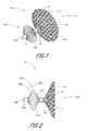
- FIG. 1is a perspective view of an occlusion device in accordance with the present invention.
- FIG. 2is a side elevational view of the occlusion device shown in FIG. 1 .
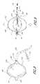
- FIG. 3is a perspective view of an alternate embodiment of the present invention.
- FIG. 4is a side elevational view of the embodiment shown in FIG. 3 .
- FIG. 5is a perspective view of a further embodiment of the present invention.
- FIG. 6is a side elevational view of the embodiment of FIG. 5 .
- FIG. 7is a perspective view of a support structure for a further occlusion device in accordance with the present invention.
- FIG. 7Ais a side elevational view of the device of FIG. 7 .
- FIG. 7Bis an end view taken along the line 7 B- 7 B of FIG. 7A .
- FIG. 8is a schematic illustration of an inflatable balloon positioned within the occlusion device of FIG. 7 .
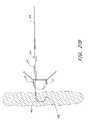
- FIG. 9is a schematic view of a pull string deployment embodiment of the occlusion device of FIG. 7 .
- FIGS. 10 and 11are side elevational schematic representations of partial and complete barrier layers on the occlusion device of FIG. 7 .
- FIG. 12is a side elevational schematic view of an alternate occlusion device in accordance with the present invention.
- FIG. 13is a schematic view of a bonding layer mesh for use in forming a composite barrier membrane in accordance with the present invention.
- FIG. 14is an exploded cross sectional view of the components of a composite barrier member in accordance with the present invention.
- FIG. 15is a cross sectional view through a composite barrier formed from the components illustrated in FIG. 14 .
- FIG. 16is a top plan view of the composite barrier illustrated in FIG. 15 .
- FIG. 17is a schematic view of a deployment system in accordance with the present invention.
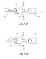
- FIG. 17Ais an enlarged view of a releasable lock in an engaged configuration.
- FIG. 17Bis an enlarged view as in FIG. 17A , with the core axially retracted to release the implant.
- FIG. 18is a perspective view of a flexible guide tube for use in the configurations of FIG. 17 and/or FIG. 19 .
- FIG. 19is a schematic view of an alternate deployment system in accordance with the present invention.
- FIGS. 19A-19Billustrate a removal sequence for an implanted device in accordance with the present invention.
- FIG. 20is a schematic cross sectional view through the distal end of a retrieval catheter having an occlusion device removably connected thereto.
- FIG. 20Ais a side elevational schematic view of the system illustrated in FIG. 20 , with the occlusion device axially elongated and radially reduced.
- FIG. 20Bis a side elevational schematic view as in FIG. 20A , with the occlusion device drawn part way into the delivery catheter.
- FIG. 20Cis a schematic view as in FIG. 20B , with the occlusion device and delivery catheter drawn into a transeptal sheath.
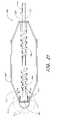
- FIG. 21is a side view of an active expander in accordance with the present invention in the radially compressed state.
- FIG. 21Ais an exploded view of the distal end of the active expander in FIG. 21 .
- FIGS. 21B and 21Care cross-sectional views of the torque rod and fitting in FIGS. 21 and 21A .
- FIG. 22Ais a side view of the active expander in FIG. 21 in a partially radially expanded state.
- FIG. 22Bis a side view of the active expander in FIG. 21 in a radially expanded state.
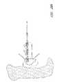
- FIG. 23is a side view of another embodiment of an active expander in accordance with the present invention in the radially compressed state.
- FIG. 24Ais a side view of the active expander in FIG. 23 in a partially radially expanded state.
- FIG. 24Bis a side view of the active expander in FIG. 23 in a radially expanded state.
- FIGS. 24C and 24Dare cross-sectional views of the torque rod and fitting in FIGS. 23 , 24 A and 24 B.
- FIG. 25is a side view of an active anchor in accordance with the present invention in an undeployed state.
- FIGS. 25A and 25Bare cross-sectional views of the torque rod and cavity in FIG. 25 .
- FIG. 26is a side view of the active anchor of FIG. 25 in a deployed state.
- FIG. 27Ais a side fragmentary view of another embodiment of an active anchor in accordance with the present invention, in an undeployed state.
- FIG. 27Bis a side view of the active anchor in FIG. 27A , in a partially deployed state.
- FIG. 27Cis a side view of the active anchor in FIG. 27A in a deployed state.
- FIG. 28Ais a side fragmentary view of another embodiment of an active anchor in accordance with the present invention in an undeployed state.
- FIG. 28Bis a side view of the active anchor in FIG. 28A , in a partially deployed state.
- FIG. 28Cis a side view of the active anchor in FIG. 28A , in a deployed state.
- FIGS. 1 and 2there is illustrated one embodiment of the occlusion device 10 in accordance with the present invention.
- the present inventionwill be described primarily in the context of an occlusion device, the present inventors also contemplate omitting the fabric cover or enlarging the pore size to produce implantable filters or other devices which are enlargeable at a remote implantation site.
- the occlusion device 10comprises an occluding member 11 comprising a frame 14 and a barrier 15 .
- the frame 14comprises a plurality of radially outwardly extending spokes 17 each having a length within the range of from about 0.5 cm to about 2 cm from a hub 16 .
- the spokeshave an axial length of about 1.5 cm.
- anywhere within the range of from about 3 cm to about 40 cmmay be utilized. In some embodiments, anywhere from about 12 to about 24 cm are utilized, and, 18 spokes are utilized in one embodiment.
- the spokesare advanceable from a generally axially extending orientation such as to fit within a tubular introduction catheter to a radially inclined orientation as illustrated in FIG. 1 and FIG. 2 following deployment from the catheter.
- the spokesare biased radially outwardly such that the occlusion member expands to its enlarged, implantation cross-section under its own bias following deployment from the catheter.
- the occlusion membermay be enlarged using any of a variety of enlargement structures such as an inflatable balloon, or a catheter for axially shortening the occlusion member, as is discussed further below.
- the spokescomprise a metal such as stainless steel, Nitinol, Elgiloy, or others which can be determined through routine experimentation by those of skill in the art.
- Wires having a circular or rectangular cross-sectionmay be utilized depending upon the manufacturing technique.
- rectangular cross section spokesare cut such as by known laser cutting techniques from tube stock, a portion of which forms the hub 16 .
- the barrier 15may comprise any of a variety of materials which facilitate cellular in-growth, such as ePTFE. The suitability of alternate materials for barrier 15 can be determined through routine experimentation by those of skill in the art.
- the barrier 15may be provided on either one or both axially facing sides of the occlusion member.
- the barrier 15comprises two layers, with one layer on each side of the frame 14 .
- the two layersmay be bonded to each other around the spokes 17 in any of a variety of ways, such as by heat bonding with or without an intermediate bonding layer such as polyethylene or FEP, adhesives, sutures, and other techniques which will be apparent to those of skill in the art in view of the disclosure herein.
- the barrier 15preferably has a thickness of no more than about 0.003′′ and a porosity within the range of from about 5 ⁇ m to about 60 ⁇ m.
- the barrier 15in one embodiment preferably is securely attached to the frame 14 and retains a sufficient porosity to facilitate cellular ingrowth and/or attachment.
- a bonding layer 254preferably comprises a mesh or other porous structure having an open surface area within the range of from about 10% to about 90%.
- the open surface area of the meshis within the range of from about 30% to about 60%.
- the opening or pore size of the bonding layer 254is preferably within the range of from about 0.005 inches to about 0.050 inches, and, in one embodiment, is about 0.020 inches.
- the thickness of the bonding layer 254can be varied widely, and is generally within the range of from about 0.0005 inches to about 0.005 inches. In a preferred embodiment, the bonding layer 254 has a thickness of about 0.001 to about 0.002 inches.
- One suitable polyethylene bonding meshis available from Smith and Nephew, under the code SN9.
- the bonding layer 254is preferably placed adjacent one or both sides of a spoke or other frame element 14 .
- the bonding layer 254 and frame 14 layersare then positioned in-between a first membrane 250 and a second membrane 252 to provide a composite membrane stack.
- the first membrane 250 and second membrane 252may comprise any of a variety of materials and thicknesses, depending upon the desired functional result.
- the membranehas a thickness within the range of from about 0.0005 inches to about 0.010 inches.
- the membranes 250 and 252each have a thickness on the order of from about 0.001 inches to about 0.002 inches, and comprise porous ePTFE, having a porosity within the range of from about 10 microns to about 100 microns.
- the composite stackis heated to a temperature of from about 200° F. to about 300° F., for about 1 minute to about 5 minutes under pressure to provide a finished composite membrane assembly with an embedded frame 14 as illustrated schematically in FIG. 15 .
- the final composite membranehas a thickness within the range of from about 0.001 inches to about 0.010 inches, and, preferably, is about 0.002 to about 0.003 inches in thickness.
- the thicknesses and process parameters of the foregoingmay be varied considerably, depending upon the materials of the bonding layer 254 the first layer 250 and the second layer 252 .
- the resulting finished composite membranehas a plurality of “unbonded” windows or areas 256 suitable for cellular attachment and/or ingrowth.
- the attachment areas 256are bounded by the frame 14 struts, and the cross-hatch or other wall pattern formed by the bonding layer 254 .
- a regular window 256 patternis produced in the bonding layer 254 .
- the foregoing procedureallows the bonding mesh to flow into the first and second membranes 250 and 252 and gives the composite membrane 15 greater strength (both tensile and tear strength) than the components without the bonding mesh.
- the compositeallows uniform bonding while maintaining porosity of the membrane 15 , to facilitate tissue attachment.
- By flowing the thermoplastic bonding layer into the pores of the outer mesh layers 250 and 252the composite flexibility is preserved and the overall composite layer thickness can be minimized.
- the occlusion device 10may be further provided with a bulking element or stabilizer 194 .
- the stabilizer 194may be spaced apart along an axis from the occluding member 11 .
- a distal end 190 and a proximal end 192are identified for reference.
- the designation proximal or distalis not intended to indicate any particular anatomical orientation or deployment orientation within the deployment catheter.
- the stabilizer 194is spaced distally apart from the occluding member 11 .
- the occluding member 11has an expanded diameter within the range of from about 1 cm to about 5 cm, and, in one embodiment, about 3 cm.
- the axial length of the occluding member 11 in an expanded, unstressed orientation from the distal end 192 to the hub 16is on the order of about 1 cm.
- the overall length of the occlusion device 10 from the distal end 192 to the proximal end 190is within the range of from about 1.5 cm to about 4 cm and, in one embodiment, about 2.5 cm.
- the axial length of the stabilizer 194 between distal hub 191 and proximal hub 16is within the range of from about 0.5 cm to about 2 cm, and, in one embodiment, about 1 cm.
- the expanded diameter of the stabilizer 194is within the range of from about 0.5 cm to about 2.5 cm, and, in one embodiment, about 1.4 cm.
- the outside diameter of the distal hub 191 and proximal hub 16is about 2.5 mm.
- the occlusion device 10is provided with one or more retention structures for retaining the device in the left atrial appendage or other body cavity or lumen.
- a plurality of barbs or other anchors 195are provided, for engaging adjacent tissue to retain the occlusion device 10 in its implanted position and to limit relative movement between the tissue and the occlusion device.
- the illustrated anchorsare provided on one or more of the spokes 17 , or other portion of frame 14 .
- every spoke, every second spoke or every third spokeare provided with one or two or more anchors each.
- the illustrated anchoris in the form of a barb, with one on each spoke for extending into tissue at or near the opening of the LAA.
- two or three barbsmay alternatively be desired on each spoke.
- each barbis inclined in a proximal direction. This is to inhibit proximal migration of the implant out of the left atrial appendage.
- distalrefers to the direction into the left atrial appendage
- proximalrefers to the direction from the left atrial appendage into the heart.
- one or more barbsmay face distally, to inhibit distal migration of the occlusion device deeper into the LAA.
- the implantmay be provided with at least one proximally facing barb and at least one distally facing barb.
- a proximal plurality of barbsmay be inclined in a first direction
- a distal plurality of barbsmay be inclined in a second direction, to anchor the implant against both proximal and distal migration.
- anchors 195may also be provided on the stabilizer 194 , such that it assists not only in orienting the occlusion device 10 and resisting compression of the LAA, but also in retaining the occlusion device 10 within the LAA.
- Any of a wide variety of structuresmay be utilized for anchor 195 , either on the occluding member 11 or the stabilizer 194 or both, such as hooks, barbs, pins, sutures, adhesives, ingrowth surfaces and others which will be apparent to those of skill in the art in view of the disclosure herein.
- the occlusion device 10is preferably positioned within a tubular anatomical structure to be occluded such as the left atrial appendage.
- the occluding member 11is positioned across or near the opening to the LAA and the stabilizer 194 is positioned within the LAA.
- the stabilizer 194assists in the proper location and orientation of the occluding member 11 , as well as resists compression of the LAA behind the occluding member 11 .
- the present inventorshave determined that following deployment of an occluding member 11 without a stabilizer 194 or other bulking structure to resist compression of the LAA, normal operation of the heart may cause compression and resulting volume changes in the LAA, thereby forcing fluid past the occluding member 11 and inhibiting or preventing a complete seal. Provision of a stabilizer 194 dimensioned to prevent the collapse or pumping of the LAA thus minimizes leakage, and provision of the barbs facilitates endothelialization or other cell growth across the occluding member 11 .
- the stabilizer 194is preferably movable between a reduced cross-sectional profile for transluminal advancement into the left atrial appendage, and an enlarged cross-sectional orientation as illustrated to fill or to substantially fill a cross-section through the LAA.
- the stabilizing membermay enlarge to a greater cross section than the (pre-stretched) anatomical cavity, to ensure a tight fit and minimize the likelihood of compression.
- One convenient constructionincludes a plurality of elements 196 which are radially outwardly expandable in response to axial compression of a distal hub 191 towards a proximal hub 16 .
- Elements 196each comprise a distal segment 198 and a proximal segment 202 connected by a bend 200 .
- the elements 196may be provided with a bias in the direction of the radially enlarged orientation as illustrated in FIG. 2 , or may be radially expanded by applying an expansion force such as an axially compressive force between distal hub 191 and proximal hub 16 or a radial expansion force such as might be applied by an inflatable balloon.
- Elements 196may conveniently be formed by laser cutting the same tube stock as utilized to construct the distal hub 191 , proximal hub 16 and frame 14 , as will be apparent to those of skill in the art in view of the disclosure herein.
- the various components of the occlusion device 10may be separately fabricated or fabricated in subassemblies and secured together during manufacturing.
- a radiopaque dye or other visualizable mediamay be introduced on one side or the other of the occlusion device, to permit visualization of any escaped blood or other fluid past the occlusion device.
- the occlusion devicemay be provided with a central lumen or other capillary tube or aperture which permits introduction of a visualizable dye from the deployment catheter through the occlusion device and into the entrapped space on the distal side of the occlusion device.
- dyemay be introduced into the entrapped space distal to the occlusion device such as by advancing a small gauge needle from the deployment catheter through the barrier 15 on the occlusion device, to introduce dye.
- the occlusion device 10comprises an occlusion member 11 and a stabilizing member 194 as previously discussed.
- each of the distal segments 198inclines radially outwardly in the proximal direction and terminates in a proximal end 204 .
- the proximal end 204may be provided with an atraumatic configuration, for pressing against, but not penetrating, the wall of the left atrial appendage or other tubular body structure.
- Three or more distal segments 198are preferably provided, and generally anywhere within the range of from about 6 to about 20 distal segments 198 may be used. In one embodiment, 9 distal segments 198 are provided.
- three of the distal segments 198have an axial length of about 5 mm, and 6 of the distal segments 198 have an axial length of about 1 cm. Staggering the lengths of the distal segments 198 may axially elongate the zone in the left atrial appendage against which the proximal ends 204 provide anchoring support for the occlusion device.
- the occlusion device 10 illustrated in FIGS. 3 and 4is additionally provided with a hinge 206 to allow the longitudinal axis of the occlusion member 11 to be angularly oriented with respect to the longitudinal axis of the stabilizing member 194 .
- the hinge 206is a helical coil, although any of a variety of hinge structures can be utilized.
- the illustrated embodimentmay be conveniently formed by laser cutting a helical slot through a section of the tube from which the principal structural components of the occlusion device 10 are formed.
- an annular band 208connects the hinge 206 to a plurality of axially extending struts 210 .
- Axial struts 210are provided, spaced equilaterally around the circumference of the body.
- Axial struts 210may be formed from a portion of the wall of the original tube stock, which portion is left in its original axial orientation following formation of the distal segments 198 such as by laser cutting from the tubular wall.
- the occlusion member 11is provided with a proximal zone 212 on each of the spokes 17 .
- Proximal zone 212has an enhanced degree of flexibility, to accommodate the fit between the occlusion member 11 and the wall of the left atrial appendage.
- Proximal section 212may be formed by reducing the cross sectional area of each of the spokes 17 , which may be provided with a wave pattern as illustrated.
- Proximal point 214may be contained within layers of the barrier 15 , or may extend through or beyond the barrier 15 such as to engage adjacent tissue and assist in retaining the occlusion device 10 at the deployment site.
- the occlusion device 10is provided with a proximal face 216 on the occlusion member 11 , instead of the open and proximally concave face on the embodiment of FIGS. 1 and 2 .
- the proximal face 216is formed by providing a proximal spoke 218 which connects at an apex 220 to some or all of the distal spokes 17 .
- the proximal spoke 218 , and corresponding apex 220 and distal spoke 17may be an integral structure, such as a single ribbon or wire, or element cut from a tube stock as has been discussed.
- Proximal spokes 218are each attached to a hub 222 at the proximal end 192 of the occlusion device 10 .
- the barrier 15may surround either the proximal face or the distal face or both on the occlusion member 11 .
- provision of a proximal spoke 218 connected by an apex 220 to a distal spoke 17provides a greater radial force than a distal spoke 17 alone, which will provide an increased resistance to compression if the occlusion member 11 is positioned with the LAA.
- the occlusion device 10comprises an occluding member but does not include a distinct stabilizing member as has been illustrated in connection with previous embodiments. Any of the embodiments previously disclosed herein may also be constructed using the occluding member only, and omitting the stabilizing member as will be apparent to those of skill in the art in view of the disclosure herein.
- the occluding device 10comprises a proximal end 192 , a distal end 190 , and a longitudinal axis extending therebetween.
- a plurality of supports 228extend between a proximal hub 222 and a distal hub 191 . At least two or three supports 228 are provided, and preferably at least about ten. In one embodiment, sixteen supports 228 are provided. However, the precise number of supports 228 can be modified, depending upon the desired physical properties of the occlusion device 10 as will be apparent to those of skill in the art in view of the disclosure herein, without departing from the present invention.
- Each support 228comprises a proximal spoke portion 218 , a distal spoke portion 17 , and an apex 220 as has been discussed.
- Each of the proximal spoke portion 218 , distal spoke portion 17 and apex 220may be a region on an integral support 228 , such as a continuous rib or frame member which extends in a generally curved configuration as illustrated with a concavity facing towards the longitudinal axis of the occlusion device 10 .
- no distinct point or hinge at apex 220is necessarily provided.
- each support 228is provided with one or two or more barbs 195 .
- the occlusion device 10is in its enlarged orientation, such as for occluding a left atrial appendage or other body cavity or lumen.
- each of the barbs 195projects generally radially outwardly from the longitudinal axis, and is inclined in the proximal direction.
- One or more barbsmay also be inclined distally, as is discussed elsewhere herein.
- the barbs 195 and corresponding support 228are cut from a single ribbon, sheet or tube stock, the barb 195 will incline radially outwardly at approximately a tangent to the curve formed by the support 228 .
- the occlusion device 10 constructed from the frame illustrated in FIG. 7may be constructed in any of a variety of ways, as will become apparent to those of skill in the art in view of the disclosure herein.
- the occlusion device 10is constructed by laser cutting a piece of tube stock to provide a plurality of axially extending slots in-between adjacent supports 228 .
- each barb 195can be laser cut from the corresponding support 228 or space in-between adjacent supports 228 .
- the generally axially extending slots which separate adjacent supports 228end a sufficient distance from each of the proximal end 192 and distal end 190 to leave a proximal hub 222 and a distal hub 191 to which each of the supports 228 will attach.
- an integral cage structuremay be formed.
- each of the components of the cage structuremay be separately formed and attached together such as through soldering, brazing, heat bonding, adhesives, and other fastening techniques which are known in the art.
- a further method of manufacturing the occlusion device 10is to laser cut a slot pattern on a flat sheet of appropriate material, such as a flexible metal or polymer, as has been discussed in connection with previous embodiments. The flat sheet may thereafter be rolled about an axis and opposing edges bonded together to form a tubular structure.
- the apex portion 220 which carries the barb 195may be advanced from a low profile orientation in which each of the supports 228 extend generally parallel to the longitudinal axis, to an implanted orientation as illustrated, in which the apex 220 and the barb 195 are positioned radially outwardly from the longitudinal axis.
- the support 228may be biased towards the enlarged orientation, or may be advanced to the enlarged orientation under positive force following positioning within the tubular anatomical structure, in any of a variety of manners.
- an inflatable balloon 230is positioned within the occlusion device 10 .
- Inflatable balloon 230is connected by way of a removable coupling 232 to an inflation catheter 234 .
- Inflation catheter 234is provided with an inflation lumen for providing communication between an inflation media source 236 outside of the patient and the balloon 230 .
- the balloon 230is inflated, thereby engaging barbs 195 with the surrounding tissue.
- the inflation catheter 234is thereafter removed, by decoupling the removable coupling 232 , and the inflation catheter 234 is thereafter removed.
- the balloon 230may be either left in place within the occlusion device 10 , or deflated and removed by the inflation catheter 234 .
- the supports 228are radially enlarged such as through the use of a deployment catheter 238 .
- Deployment catheter 238comprises a lumen for movably receiving a deployment element such as a flexible line 240 .
- Deployment line 240extends in a loop 244 formed by an aperture or slip knot 242 .
- proximal retraction on the deployment line 240 while resisting proximal movement of proximal hub 222such as by using the distal end of the catheter 238 will cause the distal hub 191 to be drawn towards the proximal hub 222 , thereby radially enlarging the cross-sectional area of the occlusion device 10 .
- the supports 228will retain the radially enlarged orientation by elastic deformation, or may be retained in the enlarged orientation such as by securing the slip knot 242 immovably to the deployment line 240 at the fully radially enlarged orientation. This may be accomplished in any of a variety of ways, using additional knots, clips, adhesives, or other techniques known in the art.
- a pullwire 240may be removably attached to the distal hub 191 or other distal point of attachment on the occlusion device 10 . Proximal retraction of the pullwire 240 while resisting proximal motion of the proximal hub 222 such as by using the distal end of the catheter 238 will cause enlargement of the occlusion device 10 as has been discussed.
- the pullwire 240may then be locked with respect to the proximal hub 222 and severed or otherwise detached to enable removal of the deployment catheter 238 and proximal extension of the pullwire 240 . Locking of the pullwire with respect to the proximal hub 222 may be accomplished in any of a variety of ways, such as by using interference fit or friction fit structures, adhesives, a knot or other technique depending upon the desired catheter design.
- the occlusion device 10may be provided with a barrier 15 such as a mesh or fabric as has been previously discussed.
- Barrier 15may be provided on only one hemisphere such as proximal face 216 , or may be carried by the entire occlusion device 10 from proximal end 192 to distal end 190 .
- the barriermay be secured to the radially inwardly facing surface of the supports 228 , as illustrated in FIG. 11 , or may be provided on the radially outwardly facing surfaces of supports 228 , or both.
- FIG. 12A further embodiment of the occlusion device 10 is illustrated in FIG. 12 , in which the apex 220 is elongated in an axial direction to provide additional contact area between the occlusion device 10 and the wall of the tubular structure.
- one or two or three or more anchors 195may be provided on each support 228 , depending upon the desired clinical performance.
- the occlusion device 10 illustrated in FIG. 12may also be provided with any of a variety of other features discussed herein, such as a partial or complete barrier 15 .
- the occlusion device 10 illustrated in FIG. 12may be enlarged using any of the techniques disclosed elsewhere herein.
- An adjustable implant deployment system 300comprises generally a catheter 302 for placing a detachable implant 304 within a body cavity or lumen, as has been discussed.
- the catheter 302comprises an elongate flexible tubular body 306 , extending between a proximal end 308 and a distal end 310 .
- the catheteris shown in highly schematic form, for the purpose of illustrating the functional aspects thereof.
- the catheter bodywill have a sufficient length and diameter to permit percutaneous entry into the vascular system, and transluminal advancement through the vascular system to the desired deployment site.
- the catheter 302will have a length within the range of from about 50 cm to about 150 cm, and a diameter of generally no more than about 15 French. Further dimensions and physical characteristics of catheters for navigation to particular sites within the body are well understood in the art and will not be further described herein.
- the tubular body 306is further provided with a handle 309 generally on the proximal end 308 of the catheter 302 .
- the handle 309permits manipulation of the various aspects of the implant deployment system 300 , as will be discussed below.
- Handle 309may be manufactured in any of a variety of ways, typically by injection molding or otherwise forming a handpiece for single-hand operation, using materials and construction techniques well known in the medical device arts.
- the implant 304may be in the form of any of those described previously herein, as modified below.
- the implantis movable from a reduced crossing profile to an enlarged crossing profile, such that it may be positioned within a body structure and advanced from its reduced to its enlarged crossing profile to obstruct bloodflow or perform other functions while anchored therein.
- the implant 304may be biased in the direction of the enlarged crossing profile, may be neutrally biased or may be biased in the direction of the reduced crossing profile. Any modifications to the device and deployment system to accommodate these various aspects of the implant 304 may be readily accomplished by those of skill in the art in view of the disclosure herein.
- the distal end 314 of the implant 304is provided with an implant plug 316 .
- Implant plug 316provides a stopping surface 317 for contacting an axially movable core 312 .
- the core 312extends axially throughout the length of the catheter body 302 , and is attached at its proximal end to a core control 332 on the handle 309 .
- the core 312may comprise any of a variety of structures which has sufficient lateral flexibility to permit navigation of the vascular system, and sufficient axial column strength to enable reduction of the implant 304 to its reduced crossing profile. Any of a variety of structures such as hypotube, solid core wire, “bottomed out” coil spring structures, or combinations thereof may be used, depending upon the desired performance of the finished device.
- the core 312comprises stainless steel tubing.
- the distal end of core 312is positioned within a recess or lumen 322 defined by a proximally extending guide tube 320 .
- the guide tube 320is a section of tubing such as metal hypotube, which is attached at the distal end 314 of the implant and extends proximally within the implant 304 .
- the guide tube 320preferably extends a sufficient distance in the proximal direction to inhibit buckling or prolapse of the core 312 when distal pressure is applied to the core control 332 to reduce the profile of the implant 304 .
- the guide tube 320should not extend proximally a sufficient distance to interfere with the opening of the implant 304 .
- the guide tube 320may operate as a limit on distal axial advancement of the proximal end 324 of implant 304 .
- the guide tube 320preferably does not extend sufficiently far proximally from the distal end 314 to interfere with optimal opening of the implant 304 .
- the specific dimensionsare therefore relative, and will be optimized to suit a particular intended application.
- the implant 304has an implanted outside diameter within the range of from about 5 mm to about 45 mm, and an axial implanted length within the range of from about 5 mm to about 45 mm.
- the guide tube 320has an overall length of about 3 mm to about 35 mm, and an outside diameter of about 0.095 inches.
- FIG. 18An alternate guide tube 320 is schematically illustrated in FIG. 18 .
- the guide tube 320comprises a plurality of tubular segments 321 spaced apart by an intervening space 323 .
- Thisallows increased flexibility of the guide tube 320 , which may be desirable during the implantation step, while retaining the ability of the guide tube 320 to maintain linearity of the core 312 while under axial pressure.
- three segments 321are illustrated in FIG. 18 , as many as 10 or 20 or more segments 321 may be desirable depending upon the desired flexibility of the resulting implant.
- each adjacent pair of segments 321may be joined by a hinge element 325 which permits lateral flexibility.
- the hinge element 325comprises an axially extending strip or spine, which provides column strength along a first side of the guide tube 320 .
- the guide tube 320may therefore be curved by compressing a second side of the guide tube 320 which is generally offset from the spine 325 by about 180°.
- a limit on the amount of curvaturemay be set by adjusting the axial length of the space 323 between adjacent segments 321 .
- each axial spine 325may be rotationally offset from the next adjacent axial spine 325 to enable flexibility of the overall guide tube 320 throughout a 360° angular range of motion.
- each adjacent segment 321may be provided by cutting a spiral groove or plurality of parallel grooves in a tubular element in between what will then become each adjacent pair of segments 321 .
- each tubular element 321will be separated by an integral spring like structure, which can permit flexibility.
- the entire length of the guide tube 320may comprise a spring.
- Each of the forgoing embodimentsmay be readily constructed by laser cutting or other cutting from a piece of tube stock, to produce a one piece guide tube 320 .
- the guide tube 320may be assembled from separate components and fabricated together using any of a variety of bonding techniques which are appropriate for the construction material selected for the tube 320 .
- the distal implant plug 316extends within the implant 304 and is attached to the distal end of the guide tube 320 .
- the implant plug 316may be secured to the guide tube 320 and implant 304 in any of a variety of ways, depending upon the various construction materials. For example, any of a variety of metal bonding techniques such as a welding, brazing, interference fit such as threaded fit or snap fit, may be utilized. Alternatively, any of a variety of bonding techniques for dissimilar materials may be utilized, such as adhesives, and various molding techniques.
- the implant plug 316comprises a molded polyethylene cap, and is held in place utilizing a distal cross pin 318 which extends through the implant 304 , the guide tube 320 and the implant plug 316 to provide a secure fit against axial displacement.
- the proximal end 324 of the implant 304is provided with a releasable lock 326 for attachment to a release element such as pull wire 328 .
- Pull wire 328extends proximally throughout the length of the tubular body 306 to a proximal pull wire control 330 on the handle 309 .
- the term pull wireis intended to include any of a wide variety of structures which are capable of transmitting axial tension or compression such as a pushing or pulling force with or without rotation from the proximal end 308 to the distal end 310 of the catheter 302 .
- monofilament or multifilament metal or polymeric rods or wires, woven or braided structuresmay be utilized.
- tubular elementssuch as a concentric tube positioned within the outer tubular body 306 may also be used as will be apparent to those of skill in the art.
- the pull wire 328is releasably connected to the proximal end 324 of the implant 304 .
- Thispermits proximal advancement of the proximal end of the implant 304 , which cooperates with a distal retention force provided by the core 312 against the distal end of the implant to axially elongate the implant 304 thereby reducing it from its implanted configuration to its reduced profile for implantation.
- the proximal end of the pull wire 328may be connected to any of a variety of pull wire controls 330 , including rotational knobs, levers and slider switches, depending upon the design preference.
- the proximal end 324 of the implant 304is thus preferably provided with a releasable lock 326 for attachment of the pullwire 328 to the deployment catheter.
- the releasable lockis formed by advancing the pullwire distally around a cross pin 329 , and providing an eye or loop which extends around the core 312 . As long as the core 312 is in position within the implant 304 , proximal retraction of the pullwire 328 will advance the proximal end 324 of the implant 304 in a proximal direction. See FIG. 17A .
- proximal retraction of the core 312such as by manipulation of the core control 332 will pull the distal end of the core 312 through the loop on the distal end of the pullwire 328 .
- the pullwire 328may then be freely proximally removed from the implant 304 , thereby enabling detachment of the implant 304 from the deployment system 300 within a treatment site. See FIG. 17B .
- the implant deployment system 300thus permits the implant 304 to be maintained in a low crossing profile configuration, to enable transluminal navigation to a deployment site. Following positioning at or about the desired deployment site, proximal retraction of the core 312 enables the implant 304 to radially enlarge under its own bias to fit the surrounding tissue structure. Alternatively, the implant can be enlarged under positive force, such as by inflation of a balloon or by a mechanical mechanism as is discussed elsewhere herein. Once the clinician is satisfied with the position of the implant 304 , such as by injection of dye and visualization using conventional techniques, the core 312 is proximally retracted thereby releasing the lock 326 and enabling detachment of the implant 304 from the deployment system 300 .
- the present inventionpermits the implant 304 to be enlarged or reduced by the clinician to permit repositioning and/or removal of the implant 304 as may be desired.
- the implantmay be radially enlarged or reduced by rotating a torque element extending throughout the deployment catheter.
- the elongate flexible tubular body 306 of the deployment catheter 302includes a rotatable torque rod 340 extending axially therethrough.
- the proximal end of the torque rod 340may be connected at a proximal manifold to a manual rotation device such as a hand crank, thumb wheel, rotatable knob or the like.
- the torque rod 340may be connected to a power driven source of rotational energy such as a motor drive or air turbine.
- the distal end of the torque rod 340is integral with or is connected to a rotatable core 342 which extends axially through the implant 304 .
- a distal end 344 of the rotatable core 342is positioned within a cavity 322 as has been discussed.
- torque rod or torque elementare intended to include any of a wide variety of structures which are capable of transmitting a rotational torque throughout the length of a catheter body.
- solid core elementssuch as stainless steel, nitinol or other nickel titanium alloys, or polymeric materials may be utilized.
- the torque rod 340is preferably provided with an axially extending central guidewire lumen. This may be accomplished by constructing the torque rod 340 from a section of hypodermic needle tubing, having an inside diameter of from about 0.001 inches to about 0.005 inches or more greater than the outside diameter of the intended guidewire.
- Tubular torque rods 340may also be fabricated or constructed utilizing any of a wide variety of polymeric constructions which include woven or braided reinforcing layers in the wall. Torque transmitting tubes and their methods of construction are well understood in the intracranial access and rotational atherectomy catheter arts, among others, and are not described in greater detail herein. Use of a tubular torque rod 340 also provides a convenient infusion lumen for injection of contrast media within the implant 304 , such as through a port 343 .
- the proximal end 324 of the implant 304is provided with a threaded aperture 346 through which the core 342 is threadably engaged.
- rotation of the threaded core 342 in a first direction relative to the proximal end 324 of the implant 304will cause the rotatable core 342 to advance distally. This distal advancement will result in an axial elongation and radial reduction of the implantable device 304 .
- Rotation of the rotatable core 342 in a reverse directionwill cause a proximal retraction of the rotatable core 342 , thus enabling a radial enlargement and axial shortening of the implantable device 304 .
- the deployment catheter 302is further provided with an antirotation lock 348 between a distal end 350 of the tubular body 306 and the proximal end 324 of the implant 304 .
- the rotational lock 348may be conveniently provided by cooperation between a first surface 352 on the distal end 350 of the deployment catheter 302 , which engages a second surface 354 on the proximal end 324 of the implantable device 304 , to rotationally link the deployment catheter 302 and the implantable device 304 .
- Any of a variety of complementary surface structuresmay be provided, such as an axial extension on one of the first and second surfaces for coupling with a corresponding recess on the other of the first and second surfaces.
- Such extensions and recessesmay be positioned laterally offset from the axis of the catheter. Alternatively, they may be provided on the longitudinal axis with any of a variety of axially releasable anti-rotational couplings having at least one flat such as a hexagonal or other multifaceted cross sectional configuration.
- one or more projections 356 on the first surface 352may engage a corresponding recess 358 on the second surface 354 .
- Any of a variety of alternative complementary surface structuresmay also be provided, as will be apparent to those of skill in the art in view of the disclosure herein.
- the projection 356is in the form of an axially extending pin for engaging a complimentary recess 358 on the proximal end 324 of the implant 304 .
- FIG. 19Billustrates an axially extending spline 356 for receipt within a complimentary axially extending recess 358 .
- the various pin, spline and other structuresmay be reversed between the distal end of tubular body 306 and the proximal end 324 of the implant 304 as will be apparent to those of skill in the art in view of the disclosure herein.
- the torque rod 340Upon placement of the implantable device 304 at the desired implantation site, the torque rod 340 is rotated in a direction that produces an axial proximal retraction. This allows radial enlargement of the radially outwardly biased implantable device 304 at the implantation site. Continued rotation of the torque rod 340 will cause the threaded core 342 to exit proximally through the threaded aperture 346 . At that point, the deployment catheter 302 may be proximally retracted from the patient, leaving the implanted device 304 in place.
- the rotatable core 342may be left within the implantable device 304 , as may be desired depending upon the intended deployment mechanism.
- the distal end of the core 342may be rotatably locked within the end cap 326 , such as by including complimentary radially outwardly or inwardly extending flanges and grooves on the distal end of the core 342 and inside surface of the cavity 322 .
- proximal retraction of the core 342 by rotation thereof relative to the implantable device 304will pull the end cap 326 in a proximal direction under positive force. This may be desirable as a supplement to or instead of a radially enlarging bias built into the implantable device 304 .
- a positive expansion forcemay also be achieved in the embodiment illustrated in FIG. 21 .
- a first coil 402is fixedly attached to the proximal end 324 of the implant.
- a second coil 404is rotatably locked within the end cap 326 , such as by complimentary radially inwardly extending tabs or flanges 407 on the inside surface of the cavity 322 , and radially inwardly extending groove or radially outwardly extending surface 408 on the outside surface of the distal end of the second coil.
- the second coil 404can be rotatably locked within the end cap 326 by complimentary radially outwardly extending flanges on the outside surface of the distal end of the second coil, and grooves on the inside surface of the cavity.
- a torque rod 340passes through an aperture 400 in the proximal end 324 of the implant 304 , through the first coil 402 , through the second coil 404 , and into a fitting 412 in the distal end of the second coil.
- the distal end 414 of the torque rod 340has an exterior cross-sectional profile that corresponds to the interior cross-sectional profile of the fitting 412 .
- the torque rodis able to slide freely longitudinally within the fitting 412 and is able to apply a rotational torque to the fitting.
- the interior lumen of the fitting 412may have an oval cross section.
- the exterior of the distal section of the distal end of the torque rod 414preferably has a complimentary cross section.
- the complimentary cross sectionscould also be any other shape, such as a triangle, square, hexagon, ellipse, circle with one or more complimentary intruding and extruding pins, splines, flanges, grooves or other structures disclosed elsewhere herein, or any other regular or irregular polygon that would allow the torque rod 340 to apply a rotational torque to the fitting 412 .
- applying a rotational force to the torque rodcauses the second coil 404 to engage the first coil 402 .
- This engagementallows rotation of the torque rod in a first direction to cause axial compression and radial expansion of the implant 304 . This allows for precise fitting of the implant within the cavity.
- the first coil 402 and the second coil 404 , together with the adjacent tubular supportmay be manufactured in any of a variety of ways which will be understood by those of skill in the art.
- a stainless steel tube stockhaving an inside diameter of about 0.040 inches and an outside diameter of about 0.065 inches is laser-cut according to conventional techniques to form the spiral ribbon.
- the width of the ribbon in the axial directionis about 0.014 inches, and the spacing between adjacent windings of the ribbon, measured in the axial direction, is about 0.020 inches.
- the dimensionsmay be varied widely, depending upon the intended clinical application, construction materials, desired flexibility, and other choices which can be optimized by those of skill in the art in view of the disclosure herein.
- first coil 402 and second coil 404have an approximately equivalent diameter and complimentary structure to allow threadable engagement as illustrated, for example, in FIG. 22A .
- one of the first coil 402 or second coil 404may be replaced by a tubular or other element which is dimensioned to reside adjacent the radially inwardly facing surface of the complimentary coil 402 or 404 or the radially outwardly facing surface of the coil 402 or 404 .
- the resulting componentmay be a tubular element, or axially extending element, having a flange or post which extends radially outwardly or radially inwardly through the space between adjacent windings on the corresponding coil.
- a tubular bodymay replace the first coil 402 and have an outside diameter of slightly less than the inside diameter of the second coil 404 .
- the tubular bodyis provided with one or more radially outwardly extending post or flanges, to engage the spiral groove in the second coil 404 . Operation of the device is similar to that described previously, such that rotation of one component with respect to the other will cause an axial compression or expansion across the operating range.
- the first coil 402is rotatably locked within the proximal end 324 of the implant, and the second coil 404 , is fixedly attached to the end cap 326 .
- the torque rod 340passes through an aperture 400 in the proximal end 324 of the implant 304 , and into a fitting 412 in the proximal end of the first coil 402 .
- the first coil 402is rotatably locked within the proximal end 324 of the implant by any conventional means known to those of ordinary skill in the art, such as by inwardly extending radial flanges 407 and complimentary grooves 408 on the outer surface of the coil.
- the distal end 414 of the torque rod 340has an exterior cross-sectional profile that corresponds to the interior cross-sectional profile of the fitting 412 , as described above in the previous embodiment.
- applying a rotational force to the torque rodcauses the first coil 402 to engage the second coil 404 .
- This engagementcauses axial compression and radial expansion of the implant 304 . This allows for precise fitting of the implant within the cavity as described above.
- first and second coilsmay be any type of threadably engageable first and second members as are conventionally used in the art. The optimum type of threadable engagement can be determined for any particular application and for any particular material or combination of materials through routine experimentation by one or ordinary skill in the art based on the disclosures herein.
- the embodiment of FIG. 19can be modified to provide expansion under positive force by providing a rotatable engagement between the distal end 344 of rotatable core 342 and the surface of cavity 322 .
- Thiswill allow rotation of the core 342 to either radially expand or contract the implant.
- Rotatable screw mechanismsmay, however, reduce the flexibility of the device compared to the embodiment of FIGS. 21-24 , which may inhibit transluminal navigation.
- the distal end of the implantmay be connected to a pull string or pull wire, which extends proximally throughout the length of the catheter. Proximal retraction on the pull wire will axially proximally advance the distal end of the implant, thereby providing positive radial expansion force.
- a pull string or pull wirewhich extends proximally throughout the length of the catheter.
- Proximal retraction on the pull wirewill axially proximally advance the distal end of the implant, thereby providing positive radial expansion force.
- Any of a variety of releasable ratchet or other engagement structuresmay be provided within the implant, for retaining the implant in the expanded configuration.
- the pull wiremay be released, and proximally retracted from the catheter in a manner similar to that discussed in connection with the embodiment of FIG. 17 .
- the pull wiresimply loops around a post or through an eye connected mechanically to the distal end of the implant. Both ends of the pull wire extend all the way to the proximal end of the device. One end of the pull wire may be released from its attachment to the proximal end of the device, and the second end of the pull wire may be proximally retracted, to remove the wire from the device following active expansion at the treatment site.
- the above described axial expansionmay be optionally combined with an implant that is positively, negatively or neutrally biased toward expansion.
- the optimum combination of passive and active expansioncan be determined for any particular application and for any particular material or combination of materials through routine experimentation by one or ordinary skill in the art based on the disclosures herein.
- one or more tissue engagement anchorsmay be provided, as has been discussed, for example, in connection with anchors 195 in the embodiments of FIGS. 9-12 .
- One or more anchorsmay also or alternatively be provided, extending distally along or substantially parallel to the longitudinal axis of the device.
- the longitudinally disposed anchorsdo not extend beyond the distal end 190 of the occlusion device during transluminal navigation to the deployment site.
- one or more distal anchorsare extended beyond the distal end 190 of the occlusion device in order to secure the occlusion device to the surrounding tissue.
- the distal anchor or anchorsmay be extended beyond the distal tip 190 before or during deployment. Extending the distal anchor or anchors before or during deployment may assist in deploying or positioning the device.
- the anchorsmay have sharpened distal tips to facilitate penetration into the surrounding tissue.
- the anchor 420has a distal tissue engaging section 422 .
- the distal section 422is laser-cut from tube stock to form a helix with a circular cross section (corkscrew) with a sharpened distal tip 424 .
- the helical distal section 422is threadably engaged with the distal end 190 of the occlusion device via an engaging member 430 such as a complementary thread or projection.
- a bridge 432may be provided between at least two of the coils of the distal section 422 . The bridge 432 places a rotational limit on the extent to which the anchor can advance toward the proximal end of the occlusion device.
- the bridge 432is between the second and third helical coils from the sharpened distal tip 424 .
- the bridge 432will connect other helical coils depending on the specific application.
- Alternative limiting structuresmay also be used, to limit the proximal and/or distal axial travel of the tissue engaging section 422 with respect to the distal end 190 of the occlusion device.
- the proximal section 426 of the anchor 420has a central lumen or cavity 428 .
- the cavity 428preferably has a non-round cross section.
- a torque rod 340has a distal end 414 .
- the exterior of the distal end of the torque rod 414preferably has a complimentary cross section to the interior cross section of the cavity 428 .
- the complimentary cross sectionscan be other shapes, such as a triangle, square, hexagon, ellipse, circle with one or more complimentary intruding and extruding pins, splines, flanges, grooves or other structures disclosed elsewhere herein, or any other regular or irregular polygon that allows the torque rod 340 to apply a rotational torque to the anchor 420 .
- applying a rotational force to the torque rod 340causes the helical distal section 422 to threadably engage the engaging member 430 .
- the sharpened tip 424facilitates the penetration of the helical distal section 422 into the body tissue 434 .
- the torque rod 340may be retracted proximally and removed from the device.
- the anchor 420 and the torque rod 340both contain a lumen that allows for the introduction of visualizable media on either side of the occlusion device (not illustrated).
- the torque rod 340can be reinserted distally into the anchor and the opposite rotational torque applied to disengage the coils from the tissue.
- the anchor 420is a biocompatible wire or ribbon, preferably made of stainless steel, nitinol or elgiloy.
- the distal section 440 of the anchoris biased to form a curve or hook and the distal tip 442 is sharpened to facilitate tissue penetration.
- the distal section 440 of the anchoris biased to form at least about a 60 degree and as much as about a 300 degree curve or more. In one embodiment the distal section 440 is biased to form a curve of about 180 degrees.
- the anchor 420resides in a substantially linear position within a lumen 444 in an active anchoring device and does not extend beyond the distal tip 191 of the occlusion device.
- the lumen 444is disposed substantially along the longitudinal axis of the occlusion device and may be disposed concentrically, next to, or substantially parallel to any other longitudinally disposed structures, such as the torque rod or collapsing shaft disclosed herein.
- the anchor 420is advanced distally through lumen 444 , and through a lumen 446 in the distal tip 190 of the occlusion device.
- the anchor 420may be advanced by any of the conventional means known to those of ordinary skill in the art to maneuver an object at the distal end of a catheter, such as those described elsewhere herein.
- the proximal section of the anchor 420is releasably in contact with and/or attached to the distal end of a deployment shaft 456 .
- the proximal end of the deployment shafthas an appropriate control, such as a button, knob, lever or handle.
- the anchor 420may also be advanced by a biasing structure such as a spring or coil.
- the sharp distal end 442 of the anchorengages the tissue.
- the bias of the distal section of the anchorcauses the sharp distal tip 442 to travel along an arcuate pathway through the tissue and optionally toward an anchor capture structure 448 .
- the anchor capture structure 448may be a second lumen or recess in the distal tip of the occlusion device.
- the distal section 420 of the anchorthereby forms a loop, or hook, through the tissue.
- the anchor capture structure 448need not be a second lumen, but can be any structure capable of securing the distal tip 442 of the anchor. In particular embodiments, depending on the desired application, selected material, and shape of the anchor 420 , the anchor capture structure 448 may be unnecessary. The optimal anchor configuration, if any, can be determined based on routine experimentation by one of ordinary skill in the art based on the disclosures herein. After the anchor is positioned in the tissue, the deployment shaft 456 is detached from the anchor 420 at release point 457 .
- the anchor 420is a coil or spring of wire or ribbon, preferably made of stainless steel, nitinol or elgiloy.
- the anchor 420may reside within either an axially movable support tube 450 or within a lumen extending through the distal tip 191 .
- the support tube 450 or the lumenextends along the longitudinal axis of the occlusion device and may be disposed concentrically, next to, or substantially parallel to any other longitudinally disposed structures, such as the torque rod or collapsing shaft disclosed herein.
- the distal tip 452 of the support tube 450is sharpened to facilitate tissue penetration.
- the support tubecomprises a hypodermic needle tube having an OD of about 0.056 inches and an ID of about 0.050 inches.
- the support tube 450is advanced distally through a lumen 454 in the distal dip 191 of the occlusion device.
- the support tube 450may be advanced by any of the conventional means known to those of ordinary skill in the art to maneuver an object at the distal end of a catheter, such as an axially movable push wire, or by extending the hypotube proximally throughout the length of the catheter body to a proximal slider switch or other control.
- the support tube 450may be a distal section of an axially movable deployment shaft 456 .
- the proximal end of the deployment shafthas an appropriate control such as a knob, lever or handle.
- the support tube 450may also be advanced by a biasing structure such as a spring or coil.
- Advancing the deployment shaft 456distally advances the support tube 450 beyond the distal tip of the occlusion device.
- the sharp distal tip 452is advanced until it penetrates the tissue.
- the anchor 420may be held axially stationary with respect to the tissue and the support tube 450 may be proximally withdrawn until the anchor 420 engages the tissue. Moving or restraining the anchor 420 with respect to the support tube 450 may be accomplished by a control wire 460 disposed within the lumen of the deployment shaft.
- the distal end of the control wire 460may be releasably connected to the anchor 420 , or simply abut the proximal end of the anchor, while the proximal end of the control wire has appropriate control means as disclosed elsewhere herein.
- the anchormay also be rotated into the distal tissue, particularly in an embodiment which omits a separate support tube 450 .
- the support tube 450is withdrawn from the occlusion device.
- the proximal portion of the anchor 420engages a locking pin or flange 458 in the lumen 454 to assist in securing the occlusion device to the tissue.
- the distal end of the tubular body 306may be provided with a zone or point of enhanced lateral flexibility. This may be desirable in order allow the implant to seat in the optimal orientation within the left atrial appendage, and not be restrained by a lack of flexibility in the tubular body 306 . This may be accomplished in any of a variety of ways, such as providing the distal most one or two or three centimeters or more of the tubular body 306 with a spring coil configuration. In this manner, the distal end of the tubular body 306 will be sufficiently flexible to allow the implant 304 to properly seat within the LAA.
- This distal flex zone on the tubular body 306may be provided in any of a variety of ways, such as by cutting a spiral slot in the distal end of the tubular body 306 using laser cutting or other cutting techniques.
- the components within the tubular body 306such as torque rod 340 may similarly be provided with a zone of enhanced flexibility in the distal region of the tubular body 306 .
- the implantable device 304may also be retrieved and removed from the body in accordance with a further aspect of the present invention.
- One manner of retrieval and removalwill be understood in connection with FIGS. 20 through 20 c .
- a previously implanted device 304is illustrated as releasably coupled to the distal end of the tubular body 306 , as has been previously discussed. Coupling may be accomplished by aligning the tubular body 306 with the proximal end 324 of the deployed implant 304 , under fluoroscopic visualization, and distally advancing a rotatable core 342 through the threaded aperture 346 . Threadable engagement between the rotatable core 342 and aperture 346 may thereafter be achieved, and distal advancement of core 342 will axially elongate and radially reduce the implant 304 .
- the tubular body 306is axially moveably positioned within an outer tubular delivery or retrieval catheter 360 .
- Catheter 360extends from a proximal end (not illustrated) to a distal end 362 .
- the distal end 362is preferably provided with a flared opening, such as by constructing a plurality of petals 364 for facilitating proximal retraction of the implant 304 as will become apparent.
- Petals 364may be constructed in a variety of ways, such as by providing axially extending slits in the distal end 362 of the delivery catheter 360 . In this manner, preferably at least about three, and generally at least about four or five or six petals or more will be provided on the distal end 362 of the delivery catheter 360 . Petals 364 manufactured in this manner would reside in a first plane, transverse to the longitudinal axis of the delivery catheter 360 , if each of such petals 364 were inclined at 90 degrees to the longitudinal axis of the delivery catheter 360 .
- a second layer of petals 365are provided, which would lie in a second, adjacent plane if the petals 365 were inclined at 90 degrees to the longitudinal axis of the delivery catheter 360 .
- the second plane of petals 365is rotationally offset from the first plane of petals 364 , such that the second petals 365 cover the spaces 367 formed between each adjacent pair of petals 365 .
- the use of two or more layers of staggered petals 364 and 365has been found to be useful in retrieving implants 304 , particularly when the implant 304 carries a plurality of tissue anchors 195 .
- the petals 364 and 365may be manufactured from any of a variety of polymer materials useful in constructing medical device components such as the delivery catheter 360 . This includes, for example, polyethylene, PET, PEEK, PEBAX, and others well known in the art.
- the second petals 365may be constructed in any of a variety of ways. In one convenient construction, a section of tubing which concentrically fits over the delivery catheter 360 is provided with a plurality of axially extending slots in the same manner as discussed above. The tubing with a slotted distal end may be concentrically positioned on the catheter 360 , and rotated such that the space between adjacent petals 365 is offset from the space between adjacent petals 364 .
- the hub of the petals 365may thereafter be bonded to the catheter 360 , such as by heat shrinking, adhesives, or other bonding techniques known in the art.
- the radially reduced implant 304is proximally retracted part way into the delivery catheter 360 . This can be accomplished by proximally retracting the tubular body 306 and/or distally advancing the catheter 360 . As illustrated in FIG. 20 b , the tubular body 306 having the implant 304 attached thereto is proximally retracted a sufficient distance to position the tissue anchors 195 within the petals 364 . The entire assembly of the tubular body 306 , within the delivery catheter 360 may then be proximally retracted within the transeptal sheath 366 or other tubular body as illustrated in FIG. 20 c .
- the collapsed petals 364allow this to occur while preventing engagement of the tissue anchors 195 with the distal end of the transeptal sheath 366 or body tissue.
- the entire assembly having the implantable device 304 contained thereinmay thereafter be proximally withdrawn from or repositioned within the patient.
Landscapes
- Health & Medical Sciences (AREA)
- Life Sciences & Earth Sciences (AREA)
- Surgery (AREA)
- Veterinary Medicine (AREA)
- Animal Behavior & Ethology (AREA)
- Vascular Medicine (AREA)
- Public Health (AREA)
- Engineering & Computer Science (AREA)
- Biomedical Technology (AREA)
- Heart & Thoracic Surgery (AREA)
- General Health & Medical Sciences (AREA)
- Molecular Biology (AREA)
- Nuclear Medicine, Radiotherapy & Molecular Imaging (AREA)
- Medical Informatics (AREA)
- Reproductive Health (AREA)
- Cardiology (AREA)
- Oral & Maxillofacial Surgery (AREA)
- Transplantation (AREA)
- Prostheses (AREA)
- Surgical Instruments (AREA)
- Operating, Guiding And Securing Of Roll- Type Closing Members (AREA)
- Door And Window Frames Mounted To Openings (AREA)
- Power-Operated Mechanisms For Wings (AREA)
Abstract
Description
Claims (1)
Priority Applications (5)
| Application Number | Priority Date | Filing Date | Title |
|---|---|---|---|
| US10/426,107US7597704B2 (en) | 2003-04-28 | 2003-04-28 | Left atrial appendage occlusion device with active expansion |
| PCT/US2004/012319WO2004096060A2 (en) | 2003-04-28 | 2004-04-22 | Left atrial appendage occlusion device with active expansion |
| AT04750428TATE480190T1 (en) | 2003-04-28 | 2004-04-22 | ADJUSTABLE LOCKING DEVICE FOR THE LEFT ATRIAL APPENDIX |
| EP04750428AEP1620020B1 (en) | 2003-04-28 | 2004-04-22 | Left atrial appendage occlusion device with active expansion |
| DE602004029023TDE602004029023D1 (en) | 2003-04-28 | 2004-04-22 | ADJUSTABLE CLOSING DEVICE FOR THE LEFT FORWARD ANCHOR |
Applications Claiming Priority (1)
| Application Number | Priority Date | Filing Date | Title |
|---|---|---|---|
| US10/426,107US7597704B2 (en) | 2003-04-28 | 2003-04-28 | Left atrial appendage occlusion device with active expansion |
Publications (2)
| Publication Number | Publication Date |
|---|---|
| US20040215230A1 US20040215230A1 (en) | 2004-10-28 |
| US7597704B2true US7597704B2 (en) | 2009-10-06 |
Family
ID=33299537
Family Applications (1)
| Application Number | Title | Priority Date | Filing Date |
|---|---|---|---|
| US10/426,107Expired - Fee RelatedUS7597704B2 (en) | 2003-04-28 | 2003-04-28 | Left atrial appendage occlusion device with active expansion |
Country Status (5)
| Country | Link |
|---|---|
| US (1) | US7597704B2 (en) |
| EP (1) | EP1620020B1 (en) |
| AT (1) | ATE480190T1 (en) |
| DE (1) | DE602004029023D1 (en) |
| WO (1) | WO2004096060A2 (en) |
Cited By (237)
| Publication number | Priority date | Publication date | Assignee | Title |
|---|---|---|---|---|
| US20100030251A1 (en)* | 2006-05-24 | 2010-02-04 | Mayo Foundation For Medical Education And Research | Devices and methods for crossing chronic total occlusions |
| US8142456B2 (en) | 2008-04-21 | 2012-03-27 | Nfocus Neuromedical, Inc. | Braid-ball embolic devices |
| US20130289618A1 (en)* | 2004-05-07 | 2013-10-31 | W.L. Gore & Associates, Inc. | Catching Mechanisms for Tubular Septal Occluder |
| US8636764B2 (en) | 2009-06-17 | 2014-01-28 | Coherex Medical, Inc. | Medical device for modification of left atrial appendage and related systems and methods |
| US8636760B2 (en) | 2009-04-20 | 2014-01-28 | Covidien Lp | System and method for delivering and deploying an occluding device within a vessel |
| US8690911B2 (en) | 2009-01-08 | 2014-04-08 | Coherex Medical, Inc. | Medical device for modification of left atrial appendage and related systems and methods |
| US8834519B2 (en) | 1998-11-06 | 2014-09-16 | Artritech, Inc. | Method and device for left atrial appendage occlusion |
| US8845711B2 (en) | 2007-10-19 | 2014-09-30 | Coherex Medical, Inc. | Medical device for modification of left atrial appendage and related systems and methods |
| US8880185B2 (en) | 2010-06-11 | 2014-11-04 | Boston Scientific Scimed, Inc. | Renal denervation and stimulation employing wireless vascular energy transfer arrangement |
| US8926681B2 (en) | 2010-01-28 | 2015-01-06 | Covidien Lp | Vascular remodeling device |
| US8939970B2 (en) | 2004-09-10 | 2015-01-27 | Vessix Vascular, Inc. | Tuned RF energy and electrical tissue characterization for selective treatment of target tissues |
| US8951251B2 (en) | 2011-11-08 | 2015-02-10 | Boston Scientific Scimed, Inc. | Ostial renal nerve ablation |
| US8974451B2 (en) | 2010-10-25 | 2015-03-10 | Boston Scientific Scimed, Inc. | Renal nerve ablation using conductive fluid jet and RF energy |
| US8974512B2 (en) | 2010-09-10 | 2015-03-10 | Medina Medical, Inc. | Devices and methods for the treatment of vascular defects |
| US8984733B2 (en) | 2013-02-05 | 2015-03-24 | Artventive Medical Group, Inc. | Bodily lumen occlusion |
| US8998947B2 (en) | 2010-09-10 | 2015-04-07 | Medina Medical, Inc. | Devices and methods for the treatment of vascular defects |
| US9017351B2 (en) | 2010-06-29 | 2015-04-28 | Artventive Medical Group, Inc. | Reducing flow through a tubular structure |
| US9023034B2 (en) | 2010-11-22 | 2015-05-05 | Boston Scientific Scimed, Inc. | Renal ablation electrode with force-activatable conduction apparatus |
| US9028472B2 (en) | 2011-12-23 | 2015-05-12 | Vessix Vascular, Inc. | Methods and apparatuses for remodeling tissue of or adjacent to a body passage |
| US9028485B2 (en) | 2010-11-15 | 2015-05-12 | Boston Scientific Scimed, Inc. | Self-expanding cooling electrode for renal nerve ablation |
| US9050106B2 (en) | 2011-12-29 | 2015-06-09 | Boston Scientific Scimed, Inc. | Off-wall electrode device and methods for nerve modulation |
| US9060886B2 (en) | 2011-09-29 | 2015-06-23 | Covidien Lp | Vascular remodeling device |
| US9060761B2 (en) | 2010-11-18 | 2015-06-23 | Boston Scientific Scime, Inc. | Catheter-focused magnetic field induced renal nerve ablation |
| US9078658B2 (en) | 2013-08-16 | 2015-07-14 | Sequent Medical, Inc. | Filamentary devices for treatment of vascular defects |
| US9079000B2 (en) | 2011-10-18 | 2015-07-14 | Boston Scientific Scimed, Inc. | Integrated crossing balloon catheter |
| US9084609B2 (en) | 2010-07-30 | 2015-07-21 | Boston Scientific Scime, Inc. | Spiral balloon catheter for renal nerve ablation |
| US9089332B2 (en) | 2011-03-25 | 2015-07-28 | Covidien Lp | Vascular remodeling device |
| US9089350B2 (en) | 2010-11-16 | 2015-07-28 | Boston Scientific Scimed, Inc. | Renal denervation catheter with RF electrode and integral contrast dye injection arrangement |
| US9095343B2 (en) | 2005-05-25 | 2015-08-04 | Covidien Lp | System and method for delivering and deploying an occluding device within a vessel |
| US9095342B2 (en) | 2009-11-09 | 2015-08-04 | Covidien Lp | Braid ball embolic device features |
| US9095344B2 (en) | 2013-02-05 | 2015-08-04 | Artventive Medical Group, Inc. | Methods and apparatuses for blood vessel occlusion |
| US9119600B2 (en) | 2011-11-15 | 2015-09-01 | Boston Scientific Scimed, Inc. | Device and methods for renal nerve modulation monitoring |
| US9119632B2 (en) | 2011-11-21 | 2015-09-01 | Boston Scientific Scimed, Inc. | Deflectable renal nerve ablation catheter |
| US9125667B2 (en) | 2004-09-10 | 2015-09-08 | Vessix Vascular, Inc. | System for inducing desirable temperature effects on body tissue |
| US9125666B2 (en) | 2003-09-12 | 2015-09-08 | Vessix Vascular, Inc. | Selectable eccentric remodeling and/or ablation of atherosclerotic material |
| US9138335B2 (en) | 2006-07-31 | 2015-09-22 | Syntheon Cardiology, Llc | Surgical implant devices and methods for their manufacture and use |
| US9149277B2 (en) | 2010-10-18 | 2015-10-06 | Artventive Medical Group, Inc. | Expandable device delivery |
| US9155647B2 (en) | 2012-07-18 | 2015-10-13 | Covidien Lp | Methods and apparatus for luminal stenting |
| US9155589B2 (en) | 2010-07-30 | 2015-10-13 | Boston Scientific Scimed, Inc. | Sequential activation RF electrode set for renal nerve ablation |
| US9162046B2 (en) | 2011-10-18 | 2015-10-20 | Boston Scientific Scimed, Inc. | Deflectable medical devices |
| US9173696B2 (en) | 2012-09-17 | 2015-11-03 | Boston Scientific Scimed, Inc. | Self-positioning electrode system and method for renal nerve modulation |
| WO2015166013A1 (en) | 2014-04-30 | 2015-11-05 | Cerus Endovascular Limited | Occlusion device |
| US9179918B2 (en) | 2008-07-22 | 2015-11-10 | Covidien Lp | Vascular remodeling device |
| US9186209B2 (en) | 2011-07-22 | 2015-11-17 | Boston Scientific Scimed, Inc. | Nerve modulation system having helical guide |
| US9186210B2 (en) | 2011-10-10 | 2015-11-17 | Boston Scientific Scimed, Inc. | Medical devices including ablation electrodes |
| US9192435B2 (en) | 2010-11-22 | 2015-11-24 | Boston Scientific Scimed, Inc. | Renal denervation catheter with cooled RF electrode |
| US9192790B2 (en) | 2010-04-14 | 2015-11-24 | Boston Scientific Scimed, Inc. | Focused ultrasonic renal denervation |
| US9204983B2 (en) | 2005-05-25 | 2015-12-08 | Covidien Lp | System and method for delivering and deploying an occluding device within a vessel |
| US9220561B2 (en) | 2011-01-19 | 2015-12-29 | Boston Scientific Scimed, Inc. | Guide-compatible large-electrode catheter for renal nerve ablation with reduced arterial injury |
| US9220558B2 (en) | 2010-10-27 | 2015-12-29 | Boston Scientific Scimed, Inc. | RF renal denervation catheter with multiple independent electrodes |
| US20160022464A1 (en)* | 2001-08-27 | 2016-01-28 | Boston Scientific Scimed, Inc. | Positioning tools and methods for implanting medical devices |
| US9247942B2 (en) | 2010-06-29 | 2016-02-02 | Artventive Medical Group, Inc. | Reversible tubal contraceptive device |
| US9259337B2 (en) | 2007-06-04 | 2016-02-16 | Sequent Medical, Inc. | Methods and devices for treatment of vascular defects |
| US9265969B2 (en) | 2011-12-21 | 2016-02-23 | Cardiac Pacemakers, Inc. | Methods for modulating cell function |
| US9277955B2 (en) | 2010-04-09 | 2016-03-08 | Vessix Vascular, Inc. | Power generating and control apparatus for the treatment of tissue |
| US9289255B2 (en) | 2002-04-08 | 2016-03-22 | Medtronic Ardian Luxembourg S.A.R.L. | Methods and apparatus for renal neuromodulation |
| US9297845B2 (en) | 2013-03-15 | 2016-03-29 | Boston Scientific Scimed, Inc. | Medical devices and methods for treatment of hypertension that utilize impedance compensation |
| US9295571B2 (en) | 2013-01-17 | 2016-03-29 | Covidien Lp | Methods and apparatus for luminal stenting |
| US9314248B2 (en) | 2012-11-06 | 2016-04-19 | Covidien Lp | Multi-pivot thrombectomy device |
| US9327100B2 (en) | 2008-11-14 | 2016-05-03 | Vessix Vascular, Inc. | Selective drug delivery in a lumen |
| US9326751B2 (en) | 2010-11-17 | 2016-05-03 | Boston Scientific Scimed, Inc. | Catheter guidance of external energy for renal denervation |
| US9351716B2 (en) | 2009-06-17 | 2016-05-31 | Coherex Medical, Inc. | Medical device and delivery system for modification of left atrial appendage and methods thereof |
| US9358365B2 (en) | 2010-07-30 | 2016-06-07 | Boston Scientific Scimed, Inc. | Precision electrode movement control for renal nerve ablation |
| US9364284B2 (en) | 2011-10-12 | 2016-06-14 | Boston Scientific Scimed, Inc. | Method of making an off-wall spacer cage |
| US9375333B1 (en) | 2015-03-06 | 2016-06-28 | Covidien Lp | Implantable device detachment systems and associated devices and methods |
| US9393022B2 (en) | 2011-02-11 | 2016-07-19 | Covidien Lp | Two-stage deployment aneurysm embolization devices |
| US9408661B2 (en) | 2010-07-30 | 2016-08-09 | Patrick A. Haverkost | RF electrodes on multiple flexible wires for renal nerve ablation |
| US9408607B2 (en) | 2009-07-02 | 2016-08-09 | Edwards Lifesciences Cardiaq Llc | Surgical implant devices and methods for their manufacture and use |
| US9420955B2 (en) | 2011-10-11 | 2016-08-23 | Boston Scientific Scimed, Inc. | Intravascular temperature monitoring system and method |
| US9433760B2 (en) | 2011-12-28 | 2016-09-06 | Boston Scientific Scimed, Inc. | Device and methods for nerve modulation using a novel ablation catheter with polymeric ablative elements |
| US9452017B2 (en) | 2012-05-11 | 2016-09-27 | Medtronic Ardian Luxembourg S.A.R.L. | Multi-electrode catheter assemblies for renal neuromodulation and associated systems and methods |
| US9463062B2 (en) | 2010-07-30 | 2016-10-11 | Boston Scientific Scimed, Inc. | Cooled conductive balloon RF catheter for renal nerve ablation |
| US9463105B2 (en) | 2013-03-14 | 2016-10-11 | Covidien Lp | Methods and apparatus for luminal stenting |
| US9468442B2 (en) | 2010-01-28 | 2016-10-18 | Covidien Lp | Vascular remodeling device |
| US9474516B2 (en) | 2011-11-08 | 2016-10-25 | Boston Scientific Scimed, Inc. | Handle assembly for a left atrial appendage occlusion device |
| US9486355B2 (en) | 2005-05-03 | 2016-11-08 | Vessix Vascular, Inc. | Selective accumulation of energy with or without knowledge of tissue topography |
| US9554786B2 (en) | 2000-12-07 | 2017-01-31 | Integrated Vascular Systems, Inc. | Closure device and methods for making and using them |
| US9554848B2 (en) | 1999-04-05 | 2017-01-31 | Medtronic, Inc. | Ablation catheters and associated systems and methods |
| US9566178B2 (en) | 2010-06-24 | 2017-02-14 | Edwards Lifesciences Cardiaq Llc | Actively controllable stent, stent graft, heart valve and method of controlling same |
| US9579030B2 (en) | 2011-07-20 | 2017-02-28 | Boston Scientific Scimed, Inc. | Percutaneous devices and methods to visualize, target and ablate nerves |
| US9585743B2 (en) | 2006-07-31 | 2017-03-07 | Edwards Lifesciences Cardiaq Llc | Surgical implant devices and methods for their manufacture and use |
| US9597087B2 (en) | 2008-05-02 | 2017-03-21 | Sequent Medical, Inc. | Filamentary devices for treatment of vascular defects |
| US9629635B2 (en) | 2014-04-14 | 2017-04-25 | Sequent Medical, Inc. | Devices for therapeutic vascular procedures |
| US9636116B2 (en) | 2013-06-14 | 2017-05-02 | Artventive Medical Group, Inc. | Implantable luminal devices |
| US9649115B2 (en) | 2009-06-17 | 2017-05-16 | Coherex Medical, Inc. | Medical device for modification of left atrial appendage and related systems and methods |
| US9649156B2 (en) | 2010-12-15 | 2017-05-16 | Boston Scientific Scimed, Inc. | Bipolar off-wall electrode device for renal nerve ablation |
| US9668811B2 (en) | 2010-11-16 | 2017-06-06 | Boston Scientific Scimed, Inc. | Minimally invasive access for renal nerve ablation |
| US9675482B2 (en) | 2008-05-13 | 2017-06-13 | Covidien Lp | Braid implant delivery systems |
| US9687166B2 (en) | 2013-10-14 | 2017-06-27 | Boston Scientific Scimed, Inc. | High resolution cardiac mapping electrode array catheter |
| US9693781B2 (en) | 2009-06-17 | 2017-07-04 | Coherex Medical, Inc. | Medical device for modification of left atrial appendage and related systems and methods |
| US9693821B2 (en) | 2013-03-11 | 2017-07-04 | Boston Scientific Scimed, Inc. | Medical devices for modulating nerves |
| US9707036B2 (en) | 2013-06-25 | 2017-07-18 | Boston Scientific Scimed, Inc. | Devices and methods for nerve modulation using localized indifferent electrodes |
| US9707035B2 (en) | 2002-04-08 | 2017-07-18 | Medtronic Ardian Luxembourg S.A.R.L. | Methods for catheter-based renal neuromodulation |
| US9713730B2 (en) | 2004-09-10 | 2017-07-25 | Boston Scientific Scimed, Inc. | Apparatus and method for treatment of in-stent restenosis |
| US9737308B2 (en) | 2013-06-14 | 2017-08-22 | Artventive Medical Group, Inc. | Catheter-assisted tumor treatment |
| US9737309B1 (en) | 2010-06-24 | 2017-08-22 | Niv Ad | System for occlusion of left atrial appendage |
| US9737306B2 (en) | 2013-06-14 | 2017-08-22 | Artventive Medical Group, Inc. | Implantable luminal devices |
| US20170246014A1 (en)* | 2009-06-15 | 2017-08-31 | Perflow Medical Ltd. | Method and apparatus for allowing blood flow through an occluded vessel |
| US9757193B2 (en) | 2002-04-08 | 2017-09-12 | Medtronic Ardian Luxembourg S.A.R.L. | Balloon catheter apparatus for renal neuromodulation |
| WO2017153603A1 (en) | 2016-03-11 | 2017-09-14 | Cerus Endovascular Limited | Occlusion device |
| US9770232B2 (en) | 2011-08-12 | 2017-09-26 | W. L. Gore & Associates, Inc. | Heart occlusion devices |
| US9770606B2 (en) | 2013-10-15 | 2017-09-26 | Boston Scientific Scimed, Inc. | Ultrasound ablation catheter with cooling infusion and centering basket |
| US9808300B2 (en) | 2006-05-02 | 2017-11-07 | Boston Scientific Scimed, Inc. | Control of arterial smooth muscle tone |
| US9808230B2 (en) | 2014-06-06 | 2017-11-07 | W. L. Gore & Associates, Inc. | Sealing device and delivery system |
| US9808311B2 (en) | 2013-03-13 | 2017-11-07 | Boston Scientific Scimed, Inc. | Deflectable medical devices |
| US9814611B2 (en) | 2007-07-31 | 2017-11-14 | Edwards Lifesciences Cardiaq Llc | Actively controllable stent, stent graft, heart valve and method of controlling same |
| US9827093B2 (en) | 2011-10-21 | 2017-11-28 | Edwards Lifesciences Cardiaq Llc | Actively controllable stent, stent graft, heart valve and method of controlling same |
| US9827039B2 (en) | 2013-03-15 | 2017-11-28 | Boston Scientific Scimed, Inc. | Methods and apparatuses for remodeling tissue of or adjacent to a body passage |
| US9827040B2 (en) | 2002-04-08 | 2017-11-28 | Medtronic Adrian Luxembourg S.a.r.l. | Methods and apparatus for intravascularly-induced neuromodulation |
| US9833283B2 (en) | 2013-07-01 | 2017-12-05 | Boston Scientific Scimed, Inc. | Medical devices for renal nerve ablation |
| US9861346B2 (en) | 2003-07-14 | 2018-01-09 | W. L. Gore & Associates, Inc. | Patent foramen ovale (PFO) closure device with linearly elongating petals |
| US9872705B2 (en) | 2013-10-07 | 2018-01-23 | Regentis Biomaterials Ltd. | Treatment of cavities in a human body |
| US9888961B2 (en) | 2013-03-15 | 2018-02-13 | Medtronic Ardian Luxembourg S.A.R.L. | Helical push wire electrode |
| US9895519B2 (en) | 2013-10-07 | 2018-02-20 | Regentis Biomaterials Ltd. | Treatment of cavities in a human body |
| US9895194B2 (en) | 2013-09-04 | 2018-02-20 | Boston Scientific Scimed, Inc. | Radio frequency (RF) balloon catheter having flushing and cooling capability |
| US9907609B2 (en) | 2014-02-04 | 2018-03-06 | Boston Scientific Scimed, Inc. | Alternative placement of thermal sensors on bipolar electrode |
| US9919144B2 (en) | 2011-04-08 | 2018-03-20 | Medtronic Adrian Luxembourg S.a.r.l. | Iontophoresis drug delivery system and method for denervation of the renal sympathetic nerve and iontophoretic drug delivery |
| US9918720B2 (en) | 2009-11-05 | 2018-03-20 | Sequent Medical Inc. | Multiple layer filamentary devices for treatment of vascular defects |
| US9925001B2 (en) | 2013-07-19 | 2018-03-27 | Boston Scientific Scimed, Inc. | Spiral bipolar electrode renal denervation balloon |
| US9943365B2 (en) | 2013-06-21 | 2018-04-17 | Boston Scientific Scimed, Inc. | Renal denervation balloon catheter with ride along electrode support |
| US9949728B2 (en) | 2007-04-05 | 2018-04-24 | W.L. Gore & Associates, Inc. | Septal closure device with centering mechanism |
| US9956033B2 (en) | 2013-03-11 | 2018-05-01 | Boston Scientific Scimed, Inc. | Medical devices for modulating nerves |
| US9955976B2 (en) | 2013-08-16 | 2018-05-01 | Sequent Medical, Inc. | Filamentary devices for treatment of vascular defects |
| US9962223B2 (en) | 2013-10-15 | 2018-05-08 | Boston Scientific Scimed, Inc. | Medical device balloon |
| US9974607B2 (en) | 2006-10-18 | 2018-05-22 | Vessix Vascular, Inc. | Inducing desirable temperature effects on body tissue |
| US10022182B2 (en) | 2013-06-21 | 2018-07-17 | Boston Scientific Scimed, Inc. | Medical devices for renal nerve ablation having rotatable shafts |
| US10064628B2 (en) | 2009-06-17 | 2018-09-04 | Coherex Medical, Inc. | Medical device for modification of left atrial appendage and related systems and methods |
| US10076382B2 (en) | 2010-10-25 | 2018-09-18 | Medtronic Ardian Luxembourg S.A.R.L. | Catheter apparatuses having multi-electrode arrays for renal neuromodulation and associated systems and methods |
| US10076335B2 (en) | 2005-12-01 | 2018-09-18 | Atritech, Inc. | Apparatus for delivering an implant without bias to a left atrial appendage |
| US10085799B2 (en) | 2011-10-11 | 2018-10-02 | Boston Scientific Scimed, Inc. | Off-wall electrode device and methods for nerve modulation |
| US10143478B2 (en) | 2015-08-06 | 2018-12-04 | Thomas J. Forbes | Left atrial appendage occluder device anchoring system, anchor, and method of attachment |
| US10149968B2 (en) | 2013-06-14 | 2018-12-11 | Artventive Medical Group, Inc. | Catheter-assisted tumor treatment |
| US10201340B2 (en) | 2002-02-21 | 2019-02-12 | Integrated Vascular Systems, Inc. | Sheath apparatus and methods for delivering a closure device |
| US10265122B2 (en) | 2013-03-15 | 2019-04-23 | Boston Scientific Scimed, Inc. | Nerve ablation devices and related methods of use |
| US10271898B2 (en) | 2013-10-25 | 2019-04-30 | Boston Scientific Scimed, Inc. | Embedded thermocouple in denervation flex circuit |
| US10278705B2 (en) | 2008-03-07 | 2019-05-07 | W. L. Gore & Associates, Inc. | Heart occlusion devices |
| WO2019099896A1 (en)* | 2017-11-17 | 2019-05-23 | Surecor, Inc. | System and method for left atrial appendage closure |
| US10321946B2 (en) | 2012-08-24 | 2019-06-18 | Boston Scientific Scimed, Inc. | Renal nerve modulation devices with weeping RF ablation balloons |
| US10327781B2 (en) | 2012-11-13 | 2019-06-25 | Covidien Lp | Occlusive devices |
| US10342609B2 (en) | 2013-07-22 | 2019-07-09 | Boston Scientific Scimed, Inc. | Medical devices for renal nerve ablation |
| US10349948B2 (en) | 2014-03-31 | 2019-07-16 | Jitmed Sp. Z. O.O. | Left atrial appendage occlusion device |
| US10363043B2 (en) | 2014-05-01 | 2019-07-30 | Artventive Medical Group, Inc. | Treatment of incompetent vessels |
| US10398464B2 (en) | 2012-09-21 | 2019-09-03 | Boston Scientific Scimed, Inc. | System for nerve modulation and innocuous thermal gradient nerve block |
| US10405866B2 (en) | 2014-04-25 | 2019-09-10 | Flow MedTech, Inc | Left atrial appendage occlusion device |
| US10413357B2 (en) | 2013-07-11 | 2019-09-17 | Boston Scientific Scimed, Inc. | Medical device with stretchable electrode assemblies |
| US10478194B2 (en) | 2015-09-23 | 2019-11-19 | Covidien Lp | Occlusive devices |
| US10478195B2 (en) | 2016-08-04 | 2019-11-19 | Covidien Lp | Devices, systems, and methods for the treatment of vascular defects |
| US10549127B2 (en) | 2012-09-21 | 2020-02-04 | Boston Scientific Scimed, Inc. | Self-cooling ultrasound ablation catheter |
| US10588682B2 (en) | 2011-04-25 | 2020-03-17 | Medtronic Ardian Luxembourg S.A.R.L. | Apparatus and methods related to constrained deployment of cryogenic balloons for limited cryogenic ablation of vessel walls |
| US10603020B2 (en) | 2012-10-09 | 2020-03-31 | Boston Scientific Sciemed, Inc. | Centered balloon for the left atrial appendage |
| US10617425B2 (en) | 2014-03-10 | 2020-04-14 | Conformal Medical, Inc. | Devices and methods for excluding the left atrial appendage |
| US10631868B2 (en) | 2010-06-24 | 2020-04-28 | Niv Ad | System for occlusion of left atrial appendage |
| US10631969B2 (en) | 2009-06-17 | 2020-04-28 | Coherex Medical, Inc. | Medical device for modification of left atrial appendage and related systems and methods |
| US10660703B2 (en) | 2012-05-08 | 2020-05-26 | Boston Scientific Scimed, Inc. | Renal nerve modulation devices |
| US10660698B2 (en) | 2013-07-11 | 2020-05-26 | Boston Scientific Scimed, Inc. | Devices and methods for nerve modulation |
| US10667896B2 (en) | 2015-11-13 | 2020-06-02 | Cardiac Pacemakers, Inc. | Bioabsorbable left atrial appendage closure with endothelialization promoting surface |
| US10675036B2 (en) | 2017-08-22 | 2020-06-09 | Covidien Lp | Devices, systems, and methods for the treatment of vascular defects |
| US10695124B2 (en) | 2013-07-22 | 2020-06-30 | Boston Scientific Scimed, Inc. | Renal nerve ablation catheter having twist balloon |
| US10709490B2 (en) | 2014-05-07 | 2020-07-14 | Medtronic Ardian Luxembourg S.A.R.L. | Catheter assemblies comprising a direct heating element for renal neuromodulation and associated systems and methods |
| US10722300B2 (en) | 2013-08-22 | 2020-07-28 | Boston Scientific Scimed, Inc. | Flexible circuit having improved adhesion to a renal nerve modulation balloon |
| US10722240B1 (en) | 2019-02-08 | 2020-07-28 | Conformal Medical, Inc. | Devices and methods for excluding the left atrial appendage |
| US10736690B2 (en) | 2014-04-24 | 2020-08-11 | Medtronic Ardian Luxembourg S.A.R.L. | Neuromodulation catheters and associated systems and methods |
| US10736758B2 (en) | 2013-03-15 | 2020-08-11 | Covidien | Occlusive device |
| US10792025B2 (en) | 2009-06-22 | 2020-10-06 | W. L. Gore & Associates, Inc. | Sealing device and delivery system |
| US10806437B2 (en) | 2009-06-22 | 2020-10-20 | W. L. Gore & Associates, Inc. | Sealing device and delivery system |
| US10813644B2 (en) | 2016-04-01 | 2020-10-27 | Artventive Medical Group, Inc. | Occlusive implant and delivery system |
| US10828019B2 (en) | 2013-01-18 | 2020-11-10 | W.L. Gore & Associates, Inc. | Sealing device and delivery system |
| US10835305B2 (en) | 2012-10-10 | 2020-11-17 | Boston Scientific Scimed, Inc. | Renal nerve modulation devices and methods |
| US10856881B2 (en) | 2014-09-19 | 2020-12-08 | Flow Medtech, Inc. | Left atrial appendage occlusion device delivery system |
| US10905430B2 (en) | 2018-01-24 | 2021-02-02 | DePuy Synthes Products, Inc. | Aneurysm device and delivery system |
| US10939915B2 (en) | 2018-05-31 | 2021-03-09 | DePuy Synthes Products, Inc. | Aneurysm device and delivery system |
| US10945786B2 (en) | 2013-10-18 | 2021-03-16 | Boston Scientific Scimed, Inc. | Balloon catheters with flexible conducting wires and related methods of use and manufacture |
| US10952790B2 (en) | 2013-09-13 | 2021-03-23 | Boston Scientific Scimed, Inc. | Ablation balloon with vapor deposited cover layer |
| US11000679B2 (en) | 2014-02-04 | 2021-05-11 | Boston Scientific Scimed, Inc. | Balloon protection and rewrapping devices and related methods of use |
| US11026695B2 (en) | 2016-10-27 | 2021-06-08 | Conformal Medical, Inc. | Devices and methods for excluding the left atrial appendage |
| US11058430B2 (en) | 2018-05-25 | 2021-07-13 | DePuy Synthes Products, Inc. | Aneurysm device and delivery system |
| US11076860B2 (en) | 2014-03-31 | 2021-08-03 | DePuy Synthes Products, Inc. | Aneurysm occlusion device |
| US11076861B2 (en) | 2018-10-12 | 2021-08-03 | DePuy Synthes Products, Inc. | Folded aneurysm treatment device and delivery method |
| US11123077B2 (en) | 2018-09-25 | 2021-09-21 | DePuy Synthes Products, Inc. | Intrasaccular device positioning and deployment system |
| US11129621B2 (en) | 2018-12-17 | 2021-09-28 | Covidien Lp | Devices, systems, and methods for the treatment of vascular defects |
| US11134953B2 (en) | 2019-02-06 | 2021-10-05 | DePuy Synthes Products, Inc. | Adhesive cover occluding device for aneurysm treatment |
| US11134934B2 (en) | 2018-09-13 | 2021-10-05 | Transmural Systems Llc | Devices and methods for closing openings in tissue structures |
| US11154302B2 (en) | 2014-03-31 | 2021-10-26 | DePuy Synthes Products, Inc. | Aneurysm occlusion device |
| US11202671B2 (en) | 2014-01-06 | 2021-12-21 | Boston Scientific Scimed, Inc. | Tear resistant flex circuit assembly |
| US11213678B2 (en) | 2013-09-09 | 2022-01-04 | Medtronic Ardian Luxembourg S.A.R.L. | Method of manufacturing a medical device for neuromodulation |
| US11234706B2 (en) | 2018-02-14 | 2022-02-01 | Boston Scientific Scimed, Inc. | Occlusive medical device |
| US11246654B2 (en) | 2013-10-14 | 2022-02-15 | Boston Scientific Scimed, Inc. | Flexible renal nerve ablation devices and related methods of use and manufacture |
| US11272939B2 (en) | 2018-12-18 | 2022-03-15 | DePuy Synthes Products, Inc. | Intrasaccular flow diverter for treating cerebral aneurysms |
| US11278292B2 (en) | 2019-05-21 | 2022-03-22 | DePuy Synthes Products, Inc. | Inverting braided aneurysm treatment system and method |
| US11291453B2 (en) | 2019-03-15 | 2022-04-05 | Sequent Medical, Inc. | Filamentary devices having a flexible joint for treatment of vascular defects |
| US11317921B2 (en) | 2019-03-15 | 2022-05-03 | Sequent Medical, Inc. | Filamentary devices for treatment of vascular defects |
| US11331140B2 (en) | 2016-05-19 | 2022-05-17 | Aqua Heart, Inc. | Heated vapor ablation systems and methods for treating cardiac conditions |
| US11337706B2 (en) | 2019-03-27 | 2022-05-24 | DePuy Synthes Products, Inc. | Aneurysm treatment device |
| US11369374B2 (en) | 2006-05-03 | 2022-06-28 | Datascope Corp. | Systems and methods of tissue closure |
| US11369355B2 (en) | 2019-06-17 | 2022-06-28 | Coherex Medical, Inc. | Medical device and system for occluding a tissue opening and method thereof |
| US11399842B2 (en) | 2013-03-13 | 2022-08-02 | Conformal Medical, Inc. | Devices and methods for excluding the left atrial appendage |
| US11406404B2 (en) | 2020-02-20 | 2022-08-09 | Cerus Endovascular Limited | Clot removal distal protection methods |
| US11406392B2 (en) | 2018-12-12 | 2022-08-09 | DePuy Synthes Products, Inc. | Aneurysm occluding device for use with coagulating agents |
| US11413046B2 (en) | 2019-05-21 | 2022-08-16 | DePuy Synthes Products, Inc. | Layered braided aneurysm treatment device |
| US11426172B2 (en) | 2016-10-27 | 2022-08-30 | Conformal Medical, Inc. | Devices and methods for excluding the left atrial appendage |
| US11457926B2 (en) | 2019-12-18 | 2022-10-04 | DePuy Synthes Products, Inc. | Implant having an intrasaccular section and intravascular section |
| US11471162B2 (en) | 2015-12-07 | 2022-10-18 | Cerus Endovascular Limited | Occlusion device |
| US11497504B2 (en) | 2019-05-21 | 2022-11-15 | DePuy Synthes Products, Inc. | Aneurysm treatment with pushable implanted braid |
| US11517319B2 (en) | 2017-09-23 | 2022-12-06 | Universität Zürich | Medical occluder device |
| US11540838B2 (en) | 2019-08-30 | 2023-01-03 | Boston Scientific Scimed, Inc. | Left atrial appendage implant with sealing disk |
| US11559309B2 (en) | 2019-03-15 | 2023-01-24 | Sequent Medical, Inc. | Filamentary devices for treatment of vascular defects |
| US11564689B2 (en) | 2013-11-19 | 2023-01-31 | Datascope Corp. | Fastener applicator with interlock |
| US11583282B2 (en) | 2019-05-21 | 2023-02-21 | DePuy Synthes Products, Inc. | Layered braided aneurysm treatment device |
| US11583288B2 (en) | 2018-08-08 | 2023-02-21 | DePuy Synthes Products, Inc. | Delivery of embolic braid |
| US11589920B2 (en) | 2008-10-06 | 2023-02-28 | Santa Anna Tech Llc | Catheter with a double balloon structure to generate and apply an ablative zone to tissue |
| US11596412B2 (en) | 2018-05-25 | 2023-03-07 | DePuy Synthes Products, Inc. | Aneurysm device and delivery system |
| US11602350B2 (en) | 2019-12-05 | 2023-03-14 | DePuy Synthes Products, Inc. | Intrasaccular inverting braid with highly flexible fill material |
| US11607226B2 (en) | 2019-05-21 | 2023-03-21 | DePuy Synthes Products, Inc. | Layered braided aneurysm treatment device with corrugations |
| US11633818B2 (en) | 2019-11-04 | 2023-04-25 | Covidien Lp | Devices, systems, and methods for treatment of intracranial aneurysms |
| US11653928B2 (en) | 2018-03-28 | 2023-05-23 | Datascope Corp. | Device for atrial appendage exclusion |
| US11672543B2 (en) | 2017-02-23 | 2023-06-13 | DePuy Synthes Products, Inc. | Aneurysm method and system |
| US11672542B2 (en) | 2019-05-21 | 2023-06-13 | DePuy Synthes Products, Inc. | Aneurysm treatment with pushable ball segment |
| US11717303B2 (en) | 2013-03-13 | 2023-08-08 | Conformal Medical, Inc. | Devices and methods for excluding the left atrial appendage |
| US11812969B2 (en) | 2020-12-03 | 2023-11-14 | Coherex Medical, Inc. | Medical device and system for occluding a tissue opening and method thereof |
| US11812971B2 (en) | 2017-08-21 | 2023-11-14 | Cerus Endovascular Limited | Occlusion device |
| US11903589B2 (en) | 2020-03-24 | 2024-02-20 | Boston Scientific Scimed, Inc. | Medical system for treating a left atrial appendage |
| US11931041B2 (en) | 2020-05-12 | 2024-03-19 | Covidien Lp | Devices, systems, and methods for the treatment of vascular defects |
| US11944314B2 (en) | 2019-07-17 | 2024-04-02 | Boston Scientific Scimed, Inc. | Left atrial appendage implant with continuous covering |
| US11944315B2 (en) | 2019-09-26 | 2024-04-02 | Universität Zürich | Left atrial appendage occlusion devices |
| US12023034B2 (en) | 2020-03-11 | 2024-07-02 | Microvention, Inc. | Devices for treatment of vascular defects |
| US12070220B2 (en) | 2020-03-11 | 2024-08-27 | Microvention, Inc. | Devices having multiple permeable shells for treatment of vascular defects |
| US12144508B2 (en) | 2019-02-08 | 2024-11-19 | Conformal Medical, Inc. | Devices and methods for excluding the left atrial appendage |
| US12318294B2 (en) | 2017-07-06 | 2025-06-03 | Raghuveer Basude | Tissue grasping devices and related methods |
| US12318092B2 (en) | 2021-06-22 | 2025-06-03 | Boston Scientific Scimed, Inc. | Left atrial appendage implant |
| US12329500B2 (en) | 2020-11-30 | 2025-06-17 | Boston Scientific Scimed, Inc. | Implantable passive mean pressure sensor |
| US12349918B2 (en) | 2021-09-08 | 2025-07-08 | Boston Scientific Scimed, Inc. | Multi-sharpness split top soft tissue anchors |
| US12364537B2 (en) | 2016-05-02 | 2025-07-22 | Santa Anna Tech Llc | Catheter with a double balloon structure to generate and apply a heated ablative zone to tissue |
| US12364708B2 (en) | 2016-10-21 | 2025-07-22 | Covidien Lp | Injectable scaffold for treatment of intracranial aneurysms and related technology |
| US12383278B2 (en) | 2021-07-08 | 2025-08-12 | Boston Scientific Scimed, Inc. | Left atrial appendage closure device |
| US12383201B2 (en) | 2021-02-03 | 2025-08-12 | Boston Scientific Scimed, Inc. | Medical system for treating a left atrial appendage |
| US12402885B2 (en) | 2017-09-23 | 2025-09-02 | Universität Zürich | Medical occlusion device |
| US12408925B2 (en) | 2020-03-11 | 2025-09-09 | Microvention, Inc. | Multiple layer devices for treatment of vascular defects |
Families Citing this family (96)
| Publication number | Priority date | Publication date | Assignee | Title |
|---|---|---|---|---|
| EP1685808B1 (en) | 1998-01-30 | 2016-09-14 | St.Jude Medical ATG, Inc. | Device for use in closing septal defects and an installation assembly for such device |
| US9694121B2 (en) | 1999-08-09 | 2017-07-04 | Cardiokinetix, Inc. | Systems and methods for improving cardiac function |
| US8500795B2 (en) | 1999-08-09 | 2013-08-06 | Cardiokinetix, Inc. | Retrievable devices for improving cardiac function |
| US10307147B2 (en) | 1999-08-09 | 2019-06-04 | Edwards Lifesciences Corporation | System for improving cardiac function by sealing a partitioning membrane within a ventricle |
| US8257428B2 (en) | 1999-08-09 | 2012-09-04 | Cardiokinetix, Inc. | System for improving cardiac function |
| US8388672B2 (en) | 1999-08-09 | 2013-03-05 | Cardiokinetix, Inc. | System for improving cardiac function by sealing a partitioning membrane within a ventricle |
| US8529430B2 (en) | 2002-08-01 | 2013-09-10 | Cardiokinetix, Inc. | Therapeutic methods and devices following myocardial infarction |
| US7674222B2 (en) | 1999-08-09 | 2010-03-09 | Cardiokinetix, Inc. | Cardiac device and methods of use thereof |
| US9332993B2 (en) | 2004-08-05 | 2016-05-10 | Cardiokinetix, Inc. | Devices and methods for delivering an endocardial device |
| US10064696B2 (en) | 2000-08-09 | 2018-09-04 | Edwards Lifesciences Corporation | Devices and methods for delivering an endocardial device |
| US9332992B2 (en) | 2004-08-05 | 2016-05-10 | Cardiokinetix, Inc. | Method for making a laminar ventricular partitioning device |
| US9078660B2 (en) | 2000-08-09 | 2015-07-14 | Cardiokinetix, Inc. | Devices and methods for delivering an endocardial device |
| US8961541B2 (en) | 2007-12-03 | 2015-02-24 | Cardio Vascular Technologies Inc. | Vascular closure devices, systems, and methods of use |
| US20080109030A1 (en) | 2001-04-24 | 2008-05-08 | Houser Russell A | Arteriotomy closure devices and techniques |
| US8992567B1 (en) | 2001-04-24 | 2015-03-31 | Cardiovascular Technologies Inc. | Compressible, deformable, or deflectable tissue closure devices and method of manufacture |
| US7338514B2 (en) | 2001-06-01 | 2008-03-04 | St. Jude Medical, Cardiology Division, Inc. | Closure devices, related delivery methods and tools, and related methods of use |
| US20030187495A1 (en) | 2002-04-01 | 2003-10-02 | Cully Edward H. | Endoluminal devices, embolic filters, methods of manufacture and use |
| US7976564B2 (en) | 2002-05-06 | 2011-07-12 | St. Jude Medical, Cardiology Division, Inc. | PFO closure devices and related methods of use |
| US7331973B2 (en)* | 2002-09-30 | 2008-02-19 | Avdanced Cardiovascular Systems, Inc. | Guide wire with embolic filtering attachment |
| US20040093012A1 (en) | 2002-10-17 | 2004-05-13 | Cully Edward H. | Embolic filter frame having looped support strut elements |
| US20040267306A1 (en) | 2003-04-11 | 2004-12-30 | Velocimed, L.L.C. | Closure devices, related delivery methods, and related methods of use |
| US8372112B2 (en) | 2003-04-11 | 2013-02-12 | St. Jude Medical, Cardiology Division, Inc. | Closure devices, related delivery methods, and related methods of use |
| US8162972B2 (en) | 2004-01-22 | 2012-04-24 | Rex Medical, Lp | Vein filter |
| US7976562B2 (en) | 2004-01-22 | 2011-07-12 | Rex Medical, L.P. | Method of removing a vein filter |
| US7704266B2 (en) | 2004-01-22 | 2010-04-27 | Rex Medical, L.P. | Vein filter |
| US9510929B2 (en) | 2004-01-22 | 2016-12-06 | Argon Medical Devices, Inc. | Vein filter |
| US8062326B2 (en) | 2004-01-22 | 2011-11-22 | Rex Medical, L.P. | Vein filter |
| US8500774B2 (en) | 2004-01-22 | 2013-08-06 | Rex Medical, L.P. | Vein filter |
| US8211140B2 (en) | 2004-01-22 | 2012-07-03 | Rex Medical, L.P. | Vein filter |
| US8409219B2 (en) | 2004-06-18 | 2013-04-02 | Medtronic, Inc. | Method and system for placement of electrical lead inside heart |
| ES2444590T3 (en) | 2004-09-27 | 2014-02-25 | Rex Medical, L.P. | Venous filter |
| US20070123927A1 (en)* | 2005-11-30 | 2007-05-31 | Farnan Robert C | Embolic device delivery system |
| EP1986735A4 (en)* | 2006-02-06 | 2011-06-29 | Northwind Ventures | Systems and methods for volume reduction |
| US10076401B2 (en) | 2006-08-29 | 2018-09-18 | Argon Medical Devices, Inc. | Vein filter |
| US8475489B2 (en)* | 2007-07-13 | 2013-07-02 | Percutaneous Systems, Inc. | Apparatus for occluding body lumens |
| US8465515B2 (en) | 2007-08-29 | 2013-06-18 | Ethicon Endo-Surgery, Inc. | Tissue retractors |
| US9827084B2 (en) | 2007-10-26 | 2017-11-28 | Embolitech, Llc | Intravascular guidewire filter system for pulmonary embolism protection and embolism removal or maceration |
| US8517931B2 (en) | 2007-11-26 | 2013-08-27 | Ethicon Endo-Surgery, Inc. | Tissue retractors |
| US8128559B2 (en) | 2007-11-26 | 2012-03-06 | Ethicon Endo-Surgery, Inc. | Tissue retractors |
| WO2010065556A1 (en)* | 2008-12-01 | 2010-06-10 | Percutaneous Systems, Inc. | Methods and systems for capturing and removing urinary stones from body cavities |
| US20170202657A1 (en) | 2009-01-16 | 2017-07-20 | Claret Medical, Inc. | Intravascular blood filters and methods of use |
| EP2387427B1 (en) | 2009-01-16 | 2014-08-27 | Claret Medical, Inc. | Intravascular blood filter |
| US9326843B2 (en) | 2009-01-16 | 2016-05-03 | Claret Medical, Inc. | Intravascular blood filters and methods of use |
| EP2416711A4 (en) | 2009-04-09 | 2017-06-07 | Cardiovascular Technologies, Inc. | Tissue closure devices, device and systems for delivery, kits and methods therefor |
| US8974489B2 (en) | 2009-07-27 | 2015-03-10 | Claret Medical, Inc. | Dual endovascular filter and methods of use |
| US8790242B2 (en)* | 2009-10-26 | 2014-07-29 | Cardiokinetix, Inc. | Ventricular volume reduction |
| DE102010021345A1 (en)* | 2010-05-22 | 2011-11-24 | Acoredis Gmbh | Occlusions instrument for closing left atrial auricle of patient, has occluder provided with region that is located from central region to retention region for forming actuated connection between nub region of occluder and auricle wall |
| US9775982B2 (en) | 2010-12-29 | 2017-10-03 | Medtronic, Inc. | Implantable medical device fixation |
| US10112045B2 (en) | 2010-12-29 | 2018-10-30 | Medtronic, Inc. | Implantable medical device fixation |
| US9492264B2 (en) | 2010-12-30 | 2016-11-15 | Claret Medical, Inc. | Embolic protection device for protecting the cerebral vasculature |
| EP2658476B1 (en)* | 2010-12-30 | 2022-04-06 | Boston Scientific Scimed, Inc. | Intravascular blood filter |
| US12150851B2 (en) | 2010-12-30 | 2024-11-26 | Claret Medical, Inc. | Method of isolating the cerebral circulation during a cardiac procedure |
| EP2709559B1 (en) | 2011-05-17 | 2015-01-21 | Boston Scientific Scimed, Inc. | Annuloplasty ring with anchors fixed by curing polymer |
| US8747462B2 (en) | 2011-05-17 | 2014-06-10 | Boston Scientific Scimed, Inc. | Corkscrew annuloplasty device |
| BR112014016789A8 (en)* | 2012-01-06 | 2017-07-04 | Inceptus Medical LLC | expandable occlusion devices and methods of use |
| US20130253342A1 (en)* | 2012-03-26 | 2013-09-26 | Medtronic, Inc. | Pass-through implantable medical device delivery catheter |
| US9220906B2 (en) | 2012-03-26 | 2015-12-29 | Medtronic, Inc. | Tethered implantable medical device deployment |
| US9833625B2 (en) | 2012-03-26 | 2017-12-05 | Medtronic, Inc. | Implantable medical device delivery with inner and outer sheaths |
| US10485435B2 (en) | 2012-03-26 | 2019-11-26 | Medtronic, Inc. | Pass-through implantable medical device delivery catheter with removeable distal tip |
| US9717421B2 (en) | 2012-03-26 | 2017-08-01 | Medtronic, Inc. | Implantable medical device delivery catheter with tether |
| US9854982B2 (en) | 2012-03-26 | 2018-01-02 | Medtronic, Inc. | Implantable medical device deployment within a vessel |
| US9339197B2 (en) | 2012-03-26 | 2016-05-17 | Medtronic, Inc. | Intravascular implantable medical device introduction |
| ES2626878T3 (en)* | 2012-07-13 | 2017-07-26 | Boston Scientific Scimed, Inc. | Occlusion device for an atrial appendage |
| US9204887B2 (en) | 2012-08-14 | 2015-12-08 | W. L. Gore & Associates, Inc. | Devices and systems for thrombus treatment |
| KR20170066470A (en) | 2014-09-28 | 2017-06-14 | 카디오키네틱스 인크. | Apparatuses for treating cardiac dysfunction |
| GB2531019A (en)* | 2014-10-07 | 2016-04-13 | Cook Medical Technologies Llc | Implantable medical device with improved orientation |
| DE102015104785A1 (en) | 2015-03-27 | 2016-09-29 | Pfm Medical Ag | Device for closing a cardiac ear |
| US9566144B2 (en) | 2015-04-22 | 2017-02-14 | Claret Medical, Inc. | Vascular filters, deflectors, and methods |
| US10548579B2 (en)* | 2015-07-29 | 2020-02-04 | Cardiac Pacemakers, Inc. | Left atrial appendage implant |
| EP3526379B1 (en) | 2016-10-14 | 2021-08-11 | Inceptus Medical, LLC | Braiding machine and methods of use |
| AU2018200129A1 (en)* | 2017-02-21 | 2018-09-06 | Coherex Medical, Inc. | Medical device for modification of left atrial appendage and related systems and methods |
| US11337790B2 (en) | 2017-02-22 | 2022-05-24 | Boston Scientific Scimed, Inc. | Systems and methods for protecting the cerebral vasculature |
| EP3554391A4 (en) | 2017-02-24 | 2020-09-16 | Inceptus Medical LLC | VESSEL LOCKING DEVICES AND METHODS |
| US10898330B2 (en) | 2017-03-28 | 2021-01-26 | Edwards Lifesciences Corporation | Positioning, deploying, and retrieving implantable devices |
| CN107126241B (en)* | 2017-06-16 | 2023-08-08 | 宁波迪创医疗科技有限公司 | Biological cavity anchoring device capable of being completely recovered and repeatedly released |
| US11885051B2 (en) | 2017-10-14 | 2024-01-30 | Inceptus Medical, Llc | Braiding machine and methods of use |
| EP3700464B1 (en) | 2017-10-27 | 2024-02-14 | Boston Scientific Scimed, Inc. | Systems for protecting the cerebral vasculature |
| EP3727164B1 (en) | 2017-12-18 | 2024-03-13 | Boston Scientific Scimed, Inc. | Occlusive device with expandable member |
| US11154390B2 (en) | 2017-12-19 | 2021-10-26 | Claret Medical, Inc. | Systems for protection of the cerebral vasculature during a cardiac procedure |
| US11413048B2 (en) | 2018-01-19 | 2022-08-16 | Boston Scientific Scimed, Inc. | Occlusive medical device with delivery system |
| US11439491B2 (en) | 2018-04-26 | 2022-09-13 | Claret Medical, Inc. | Systems and methods for protecting the cerebral vasculature |
| EP4512318A3 (en) | 2018-05-02 | 2025-04-09 | Boston Scientific Scimed, Inc. | Occlusive sealing sensor system |
| US11241239B2 (en) | 2018-05-15 | 2022-02-08 | Boston Scientific Scimed, Inc. | Occlusive medical device with charged polymer coating |
| EP3801300A1 (en) | 2018-06-08 | 2021-04-14 | Boston Scientific Scimed, Inc. | Medical device with occlusive member |
| US11123079B2 (en) | 2018-06-08 | 2021-09-21 | Boston Scientific Scimed, Inc. | Occlusive device with actuatable fixation members |
| US11382635B2 (en) | 2018-07-06 | 2022-07-12 | Boston Scientific Scimed, Inc. | Occlusive medical device |
| JP2021535778A (en) | 2018-08-21 | 2021-12-23 | ボストン サイエンティフィック サイムド, インコーポレイテッドBoston Scientific Scimed, Inc. | A system to protect the cerebrovascular system |
| US10874850B2 (en) | 2018-09-28 | 2020-12-29 | Medtronic, Inc. | Impedance-based verification for delivery of implantable medical devices |
| US11331475B2 (en) | 2019-05-07 | 2022-05-17 | Medtronic, Inc. | Tether assemblies for medical device delivery systems |
| US12151100B2 (en) | 2019-05-07 | 2024-11-26 | Medtronic, Inc. | Tether assemblies for medical device delivery systems |
| EP3815627B1 (en)* | 2019-10-31 | 2022-03-16 | Peter Osypka Stiftung | Device for adapting an laa occluder after implantation |
| CN111481318B (en)* | 2020-05-08 | 2021-07-09 | 吉林大学 | Convertible inferior vena cava thrombus filter |
| US11759301B2 (en)* | 2020-06-23 | 2023-09-19 | Uromedica, Inc. | Method and apparatus for fixation of implantable device for urinary continence |
| US12023036B2 (en) | 2020-12-18 | 2024-07-02 | Boston Scientific Scimed, Inc. | Occlusive medical device having sensing capabilities |
| US20240216098A1 (en)* | 2022-12-28 | 2024-07-04 | Coherex Medical, Inc. | Cover for medical device, system and method thereof |
| US20240366215A1 (en)* | 2023-05-04 | 2024-11-07 | Boston Scientific Scimed, Inc. | Devices, systems, and methods for performing a procedure with respect to tissue |
Citations (127)
| Publication number | Priority date | Publication date | Assignee | Title |
|---|---|---|---|---|
| US3402710A (en) | 1966-06-27 | 1968-09-24 | Hydra Power Corp | Self-closing valve device for implantation in the human body |
| US3540431A (en) | 1968-04-04 | 1970-11-17 | Kazi Mobin Uddin | Collapsible filter for fluid flowing in closed passageway |
| US3638652A (en) | 1970-06-01 | 1972-02-01 | James L Kelley | Surgical instrument for intraluminal anastomosis |
| US3844302A (en) | 1970-09-14 | 1974-10-29 | Telesco Brophey Ltd | Collapsible umbrella |
| US3874388A (en) | 1973-02-12 | 1975-04-01 | Ochsner Med Found Alton | Shunt defect closure system |
| US4007743A (en) | 1975-10-20 | 1977-02-15 | American Hospital Supply Corporation | Opening mechanism for umbrella-like intravascular shunt defect closure device |
| US4309776A (en) | 1980-05-13 | 1982-01-12 | Ramon Berguer | Intravascular implantation device and method of using the same |
| US4341218A (en) | 1978-05-30 | 1982-07-27 | University Of California | Detachable balloon catheter |
| US4603693A (en) | 1977-05-26 | 1986-08-05 | United States Surgical Corporation | Instrument for circular surgical stapling of hollow body organs and disposable cartridge therefor |
| US4665906A (en) | 1983-10-14 | 1987-05-19 | Raychem Corporation | Medical devices incorporating sim alloy elements |
| US4681588A (en) | 1983-10-20 | 1987-07-21 | Vettivetpillai Ketharanathan | Biomaterial |
| US4710192A (en) | 1985-12-30 | 1987-12-01 | Liotta Domingo S | Diaphragm and method for occlusion of the descending thoracic aorta |
| US4917089A (en) | 1988-08-29 | 1990-04-17 | Sideris Eleftherios B | Buttoned device for the transvenous occlusion of intracardiac defects |
| US4921484A (en) | 1988-07-25 | 1990-05-01 | Cordis Corporation | Mesh balloon catheter device |
| US5041090A (en) | 1988-01-12 | 1991-08-20 | Scheglov Viktor I | Occluding device |
| US5042707A (en) | 1990-10-16 | 1991-08-27 | Taheri Syde A | Intravascular stapler, and method of operating same |
| US5064435A (en) | 1990-06-28 | 1991-11-12 | Schneider (Usa) Inc. | Self-expanding prosthesis having stable axial length |
| US5071407A (en) | 1990-04-12 | 1991-12-10 | Schneider (U.S.A.) Inc. | Radially expandable fixation member |
| US5078736A (en) | 1990-05-04 | 1992-01-07 | Interventional Thermodynamics, Inc. | Method and apparatus for maintaining patency in the body passages |
| US5108420A (en) | 1991-02-01 | 1992-04-28 | Temple University | Aperture occlusion device |
| US5108418A (en) | 1990-03-28 | 1992-04-28 | Lefebvre Jean Marie | Device implanted in a vessel with lateral legs provided with antagonistically oriented teeth |
| US5116360A (en) | 1990-12-27 | 1992-05-26 | Corvita Corporation | Mesh composite graft |
| US5122136A (en) | 1990-03-13 | 1992-06-16 | The Regents Of The University Of California | Endovascular electrolytically detachable guidewire tip for the electroformation of thrombus in arteries, veins, aneurysms, vascular malformations and arteriovenous fistulas |
| US5171259A (en) | 1990-04-02 | 1992-12-15 | Kanji Inoue | Device for nonoperatively occluding a defect |
| US5176692A (en) | 1991-12-09 | 1993-01-05 | Wilk Peter J | Method and surgical instrument for repairing hernia |
| US5192301A (en) | 1989-01-17 | 1993-03-09 | Nippon Zeon Co., Ltd. | Closing plug of a defect for medical use and a closing plug device utilizing it |
| US5234458A (en) | 1990-06-15 | 1993-08-10 | Antheor | Filter device intended to prevent embolisms |
| US5258000A (en) | 1991-11-25 | 1993-11-02 | Cook Incorporated | Tissue aperture repair device |
| US5258042A (en) | 1991-12-16 | 1993-11-02 | Henry Ford Health System | Intravascular hydrogel implant |
| US5284488A (en) | 1992-12-23 | 1994-02-08 | Sideris Eleftherios B | Adjustable devices for the occlusion of cardiac defects |
| US5304184A (en) | 1992-10-19 | 1994-04-19 | Indiana University Foundation | Apparatus and method for positive closure of an internal tissue membrane opening |
| US5306234A (en) | 1993-03-23 | 1994-04-26 | Johnson W Dudley | Method for closing an atrial appendage |
| US5334217A (en) | 1992-01-21 | 1994-08-02 | Regents Of The University Of Minnesota | Septal defect closure device |
| US5350399A (en) | 1991-09-23 | 1994-09-27 | Jay Erlebacher | Percutaneous arterial puncture seal device and insertion tool therefore |
| US5350398A (en) | 1991-05-13 | 1994-09-27 | Dusan Pavcnik | Self-expanding filter for percutaneous insertion |
| US5375612A (en) | 1992-04-07 | 1994-12-27 | B. Braun Celsa | Possibly absorbable blood filter |
| US5397355A (en) | 1994-07-19 | 1995-03-14 | Stentco, Inc. | Intraluminal stent |
| US5417699A (en) | 1992-12-10 | 1995-05-23 | Perclose Incorporated | Device and method for the percutaneous suturing of a vascular puncture site |
| US5425744A (en) | 1991-11-05 | 1995-06-20 | C. R. Bard, Inc. | Occluder for repair of cardiac and vascular defects |
| US5433727A (en) | 1994-08-16 | 1995-07-18 | Sideris; Eleftherios B. | Centering buttoned device for the occlusion of large defects for occluding |
| US5443478A (en) | 1992-09-02 | 1995-08-22 | Board Of Regents, The University Of Texas System | Multi-element intravascular occlusion device |
| US5443454A (en) | 1992-12-09 | 1995-08-22 | Terumo Kabushiki Kaisha | Catheter for embolectomy |
| US5451235A (en) | 1991-11-05 | 1995-09-19 | C.R. Bard, Inc. | Occluder and method for repair of cardiac and vascular defects |
| US5464408A (en) | 1991-06-14 | 1995-11-07 | Duc; Jerome | Transluminal implantation or extraction device |
| US5490856A (en) | 1993-12-14 | 1996-02-13 | Untied States Surgical Corporation | Purse string stapler |
| US5522836A (en) | 1994-06-27 | 1996-06-04 | Target Therapeutics, Inc. | Electrolytically severable coil assembly with movable detachment point |
| US5522790A (en) | 1991-05-29 | 1996-06-04 | Origin Medsystems, Inc. | Retraction apparatus and methods for endoscopic surgery |
| US5527322A (en) | 1993-11-08 | 1996-06-18 | Perclose, Inc. | Device and method for suturing of internal puncture sites |
| US5527338A (en) | 1992-09-02 | 1996-06-18 | Board Of Regents, The University Of Texas System | Intravascular device |
| WO1996040356A1 (en) | 1995-06-07 | 1996-12-19 | Ep Technologies, Inc. | Atrial appendage stasis reduction procedures and devices |
| US5614204A (en) | 1995-01-23 | 1997-03-25 | The Regents Of The University Of California | Angiographic vascular occlusion agents and a method for hemostatic occlusion |
| US5634936A (en) | 1995-02-06 | 1997-06-03 | Scimed Life Systems, Inc. | Device for closing a septal defect |
| US5643292A (en) | 1995-01-10 | 1997-07-01 | Applied Medical Resources Corporation | Percutaneous suturing device |
| US5669933A (en) | 1996-07-17 | 1997-09-23 | Nitinol Medical Technologies, Inc. | Removable embolus blood clot filter |
| US5700285A (en) | 1993-08-18 | 1997-12-23 | W. L. Gore & Associates, Inc. | Intraluminal stent graft |
| US5702421A (en) | 1995-01-11 | 1997-12-30 | Schneidt; Bernhard | Closure device for closing a vascular opening, such as patent ductus arteriosus |
| US5709224A (en) | 1995-06-07 | 1998-01-20 | Radiotherapeutics Corporation | Method and device for permanent vessel occlusion |
| US5709707A (en) | 1995-10-30 | 1998-01-20 | Children's Medical Center Corporation | Self-centering umbrella-type septal closure device |
| US5725568A (en) | 1995-06-27 | 1998-03-10 | Scimed Life Systems, Inc. | Method and device for recanalizing and grafting arteries |
| US5725552A (en) | 1994-07-08 | 1998-03-10 | Aga Medical Corporation | Percutaneous catheter directed intravascular occlusion devices |
| US5733294A (en) | 1996-02-28 | 1998-03-31 | B. Braun Medical, Inc. | Self expanding cardiovascular occlusion device, method of using and method of making the same |
| US5735290A (en) | 1993-02-22 | 1998-04-07 | Heartport, Inc. | Methods and systems for performing thoracoscopic coronary bypass and other procedures |
| US5749894A (en) | 1996-01-18 | 1998-05-12 | Target Therapeutics, Inc. | Aneurysm closure method |
| US5766219A (en) | 1995-04-20 | 1998-06-16 | Musc Foundation For Research Development | Anatomically shaped vasoocclusive device and method for deploying same |
| WO1998027868A1 (en) | 1996-12-20 | 1998-07-02 | Gore Enterprise Holdings, Inc. | Self-expanding defect closure device and method of making and using |
| US5776097A (en) | 1996-12-19 | 1998-07-07 | University Of California At Los Angeles | Method and device for treating intracranial vascular aneurysms |
| US5782860A (en) | 1997-02-11 | 1998-07-21 | Biointerventional Corporation | Closure device for percutaneous occlusion of puncture sites and tracts in the human body and method |
| US5800512A (en) | 1996-01-22 | 1998-09-01 | Meadox Medicals, Inc. | PTFE vascular graft |
| US5814064A (en)* | 1997-03-06 | 1998-09-29 | Scimed Life Systems, Inc. | Distal protection device |
| US5830228A (en) | 1996-05-29 | 1998-11-03 | Urosurge, Inc. | Methods and systems for deployment of a detachable balloon at a target site in vivo |
| US5843118A (en) | 1995-12-04 | 1998-12-01 | Target Therapeutics, Inc. | Fibered micro vaso-occlusive devices |
| US5849005A (en) | 1995-06-07 | 1998-12-15 | Heartport, Inc. | Method and apparatus for minimizing the risk of air embolism when performing a procedure in a patient's thoracic cavity |
| US5853422A (en) | 1996-03-22 | 1998-12-29 | Scimed Life Systems, Inc. | Apparatus and method for closing a septal defect |
| DE19728337A1 (en)* | 1997-07-03 | 1999-01-07 | Inst Mikrotechnik Mainz Gmbh | Implantable stent |
| US5891558A (en) | 1994-11-22 | 1999-04-06 | Tissue Engineering, Inc. | Biopolymer foams for use in tissue repair and reconstruction |
| US5904680A (en) | 1992-09-25 | 1999-05-18 | Ep Technologies, Inc. | Multiple electrode support structures having optimal bio-mechanical characteristics |
| WO1999023976A1 (en) | 1997-11-07 | 1999-05-20 | Salviac Limited | An embolic protection device |
| US5906207A (en) | 1996-04-04 | 1999-05-25 | Merck & Co., Inc. | Method for simulating heart failure |
| US5935148A (en) | 1998-06-24 | 1999-08-10 | Target Therapeutics, Inc. | Detachable, varying flexibility, aneurysm neck bridge |
| WO1999044510A1 (en) | 1998-03-04 | 1999-09-10 | Bioguide Consulting, Inc. | Guidewire filter device |
| US6004348A (en) | 1995-03-10 | 1999-12-21 | Impra, Inc. | Endoluminal encapsulated stent and methods of manufacture and endoluminal delivery |
| US6007557A (en) | 1998-04-29 | 1999-12-28 | Embol-X, Inc. | Adjustable blood filtration system |
| WO2000016705A1 (en) | 1998-09-21 | 2000-03-30 | Angioguard, Inc. | Vascular filter system |
| US6056770A (en)* | 1997-02-11 | 2000-05-02 | Biointerventional Corporation | Expansile device for use in blood vessels and tracts in the body and method |
| WO2000027292A1 (en) | 1998-11-06 | 2000-05-18 | Appriva Medical, Inc. | Method and device for left atrial appendage occlusion |
| US6076012A (en) | 1996-12-19 | 2000-06-13 | Ep Technologies, Inc. | Structures for supporting porous electrode elements |
| US6079414A (en) | 1993-02-22 | 2000-06-27 | Heartport, Inc. | Method for thoracoscopic intracardiac procedures including septal defect |
| WO2000067669A1 (en) | 1999-05-07 | 2000-11-16 | Salviac Limited | A support frame for an embolic protection device |
| US6152946A (en)* | 1998-03-05 | 2000-11-28 | Scimed Life Systems, Inc. | Distal protection device and method |
| US6156200A (en)* | 1998-12-08 | 2000-12-05 | Usf Filtration & Separations Group, Inc. | Gas-scrubbed hollow fiber membrane module |
| US6171329B1 (en) | 1994-12-19 | 2001-01-09 | Gore Enterprise Holdings, Inc. | Self-expanding defect closure device and method of making and using |
| WO2001015629A1 (en) | 1999-08-27 | 2001-03-08 | Microvena Corporation | Slideable vascular filter |
| US6214029B1 (en) | 2000-04-26 | 2001-04-10 | Microvena Corporation | Septal defect occluder |
| WO2001030267A1 (en) | 1999-10-27 | 2001-05-03 | Atritech, Inc. | Barrier device for covering the ostium of left atrial appendage |
| WO2001030266A1 (en) | 1999-10-27 | 2001-05-03 | Atritech, Inc. | Filter apparatus for ostium of left atrial appendage |
| WO2001030268A1 (en) | 1999-10-27 | 2001-05-03 | Atritech, Inc. | Barrier device for ostium of left atrial appendage |
| US6231589B1 (en) | 1999-03-22 | 2001-05-15 | Microvena Corporation | Body vessel filter |
| US6231561B1 (en) | 1999-09-20 | 2001-05-15 | Appriva Medical, Inc. | Method and apparatus for closing a body lumen |
| US20020022860A1 (en) | 2000-08-18 | 2002-02-21 | Borillo Thomas E. | Expandable implant devices for filtering blood flow from atrial appendages |
| US20020035374A1 (en) | 2000-09-21 | 2002-03-21 | Borillo Thomas E. | Apparatus for implanting devices in atrial appendages |
| US6368338B1 (en) | 1999-03-05 | 2002-04-09 | Board Of Regents, The University Of Texas | Occlusion method and apparatus |
| US6371971B1 (en) | 1999-11-15 | 2002-04-16 | Scimed Life Systems, Inc. | Guidewire filter and methods of use |
| US20020062133A1 (en) | 1999-05-07 | 2002-05-23 | Paul Gilson | Embolic protection device |
| US6402746B1 (en) | 1996-12-19 | 2002-06-11 | Ep Technologies, Inc. | Branched structures for supporting multiple electrode elements |
| US20020099439A1 (en) | 2000-09-29 | 2002-07-25 | Schwartz Robert S. | Venous valvuloplasty device and method |
| US6440152B1 (en) | 2000-07-28 | 2002-08-27 | Microvena Corporation | Defect occluder release assembly and method |
| US6443972B1 (en) | 1997-11-19 | 2002-09-03 | Cordis Europa N.V. | Vascular filter |
| WO2002071977A2 (en) | 2001-03-08 | 2002-09-19 | Atritech, Inc. | Atrial filter implants |
| US20020138097A1 (en) | 1996-11-27 | 2002-09-26 | Scimed Life Systems, Inc. | Atraumatic anchoring and disengagement mechanism for permanent implant device |
| US20020138094A1 (en) | 1999-02-12 | 2002-09-26 | Thomas Borillo | Vascular filter system |
| US20020143292A1 (en)* | 2001-04-02 | 2002-10-03 | Flinchbaugh David E. | Conformable balloonless catheter |
| US6468291B2 (en) | 1999-07-16 | 2002-10-22 | Baff Llc | Emboli filtration system having integral strut arrangement and methods of use |
| US6511496B1 (en) | 2000-09-12 | 2003-01-28 | Advanced Cardiovascular Systems, Inc. | Embolic protection device for use in interventional procedures |
| US20030023262A1 (en) | 2001-07-18 | 2003-01-30 | Jeffrey Welch | Cardiac implant device tether system and method |
| US20030023266A1 (en) | 2001-07-19 | 2003-01-30 | Borillo Thomas E. | Individually customized atrial appendage implant device |
| US6517573B1 (en) | 2000-04-11 | 2003-02-11 | Endovascular Technologies, Inc. | Hook for attaching to a corporeal lumen and method of manufacturing |
| US6551344B2 (en) | 2000-04-26 | 2003-04-22 | Ev3 Inc. | Septal defect occluder |
| WO2003032818A2 (en) | 2001-10-19 | 2003-04-24 | Ev3 Sunnyvale, Inc. | Adjustable left atrial appendage occlusion device |
| US6558405B1 (en) | 2000-08-29 | 2003-05-06 | Advanced Cardiovascular Systems, Inc. | Embolic filter |
| US6562058B2 (en) | 2001-03-02 | 2003-05-13 | Jacques Seguin | Intravascular filter system |
| US6589208B2 (en)* | 2000-06-20 | 2003-07-08 | Applied Medical Resources Corporation | Self-deploying catheter assembly |
| US6599308B2 (en) | 1994-07-08 | 2003-07-29 | Aga Medical Corporation | Intravascular occlusion devices |
| US20030181942A1 (en) | 2002-01-25 | 2003-09-25 | Sutton Gregg S. | Atrial appendage blood filtration systems |
| US20040034366A1 (en) | 1999-11-08 | 2004-02-19 | Ev3 Sunnyvale, Inc., A California Corporation | Device for containing embolic material in the LAA having a plurality of tissue retention structures |
| US6716230B2 (en)* | 2000-02-22 | 2004-04-06 | Power Medical Interventions, Inc. | Vessel and lumen expander attachment for use with an electromechanical driver device |
| US20040122466A1 (en)* | 2002-12-23 | 2004-06-24 | Syntheon, Llc | Emboli and thrombi filter device and method of using the same |
| US6866677B2 (en)* | 2001-04-03 | 2005-03-15 | Medtronic Ave, Inc. | Temporary intraluminal filter guidewire and methods of use |
- 2003
- 2003-04-28USUS10/426,107patent/US7597704B2/ennot_activeExpired - Fee Related
- 2004
- 2004-04-22DEDE602004029023Tpatent/DE602004029023D1/ennot_activeExpired - Lifetime
- 2004-04-22WOPCT/US2004/012319patent/WO2004096060A2/enactiveApplication Filing
- 2004-04-22ATAT04750428Tpatent/ATE480190T1/enactive
- 2004-04-22EPEP04750428Apatent/EP1620020B1/ennot_activeExpired - Lifetime
Patent Citations (153)
| Publication number | Priority date | Publication date | Assignee | Title |
|---|---|---|---|---|
| US3402710A (en) | 1966-06-27 | 1968-09-24 | Hydra Power Corp | Self-closing valve device for implantation in the human body |
| US3540431A (en) | 1968-04-04 | 1970-11-17 | Kazi Mobin Uddin | Collapsible filter for fluid flowing in closed passageway |
| US3638652A (en) | 1970-06-01 | 1972-02-01 | James L Kelley | Surgical instrument for intraluminal anastomosis |
| US3844302A (en) | 1970-09-14 | 1974-10-29 | Telesco Brophey Ltd | Collapsible umbrella |
| US3874388A (en) | 1973-02-12 | 1975-04-01 | Ochsner Med Found Alton | Shunt defect closure system |
| US4007743A (en) | 1975-10-20 | 1977-02-15 | American Hospital Supply Corporation | Opening mechanism for umbrella-like intravascular shunt defect closure device |
| US4603693A (en) | 1977-05-26 | 1986-08-05 | United States Surgical Corporation | Instrument for circular surgical stapling of hollow body organs and disposable cartridge therefor |
| US4341218A (en) | 1978-05-30 | 1982-07-27 | University Of California | Detachable balloon catheter |
| US4309776A (en) | 1980-05-13 | 1982-01-12 | Ramon Berguer | Intravascular implantation device and method of using the same |
| US4665906A (en) | 1983-10-14 | 1987-05-19 | Raychem Corporation | Medical devices incorporating sim alloy elements |
| US4681588A (en) | 1983-10-20 | 1987-07-21 | Vettivetpillai Ketharanathan | Biomaterial |
| US4710192A (en) | 1985-12-30 | 1987-12-01 | Liotta Domingo S | Diaphragm and method for occlusion of the descending thoracic aorta |
| US5041090A (en) | 1988-01-12 | 1991-08-20 | Scheglov Viktor I | Occluding device |
| US4921484A (en) | 1988-07-25 | 1990-05-01 | Cordis Corporation | Mesh balloon catheter device |
| US4917089A (en) | 1988-08-29 | 1990-04-17 | Sideris Eleftherios B | Buttoned device for the transvenous occlusion of intracardiac defects |
| US5192301A (en) | 1989-01-17 | 1993-03-09 | Nippon Zeon Co., Ltd. | Closing plug of a defect for medical use and a closing plug device utilizing it |
| US5122136A (en) | 1990-03-13 | 1992-06-16 | The Regents Of The University Of California | Endovascular electrolytically detachable guidewire tip for the electroformation of thrombus in arteries, veins, aneurysms, vascular malformations and arteriovenous fistulas |
| US5108418A (en) | 1990-03-28 | 1992-04-28 | Lefebvre Jean Marie | Device implanted in a vessel with lateral legs provided with antagonistically oriented teeth |
| US5171259A (en) | 1990-04-02 | 1992-12-15 | Kanji Inoue | Device for nonoperatively occluding a defect |
| US5071407A (en) | 1990-04-12 | 1991-12-10 | Schneider (U.S.A.) Inc. | Radially expandable fixation member |
| US5078736A (en) | 1990-05-04 | 1992-01-07 | Interventional Thermodynamics, Inc. | Method and apparatus for maintaining patency in the body passages |
| US5234458A (en) | 1990-06-15 | 1993-08-10 | Antheor | Filter device intended to prevent embolisms |
| US5064435A (en) | 1990-06-28 | 1991-11-12 | Schneider (Usa) Inc. | Self-expanding prosthesis having stable axial length |
| US5042707A (en) | 1990-10-16 | 1991-08-27 | Taheri Syde A | Intravascular stapler, and method of operating same |
| US5116360A (en) | 1990-12-27 | 1992-05-26 | Corvita Corporation | Mesh composite graft |
| US5108420A (en) | 1991-02-01 | 1992-04-28 | Temple University | Aperture occlusion device |
| US5350398A (en) | 1991-05-13 | 1994-09-27 | Dusan Pavcnik | Self-expanding filter for percutaneous insertion |
| US5522790A (en) | 1991-05-29 | 1996-06-04 | Origin Medsystems, Inc. | Retraction apparatus and methods for endoscopic surgery |
| US5464408A (en) | 1991-06-14 | 1995-11-07 | Duc; Jerome | Transluminal implantation or extraction device |
| US5350399A (en) | 1991-09-23 | 1994-09-27 | Jay Erlebacher | Percutaneous arterial puncture seal device and insertion tool therefore |
| US5451235A (en) | 1991-11-05 | 1995-09-19 | C.R. Bard, Inc. | Occluder and method for repair of cardiac and vascular defects |
| US5425744A (en) | 1991-11-05 | 1995-06-20 | C. R. Bard, Inc. | Occluder for repair of cardiac and vascular defects |
| US5258000A (en) | 1991-11-25 | 1993-11-02 | Cook Incorporated | Tissue aperture repair device |
| US5176692A (en) | 1991-12-09 | 1993-01-05 | Wilk Peter J | Method and surgical instrument for repairing hernia |
| US5258042A (en) | 1991-12-16 | 1993-11-02 | Henry Ford Health System | Intravascular hydrogel implant |
| US5334217A (en) | 1992-01-21 | 1994-08-02 | Regents Of The University Of Minnesota | Septal defect closure device |
| US5375612A (en) | 1992-04-07 | 1994-12-27 | B. Braun Celsa | Possibly absorbable blood filter |
| US5693067A (en) | 1992-09-02 | 1997-12-02 | Board Of Regents, The University Of Texas System | Intravascular device |
| US5527338A (en) | 1992-09-02 | 1996-06-18 | Board Of Regents, The University Of Texas System | Intravascular device |
| US5443478A (en) | 1992-09-02 | 1995-08-22 | Board Of Regents, The University Of Texas System | Multi-element intravascular occlusion device |
| US5904680A (en) | 1992-09-25 | 1999-05-18 | Ep Technologies, Inc. | Multiple electrode support structures having optimal bio-mechanical characteristics |
| US5304184A (en) | 1992-10-19 | 1994-04-19 | Indiana University Foundation | Apparatus and method for positive closure of an internal tissue membrane opening |
| US5443454A (en) | 1992-12-09 | 1995-08-22 | Terumo Kabushiki Kaisha | Catheter for embolectomy |
| US5417699A (en) | 1992-12-10 | 1995-05-23 | Perclose Incorporated | Device and method for the percutaneous suturing of a vascular puncture site |
| US5284488A (en) | 1992-12-23 | 1994-02-08 | Sideris Eleftherios B | Adjustable devices for the occlusion of cardiac defects |
| US6079414A (en) | 1993-02-22 | 2000-06-27 | Heartport, Inc. | Method for thoracoscopic intracardiac procedures including septal defect |
| US5735290A (en) | 1993-02-22 | 1998-04-07 | Heartport, Inc. | Methods and systems for performing thoracoscopic coronary bypass and other procedures |
| US5306234A (en) | 1993-03-23 | 1994-04-26 | Johnson W Dudley | Method for closing an atrial appendage |
| US5700285A (en) | 1993-08-18 | 1997-12-23 | W. L. Gore & Associates, Inc. | Intraluminal stent graft |
| US5527322A (en) | 1993-11-08 | 1996-06-18 | Perclose, Inc. | Device and method for suturing of internal puncture sites |
| US5490856A (en) | 1993-12-14 | 1996-02-13 | Untied States Surgical Corporation | Purse string stapler |
| US5522836A (en) | 1994-06-27 | 1996-06-04 | Target Therapeutics, Inc. | Electrolytically severable coil assembly with movable detachment point |
| US6599308B2 (en) | 1994-07-08 | 2003-07-29 | Aga Medical Corporation | Intravascular occlusion devices |
| US5725552A (en) | 1994-07-08 | 1998-03-10 | Aga Medical Corporation | Percutaneous catheter directed intravascular occlusion devices |
| US5397355A (en) | 1994-07-19 | 1995-03-14 | Stentco, Inc. | Intraluminal stent |
| US5433727A (en) | 1994-08-16 | 1995-07-18 | Sideris; Eleftherios B. | Centering buttoned device for the occlusion of large defects for occluding |
| US5891558A (en) | 1994-11-22 | 1999-04-06 | Tissue Engineering, Inc. | Biopolymer foams for use in tissue repair and reconstruction |
| US6171329B1 (en) | 1994-12-19 | 2001-01-09 | Gore Enterprise Holdings, Inc. | Self-expanding defect closure device and method of making and using |
| US5643292A (en) | 1995-01-10 | 1997-07-01 | Applied Medical Resources Corporation | Percutaneous suturing device |
| US5702421A (en) | 1995-01-11 | 1997-12-30 | Schneidt; Bernhard | Closure device for closing a vascular opening, such as patent ductus arteriosus |
| US5614204A (en) | 1995-01-23 | 1997-03-25 | The Regents Of The University Of California | Angiographic vascular occlusion agents and a method for hemostatic occlusion |
| US5634936A (en) | 1995-02-06 | 1997-06-03 | Scimed Life Systems, Inc. | Device for closing a septal defect |
| US6004348A (en) | 1995-03-10 | 1999-12-21 | Impra, Inc. | Endoluminal encapsulated stent and methods of manufacture and endoluminal delivery |
| US5766219A (en) | 1995-04-20 | 1998-06-16 | Musc Foundation For Research Development | Anatomically shaped vasoocclusive device and method for deploying same |
| US5709224A (en) | 1995-06-07 | 1998-01-20 | Radiotherapeutics Corporation | Method and device for permanent vessel occlusion |
| WO1996040356A1 (en) | 1995-06-07 | 1996-12-19 | Ep Technologies, Inc. | Atrial appendage stasis reduction procedures and devices |
| US6132438A (en) | 1995-06-07 | 2000-10-17 | Ep Technologies, Inc. | Devices for installing stasis reducing means in body tissue |
| US5865791A (en) | 1995-06-07 | 1999-02-02 | E.P. Technologies Inc. | Atrial appendage stasis reduction procedure and devices |
| US5849005A (en) | 1995-06-07 | 1998-12-15 | Heartport, Inc. | Method and apparatus for minimizing the risk of air embolism when performing a procedure in a patient's thoracic cavity |
| US5725568A (en) | 1995-06-27 | 1998-03-10 | Scimed Life Systems, Inc. | Method and device for recanalizing and grafting arteries |
| US5709707A (en) | 1995-10-30 | 1998-01-20 | Children's Medical Center Corporation | Self-centering umbrella-type septal closure device |
| US5843118A (en) | 1995-12-04 | 1998-12-01 | Target Therapeutics, Inc. | Fibered micro vaso-occlusive devices |
| US5749894A (en) | 1996-01-18 | 1998-05-12 | Target Therapeutics, Inc. | Aneurysm closure method |
| US5800512A (en) | 1996-01-22 | 1998-09-01 | Meadox Medicals, Inc. | PTFE vascular graft |
| US5733294A (en) | 1996-02-28 | 1998-03-31 | B. Braun Medical, Inc. | Self expanding cardiovascular occlusion device, method of using and method of making the same |
| US5853422A (en) | 1996-03-22 | 1998-12-29 | Scimed Life Systems, Inc. | Apparatus and method for closing a septal defect |
| US6024756A (en) | 1996-03-22 | 2000-02-15 | Scimed Life Systems, Inc. | Method of reversibly closing a septal defect |
| US5906207A (en) | 1996-04-04 | 1999-05-25 | Merck & Co., Inc. | Method for simulating heart failure |
| US5830228A (en) | 1996-05-29 | 1998-11-03 | Urosurge, Inc. | Methods and systems for deployment of a detachable balloon at a target site in vivo |
| US5836968A (en) | 1996-07-17 | 1998-11-17 | Nitinol Medical Technologies, Inc. | Removable embolus blood clot filter |
| US5669933A (en) | 1996-07-17 | 1997-09-23 | Nitinol Medical Technologies, Inc. | Removable embolus blood clot filter |
| US20020138097A1 (en) | 1996-11-27 | 2002-09-26 | Scimed Life Systems, Inc. | Atraumatic anchoring and disengagement mechanism for permanent implant device |
| US6402746B1 (en) | 1996-12-19 | 2002-06-11 | Ep Technologies, Inc. | Branched structures for supporting multiple electrode elements |
| US5776097A (en) | 1996-12-19 | 1998-07-07 | University Of California At Los Angeles | Method and device for treating intracranial vascular aneurysms |
| US6076012A (en) | 1996-12-19 | 2000-06-13 | Ep Technologies, Inc. | Structures for supporting porous electrode elements |
| US5879366A (en) | 1996-12-20 | 1999-03-09 | W.L. Gore & Associates, Inc. | Self-expanding defect closure device and method of making and using |
| US6080182A (en) | 1996-12-20 | 2000-06-27 | Gore Enterprise Holdings, Inc. | Self-expanding defect closure device and method of making and using |
| US20010034537A1 (en) | 1996-12-20 | 2001-10-25 | Shaw Edward E. | Self-expanding defect closure device and method of making and using |
| WO1998027868A1 (en) | 1996-12-20 | 1998-07-02 | Gore Enterprise Holdings, Inc. | Self-expanding defect closure device and method of making and using |
| US6391044B1 (en) | 1997-02-03 | 2002-05-21 | Angioguard, Inc. | Vascular filter system |
| US6056770A (en)* | 1997-02-11 | 2000-05-02 | Biointerventional Corporation | Expansile device for use in blood vessels and tracts in the body and method |
| US5782860A (en) | 1997-02-11 | 1998-07-21 | Biointerventional Corporation | Closure device for percutaneous occlusion of puncture sites and tracts in the human body and method |
| US5814064A (en)* | 1997-03-06 | 1998-09-29 | Scimed Life Systems, Inc. | Distal protection device |
| DE19728337A1 (en)* | 1997-07-03 | 1999-01-07 | Inst Mikrotechnik Mainz Gmbh | Implantable stent |
| WO1999023976A1 (en) | 1997-11-07 | 1999-05-20 | Salviac Limited | An embolic protection device |
| US6443972B1 (en) | 1997-11-19 | 2002-09-03 | Cordis Europa N.V. | Vascular filter |
| WO1999044510A1 (en) | 1998-03-04 | 1999-09-10 | Bioguide Consulting, Inc. | Guidewire filter device |
| US6152946A (en)* | 1998-03-05 | 2000-11-28 | Scimed Life Systems, Inc. | Distal protection device and method |
| US6007557A (en) | 1998-04-29 | 1999-12-28 | Embol-X, Inc. | Adjustable blood filtration system |
| US5935148A (en) | 1998-06-24 | 1999-08-10 | Target Therapeutics, Inc. | Detachable, varying flexibility, aneurysm neck bridge |
| WO2000016705A1 (en) | 1998-09-21 | 2000-03-30 | Angioguard, Inc. | Vascular filter system |
| US20030199923A1 (en) | 1998-11-06 | 2003-10-23 | Ev3 Sunnyvale, Inc., A California Corporation | Adjustable left atrial appendage implant deployment system |
| US6152144A (en) | 1998-11-06 | 2000-11-28 | Appriva Medical, Inc. | Method and device for left atrial appendage occlusion |
| WO2000027292A1 (en) | 1998-11-06 | 2000-05-18 | Appriva Medical, Inc. | Method and device for left atrial appendage occlusion |
| US6156200A (en)* | 1998-12-08 | 2000-12-05 | Usf Filtration & Separations Group, Inc. | Gas-scrubbed hollow fiber membrane module |
| US20020138094A1 (en) | 1999-02-12 | 2002-09-26 | Thomas Borillo | Vascular filter system |
| US6368338B1 (en) | 1999-03-05 | 2002-04-09 | Board Of Regents, The University Of Texas | Occlusion method and apparatus |
| US6231589B1 (en) | 1999-03-22 | 2001-05-15 | Microvena Corporation | Body vessel filter |
| US20020062133A1 (en) | 1999-05-07 | 2002-05-23 | Paul Gilson | Embolic protection device |
| WO2000067669A1 (en) | 1999-05-07 | 2000-11-16 | Salviac Limited | A support frame for an embolic protection device |
| US6468291B2 (en) | 1999-07-16 | 2002-10-22 | Baff Llc | Emboli filtration system having integral strut arrangement and methods of use |
| WO2001015629A1 (en) | 1999-08-27 | 2001-03-08 | Microvena Corporation | Slideable vascular filter |
| US6231561B1 (en) | 1999-09-20 | 2001-05-15 | Appriva Medical, Inc. | Method and apparatus for closing a body lumen |
| US6419669B1 (en) | 1999-09-20 | 2002-07-16 | Appriva Medical, Inc. | Method and apparatus for patching a tissue opening |
| US6328727B1 (en) | 1999-09-20 | 2001-12-11 | Appriva Medical, Inc. | Transluminal anastomosis method and apparatus |
| US6290674B1 (en) | 1999-09-20 | 2001-09-18 | Appriva Medical, Inc. | Method and apparatus for closing intracardiac septal defects |
| WO2001030266A1 (en) | 1999-10-27 | 2001-05-03 | Atritech, Inc. | Filter apparatus for ostium of left atrial appendage |
| US6551303B1 (en) | 1999-10-27 | 2003-04-22 | Atritech, Inc. | Barrier device for ostium of left atrial appendage |
| US6689150B1 (en) | 1999-10-27 | 2004-02-10 | Atritech, Inc. | Filter apparatus for ostium of left atrial appendage |
| US6652556B1 (en)* | 1999-10-27 | 2003-11-25 | Atritech, Inc. | Filter apparatus for ostium of left atrial appendage |
| US6652555B1 (en) | 1999-10-27 | 2003-11-25 | Atritech, Inc. | Barrier device for covering the ostium of left atrial appendage |
| US20030191526A1 (en) | 1999-10-27 | 2003-10-09 | Atritech, Inc. | Barrier device for ostium of left atrial appendage |
| WO2001030267A1 (en) | 1999-10-27 | 2001-05-03 | Atritech, Inc. | Barrier device for covering the ostium of left atrial appendage |
| US20030120337A1 (en) | 1999-10-27 | 2003-06-26 | Atritech, Inc. | Barrier device for ostium of left atrial appendage |
| WO2001030268A1 (en) | 1999-10-27 | 2001-05-03 | Atritech, Inc. | Barrier device for ostium of left atrial appendage |
| US20040034366A1 (en) | 1999-11-08 | 2004-02-19 | Ev3 Sunnyvale, Inc., A California Corporation | Device for containing embolic material in the LAA having a plurality of tissue retention structures |
| US20030204203A1 (en) | 1999-11-08 | 2003-10-30 | Ev3 Sunnyvale, Inc., A California Corporation | Adjustable left atrial appendage implant |
| US6371971B1 (en) | 1999-11-15 | 2002-04-16 | Scimed Life Systems, Inc. | Guidewire filter and methods of use |
| US6716230B2 (en)* | 2000-02-22 | 2004-04-06 | Power Medical Interventions, Inc. | Vessel and lumen expander attachment for use with an electromechanical driver device |
| US6517573B1 (en) | 2000-04-11 | 2003-02-11 | Endovascular Technologies, Inc. | Hook for attaching to a corporeal lumen and method of manufacturing |
| US6551344B2 (en) | 2000-04-26 | 2003-04-22 | Ev3 Inc. | Septal defect occluder |
| US6214029B1 (en) | 2000-04-26 | 2001-04-10 | Microvena Corporation | Septal defect occluder |
| US6589208B2 (en)* | 2000-06-20 | 2003-07-08 | Applied Medical Resources Corporation | Self-deploying catheter assembly |
| US6440152B1 (en) | 2000-07-28 | 2002-08-27 | Microvena Corporation | Defect occluder release assembly and method |
| US20020022860A1 (en) | 2000-08-18 | 2002-02-21 | Borillo Thomas E. | Expandable implant devices for filtering blood flow from atrial appendages |
| WO2002015793A2 (en) | 2000-08-18 | 2002-02-28 | Atritech, Inc. | Expandable implant devices for filtering blood flow from atrial appendages |
| US6558405B1 (en) | 2000-08-29 | 2003-05-06 | Advanced Cardiovascular Systems, Inc. | Embolic filter |
| US6511496B1 (en) | 2000-09-12 | 2003-01-28 | Advanced Cardiovascular Systems, Inc. | Embolic protection device for use in interventional procedures |
| WO2002024106A2 (en) | 2000-09-21 | 2002-03-28 | Atritech, Inc. | Apparatus for implanting devices in atrial appendages |
| US20020035374A1 (en) | 2000-09-21 | 2002-03-21 | Borillo Thomas E. | Apparatus for implanting devices in atrial appendages |
| US20020099439A1 (en) | 2000-09-29 | 2002-07-25 | Schwartz Robert S. | Venous valvuloplasty device and method |
| US6562058B2 (en) | 2001-03-02 | 2003-05-13 | Jacques Seguin | Intravascular filter system |
| US20030057156A1 (en) | 2001-03-08 | 2003-03-27 | Dean Peterson | Atrial filter implants |
| WO2002071977A2 (en) | 2001-03-08 | 2002-09-19 | Atritech, Inc. | Atrial filter implants |
| US20020143292A1 (en)* | 2001-04-02 | 2002-10-03 | Flinchbaugh David E. | Conformable balloonless catheter |
| US6866677B2 (en)* | 2001-04-03 | 2005-03-15 | Medtronic Ave, Inc. | Temporary intraluminal filter guidewire and methods of use |
| US20030023262A1 (en) | 2001-07-18 | 2003-01-30 | Jeffrey Welch | Cardiac implant device tether system and method |
| WO2003008030A2 (en) | 2001-07-18 | 2003-01-30 | Atritech, Inc. | Implantation catheter with tether system |
| US20030023266A1 (en) | 2001-07-19 | 2003-01-30 | Borillo Thomas E. | Individually customized atrial appendage implant device |
| WO2003007825A1 (en) | 2001-07-19 | 2003-01-30 | Atritech, Inc. | Individually customized device for covering the ostium of left atrial appendage |
| WO2003032818A2 (en) | 2001-10-19 | 2003-04-24 | Ev3 Sunnyvale, Inc. | Adjustable left atrial appendage occlusion device |
| US20030181942A1 (en) | 2002-01-25 | 2003-09-25 | Sutton Gregg S. | Atrial appendage blood filtration systems |
| US20040122466A1 (en)* | 2002-12-23 | 2004-06-24 | Syntheon, Llc | Emboli and thrombi filter device and method of using the same |
Non-Patent Citations (5)
| Title |
|---|
| 001 HPC Written Opinion PCT/US02/33808, Nov. 17, 2003. |
| International Search Report and Written Opinion, PCT/US2004/012319, date of mailing Sep. 12, 2004. |
| Invitation to Pay Additional Fees and Partial International Search dated Oct. 6, 2004. |
| PCT Search Report from co-pending Application PCT/US02/33808 dated May 20, 2003. |
| PCT Search Report from PCT/US99/26325 dated Feb. 15, 2000. |
Cited By (408)
| Publication number | Priority date | Publication date | Assignee | Title |
|---|---|---|---|---|
| US9795387B2 (en) | 1997-05-19 | 2017-10-24 | Coherex Medical, Inc. | Medical device for modification of left atrial appendage and related systems and methods |
| US8834519B2 (en) | 1998-11-06 | 2014-09-16 | Artritech, Inc. | Method and device for left atrial appendage occlusion |
| US9554848B2 (en) | 1999-04-05 | 2017-01-31 | Medtronic, Inc. | Ablation catheters and associated systems and methods |
| US9585646B2 (en) | 2000-12-07 | 2017-03-07 | Integrated Vascular Systems, Inc. | Closure device and methods for making and using them |
| US10245013B2 (en) | 2000-12-07 | 2019-04-02 | Integrated Vascular Systems, Inc. | Closure device and methods for making and using them |
| US9554786B2 (en) | 2000-12-07 | 2017-01-31 | Integrated Vascular Systems, Inc. | Closure device and methods for making and using them |
| US20160022464A1 (en)* | 2001-08-27 | 2016-01-28 | Boston Scientific Scimed, Inc. | Positioning tools and methods for implanting medical devices |
| US9844453B2 (en)* | 2001-08-27 | 2017-12-19 | Boston Scientific Scimed, Inc. | Positioning tools and methods for implanting medical devices |
| US10201340B2 (en) | 2002-02-21 | 2019-02-12 | Integrated Vascular Systems, Inc. | Sheath apparatus and methods for delivering a closure device |
| US10420606B2 (en) | 2002-04-08 | 2019-09-24 | Medtronic Ardian Luxembourg S.A.R.L. | Methods and apparatus for performing a non-continuous circumferential treatment of a body lumen |
| US9707035B2 (en) | 2002-04-08 | 2017-07-18 | Medtronic Ardian Luxembourg S.A.R.L. | Methods for catheter-based renal neuromodulation |
| US10105180B2 (en) | 2002-04-08 | 2018-10-23 | Medtronic Ardian Luxembourg S.A.R.L. | Methods and apparatus for intravascularly-induced neuromodulation |
| US9827040B2 (en) | 2002-04-08 | 2017-11-28 | Medtronic Adrian Luxembourg S.a.r.l. | Methods and apparatus for intravascularly-induced neuromodulation |
| US9757193B2 (en) | 2002-04-08 | 2017-09-12 | Medtronic Ardian Luxembourg S.A.R.L. | Balloon catheter apparatus for renal neuromodulation |
| US10376311B2 (en) | 2002-04-08 | 2019-08-13 | Medtronic Ardian Luxembourg S.A.R.L. | Methods and apparatus for intravascularly-induced neuromodulation |
| US9289255B2 (en) | 2002-04-08 | 2016-03-22 | Medtronic Ardian Luxembourg S.A.R.L. | Methods and apparatus for renal neuromodulation |
| US9827041B2 (en) | 2002-04-08 | 2017-11-28 | Medtronic Ardian Luxembourg S.A.R.L. | Balloon catheter apparatuses for renal denervation |
| US9675413B2 (en) | 2002-04-08 | 2017-06-13 | Medtronic Ardian Luxembourg S.A.R.L. | Methods and apparatus for renal neuromodulation |
| US9861346B2 (en) | 2003-07-14 | 2018-01-09 | W. L. Gore & Associates, Inc. | Patent foramen ovale (PFO) closure device with linearly elongating petals |
| US11375988B2 (en) | 2003-07-14 | 2022-07-05 | W. L. Gore & Associates, Inc. | Patent foramen ovale (PFO) closure device with linearly elongating petals |
| US10188457B2 (en) | 2003-09-12 | 2019-01-29 | Vessix Vascular, Inc. | Selectable eccentric remodeling and/or ablation |
| US9510901B2 (en) | 2003-09-12 | 2016-12-06 | Vessix Vascular, Inc. | Selectable eccentric remodeling and/or ablation |
| US9125666B2 (en) | 2003-09-12 | 2015-09-08 | Vessix Vascular, Inc. | Selectable eccentric remodeling and/or ablation of atherosclerotic material |
| US20130289618A1 (en)* | 2004-05-07 | 2013-10-31 | W.L. Gore & Associates, Inc. | Catching Mechanisms for Tubular Septal Occluder |
| US9545247B2 (en)* | 2004-05-07 | 2017-01-17 | W.L. Gore & Associates, Inc. | Catching mechanisms for tubular septal occluder |
| US9713730B2 (en) | 2004-09-10 | 2017-07-25 | Boston Scientific Scimed, Inc. | Apparatus and method for treatment of in-stent restenosis |
| US9125667B2 (en) | 2004-09-10 | 2015-09-08 | Vessix Vascular, Inc. | System for inducing desirable temperature effects on body tissue |
| US8939970B2 (en) | 2004-09-10 | 2015-01-27 | Vessix Vascular, Inc. | Tuned RF energy and electrical tissue characterization for selective treatment of target tissues |
| US9486355B2 (en) | 2005-05-03 | 2016-11-08 | Vessix Vascular, Inc. | Selective accumulation of energy with or without knowledge of tissue topography |
| US9204983B2 (en) | 2005-05-25 | 2015-12-08 | Covidien Lp | System and method for delivering and deploying an occluding device within a vessel |
| US9381104B2 (en) | 2005-05-25 | 2016-07-05 | Covidien Lp | System and method for delivering and deploying an occluding device within a vessel |
| US9198666B2 (en) | 2005-05-25 | 2015-12-01 | Covidien Lp | System and method for delivering and deploying an occluding device within a vessel |
| US10322018B2 (en) | 2005-05-25 | 2019-06-18 | Covidien Lp | System and method for delivering and deploying an occluding device within a vessel |
| US10064747B2 (en) | 2005-05-25 | 2018-09-04 | Covidien Lp | System and method for delivering and deploying an occluding device within a vessel |
| US9095343B2 (en) | 2005-05-25 | 2015-08-04 | Covidien Lp | System and method for delivering and deploying an occluding device within a vessel |
| US10898198B2 (en) | 2005-12-01 | 2021-01-26 | Atritech, Inc. | Apparatus for delivering an implant without bias to a left atrial appendage |
| US10076335B2 (en) | 2005-12-01 | 2018-09-18 | Atritech, Inc. | Apparatus for delivering an implant without bias to a left atrial appendage |
| US9808300B2 (en) | 2006-05-02 | 2017-11-07 | Boston Scientific Scimed, Inc. | Control of arterial smooth muscle tone |
| US11369374B2 (en) | 2006-05-03 | 2022-06-28 | Datascope Corp. | Systems and methods of tissue closure |
| US11992211B2 (en) | 2006-05-03 | 2024-05-28 | Datascope Corp. | Systems and methods of tissue closure |
| US20100030251A1 (en)* | 2006-05-24 | 2010-02-04 | Mayo Foundation For Medical Education And Research | Devices and methods for crossing chronic total occlusions |
| US9138335B2 (en) | 2006-07-31 | 2015-09-22 | Syntheon Cardiology, Llc | Surgical implant devices and methods for their manufacture and use |
| US9585743B2 (en) | 2006-07-31 | 2017-03-07 | Edwards Lifesciences Cardiaq Llc | Surgical implant devices and methods for their manufacture and use |
| US9827125B2 (en) | 2006-07-31 | 2017-11-28 | Edwards Lifesciences Cardiaq Llc | Sealable endovascular implants and methods for their use |
| US12161392B2 (en) | 2006-10-18 | 2024-12-10 | Boston Scientific Scimed, Inc. | System for inducing desirable temperature effects on body tissue |
| US10213252B2 (en) | 2006-10-18 | 2019-02-26 | Vessix, Inc. | Inducing desirable temperature effects on body tissue |
| US10413356B2 (en) | 2006-10-18 | 2019-09-17 | Boston Scientific Scimed, Inc. | System for inducing desirable temperature effects on body tissue |
| US9974607B2 (en) | 2006-10-18 | 2018-05-22 | Vessix Vascular, Inc. | Inducing desirable temperature effects on body tissue |
| US9949728B2 (en) | 2007-04-05 | 2018-04-24 | W.L. Gore & Associates, Inc. | Septal closure device with centering mechanism |
| US12059140B2 (en) | 2007-04-05 | 2024-08-13 | W. L. Gore & Associates, Inc. | Septal closure device with centering mechanism |
| US10485525B2 (en) | 2007-04-05 | 2019-11-26 | W.L. Gore & Associates, Inc. | Septal closure device with centering mechanism |
| US9259337B2 (en) | 2007-06-04 | 2016-02-16 | Sequent Medical, Inc. | Methods and devices for treatment of vascular defects |
| US11179159B2 (en) | 2007-06-04 | 2021-11-23 | Sequent Medical, Inc. | Methods and devices for treatment of vascular defects |
| US9814611B2 (en) | 2007-07-31 | 2017-11-14 | Edwards Lifesciences Cardiaq Llc | Actively controllable stent, stent graft, heart valve and method of controlling same |
| US8845711B2 (en) | 2007-10-19 | 2014-09-30 | Coherex Medical, Inc. | Medical device for modification of left atrial appendage and related systems and methods |
| US11154303B2 (en) | 2007-10-19 | 2021-10-26 | Coherex Medical, Inc. | Medical device for modification of left atrial appendage and related systems and methods |
| US10278705B2 (en) | 2008-03-07 | 2019-05-07 | W. L. Gore & Associates, Inc. | Heart occlusion devices |
| US9585669B2 (en) | 2008-04-21 | 2017-03-07 | Covidien Lp | Multiple layer filamentary devices for treatment of vascular defects |
| US8142456B2 (en) | 2008-04-21 | 2012-03-27 | Nfocus Neuromedical, Inc. | Braid-ball embolic devices |
| US9039726B2 (en) | 2008-04-21 | 2015-05-26 | Covidien Lp | Filamentary devices for treatment of vascular defects |
| US8747597B2 (en) | 2008-04-21 | 2014-06-10 | Covidien Lp | Methods for making braid-ball occlusion devices |
| US8696701B2 (en) | 2008-04-21 | 2014-04-15 | Covidien Lp | Braid-ball embolic devices |
| US11844528B2 (en) | 2008-04-21 | 2023-12-19 | Covidien Lp | Multiple layer filamentary devices for treatment of vascular defects |
| US9597087B2 (en) | 2008-05-02 | 2017-03-21 | Sequent Medical, Inc. | Filamentary devices for treatment of vascular defects |
| US12082821B2 (en) | 2008-05-02 | 2024-09-10 | Microvention, Inc. | Filamentary devices for treatment of vascular defects |
| US10610231B2 (en) | 2008-05-02 | 2020-04-07 | Sequent Medical, Inc. | Filamentary devices for treatment of vascular defects |
| US11707371B2 (en) | 2008-05-13 | 2023-07-25 | Covidien Lp | Braid implant delivery systems |
| US10610389B2 (en) | 2008-05-13 | 2020-04-07 | Covidien Lp | Braid implant delivery systems |
| US9675482B2 (en) | 2008-05-13 | 2017-06-13 | Covidien Lp | Braid implant delivery systems |
| US9179918B2 (en) | 2008-07-22 | 2015-11-10 | Covidien Lp | Vascular remodeling device |
| US11589920B2 (en) | 2008-10-06 | 2023-02-28 | Santa Anna Tech Llc | Catheter with a double balloon structure to generate and apply an ablative zone to tissue |
| US9327100B2 (en) | 2008-11-14 | 2016-05-03 | Vessix Vascular, Inc. | Selective drug delivery in a lumen |
| US8795328B2 (en) | 2009-01-08 | 2014-08-05 | Coherex Medical, Inc. | Medical device for modification of left atrial appendage and related systems and methods |
| US8840641B2 (en) | 2009-01-08 | 2014-09-23 | Coherex Medical, Inc. | Medical device for modification of left atrial appendage and related systems and methods |
| US8690911B2 (en) | 2009-01-08 | 2014-04-08 | Coherex Medical, Inc. | Medical device for modification of left atrial appendage and related systems and methods |
| US10695070B2 (en) | 2009-01-08 | 2020-06-30 | Coherex Medical, Inc. | Medical device for modification of left atrial appendage and related systems and methods |
| US9572584B2 (en) | 2009-01-08 | 2017-02-21 | Coherex Medical, Inc. | Medical device for modification of left atrial appendage and related systems and methods |
| US10420564B2 (en) | 2009-01-08 | 2019-09-24 | Coherex Medical, Inc. | Medical device for modification of left atrial appendage and related systems and methods |
| US9750505B2 (en) | 2009-01-08 | 2017-09-05 | Coherex Medical, Inc. | Medical device for modification of left atrial appendage and related systems and methods |
| US8636760B2 (en) | 2009-04-20 | 2014-01-28 | Covidien Lp | System and method for delivering and deploying an occluding device within a vessel |
| US11179253B2 (en)* | 2009-06-15 | 2021-11-23 | Perflow Medieal Ltd. | Method and apparatus for allowing blood flow through an occluded vessel |
| US20170246014A1 (en)* | 2009-06-15 | 2017-08-31 | Perflow Medical Ltd. | Method and apparatus for allowing blood flow through an occluded vessel |
| US9649115B2 (en) | 2009-06-17 | 2017-05-16 | Coherex Medical, Inc. | Medical device for modification of left atrial appendage and related systems and methods |
| US10772637B2 (en) | 2009-06-17 | 2020-09-15 | Coherex Medical, Inc. | Medical device and delivery system for modification of left atrial appendage and methods thereof |
| US8715318B2 (en) | 2009-06-17 | 2014-05-06 | Coherex Medical, Inc. | Medical device for modification of left atrial appendage and related systems and methods |
| US11540837B2 (en) | 2009-06-17 | 2023-01-03 | Coherex Medical, Inc. | Medical device for modification of left atrial appendage and related systems and methods |
| US10537332B2 (en) | 2009-06-17 | 2020-01-21 | Coherex Medical, Inc. | Medical device for modification of left atrial appendage and related systems and methods |
| US12419643B2 (en) | 2009-06-17 | 2025-09-23 | Coherex Medical, Inc. | Medical device for modification of left atrial appendage and related systems and methods |
| US10582929B2 (en) | 2009-06-17 | 2020-03-10 | Coherex Medical, Inc. | Medical device for modification of left atrial appendage and related systems and methods |
| US8636764B2 (en) | 2009-06-17 | 2014-01-28 | Coherex Medical, Inc. | Medical device for modification of left atrial appendage and related systems and methods |
| US11918227B2 (en) | 2009-06-17 | 2024-03-05 | Coherex Medical, Inc. | Medical device for modification of left atrial appendage and related systems and methods |
| US9693780B2 (en) | 2009-06-17 | 2017-07-04 | Coherex Medical, Inc. | Medical device for modification of left atrial appendage and related systems and methods |
| US9693781B2 (en) | 2009-06-17 | 2017-07-04 | Coherex Medical, Inc. | Medical device for modification of left atrial appendage and related systems and methods |
| US9883864B2 (en) | 2009-06-17 | 2018-02-06 | Coherex Medical, Inc. | Medical device for modification of left atrial appendage and related systems and methods |
| US10076337B2 (en) | 2009-06-17 | 2018-09-18 | Coherex Medical, Inc. | Medical device for modification of left atrial appendage and related systems and methods |
| US11000289B2 (en) | 2009-06-17 | 2021-05-11 | Coherex Medical, Inc. | Medical device for modification of left atrial appendage and related systems and methods |
| US10064628B2 (en) | 2009-06-17 | 2018-09-04 | Coherex Medical, Inc. | Medical device for modification of left atrial appendage and related systems and methods |
| US11253262B2 (en) | 2009-06-17 | 2022-02-22 | Coherex Medical, Inc. | Delivery device, system, and method thereof |
| US10582930B2 (en) | 2009-06-17 | 2020-03-10 | Coherex Medical, Inc. | Medical device for modification of left atrial appendage and related systems and methods |
| US10631969B2 (en) | 2009-06-17 | 2020-04-28 | Coherex Medical, Inc. | Medical device for modification of left atrial appendage and related systems and methods |
| US12213677B2 (en) | 2009-06-17 | 2025-02-04 | Coherex Medical, Inc. | Medical device for modification of left atrial appendage and related systems and methods |
| US10758240B2 (en) | 2009-06-17 | 2020-09-01 | Coherex Medical, Inc. | Medical device for modification of left atrial appendage and related systems and methods |
| US9351716B2 (en) | 2009-06-17 | 2016-05-31 | Coherex Medical, Inc. | Medical device and delivery system for modification of left atrial appendage and methods thereof |
| US12383248B2 (en) | 2009-06-22 | 2025-08-12 | W. L. Gore & Associates, Inc. | Sealing device and delivery system |
| US12201286B2 (en) | 2009-06-22 | 2025-01-21 | W. L. Gore & Associates, Inc. | Sealing device and delivery system |
| US10792025B2 (en) | 2009-06-22 | 2020-10-06 | W. L. Gore & Associates, Inc. | Sealing device and delivery system |
| US11596391B2 (en) | 2009-06-22 | 2023-03-07 | W. L. Gore & Associates, Inc. | Sealing device and delivery system |
| US10806437B2 (en) | 2009-06-22 | 2020-10-20 | W. L. Gore & Associates, Inc. | Sealing device and delivery system |
| US11564672B2 (en) | 2009-06-22 | 2023-01-31 | W. L. Gore & Associates, Inc. | Sealing device and delivery system |
| US12082795B2 (en) | 2009-06-22 | 2024-09-10 | W. L. Gore & Associates, Inc. | Sealing device and delivery system |
| US11589853B2 (en) | 2009-06-22 | 2023-02-28 | W. L. Gore & Associates, Inc. | Sealing device and delivery system |
| US9408607B2 (en) | 2009-07-02 | 2016-08-09 | Edwards Lifesciences Cardiaq Llc | Surgical implant devices and methods for their manufacture and use |
| US9918720B2 (en) | 2009-11-05 | 2018-03-20 | Sequent Medical Inc. | Multiple layer filamentary devices for treatment of vascular defects |
| US9095342B2 (en) | 2009-11-09 | 2015-08-04 | Covidien Lp | Braid ball embolic device features |
| US8926681B2 (en) | 2010-01-28 | 2015-01-06 | Covidien Lp | Vascular remodeling device |
| US9468442B2 (en) | 2010-01-28 | 2016-10-18 | Covidien Lp | Vascular remodeling device |
| US9277955B2 (en) | 2010-04-09 | 2016-03-08 | Vessix Vascular, Inc. | Power generating and control apparatus for the treatment of tissue |
| US9192790B2 (en) | 2010-04-14 | 2015-11-24 | Boston Scientific Scimed, Inc. | Focused ultrasonic renal denervation |
| US8880185B2 (en) | 2010-06-11 | 2014-11-04 | Boston Scientific Scimed, Inc. | Renal denervation and stimulation employing wireless vascular energy transfer arrangement |
| US9566178B2 (en) | 2010-06-24 | 2017-02-14 | Edwards Lifesciences Cardiaq Llc | Actively controllable stent, stent graft, heart valve and method of controlling same |
| US10660649B2 (en) | 2010-06-24 | 2020-05-26 | Niv Ad | System for occlusion of left atrial appendage |
| US9737309B1 (en) | 2010-06-24 | 2017-08-22 | Niv Ad | System for occlusion of left atrial appendage |
| US10631868B2 (en) | 2010-06-24 | 2020-04-28 | Niv Ad | System for occlusion of left atrial appendage |
| US9247942B2 (en) | 2010-06-29 | 2016-02-02 | Artventive Medical Group, Inc. | Reversible tubal contraceptive device |
| US9017351B2 (en) | 2010-06-29 | 2015-04-28 | Artventive Medical Group, Inc. | Reducing flow through a tubular structure |
| US9451965B2 (en) | 2010-06-29 | 2016-09-27 | Artventive Medical Group, Inc. | Reducing flow through a tubular structure |
| US9155589B2 (en) | 2010-07-30 | 2015-10-13 | Boston Scientific Scimed, Inc. | Sequential activation RF electrode set for renal nerve ablation |
| US9463062B2 (en) | 2010-07-30 | 2016-10-11 | Boston Scientific Scimed, Inc. | Cooled conductive balloon RF catheter for renal nerve ablation |
| US9358365B2 (en) | 2010-07-30 | 2016-06-07 | Boston Scientific Scimed, Inc. | Precision electrode movement control for renal nerve ablation |
| US9408661B2 (en) | 2010-07-30 | 2016-08-09 | Patrick A. Haverkost | RF electrodes on multiple flexible wires for renal nerve ablation |
| US9084609B2 (en) | 2010-07-30 | 2015-07-21 | Boston Scientific Scime, Inc. | Spiral balloon catheter for renal nerve ablation |
| US11534176B2 (en) | 2010-09-10 | 2022-12-27 | Covidien Lp | Devices, systems, and methods for the treatment of vascular defects |
| US10939916B2 (en) | 2010-09-10 | 2021-03-09 | Covidien Lp | Devices and methods for the treatment of vascular defects |
| US9855052B2 (en) | 2010-09-10 | 2018-01-02 | Covidien Lp | Devices and methods for the treatment of vascular defects |
| US12053182B2 (en) | 2010-09-10 | 2024-08-06 | Covidien Lp | Devices and methods for the treatment of vascular defects |
| US10617427B2 (en) | 2010-09-10 | 2020-04-14 | Covidien Lp | Devices and methods for the treatment of vascular defects |
| US10617426B2 (en) | 2010-09-10 | 2020-04-14 | Covidien Lp | Devices and methods for the treatment of vascular defects |
| US8998947B2 (en) | 2010-09-10 | 2015-04-07 | Medina Medical, Inc. | Devices and methods for the treatment of vascular defects |
| US9855051B2 (en) | 2010-09-10 | 2018-01-02 | Covidien Lp | Devices and methods for the treatment of vascular defects |
| US10064627B2 (en) | 2010-09-10 | 2018-09-04 | Covidien Lp | Devices and methods for the treatment of vascular defects |
| US10675037B2 (en) | 2010-09-10 | 2020-06-09 | Covidien Lp | Devices and methods for the treatment of vascular defects |
| US8974512B2 (en) | 2010-09-10 | 2015-03-10 | Medina Medical, Inc. | Devices and methods for the treatment of vascular defects |
| US9844382B2 (en) | 2010-09-10 | 2017-12-19 | Covidien Lp | Devices and methods for the treatment of vascular defects |
| US10898200B2 (en) | 2010-09-10 | 2021-01-26 | Covidien Lp | Devices and methods for the treatment of vascular defects |
| US9149277B2 (en) | 2010-10-18 | 2015-10-06 | Artventive Medical Group, Inc. | Expandable device delivery |
| US10076382B2 (en) | 2010-10-25 | 2018-09-18 | Medtronic Ardian Luxembourg S.A.R.L. | Catheter apparatuses having multi-electrode arrays for renal neuromodulation and associated systems and methods |
| US8974451B2 (en) | 2010-10-25 | 2015-03-10 | Boston Scientific Scimed, Inc. | Renal nerve ablation using conductive fluid jet and RF energy |
| US11116572B2 (en) | 2010-10-25 | 2021-09-14 | Medtronic Ardian Luxembourg S.A.R.L. | Catheter apparatuses having multi-electrode arrays for renal neuromodulation and associated systems and methods |
| US9220558B2 (en) | 2010-10-27 | 2015-12-29 | Boston Scientific Scimed, Inc. | RF renal denervation catheter with multiple independent electrodes |
| US9848946B2 (en) | 2010-11-15 | 2017-12-26 | Boston Scientific Scimed, Inc. | Self-expanding cooling electrode for renal nerve ablation |
| US9028485B2 (en) | 2010-11-15 | 2015-05-12 | Boston Scientific Scimed, Inc. | Self-expanding cooling electrode for renal nerve ablation |
| US9668811B2 (en) | 2010-11-16 | 2017-06-06 | Boston Scientific Scimed, Inc. | Minimally invasive access for renal nerve ablation |
| US9089350B2 (en) | 2010-11-16 | 2015-07-28 | Boston Scientific Scimed, Inc. | Renal denervation catheter with RF electrode and integral contrast dye injection arrangement |
| US9326751B2 (en) | 2010-11-17 | 2016-05-03 | Boston Scientific Scimed, Inc. | Catheter guidance of external energy for renal denervation |
| US9060761B2 (en) | 2010-11-18 | 2015-06-23 | Boston Scientific Scime, Inc. | Catheter-focused magnetic field induced renal nerve ablation |
| US9023034B2 (en) | 2010-11-22 | 2015-05-05 | Boston Scientific Scimed, Inc. | Renal ablation electrode with force-activatable conduction apparatus |
| US9192435B2 (en) | 2010-11-22 | 2015-11-24 | Boston Scientific Scimed, Inc. | Renal denervation catheter with cooled RF electrode |
| US9649156B2 (en) | 2010-12-15 | 2017-05-16 | Boston Scientific Scimed, Inc. | Bipolar off-wall electrode device for renal nerve ablation |
| US9220561B2 (en) | 2011-01-19 | 2015-12-29 | Boston Scientific Scimed, Inc. | Guide-compatible large-electrode catheter for renal nerve ablation with reduced arterial injury |
| US9393022B2 (en) | 2011-02-11 | 2016-07-19 | Covidien Lp | Two-stage deployment aneurysm embolization devices |
| US11147563B2 (en) | 2011-03-25 | 2021-10-19 | Covidien Lp | Vascular remodeling device |
| US9089332B2 (en) | 2011-03-25 | 2015-07-28 | Covidien Lp | Vascular remodeling device |
| US10004511B2 (en) | 2011-03-25 | 2018-06-26 | Covidien Lp | Vascular remodeling device |
| US9919144B2 (en) | 2011-04-08 | 2018-03-20 | Medtronic Adrian Luxembourg S.a.r.l. | Iontophoresis drug delivery system and method for denervation of the renal sympathetic nerve and iontophoretic drug delivery |
| US10588682B2 (en) | 2011-04-25 | 2020-03-17 | Medtronic Ardian Luxembourg S.A.R.L. | Apparatus and methods related to constrained deployment of cryogenic balloons for limited cryogenic ablation of vessel walls |
| US9579030B2 (en) | 2011-07-20 | 2017-02-28 | Boston Scientific Scimed, Inc. | Percutaneous devices and methods to visualize, target and ablate nerves |
| US9186209B2 (en) | 2011-07-22 | 2015-11-17 | Boston Scientific Scimed, Inc. | Nerve modulation system having helical guide |
| US9770232B2 (en) | 2011-08-12 | 2017-09-26 | W. L. Gore & Associates, Inc. | Heart occlusion devices |
| US10828182B2 (en) | 2011-09-29 | 2020-11-10 | Covidien Lp | Vascular remodeling device |
| US11654037B2 (en) | 2011-09-29 | 2023-05-23 | Covidien Lp | Vascular remodeling device |
| US9060886B2 (en) | 2011-09-29 | 2015-06-23 | Covidien Lp | Vascular remodeling device |
| US9186210B2 (en) | 2011-10-10 | 2015-11-17 | Boston Scientific Scimed, Inc. | Medical devices including ablation electrodes |
| US10085799B2 (en) | 2011-10-11 | 2018-10-02 | Boston Scientific Scimed, Inc. | Off-wall electrode device and methods for nerve modulation |
| US9420955B2 (en) | 2011-10-11 | 2016-08-23 | Boston Scientific Scimed, Inc. | Intravascular temperature monitoring system and method |
| US9364284B2 (en) | 2011-10-12 | 2016-06-14 | Boston Scientific Scimed, Inc. | Method of making an off-wall spacer cage |
| US9162046B2 (en) | 2011-10-18 | 2015-10-20 | Boston Scientific Scimed, Inc. | Deflectable medical devices |
| US9079000B2 (en) | 2011-10-18 | 2015-07-14 | Boston Scientific Scimed, Inc. | Integrated crossing balloon catheter |
| US9827093B2 (en) | 2011-10-21 | 2017-11-28 | Edwards Lifesciences Cardiaq Llc | Actively controllable stent, stent graft, heart valve and method of controlling same |
| US8951251B2 (en) | 2011-11-08 | 2015-02-10 | Boston Scientific Scimed, Inc. | Ostial renal nerve ablation |
| US9474516B2 (en) | 2011-11-08 | 2016-10-25 | Boston Scientific Scimed, Inc. | Handle assembly for a left atrial appendage occlusion device |
| US9119600B2 (en) | 2011-11-15 | 2015-09-01 | Boston Scientific Scimed, Inc. | Device and methods for renal nerve modulation monitoring |
| US9119632B2 (en) | 2011-11-21 | 2015-09-01 | Boston Scientific Scimed, Inc. | Deflectable renal nerve ablation catheter |
| US9265969B2 (en) | 2011-12-21 | 2016-02-23 | Cardiac Pacemakers, Inc. | Methods for modulating cell function |
| US9592386B2 (en) | 2011-12-23 | 2017-03-14 | Vessix Vascular, Inc. | Methods and apparatuses for remodeling tissue of or adjacent to a body passage |
| US9037259B2 (en) | 2011-12-23 | 2015-05-19 | Vessix Vascular, Inc. | Methods and apparatuses for remodeling tissue of or adjacent to a body passage |
| US9174050B2 (en) | 2011-12-23 | 2015-11-03 | Vessix Vascular, Inc. | Methods and apparatuses for remodeling tissue of or adjacent to a body passage |
| US9072902B2 (en) | 2011-12-23 | 2015-07-07 | Vessix Vascular, Inc. | Methods and apparatuses for remodeling tissue of or adjacent to a body passage |
| US9186211B2 (en) | 2011-12-23 | 2015-11-17 | Boston Scientific Scimed, Inc. | Methods and apparatuses for remodeling tissue of or adjacent to a body passage |
| US9402684B2 (en) | 2011-12-23 | 2016-08-02 | Boston Scientific Scimed, Inc. | Methods and apparatuses for remodeling tissue of or adjacent to a body passage |
| US9028472B2 (en) | 2011-12-23 | 2015-05-12 | Vessix Vascular, Inc. | Methods and apparatuses for remodeling tissue of or adjacent to a body passage |
| US9433760B2 (en) | 2011-12-28 | 2016-09-06 | Boston Scientific Scimed, Inc. | Device and methods for nerve modulation using a novel ablation catheter with polymeric ablative elements |
| US9050106B2 (en) | 2011-12-29 | 2015-06-09 | Boston Scientific Scimed, Inc. | Off-wall electrode device and methods for nerve modulation |
| US10660703B2 (en) | 2012-05-08 | 2020-05-26 | Boston Scientific Scimed, Inc. | Renal nerve modulation devices |
| US10512504B2 (en) | 2012-05-11 | 2019-12-24 | Medtronic Ardian Luxembourg S.A.R.L. | Multi-electrode catheter assemblies for renal neuromodulation and associated systems and methods |
| US9452017B2 (en) | 2012-05-11 | 2016-09-27 | Medtronic Ardian Luxembourg S.A.R.L. | Multi-electrode catheter assemblies for renal neuromodulation and associated systems and methods |
| US9855096B2 (en) | 2012-05-11 | 2018-01-02 | Medtronic Ardian Luxembourg S.A.R.L. | Multi-electrode catheter assemblies for renal neuromodulation and associated systems and methods |
| US9155647B2 (en) | 2012-07-18 | 2015-10-13 | Covidien Lp | Methods and apparatus for luminal stenting |
| US9877856B2 (en) | 2012-07-18 | 2018-01-30 | Covidien Lp | Methods and apparatus for luminal stenting |
| US10321946B2 (en) | 2012-08-24 | 2019-06-18 | Boston Scientific Scimed, Inc. | Renal nerve modulation devices with weeping RF ablation balloons |
| US9173696B2 (en) | 2012-09-17 | 2015-11-03 | Boston Scientific Scimed, Inc. | Self-positioning electrode system and method for renal nerve modulation |
| US10549127B2 (en) | 2012-09-21 | 2020-02-04 | Boston Scientific Scimed, Inc. | Self-cooling ultrasound ablation catheter |
| US10398464B2 (en) | 2012-09-21 | 2019-09-03 | Boston Scientific Scimed, Inc. | System for nerve modulation and innocuous thermal gradient nerve block |
| US10603020B2 (en) | 2012-10-09 | 2020-03-31 | Boston Scientific Sciemed, Inc. | Centered balloon for the left atrial appendage |
| US10835305B2 (en) | 2012-10-10 | 2020-11-17 | Boston Scientific Scimed, Inc. | Renal nerve modulation devices and methods |
| US9924959B2 (en) | 2012-11-06 | 2018-03-27 | Covidien Lp | Multi-pivot thrombectomy device |
| US12089863B2 (en) | 2012-11-06 | 2024-09-17 | Covidien Lp | Multi-pivot thrombectomy device |
| US9314248B2 (en) | 2012-11-06 | 2016-04-19 | Covidien Lp | Multi-pivot thrombectomy device |
| US11406405B2 (en) | 2012-11-06 | 2022-08-09 | Covidien Lp | Multi-pivot thrombectomy device |
| US11690628B2 (en) | 2012-11-13 | 2023-07-04 | Covidien Lp | Occlusive devices |
| US10327781B2 (en) | 2012-11-13 | 2019-06-25 | Covidien Lp | Occlusive devices |
| US11786253B2 (en) | 2012-11-13 | 2023-10-17 | Covidien Lp | Occlusive devices |
| US12193675B2 (en) | 2012-11-13 | 2025-01-14 | Covidien Lp | Occlusive devices |
| US9901472B2 (en) | 2013-01-17 | 2018-02-27 | Covidien Lp | Methods and apparatus for luminal stenting |
| US9295571B2 (en) | 2013-01-17 | 2016-03-29 | Covidien Lp | Methods and apparatus for luminal stenting |
| US12262882B2 (en) | 2013-01-18 | 2025-04-01 | W. L. Gore & Associates, Inc. | Sealing device and delivery system |
| US10828019B2 (en) | 2013-01-18 | 2020-11-10 | W.L. Gore & Associates, Inc. | Sealing device and delivery system |
| US11771408B2 (en) | 2013-01-18 | 2023-10-03 | W. L. Gore & Associates, Inc. | Sealing device and delivery system |
| US9107669B2 (en) | 2013-02-05 | 2015-08-18 | Artventive Medical Group, Inc. | Blood vessel occlusion |
| US9737307B2 (en) | 2013-02-05 | 2017-08-22 | Artventive Medical Group, Inc. | Blood vessel occlusion |
| US9095344B2 (en) | 2013-02-05 | 2015-08-04 | Artventive Medical Group, Inc. | Methods and apparatuses for blood vessel occlusion |
| US10004513B2 (en) | 2013-02-05 | 2018-06-26 | Artventive Medical Group, Inc. | Bodily lumen occlusion |
| US8984733B2 (en) | 2013-02-05 | 2015-03-24 | Artventive Medical Group, Inc. | Bodily lumen occlusion |
| US9956033B2 (en) | 2013-03-11 | 2018-05-01 | Boston Scientific Scimed, Inc. | Medical devices for modulating nerves |
| US9693821B2 (en) | 2013-03-11 | 2017-07-04 | Boston Scientific Scimed, Inc. | Medical devices for modulating nerves |
| US11717303B2 (en) | 2013-03-13 | 2023-08-08 | Conformal Medical, Inc. | Devices and methods for excluding the left atrial appendage |
| US9808311B2 (en) | 2013-03-13 | 2017-11-07 | Boston Scientific Scimed, Inc. | Deflectable medical devices |
| US12082820B2 (en) | 2013-03-13 | 2024-09-10 | Conformal Medical, Inc. | Devices and methods for excluding the left atrial appendage |
| US12376861B2 (en) | 2013-03-13 | 2025-08-05 | Conformal Medical, Inc. | Devices and methods for excluding the left atrial appendage |
| US11399842B2 (en) | 2013-03-13 | 2022-08-02 | Conformal Medical, Inc. | Devices and methods for excluding the left atrial appendage |
| US9463105B2 (en) | 2013-03-14 | 2016-10-11 | Covidien Lp | Methods and apparatus for luminal stenting |
| US10265122B2 (en) | 2013-03-15 | 2019-04-23 | Boston Scientific Scimed, Inc. | Nerve ablation devices and related methods of use |
| US12150871B2 (en) | 2013-03-15 | 2024-11-26 | Covidien Lp | Occlusive device |
| US9297845B2 (en) | 2013-03-15 | 2016-03-29 | Boston Scientific Scimed, Inc. | Medical devices and methods for treatment of hypertension that utilize impedance compensation |
| US11389309B2 (en) | 2013-03-15 | 2022-07-19 | Covidien Lp | Occlusive device |
| US10736758B2 (en) | 2013-03-15 | 2020-08-11 | Covidien | Occlusive device |
| US9827039B2 (en) | 2013-03-15 | 2017-11-28 | Boston Scientific Scimed, Inc. | Methods and apparatuses for remodeling tissue of or adjacent to a body passage |
| US9888961B2 (en) | 2013-03-15 | 2018-02-13 | Medtronic Ardian Luxembourg S.A.R.L. | Helical push wire electrode |
| US10792098B2 (en) | 2013-03-15 | 2020-10-06 | Medtronic Ardian Luxembourg S.A.R.L. | Helical push wire electrode |
| US10441290B2 (en) | 2013-06-14 | 2019-10-15 | Artventive Medical Group, Inc. | Implantable luminal devices |
| US9737308B2 (en) | 2013-06-14 | 2017-08-22 | Artventive Medical Group, Inc. | Catheter-assisted tumor treatment |
| US10149968B2 (en) | 2013-06-14 | 2018-12-11 | Artventive Medical Group, Inc. | Catheter-assisted tumor treatment |
| US9636116B2 (en) | 2013-06-14 | 2017-05-02 | Artventive Medical Group, Inc. | Implantable luminal devices |
| US9737306B2 (en) | 2013-06-14 | 2017-08-22 | Artventive Medical Group, Inc. | Implantable luminal devices |
| US10022182B2 (en) | 2013-06-21 | 2018-07-17 | Boston Scientific Scimed, Inc. | Medical devices for renal nerve ablation having rotatable shafts |
| US9943365B2 (en) | 2013-06-21 | 2018-04-17 | Boston Scientific Scimed, Inc. | Renal denervation balloon catheter with ride along electrode support |
| US9707036B2 (en) | 2013-06-25 | 2017-07-18 | Boston Scientific Scimed, Inc. | Devices and methods for nerve modulation using localized indifferent electrodes |
| US9833283B2 (en) | 2013-07-01 | 2017-12-05 | Boston Scientific Scimed, Inc. | Medical devices for renal nerve ablation |
| US10413357B2 (en) | 2013-07-11 | 2019-09-17 | Boston Scientific Scimed, Inc. | Medical device with stretchable electrode assemblies |
| US10660698B2 (en) | 2013-07-11 | 2020-05-26 | Boston Scientific Scimed, Inc. | Devices and methods for nerve modulation |
| US9925001B2 (en) | 2013-07-19 | 2018-03-27 | Boston Scientific Scimed, Inc. | Spiral bipolar electrode renal denervation balloon |
| US10695124B2 (en) | 2013-07-22 | 2020-06-30 | Boston Scientific Scimed, Inc. | Renal nerve ablation catheter having twist balloon |
| US10342609B2 (en) | 2013-07-22 | 2019-07-09 | Boston Scientific Scimed, Inc. | Medical devices for renal nerve ablation |
| US9955976B2 (en) | 2013-08-16 | 2018-05-01 | Sequent Medical, Inc. | Filamentary devices for treatment of vascular defects |
| US11723667B2 (en) | 2013-08-16 | 2023-08-15 | Microvention, Inc. | Filamentary devices for treatment of vascular defects |
| US10136896B2 (en) | 2013-08-16 | 2018-11-27 | Sequent Medical, Inc. | Filamentary devices for treatment of vascular defects |
| US12096940B2 (en) | 2013-08-16 | 2024-09-24 | Microvention, Inc. | Filamentary devices for treatment of vascular defects |
| US10813645B2 (en) | 2013-08-16 | 2020-10-27 | Sequent Medical, Inc. | Filamentary devices for treatment of vascular defects |
| US9198670B2 (en) | 2013-08-16 | 2015-12-01 | Sequent Medical, Inc. | Filamentary devices for treatment of vascular defects |
| US9295473B2 (en) | 2013-08-16 | 2016-03-29 | Sequent Medical, Inc. | Filamentary devices for treatment of vascular defects |
| US10939914B2 (en) | 2013-08-16 | 2021-03-09 | Sequent Medical, Inc. | Filamentary devices for the treatment of vascular defects |
| US9078658B2 (en) | 2013-08-16 | 2015-07-14 | Sequent Medical, Inc. | Filamentary devices for treatment of vascular defects |
| US12318091B2 (en) | 2013-08-16 | 2025-06-03 | Microvention, Inc. | Filamentary devices for treatment of vascular defects |
| US9492174B2 (en) | 2013-08-16 | 2016-11-15 | Sequent Medical, Inc. | Filamentary devices for treatment of vascular defects |
| US12167889B2 (en) | 2013-08-22 | 2024-12-17 | Boston Scientific Scimed, Inc. | Flexible circuit having improved adhesion to a renal nerve modulation balloon |
| US10722300B2 (en) | 2013-08-22 | 2020-07-28 | Boston Scientific Scimed, Inc. | Flexible circuit having improved adhesion to a renal nerve modulation balloon |
| US9895194B2 (en) | 2013-09-04 | 2018-02-20 | Boston Scientific Scimed, Inc. | Radio frequency (RF) balloon catheter having flushing and cooling capability |
| US11213678B2 (en) | 2013-09-09 | 2022-01-04 | Medtronic Ardian Luxembourg S.A.R.L. | Method of manufacturing a medical device for neuromodulation |
| US10952790B2 (en) | 2013-09-13 | 2021-03-23 | Boston Scientific Scimed, Inc. | Ablation balloon with vapor deposited cover layer |
| US9872705B2 (en) | 2013-10-07 | 2018-01-23 | Regentis Biomaterials Ltd. | Treatment of cavities in a human body |
| US9895519B2 (en) | 2013-10-07 | 2018-02-20 | Regentis Biomaterials Ltd. | Treatment of cavities in a human body |
| US9687166B2 (en) | 2013-10-14 | 2017-06-27 | Boston Scientific Scimed, Inc. | High resolution cardiac mapping electrode array catheter |
| US11246654B2 (en) | 2013-10-14 | 2022-02-15 | Boston Scientific Scimed, Inc. | Flexible renal nerve ablation devices and related methods of use and manufacture |
| US9770606B2 (en) | 2013-10-15 | 2017-09-26 | Boston Scientific Scimed, Inc. | Ultrasound ablation catheter with cooling infusion and centering basket |
| US9962223B2 (en) | 2013-10-15 | 2018-05-08 | Boston Scientific Scimed, Inc. | Medical device balloon |
| US10945786B2 (en) | 2013-10-18 | 2021-03-16 | Boston Scientific Scimed, Inc. | Balloon catheters with flexible conducting wires and related methods of use and manufacture |
| US10271898B2 (en) | 2013-10-25 | 2019-04-30 | Boston Scientific Scimed, Inc. | Embedded thermocouple in denervation flex circuit |
| US12396729B2 (en) | 2013-11-19 | 2025-08-26 | Datascope Corporation | Fastener applicator with interlock |
| US11564689B2 (en) | 2013-11-19 | 2023-01-31 | Datascope Corp. | Fastener applicator with interlock |
| US11202671B2 (en) | 2014-01-06 | 2021-12-21 | Boston Scientific Scimed, Inc. | Tear resistant flex circuit assembly |
| US9907609B2 (en) | 2014-02-04 | 2018-03-06 | Boston Scientific Scimed, Inc. | Alternative placement of thermal sensors on bipolar electrode |
| US11000679B2 (en) | 2014-02-04 | 2021-05-11 | Boston Scientific Scimed, Inc. | Balloon protection and rewrapping devices and related methods of use |
| US10617425B2 (en) | 2014-03-10 | 2020-04-14 | Conformal Medical, Inc. | Devices and methods for excluding the left atrial appendage |
| US10349948B2 (en) | 2014-03-31 | 2019-07-16 | Jitmed Sp. Z. O.O. | Left atrial appendage occlusion device |
| US11154302B2 (en) | 2014-03-31 | 2021-10-26 | DePuy Synthes Products, Inc. | Aneurysm occlusion device |
| US11076860B2 (en) | 2014-03-31 | 2021-08-03 | DePuy Synthes Products, Inc. | Aneurysm occlusion device |
| US12226102B2 (en) | 2014-04-14 | 2025-02-18 | Microvention, Inc. | Devices for therapeutic vascular procedures |
| US11678886B2 (en) | 2014-04-14 | 2023-06-20 | Microvention, Inc. | Devices for therapeutic vascular procedures |
| US9629635B2 (en) | 2014-04-14 | 2017-04-25 | Sequent Medical, Inc. | Devices for therapeutic vascular procedures |
| US10736690B2 (en) | 2014-04-24 | 2020-08-11 | Medtronic Ardian Luxembourg S.A.R.L. | Neuromodulation catheters and associated systems and methods |
| US11464563B2 (en) | 2014-04-24 | 2022-10-11 | Medtronic Ardian Luxembourg S.A.R.L. | Neuromodulation catheters and associated systems and methods |
| US10405866B2 (en) | 2014-04-25 | 2019-09-10 | Flow MedTech, Inc | Left atrial appendage occlusion device |
| US11284901B2 (en) | 2014-04-30 | 2022-03-29 | Cerus Endovascular Limited | Occlusion device |
| US12414775B1 (en) | 2014-04-30 | 2025-09-16 | Stryker Ireland Technology LTD | Occlusion device |
| US12029431B2 (en) | 2014-04-30 | 2024-07-09 | Stryker Ireland Technology, Ltd. | Occlusion device |
| US10130372B2 (en) | 2014-04-30 | 2018-11-20 | Cerus Endovascular Limited | Occlusion Device |
| WO2015166013A1 (en) | 2014-04-30 | 2015-11-05 | Cerus Endovascular Limited | Occlusion device |
| EP3510945A1 (en) | 2014-04-30 | 2019-07-17 | Cerus Endovascular Limited | Occlusion device |
| EP3970635A1 (en) | 2014-04-30 | 2022-03-23 | Cerus Endovascular Limited | Occlusion device |
| US11389174B2 (en) | 2014-04-30 | 2022-07-19 | Cerus Endovascular Limited | Occlusion device |
| US11224438B2 (en) | 2014-05-01 | 2022-01-18 | Artventive Medical Group, Inc. | Treatment of incompetent vessels |
| US10363043B2 (en) | 2014-05-01 | 2019-07-30 | Artventive Medical Group, Inc. | Treatment of incompetent vessels |
| US10709490B2 (en) | 2014-05-07 | 2020-07-14 | Medtronic Ardian Luxembourg S.A.R.L. | Catheter assemblies comprising a direct heating element for renal neuromodulation and associated systems and methods |
| US9808230B2 (en) | 2014-06-06 | 2017-11-07 | W. L. Gore & Associates, Inc. | Sealing device and delivery system |
| US11298116B2 (en) | 2014-06-06 | 2022-04-12 | W. L. Gore & Associates, Inc. | Sealing device and delivery system |
| US10368853B2 (en) | 2014-06-06 | 2019-08-06 | W. L. Gore & Associates, Inc. | Sealing device and delivery system |
| US10856881B2 (en) | 2014-09-19 | 2020-12-08 | Flow Medtech, Inc. | Left atrial appendage occlusion device delivery system |
| US9375333B1 (en) | 2015-03-06 | 2016-06-28 | Covidien Lp | Implantable device detachment systems and associated devices and methods |
| US11109868B2 (en) | 2015-08-06 | 2021-09-07 | Thomas J. Forbes | Left atrial appendage occluder device anchoring system, anchor, and method of attachment |
| US10143478B2 (en) | 2015-08-06 | 2018-12-04 | Thomas J. Forbes | Left atrial appendage occluder device anchoring system, anchor, and method of attachment |
| US10478194B2 (en) | 2015-09-23 | 2019-11-19 | Covidien Lp | Occlusive devices |
| US11357510B2 (en) | 2015-09-23 | 2022-06-14 | Covidien Lp | Occlusive devices |
| US10667896B2 (en) | 2015-11-13 | 2020-06-02 | Cardiac Pacemakers, Inc. | Bioabsorbable left atrial appendage closure with endothelialization promoting surface |
| US12076022B2 (en) | 2015-12-07 | 2024-09-03 | Stryker Ireland Technology Ltd. | Occlusion device |
| US11471162B2 (en) | 2015-12-07 | 2022-10-18 | Cerus Endovascular Limited | Occlusion device |
| EP3782576A1 (en) | 2016-03-11 | 2021-02-24 | Cerus Endovascular Limited | Occlusion device |
| WO2017153603A1 (en) | 2016-03-11 | 2017-09-14 | Cerus Endovascular Limited | Occlusion device |
| US11648013B2 (en) | 2016-03-11 | 2023-05-16 | Cerus Endovascular Limited | Occlusion device |
| US10869672B2 (en) | 2016-03-11 | 2020-12-22 | Cents Endovascular Limited | Occlusion device |
| US12285175B2 (en) | 2016-03-11 | 2025-04-29 | Stryker Ireland Technology Ltd. | Occlusion device |
| US10813644B2 (en) | 2016-04-01 | 2020-10-27 | Artventive Medical Group, Inc. | Occlusive implant and delivery system |
| US12364537B2 (en) | 2016-05-02 | 2025-07-22 | Santa Anna Tech Llc | Catheter with a double balloon structure to generate and apply a heated ablative zone to tissue |
| US11331140B2 (en) | 2016-05-19 | 2022-05-17 | Aqua Heart, Inc. | Heated vapor ablation systems and methods for treating cardiac conditions |
| US12137969B2 (en) | 2016-05-19 | 2024-11-12 | Aqua Heart, Inc. | Heated vapor ablation systems and methods for treating cardiac conditions |
| US10478195B2 (en) | 2016-08-04 | 2019-11-19 | Covidien Lp | Devices, systems, and methods for the treatment of vascular defects |
| US11376012B2 (en) | 2016-08-04 | 2022-07-05 | Covidien Lp | Devices, systems, and methods for treatment of vascular defects |
| US12364708B2 (en) | 2016-10-21 | 2025-07-22 | Covidien Lp | Injectable scaffold for treatment of intracranial aneurysms and related technology |
| US11786256B2 (en) | 2016-10-27 | 2023-10-17 | Conformal Medical, Inc. | Devices and methods for excluding the left atrial appendage |
| US11026695B2 (en) | 2016-10-27 | 2021-06-08 | Conformal Medical, Inc. | Devices and methods for excluding the left atrial appendage |
| US12256938B2 (en) | 2016-10-27 | 2025-03-25 | Conformal Medical, Inc. | Devices and methods for excluding the left atrial appendage |
| US12167856B2 (en) | 2016-10-27 | 2024-12-17 | Conformal Medical, Inc. | Devices and methods for excluding the left atrial appendage |
| US11426172B2 (en) | 2016-10-27 | 2022-08-30 | Conformal Medical, Inc. | Devices and methods for excluding the left atrial appendage |
| US11890020B2 (en) | 2017-02-23 | 2024-02-06 | DePuy Synthes Products, Inc. | Intrasaccular aneurysm treatment device with varying coatings |
| US11672543B2 (en) | 2017-02-23 | 2023-06-13 | DePuy Synthes Products, Inc. | Aneurysm method and system |
| US12318294B2 (en) | 2017-07-06 | 2025-06-03 | Raghuveer Basude | Tissue grasping devices and related methods |
| US11812971B2 (en) | 2017-08-21 | 2023-11-14 | Cerus Endovascular Limited | Occlusion device |
| US12251112B2 (en) | 2017-08-21 | 2025-03-18 | Stryker Ireland Technology Ltd. | Occlusion device |
| US11304700B2 (en) | 2017-08-22 | 2022-04-19 | Covidien Lp | Devices, systems, and methods for the treatment of vascular defects |
| US10675036B2 (en) | 2017-08-22 | 2020-06-09 | Covidien Lp | Devices, systems, and methods for the treatment of vascular defects |
| US12402885B2 (en) | 2017-09-23 | 2025-09-02 | Universität Zürich | Medical occlusion device |
| US11517319B2 (en) | 2017-09-23 | 2022-12-06 | Universität Zürich | Medical occluder device |
| WO2019099896A1 (en)* | 2017-11-17 | 2019-05-23 | Surecor, Inc. | System and method for left atrial appendage closure |
| US10905430B2 (en) | 2018-01-24 | 2021-02-02 | DePuy Synthes Products, Inc. | Aneurysm device and delivery system |
| US11672540B2 (en) | 2018-01-24 | 2023-06-13 | DePuy Synthes Products, Inc. | Aneurysm device and delivery system |
| US11234706B2 (en) | 2018-02-14 | 2022-02-01 | Boston Scientific Scimed, Inc. | Occlusive medical device |
| US11653928B2 (en) | 2018-03-28 | 2023-05-23 | Datascope Corp. | Device for atrial appendage exclusion |
| US11058430B2 (en) | 2018-05-25 | 2021-07-13 | DePuy Synthes Products, Inc. | Aneurysm device and delivery system |
| US11596412B2 (en) | 2018-05-25 | 2023-03-07 | DePuy Synthes Products, Inc. | Aneurysm device and delivery system |
| US10939915B2 (en) | 2018-05-31 | 2021-03-09 | DePuy Synthes Products, Inc. | Aneurysm device and delivery system |
| US12150650B2 (en) | 2018-08-08 | 2024-11-26 | DePuy Synthes Products, Inc. | Delivery of embolic braid |
| US11583288B2 (en) | 2018-08-08 | 2023-02-21 | DePuy Synthes Products, Inc. | Delivery of embolic braid |
| US11134934B2 (en) | 2018-09-13 | 2021-10-05 | Transmural Systems Llc | Devices and methods for closing openings in tissue structures |
| US12016541B2 (en) | 2018-09-13 | 2024-06-25 | Transmural Systems Llc | Devices and methods for closing openings in tissue structures |
| US11123077B2 (en) | 2018-09-25 | 2021-09-21 | DePuy Synthes Products, Inc. | Intrasaccular device positioning and deployment system |
| US11076861B2 (en) | 2018-10-12 | 2021-08-03 | DePuy Synthes Products, Inc. | Folded aneurysm treatment device and delivery method |
| US11633191B2 (en) | 2018-10-12 | 2023-04-25 | DePuy Synthes Products, Inc. | Folded aneurysm treatment device and delivery method |
| US11406392B2 (en) | 2018-12-12 | 2022-08-09 | DePuy Synthes Products, Inc. | Aneurysm occluding device for use with coagulating agents |
| US11129621B2 (en) | 2018-12-17 | 2021-09-28 | Covidien Lp | Devices, systems, and methods for the treatment of vascular defects |
| US11324513B2 (en) | 2018-12-17 | 2022-05-10 | Covidien Lp | Devices, systems, and methods for the treatment of vascular defects |
| US11730485B2 (en) | 2018-12-17 | 2023-08-22 | Covidien Lp | Devices, systems, and methods for the treatment of vascular defects |
| US11678887B2 (en) | 2018-12-17 | 2023-06-20 | Covidien Lp | Devices, systems, and methods for the treatment of vascular defects |
| US11278291B2 (en) | 2018-12-17 | 2022-03-22 | Covidien Lp | Devices, systems, and methods for the treatment of vascular defects |
| US11272939B2 (en) | 2018-12-18 | 2022-03-15 | DePuy Synthes Products, Inc. | Intrasaccular flow diverter for treating cerebral aneurysms |
| US11134953B2 (en) | 2019-02-06 | 2021-10-05 | DePuy Synthes Products, Inc. | Adhesive cover occluding device for aneurysm treatment |
| US12268394B2 (en) | 2019-02-08 | 2025-04-08 | Conformal Medical, Inc. | Devices and methods for excluding the left atrial appendage |
| US10722240B1 (en) | 2019-02-08 | 2020-07-28 | Conformal Medical, Inc. | Devices and methods for excluding the left atrial appendage |
| US11116510B2 (en) | 2019-02-08 | 2021-09-14 | Conformal Medical, Inc. | Devices and methods for excluding the left atrial appendage |
| US12144508B2 (en) | 2019-02-08 | 2024-11-19 | Conformal Medical, Inc. | Devices and methods for excluding the left atrial appendage |
| US11291453B2 (en) | 2019-03-15 | 2022-04-05 | Sequent Medical, Inc. | Filamentary devices having a flexible joint for treatment of vascular defects |
| US12082819B2 (en) | 2019-03-15 | 2024-09-10 | Microvention, Inc. | Filamentary devices for treatment of vascular defects |
| US11559309B2 (en) | 2019-03-15 | 2023-01-24 | Sequent Medical, Inc. | Filamentary devices for treatment of vascular defects |
| US11317921B2 (en) | 2019-03-15 | 2022-05-03 | Sequent Medical, Inc. | Filamentary devices for treatment of vascular defects |
| US11337706B2 (en) | 2019-03-27 | 2022-05-24 | DePuy Synthes Products, Inc. | Aneurysm treatment device |
| US11278292B2 (en) | 2019-05-21 | 2022-03-22 | DePuy Synthes Products, Inc. | Inverting braided aneurysm treatment system and method |
| US11497504B2 (en) | 2019-05-21 | 2022-11-15 | DePuy Synthes Products, Inc. | Aneurysm treatment with pushable implanted braid |
| US11672542B2 (en) | 2019-05-21 | 2023-06-13 | DePuy Synthes Products, Inc. | Aneurysm treatment with pushable ball segment |
| US11607226B2 (en) | 2019-05-21 | 2023-03-21 | DePuy Synthes Products, Inc. | Layered braided aneurysm treatment device with corrugations |
| US11583282B2 (en) | 2019-05-21 | 2023-02-21 | DePuy Synthes Products, Inc. | Layered braided aneurysm treatment device |
| US11413046B2 (en) | 2019-05-21 | 2022-08-16 | DePuy Synthes Products, Inc. | Layered braided aneurysm treatment device |
| US12102309B2 (en) | 2019-06-17 | 2024-10-01 | Coherex Medical, Inc. | Medical device and system for occluding a tissue opening and method thereof |
| US11369355B2 (en) | 2019-06-17 | 2022-06-28 | Coherex Medical, Inc. | Medical device and system for occluding a tissue opening and method thereof |
| US11944314B2 (en) | 2019-07-17 | 2024-04-02 | Boston Scientific Scimed, Inc. | Left atrial appendage implant with continuous covering |
| US11540838B2 (en) | 2019-08-30 | 2023-01-03 | Boston Scientific Scimed, Inc. | Left atrial appendage implant with sealing disk |
| US11944315B2 (en) | 2019-09-26 | 2024-04-02 | Universität Zürich | Left atrial appendage occlusion devices |
| US12426887B2 (en) | 2019-09-26 | 2025-09-30 | Universität Zürich | Left atrial appendage occlusion devices |
| US11685007B2 (en) | 2019-11-04 | 2023-06-27 | Covidien Lp | Devices, systems, and methods for treatment of intracranial aneurysms |
| US11633818B2 (en) | 2019-11-04 | 2023-04-25 | Covidien Lp | Devices, systems, and methods for treatment of intracranial aneurysms |
| US11717924B2 (en) | 2019-11-04 | 2023-08-08 | Covidien Lp | Devices, systems, and methods for treatment of intracranial aneurysms |
| US12295582B2 (en) | 2019-11-04 | 2025-05-13 | Covidien Lp | Devices, systems, and methods for treating aneurysms |
| US12256936B2 (en) | 2019-11-04 | 2025-03-25 | Covidien Lp | Devices, systems, and methods for treatment of intracranial aneurysms |
| US12251110B2 (en) | 2019-11-04 | 2025-03-18 | Covidien Lp | Systems and methods for treating aneurysms |
| US11679458B2 (en) | 2019-11-04 | 2023-06-20 | Covidien Lp | Devices, systems, and methods for treating aneurysms |
| US11602350B2 (en) | 2019-12-05 | 2023-03-14 | DePuy Synthes Products, Inc. | Intrasaccular inverting braid with highly flexible fill material |
| US11457926B2 (en) | 2019-12-18 | 2022-10-04 | DePuy Synthes Products, Inc. | Implant having an intrasaccular section and intravascular section |
| US11406404B2 (en) | 2020-02-20 | 2022-08-09 | Cerus Endovascular Limited | Clot removal distal protection methods |
| US12303153B2 (en) | 2020-02-20 | 2025-05-20 | Stryker Ireland Technology Ltd. | Clot removal distal protection methods |
| US12023034B2 (en) | 2020-03-11 | 2024-07-02 | Microvention, Inc. | Devices for treatment of vascular defects |
| US12408925B2 (en) | 2020-03-11 | 2025-09-09 | Microvention, Inc. | Multiple layer devices for treatment of vascular defects |
| US12070220B2 (en) | 2020-03-11 | 2024-08-27 | Microvention, Inc. | Devices having multiple permeable shells for treatment of vascular defects |
| US11903589B2 (en) | 2020-03-24 | 2024-02-20 | Boston Scientific Scimed, Inc. | Medical system for treating a left atrial appendage |
| US11931041B2 (en) | 2020-05-12 | 2024-03-19 | Covidien Lp | Devices, systems, and methods for the treatment of vascular defects |
| US12329500B2 (en) | 2020-11-30 | 2025-06-17 | Boston Scientific Scimed, Inc. | Implantable passive mean pressure sensor |
| US12329388B2 (en) | 2020-12-03 | 2025-06-17 | Coherex Medical, Inc. | Medical device and system for occluding a tissue opening and method thereof |
| US11812969B2 (en) | 2020-12-03 | 2023-11-14 | Coherex Medical, Inc. | Medical device and system for occluding a tissue opening and method thereof |
| US12383201B2 (en) | 2021-02-03 | 2025-08-12 | Boston Scientific Scimed, Inc. | Medical system for treating a left atrial appendage |
| US12336715B2 (en) | 2021-06-22 | 2025-06-24 | Boston Scientific Scimed, Inc. | Left atrial appendage implant |
| US12318092B2 (en) | 2021-06-22 | 2025-06-03 | Boston Scientific Scimed, Inc. | Left atrial appendage implant |
| US12383278B2 (en) | 2021-07-08 | 2025-08-12 | Boston Scientific Scimed, Inc. | Left atrial appendage closure device |
| US12349918B2 (en) | 2021-09-08 | 2025-07-08 | Boston Scientific Scimed, Inc. | Multi-sharpness split top soft tissue anchors |
Also Published As
| Publication number | Publication date |
|---|---|
| EP1620020B1 (en) | 2010-09-08 |
| WO2004096060A2 (en) | 2004-11-11 |
| DE602004029023D1 (en) | 2010-10-21 |
| WO2004096060A3 (en) | 2005-01-20 |
| ATE480190T1 (en) | 2010-09-15 |
| EP1620020A2 (en) | 2006-02-01 |
| US20040215230A1 (en) | 2004-10-28 |
Similar Documents
| Publication | Publication Date | Title |
|---|---|---|
| US7597704B2 (en) | Left atrial appendage occlusion device with active expansion | |
| CA2463884C (en) | Adjustable left atrial appendage occlusion device | |
| US7713282B2 (en) | Detachable atrial appendage occlusion balloon | |
| US7735493B2 (en) | System and method for delivering a left atrial appendage containment device | |
| US10426589B2 (en) | System and method for delivering a left atrial appendage containment device | |
| US7780700B2 (en) | Patent foramen ovale closure system | |
| EP1682007B1 (en) | Patent foramen ovale closure system | |
| US20070166852A1 (en) | Diode-pumped microlasers including resonator microchips and methods for producing the same |
Legal Events
| Date | Code | Title | Description |
|---|---|---|---|
| AS | Assignment | Owner name:EV3 SUNNYVALE, INC., CALIFORNIA Free format text:ASSIGNMENT OF ASSIGNORS INTEREST;ASSIGNORS:FRAZIER, ANDREW G.;KHAIRKHAHAN, ALEXANDER K.;VAN DER BURG, ERIK J.;AND OTHERS;REEL/FRAME:014288/0603;SIGNING DATES FROM 20040101 TO 20040113 | |
| AS | Assignment | Owner name:EV3 ENDOVASCULAR, INC.,MINNESOTA Free format text:ASSIGNMENT OF ASSIGNORS INTEREST;ASSIGNOR:EV3 SUNNYVALE, INC.;REEL/FRAME:018026/0660 Effective date:20060712 Owner name:EV3 ENDOVASCULAR, INC., MINNESOTA Free format text:ASSIGNMENT OF ASSIGNORS INTEREST;ASSIGNOR:EV3 SUNNYVALE, INC.;REEL/FRAME:018026/0660 Effective date:20060712 | |
| AS | Assignment | Owner name:ATRITECH, INC., MINNESOTA Free format text:ASSIGNMENT OF ASSIGNORS INTEREST;ASSIGNOR:EV3 ENDOVASCULAR, INC.;REEL/FRAME:019714/0631 Effective date:20070615 Owner name:ATRITECH, INC.,MINNESOTA Free format text:ASSIGNMENT OF ASSIGNORS INTEREST;ASSIGNOR:EV3 ENDOVASCULAR, INC.;REEL/FRAME:019714/0631 Effective date:20070615 | |
| STCF | Information on status: patent grant | Free format text:PATENTED CASE | |
| FEPP | Fee payment procedure | Free format text:PAYOR NUMBER ASSIGNED (ORIGINAL EVENT CODE: ASPN); ENTITY STATUS OF PATENT OWNER: LARGE ENTITY | |
| CC | Certificate of correction | ||
| FPAY | Fee payment | Year of fee payment:4 | |
| FEPP | Fee payment procedure | Free format text:PAT HOLDER NO LONGER CLAIMS SMALL ENTITY STATUS, ENTITY STATUS SET TO UNDISCOUNTED (ORIGINAL EVENT CODE: STOL); ENTITY STATUS OF PATENT OWNER: LARGE ENTITY | |
| FPAY | Fee payment | Year of fee payment:8 | |
| AS | Assignment | Owner name:BOSTON SCIENTIFIC SCIMED, INC., MINNESOTA Free format text:ASSIGNMENT OF ASSIGNORS INTEREST;ASSIGNOR:ATRITECH, INC.;REEL/FRAME:042285/0428 Effective date:20110302 | |
| FEPP | Fee payment procedure | Free format text:MAINTENANCE FEE REMINDER MAILED (ORIGINAL EVENT CODE: REM.); ENTITY STATUS OF PATENT OWNER: LARGE ENTITY | |
| LAPS | Lapse for failure to pay maintenance fees | Free format text:PATENT EXPIRED FOR FAILURE TO PAY MAINTENANCE FEES (ORIGINAL EVENT CODE: EXP.); ENTITY STATUS OF PATENT OWNER: LARGE ENTITY | |
| STCH | Information on status: patent discontinuation | Free format text:PATENT EXPIRED DUE TO NONPAYMENT OF MAINTENANCE FEES UNDER 37 CFR 1.362 | |
| FP | Lapsed due to failure to pay maintenance fee | Effective date:20211006 |