US7596987B2 - Apparatus and method for providing a density measurement augmented for entrained gas - Google Patents
Apparatus and method for providing a density measurement augmented for entrained gasDownload PDFInfo
- Publication number
- US7596987B2 US7596987B2US11/599,250US59925006AUS7596987B2US 7596987 B2US7596987 B2US 7596987B2US 59925006 AUS59925006 AUS 59925006AUS 7596987 B2US7596987 B2US 7596987B2
- Authority
- US
- United States
- Prior art keywords
- density
- gas
- flow
- phase fraction
- fluid
- Prior art date
- Legal status (The legal status is an assumption and is not a legal conclusion. Google has not performed a legal analysis and makes no representation as to the accuracy of the status listed.)
- Expired - Lifetime, expires
Links
- 238000000034methodMethods0.000titleclaimsdescription78
- 238000001739density measurementMethods0.000titledescription30
- 230000003190augmentative effectEffects0.000titledescription9
- 239000012530fluidSubstances0.000claimsabstractdescription200
- 238000012545processingMethods0.000claimsabstractdescription59
- 230000001902propagating effectEffects0.000claimsabstractdescription53
- 230000004044responseEffects0.000claimsabstractdescription21
- 239000000203mixtureSubstances0.000claimsdescription140
- 239000007788liquidSubstances0.000claimsdescription52
- 239000007787solidSubstances0.000claimsdescription10
- 239000007789gasSubstances0.000description200
- 238000005259measurementMethods0.000description65
- 230000008569processEffects0.000description44
- 239000012071phaseSubstances0.000description42
- XLYOFNOQVPJJNP-UHFFFAOYSA-NwaterSubstancesOXLYOFNOQVPJJNP-UHFFFAOYSA-N0.000description27
- 230000000694effectsEffects0.000description23
- 238000005273aerationMethods0.000description17
- 230000006870functionEffects0.000description16
- 238000013459approachMethods0.000description14
- 239000010426asphaltSubstances0.000description13
- 230000002123temporal effectEffects0.000description11
- 238000013016dampingMethods0.000description10
- 238000004519manufacturing processMethods0.000description10
- 239000002002slurrySubstances0.000description10
- 238000010586diagramMethods0.000description9
- 238000012544monitoring processMethods0.000description8
- 239000002245particleSubstances0.000description7
- 230000008901benefitEffects0.000description6
- 239000007791liquid phaseSubstances0.000description6
- 239000000463materialSubstances0.000description6
- 238000012937correctionMethods0.000description5
- 230000003993interactionEffects0.000description5
- 239000004576sandSubstances0.000description5
- 230000003595spectral effectEffects0.000description5
- 239000002033PVDF binderSubstances0.000description4
- 230000003044adaptive effectEffects0.000description4
- 238000007906compressionMethods0.000description4
- 230000006835compressionEffects0.000description4
- 230000010355oscillationEffects0.000description4
- 229920002981polyvinylidene fluoridePolymers0.000description4
- 238000005070samplingMethods0.000description4
- 238000009530blood pressure measurementMethods0.000description3
- 230000008859changeEffects0.000description3
- 230000000875corresponding effectEffects0.000description3
- 230000007423decreaseEffects0.000description3
- 238000013461designMethods0.000description3
- 230000003287optical effectEffects0.000description3
- 239000013307optical fiberSubstances0.000description3
- 235000012434pretzelsNutrition0.000description3
- 238000012935AveragingMethods0.000description2
- 238000003491arrayMethods0.000description2
- 239000006227byproductSubstances0.000description2
- 230000015556catabolic processEffects0.000description2
- 239000013078crystalSubstances0.000description2
- 238000000354decomposition reactionMethods0.000description2
- 238000006731degradation reactionMethods0.000description2
- 230000001934delayEffects0.000description2
- 239000006185dispersionSubstances0.000description2
- 238000006073displacement reactionMethods0.000description2
- 238000000605extractionMethods0.000description2
- 238000011068loading methodMethods0.000description2
- 230000007246mechanismEffects0.000description2
- 238000004377microelectronicMethods0.000description2
- 238000002156mixingMethods0.000description2
- 239000003921oilSubstances0.000description2
- 239000010453quartzSubstances0.000description2
- 230000035945sensitivityEffects0.000description2
- VYPSYNLAJGMNEJ-UHFFFAOYSA-Nsilicon dioxideInorganic materialsO=[Si]=OVYPSYNLAJGMNEJ-UHFFFAOYSA-N0.000description2
- 239000008247solid mixtureSubstances0.000description2
- 239000011800void materialSubstances0.000description2
- 239000004215Carbon black (E152)Substances0.000description1
- 239000004593EpoxySubstances0.000description1
- VGGSQFUCUMXWEO-UHFFFAOYSA-NEtheneChemical compoundC=CVGGSQFUCUMXWEO-UHFFFAOYSA-N0.000description1
- 239000005977EthyleneSubstances0.000description1
- 230000001133accelerationEffects0.000description1
- 238000007792additionMethods0.000description1
- 239000000853adhesiveSubstances0.000description1
- 230000001070adhesive effectEffects0.000description1
- 238000004458analytical methodMethods0.000description1
- 239000002131composite materialSubstances0.000description1
- 239000000356contaminantSubstances0.000description1
- 229920001577copolymerPolymers0.000description1
- 230000002596correlated effectEffects0.000description1
- 230000001419dependent effectEffects0.000description1
- 238000005516engineering processMethods0.000description1
- 230000003628erosive effectEffects0.000description1
- 239000000835fiberSubstances0.000description1
- 238000001914filtrationMethods0.000description1
- 229920002313fluoropolymerPolymers0.000description1
- 239000004811fluoropolymerSubstances0.000description1
- 239000011888foilSubstances0.000description1
- 238000009472formulationMethods0.000description1
- 239000003292glueSubstances0.000description1
- 229930195733hydrocarbonNatural products0.000description1
- 150000002430hydrocarbonsChemical class0.000description1
- 238000010978in-process monitoringMethods0.000description1
- 238000009434installationMethods0.000description1
- 238000009413insulationMethods0.000description1
- 238000012423maintenanceMethods0.000description1
- 238000012986modificationMethods0.000description1
- 230000004048modificationEffects0.000description1
- 229920000642polymerPolymers0.000description1
- 238000004886process controlMethods0.000description1
- 239000000047productSubstances0.000description1
- 230000003252repetitive effectEffects0.000description1
- 238000000926separation methodMethods0.000description1
- 230000035939shockEffects0.000description1
- 239000007790solid phaseSubstances0.000description1
- 238000010183spectrum analysisMethods0.000description1
- 230000003068static effectEffects0.000description1
- 239000000126substanceSubstances0.000description1
- 238000012360testing methodMethods0.000description1
- 239000011032tourmalineSubstances0.000description1
- 229940070527tourmalineDrugs0.000description1
- 229910052613tourmalineInorganic materials0.000description1
- 238000012546transferMethods0.000description1
- 230000007704transitionEffects0.000description1
- 230000005514two-phase flowEffects0.000description1
- 238000011144upstream manufacturingMethods0.000description1
- 239000002023woodSubstances0.000description1
Images


Classifications
- G—PHYSICS
- G01—MEASURING; TESTING
- G01F—MEASURING VOLUME, VOLUME FLOW, MASS FLOW OR LIQUID LEVEL; METERING BY VOLUME
- G01F1/00—Measuring the volume flow or mass flow of fluid or fluent solid material wherein the fluid passes through a meter in a continuous flow
- G01F1/74—Devices for measuring flow of a fluid or flow of a fluent solid material in suspension in another fluid
- G—PHYSICS
- G01—MEASURING; TESTING
- G01F—MEASURING VOLUME, VOLUME FLOW, MASS FLOW OR LIQUID LEVEL; METERING BY VOLUME
- G01F1/00—Measuring the volume flow or mass flow of fluid or fluent solid material wherein the fluid passes through a meter in a continuous flow
- G01F1/76—Devices for measuring mass flow of a fluid or a fluent solid material
- G01F1/78—Direct mass flowmeters
- G01F1/80—Direct mass flowmeters operating by measuring pressure, force, momentum, or frequency of a fluid flow to which a rotational movement has been imparted
- G01F1/84—Coriolis or gyroscopic mass flowmeters
- G01F1/8409—Coriolis or gyroscopic mass flowmeters constructional details
- G01F1/8413—Coriolis or gyroscopic mass flowmeters constructional details means for influencing the flowmeter's motional or vibrational behaviour, e.g., conduit support or fixing means, or conduit attachments
- G—PHYSICS
- G01—MEASURING; TESTING
- G01F—MEASURING VOLUME, VOLUME FLOW, MASS FLOW OR LIQUID LEVEL; METERING BY VOLUME
- G01F1/00—Measuring the volume flow or mass flow of fluid or fluent solid material wherein the fluid passes through a meter in a continuous flow
- G01F1/76—Devices for measuring mass flow of a fluid or a fluent solid material
- G01F1/78—Direct mass flowmeters
- G01F1/80—Direct mass flowmeters operating by measuring pressure, force, momentum, or frequency of a fluid flow to which a rotational movement has been imparted
- G01F1/84—Coriolis or gyroscopic mass flowmeters
- G01F1/845—Coriolis or gyroscopic mass flowmeters arrangements of measuring means, e.g., of measuring conduits
- G01F1/8468—Coriolis or gyroscopic mass flowmeters arrangements of measuring means, e.g., of measuring conduits vibrating measuring conduits
- G01F1/8472—Coriolis or gyroscopic mass flowmeters arrangements of measuring means, e.g., of measuring conduits vibrating measuring conduits having curved measuring conduits, i.e. whereby the measuring conduits' curved center line lies within a plane
- G01F1/8477—Coriolis or gyroscopic mass flowmeters arrangements of measuring means, e.g., of measuring conduits vibrating measuring conduits having curved measuring conduits, i.e. whereby the measuring conduits' curved center line lies within a plane with multiple measuring conduits
- G—PHYSICS
- G01—MEASURING; TESTING
- G01F—MEASURING VOLUME, VOLUME FLOW, MASS FLOW OR LIQUID LEVEL; METERING BY VOLUME
- G01F1/00—Measuring the volume flow or mass flow of fluid or fluent solid material wherein the fluid passes through a meter in a continuous flow
- G01F1/76—Devices for measuring mass flow of a fluid or a fluent solid material
- G01F1/78—Direct mass flowmeters
- G01F1/80—Direct mass flowmeters operating by measuring pressure, force, momentum, or frequency of a fluid flow to which a rotational movement has been imparted
- G01F1/84—Coriolis or gyroscopic mass flowmeters
- G01F1/845—Coriolis or gyroscopic mass flowmeters arrangements of measuring means, e.g., of measuring conduits
- G01F1/8468—Coriolis or gyroscopic mass flowmeters arrangements of measuring means, e.g., of measuring conduits vibrating measuring conduits
- G01F1/849—Coriolis or gyroscopic mass flowmeters arrangements of measuring means, e.g., of measuring conduits vibrating measuring conduits having straight measuring conduits
- G—PHYSICS
- G01—MEASURING; TESTING
- G01F—MEASURING VOLUME, VOLUME FLOW, MASS FLOW OR LIQUID LEVEL; METERING BY VOLUME
- G01F15/00—Details of, or accessories for, apparatus of groups G01F1/00 - G01F13/00 insofar as such details or appliances are not adapted to particular types of such apparatus
- G01F15/02—Compensating or correcting for variations in pressure, density or temperature
- G01F15/022—Compensating or correcting for variations in pressure, density or temperature using electrical means
- G01F15/024—Compensating or correcting for variations in pressure, density or temperature using electrical means involving digital counting
- G—PHYSICS
- G01—MEASURING; TESTING
- G01F—MEASURING VOLUME, VOLUME FLOW, MASS FLOW OR LIQUID LEVEL; METERING BY VOLUME
- G01F25/00—Testing or calibration of apparatus for measuring volume, volume flow or liquid level or for metering by volume
- G01F25/10—Testing or calibration of apparatus for measuring volume, volume flow or liquid level or for metering by volume of flowmeters
- G—PHYSICS
- G01—MEASURING; TESTING
- G01N—INVESTIGATING OR ANALYSING MATERIALS BY DETERMINING THEIR CHEMICAL OR PHYSICAL PROPERTIES
- G01N9/00—Investigating density or specific gravity of materials; Analysing materials by determining density or specific gravity
- G01N9/002—Investigating density or specific gravity of materials; Analysing materials by determining density or specific gravity using variation of the resonant frequency of an element vibrating in contact with the material submitted to analysis
- G—PHYSICS
- G01—MEASURING; TESTING
- G01N—INVESTIGATING OR ANALYSING MATERIALS BY DETERMINING THEIR CHEMICAL OR PHYSICAL PROPERTIES
- G01N2291/00—Indexing codes associated with group G01N29/00
- G01N2291/02—Indexing codes associated with the analysed material
- G01N2291/028—Material parameters
- G01N2291/02818—Density, viscosity
Definitions
- This inventionrelates to an apparatus for measuring the density of a fluid flow having entrained gas therein, and more particularly to an apparatus that measures the speed of sound propagating through the flow to determine the gas volume fraction of the flow in the process to augment or correct the density measurement of a density meter and/or to provide a composition measurement compensated for entrained gas.
- Density metersare commonly used instruments in industrial processes. Common types of density meters include nuclear densitometers, vibrating vane densitometers and Coriolis flow meters having a density measurement as a by-product measurement.
- density measurementsare used to discern bulk properties of the process fluid.
- density measurementsare intended to provide information about the liquid and solid phases of a process fluid. These measurements get confounded when an unknown amount of entrained air is present.
- providing a method and apparatus for measuring entrained air in paper and pulp slurrieswould provide an accurate measurement of the entrained air and would provide a means to correct the output of density meters.
- multiphase process flow rateis a critical process control parameter for the paper and pulp industry. Knowing the amounts of liquid, solids and entrained gases flowing in process lines is key to optimizing the overall papermaking process.
- significant challengesremain in achieving accurate, reliable, and economical monitoring of multiphase flow rates of paper and pulp slurries. Reliability challenges arise due to the corrosive and erosive properties of the slurry. Accuracy challenges stem from the multiphase nature of the slurries. Economical challenges arise from the need to reduce total lifetime cost of flow measurement, considering installation and maintenance costs in addition to the initial cost of the equipment.
- a sound speed based entrained gas measurementcan accurately determine the entrained gas in an aerated mixture without precise knowledge of the composition of either the non-gas components of the multiphase mixture of the composition of gas itself.
- Objects of the present inventioninclude an apparatus having a device for determining the speed of sound propagating within a fluid flow in a pipe to determine the gas volume fraction of a process fluid or flow flowing within a pipe, and augment to improve the accuracy of a density measurement of a density meter and/or to provide a composition measurement compensated for entrained gas.
- a flow measuring systemfor determining the density of a fluid flowing in a pipe.
- the measuring systemcomprises a density meter that provides a density signal indicative of the density of the fluid flowing in the pipe.
- a flow measuring devicemeasures the speed of sound propagating through the fluid.
- the measuring deviceprovides an SOS signal indicative of the speed of sound propagating through the fluid and/or a GVF signal indicative of the gas volume fraction of the fluid.
- a processing unitdetermines the density of the non-gaseous component of the aerated fluid in response to the SOS signal and/or the GVF signal and the density signal.
- a well head metering systemfor measuring density of non-gaseous components of a three phase fluid flowing in a pipe.
- the metering systemcomprises a density meter that provides a density signal indicative of the density of the fluid flowing in the pipe.
- a flow measuring devicemeasures the speed of sound propagating through the fluid.
- the measuring deviceprovides an SOS signal indicative of the speed of sound propagating through the fluid and/or a GVF signal indicative of the gas volume fraction of the fluid.
- a processing unitdetermines the density of the non-gaseous component of the aerated fluid in response to the SOS signal and/or the GVF signal and the density signal.
- FIG. 1is a schematic illustration of a flow measuring system for providing a density and/or composition measurement augmented for entrained gas within an aerated fluid flow passing within a pipe, in accordance with the present invention.
- FIG. 2is a schematic illustration of another flow measuring system for providing a density and/or composition measurement augmented for entrained gas within an aerated fluid flow passing within a pipe, in accordance with the present invention.
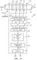
- FIG. 3is a function block diagram of a processing unit of flow measuring system similar to that of FIG. 1 , in accordance with the present invention.
- FIG. 4is a schematic illustration of a flow measuring system for providing a density and/or composition measurement provided by a gamma densitometer augmented for entrained gas within a bitumen froth flow passing within a pipe, in accordance with the present invention.
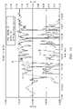
- FIG. 5is a plot of the relative error in the interpreted percent solids versus the gas volume fraction in a bitumen froth flow, in accordance with the present invention.
- FIG. 6is a schematic illustration of a flow measuring system for providing a density and/or composition measurement provided by a Coriolis meter augmented for entrained gas within a bitumen froth flow passing within a pipe, in accordance with the present invention.
- FIG. 7is a function block diagram of a processing unit of a flow measuring system similar to that of FIG. 6 , in accordance with the present invention.
- FIG. 8is a schematic illustration of a model of a Coriolis meter having aerated fluid flowing therethrough that accounts for compressibility and inhomogeniety of the aerated fluid, in accordance with the present invention.
- FIG. 9is a schematic illustration of a well head monitoring system for providing a density and/or composition measurement provided by a Coriolis meter augmented for entrained gas within a bitumen froth flow passing within a pipe, in accordance with the present invention.
- FIG. 10is a plot of three phase composition of an aerated hydrocarbon and water fluid flow as a function of sound speed and flow density, in accordance with the present invention.
- FIG. 11is another embodiment of a function block diagram of a processing unit of a flow measuring system similar to that of FIG. 7 , in accordance with the present invention.
- FIG. 12is a plot of the density correction and gas volume fraction of a fluid determined by a flow system embodying the present invention
- FIG. 13is a plot of net oil error and watercut of three phase fluid flow determined by a flow system embodying the present invention.
- FIG. 14is a plot of a snap shot of three phase fluid flow determined by a flow system embodying the present invention.
- FIG. 15is a schematic block diagram of a gas volume fraction meter, in accordance with the present invention.
- FIG. 16is a schematic block diagram of another embodiment of a gas volume fraction meter, in accordance with the present invention.
- FIG. 17is a k ⁇ plot of data processed from an array of pressure sensors used to measure the speed of sound of a fluid flow passing in a pipe, in accordance with the present invention.
- FIG. 18is a plot of the speed of sound of the fluid flow as a function of the gas volume fraction over a range of different pressures, in accordance with the present invention.
- FIG. 19is a schematic block diagram of a volumetric flow meter having an array of sensors, in accordance with the present invention.
- FIG. 20is a graphical cross-sectional view of the fluid flow propagating through a pipe, in accordance with the present invention.
- FIG. 21is a k ⁇ plot of data processed from an array of pressure sensors used to measure the velocity of a fluid flow passing in a pipe, in accordance with the present invention.
- Density meters 16provide a measurement of the density of a fluid flow 12 passing through a pipe 14 .
- a density meterprovides erroneous density measurements in the presence of entrained gas (e.g., bubbly gas) within the fluid flow.
- the present inventionprovides a means for augmenting or compensating the density meter to determine improved density measurements that provides the density of the non-gas portion of the fluid flow 12 .
- the density metermay be any device capable of measuring the density of the fluid flow, such as nuclear densitometers, vibrating vane densitometers and Coriolis flow meters, which provide a density measurement as a by-product measurement.
- the present inventionproposes the use of sonar-based entrained gas measurements to determine the entrained gas level in conjunction with any density measurement of a mixture flowing in a pipe to improve the accuracy, and therefore value of the density measurement.
- a sound speed based entrained gas measurementcan accurately determine the entrained gas in an aerated mixture without precise knowledge of the composition of either the non-gas components of the multiphase mixture or the composition of gas itself.
- a flow measuring system 10 embodying the present inventionincludes a density meter 16 , a speed of sound (SOS) measuring apparatus 18 and a processing unit 20 to provide any one or more of the following parameters of the fluid flow 12 , namely, gas volume fraction, speed of sound propagating through the fluid flow, uncompensated density, compensated density and composition.
- the fluid flowmay be any aerated fluid or mixture including liquid, slurries, solid/liquid mixture, liquid/liquid mixture, solid/solid mixture and any other multiphase flow having entrained gas.
- the density meter 16provides a signal 22 indicative of the density of the fluid flow 12 not augmented or compensated for entrained gas.
- the SOS measuring apparatus 18provides an SOS signal 24 indicative of the speed of sound propagating through the fluid flow.
- a processing unit 20determines at least one of the parameters of the fluid flow described hereinbefore in response to the SOS signal 24 and density signal 22 .
- Pressure and/or temperature signals 26 , 28may also be provided to the processing unit 20 , which may be used to provide more accurate measurements of the gas volume fraction. The pressure and temperature may be measured by known means or estimated.
- the SOS measuring device 18includes any means for measuring the speed of sound propagating through the aerated flow 12 .
- One methodincludes a pair of ultra-sonic sensors axially spaced along the pipe 14 , wherein the time of flight of an ultrasonic signal propagating between an ultra-sonic transmitter and receiver is indicative of the speed of sound.
- the frequency of the ultra-sonic signalmust be relating low to reduce scatter within the flow.
- the meteris similar as that described in U.S. Pat. No. 7,096,719 issued on Aug. 29, 2006, which is incorporated herein by reference.
- a flow measuring system 30 embodying the present inventionprovides a gas volume fraction (GVF) meter 100 for determining the gas volume fraction of the fluid flow 12 , which will be described in greater detail hereinafter.
- the GVF meter 100comprises a sensing device 116 having a plurality of strain-based or pressure sensors 118 - 121 spaced axially along the pipe for measuring the acoustic pressures 190 propagating through the flow 12 .
- the GVF meterdetermines and provides a first signal 27 indicative of the SOS propagating through the fluid flow 12 and a second signal 29 indicative of the gas volume fraction (GVF) of the flow 12 , which will be described in greater detail hereinafter.
- the gas volume fraction meter 100is similar to that described in U.S. Pat. No. 7,062,976 issued on Jun. 20, 2006, which is incorporated herein by reference.
- the processing unit 32determines at least one of the parameters of the fluid flow described hereinbefore in response to the SOS signal 24 and/or GVF signal 29 , and the density signal 22 .
- FIG. 3illustrates a functional block diagram 40 of the flow measuring system 30 of FIG. 2 .
- the GVF meter 100measures acoustic pressures propagating through the fluids 12 , thereby measuring the speed of sound ⁇ mix propagating through the fluid flow 12 at 42 .
- the GVF meter 100calculates the gas volume fraction of the fluid using the measured speed of sound at 44 .
- the GVF metermay also use the pressure of the process flow to determine the gas volume fraction.
- the pressuremay be measured or estimated at 46 .
- the calculated gas volume fraction 29is provided to the processing unit 32 . Knowing the gas volume fraction 29 (and/or speed of sound 27 propagating through the flow) and the measured density 22 , the processing unit 32 can determine density of the non-gas portion of the multiphase flow 12 .
- the density ( ⁇ mix ) 22 of an aerated flow 12is related to the volumetric phase fraction of the components ( ⁇ i ) and the density of the components ( ⁇ i ).
- ⁇ mixis the density of the mixture
- ⁇ nongas , ⁇ nongasare the density and phase fraction, respectively, of a non-gas component of the fluid flow
- ⁇ gas , ⁇ gasare the density and phase fraction, respectively, of the entrained gas within the mixture.
- knowing the density ( ⁇ gas ) of the gas/air, the measured gas volume fraction of the gas ( ⁇ gas ), and the improved density measurement ( ⁇ mix ) of the aerated flow to be compensated for entrained gasenables the density ( ⁇ nongas ) of the non-gas portion of the aerated flow 12 to be determined, which provides improved compositional information of the aerated flow 12 .
- knowing just the measured density ( ⁇ mix ) 22 of the aerated flow 12 density of the gas component and the gas volume fraction ( ⁇ gas ) 29is sufficient to determine the density ( ⁇ nongas ) 48 of the non-gas component of the flow 12 .
- the present inventionfurther contemplates determining improved compositional information of the aerated flow 12 .
- ⁇ 1[ ⁇ mix ⁇ 2 (1 ⁇ gas )]/( ⁇ 1 ⁇ 2 )
- knowing the density ( ⁇ gas ) of the gas/air and the measured density of the gas volume fraction ( ⁇ gas )enables density measurement ( ⁇ mix ) of the mixture to be compensated for entrained gas and provide a density measurement of only the two-component mixture that does not include the density of the entrained air/gas at 50 .
- one example of an application for the flow measuring system 30is in the oil sands industry, where monitoring entrained sand levels in bitumen/water froths is an important application.
- an accurate measurement of the amount of particlese.g., sand
- a gamma densitometer 60operating on a bitumen froth mixture 12 , which contains a small amount of entrained air and sand particles entrained in a liquid continuous mixture of bitumen and water.
- bitumen and waterare nearly identical for most applications, therefore, variations in the bitumen/water cut of liquid phase has very limited effect on the mixture density. Variations in the mixture density are therefore due to the air and particles.
- the density of the particles ( ⁇ 2 ) and the density of the air ( ⁇ gas )are known.
- the gamma densitometer 60in combination with the entrained gas meter 100 provides a means to determine the amount of sand left ( ⁇ 2 ) in the slurry as well as other parameters of the mixture, as described hereinbefore.
- FIG. 5is a plot of the relative error in interpreted percent of solids in a bitumen froth flow versus the gas fraction of entrained air/gas in the flow 12 . As shown, a bitumen froth flow having 1% of entrained air therein results in an approximately 20% error in percent solids (e.g., sand) in the bitumen froth flow.
- percent solidse.g., sand
- the density measurement ( ⁇ nongas ) and composition measurement ( ⁇ 1 , ⁇ 2 ) described abovecan be done on the full pipe, or as shown in FIG. 6 , on a slip stream pipe 70 .
- a slip stream pipe 70enables the use of a Coriolis meter 72 to measure the density ( ⁇ mix ) by providing a smaller diameter pipe.
- a further benefit of a sonar-based entrained air measurementis achieved when the sound speed measurement is used to enhance the accuracy of the Coriolis on the aerated mixture, similar to that described in U.S. Pat. No. 7,152,460, issued on Dec. 26, 2006, which is incorporated herein by reference. While the entrained gas meter 100 is shown mounted on the full pipe in FIG. 6 , the present invention contemplates that the entrained air meter may be mounted on the slip stream pipe 70 .
- the apparatus 100 for measuring the gas volume fraction of the flow 12may also provide a velocity measurement and a volumetric flow rate measurement of the flow, similar to that described in U.S. Pat. No. 7,400,985 issued on Jul. 15, 2008, U.S. patent application Ser. No. 10/712,833, filed on Nov. 12, 2003, U.S. Pat. No. 7,165,464 issued on Jan. 23, 2007 and U.S. Pat. No. 7,127,360 issued on Oct. 24, 2006, which are incorporated herein by reference.
- Coriolis metersprovide a measurement of the mass flow and/or density of a fluid flow 12 passing through a pipe 14 .
- a Coriolis meterprovides erroneous mass flow and density measurements in the presence of entrained gas within the fluid flow (e.g., bubbly gas).
- the present inventionmay also provide a means for compensating the Coriolis meter to provide corrected or improved density and/or mass flow measurements.
- gas volume fraction meter 100may be used to determine the density of the non-gas component of the flow 12 and the composition of a multi-phase flow 12 as described hereinbefore
- the GVF metermay be also used to compensate or augment the output density measurement and the mass flow measurement of a Coriolis meter, similar to that described in U.S. Pat. No. 7,152,460, issued on Dec. 26, 2006, which is incorporated herein by reference.
- the Coriolis meter 16provides a frequency signal (f nat ) indicative of the natural frequency of the fluid 12 loaded tubes of the Coriolis meter and the phase signal ( ⁇ ) indicative of the phase lag in the tubes of the Coriolis meter.
- the GVF meter 100 or SOS measuring apparatus 18provides an SOS signal 24 indicative of the speed of sound propagating through the fluid flow.
- a processing unit 32processes the frequency signal, the phase signal and the SOS signal to provide at least one of the parameters of the fluid flow described hereinbefore, including the mass flow of the flow 12 .
- Pressure and/or temperature signalsmay also be provided to the processing unit 32 , which may be used to provide more accurate measurements of the gas volume fraction. The pressure and temperature may be measured by known means or estimated.
- the Coriolis metermay be any known coriolis meter, such as two inch bent tube Coriolis meter manufactured by MicroMotion Inc. and a two inch straight tube coriolic meter manufactured by Endress & Hauser Inc.
- the Coriolis meterscomprise a pair of bent tubes (e.g. U-shaped, pretzel shaped) or straight tubes as will be described hereinafter.
- FIG. 7illustrates a functional block diagram 80 of the flow measuring system of FIG. 2 .
- the GVF meter 100measures acoustic pressures propagating through the fluids to measure the speed of sound ⁇ mix .
- the GVF metercalculates at least gas volume fraction of the fluid and/or the reduced natural frequency using the measured speed of sound.
- the GVF metermay also use the pressure of the process flow to determine the gas volume fraction.
- the calculated gas volume fraction and/or reduced frequencyis provided to the processing unit 21 .
- the improved densityis determined using analytically derived or empirically derived density calibration models (or formulas derived therefore), which is a function of the measured natural frequency and at least one of the determined GVF, reduced frequency and speed of sound, or any combination thereof, which will be described in greater detail hereinafter.
- the improved density measurementis the density of the aerated flow passing through the pipe.
- the present inventionfurther contemplates determining improved compositional information of the aerated flow.
- the processing unit 21can determine phase fraction of each component of the multiphase flow.
- the present inventionalso contemplates compensating or improving the mass flow rate measurement of the Coriolis meter 16 , as shown in FIG. 7 .
- the calculated gas volume fraction and/or reduced frequencyis provided to the processing unit 32 .
- the improved mass flow rateis determined using analytically derived or empirically derived mass flow calibration models (or formulas derived therefore), which is a function of the measured phase difference ( ⁇ ) and at least one of the determined GVF, reduced frequency and speed of sound, or any combination thereof, which will be described in greater detail hereinafter.
- the calculated gas volume fraction and/or reduced frequencyis provided to the processing unit 32 .
- the improved densityis determined using analytically derived or empirically derived density calibration/parameter models (or formulas derived therefore), which is a function of the measured natural frequency and at least one of the determined GVF, reduced frequency and speed of sound, or any combination thereof, which will be described in greater detail hereinafter.
- the improved mass flow measurementis the mass flow rate of the aerated flow passing through the pipe.
- the improved mass flow and improved density measurementmay be a function of GVF, SOS and reduced frequency
- the present inventioncontemplates these improved measurements may be a function of other parameters, such a gas damping ⁇ gas .
- the processing unit 32may improve both the density measurement and the density measurement of the Coriolis meter 16
- the inventioncontemplates that the processing may only compensate or improve one of the density and mass flow rate parameters.
- Results for a lumped parameter model of FIG. 8 presented hereinafterconfirm long recognized accuracy degradation of vibrating tube density meters attributed to aeration.
- the modelscan be used to illustrate qualitatively the role of several non-dimensional parameters that govern the performance of the meters in aerated fluids. It can be concluded from these models that gas volume fraction plays a dominant role, with several other parameters including gas damping ⁇ gas and reduced frequency also influencing performance.
- the present inventionprovides an approach in which a speed-of-sound measurement of the process fluid is integrated with the natural frequency measurement of a vibrating tube density meter to form a system with an enhanced ability to operate accurately in aerated fluids.
- speed-of-sound measurementaddresses the effects of aeration on multiple levels with the intent to enable vibrating-tube-based density measurements to continue to report liquid density in the presence of entrained air with accuracy approaching that for a non-aerated liquid.
- the aeration level of the process fluidcan be determined with high accuracy on a real time basis.
- the liquids phaseincludes pure liquids, mixtures of liquids, as well as liquid/solid mixtures.
- a simplified, lumped parameter model for the effects of aeration in vibrating tubesis developed.
- the modelillustrates that the effects of aeration can be attributed to at least two independent mechanisms; 1) the density inhomogeniety of discrete gas bubbles and 2) increased mixture compressibility due to aeration.
- Mixture density and sound speedcan be related to component densities and sound speed through the following mixing rules which are applicable to single phase and well-dispersed mixtures and form the basis for speed-of-sound-based entrained air measurement.
- ⁇ mixis the mixture compressibility
- ⁇ iis the component volumetric phase fraction
- the effect of compressibility of the fluid 12can be incorporated into a lumped parameter model of a vibrating tube as shown schematically in FIG. 8 .
- the stiffness of the springrepresents the compressibility of the fluid. As the compressibility approaches zero, the spring stiffness approaches infinity.
- the effective mass of the fluid 12is proportional to the density of the fluid and the geometry of the flow tube.
- the natural frequency of the first transverse acoustic mode in a circular ductcan be used to estimate an appropriate spring constant for the model
- this frequencycorresponds to a wavelength of an acoustic oscillation of approximately two diameters, i.e., this transverse mode is closely related to a “half wavelength” acoustic resonance of the tube.
- the frequency of the first transverse acoustic modeis quite high compared to the typical structural resonant frequencies of Coriolis meters of 100 Hz; however, the resonant acoustic frequency decreases rapidly with increased levels of entrained air.
- a reduced frequency parameterIn characterizing aeroelastic systems, it is often convenient to define a reduced frequency parameter to gauge the significance of the interaction between coupled dynamic systems.
- a reduced frequencycan be defined as a ratio of the natural frequency of the structural system to that of the fluid dynamic system.
- f structis the natural frequency of the tubes in vacuum
- Dis the diameter of the tubes
- a mixis the sound speed of the process fluid.
- aerationintroduces inhomogeneity to the fluid.
- the first-order effects of the aerationcan be modeled using bubble theory.
- V sphere3 ⁇ ⁇ ⁇ ⁇ + 2 ⁇ ⁇ ⁇ 0 ⁇ V fluid
- the density of the sphereis orders of magnitude below that of the liquid and the velocity of bubble approaches three times that of the fluid.
- a gas bubble of volume fraction ⁇is connected across a fulcrum 42 to a compensating mass of fluid with volume 2 ⁇ , where ⁇ is the gas volume fraction of the flow.
- the fulcrumis rigidly connected to the outer pipe 14 .
- the effects of viscositycan be modeled using a damper connected to restrict the motion of the gas bubble with respect to the rest of the liquid and the tube itself.
- the remaining volume of liquid in the tube cross section (1-3 ⁇ )is filled with an inviscid fluid. In the inviscid limit, the compensating mass of fluid (2 ⁇ ) does not participate in the oscillations, and the velocity of the mass-less gas bubble becomes three times the velocity of the tube.
- the effect of this relative motionis to reduce the effective inertia of the fluid inside the tube to 1-3 ⁇ times that presented by a homogeneous fluid-filled the tube.
- the increased damping constantminimizes the relative motion between the gas bubble and the liquid, and the effective inertia of the aerated fluid approaches 1- ⁇ .
- the effective inertia predicted by this model of an aerated, but incompressible, fluid oscillating within a tubeagrees with those presented by Hemp, et al, (2003) in the limits of high and low viscosities.
- processing unitmay use these models independently or together in a lumped parameter model.
- FIG. 8shows a schematic of a lumped parameter model that incorporates the effects of compressibility and inhomogeniety using the mechanism-specific models developed above.
- ⁇ apparent⁇ liq ⁇ ⁇ ( f s 2 f observed 2 - 1 )
- the level of aerationhas a dominant effect on the difference between actual and apparent mixture density.
- the damping parameter associated with the movement of the gas bubble relative to the fluid within the tube, ⁇ gasis a parameter governing the response of the system to aeration.
- the apparent densityapproaches 1-3 ⁇ , i.e., the meter under reports the density of the aerated mixture by 2 ⁇ .
- the apparent densityapproaches the actual fluid density of 1- ⁇ .
- the influence of compressibilityis a function of gas volume fraction for a range of meters differing only in natural frequency of the tubes.
- the natural frequency of the tubesprimarily through the influence of the reduced frequency of operation at a given level of aeration can significantly influence the relation between the actual and apparent density of an aerated fluid.
- the current state-of-the-artappears to utilize quasi-steady models, and empirical correlations based on quasi-steady models, to relate the measured quantities to the derived fluid parameters.
- This quasi-steady model for the fluid structure interactionsappears to work adequately for most Coriolis meters operating with most industrial process flows.
- the validity of the quasi-steady assumptionwill scale with the reduced frequencies of the vibration of the fluid within the pipe. Under a quasi-steady framework, the higher the reduced frequencies, the less accurate the Coriolis meters become.
- One relevant reduced frequency for the unsteady effects within a Coriolis meteris the reduced frequency based on the vibrational frequency, tube diameter, and process fluid sound speed:
- the two reduced frequenciesare not independent, and are scalar multiples of each other.
- variations in the reduced frequencies aboveare primarily determined by variations in process fluid sound speed.
- the reduced frequencyrepresents the ratio between the time required for sound to propagate over a characteristic length to the time required for the tube to vibrate one cycle. From a performance and accuracy perspective, reduced frequencies serve to capture the importance of unsteadiness in the aeroelastic interaction of the fluid and structure.
- the processcan be modeled as quasi-steady.
- Most analytical models of Coriolis flow metersuse a quasi-steady model for the fluid/structure interaction.
- unsteady effectsbegin to influence the relationship between the measured structural response, i.e. the phase lag in the two legs of the meters and the natural frequency, and the sought fluid parameters, i.e. the mass flow of the fluid and fluid density.
- the inertial load from the fluid on the pipedevelops a slight phase lag that increases with increasing frequency.
- oscillations in the flow velocitycan vary over the length of the pipe, potentially introducing error in the output of the meter. Typical variations in mixture sound speeds due to two phase flow result in significant variations in reduced frequencies.
- the Coriolis meter 16has no direct way to measure the gas volume fraction. It has been suggested to use the measured apparent density of the fluid to estimate the level of entrained air; however, this is problematic since both of the two fundamental measurements, phase difference and natural frequency, are impacted by changes in the reduced frequency of the Coriolis vibration. Secondly, it is unlikely that the gas volume fraction is the only variable influencing the relationship between measured phase difference and mass flow and the measured natural frequency and density. Although gas volume fraction appears to correlate over at least some range of parameters, the physics of the problem suggest that sound speed, via a reduced frequency effect, may have also direct influence on the interpretation as developed above.
- the reduced frequency parameters developed hereinare included in interpreting the relation between the phase difference in the vibrating tubes and the mass flow as well as a direct role in interpreting the natural frequency of the oscillating flow tubes in terms of process fluid density.
- the sound speed measurementcombined with knowledge of process liquid and gas components as well as process temperature and pressure, enables a direct measurement of entrained air as well.
- the reduced frequency parameter and gas volume fractioncan be used as inputs in the interpretation of phase lag in terms of mass flow.
- Coriolis meter performanceis characterized as a function of gas volume fraction. The errors were indeed significant. At 2% entrained air, the Coriolis meter is over reporting mass flow by 15% and under reporting mixture density by 2%. The actual density being reported by the meter, if interpreted as the density of the liquid phase in the meter, would be roughly 4% in error.
- the mass flow erroris parameterized by the sound speed-based gas volume fraction of entrained air.
- This correlationwas then used to correct for the coriolis mass flow for the presence of entrained air.
- the amount of entrained air injected upstream of the Coriolis meterwas varied in small increments such that the total entrained air levels ranged from 0 to 2%.
- the Coriolis meterregisters and significant errors in mass flow (up to 15%) due to entrained air and the gas volume fraction based correlation employed successfully corrects the mass flow errors to within roughly 1% for the demonstration.
- a flow measuring system 82 embodying the present inventionmay be used monitor well heads.
- a basic configuration of a well metering system 84is shown schematically in FIG. 9 .
- This approachaddresses most well head flow conditions and utilizes a two phase separator 86 (e.g., gas/liquid cylindrical cyclone (GLCC) separator) to separate the production stream of a gas/oil/water mixture 12 into a mostly gas stream 88 and a mostly liquid stream 89 .
- GLCCgas/liquid cylindrical cyclone
- the present inventioncontemplates any device that separates the air and liquid components.
- the mostly gas stream 88is fed to a sonar-based flow meter 89 similar as flow meter 90 which will be described in greater detail hereinafter.
- the flow metermeasures the flow rate of the gas and determines the gas volume fraction of the gas fluid.
- the mostly liquid stream 89is fed into a sonar-based flow meter 90 , similar to the meters 18 and 100 of FIGS. 1 and 2 respectively, which measures mixture sound speed and possibly convective velocity to determine the gas volume fraction and the volumetric flow rate, respectively, of the liquid/gas mixture 89 .
- the flow meter 90is similar to that described in U.S. Pat. No. 7,127,360 issued on Oct. 24, 2006, U.S. Pat. No. 7,165,464 issued on Jan. 23, 2007 and U.S. Pat. No. 7,062,976 issued on Jun. 20, 2006, which are incorporated herein by reference.
- the flow 89enters a Coriolis meter 16 .
- a processing unit 92receives the output signals from the flow meter 90 and Coriolis meter 16 to provide the measured outputs shown in FIGS. 3 and 8 .
- the two processing options for measuring the aerated liquid mass flow and densityare presented in FIG. 7 .
- the first methodassumes that the performance of the Coriolis for both mass flow and density can be augmented using the methods described in U.S. Pat. No. 7,152,460 Ser. No. 10/892,886 and U.S. Provisional Patent Application No. 60/539,640 , which are incorporated herein by reference.
- the second approachdescribed in FIG. 11 , assumes that only the density measurement of the Coriolis meter is used for the mass flow and density of the aerated liquid.
- the volumetric flow rate determined by the flow meter 90is combined with the corrected density to determine mass flow when aeration levels (e.g., gas volume fraction) exceed a threshold value.
- aeration levelse.g., gas volume fraction
- the second approachcan be described as follows. To determine the density, the speed of sound (SOS) measurement provided by the flow meter 90 and the pressure (P) measurement provided by a pressure sensor 98 (or may be estimated) are used to calculate gas volume fraction and/or reduced frequency parameter of the Coriolis meter operating on the aerated fluid. Next the mixture density is determined by correcting the output of the Coriolis-based density meter for the effects of aeration (as described in similar to that described in U.S. Pat. No. 7,152,460. Direct measurement of the mixture density along with knowledge of the gas volume fraction and the gas density enables determination of liquid phase density, as described hereinbefore.
- SOSspeed of sound
- Ppressure
- a pressure sensor 98or may be estimated
- Mass flowis determined via one of two methods, depending on the gas volume fraction measurement of the flow meter 90 . As shown in FIG. 11 , if the gas volume fraction measurement is below a predetermined or input threshold level, the mass flow reported by the Coriolis is used. If it is above a threshold, the mass flow is calculated by first determining the total mixture volumetric flow rate by the flow meter 90 and then multiplying this value by corrected mixture density as described above.
- the mostly gas stream 88is feed in a sonar-based flow meter 99 similar to that described hereinbefore and in U.S. Pat. No. 7,127,360 issued Oct. 24, 2006, U.S. Pat. No. 7,165,464 and U.S. Pat. No. 7,062,976.
- the flow meter 99measures sound speed and volumetric flow rate of the gas stream 88 , and optionally an orifice plate may be used to measure the gas stream momentum. Combination of volumetric flow, sound speed and momentum measurements enables a good measurement of gas rate and liquid rate.
- the oil/water cut of the liquid phase of the mostly gas mixturecan be assumed to be the same as the oil/water cut of the mostly liquid stream.
- FIGS. 12-14illustrated data recorded from the Coriolis meter 16 and the flow meter 90 to determine various parameters of the process fluid (e.g., oil/water/gas mixture). Specifically, FIG. 12 shows the density correction of the Coriolis meter 16 . FIG. 13 shows the net oil and water cut of the process fluid. FIG. 14 shows a snapshot of the oil production being pumped from ground.
- the process fluide.g., oil/water/gas mixture
- the sonar-based entrained air meter 16enables Coriolis meters to maintain single phase accuracy in presence of entrained air.
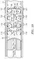
- FIG. 15illustrates a gas volume fraction meter 100 of FIG. 2 , as described herein before.
- the GVF meter 100includes a sensing device 116 disposed on the pipe 14 and a processing unit 124 .
- the sensing device 116comprises an array of strain-based sensors or pressure sensors 118 - 121 for measuring the unsteady pressures produced by acoustic waves propagating through the flow 12 to determine the speed of sound (SOS).
- the pressure signals P 1 (t)-P N (t)are provided to the processing unit 124 , which digitizes the pressure signals and computes the SOS and GVF parameters.
- a cable 113electronically connects the sensing device 116 to the processing unit 124 .
- the analog pressure sensor signals P 1 (t)-P N (t)are typically 4-20 mA current loop signals.
- the array of pressure sensors 118 - 121comprises an array of at least two pressure sensors 118 , 119 spaced axially along the outer surface 122 of the pipe 14 , having a process flow 112 propagating therein.
- the pressure sensors 118 - 121may be clamped onto or generally removably mounted to the pipe by any releasable fastener, such as bolts, screws and clamps. Alternatively, the sensors may be permanently attached to, ported in or integral (e.g., embedded) with the pipe 14 .
- the array of sensors of the sensing device 116may include any number of pressure sensors 118 - 121 greater than two sensors, such as three, four, eight, sixteen or N number of sensors between two and twenty-four sensors.
- the pressure sensors 118 - 119measure the unsteady pressures produced by acoustic waves propagating through the flow, which are indicative of the SOS propagating through the fluid flow 12 in the pipe.
- the output signals (P 1 (t)-P N (t)) of the pressure sensors 118 - 121are provided to a pre-amplifier unit 139 that amplifies the signals generated by the pressure sensors 118 - 121 .
- the processing unit 124processes the pressure measurement data P 1 (t)-P N (t) and determines the desired parameters and characteristics of the flow 12 , as described hereinbefore.
- the apparatus 100also contemplates providing one or more acoustic sources 127 to enable the measurement of the speed of sound propagating through the flow for instances of acoustically quiet flow.
- the acoustic sourcemay be a device that taps or vibrates on the wall of the pipe, for example.
- the acoustic sourcesmay be disposed at the input end of output end of the array of sensors 118 - 121 , or at both ends as shown.
- the passive noiseincludes noise generated by pumps, valves, motors, and the turbulent mixture itself.
- the apparatus 10has the ability to measure the speed of sound (SOS) by measuring unsteady pressures created by acoustical disturbances propagating through the flow 12 . Knowing or estimating the pressure and/or temperature of the flow and the speed of sound of the acoustic disturbances or waves, the processing unit 124 can determine gas volume fraction, such as that described in U.S. Pat. No. 7,359,803, issued Apr. 15, 2008, U.S. Pat. No. 7,032,432 issued Apr. 25, 2006 and U.S. Pat. No. 7,096,976 issued Jun. 20, 2006, which are all incorporated by reference.
- SOSspeed of sound
- an apparatus 200 of FIG. 16 embodying the present inventionhas an array of at least two pressure sensors 118 , 119 , located at two locations x 1 ,x 2 axially along the pipe 14 for sensing respective stochastic signals propagating between the sensors 118 , 119 within the pipe at their respective locations.
- Each sensor 118 , 119provides a signal indicating an unsteady pressure at the location of each sensor, at each instant in a series of sampling instants.
- the sensor arraymay include more than two pressure sensors as depicted by pressure sensor 120 , 121 at location x 3 ,x N .
- the pressure generated by the acoustic pressure disturbancesmay be measured through strained-based sensors and/or pressure sensors 118 - 121 .
- the pressure sensors 118 - 121provide analog pressure time-varying signals P 1 (t),P 2 (t),P 3 (t),P N (t) to the signal processing unit 124 .
- the processing unit 124processes the pressure signals to first provide output signals 151 , 155 indicative of the speed of sound propagating through the flow 12 , and subsequently, provide a GVF measurement in response to pressure disturbances generated by acoustic waves propagating through the flow 12 .
- the processing unit 124receives the pressure signals from the array of sensors 118 - 121 .
- a data acquisition unit 154digitizes pressure signals P 1 (t)-P N (t) associated with the acoustic waves 14 propagating through the pipe 114 .
- An FFT logic 156calculates the Fourier transform of the digitized time-based input signals P 1 (t)-P N (t) and provides complex frequency domain (or frequency based) signals P 1 ( ⁇ ),P 2 ( ⁇ ),P 3 ( ⁇ ),P N ( ⁇ ) indicative of the frequency content of the input signals.
- a data accumulator 158accumulates the additional signals P 1 (t)-P N (t) from the sensors, and provides the data accumulated over a sampling interval to an array processor 160 , which performs a spatial-temporal (two-dimensional) transform of the sensor data, from the xt domain to the k- ⁇ domain, and then calculates the power in the k- ⁇ plane, as represented by a k- ⁇ plot, similar to that provided by the convective array processor 146 .
- the array processor 160determines the wavelength and so the (spatial) wavenumber k, and also the (temporal) frequency and so the angular frequency ⁇ , of various of the spectral components of the stochastic parameter.
- the array processor 160determines the wavelength and so the (spatial) wavenumber k, and also the (temporal) frequency and so the angular frequency ⁇ , of various of the spectral components of the stochastic parameter.
- the power in the k- ⁇ plane shown in a k- ⁇ plot of FIG. 17 so determinedwill exhibit a structure that is called an acoustic ridge 170 , 172 in both the left and right planes of the plot, wherein one of the acoustic ridges 170 is indicative of the speed of sound traveling in one axial direction and the other acoustic ridge 172 being indicative of the speed of sound traveling in the other axial direction.
- the acoustic ridgesrepresent the concentration of a stochastic parameter that propagates through the flow and is a mathematical manifestation of the relationship between the spatial variations and temporal variations described above. Such a plot will indicate a tendency for k- ⁇ pairs to appear more or less along a line 170 , 172 with some slope, the slope indicating the speed of sound.
- the power in the k- ⁇ plane so determinedis then provided to an acoustic ridge identifier 162 , which uses one or another feature extraction method to determine the location and orientation (slope) of any acoustic ridge present in the left and right k- ⁇ plane.
- the velocitymay be determined by using the slope of one of the two acoustic ridges 170 , 172 or averaging the slopes of the acoustic ridges 170 , 172 .
- information including the acoustic ridge orientation (slope)is used by an analyzer 164 to determine the flow parameters relating to measured speed of sound, such as the consistency or composition of the flow, the density of the flow, the average size of particles in the flow, the air/mass ratio of the flow, gas volume fraction of the flow, the speed of sound propagating through the flow, and/or the percentage of entrained air within the flow.
- the flow parameters relating to measured speed of soundsuch as the consistency or composition of the flow, the density of the flow, the average size of particles in the flow, the air/mass ratio of the flow, gas volume fraction of the flow, the speed of sound propagating through the flow, and/or the percentage of entrained air within the flow.
- An array processor 160uses standard so-called beam forming, array processing, or adaptive array-processing algorithms, i.e. algorithms for processing the sensor signals using various delays and weighting to create suitable phase relationships between the signals provided by the different sensors, thereby creating phased antenna array functionality.
- One such technique of determining the speed of sound propagating through the flow 12is using array processing techniques to define an acoustic ridge in the k- ⁇ plane as shown in FIG. 17 .
- the slope of the acoustic ridgeis indicative of the speed of sound propagating through the flow 12 .
- the speed of sound (SOS)is determined by applying sonar arraying processing techniques to determine the speed at which the one dimensional acoustic waves propagate past the axial array of unsteady pressure measurements distributed along the pipe 14 .
- the apparatus 200 of the present inventionmeasures the speed of sound (SOS) of one-dimensional sound waves propagating through the mixture to determine the gas volume fraction of the mixture. It is known that sound propagates through various mediums at various speeds in such fields as SONAR and RADAR fields.
- the speed of sound propagating through the pipe and flow 12may be determined using a number of known techniques, such as those set forth in U.S. Pat. No. 6,354,147; U.S. Pat. No. 7,146,864; U.S. Pat. No. 6,587,798, U.S. Pat. No. 6,732,575 and U.S. Pat. No. 7,062,976, each of which are incorporated herein by reference.
- sonar-based flow meterusing an array of sensors 118 - 121 to measure the speed of sound of an acoustic wave propagating through the mixture is shown and described, one will appreciate that any means for measuring the speed of sound of the acoustic wave may used to determine the entrained gas volume fraction of the mixture/fluid or other characteristics of the flow described hereinbefore.
- the analyzer 164 of the processing unit 124provides output signals indicative of characteristics of the process flow 12 that are related to the measured speed of sound (SOS) propagating through the flow 12 .
- SOSmeasured speed of sound
- the analyzer 164assumes a nearly isothermal condition for the flow 12 .
- xis the speed of sound
- A1+rg/rl*(K eff /P ⁇ 1) ⁇ K eff /P
- BK eff /P ⁇ 2+rg/rl
- C1 ⁇ K eff /rl*a meas ⁇ 2)
- Rggas density
- rlliquid density
- K effeffective K (modulus of the liquid and pipewall)
- Ppressure
- a measmeasured speed of sound.
- the sound speed of a mixturecan be related to volumetric phase fraction ( ⁇ i ) of the components and the sound speed (a) and densities ( ⁇ ) of the component through the Wood equation.
- One dimensional compression waves propagating within a flow 12 contained within a pipe 14exert an unsteady internal pressure loading on the pipe.
- the degree to which the pipe displaces as a result of the unsteady pressure loadinginfluences the speed of propagation of the compression wave.
- the relationship among the infinite domain speed of sound and density of a mixture, the elastic modulus (E), thickness (t), and radius (R) of a vacuum-backed cylindrical conduit, and the effective propagation velocity (a eff ) for one dimensional compressionis given by the following expression:
- the mixing ruleessentially states that the compressibility of a mixture (1/( ⁇ a 2 )) is the volumetrically-weighted average of the compressibilities of the components.
- the compressibility of gas phaseis orders of magnitudes greater than that of the liquid.
- the compressibility of the gas phase and the density of the liquid phaseprimarily determine mixture sound speed, and as such, it is necessary to have a good estimate of process pressure to interpret mixture sound speed in terms of volumetric fraction of entrained gas.
- the effect of process pressure on the relationship between sound speed and entrained air volume fractionis shown in FIG. 18 .
- processing unit 24may be implemented in software (using a microprocessor or computer) and/or firmware, or may be implemented using analog and/or digital hardware, having sufficient memory, interfaces, and capacity to perform the functions described herein.
- FIGS. 2 , 20 and 21show the pressure sensors 118 - 121 disposed on the pipe 14 , separate from the Coriolis meter, the present invention contemplates that the GVF meter 100 may be integrated with the Coriolis meter to thereby provide a single apparatus.
- the pressure sensors 118 - 121may be disposed on one or both of the tubes of the Coriolis meter.
- the flow meter 100may process the array of pressure signals to determine the velocity and/or the volumetric flow of fluid flow 12 .
- the flow meter 100 embodying the present inventionhas an array of at least two pressure sensors 118 , 119 , located at two locations x 1 ,x 2 axially along the pipe 14 for sensing respective stochastic signals propagating between the sensors 118 , 119 within the pipe at their respective locations.
- Each sensor 118 , 119provides a signal indicating an unsteady pressure at the location of each sensor, at each instant in a series of sampling instants.
- the sensor arraymay include more than two pressure sensors as depicted by pressure sensor 120 , 121 at location x 3 ,x N .
- the pressure generated by the convective pressure disturbancesmay be measured through strained-based sensors and/or pressure sensors 118 - 121 .
- the pressure sensors 118 - 121provide analog pressure time-varying signals P 1 (t),P 2 (t),P 3 (t),P N (t) to the signal processing unit 124 .
- the processing unit 24processes the pressure signals to first provide output signals indicative of the pressure disturbances that convect with the flow 12 , and subsequently, provide output signals in response to pressure disturbances generated by convective waves propagating through the flow 12 , such as velocity, Mach number and volumetric flow rate of the process flow 12 .
- the processing unit 24receives the pressure signals from the array of sensors 118 - 121 .
- a data acquisition unit 140e.g., A/D converter
- the FFT logiccalculates the Fourier transform of the digitized time-based input signals P 1 (t)-P N (t) and provides complex frequency domain (or frequency based) signals P 1 ( ⁇ ),P 2 ( ⁇ ),P 3 ( ⁇ ),P N ( ⁇ ) indicative of the frequency content of the input signals.
- any other technique for obtaining the frequency domain characteristics of the signals P 1 ( ⁇ )-P N (t)may be used.
- the cross-spectral density and the power spectral densitymay be used to form one or more frequency domain transfer functions (or frequency responses or ratios) discussed hereinafter.
- One technique of determining the convection velocity of the turbulent eddies 88 within the process flow 12is by characterizing a convective ridge of the resulting unsteady pressures using an array of sensors or other beam forming techniques, similar to that described in U.S. Pat. No. 6,889,562 and U.S. Pat. No. 6,609,069, which are incorporated herein by reference.
- a data accumulator 144accumulates the frequency signals P 1 ( ⁇ )-P N ( ⁇ ) over a sampling interval, and provides the data to an array processor 146 , which performs a spatial-temporal (two-dimensional) transform of the sensor data, from the xt domain to the k- ⁇ domain, and then calculates the power in the k- ⁇ plane, as represented by a k- ⁇ plot.
- the array processor 146uses standard so-called beam forming, array processing, or adaptive array-processing algorithms, i.e. algorithms for processing the sensor signals using various delays and weighting to create suitable phase relationships between the signals provided by the different sensors, thereby creating phased antenna array functionality.
- the prior artteaches many algorithms of use in spatially and temporally decomposing a signal from a phased array of sensors, and the present invention is not restricted to any particular algorithm.
- One particular adaptive array processing algorithmis the Capon method/algorithm. While the Capon method is described as one method, the present invention contemplates the use of other adaptive array processing algorithms, such as the MUSIC algorithm.
- the present inventionrecognizes that such techniques can be used to determine flow rate, i.e. that the signals caused by a stochastic parameter convecting with a flow are time stationary and have a coherence length long enough that it is practical to locate sensor units apart from each other and yet still be within the coherence length.
- uis the convection velocity (flow velocity).
- a plot of k- ⁇ pairsis obtained from a spectral analysis of sensor samples associated with convective parameters.
- the pairingsare portrayed so that the energy of the disturbance spectrally corresponding to the pairings can be described as a substantially straight ridge, a ridge that in turbulent boundary layer theory is called a convective ridge.
- What is being sensedare not discrete events of turbulent eddies, but rather a continuum of possibly overlapping events forming a temporally stationary, essentially white process over the frequency range of interest.
- the convective eddies 88are distributed over a range of length scales and hence temporal frequencies.
- the array processor 146determines the wavelength and so the (spatial) wavenumber k, and also the (temporal) frequency and so the angular frequency ⁇ , of various of the spectral components of the stochastic parameter.
- the array processor 146determines the wavelength and so the (spatial) wavenumber k, and also the (temporal) frequency and so the angular frequency ⁇ , of various of the spectral components of the stochastic parameter.
- the present inventionmay use temporal and spatial filtering to precondition the signals to effectively filter out the common mode characteristics P common mode and other long wavelength (compared to the sensor spacing) characteristics in the pipe 14 by differencing adjacent sensors and retaining a substantial portion of the stochastic parameter associated with the flow field and any other short wavelength (compared to the sensor spacing) low frequency stochastic parameters.
- the power in the k- ⁇ plane shown in a k- ⁇ plot of FIG. 21shows a convective ridge 200 .
- the convective ridgerepresents the concentration of a stochastic parameter that convects with the flow and is a mathematical manifestation of the relationship between the spatial variations and temporal variations described above. Such a plot will indicate a tendency for k- ⁇ pairs to appear more or less along a line 200 with some slope, the slope indicating the flow velocity.
- a convective ridge identifier 148uses one or another feature extraction method to determine the location and orientation (slope) of any convective ridge 200 present in the k- ⁇ plane.
- a so-called slant stacking methodis used, a method in which the accumulated frequency of k- ⁇ pairs in the k- ⁇ plot along different rays emanating from the origin are compared, each different ray being associated with a different trial convection velocity (in that the slope of a ray is assumed to be the flow velocity or correlated to the flow velocity in a known way).
- the convective ridge identifier 148provides information about the different trial convection velocities, information referred to generally as convective ridge information.
- the pressure sensorsincluding electrical strain gages, optical fibers and/or gratings among others as described herein, may be attached to the pipe by adhesive, glue, epoxy, tape or other suitable attachment means to ensure suitable contact between the sensor and the pipe.
- the sensorsmay alternatively be removable or permanently attached via known mechanical techniques such as mechanical fastener, spring loaded, clamped, clam shell arrangement, strapping or other equivalents.
- the strain gages, including optical fibers and/or gratingsmay be embedded in a composite pipe. If desired, for certain applications, the gratings may be detached from (or strain or acoustically isolated from) the pipe if desired.
- any other strain sensing techniquemay be used to measure the variations in strain in the pipe, such as highly sensitive piezoelectric, electronic or electric, strain gages attached to or embedded in the pipe. Accelerometers may be also used to measure the unsteady pressures. Also, other pressure sensors may be used, as described in a number of the aforementioned patents, which are incorporated herein by reference.
- the senormay comprise of piezofilm or strips (e.g. PVDF) as described in at least one of the aforementioned patent applications.
- the inventioncontemplates any number of sensors in the array as taught in at least one of the aforementioned patent applications. Also the invention contemplates that the array of sensors may be mounted or integrated with a tube of a Coriolis meter having shape, such as pretzel shape, U-shaped (as shown), straight tube and any curved shape.
- the inventionfurther contemplates providing an elongated, non-vibrating (or oscillating) portion that permits a greater number of sensors to be used in the array.
- While the present inventiondescribes an array of sensors for measuring the speed of sound propagating through the flow for use in interpreting the relationship between Coriolis forces and the mass flow through a Coriolis meter.
- an ultrasonic devicecould be used to determine speed of sound of the fluid entering. It should be noted that the theory indicates that the interpretation of Coriolis meters will be improved for all fluids if the sound speed of the process fluid is measured and used in the interpretation. Thus, knowing that the sound speed of the fluid is 5000 ft/sec as it would be for a water like substance, compared to 1500 ft/sec as it would be for say supercritical ethylene, would improve the performance of a Coriolis based flow and density measurement. These measurements could be performed practically using existing ultrasonic meters.
- Another approach to determine speed of sound of the fluidsis to measure the resonant frequency of the acoustic modes of the flow tubes.
- the cross sectional area changes associated with the transition from the pipe into the typically much smaller flow tubescreates a significant change in acoustic impedance.
- the flow tubeact as somewhat of a resonant cavity.
- By tracking the resonant frequency of this cavityone could determine the speed of sound of the fluid occupying the cavity. This could be performed with a single pressure sensitive device, mounted either on the Coriolis meter, or on the piping network attached to the Coriolis meter.
- the present inventioncontemplates the ability to augment the performance of a Coriolis meter using any method or means for measuring the gas volume fraction of the fluid flow.
- each of the pressure sensors 118 - 121may include a piezoelectric film sensor to measure the unsteady pressures of the fluid flow 12 using either technique described hereinbefore.
- the piezoelectric film sensorsinclude a piezoelectric material or film to generate an electrical signal proportional to the degree that the material is mechanically deformed or stressed.
- the piezoelectric sensing elementis typically conformed to allow complete or nearly complete circumferential measurement of induced strain to provide a circumferential-averaged pressure signal.
- the sensorscan be formed from PVDF films, co-polymer films, or flexible PZT sensors, similar to that described in “Piezo Film Sensors Technical Manual” provided by Measurement Specialties, Inc., which is incorporated herein by reference.
- a piezoelectric film sensor that may be used for the present inventionis part number 1-1002405-0, LDT4-028K, manufactured by Measurement Specialties, Inc.
- Piezoelectric filmlike piezoelectric material, is a dynamic material that develops an electrical charge proportional to a change in mechanical stress. Consequently, the piezoelectric material measures the strain induced within the pipe 14 due to unsteady pressure variations (e.g., acoustic waves) within the process mixture 12 . Strain within the pipe is transduced to an output voltage or current by the attached piezoelectric sensor.
- the piezoelectrical material or filmmay be formed of a polymer, such as polarized fluoropolymer, polyvinylidene fluoride (PVDF).
- PVDFpolyvinylidene fluoride
- Another embodiment of the present inventionincludes a pressure sensor such as pipe strain sensors, accelerometers, velocity sensors or displacement sensors, discussed hereinafter, that are mounted onto a strap to enable the pressure sensor to be clamped onto the pipe.
- the sensorsmay be removable or permanently attached via known mechanical techniques such as mechanical fastener, spring loaded, clamped, clam shell arrangement, strapping or other equivalents. These certain types of pressure sensors may be desirable for the pipe 12 to exhibit a certain amount of pipe compliance.
- two or more pressure sensorsmay be used around the circumference of the pipe 12 at each of the axial locations.
- the signals from the pressure sensors around the circumference at a given axial locationmay be averaged to provide a cross-sectional (or circumference) averaged unsteady acoustic pressure measurement.
- Other numbers of acoustic pressure sensors and annular spacingmay be used. Averaging multiple annular pressure sensors reduces noises from disturbances and pipe vibrations and other sources of noise not related to the one-dimensional acoustic pressure waves in the pipe 12 , thereby creating a spatial array of pressure sensors to help characterize the one-dimensional sound field within the pipe 12 .
- the pressure sensors 118 - 121 of FIG. 20 described hereinmay be any type of pressure sensor, capable of measuring the unsteady (or ac or dynamic) pressures within a pipe 14 , such as piezoelectric, optical, capacitive, resistive (e.g., Wheatstone bridge), accelerometers (or geophones), velocity measuring devices, displacement measuring devices, etc. If optical pressure sensors are used, the sensors 118 - 121 may be Bragg grating based pressure sensors, such as that described in U.S. Pat. No. 6,016,702, and in U.S. Pat. No. 6,959,604, which are incorporated herein by reference.
- fiber opticsas the pressure sensors 14 they may be connected individually or may be multiplexed along one or more optical fibers using wavelength division multiplexing (WDM), time division multiplexing (TDM), or any other optical multiplexing techniques.
- WDMwavelength division multiplexing
- TDMtime division multiplexing
- a piezo-electronic pressure transducermay be used as one or more of the pressure sensors 115 - 118 and it may measure the unsteady (or dynamic or ac) pressure variations inside the pipe or tube 14 by measuring the pressure levels inside of the tube. These sensors may be ported within the pipe to make direct contact with the mixture 12 .
- the sensors 14comprise pressure sensors manufactured by PCB Piezotronics. In one pressure sensor there are integrated circuit piezoelectric voltage mode-type sensors that feature built-in microelectronic amplifiers, and convert the high-impedance charge into a low-impedance voltage output.
- Model 106 B manufactured by PCB Piezotronicswhich is a high sensitivity, acceleration compensated integrated circuit piezoelectric quartz pressure sensor suitable for measuring low pressure acoustic phenomena in hydraulic and pneumatic systems. It has the unique capability to measure small pressure changes of less than 0.001 psi under high static conditions.
- the 106 Bhas a 300 mV/psi sensitivity and a resolution of 91 dB (0.0001 psi).
- the pressure sensorsincorporate a built-in MOSFET microelectronic amplifier to convert the high-impedance charge output into a low-impedance voltage signal.
- the sensoris powered from a constant-current source and can operate over long coaxial or ribbon cable without signal degradation.
- the low-impedance voltage signalis not affected by triboelectric cable noise or insulation resistance-degrading contaminants.
- Power to operate integrated circuit piezoelectric sensorsgenerally takes the form of a low-cost, 24 to 27 VDC, 2 to 20 mA constant-current supply.
- a data acquisition system of the present inventionmay incorporate constant-current power for directly powering integrated circuit piezoelectric sensors.
- piezoelectric pressure sensorsare constructed with either compression mode quartz crystals preloaded in a rigid housing, or unconstrained tourmaline crystals. These designs give the sensors microsecond response times and resonant frequencies in the hundreds of kHz, with minimal overshoot or ringing. Small diaphragm diameters ensure spatial resolution of narrow shock waves.
- the output characteristic of piezoelectric pressure sensor systemsis that of an AC-coupled system, where repetitive signals decay until there is an equal area above and below the original base line. As magnitude levels of the monitored event fluctuate, the output remains stabilized around the base line with the positive and negative areas of the curve remaining equal.
- any strain sensing techniquemay be used to measure the variations in strain in the pipe, such as highly sensitive piezoelectric, electronic or electric, strain gages and piezo-resistive strain gages attached to the pipe 12 .
- Other strain gagesinclude resistive foil type gages having a race track configuration similar to that disclosed U.S. Pat. No. 6,354,147, which is incorporated herein by reference.
- the inventionalso contemplates strain gages being disposed about a predetermined portion of the circumference of pipe 12 . The axial placement of and separation distance ⁇ X 1 , ⁇ X 2 between the strain sensors are determined as described hereinabove.
- any other strain sensing techniquemay be used to measure the variations in strain in the tube, such as highly sensitive piezoelectric, electronic or electric, strain gages attached to or embedded in the tube 14 .
- the Coriolis meter described hereinbeforemay be any known Coriolis meter, such as two inch bent tube Coriolis meter manufactured by MicroMotion Inc. and a two inch straight tube coriolic meter manufactured by Endress & Hauser Inc.
- the Coriolis meterscomprise a pair of bent tubes (e.g. U-shaped, pretzel shaped) or straight tubes.
- the present inventioncontemplates any density meter may be used in the embodiments. Similarly, while a particular meter was provided to determine speed of sound propagating through the fluid flow 12 , the present invention contemplates any SOS measuring device may be used.
- any of the embodiments described hereinare merely for illustrative purposes and, as such, any other dimensions and/or geometries may be used if desired, depending on the application, size, performance, manufacturing requirements, or other factors, in view of the teachings herein.
Landscapes
- Physics & Mathematics (AREA)
- General Physics & Mathematics (AREA)
- Fluid Mechanics (AREA)
- Health & Medical Sciences (AREA)
- Life Sciences & Earth Sciences (AREA)
- Chemical & Material Sciences (AREA)
- Analytical Chemistry (AREA)
- Biochemistry (AREA)
- General Health & Medical Sciences (AREA)
- Immunology (AREA)
- Pathology (AREA)
- Measuring Volume Flow (AREA)
Abstract
Description
ρmix=ρnongasφnongas+ρgasφgas
therefore, ρnongas=(ρmix−ρgasφgas)/φnongas=(ρmix−ρgasφgas)/1−φgas, wherein φnongas=1−φgas.
ρnongas=ρmix/(1−φgas)
ρmix=ρ1φ1+ρ2φ2+ρgasφgas
therefore, φ1=[ρmix−ρgasφgas−ρ2(1−φgas)]/(ρ1−ρ2), where φ2=1−φ1−φgas
φ1=[ρmix−ρ2(1−φgas)]/(ρ1−ρ2)
| TABLE 1 |
| Definition of Non-dimensional Parameters Governing the |
| Equation of Motion for the Lumped Parameter Model of |
| a Tube Filled with a Compressible, Aerated Fluid |
| Symbol | Description | Definition |
| α | Mass ratio | mfluid/mstruct |
| Q | Natural Frequency Ratio | ωfluid/ωstruct |
| ζf | Critical Damping Ratio of Fluid System | bfluid/(2mfluidωfluid) |
| ζs | Critical Damping Ratio of Structural | bstruct/(2mstructωsstruc) |
| System | ||
| ζg | Critical Damping Ratio of Structural | bgas/(2mfluidωstruct) |
| System | ||
| τ | Non-dimensional time | t ωstruct |
| y | Non-dimensional temporal derivative of x | dx/dτ |
| TABLE 2 |
| Parameters Defining the Baseline Vibrating Tube Density Meter |
| Param- | ||
| eter | Description | Value |
| fs | Structural Frequency of | 100 Hz |
| α | Mass ratio | 1.25 |
| ζstruct | Critical Damping Ratio - | 0.01 |
| structure | ||
| ζfluid | Critical Damping Ratio - fluid | 0.01 |
| ζgas | Critical Damping Ratio - gas | 0.01 |
| Q | Frequency Ratio | As determined by sound speed |
| of air/water at STP and | ||
| structural parameters | ||
| D | Tube diameter | 1.0 inches |
Mass Factor=0.0147gvf^3−0.0018gvf^2+0.0041gvf+1.0009
Ax2+Bx+C=0
Gas Volume Fraction (GVF)=(−B+sqrt(B^2-4*A*C))/(2*A)
k=ω/u,
Claims (17)
Gas Phase Fraction=−B+sqrt(B^2−4*A*C))/(2*A)
ρmix=ρ1φ1+ρ2φ2+ρgasφgas; and
φgas+φ1+φ2=1
Priority Applications (1)
| Application Number | Priority Date | Filing Date | Title |
|---|---|---|---|
| US11/599,250US7596987B2 (en) | 2003-07-15 | 2006-11-13 | Apparatus and method for providing a density measurement augmented for entrained gas |
Applications Claiming Priority (15)
| Application Number | Priority Date | Filing Date | Title |
|---|---|---|---|
| US48783203P | 2003-07-15 | 2003-07-15 | |
| US49186003P | 2003-08-01 | 2003-08-01 | |
| US50333403P | 2003-09-16 | 2003-09-16 | |
| US50478503P | 2003-09-22 | 2003-09-22 | |
| US51030203P | 2003-10-10 | 2003-10-10 | |
| US51279403P | 2003-10-20 | 2003-10-20 | |
| US52496403P | 2003-11-25 | 2003-11-25 | |
| US53964004P | 2004-01-28 | 2004-01-28 | |
| US54821504P | 2004-02-27 | 2004-02-27 | |
| US57032104P | 2004-05-12 | 2004-05-12 | |
| US57190304P | 2004-05-17 | 2004-05-17 | |
| US57944804P | 2004-06-14 | 2004-06-14 | |
| US10/892,886US7152460B2 (en) | 2003-07-15 | 2004-07-15 | Apparatus and method for compensating a coriolis meter |
| US10/909,593US7134320B2 (en) | 2003-07-15 | 2004-08-02 | Apparatus and method for providing a density measurement augmented for entrained gas |
| US11/599,250US7596987B2 (en) | 2003-07-15 | 2006-11-13 | Apparatus and method for providing a density measurement augmented for entrained gas |
Related Parent Applications (1)
| Application Number | Title | Priority Date | Filing Date |
|---|---|---|---|
| US10/909,593ContinuationUS7134320B2 (en) | 2003-07-15 | 2004-08-02 | Apparatus and method for providing a density measurement augmented for entrained gas |
Publications (2)
| Publication Number | Publication Date |
|---|---|
| US20080223129A1 US20080223129A1 (en) | 2008-09-18 |
| US7596987B2true US7596987B2 (en) | 2009-10-06 |
Family
ID=46302464
Family Applications (2)
| Application Number | Title | Priority Date | Filing Date |
|---|---|---|---|
| US10/909,593Expired - LifetimeUS7134320B2 (en) | 2003-07-15 | 2004-08-02 | Apparatus and method for providing a density measurement augmented for entrained gas |
| US11/599,250Expired - LifetimeUS7596987B2 (en) | 2003-07-15 | 2006-11-13 | Apparatus and method for providing a density measurement augmented for entrained gas |
Family Applications Before (1)
| Application Number | Title | Priority Date | Filing Date |
|---|---|---|---|
| US10/909,593Expired - LifetimeUS7134320B2 (en) | 2003-07-15 | 2004-08-02 | Apparatus and method for providing a density measurement augmented for entrained gas |
Country Status (1)
| Country | Link |
|---|---|
| US (2) | US7134320B2 (en) |
Cited By (14)
| Publication number | Priority date | Publication date | Assignee | Title |
|---|---|---|---|---|
| US8569430B2 (en) | 2009-12-09 | 2013-10-29 | Georgia-Pacific Chemicals Llc | Method of spray drying phenol-formaldehyde resin |
| US20140047827A1 (en)* | 2012-08-15 | 2014-02-20 | Caterpillar Inc. | Aeration in liquid reservoirs |
| US20140126325A1 (en)* | 2012-11-02 | 2014-05-08 | Silixa Ltd. | Enhanced seismic surveying |
| US9346926B2 (en) | 2013-03-14 | 2016-05-24 | Georgia-Pacific Chemicals Llc | High flow urea-formaldehyde powders for particleboard and fiberboard manufacture |
| US9410422B2 (en) | 2013-09-13 | 2016-08-09 | Chevron U.S.A. Inc. | Alternative gauging system for production well testing and related methods |
| US9752911B2 (en) | 2014-12-29 | 2017-09-05 | Concentric Meter Corporation | Fluid parameter sensor and meter |
| US9896929B2 (en) | 2012-11-02 | 2018-02-20 | Silixa Ltd. | Acoustic illumination for flow-monitoring |
| US10107784B2 (en) | 2014-12-29 | 2018-10-23 | Concentric Meter Corporation | Electromagnetic transducer |
| US10126266B2 (en) | 2014-12-29 | 2018-11-13 | Concentric Meter Corporation | Fluid parameter sensor and meter |
| US20200124570A1 (en)* | 2011-10-18 | 2020-04-23 | John Biesak | Method and apparatus for providing real time air measurement applications in wet concrete using dual frequency techniques |
| US10890563B2 (en) | 2016-11-11 | 2021-01-12 | Schlumberger Technology Corporation | Downhole tool with an ultrasonic probe for measuring fluid flow properties |
| US10989047B2 (en)* | 2019-05-10 | 2021-04-27 | Halliburton Energy Services, Inc. | Systems and methods for sand flow detection and quantification |
| WO2022066758A1 (en) | 2020-09-22 | 2022-03-31 | Expro Meters, Inc. | Speed of sound and convective velocity augmented coriolis meters with drive gain limit logic |
| US11940309B2 (en) | 2020-05-15 | 2024-03-26 | Expro Meters, Inc. | Method for determining a fluid flow parameter within a vibrating tube |
Families Citing this family (81)
| Publication number | Priority date | Publication date | Assignee | Title |
|---|---|---|---|---|
| US7784360B2 (en) | 1999-11-22 | 2010-08-31 | Invensys Systems, Inc. | Correcting for two-phase flow in a digital flowmeter |
| US8447534B2 (en) | 1997-11-26 | 2013-05-21 | Invensys Systems, Inc. | Digital flowmeter |
| US8467986B2 (en) | 1997-11-26 | 2013-06-18 | Invensys Systems, Inc. | Drive techniques for a digital flowmeter |
| US7354141B2 (en)* | 2001-12-04 | 2008-04-08 | Labcyte Inc. | Acoustic assessment of characteristics of a fluid relevant to acoustic ejection |
| US7165464B2 (en)* | 2002-11-15 | 2007-01-23 | Cidra Corporation | Apparatus and method for providing a flow measurement compensated for entrained gas |
| DE602004029008D1 (en)* | 2003-01-13 | 2010-10-21 | Expro Meters Inc | APPARATUS AND METHOD FOR DETERMINING THE SPEED OF A FLUID IN A PIPE USING ULTRASONIC SENSORS |
| US20060048583A1 (en)* | 2004-08-16 | 2006-03-09 | Gysling Daniel L | Total gas meter using speed of sound and velocity measurements |
| US6945095B2 (en)* | 2003-01-21 | 2005-09-20 | Weatherford/Lamb, Inc. | Non-intrusive multiphase flow meter |
| US7059199B2 (en)* | 2003-02-10 | 2006-06-13 | Invensys Systems, Inc. | Multiphase Coriolis flowmeter |
| US7188534B2 (en) | 2003-02-10 | 2007-03-13 | Invensys Systems, Inc. | Multi-phase coriolis flowmeter |
| US7134320B2 (en)* | 2003-07-15 | 2006-11-14 | Cidra Corporation | Apparatus and method for providing a density measurement augmented for entrained gas |
| WO2005010470A2 (en)* | 2003-07-15 | 2005-02-03 | Cidra Corporation | An apparatus and method for compensating a coriolis meter |
| US7299705B2 (en)* | 2003-07-15 | 2007-11-27 | Cidra Corporation | Apparatus and method for augmenting a Coriolis meter |
| US7237440B2 (en) | 2003-10-10 | 2007-07-03 | Cidra Corporation | Flow measurement apparatus having strain-based sensors and ultrasonic sensors |
| US7426852B1 (en) | 2004-04-26 | 2008-09-23 | Expro Meters, Inc. | Submersible meter for measuring a parameter of gas hold-up of a fluid |
| US7363800B2 (en)* | 2004-05-17 | 2008-04-29 | Cidra Corporation | Apparatus and method for measuring compositional parameters of a mixture |
| WO2006112878A2 (en) | 2004-09-16 | 2006-10-26 | Cidra Corporation | Apparatus and method for providing a fluid cut measurement of a multi-liquid mixture compensated for entrained gas |
| US7389687B2 (en)* | 2004-11-05 | 2008-06-24 | Cidra Corporation | System for measuring a parameter of an aerated multi-phase mixture flowing in a pipe |
| US7597008B2 (en)* | 2004-11-30 | 2009-10-06 | Micro Motion, Inc. | Method and apparatus for determining flow pressure using density information |
| US7725270B2 (en)* | 2005-03-10 | 2010-05-25 | Expro Meters, Inc. | Industrial flow meter having an accessible digital interface |
| WO2006121480A2 (en)* | 2005-05-10 | 2006-11-16 | Agar Corporation Ltd. | Method and apparatus for measuring multi-streams and multi-phase flow |
| WO2006130499A2 (en)* | 2005-05-27 | 2006-12-07 | Cidra Corporation | An apparatus and method for fiscal measuring of an aerated fluid |
| US7526966B2 (en) | 2005-05-27 | 2009-05-05 | Expro Meters, Inc. | Apparatus and method for measuring a parameter of a multiphase flow |
| ATE526562T1 (en)* | 2005-07-07 | 2011-10-15 | Cidra Corp | WET GAS MEASUREMENT USING A DIFFERENTIAL PRESSURE BASED FLOW METER WITH A SONAR BASED FLOW METER |
| US7603916B2 (en) | 2005-07-07 | 2009-10-20 | Expro Meters, Inc. | Wet gas metering using a differential pressure and a sonar based flow meter |
| US20070055464A1 (en)* | 2005-08-17 | 2007-03-08 | Gysling Daniel L | System and method for providing a compositional measurement of a mixture having entrained gas |
| US7406878B2 (en)* | 2005-09-27 | 2008-08-05 | Endress + Hauser Flowtec Ag | Method for measuring a medium flowing in a pipeline and measurement system therefor |
| DE102005046319A1 (en)* | 2005-09-27 | 2007-03-29 | Endress + Hauser Flowtec Ag | Two or multi-phase medium e.g. fluid`s, physical flow parameter e.g. flow rate, measuring method, involves producing measurement values representing parameter by considering pressure difference of medium and by usage of transfer function |
| US7660689B2 (en)* | 2006-05-08 | 2010-02-09 | Invensys Systems, Inc. | Single and multiphase fluid measurements |
| US7401530B2 (en)* | 2006-05-11 | 2008-07-22 | Weatherford/Lamb, Inc. | Sonar based multiphase flowmeter |
| WO2007136788A2 (en)* | 2006-05-16 | 2007-11-29 | Cidra Corporation | Apparatus and method for determining a parameter in a wet gas flow |
| US7624650B2 (en) | 2006-07-27 | 2009-12-01 | Expro Meters, Inc. | Apparatus and method for attenuating acoustic waves propagating within a pipe wall |
| CN101578503B (en)* | 2006-08-28 | 2014-02-12 | 因万西斯系统股份有限公司 | Wet gas measurement |
| US7617055B2 (en) | 2006-08-28 | 2009-11-10 | Invensys Systems, Inc. | Wet gas measurement |
| US7624651B2 (en)* | 2006-10-30 | 2009-12-01 | Expro Meters, Inc. | Apparatus and method for attenuating acoustic waves in pipe walls for clamp-on ultrasonic flow meter |
| US7673526B2 (en)* | 2006-11-01 | 2010-03-09 | Expro Meters, Inc. | Apparatus and method of lensing an ultrasonic beam for an ultrasonic flow meter |
| EP2092278A2 (en) | 2006-11-09 | 2009-08-26 | Expro Meters, Inc. | Apparatus and method for measuring a fluid flow parameter within an internal passage of an elongated body |
| US8855948B2 (en)* | 2007-04-20 | 2014-10-07 | Invensys Systems, Inc. | Wet gas measurement |
| US8892371B2 (en)* | 2007-04-20 | 2014-11-18 | Invensys Systems, Inc. | Wet gas measurement |
| US8229686B2 (en)* | 2007-06-28 | 2012-07-24 | Expro Meters, Inc. | Apparatus and method for measuring liquid and gas flow rates in a stratified multi-phase flow |
| AU2007357101B2 (en)* | 2007-07-30 | 2011-08-18 | Micro Motion, Inc. | Flow meter system and method for measuring flow characteristics of a three phase flow |
| US8061186B2 (en)* | 2008-03-26 | 2011-11-22 | Expro Meters, Inc. | System and method for providing a compositional measurement of a mixture having entrained gas |
| BRPI0912364B1 (en)* | 2008-05-09 | 2020-03-10 | Cidra Corporate Services, Inc | SONAR BASE VF / GVF MEASUREMENT APPLICATIONS FOR INDUSTRIAL PROCESSING |
| EP2296724B1 (en)* | 2008-05-20 | 2019-12-25 | Cidra Corporate Services, Inc. | Applications of pump performance monitoring |
| US8739637B2 (en) | 2009-01-30 | 2014-06-03 | Cidra Corporate Services Inc. | Applications for real-time mass ratio, mass flow and particle size measurement of particle laden flows |
| ES2837632T3 (en) | 2009-02-13 | 2021-07-01 | Cidra Corporate Services Inc | Use of gas void fraction measurement in closed-loop control of a fermentation procedure |
| US10394207B2 (en) | 2009-06-12 | 2019-08-27 | CiDRA Corporate Service Inc. | Techniques for optimizing performance of cyclones |
| CA2770214C (en) | 2009-08-11 | 2017-08-15 | Cidra Corporate Services Inc. | Performance monitoring of individual hydrocyclones using sonar-based slurry flow measurement |
| CA2792242C (en) | 2010-03-09 | 2020-12-08 | Cidra Corporate Services Inc. | Method and apparatus for determining gvf (gas volume fraction) for aerated fluids and liquids in flotation tanks, columns, drums, tubes, vats |
| US9977007B2 (en) | 2010-03-09 | 2018-05-22 | Cidra Corporate Services, Inc. | Bubble size determination based on bubble stiffness |
| AT11708U3 (en)* | 2010-10-21 | 2012-03-15 | Avl List Gmbh | METHOD FOR DETERMINING THE MASS FLOW OF GASES, IN PARTICULAR THE EXHAUST OF INTERNAL COMBUSTION ENGINES |
| CA2826655C (en) | 2011-02-04 | 2018-09-18 | Cidra Corporate Services Inc. | Sonic filter for measuring and capturing particles having a particular particle size in a fluid, mixture or process flow |
| WO2012154237A1 (en) | 2011-02-04 | 2012-11-15 | Cidra Corporate Services Inc. | Optimizing acoustic efficiency of a sonic filter or separator |
| US8701461B2 (en)* | 2011-02-22 | 2014-04-22 | Southern Methodist University | Calibration tube for multiphase flowmeters |
| JP5797333B2 (en)* | 2011-06-08 | 2015-10-21 | マイクロ モーション インコーポレイテッド | Method and apparatus for determining and controlling the static pressure of a fluid flowing through a vibrating meter |
| RU2478195C1 (en)* | 2011-09-16 | 2013-03-27 | Федеральное государственное унитарное предприятие федеральный научно-производственный центр "Научно-исследовательский институт измерительных систем им. Ю.Е. Седакова" | Method of prompt determination of compressibility coefficient of gases and their mixtures |
| US11269361B2 (en) | 2011-10-05 | 2022-03-08 | Cidra Corporate Services Inc. | Method and apparatus for using velocity profile measurements in recovering bitumen from a coarse tailings line |
| US10228706B2 (en) | 2011-10-05 | 2019-03-12 | Cidra Corporate Services Inc. | Method and apparatus for using velocity profile measurements in recovering bitumen from a coarse tailings line |
| US10088454B2 (en) | 2011-10-18 | 2018-10-02 | Cidra Corporate Services, Inc. | Speed of sound and/or density measurement using acoustic impedance |
| CA2852678C (en) | 2011-10-18 | 2020-07-07 | Cidra Corporate Services Inc. | Method and apparatus for providing real time air measurement applications in wet concrete |
| WO2013152302A1 (en) | 2012-04-05 | 2013-10-10 | Cidra Corporate Services Inc. | Speed of sound and/or density measurement using acoustic impedance |
| KR101775588B1 (en)* | 2012-03-13 | 2017-09-06 | 마이크로 모우션, 인코포레이티드 | Indirect mass flow sensor |
| EP2667176B1 (en)* | 2012-05-24 | 2015-02-25 | Air Products And Chemicals, Inc. | Apparatus for measuring the true contents of a cylinder of gas under pressure |
| KR101948561B1 (en)* | 2012-08-01 | 2019-02-15 | 마이크로 모우션, 인코포레이티드 | Fluid characteristic determination of a multi-component fluid with compressible and incompressible components |
| US20140202240A1 (en)* | 2013-01-24 | 2014-07-24 | Halliburton Energy Services, Inc. | Flow velocity and acoustic velocity measurement with distributed acoustic sensing |
| US10247840B2 (en) | 2013-01-24 | 2019-04-02 | Halliburton Energy Services, Inc. | Optical well logging |
| US9608627B2 (en) | 2013-01-24 | 2017-03-28 | Halliburton Energy Services | Well tool having optical triggering device for controlling electrical power delivery |
| DE102013006542B4 (en)* | 2013-04-16 | 2017-03-23 | Dräger Safety AG & Co. KGaA | Measuring device, reaction carrier and measuring method |
| EP3254065B1 (en) | 2015-02-05 | 2020-05-06 | Cidra Corporate Services, Inc. | Fluid flow characteristics in a channelizing process flowstream, by inducing a standing wave therein |
| CN107636427B (en)* | 2015-03-04 | 2021-04-02 | 高准公司 | Flow meter measurement confidence determining device and method |
| GB201700428D0 (en)* | 2017-01-10 | 2017-02-22 | Able Instr & Controls Ltd | Apparatus and method for flare flow measurement |
| EP3673265A4 (en) | 2017-08-22 | 2021-05-26 | Cidra Corporate Services, Inc. | METHOD AND DEVICE FOR USE OF REAL-TIME AIR MEASURING DEVICES IN FRESH CONCRETE |
| GB2572836B (en)* | 2018-09-13 | 2020-09-02 | M-Flow Tech Ltd | Void fraction calibration method |
| CN109395671B (en)* | 2018-11-28 | 2023-08-25 | 南京浦世环境科技发展有限公司 | Bypass monitoring device for gas-liquid-solid three-phase reaction and application of bypass monitoring device in carbon dioxide mineral sealing |
| US12049023B2 (en) | 2019-05-10 | 2024-07-30 | Gcp Applied Technologies Inc. | Instrument for direct measurement of air content in a liquid using a resonant electroacoustic transducer |
| US11796366B2 (en)* | 2019-06-24 | 2023-10-24 | Covera Llc | Coriolis meter |
| JP2023500266A (en)* | 2019-11-01 | 2023-01-05 | マイクロ モーション インコーポレイテッド | Improved Supercritical Fluid Measurement Using Vibrating Sensors |
| DE102019135320A1 (en)* | 2019-12-19 | 2021-06-24 | Endress + Hauser Flowtec Ag | Method for measuring the flow of a medium on the basis of a differential pressure measurement |
| EP4232810A4 (en)* | 2020-10-20 | 2024-10-23 | Corvera LLC | DEVICE AND METHOD FOR MEASURING THE SOUND VELOCITY AND DENSITY OF A LIQUID |
| RU2768242C1 (en)* | 2021-03-09 | 2022-03-23 | Российская Федерация, от имени которой выступает Государственная корпорация по атомной энергии "Росатом" (Госкорпорация "Росатом") | Method of determining gas compressibility factor |
| TWI852627B (en)* | 2023-06-12 | 2024-08-11 | 長聖儀器股份有限公司 | Device for measuring the volume percentage of bubbles in a bubble liquid |
Citations (111)
| Publication number | Priority date | Publication date | Assignee | Title |
|---|---|---|---|---|
| US2874568A (en) | 1955-12-07 | 1959-02-24 | Gulton Ind Inc | Ultrasonic flowmeter |
| US3444723A (en) | 1965-12-29 | 1969-05-20 | Solartron Electronic Group | Fluid density meters |
| US3780577A (en) | 1972-07-03 | 1973-12-25 | Saratoga Systems | Ultrasonic fluid speed of sound and flow meter apparatus and method |
| US4004461A (en) | 1975-11-07 | 1977-01-25 | Panametrics, Inc. | Ultrasonic measuring system with isolation means |
| US4048853A (en) | 1974-12-11 | 1977-09-20 | Detectronic Limited | Method and apparatus for monitoring the flow of liquid and the like |
| US4080837A (en) | 1976-12-03 | 1978-03-28 | Continental Oil Company | Sonic measurement of flow rate and water content of oil-water streams |
| US4144754A (en) | 1977-03-18 | 1979-03-20 | Texaco Inc. | Multiphase fluid flow meter |
| US4195517A (en) | 1978-12-18 | 1980-04-01 | The Foxboro Company | Ultrasonic flowmeter |
| US4248085A (en) | 1978-01-03 | 1981-02-03 | John Coulthard | Measurement of relative velocities |
| US4262523A (en) | 1977-12-09 | 1981-04-21 | The Solartron Electronic Group Limited | Measurement of fluid density |
| GB2009931B (en) | 1977-12-09 | 1983-04-27 | Solartron Electronic Group | Measurement of fluid density |
| US4445389A (en) | 1981-09-10 | 1984-05-01 | The United States Of America As Represented By The Secretary Of Commerce | Long wavelength acoustic flowmeter |
| US4580444A (en) | 1984-02-10 | 1986-04-08 | Micro Pure Systems, Inc. | Ultrasonic determination of component concentrations in multi-component fluids |
| EP0222503A1 (en) | 1985-10-18 | 1987-05-20 | Schlumberger Electronics (U.K.) Limited | Transducers |
| EP0253504A1 (en) | 1986-07-16 | 1988-01-20 | Schlumberger Industries Limited | Mass flowmeter |
| US4773257A (en) | 1985-06-24 | 1988-09-27 | Chevron Research Company | Method and apparatus for testing the outflow from hydrocarbon wells on site |
| US4823613A (en) | 1986-10-03 | 1989-04-25 | Micro Motion, Inc. | Density insensitive coriolis mass flow rate meter |
| US4896540A (en) | 1988-04-08 | 1990-01-30 | Parthasarathy Shakkottai | Aeroacoustic flowmeter |
| US5029482A (en) | 1989-02-03 | 1991-07-09 | Chevron Research Company | Gas/liquid flow measurement using coriolis-based flow meters |
| US5040415A (en) | 1990-06-15 | 1991-08-20 | Rockwell International Corporation | Nonintrusive flow sensing system |
| US5083452A (en) | 1987-12-18 | 1992-01-28 | Sensorteknikk A/S | Method for recording multi-phase flows through a transport system |
| US5218197A (en) | 1991-05-20 | 1993-06-08 | The United States Of America As Represented By The Secretary Of The Navy | Method and apparatus for the non-invasive measurement of pressure inside pipes using a fiber optic interferometer sensor |
| US5224372A (en) | 1990-05-14 | 1993-07-06 | Atlantic Richfield Company | Multi-phase fluid flow measurement |
| WO1993014382A1 (en) | 1992-01-13 | 1993-07-22 | Jon Steinar Gudmundsson | Device and method for measuring multi phase flow |
| US5259239A (en) | 1992-04-10 | 1993-11-09 | Scott Gaisford | Hydrocarbon mass flow meter |
| US5285675A (en) | 1992-06-05 | 1994-02-15 | University Of Florida Research Foundation, Inc. | Acoustic fluid flow monitoring |
| US5367911A (en) | 1991-03-21 | 1994-11-29 | Halliburton Logging Services, Inc. | Device for sensing fluid behavior |
| US5398542A (en) | 1992-10-16 | 1995-03-21 | Nkk Corporation | Method for determining direction of travel of a wave front and apparatus therefor |
| US5524475A (en) | 1994-11-10 | 1996-06-11 | Atlantic Richfield Company | Measuring vibration of a fluid stream to determine gas fraction |
| US5526844A (en) | 1986-03-04 | 1996-06-18 | Deka Products Limited Partnership | Flow conrol system |
| US5591922A (en) | 1994-05-27 | 1997-01-07 | Schlumberger Technology Corporation | Method and apparatus for measuring multiphase flows |
| US5594180A (en) | 1994-08-12 | 1997-01-14 | Micro Motion, Inc. | Method and apparatus for fault detection and correction in Coriolis effect mass flowmeters |
| US5654502A (en) | 1995-12-28 | 1997-08-05 | Micro Motion, Inc. | Automatic well test system and method of operating the same |
| US5741980A (en) | 1994-11-02 | 1998-04-21 | Foster-Miller, Inc. | Flow analysis system and method |
| US5770805A (en) | 1995-10-19 | 1998-06-23 | Institut Francais Du Petrole | Method and device for measuring a parameter of a fluid having variable density |
| US5770806A (en) | 1994-04-19 | 1998-06-23 | Valtion Teknillinen Tutkimuskeskus | Acoustic flow measurement method and measurement apparatus implementing the method |
| US5835884A (en) | 1996-10-04 | 1998-11-10 | Brown; Alvin E. | Method of determining a characteristic of a fluid |
| US5845033A (en) | 1996-11-07 | 1998-12-01 | The Babcock & Wilcox Company | Fiber optic sensing system for monitoring restrictions in hydrocarbon production systems |
| US5856622A (en) | 1995-03-20 | 1999-01-05 | Fuji Electric Co., Ltd. | Clamp-on type ultrasonic flow meter and a temperature and pressure compensation method therein |
| US5948959A (en) | 1997-05-29 | 1999-09-07 | The United States Of America As Represented By The Secretary Of The Navy | Calibration of the normal pressure transfer function of a compliant fluid-filled cylinder |
| WO1999067629A1 (en) | 1998-06-24 | 1999-12-29 | Lattice Intellectual Property Limited | Measuring the speed of sound of a gas |
| US6016702A (en) | 1997-09-08 | 2000-01-25 | Cidra Corporation | High sensitivity fiber optic pressure sensor for use in harsh environments |
| US6065328A (en) | 1996-08-01 | 2000-05-23 | Gas Research Institute | Apparatus and method for determining thermophysical properties using an isobaric approach |
| US6151958A (en) | 1996-03-11 | 2000-11-28 | Daniel Industries, Inc. | Ultrasonic fraction and flow rate apparatus and method |
| US6202494B1 (en) | 1997-05-28 | 2001-03-20 | Degussa-Huls Aktiengesellschaft | Process and apparatus for measuring density and mass flow |
| US6318156B1 (en) | 1999-10-28 | 2001-11-20 | Micro Motion, Inc. | Multiphase flow measurement system |
| US20010045134A1 (en) | 2000-03-23 | 2001-11-29 | Henry Manus P. | Correcting for two-phase flow in a digital flowmeter |
| US6335959B1 (en) | 1999-10-04 | 2002-01-01 | Daniel Industries, Inc. | Apparatus and method for determining oil well effluent characteristics for inhomogeneous flow conditions |
| US6354147B1 (en) | 1998-06-26 | 2002-03-12 | Cidra Corporation | Fluid parameter measurement in pipes using acoustic pressures |
| US6378357B1 (en) | 2000-03-14 | 2002-04-30 | Halliburton Energy Services, Inc. | Method of fluid rheology characterization and apparatus therefor |
| US6397683B1 (en) | 1998-07-22 | 2002-06-04 | Flowtec Ag | Clamp-on ultrasonic flowmeter |
| US6401538B1 (en) | 2000-09-06 | 2002-06-11 | Halliburton Energy Services, Inc. | Method and apparatus for acoustic fluid analysis |
| US6422092B1 (en) | 1998-09-10 | 2002-07-23 | The Texas A&M University System | Multiple-phase flow meter |
| US6435030B1 (en) | 1999-06-25 | 2002-08-20 | Weatherford/Lamb, Inc. | Measurement of propagating acoustic waves in compliant pipes |
| US20020123852A1 (en) | 2000-12-04 | 2002-09-05 | Weatherford International, Inc. | Method and apparatus for determining component flow rates for a multiphase flow |
| US6450037B1 (en) | 1998-06-26 | 2002-09-17 | Cidra Corporation | Non-intrusive fiber optic pressure sensor for measuring unsteady pressures within a pipe |
| US20020129662A1 (en) | 1999-07-02 | 2002-09-19 | Gysling Daniel L. | Flow rate measurement for industrial sensing applications using unsteady pressures |
| US6463813B1 (en) | 1999-06-25 | 2002-10-15 | Weatherford/Lamb, Inc. | Displacement based pressure sensor measuring unsteady pressure in a pipe |
| US6502465B1 (en) | 1999-09-27 | 2003-01-07 | Ohio University | Determining gas and liquid flow rates in a multi-phase flow |
| US6502466B1 (en) | 1999-06-29 | 2003-01-07 | Direct Measurement Corporation | System and method for fluid compressibility compensation in a Coriolis mass flow meter |
| US20030038231A1 (en) | 1998-06-26 | 2003-02-27 | Bryant Rebecca S. | Non-intrusive fiber optic pressure sensor for measuring unsteady pressure within a pipe |
| US6532827B1 (en) | 2001-09-06 | 2003-03-18 | Kazumasa Ohnishi | Clamp-on ultrasonic flowmeter |
| US6536291B1 (en) | 1999-07-02 | 2003-03-25 | Weatherford/Lamb, Inc. | Optical flow rate measurement using unsteady pressures |
| US6550342B2 (en) | 2000-11-29 | 2003-04-22 | Weatherford/Lamb, Inc. | Circumferential strain attenuator |
| US20030089161A1 (en) | 2001-11-07 | 2003-05-15 | Gysling Daniel L. | Fluid density measurement using acoustic pressures for industrial sensing applications |
| US6575043B1 (en) | 1998-10-30 | 2003-06-10 | Schlumberger Technology Corporation | Method and apparatus for characterizing flows based on attenuation of in-wall propagating wave modes |
| US6587798B2 (en) | 2000-12-04 | 2003-07-01 | Weatherford/Lamb, Inc. | Method and system for determining the speed of sound in a fluid within a conduit |
| US20030136186A1 (en) | 2001-11-07 | 2003-07-24 | Weatherford/Lamb, Inc. | Phase flow measurement in pipes using a density meter |
| US6601458B1 (en) | 2000-03-07 | 2003-08-05 | Weatherford/Lamb, Inc. | Distributed sound speed measurements for multiphase flow measurement |
| US20030154036A1 (en) | 2002-01-23 | 2003-08-14 | Gysling Daniel L. | Apparatus and method for measuring parameters of a mixture having solid particles suspended in a fluid flowing in a pipe |
| US6609069B2 (en) | 2000-12-04 | 2003-08-19 | Weatherford/Lamb, Inc. | Method and apparatus for determining the flow velocity of a fluid within a pipe |
| US6672163B2 (en) | 2000-03-14 | 2004-01-06 | Halliburton Energy Services, Inc. | Acoustic sensor for fluid characterization |
| US20040016284A1 (en) | 2002-01-23 | 2004-01-29 | Gysling Daniel L. | Apparatus and method for measuring parameters of a mixture having liquid droplets suspended in a vapor flowing in a pipe |
| US6691584B2 (en) | 1999-07-02 | 2004-02-17 | Weatherford/Lamb, Inc. | Flow rate measurement using unsteady pressures |
| US6698297B2 (en) | 2002-06-28 | 2004-03-02 | Weatherford/Lamb, Inc. | Venturi augmented flow meter |
| US20040069069A1 (en) | 2002-01-23 | 2004-04-15 | Gysling Daniel L. | Probe for measuring parameters of a flowing fluid and/or multiphase mixture |
| US20040074312A1 (en) | 2002-08-08 | 2004-04-22 | Gysling Daniel L. | Apparatus and method for measuring multi-Phase flows in pulp and paper industry applications |
| US6732575B2 (en) | 1998-06-26 | 2004-05-11 | Cidra Corporation | Fluid parameter measurement for industrial sensing applications using acoustic pressures |
| US6745135B2 (en) | 2001-08-29 | 2004-06-01 | Micro Motion, Inc. | Majority component proportion determination of a fluid using a coriolis flowmeter |
| US6763698B2 (en) | 2002-03-15 | 2004-07-20 | Battelle Memorial Institute | Self calibrating system and technique for ultrasonic determination of fluid properties |
| US20040139791A1 (en) | 2003-01-21 | 2004-07-22 | Johansen Espen S. | Non-intrusive multiphase flow meter |
| US20040144182A1 (en) | 2002-11-15 | 2004-07-29 | Gysling Daniel L | Apparatus and method for providing a flow measurement compensated for entrained gas |
| US6782150B2 (en) | 2000-11-29 | 2004-08-24 | Weatherford/Lamb, Inc. | Apparatus for sensing fluid in a pipe |
| US20040167735A1 (en) | 2002-11-22 | 2004-08-26 | Paul Rothman | Method for calibrating a volumetric flow meter having an array of sensors |
| US20040168522A1 (en) | 2002-11-12 | 2004-09-02 | Fernald Mark R. | Apparatus having an array of clamp on piezoelectric film sensors for measuring parameters of a process flow within a pipe |
| US20040194539A1 (en) | 2003-01-13 | 2004-10-07 | Gysling Daniel L. | Apparatus for measuring parameters of a flowing multiphase mixture |
| US20040199340A1 (en) | 2003-01-13 | 2004-10-07 | Kersey Alan D. | Apparatus and method using an array of ultrasonic sensors for determining the velocity of a fluid within a pipe |
| US20040199341A1 (en) | 2003-01-21 | 2004-10-07 | Gysling Daniel L. | Measurement of entrained and dissolved gases in process flow lines |
| US6802224B2 (en) | 2001-09-21 | 2004-10-12 | Oval Corporation | Arch-shaped tube type coriolis meter and method for determining shape of the coriolis meter |
| US20040210404A1 (en) | 2003-01-21 | 2004-10-21 | Gysling Daniel L | Apparatus and method of measuring gas volume fraction of a fluid flowing within a pipe |
| US20040216509A1 (en) | 2001-05-30 | 2004-11-04 | Milovan Antonijevic | Flowmeter proving device and method |
| US6813962B2 (en) | 2000-03-07 | 2004-11-09 | Weatherford/Lamb, Inc. | Distributed sound speed measurements for multiphase flow measurement |
| US20040226386A1 (en) | 2003-01-21 | 2004-11-18 | Gysling Daniel L. | Apparatus and method for measuring unsteady pressures within a large diameter pipe |
| US20040231431A1 (en) | 2003-03-04 | 2004-11-25 | James Sullivan | Apparatus having a multi-band sensor assembly for measuring a parameter of a fluid flow flowing within a pipe |
| US20040255695A1 (en) | 2002-11-15 | 2004-12-23 | Gysling Daniel L. | Apparatus and method for providing a flow measurement compensated for entrained gas |
| US6837098B2 (en) | 2003-03-19 | 2005-01-04 | Weatherford/Lamb, Inc. | Sand monitoring within wells using acoustic arrays |
| US20050011284A1 (en) | 2003-07-15 | 2005-01-20 | Gysling Daniel L. | Dual function flow measurement apparatus having an array of sensors |
| US20050039520A1 (en) | 2003-08-01 | 2005-02-24 | Davis Michael A. | Method and apparatus for measuring parameters of a fluid flowing within a pipe using a configurable array of sensors |
| US20050044966A1 (en) | 2003-08-01 | 2005-03-03 | Gysling Daniel L. | Method and apparatus for measuring a parameter of a high temperature fluid flowing within a pipe using an array of piezoelectric based flow sensors |
| US20050050956A1 (en) | 2003-06-24 | 2005-03-10 | Gysling Daniel L. | Contact-based transducers for characterizing unsteady pressures in pipes |
| US20050061060A1 (en) | 2003-07-15 | 2005-03-24 | Gysling Daniel L. | Apparatus and method for providing a density measurement augmented for entrained gas |
| US20050072216A1 (en) | 2003-08-08 | 2005-04-07 | Engel Thomas W. | Piezocable based sensor for measuring unsteady pressures inside a pipe |
| US20050120799A1 (en) | 2003-06-24 | 2005-06-09 | Gysling Daniel L. | Contact-based transducers for characterizing unsteady pressures in pipes |
| US20050138993A1 (en) | 2003-12-12 | 2005-06-30 | Mattar Wade M. | Densitometer with pulsing pressure |
| US20050171710A1 (en) | 2002-01-23 | 2005-08-04 | Cidra Corporation | Apparatus and method for measuring parameters of a mixture having solid particles suspended in a fluid flowing in a pipe |
| US20050188771A1 (en) | 2004-02-27 | 2005-09-01 | Roxar Flow Measurement As | Flow meter |
| US20050193832A1 (en) | 2003-02-10 | 2005-09-08 | Tombs Michael S. | Multi-phase Coriolis flowmeter |
| US6950760B2 (en) | 2002-03-29 | 2005-09-27 | Invensys Systems, Inc. | Startup and operational techniques for a digital flowmeter |
| US20050210965A1 (en) | 2002-06-28 | 2005-09-29 | Sinha Dipen N | Noninvasive characterization of a flowing multiphase fluid using ultrasonic interferometry |
| US7059199B2 (en) | 2003-02-10 | 2006-06-13 | Invensys Systems, Inc. | Multiphase Coriolis flowmeter |
| US7152460B2 (en) | 2003-07-15 | 2006-12-26 | Cidra Corporation | Apparatus and method for compensating a coriolis meter |
Family Cites Families (1)
| Publication number | Priority date | Publication date | Assignee | Title |
|---|---|---|---|---|
| JPH0719562B2 (en)* | 1988-02-23 | 1995-03-06 | エヌ・ベー・フィリップス・フルーイランペンファブリケン | Light |
- 2004
- 2004-08-02USUS10/909,593patent/US7134320B2/ennot_activeExpired - Lifetime
- 2006
- 2006-11-13USUS11/599,250patent/US7596987B2/ennot_activeExpired - Lifetime
Patent Citations (117)
| Publication number | Priority date | Publication date | Assignee | Title |
|---|---|---|---|---|
| US2874568A (en) | 1955-12-07 | 1959-02-24 | Gulton Ind Inc | Ultrasonic flowmeter |
| US3444723A (en) | 1965-12-29 | 1969-05-20 | Solartron Electronic Group | Fluid density meters |
| US3780577A (en) | 1972-07-03 | 1973-12-25 | Saratoga Systems | Ultrasonic fluid speed of sound and flow meter apparatus and method |
| US4048853A (en) | 1974-12-11 | 1977-09-20 | Detectronic Limited | Method and apparatus for monitoring the flow of liquid and the like |
| US4004461A (en) | 1975-11-07 | 1977-01-25 | Panametrics, Inc. | Ultrasonic measuring system with isolation means |
| US4080837A (en) | 1976-12-03 | 1978-03-28 | Continental Oil Company | Sonic measurement of flow rate and water content of oil-water streams |
| US4144754A (en) | 1977-03-18 | 1979-03-20 | Texaco Inc. | Multiphase fluid flow meter |
| US4262523A (en) | 1977-12-09 | 1981-04-21 | The Solartron Electronic Group Limited | Measurement of fluid density |
| GB2009931B (en) | 1977-12-09 | 1983-04-27 | Solartron Electronic Group | Measurement of fluid density |
| US4248085A (en) | 1978-01-03 | 1981-02-03 | John Coulthard | Measurement of relative velocities |
| US4195517A (en) | 1978-12-18 | 1980-04-01 | The Foxboro Company | Ultrasonic flowmeter |
| US4445389A (en) | 1981-09-10 | 1984-05-01 | The United States Of America As Represented By The Secretary Of Commerce | Long wavelength acoustic flowmeter |
| US4580444A (en) | 1984-02-10 | 1986-04-08 | Micro Pure Systems, Inc. | Ultrasonic determination of component concentrations in multi-component fluids |
| US4773257A (en) | 1985-06-24 | 1988-09-27 | Chevron Research Company | Method and apparatus for testing the outflow from hydrocarbon wells on site |
| EP0222503A1 (en) | 1985-10-18 | 1987-05-20 | Schlumberger Electronics (U.K.) Limited | Transducers |
| US5526844A (en) | 1986-03-04 | 1996-06-18 | Deka Products Limited Partnership | Flow conrol system |
| EP0253504A1 (en) | 1986-07-16 | 1988-01-20 | Schlumberger Industries Limited | Mass flowmeter |
| US4823613A (en) | 1986-10-03 | 1989-04-25 | Micro Motion, Inc. | Density insensitive coriolis mass flow rate meter |
| US5083452A (en) | 1987-12-18 | 1992-01-28 | Sensorteknikk A/S | Method for recording multi-phase flows through a transport system |
| US4896540A (en) | 1988-04-08 | 1990-01-30 | Parthasarathy Shakkottai | Aeroacoustic flowmeter |
| US5029482A (en) | 1989-02-03 | 1991-07-09 | Chevron Research Company | Gas/liquid flow measurement using coriolis-based flow meters |
| US5224372A (en) | 1990-05-14 | 1993-07-06 | Atlantic Richfield Company | Multi-phase fluid flow measurement |
| US5040415A (en) | 1990-06-15 | 1991-08-20 | Rockwell International Corporation | Nonintrusive flow sensing system |
| US5367911A (en) | 1991-03-21 | 1994-11-29 | Halliburton Logging Services, Inc. | Device for sensing fluid behavior |
| US5218197A (en) | 1991-05-20 | 1993-06-08 | The United States Of America As Represented By The Secretary Of The Navy | Method and apparatus for the non-invasive measurement of pressure inside pipes using a fiber optic interferometer sensor |
| WO1993014382A1 (en) | 1992-01-13 | 1993-07-22 | Jon Steinar Gudmundsson | Device and method for measuring multi phase flow |
| US5259239A (en) | 1992-04-10 | 1993-11-09 | Scott Gaisford | Hydrocarbon mass flow meter |
| US5285675A (en) | 1992-06-05 | 1994-02-15 | University Of Florida Research Foundation, Inc. | Acoustic fluid flow monitoring |
| US5398542A (en) | 1992-10-16 | 1995-03-21 | Nkk Corporation | Method for determining direction of travel of a wave front and apparatus therefor |
| US5770806A (en) | 1994-04-19 | 1998-06-23 | Valtion Teknillinen Tutkimuskeskus | Acoustic flow measurement method and measurement apparatus implementing the method |
| US5591922A (en) | 1994-05-27 | 1997-01-07 | Schlumberger Technology Corporation | Method and apparatus for measuring multiphase flows |
| US5594180A (en) | 1994-08-12 | 1997-01-14 | Micro Motion, Inc. | Method and apparatus for fault detection and correction in Coriolis effect mass flowmeters |
| US5741980A (en) | 1994-11-02 | 1998-04-21 | Foster-Miller, Inc. | Flow analysis system and method |
| US5524475A (en) | 1994-11-10 | 1996-06-11 | Atlantic Richfield Company | Measuring vibration of a fluid stream to determine gas fraction |
| US5856622A (en) | 1995-03-20 | 1999-01-05 | Fuji Electric Co., Ltd. | Clamp-on type ultrasonic flow meter and a temperature and pressure compensation method therein |
| US5770805A (en) | 1995-10-19 | 1998-06-23 | Institut Francais Du Petrole | Method and device for measuring a parameter of a fluid having variable density |
| US5654502A (en) | 1995-12-28 | 1997-08-05 | Micro Motion, Inc. | Automatic well test system and method of operating the same |
| US6151958A (en) | 1996-03-11 | 2000-11-28 | Daniel Industries, Inc. | Ultrasonic fraction and flow rate apparatus and method |
| US6065328A (en) | 1996-08-01 | 2000-05-23 | Gas Research Institute | Apparatus and method for determining thermophysical properties using an isobaric approach |
| US5835884A (en) | 1996-10-04 | 1998-11-10 | Brown; Alvin E. | Method of determining a characteristic of a fluid |
| US5845033A (en) | 1996-11-07 | 1998-12-01 | The Babcock & Wilcox Company | Fiber optic sensing system for monitoring restrictions in hydrocarbon production systems |
| US6202494B1 (en) | 1997-05-28 | 2001-03-20 | Degussa-Huls Aktiengesellschaft | Process and apparatus for measuring density and mass flow |
| US5948959A (en) | 1997-05-29 | 1999-09-07 | The United States Of America As Represented By The Secretary Of The Navy | Calibration of the normal pressure transfer function of a compliant fluid-filled cylinder |
| US6016702A (en) | 1997-09-08 | 2000-01-25 | Cidra Corporation | High sensitivity fiber optic pressure sensor for use in harsh environments |
| WO1999067629A1 (en) | 1998-06-24 | 1999-12-29 | Lattice Intellectual Property Limited | Measuring the speed of sound of a gas |
| US6732575B2 (en) | 1998-06-26 | 2004-05-11 | Cidra Corporation | Fluid parameter measurement for industrial sensing applications using acoustic pressures |
| US20030038231A1 (en) | 1998-06-26 | 2003-02-27 | Bryant Rebecca S. | Non-intrusive fiber optic pressure sensor for measuring unsteady pressure within a pipe |
| US6354147B1 (en) | 1998-06-26 | 2002-03-12 | Cidra Corporation | Fluid parameter measurement in pipes using acoustic pressures |
| US6450037B1 (en) | 1998-06-26 | 2002-09-17 | Cidra Corporation | Non-intrusive fiber optic pressure sensor for measuring unsteady pressures within a pipe |
| US6397683B1 (en) | 1998-07-22 | 2002-06-04 | Flowtec Ag | Clamp-on ultrasonic flowmeter |
| US6422092B1 (en) | 1998-09-10 | 2002-07-23 | The Texas A&M University System | Multiple-phase flow meter |
| US6575043B1 (en) | 1998-10-30 | 2003-06-10 | Schlumberger Technology Corporation | Method and apparatus for characterizing flows based on attenuation of in-wall propagating wave modes |
| US6463813B1 (en) | 1999-06-25 | 2002-10-15 | Weatherford/Lamb, Inc. | Displacement based pressure sensor measuring unsteady pressure in a pipe |
| US6435030B1 (en) | 1999-06-25 | 2002-08-20 | Weatherford/Lamb, Inc. | Measurement of propagating acoustic waves in compliant pipes |
| US6502466B1 (en) | 1999-06-29 | 2003-01-07 | Direct Measurement Corporation | System and method for fluid compressibility compensation in a Coriolis mass flow meter |
| US20020129662A1 (en) | 1999-07-02 | 2002-09-19 | Gysling Daniel L. | Flow rate measurement for industrial sensing applications using unsteady pressures |
| US6691584B2 (en) | 1999-07-02 | 2004-02-17 | Weatherford/Lamb, Inc. | Flow rate measurement using unsteady pressures |
| US6536291B1 (en) | 1999-07-02 | 2003-03-25 | Weatherford/Lamb, Inc. | Optical flow rate measurement using unsteady pressures |
| US6502465B1 (en) | 1999-09-27 | 2003-01-07 | Ohio University | Determining gas and liquid flow rates in a multi-phase flow |
| US6335959B1 (en) | 1999-10-04 | 2002-01-01 | Daniel Industries, Inc. | Apparatus and method for determining oil well effluent characteristics for inhomogeneous flow conditions |
| US6318156B1 (en) | 1999-10-28 | 2001-11-20 | Micro Motion, Inc. | Multiphase flow measurement system |
| US6813962B2 (en) | 2000-03-07 | 2004-11-09 | Weatherford/Lamb, Inc. | Distributed sound speed measurements for multiphase flow measurement |
| US6601458B1 (en) | 2000-03-07 | 2003-08-05 | Weatherford/Lamb, Inc. | Distributed sound speed measurements for multiphase flow measurement |
| US6378357B1 (en) | 2000-03-14 | 2002-04-30 | Halliburton Energy Services, Inc. | Method of fluid rheology characterization and apparatus therefor |
| US6817229B2 (en) | 2000-03-14 | 2004-11-16 | Halliburton Energy Services, Inc. | Acoustic sensor for fluid characterization |
| US6672163B2 (en) | 2000-03-14 | 2004-01-06 | Halliburton Energy Services, Inc. | Acoustic sensor for fluid characterization |
| US20010045134A1 (en) | 2000-03-23 | 2001-11-29 | Henry Manus P. | Correcting for two-phase flow in a digital flowmeter |
| US6401538B1 (en) | 2000-09-06 | 2002-06-11 | Halliburton Energy Services, Inc. | Method and apparatus for acoustic fluid analysis |
| US6550342B2 (en) | 2000-11-29 | 2003-04-22 | Weatherford/Lamb, Inc. | Circumferential strain attenuator |
| US6782150B2 (en) | 2000-11-29 | 2004-08-24 | Weatherford/Lamb, Inc. | Apparatus for sensing fluid in a pipe |
| US6609069B2 (en) | 2000-12-04 | 2003-08-19 | Weatherford/Lamb, Inc. | Method and apparatus for determining the flow velocity of a fluid within a pipe |
| US20020123852A1 (en) | 2000-12-04 | 2002-09-05 | Weatherford International, Inc. | Method and apparatus for determining component flow rates for a multiphase flow |
| US6587798B2 (en) | 2000-12-04 | 2003-07-01 | Weatherford/Lamb, Inc. | Method and system for determining the speed of sound in a fluid within a conduit |
| US20040216509A1 (en) | 2001-05-30 | 2004-11-04 | Milovan Antonijevic | Flowmeter proving device and method |
| US6745135B2 (en) | 2001-08-29 | 2004-06-01 | Micro Motion, Inc. | Majority component proportion determination of a fluid using a coriolis flowmeter |
| US6532827B1 (en) | 2001-09-06 | 2003-03-18 | Kazumasa Ohnishi | Clamp-on ultrasonic flowmeter |
| US6802224B2 (en) | 2001-09-21 | 2004-10-12 | Oval Corporation | Arch-shaped tube type coriolis meter and method for determining shape of the coriolis meter |
| US6971259B2 (en) | 2001-11-07 | 2005-12-06 | Weatherford/Lamb, Inc. | Fluid density measurement in pipes using acoustic pressures |
| US20030136186A1 (en) | 2001-11-07 | 2003-07-24 | Weatherford/Lamb, Inc. | Phase flow measurement in pipes using a density meter |
| US20030089161A1 (en) | 2001-11-07 | 2003-05-15 | Gysling Daniel L. | Fluid density measurement using acoustic pressures for industrial sensing applications |
| US20040016284A1 (en) | 2002-01-23 | 2004-01-29 | Gysling Daniel L. | Apparatus and method for measuring parameters of a mixture having liquid droplets suspended in a vapor flowing in a pipe |
| US20030154036A1 (en) | 2002-01-23 | 2003-08-14 | Gysling Daniel L. | Apparatus and method for measuring parameters of a mixture having solid particles suspended in a fluid flowing in a pipe |
| US20040069069A1 (en) | 2002-01-23 | 2004-04-15 | Gysling Daniel L. | Probe for measuring parameters of a flowing fluid and/or multiphase mixture |
| US20050171710A1 (en) | 2002-01-23 | 2005-08-04 | Cidra Corporation | Apparatus and method for measuring parameters of a mixture having solid particles suspended in a fluid flowing in a pipe |
| US6763698B2 (en) | 2002-03-15 | 2004-07-20 | Battelle Memorial Institute | Self calibrating system and technique for ultrasonic determination of fluid properties |
| US6950760B2 (en) | 2002-03-29 | 2005-09-27 | Invensys Systems, Inc. | Startup and operational techniques for a digital flowmeter |
| US20050210965A1 (en) | 2002-06-28 | 2005-09-29 | Sinha Dipen N | Noninvasive characterization of a flowing multiphase fluid using ultrasonic interferometry |
| US6698297B2 (en) | 2002-06-28 | 2004-03-02 | Weatherford/Lamb, Inc. | Venturi augmented flow meter |
| US20040074312A1 (en) | 2002-08-08 | 2004-04-22 | Gysling Daniel L. | Apparatus and method for measuring multi-Phase flows in pulp and paper industry applications |
| US20040168523A1 (en) | 2002-11-12 | 2004-09-02 | Fernald Mark R. | Apparatus having an array of piezoelectric film sensors for measuring parameters of a process flow within a pipe |
| US20040168522A1 (en) | 2002-11-12 | 2004-09-02 | Fernald Mark R. | Apparatus having an array of clamp on piezoelectric film sensors for measuring parameters of a process flow within a pipe |
| US20040255695A1 (en) | 2002-11-15 | 2004-12-23 | Gysling Daniel L. | Apparatus and method for providing a flow measurement compensated for entrained gas |
| US20040144182A1 (en) | 2002-11-15 | 2004-07-29 | Gysling Daniel L | Apparatus and method for providing a flow measurement compensated for entrained gas |
| US20040167735A1 (en) | 2002-11-22 | 2004-08-26 | Paul Rothman | Method for calibrating a volumetric flow meter having an array of sensors |
| US20040199340A1 (en) | 2003-01-13 | 2004-10-07 | Kersey Alan D. | Apparatus and method using an array of ultrasonic sensors for determining the velocity of a fluid within a pipe |
| US20040194539A1 (en) | 2003-01-13 | 2004-10-07 | Gysling Daniel L. | Apparatus for measuring parameters of a flowing multiphase mixture |
| US7096719B2 (en) | 2003-01-13 | 2006-08-29 | Cidra Corporation | Apparatus for measuring parameters of a flowing multiphase mixture |
| US20040199341A1 (en) | 2003-01-21 | 2004-10-07 | Gysling Daniel L. | Measurement of entrained and dissolved gases in process flow lines |
| US20040226386A1 (en) | 2003-01-21 | 2004-11-18 | Gysling Daniel L. | Apparatus and method for measuring unsteady pressures within a large diameter pipe |
| US20040139791A1 (en) | 2003-01-21 | 2004-07-22 | Johansen Espen S. | Non-intrusive multiphase flow meter |
| US6945095B2 (en) | 2003-01-21 | 2005-09-20 | Weatherford/Lamb, Inc. | Non-intrusive multiphase flow meter |
| US20040210404A1 (en) | 2003-01-21 | 2004-10-21 | Gysling Daniel L | Apparatus and method of measuring gas volume fraction of a fluid flowing within a pipe |
| US20050193832A1 (en) | 2003-02-10 | 2005-09-08 | Tombs Michael S. | Multi-phase Coriolis flowmeter |
| US7188534B2 (en) | 2003-02-10 | 2007-03-13 | Invensys Systems, Inc. | Multi-phase coriolis flowmeter |
| US7059199B2 (en) | 2003-02-10 | 2006-06-13 | Invensys Systems, Inc. | Multiphase Coriolis flowmeter |
| US20040231431A1 (en) | 2003-03-04 | 2004-11-25 | James Sullivan | Apparatus having a multi-band sensor assembly for measuring a parameter of a fluid flow flowing within a pipe |
| US6837098B2 (en) | 2003-03-19 | 2005-01-04 | Weatherford/Lamb, Inc. | Sand monitoring within wells using acoustic arrays |
| US20050120799A1 (en) | 2003-06-24 | 2005-06-09 | Gysling Daniel L. | Contact-based transducers for characterizing unsteady pressures in pipes |
| US20050050956A1 (en) | 2003-06-24 | 2005-03-10 | Gysling Daniel L. | Contact-based transducers for characterizing unsteady pressures in pipes |
| US20050061060A1 (en) | 2003-07-15 | 2005-03-24 | Gysling Daniel L. | Apparatus and method for providing a density measurement augmented for entrained gas |
| US20050011284A1 (en) | 2003-07-15 | 2005-01-20 | Gysling Daniel L. | Dual function flow measurement apparatus having an array of sensors |
| US7152460B2 (en) | 2003-07-15 | 2006-12-26 | Cidra Corporation | Apparatus and method for compensating a coriolis meter |
| US20050039520A1 (en) | 2003-08-01 | 2005-02-24 | Davis Michael A. | Method and apparatus for measuring parameters of a fluid flowing within a pipe using a configurable array of sensors |
| US20050044966A1 (en) | 2003-08-01 | 2005-03-03 | Gysling Daniel L. | Method and apparatus for measuring a parameter of a high temperature fluid flowing within a pipe using an array of piezoelectric based flow sensors |
| US20050072216A1 (en) | 2003-08-08 | 2005-04-07 | Engel Thomas W. | Piezocable based sensor for measuring unsteady pressures inside a pipe |
| US20050138993A1 (en) | 2003-12-12 | 2005-06-30 | Mattar Wade M. | Densitometer with pulsing pressure |
| US20050188771A1 (en) | 2004-02-27 | 2005-09-01 | Roxar Flow Measurement As | Flow meter |
Non-Patent Citations (12)
| Title |
|---|
| "Development of an array of pressure sensors with PVDF film, Experiments in Fluids 26", Jan. 8, 1999, Springer-Verlag. |
| "Noise and Vibration Control Engineering Principles and Applications", Leo L. Beranek and Istvan L. Ver, A. Wiley Interscience Publication, pp. 537-541, Aug. 1992. |
| "Piezo Film Sensors Technical Manual" P/N 1005663-1 Rev. B Apr. 2, 1999. |
| "Piezoelectric Polymers" ICASE Report No. 2001-43-Dec. 2001. |
| "Polymer Piezoelectric Transducers for Ultrasonic NDE" Aughors: Yoseph Bar-Cohen, Tianji Xue and Shyh-Shiuh Lih. |
| "PVDF and Array Transducers" Author: Robert A. Day-NDTnet-Sep. 1996-vol. No. 9. |
| "Two Decades of Array Signal Processing Research", The Parametric Approach, H. Krim and M. Viberg, IEEE Signal Processing Magazine, Jul. 1996, pp. 67-94. |
| "Viscous Attentuation of Acoustic Waves in Suspensions" by R.L. Gibson, Jr. and M.N. Toksoz. |
| New Flowmeter Principle-By Walt Boyes-Flow Control Magazine-Oct. 2003 Issue. |
| SONAR Gets into the Flow-Daniel L. Gysling and Douglas H. Loose-Modern Process-Jan. 2004. |
| Sonar-Based Volumetric Flow Meter for Chemical and Petrochemical Applications-Daniel L. Gysling & Douglas H. Loose-Feb. 14, 2003. |
| Sonar-Based Volumetric Flow Meter For Pulp and Paper Applications-Daniel L. Gysling & Douglas H. Loose-Dec. 13, 2003. |
Cited By (18)
| Publication number | Priority date | Publication date | Assignee | Title |
|---|---|---|---|---|
| US8569430B2 (en) | 2009-12-09 | 2013-10-29 | Georgia-Pacific Chemicals Llc | Method of spray drying phenol-formaldehyde resin |
| US20200124570A1 (en)* | 2011-10-18 | 2020-04-23 | John Biesak | Method and apparatus for providing real time air measurement applications in wet concrete using dual frequency techniques |
| US11275056B2 (en)* | 2011-10-18 | 2022-03-15 | Cidra Corporate Services Inc. | Method and apparatus for providing real time air measurement applications in wet concrete using dual frequency techniques |
| US20140047827A1 (en)* | 2012-08-15 | 2014-02-20 | Caterpillar Inc. | Aeration in liquid reservoirs |
| US20140126325A1 (en)* | 2012-11-02 | 2014-05-08 | Silixa Ltd. | Enhanced seismic surveying |
| US9896929B2 (en) | 2012-11-02 | 2018-02-20 | Silixa Ltd. | Acoustic illumination for flow-monitoring |
| US20180149017A1 (en)* | 2012-11-02 | 2018-05-31 | Silixa Ltd. | Acoustic illumination for flow-monitoring |
| US11125909B2 (en) | 2012-11-02 | 2021-09-21 | Silixa Ltd. | Enhanced seismic surveying |
| US10927667B2 (en)* | 2012-11-02 | 2021-02-23 | Silixa Ltd. | Acoustic illumination for flow-monitoring |
| US9346926B2 (en) | 2013-03-14 | 2016-05-24 | Georgia-Pacific Chemicals Llc | High flow urea-formaldehyde powders for particleboard and fiberboard manufacture |
| US9410422B2 (en) | 2013-09-13 | 2016-08-09 | Chevron U.S.A. Inc. | Alternative gauging system for production well testing and related methods |
| US10126266B2 (en) | 2014-12-29 | 2018-11-13 | Concentric Meter Corporation | Fluid parameter sensor and meter |
| US10107784B2 (en) | 2014-12-29 | 2018-10-23 | Concentric Meter Corporation | Electromagnetic transducer |
| US9752911B2 (en) | 2014-12-29 | 2017-09-05 | Concentric Meter Corporation | Fluid parameter sensor and meter |
| US10890563B2 (en) | 2016-11-11 | 2021-01-12 | Schlumberger Technology Corporation | Downhole tool with an ultrasonic probe for measuring fluid flow properties |
| US10989047B2 (en)* | 2019-05-10 | 2021-04-27 | Halliburton Energy Services, Inc. | Systems and methods for sand flow detection and quantification |
| US11940309B2 (en) | 2020-05-15 | 2024-03-26 | Expro Meters, Inc. | Method for determining a fluid flow parameter within a vibrating tube |
| WO2022066758A1 (en) | 2020-09-22 | 2022-03-31 | Expro Meters, Inc. | Speed of sound and convective velocity augmented coriolis meters with drive gain limit logic |
Also Published As
| Publication number | Publication date |
|---|---|
| US20050061060A1 (en) | 2005-03-24 |
| US7134320B2 (en) | 2006-11-14 |
| US20080223129A1 (en) | 2008-09-18 |
Similar Documents
| Publication | Publication Date | Title |
|---|---|---|
| US7596987B2 (en) | Apparatus and method for providing a density measurement augmented for entrained gas | |
| US7380439B2 (en) | Apparatus and method for compensating a coriolis meter | |
| US7793555B2 (en) | Apparatus and method for augmenting a coriolis meter | |
| US7363800B2 (en) | Apparatus and method for measuring compositional parameters of a mixture | |
| US8061186B2 (en) | System and method for providing a compositional measurement of a mixture having entrained gas | |
| US7343820B2 (en) | Apparatus and method for fiscal measuring of an aerated fluid | |
| US7380438B2 (en) | Apparatus and method for providing a fluid cut measurement of a multi-liquid mixture compensated for entrained gas | |
| US7526966B2 (en) | Apparatus and method for measuring a parameter of a multiphase flow | |
| US7430924B2 (en) | Flow measurement apparatus having strain-based sensors and ultrasonic sensors | |
| US20040144182A1 (en) | Apparatus and method for providing a flow measurement compensated for entrained gas | |
| US20070055464A1 (en) | System and method for providing a compositional measurement of a mixture having entrained gas | |
| EP1982169B1 (en) | Apparatus and method for measuring parameters of a multiphase fluid flow | |
| CN100543426C (en) | Apparatus and method for compensating a Coriolis meter | |
| CA2537933C (en) | An apparatus and method for providing a density measurement augmented for entrained gas | |
| EP1565709B1 (en) | An apparatus and method for providing a flow measurement compensated for entrained gas | |
| RU2382989C2 (en) | Device for measurement of flow parametres |
Legal Events
| Date | Code | Title | Description |
|---|---|---|---|
| AS | Assignment | Owner name:CIDRA CORPORATION, CONNECTICUT Free format text:ASSIGNMENT OF ASSIGNORS INTEREST;ASSIGNORS:GYSLING, DANIEL L.;CURRY, PATRICK;LOOSE, DOUGLAS H.;AND OTHERS;REEL/FRAME:018732/0078;SIGNING DATES FROM 20041122 TO 20041124 | |
| AS | Assignment | Owner name:EXPRO METERS, INC., CONNECTICUT Free format text:MERGER;ASSIGNOR:CIDRA CORPORATION;REEL/FRAME:021561/0100 Effective date:20080623 Owner name:EXPRO METERS, INC.,CONNECTICUT Free format text:MERGER;ASSIGNOR:CIDRA CORPORATION;REEL/FRAME:021561/0100 Effective date:20080623 | |
| STCF | Information on status: patent grant | Free format text:PATENTED CASE | |
| FPAY | Fee payment | Year of fee payment:4 | |
| AS | Assignment | Owner name:HSBC CORPORATE TRUSTEE COMPANY (UK) LIMITED, AS CO Free format text:INTELLECTUAL PROPERTY SECURITY AGREEMENT;ASSIGNOR:EXPRO METERS, INC.;REEL/FRAME:033687/0078 Effective date:20140902 | |
| AS | Assignment | Owner name:WEBSTER BANK, NATIONAL ASSOCIATION, CONNECTICUT Free format text:PATENT COLLATERAL ASSIGNMENT AND SECURITY AGREEMENT;ASSIGNOR:CIDRA CORPORATE SERVICES, INC.;REEL/FRAME:036818/0469 Effective date:20150902 | |
| FPAY | Fee payment | Year of fee payment:8 | |
| AS | Assignment | Owner name:CIDRA CORPORATE SERVICES, INC., CONNECTICUT Free format text:RELEASE AND REASSIGNMENT OF PATENTS;ASSIGNOR:WEBSTER BANK, NATIONAL ASSOCIATION;REEL/FRAME:044097/0723 Effective date:20170929 | |
| AS | Assignment | Owner name:EXPRO METERS, INC., TEXAS Free format text:RELEASE BY SECURED PARTY;ASSIGNOR:HSBC CORPORATE TRUSTEE COMPANY (UK) LIMITED, AS COLLATERAL AGENT;REEL/FRAME:045271/0842 Effective date:20180205 | |
| MAFP | Maintenance fee payment | Free format text:PAYMENT OF MAINTENANCE FEE, 12TH YEAR, LARGE ENTITY (ORIGINAL EVENT CODE: M1553); ENTITY STATUS OF PATENT OWNER: LARGE ENTITY Year of fee payment:12 |