US7596079B2 - System and method for communicating in a multi-unit structure - Google Patents
System and method for communicating in a multi-unit structureDownload PDFInfo
- Publication number
- US7596079B2 US7596079B2US11/693,980US69398007AUS7596079B2US 7596079 B2US7596079 B2US 7596079B2US 69398007 AUS69398007 AUS 69398007AUS 7596079 B2US7596079 B2US 7596079B2
- Authority
- US
- United States
- Prior art keywords
- twisted pair
- modem
- data
- communication
- port
- Prior art date
- Legal status (The legal status is an assumption and is not a legal conclusion. Google has not performed a legal analysis and makes no representation as to the accuracy of the status listed.)
- Expired - Fee Related, expires
Links
- 238000000034methodMethods0.000titleclaimsabstractdescription29
- 238000004891communicationMethods0.000claimsabstractdescription168
- 239000004020conductorSubstances0.000claimsabstractdescription90
- 238000011144upstream manufacturingMethods0.000claimsabstractdescription25
- 238000004804windingMethods0.000claimsabstractdescription18
- 230000008878couplingEffects0.000claimsdescription13
- 238000010168coupling processMethods0.000claimsdescription13
- 238000005859coupling reactionMethods0.000claimsdescription13
- 230000005540biological transmissionEffects0.000claimsdescription5
- 238000010586diagramMethods0.000description7
- 230000008569processEffects0.000description6
- 230000001939inductive effectEffects0.000description5
- 230000008901benefitEffects0.000description4
- 238000012545processingMethods0.000description3
- CURLTUGMZLYLDI-UHFFFAOYSA-NCarbon dioxideChemical compoundO=C=OCURLTUGMZLYLDI-UHFFFAOYSA-N0.000description2
- 230000003750conditioning effectEffects0.000description2
- 238000006880cross-coupling reactionMethods0.000description2
- 238000011161developmentMethods0.000description2
- 230000006870functionEffects0.000description2
- 238000007726management methodMethods0.000description2
- 101100172132Mus musculus Eif3a geneProteins0.000description1
- 239000003990capacitorSubstances0.000description1
- 229910002092carbon dioxideInorganic materials0.000description1
- 239000001569carbon dioxideSubstances0.000description1
- 238000012937correctionMethods0.000description1
- 230000001808coupling effectEffects0.000description1
- 238000001514detection methodMethods0.000description1
- 230000000694effectsEffects0.000description1
- 238000005516engineering processMethods0.000description1
- 239000000835fiberSubstances0.000description1
- 238000001914filtrationMethods0.000description1
- 238000009434installationMethods0.000description1
- 239000000463materialSubstances0.000description1
- 230000007246mechanismEffects0.000description1
- 238000012986modificationMethods0.000description1
- 230000004048modificationEffects0.000description1
- 238000012544monitoring processMethods0.000description1
- 230000007935neutral effectEffects0.000description1
- 238000012163sequencing techniqueMethods0.000description1
- 239000000779smokeSubstances0.000description1
- XLYOFNOQVPJJNP-UHFFFAOYSA-NwaterSubstancesOXLYOFNOQVPJJNP-UHFFFAOYSA-N0.000description1
Images


Classifications
- H—ELECTRICITY
- H04—ELECTRIC COMMUNICATION TECHNIQUE
- H04B—TRANSMISSION
- H04B3/00—Line transmission systems
- H04B3/54—Systems for transmission via power distribution lines
- H—ELECTRICITY
- H04—ELECTRIC COMMUNICATION TECHNIQUE
- H04B—TRANSMISSION
- H04B3/00—Line transmission systems
- H04B3/54—Systems for transmission via power distribution lines
- H04B3/56—Circuits for coupling, blocking, or by-passing of signals
- H—ELECTRICITY
- H04—ELECTRIC COMMUNICATION TECHNIQUE
- H04L—TRANSMISSION OF DIGITAL INFORMATION, e.g. TELEGRAPHIC COMMUNICATION
- H04L12/00—Data switching networks
- H04L12/28—Data switching networks characterised by path configuration, e.g. LAN [Local Area Networks] or WAN [Wide Area Networks]
- H04L12/40—Bus networks
- H04L12/407—Bus networks with decentralised control
- H04L12/413—Bus networks with decentralised control with random access, e.g. carrier-sense multiple-access with collision detection [CSMA-CD]
- H—ELECTRICITY
- H04—ELECTRIC COMMUNICATION TECHNIQUE
- H04B—TRANSMISSION
- H04B2203/00—Indexing scheme relating to line transmission systems
- H04B2203/54—Aspects of powerline communications not already covered by H04B3/54 and its subgroups
- H04B2203/5462—Systems for power line communications
- H04B2203/5491—Systems for power line communications using filtering and bypassing
Definitions
- the present inventiongenerally relates to methods and apparatus for communicating high data-rate data services and other data packet communication modalities, and more particularly to a system and method of data packet communication in a multi-unit structure.
- Usersare increasingly relying on communications networks for entertainment, shopping, education, work and other areas of commerce.
- Usersaccess entertainment appliances, such as televisions, to receive cable signals for viewing television shows and movies on demand.
- Usersaccess the internet to exchange e-mail communications and access audio, video, multimedia and textual data. Delivering these various data services requires a communications infrastructure.
- Utility servicessuch as telephone, power and cable TV often may provide wiring of a type that extends into each unit.
- unshielded twisted pair wiresmay be used to deliver telephone services and digital subscriber line (DSL) internet communications.
- Coaxial cablesmay be used to provide television programming and broadband communications.
- Power linesmay be used to deliver electrical power and broadband over power line (BPL) data services.
- the present inventionprovides a system, device and method for providing communications over a plurality of conductors connected to a plurality of communication devices located in a plurality of units of a multi-unit structure.
- the systemcomprises an upstream device having a first modem and a first non-conductive coupler communicatively coupled to the first modem and configured to couple data signals to and from the plurality of twisted pair conductors.
- the systemalso includes a plurality of communication devices disposed in a plurality of the units, with each having a second modem having first port and a second port, a second non-conductive coupler communicatively coupled to the first port of the second modem and configured to couple data signals to and from a twisted pair conductor.
- the second port of the second modemis configured to be coupled to one or more of the plurality of user devices.
- the upstream deviceis configured to communicate with the plurality of communications devices via the twisted pair conductors.
- the non-conductive couplerscomprise a magnetically permeable toroid configured to extend around substantially the entire circumference of the twisted pair conductor(s), and a winding wound around the toroid.
- FIG. 1is a block diagram of a communication network extending to a multi-unit structure
- FIG. 2is a diagram of an example embodiment of a network topology for a multi-unit structure according to an example embodiment of the present invention
- FIG. 3is a block diagram of an example embodiment of a communication interface
- FIG. 4is a diagram of a multi-unit structure serviced by an example embodiment of a communication interface
- FIG. 5is a diagram of a multi-unit structure serviced by multiple communication interfaces
- FIG. 6is a block diagram of an example embodiment of a communications device.
- FIG. 7is a block diagram of another example embodiment of a communications device.
- FIG. 1shows a communications network 100 that may provide high speed internet access, telephone communications, broadband communications, streaming video and audio services, and other communication services to each room, office, apartment or other unit 104 or sub-unit of a building or other multi-unit structure 102 .
- the network 100may provide these communication services to various structures, such as residences, apartments/condominium buildings, mixed use buildings, office buildings, industrial buildings, retail complexes, subway trains, airports, restaurants, elevators, etc.
- the multi-unit structure 102may be coupled to one or more networks 106 through one or more communications nodes 108 located at or away from the structure 102 .
- a network 106may be an internet protocol network (e.g., the Internet), a public switched telephone network, a power line communications network, a WiFi network, or another communications or data delivery communication network.
- the multi-unit structure 102may be communicatively coupled to the node 108 over a communications medium 110 .
- the communications medium 110may comprise twisted pair conductors, coaxial cable, a T-1 line, a fiber optic cable, a wireless link, a medium voltage power line, a low voltage power line, another suitable communications medium, or any combination of the same.
- FIG. 2shows the multi-unit structure 102 having a communications interface 120 which may maintain communication links with the communication node 108 over the communications medium 110 .
- the multi-unit structure 102may include multiple structural units 104 of which eight are shown in FIG. 2 . Of these structural units 104 some or all of units 104 may be coupled to the communications interface 120 . Those units 104 that are coupled to the communications interface 120 may be coupled via the respective sets of twisted pair conductors 122 (which typically are unshielded) that extend to the units 104 . In other embodiments, units 104 may be coupled to the communications interface 120 (or to separate communications interface 120 ) using a different type of communications medium 123 , (e.g., low voltage power lines, coaxial cables, shielded conductors). Some embodiments may be coupled via a single conductor of a twisted pair conductor set.
- a different type of communications medium 123e.g., low voltage power lines, coaxial cables, shielded conductors.
- the communications media 122 of this embodimentincludes unshielded conductors, such as the unshielded twisted pair conductors of the type used to deliver public switched telephone signals and DSL signals.
- unshielded conductorssuch as the unshielded twisted pair conductors of the type used to deliver public switched telephone signals and DSL signals.
- Such twisted pair conductorsmay extend to a switching station (not shown) from which communications are directed.
- a switching stationnot shown
- a problem with unshielded twisted pair wires and other unshielded cablingis that high frequency data signals communicated on one conductor may cross couple to another conductor even though the conductors in the bundle are not conductively connected. Such cross coupling may degrade communications performance. This can be of particular concern when delivering services using protocols lacking distinct destination addresses.
- the DSL (digital subscriber line) protocoldoes not use addressing (there is no media access control layer), so any DSL modem connected to the downstream end of a twisted pair may receive and process (e.g., display) cross-coupled data.
- the communications interface 120may insert an address and transmit the packet downstream to the units 104 over the entire bundle.
- Communication devices 132 at the receiving units 104in turn receive the packets and determine, based on the address, whether to discard the data packet or provide the data packet (or data) to a local user device 130 .
- User devices 130may communicate with the network 106 through the communication interface 120 .
- Exemplary user devices 130include a computer, LAN, a WLAN, router, Voice-over IP endpoint, game system, digital cable box, power meter, gas meter, water meter, security system, alarm system (e.g., fire, smoke, carbon dioxide, security/burglar, etc.), a mobile telephone, stereo system, television, fax machine, HomePlug power line communication residential network, or other device having a data interface.
- a user device 130may include or be coupled to a communication device 132 , such as a modem to communicate with the communications interface 120 .
- Exemplary modemsmay include a substantially compatible Homeplug (1.0, A/V or Turbo) modem, an Ethernet transceiver, or other modem that includes a media access control (MAC) layer or other means for providing packet based address information to a data packet.
- MACmedia access control
- Such modemsmay make the determination to process the packet (provide to a user device) or to discard the packet based on any address information (e.g., destination address and/or source address, and IP and/or MAC address) or other suitable information, which may be in the data packet.
- a diplexer 134may be included at the user end to allow one set of frequencies to pass to a telephone 136 or fax machine and another set of frequencies to pass to the user's modem 132 .
- Communication within the multi-unit structure 102also may occur using a variety of protocols and media.
- time division multiplexingis used while implementing one or more layers of the 7 layer open systems interconnection (OSI) model.
- OSIopen systems interconnection
- the communication devicese.g., communication interface 120 , nodes 108
- routing technologiesincluding switching, routing and/or bridging
- error handling, congestion control and packet sequencingcan be performed at Layer 3.
- Layer 2 ‘data link’ activitiesinclude encoding and decoding data packets and handling errors of the ‘physical’ layer 1, along with flow control and frame synchronization.
- the configuration of the various communication devicesmay vary.
- the communicationsmay be time division multiple access or frequency division multiple access.
- Some embodimentsmay employ Carrier Sense Multiple Access with Collision Detection (CSMA/CD) (e.g., IEEE 802.3).
- CSMA/CDCarrier Sense Multiple Access with Collision Detection
- FIG. 3shows a communications interface 120 according to one embodiment of the present invention.
- the interface 120may include a downstream interface 140 , a router 142 , a controller 143 and an upstream interface 144 .
- the router 140 and controller 143are shown as separate functional components, but may be formed of the same physical elements (e.g., a processor and memory). In other words, the controller 143 may be programmed to provide routing functions.
- Downstream communicationswhich may originate outside the multi-unit structure 102 , are received at the upstream interface 144 , and may be routed (including routing, bridging or switching) by the router 142 to the downstream interface 140 .
- Such downstream communicationsmay be decoupled from the communications medium 110 and received at a modem 146 of the upstream interface 144 , which demodulates the communication.
- the router 142may process the communication and apply a destination address corresponding to one or more of the communication devices (e.g., modems 132 ) in the units 104 .
- the router 142(herein is meant to include any routing device such as, for example, a bridge, switch, router, other such functional component) may include a routing table to determine which address (e.g., a destination MAC address of the modem) to insert in a data packet based on the destination IP address (e.g., corresponding to the computer or other user device) of the data packet.
- the router 142may also determine that the data packet is addressed for the communications interface 120 itself and provide the data to the controller 143 . If provided to the modem 141 , the modem 141 may encode, encrypt, and modulate the communication, and may transmit the communication toward the structural units 104 . A coupler 148 may couple the transmitted communication onto the communication media 122 . The transmitted communication then may be received at the respective modems 132 of the respective units 104 .
- Upstream communicationstypically originate at a user device 130 .
- a communication device 132 having a modemmay connect the user device 130 to one or more conductors of the communication media 110 .
- the communication device 132may transmit the upstream communication to the communication interface 120 along the communications medium 110 .
- Upstream communicationsmay be decoupled from the communications medium 122 by the coupler 148 , demodulated, decoded, and decrypted by the modem 141 , and routed by the router 142 to the upstream interface 144 .
- the router 142may process the communication and apply a destination address corresponding to an upstream device.
- the router 142 or controller 143may include a routing table to determine which address (e.g., a destination MAC address of the modem) to insert in a data packet based on a portion of the destination IP address (e.g., corresponding to the computer or other user device) or source address of the data packet.
- the modem 146encodes, encrypts, and modulates the communication, and may transmit the communication toward the communication node 108 .
- a coupler (not shown) of the upstream interface 144may couple the transmitted communication onto the communication media 110 .
- the transmitted upstream communicationthen may be received at the communication node 108 and transmitted onto the network 106 to an appropriate destination.
- the upstream interface 144 and/or downstream interface 140may also include signal conditioning circuit (e.g., amplifiers and bandpass filters) between the modem 141 / 146 and the coupler 148 or communications media 110 .
- signal conditioning circuite.g., amplifiers and bandpass filters
- the routing table described herein, in addition to commands and other control messages,may be received via the upstream interface and stored in memory.
- the communications interface 120may provide communication services for user devices 130 such as security management; IP network protocol (IP) packet routing; data filtering; access control; service level monitoring; service level management; signal processing; and modulation/demodulation of signals transmitted over the communication medium.
- IPIP network protocol
- Such servicesmay be managed by the controller 143 .
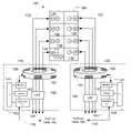
- FIG. 4shows an example embodiment of a communication interface 120 in which the coupler 148 is embodied as an inductive coupler 150 to provide common mode coupling of data signals to and from twisted pair conductors 122 .
- the coupler 148is embodied as an inductive coupler 150 to provide common mode coupling of data signals to and from twisted pair conductors 122 .
- components performing the same or similar functions as the corresponding components of the interface 120 of FIG. 3are given the same part numbers as their corresponding components.
- the inductive coupler 150 of interface 120takes advantage of the cross coupling effect of the twisted pair conductors 122 .
- the inductive couplermay be formed by a magnetically permeable toroid that surrounds the bundle of twisted pair conductors 122 that extend to the structural units 104 .
- the toroidmay be hinged to allow for easy installation and removal.
- a winding 151 around the toroidis connected to the modem 141 (e.g., via amplifiers and bandpass filters). Communications from the modem 141 of the downstream interface 140 traverse the winding 151 wound around the toroid 150 .
- the toroid 150inductively couples downstream data signals from the modem 141 onto the multiple sets of twisted pair conductors 122 . As a result, the downstream communication is transmitted along each one of multiple sets of twisted pair conductors.
- the bundlemay comprise more than one type of conductor.
- the bundlemay include one or more twisted pair conductors and one or more low voltage power lines and/or other conductor type.
- the data signals communicated by the interface 120may be in a different frequency band than voice band information (e.g., fax, voice communications) carried by the twisted pair conductors (which may be carried simultaneously).
- voice band informatione.g., fax, voice communications
- the data signals communicated by the interface 120also may be in a different frequency band than digital subscriber line (DSL) data carried by the twisted pair conductors (which may be carried simultaneously).
- DSLdigital subscriber line
- a low pass filter 152(to attenuate the data signals) also may be included to avoid or minimize egression of the data signals form the multi-unit structure along a twisted pair conductor network, such as the public switched telephone network, while allowing the voice band and/or DSL signals to pass.
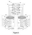
- FIG. 5shows an example multi-unit structure 102 topology in which multiple communication interfaces 120 are implemented to deliver communications to the structural units 104 .
- Multiple communication interfaces 120may be desirable, for example, in structures having excessive communication traffic, when the bundles are sufficiently large to preclude reliable coupling to all the conductors, and/or for other reasons. In such cases, coupling all the downstream communications onto every set of twisted pair conductors 122 may exceed a maximum bandwidth (e.g., the maximum data rate of the interface 120 ). By separating the sets of twisted pair conductors 122 into two or more bundles, and connecting each bundle to a separate interface 120 , greater communication traffic can be provided within the structure 102 .
- each bundlemay be allocated a separate coupler 148 / 150 , both of which may form part of the same downstream interface 140 of the same interface 120 , to allow for better coupling.
- one method of providing communicationsmay include providing a first communications interface to provide communications to the structure via a bundle, determining that the data traffic through the communications interface has reached a predetermined capacity, separating the bundle into two or more bundles, and providing communications over the two or more bundles via two or more communications interfaces.
- the bundled communication media 122 coupled to the communication interface 120may be multiple LV power lines (which may or may not be conductively connected).
- the coupler 150couples the signals to and from the LV power lines which extend to respective units 104 .
- the modems 132may be embodied by power line modems, such as of the type that plug into a power outlet.
- a user device 130may connect to the power line modem to communicate via the network 100 .
- the bundled communication media 122 coupled to the communication interface 120may be multiple shielded coaxial cables.
- the coaxial cablesextend to the respective structural units 104 .
- the coupler 150may couple the signals to and from the outer shielding of the coaxial cables.
- the modem 132may be embodied by a cable modem or any suitable modem with a MAC layer.
- a user device 130may connect to the cable modem or other modem to access the network 100 .
- only one coaxial cablemay extend to multiple units with the cable being split (via a T connector) for each floor and/or unit.
- the couplermay be used to couple data signals to and from the coaxial cable (e.g., the shield).
- the downstream communicationsmay be received by the modems of the communication devices 132 within each of multiple structural units 104 .
- the modemsthen process the received data packets (demodulate, decode, and decrypt), and determine whether the destination address (e.g., MAC address or IP address) of the packet matches or corresponds to the address of any local destination device—for example, depending on the architecture of the system, the MAC address of local modem of the communication device 132 or the IP address of a user device 130 . If the destination address within the received data packet communication does not correspond to a local destination address, then the communication is discarded. When the destination address within the received data packet communication does correspond to a local destination address, the communication is processed (e.g., provided to the destination device).
- the destination addresse.g., MAC address or IP address
- the router 142may inspect the IP source address or IP destination address and set priority tags of the upstream data packets (data packets transmitted from communication devices 132 ) accordingly. For example, if the source address of the upstream data packet corresponds to a Voice-over-IP (VoIP) endpoint, the router may set the IEEE 802.1 p priority to 6 and sets a DiffServ priority to EF. In a second embodiment, the DiffServ tag may already be set (e.g., by the end user device) and the router may inspect both the source and destination addresses. Accordingly, in some instances the communication interface 120 may receive multiple communications from multiple communication devices 132 , and prioritize processing and further transmission of one communication over another according to predefined criteria. In addition, in some embodiment it may be desirable to perform channel encoding/decoding, source encoding/decoding, error checking, and/or error correction at each device (e.g., 120 and 132 ).
- VoIPVoice-over-IP
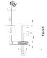
- FIG. 6illustrates an example embodiment of a communication device 132 for providing communications between a user device 130 and the communications interface 120 .
- this example embodimentincludes a common mode coupling mechanism 250 that is substantially similar to the coupler 150 described above.
- data signalsare coupled to and from the twisted pair conductor set 122 and the winding 240 via inductance.
- the twisted pair conductors 122 a and 122 btraverse through the aperture of the coupler 250 and are each connected to ground via an impedance 255 a and 255 b .
- Impedances 255may be high impedance impedances for low frequencies (e.g., voice and DSL frequencies) and lower impedance for the high frequencies of the data signals to be communicated (e.g., a capacitor or high pass filter).
- the two ends 240 of the winding 251 of the coupler 250are connected to the first port of the modem 220 . While both ends 240 of the winding 251 are shown to be connected to the modem 220 , in practice, one end of the winding, and one input to the modem 220 may both be connected to neutral (ground).
- the modem 220includes a media access layer MAC layer for layer two addressing.
- the modem 220may also, or alternately, support layer 3 addressing.
- the modem 220may comprises a HomePlug 1.0, A/V, or Turbo modem. While not shown, the winding 251 may be coupled to the modem 220 via one or more band pass filters and amplifiers to provide signal conditioning.
- the second port of the modem 220is connected to a user device 130 via user device interface that includes port 260 .
- the device 132also may include an RJ-11 connector 280 for connecting to a standard telephone wall socket for connecting to the twisted pair conductors 122 of the structure.
- the components of communication device 132may be housed in one or more housings and, also may be integrated into a wall unit behind a telephone/data face plate.
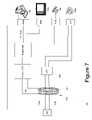
- FIG. 7illustrates another example embodiment of a communication device 132 for providing communications between one or more user devices 130 and the communications interface 120 .
- This example embodiment of the communication device 132includes multiple ports 260 a - c for connecting to a plurality of user devices 130 a - c .
- the modem 220may be connected to a routing device 281 (a router, switch, or bridge) that is connected to two, three, four, or more ports 260 and provide routing (including routing, switching, or bridging) of data to and from one or more user devices 130 .
- the routing device 281may include a routing table (e.g., stored in memory) that includes an address for each of the plurality of user devices 130 to which the device 132 is connected.
- Routing device 281also may be configured to prioritize transmission of upstream data based, for example, on the type data (e.g., give VoIP data a higher priority than computer data) or the type of device (e.g., give a VoIP telephone a higher priority than a computer).
- the twisted pair conductor set 122may traverse through the common mode coupler 250 , through a low pass filter 152 (as described above) and be connected to another port 270 (e.g., having an RJ-11 socket) that may be connected to an analog user device such as a conventional PSTN telephone or a DSL transceiver. This port 270 may likewise be present on the embodiment of FIG. 6 as well.
- ports 260 a - ccomprise digital ports and port 270 comprises an analog port.
- the device 132also may include an RJ-11 connector 280 for connecting to a standard telephone socket for connecting to the twisted pair conductors 122 of the structure.
- the components of communication device 132may be housed in one or more housings.
- port 260 amay be connected to a computer 130 a
- port 260 bmay be connected to a television 130 b for the reception of IP TV
- a port 260 cmay be connected to telephone 130 c for VoIP communications.
- Each of these devicesmay have an integrated, or separate, processing device to convert the received IP data to the appropriate format and protocol for use by the device 130 .
- the telephone 130 c connected to port 260 cmay include an analog telephone adapter (ATA) or an ATA may be connected to the port 260 c or integrated into the device 132 .
- port 270may be connected a telephone (as shown) for normal PSTN communications or may be connected to a DSL transceiver to provide DSL communications.
- the user devices 130 of some embodimentsmay be coupled to a communication device 132 that couples data to and from a twisted pair conductor set via a common mode non-conductive coupler (an inductive coupler in these embodiments).
- a common mode non-conductive coupleran inductive coupler in these embodiments.
- only one conductor of the twisted pair conductor sete.g., 122 a
- the routing device 281may be external to the communication device 132 .
- a capacitive coupler or a hybrid capacitive-inductive couplermay be employed to allow coupling. Like the inductive coupler described above, some embodiments of such couplers may allow communication of the data signals to and from the conductors without making electrical (conductive) contact and are examples of non-conductive couplers.
- the downstream interface 140may be conductively connected to one (or both) conductors of each set of the twisted pair conductors. In yet another embodiment, the downstream interface 140 may be conductively connected to one (or both) conductors of some subset of the entire bundle (in which case the signals may cross couple to and from the conductors to which the device 120 is not conductively coupled).
- the device 120may transmit the data packets with different encryption keys so that only the one or more communication devices that are the correct destination devices can decrypt and process the data packet.
- a different encryption keymay be used to communicate with each device 120 .
- the modem 141instead of a common mode coupler 150 , the modem 141 may be conductively coupled to some of the conductors 122 to differentially transmit data on one or more pairs of conductors 122 , wherein the one or more pairs may be some subset of the total set conductors 122 available.
- Data signalsmay then cross-couple from the pairs of conductors to which the modem 141 is conductively connected to be present, and be communicated over, the entire bundle of conductors 122 or some other subset of the conductors 122 (that may be greater in number than the conductors 122 to which the modem 122 is conductively connected).
- the modem 141may be connected to some of the conductors 12 (e.g., for differential transmission instead of common mode) and the data signals may cross couple to additional (e.g., the remaining) conductors 122 for reception by the desired communication device 132 and user device.
- an addressing layere.g., MAC layer
- NIDoutdoor network interface device
- VDSLVery High Speed Digital Subscriber Line
Landscapes
- Engineering & Computer Science (AREA)
- Computer Networks & Wireless Communication (AREA)
- Signal Processing (AREA)
- Power Engineering (AREA)
- Telephonic Communication Services (AREA)
- Cable Transmission Systems, Equalization Of Radio And Reduction Of Echo (AREA)
Abstract
Description
Claims (33)
Priority Applications (2)
| Application Number | Priority Date | Filing Date | Title |
|---|---|---|---|
| US11/693,980US7596079B2 (en) | 2006-05-31 | 2007-03-30 | System and method for communicating in a multi-unit structure |
| PCT/US2007/069872WO2007143452A2 (en) | 2006-05-31 | 2007-05-29 | System and method for communicating in a multi-unit structure |
Applications Claiming Priority (2)
| Application Number | Priority Date | Filing Date | Title |
|---|---|---|---|
| US11/421,278US7602695B2 (en) | 2006-05-31 | 2006-05-31 | System and method for communicating in a multi-unit structure |
| US11/693,980US7596079B2 (en) | 2006-05-31 | 2007-03-30 | System and method for communicating in a multi-unit structure |
Related Parent Applications (1)
| Application Number | Title | Priority Date | Filing Date |
|---|---|---|---|
| US11/421,278Continuation-In-PartUS7602695B2 (en) | 2006-05-31 | 2006-05-31 | System and method for communicating in a multi-unit structure |
Publications (2)
| Publication Number | Publication Date |
|---|---|
| US20070280246A1 US20070280246A1 (en) | 2007-12-06 |
| US7596079B2true US7596079B2 (en) | 2009-09-29 |
Family
ID=38802212
Family Applications (1)
| Application Number | Title | Priority Date | Filing Date |
|---|---|---|---|
| US11/693,980Expired - Fee RelatedUS7596079B2 (en) | 2006-05-31 | 2007-03-30 | System and method for communicating in a multi-unit structure |
Country Status (2)
| Country | Link |
|---|---|
| US (1) | US7596079B2 (en) |
| WO (1) | WO2007143452A2 (en) |
Cited By (1)
| Publication number | Priority date | Publication date | Assignee | Title |
|---|---|---|---|---|
| US20100284163A1 (en)* | 2009-01-13 | 2010-11-11 | Jetlun Corporation | Method and system for isolating local area networks over a co-axial wiring for energy management |
Families Citing this family (9)
| Publication number | Priority date | Publication date | Assignee | Title |
|---|---|---|---|---|
| NL2006494C2 (en)* | 2011-03-25 | 2012-09-26 | Astrea Intellectueel Eigendomsrecht B V | Isolator device for passing through a signal. |
| CN103597883B (en) | 2011-04-18 | 2017-12-26 | 马维尔国际贸易有限公司 | Reduce the power consumption in wireless communication system |
| US9137823B1 (en) | 2011-05-23 | 2015-09-15 | Marvell International Ltd. | Downlink and uplink staggering techniques with aid bitmap segmentation |
| US9204371B2 (en) | 2011-11-23 | 2015-12-01 | Marvell World Trade Ltd. | 802.11 restricted access windows |
| US9155027B1 (en) | 2011-11-23 | 2015-10-06 | Marvell International Ltd. | 802.11 enhanced distributed channel access |
| US9445349B1 (en) | 2012-04-18 | 2016-09-13 | Marvell International Ltd. | 802.11ah duty cycle based channel access priorities |
| US9735855B2 (en) | 2012-04-18 | 2017-08-15 | Marvell World Trade Ltd. | Method and apparatus for relaying communication between an access point and a station in a wireless network |
| WO2013184889A1 (en) | 2012-06-08 | 2013-12-12 | Marvell World Trade Ltd. | Method and apparatus for restricting channel access to a wireless station operating in accordance with a power saving scheme |
| US9148873B1 (en) | 2012-07-05 | 2015-09-29 | Marvell International Ltd. | Method and apparatus for providing different types of physical layer devices access to a wireless medium |
Citations (62)
| Publication number | Priority date | Publication date | Assignee | Title |
|---|---|---|---|---|
| US3369078A (en) | 1965-06-28 | 1968-02-13 | Charles R. Stradley | System for transmitting stereophonic signals over electric power lines |
| US3736379A (en)* | 1971-10-08 | 1973-05-29 | Western Electric Co | Inductive data coupler |
| US3810096A (en) | 1972-09-14 | 1974-05-07 | Integrated Syst Co | Method and system for transmitting data and indicating room status |
| US3964048A (en) | 1974-01-28 | 1976-06-15 | General Public Utilities Corporation | Communicating over power network within a building or other user location |
| US4057793A (en) | 1975-10-28 | 1977-11-08 | Johnson Raymond E | Current carrier communication system |
| US4060735A (en) | 1976-07-12 | 1977-11-29 | Johnson Controls, Inc. | Control system employing a programmable multiple channel controller for transmitting control signals over electrical power lines |
| US4239940A (en) | 1978-12-26 | 1980-12-16 | Bertrand Dorfman | Carrier current communications system |
| US5066939A (en) | 1989-10-04 | 1991-11-19 | Mansfield Jr Amos R | Method and means of operating a power line carrier communication system |
| US5257006A (en) | 1990-09-21 | 1993-10-26 | Echelon Corporation | Method and apparatus for power line communications |
| US5319634A (en) | 1991-10-07 | 1994-06-07 | Phoenix Corporation | Multiple access telephone extension systems and methods |
| US5929748A (en) | 1997-06-12 | 1999-07-27 | Microsoft Corporation | Automated home control using existing electrical lines as a communications medium |
| US6151480A (en) | 1997-06-27 | 2000-11-21 | Adc Telecommunications, Inc. | System and method for distributing RF signals over power lines within a substantially closed environment |
| US6160795A (en) | 1997-03-21 | 2000-12-12 | Siemens Aktiengesellschaft | Network communication |
| US20020011923A1 (en) | 2000-01-13 | 2002-01-31 | Thalia Products, Inc. | Appliance Communication And Control System And Appliance For Use In Same |
| US20020021716A1 (en) | 1999-02-22 | 2002-02-21 | Terk Neil D. | Video transmission system and method utilizing phone lines in multiple unit dwellings |
| US6373377B1 (en) | 2000-10-05 | 2002-04-16 | Conexant Systems, Inc. | Power supply with digital data coupling for power-line networking |
| US6417762B1 (en) | 2001-03-30 | 2002-07-09 | Comcircuits | Power line communication system using anti-resonance isolation and virtual earth ground signaling |
| US20020186699A1 (en) | 2001-06-08 | 2002-12-12 | Kwok Timothy Chung Hing | System and method for providing high-speed communications access over an electrical network |
| US6526581B1 (en) | 1999-08-03 | 2003-02-25 | Ucentric Holdings, Llc | Multi-service in-home network with an open interface |
| US20030050737A1 (en) | 2001-09-10 | 2003-03-13 | Robert Osann | Energy-smart home system |
| US20030052770A1 (en) | 1999-11-15 | 2003-03-20 | Mansfield Amos R. | Fire system implemented with power line communications |
| US20030062990A1 (en) | 2001-08-30 | 2003-04-03 | Schaeffer Donald Joseph | Powerline bridge apparatus |
| US20030071719A1 (en) | 2001-10-02 | 2003-04-17 | Crenshaw Ralph E. | Method and apparatus for attaching power line communications to customer premises |
| US20030100288A1 (en) | 2001-11-29 | 2003-05-29 | General Electric Company One Research Circle | Universal PLC radio frequency enhanced bridge |
| US20030103307A1 (en) | 2000-04-19 | 2003-06-05 | Kauls Dostert | Method and device for conditioning electric installations in buildings for the rapid transmission of data |
| US20030106067A1 (en) | 2001-11-30 | 2003-06-05 | Hoskins Steve J. | Integrated internet protocol (IP) gateway services in an RF cable network |
| US6587739B1 (en) | 2000-09-29 | 2003-07-01 | Sunbeam Products, Inc. | Appliance communication and control system and appliances for use in same |
| US6614093B2 (en)* | 2001-12-11 | 2003-09-02 | Lsi Logic Corporation | Integrated inductor in semiconductor manufacturing |
| US20040066283A1 (en) | 2002-01-08 | 2004-04-08 | Manis Constantine N. | Power line communications system combining high bitrate and low bitrate transmissions |
| US6771775B1 (en) | 1998-08-17 | 2004-08-03 | Ascom Powerline Communications Ag | Arrangement for communicating messages via a low-voltage electricity supply system and adapter |
| US6778817B1 (en) | 1998-12-01 | 2004-08-17 | Phonex Corporation | Method and system for combining wireless phone jack and RF wireless communications |
| US20040178888A1 (en) | 2003-03-14 | 2004-09-16 | Coaxmedia, Inc. | Bi-directional transfer of signals between a power line communication system and a coaxial distribution system |
| US20040196144A1 (en) | 2001-10-02 | 2004-10-07 | Telkonet, Inc. | Method and apparatus for attaching power line communications to customer premises |
| US20040227623A1 (en) | 2003-05-07 | 2004-11-18 | Telkonet, Inc. | Network topology and packet routing method using low voltage power wiring |
| US20040233928A1 (en) | 2003-05-07 | 2004-11-25 | Telkonet, Inc. | Network topology and packet routing method using low voltage power wiring |
| US6842459B1 (en) | 2000-04-19 | 2005-01-11 | Serconet Ltd. | Network combining wired and non-wired segments |
| US20050046550A1 (en) | 2001-10-02 | 2005-03-03 | Crenshaw Ralph E. | Method and apparatus for attaching power line communications to customer premises |
| US20050164666A1 (en) | 2002-10-02 | 2005-07-28 | Lang Jack A. | Communication methods and apparatus |
| US6950567B2 (en)* | 2001-02-14 | 2005-09-27 | Current Technologies, Llc | Method and apparatus for providing inductive coupling and decoupling of high-frequency, high-bandwidth data signals directly on and off of a high voltage power line |
| US6952159B1 (en) | 2000-05-30 | 2005-10-04 | Ascom Powerline Communications Ag | Coupling device |
| US6956464B2 (en) | 2003-05-14 | 2005-10-18 | Abocom Systems, Inc. | Power apparatus having built-in powerline networking adapter |
| US6961303B1 (en) | 2000-09-21 | 2005-11-01 | Serconet Ltd. | Telephone communication system and method over local area network wiring |
| US20050249245A1 (en) | 2004-05-06 | 2005-11-10 | Serconet Ltd. | System and method for carrying a wireless based signal over wiring |
| US20060017324A1 (en) | 2004-07-21 | 2006-01-26 | Advanced Powerline Technologies, Inc. | Communications network using installed electrical power lines |
| US20060034330A1 (en) | 2003-03-17 | 2006-02-16 | Ryuichi Iwamura | Bandwidth management of virtual networks on a shared network |
| US20060038660A1 (en) | 2004-08-20 | 2006-02-23 | Tohru Doumuki | System and method for authenticating/registering network device in power line communication (PLC) |
| US20060049693A1 (en) | 2004-09-08 | 2006-03-09 | Satius, Inc. | Apparatus and method for transmitting digital data over various communication media |
| US20060072695A1 (en) | 2004-10-04 | 2006-04-06 | Ryuichi Iwamura | System and method for synchronizing audio-visual devices on a power line communications (PLC) network |
| US20060073805A1 (en) | 2004-10-04 | 2006-04-06 | Markus Zumkeller | Dynamic FD coexistence method for PLC systems |
| US20060140260A1 (en) | 2003-03-03 | 2006-06-29 | Tdk Corporation | Power supply line communication modem and power supply line communication system |
| US20060165054A1 (en) | 2005-01-21 | 2006-07-27 | Ryuichi Iwamura | Power line network bridge |
| US20060251179A1 (en) | 2005-03-28 | 2006-11-09 | Akros Silicon, Inc. | Ethernet bridge |
| US20070025244A1 (en) | 2005-07-27 | 2007-02-01 | Ayyagari Deepak V | Coexistance of access provider and in-home networks |
| US20070036171A1 (en) | 2005-08-10 | 2007-02-15 | Magin Gregory A | Bridging coaxial cable networks |
| US20070039035A1 (en) | 2005-08-10 | 2007-02-15 | Magin Gregory A | Communicating over coaxial cable networks |
| US20070136766A1 (en) | 2005-12-09 | 2007-06-14 | Ryuichi Iwamura | Cross-phase adapter for powerline communications (PLC) network |
| US20070183447A1 (en) | 1998-07-28 | 2007-08-09 | Israeli Company Of Serconet Ltd. | Local area network of serial intelligent cells |
| US20070189182A1 (en) | 2006-02-14 | 2007-08-16 | Berkman William H | Method for establishing power line communication link |
| US7269403B1 (en) | 2004-06-03 | 2007-09-11 | Miao George J | Dual-mode wireless and wired power line communications |
| US20070220570A1 (en) | 2006-03-14 | 2007-09-20 | Dawson Thomas P | Powerline communication (PLC) modem employing an analog electromagnetic transducer |
| US20070280442A1 (en) | 2006-04-18 | 2007-12-06 | Zhang Youjuan | NETWORK-BASED VOICE OVER POWER LINES (VoPL) SYSTEM AND METHODS |
| US20080057866A1 (en) | 2006-08-24 | 2008-03-06 | Sony Deutschland Gmbh | Method for transmitting a signal on a power line network, transmitting unit, receiving unit and system |
Family Cites Families (7)
| Publication number | Priority date | Publication date | Assignee | Title |
|---|---|---|---|---|
| US5844596A (en)* | 1989-07-14 | 1998-12-01 | Inline Connection Corporation | Two-way RF communication at points of convergence of wire pairs from separate internal telephone networks |
| US6243446B1 (en)* | 1997-03-11 | 2001-06-05 | Inline Connections Corporation | Distributed splitter for data transmission over twisted wire pairs |
| US5364395A (en)* | 1993-05-14 | 1994-11-15 | West Jr Hugh S | Arthroscopic surgical instrument with cauterizing capability |
| US5614905A (en)* | 1994-01-25 | 1997-03-25 | Crane; Ronald C. | High speed serial digital data to analog signal converter |
| US5710403A (en)* | 1996-10-15 | 1998-01-20 | Jusionis; Vytautas John | Orbital weldhead with integral cooling |
| US20060193310A1 (en)* | 2005-02-25 | 2006-08-31 | Telkonet, Inc. | Local area network above telephony methods and devices |
| US7764943B2 (en)* | 2006-03-27 | 2010-07-27 | Current Technologies, Llc | Overhead and underground power line communication system and method using a bypass |
- 2007
- 2007-03-30USUS11/693,980patent/US7596079B2/ennot_activeExpired - Fee Related
- 2007-05-29WOPCT/US2007/069872patent/WO2007143452A2/enactiveApplication Filing
Patent Citations (66)
| Publication number | Priority date | Publication date | Assignee | Title |
|---|---|---|---|---|
| US3369078A (en) | 1965-06-28 | 1968-02-13 | Charles R. Stradley | System for transmitting stereophonic signals over electric power lines |
| US3736379A (en)* | 1971-10-08 | 1973-05-29 | Western Electric Co | Inductive data coupler |
| US3810096A (en) | 1972-09-14 | 1974-05-07 | Integrated Syst Co | Method and system for transmitting data and indicating room status |
| US3964048A (en) | 1974-01-28 | 1976-06-15 | General Public Utilities Corporation | Communicating over power network within a building or other user location |
| US4057793A (en) | 1975-10-28 | 1977-11-08 | Johnson Raymond E | Current carrier communication system |
| US4060735A (en) | 1976-07-12 | 1977-11-29 | Johnson Controls, Inc. | Control system employing a programmable multiple channel controller for transmitting control signals over electrical power lines |
| US4239940A (en) | 1978-12-26 | 1980-12-16 | Bertrand Dorfman | Carrier current communications system |
| US5066939A (en) | 1989-10-04 | 1991-11-19 | Mansfield Jr Amos R | Method and means of operating a power line carrier communication system |
| US5257006A (en) | 1990-09-21 | 1993-10-26 | Echelon Corporation | Method and apparatus for power line communications |
| US5319634A (en) | 1991-10-07 | 1994-06-07 | Phoenix Corporation | Multiple access telephone extension systems and methods |
| US6160795A (en) | 1997-03-21 | 2000-12-12 | Siemens Aktiengesellschaft | Network communication |
| US5929748A (en) | 1997-06-12 | 1999-07-27 | Microsoft Corporation | Automated home control using existing electrical lines as a communications medium |
| US6151480A (en) | 1997-06-27 | 2000-11-21 | Adc Telecommunications, Inc. | System and method for distributing RF signals over power lines within a substantially closed environment |
| US20070183447A1 (en) | 1998-07-28 | 2007-08-09 | Israeli Company Of Serconet Ltd. | Local area network of serial intelligent cells |
| US6771775B1 (en) | 1998-08-17 | 2004-08-03 | Ascom Powerline Communications Ag | Arrangement for communicating messages via a low-voltage electricity supply system and adapter |
| US6778817B1 (en) | 1998-12-01 | 2004-08-17 | Phonex Corporation | Method and system for combining wireless phone jack and RF wireless communications |
| US20020021716A1 (en) | 1999-02-22 | 2002-02-21 | Terk Neil D. | Video transmission system and method utilizing phone lines in multiple unit dwellings |
| US6526581B1 (en) | 1999-08-03 | 2003-02-25 | Ucentric Holdings, Llc | Multi-service in-home network with an open interface |
| US20050128057A1 (en) | 1999-11-15 | 2005-06-16 | Mansfield Amos R. | Preventing unintended communication among power line communication devices associated with different premises power distribution lines of an electric power distribution system |
| US20060132299A1 (en) | 1999-11-15 | 2006-06-22 | Ge Security, Inc. | Power line communication system with system member identification |
| US20030052770A1 (en) | 1999-11-15 | 2003-03-20 | Mansfield Amos R. | Fire system implemented with power line communications |
| US20020011923A1 (en) | 2000-01-13 | 2002-01-31 | Thalia Products, Inc. | Appliance Communication And Control System And Appliance For Use In Same |
| US6842459B1 (en) | 2000-04-19 | 2005-01-11 | Serconet Ltd. | Network combining wired and non-wired segments |
| US20030103307A1 (en) | 2000-04-19 | 2003-06-05 | Kauls Dostert | Method and device for conditioning electric installations in buildings for the rapid transmission of data |
| US6952159B1 (en) | 2000-05-30 | 2005-10-04 | Ascom Powerline Communications Ag | Coupling device |
| US6961303B1 (en) | 2000-09-21 | 2005-11-01 | Serconet Ltd. | Telephone communication system and method over local area network wiring |
| US6587739B1 (en) | 2000-09-29 | 2003-07-01 | Sunbeam Products, Inc. | Appliance communication and control system and appliances for use in same |
| US6373377B1 (en) | 2000-10-05 | 2002-04-16 | Conexant Systems, Inc. | Power supply with digital data coupling for power-line networking |
| US6950567B2 (en)* | 2001-02-14 | 2005-09-27 | Current Technologies, Llc | Method and apparatus for providing inductive coupling and decoupling of high-frequency, high-bandwidth data signals directly on and off of a high voltage power line |
| US6417762B1 (en) | 2001-03-30 | 2002-07-09 | Comcircuits | Power line communication system using anti-resonance isolation and virtual earth ground signaling |
| US20020186699A1 (en) | 2001-06-08 | 2002-12-12 | Kwok Timothy Chung Hing | System and method for providing high-speed communications access over an electrical network |
| US20030062990A1 (en) | 2001-08-30 | 2003-04-03 | Schaeffer Donald Joseph | Powerline bridge apparatus |
| US20030050737A1 (en) | 2001-09-10 | 2003-03-13 | Robert Osann | Energy-smart home system |
| US6975212B2 (en) | 2001-10-02 | 2005-12-13 | Telkonet Communications, Inc. | Method and apparatus for attaching power line communications to customer premises |
| US20040196144A1 (en) | 2001-10-02 | 2004-10-07 | Telkonet, Inc. | Method and apparatus for attaching power line communications to customer premises |
| US20030071719A1 (en) | 2001-10-02 | 2003-04-17 | Crenshaw Ralph E. | Method and apparatus for attaching power line communications to customer premises |
| US20050046550A1 (en) | 2001-10-02 | 2005-03-03 | Crenshaw Ralph E. | Method and apparatus for attaching power line communications to customer premises |
| US20030100288A1 (en) | 2001-11-29 | 2003-05-29 | General Electric Company One Research Circle | Universal PLC radio frequency enhanced bridge |
| US20030106067A1 (en) | 2001-11-30 | 2003-06-05 | Hoskins Steve J. | Integrated internet protocol (IP) gateway services in an RF cable network |
| US6614093B2 (en)* | 2001-12-11 | 2003-09-02 | Lsi Logic Corporation | Integrated inductor in semiconductor manufacturing |
| US20040066283A1 (en) | 2002-01-08 | 2004-04-08 | Manis Constantine N. | Power line communications system combining high bitrate and low bitrate transmissions |
| US20050164666A1 (en) | 2002-10-02 | 2005-07-28 | Lang Jack A. | Communication methods and apparatus |
| US20060140260A1 (en) | 2003-03-03 | 2006-06-29 | Tdk Corporation | Power supply line communication modem and power supply line communication system |
| US20040178888A1 (en) | 2003-03-14 | 2004-09-16 | Coaxmedia, Inc. | Bi-directional transfer of signals between a power line communication system and a coaxial distribution system |
| US20060034330A1 (en) | 2003-03-17 | 2006-02-16 | Ryuichi Iwamura | Bandwidth management of virtual networks on a shared network |
| US20040227623A1 (en) | 2003-05-07 | 2004-11-18 | Telkonet, Inc. | Network topology and packet routing method using low voltage power wiring |
| US20040233928A1 (en) | 2003-05-07 | 2004-11-25 | Telkonet, Inc. | Network topology and packet routing method using low voltage power wiring |
| US6956464B2 (en) | 2003-05-14 | 2005-10-18 | Abocom Systems, Inc. | Power apparatus having built-in powerline networking adapter |
| US20050249245A1 (en) | 2004-05-06 | 2005-11-10 | Serconet Ltd. | System and method for carrying a wireless based signal over wiring |
| US7269403B1 (en) | 2004-06-03 | 2007-09-11 | Miao George J | Dual-mode wireless and wired power line communications |
| US20060017324A1 (en) | 2004-07-21 | 2006-01-26 | Advanced Powerline Technologies, Inc. | Communications network using installed electrical power lines |
| US20060038660A1 (en) | 2004-08-20 | 2006-02-23 | Tohru Doumuki | System and method for authenticating/registering network device in power line communication (PLC) |
| US20060049693A1 (en) | 2004-09-08 | 2006-03-09 | Satius, Inc. | Apparatus and method for transmitting digital data over various communication media |
| US20060072695A1 (en) | 2004-10-04 | 2006-04-06 | Ryuichi Iwamura | System and method for synchronizing audio-visual devices on a power line communications (PLC) network |
| US20060073805A1 (en) | 2004-10-04 | 2006-04-06 | Markus Zumkeller | Dynamic FD coexistence method for PLC systems |
| US20060187023A1 (en) | 2005-01-21 | 2006-08-24 | Ryuichi Iwamura | PLC breaker bridge |
| US20060165054A1 (en) | 2005-01-21 | 2006-07-27 | Ryuichi Iwamura | Power line network bridge |
| US20060251179A1 (en) | 2005-03-28 | 2006-11-09 | Akros Silicon, Inc. | Ethernet bridge |
| US20070025244A1 (en) | 2005-07-27 | 2007-02-01 | Ayyagari Deepak V | Coexistance of access provider and in-home networks |
| US20070036171A1 (en) | 2005-08-10 | 2007-02-15 | Magin Gregory A | Bridging coaxial cable networks |
| US20070039035A1 (en) | 2005-08-10 | 2007-02-15 | Magin Gregory A | Communicating over coaxial cable networks |
| US20070136766A1 (en) | 2005-12-09 | 2007-06-14 | Ryuichi Iwamura | Cross-phase adapter for powerline communications (PLC) network |
| US20070189182A1 (en) | 2006-02-14 | 2007-08-16 | Berkman William H | Method for establishing power line communication link |
| US20070220570A1 (en) | 2006-03-14 | 2007-09-20 | Dawson Thomas P | Powerline communication (PLC) modem employing an analog electromagnetic transducer |
| US20070280442A1 (en) | 2006-04-18 | 2007-12-06 | Zhang Youjuan | NETWORK-BASED VOICE OVER POWER LINES (VoPL) SYSTEM AND METHODS |
| US20080057866A1 (en) | 2006-08-24 | 2008-03-06 | Sony Deutschland Gmbh | Method for transmitting a signal on a power line network, transmitting unit, receiving unit and system |
Non-Patent Citations (6)
| Title |
|---|
| "Centralized Commercial Building Applications with the Lonworks(R) PLT-21 Power Line Transceiver", Lonworks Engineering Bulletin, Echelon, (Apr. 1997),1-22. |
| "Demand Side Management with Lonworks(R) Power Line Transceivers", Lonworks Engineering Bulletin, (Dec. 1996),1-36. |
| "International Search Report",International Search Report Dated Aug. 12, 2008 Application No. PCT/US07/69872, (Aug. 12, 2008). |
| "Written Opinion",Written Opinion Dated Aug. 12, 2008 Application No. PCT/USo7/69872, (Aug. 12, 2008). |
| Hawkins, Bob "Sault Ste. Marie, Canada's First Working BPL Installation", La Revuw des Radioamateurs Canadiens,(Jul. & Aug. 2004),1-4. |
| Horiguchi, Akira "High Speed Power Line Communication Technology", Mitsubishi Electric Advance vol. 109, (Mar. 2005),1-27. |
Cited By (2)
| Publication number | Priority date | Publication date | Assignee | Title |
|---|---|---|---|---|
| US20100284163A1 (en)* | 2009-01-13 | 2010-11-11 | Jetlun Corporation | Method and system for isolating local area networks over a co-axial wiring for energy management |
| US8385083B2 (en)* | 2009-01-13 | 2013-02-26 | Jetlun Corporation | Method and system for isolating local area networks over a co-axial wiring for energy management |
Also Published As
| Publication number | Publication date |
|---|---|
| US20070280246A1 (en) | 2007-12-06 |
| WO2007143452A3 (en) | 2008-11-27 |
| WO2007143452A2 (en) | 2007-12-13 |
Similar Documents
| Publication | Publication Date | Title |
|---|---|---|
| US7596079B2 (en) | System and method for communicating in a multi-unit structure | |
| US7308103B2 (en) | Power line communication device and method of using the same | |
| US7796025B2 (en) | Power line communication device and method | |
| US20090085726A1 (en) | Power Line Communications Coupling Device and Method | |
| US7450001B2 (en) | Power line communications system and method | |
| US6192399B1 (en) | Twisted pair communication system | |
| US8908673B2 (en) | Local area network of serial intelligent cells | |
| US6941576B2 (en) | System and methods for home network communications | |
| US9106427B2 (en) | Local area network | |
| US7602695B2 (en) | System and method for communicating in a multi-unit structure | |
| US20070054622A1 (en) | Hybrid power line wireless communication system | |
| US20060193310A1 (en) | Local area network above telephony methods and devices | |
| JP2010104037A (en) | Telephone outlet and system for local area network over telephone line | |
| JP2006528876A (en) | Network topology and packet routing method using low voltage power distribution lines | |
| JP2002509668A (en) | Twisted pair communication system | |
| KR100756244B1 (en) | Power over Ethernet based LAN repeater and Power over Ethernet hybrid repeater | |
| Casey | Implementing Ethernet in the industrial environment | |
| CA2290001A1 (en) | Twisted pair communication system | |
| Chowdhury | The Ethernet | |
| Rayburn | Digital Audio Interfacing and Networking | |
| WO2006056977A2 (en) | A communications system and method | |
| HK1120955B (en) | Ethernet system, ethernet transceiver and method for ethernet communication | |
| HK1120955A1 (en) | Ethernet system, ethernet transceiver and method for ethernet communication |
Legal Events
| Date | Code | Title | Description |
|---|---|---|---|
| AS | Assignment | Owner name:CURRENT TECHNOLOGIES, LLC, MARYLAND Free format text:ASSIGNMENT OF ASSIGNORS INTEREST;ASSIGNOR:BERKMAN, WILLIAM H.;REEL/FRAME:019423/0620 Effective date:20070608 | |
| AS | Assignment | Owner name:CURRENT TECHNOLOGIES, LLC, MARYLAND Free format text:ASSIGNMENT OF ASSIGNORS INTEREST;ASSIGNOR:BITTNER, DENIS;REEL/FRAME:019442/0426 Effective date:20070618 | |
| AS | Assignment | Owner name:CURRENT TECHNOLOGIES, LLC, MARYLAND Free format text:ASSIGNMENT OF ASSIGNORS INTEREST;ASSIGNOR:BITTNER, MARKUS;REEL/FRAME:019499/0066 Effective date:20070628 | |
| AS | Assignment | Owner name:AP CURRENT HOLDINGS, LLC, PENNSYLVANIA Free format text:SECURITY AGREEMENT;ASSIGNOR:CURRENT TECHNOLOGIES, LLC;REEL/FRAME:020518/0001 Effective date:20080129 Owner name:AP CURRENT HOLDINGS, LLC,PENNSYLVANIA Free format text:SECURITY AGREEMENT;ASSIGNOR:CURRENT TECHNOLOGIES, LLC;REEL/FRAME:020518/0001 Effective date:20080129 | |
| AS | Assignment | Owner name:CURRENT TECHNOLOGIES, LLC, MARYLAND Free format text:RELEASE BY SECURED PARTY;ASSIGNOR:AP CURRENT HOLDINGS, LLC;REEL/FRAME:021096/0131 Effective date:20080516 Owner name:CURRENT TECHNOLOGIES, LLC,MARYLAND Free format text:RELEASE BY SECURED PARTY;ASSIGNOR:AP CURRENT HOLDINGS, LLC;REEL/FRAME:021096/0131 Effective date:20080516 | |
| REMI | Maintenance fee reminder mailed | ||
| LAPS | Lapse for failure to pay maintenance fees | ||
| STCH | Information on status: patent discontinuation | Free format text:PATENT EXPIRED DUE TO NONPAYMENT OF MAINTENANCE FEES UNDER 37 CFR 1.362 | |
| FP | Lapsed due to failure to pay maintenance fee | Effective date:20130929 |