US7595963B1 - Head gimbal assembly including a flexure with a first conductive trace disposed between a slider and a dielectric layer - Google Patents
Head gimbal assembly including a flexure with a first conductive trace disposed between a slider and a dielectric layerDownload PDFInfo
- Publication number
- US7595963B1 US7595963B1US11/449,261US44926106AUS7595963B1US 7595963 B1US7595963 B1US 7595963B1US 44926106 AUS44926106 AUS 44926106AUS 7595963 B1US7595963 B1US 7595963B1
- Authority
- US
- United States
- Prior art keywords
- flexure
- disposed
- hga
- conductive trace
- dielectric layer
- Prior art date
- Legal status (The legal status is an assumption and is not a legal conclusion. Google has not performed a legal analysis and makes no representation as to the accuracy of the status listed.)
- Active, expires
Links
- 239000002184metalSubstances0.000claimsdescription32
- 229910052751metalInorganic materials0.000claimsdescription32
- 239000004642PolyimideSubstances0.000claimsdescription2
- 229920001721polyimidePolymers0.000claimsdescription2
- 229910001220stainless steelInorganic materials0.000claimsdescription2
- 239000010935stainless steelSubstances0.000claimsdescription2
- 239000000725suspensionSubstances0.000description6
- 238000004891communicationMethods0.000description5
- 239000000853adhesiveSubstances0.000description4
- 230000001070adhesive effectEffects0.000description4
- 238000013459approachMethods0.000description4
- 150000001875compoundsChemical class0.000description4
- 239000004593EpoxySubstances0.000description3
- 239000000463materialSubstances0.000description2
- 238000000034methodMethods0.000description2
- 230000003287optical effectEffects0.000description2
- 230000036316preloadEffects0.000description2
- RYGMFSIKBFXOCR-UHFFFAOYSA-NCopperChemical compound[Cu]RYGMFSIKBFXOCR-UHFFFAOYSA-N0.000description1
- 230000000712assemblyEffects0.000description1
- 238000000429assemblyMethods0.000description1
- 229910052802copperInorganic materials0.000description1
- 239000010949copperSubstances0.000description1
- 238000000151depositionMethods0.000description1
- PCHJSUWPFVWCPO-UHFFFAOYSA-NgoldChemical compound[Au]PCHJSUWPFVWCPO-UHFFFAOYSA-N0.000description1
- 239000010931goldSubstances0.000description1
- 229910052737goldInorganic materials0.000description1
- 230000001939inductive effectEffects0.000description1
- 238000000926separation methodMethods0.000description1
Images


Classifications
- G—PHYSICS
- G11—INFORMATION STORAGE
- G11B—INFORMATION STORAGE BASED ON RELATIVE MOVEMENT BETWEEN RECORD CARRIER AND TRANSDUCER
- G11B5/00—Recording by magnetisation or demagnetisation of a record carrier; Reproducing by magnetic means; Record carriers therefor
- G11B5/48—Disposition or mounting of heads or head supports relative to record carriers ; arrangements of heads, e.g. for scanning the record carrier to increase the relative speed
- G11B5/4806—Disposition or mounting of heads or head supports relative to record carriers ; arrangements of heads, e.g. for scanning the record carrier to increase the relative speed specially adapted for disk drive assemblies, e.g. assembly prior to operation, hard or flexible disk drives
- G11B5/486—Disposition or mounting of heads or head supports relative to record carriers ; arrangements of heads, e.g. for scanning the record carrier to increase the relative speed specially adapted for disk drive assemblies, e.g. assembly prior to operation, hard or flexible disk drives with provision for mounting or arranging electrical conducting means or circuits on or along the arm assembly
- G—PHYSICS
- G11—INFORMATION STORAGE
- G11B—INFORMATION STORAGE BASED ON RELATIVE MOVEMENT BETWEEN RECORD CARRIER AND TRANSDUCER
- G11B5/00—Recording by magnetisation or demagnetisation of a record carrier; Reproducing by magnetic means; Record carriers therefor
- G11B5/48—Disposition or mounting of heads or head supports relative to record carriers ; arrangements of heads, e.g. for scanning the record carrier to increase the relative speed
- G11B5/4806—Disposition or mounting of heads or head supports relative to record carriers ; arrangements of heads, e.g. for scanning the record carrier to increase the relative speed specially adapted for disk drive assemblies, e.g. assembly prior to operation, hard or flexible disk drives
- G11B5/4853—Constructional details of the electrical connection between head and arm
Definitions
- the present inventionrelates generally to disk drives, and in particular a head gimbal assembly including a flexure with a first conductive trace disposed between a slider and a dielectric layer.
- the typical hard disk driveincludes a head disk assembly (HDA) and a printed circuit board assembly (PCBA) attached to a disk drive base of the HDA.
- the HDAincludes at least one disk, a spindle motor for rotating the disk, and a head stack assembly (HSA).
- the PCBAincludes a disk controller for generating servo control signals.
- the HSAincludes a head for reading and writing data from and to the disk.
- the HSAis controllably positioned in response to the generated servo control signals from the disk controller to move the head relative to tracks of the disk.
- the HSAincludes an actuator assembly, at least one head gimbal assembly (HGA), and a flex cable assembly.
- the actuator assemblytypically includes an actuator having an actuator body with one or more actuator arms extending from the actuator body. Each actuator arm supports the HGA that includes a head.
- An actuator coilis supported by the actuator body. The actuator coil interacts with a magnet to form a voice coil motor.
- the PCBAcontrols current passing through the actuator coil that results in a torque being applied to the actuator.
- the HSAfurther includes the flex cable assembly in electrical communication with the PCBA.
- the flex cable assemblysupplies current to the coil and carries signals between the head and the PCBA.
- a flexureextends along the load beam and is considered a sub-component of the HGA.
- the headis attached and electrically connected to the flexure.
- the flexureincludes a flexure tail portion that extends away from the head.
- the flexure tail portionis disposed adjacent the actuator body and attaches with the flex cable assembly.
- the flexureincludes conductive traces that extend from adjacent the head and terminate at electrical connection points at the flexure tail portion.
- the flex cable assemblyincludes a flex cable with electrical conduits that correspond to the electrical connection points of the flexure.
- the headincludes a slider and a transducer disposed on the slider.
- Several conductive padsare distributed along a trailing side of the slider.
- the conductive padsare electrically connected to electrical components of the transducer that are disposed on a trailing surface of the slider. Such electrical components may include poles of a writer, shields of a read element, and electrical ground, for examples.
- the electrical padsare electrically bonded with the conductive traces of the flexure. Standard assignment or ordering of the conductive pads is common.
- the state of the art flexure designincludes not only a gimbal structure that provides compliance necessary for flying the slider, but also includes many conductive traces extending to the flexure tail portion for electrical connection with a preamplifier chip or “pre-amp.”
- the headincludes some electrical connection to ground. Different approaches have been taken to provide such grounding.
- the headis electrically grounded to the flexure, for example, using a conductive epoxy in contact with both the slider body and the flexure, or through a conductive via leading from a transducer terminal to the metal backing layer of the flexure.
- the headis grounded through a conductive trace leading to a pre-amp.
- This approach to groundingentails additional complexity and constraints because the pre-amp may be disposed at the flex cable to flexure tail interface at the actuator body, and so the grounding path is constrained by the routing patterns of other needed conductive traces on the flexure. Because the conductive traces are typically disposed in a common plane and cannot cross one another without electrically shorting, there are inherent limitations as to the trace routing patterns.
- a standard conductive trace routing configurationincludes the conductive traces that are to be connected to the innermost pair of the conductive pads being assigned to the outermost traces that extend along the flexure to the pre-amp.
- ordering of the electrical traces at the conductive padsconstrains the ordering of such traces at the pre-amp.
- a head gimbal assemblyfor a disk drive.
- the HGAincludes a slider, a load beam, a flexure and a base plate.
- the sliderincludes a top surface and an air bearing surface that opposes the top surface, a leading side, and a trailing side that opposes the leading side.
- the sliderfurther includes first, second and third electrically conductive pads disposed upon the trailing side. The first electrically conductive pad is disposed between the second and third electrically conductive pads.
- the flexureincludes a flexure body portion affixed to the load beam, a tongue portion with the slider being attached to the tongue portion, first and second gimbal arms extending between the flexure body and the tongue portion, a metal backing layer and a dielectric layer.
- the flexurefurther includes first, second, and third patterned conductive traces respectively electrically connected to the first, second, and third electrically conductive pads and disposed upon the dielectric layer.
- the first patterned conductive traceis disposed upon the dielectric layer between the top surface of the slider and the dielectric layer.
- the second patterned conductive traceis disposed in the tongue portion and extends along the first gimbal arm to the flexure body.
- the third patterned conductive traceis disposed in the tongue portion and extends along the second gimbal arm to the flexure body.
- the first patterned conductive traceis disposed between the second and third patterned conductive traces along the flexure body.
- the base plate, for mounting the HGA,is attached to the load beam.
- FIG. 1is an exploded top perspective view of a disk drive including a head gimbal assembly according to an embodiment of the present invention
- FIG. 2is an enlarged top perspective view of a head stack assembly of FIG. 1 that includes the head gimbal assembly according to an embodiment
- FIG. 3is an enlarged bottom perspective view of the head stack assembly of FIG. 1 ;
- FIG. 4is an exploded enlarged perspective view of a portion of the head gimbal assembly of FIG. 3 ;
- FIG. 5is the portion of the head gimbal assembly of FIG. 4 as assembled
- FIG. 6is an enlarged top plan view of a portion of the head gimbal assembly with a portion of a flexure shown;
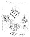
- FIG. 7is a further enlarged perspective view of a portion of the head gimbal assembly of the head stack assembly of FIG. 3 ;
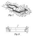
- FIG. 8is a cross-sectional side view of a portion of the flexure as seen along axis 8 - 8 of FIG. 6 .
- the disk drive 10includes a head disk assembly (HDA) 12 and a printed circuit board assembly (PCBA) 14 .
- the head disk assembly 12includes a disk drive housing having disk drive housing members, such as a disk drive base 16 and a cover 18 .
- the disk drive base 16 and the cover 18collectively house a disk 20 .
- a single disk 20 or additional disksmay be utilized.
- the disk 20includes an inner diameter (ID) 22 and an outer diameter (OD) 24 .
- the disk 20further includes a plurality of tracks for storing data.
- the disk 20may be of a magnetic recording type of storage device, however, other arrangements such as optical recording may be utilized.
- the head disk assembly 12further includes a spindle motor 26 for rotating the disk 20 about a disk rotation axis 28 .
- the head disk assembly 12further includes a head stack assembly (HSA) 30 rotatably attached to the disk drive base 16 in operable communication with the disk 20 .
- the head stack assembly 30includes an actuator 32 .
- the actuator 32includes an actuator body 34 and an actuator arm 36 that extends from the actuator body 34 .
- a suspension assembly 38Distally attached to the actuator arm 36 is a suspension assembly 38 .
- the suspension assembly 38supports a head 40 .
- the suspension assembly 38 with the head 40is referred to as a head gimbal assembly (HGA) 42 . It is contemplated that the number of actuator arms and suspension assemblies may vary depending upon the number of disks and disk surfaces utilized.
- the head 40typically includes a transducer for writing and reading data.
- the head 40may be referred to as a read head.
- Each transducertypically includes a writer and a read element.
- the transducer's writermay be of a longitudinal or perpendicular design, and the read element of the transducer may be inductive or magnetoresistive.
- the head 40may also include an objective lens and an active or passive mechanism for controlling the separation of the objective lens from a disk surface of the disk 20 .
- the disk 20includes opposing disk surfaces.
- the disk surfacetypically includes one or more magnetic layers. Data may be recorded along data annular regions on a single disk surface or both.
- the head stack assembly 30may be pivoted such that the head 40 is disposed adjacent to the various data annular regions from adjacent to the outer diameter 24 to the inner diameter 22 of the disk 20 .
- the actuator body 34includes a bore
- the actuator 32further includes a pivot bearing cartridge 44 engaged within the bore for facilitating the actuator body 34 to rotate between limited positions about an axis of rotation 46 .
- the actuator 32further includes a coil support element 48 that extends from one side of the actuator body 34 opposite the actuator arms 36 .
- the coil support element 48is configured to support a coil 50 .
- First and second magnets 52 , 54are supported by first and second magnet supports 56 , 58 which are attached to the disk drive base 16 (the first magnet 52 is denoted in dashed lining and it is understood that it is disposed at an underside of the first magnet support 56 ).
- the coil 50interacts with the first and second magnets 52 , 54 to form a voice coil motor for controllably rotating the actuator 32 .
- the printed circuit board assembly 14includes a servo control system in the form of a disk controller for generating servo control signals.
- the head stack assembly 30further includes a flex cable assembly 60 .
- the flex cable assembly 60includes a flex cable 62 and a cable connector 64 .
- the cable connector 64is attached to the disk drive base 16 and is disposed in electrical communication with the printed circuit board assembly 14 .
- the flex cable assembly 60supplies current to the coil 46 and carries signals between the head 40 and the printed circuit board assembly 14 .
- FIG. 3is an enlarged bottom perspective view of the head stack assembly 30 of FIG. 1 .
- the suspension assembly 38includes a load beam 66 .
- the load beam 66is coupled to the actuator arm 36 with the load beam 66 extending distally from the actuator arm 36 .
- the load beam 66includes a bend area that makes the load beam 66 compliant in a direction normal to the disk 20 to allow an air bearing to position the head 40 at a desired fly height above a surface of the disk 20 .
- the bend area of the load beam 66is initially plastically deformed through a macroscopic angle so that when it is elastically straightened during disk drive assembly it can provide a pre-load force upon the head 40 against the disk 20 .
- the pre-load forceis commonly referred to as a “gram load” because it is typically measured in grams.
- a flexure 68is electrically connected to the flex cable 62 . As shown in FIG. 3 , the flexure 68 is overlaid on the actuator arm 36 and the distally extending load beam 66 .
- the flexure 68may be referred to as a trace assembly or a trace suspension assembly.
- the flexure 68extends along the actuator arm 36 and the load beam 66 .
- the head 40is attached to and electrically connected to the flexure 68 .
- the flexure 68includes a flexure tail portion 70 that is opposite the attachment end of the head 40 .
- the flexure tail portion 70is disposed adjacent the actuator body 34 .
- FIG. 4there is depicted an exploded enlarged perspective view of a portion of the head gimbal assembly 42 of FIG. 3 .
- FIG. 5is the portion of the head gimbal assembly 42 of FIG. 4 as assembled.
- FIG. 6is an enlarged top plan view of a portion of the head gimbal assembly 42 with a portion of the flexure 68 shown but without a slider 96 .
- FIG. 7is a further enlarged perspective view of a portion of the head gimbal assembly 42 of the head stack assembly 30 of FIG. 3 .
- the head gimbal assembly 42further includes a metal base plate 72 .
- the metal base plate 72may be used to swage attach the load beam 66 to an end of the actuator arm 36 .
- the metal base plate 72may be disposed between the load beam 66 and the actuator arm 36 .
- the flexure 68is disposed upon the load beam 66 .
- the head gimbal assembly 42for the disk drive 10 .
- the head gimbal assembly 42includes the read head 40 , the metal load beam 66 , the flexure 68 , and the metal base plate 72 .
- the read head 40includes the slider 96 and a transducer.
- the slider 96includes a top surface 74 and an air bearing surface 76 that opposes the top surface 74 , a leading side 80 , and a trailing side 78 that includes the transducer and opposes the leading side 80 .
- the slider 96further includes first, second and third electrically conductive pads 82 a - c disposed upon the trailing side 78 .
- the first electrically conductive pad 82 ais disposed between the second and third electrically conductive pads 82 b - c .
- the flexure 68includes a flexure body portion 84 , a tongue portion 86 with the slider 96 affixed to the load beam 66 , first and second gimbal arms 88 , 90 extending between the flexure body portion 84 and the tongue portion 86 , a metal backing layer 98 , and a dielectric layer 92 .
- the flexure 68further includes first, second, and third patterned conductive traces 94 a - c respectively electrically connected to the first, second, and third electrically conductive pads 82 a - c and disposed upon the dielectric layer 92 .
- the first patterned conductive trace 94 ais disposed upon the dielectric layer 92 between the top surface 74 of the slider 96 and the dielectric layer 92 .
- the second patterned conductive trace 94 bis disposed in the tongue portion 86 and extends along the first gimbal arm 88 to the flexure body portion 84 .
- the third patterned conductive trace 94 cis disposed in the tongue portion 86 and extends along the second gimbal arm 90 to the flexure body portion 84 .
- the first patterned conductive trace 94 ais disposed between the second and third patterned conductive traces 94 b - c along the flexure body portion 84 .
- the base plate 72is attached to the load beam 66 .
- the flex cable 62may be electrically connected to the flexure 68 at the flexure body portion 84 .
- the flexure body portion 84includes the flexure tail 70 and the flex cable 62 may be electrically connected to the flexure tail 70 .
- the flex cable 62 and the flexure tail 70are electrically and mechanically connected to each other according to any of those methods that are well known to one of ordinary skill in the art.
- a pre-ampmay additionally be provided adjacent the flexure tail 70 at the interface with the flex cable 62 .
- first, second, and third patterned conductive traces 94 a - care contemplated to impact the pin-out ordering at the connection location with the flex cable 62 .
- the first patterned conductive trace 94 a(the trace that includes a portion between the top surface 74 of the slider 96 and the dielectric layer 92 ) may be routed to any other ordered location along the flexure body portion 84 that is between two other traces according to various other embodiments not shown.
- an inner electrically conductive padmay be connected to an inner trace routing location in the flexure body portion 84 relative to two other pad/trace combinations.
- the tongue portion 80 and the first and second gimbal arms 82 , 84may be generally referred to as a gimbal.
- the first and second gimbal arms 82 , 84provide angular compliance to the head 40 to allow the head 40 to follow undulations of the surface of the rotating disk 20 .
- the flexure 68includes the metal backing layer 98 .
- the metal backing layer 98is included within the tongue portion 86 and the first and second gimbal arms 88 , 90 .
- the dielectric layer 92may be disposed between the metal backing layer 98 and the conductive traces 94 such as shown.
- the metal backing layer 98may be stainless steel, for example.
- the metal backing layer 98may be used to provide structural support for the conductive traces 94 and the slider 96 .
- the metal backing layer 98may be affixed to the load beam 66 in the flexure body portion 84 .
- the metal backing layer 98may be spot-welded to the load beam 66 .
- the metal backing layer 98may be attached to an electrical ground.
- the metal backing layer 98may be in electrical communication with other components of the head gimbal assembly 42 , such as the load beam 66 or the metal base plate 72 .
- the load beam 66is joined with the metal base plate 72 which is attached to the actuator arm 36 .
- the actuator arm 36may be disposed in electrical communication with the disk drive base 16 via the pivot bearing cartridge 44 , and thus is considered to be an electrical ground.
- the load beam 66may include a dimple 122 as seen in FIG. 4 .
- the tongue portion 86may contact the dimple portion 122 for structural support as well as electrical grounding of the metal backing layer 98 .
- the dielectric layer 92may be formed of various materials, such as polyimide.
- the dielectric layer 92may be formed of discrete portions such as shown.
- the dielectric layer 92may serve to electrically insulate the conductive traces 94 from electrically shorting with the metal backing layer 98 .
- the slider 96may further include fourth, fifth, and sixth electrically conductive pads 82 d - f disposed upon the trailing side 78 .
- the first and third electrically conductive pads 82 a,care innermost ones of the pads 82 .
- the fourth and sixth electrically conductive pads 82 d,fare outermost ones of the pads 82 .
- the flexure 68may further include corresponding fourth, fifth, and sixth patterned conductive traces 94 d - f disposed upon the dielectric layer 92 .
- the fourth patterned conductive trace 94 dis disposed in the tongue portion 86 and extends along the first gimbal arm 88 to the flexure body portion 84 .
- the fifth patterned conductive trace 94 eis disposed in the tongue portion 86 and extends along the second gimbal arm 90 to the flexure body portion 84 .
- the first patterned conductive trace 94 ais disposed along the flexure body portion 84 between the fourth and fifth patterned conductive traces 94 d - e .
- the sixth patterned conductive trace 94 fis disposed in the tongue portion 86 and extends along the second gimbal arm 90 to the flexure body 84 .
- the first and sixth patterned conductive traces 94 a,fare innermost ones of the traces 94 .
- the second and third patterned conductive traces 94 b,care outermost ones of the conductive traces 94 .
- the patterned conductive traces 94 a - fmay respectively terminate at connection terminals 100 a - f disposed at the tongue portion 86 .
- the electrically conductive pads 82 a - fmay be electrically connected to the patterned conductive traces 94 a - f according to any of those methods that are well known to one of ordinary skill in the art.
- gold ball bonds 102may be used to electrically connect the electrically conductive pads 82 a - f to the patterned conductive traces 94 a - f.
- the patterned conductive traces 94 a - fVarious deposition techniques may be utilized to form the conductive traces 94 a - f upon the dielectric layer 92 . It is understood that the conductive traces 94 would not include discrete insulated wiring for example.
- the conductive traces 94may be formed of a metal, such as copper.
- the first patterned conductive trace 94 ais disposed upon the dielectric layer 92 between the top surface 74 of the slider 96 and the dielectric layer 92 .
- the first patterned conductive trace 94 amay include a trace segment 104 .
- the slider 96is not shown in FIG. 6 .
- a slider periphery 106is shown to indicate the installed location of the slider 96 .
- the first patterned conductive trace 94 ais positioned to be an innermost one of the conductive traces 94 along the flexure body portion 84 because the trace segment 104 is routed “underneath” the slider 96 from the connection terminal 100 a . This is in contrast to the other ones of the conductive traces 94 b - f that extend from the connection terminals 110 b - f in a conventional manner which is initially away from the trailing side 78 of the slider 96 .
- the first patterned conductive trace 94 amay include a support portion 108 .
- the support portion 108is disposed between the top surface 74 of the slider 96 and the dielectric layer 92 within the slider periphery 106 . As such, the support portion 108 supports the slider 96 .
- the support portion 108may be generally rectangular shaped such as shown or may be of other geometries.
- An adhesive compoundsuch as a structural epoxy, may be used for secure attachment of the slider 96 to the tongue portion 86 . Though not shown, such adhesive compound may be distributed across the dielectric layer 92 within the geometry defined by the support portion 108 .
- the support portion 108may further include an additional support segment 114 to facilitate further structural support of the slider 96 and a balanced distribution of adhesive compound.
- the tongue portion 86may include exposed features 110 , 112 through the dielectric layer 92 . Such exposed features 110 , 112 may accommodate additional adhesive compounds for secure attachment of the slider 96 . Moreover, a conductive epoxy may be used to electrically ground the top surface 74 to the tongue portion 86 .
- the first patterned conductive trace 94 amay be connected to an electrical ground. In the embodiment shown, the first patterned conductive trace 94 a is electrically connected to the metal backing layer 98 through the dielectric layer 92 . As shown in FIGS. 4 and 6 , the dielectric layer 92 may include a via 120 . FIG. 7 is a cross-sectional side view of a portion of the flexure 68 as seen along axis 8 - 8 of FIG. 6 . A through hole 116 may be formed through the dielectric layer 92 and the metal backing layer 98 . The first patterned conductive trace 94 a may include a connecting segment 118 that extends between the connection terminal 100 a and the through hole 116 .
- the via 120may be formed of the same material of the conductive trace 94 a .
- the first patterned conductive trace 94 amay be electrically connected to the metal backing layer 98 through the via 120 .
- the via 120may be used to provide an electrical ground to the electrically conductive pad 82 a through the ball bond 102 a and the connecting segment 118 .
- a common groundmay be established from the conductive pad 82 a to the first patterned conductive trace 94 a at an innermost pin-out location of the flexure tail portion 70 at the interface with the flex cable 62 .
Landscapes
- Supporting Of Heads In Record-Carrier Devices (AREA)
Abstract
Description
Claims (14)
Priority Applications (1)
| Application Number | Priority Date | Filing Date | Title |
|---|---|---|---|
| US11/449,261US7595963B1 (en) | 2006-06-07 | 2006-06-07 | Head gimbal assembly including a flexure with a first conductive trace disposed between a slider and a dielectric layer |
Applications Claiming Priority (1)
| Application Number | Priority Date | Filing Date | Title |
|---|---|---|---|
| US11/449,261US7595963B1 (en) | 2006-06-07 | 2006-06-07 | Head gimbal assembly including a flexure with a first conductive trace disposed between a slider and a dielectric layer |
Publications (1)
| Publication Number | Publication Date |
|---|---|
| US7595963B1true US7595963B1 (en) | 2009-09-29 |
Family
ID=41109841
Family Applications (1)
| Application Number | Title | Priority Date | Filing Date |
|---|---|---|---|
| US11/449,261Active2027-12-12US7595963B1 (en) | 2006-06-07 | 2006-06-07 | Head gimbal assembly including a flexure with a first conductive trace disposed between a slider and a dielectric layer |
Country Status (1)
| Country | Link |
|---|---|
| US (1) | US7595963B1 (en) |
Cited By (45)
| Publication number | Priority date | Publication date | Assignee | Title |
|---|---|---|---|---|
| US20080130175A1 (en)* | 2006-12-05 | 2008-06-05 | Samsung Electronics Co., Ltd | Head gimbal assembly of hard disk drive |
| US20100134925A1 (en)* | 2008-12-03 | 2010-06-03 | Eun Kyu Jang | Apparatus minimizing impedance in flex-to-printed circuit board connection through the disk base of a hard disk drive |
| US20100220414A1 (en)* | 2009-03-02 | 2010-09-02 | Seagate Technology Llc | Head gimbal assembly without bus traces for plating |
| US20110090601A1 (en)* | 2009-10-16 | 2011-04-21 | Sae Magnetics (H.K.) Ltd. | Suspension with flexure tail and manufacturing method thereof, head stack assembly and disk drive unit with the same |
| US20120170150A1 (en)* | 2011-01-05 | 2012-07-05 | Sae Magnetics (H.K.) Ltd. | Suspension with supporting pieces, head gimbal assembly and disk drive unit with the same |
| US8488279B1 (en)* | 2011-11-22 | 2013-07-16 | Western Digital (Fremont), Llc | Disk drive suspension assembly with flexure having stacked interleaved traces |
| US8879212B1 (en) | 2013-08-23 | 2014-11-04 | Western Digital Technologies, Inc. | Disk drive suspension assembly with flexure having dual conductive layers with staggered traces |
| US8929180B1 (en) | 2013-04-25 | 2015-01-06 | Western Digital Technologies, Inc. | Energy-assisted magnetic recording device having laser driving signal and magnetic write signal sharing same electrical conductor |
| US8934199B1 (en) | 2014-03-31 | 2015-01-13 | Western Digital Technologies, Inc. | Disk drive head suspension tail with bond pad edge alignment features |
| US8976491B1 (en) | 2013-05-09 | 2015-03-10 | Western Digital Technologies, Inc. | Disk drive head suspension distal non-op shock limiter with branched arms |
| US8988830B1 (en) | 2013-05-13 | 2015-03-24 | Western Digital (Fremont), Llc | Air bearing design to mitigate lube waterfall effect |
| US20150109704A1 (en)* | 2010-12-28 | 2015-04-23 | Dai Nippon Printing Co., Ltd. | Suspension substrate, suspension, head suspension, hard disk drive, and method for manufacturing suspension substrate |
| US9042048B1 (en) | 2014-09-30 | 2015-05-26 | Western Digital (Fremont), Llc | Laser-ignited reactive HAMR bonding |
| US9064513B1 (en) | 2014-03-07 | 2015-06-23 | Western Digital Technologies, Inc. | Disk drive suspension assembly with flexure having dual conductive layers with staggered traces |
| US9070387B1 (en) | 2013-08-23 | 2015-06-30 | Western Digital Technologies, Inc. | Integrated heat-assisted magnetic recording head/laser assembly |
| US9093102B1 (en) | 2013-03-12 | 2015-07-28 | Western Digital Technologies, Inc. | Systems and methods for tuning seed layer hardness in components of magnetic recording systems |
| US9099145B1 (en) | 2013-12-24 | 2015-08-04 | Western Digital (Fremont), Llc | High contrast alignment marker |
| US9105282B1 (en) | 2013-05-20 | 2015-08-11 | Western Digital Technologies, Inc. | Head gimbal assembly carrier with adjustable protective bar |
| US9135935B1 (en) | 2013-10-11 | 2015-09-15 | Western Digital Technologies, Inc. | Customized head gimbal assembly bonding skew angle for adjusting two-dimensional magnetic recording reader alignment |
| US9165579B1 (en) | 2014-09-26 | 2015-10-20 | Western Digital (Fremont), Llc | Air bearing area configuration for reducing flying height hump across a stroke |
| US9171562B1 (en) | 2015-03-19 | 2015-10-27 | Western Digital (Fremont), Llc | Patterned metal layer to control solder connection between laser and submount in a magnetic head |
| US9183859B1 (en) | 2014-11-11 | 2015-11-10 | Western Digital (Fremont), Llc | HAMR writer pole length characterization |
| US9190089B1 (en) | 2014-12-24 | 2015-11-17 | Western Digital (Fremont), Llc | Air bearing area configuration for contaminating particle removal |
| US9190090B1 (en) | 2014-12-24 | 2015-11-17 | Western Digital (Fremont), Llc | Multi step lube blocking air bearing area configuration |
| US9202478B1 (en) | 2015-02-10 | 2015-12-01 | Western Digital (Fremont), Llc | Method and structure for soldering a laser submount to a mounting face of a slider |
| US9230580B1 (en) | 2010-06-30 | 2016-01-05 | Western Digital Technologies, Inc. | Suspension assembly having a microactuator grounded to a flexure |
| US9242340B1 (en) | 2013-03-12 | 2016-01-26 | Western Digital Technologies, Inc. | Method to stress relieve a magnetic recording head transducer utilizing ultrasonic cavitation |
| US9257138B1 (en) | 2014-10-28 | 2016-02-09 | Western Digital (Fremont), Llc | Slider assembly and method of manufacturing same |
| US9293157B1 (en) | 2012-06-28 | 2016-03-22 | Western Digital Technologies, Inc. | Automated active feedback slice and view milling of magnetic head cross-sections |
| US9315008B1 (en) | 2013-07-16 | 2016-04-19 | Western Digital Technologies, Inc. | Method and apparatus for aligning an illumination unit to a slider for a magnetic recording device |
| US9343084B2 (en) | 2012-03-14 | 2016-05-17 | Western Digital Technologies, Inc. | Systems and methods for correcting slider parallelism error using compensation lapping |
| US9361916B1 (en) | 2014-03-13 | 2016-06-07 | Western Digital (Fremont) | Electrical lapping guide for dimensional control of back side of heat assisted magnetic recording device |
| US9368139B1 (en) | 2015-03-20 | 2016-06-14 | Western Digital (Fremont), Llc | Slider back side etching to increase shear strength between suspension and slider |
| US9372078B1 (en) | 2014-06-20 | 2016-06-21 | Western Digital (Fremont), Llc | Detecting thickness variation and quantitative depth utilizing scanning electron microscopy with a surface profiler |
| US9387568B1 (en) | 2013-02-27 | 2016-07-12 | Western Digital Technologies, Inc. | Systems and methods for correcting fabrication error in magnetic recording heads using magnetic write width measurements |
| US9431044B1 (en) | 2014-05-07 | 2016-08-30 | Western Digital (Fremont), Llc | Slider having shock and particle resistance |
| US9431037B2 (en) | 2013-03-12 | 2016-08-30 | Western Digitatl (Fremont), LLC | Systems and methods for monitoring the power of a light source utilized in energy-assisted magnetic recording |
| US9659587B1 (en) | 2015-11-06 | 2017-05-23 | Western Digital (Fremont), Llc | Magnetic head having a reader overcoat with DLC and a recessed writer overcoat without DLC |
| US9659589B2 (en) | 2015-09-29 | 2017-05-23 | Western Digital (Fremont), Llc | Free-standing reflector usable in heat assisted magnetic recording technology |
| US9685187B1 (en) | 2014-09-26 | 2017-06-20 | Western Digital (Fremont), Llc | Bonding tool and method for high accuracy chip-to-chip bonding |
| US9704520B1 (en) | 2017-03-07 | 2017-07-11 | Western Digital Technologies, Inc. | Flex-HGA connector assembly for hard disk drive |
| US9805748B1 (en) | 2014-06-24 | 2017-10-31 | Western Digital (Fremont), Llc | System and method for providing a protective layer having a graded intermediate layer |
| US9870788B2 (en) | 2014-01-08 | 2018-01-16 | Western Digital (Fremont), Llc | Method of adjusting tilt using magnetic erase width feedback |
| US11037589B1 (en)* | 2020-05-29 | 2021-06-15 | Seagate Technology Llc | Multi-piece head gimbal assembly |
| WO2021154862A1 (en)* | 2020-01-31 | 2021-08-05 | Magnecomp Corporation | Suspension damping |
Citations (16)
| Publication number | Priority date | Publication date | Assignee | Title |
|---|---|---|---|---|
| US4030189A (en) | 1973-02-21 | 1977-06-21 | Compagnie Internationale Pour L'informatique | Method of making magnetic head devices |
| US5587857A (en) | 1994-10-18 | 1996-12-24 | International Business Machines Corporation | Silicon chip with an integrated magnetoresistive head mounted on a slider |
| US5598307A (en)* | 1994-04-15 | 1997-01-28 | Hutchinson Technology Inc. | Integrated gimbal suspension assembly |
| US5645735A (en) | 1994-04-15 | 1997-07-08 | Hutchinson Technology Incorporated | Gimbal flexure and electrical interconnect assembly |
| US5930072A (en) | 1997-05-06 | 1999-07-27 | Seagate Technology, Inc. | Head-disk assembly for reducing noise coupled into magnetoresistive head preamplifiers |
| US5995328A (en)* | 1996-10-03 | 1999-11-30 | Quantum Corporation | Multi-layered integrated conductor trace array interconnect structure having optimized electrical parameters |
| US6036813A (en) | 1996-08-20 | 2000-03-14 | Seagate Technology, Inc. | Method of making anisotropic conductive adhesive interconnects for head attachment in rigid disc drive device for manufacturing a groove bearing |
| US6160688A (en) | 1997-12-16 | 2000-12-12 | Nec Corporation | Magneto-resistive composite head and a magnetic disk device, having grounded magnetic shielding layers |
| US6163443A (en) | 1998-02-19 | 2000-12-19 | Fujitsu Limited | Actuator having MR element protecting means |
| US6496190B1 (en) | 1997-07-02 | 2002-12-17 | Mental Images Gmbh & Co Kg. | System and method for generating and using systems of cooperating and encapsulated shaders and shader DAGs for use in a computer graphics system |
| US20030128474A1 (en)* | 2001-11-09 | 2003-07-10 | Schulz Kevin J. | Low electrical impedance slider grounding |
| US6621661B1 (en) | 1998-11-13 | 2003-09-16 | Tdk Corporation | Write/read head supporting mechanism including a microactuator and a slider connected to a ground region of a suspension |
| US20040070880A1 (en) | 2002-10-11 | 2004-04-15 | Yen Fu | Method and apparatus for grounding a magnetic recording head |
| US20050117257A1 (en)* | 2003-12-01 | 2005-06-02 | Kr Precision Public Company Limited | Method to form electrostatic discharge protection on flexible circuits |
| US20050280940A1 (en) | 2003-01-27 | 2005-12-22 | Takehiro Kamigama | System and method for improving suspension-to-slider attachment in a hard disk drive |
| US7099117B1 (en)* | 2003-09-30 | 2006-08-29 | Western Digital Technologies, Inc. | Head stack assembly including a trace suspension assembly backing layer and a ground trace for grounding a slider |
- 2006
- 2006-06-07USUS11/449,261patent/US7595963B1/enactiveActive
Patent Citations (18)
| Publication number | Priority date | Publication date | Assignee | Title |
|---|---|---|---|---|
| US4030189A (en) | 1973-02-21 | 1977-06-21 | Compagnie Internationale Pour L'informatique | Method of making magnetic head devices |
| US5598307A (en)* | 1994-04-15 | 1997-01-28 | Hutchinson Technology Inc. | Integrated gimbal suspension assembly |
| US5645735A (en) | 1994-04-15 | 1997-07-08 | Hutchinson Technology Incorporated | Gimbal flexure and electrical interconnect assembly |
| US5587857A (en) | 1994-10-18 | 1996-12-24 | International Business Machines Corporation | Silicon chip with an integrated magnetoresistive head mounted on a slider |
| US6036813A (en) | 1996-08-20 | 2000-03-14 | Seagate Technology, Inc. | Method of making anisotropic conductive adhesive interconnects for head attachment in rigid disc drive device for manufacturing a groove bearing |
| US5995328A (en)* | 1996-10-03 | 1999-11-30 | Quantum Corporation | Multi-layered integrated conductor trace array interconnect structure having optimized electrical parameters |
| US5930072A (en) | 1997-05-06 | 1999-07-27 | Seagate Technology, Inc. | Head-disk assembly for reducing noise coupled into magnetoresistive head preamplifiers |
| US6496190B1 (en) | 1997-07-02 | 2002-12-17 | Mental Images Gmbh & Co Kg. | System and method for generating and using systems of cooperating and encapsulated shaders and shader DAGs for use in a computer graphics system |
| US6160688A (en) | 1997-12-16 | 2000-12-12 | Nec Corporation | Magneto-resistive composite head and a magnetic disk device, having grounded magnetic shielding layers |
| US6163443A (en) | 1998-02-19 | 2000-12-19 | Fujitsu Limited | Actuator having MR element protecting means |
| US6621661B1 (en) | 1998-11-13 | 2003-09-16 | Tdk Corporation | Write/read head supporting mechanism including a microactuator and a slider connected to a ground region of a suspension |
| US20040022169A1 (en) | 1998-11-13 | 2004-02-05 | Tdk Corporation | Write/read head supporting mechanism, and write/read system |
| US20030128474A1 (en)* | 2001-11-09 | 2003-07-10 | Schulz Kevin J. | Low electrical impedance slider grounding |
| US20040070880A1 (en) | 2002-10-11 | 2004-04-15 | Yen Fu | Method and apparatus for grounding a magnetic recording head |
| US7064928B2 (en)* | 2002-10-11 | 2006-06-20 | Sae Magnetics (H.K.) Ltd. | Method and apparatus for providing an additional ground pad and electrical connection for grounding a magnetic recording head |
| US20050280940A1 (en) | 2003-01-27 | 2005-12-22 | Takehiro Kamigama | System and method for improving suspension-to-slider attachment in a hard disk drive |
| US7099117B1 (en)* | 2003-09-30 | 2006-08-29 | Western Digital Technologies, Inc. | Head stack assembly including a trace suspension assembly backing layer and a ground trace for grounding a slider |
| US20050117257A1 (en)* | 2003-12-01 | 2005-06-02 | Kr Precision Public Company Limited | Method to form electrostatic discharge protection on flexible circuits |
Cited By (54)
| Publication number | Priority date | Publication date | Assignee | Title |
|---|---|---|---|---|
| US20080130175A1 (en)* | 2006-12-05 | 2008-06-05 | Samsung Electronics Co., Ltd | Head gimbal assembly of hard disk drive |
| US7924532B2 (en)* | 2006-12-05 | 2011-04-12 | Samsung Electronics Co., Ltd. | Head gimbal assembly of hard disk drive having support element in a bonding region of a slider |
| US20100134925A1 (en)* | 2008-12-03 | 2010-06-03 | Eun Kyu Jang | Apparatus minimizing impedance in flex-to-printed circuit board connection through the disk base of a hard disk drive |
| US8120877B2 (en)* | 2008-12-03 | 2012-02-21 | Eun Kyu Jang | Apparatus minimizing impedance in flex-to-printed circuit board connection through the disk base of a hard disk drive |
| US20100220414A1 (en)* | 2009-03-02 | 2010-09-02 | Seagate Technology Llc | Head gimbal assembly without bus traces for plating |
| US8179639B2 (en)* | 2009-03-02 | 2012-05-15 | Seagate Technology Llc | Head gimbal assembly without bus traces for plating |
| US20110090601A1 (en)* | 2009-10-16 | 2011-04-21 | Sae Magnetics (H.K.) Ltd. | Suspension with flexure tail and manufacturing method thereof, head stack assembly and disk drive unit with the same |
| US9230580B1 (en) | 2010-06-30 | 2016-01-05 | Western Digital Technologies, Inc. | Suspension assembly having a microactuator grounded to a flexure |
| US9076470B2 (en)* | 2010-12-28 | 2015-07-07 | Dai Nippon Printing Co., Ltd. | Suspension substrate, suspension, head suspension, hard disk drive, and method for manufacturing suspension substrate |
| US20150109704A1 (en)* | 2010-12-28 | 2015-04-23 | Dai Nippon Printing Co., Ltd. | Suspension substrate, suspension, head suspension, hard disk drive, and method for manufacturing suspension substrate |
| US20120170150A1 (en)* | 2011-01-05 | 2012-07-05 | Sae Magnetics (H.K.) Ltd. | Suspension with supporting pieces, head gimbal assembly and disk drive unit with the same |
| US8582243B2 (en)* | 2011-01-05 | 2013-11-12 | Sae Magentics (H.K.) Ltd. | Suspension with supporting pieces, head gimbal assembly and disk drive unit with the same |
| US8488279B1 (en)* | 2011-11-22 | 2013-07-16 | Western Digital (Fremont), Llc | Disk drive suspension assembly with flexure having stacked interleaved traces |
| US9343084B2 (en) | 2012-03-14 | 2016-05-17 | Western Digital Technologies, Inc. | Systems and methods for correcting slider parallelism error using compensation lapping |
| US9293157B1 (en) | 2012-06-28 | 2016-03-22 | Western Digital Technologies, Inc. | Automated active feedback slice and view milling of magnetic head cross-sections |
| US9387568B1 (en) | 2013-02-27 | 2016-07-12 | Western Digital Technologies, Inc. | Systems and methods for correcting fabrication error in magnetic recording heads using magnetic write width measurements |
| US9449631B2 (en) | 2013-03-12 | 2016-09-20 | Western Digital Technologies, Inc. | Slider for magnetic recording system |
| US9093102B1 (en) | 2013-03-12 | 2015-07-28 | Western Digital Technologies, Inc. | Systems and methods for tuning seed layer hardness in components of magnetic recording systems |
| US9242340B1 (en) | 2013-03-12 | 2016-01-26 | Western Digital Technologies, Inc. | Method to stress relieve a magnetic recording head transducer utilizing ultrasonic cavitation |
| US9431037B2 (en) | 2013-03-12 | 2016-08-30 | Western Digitatl (Fremont), LLC | Systems and methods for monitoring the power of a light source utilized in energy-assisted magnetic recording |
| US8929180B1 (en) | 2013-04-25 | 2015-01-06 | Western Digital Technologies, Inc. | Energy-assisted magnetic recording device having laser driving signal and magnetic write signal sharing same electrical conductor |
| US8976491B1 (en) | 2013-05-09 | 2015-03-10 | Western Digital Technologies, Inc. | Disk drive head suspension distal non-op shock limiter with branched arms |
| US8988830B1 (en) | 2013-05-13 | 2015-03-24 | Western Digital (Fremont), Llc | Air bearing design to mitigate lube waterfall effect |
| US9105282B1 (en) | 2013-05-20 | 2015-08-11 | Western Digital Technologies, Inc. | Head gimbal assembly carrier with adjustable protective bar |
| US9315008B1 (en) | 2013-07-16 | 2016-04-19 | Western Digital Technologies, Inc. | Method and apparatus for aligning an illumination unit to a slider for a magnetic recording device |
| US8879212B1 (en) | 2013-08-23 | 2014-11-04 | Western Digital Technologies, Inc. | Disk drive suspension assembly with flexure having dual conductive layers with staggered traces |
| US9070387B1 (en) | 2013-08-23 | 2015-06-30 | Western Digital Technologies, Inc. | Integrated heat-assisted magnetic recording head/laser assembly |
| US9135935B1 (en) | 2013-10-11 | 2015-09-15 | Western Digital Technologies, Inc. | Customized head gimbal assembly bonding skew angle for adjusting two-dimensional magnetic recording reader alignment |
| US9099145B1 (en) | 2013-12-24 | 2015-08-04 | Western Digital (Fremont), Llc | High contrast alignment marker |
| US9870788B2 (en) | 2014-01-08 | 2018-01-16 | Western Digital (Fremont), Llc | Method of adjusting tilt using magnetic erase width feedback |
| US9064513B1 (en) | 2014-03-07 | 2015-06-23 | Western Digital Technologies, Inc. | Disk drive suspension assembly with flexure having dual conductive layers with staggered traces |
| US9361916B1 (en) | 2014-03-13 | 2016-06-07 | Western Digital (Fremont) | Electrical lapping guide for dimensional control of back side of heat assisted magnetic recording device |
| US8934199B1 (en) | 2014-03-31 | 2015-01-13 | Western Digital Technologies, Inc. | Disk drive head suspension tail with bond pad edge alignment features |
| US9431044B1 (en) | 2014-05-07 | 2016-08-30 | Western Digital (Fremont), Llc | Slider having shock and particle resistance |
| US9372078B1 (en) | 2014-06-20 | 2016-06-21 | Western Digital (Fremont), Llc | Detecting thickness variation and quantitative depth utilizing scanning electron microscopy with a surface profiler |
| US9805748B1 (en) | 2014-06-24 | 2017-10-31 | Western Digital (Fremont), Llc | System and method for providing a protective layer having a graded intermediate layer |
| US9165579B1 (en) | 2014-09-26 | 2015-10-20 | Western Digital (Fremont), Llc | Air bearing area configuration for reducing flying height hump across a stroke |
| US9685187B1 (en) | 2014-09-26 | 2017-06-20 | Western Digital (Fremont), Llc | Bonding tool and method for high accuracy chip-to-chip bonding |
| US9042048B1 (en) | 2014-09-30 | 2015-05-26 | Western Digital (Fremont), Llc | Laser-ignited reactive HAMR bonding |
| US9257138B1 (en) | 2014-10-28 | 2016-02-09 | Western Digital (Fremont), Llc | Slider assembly and method of manufacturing same |
| US9183859B1 (en) | 2014-11-11 | 2015-11-10 | Western Digital (Fremont), Llc | HAMR writer pole length characterization |
| US9190090B1 (en) | 2014-12-24 | 2015-11-17 | Western Digital (Fremont), Llc | Multi step lube blocking air bearing area configuration |
| US9190089B1 (en) | 2014-12-24 | 2015-11-17 | Western Digital (Fremont), Llc | Air bearing area configuration for contaminating particle removal |
| US9202478B1 (en) | 2015-02-10 | 2015-12-01 | Western Digital (Fremont), Llc | Method and structure for soldering a laser submount to a mounting face of a slider |
| US9171562B1 (en) | 2015-03-19 | 2015-10-27 | Western Digital (Fremont), Llc | Patterned metal layer to control solder connection between laser and submount in a magnetic head |
| US9368139B1 (en) | 2015-03-20 | 2016-06-14 | Western Digital (Fremont), Llc | Slider back side etching to increase shear strength between suspension and slider |
| US9659589B2 (en) | 2015-09-29 | 2017-05-23 | Western Digital (Fremont), Llc | Free-standing reflector usable in heat assisted magnetic recording technology |
| US9659587B1 (en) | 2015-11-06 | 2017-05-23 | Western Digital (Fremont), Llc | Magnetic head having a reader overcoat with DLC and a recessed writer overcoat without DLC |
| US9704520B1 (en) | 2017-03-07 | 2017-07-11 | Western Digital Technologies, Inc. | Flex-HGA connector assembly for hard disk drive |
| WO2021154862A1 (en)* | 2020-01-31 | 2021-08-05 | Magnecomp Corporation | Suspension damping |
| US12002497B2 (en)* | 2020-01-31 | 2024-06-04 | Magnecomp Corporation | Suspension damping |
| US20240290347A1 (en)* | 2020-01-31 | 2024-08-29 | Magnecomp Corporation | Suspension Damping |
| US12387752B2 (en)* | 2020-01-31 | 2025-08-12 | Magnecomp Corporation | Suspension damping |
| US11037589B1 (en)* | 2020-05-29 | 2021-06-15 | Seagate Technology Llc | Multi-piece head gimbal assembly |
Similar Documents
| Publication | Publication Date | Title |
|---|---|---|
| US7595963B1 (en) | Head gimbal assembly including a flexure with a first conductive trace disposed between a slider and a dielectric layer | |
| US8605389B1 (en) | Head gimbal assembly including a conductive trace disposed upon a continuous dielectric layer segment without overlying a gimbal arm | |
| US7099117B1 (en) | Head stack assembly including a trace suspension assembly backing layer and a ground trace for grounding a slider | |
| US7006330B1 (en) | Head stack assembly including a ground conductive pad for grounding a slider to a gimbal | |
| US7027264B1 (en) | Slider with a slider ground pad electrically connected to write head poles and read head shields | |
| US9472218B2 (en) | Suspension assembly having a microactuator electrically connected to a gold coating on a stainless steel surface | |
| US8339748B2 (en) | Suspension assembly having a microactuator bonded to a flexure | |
| US7006331B1 (en) | Head gimbal assembly including a trace suspension assembly backing layer with a conductive layer formed upon a gimbal having a lower oxidation rate | |
| US7280319B1 (en) | Suspension assembly with piezoelectric microactuators electrically connected to a folded flex circuit segment | |
| US9230580B1 (en) | Suspension assembly having a microactuator grounded to a flexure | |
| US8797691B1 (en) | Disk drive head suspension with a single piezoelectric element adhered to rotary-actuated and non-actuated portions of a structural layer of a tongue of a laminated flexure | |
| US7898770B1 (en) | Disk drive suspension assembly with a hinge arm attached at a recessed surface | |
| US8279560B1 (en) | Head stack assembly with suspension tail bond alignment by solder pin | |
| US7315435B1 (en) | Disk drives, head stack, head gimbal and suspension assemblies having positional conductive features | |
| US6522504B1 (en) | Head stack assembly and disk drive using a reversed direction head gimbal assembly | |
| US7315436B1 (en) | Suspension assembly with a shape memory actuator coupled to a gimbal | |
| US20030116899A1 (en) | Adhesive control features for wireless head suspension assemblies | |
| US20020051323A1 (en) | Suspension design and method for attaching magnetic recording head | |
| JP2011129220A (en) | Head gimbal assembly and disk drive | |
| US7113372B2 (en) | HGA plateau gimbal design | |
| US20130033785A1 (en) | Suspension, head gimbal assembly and disk drive unit with the same | |
| US8982513B1 (en) | Disk drive head suspension with dual piezoelectric elements adhered to rotary-actuated and non-actuated portions of a structural layer of a tongue of a laminated flexure | |
| US20120140360A1 (en) | Integrated lead suspension (ils) for use with a dual stage actuator (dsa) | |
| JP4852164B1 (en) | Head gimbal assembly and disk device provided with the same | |
| US7239485B2 (en) | Localized heating element for a suspension assembly |
Legal Events
| Date | Code | Title | Description |
|---|---|---|---|
| AS | Assignment | Owner name:WESTERN DIGITAL TECHNOLOGIES, INC., CALIFORNIA Free format text:ASSIGNMENT OF ASSIGNORS INTEREST;ASSIGNORS:CHEN, YIH-JEN;LAWSON, DREW B.;REEL/FRAME:017963/0281 Effective date:20060524 | |
| STCF | Information on status: patent grant | Free format text:PATENTED CASE | |
| FPAY | Fee payment | Year of fee payment:4 | |
| AS | Assignment | Owner name:JPMORGAN CHASE BANK, N.A., AS COLLATERAL AGENT, ILLINOIS Free format text:SECURITY AGREEMENT;ASSIGNOR:WESTERN DIGITAL TECHNOLOGIES, INC.;REEL/FRAME:038722/0229 Effective date:20160512 Owner name:JPMORGAN CHASE BANK, N.A., AS COLLATERAL AGENT, ILLINOIS Free format text:SECURITY AGREEMENT;ASSIGNOR:WESTERN DIGITAL TECHNOLOGIES, INC.;REEL/FRAME:038744/0481 Effective date:20160512 Owner name:U.S. BANK NATIONAL ASSOCIATION, AS COLLATERAL AGENT, CALIFORNIA Free format text:SECURITY AGREEMENT;ASSIGNOR:WESTERN DIGITAL TECHNOLOGIES, INC.;REEL/FRAME:038744/0281 Effective date:20160512 Owner name:JPMORGAN CHASE BANK, N.A., AS COLLATERAL AGENT, IL Free format text:SECURITY AGREEMENT;ASSIGNOR:WESTERN DIGITAL TECHNOLOGIES, INC.;REEL/FRAME:038722/0229 Effective date:20160512 Owner name:U.S. BANK NATIONAL ASSOCIATION, AS COLLATERAL AGEN Free format text:SECURITY AGREEMENT;ASSIGNOR:WESTERN DIGITAL TECHNOLOGIES, INC.;REEL/FRAME:038744/0281 Effective date:20160512 Owner name:JPMORGAN CHASE BANK, N.A., AS COLLATERAL AGENT, IL Free format text:SECURITY AGREEMENT;ASSIGNOR:WESTERN DIGITAL TECHNOLOGIES, INC.;REEL/FRAME:038744/0481 Effective date:20160512 | |
| FPAY | Fee payment | Year of fee payment:8 | |
| AS | Assignment | Owner name:WESTERN DIGITAL TECHNOLOGIES, INC., CALIFORNIA Free format text:RELEASE BY SECURED PARTY;ASSIGNOR:U.S. BANK NATIONAL ASSOCIATION, AS COLLATERAL AGENT;REEL/FRAME:045501/0714 Effective date:20180227 | |
| MAFP | Maintenance fee payment | Free format text:PAYMENT OF MAINTENANCE FEE, 12TH YEAR, LARGE ENTITY (ORIGINAL EVENT CODE: M1553); ENTITY STATUS OF PATENT OWNER: LARGE ENTITY Year of fee payment:12 | |
| AS | Assignment | Owner name:WESTERN DIGITAL TECHNOLOGIES, INC., CALIFORNIA Free format text:RELEASE OF SECURITY INTEREST AT REEL 038744 FRAME 0481;ASSIGNOR:JPMORGAN CHASE BANK, N.A.;REEL/FRAME:058982/0556 Effective date:20220203 | |
| AS | Assignment | Owner name:JPMORGAN CHASE BANK, N.A., ILLINOIS Free format text:PATENT COLLATERAL AGREEMENT - A&R LOAN AGREEMENT;ASSIGNOR:WESTERN DIGITAL TECHNOLOGIES, INC.;REEL/FRAME:064715/0001 Effective date:20230818 Owner name:JPMORGAN CHASE BANK, N.A., ILLINOIS Free format text:PATENT COLLATERAL AGREEMENT - DDTL LOAN AGREEMENT;ASSIGNOR:WESTERN DIGITAL TECHNOLOGIES, INC.;REEL/FRAME:067045/0156 Effective date:20230818 |