US7594668B2 - Medical cart, medication module, height adjustment mechanism, and method of medication transport - Google Patents
Medical cart, medication module, height adjustment mechanism, and method of medication transportDownload PDFInfo
- Publication number
- US7594668B2 US7594668B2US12/193,346US19334608AUS7594668B2US 7594668 B2US7594668 B2US 7594668B2US 19334608 AUS19334608 AUS 19334608AUS 7594668 B2US7594668 B2US 7594668B2
- Authority
- US
- United States
- Prior art keywords
- work platform
- adjustment mechanism
- height adjustment
- compartments
- platform
- Prior art date
- Legal status (The legal status is an assumption and is not a legal conclusion. Google has not performed a legal analysis and makes no representation as to the accuracy of the status listed.)
- Expired - Lifetime
Links
Images


Classifications
- B—PERFORMING OPERATIONS; TRANSPORTING
- B62—LAND VEHICLES FOR TRAVELLING OTHERWISE THAN ON RAILS
- B62B—HAND-PROPELLED VEHICLES, e.g. HAND CARTS OR PERAMBULATORS; SLEDGES
- B62B3/00—Hand carts having more than one axis carrying transport wheels; Steering devices therefor; Equipment therefor
- B62B3/14—Hand carts having more than one axis carrying transport wheels; Steering devices therefor; Equipment therefor characterised by provisions for nesting or stacking, e.g. shopping trolleys
- B62B3/1476—Hand carts having more than one axis carrying transport wheels; Steering devices therefor; Equipment therefor characterised by provisions for nesting or stacking, e.g. shopping trolleys the main load support being a platform
- A—HUMAN NECESSITIES
- A61—MEDICAL OR VETERINARY SCIENCE; HYGIENE
- A61G—TRANSPORT, PERSONAL CONVEYANCES, OR ACCOMMODATION SPECIALLY ADAPTED FOR PATIENTS OR DISABLED PERSONS; OPERATING TABLES OR CHAIRS; CHAIRS FOR DENTISTRY; FUNERAL DEVICES
- A61G12/00—Accommodation for nursing, e.g. in hospitals, not covered by groups A61G1/00 - A61G11/00, e.g. trolleys for transport of medicaments or food; Prescription lists
- A61G12/001—Trolleys for transport of medicaments, food, linen, nursing supplies
- B—PERFORMING OPERATIONS; TRANSPORTING
- B62—LAND VEHICLES FOR TRAVELLING OTHERWISE THAN ON RAILS
- B62B—HAND-PROPELLED VEHICLES, e.g. HAND CARTS OR PERAMBULATORS; SLEDGES
- B62B2206/00—Adjustable or convertible hand-propelled vehicles or sledges
- B62B2206/06—Adjustable or convertible hand-propelled vehicles or sledges adjustable in height
Definitions
- EMARElectronic Medical Administration Records
- a nurseIn many hospital environments, a nurse must walk to a central location (e.g., a pyxis machine) at which medication is handled to obtain medication for a particular patient. Often, to avoid giving the wrong medication to a patient, the nurse only carries one patient's medication at a time. This control, however, does not preclude the potential for the medication to be given to the wrong patient such as, for example, if the nurse is sidetracked and asks another nurse to administer the medication.
- a central locatione.g., a pyxis machine
- An aspect of the present inventionrelates to a cart including a work platform having a work surface and at least one compartment, a base, and a height adjustment mechanism for adjusting the height of the work platform relative to the base.
- the compartmentcan be a drawer.
- the work platformcan accommodate drawers of different sizes.
- the compartmentis configured to be unlocked via a keyless entry system.
- the work platformcan include a laptop platform that can be moved in at least one of a forward and a rearward direction.
- the work platformalso can include a work surface that can be moved in at least one of a leftward and rightward direction.
- the work platformalso can include a barcode scanner holder.
- the cartcan include a plurality of rolling members connected to the base.
- the work platformcan include sidewalls and the rolling members can be disposed on the base outside of the sidewalls.
- the present inventionincludes a cart system comprising a first cart and a second cart.
- the first cartcan include at least one compartment and a base having rolling members to permit movement of the first cart.
- the second cartcan include a plurality of compartments and a base having rolling members to permit movement of the second cart.
- the first and second cartcan include linking structure that permits the first and second carts to be connected together for movement.
- the first cartcan include a work platform having a work surface and that houses the at least one compartment.
- the first cartcan include a plurality of compartments.
- the base of the first cartis configured to nest with the base of the second cart.
- the second cartcan include a housing for supporting the plurality of compartments and the rolling members can be disposed on the base outside of the sidewalls.
- the methodcan include the steps of loading, at a first location, medication into first and second carts, connecting the first and second carts to form a cart train, moving the cart train to a second location when loaded with medication, separating the first and second carts after moving the cart train to the second location, moving the first cart from the second location to a third location, removing medication from the at least one cart at the third location, and returning the first and second carts to the first location.
- Another aspect of the present inventionrelates to a method of medication transport comprising the steps of loading, at a first location, medication into a compartment(s) in a medication module(s), moving the medication module to a second location, transferring medication from the medication module to a medical cart, and administering medicine from the medical cart to a patient.
- Another aspect of the present inventionrelates to a method of medication transport comprising the steps of loading, at a first location, medication into a compartment(s) in a medication module(s), moving the medication module to a second location, exchanging the compartments of the medication module(s) with the compartments of a medical cart(s) at the second location, returning the medication module(s) having the compartments of the medical cart(s) therein to the first location for refilling while the medical cart(s) having the compartments of the medication module(s) therein are being taken to patients.
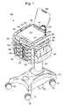
- FIG. 1is a perspective view of a first embodiment of a medical cart according to the present invention
- FIGS. 2A and 2Bare perspective views of a slidable laptop computer surface of the medical cart of FIG. 1 , the laptop surface being moveable forward ( FIG. 2A ) and rearward ( FIG. 2B );
- FIGS. 3A and 3Bare top and bottom exploded perspective views of three panels of a sliding platform of the medical cart of FIG. 1 ;
- FIG. 3Cis an enlarged view of a connection mechanism of the sliding platform of FIGS. 3A and 3B
- FIGS. 4A and 4Bare top plan views of the assembled sliding platform in which the platform has been pulled out to the right ( FIG. 4A ) and to the left ( FIG. 4B );
- FIGS. 5A-5Care close-up views of a barcode scanner and barcode scanner holder of the medical cart of FIG. 1 ;
- FIGS. 6A-6Care perspective views of a clipboard of the medical cart of FIG. 1 ;
- FIG. 7is a perspective view of a work platform of the medical cart of FIG. 1 without compartments;
- FIG. 8is a perspective view of different sized compartments configured to be inserted into the medical cart of FIG. 1 ;
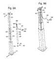
- FIG. 9Ais an exploded view of parts of a height adjustment mechanism of the medical cart of FIG. 1 ;
- FIG. 9Bis a perspective view of the height adjustment mechanism of FIG. 9A in assembled form
- FIGS. 10A and 10Bare bottom and top perspective views of the height adjustment mechanism of FIGS. 9A and 9B being connected to the medical cart of FIG. 1 ;
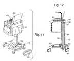
- FIG. 11is a rear perspective view of the medical cart of FIG. 1 having a laptop computer thereon and showing a hatch being removed;
- FIG. 12is cross-sectional side view of the medical cart of FIG. 1 ;
- FIG. 13is a rear perspective view of the medical cart of FIG. 1 having both a hatch and a base cover removed;
- FIG. 14is a rear perspective view of the medical cart of FIG. 1 showing a retractable power cord
- FIG. 15is an underside plan view of the medical cart of FIG. 1 showing a first locking mechanism
- FIG. 16is a perspective view of a second embodiment of a medical cart according to the present invention.
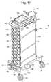
- FIG. 17is a perspective view of a first embodiment of a medication module according to the present invention.
- FIG. 18is a side plan view of the medication module of FIG. 17 ;
- FIG. 19is an underside plan view of the medication module of FIG. 17 showing first and second locking mechanisms
- FIG. 20is an underside perspective view of a plurality of medication modules of the type shown in FIG. 17 releaseably engaged to form a train;
- FIGS. 21A and 21Bare front and back perspective views of a medical cart of the type shown in FIG. 16 releaseably engaged with a medication module of the type shown in FIG. 17 ;
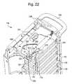
- FIG. 22is a breakaway perspective view of the medication module of FIG. 17 showing a portion of a keyless entry system
- FIG. 23shows a cross-sectional top view of the medication module of FIG. 17 showing a portion of a keyless entry system
- FIG. 24is a diagram of steps for an embodiment of a method of medication transport according to the present invention, which can be performed using a plurality of medication modules of the type shown in FIG. 17 and a plurality of medical carts of the types shown in FIGS. 1 and 16 .
- FIGS. 1-15A first embodiment of a medical cart 500 is shown in FIGS. 1-15 .
- the medical cart 500includes a work platform 340 , a support mechanism 320 that supports and adjusts the height of the work platform 340 , and a base 310 .
- the work platform 340can include a bi-directional laptop platform 370 , a bi-directional work surface 350 , an adjustable barcode scanner holder 380 , an adjustable clipboard 390 , one or more lockable compartments 530 , a plurality of top bins 342 , removable side bins 520 , cup holders 344 , and/or a keypad 238 . Because each of these items is provided on the work platform 340 , a user can ergonomically access each of these items as the work platform 340 is raised or lowered.
- the laptop platform 370can be configured to support, for example, a laptop computer 900 (shown in FIGS. 6A and 7 ). Conventional structure can be provided on the laptop platform 370 to hold the laptop computer in place.
- the laptop platform 370can have an arcuate front face 376 at a front portion. The arcuate front face 376 may be designed to correspond to the torso of a user for ergonomic reasons.
- the laptop platform 370can be locked in a central position ( FIG. 1 ) or adjusted ergonomically to a forward ( FIG. 2A ) or rearward ( FIG. 2B ) position.
- FIG. 1a central position
- FIG. 2Aa forward
- FIG. 2Ba forward
- a transfer structure 800allows the laptop platform 370 to be moved between those positions.
- the transfer structure 800can include stationary rails 372 mounted on body portions 802 of the work platform 340 and rails runners 373 mounted on the laptop platform 370 , as shown in FIGS. 2A and 2B .
- Notches 374which include sloped surfaces 375 and cavities 377 , are formed along the rail runners 373 .
- the notches 374are configured to engage posts 371 formed along the stationary rails 372 .
- the sloped surfaces 375 of the notches 374are configured to engage the posts 371 .
- the posts 371will ride up the sloped surfaces 375 and be deposited in cavities 377 in the notches 374 , thereby releasably immobilizing the laptop platform 370 with respect to the work platform 340 .
- one notch 374may be provided on each of the rail runners 373 and corresponding posts 371 may be provided on the stationary rails 372 .
- the laptop platform 370can be releaseably locked with respect to the work platform 340 .
- the posts 371may be provided at rear portions of the stationary rails 372 and the notches 374 may be similarly provided at rear portions of the rail runners 373 .
- the laptop platform 370will be releaseably locked with respect to the work platform 340 when in a central position shown in FIG. 1 .
- each of the stationary rails 372may include at least three posts 371 , one provided at each end of the stationary rails 372 and one provided in a central portion of the stationary rails 372 .
- each of the rail runners 373may include three notches 374 , one provided at each end of the rails runners 373 and one provided in a central portion of the rail runners 373 .
- the rearmost notches 374may be engaged with the forwardmost posts 371 .
- the forwardmost notches 374may be engaged with the rearmost posts 371 .
- all three posts 371 on each stationary rail 372may be engaged with the corresponding cavity 377 of the notches 374 of the rail runners 373 .
- the contact between the stationary rails 372 and the rail runners 373can be frictionally enhanced such that the laptop platform 370 does not readily slide with respect to the work platform 340 . Rather, force (i.e., either pushing or pulling on the laptop platform 370 ) will be required to overcome the frictional engagement between the stationary rails 372 and the rail runners 373 . As a result, the laptop platform 370 can be relatively fixed with respect to the work platform 340 at any location between a forwardmost position ( FIG. 2A ) and a rearmost position ( FIG. 2B ). In addition, one or more notches 374 /posts 371 may be combined with the frictional engagement between the stationary rails 372 and the rail runners 373 .
- the laptop platform 370When the laptop platform 370 is pushed forward or rearward, it can expose a secondary work area 379 provided below the laptop platform 370 .
- the secondary work area 379can be particularly sturdy. For example, it can be sturdy enough to enable a user to crush pills on the secondary work area 379 .
- the secondary work area 379may be provided with a rim 378 .
- the rim 378may reduce the likelihood of medication rolling off the medical cart 500 such as, for example, when a nurse tries to crush pills on the secondary work area 379 .
- the bi-directional work surface 350is shown in FIGS. 3A , 3 B, 3 C, 4 A, and 4 B. As shown in FIGS. 3A and 3B , the bi-directional work surface 350 is positioned below the laptop platform 370 . The bi-directional work surface 350 is designed to move through a slot 343 in the side 341 of the work platform 340 in leftward and rightward directions to provide additional work space.
- the work surface 350can have channels 355 , 357 on its underside that engage ribs 358 , 359 formed on a plate 361 provided on a body 329 of the work platform 340 .
- the channels 355 , 357are sized to receive the ribs 358 , 359 of the plate 361 .
- the channels 355 , 357are closed at one end. As a result, when the second bi-directional work surface 350 slides to the right (as shown in FIG. 4A ), the channels 355 will slide along the ribs 358 , 359 .
- the channels 355will slide past the ribs 359 on the left side of the plate 361 and will continue to slide along ribs 358 on the right side of the plate 361 .
- the second bi-directional work surface 350will stop sliding, however, when the closed ends 363 of the channels 355 abut the inner ends of ribs 358 .
- the channels 357will slide along the ribs 358 , 359 .
- the channels 357will slide past the ribs 358 on the right side of the plate 361 and will continue to slide along ribs 359 on the left side of the plate 361 .
- the second bi-directional work surface 350will stop sliding, however, when the closed ends 365 of the channels 357 abut the inner ends of the ribs 359 .
- the bi-directional work surface 350slides to the right or to the left, it slides in an arcuate path as a result of the channels 355 , 357 and ribs 358 , 369 (and the work surface 350 ) being arcuate in shape.
- the second bi-directional work surface 350is positioned closer to a user standing or sitting in front of the medical cart 500 when it is in an extended position.
- a releaseable locking mechanism 1000(shown best in FIG. 3C ) can be provided to hold the work surface 350 in a center position and to prevent it from sliding unintentionally.
- the second bi-directional work surface 350may be provided with a projection 354 having sloped surfaces 347 and a nesting region 346 .
- the plate 361may be provided with a moveable pin 356 which may be, for example, a ball spring plunger that is spring-biased in upward direction (i.e., toward the work surface 350 ).
- the moveable pin 356will initially be pushed downward relative to the plate 361 by the sloped surface 347 of the projection 354 . Subsequently, the pin 356 will extend upwards into the nesting region 346 of the projection 354 and become frictionally engaged therein, thereby releasably locking the work surface 350 with respect to the work platform 340 .
- a forceis applied to one of the exposed ends of the second bi-directional work surface 350 (to push the moveable pin 356 out of the nesting region 346 of the curved projection 354 ), thereby enabling the bi-directional work surface 350 to slide freely along the ribs 358 , 359 .
- additional movable pins 356may be provided in the plate 361 so as to enable the second bi-directional work surface 350 to be releasably locked in a corresponding number of positions.
- the adjustable barcode scanner holder 380includes a flexible neck 382 , a base 386 , and a holder portion 384 .
- the position of the holder portion 384can be adjusted.
- the vertical distance between the holder portion 384 and the laptop platform 370can be adjusted.
- the orientation of the holder portion 384can be adjusted between, for example, a holding position in which a barcode scanner 385 is maintained in an upright holding position ( FIG. 5B ) and a hands-free scanning position in which the holder portion 384 is adapted to hold an inverted (i.e., facing downward) barcode scanner 385 .
- the holder portion 384By holding the scanner 385 in the inverted position, the holder portion 384 enables a user to pass documents between the scanner 385 and the laptop platform 370 ( FIG. 5C ), without having to manually hold the scanner 385 (i.e., the scanner 385 may be operated in a hands-free manner). Moreover, the flexibility of the neck 382 enables the holder portion 384 to be adjusted to accommodate various barcode scanner sizes. In addition, the neck 382 is designed to rotate at the base 386 thereof so that a user can turn the barcode scanner holder 380 away from the laptop platform 370 , if desired.
- the barcode scanner 385may be an integral part of the medical cart 500 or may be detachable therefrom. If the barcode scanner 385 is an integral component of the medical cart 500 , its power cord 387 may be inserted into a power cord passage 327 and connected to an electrical receptacle 904 , as later explained in detail with respect to FIGS. 11-13 . By way of contrast, the barcode scanner 385 may receive the power necessary to operate it from a laptop computer 900 when it is plugged into a USB port of the laptop computer 900 .
- the adjustable clipboard 390is also designed to hold items in a hands-free manner.
- the clipboard 390includes a clip 392 for holding items, such as paper.
- the clipboard 390also includes conventional rails 394 attached to an L-shaped metal bracket 393 which connects the clipboard 390 to the laptop platform 370 , as shown best in FIG. 6C .
- the clipboard 390is designed to slide along the rails 394 to the left of the medical cart 500 .
- the clipboard 390can be moved from a central position ( FIG. 6B ) to left of the laptop computer to allow the user to view the documents clipped to the clip 392 , as shown in FIGS. 6A and 6C .
- the clipboard 390could be designed to move to the right.
- the plurality of compartments 530face the user and move up and down with the work platform 340 (i.e., they remain in the same position relative to the laptop platform 370 ), which are ergonomically desirable features.
- the compartments 530may be provided with labeling portions 570 , which allow labels to be displayed on the compartments 530 .
- the plurality of compartments 530enable a user (e.g., a nurse) to separately maintain medication for particular patients or for a particular room. For example, if a nurse is responsible for eight patients in a hospital ward, the medical cart 500 may be provided with a corresponding number of compartments 530 and the medication for each patient may be kept in a separate drawer assigned to that patient.
- the nursecould load the medication for all eight patients into eight separate drawers at one time (e.g., at the start of a medication pass) and at one location (e.g., at a pyxis machine), thereby reducing the need to travel to obtain the medication during the nurse's shift.
- the compartments 530have projections 531 which are configured to slide in grooves 533 formed on the interior walls of the medical cart 500 .
- the compartments 530 in FIG. 1are shown as having a generally uniform height, this is not required. In some embodiments the compartments 530 may have different heights.
- dividers 535which may be, for example, sheet metal.
- a tall space 537may be created.
- a tall compartment 530 Ethe height of which is substantially equal to height of the four short compartments 530 A-D when installed in the medical cart 500 , may be inserted into medication module 500 to substantially fill the space 537 .
- the tall compartment 530 Ewill readily slide into the medical cart 500 by means of the projections 531 which are configured to slide into the grooves 533 previously occupied by the projections 531 of the upper short compartment 530 A.
- different size compartments 530can be accommodated based on the desired application.
- the compartments 530may be lockable by means of a keyless entry system (the details of which are later described with respect to FIGS. 22 and 23 ). Thus, the potential for unauthorized access to the compartments 530 while the nurse is caring for a particular patient is small.
- the top bins 243are provided to house items such as paperclips, pencils, etc.
- the cup holders 344are provided to secure a number of medicine cups used to pass out medications.
- the removable side bins 520can be provided to hold items, such as trash or medical equipment.
- the side bins 520can be removably connected to the sides of the body 329 of the work platform 340 by conventional means, such as a hole and pin arrangement.
- the work platform 340may be raised and lowered by means of the support mechanism 320 .
- Thisprovides a sitting or standing user with easy access to the work surface 350 and its associated components (e.g., laptop platform 370 , work surface 350 , compartments 530 , etc.).
- the support mechanism 320allows the user to adjust the position of the work platform 340 to a comfortable position, regardless of whether the user is sitting or standing.
- the support mechanism 320comprises two telescoping portions 322 , 324 (shown more clearly in the embodiment shown in FIG. 16 ) and height adjustment mechanism 400 (shown in FIGS. 9A and 9B ).
- the height adjustment mechanism 400enables a standing user or a sitting user to ergonomically raise and lower the work platform 340 .
- the height adjustment mechanism 400includes an outer casing 410 , a telescoping inner casing 420 , and a driver 430 .
- two or more drawer slides 422are provided between the inner casing 420 and the outer casing 410 .
- two drawer slides 422may be used (on opposite sides of the inner casing 420 ), it is preferable to use at least three drawer slides 422 , to prevent (or at least greatly inhibit) a binding action from being applied to the height adjustment mechanism 400 by means of a cantilevered force being applied thereto.
- the drawer slides 422may be, for example, conventional drawer rails formed of stationary drawer rails 423 and corresponding rail runners 425 . If the drawer slides 422 are conventional drawer rails, one side of the drawer slides 422 (e.g., the rail runners 425 ) may be fixed to outer sides of the inner casing 420 and the corresponding side of the drawer slides 422 (e.g., the stationary drawer rails 423 ) may be fixed to inner sides the outer casing 420 . Further, the stationary drawer rails 423 may be provided with ball bearings to facilitate movement of the rail runner 425 . An upper end of one side of the inner casing 420 is provided with an engagement mechanism 426 . As shown, the engagement mechanism may be in the form of a window in the side of the casing 420 .
- the driver 430includes a gas driven piston 432 which, in turn, includes a body portion 436 and a telescoping strut 434 .
- the driver 430is controlled by an actuator 440 to which is connected by a connector 442 .
- a base 411 of the outer casing 410is affixed to the base 310 of the medical cart 500 by a plurality of bolts through the base 411 .
- a bolt 413passes through a hole 437 in a connection portion 439 of the body portion 436 of the piston 432 , thereby immobilizing both the outer casing 410 and the piston 432 .
- the inner casing 420 and the telescoping strut 434are affixed to work platform 340 by an upper bolt 415 which passes through the inner casing 420 and through a hole 459 in a connection portion 460 of the telescoping strut 434 .
- the actuator 440may be provided in a front portion of the medical cart 500 .
- a button 444 of the actuator 440may be provided in the handle 360 of the medical cart 500 , as shown in FIG. 1 .
- the button 444is pushed as a user pushes down on work platform 340 thereby causing the gas driven piston 432 to expel air.
- the telescoping strut 434is withdrawn vertically into the body portion 436 of the piston 432 .
- the work platform 340which is affixed to the telescoping strut 434 also moves downward.
- the work platform 340forces the connection portion 460 and the inner casing 420 to move downward. If the button 444 is released while the work platform 340 is being lowered, the work platform 340 will be releaseably locked at the height at which the button 444 is released. As a result, the work platform 340 can be releaseably locked at any position between a lowest position (at which the telescoping strut 434 is maximally provided in the body portion 436 of the piston 432 ) and a highest position (at which the inner casing 420 is driven upward to a maximum distance by the telescoping strut 434 of the piston 432 ).
- each component of the work platform 340(including the bi-directional laptop platform 370 and the compartments 530 ) is ergonomically available to a user when sitting or standing.
- the medical cartcan include a power cord passage 327 that enables a power cord 902 of a laptop computer 900 (or other device) on the laptop platform 370 to be electrically connected to an electrical receptacle 904 provided in the base 310 .
- the electrical receptacle 904can be connected, for example to a wall outlet via a retractable cord 906 , as later described.
- the passage 327includes an access hole 325 in the work platform 340 and extends through the telescoping portions 322 , 324 .
- the passage 327terminates in a well 960 in the base 310 where the electrical connection can occur. This permits the point of connection to the electrical receptacle 904 to be enclosed.
- the well 960 in the base 310houses the electrical receptacle 904 , a retractable cord 906 , and a hatch 908 that provides access to the well 960 so that power cords 387 , 902 can be plugged into the electrical receptacle 904 .
- the retractable cord 906can be plugged into an external wall outlet to recharge the battery internal to the laptop computer 900 and/or a battery-powered solenoid 240 in the keyless entry system (later described in detail).
- the hatch 908works in conjunction with a cover plate 910 to enclose the base 310 including the well 960 , thereby encapsulating the components provided in the base 310 and shielding them from the environment.
- the base 310which is moveable by means of rolling members 120 (e.g., casters), is ergonomically shaped to provide stability.
- the base 310is designed to provide stability by having the rolling members 120 at corners which are outside of the footprint of the work platform 340 .
- the rolling members 120are spaced-apart to such a degree that two rolling members 123 of a medication module 100 can be located between two rolling members 121 of the base 310 , thereby enabling the medical cart 500 and the medication module 100 to nest together.
- a second locking mechanism 190provided on an underside of the base 310 (shown in FIGS. 1 and 15 ), also as later described in detail.
- FIG. 16Another embodiment of a medical cart 300 is shown in FIG. 16 .
- the removable side bins 520 of the previous cart 500have been removed to facilitate joining the medical cart 300 with a medication module 100 .
- the medical cart 300like the medical cart 500 shown in FIG. 1 , also includes a second locking mechanism 190 which may be used to connect the medical cart 300 to a medication module 100 .
- the cart 300contains fewer compartments 330 which may, like the compartments 530 of the medical cart 500 shown in FIG. 1 , be lockable by means of a keyless entry system or by a conventional key lock.
- the medication module 100includes a component body 111 having a plurality of lockable compartments 130 and which is supported by a base 110 .
- the medication modulealso may include a refuse container 140 , a depression work surface 150 , a retractable power cord 144 (shown best in FIGS. 18 and 21B ) which can be used to recharge a battery 241 of a keyless entry system 600 by means of a power cord 233 (as later described in detail), a front handle 160 , and a side handle 162 .
- the two handles 160 , 162are provided so that the medication module can be pushed by a user standing in front of the compartments 130 or in front of the sidewall 112 .
- the component body 111includes two side walls 112 and a back wall 114 .
- the walls 112 , 114support a plurality of compartments 130 which, for example, may be in the form of drawers.
- the compartments 130are shown as having a generally uniform height, this is not required. Moreover, in some embodiments the compartments 130 may have different heights. As a result, a plurality of short compartments 130 may be replaced by a tall compartment 130 in the manner previously described with respect to the first medical cart 500 embodiment.
- the compartmentsmay be lockable by a keyless entry system 600 , as hereafter described with respect to FIGS. 22 and 23 .
- the keyless entry system 600includes a solenoid 240 (powered by a battery 241 which is electrically connected, by means of the power cord 233 , to the retractable power cord 144 ), a printed circuit board (“PCB”) 245 , a piston 222 , a spring-biased hinge 210 (which has an active side 211 and a stationary side 213 ), a keypad 238 , and an actuating lever 224 which is connected to the piston 222 at a connection point 231 and which pivots around an axis of rotation defined by a pin 230 .
- a solenoid 240powered by a battery 241 which is electrically connected, by means of the power cord 233 , to the retractable power cord 144
- PCBprinted circuit board
- the hinge 210can be, for example, a hinge conventionally known as a piano hinge.
- the active side 211 of the hinge 210is provided in an engagement position 215 in which the active side 211 is positioned to engage a notch 132 formed on a compartment 130 (i.e., each compartment 130 has a similar notch 132 ), if a user attempts to withdraw the compartment 130 .
- the compartments 130can not be readily withdrawn out of the medication module 100 .
- a userTo unlock the compartments 130 , a user first enters a security code using buttons of the keypad 238 (to verify access to the medication module 100 ) and may, if required, then enter an unlock code on the keypad 238 .
- the PCB 245sends an unlock signal to the solenoid 240 .
- the solenoid 240withdraws the piston 222 , thereby causing the end of actuating lever 224 in contact with the active side 211 of the spring 210 to swing outward on the pin 230 .
- the actuating lever 224causes the active side 211 of the spring 210 to swing out of the engagement position 215 and into a disengagement position 217 .
- the active side 211swings toward the stationary side 213 of the spring 210 so that the two sides 211 , 213 rest against each other.
- the notches 132 of the compartments 130will no longer be inhibited by the active side 211 of the spring 210 .
- the compartments 130may be readily removed from the medication module 100 .
- the compartments 130can be relocked by pressing a “lock” button (not labeled) on the keypad 238 or by entering a lock code on the keypad 238 ; in either case, the PCB 245 will send a lock signal to the solenoid 240 instructing it to outwardly push the piston 222 , thereby causing the end of the actuating lever 224 in contact with the active side 211 of the spring 210 to swing inward on the pin 230 . As a result, the active side 211 of the spring 210 will swing back into the engagement position 215 by means of the spring-biased nature of the spring 210 .
- a timermay be provided in the keypad 238 , PCB 245 , or in the solenoid 240 which will, when a timer count is satisfied, automatically instruct the piston 222 to be outwardly pushed, thereby causing the active side 211 of the spring 210 to retract into the engagement position 215 .
- the compartment 130may be inserted into the medication module without entering an unlock code.
- the notches 132 of the compartments 130have sloped faces 133 thereon which, when the compartment 130 is pushed into the medication module 100 , will abut the active side 211 of the spring 210 .
- the sloped face 133will cause the active side 211 of the spring 210 to collapse into the disengagement position 217 , i.e., the spring-bias of the spring 210 will be overcome.
- the active side 211will snap back into the engagement position 215 (by means of the spring-bias), thereby locking the compartment 130 in the medication module 100 .
- An additional safety (and access) measuremay be provided to address a situation in which the keypad 238 fails or the battery powered solenoid 240 loses power.
- the compartments 130may be unlocked manually by a hard (back-up) lock 220 , as shown in FIGS. 17 and 23 .
- a keycan be used to manually rotate the actuating lever 224 , thereby pushing the active side 211 of the spring 210 or enabling it to swing outward under the force of the spring bias.
- the keycan be used to move the active side 211 manually out of the engagement position 215 or to allow the active side 211 to swing (under the spring-biased force) into the engagement position 215 .
- the keyless entry system 600has been described with respect to the medication module 100 , the same system 600 can be applied to the compartments 330 , 530 of the medical carts 300 , 500 , respectively.
- a nursecan use a medication module 100 and/or medical cart 300 , 500 to deliver medication to various patients, without worrying about unauthorized access to the compartments 130 , 330 , 530 while attending to a particular patient.
- a nursedoes not have to worry about losing a key, except for the hard lock key which may be kept at a central location.
- the base 110which is supported by a plurality of rolling members 120 (e.g., casters), is designed to provide stability to the frame 111 , similar to the base 310 of the medical cart 300 , 500 .
- the base 110is also designed such that the two of the rolling members 121 on one side of the module 100 are spaced apart farther than the two rolling members 123 on the other side of the module 100 .
- the closer spaced rolling members 123 of one module 100can fit between the farther spaced rolling members 121 of the other module 100 (or medical cart 300 , 500 ), thereby enabling the modules 100 (or module 100 and medical cart 300 , 500 ) to nest closer together to form a train 200 .
- the sidewalls 112 , 112 of adjacent modules 100can be positioned in close proximity, thereby creating a small footprint for the train 200 .
- the compartments of the medication module 100can be in close proximity to the work platform 340 of the medical cart 300 , 500 , thereby providing a user with easy access thereto.
- the base 110 of the medication module 100is provided with a connection mechanism 171 .
- the connection mechanism 171includes an actuator 180 , a first locking mechanism 170 , and a second locking mechanism 190 , as best shown in FIGS. 19 and 20 .
- the actuator 180which may be in the form of a foot pedal, includes a pivot rod 182 . When the foot pedal 180 is depressed, the pivot rod 182 is configured to rotate within rings 192 from a resting position to an active position, thereby activating the first locking mechanism 170 .
- the first locking mechanism 170includes beams 188 , cover plates 186 having sloped surfaces 194 , and catches 184 which comprise cavities 187 .
- the rod 182 of the actuator 180rotates, it pulls the beams 188 toward the center of the base 110 .
- the beams 188cause the cover plates 186 to rotate toward the center of the base 110 .
- the cover plates 186expose the cavities 187 in the catches 184 .
- the actuator 180is released, the rod 182 rotates back to the resting position, thereby pushing the beams 188 away from the center of the base 110 and, in turn, rotating the cover plates 186 to enclose the cavities 187 .
- the cavities 187When the cavities 187 are closed, they are designed to releaseably contain posts 197 of a second locking mechanism 190 of another medication module 100 or of a medical cart 300 , 500 .
- the posts 197may be provided separately on the base 110 , 310 , of the medication module 100 and medical carts 300 , 500 , they are preferably integrally formed by means of a crossbar 196 . Regardless of the design of the posts 197 , they enable a medication module 100 to be joined to another medication module 100 to form a train 200 , as shown in FIG. 20 .
- a train 200 of medication modules 100 A- 100 Ccan be formed by releaseably aligning the posts 197 of a second locking mechanism 190 of one medication module 100 A with the cover plates 186 of a first locking mechanism 170 of an adjacent medication module 100 B.
- the posts 197will slide along the sloped surfaces 194 of the cover plates 186 , thereby causing the cover plates 186 to rotate.
- the cover plates 186rotate, the cavities 187 will be exposed and the posts 197 will slide into them.
- the cover plates 186will retract, thereby locking the posts 197 in the cavities.
- the posts 197 of the second medication module 100 Bwould be similarly inserted into the cavities 187 of the third medication module 100 C.
- the medication modulecan be releaseably joined with the medical carts 300 , 500 .
- the medication module 100can be releaseably joined with the medical cart 300 shown in FIG. 16 .
- a usere.g., a nurse
- the foot pedal actuator 180shown in FIG. 21A
- a train 200 of medication modules 100can be loaded with medication at a central location (e.g., pharmacy) 700 ; the number of medication modules 100 may depend on the number of medical carts 300 , 500 that a hospital has on a particular floor on which the medication is to be delivered.
- a pharmacy techniciancan then drive the train 200 to a second location 800 at which the individual medication modules 100 can be separated from the train 200 .
- the medication modules 100may be joined (by means of the first connection mechanism 171 thereon) to a medical cart 300 , 500 (by means of the second locking mechanism 190 thereon).
- One or more nurses 750can then drive the separated medication modules 100 (with or without a medical cart 300 , 500 affixed thereto) to respective third locations (not shown) at which the nurse may administer medication (contained in the compartments 130 ) to a distinct plurality of patients.
- the empty medication modules 100can be separated from attached medical carts 300 , 500 (if any) and rejoined to form a train 200 of medication modules 100 .
- the train 200 of medication modules 100may then be returned to the central location 700 for refilling so that the method of medication transport may be repeated.
- a modificationmay be made. Specifically, there may arise situations in which a nurse 750 does not want to push a combined medication module 100 and medical cart 300 , 500 but wants to enjoy the functionality of the medical cart 300 , 500 . In these situations, the nurse 750 may unlock the compartments 130 of medication module 100 at the second location 800 and remove one or more compartments 130 . The removed compartments 130 could then be exchanged with compartments 530 in the medical cart 500 or placed on the work platform of the medical cart 300 so that the medical cart 300 , 500 then contains the medications which the nurse 750 needs to deliver.
- the medication modules 100 containing the empty compartments 530 of the medical carts 500may then be taken back to central location 700 for refilling while the original medication is being taken by nurses to the patients, so that the method of medication transport can be repeated.
Landscapes
- Health & Medical Sciences (AREA)
- Engineering & Computer Science (AREA)
- Biomedical Technology (AREA)
- Nursing (AREA)
- Life Sciences & Earth Sciences (AREA)
- Animal Behavior & Ethology (AREA)
- General Health & Medical Sciences (AREA)
- Public Health (AREA)
- Veterinary Medicine (AREA)
- Chemical & Material Sciences (AREA)
- Combustion & Propulsion (AREA)
- Transportation (AREA)
- Mechanical Engineering (AREA)
- Accommodation For Nursing Or Treatment Tables (AREA)
Abstract
Description
Claims (7)
Priority Applications (5)
| Application Number | Priority Date | Filing Date | Title |
|---|---|---|---|
| US12/193,346US7594668B2 (en) | 2003-02-24 | 2008-08-18 | Medical cart, medication module, height adjustment mechanism, and method of medication transport |
| US12/550,771US20090319079A1 (en) | 2003-02-24 | 2009-08-31 | Medical cart, medication module, height adjustment mechanism, and method of medication transport |
| US13/187,328US8215650B2 (en) | 2003-02-24 | 2011-07-20 | Medical cart, medication module, height adjustment mechanism, and method of medication transport |
| US13/544,922US20120274196A1 (en) | 2003-02-24 | 2012-07-09 | Medical cart, medication module, height adjustment mechanism, and method of medicaton transport |
| US13/942,463US9242664B2 (en) | 2003-02-24 | 2013-07-15 | Medical cart, medication module, height adjustment mechanism, and method of medication transport |
Applications Claiming Priority (6)
| Application Number | Priority Date | Filing Date | Title |
|---|---|---|---|
| US44892003P | 2003-02-24 | 2003-02-24 | |
| US48465803P | 2003-07-07 | 2003-07-07 | |
| US51864903P | 2003-11-12 | 2003-11-12 | |
| US53290003P | 2003-12-30 | 2003-12-30 | |
| US10/783,030US20040262867A1 (en) | 2003-02-24 | 2004-02-23 | Medical cart, medication module, height adjustment mechanism, and method of medication transport |
| US12/193,346US7594668B2 (en) | 2003-02-24 | 2008-08-18 | Medical cart, medication module, height adjustment mechanism, and method of medication transport |
Related Parent Applications (1)
| Application Number | Title | Priority Date | Filing Date |
|---|---|---|---|
| US10/783,030ContinuationUS20040262867A1 (en) | 2003-02-24 | 2004-02-23 | Medical cart, medication module, height adjustment mechanism, and method of medication transport |
Related Child Applications (1)
| Application Number | Title | Priority Date | Filing Date |
|---|---|---|---|
| US12/550,771DivisionUS20090319079A1 (en) | 2003-02-24 | 2009-08-31 | Medical cart, medication module, height adjustment mechanism, and method of medication transport |
Publications (2)
| Publication Number | Publication Date |
|---|---|
| US20090015116A1 US20090015116A1 (en) | 2009-01-15 |
| US7594668B2true US7594668B2 (en) | 2009-09-29 |
Family
ID=33545637
Family Applications (6)
| Application Number | Title | Priority Date | Filing Date |
|---|---|---|---|
| US10/783,030AbandonedUS20040262867A1 (en) | 2003-02-24 | 2004-02-23 | Medical cart, medication module, height adjustment mechanism, and method of medication transport |
| US12/193,346Expired - LifetimeUS7594668B2 (en) | 2003-02-24 | 2008-08-18 | Medical cart, medication module, height adjustment mechanism, and method of medication transport |
| US12/550,771AbandonedUS20090319079A1 (en) | 2003-02-24 | 2009-08-31 | Medical cart, medication module, height adjustment mechanism, and method of medication transport |
| US13/187,328Expired - Fee RelatedUS8215650B2 (en) | 2003-02-24 | 2011-07-20 | Medical cart, medication module, height adjustment mechanism, and method of medication transport |
| US13/544,922AbandonedUS20120274196A1 (en) | 2003-02-24 | 2012-07-09 | Medical cart, medication module, height adjustment mechanism, and method of medicaton transport |
| US13/942,463Expired - LifetimeUS9242664B2 (en) | 2003-02-24 | 2013-07-15 | Medical cart, medication module, height adjustment mechanism, and method of medication transport |
Family Applications Before (1)
| Application Number | Title | Priority Date | Filing Date |
|---|---|---|---|
| US10/783,030AbandonedUS20040262867A1 (en) | 2003-02-24 | 2004-02-23 | Medical cart, medication module, height adjustment mechanism, and method of medication transport |
Family Applications After (4)
| Application Number | Title | Priority Date | Filing Date |
|---|---|---|---|
| US12/550,771AbandonedUS20090319079A1 (en) | 2003-02-24 | 2009-08-31 | Medical cart, medication module, height adjustment mechanism, and method of medication transport |
| US13/187,328Expired - Fee RelatedUS8215650B2 (en) | 2003-02-24 | 2011-07-20 | Medical cart, medication module, height adjustment mechanism, and method of medication transport |
| US13/544,922AbandonedUS20120274196A1 (en) | 2003-02-24 | 2012-07-09 | Medical cart, medication module, height adjustment mechanism, and method of medicaton transport |
| US13/942,463Expired - LifetimeUS9242664B2 (en) | 2003-02-24 | 2013-07-15 | Medical cart, medication module, height adjustment mechanism, and method of medication transport |
Country Status (1)
| Country | Link |
|---|---|
| US (6) | US20040262867A1 (en) |
Cited By (53)
| Publication number | Priority date | Publication date | Assignee | Title |
|---|---|---|---|---|
| US20080033893A1 (en)* | 2006-08-07 | 2008-02-07 | E.F. Bavis & Associates, Inc. | Apparatus and methods for an equipment stand for a drive-thru employee station |
| US20080104300A1 (en)* | 2006-10-31 | 2008-05-01 | Sonosite, Inc. | Docking station having auxiliary power management for use with portable medical equipment |
| US20090206713A1 (en)* | 2008-02-18 | 2009-08-20 | Vilkas Vesa Juhani | Movable equipment for medical environment |
| US20090212670A1 (en)* | 2008-02-21 | 2009-08-27 | Rubbermaid Incorporated | Medical cart and drawer assembly and lock |
| US20090256454A1 (en)* | 2008-04-15 | 2009-10-15 | Zag Industries, Ltd. | Containers and container system |
| USD613866S1 (en)* | 2009-07-30 | 2010-04-13 | Electro-Optical Sciences, Inc. | Medical cart |
| USD613867S1 (en)* | 2009-07-30 | 2010-04-13 | Electro-Optical Sciences, Inc. | Table structure of a medical cart |
| US20100145160A1 (en)* | 2006-08-30 | 2010-06-10 | Jacques Cinqualbre | Multimedia, multiservice and connectable mobile assembly for diagnosis, prescriptions, medical checkups and nursing care |
| US20100148458A1 (en)* | 2008-12-12 | 2010-06-17 | Nellcor Puritan Bennett Llc | Medical Ventilator Cart |
| US20100171398A1 (en)* | 2009-01-03 | 2010-07-08 | Gilles Berthiaume | Desk |
| USD625014S1 (en) | 2010-03-12 | 2010-10-05 | Sonosite, Inc. | Medical device stand docking head |
| USD625015S1 (en) | 2010-03-12 | 2010-10-05 | Sonosite, Inc. | Medical device stand docking station |
| US20110025007A1 (en)* | 2009-07-30 | 2011-02-03 | Christiano Butler | Medical cart |
| US20110024507A1 (en)* | 2009-07-30 | 2011-02-03 | Kazuna Tanaka | Storage card |
| USD632797S1 (en) | 2008-12-12 | 2011-02-15 | Nellcor Puritan Bennett Llc | Medical cart |
| USD632796S1 (en) | 2008-12-12 | 2011-02-15 | Nellcor Puritan Bennett Llc | Medical cart |
| USD643535S1 (en) | 2009-12-04 | 2011-08-16 | Nellcor Puritan Bennett Llc | Medical ventilator |
| US20110232535A1 (en)* | 2010-03-25 | 2011-09-29 | Modernsolid Industrial Co., Ltd. | Medical worktable |
| US8210548B1 (en)* | 2008-08-15 | 2012-07-03 | June Agyemang | Portable nursing service cart and associated method |
| US20120203377A1 (en)* | 2006-08-21 | 2012-08-09 | Omnicell, Inc. | Medication dispensing cart |
| US20120245731A1 (en)* | 2006-02-11 | 2012-09-27 | Omnicell, Inc. | Medication dispensing cart |
| US8398408B1 (en) | 2009-02-25 | 2013-03-19 | Sonosite, Inc. | Charging station for cordless ultrasound cart |
| US20130178977A1 (en)* | 2007-02-23 | 2013-07-11 | Cerner Innovation, Inc. | Medication dispensing apparatus |
| US8662605B2 (en) | 2011-02-18 | 2014-03-04 | Rubbermaid Incorporated | Mobile technology cabinet |
| US20140218282A1 (en)* | 2013-02-01 | 2014-08-07 | Modernsolid Industrial Co., Ltd. | Medical Cart |
| USD722696S1 (en)* | 2013-02-07 | 2015-02-17 | Maquet Critical Care Ab | Ventilator bottom plate |
| USD730011S1 (en)* | 2014-02-21 | 2015-05-19 | Rubbermaid Commercial Products Llc | Cart |
| US9039016B2 (en) | 2012-02-08 | 2015-05-26 | Humanscale Corporation | Accessory cart |
| US20150340892A1 (en)* | 2014-05-21 | 2015-11-26 | Palmer Hamilton, Llc | Mobile charging table |
| US9242664B2 (en) | 2003-02-24 | 2016-01-26 | Capsa Solutions, Llc | Medical cart, medication module, height adjustment mechanism, and method of medication transport |
| USD760390S1 (en)* | 2014-11-25 | 2016-06-28 | Maquet Critical Care Ab | Ventilator |
| US9451931B2 (en)* | 2012-03-29 | 2016-09-27 | Hitachi Aloka Medical, Ltd. | Carriage for ultrasonic diagnosis device |
| USD775345S1 (en) | 2015-04-10 | 2016-12-27 | Covidien Lp | Ventilator console |
| USD802337S1 (en) | 2016-10-10 | 2017-11-14 | Michael C. Smith | Office bureau and hanging rack |
| US9955784B1 (en) | 2017-03-01 | 2018-05-01 | Michael C. Smith | System and method for making a mobile office bureau with simultaneous viewing recharging station |
| US20190144054A1 (en)* | 2017-11-13 | 2019-05-16 | Eric Bliss | Stair-climbing remote control utility wagon |
| US10386014B2 (en)* | 2017-12-22 | 2019-08-20 | Xu Bo Pei | Desk platform structure for fitness bike |
| USD863559S1 (en) | 2013-03-01 | 2019-10-15 | Capsa Solutions, Llc | Hospital cart |
| US10453572B1 (en) | 2012-03-01 | 2019-10-22 | Capsa Solutions, Llc | System and method for a hospital cart |
| US10525302B2 (en)* | 2016-04-06 | 2020-01-07 | Xubo Pei | Indoor fitness bicycle |
| USD883718S1 (en)* | 2018-07-25 | 2020-05-12 | Eastern Global Corporation | Multipurpose cabinet |
| US10751239B2 (en) | 2015-11-13 | 2020-08-25 | Humanscale Corporation | Medical technology station and method of use |
| US11234787B1 (en) | 2020-11-20 | 2022-02-01 | Stryker Corporation | Manifold for filtering medical waste being drawn under vacuum into a medical waste collection system |
| US11254340B2 (en) | 2019-03-15 | 2022-02-22 | Covidien Lp | Cart for medical equipment |
| US20220089041A1 (en)* | 2019-01-07 | 2022-03-24 | Green Cubes Technology, Llc | Mobile, nesting, battery powered kiosk |
| US20220218548A1 (en)* | 2018-05-22 | 2022-07-14 | Brushtime Enterprises, Llc | Dental care systems and methods |
| US11426008B2 (en)* | 2015-04-25 | 2022-08-30 | Kids2, Inc. | Convertible high chair |
| US11613286B2 (en) | 2019-09-06 | 2023-03-28 | Covidien Lp | Cart for medical equipment |
| US11684444B2 (en) | 2019-05-02 | 2023-06-27 | Stryker Corporation | Height adjustable kick bucket and height adjustable stand |
| US11786647B1 (en) | 2022-01-31 | 2023-10-17 | Stryker Corporation | Medical waste collection systems, manifolds, and related methods |
| US11877671B2 (en) | 2015-04-25 | 2024-01-23 | Kids2, Inc. | Convertible high chair |
| US12077202B2 (en) | 2020-11-10 | 2024-09-03 | Milwaukee Electric Tool Corporation | Moveable storage and carrying device |
| US12357410B2 (en) | 2020-01-21 | 2025-07-15 | Stryker Corporation | Height adjustable medical bucket |
Families Citing this family (119)
| Publication number | Priority date | Publication date | Assignee | Title |
|---|---|---|---|---|
| US8191909B2 (en)* | 2005-01-10 | 2012-06-05 | Livengood Engineering, Inc. | Modular patient support system |
| US20070131577A1 (en)* | 2005-12-08 | 2007-06-14 | Virginia Call | Integrated institutional first aid kit |
| US8460223B2 (en)* | 2006-03-15 | 2013-06-11 | Hill-Rom Services Pte. Ltd. | High frequency chest wall oscillation system |
| US20070228680A1 (en)* | 2006-04-03 | 2007-10-04 | Metro Industries Inc. | Modular Workstation |
| USD577874S1 (en) | 2006-04-17 | 2008-09-30 | The Vollrath Company, L.L.C. | Cart post |
| US7800914B2 (en)* | 2006-06-08 | 2010-09-21 | David Dully | Apparatus and method for storing and regulating access to portable electronic devices |
| US7828253B2 (en)* | 2006-06-20 | 2010-11-09 | Meyer Christopher E | Secure shelf for technology workstand |
| TWI326437B (en)* | 2006-12-29 | 2010-06-21 | Chimei Innolux Corp | Display device |
| US20080221930A1 (en) | 2007-03-09 | 2008-09-11 | Spacelabs Medical, Inc. | Health data collection tool |
| EP2162667A1 (en)* | 2007-06-18 | 2010-03-17 | Rubbermaid Incorporated | Cart with flexible cable carrier |
| US9962316B2 (en)* | 2007-10-30 | 2018-05-08 | Carefusion 303, Inc. | Managing medications at the bedside |
| USD628701S1 (en)* | 2007-11-13 | 2010-12-07 | Maquet Critical Care Ab | Medical device |
| DE102008026989B3 (en)* | 2008-06-05 | 2009-09-03 | Dräger Medical AG & Co. KG | Fastening device, medical device and device system with such a fastening device |
| WO2010027527A1 (en)* | 2008-09-08 | 2010-03-11 | New York Blood Center, Inc. | Mobile medical supply, sample collection and transport system |
| USD619264S1 (en)* | 2008-10-02 | 2010-07-06 | Livengood Engineering, Inc. | Patient support cart |
| CA2737630C (en) | 2008-11-05 | 2016-08-30 | Ecolab Inc. | Cleaning trolley |
| USD620121S1 (en)* | 2008-12-19 | 2010-07-20 | Unetixs Vascular, Inc. | Cart for a medical device |
| US8103379B2 (en)* | 2009-01-09 | 2012-01-24 | Automed Technologies, Inc. | Medication cabinetry |
| US8744621B2 (en) | 2009-01-09 | 2014-06-03 | Automed Technologies, Inc. | Medical cabinet access belt optimization system |
| US8588966B2 (en)* | 2009-01-09 | 2013-11-19 | Automed Technologies, Inc. | Cabinet system |
| US9121197B2 (en) | 2009-01-09 | 2015-09-01 | Automed Technologies, Inc. | Cabinet system with improved drawer security |
| US8191487B2 (en)* | 2009-02-25 | 2012-06-05 | Humanscale Corporation | Wall-mounted accessory holder |
| US20100213679A1 (en)* | 2009-02-25 | 2010-08-26 | Shaun Smith | Accessory Cart |
| US20100213328A1 (en)* | 2009-02-25 | 2010-08-26 | Shaun Smith | Apparatus and Method for Retaining a Computer Input Device |
| GB0906666D0 (en)* | 2009-04-17 | 2009-06-03 | Hospital Metalcraft Ltd | Cabinet |
| US20110068562A1 (en)* | 2009-09-18 | 2011-03-24 | Keffeler Mark G | Medication cart |
| BR112012011575A2 (en)* | 2009-10-16 | 2018-05-02 | Spacelabs Healthcare Llc | integrated and extensible anesthesia system |
| CN102667423B (en) | 2009-10-16 | 2016-06-08 | 太空实验室健康护理有限公司 | light enhanced flow tube |
| US9022492B2 (en)* | 2010-12-17 | 2015-05-05 | Spacelabs Healthcare Llc | Sliding track and pivot mounting system for displays on anesthesia machines |
| US9604020B2 (en) | 2009-10-16 | 2017-03-28 | Spacelabs Healthcare Llc | Integrated, extendable anesthesia system |
| USD624271S1 (en) | 2009-11-03 | 2010-09-21 | Ecolab Inc. | Cleaning trolley |
| USD624270S1 (en) | 2009-11-03 | 2010-09-21 | Ecolab Inc. | Cleaning trolley |
| USD624724S1 (en) | 2009-11-03 | 2010-09-28 | Ecolab Inc. | Cleaning trolley |
| USD624269S1 (en) | 2009-11-03 | 2010-09-21 | Ecolab Inc. | Cleaning trolley |
| US11954551B2 (en) | 2009-12-07 | 2024-04-09 | Meps Real-Time, Inc. | Modular system and method to establish tracking activation field |
| CH702337A1 (en)* | 2009-12-08 | 2011-06-15 | Wiegand Ag | Delivery system for drugs. |
| US8746908B2 (en) | 2010-01-27 | 2014-06-10 | Automed Technologies, Inc. | Medical supply cabinet with lighting features |
| CA2789479C (en)* | 2010-02-09 | 2016-06-21 | Meps Real-Time, Inc. | Self-contained rfid-enabled drawer module |
| EP3503115A3 (en) | 2010-03-21 | 2019-10-23 | Spacelabs Healthcare LLC | Patient monitoring system |
| FR2959661B1 (en)* | 2010-05-07 | 2013-04-12 | Decide Life Internat Sa | MEDICAL CARE TROLLEY |
| CN101884579B (en)* | 2010-07-15 | 2012-02-01 | 李长杰 | Elevator mechanism of electronic ward round cart |
| US8839724B2 (en) | 2010-08-20 | 2014-09-23 | Symmetry Medical Manufacturing, Inc. | Modular medical instrument table |
| US8286794B1 (en)* | 2010-11-02 | 2012-10-16 | Victor Agadzi | Medical organizer |
| WO2012068567A1 (en) | 2010-11-19 | 2012-05-24 | Spacelabs Healthcare, Llc | Dual serial bus interface |
| US9629566B2 (en) | 2011-03-11 | 2017-04-25 | Spacelabs Healthcare Llc | Methods and systems to determine multi-parameter managed alarm hierarchy during patient monitoring |
| US9367984B2 (en)* | 2011-04-14 | 2016-06-14 | GCX Corporation | Enhanced modular drawer structures, systems, and methods |
| WO2013008868A1 (en)* | 2011-07-12 | 2013-01-17 | 株式会社岡村製作所 | Cart device |
| US8714453B2 (en)* | 2011-08-09 | 2014-05-06 | The Code Corporation | Multi-functional cable apparatus for a barcode reader |
| USD711001S1 (en)* | 2011-08-29 | 2014-08-12 | General Electric Company | Anesthesiology machine |
| DE102011087589B4 (en)* | 2011-11-03 | 2016-04-21 | Siemens Aktiengesellschaft | Modular assistance systems |
| CA2863181C (en)* | 2012-02-03 | 2016-12-06 | Ergotron, Inc. | Computing cart with sliding work surface |
| USD707360S1 (en)* | 2012-02-06 | 2014-06-17 | Samsung Electronics Co., Ltd. | Medical ultrasound device |
| WO2013158657A1 (en)* | 2012-04-18 | 2013-10-24 | Volcano Corporation | Integrated support structures for mobile medical systems |
| USD714453S1 (en) | 2012-08-30 | 2014-09-30 | Guided Therapeutics, Inc. | Hand held unit for diagnostics or measurement |
| US9463069B2 (en)* | 2012-10-23 | 2016-10-11 | Spinesmith Partners, L.P. | Automated work station for point-of-care cell and biological fluid processing |
| DE202012104316U1 (en)* | 2012-11-09 | 2012-11-28 | Optiplan Gesellschaft für optische Planungsgeräte mbH | monitor |
| US8919896B1 (en)* | 2012-11-16 | 2014-12-30 | Lee-Ann Shewchuck | Portable tool chest |
| USD714454S1 (en)* | 2012-11-30 | 2014-09-30 | Ricoh Company, Ltd. | Medical cart |
| USD722172S1 (en)* | 2012-11-30 | 2015-02-03 | Ricoh Company, Ltd. | Medical cart |
| US20140155827A1 (en) | 2012-12-03 | 2014-06-05 | Mylan, Inc. | Medicament information system and method |
| US9643770B2 (en) | 2012-12-03 | 2017-05-09 | Mylan Inc. | System and method for medicament storage, dispensing, and administration |
| US9887562B2 (en) | 2012-12-03 | 2018-02-06 | Covidien Lp | Smart cart |
| US9179260B2 (en) | 2012-12-03 | 2015-11-03 | Mylan Inc. | Medicament information system and method |
| US9692829B2 (en) | 2012-12-03 | 2017-06-27 | Mylan Inc. | Medication delivery system and method |
| JP5863688B2 (en)* | 2013-02-28 | 2016-02-17 | 京セラドキュメントソリューションズ株式会社 | Image forming apparatus |
| US10987026B2 (en) | 2013-05-30 | 2021-04-27 | Spacelabs Healthcare Llc | Capnography module with automatic switching between mainstream and sidestream monitoring |
| US9475514B2 (en)* | 2013-11-11 | 2016-10-25 | Capsa Solutions | Medical carts with touch-sensitive foot panels, and associated apparatuses and methods |
| ES2449668B2 (en)* | 2013-12-02 | 2014-10-31 | Krz, S.L. | Trolley for dispensing medical devices |
| US9661923B2 (en)* | 2013-12-31 | 2017-05-30 | John Stephen Lanphear | Table and accessory unit assembly and method of docking accessory unit to table |
| WO2015120557A1 (en)* | 2014-02-17 | 2015-08-20 | Claronav Inc. | Medical cart |
| CN106456446B (en)* | 2014-03-24 | 2019-09-27 | 接触点医疗有限公司 | Medication dispensing method and device |
| US9472966B2 (en) | 2014-06-19 | 2016-10-18 | Covidien Lp | Surgical tray assemblies for storing, charging, powering, and/or communicating with surgical instruments |
| TWD170599S (en)* | 2014-08-14 | 2015-09-21 | 美爾敦股份有限公司 | Portion of platform of medicine trolley |
| USD754353S1 (en)* | 2014-09-05 | 2016-04-19 | Welch Allyn, Inc. | Medical device |
| USD816849S1 (en)* | 2014-10-10 | 2018-05-01 | Clear Recovery Systems, Llc | Walker apparatus |
| US10643174B1 (en)* | 2014-12-11 | 2020-05-05 | Amazon Technologies, Inc. | Dynamic item facing |
| US9474670B2 (en)* | 2014-12-18 | 2016-10-25 | Krz, S.L. | Cart for dispensing health products |
| EP3241166A4 (en)* | 2014-12-31 | 2018-10-03 | Vector Medical, LLC | Process and apparatus for managing medical device selection and implantation |
| US9895201B2 (en)* | 2015-02-27 | 2018-02-20 | Flex Operating Room, Llc | Cantilever organizational rack system for supporting surgical instrumentation |
| USD857902S1 (en)* | 2015-03-11 | 2019-08-27 | General Electric Company | Breathing apparatus for an anesthesia machine |
| USD787073S1 (en) | 2015-03-12 | 2017-05-16 | Lgms, Llc | Patient support cart with mounting plate |
| USD783389S1 (en) | 2015-03-12 | 2017-04-11 | Lgms, Llc | Mounting plate for a patient support cart |
| US9720444B2 (en) | 2015-03-23 | 2017-08-01 | Ryan Nicholas HOLDEN | Furniture system for computer system having integral display |
| CN105105957B (en)* | 2015-09-26 | 2017-06-30 | 李智 | A kind of pharmaceutical Dispensing System |
| USD806340S1 (en)* | 2015-12-23 | 2017-12-26 | General Electric Company | Cart |
| USD810305S1 (en)* | 2016-03-29 | 2018-02-13 | Beijing East Whale Image Technology Co., Ltd. | Pushcart |
| CN105943287A (en)* | 2016-05-09 | 2016-09-21 | 山西医科大学第二医院 | Clinical blood collecting vehicle |
| US20180021104A1 (en)* | 2016-07-20 | 2018-01-25 | Biolase, Inc. | Dental laser system and method |
| CN106264739A (en)* | 2016-07-25 | 2017-01-04 | 无锡福镁轻合金科技有限公司 | A kind of medical treatment is made the rounds of the wards go-cart |
| CN106074060A (en)* | 2016-08-09 | 2016-11-09 | 上海中科再启医疗设备有限公司 | Movable cart lowering or hoisting gear |
| USD857210S1 (en)* | 2016-09-05 | 2019-08-20 | Optimedica Corporation | Base with wheels for a mobile patient bed |
| US9642455B1 (en)* | 2016-11-01 | 2017-05-09 | Sherry Albert | Overbed caddy cart |
| WO2018114209A2 (en)* | 2016-12-21 | 2018-06-28 | Service-Konzepte MM AG | Autonomous domestic appliance and seating or reclining furniture as well as domestic appliance |
| US10286939B2 (en) | 2017-05-18 | 2019-05-14 | Walmart Apollo, Llc | Shopping cart with scanner system |
| US10308269B2 (en) | 2017-06-08 | 2019-06-04 | Walmart Apollo, Llc | Shopping cart with sensor system |
| US20190034899A1 (en)* | 2017-07-31 | 2019-01-31 | Walmart Apollo, Llc | Detachable card reader mounting system |
| CN107600136A (en)* | 2017-09-22 | 2018-01-19 | 上海波鸿医疗器械科技有限公司 | A kind of folding Medical trolley |
| US10188477B1 (en) | 2017-10-10 | 2019-01-29 | Neonatal Product Group, Inc. | Mobile medical cart |
| DE102017010461A1 (en)* | 2017-11-13 | 2019-05-16 | Carl Freudenberg Kg | Cleaning trolley and frame for it |
| US11284711B2 (en)* | 2018-02-22 | 2022-03-29 | Jaco, Inc. | Mobile workstation |
| EP3760017A4 (en)* | 2018-03-02 | 2021-12-01 | Ergotron, Inc. | Power system for mobile workstation |
| USD908303S1 (en) | 2018-03-05 | 2021-01-19 | Ergotron, Inc. | Workstation |
| CN108217041B (en)* | 2018-03-21 | 2023-06-09 | 无锡市人民医院 | A kind of efficient medicine dispensing method |
| CN118902469A (en) | 2019-06-26 | 2024-11-08 | 太空实验室健康护理有限公司 | Modifying monitored physiological data using data of body worn sensors |
| CN110368103B (en)* | 2019-08-14 | 2024-06-04 | 中国人民解放军联勤保障部队第九二八医院 | Semi-automatic digestive endoscope diagnosis and treatment auxiliary device |
| US11607038B2 (en)* | 2019-10-11 | 2023-03-21 | Ergotron, Inc. | Configuration techniques for an appliance with changeable components |
| USD986255S1 (en)* | 2020-03-05 | 2023-05-16 | Maquet Critical Care Ab | Portions of a display screen with icon |
| USD967122S1 (en)* | 2020-03-05 | 2022-10-18 | Maquet Critical Care Ab | Display screen or portion thereof with graphical user interface |
| USD998277S1 (en)* | 2020-08-21 | 2023-09-05 | Canon U.S.A., Inc. | Mobile cart |
| USD1077237S1 (en)* | 2020-12-31 | 2025-05-27 | GE Precision Healthcare LLC | Cart |
| CN112754825B (en)* | 2021-01-13 | 2022-01-28 | 吉林大学第一医院 | Medical nursing treatment tray capable of reducing working intensity |
| US20220226180A1 (en)* | 2021-01-20 | 2022-07-21 | Carr Innovations, LLC | Cart for Medical Equipment with Built-In Power Supply |
| CN112741750A (en)* | 2021-02-02 | 2021-05-04 | 王玉梅 | Comprehensive nursing shallow convenient to diversified use |
| CN113104075A (en)* | 2021-05-25 | 2021-07-13 | 隋玉萍 | Medical multifunctional trolley |
| CN113558910B (en)* | 2021-07-26 | 2022-07-08 | 南宁市第一人民医院 | A device for recording the time of rescue medicine |
| IT202100022871A1 (en)* | 2021-09-03 | 2023-03-03 | Btc S R L | MEDICAL UNIT |
| CA3190122A1 (en)* | 2022-02-18 | 2023-08-18 | Midmark Corporation | Treatment cart with pass through tray |
| US12060097B2 (en)* | 2022-04-29 | 2024-08-13 | Toyota Motor Engineering & Manufacturing North America, Inc. | Delivery dollies including biased locking assemblies for locking carousels |
| CN115778723B (en)* | 2023-01-17 | 2023-04-14 | 昌乐县人民医院 | Nursing trolley |
Citations (23)
| Publication number | Priority date | Publication date | Assignee | Title |
|---|---|---|---|---|
| US3910659A (en)* | 1974-07-08 | 1975-10-07 | Joerns Furniture Co | Reversible overbed table and mirror |
| US4071740A (en)* | 1976-05-26 | 1978-01-31 | Paul Gogulski | Mobile automated shopping system |
| US4440096A (en)* | 1981-12-15 | 1984-04-03 | Haskell Of Pittsburgh, Inc. | Adjustable word processing table and the like |
| US4894600A (en)* | 1988-08-24 | 1990-01-16 | Kearney Deborah A | Adaptive work station |
| US5058911A (en)* | 1990-03-29 | 1991-10-22 | Rudolph Hunter | Swivel tool tray |
| US5151581A (en)* | 1987-12-28 | 1992-09-29 | Symbol Technologies, Inc. | Point-of-sale system including detachable infinitely adjustable optical scanner with selection of scan pattern |
| US5174223A (en)* | 1989-09-20 | 1992-12-29 | Nagy Marta K | Ergonomically designed computer workstation adjustable to various sitting and standing positions |
| US5257767A (en)* | 1990-06-13 | 1993-11-02 | Waterloo Furniture Components, Ltd. | Adjustable support mechanism for a keyboard platform |
| US5734839A (en)* | 1993-08-30 | 1998-03-31 | Fujitsu Limited | POS system with customer terminal |
| US5841361A (en)* | 1996-03-18 | 1998-11-24 | Hoffman; Ronald J. | Keyless locking system |
| US6050660A (en)* | 1998-12-24 | 2000-04-18 | Gurley; Sherwin L. | Storage cabinet for engine parts |
| US6435407B1 (en)* | 1997-03-25 | 2002-08-20 | Luigi Fiordelisi | Computerized shopping cart with storage and distribution system, for supermarket use |
| US20020165641A1 (en)* | 2001-04-25 | 2002-11-07 | Homak Manufacturing Co., Inc. | Medical cart with electronically lockable pharmaceutical and narcotic drawers |
| US6484939B1 (en)* | 1995-06-06 | 2002-11-26 | Dennis C. Blaeuer | Self scanning and check out shopping cart-based electronic advertising system |
| US6493220B1 (en)* | 1998-09-18 | 2002-12-10 | Lxe, Inc. | Mobile clinical workstation |
| US6578501B1 (en)* | 2001-03-22 | 2003-06-17 | Lorraine Moore | Non-swiveling height adjustable podium with pin |
| US6615744B1 (en)* | 2000-12-07 | 2003-09-09 | Hill-Rom Services, Inc. | Overbed table |
| US6626445B2 (en)* | 1999-12-02 | 2003-09-30 | Alcon Universal Ltd. | Cart for surgical console |
| US6682030B2 (en)* | 2001-03-08 | 2004-01-27 | Lista International Corporation | Workstation with adjustable height frame |
| US6722673B1 (en)* | 2002-11-25 | 2004-04-20 | H. L. Roy Hamlin | Portable computer cart with electrical outlets, telephone hookups, and storage area for briefcase |
| US6860494B1 (en)* | 2003-01-08 | 2005-03-01 | Karan L. Chisholm | Collapsible maintenance work cart system |
| US6883439B1 (en)* | 2001-03-22 | 2005-04-26 | Lorraine Moore | Non-swiveling pneumatic lectern |
| US7490837B2 (en)* | 2005-10-21 | 2009-02-17 | Inter-Med, Inc. | Equipment caddie system |
Family Cites Families (86)
| Publication number | Priority date | Publication date | Assignee | Title |
|---|---|---|---|---|
| US607342A (en)* | 1898-07-12 | Territory | ||
| US2848290A (en)* | 1955-11-18 | 1958-08-19 | Hard Mfg Company | Supporting mechanism for tiltable table tops and the like |
| US3031207A (en)* | 1959-05-08 | 1962-04-24 | Geerpres Wringer Inc | Twin bucket assembly |
| US3015494A (en)* | 1959-12-07 | 1962-01-02 | Sr Geoffrey A Fosbrook | Materials handling cart |
| US3024036A (en)* | 1960-02-03 | 1962-03-06 | Henry E Reynolds | Truck for transporting filing cabinets |
| US3208768A (en)* | 1963-03-12 | 1965-09-28 | Smash Proof Company Inc | Material handling apparatus |
| US3174768A (en)* | 1963-06-27 | 1965-03-23 | Technibilt Corp | Luggage cart |
| US3715148A (en)* | 1971-06-03 | 1973-02-06 | C Beals | Medicine dispensing cabinet |
| US3993319A (en)* | 1975-10-03 | 1976-11-23 | Day Guy C | Check writing desk for shopping carts |
| US4114965A (en)* | 1976-11-04 | 1978-09-19 | Trans-Aid Corporation | Medication dispensing cart |
| US4127202A (en)* | 1977-10-31 | 1978-11-28 | Jennings Frederick R | True tracking trailer |
| US4174223A (en)* | 1978-06-13 | 1979-11-13 | Steen Donald M | Flame retardant compositions and methods of preparing and using same |
| US4766422A (en) | 1986-05-23 | 1988-08-23 | Westinghouse Electric Corp. | Computer integrated desk |
| US4875696A (en)* | 1986-08-26 | 1989-10-24 | Intermetro Industries Corporation | Caster direction-locking mechanism for mobile cart |
| US4790610A (en) | 1986-08-26 | 1988-12-13 | Intermetro Industries Corporation | Medical emergency crash cart |
| US4735469A (en)* | 1986-10-17 | 1988-04-05 | Liggett Philip R | Audio-visual equipment station with adjustable tilt-top podium and storage features |
| SE456667B (en)* | 1987-03-04 | 1988-10-24 | Electrolux Ab | WAGON BEFORE HANDLING OF WASHING GOODS |
| US4976450A (en)* | 1988-02-10 | 1990-12-11 | Ellefson Laurence M | Mobile tool chest with horizontal pivotal trays |
| US4967928A (en)* | 1988-06-09 | 1990-11-06 | Carter Cheryl L | Inventory control including individual patient listing and medical chart record for medication cart |
| US4989291A (en) | 1990-03-08 | 1991-02-05 | Alternative Resources Corporation | Computer servicing cart |
| US5190302A (en) | 1990-05-03 | 1993-03-02 | Electronic Voting Systems, Inc. | Transportable component stand |
| US5187641A (en) | 1991-10-24 | 1993-02-16 | Critikon, Inc. | Patient monitoring unit and care station |
| USD349594S (en)* | 1992-10-05 | 1994-08-09 | Venice Trading Co. | Rolling cart with storage containments |
| US5314243A (en)* | 1992-12-04 | 1994-05-24 | Automated Healthcare, Inc. | Portable nursing center |
| US5437235A (en) | 1993-06-10 | 1995-08-01 | Symbiote, Inc. | Computer work station |
| DE4324628A1 (en)* | 1993-07-22 | 1995-01-26 | Adolf Wuerth Gmbh & Co Kg | Device for providing tools and materials |
| USD367381S (en)* | 1994-02-22 | 1996-02-27 | Yaffa Licari | Modular storage cube with drawers |
| USD387168S (en)* | 1994-03-30 | 1997-12-02 | William Edelman | Control station |
| DE59407971D1 (en)* | 1994-08-02 | 1999-04-22 | Erhard Beule | Automatic shunting for rail-bound freight cars |
| US5472220A (en)* | 1994-09-30 | 1995-12-05 | Stephan; Gerard A. | Bucket dolly |
| US5526756A (en) | 1995-01-12 | 1996-06-18 | Watson; David J. | Adjustable computer desk |
| US5653413A (en) | 1995-04-03 | 1997-08-05 | Fink; Bernard | Pivotable, stowable, keyboard shelf for apron banded table |
| JPH0966703A (en)* | 1995-09-01 | 1997-03-11 | Japan Tobacco Inc | Device for preventing truck swinging |
| DE19540058C1 (en) | 1995-10-27 | 1996-06-13 | Arnold L & C | Combined hospital bed and night table |
| US5704625A (en)* | 1996-02-02 | 1998-01-06 | Rubbermaid Commercial Products Inc. | Trash container carrier |
| US5704698A (en) | 1996-02-07 | 1998-01-06 | Lin; Chin-Chih | Keyboard slide structure with removable palm rest and slide rail means |
| US5655743A (en) | 1996-03-26 | 1997-08-12 | Gillis; Charles A. | Keyboard tray |
| US5842672A (en) | 1996-06-07 | 1998-12-01 | Ergotron, Inc. | Mounting system for flat panel display, keyboard and stand |
| US5765842A (en) | 1996-07-24 | 1998-06-16 | Phaneuf; Simon | Medical emergency treatment cart |
| USD390733S (en)* | 1996-07-29 | 1998-02-17 | Simmons Juvenile Products Company, Inc. | Drawer front |
| USD389917S (en)* | 1996-08-02 | 1998-01-27 | Hill-Rom, Inc. | Housing for a surgical table surface controller |
| US5806943A (en) | 1996-09-12 | 1998-09-15 | Sculptor Developmental Technologies, Inc. | Mobile workstation |
| US5918892A (en)* | 1996-09-12 | 1999-07-06 | Aaron; Christine | Fastening device for connecting children's strollers |
| EP0834268A3 (en) | 1996-10-04 | 2001-02-07 | Hans Ulrich Bogatzki | Mobile table and use of that mobile table |
| US5758935A (en) | 1996-10-08 | 1998-06-02 | Coonan; Gary M. | Computer workstation |
| US6073942A (en)* | 1996-11-14 | 2000-06-13 | Windquest Companies, Inc. | Movable dual cart assembly |
| DE19649982C1 (en) | 1996-11-22 | 1998-06-10 | Hinz Fabrik Gmbh | Mobile trolley for e.g. hospitals |
| US6079676A (en) | 1996-12-09 | 2000-06-27 | West Shore Services, Inc. | Adjustable mouse pad support |
| US5966760A (en) | 1997-01-31 | 1999-10-19 | Hill-Rom, Inc. | Apparatus and method for upgrading a hospital room |
| USD410230S (en)* | 1997-03-18 | 1999-05-25 | Rittal-Werk Rudolf Loh Gmbh & Co. Kg | Personal computer shelf |
| USD402529S (en)* | 1998-01-20 | 1998-12-15 | Benson Barbecue L.P. | Cabinet door handle |
| US6219587B1 (en)* | 1998-05-27 | 2001-04-17 | Nextrx Corporation | Automated pharmaceutical management and dispensing system |
| US6497391B1 (en) | 1999-08-07 | 2002-12-24 | Work-Rite Ergonomic Accessories, Inc. | Personal computer keyboard and mouse support having moveable mouse extension |
| US6749158B2 (en) | 1998-08-07 | 2004-06-15 | Work-Rite Ergonomic Accessories, Inc. | Computer keyboard and mouse support having moveable mouse extension |
| US6045098A (en) | 1998-08-07 | 2000-04-04 | Work-Rite Ergonomic Accessories, Inc. | Personal computer keyboard support having moveable mouse extension |
| USD438952S1 (en)* | 1998-09-25 | 2001-03-13 | Sherwood Services Ag | Console for surgical procedures |
| US6339732B1 (en)* | 1998-10-16 | 2002-01-15 | Pyxis Corporation | Apparatus and method for storing, tracking and documenting usage of anesthesiology items |
| US6240856B1 (en)* | 1998-12-23 | 2001-06-05 | Dennis J. Paskey | Vehicle tool tray |
| USD468420S1 (en)* | 1999-01-26 | 2003-01-07 | Prostalund Operations Ab | Cabinet for medical articles |
| FR2800676B1 (en)* | 1999-11-09 | 2002-01-18 | Valeo Thermique Moteur Sa | HITCHING DEVICE FOR HANDLING TROLLEY |
| US6626686B1 (en) | 1999-12-30 | 2003-09-30 | Gateway, Inc. | Integrated docking tray |
| US6289825B1 (en) | 2000-03-31 | 2001-09-18 | Dennis L. Long | Adjustment mechanism for workstation |
| US7032522B2 (en) | 2000-05-05 | 2006-04-25 | Hill-Rom Services, Inc. | Overbed table for use with a patient support |
| US6397761B1 (en) | 2000-06-02 | 2002-06-04 | Balt, Inc | Computer workstation |
| US7104556B1 (en)* | 2000-06-05 | 2006-09-12 | Ronald Alexander (Scott) Young | Combination mop bucket and trolley |
| IT1317987B1 (en) | 2000-06-19 | 2003-07-21 | Science Park Raf S P A | EQUIPMENT FOR THE MANAGEMENT OF HOSPITAL ACTIVITIES OF MEDICAL ANALYSIS AND PHARMACOLOGICAL TREATMENT IN SAFETY CONDITIONS AGAINST |
| USD441513S1 (en)* | 2000-08-21 | 2001-05-01 | Anthro Corporation | Mobile storage cart for multiple portable computers |
| US6418854B1 (en)* | 2000-11-21 | 2002-07-16 | Edwin R. Kraft | Priority car sorting in railroad classification yards using a continuous multi-stage method |
| US6683784B1 (en) | 2000-11-22 | 2004-01-27 | Siemens Medical Solutions Usa, Inc. | Ergonomic data system stand |
| US6454293B1 (en) | 2000-12-01 | 2002-09-24 | Greg H. Anderson | Transport cart for medical-related supplies |
| SE0100758D0 (en)* | 2001-03-07 | 2001-03-07 | Siemens Elema Ab | Trolley and trolley |
| US6561530B2 (en)* | 2001-04-27 | 2003-05-13 | Pull-Buoy, Inc. | Gym scooter |
| USD462674S1 (en)* | 2001-06-19 | 2002-09-10 | The Brewer Company, Llc | Medical examination table cabinet |
| USD458780S1 (en)* | 2001-06-19 | 2002-06-18 | The Brewer Company, Llc | Drawer front face |
| USD459477S1 (en)* | 2001-07-30 | 2002-06-25 | I.N. Incorporated | Ventilator housing and stand |
| USD465895S1 (en)* | 2001-10-18 | 2002-11-19 | Snap-On Technologies, Inc. | Cart-housing for automotive service equipment |
| US6746091B2 (en)* | 2001-12-05 | 2004-06-08 | Artromick International, Inc. | Cart locking device |
| JP4221935B2 (en)* | 2002-02-05 | 2009-02-12 | 株式会社大林組 | Double floor structure |
| USD486915S1 (en)* | 2002-10-07 | 2004-02-17 | Ohio Medical Instrument Company, Inc. | Surgical cart |
| USD487178S1 (en)* | 2002-11-13 | 2004-02-24 | Lawrence A. Cuzzocrea | Floor stand retail display cart |
| USD482173S1 (en)* | 2003-02-07 | 2003-11-11 | Rubbermaid Commercial Products Llc | Drawers |
| USD481847S1 (en)* | 2003-02-07 | 2003-11-04 | Rubbermaid Commercial Products Llc | Drawer |
| US20040262867A1 (en) | 2003-02-24 | 2004-12-30 | Rubbermaid Commercial Products Llc | Medical cart, medication module, height adjustment mechanism, and method of medication transport |
| US7106014B1 (en)* | 2003-04-07 | 2006-09-12 | Krueger International, Inc. | Lectern |
| USD497462S1 (en)* | 2003-10-27 | 2004-10-19 | Encore Medical Asset Corporation | Cart |
| USD500575S1 (en)* | 2004-02-11 | 2005-01-04 | Anthro Corporation | Cart |
- 2004
- 2004-02-23USUS10/783,030patent/US20040262867A1/ennot_activeAbandoned
- 2008
- 2008-08-18USUS12/193,346patent/US7594668B2/ennot_activeExpired - Lifetime
- 2009
- 2009-08-31USUS12/550,771patent/US20090319079A1/ennot_activeAbandoned
- 2011
- 2011-07-20USUS13/187,328patent/US8215650B2/ennot_activeExpired - Fee Related
- 2012
- 2012-07-09USUS13/544,922patent/US20120274196A1/ennot_activeAbandoned
- 2013
- 2013-07-15USUS13/942,463patent/US9242664B2/ennot_activeExpired - Lifetime
Patent Citations (24)
| Publication number | Priority date | Publication date | Assignee | Title |
|---|---|---|---|---|
| US3910659A (en)* | 1974-07-08 | 1975-10-07 | Joerns Furniture Co | Reversible overbed table and mirror |
| US4071740A (en)* | 1976-05-26 | 1978-01-31 | Paul Gogulski | Mobile automated shopping system |
| US4440096A (en)* | 1981-12-15 | 1984-04-03 | Haskell Of Pittsburgh, Inc. | Adjustable word processing table and the like |
| US5151581A (en)* | 1987-12-28 | 1992-09-29 | Symbol Technologies, Inc. | Point-of-sale system including detachable infinitely adjustable optical scanner with selection of scan pattern |
| US4894600A (en)* | 1988-08-24 | 1990-01-16 | Kearney Deborah A | Adaptive work station |
| US5174223A (en)* | 1989-09-20 | 1992-12-29 | Nagy Marta K | Ergonomically designed computer workstation adjustable to various sitting and standing positions |
| US5058911A (en)* | 1990-03-29 | 1991-10-22 | Rudolph Hunter | Swivel tool tray |
| US5257767A (en)* | 1990-06-13 | 1993-11-02 | Waterloo Furniture Components, Ltd. | Adjustable support mechanism for a keyboard platform |
| US5734839A (en)* | 1993-08-30 | 1998-03-31 | Fujitsu Limited | POS system with customer terminal |
| US6484939B1 (en)* | 1995-06-06 | 2002-11-26 | Dennis C. Blaeuer | Self scanning and check out shopping cart-based electronic advertising system |
| US5841361A (en)* | 1996-03-18 | 1998-11-24 | Hoffman; Ronald J. | Keyless locking system |
| US6435407B1 (en)* | 1997-03-25 | 2002-08-20 | Luigi Fiordelisi | Computerized shopping cart with storage and distribution system, for supermarket use |
| US6721178B1 (en)* | 1998-09-18 | 2004-04-13 | Fhs Acquisition, Llc | Mobile clinical workstation |
| US6493220B1 (en)* | 1998-09-18 | 2002-12-10 | Lxe, Inc. | Mobile clinical workstation |
| US6050660A (en)* | 1998-12-24 | 2000-04-18 | Gurley; Sherwin L. | Storage cabinet for engine parts |
| US6626445B2 (en)* | 1999-12-02 | 2003-09-30 | Alcon Universal Ltd. | Cart for surgical console |
| US6615744B1 (en)* | 2000-12-07 | 2003-09-09 | Hill-Rom Services, Inc. | Overbed table |
| US6682030B2 (en)* | 2001-03-08 | 2004-01-27 | Lista International Corporation | Workstation with adjustable height frame |
| US6578501B1 (en)* | 2001-03-22 | 2003-06-17 | Lorraine Moore | Non-swiveling height adjustable podium with pin |
| US6883439B1 (en)* | 2001-03-22 | 2005-04-26 | Lorraine Moore | Non-swiveling pneumatic lectern |
| US20020165641A1 (en)* | 2001-04-25 | 2002-11-07 | Homak Manufacturing Co., Inc. | Medical cart with electronically lockable pharmaceutical and narcotic drawers |
| US6722673B1 (en)* | 2002-11-25 | 2004-04-20 | H. L. Roy Hamlin | Portable computer cart with electrical outlets, telephone hookups, and storage area for briefcase |
| US6860494B1 (en)* | 2003-01-08 | 2005-03-01 | Karan L. Chisholm | Collapsible maintenance work cart system |
| US7490837B2 (en)* | 2005-10-21 | 2009-02-17 | Inter-Med, Inc. | Equipment caddie system |
Cited By (91)
| Publication number | Priority date | Publication date | Assignee | Title |
|---|---|---|---|---|
| US9242664B2 (en) | 2003-02-24 | 2016-01-26 | Capsa Solutions, Llc | Medical cart, medication module, height adjustment mechanism, and method of medication transport |
| US8812153B2 (en)* | 2006-02-11 | 2014-08-19 | Omnicell, Inc. | Medication dispensing cart |
| US9801791B2 (en) | 2006-02-11 | 2017-10-31 | Mv Circuit Design Inc. | Medication dispensing cart |
| US20120245731A1 (en)* | 2006-02-11 | 2012-09-27 | Omnicell, Inc. | Medication dispensing cart |
| US20080033893A1 (en)* | 2006-08-07 | 2008-02-07 | E.F. Bavis & Associates, Inc. | Apparatus and methods for an equipment stand for a drive-thru employee station |
| US8181920B2 (en)* | 2006-08-07 | 2012-05-22 | E.F. Bavis & Associates, Inc. | Apparatus and methods for an equipment stand for a drive-thru employee station |
| US20120203377A1 (en)* | 2006-08-21 | 2012-08-09 | Omnicell, Inc. | Medication dispensing cart |
| US9587878B2 (en)* | 2006-08-21 | 2017-03-07 | Omnicell, Inc. | Medication dispensing cart |
| US20100145160A1 (en)* | 2006-08-30 | 2010-06-10 | Jacques Cinqualbre | Multimedia, multiservice and connectable mobile assembly for diagnosis, prescriptions, medical checkups and nursing care |
| US7849250B2 (en) | 2006-10-31 | 2010-12-07 | Sonosite, Inc. | Docking station with hierarchal battery management for use with portable medical equipment |
| US20080104300A1 (en)* | 2006-10-31 | 2008-05-01 | Sonosite, Inc. | Docking station having auxiliary power management for use with portable medical equipment |
| US20130178977A1 (en)* | 2007-02-23 | 2013-07-11 | Cerner Innovation, Inc. | Medication dispensing apparatus |
| US9081886B2 (en)* | 2007-02-23 | 2015-07-14 | Cerner Innovation, Inc. | Medication dispensing apparatus |
| US20090206713A1 (en)* | 2008-02-18 | 2009-08-20 | Vilkas Vesa Juhani | Movable equipment for medical environment |
| US20090212670A1 (en)* | 2008-02-21 | 2009-08-27 | Rubbermaid Incorporated | Medical cart and drawer assembly and lock |
| US8196939B2 (en)* | 2008-02-21 | 2012-06-12 | Rubbermaid Incorporated | Medical cart and drawer assembly and lock |
| US20090256454A1 (en)* | 2008-04-15 | 2009-10-15 | Zag Industries, Ltd. | Containers and container system |
| US8191910B2 (en)* | 2008-04-15 | 2012-06-05 | The Stanley Works Israel Ltd. | Containers and container system |
| US8210548B1 (en)* | 2008-08-15 | 2012-07-03 | June Agyemang | Portable nursing service cart and associated method |
| USD632796S1 (en) | 2008-12-12 | 2011-02-15 | Nellcor Puritan Bennett Llc | Medical cart |
| USD652936S1 (en) | 2008-12-12 | 2012-01-24 | Nellcor Puritan Bennett Llc | Medical cart |
| USD652521S1 (en) | 2008-12-12 | 2012-01-17 | Nellcor Puritan Bennett Llc | Medical cart |
| USD632797S1 (en) | 2008-12-12 | 2011-02-15 | Nellcor Puritan Bennett Llc | Medical cart |
| US20100148458A1 (en)* | 2008-12-12 | 2010-06-17 | Nellcor Puritan Bennett Llc | Medical Ventilator Cart |
| US8240684B2 (en) | 2008-12-12 | 2012-08-14 | Nellcor Puritan Bennett Llc | Medical ventilator cart |
| US8118375B2 (en)* | 2009-01-03 | 2012-02-21 | Gilles Berthiaume | Height adjustable desk configured for stacking with legs detached |
| US20100171398A1 (en)* | 2009-01-03 | 2010-07-08 | Gilles Berthiaume | Desk |
| US8398408B1 (en) | 2009-02-25 | 2013-03-19 | Sonosite, Inc. | Charging station for cordless ultrasound cart |
| US20110025007A1 (en)* | 2009-07-30 | 2011-02-03 | Christiano Butler | Medical cart |
| US20110024507A1 (en)* | 2009-07-30 | 2011-02-03 | Kazuna Tanaka | Storage card |
| US8286977B2 (en)* | 2009-07-30 | 2012-10-16 | Mela Sciences, Inc. | Medical cart |
| US8381987B2 (en) | 2009-07-30 | 2013-02-26 | Mela Sciences, Inc. | Insertable storage card containing a portable memory card having a connection interface |
| USD613867S1 (en)* | 2009-07-30 | 2010-04-13 | Electro-Optical Sciences, Inc. | Table structure of a medical cart |
| USD613866S1 (en)* | 2009-07-30 | 2010-04-13 | Electro-Optical Sciences, Inc. | Medical cart |
| USD643535S1 (en) | 2009-12-04 | 2011-08-16 | Nellcor Puritan Bennett Llc | Medical ventilator |
| USD625015S1 (en) | 2010-03-12 | 2010-10-05 | Sonosite, Inc. | Medical device stand docking station |
| USD625014S1 (en) | 2010-03-12 | 2010-10-05 | Sonosite, Inc. | Medical device stand docking head |
| US20110232535A1 (en)* | 2010-03-25 | 2011-09-29 | Modernsolid Industrial Co., Ltd. | Medical worktable |
| US8245652B2 (en)* | 2010-03-25 | 2012-08-21 | Modernsolid Industrial Co., Ltd. | Medical worktable |
| US9523534B2 (en) | 2010-12-06 | 2016-12-20 | Omnicell, Inc. | Computer controlled and monitored medical storage system |
| US8773270B2 (en) | 2010-12-06 | 2014-07-08 | Omnicell, Inc. | Computer controlled and monitored medical storage system |
| US9976801B2 (en) | 2010-12-06 | 2018-05-22 | Omnicell, Inc. | Computer controlled and monitored medical storage system |
| US8662605B2 (en) | 2011-02-18 | 2014-03-04 | Rubbermaid Incorporated | Mobile technology cabinet |
| US9039016B2 (en) | 2012-02-08 | 2015-05-26 | Humanscale Corporation | Accessory cart |
| US9775431B2 (en) | 2012-02-08 | 2017-10-03 | Humanscale Corporation | Accessory cart |
| US10159337B2 (en) | 2012-02-08 | 2018-12-25 | Humanscale Corporation | Accessory cart |
| US10453572B1 (en) | 2012-03-01 | 2019-10-22 | Capsa Solutions, Llc | System and method for a hospital cart |
| US9451931B2 (en)* | 2012-03-29 | 2016-09-27 | Hitachi Aloka Medical, Ltd. | Carriage for ultrasonic diagnosis device |
| US9278040B2 (en)* | 2013-02-01 | 2016-03-08 | Modernsolid Industrial Co., Ltd. | Medical cart |
| US20140218282A1 (en)* | 2013-02-01 | 2014-08-07 | Modernsolid Industrial Co., Ltd. | Medical Cart |
| USD739936S1 (en) | 2013-02-07 | 2015-09-29 | Maquet Critical Care Ab | Ventilator monitor |
| USD739025S1 (en) | 2013-02-07 | 2015-09-15 | Maquet Critical Care Ab | Ventilator handle |
| USD722696S1 (en)* | 2013-02-07 | 2015-02-17 | Maquet Critical Care Ab | Ventilator bottom plate |
| USD733887S1 (en)* | 2013-02-07 | 2015-07-07 | Maquet Critical Care Ab | Ventilator core |
| USD863559S1 (en) | 2013-03-01 | 2019-10-15 | Capsa Solutions, Llc | Hospital cart |
| USD730011S1 (en)* | 2014-02-21 | 2015-05-19 | Rubbermaid Commercial Products Llc | Cart |
| USD762339S1 (en) | 2014-02-21 | 2016-07-26 | Capsa Solutions, Llc | Cart |
| US9755446B2 (en)* | 2014-05-21 | 2017-09-05 | Palmer Hamilton, Llc | Mobile charging table with hinged tabletop and selectively accessible battery compartment opening |
| US20150340892A1 (en)* | 2014-05-21 | 2015-11-26 | Palmer Hamilton, Llc | Mobile charging table |
| USD760390S1 (en)* | 2014-11-25 | 2016-06-28 | Maquet Critical Care Ab | Ventilator |
| USD775345S1 (en) | 2015-04-10 | 2016-12-27 | Covidien Lp | Ventilator console |
| US11877671B2 (en) | 2015-04-25 | 2024-01-23 | Kids2, Inc. | Convertible high chair |
| US11426008B2 (en)* | 2015-04-25 | 2022-08-30 | Kids2, Inc. | Convertible high chair |
| US12011395B2 (en) | 2015-11-13 | 2024-06-18 | Capsa Solutions Llc | Medical technology station and method of use |
| US12171695B2 (en) | 2015-11-13 | 2024-12-24 | Capsa Solutions Llc | Medical technology station and method of use |
| US12102569B2 (en) | 2015-11-13 | 2024-10-01 | Capsa Solutions Llc | Medical technology station and method of use |
| US11439555B2 (en) | 2015-11-13 | 2022-09-13 | Capsa Solutions Llc | Medical technology station and method of use |
| US10751239B2 (en) | 2015-11-13 | 2020-08-25 | Humanscale Corporation | Medical technology station and method of use |
| US10525302B2 (en)* | 2016-04-06 | 2020-01-07 | Xubo Pei | Indoor fitness bicycle |
| USD802337S1 (en) | 2016-10-10 | 2017-11-14 | Michael C. Smith | Office bureau and hanging rack |
| US9955784B1 (en) | 2017-03-01 | 2018-05-01 | Michael C. Smith | System and method for making a mobile office bureau with simultaneous viewing recharging station |
| US10640159B2 (en)* | 2017-11-13 | 2020-05-05 | Eric Bliss | Stair-climbing remote control utility wagon |
| US20190144054A1 (en)* | 2017-11-13 | 2019-05-16 | Eric Bliss | Stair-climbing remote control utility wagon |
| US10386014B2 (en)* | 2017-12-22 | 2019-08-20 | Xu Bo Pei | Desk platform structure for fitness bike |
| US12427076B2 (en)* | 2018-05-22 | 2025-09-30 | Brushtime Enterprises, Llc | Dental care systems and methods |
| US20220218548A1 (en)* | 2018-05-22 | 2022-07-14 | Brushtime Enterprises, Llc | Dental care systems and methods |
| USD883718S1 (en)* | 2018-07-25 | 2020-05-12 | Eastern Global Corporation | Multipurpose cabinet |
| US20220089041A1 (en)* | 2019-01-07 | 2022-03-24 | Green Cubes Technology, Llc | Mobile, nesting, battery powered kiosk |
| US12103407B2 (en)* | 2019-01-07 | 2024-10-01 | Green Cubes Technology, Llc | Mobile, nesting, battery powered kiosk |
| US20220135099A1 (en)* | 2019-03-15 | 2022-05-05 | Covidien Lp | Cart for medical equipment |
| US11254340B2 (en) | 2019-03-15 | 2022-02-22 | Covidien Lp | Cart for medical equipment |
| US11673592B2 (en)* | 2019-03-15 | 2023-06-13 | Covidien Lp | Cart for medical equipment |
| US11684444B2 (en) | 2019-05-02 | 2023-06-27 | Stryker Corporation | Height adjustable kick bucket and height adjustable stand |
| US11919556B2 (en) | 2019-09-06 | 2024-03-05 | Covidien Lp | Cart for medical equipment |
| US11613286B2 (en) | 2019-09-06 | 2023-03-28 | Covidien Lp | Cart for medical equipment |
| US12357410B2 (en) | 2020-01-21 | 2025-07-15 | Stryker Corporation | Height adjustable medical bucket |
| US12077202B2 (en) | 2020-11-10 | 2024-09-03 | Milwaukee Electric Tool Corporation | Moveable storage and carrying device |
| US11925489B1 (en) | 2020-11-20 | 2024-03-12 | Stryker Corporation | Manifold for filtering medical waste being drawn under vacuum into a medical waste collection system and related methods |
| US11234787B1 (en) | 2020-11-20 | 2022-02-01 | Stryker Corporation | Manifold for filtering medical waste being drawn under vacuum into a medical waste collection system |
| US11786647B1 (en) | 2022-01-31 | 2023-10-17 | Stryker Corporation | Medical waste collection systems, manifolds, and related methods |
| US12186475B1 (en) | 2022-01-31 | 2025-01-07 | Stryker Corporation | Medical waste collection systems, manifolds, and related methods |
Also Published As
| Publication number | Publication date |
|---|---|
| US20130300075A1 (en) | 2013-11-14 |
| US20120274196A1 (en) | 2012-11-01 |
| US8215650B2 (en) | 2012-07-10 |
| US20110272902A1 (en) | 2011-11-10 |
| US20090319079A1 (en) | 2009-12-24 |
| US20040262867A1 (en) | 2004-12-30 |
| US20090015116A1 (en) | 2009-01-15 |
| US9242664B2 (en) | 2016-01-26 |
Similar Documents
| Publication | Publication Date | Title |
|---|---|---|
| US7594668B2 (en) | Medical cart, medication module, height adjustment mechanism, and method of medication transport | |
| US8109527B2 (en) | Medical cart and keyboard tray | |
| EP0680433B1 (en) | Motorized transport capable of nesting within a hospital bed base | |
| US10176297B2 (en) | Hospital bed computer system having EMR charting capability | |
| EP0651619B1 (en) | Nesting wheeled medical equipment and bed | |
| US8840175B2 (en) | Convertible multifunction overbed table and chair | |
| US20090315287A1 (en) | Mobile Cart | |
| TWI260209B (en) | Cabinet for conveying medicine | |
| US11919556B2 (en) | Cart for medical equipment | |
| US20110010853A1 (en) | Siderail with storage area | |
| WO2004076604A2 (en) | Medical cart, medication module, height adjustment mechanism, and method of medication transport | |
| CN115227519A (en) | Vehicle and oxygenator system using the same | |
| JP4307027B2 (en) | Pharmaceutical transport cabinet | |
| JP4754114B2 (en) | Drug storage structure of drug bucket | |
| JPH1191578A (en) | Wagon | |
| HK1011501B (en) | Convertible footboard for a patient support |
Legal Events
| Date | Code | Title | Description |
|---|---|---|---|
| STCF | Information on status: patent grant | Free format text:PATENTED CASE | |
| AS | Assignment | Owner name:RUBBERMAID INCORPORATED, NORTH CAROLINA Free format text:ASSIGNMENT OF ASSIGNORS INTEREST;ASSIGNOR:RUBBERMAID COMMERCIAL PRODUCTS LLC;REEL/FRAME:026189/0576 Effective date:20110427 | |
| FPAY | Fee payment | Year of fee payment:4 | |
| AS | Assignment | Owner name:THE PRIVATEBANK AND TRUST COMPANY, AS ADMINISTRATIVE AGENT, ILLINOIS Free format text:REAFFIRMATION OF AND FIRST AMENDMENT TO SECOND AMENDED AND RESTATED PATENT AND TRADEMARK SECURITY AGREEMENT;ASSIGNORS:CAPSA SOLUTIONS LLC (F/K/A INTERNATIONAL RETAIL SERVICES GROUP, LLC);CAPSA INTERNATIONAL SALES CORPORATION;IRSG HOLDINGS, LLC;REEL/FRAME:036337/0946 Effective date:20150806 Owner name:THE PRIVATEBANK AND TRUST COMPANY, AS ADMINISTRATI Free format text:REAFFIRMATION OF AND FIRST AMENDMENT TO SECOND AMENDED AND RESTATED PATENT AND TRADEMARK SECURITY AGREEMENT;ASSIGNORS:CAPSA SOLUTIONS LLC (F/K/A INTERNATIONAL RETAIL SERVICES GROUP, LLC);CAPSA INTERNATIONAL SALES CORPORATION;IRSG HOLDINGS, LLC;REEL/FRAME:036337/0946 Effective date:20150806 | |
| AS | Assignment | Owner name:CAPSA SOLUTIONS, LLC, OREGON Free format text:ASSIGNMENT OF ASSIGNORS INTEREST;ASSIGNOR:RUBBERMAID, INCORPORATED;REEL/FRAME:037037/0468 Effective date:20151109 | |
| FPAY | Fee payment | Year of fee payment:8 | |
| AS | Assignment | Owner name:MIDCAP FINANCIAL TRUST, AS AGENT, MARYLAND Free format text:SECURITY INTEREST;ASSIGNOR:CAPSA SOLUTIONS LLC;REEL/FRAME:043812/0102 Effective date:20170908 Owner name:CAPSA SOLUTIONS LLC, OREGON Free format text:RELEASE BY SECURED PARTY;ASSIGNOR:THE PRIVATEBANK AND TRUST COMPANY, AS ADMINISTRATIVE AGENT;REEL/FRAME:043814/0565 Effective date:20170908 | |
| AS | Assignment | Owner name:CSHC DEBTCO, LLC, CALIFORNIA Free format text:SECOND LIEN PATENT SECURITY AGREEMENT;ASSIGNOR:CAPSA SOLUTIONS LLC;REEL/FRAME:043856/0764 Effective date:20170908 | |
| FEPP | Fee payment procedure | Free format text:ENTITY STATUS SET TO SMALL (ORIGINAL EVENT CODE: SMAL); ENTITY STATUS OF PATENT OWNER: SMALL ENTITY | |
| MAFP | Maintenance fee payment | Free format text:PAYMENT OF MAINTENANCE FEE, 12TH YR, SMALL ENTITY (ORIGINAL EVENT CODE: M2553); ENTITY STATUS OF PATENT OWNER: SMALL ENTITY Year of fee payment:12 | |
| AS | Assignment | Owner name:MIDCAP FINANCIAL TRUST, MARYLAND Free format text:SECURITY INTEREST;ASSIGNOR:CAPSA SOLUTIONS LLC;REEL/FRAME:063115/0670 Effective date:20230314 Owner name:CSHC DEBTCO, LLC, CALIFORNIA Free format text:SECOND LIEN PATENT SECURITY AGREEMENT;ASSIGNOR:CAPSA SOLUTIONS LLC;REEL/FRAME:063115/0754 Effective date:20230314 | |
| IPR | Aia trial proceeding filed before the patent and appeal board: inter partes review | Free format text:TRIAL NO: IPR2023-01274 Opponent name:HOWARD INDUSTRIES, INC. Effective date:20230803 | |
| IPRC | Trial and appeal board: inter partes review certificate | Kind code of ref document:K1 Free format text:INTER PARTES REVIEW CERTIFICATE; TRIAL NO. IPR2023-01274, AUG. 3, 2023 INTER PARTES REVIEW CERTIFICATE FOR PATENT 7,594,668, ISSUED SEP. 29, 2009, APPL. NO. 12/193,346, AUG. 18, 2008 INTER PARTES REVIEW CERTIFICATE ISSUED AUG. 8, 2025 Effective date:20250808 |