US7594249B2 - Network interface device and broadband local area network using coaxial cable - Google Patents
Network interface device and broadband local area network using coaxial cableDownload PDFInfo
- Publication number
- US7594249B2 US7594249B2US09/910,412US91041201AUS7594249B2US 7594249 B2US7594249 B2US 7594249B2US 91041201 AUS91041201 AUS 91041201AUS 7594249 B2US7594249 B2US 7594249B2
- Authority
- US
- United States
- Prior art keywords
- network
- terminal devices
- signal
- filter
- building
- Prior art date
- Legal status (The legal status is an assumption and is not a legal conclusion. Google has not performed a legal analysis and makes no representation as to the accuracy of the status listed.)
- Expired - Lifetime, expires
Links
Images


Classifications
- H—ELECTRICITY
- H04—ELECTRIC COMMUNICATION TECHNIQUE
- H04N—PICTORIAL COMMUNICATION, e.g. TELEVISION
- H04N7/00—Television systems
- H04N7/16—Analogue secrecy systems; Analogue subscription systems
- H04N7/173—Analogue secrecy systems; Analogue subscription systems with two-way working, e.g. subscriber sending a programme selection signal
- H04N7/17309—Transmission or handling of upstream communications
- H—ELECTRICITY
- H04—ELECTRIC COMMUNICATION TECHNIQUE
- H04L—TRANSMISSION OF DIGITAL INFORMATION, e.g. TELEGRAPHIC COMMUNICATION
- H04L12/00—Data switching networks
- H04L12/28—Data switching networks characterised by path configuration, e.g. LAN [Local Area Networks] or WAN [Wide Area Networks]
- H04L12/2801—Broadband local area networks
- H—ELECTRICITY
- H04—ELECTRIC COMMUNICATION TECHNIQUE
- H04N—PICTORIAL COMMUNICATION, e.g. TELEVISION
- H04N21/00—Selective content distribution, e.g. interactive television or video on demand [VOD]
- H04N21/60—Network structure or processes for video distribution between server and client or between remote clients; Control signalling between clients, server and network components; Transmission of management data between server and client, e.g. sending from server to client commands for recording incoming content stream; Communication details between server and client
- H04N21/61—Network physical structure; Signal processing
- H04N21/615—Signal processing at physical level
- H—ELECTRICITY
- H04—ELECTRIC COMMUNICATION TECHNIQUE
- H04N—PICTORIAL COMMUNICATION, e.g. TELEVISION
- H04N7/00—Television systems
- H04N7/10—Adaptations for transmission by electrical cable
- H04N7/102—Circuits therefor, e.g. noise reducers, equalisers, amplifiers
- H—ELECTRICITY
- H04—ELECTRIC COMMUNICATION TECHNIQUE
- H04N—PICTORIAL COMMUNICATION, e.g. TELEVISION
- H04N7/00—Television systems
- H04N7/10—Adaptations for transmission by electrical cable
- H04N7/102—Circuits therefor, e.g. noise reducers, equalisers, amplifiers
- H04N7/104—Switchers or splitters
Definitions
- This inventionrelates to broadband communication networks and specifically to network interface devices and network wiring.
- LANlocal area network
- the LAN signalcan use one band of frequencies and the cable TV service can use a different band.
- FIG. 1A typical cable TV configuration for a home is shown in FIG. 1 .
- Signal splittersare used to distribute downstream signals from the point of entry (POE) to the various terminals in the home, which can include cable converter boxes, televisions, and cable modems, generally referred to as customer premise equipment (CPE).
- Each terminal devicemay have the ability to transmit as well as receive.
- the upstream signal transmitted by the terminal deviceflows through the signal splitters back to the POE and to the cable plant.
- the signal splittersare functioning as signal combiners for upstream signals. Good quality splitters used in a properly wired system will provide a high level of isolation between terminal devices connected to the building wiring.
- Signal splittersshown in FIG. 2 , are commonly used in home and other building type coaxial cable wiring. They have an input port and multiple output ports. The input port can also be considered a common port. The output ports can also be considered tap ports. Splitters are generally passive devices and can be constructed using lumped element circuits with discrete transformers, inductors, capacitors, and resistors. Splitters can also be constructed using strip line or microstrip circuits. A typical two-way splitter splits the power equally between the two output ports if each port is terminated equally. Thus each output would have a power level 3 dB lower than the input. Ideally, a splitter transfers all power from the input port to the output ports.
- a splittermay have 3 or more tap ports. There is typically an N-way splitter at the point of entry of a building.
- Splittersare generally bi-directional; they can also function as signal combiners, which sum the power from multiple ports into a single output.
- the ports used as outputs in a splitter configurationbecome inputs ports for the combining configuration.
- the common portbecomes the output port.
- Splitterscan be designed with power dividing ratios that are not equal. Instead of a 3 dB loss to each port, one port can have, for example 1.15 dB loss, and the other 6 dB. This corresponds to 75%/25% coupling.
- This type of splittercould be used to balance signal power at all terminal devices when there are multiple levels of signal splitters.
- a branch that terminates directly to a terminal devicewould be connected to a higher loss tap port.
- a branch that contains additional splitterswould be connected to a lower loss tap port, which provides extra power to compensate for the loss of additional splitters.
- the isolationis typically between 10 dB and 40 dB. This isolation attenuates signals communicating between tap ports.
- the signal splitter/combineris therefore directional, power flows to and from the common port to the tap ports, but power is attenuated between tap ports.
- splitter inter-port isolationis to replace the main splitter at the building POE with a symmetric power splitter/combiner.
- a symmetric splitterpower entering any port is divided among the other ports.
- a symmetric splitter/combineris not directional.
- This type of splitterhas 3 dB additional loss compared to a directional signal splitter. The additional loss is greater depending on the number of tap ports.
- a power amplifiermay be required to boost the signal to compensate for this loss.
- a bi-directional devicesuch as a cable modem, requires a reverse path so the amplifier needs to be bi-directional.
- Another disadvantage to this approachis that installation is required; each coax connected to the existing N-way directional splitter must be disconnected and moved to the new splitter.
- Another disadvantage of this approachis that power must be available for the amplifier, which is not generally present in the area a typical main splitter is located.
- the tap port isolation of splitters used in a typical cable TV distribution configurationpresents a problem to shared usage of the cable for a LAN system.
- Humpleman patentsdisclose a home network using an active network interface unit to couple the home network to the external network. Williams discloses a method of reducing noise accumulated in the frequency bands used by an upstream signal.
- Naboulsidiscloses an active network interface for an asynchronous transfer mode (ATM) network.
- Rubinstaindiscloses a method of transporting Ethernet over twisted pair lines.
- Gormandiscloses an active reverse path multiplexer for communication between the cable head-end and subscriber cable modems.
- Langlaisdiscloses a two-way data transmission system for communicating between an upstream and downstream unit using OFDM. None of these references addresses the problem of tap port-to-port isolation and providing a suitable signal path for terminal-to-terminal communication in a coaxial cable wired building.
- the present inventionuses a frequency selective network interface device placed at the building point of entry (POE) to reflect upstream signals transmitted by terminal devices back into the building distribution whereby the signals may be received by other terminal devices.
- the network interface deviceBy reflecting upstream signals back into the building as downstream signals, the network interface device provides a path for terminal devices to transmit to and receive from other terminal devices. This overcomes the problem of port-to-port isolation in the signal splitter/combiners.
- a bidirectional signal distribution networkis create from existing building wiring intended only for headend to terminal device communication. Another function of the network interface device is to isolate signals generated within the building and prevent the transmission outside the building. Due to the frequency selectivity of the network interface, upstream and downstream signals for cable TV and cable modem service are not disturbed.
- the network interface devicecan be implemented as a passive device.
- the network interface devicecan alternatively be an active device that derives power from the cable or an external power source.
- the network interface devicecan be placed further into the customer premises, instead of at the POE.
- the network interface deviceis installed with a first port connected in the direction of the POE and a second port connected in the direction of the terminal devices. Installation of the network interface device produces a reflected signal in the direction of the terminal devices.
- FIG. 1is a diagram showing a prior art coaxial signal distribution plan.
- FIG. 2is a diagram showing a signal distribution plan according to the present invention.
- FIG. 3shows embodiments of network interface devices in accordance with the present invention.
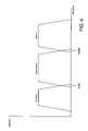
- FIG. 4shows a representative frequency allocation between cable service upstream/downstream signals and an overlaid local area network in accordance with the present invention.
- FIG. 5shows a network using direct broadcast satellite wiring with a coupler according to the present invention.
- amplifiers 222 and 224are part of the cable plant and provide a signal to the street and tap 220 .
- a frequency selective network interface device 210is located at the point of entry (POE) to the building LAN wiring. Alternatively, the frequency selective network interface can be located further inside the building, or at a point external to the building, for example at the street tap 220 .
- the network interface 210produces a reflection of upstream signals back into the LAN wiring so that terminal devices, such as LAN modem 270 , can receive a signal transmitted by another terminal device connected to the LAN wiring forming the network.
- the inventionintentionally introduces a reflection into the LAN wiring and exploits the reflected signal to provide communication path in a system that has high isolation between terminal devices due to splitters 230 , 231 , and 232 installed in the wiring.
- LAN modem 270provides modulation and demodulation of the waveform transmitted over the cable.
- LAN modem 270has an interface to communicate with a LAN device 280 , which is the source or destination of data transmitted over the LAN.
- LAN device 280can be, for example, a personal computer (PC).
- LAN device 282can be, for example, a modulator to produce a signal for driving a TV through a signal combiner.
- Existing devicessuch as TV 240 and cable modem 250 connected to PC 260 , use frequency bands distinct from the frequency band used by the LAN and therefore operate in a normal manner.
- the network interface devicecomprises a signal splitter 300 with an impedance mismatch 310 to create a reflected signal at one port, a frequency selective filter 320 coupled to the same port, and a frequency selective filter 330 coupled to a different port.
- the frequency selective filter 330provides isolation of the building LAN signal from the cable plant and passes standard cable service signals through with minimal disturbance. This filter would typically be a low pass filter.
- Network signals at high frequencies originating in the buildingpass through the splitter and are blocked by filter 330 .
- Filter 320passes the network signal and mismatched termination 310 reflects the signal back through the splitter 300 to the building wiring. The signal is distributed through the building wiring to all nodes.
- Impedance mismatch 310functions as a signal reflecting element.
- An impedance matched terminationwill have an impedance equal to the characteristic impedance of the transmission line, the splitter port, or filter port to which the termination is connected. For example, 75 Ohms is the characteristic impedance of a typical RG59 or RG6 system. A 75 Ohm termination will not produce a reflected signal. Terminations different from a matched termination will produce a reflected signal. The magnitude of the reflected signal will be a function of the termination impedance relative to the characteristic impedance.
- Impedance mismatch 310can be implemented in a number of ways.
- a short circuit of approximately 0 Ohms attached to the signal linewill produce a reflected wave of approximately equal magnitude to the incident wave with an inversion in the signal polarity.
- An open circuit, which is an impedance approaching infinite Ohms,will produce a reflected wave of approximately equal magnitude to the incident wave with the same signal polarity.
- Other impedances in between 0 and infinite Ohmsmay be used.
- the magnitude of the reflected signalwill vary in relation to the degree of mismatch.
- the reflection coefficientwill be (Z.sub.l ⁇ Z.sub.0)/(Z.sub.l+Z.sub.0), where Z.sub.l is the termination impedance and Z.sub.0 is the impedance of the port to which the termination is connected. See generally, Microwave Circuit Design Using Linear and Nonlinear Techniques by George D. Vendelin, et al, Wiley-Interscience Publication 1990, incorporated herein by reference.
- Impedance mismatch 310can also be implemented by introducing any impairment into an element, for example a cable, component, or connector, that changes the impedance of the element. Since impedance is determined by, among other factors, the cross sectional and longitudinal geometry of a transmission line, the impairment may be introduced by altering the geometry at one point or along a region of a transmission line. Impedance is also determined by the dielectric properties of the transmission line, so changing the dielectric at one point or in a region will also affect the impedance, creating a mismatch, and therefore a reflection.
- Impedance mismatch 310can also be implemented by altering the input or output impedance of the frequency selective filter used in the network interface device.
- the filterprovides the termination at the point of connection, and therefore a mismatch will produce a reflection.
- the level of reflection producedcan be adapted to the needs of the system, based on, for example, the number of splitters in the building wiring or in a branch of the wiring, or the signal loss known to exist in the building wiring or in a branch of the wiring.
- Splitters 300 and diplexer 302are well known devices. Filters 320 and 330 can be constructed using lumped element inductors, capacitors, and resistors, using microstrip and strip line techniques, or using other active and passive filter implementations. The selection of components to produce a filter with particular frequency characteristics is done using well known filter design techniques, including the use of computer aided design (CAD) tools.
- Splitter 300is designed to have a specific amount of coupling between the common port and the tap ports to create a desired level of signal reflection.
- the frequencies used by the LANcan be located above the standard cable use frequencies, which extend to 550 MHz or 750 MHz. Other frequency plans can be used, for example where a block of frequencies is available in the middle of the cable band.
- the filter cut-off frequenciesare selected according to the frequencies bands used.
- the network interface deviceuses a filter placed in between the POE and the customer premises.
- This filtercan be implemented as a passive filter using an inductor 350 , resistor 352 , and capacitor 354 .
- These filter componentscan be discrete components or formed using strip line or microstrip techniques.
- Inductor 350 resistor 352 , and capacitor 354determine the frequency response of the filter.
- the filteris a series notch filter that uses a parallel resonator. This filter presents an open condition to the series circuit at the resonance frequency, thereby reflecting the signal energy.
- the same filtercan be implemented using a series resonator connected in a shunt configuration.
- the filtercan be a lowpass, highpass, or bandpass filter. More complex filter topologies may be employed for pass band shaping and impedance matching outside the filter notch frequency.
- Filters with frequency characteristics determined primarily by reactive elementssuch as highpass, bandpass, lowpass, and bandstop filters implemented with inductors and capacitors, have a different impedance value in the pass band and stop band. This property may be exploited in the present invention where the filter has approximately matched impedance in the frequency of the signals to pass through the filter and a mismatch in the frequency range where reflection of signals is desired.
- filters employed in the present inventioninclude coaxial resonators, combline filters, interdigital filters, wave guide resonators, dielectric resonators, helical resonators, tubular bandpass filters, series resonators, parallel resonators, and other known filter techniques.
- the present inventionoperates by introducing a reflection in the LAN electrical wiring.
- a reflection anywhere in the wiringproduces a multipath signal in some or all wiring branches that creates inter-symbol interference (ISI).
- ISIinter-symbol interference
- the multipath signalhas a delay and amplitude difference relative to the main signal.
- a reflectionproduces ripples in the response of the channel, creating amplitude variations across the pass band.
- ISIis seen as an impairment to the shape of the digital signal pulses. ISI will degrade the bit error rate (BER) performance of the communication channel.
- BERbit error rate
- the effects of ISIcan be overcome by applying modulation techniques or receiver processing techniques.
- An adaptive equalizer in the terminal device receivercreates a filter response that restores a flat frequency response impaired by the multipath signal.
- the adaptive filtercan also be seen as a coherent summer of a main signal and reflected signals.
- DMTdiscrete multi-tone
- OFDMorthogonal frequency division multiplexing
- DS-SSspread spectrum modulation
- a DS-SS receivercan employ a rake receiver in which each reflected path is received, demodulated, and coherently combined to produce a single data stream.
- a variation of the DS-SS approachis to use code division multiplex (CDM), which uses data spreading of user data wherein a single user utilizes multiple spreading codes that are all transmitted on the same frequency band. User data is multiplexed between the several spreading codes to form multiple communication channels.
- CDM receiverde-spreads each code and combines the data, typically into a single data stream.
- a time domain equalizer (TEQ) or frequency domain equalizer (FEQ)can be used with any of the above described modulation techniques.
- the present inventioncould use a time division duplex (TDD) protocol for communications.
- TDDtime division duplex
- the receive and transmit dataare communicated during different time intervals, generally using the same frequency.
- the advantage of using TDDis that the transceiver design is simplified. Different users share a common frequency channel through the use of time division multiple access (TDMA).
- TDMAtime division multiple access
- each usertransmits during a different time interval. Users are assigned one or more slots of predetermined length in a framing structure that contains multiple slots. All users are synchronized by a beacon message broadcast on the network. The beacon message provides a common time reference to the users and can include other network management information.
- a signal coupling elementmay be introduced at one or more splitters in the building wiring. At each splitter junction, frequency selective coupling is created whereby the upstream signal at one splitter output port is coupled to other splitter output ports. Additionally, the LAN frequency band will couple through to the splitter input port.
- a conventional splittercan be replaced with a new splitter that has frequency selective inter-port coupling, or an additional device can be added to existing splitters to perform this function.
- a device added to a splitter in-line with the input connectionand would produce a reflection in a manner similar to the network interface device placed at the POE. In this embodiment the interface device would be configured so a portion of the signal is reflected and a portion is passed through.
- the main splittercan be constructed to introduce a reflecting circuit at each tap port along with some signal coupling between tap ports. This configuration allows some signal to reflect down the originating wiring branch to other devices in that branch and also couple to other wiring branches in the building.
- a satellite receiver outdoor unit 510typically comprises a dish antenna 520 , one or more low noise block-converters (LNB) 540 , and a multiport crosspoint switch 550 .
- the crosspoint switch 550allows connection of the outdoor unit 510 to more than one integrated receiver decoder (IRD) located inside the building.
- the LNB 540converts the signal transmitted by the satellite transponder, for example C band, Ku band or another frequency band, to a lower intermediate frequency (IF) suitable for transmission through coax.
- L band IF950 to 1450 MHZ
- RG6 coax cableis commonly used.
- the IRDdemodulates the IF signal from the LNB down to baseband, provides channel selection, decodes the digital data to produce a video signal, provides conditionally access, and generates an RF output to drive a television.
- frequency or directional selective couplingis added after the LNB, for example in or after the crosspoint switch.
- This deviceprovides coupling between coax cables connected to the outdoor unit.
- the network signalwould not use the same frequency band as the satellite signal.
- conventional splitters 562which have interport isolation, are used to couple the cable signals to a symmetric power summer 564 .
- Conventional splitter 562can be, for example, a 1.25 dB/6 dB splitter or some other ratio that provides an acceptable level of attenuation of the satellite signal wile providing an acceptable level of signal power for the network.
- the splittermay need to pass direct current (DC) to the LNB, which can be done by the inclusion of an inductor connecting the tap port to the common port.
- DCdirect current
- the L-band signal from the multiport switch 550passes through the splitter and is combined with the signal output of the summer 564 . Due to the directional nature of the splitter, which provides interport isolation, neither the summer signal nor the satellite signal passes through directly to the other tap port. A good quality splitter can achieve 20 dB or more of isolation between ports. Additional isolation between the satellite L-band signal and the network signals is achieved due to the non-overlapping frequency bands occupied by the respective signals.
- another implementation of the satellite system coupleruses frequency selective coupling to prevent interference with the L-band satellite signals.
- the frequency selective couplingfor example, comprises a low-pass filter to pass the band below L-band through the coupler.
- the couplingis provided by a symmetric combiner that distributes the energy from any port to the other ports.
- summer 564can be replaced with a directional splitter with an impedance mismatch connected to the common port. In this configuration, energy from each cable drop connected to an IRD is reflected back to the other cable drops.
- Multitone modulationuses a set of modulating carriers that are integer multiples of a common frequency and the symbol period is the inverse of the common frequency.
- Multitone modulationis also called discrete multitone (DMT) and orthogonal frequency division multiplexing (OFDM).
- OFDMutilizes quadrature phase shift keying (QPSK) and multi-level quadrature amplitude modulation (QAM) wherein each OFDM carrier can be modulated by an amplitude/phase varying signal.
- QPSKquadrature phase shift keying
- QAMmulti-level quadrature amplitude modulation
- To modulatedata bits are encoded into a number of m-ary PSK constellations, which then modulate the respective carriers. The carriers are summed together for transmission over the channel. Each carrier is independent and can be independently decoded in the receiver.
- OFDMprovides a mechanism to overcome the frequency selective channel impairments present in coaxial building wiring when employing a network interface device according to the present invention.
- QPSKis composed a sine and a cosine wave of identical frequency with phase modulation applied to each carrier independently.
- QAMis composed of sine and cosine waves with phase modulation and amplitude modulation. Both of these signals can be represented using complex numbers.
- the OFDM waveformis generated by applying an inverse discrete Fourier transform (IDFT) to a complex vector that results in a real valued time domain sequence. The time domain sequence is applied to an up converter to place the waveform at the proper RF frequency.
- IDFTinverse discrete Fourier transform
- Higher SNR channelscan support higher data capacity. Frequency bins occupying parts of the channel where the SNR is high can be used to transmit more bits. Each carrier may be modulated with a different order constellation, where higher SNR frequencies can bear a higher order constellation, and the resulting closer spacing of the constellation points. Frequencies with the lower SNR use lower order constellations such as QPSK.
- the power in individual frequency binscan be adjusted to compensate for insertion loss that varies as a function of frequency.
- the power level in regions of the channelcan be altered by scaling the complex valued vector for the bins where power adjustment is needed before applying the inverse Fourier transform. In order to avoid interference with certain bands in the RF spectrum, the power level of certain bins can be reduced to zero.
- An OFDM receiveruses a discrete Fourier transform (DFT) to convert the modulated signal back into data.
- DFTdiscrete Fourier transform
- the OFDM receiverreceives all the carriers at once and performs the transform on a block of data points.
- the frequency channels in OFDMmay be called frequency bins or simply bins.
- Various types of forward error correctioncan be applied to transmitted data blocks, such as Reed-Solomon and convolutional coding.
- Interleavingcan be applied to data blocks to increase the robustness of the error correction.
- De-interleaving and error correction codingare applied in the receiver to recover the transmitted data without errors.
- An OFDM receivermay also employ time domain equalization (TEQ), frequency domain equalization (FEQ), or both.
- TEQtime domain equalization
- FEQfrequency domain equalization
- the equalizersare adaptive.
- Equalizersmay be of the decision feedback (DFE) type or decision directed type such as least mean square (LMS) algorithm.
- OFDM system architectureis covered in ADSL/VDSL Principles by DR. Dennis J. Rauchmayer, Macmillan Technical Publishing, 1999 and DSL Simulation Techniques and Standards Development for Digital Subscriber Line Systems by Dr. Walter Y. Chen, Macmillan Technology Publishing, 1998.
Landscapes
- Engineering & Computer Science (AREA)
- Signal Processing (AREA)
- Multimedia (AREA)
- Computer Networks & Wireless Communication (AREA)
- Cable Transmission Systems, Equalization Of Radio And Reduction Of Echo (AREA)
Abstract
Description
(Z.sub.l−Z.sub.0)/(Z.sub.l+Z.sub.0),
where Z.sub.l is the termination impedance and Z.sub.0 is the impedance of the port to which the termination is connected. See generally,Microwave Circuit Design Using Linear and Nonlinear Techniquesby George D. Vendelin, et al, Wiley-Interscience Publication 1990, incorporated herein by reference.
Claims (17)
Priority Applications (7)
| Application Number | Priority Date | Filing Date | Title |
|---|---|---|---|
| US09/910,412US7594249B2 (en) | 2001-05-04 | 2001-07-21 | Network interface device and broadband local area network using coaxial cable |
| US10/215,609US7428238B2 (en) | 2001-07-21 | 2002-08-09 | Broadband network bridging various wiring channels |
| US10/889,975US7889759B2 (en) | 2001-05-04 | 2004-07-12 | Broadband cable network utilizing common bit-loading |
| US13/027,030US8588250B2 (en) | 2001-05-04 | 2011-02-14 | Broadband cable network utilizing common bit-loading |
| US14/082,544US9112803B2 (en) | 2001-05-04 | 2013-11-18 | Broadband cable network utilizing common bit-loading |
| US14/829,036US9860144B2 (en) | 2001-05-04 | 2015-08-18 | Broadband cable network utilizing common bit-loading |
| US15/860,400US20180131588A1 (en) | 2001-05-04 | 2018-01-02 | Broadband cable network utilizing common bit-loading |
Applications Claiming Priority (2)
| Application Number | Priority Date | Filing Date | Title |
|---|---|---|---|
| US28896701P | 2001-05-04 | 2001-05-04 | |
| US09/910,412US7594249B2 (en) | 2001-05-04 | 2001-07-21 | Network interface device and broadband local area network using coaxial cable |
Related Parent Applications (2)
| Application Number | Title | Priority Date | Filing Date |
|---|---|---|---|
| US10/322,834Continuation-In-PartUS7295518B1 (en) | 2001-05-04 | 2002-12-18 | Broadband network for coaxial cable using multi-carrier modulation |
| US13/027,030Continuation-In-PartUS8588250B2 (en) | 2001-05-04 | 2011-02-14 | Broadband cable network utilizing common bit-loading |
Related Child Applications (2)
| Application Number | Title | Priority Date | Filing Date |
|---|---|---|---|
| US77850504AContinuation | 2001-05-04 | 2004-02-13 | |
| US77850504AContinuation-In-Part | 2001-05-04 | 2004-02-13 |
Publications (2)
| Publication Number | Publication Date |
|---|---|
| US20020166124A1 US20020166124A1 (en) | 2002-11-07 |
| US7594249B2true US7594249B2 (en) | 2009-09-22 |
Family
ID=27396154
Family Applications (1)
| Application Number | Title | Priority Date | Filing Date |
|---|---|---|---|
| US09/910,412Expired - LifetimeUS7594249B2 (en) | 2001-05-04 | 2001-07-21 | Network interface device and broadband local area network using coaxial cable |
Country Status (1)
| Country | Link |
|---|---|
| US (1) | US7594249B2 (en) |
Cited By (7)
| Publication number | Priority date | Publication date | Assignee | Title |
|---|---|---|---|---|
| US20060233170A1 (en)* | 2001-05-17 | 2006-10-19 | Dan Avida | Stream-Oriented Interconnect for Networked Computer Storage |
| US20090296611A1 (en)* | 2001-08-30 | 2009-12-03 | Entropic Communications Inc. | Broadband Network for Coaxial Cable Using Multi-carrier Modulation |
| US20090303395A1 (en)* | 2005-05-02 | 2009-12-10 | Michael Anthony Pugel | Apparatus and method for distributing an input signal to multiple tuners |
| US20090302969A1 (en)* | 2005-08-10 | 2009-12-10 | Intellon Corporation | Communicating over coaxial cable networks |
| US20110249831A1 (en)* | 2010-04-13 | 2011-10-13 | Bellamy David C | Wireless microphone systems having improved immunity to rf interference |
| US20130178168A1 (en)* | 2012-01-10 | 2013-07-11 | Chunjie Duan | Multi-Band Matching Network for RF Power Amplifiers |
| US9054668B2 (en) | 2012-03-30 | 2015-06-09 | Broadcom Corporation | Broadband absorptive-loading filter |
Families Citing this family (121)
| Publication number | Priority date | Publication date | Assignee | Title |
|---|---|---|---|---|
| US6480510B1 (en) | 1998-07-28 | 2002-11-12 | Serconet Ltd. | Local area network of serial intelligent cells |
| US6956826B1 (en) | 1999-07-07 | 2005-10-18 | Serconet Ltd. | Local area network for distributing data communication, sensing and control signals |
| US6549616B1 (en) | 2000-03-20 | 2003-04-15 | Serconet Ltd. | Telephone outlet for implementing a local area network over telephone lines and a local area network using such outlets |
| US6842459B1 (en) | 2000-04-19 | 2005-01-11 | Serconet Ltd. | Network combining wired and non-wired segments |
| IL154695A0 (en) | 2000-08-30 | 2003-09-17 | Tiaris Inc | A home network system and method |
| US8724485B2 (en) | 2000-08-30 | 2014-05-13 | Broadcom Corporation | Home network system and method |
| US9094226B2 (en) | 2000-08-30 | 2015-07-28 | Broadcom Corporation | Home network system and method |
| US8127326B2 (en) | 2000-11-14 | 2012-02-28 | Claussen Paul J | Proximity detection using wireless connectivity in a communications system |
| CA2428946C (en) | 2000-11-14 | 2010-06-22 | Scientific-Atlanta, Inc. | Networked subscriber television distribution |
| US20020194605A1 (en)* | 2001-05-18 | 2002-12-19 | T.M.T. Third Millenium Technologies Ltd. | Cableran networking over coaxial cables |
| EP2234394A1 (en) | 2001-10-11 | 2010-09-29 | Mosaid Technologies Incorporated | Coupling device |
| US7274735B2 (en)* | 2002-02-28 | 2007-09-25 | Texas Instruments Incorporated | Constellation selection in a communication system |
| US7516470B2 (en) | 2002-08-02 | 2009-04-07 | Cisco Technology, Inc. | Locally-updated interactive program guide |
| US8181208B1 (en)* | 2002-08-07 | 2012-05-15 | Entropic Communications, Inc. | Media server and network for coaxial cable supporting legacy set top boxes |
| US20040177381A1 (en)* | 2002-09-05 | 2004-09-09 | Tiaris, Inc. | Home network system which supports legacy digital set top box devices |
| US7908625B2 (en) | 2002-10-02 | 2011-03-15 | Robertson Neil C | Networked multimedia system |
| US8046806B2 (en) | 2002-10-04 | 2011-10-25 | Wall William E | Multiroom point of deployment module |
| US7360235B2 (en)* | 2002-10-04 | 2008-04-15 | Scientific-Atlanta, Inc. | Systems and methods for operating a peripheral record/playback device in a networked multimedia system |
| US7545935B2 (en) | 2002-10-04 | 2009-06-09 | Scientific-Atlanta, Inc. | Networked multimedia overlay system |
| IL152824A (en) | 2002-11-13 | 2012-05-31 | Mosaid Technologies Inc | Addressable outlet and a network using same |
| US20050034159A1 (en)* | 2002-12-20 | 2005-02-10 | Texas Instruments Incorporated | Implementing a hybrid wireless and coaxial cable network |
| US8094640B2 (en) | 2003-01-15 | 2012-01-10 | Robertson Neil C | Full duplex wideband communications system for a local coaxial network |
| US7487532B2 (en)* | 2003-01-15 | 2009-02-03 | Cisco Technology, Inc. | Optimization of a full duplex wideband communications system |
| US7184472B2 (en)* | 2003-03-07 | 2007-02-27 | Texas Instruments Incorporated | Time domain equalizer and method |
| IL154921A (en) | 2003-03-13 | 2011-02-28 | Mosaid Technologies Inc | Telephone system having multiple distinct sources and accessories therefor |
| WO2004107113A2 (en)* | 2003-05-22 | 2004-12-09 | Coaxsys, Inc. | Networking methods and apparatus |
| IL157787A (en) | 2003-09-07 | 2010-12-30 | Mosaid Technologies Inc | Modular outlet for data communications network |
| US7437135B2 (en) | 2003-10-30 | 2008-10-14 | Interdigital Technology Corporation | Joint channel equalizer interference canceller advanced receiver |
| IL159838A0 (en) | 2004-01-13 | 2004-06-20 | Yehuda Binder | Information device |
| US7400692B2 (en) | 2004-01-14 | 2008-07-15 | Interdigital Technology Corporation | Telescoping window based equalization |
| IL160417A (en) | 2004-02-16 | 2011-04-28 | Mosaid Technologies Inc | Outlet add-on module |
| IL161869A (en) | 2004-05-06 | 2014-05-28 | Serconet Ltd | System and method for carrying a wireless based signal over wiring |
| US8763063B2 (en)* | 2004-06-01 | 2014-06-24 | Time Warner Cable Enterprises Llc | Controlled isolation splitter apparatus and methods |
| WO2006017466A2 (en)* | 2004-08-02 | 2006-02-16 | Coaxsys, Inc. | Computer networking techniques |
| US20060041912A1 (en)* | 2004-08-19 | 2006-02-23 | Kevin Kuhns | Method and apparatus for authorizing an additional set-top device in a satellite television network |
| US8631450B1 (en)* | 2004-12-02 | 2014-01-14 | Entropic Communications, Inc. | Broadband local area network |
| IL166445A (en)* | 2005-01-23 | 2011-07-31 | Mosaid Technologies Inc | Device and method for estimating the termination to a wired transmission-line based on determination of characteristic impedance |
| US8199684B2 (en)* | 2005-05-11 | 2012-06-12 | John Wai-Tsang Eng | Broadband local area full-service backbone network |
| US7876998B2 (en) | 2005-10-05 | 2011-01-25 | Wall William E | DVD playback over multi-room by copying to HDD |
| US20090154537A1 (en)* | 2005-10-12 | 2009-06-18 | Thomson Licensing Llc | Frequency Selection Cable Reflector |
| US7813451B2 (en) | 2006-01-11 | 2010-10-12 | Mobileaccess Networks Ltd. | Apparatus and method for frequency shifting of a wireless signal and systems using frequency shifting |
| US7675983B2 (en)* | 2006-04-14 | 2010-03-09 | Freescale Semiconductor, Inc. | Mitigation of DC distortion in OFDM receivers |
| BRPI0621683A2 (en)* | 2006-05-31 | 2011-12-20 | Thomson Licensing | local digital cable video distribution system |
| US7526248B2 (en)* | 2006-06-06 | 2009-04-28 | Nextwave Broadband, Inc. | Extended wireless communication system and method |
| US20080040758A1 (en)* | 2006-08-10 | 2008-02-14 | Todd Beetcher | Media system and method for purchasing, downloading and playing media content |
| US7720433B1 (en)* | 2006-09-29 | 2010-05-18 | The Directv Group, Inc. | Antenna hub configuration |
| US8090043B2 (en) | 2006-11-20 | 2012-01-03 | Broadcom Corporation | Apparatus and methods for compensating for signal imbalance in a receiver |
| US7697522B2 (en)* | 2006-11-20 | 2010-04-13 | Broadcom Corporation | Systems and methods for aggregation of packets for transmission through a communications network |
| US7782850B2 (en)* | 2006-11-20 | 2010-08-24 | Broadcom Corporation | MAC to PHY interface apparatus and methods for transmission of packets through a communications network |
| US7742495B2 (en) | 2006-11-20 | 2010-06-22 | Broadcom Corporation | System and method for retransmitting packets over a network of communication channels |
| US7953117B2 (en)* | 2007-04-10 | 2011-05-31 | Lantiq Deutschland Gmbh | Home networking system |
| US8345553B2 (en) | 2007-05-31 | 2013-01-01 | Broadcom Corporation | Apparatus and methods for reduction of transmission delay in a communication network |
| US8594133B2 (en) | 2007-10-22 | 2013-11-26 | Corning Mobileaccess Ltd. | Communication system using low bandwidth wires |
| US8299889B2 (en)* | 2007-12-07 | 2012-10-30 | Cisco Technology, Inc. | Home entertainment system providing presence and mobility via remote control authentication |
| US8175649B2 (en) | 2008-06-20 | 2012-05-08 | Corning Mobileaccess Ltd | Method and system for real time control of an active antenna over a distributed antenna system |
| US20090165070A1 (en)* | 2007-12-19 | 2009-06-25 | Broadcom Corporation | SYSTEMS AND METHODS FOR PROVIDING A MoCA COMPATABILITY STRATEGY |
| US20090265745A1 (en)* | 2008-04-17 | 2009-10-22 | Egan Jr John M | Reversible Faceplate Terminal Adapter Which Changes Signal Flow Direction |
| US8098770B2 (en) | 2008-05-06 | 2012-01-17 | Broadcom Corporation | Unbiased signal-to-noise ratio estimation for receiver having channel estimation error |
| US9363469B2 (en) | 2008-07-17 | 2016-06-07 | Ppc Broadband, Inc. | Passive-active terminal adapter and method having automatic return loss control |
| US9112717B2 (en) | 2008-07-31 | 2015-08-18 | Broadcom Corporation | Systems and methods for providing a MoCA power management strategy |
| US8286209B2 (en)* | 2008-10-21 | 2012-10-09 | John Mezzalingua Associates, Inc. | Multi-port entry adapter, hub and method for interfacing a CATV network and a MoCA network |
| US10154302B2 (en) | 2008-10-13 | 2018-12-11 | Ppc Broadband, Inc. | CATV entry adapter and method for distributing CATV and in-home entertainment signals |
| US8429695B2 (en)* | 2008-10-21 | 2013-04-23 | Ppc Broadband, Inc. | CATV entry adapter and method utilizing directional couplers for MoCA signal communication |
| US8356322B2 (en)* | 2009-09-21 | 2013-01-15 | John Mezzalingua Associates, Inc. | Passive multi-port entry adapter and method for preserving downstream CATV signal strength within in-home network |
| US9647851B2 (en) | 2008-10-13 | 2017-05-09 | Ppc Broadband, Inc. | Ingress noise inhibiting network interface device and method for cable television networks |
| US9351051B2 (en) | 2008-10-13 | 2016-05-24 | Ppc Broadband, Inc. | CATV entry adapter and method for distributing CATV and in-home entertainment signals |
| US8464301B2 (en) | 2008-10-16 | 2013-06-11 | Ppc Broadband, Inc. | Upstream bandwidth conditioning device between CATV distribution system and CATV user |
| US8213457B2 (en)* | 2009-10-09 | 2012-07-03 | John Mezzalingua Associates, Inc. | Upstream bandwidth conditioning device |
| US8516537B2 (en)* | 2009-10-09 | 2013-08-20 | Ppc Broadband, Inc. | Downstream bandwidth conditioning device |
| US8832767B2 (en)* | 2008-10-16 | 2014-09-09 | Ppc Broadband, Inc. | Dynamically configurable frequency band selection device between CATV distribution system and CATV user |
| US8001579B2 (en)* | 2008-10-16 | 2011-08-16 | John Mezzalingua Associates, Inc. | Downstream output level and/or output level tilt compensation device between CATV distribution system and CATV user |
| US8385219B2 (en)* | 2009-10-09 | 2013-02-26 | John Mezzalingua Associates, Inc. | Upstream bandwidth level measurement device |
| US11910052B2 (en) | 2008-10-21 | 2024-02-20 | Ppc Broadband, Inc. | Entry device for communicating external network signals and in-home network signals |
| US8510782B2 (en)* | 2008-10-21 | 2013-08-13 | Ppc Broadband, Inc. | CATV entry adapter and method for preventing interference with eMTA equipment from MoCA Signals |
| US8397271B2 (en) | 2008-12-18 | 2013-03-12 | Commscope, Inc. Of North Carolina | Power divider networks for cable television networks that include multimedia over coax bypass circuits and signal amplifiers that include such power divider networks |
| US8213309B2 (en) | 2008-12-22 | 2012-07-03 | Broadcom Corporation | Systems and methods for reducing latency and reservation request overhead in a communications network |
| US8254413B2 (en) | 2008-12-22 | 2012-08-28 | Broadcom Corporation | Systems and methods for physical layer (“PHY”) concatenation in a multimedia over coax alliance network |
| US8238227B2 (en) | 2008-12-22 | 2012-08-07 | Broadcom Corporation | Systems and methods for providing a MoCA improved performance for short burst packets |
| US8850509B2 (en)* | 2008-12-23 | 2014-09-30 | Cisco Technology, Inc. | Multiple frequency channel data distribution |
| GB2478256B (en)* | 2009-02-02 | 2014-09-17 | Technetix Group Ltd | Signal dividing device |
| WO2010089719A1 (en) | 2009-02-08 | 2010-08-12 | Mobileaccess Networks Ltd. | Communication system using cables carrying ethernet signals |
| US8181211B2 (en)* | 2009-03-30 | 2012-05-15 | John Mezzalingua Associates, Inc. | Total bandwidth conditioning device |
| US8141122B2 (en) | 2009-03-30 | 2012-03-20 | John Mezzalingua Associates, Inc. | RF terminate/permit system |
| US8179814B2 (en)* | 2009-03-30 | 2012-05-15 | John Mezzalingua Associates, Inc. | Automatic return path switching for a signal conditioning device |
| US8990881B2 (en)* | 2009-03-30 | 2015-03-24 | Ppc Broadband, Inc. | Upstream bandwidth conditioning device |
| US20100251322A1 (en)* | 2009-03-30 | 2010-09-30 | Raymond Palinkas | Upstream bandwidth conditioning device |
| US8584192B2 (en)* | 2009-03-30 | 2013-11-12 | Ppc Broadband, Inc. | Upstream bandwidth conditioning device |
| US8553547B2 (en) | 2009-03-30 | 2013-10-08 | Broadcom Corporation | Systems and methods for retransmitting packets over a network of communication channels |
| US8082570B2 (en)* | 2009-03-30 | 2011-12-20 | John Mezzalingua Associates, Inc. | Method and apparatus for a self-terminating signal path |
| US20100254278A1 (en) | 2009-04-07 | 2010-10-07 | Broadcom Corporation | Assessment in an information network |
| WO2010126472A1 (en)* | 2009-04-27 | 2010-11-04 | Thomson Licensing | Signal splitter for moca systems |
| US8730798B2 (en) | 2009-05-05 | 2014-05-20 | Broadcom Corporation | Transmitter channel throughput in an information network |
| US8098113B2 (en)* | 2009-05-29 | 2012-01-17 | John Mezzalingua Associates, Inc. | Self-terminating coaxial cable port |
| US8867355B2 (en) | 2009-07-14 | 2014-10-21 | Broadcom Corporation | MoCA multicast handling |
| US8942250B2 (en) | 2009-10-07 | 2015-01-27 | Broadcom Corporation | Systems and methods for providing service (“SRV”) node selection |
| US8274566B2 (en)* | 2009-10-09 | 2012-09-25 | John Mezzalingua Associates, Inc. | Modulation analyzer and level measurement device |
| US8350641B2 (en)* | 2010-01-26 | 2013-01-08 | John Mezzalingua Associates, Inc. | Band selective isolation bridge for splitter |
| US8487717B2 (en) | 2010-02-01 | 2013-07-16 | Ppc Broadband, Inc. | Multipath mitigation circuit for home network |
| US8611327B2 (en) | 2010-02-22 | 2013-12-17 | Broadcom Corporation | Method and apparatus for policing a QoS flow in a MoCA 2.0 network |
| US8514860B2 (en) | 2010-02-23 | 2013-08-20 | Broadcom Corporation | Systems and methods for implementing a high throughput mode for a MoCA device |
| US8479247B2 (en) | 2010-04-14 | 2013-07-02 | Ppc Broadband, Inc. | Upstream bandwidth conditioning device |
| US8561125B2 (en) | 2010-08-30 | 2013-10-15 | Ppc Broadband, Inc. | Home network frequency conditioning device and method |
| WO2012088350A2 (en) | 2010-12-21 | 2012-06-28 | John Mezzalingua Associates, Inc. | Method and apparatus for reducing isolation in a home network |
| SG191248A1 (en)* | 2011-01-17 | 2013-07-31 | Ericsson Telefon Ab L M | An active antenna arrangement for transmitting precoded signals in a communication system, base station, methods and computer programs |
| US20130201316A1 (en) | 2012-01-09 | 2013-08-08 | May Patents Ltd. | System and method for server based control |
| EP2829152A2 (en) | 2012-03-23 | 2015-01-28 | Corning Optical Communications Wireless Ltd. | Radio-frequency integrated circuit (rfic) chip(s) for providing distributed antenna system functionalities, and related components, systems, and methods |
| US9264012B2 (en) | 2012-06-25 | 2016-02-16 | Ppc Broadband, Inc. | Radio frequency signal splitter |
| US9356796B2 (en)* | 2013-04-23 | 2016-05-31 | Times Fiber Communications, Inc. | MoCA gateway splitter |
| US9184960B1 (en) | 2014-09-25 | 2015-11-10 | Corning Optical Communications Wireless Ltd | Frequency shifting a communications signal(s) in a multi-frequency distributed antenna system (DAS) to avoid or reduce frequency interference |
| KR102234495B1 (en)* | 2015-01-26 | 2021-03-31 | 한국전자통신연구원 | Method for cancellating interference in satellite communications system and satellite communications system |
| CA3028756A1 (en) | 2016-06-30 | 2018-01-04 | Ppc Broadband, Inc. | Passive enhanced moca entry device |
| US9888278B2 (en)* | 2016-07-07 | 2018-02-06 | Telefonaktiebolaget Lm Ericsson (Publ) | Bandwidth and ABR video QoE management based on OTT video providers and devices |
| US10911804B2 (en)* | 2016-08-17 | 2021-02-02 | Nec Corporation | Bitrate instruction device, bitrate instruction method, and non-transitory recording medium |
| CN109792546B (en)* | 2016-09-30 | 2022-01-04 | 英国电讯有限公司 | Method for transmitting video content from server to client device |
| CN109792545B (en) | 2016-09-30 | 2021-12-07 | 英国电讯有限公司 | Method for transmitting video content from server to client device |
| WO2019143613A2 (en) | 2018-01-19 | 2019-07-25 | Ppc Broadband, Inc. | Systems and methods for extending an in-home splitter network |
| CN113132765A (en)* | 2020-01-16 | 2021-07-16 | 北京达佳互联信息技术有限公司 | Code rate decision model training method and device, electronic equipment and storage medium |
| WO2022037798A1 (en)* | 2020-08-18 | 2022-02-24 | Telefonaktiebolaget Lm Ericsson (Publ) | Estimating video resolution delivered by an encrypted video stream |
| US11711225B2 (en)* | 2020-10-13 | 2023-07-25 | Marvell Asia Pte Ltd | Reduction of power-over-data-lines (PODL) filter parasitics for multi-gigabit ethernet |
| KR102734487B1 (en)* | 2021-12-21 | 2024-11-26 | 한국전자통신연구원 | Method and apparatus for processing adaptive multiview streaming |
| JP2025037690A (en)* | 2023-09-06 | 2025-03-18 | 富士通株式会社 | Estimation method, estimation program, and communication processing device |
Citations (21)
| Publication number | Priority date | Publication date | Assignee | Title |
|---|---|---|---|---|
| US4222066A (en)* | 1977-12-22 | 1980-09-09 | North American Philips Corporation | CATV Subscription service control device and attenuator therefor |
| US4633309A (en)* | 1985-05-06 | 1986-12-30 | Oak Industries Inc. | Cable television master/slave decoder control |
| US4864613A (en)* | 1986-11-10 | 1989-09-05 | General Instrument Corporation | Broadband converter/descrambler interface for cable TV |
| US4933745A (en)* | 1988-11-25 | 1990-06-12 | Raytheon Company | Microwave device package |
| US5726701A (en)* | 1995-04-20 | 1998-03-10 | Intel Corporation | Method and apparatus for stimulating the responses of a physically-distributed audience |
| US5809421A (en)* | 1996-01-02 | 1998-09-15 | Motorola, Inc. | Method for locating variable control channels by a mobile station in a radiotelephone system |
| US5969582A (en)* | 1997-07-03 | 1999-10-19 | Ericsson Inc. | Impedance matching circuit for power amplifier |
| US6061820A (en)* | 1994-12-28 | 2000-05-09 | Kabushiki Kaisha Toshiba | Scheme for error control on ATM adaptation layer in ATM networks |
| US6091932A (en)* | 1995-05-20 | 2000-07-18 | Regiocom Gmbh | Bidirectional point to multipoint network using multicarrier modulation |
| US6144399A (en)* | 1999-03-25 | 2000-11-07 | Mediaone Group, Inc. | Passive system used to merge telephone and broadband signals onto one coaxial cable |
| US6226322B1 (en)* | 1998-03-30 | 2001-05-01 | Texas Instruments Incorporated | Analog receive equalizer for digital-subscriber-line communications system |
| US20010021998A1 (en)* | 1999-05-26 | 2001-09-13 | Neal Margulis | Apparatus and method for effectively implementing a wireless television system |
| US6381745B1 (en)* | 1998-05-21 | 2002-04-30 | Avaya Technology Corp. | Signal distribution system |
| US6396886B1 (en)* | 1999-02-12 | 2002-05-28 | Nec Usa, Inc. | DMT time-domain equalizer algorithm |
| US20020069417A1 (en)* | 2000-08-30 | 2002-06-06 | Avi Kliger | Home network system and method |
| US20020088005A1 (en)* | 2000-04-12 | 2002-07-04 | Yiyan Wu | Method and system for tiered digital television terrestrial broadcasting services using multi-bit-stream frequency interleaved OFDM |
| US20020145968A1 (en)* | 2001-02-28 | 2002-10-10 | Hongliang Zhang | Transmit power control for an OFDM-based wireless communication system |
| US6622304B1 (en)* | 1996-09-09 | 2003-09-16 | Thomas W. Carhart | Interface system for computing apparatus and communications stations |
| US6771706B2 (en)* | 2001-03-23 | 2004-08-03 | Qualcomm Incorporated | Method and apparatus for utilizing channel state information in a wireless communication system |
| US6778601B2 (en)* | 2000-02-17 | 2004-08-17 | Alpine Electronics, Inc. | Adaptive audio equalizer apparatus and method of determining filter coefficient |
| US6788707B1 (en)* | 1999-08-31 | 2004-09-07 | Broadcom Corporation | Method for the suppression and expansion of packet header information in cable modem and cable modem termination system devices |
Family Cites Families (1)
| Publication number | Priority date | Publication date | Assignee | Title |
|---|---|---|---|---|
| US7075389B1 (en)* | 2000-05-25 | 2006-07-11 | Motorola Inc. | Method and apparatus for achieving broadband matching of narrow-band resonator filter impedances to loads and sources |
- 2001
- 2001-07-21USUS09/910,412patent/US7594249B2/ennot_activeExpired - Lifetime
Patent Citations (22)
| Publication number | Priority date | Publication date | Assignee | Title |
|---|---|---|---|---|
| US4222066A (en)* | 1977-12-22 | 1980-09-09 | North American Philips Corporation | CATV Subscription service control device and attenuator therefor |
| US4633309A (en)* | 1985-05-06 | 1986-12-30 | Oak Industries Inc. | Cable television master/slave decoder control |
| US4864613A (en)* | 1986-11-10 | 1989-09-05 | General Instrument Corporation | Broadband converter/descrambler interface for cable TV |
| US4933745A (en)* | 1988-11-25 | 1990-06-12 | Raytheon Company | Microwave device package |
| US6061820A (en)* | 1994-12-28 | 2000-05-09 | Kabushiki Kaisha Toshiba | Scheme for error control on ATM adaptation layer in ATM networks |
| US5726701A (en)* | 1995-04-20 | 1998-03-10 | Intel Corporation | Method and apparatus for stimulating the responses of a physically-distributed audience |
| US6091932A (en)* | 1995-05-20 | 2000-07-18 | Regiocom Gmbh | Bidirectional point to multipoint network using multicarrier modulation |
| US5809421A (en)* | 1996-01-02 | 1998-09-15 | Motorola, Inc. | Method for locating variable control channels by a mobile station in a radiotelephone system |
| US6622304B1 (en)* | 1996-09-09 | 2003-09-16 | Thomas W. Carhart | Interface system for computing apparatus and communications stations |
| US5969582A (en)* | 1997-07-03 | 1999-10-19 | Ericsson Inc. | Impedance matching circuit for power amplifier |
| US6226322B1 (en)* | 1998-03-30 | 2001-05-01 | Texas Instruments Incorporated | Analog receive equalizer for digital-subscriber-line communications system |
| US6381745B1 (en)* | 1998-05-21 | 2002-04-30 | Avaya Technology Corp. | Signal distribution system |
| US6396886B1 (en)* | 1999-02-12 | 2002-05-28 | Nec Usa, Inc. | DMT time-domain equalizer algorithm |
| US6144399A (en)* | 1999-03-25 | 2000-11-07 | Mediaone Group, Inc. | Passive system used to merge telephone and broadband signals onto one coaxial cable |
| US20010021998A1 (en)* | 1999-05-26 | 2001-09-13 | Neal Margulis | Apparatus and method for effectively implementing a wireless television system |
| US6788707B1 (en)* | 1999-08-31 | 2004-09-07 | Broadcom Corporation | Method for the suppression and expansion of packet header information in cable modem and cable modem termination system devices |
| US6778601B2 (en)* | 2000-02-17 | 2004-08-17 | Alpine Electronics, Inc. | Adaptive audio equalizer apparatus and method of determining filter coefficient |
| US20020088005A1 (en)* | 2000-04-12 | 2002-07-04 | Yiyan Wu | Method and system for tiered digital television terrestrial broadcasting services using multi-bit-stream frequency interleaved OFDM |
| US20020069417A1 (en)* | 2000-08-30 | 2002-06-06 | Avi Kliger | Home network system and method |
| US20020145968A1 (en)* | 2001-02-28 | 2002-10-10 | Hongliang Zhang | Transmit power control for an OFDM-based wireless communication system |
| US7151740B2 (en)* | 2001-02-28 | 2006-12-19 | Cingular Wireless Ii, Llc | Transmit power control for an OFDM-based wireless communication system |
| US6771706B2 (en)* | 2001-03-23 | 2004-08-03 | Qualcomm Incorporated | Method and apparatus for utilizing channel state information in a wireless communication system |
Cited By (11)
| Publication number | Priority date | Publication date | Assignee | Title |
|---|---|---|---|---|
| US20060233170A1 (en)* | 2001-05-17 | 2006-10-19 | Dan Avida | Stream-Oriented Interconnect for Networked Computer Storage |
| US7944936B2 (en)* | 2001-05-17 | 2011-05-17 | Netapp, Inc. | Stream-oriented interconnect for networked computer storage |
| US20090296611A1 (en)* | 2001-08-30 | 2009-12-03 | Entropic Communications Inc. | Broadband Network for Coaxial Cable Using Multi-carrier Modulation |
| US20110194636A1 (en)* | 2001-08-30 | 2011-08-11 | Entropic Communications, Inc. | Broadband Network for Coaxial Cable Using Multi-carrier Modulation |
| US8411565B2 (en)* | 2001-08-30 | 2013-04-02 | Entropic Communications, Inc. | Broadband network for coaxial cable using multi-carrier modulation |
| US20090303395A1 (en)* | 2005-05-02 | 2009-12-10 | Michael Anthony Pugel | Apparatus and method for distributing an input signal to multiple tuners |
| US20090302969A1 (en)* | 2005-08-10 | 2009-12-10 | Intellon Corporation | Communicating over coaxial cable networks |
| US8154361B2 (en)* | 2005-08-10 | 2012-04-10 | Qualcomm Atheros, Inc. | Communicating over coaxial cable networks |
| US20110249831A1 (en)* | 2010-04-13 | 2011-10-13 | Bellamy David C | Wireless microphone systems having improved immunity to rf interference |
| US20130178168A1 (en)* | 2012-01-10 | 2013-07-11 | Chunjie Duan | Multi-Band Matching Network for RF Power Amplifiers |
| US9054668B2 (en) | 2012-03-30 | 2015-06-09 | Broadcom Corporation | Broadband absorptive-loading filter |
Also Published As
| Publication number | Publication date |
|---|---|
| US20020166124A1 (en) | 2002-11-07 |
Similar Documents
| Publication | Publication Date | Title |
|---|---|---|
| US7594249B2 (en) | Network interface device and broadband local area network using coaxial cable | |
| US8411565B2 (en) | Broadband network for coaxial cable using multi-carrier modulation | |
| US8154361B2 (en) | Communicating over coaxial cable networks | |
| US9860144B2 (en) | Broadband cable network utilizing common bit-loading | |
| KR101284380B1 (en) | Bridging coaxial cable networks | |
| US9647722B2 (en) | Adaptive line equalizer for improving data communication over less than perfect power lines or transmission lines | |
| US6414952B2 (en) | Virtual gateway system and method | |
| US20020109585A1 (en) | Apparatus, method and system for range extension of a data communication signal on a high voltage cable | |
| US6731678B1 (en) | System and method for extending the operating range and/or increasing the bandwidth of a communication link | |
| WO2002093758A2 (en) | Apparatus for transporting home networking frame-based communications signals over coaxial cables | |
| WO2013090255A1 (en) | 10 gbps coaxial cable networking system | |
| US7020186B2 (en) | Multi-mode bi-directional communications device including a diplexer having switchable low pass filters | |
| Lawrence et al. | Broadband access to the home on copper | |
| Chen et al. | Coaxial cable distribution plant performance simulation for interactive multimedia TV | |
| EP1675288A2 (en) | An arrangement for the transmission of a data signal in a cable television network | |
| Sjöberg | A vdsl tutorial | |
| Carangi et al. | Coaxial cable distribution plant performance simulation | |
| WO2002033968A1 (en) | System and method for expanding the operative bandwidth of a cable television communication system | |
| Jacobsen et al. | High-performance multimedia transmission on the cable television network | |
| Hazmi et al. | DVB-T signal in cable TV network: advantages and limitations | |
| US20030035073A1 (en) | Multimode downstream signal processing in a bi-directional communications device | |
| Cherubini | Signal Processing for Network Access Technologies: An Overview | |
| YAO | DATA TRANSMISSIONS THROUGH HFC RETURN CHANNELS |
Legal Events
| Date | Code | Title | Description |
|---|---|---|---|
| AS | Assignment | Owner name:ENTROPIC COMMUNICATIONS INC., CALIFORNIA Free format text:ASSIGNMENT OF ASSIGNORS INTEREST;ASSIGNORS:GURANTZ, ITZHAK;ELWARDANI, LADD;MONK, ANTON;AND OTHERS;REEL/FRAME:012499/0136;SIGNING DATES FROM 20010627 TO 20010718 | |
| AS | Assignment | Owner name:SILICON VALLEY BANK, CALIFORNIA Free format text:SECURITY INTEREST;ASSIGNOR:ENTROPIC COMMUNICATIONS, INC.;REEL/FRAME:013016/0075 Effective date:20020306 | |
| AS | Assignment | Owner name:ENTROPIC COMMUNICATIONS, INC., CALIFORNIA Free format text:RELEASE;ASSIGNOR:SILICON VALLEY BANK;REEL/FRAME:014072/0754 Effective date:20030512 | |
| STCF | Information on status: patent grant | Free format text:PATENTED CASE | |
| FPAY | Fee payment | Year of fee payment:4 | |
| AS | Assignment | Owner name:ENTROPIC COMMUNICATIONS, INC., CALIFORNIA Free format text:MERGER AND CHANGE OF NAME;ASSIGNORS:EXCALIBUR ACQUISITION CORPORATION;ENTROPIC COMMUNICATIONS, INC.;ENTROPIC COMMUNICATIONS, INC.;REEL/FRAME:035706/0267 Effective date:20150430 | |
| AS | Assignment | Owner name:ENTROPIC COMMUNICATIONS, LLC, CALIFORNIA Free format text:MERGER AND CHANGE OF NAME;ASSIGNORS:ENTROPIC COMMUNICATIONS, INC.;EXCALIBUR SUBSIDIARY, LLC;ENTROPIC COMMUNICATIONS, LLC;REEL/FRAME:035717/0628 Effective date:20150430 | |
| FPAY | Fee payment | Year of fee payment:8 | |
| AS | Assignment | Owner name:JPMORGAN CHASE BANK, N.A., AS COLLATERAL AGENT, IL Free format text:SECURITY AGREEMENT;ASSIGNORS:MAXLINEAR, INC.;ENTROPIC COMMUNICATIONS, LLC (F/K/A ENTROPIC COMMUNICATIONS, INC.);EXAR CORPORATION;REEL/FRAME:042453/0001 Effective date:20170512 Owner name:JPMORGAN CHASE BANK, N.A., AS COLLATERAL AGENT, ILLINOIS Free format text:SECURITY AGREEMENT;ASSIGNORS:MAXLINEAR, INC.;ENTROPIC COMMUNICATIONS, LLC (F/K/A ENTROPIC COMMUNICATIONS, INC.);EXAR CORPORATION;REEL/FRAME:042453/0001 Effective date:20170512 | |
| AS | Assignment | Owner name:MUFG UNION BANK, N.A., CALIFORNIA Free format text:SUCCESSION OF AGENCY (REEL 042453 / FRAME 0001);ASSIGNOR:JPMORGAN CHASE BANK, N.A.;REEL/FRAME:053115/0842 Effective date:20200701 | |
| AS | Assignment | Owner name:MAXLINEAR COMMUNICATIONS LLC, CALIFORNIA Free format text:CHANGE OF NAME;ASSIGNOR:ENTROPIC COMMUNICATONS LLC;REEL/FRAME:055776/0482 Effective date:20180213 | |
| AS | Assignment | Owner name:MAXLINEAR, INC., CALIFORNIA Free format text:RELEASE BY SECURED PARTY;ASSIGNOR:MUFG UNION BANK, N.A.;REEL/FRAME:055779/0001 Effective date:20210331 Owner name:MAXLINEAR COMMUNICATIONS LLC, CALIFORNIA Free format text:RELEASE BY SECURED PARTY;ASSIGNOR:MUFG UNION BANK, N.A.;REEL/FRAME:055779/0001 Effective date:20210331 | |
| AS | Assignment | Owner name:ENTROPIC COMMUNICATIONS, LLC, NEW YORK Free format text:ASSIGNMENT OF ASSIGNORS INTEREST;ASSIGNOR:MAXLINEAR COMMUNICATIONS LLC;REEL/FRAME:055899/0291 Effective date:20210331 | |
| FEPP | Fee payment procedure | Free format text:MAINTENANCE FEE REMINDER MAILED (ORIGINAL EVENT CODE: REM.); ENTITY STATUS OF PATENT OWNER: LARGE ENTITY | |
| FEPP | Fee payment procedure | Free format text:11.5 YR SURCHARGE- LATE PMT W/IN 6 MO, LARGE ENTITY (ORIGINAL EVENT CODE: M1556); ENTITY STATUS OF PATENT OWNER: LARGE ENTITY | |
| MAFP | Maintenance fee payment | Free format text:PAYMENT OF MAINTENANCE FEE, 12TH YEAR, LARGE ENTITY (ORIGINAL EVENT CODE: M1553); ENTITY STATUS OF PATENT OWNER: LARGE ENTITY Year of fee payment:12 | |
| AS | Assignment | Owner name:MAXLINEAR, INC., CALIFORNIA Free format text:RELEASE BY SECURED PARTY;ASSIGNOR:MUFG UNION BANK, N.A.;REEL/FRAME:056656/0204 Effective date:20210623 Owner name:EXAR CORPORATION, CALIFORNIA Free format text:RELEASE BY SECURED PARTY;ASSIGNOR:MUFG UNION BANK, N.A.;REEL/FRAME:056656/0204 Effective date:20210623 Owner name:MAXLINEAR COMMUNICATIONS LLC, CALIFORNIA Free format text:RELEASE BY SECURED PARTY;ASSIGNOR:MUFG UNION BANK, N.A.;REEL/FRAME:056656/0204 Effective date:20210623 | |
| RR | Request for reexamination filed | Effective date:20230911 | |
| IPR | Aia trial proceeding filed before the patent and appeal board: inter partes review | Free format text:TRIAL NO: IPR2024-00373 Opponent name:DISH NETWORK L.L.C., DISH NETWORK SERVICE L.L.C., DISH NETWORK CORPORATION, AND DISH NETWORK CALIFORNIA SERVICE CORPORATION Effective date:20240116 | |
| CONR | Reexamination decision confirms claims | Kind code of ref document:C1 Free format text:REEXAMINATION CERTIFICATE Filing date:20230911 Effective date:20240715 | |
| IPR | Aia trial proceeding filed before the patent and appeal board: inter partes review | Free format text:TRIAL NO: IPR2024-01060 Opponent name:DIRECTV, LLC,DIRECTV HOLDINGS LLC,THE DIRECTV GROUP, INC., ANDDIRECTV GROUP HOLDINGS, LLC Effective date:20240701 |