US7594075B2 - Metadata for a grid based data storage system - Google Patents
Metadata for a grid based data storage systemDownload PDFInfo
- Publication number
- US7594075B2 US7594075B2US10/969,580US96958004AUS7594075B2US 7594075 B2US7594075 B2US 7594075B2US 96958004 AUS96958004 AUS 96958004AUS 7594075 B2US7594075 B2US 7594075B2
- Authority
- US
- United States
- Prior art keywords
- storage
- sheet
- data
- storage unit
- allocation
- Prior art date
- Legal status (The legal status is an assumption and is not a legal conclusion. Google has not performed a legal analysis and makes no representation as to the accuracy of the status listed.)
- Active, expires
Links
Images


Classifications
- H—ELECTRICITY
- H04—ELECTRIC COMMUNICATION TECHNIQUE
- H04L—TRANSMISSION OF DIGITAL INFORMATION, e.g. TELEGRAPHIC COMMUNICATION
- H04L67/00—Network arrangements or protocols for supporting network services or applications
- H04L67/01—Protocols
- H04L67/10—Protocols in which an application is distributed across nodes in the network
- H04L67/1097—Protocols in which an application is distributed across nodes in the network for distributed storage of data in networks, e.g. transport arrangements for network file system [NFS], storage area networks [SAN] or network attached storage [NAS]
- G—PHYSICS
- G06—COMPUTING OR CALCULATING; COUNTING
- G06F—ELECTRIC DIGITAL DATA PROCESSING
- G06F11/00—Error detection; Error correction; Monitoring
- G06F11/07—Responding to the occurrence of a fault, e.g. fault tolerance
- G06F11/08—Error detection or correction by redundancy in data representation, e.g. by using checking codes
- G06F11/10—Adding special bits or symbols to the coded information, e.g. parity check, casting out 9's or 11's
- G06F11/1076—Parity data used in redundant arrays of independent storages, e.g. in RAID systems
- G—PHYSICS
- G06—COMPUTING OR CALCULATING; COUNTING
- G06F—ELECTRIC DIGITAL DATA PROCESSING
- G06F2211/00—Indexing scheme relating to details of data-processing equipment not covered by groups G06F3/00 - G06F13/00
- G06F2211/10—Indexing scheme relating to G06F11/10
- G06F2211/1002—Indexing scheme relating to G06F11/1076
- G06F2211/1028—Distributed, i.e. distributed RAID systems with parity
Definitions
- the embodiments of the present inventionrelate generally to computer systems storage capacity and more particularly, but without limitation, to metadata architecture describing the configuration of allocated memory in the storage capacity.
- Computer systemscomprise input devices, output devices, one or more central processing units (CPUs), and storage capacity.
- the storage capacitytakes form in many data storage devices, such as semiconductor memory, disc drives, and optical drives.
- An operating systemprovides an application environment and a file system that allocates or de-allocates storage capacity as files are created, modified, or deleted.
- Data storage systemssuch as servers also employ a file system for allocating storage capacity that is accessed through a network or other connection.
- Servers and storage arrayssupport data storage formats such as a redundant array of independent drives (RAID) that distributes stored information across a plurality of data storage devices.
- RAIDredundant array of independent drives
- Data structures containing information describing the manner in which the data are mapped to memoryis termed metadata. As files are created, modified, or deleted, metadata is updated to reflect the allocation or de-allocation (sometimes referred to collectively as “allocation”) of storage capacity.
- the structure of metadatacan significantly impact storage system performance. As the storage capacity of a system grows, the amount of metadata employed to manage the system also grows. As data structures using metadata become larger, the amount of time needed to parse information from the structures and to update these structures becomes significant.
- the embodiments of the present inventionare generally directed to an apparatus and associated method for describing computer system configuration information.
- Some embodiments of the present inventionare directed to metadata for a data storage system employing a grid-based storage capacity wherein each grid defines a storage unit in terms of a plurality of storage domains along one axis against one or more rows of a plurality of storage stripes along another axis, and wherein a grid grouping of two or more grids defines a sheet of data storage capacity.
- the metadatacomprises identification information stored in a memory space characterizing an allocation status of the sheets in the storage system.
- a method for allocating memory for the grid-based data storage systemcomprising determining whether the allocation is associated with an existing logical device. If the determining step is associated with an existing logical device, then a logical device allocation map and a sheet allocation table are accessed to allocate a selected storage unit. Otherwise, a sheet allocation descriptor and a sheet allocation map are accessed to allocate a selected storage unit.
- a method for transferring data for the grid-based data storage systemcomprising accessing a logical device allocation map and a drive organization table to transfer data to or from a selected storage unit.
- FIG. 1is a diagrammatical depiction of exemplary operating systems in which various embodiments of the present invention can be employed.
- FIG. 2is a top level functional block depiction of a computer-based system characterized as a wide-area network utilizing mass storage.
- FIG. 3provides a functional block diagram illustrating a selected one of the controllers of FIG. 2 .
- FIG. 4is a diagrammatical depiction of a data storage device memory.
- FIG. 5is a diagrammatical depiction of a grid-based data storage capacity.
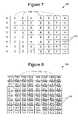
- FIG. 6is a diagrammatical depiction of a sheet organization table for data storage sheets employing ten drives in the grid.
- FIG. 8is a diagrammatical depiction of a user data grid.
- FIG. 10is a diagrammatical depiction of a user/parity grid adapted for RAID 5 and RAID 6 levels.
- FIG. 11is a diagrammatical depiction of grid utilization for various RAID levels.
- FIG. 12is a diagrammatical depiction of data sheet capacity hierarchy.
- FIG. 14is a diagrammatical depiction of a logical device allocation map.
- FIG. 15is a diagrammatical depiction of a link listed logical device allocation map.
- FIG. 16is a diagrammatical depiction of a reliable storage unit allocation descriptor array.
- FIG. 17is a diagrammatical depiction of a sheet allocation table.
- FIG. 18is a diagrammatical depiction of a drive organization table.
- FIG. 19is a process flowchart illustrating steps for ALLOCATING STORAGE CAPACITY in accordance with embodiments of the present invention.
- FIG. 20is a process flowchart illustrating steps for TRANSFERRING DATA in accordance with embodiments of the present invention.
- embodiments of the present inventioncan be used in a system 100 that includes at least two data storage devices 101 and one controller.
- Embodiments of the present inventioncan be employed in simple systems having little or no fault tolerance redundancy to highly redundant systems having no single point of failure.
- FIG. 2shows a computer-based system 100 C characterized as a wide area network (WAN) utilizing mass storage.
- WANwide area network
- the system 100 Cincludes a number of host computers 102 , respectively identified as hosts A, B, and C.
- the host computers 102interact with each other as well as with a pair of data storage arrays 104 (denoted A and B, respectively) via a fabric 106 .
- the fabric 106is preferably characterized as fibre-channel based switching network, although other configurations can be utilized as well including the Internet.
- Each array 104includes a pair of controllers 108 (denoted A 1 , A 2 and B 1 , B 2 ) and a set of data storage devices 101 preferably characterized as disc drives operated as a RAID.
- the controllers 108 and data storage devices 101preferably utilize a fault tolerant arrangement so that the various controllers 108 utilize parallel, redundant links and at least some of the user data stored by the system 100 C is stored in a redundant format within at least one set of the data storage devices 101 .
- FIG. 3illustrates a selected one of the controllers 108 in greater detail.
- the controller 108can be embodied in a single integrated circuit, or distributed among a number of discrete circuits as desired.
- a main processor 112preferably characterized as a programmable, computer processor, provides control in accordance with programming steps and processing data preferably stored in non-volatile memory 114 (such as flash memory or similar) and in dynamic random access memory (DRAM) 116 .
- non-volatile memory 114such as flash memory or similar
- DRAMdynamic random access memory
- a fabric interface (I/F) circuit 118communicates with the other controllers 108 and the host computers 102 via the fabric 106 , and a device I/F circuit 120 communicates with the storage devices 101 .
- the I/F circuits 118 , 122 and a path controller 120form a communication path to pass commands and data between the storage array 104 and the host 102 , such as by employing the cache memory 124 .
- the path controller 120 and the I/F circuits 118 , 122can be unitarily constructed.
- the data storage capacity of an array 104is organized into logical units (“LUNs”) that can be written to and read from the array 104 .
- System configuration informationdefines the relationship between user data, including any associated parity and mirror data, with the respective storage locations.
- the system configurationfurthermore identifies the relationship between blocks of storage capacity allocated to user data and the memory storage locations, such as logical block addresses (LBA).
- LBAlogical block addresses
- the system configurationcan furthermore include virtualization by defining virtual block addresses that are mapped to logical block addresses.
- System configuration informationis changed when storage capacity is allocated, such as when saving new files or enlarging existing files, or after storage capacity is deallocated, such as when deleting files or reducing the size of existing files.
- System metadatadefines file allocation information and other data structures that support allocation processes.
- FIG. 4is a diagrammatical representation of an overview in terms of a storage map 130 showing a portion of the storage capacity contained in the data storage device 101 ( FIG. 1 ).
- stripeis used in a generic sense, and not only in terms of a RAID stripe as defined by the RAID Advisory Board (RAB).
- the storage map 130depicts stripes 132 (sometimes referred to herein as “sub partitions” 132 ), each containing a predefined portion of the storage capacity.
- the amount of storage capacity in stripes 132can reflect the type of storage applications of the system.
- Each stripe 132starts at an LBA.
- stripe 1begins at LBA 134
- stripe 2begins at LBA 136
- stripe 3begins at LBA 138
- a plurality of other stripes 132can be defined up to Stripe N that begins at LBA 140 .
- the end of one stripe 132is immediately adjacent the next stripe 132 so that there is no unused storage capacity between adjacent stripes 132 .
- FIG. 5depicts a grid 150 based storage capacity arrangement for the system 100 C.
- Each column in the grid 150corresponds to one data storage device 101 , or storage domain, and each row in the grid 150 corresponds to a plurality of stripes 132 , with one stripe 132 in each data storage device drive 101 .
- Stripes 132 in one rowcan start at the same or at different LBAs.
- Spare capacityis distributed across sub-partitions of data storage device 101 partitions. Accordingly, stripes 132 can be allocated to store data or can be spares. Stripes 132 containing data store such things as user information, mirror data, or parity data. Spare stripes 132 can be configured to exist only on specific data storage devices 101 , or can be distributed across some or all data storage devices 101 in a predetermined manner. The designation of spare stripes 132 can vary from one grid 150 to the next. A group of consecutive grids 150 is termed a sheet, and is sometimes referred to as a grid group. The sub-partitions align with the sheets, and are termed “sheet cells” (“scells”). The data storage devices 101 employed to form a grid 150 is termed a book.
- FIG. 6depicts a sheet organization table 160 having sheet versions 162 , 164 , 166 , 168 , and 170 , for sheets employing grids 150 with ten data storage devices 101 (consecutively denoted A, C, E, G, I, B, D, F, H, and J) and with a spare capacity of two data storage devices 101 that is distributed across all the data storage devices 101 .
- the sheet organization table 160defines sheet organization versions 172 , denoting which data storage devices 101 are spares (as indicated by the letter “s”) and which data storage devices 101 contain data (as indicated by the letter “d”). It will be noted that preferably the arrangement of data and spare scells changes for each different sheet version 172 .
- data storage devices 101can be configured into groups and pairs.
- drives A&B, C&D, E&F, G&H, and I&Jform pairs, and sparing can be allocated such that data stripes 132 contained in the pair have the same designation, either spare or data, for each sheet version 172 .
- Data storage devices 101can also be organized into groups.
- a first group 174contains drives A, C, E, G, and I
- a second group 176contains drives B, D, F, H and J.
- Pairingcan be employed for RAID 1 data formats such that one member of the pair contains user data (primary data) and the other member of the pair contains an identical copy in the form of mirror data (secondary data) or vice-versa.
- Groupingcan also be employed for RAID 5 data formats such that user data is stored in one group 174 , 176 and parity data is stored in the other group 176 , 174 .
- pairing and grouping of data storage devices 101is advantageously employed when configuring fault tolerant data storage formats.
- the pairing and grouping of FIG. 6is exemplary and there is no constraint as to which data storage devices 101 form pairs or groups, but a given data storage device 101 (all partitions thereof) is always paired with one and only one particular other data storage device 101 for maximum fault tolerance.
- the sheet organization table 160can be a circular table that repetitively cycles through a set of spare versions (drive organization) 172 .
- a sixth sheetcould be referenced by the same sheet version 162 as the first sheet but be referenced by a different spare version 172 (drive organization).
- Sheet organization table 160can be modified to support a different number of versions 172 , data storage devices 101 , and spare configurations.
- the application of the sheet organization table 160 to the grid 150provides a first set of stripes 132 in a sub partition being designated as spare stripes 132 and a second set of stripes 132 in a sub partition that can store user data, mirror data, or parity data.
- This combination of the sheet organization table 160 (SV 1 162 ) and the grid 150defines an allocatable storage grid, sometimes referred to herein as “storage unit” (SU) 180 , as shown illustratively in FIG. 7 .
- Each rectanglerepresents a data stripe 132 , and the letter within each rectangle indicates the associated data storage device 101 .
- the SU 180comprises eight rows spanning eight data storage devices 101 . For example, if a stripe 132 size of 128 KB is specified, the SU 180 provides 8 MB of storage capacity.
- Such SUs 180 within a bookcan be sequentially numbered or otherwise each assigned a number or a unique identifier.
- a plurality of grids 150can be organized into a sheet.
- Sheetsare typically configured in only one storage format, but during some operations, such as RAID level conversion, more than one storage format can exist within a sheet.
- FIG. 8depicts a storage unit (SU) 185 which is similar to the SU 180 but with all stripes 132 containing user data, and which are denoted Data A- 1 , Data A- 2 , Data A- 3 , Data A- 4 , Data B- 1 , etc. up to Data P- 4 .
- Fault tolerancecan be provided for data stored in SU 185 through redundant information, such as parity data or mirror data, which is stored in other SUs 180 .
- An SU 185 that is associated with fault tolerance information contained in one or more other SUs 180is termed a “reliable storage unit” (RSU).
- RSUreliable storage unit
- the term “SU”contemplates a preselected user data storage capacity with or without associated fault tolerance information. That is, the term “SU” can mean an SU 185 containing user data without any associated fault tolerance information, and the term “SU” can in equivalent alternative embodiments mean an RSU.
- FIG. 11depicts a grid utilization chart 210 for sheets 212 , 214 , 216 , 218 , and 220 , each employing a total of 30 grids consisting of SUs 185 or grids 180 and configured according to RAID 0, RAID 1 ⁇ 2, RAID 1 ⁇ 3, RAID 5, and RAID 6, respectively.
- the sheetcontains 30 SUs 185 , labeled Data 1 - 30 .
- RAID 1 ⁇ 2 ( 214 )fifteen SUs 185 contain user data, labeled Data 1 - 15
- fifteen grids 180contain mirror data, labeled MData 1 - 15 .
- ten SUs 185contain user data labeled Data 1 - 10
- ten grids 180contain mirror data
- ten grids 180contain alternate mirror data labeled Mdata 1 ′- 10 ′.
- Alternate mirror dataemploys a different ordering of stripes within the grid utilization chart 210 than the mirror data, while maintaining the user data, mirror data, and alternate mirror data as being stored in different data storage devices 101 .
- RAID 5 ( 218 ) 24 SUs 185contain user data, labeled as Data 1 - 24
- six grids 180contain row parity, labeled RP 1 - 4 to RP 21 - 24 .
- 20 SUs 185contain user data, labeled as Data 1 - 20
- five grids 180contain row parity labeled RP 1 - 4 to RP 17 - 20
- five grids 180contain column parity, labeled CP 1 - 4 to CP 17 - 20 .
- Metadatais used to describe the system 100 configuration that is useful in describing the present arrangement of the storage capacity for efficient management and manipulation of the data.
- Metadatacan be stored on disc and/or in non-disc memory, such as in cache memory, for example. Portions of metadata stored on disc may also be stored in non-disc memory. Metadata can furthermore be associated with a logical device, such as a logical disc.
- FIG. 13depicts metadata in accordance with embodiments of the present invention.
- a sheet allocation map (SAM) 240is a bit array having a bit for each sheet in the book. Bits in the SAM 240 are set to a first value if corresponding sheets have been allocated, and are set to a second value if corresponding sheets are allocatable. Accordingly, the SAM 240 can be used to identify allocatable sheets.
- the SAM 240is shown organized into a plurality of zones 242 , 244 , 246 , and 248 , with a preselected number of sheets per zone. That is, in the illustrative embodiments of FIG. 13 , sheets 212 , 214 are in zone 1 ( 242 ), sheet 216 is in zone 2 ( 244 ), and sheets 218 , 220 are in zone 3 ( 246 ).
- the metadatafurther comprises a sheet allocation descriptor (SAD) 260 providing summary information about the state of the SAM 240 .
- the SAD 260comprises a total number of sheets 262 , the number allocatable sheets 264 , and an array containing the number of allocatable sheets within the zones of the SAM 240 .
- Zone 1 allocatable sheets 266 of the SAD 260contain the number of allocatable sheets in Zone 1 ( 242 ) of the SAM 240 .
- Some embodiments of the present inventionemploy one SAM 240 and one SAD 260 for each book.
- Alternative embodiments of the present inventionemploy a single SAM 240 for a plurality of books, or can comprise multiple SAMs 240 with each SAM 240 covering a portion of a book or books.
- the SAD 260simplifies identification of storage areas having allocatable sheets or a predetermined number of allocatable sheets.
- FIG. 14further depicts metadata of the present embodiments in the form of a logical device allocation map (LDAM) 280 , which has an array of pointer pairs 282 .
- a first pointerpoints to a SU descriptor array 284
- a second pointerpoints to an R-bit Array (RBA) 286 .
- An entry 288comprises a SU descriptor 290 , an extended SU descriptor 292 , and X-bits 294 .
- the X-bits 294can be employed to indicate whether a portion of the SU 185 has been written.
- the SU descriptor 290comprises fields 296 that comprise the SU number 298 , the RAID level 300 , the book ID 302 , the drive organization 304 , a D-bit 306 , and reserved bits 308 .
- the SU number 298 and book ID 302define a particular SU 185 in the storage capacity.
- the sheet version 172 ( FIG. 6 ) of the sheet containing a particular SU 185can be determined by dividing the SU number 298 by the number of grids 180 in a sheet (such as by 30 in the example of FIG. 11 ) then dividing the result by the number of sheet organization versions (such as 5 in the example of FIG. 6 ) with the remainder being the sheet version.
- the D-bit 306is employed to indicate media validity.
- the extended SU descriptor 292provides additional SU 185 number bits where needed for large capacity data storage devices 101 .
- Each RBA entry 287contains Rbits used to indicate status information for subsets of the SU 185 .
- the Rbitscan be used, for example, to indicate data currency.
- some embodiments of the present inventionemploy a “flat” structure where the SU descriptor array 284 and the RBA 286 for each LD are stored consecutively in a single array.
- FIG. 15depicts an illustrative link listed LDAM 280 ′ structure including link data 320 , 322 providing linkage of the SU descriptor array 284 ′ and the RBA 286 ′.
- FIG. 16further depicts metadata of the present embodiments in the form of an SU allocation descriptor array 330 that provides an array 332 that is indexable by LD.
- Each SU allocation descriptor entry 334comprises the total number of sheets allocated 336 to the LD, the total number of SUs 185 allocated to the LD, an old sheet pointer 340 , a new sheet pointer 342 , and reserved bits 344 .
- the old sheet pointer 340 and new sheet pointer 342can be employed to remap LDs across additional books when additional storage capacity is available.
- the allocation processcan employ multiple book allocation where a first sheet allocated to an LD is from a first book and a second sheet allocated to the LD is from a second book, and so on.
- the starting book for a first allocated sheet for an LDcan be determined from the LD number modulo the number of books.
- FIG. 17further depicts metadata of the present embodiments in the form of a sheet allocation table (SHAT) 360 that is an indexable array 362 of data about every sheet in the storage capacity.
- a SHAT entry 364comprises the LD number 366 to which the respective sheet is allocated, the RAID level 368 of the sheet, an SU map 370 having bits indicating which SUs 185 in the sheet are allocated to the logical device and which SUs 185 are allocatable, and can include reserved bits 372 .
- the RAID level 368can include values to indicate that a conversion from one RAID level to another RAID level is in progress.
- the SHAT 360can be established in memory when the LD maps are instantiated.
- the SHAT 360is updated as sheets and SUs 185 are allocated to or de-allocated from an LD.
- the SHAT 360can serve as an efficient resource in determining whether sufficient allocatable SUs 185 exist within a particular LD in response to an allocation request to the LD.
- the SHAT 360can further serve as a metadata check for the possibility of multiple allocated (misallocated) sheets and SUs 185 during map instantiation, and can provide extra cross-checking during sheet and SU 185 allocation and de-allocation.
- the SHAT 360can also provide accounting for straightforward garbage collection of partially allocated sheets in LDs, left as the result of operations like RAID level transformations and sparse de-allocations.
- FIG. 18further depicts metadata of the present embodiments in the form of a drive organization table (DOT) 380 providing an indexable array 382 of current array table (CAT) entries 384 .
- the number of CATs 384 in DOT 380reflects the number of books, the number of drive organizations 304 ( FIG. 14 ) and the number of sheet versions 172 ( FIG. 6 ).
- Each CAT 384specifies the ordered set of data storage devices 101 providing stripes 132 to the sheet.
- there are eight data storage devices 101 specified by the CAT entry 384as might be associated with the SU 185 in FIG. 10 .
- Each CAT entry 384comprises drive status 386 , offset index 388 , and drive ID 390 .
- Drive status 386comprises drive condition information, including information from reporting technology (SMART).
- SMARTis an industry adopted standardized specification for failure warnings. SMART is based on monitoring for excessive internal data storage device 101 errors, such as bit-read errors and track-seek errors. SMART employs a failure-warning algorithm running in a data storage device's 101 microprocessor that checks whether error rates exceed a threshold value, and if such condition exists, sends a warning over the data storage device interface 122 to the host 102 .
- Offset index 388can be applied to an LBA offset table to skip areas of a data storage device 101 or offset the areas accessed.
- the offset index 388accesses a table to obtain the starting LBA of the partition on the particular data storage device 101 . That partition is the entire contribution of data capacity from the given data storage device 101 to the respective book. Books are formed from partitions of consecutive LBAs.
- the number of CATs 384 in the DOT 382reflects the number of books, the number of drive organizations 304 , and the number of sheet versions 172 . If a data storage device 101 fails, is removed, or is otherwise out of service, it can be functionally replaced by a spare data storage device 101 designated as containing spare stripes 132 .
- Drive status 386is shown as a value of zero, indicating no problems; however other values and representations of drive status 386 can be employed.
- Drive ID 390is shown as a letter value corresponding with the data storage device 101 denotation in FIG. 6 .
- Table 3 belowdepicts the CAT 384 for sheet version 5 after data storage device ‘E’ has failed, has been removed or is otherwise out of service. From FIG. 6 it will be recognized that drives A and B serve as spares for sheet version 5 (SV 5 ). Spares can be selected relative to group 174 , 176 , such that drive A is selected to replace drive E.
- the CAT 384is a different drive organization that is referenced from the SU descriptor 290 after the data in the SU 185 has been rearranged to conform to the new organization. Prior to the change, the SU descriptor 290 references a CAT 384 that is modified to indicate the failed drive is missing. After the change, the SU descriptor 290 is modified to reference this new CAT 384 .
- the CAT 384 shown in Table 3can be stored as another indexable entry 382 in DOT 380 , such as CAT 10 , for example. Since drive E also affects three other sheet versions 172 , additional CATs 384 can be created to reflect sparing in SV 1 , SV 2 , and SV 4 . Data in SUs 185 employing drive E can be copied or reconstructed and stored to the spare data storage device 101 designated in the sheet version 172 of FIG. 4 . Prior to copying or reconstructing data, the drive organization 304 can specify a CAT 384 prior to sparing. After copying or reconstruction, or the drive organization 304 can specify a CAT 384 after sparing.
- Allocation of SUs 185 after a data storage device 101 failurewould employ a new drive organization 304 .
- the drive organization 304can be updated following replacement of a failed or removed data storage device 101 .
- CAT 384 values for the DOT 380can be illustrated for the sheet organization table 160 of FIG. 4 as shown in Table 4:
- the numbers 0-9represent the ordering of data storage devices 101 providing stripes 132 for each sheet version 172 , listed as four numbers representing the first group 174 , four numbers representing the second group 176 , and two numbers indicating the spare data storage devices 101 .
- Drive organization 2(Drive Org 2) in table 4 depicts a drive organization 304 that can be implemented if data storage device 3 fails.
- data storage device 4has taken the place of data storage device 3 in group 1 , and data storage device 3 is shown with a strikethrough to indicate failure (or inaccessibility).
- data storage device 9replaces failed data storage device 4 .
- Table 4furthermore illustrates various drive reorganization schemes for SV 2 , SV 3 and SV 4 where the same data storage devices 101 are involved.
- the letters depicted in FIG. 6 and in the above chartsindicate the participation of data storage devices 101 in a book.
- the combination of book ID 302 and relative drive position from a CAT 384can be combined to form a member storage pool ordinal tag (MSPOT) that is used to access another table, such as one that provides a fibre channel arbitrated loop physical address (ALPA), to get the physical drive address.
- MSPOTmember storage pool ordinal tag
- ALPAfibre channel arbitrated loop physical address
- the MSPOTcan be produced by multiplying the book ID 302 by a number greater than or equal to the maximum number of data storage devices 101 in a book (such as sixteen in a ten data storage device 101 system, for example) and then adding the CAT 384 value specifying the member index of the data storage devices 101 providing storage capacity to the SU 185 to produce an index in a system table.
- tablescan be configured to contain SCSI IDs, fibre channel IDs, or any other addresses or IDs to physically address data storage devices 101 .
- the drive letters in the CAT 384can correspond to the drive IDs 390 such as ALPAs or SCSI IDs, for example, such that an MSPOT table and MSPOT/physical drive address tables are not used.
- embodiments of the present inventionprovide a metadata structure that easily accommodates removal, failure, or addition of data storage devices 101 .
- the drive organizations 304 specified in the SU descriptor entry 290simplifies management of SUs 185 . For example, if a data storage device 101 has been removed, has failed, or is otherwise out of service, a second drive organization 304 can be defined. If new SUs 185 are allocated to an LD after a data storage device 101 failure, the next successive drive organization 304 can be specified in the SU descriptor 290 . For previously allocated SUs 185 , data can be reconstructed and the drive organization 304 changed from a first value to a second value.
- the drive organization 304provides an indicator of which existing SUs 185 have been reconstructed, and can allow allocation to continue following data storage device 101 removal or failure. Restated, the drive organization 304 embodiments of the present invention allow accommodation of various failure permutations through a single high-level structure.
- FIG. 19illustrates steps for practicing a METHOD OF ALLOCATING STORAGE CAPACITY 400 in accordance with embodiments of the present invention.
- the method 400begins with an allocation request 402 from the system 100 C for allocating storage capacity.
- the allocation request 402is associated with an LD number, a RAID level, and a storage capacity.
- Storage capacitycan be converted to a number of SUs 185 .
- the number of sheets to be allocatedcan be determined by dividing the number of SUs 185 in the allocation request by the number of SUs 185 per sheet for the specified RAID level.
- Decision block 404determines whether the LD of the allocation request 402 is associated with an existing LD. If the determination of block 404 is no, then control passes to block 406 where the SAD 260 for the book is accessed and storage capacity containing allocatable sheets is identified. In block 408 the SAM 240 is accessed to select one or more individual sheets.
- Controlthen passes to block 410 where the sheets are allocated to the LD.
- a book for the first sheet allocated to a new LDcan be determined from the LD number. For example, the book can be calculated as the LD number modulo number of books. If multiple sheets are allocated, the sheets can be selected from different books, such as round-robin or circular table methods.
- the drive organization 304 for newly allocated SUs 185is the latest defined for that particular book.
- the drive organization 304 , book ID 302 , RAID level 300 , and SU number 298are stored as SU descriptor entries 288 .
- the additional SU 185 number bitscan be stored as extended SU descriptor entries 292 .
- SU descriptor array entries 284are then stored in the LDAM 280 , either at an offset corresponding to the LD for a flat array arrangement, or at another location for which the index is then stored in the LDAM 280 for indexed array arrangements.
- the SUs 185are allocated to the LD, and in block 414 the SAD 260 and SAM 240 are updated to reflect completion of the allocation request 402 .
- decision block 424determines whether any allocatable SUs are allocated to the LD in block 426 . If the determination of decision block 424 is no, then any allocatable SUs are allocated to the LD in block 426 , the allocation request 402 is adjusted in block 428 to reflect the number of allocatable SUs 185 that were allocated to the LD in block 426 , and then control passes to block 406 . Processing then continues as described above. If the determination of decision block 424 is yes, then the SUs 185 are allocated to the LD in block 412 and the SHAT 360 is updated in block 414 .
- additional sheetsare allocated, either from the same book or from different books.
- the SU array descriptor 330is accessed to determine whether enough allocatable SUs 185 exist in an already allocated sheet, or whether a new sheet must be allocated.
- the book containing the additional sheetscan be determined from the LD number and the number of sheets already allocated to that LD, as is indicated by the SU array descriptor 330 .
- LBAs of stripes 132are virtualized as VBAs within each LD. Data can then be stored, or stored data can be read, with reference to the LD and VBA.
- FIG. 20illustrates steps for practicing a METHOD OF TRANSFERRING DATA 450 in accordance with embodiments of the present invention.
- the method 450utilizes the metadata architecture in storing data to or reading data from the storage capacity.
- the method 450begins with an input/output (I/O) request in block 452 that specifies an LD, at least one VBA, and an I/O operation, such as a data read or write operation.
- I/Oinput/output
- Controlthen passes to block 454 where the LDAM 280 is accessed in order to index the SU descriptor array 284 for the entries 288 allocated to the LD associated with the data transfer request 452 .
- the entries 288are then parsed with respect to the VBA in order to determine the SU descriptor 290 , which identifies the field 296 containing, among other information, the drive organization 304 , book ID 302 , and SU number 298 .
- the sheet version 172 ( FIG. 6 ) of the sheet containing the desired SU 185can be determined by dividing the SU number 298 by the number of SUs 185 in a sheet (such as by 30 in the example of FIG. 11 ) then dividing the result by the number of sheet organization versions (such as 5 in the example of FIG. 6 ) with the remainder being the sheet version.
- Controlpasses to block 456 where the DOT 380 is accessed to parse the indexable array 382 according to the drive organization 304 , book ID 302 , and sheet version 172 in order to determine the CAT 384 associated with the desired SU 185 .
- the book ID 302 and the relative member positions obtained from the selected CAT 384can be combined to form an MSPOT.
- the MSPOTcan be applied to an MSPOT/ALPA table or similar structure, as previously described, to obtain individual drive addresses.
- the SU number 298can be used directly to indicate the drive address, or it can be scaled, masked, offset and otherwise adjusted to produce a data LBA.
- the data LBAcan also be modified by an offset specified by the offset index 388 of the CAT 384 .
- the offset index 388can be applied to an offset table to obtain a specific offset value for each data storage device 101 .
- a single table that combines the DOT 380 , CAT 384 , MSPOT and MSPOT/ALPA arrayscan be employed.
- Disc-based metadata of embodiments of the present inventioncan be allocated sheets and SUs 185 in a manner similar to that of user data.
- a highly reliable data storage formatsuch as RAID-1 ⁇ 3, for example, can be employed to store disc-based metadata.
- FIGS. 13-18depict metadata structures that can be stored on the data storage devices 101 to manage a grid based storage system 100 C.
- metadata structurescan be implemented in memory, preferably non-volatile memory, to manage the storage system 100 C.
- the allocation/access metadata structures of the present inventiondeal only with user data grids 202 and are not encumbered with handling of mirror or parity data grids 204 , 206 . That is, the allocation of a user data grid 202 implicitly causes allocation of the associated mirror or parity data grids 204 , 206 . This provides increased efficiency and higher performance. Handling of mirror or parity data can be performed in a manner transparent to allocation and access processes, and can employ computer program code, tables, or other structures that reflect data and parity mapping.
- SU descriptor array entries 288 and Rbit entries 287 of the LDAM 280can be implemented as separate arrays, can be implemented as a single array, or can be combined for each SU 185 and indexed or linked.
- SU allocation descriptor entries 334can be implemented as a part of the pointer pairs 282 of the LDAM 280 and indexed to each LD.
- Other data structurescan be similarly combined within the embodiments of the present invention.
Landscapes
- Engineering & Computer Science (AREA)
- Theoretical Computer Science (AREA)
- Quality & Reliability (AREA)
- Physics & Mathematics (AREA)
- General Engineering & Computer Science (AREA)
- General Physics & Mathematics (AREA)
- Computer Networks & Wireless Communication (AREA)
- Signal Processing (AREA)
- Information Retrieval, Db Structures And Fs Structures Therefor (AREA)
Abstract
Description
| RAID Level | Number of SUs | ||
| RAID-0 | 30 | ||
| RAID-1 | 15 | ||
| RAID-1 × 3 | 10 | ||
| RAID-5 | 24 | ||
| RAID-6 | 20 | ||
| TABLE 2 | ||
| Drive Status | Offset Index | Drive ID |
| 0 | 0 | C |
| 0 | 0 | E |
| 0 | 0 | G |
| 0 | 0 | I |
| 0 | 0 | D |
| 0 | 0 | F |
| 0 | 0 | H |
| 0 | 0 | J |
| TABLE 3 | ||
| Drive Status | Offset Index | Drive ID |
| 0 | 0 | C |
| 0 | 0 | A |
| 0 | 0 | G |
| 0 | 0 | I |
| 0 | 0 | D |
| 0 | 0 | F |
| 0 | 0 | H |
| 0 | 0 | J |
| TABLE 4 | ||||
| 0123 5678 49 | 0124 5678 | 0129 5678 | |
| 0124 5679 38 | 0124 5679 | 0128 5679 | |
| 0134 5689 27 | 0124 5689 | 0127 5689 | |
| 0234 5789 16 | 0214 5789 | 0216 5789 | |
| 1234 6789 05 | 1204 6789 | 1205 6789 | |
Claims (20)
Priority Applications (2)
| Application Number | Priority Date | Filing Date | Title |
|---|---|---|---|
| US10/969,580US7594075B2 (en) | 2004-10-20 | 2004-10-20 | Metadata for a grid based data storage system |
| JP2005137979AJP2006120118A (en) | 2004-10-20 | 2005-05-11 | Metadata for grid base data storage system |
Applications Claiming Priority (1)
| Application Number | Priority Date | Filing Date | Title |
|---|---|---|---|
| US10/969,580US7594075B2 (en) | 2004-10-20 | 2004-10-20 | Metadata for a grid based data storage system |
Publications (2)
| Publication Number | Publication Date |
|---|---|
| US20060085594A1 US20060085594A1 (en) | 2006-04-20 |
| US7594075B2true US7594075B2 (en) | 2009-09-22 |
Family
ID=36182150
Family Applications (1)
| Application Number | Title | Priority Date | Filing Date |
|---|---|---|---|
| US10/969,580Active2026-02-02US7594075B2 (en) | 2004-10-20 | 2004-10-20 | Metadata for a grid based data storage system |
Country Status (2)
| Country | Link |
|---|---|
| US (1) | US7594075B2 (en) |
| JP (1) | JP2006120118A (en) |
Cited By (3)
| Publication number | Priority date | Publication date | Assignee | Title |
|---|---|---|---|---|
| US20130339393A1 (en)* | 2012-06-18 | 2013-12-19 | International Business Machines Corporation | Dynamic map template discovery and map creation |
| US8924776B1 (en)* | 2013-12-04 | 2014-12-30 | DSSD, Inc. | Method and system for calculating parity values for multi-dimensional raid |
| US9891994B1 (en)* | 2015-12-30 | 2018-02-13 | EMC IP Holding Company LLC | Updated raid 6 implementation |
Families Citing this family (44)
| Publication number | Priority date | Publication date | Assignee | Title |
|---|---|---|---|---|
| US7860865B2 (en)* | 2005-12-19 | 2010-12-28 | Yahoo! Inc. | System of a hierarchy of servers for query processing of column chunks in a distributed column chunk data store |
| JP4755510B2 (en)* | 2006-03-10 | 2011-08-24 | インターナショナル・ビジネス・マシーンズ・コーポレーション | Data recording apparatus and method for evaluating performance of host data transfer of data recording apparatus |
| US8330492B2 (en)* | 2006-06-02 | 2012-12-11 | Semiconductor Energy Laboratory Co., Ltd. | Liquid crystal display device and electronic device |
| US20080052284A1 (en)* | 2006-08-05 | 2008-02-28 | Terry Stokes | System and Method for the Capture and Archival of Electronic Communications |
| US9329800B2 (en)* | 2007-06-29 | 2016-05-03 | Seagate Technology Llc | Preferred zone scheduling |
| US8452922B2 (en)* | 2008-08-21 | 2013-05-28 | Infinidat Ltd. | Grid storage system and method of operating thereof |
| US8443137B2 (en)* | 2008-08-21 | 2013-05-14 | Infinidat Ltd. | Grid storage system and method of operating thereof |
| US8078906B2 (en)* | 2008-08-21 | 2011-12-13 | Infinidat, Ltd. | Grid storage system and method of operating thereof |
| US20100049919A1 (en)* | 2008-08-21 | 2010-02-25 | Xsignnet Ltd. | Serial attached scsi (sas) grid storage system and method of operating thereof |
| WO2010020992A1 (en)* | 2008-08-21 | 2010-02-25 | Xsignnet Ltd. | Storage system and method of operating thereof |
| US8495291B2 (en)* | 2008-08-21 | 2013-07-23 | Infinidat Ltd. | Grid storage system and method of operating thereof |
| US8116330B2 (en)* | 2009-06-01 | 2012-02-14 | Lsi Corporation | Bridge apparatus and methods for coupling multiple non-fibre channel devices to a fibre channel arbitrated loop |
| US9164554B2 (en) | 2010-04-12 | 2015-10-20 | Sandisk Enterprise Ip Llc | Non-volatile solid-state storage system supporting high bandwidth and random access |
| US8868487B2 (en) | 2010-04-12 | 2014-10-21 | Sandisk Enterprise Ip Llc | Event processing in a flash memory-based object store |
| US9047351B2 (en) | 2010-04-12 | 2015-06-02 | Sandisk Enterprise Ip Llc | Cluster of processing nodes with distributed global flash memory using commodity server technology |
| US8856593B2 (en) | 2010-04-12 | 2014-10-07 | Sandisk Enterprise Ip Llc | Failure recovery using consensus replication in a distributed flash memory system |
| US8700842B2 (en)* | 2010-04-12 | 2014-04-15 | Sandisk Enterprise Ip Llc | Minimizing write operations to a flash memory-based object store |
| US20110314070A1 (en)* | 2010-06-18 | 2011-12-22 | Microsoft Corporation | Optimization of storage and transmission of data |
| US8666939B2 (en) | 2010-06-28 | 2014-03-04 | Sandisk Enterprise Ip Llc | Approaches for the replication of write sets |
| US9342405B2 (en)* | 2011-02-25 | 2016-05-17 | Seagate Technology Llc | Hierarchical data compression testing |
| US8874515B2 (en) | 2011-04-11 | 2014-10-28 | Sandisk Enterprise Ip Llc | Low level object version tracking using non-volatile memory write generations |
| US8713405B2 (en) | 2011-11-22 | 2014-04-29 | Simplivity Corporation | Method and apparatus for allocating erasure coded data to disk storage |
| US9135064B2 (en) | 2012-03-07 | 2015-09-15 | Sandisk Enterprise Ip Llc | Fine grained adaptive throttling of background processes |
| US8327185B1 (en)* | 2012-03-23 | 2012-12-04 | DSSD, Inc. | Method and system for multi-dimensional raid |
| US8341342B1 (en) | 2012-03-23 | 2012-12-25 | DSSD, Inc. | Storage system with incremental multi-dimensional RAID |
| US8464095B1 (en) | 2012-11-15 | 2013-06-11 | DSSD, Inc. | Method and system for multi-dimensional raid reconstruction and defect avoidance |
| US8554997B1 (en) | 2013-01-18 | 2013-10-08 | DSSD, Inc. | Method and system for mirrored multi-dimensional raid |
| US9854035B2 (en) | 2013-05-28 | 2017-12-26 | International Business Machines Corporation | Maintaining state synchronization of an application between computing devices as well as maintaining state synchronization of common information between different applications without requiring periodic synchronization |
| US10044799B2 (en) | 2013-05-28 | 2018-08-07 | International Business Machines Corporation | Implementing synchronization of state information betweeen instances of an application as well as between different applications in an efficient, scalable manner |
| US9317520B2 (en) | 2013-07-30 | 2016-04-19 | International Business Machines Corporation | State scope data file sharing |
| US8949692B1 (en) | 2014-01-23 | 2015-02-03 | DSSD, Inc. | Method and system for service-aware parity placement in a storage system |
| US9325672B2 (en)* | 2014-04-25 | 2016-04-26 | Cellco Partnership | Digital encryption shredder and document cube rebuilder |
| WO2016048314A1 (en)* | 2014-09-24 | 2016-03-31 | Hewlett Packard Enterprise Development Lp | Block priority information |
| US10466913B2 (en) | 2015-04-29 | 2019-11-05 | EMC IP Holding Company LLC | Method and system for replicating and using grid level metadata in a storage system |
| US10735504B2 (en)* | 2016-01-06 | 2020-08-04 | Oracle International Corporation | System and method for distributed workbook storage |
| US10127113B1 (en) | 2016-03-31 | 2018-11-13 | EMC IP Holding Company LLC | Method and system for checkerboard RAID |
| US10020067B2 (en)* | 2016-08-31 | 2018-07-10 | Nxp Usa, Inc. | Integrated circuits and methods for dynamic allocation of one-time programmable memory |
| US10339062B2 (en) | 2017-04-28 | 2019-07-02 | EMC IP Holding Company LLC | Method and system for writing data to and read data from persistent storage |
| US10466930B2 (en) | 2017-04-28 | 2019-11-05 | EMC IP Holding Company LLC | Method and system for fast ordered writes with atomic multicast |
| US10614019B2 (en) | 2017-04-28 | 2020-04-07 | EMC IP Holding Company LLC | Method and system for fast ordered writes with target collaboration |
| US10289491B1 (en) | 2017-04-28 | 2019-05-14 | EMC IP Holding Company LLC | Method and system for implementing multi-dimensional raid in an extensible storage array to optimize performance |
| US10768844B2 (en) | 2018-05-15 | 2020-09-08 | International Business Machines Corporation | Internal striping inside a single device |
| US11556270B2 (en)* | 2021-01-07 | 2023-01-17 | EMC IP Holding Company LLC | Leveraging garbage collection for raid transformation |
| CN116755636B (en)* | 2023-08-16 | 2023-10-27 | 中国空气动力研究与发展中心计算空气动力研究所 | Parallel reading method, device and equipment for grid files and storage medium |
Citations (65)
| Publication number | Priority date | Publication date | Assignee | Title |
|---|---|---|---|---|
| US4847807A (en) | 1986-09-11 | 1989-07-11 | Hughes Aircraft Company | Multiple disk memory access arrangement for gridded type data |
| US5285451A (en) | 1990-04-06 | 1994-02-08 | Micro Technology, Inc. | Failure-tolerant mass storage system |
| US5325363A (en) | 1992-05-11 | 1994-06-28 | Tandem Computers Incorporated | Fault tolerant power supply for an array of storage devices |
| US5412661A (en) | 1992-10-06 | 1995-05-02 | International Business Machines Corporation | Two-dimensional disk array |
| US5519844A (en) | 1990-11-09 | 1996-05-21 | Emc Corporation | Logical partitioning of a redundant array storage system |
| US5537567A (en) | 1994-03-14 | 1996-07-16 | International Business Machines Corporation | Parity block configuration in an array of storage devices |
| US5544339A (en) | 1992-01-07 | 1996-08-06 | Mitsubishi Denki Kabushiki Kaisha | Array of disk drives with redundant channels |
| US5568629A (en) | 1991-12-23 | 1996-10-22 | At&T Global Information Solutions Company | Method for partitioning disk drives within a physical disk array and selectively assigning disk drive partitions into a logical disk array |
| US5632027A (en) | 1995-09-14 | 1997-05-20 | International Business Machines Corporation | Method and system for mass storage device configuration management |
| US5671349A (en) | 1994-12-06 | 1997-09-23 | Hitachi Computer Products America, Inc. | Apparatus and method for providing data redundancy and reconstruction for redundant arrays of disk drives |
| US5682509A (en) | 1995-12-13 | 1997-10-28 | Ast Research, Inc. | Bus interface to a RAID architecture |
| US5729763A (en) | 1995-08-15 | 1998-03-17 | Emc Corporation | Data storage system |
| US5774643A (en) | 1995-10-13 | 1998-06-30 | Digital Equipment Corporation | Enhanced raid write hole protection and recovery |
| US5809516A (en)* | 1994-12-28 | 1998-09-15 | Hitachi, Ltd. | Allocation method of physical regions of a disc array to a plurality of logically-sequential data, adapted for increased parallel access to data |
| US5812761A (en) | 1995-12-14 | 1998-09-22 | Fujitsu Limited | Disk array system |
| US5812754A (en) | 1996-09-18 | 1998-09-22 | Silicon Graphics, Inc. | Raid system with fibre channel arbitrated loop |
| US5897661A (en) | 1997-02-25 | 1999-04-27 | International Business Machines Corporation | Logical volume manager and method having enhanced update capability with dynamic allocation of storage and minimal storage of metadata information |
| US5948110A (en) | 1993-06-04 | 1999-09-07 | Network Appliance, Inc. | Method for providing parity in a raid sub-system using non-volatile memory |
| US5960169A (en) | 1997-02-27 | 1999-09-28 | International Business Machines Corporation | Transformational raid for hierarchical storage management system |
| US5974544A (en) | 1991-12-17 | 1999-10-26 | Dell Usa, L.P. | Method and controller for defect tracking in a redundant array |
| US5983283A (en) | 1996-04-15 | 1999-11-09 | Sun Microsystems, Inc. | Storage manager independent configuration interface translator and method |
| US6038570A (en) | 1993-06-03 | 2000-03-14 | Network Appliance, Inc. | Method for allocating files in a file system integrated with a RAID disk sub-system |
| US6078990A (en) | 1998-02-06 | 2000-06-20 | Ncr Corporation | Volume set configuration using a single operational view |
| US6101615A (en) | 1998-04-08 | 2000-08-08 | International Business Machines Corporation | Method and apparatus for improving sequential writes to RAID-6 devices |
| US6148369A (en) | 1997-09-30 | 2000-11-14 | Emc Corp | Method and apparatus for providing logical devices spanning several physical volumes |
| US6154853A (en) | 1997-03-26 | 2000-11-28 | Emc Corporation | Method and apparatus for dynamic sparing in a RAID storage system |
| US6161192A (en) | 1995-10-13 | 2000-12-12 | Compaq Computer Corporation | Raid array data storage system with storage device consistency bits and raidset consistency bits |
| US6195695B1 (en) | 1998-10-27 | 2001-02-27 | International Business Machines Corporation | Data processing system and method for recovering from system crashes |
| US6219753B1 (en) | 1999-06-04 | 2001-04-17 | International Business Machines Corporation | Fiber channel topological structure and method including structure and method for raid devices and controllers |
| US6247157B1 (en) | 1998-05-13 | 2001-06-12 | Intel Corporation | Method of encoding data signals for storage |
| US6289398B1 (en) | 1993-03-11 | 2001-09-11 | Emc Corporation | Distributed storage array system having plurality of storage devices which each of devices including a modular control unit for exchanging configuration information over a communication link |
| US6317844B1 (en) | 1998-03-10 | 2001-11-13 | Network Appliance, Inc. | File server storage arrangement |
| US6327672B1 (en) | 1998-12-31 | 2001-12-04 | Lsi Logic Corporation | Multiple drive failure tolerant raid system |
| US6338126B1 (en) | 1999-12-06 | 2002-01-08 | Legato Systems, Inc. | Crash recovery without complete remirror |
| US6353895B1 (en) | 1998-02-19 | 2002-03-05 | Adaptec, Inc. | RAID architecture with two-drive fault tolerance |
| US6401214B1 (en) | 1999-03-04 | 2002-06-04 | International Business Machines Corporation | Preventive recovery action in hard disk drives |
| US20020069324A1 (en) | 1999-12-07 | 2002-06-06 | Gerasimov Dennis V. | Scalable storage architecture |
| US20020078239A1 (en) | 2000-12-18 | 2002-06-20 | Howard John H. | Direct access from client to storage device |
| US6425052B1 (en)* | 1999-10-28 | 2002-07-23 | Sun Microsystems, Inc. | Load balancing configuration for storage arrays employing mirroring and striping |
| US6453428B1 (en) | 1998-07-17 | 2002-09-17 | Adaptec, Inc. | Dual-drive fault tolerant method and system for assigning data chunks to column parity sets |
| US6457140B1 (en) | 1997-12-11 | 2002-09-24 | Telefonaktiebolaget Lm Ericsson | Methods and apparatus for dynamically isolating fault conditions in a fault tolerant multi-processing environment |
| US20020156840A1 (en)* | 2001-01-29 | 2002-10-24 | Ulrich Thomas R. | File system metadata |
| US6473830B2 (en) | 1998-06-05 | 2002-10-29 | International Business Machines Corporation | System and method for organizing data stored in a log structured array |
| US20020166026A1 (en) | 2001-01-29 | 2002-11-07 | Ulrich Thomas R. | Data blocking mapping |
| US20020191311A1 (en) | 2001-01-29 | 2002-12-19 | Ulrich Thomas R. | Dynamically scalable disk array |
| US6502166B1 (en) | 1999-12-29 | 2002-12-31 | International Business Machines Corporation | Method and apparatus for distributing data across multiple disk drives |
| US6529994B1 (en) | 1994-07-19 | 2003-03-04 | Sarnoff Corporation | Method of striping data onto a storage array |
| US6529997B1 (en) | 2000-08-11 | 2003-03-04 | Storage Technology Corporation | Apparatus and method for writing and reading data to and from a virtual volume of redundant storage devices |
| US6549981B2 (en) | 1997-11-14 | 2003-04-15 | 3Ware, Inc. | Disk array system with controllers that automate host side of ATA interface |
| US6557123B1 (en) | 1999-08-02 | 2003-04-29 | Inostor Corporation | Data redundancy methods and apparatus |
| US6574687B1 (en) | 1999-12-29 | 2003-06-03 | Emc Corporation | Fibre channel data storage system |
| US6574754B1 (en) | 2000-02-14 | 2003-06-03 | International Business Machines Corporation | Self-monitoring storage device using neural networks |
| US6606638B1 (en) | 1998-07-08 | 2003-08-12 | Required Technologies, Inc. | Value-instance-connectivity computer-implemented database |
| US6654904B1 (en) | 1999-06-29 | 2003-11-25 | International Business Machines Corporation | Method for registering, in a defect map, addresses of defective sectors of a data recording medium |
| US6675318B1 (en) | 2000-07-25 | 2004-01-06 | Sun Microsystems, Inc. | Two-dimensional storage array with prompt parity in one dimension and delayed parity in a second dimension |
| US6675176B1 (en) | 1998-09-18 | 2004-01-06 | Fujitsu Limited | File management system |
| US6684344B1 (en) | 1998-10-30 | 2004-01-27 | Nec Corporation | Control unit of external storage, method for substituting defective block, and storage medium wherein control program for substituting defective block has been stored |
| US6721758B1 (en) | 2001-03-30 | 2004-04-13 | Novell, Inc. | System and method for using schema attributes as meta-data in a directory service |
| US6728833B2 (en) | 2002-02-28 | 2004-04-27 | International Business Machines Corporation | Upgrading firmware on disks of the raid storage system without deactivating the server |
| US6742137B1 (en) | 1999-08-17 | 2004-05-25 | Adaptec, Inc. | Object oriented fault tolerance |
| WO2004046971A1 (en) | 2002-11-14 | 2004-06-03 | Isilon Systems, Inc. | Systems and methods for restriping files in a distributed file system |
| US20040133607A1 (en) | 2001-01-11 | 2004-07-08 | Z-Force Communications, Inc. | Metadata based file switch and switched file system |
| US20040133606A1 (en) | 2003-01-02 | 2004-07-08 | Z-Force Communications, Inc. | Directory aggregation for files distributed over a plurality of servers in a switched file system |
| US6775674B1 (en) | 1998-03-26 | 2004-08-10 | Sap Aktiengesellschaft | Auto completion of relationships between objects in a data model |
| US20040210591A1 (en) | 2002-03-18 | 2004-10-21 | Surgient, Inc. | Server file management |
Family Cites Families (1)
| Publication number | Priority date | Publication date | Assignee | Title |
|---|---|---|---|---|
| WO2003036699A2 (en)* | 2001-10-23 | 2003-05-01 | Cambridge Semiconductor Limited | Lateral semiconductor-on-insulator structure and corresponding manufacturing methods |
- 2004
- 2004-10-20USUS10/969,580patent/US7594075B2/enactiveActive
- 2005
- 2005-05-11JPJP2005137979Apatent/JP2006120118A/enactivePending
Patent Citations (69)
| Publication number | Priority date | Publication date | Assignee | Title |
|---|---|---|---|---|
| US4847807A (en) | 1986-09-11 | 1989-07-11 | Hughes Aircraft Company | Multiple disk memory access arrangement for gridded type data |
| US5285451A (en) | 1990-04-06 | 1994-02-08 | Micro Technology, Inc. | Failure-tolerant mass storage system |
| US5708769A (en) | 1990-11-09 | 1998-01-13 | Emc Corporation | Logical partitioning of a redundant array storage system |
| US6154854A (en) | 1990-11-09 | 2000-11-28 | Emc Corporation | Logical partitioning of a redundant array storage system |
| US5519844A (en) | 1990-11-09 | 1996-05-21 | Emc Corporation | Logical partitioning of a redundant array storage system |
| US5974544A (en) | 1991-12-17 | 1999-10-26 | Dell Usa, L.P. | Method and controller for defect tracking in a redundant array |
| US5568629A (en) | 1991-12-23 | 1996-10-22 | At&T Global Information Solutions Company | Method for partitioning disk drives within a physical disk array and selectively assigning disk drive partitions into a logical disk array |
| US5544339A (en) | 1992-01-07 | 1996-08-06 | Mitsubishi Denki Kabushiki Kaisha | Array of disk drives with redundant channels |
| US5325363A (en) | 1992-05-11 | 1994-06-28 | Tandem Computers Incorporated | Fault tolerant power supply for an array of storage devices |
| US5412661A (en) | 1992-10-06 | 1995-05-02 | International Business Machines Corporation | Two-dimensional disk array |
| US6289398B1 (en) | 1993-03-11 | 2001-09-11 | Emc Corporation | Distributed storage array system having plurality of storage devices which each of devices including a modular control unit for exchanging configuration information over a communication link |
| US6038570A (en) | 1993-06-03 | 2000-03-14 | Network Appliance, Inc. | Method for allocating files in a file system integrated with a RAID disk sub-system |
| US5948110A (en) | 1993-06-04 | 1999-09-07 | Network Appliance, Inc. | Method for providing parity in a raid sub-system using non-volatile memory |
| US5537567A (en) | 1994-03-14 | 1996-07-16 | International Business Machines Corporation | Parity block configuration in an array of storage devices |
| US6529994B1 (en) | 1994-07-19 | 2003-03-04 | Sarnoff Corporation | Method of striping data onto a storage array |
| US5671349A (en) | 1994-12-06 | 1997-09-23 | Hitachi Computer Products America, Inc. | Apparatus and method for providing data redundancy and reconstruction for redundant arrays of disk drives |
| US5809516A (en)* | 1994-12-28 | 1998-09-15 | Hitachi, Ltd. | Allocation method of physical regions of a disc array to a plurality of logically-sequential data, adapted for increased parallel access to data |
| US5729763A (en) | 1995-08-15 | 1998-03-17 | Emc Corporation | Data storage system |
| US5632027A (en) | 1995-09-14 | 1997-05-20 | International Business Machines Corporation | Method and system for mass storage device configuration management |
| US5774643A (en) | 1995-10-13 | 1998-06-30 | Digital Equipment Corporation | Enhanced raid write hole protection and recovery |
| US6161192A (en) | 1995-10-13 | 2000-12-12 | Compaq Computer Corporation | Raid array data storage system with storage device consistency bits and raidset consistency bits |
| US5682509A (en) | 1995-12-13 | 1997-10-28 | Ast Research, Inc. | Bus interface to a RAID architecture |
| US5812761A (en) | 1995-12-14 | 1998-09-22 | Fujitsu Limited | Disk array system |
| US5983283A (en) | 1996-04-15 | 1999-11-09 | Sun Microsystems, Inc. | Storage manager independent configuration interface translator and method |
| US5812754A (en) | 1996-09-18 | 1998-09-22 | Silicon Graphics, Inc. | Raid system with fibre channel arbitrated loop |
| US5897661A (en) | 1997-02-25 | 1999-04-27 | International Business Machines Corporation | Logical volume manager and method having enhanced update capability with dynamic allocation of storage and minimal storage of metadata information |
| US5960169A (en) | 1997-02-27 | 1999-09-28 | International Business Machines Corporation | Transformational raid for hierarchical storage management system |
| US6154853A (en) | 1997-03-26 | 2000-11-28 | Emc Corporation | Method and apparatus for dynamic sparing in a RAID storage system |
| US6148369A (en) | 1997-09-30 | 2000-11-14 | Emc Corp | Method and apparatus for providing logical devices spanning several physical volumes |
| US6549981B2 (en) | 1997-11-14 | 2003-04-15 | 3Ware, Inc. | Disk array system with controllers that automate host side of ATA interface |
| US6457140B1 (en) | 1997-12-11 | 2002-09-24 | Telefonaktiebolaget Lm Ericsson | Methods and apparatus for dynamically isolating fault conditions in a fault tolerant multi-processing environment |
| US6078990A (en) | 1998-02-06 | 2000-06-20 | Ncr Corporation | Volume set configuration using a single operational view |
| US6353895B1 (en) | 1998-02-19 | 2002-03-05 | Adaptec, Inc. | RAID architecture with two-drive fault tolerance |
| US6317844B1 (en) | 1998-03-10 | 2001-11-13 | Network Appliance, Inc. | File server storage arrangement |
| US6775674B1 (en) | 1998-03-26 | 2004-08-10 | Sap Aktiengesellschaft | Auto completion of relationships between objects in a data model |
| US6101615A (en) | 1998-04-08 | 2000-08-08 | International Business Machines Corporation | Method and apparatus for improving sequential writes to RAID-6 devices |
| US6247157B1 (en) | 1998-05-13 | 2001-06-12 | Intel Corporation | Method of encoding data signals for storage |
| US6473830B2 (en) | 1998-06-05 | 2002-10-29 | International Business Machines Corporation | System and method for organizing data stored in a log structured array |
| US6606638B1 (en) | 1998-07-08 | 2003-08-12 | Required Technologies, Inc. | Value-instance-connectivity computer-implemented database |
| US6453428B1 (en) | 1998-07-17 | 2002-09-17 | Adaptec, Inc. | Dual-drive fault tolerant method and system for assigning data chunks to column parity sets |
| US6675176B1 (en) | 1998-09-18 | 2004-01-06 | Fujitsu Limited | File management system |
| US6195695B1 (en) | 1998-10-27 | 2001-02-27 | International Business Machines Corporation | Data processing system and method for recovering from system crashes |
| US6684344B1 (en) | 1998-10-30 | 2004-01-27 | Nec Corporation | Control unit of external storage, method for substituting defective block, and storage medium wherein control program for substituting defective block has been stored |
| US6327672B1 (en) | 1998-12-31 | 2001-12-04 | Lsi Logic Corporation | Multiple drive failure tolerant raid system |
| US6401214B1 (en) | 1999-03-04 | 2002-06-04 | International Business Machines Corporation | Preventive recovery action in hard disk drives |
| US6219753B1 (en) | 1999-06-04 | 2001-04-17 | International Business Machines Corporation | Fiber channel topological structure and method including structure and method for raid devices and controllers |
| US6654904B1 (en) | 1999-06-29 | 2003-11-25 | International Business Machines Corporation | Method for registering, in a defect map, addresses of defective sectors of a data recording medium |
| US6557123B1 (en) | 1999-08-02 | 2003-04-29 | Inostor Corporation | Data redundancy methods and apparatus |
| US6742137B1 (en) | 1999-08-17 | 2004-05-25 | Adaptec, Inc. | Object oriented fault tolerance |
| US6425052B1 (en)* | 1999-10-28 | 2002-07-23 | Sun Microsystems, Inc. | Load balancing configuration for storage arrays employing mirroring and striping |
| US6338126B1 (en) | 1999-12-06 | 2002-01-08 | Legato Systems, Inc. | Crash recovery without complete remirror |
| US20020069324A1 (en) | 1999-12-07 | 2002-06-06 | Gerasimov Dennis V. | Scalable storage architecture |
| US6502166B1 (en) | 1999-12-29 | 2002-12-31 | International Business Machines Corporation | Method and apparatus for distributing data across multiple disk drives |
| US6574687B1 (en) | 1999-12-29 | 2003-06-03 | Emc Corporation | Fibre channel data storage system |
| US6574754B1 (en) | 2000-02-14 | 2003-06-03 | International Business Machines Corporation | Self-monitoring storage device using neural networks |
| US6675318B1 (en) | 2000-07-25 | 2004-01-06 | Sun Microsystems, Inc. | Two-dimensional storage array with prompt parity in one dimension and delayed parity in a second dimension |
| US6529997B1 (en) | 2000-08-11 | 2003-03-04 | Storage Technology Corporation | Apparatus and method for writing and reading data to and from a virtual volume of redundant storage devices |
| US20020078239A1 (en) | 2000-12-18 | 2002-06-20 | Howard John H. | Direct access from client to storage device |
| US20040133607A1 (en) | 2001-01-11 | 2004-07-08 | Z-Force Communications, Inc. | Metadata based file switch and switched file system |
| US6754773B2 (en) | 2001-01-29 | 2004-06-22 | Snap Appliance, Inc. | Data engine with metadata processor |
| US20020156840A1 (en)* | 2001-01-29 | 2002-10-24 | Ulrich Thomas R. | File system metadata |
| US20020178162A1 (en) | 2001-01-29 | 2002-11-28 | Ulrich Thomas R. | Integrated distributed file system with variable parity groups |
| US20020191311A1 (en) | 2001-01-29 | 2002-12-19 | Ulrich Thomas R. | Dynamically scalable disk array |
| US20020166026A1 (en) | 2001-01-29 | 2002-11-07 | Ulrich Thomas R. | Data blocking mapping |
| US6721758B1 (en) | 2001-03-30 | 2004-04-13 | Novell, Inc. | System and method for using schema attributes as meta-data in a directory service |
| US6728833B2 (en) | 2002-02-28 | 2004-04-27 | International Business Machines Corporation | Upgrading firmware on disks of the raid storage system without deactivating the server |
| US20040210591A1 (en) | 2002-03-18 | 2004-10-21 | Surgient, Inc. | Server file management |
| WO2004046971A1 (en) | 2002-11-14 | 2004-06-03 | Isilon Systems, Inc. | Systems and methods for restriping files in a distributed file system |
| US20040133606A1 (en) | 2003-01-02 | 2004-07-08 | Z-Force Communications, Inc. | Directory aggregation for files distributed over a plurality of servers in a switched file system |
Cited By (5)
| Publication number | Priority date | Publication date | Assignee | Title |
|---|---|---|---|---|
| US20130339393A1 (en)* | 2012-06-18 | 2013-12-19 | International Business Machines Corporation | Dynamic map template discovery and map creation |
| US9798746B2 (en)* | 2012-06-18 | 2017-10-24 | International Business Machines Corporation | Dynamic map template discovery and map creation |
| US8924776B1 (en)* | 2013-12-04 | 2014-12-30 | DSSD, Inc. | Method and system for calculating parity values for multi-dimensional raid |
| US9152499B1 (en) | 2013-12-04 | 2015-10-06 | DSSD, Inc. | Method and system for calculating parity values for multi-dimensional RAID |
| US9891994B1 (en)* | 2015-12-30 | 2018-02-13 | EMC IP Holding Company LLC | Updated raid 6 implementation |
Also Published As
| Publication number | Publication date |
|---|---|
| JP2006120118A (en) | 2006-05-11 |
| US20060085594A1 (en) | 2006-04-20 |
Similar Documents
| Publication | Publication Date | Title |
|---|---|---|
| US7594075B2 (en) | Metadata for a grid based data storage system | |
| US8131926B2 (en) | Generic storage container for allocating multiple data formats | |
| US11327661B2 (en) | Storage system and data management method | |
| US9342405B2 (en) | Hierarchical data compression testing | |
| US10140041B1 (en) | Mapped RAID (redundant array of independent disks) in a data storage system with RAID extent sub-groups that are used to perform drive extent allocation and data striping for sequential data accesses to a storage object | |
| US7237062B2 (en) | Storage media data structure system and method | |
| US10089026B1 (en) | Virtual drive based RAID groups | |
| US7970995B2 (en) | Storage system | |
| US10073621B1 (en) | Managing storage device mappings in storage systems | |
| US6647460B2 (en) | Storage device with I/O counter for partial data reallocation | |
| KR101148697B1 (en) | Semi-static distribution technique | |
| US10678470B2 (en) | Computer system,control method for physical storage device,and recording medium | |
| US20100306466A1 (en) | Method for improving disk availability and disk array controller | |
| US7380157B2 (en) | Staggered writing for data storage systems | |
| KR20100077156A (en) | Thin provisioning migration and scrubbing | |
| US7702948B1 (en) | Auto-configuration of RAID systems | |
| US7346733B2 (en) | Storage apparatus, system and method using a plurality of object-based storage devices | |
| WO2016142998A1 (en) | Computer system | |
| US11256428B2 (en) | Scaling raid-based storage by redistributing splits | |
| US20200183605A1 (en) | Extent based raid encoding | |
| US11880278B2 (en) | Storage system and storage administration method | |
| US7330955B2 (en) | Recovery record for updating a system configuration | |
| US11467904B2 (en) | Storage system and control method of the same | |
| JP2006178926A (en) | Storage device, system, and method using multiple object-based storage devices | |
| US20220283938A1 (en) | Storage system and storage management method |
Legal Events
| Date | Code | Title | Description |
|---|---|---|---|
| AS | Assignment | Owner name:SEAGATE TECHNOLOGY LLC, CALIFORNIA Free format text:ASSIGNMENT OF ASSIGNORS INTEREST;ASSIGNORS:ROBERSON, RANDY L.;LUBBERS, CLARK EDWARD;REEL/FRAME:015916/0600;SIGNING DATES FROM 20041018 TO 20041019 | |
| AS | Assignment | Owner name:WELLS FARGO BANK, NATIONAL ASSOCIATION, AS COLLATERAL AGENT AND SECOND PRIORITY REPRESENTATIVE, CALIFORNIA Free format text:SECURITY AGREEMENT;ASSIGNORS:MAXTOR CORPORATION;SEAGATE TECHNOLOGY LLC;SEAGATE TECHNOLOGY INTERNATIONAL;REEL/FRAME:022757/0017 Effective date:20090507 Owner name:JPMORGAN CHASE BANK, N.A., AS ADMINISTRATIVE AGENT AND FIRST PRIORITY REPRESENTATIVE, NEW YORK Free format text:SECURITY AGREEMENT;ASSIGNORS:MAXTOR CORPORATION;SEAGATE TECHNOLOGY LLC;SEAGATE TECHNOLOGY INTERNATIONAL;REEL/FRAME:022757/0017 Effective date:20090507 Owner name:JPMORGAN CHASE BANK, N.A., AS ADMINISTRATIVE AGENT Free format text:SECURITY AGREEMENT;ASSIGNORS:MAXTOR CORPORATION;SEAGATE TECHNOLOGY LLC;SEAGATE TECHNOLOGY INTERNATIONAL;REEL/FRAME:022757/0017 Effective date:20090507 Owner name:WELLS FARGO BANK, NATIONAL ASSOCIATION, AS COLLATE Free format text:SECURITY AGREEMENT;ASSIGNORS:MAXTOR CORPORATION;SEAGATE TECHNOLOGY LLC;SEAGATE TECHNOLOGY INTERNATIONAL;REEL/FRAME:022757/0017 Effective date:20090507 | |
| STCF | Information on status: patent grant | Free format text:PATENTED CASE | |
| FEPP | Fee payment procedure | Free format text:PAYOR NUMBER ASSIGNED (ORIGINAL EVENT CODE: ASPN); ENTITY STATUS OF PATENT OWNER: LARGE ENTITY | |
| AS | Assignment | Owner name:SEAGATE TECHNOLOGY LLC, CALIFORNIA Free format text:RELEASE;ASSIGNOR:JPMORGAN CHASE BANK, N.A., AS ADMINISTRATIVE AGENT;REEL/FRAME:025662/0001 Effective date:20110114 Owner name:MAXTOR CORPORATION, CALIFORNIA Free format text:RELEASE;ASSIGNOR:JPMORGAN CHASE BANK, N.A., AS ADMINISTRATIVE AGENT;REEL/FRAME:025662/0001 Effective date:20110114 Owner name:SEAGATE TECHNOLOGY HDD HOLDINGS, CALIFORNIA Free format text:RELEASE;ASSIGNOR:JPMORGAN CHASE BANK, N.A., AS ADMINISTRATIVE AGENT;REEL/FRAME:025662/0001 Effective date:20110114 Owner name:SEAGATE TECHNOLOGY INTERNATIONAL, CALIFORNIA Free format text:RELEASE;ASSIGNOR:JPMORGAN CHASE BANK, N.A., AS ADMINISTRATIVE AGENT;REEL/FRAME:025662/0001 Effective date:20110114 | |
| AS | Assignment | Owner name:THE BANK OF NOVA SCOTIA, AS ADMINISTRATIVE AGENT, CANADA Free format text:SECURITY AGREEMENT;ASSIGNOR:SEAGATE TECHNOLOGY LLC;REEL/FRAME:026010/0350 Effective date:20110118 Owner name:THE BANK OF NOVA SCOTIA, AS ADMINISTRATIVE AGENT, Free format text:SECURITY AGREEMENT;ASSIGNOR:SEAGATE TECHNOLOGY LLC;REEL/FRAME:026010/0350 Effective date:20110118 | |
| FPAY | Fee payment | Year of fee payment:4 | |
| AS | Assignment | Owner name:SEAGATE TECHNOLOGY US HOLDINGS, INC., CALIFORNIA Free format text:TERMINATION AND RELEASE OF SECURITY INTEREST IN PATENT RIGHTS;ASSIGNOR:WELLS FARGO BANK, NATIONAL ASSOCIATION, AS COLLATERAL AGENT AND SECOND PRIORITY REPRESENTATIVE;REEL/FRAME:030833/0001 Effective date:20130312 Owner name:EVAULT INC. (F/K/A I365 INC.), CALIFORNIA Free format text:TERMINATION AND RELEASE OF SECURITY INTEREST IN PATENT RIGHTS;ASSIGNOR:WELLS FARGO BANK, NATIONAL ASSOCIATION, AS COLLATERAL AGENT AND SECOND PRIORITY REPRESENTATIVE;REEL/FRAME:030833/0001 Effective date:20130312 Owner name:SEAGATE TECHNOLOGY LLC, CALIFORNIA Free format text:TERMINATION AND RELEASE OF SECURITY INTEREST IN PATENT RIGHTS;ASSIGNOR:WELLS FARGO BANK, NATIONAL ASSOCIATION, AS COLLATERAL AGENT AND SECOND PRIORITY REPRESENTATIVE;REEL/FRAME:030833/0001 Effective date:20130312 Owner name:SEAGATE TECHNOLOGY INTERNATIONAL, CAYMAN ISLANDS Free format text:TERMINATION AND RELEASE OF SECURITY INTEREST IN PATENT RIGHTS;ASSIGNOR:WELLS FARGO BANK, NATIONAL ASSOCIATION, AS COLLATERAL AGENT AND SECOND PRIORITY REPRESENTATIVE;REEL/FRAME:030833/0001 Effective date:20130312 | |
| FPAY | Fee payment | Year of fee payment:8 | |
| MAFP | Maintenance fee payment | Free format text:PAYMENT OF MAINTENANCE FEE, 12TH YEAR, LARGE ENTITY (ORIGINAL EVENT CODE: M1553); ENTITY STATUS OF PATENT OWNER: LARGE ENTITY Year of fee payment:12 | |
| AS | Assignment | Owner name:SEAGATE TECHNOLOGY PUBLIC LIMITED COMPANY, CALIFORNIA Free format text:RELEASE BY SECURED PARTY;ASSIGNOR:THE BANK OF NOVA SCOTIA;REEL/FRAME:072193/0001 Effective date:20250303 Owner name:SEAGATE TECHNOLOGY, CALIFORNIA Free format text:RELEASE BY SECURED PARTY;ASSIGNOR:THE BANK OF NOVA SCOTIA;REEL/FRAME:072193/0001 Effective date:20250303 Owner name:SEAGATE TECHNOLOGY HDD HOLDINGS, CALIFORNIA Free format text:RELEASE BY SECURED PARTY;ASSIGNOR:THE BANK OF NOVA SCOTIA;REEL/FRAME:072193/0001 Effective date:20250303 Owner name:I365 INC., CALIFORNIA Free format text:RELEASE BY SECURED PARTY;ASSIGNOR:THE BANK OF NOVA SCOTIA;REEL/FRAME:072193/0001 Effective date:20250303 Owner name:SEAGATE TECHNOLOGY LLC, CALIFORNIA Free format text:RELEASE BY SECURED PARTY;ASSIGNOR:THE BANK OF NOVA SCOTIA;REEL/FRAME:072193/0001 Effective date:20250303 Owner name:SEAGATE TECHNOLOGY INTERNATIONAL, CAYMAN ISLANDS Free format text:RELEASE BY SECURED PARTY;ASSIGNOR:THE BANK OF NOVA SCOTIA;REEL/FRAME:072193/0001 Effective date:20250303 Owner name:SEAGATE HDD CAYMAN, CAYMAN ISLANDS Free format text:RELEASE BY SECURED PARTY;ASSIGNOR:THE BANK OF NOVA SCOTIA;REEL/FRAME:072193/0001 Effective date:20250303 Owner name:SEAGATE TECHNOLOGY (US) HOLDINGS, INC., CALIFORNIA Free format text:RELEASE BY SECURED PARTY;ASSIGNOR:THE BANK OF NOVA SCOTIA;REEL/FRAME:072193/0001 Effective date:20250303 |