US7593704B2 - Receiver assembly and method for multi-gigabit wireless systems - Google Patents
Receiver assembly and method for multi-gigabit wireless systemsDownload PDFInfo
- Publication number
- US7593704B2 US7593704B2US11/394,497US39449706AUS7593704B2US 7593704 B2US7593704 B2US 7593704B2US 39449706 AUS39449706 AUS 39449706AUS 7593704 B2US7593704 B2US 7593704B2
- Authority
- US
- United States
- Prior art keywords
- signal
- receiver assembly
- data
- output
- analog
- Prior art date
- Legal status (The legal status is an assumption and is not a legal conclusion. Google has not performed a legal analysis and makes no representation as to the accuracy of the status listed.)
- Active, expires
Links
- 238000000034methodMethods0.000titleclaimsabstractdescription9
- 238000011084recoveryMethods0.000claimsdescription9
- 238000006243chemical reactionMethods0.000claimsdescription7
- 238000001514detection methodMethods0.000claimsdescription3
- 238000012937correctionMethods0.000claimsdescription2
- 238000004891communicationMethods0.000description11
- 238000001228spectrumMethods0.000description4
- 238000005516engineering processMethods0.000description3
- 230000008901benefitEffects0.000description2
- 230000001419dependent effectEffects0.000description2
- 238000011161developmentMethods0.000description2
- 238000007792additionMethods0.000description1
- 230000005540biological transmissionEffects0.000description1
- 238000012217deletionMethods0.000description1
- 230000037430deletionEffects0.000description1
- 238000010586diagramMethods0.000description1
- 230000000694effectsEffects0.000description1
- 238000001914filtrationMethods0.000description1
- 238000012986modificationMethods0.000description1
- 230000004048modificationEffects0.000description1
- 230000006855networkingEffects0.000description1
- 230000005855radiationEffects0.000description1
- 239000000126substanceSubstances0.000description1
- 230000001360synchronised effectEffects0.000description1
Images

Classifications
- H—ELECTRICITY
- H04—ELECTRIC COMMUNICATION TECHNIQUE
- H04B—TRANSMISSION
- H04B7/00—Radio transmission systems, i.e. using radiation field
- H04B7/02—Diversity systems; Multi-antenna system, i.e. transmission or reception using multiple antennas
- H04B7/04—Diversity systems; Multi-antenna system, i.e. transmission or reception using multiple antennas using two or more spaced independent antennas
- H04B7/08—Diversity systems; Multi-antenna system, i.e. transmission or reception using multiple antennas using two or more spaced independent antennas at the receiving station
- H04B7/0868—Hybrid systems, i.e. switching and combining
- H04B7/088—Hybrid systems, i.e. switching and combining using beam selection
- H—ELECTRICITY
- H04—ELECTRIC COMMUNICATION TECHNIQUE
- H04B—TRANSMISSION
- H04B7/00—Radio transmission systems, i.e. using radiation field
- H04B7/02—Diversity systems; Multi-antenna system, i.e. transmission or reception using multiple antennas
- H04B7/04—Diversity systems; Multi-antenna system, i.e. transmission or reception using multiple antennas using two or more spaced independent antennas
- H04B7/08—Diversity systems; Multi-antenna system, i.e. transmission or reception using multiple antennas using two or more spaced independent antennas at the receiving station
- H04B7/0802—Diversity systems; Multi-antenna system, i.e. transmission or reception using multiple antennas using two or more spaced independent antennas at the receiving station using antenna selection
- H04B7/0805—Diversity systems; Multi-antenna system, i.e. transmission or reception using multiple antennas using two or more spaced independent antennas at the receiving station using antenna selection with single receiver and antenna switching
- H04B7/0808—Diversity systems; Multi-antenna system, i.e. transmission or reception using multiple antennas using two or more spaced independent antennas at the receiving station using antenna selection with single receiver and antenna switching comparing all antennas before reception
Definitions
- the present inventionrelates to communication networks and, more particularly, to architecture for a high-speed, high-frequency wireless system.
- WLANwireless local area networks
- 802.11a, 802.11b, and 802.11g standardsare limited, in the best case, to a data rate of only 54 Mb/s.
- Other high speed wireless communicationssuch as ultra wide band (UWB) and multiple-input/multiple-output (MIMO) systems can extend the data rate to approximately 100 Mb/s.
- UWBultra wide band
- MIMOmultiple-input/multiple-output
- the present inventionis a receiver assembly.
- the receiver assemblycomprises an N-array antenna assembly having a plurality of antennas, wherein the plurality of antennas are adapted to operate at a bandwidth of approximately 60 GHz; a plurality of amplifiers in communication with each antenna of the plurality of antennas of the N-array antenna assembly for amplifying a signal received by each antenna; a down converter for performing frequency conversion of a amplifier signal being emitted by each amplifier of the plurality of amplifiers; a demodulator adapted to recover data and recover clock signals; a latch for realigning clock signals, wherein the latch is based on a bit rate of a clock signal; a first-in/first-out circuit for organizing and recovering the clock signal; and a logic circuit for correlating known sequences to correct errors in the signal.
- the logic circuitcan emit a digital signal, wherein the receiver assembly receives the analog signal and converts the analog signal to the digital signal.
- the plurality of filterscan be low noise amplifiers.
- the first-in/first out circuitcan include serializer/deserializer (SERDES) architecture.
- the receiver assemblycan further comprise a clocking device.
- Each antenna of the plurality of antennascan provide approximately 10 dBi of gain, an azimuth 3 dB beam-width of approximately 60 degrees, and an elevation 3 dB beam-width in a range of approximately 30 to 35 degrees, which can produce an unexpected result at the preferred operating frequency.
- Each antenna of the plurality of antennascan include a different orientation.
- the N-array antenna assemblycan provide a sectored coverage of approximately 60 degrees in an azimuth plane.
- the N-array antenna assemblycan further provide a sectored coverage of approximately 180 degrees in an elevation plane.
- the present inventionalso discloses a method.
- Synchronizing the signalcan include delaying the signal by delaying the signal with another signal.
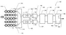
- FIG. 1illustrates a block diagram of a receiver assembly, in accordance with a preferred embodiment of the present invention.
- the present inventionis a receiver assembly 100 .
- the receiver assembly 100comprises an N-array antenna assembly 110 , a down converter 120 , a demodulator 130 , a latch 140 , a first-in/first-out circuit (FIFO) 150 , and logic 160 .
- the receiver assembly 100obtains an analog signal from the air.
- the analog signalas it is fed through the receive assembly 100 , is converted to a digital signal. Accomplishing this analog to digital conversion is not an easy task at high frequencies and high data speeds.
- the present inventionis implemented with the combination of three over-arching concepts—antenna diversity, selection diversity (SD), and maximum ration combining (MRC).
- the present inventionpreferably, operates at approximately 60 GHz, i.e., 54 to 66 GHz, and at approximately 10 Gb/s.
- the N-array antenna assembly 110includes N (number) fan beam series array antenna 112 . That is, the N-array antenna assembly 110 includes a plurality of antennas 112 . As illustrated in FIG. 1 , there are 5 array antennas 112 ; one skilled in the art would recognize that many antennas 112 can be implemented. Each antenna 112 can be designed to provide approximately 10 dBi of gain, an azimuth (i.e., H-plane) of approximately 3 dB having a beam-width of approximately 60 degrees, and an elevation (i.e., E-plane) of approximately 3 dB having a beam-width of approximately 30 to 35 degrees, the combination of which can present unexpected results.
- the selected N fan beam antennas 112 for the receiver assembly 100are different from one another, wherein, for instance, the antennas 112 have different gain, radiation patterns, shapes, sizes, and other differing characteristics between the antennas 112 .
- the antennas 112can be designed, further, to have different elevation beam orientations.
- the association of the different N antennas 112can cover approximately 60 degrees in the azimuth plane, and approximately 180 degrees in the elevation plane.
- the N-array antenna assembly 110includes three (3) antennas 112 , the antennas 112 can cover approximately 180 in at least 2 planes.
- the antenna 112can be designed to receive an analog signal 105 , preferably operating at approximately 60 GHz.
- each antenna 112is less sensitive to a multi-path effect. Additionally, due to different beam orientations of the antenna 112 , each antenna 112 can receive, preferably, a line of sight signal, or, alternatively, a reflected signal (for instance, from a wireless repeater).
- the arrangement of the antennas 112 , as well as the plurality of antennas 112 , of the N-array antenna assembly 110can enable a variety of angles, wherein enabling the receiver assembly 100 to receive a number of different signals, or the same signal, at different strengths.
- Each antenna 112is connected to an amplifier 114 .
- the amplifier 114is a low noise amplifier (LNA).
- LNAlow noise amplifier
- the selection diversity conceptcan be applied to select antennas 112 that exhibit, or provide, the highest signal-to-noise ratio (SNR). That is, the selection diversity format enables the best signal to be calculated.
- the antenna 112 that provides the best signalhas that signal secured, while weaker signals are eliminated.
- the amplifier 114can emit a signal 117 .
- the signal 117 emitted from the amplifier 114can then be fed into a down converter 120 .
- the down converter 120can be adapted to perform frequency conversion to a lower frequency band.
- the down converter 120can emit a signal 125 .
- the signal 125 emitted from the down converter 120is, preferably, fed next into a demodulator 130 .
- the demodulator 130can convert the signal 125 from the down converter 120 to a baseband signal. Indeed, the demodulator 130 is adapted to recover the signal 125 and further recover data from the signal 125 , thus improving the signal 125 , by preferred analog techniques.
- the demodulator 130includes clock-recovery technology 132 and data-recovery technology 134 .
- the clock-recovery 132 and data-recovery 134are applied to the signal 125 emitting from the down converter 120 .
- the application of the clock-recovery 132 and data-recovery 134can create streams of bits that can be synchronized with latch functionality.
- the latch 140can realign the signal 135 , which is dependent on the bit rate. A delay in the signal patch can be realigned in the latch 140 .
- the latch 140can take the signal 135 and hold it for a predetermined time in order to align it from another signal 137 from the demodulator 130 , which can be received and fed from a different antenna through the receiver assembly, but can lag (time) a little behind the signal 135 .
- the realignmentis also dependent on the bit rate.
- the FIFO 150can use SERDES (serializer/deserializer) architecture.
- the SERDEScan covert the signal 145 from/to a serial data stream and a parallel data stream.
- the signal 155 from the FIFO 150can be then fed into a logic circuit 160 .
- the logic 160can include coding to correlate known sequences of bits.
- the logic 160can, preferably, include error detection 162 and error correction algorithms 164 .
- error detection 162 coding within the logic 160can correlate streams of data.
- a maximum ratiowhich can combine and take different input signals to correlate and assign weights, or preferences, of the signals.
- An analog signal to noise ratio 166can be used to enables determining the weight of the signal.
- the signal 165 emitted from the logic 160is a digital signal.
- the analog signal 105 received by one or more antennas, as the signal runs through the receiver assembly,is converted to a digital signal.
Landscapes
- Engineering & Computer Science (AREA)
- Computer Networks & Wireless Communication (AREA)
- Signal Processing (AREA)
- Radio Transmission System (AREA)
- Mobile Radio Communication Systems (AREA)
Abstract
Description
Claims (15)
Priority Applications (1)
| Application Number | Priority Date | Filing Date | Title |
|---|---|---|---|
| US11/394,497US7593704B2 (en) | 2005-03-31 | 2006-03-31 | Receiver assembly and method for multi-gigabit wireless systems |
Applications Claiming Priority (9)
| Application Number | Priority Date | Filing Date | Title |
|---|---|---|---|
| US66684005P | 2005-03-31 | 2005-03-31 | |
| US66683905P | 2005-03-31 | 2005-03-31 | |
| US66737505P | 2005-04-01 | 2005-04-01 | |
| US66745805P | 2005-04-01 | 2005-04-01 | |
| US66731305P | 2005-04-01 | 2005-04-01 | |
| US66731205P | 2005-04-01 | 2005-04-01 | |
| US66728705P | 2005-04-01 | 2005-04-01 | |
| US66744305P | 2005-04-01 | 2005-04-01 | |
| US11/394,497US7593704B2 (en) | 2005-03-31 | 2006-03-31 | Receiver assembly and method for multi-gigabit wireless systems |
Publications (2)
| Publication Number | Publication Date |
|---|---|
| US20060232469A1 US20060232469A1 (en) | 2006-10-19 |
| US7593704B2true US7593704B2 (en) | 2009-09-22 |
Family
ID=37108011
Family Applications (1)
| Application Number | Title | Priority Date | Filing Date |
|---|---|---|---|
| US11/394,497Active2027-07-21US7593704B2 (en) | 2005-03-31 | 2006-03-31 | Receiver assembly and method for multi-gigabit wireless systems |
Country Status (1)
| Country | Link |
|---|---|
| US (1) | US7593704B2 (en) |
Cited By (49)
| Publication number | Priority date | Publication date | Assignee | Title |
|---|---|---|---|---|
| US20110317595A1 (en)* | 2009-03-12 | 2011-12-29 | Canon Kabushiki Kaisha | Wireless communication apparatus, controlling method thereof, and program |
| US8532492B2 (en) | 2009-02-03 | 2013-09-10 | Corning Cable Systems Llc | Optical fiber-based distributed antenna systems, components, and related methods for calibration thereof |
| US8639121B2 (en) | 2009-11-13 | 2014-01-28 | Corning Cable Systems Llc | Radio-over-fiber (RoF) system for protocol-independent wired and/or wireless communication |
| US8644844B2 (en) | 2007-12-20 | 2014-02-04 | Corning Mobileaccess Ltd. | Extending outdoor location based services and applications into enclosed areas |
| US20140210666A1 (en)* | 2013-01-25 | 2014-07-31 | Alexander Maltsev | Apparatus, system and method of wireless communication via an antenna array |
| US8831428B2 (en) | 2010-02-15 | 2014-09-09 | Corning Optical Communications LLC | Dynamic cell bonding (DCB) for radio-over-fiber (RoF)-based networks and communication systems and related methods |
| US8873585B2 (en) | 2006-12-19 | 2014-10-28 | Corning Optical Communications Wireless Ltd | Distributed antenna system for MIMO technologies |
| US8983301B2 (en) | 2010-03-31 | 2015-03-17 | Corning Optical Communications LLC | Localization services in optical fiber-based distributed communications components and systems, and related methods |
| US9158864B2 (en) | 2012-12-21 | 2015-10-13 | Corning Optical Communications Wireless Ltd | Systems, methods, and devices for documenting a location of installed equipment |
| US9178635B2 (en) | 2014-01-03 | 2015-11-03 | Corning Optical Communications Wireless Ltd | Separation of communication signal sub-bands in distributed antenna systems (DASs) to reduce interference |
| US9184843B2 (en) | 2011-04-29 | 2015-11-10 | Corning Optical Communications LLC | Determining propagation delay of communications in distributed antenna systems, and related components, systems, and methods |
| US9185674B2 (en) | 2010-08-09 | 2015-11-10 | Corning Cable Systems Llc | Apparatuses, systems, and methods for determining location of a mobile device(s) in a distributed antenna system(s) |
| US9219546B2 (en) | 2011-12-12 | 2015-12-22 | Corning Optical Communications LLC | Extremely high frequency (EHF) distributed antenna systems, and related components and methods |
| US9240835B2 (en) | 2011-04-29 | 2016-01-19 | Corning Optical Communications LLC | Systems, methods, and devices for increasing radio frequency (RF) power in distributed antenna systems |
| US9247543B2 (en) | 2013-07-23 | 2016-01-26 | Corning Optical Communications Wireless Ltd | Monitoring non-supported wireless spectrum within coverage areas of distributed antenna systems (DASs) |
| US9258052B2 (en) | 2012-03-30 | 2016-02-09 | Corning Optical Communications LLC | Reducing location-dependent interference in distributed antenna systems operating in multiple-input, multiple-output (MIMO) configuration, and related components, systems, and methods |
| US9323020B2 (en) | 2008-10-09 | 2016-04-26 | Corning Cable Systems (Shanghai) Co. Ltd | Fiber optic terminal having adapter panel supporting both input and output fibers from an optical splitter |
| US9357551B2 (en) | 2014-05-30 | 2016-05-31 | Corning Optical Communications Wireless Ltd | Systems and methods for simultaneous sampling of serial digital data streams from multiple analog-to-digital converters (ADCS), including in distributed antenna systems |
| US9385810B2 (en) | 2013-09-30 | 2016-07-05 | Corning Optical Communications Wireless Ltd | Connection mapping in distributed communication systems |
| US9420542B2 (en) | 2014-09-25 | 2016-08-16 | Corning Optical Communications Wireless Ltd | System-wide uplink band gain control in a distributed antenna system (DAS), based on per band gain control of remote uplink paths in remote units |
| US9455784B2 (en) | 2012-10-31 | 2016-09-27 | Corning Optical Communications Wireless Ltd | Deployable wireless infrastructures and methods of deploying wireless infrastructures |
| US9525472B2 (en) | 2014-07-30 | 2016-12-20 | Corning Incorporated | Reducing location-dependent destructive interference in distributed antenna systems (DASS) operating in multiple-input, multiple-output (MIMO) configuration, and related components, systems, and methods |
| US9531452B2 (en) | 2012-11-29 | 2016-12-27 | Corning Optical Communications LLC | Hybrid intra-cell / inter-cell remote unit antenna bonding in multiple-input, multiple-output (MIMO) distributed antenna systems (DASs) |
| US9538138B2 (en) | 2013-06-05 | 2017-01-03 | Puddle Innovations | System for providing access to shared multimedia content |
| US9547145B2 (en) | 2010-10-19 | 2017-01-17 | Corning Optical Communications LLC | Local convergence point for multiple dwelling unit fiber optic distribution network |
| US9590733B2 (en) | 2009-07-24 | 2017-03-07 | Corning Optical Communications LLC | Location tracking using fiber optic array cables and related systems and methods |
| US9602210B2 (en) | 2014-09-24 | 2017-03-21 | Corning Optical Communications Wireless Ltd | Flexible head-end chassis supporting automatic identification and interconnection of radio interface modules and optical interface modules in an optical fiber-based distributed antenna system (DAS) |
| US9621293B2 (en) | 2012-08-07 | 2017-04-11 | Corning Optical Communications Wireless Ltd | Distribution of time-division multiplexed (TDM) management services in a distributed antenna system, and related components, systems, and methods |
| US9648580B1 (en) | 2016-03-23 | 2017-05-09 | Corning Optical Communications Wireless Ltd | Identifying remote units in a wireless distribution system (WDS) based on assigned unique temporal delay patterns |
| US9647758B2 (en) | 2012-11-30 | 2017-05-09 | Corning Optical Communications Wireless Ltd | Cabling connectivity monitoring and verification |
| US9661781B2 (en) | 2013-07-31 | 2017-05-23 | Corning Optical Communications Wireless Ltd | Remote units for distributed communication systems and related installation methods and apparatuses |
| US9673904B2 (en) | 2009-02-03 | 2017-06-06 | Corning Optical Communications LLC | Optical fiber-based distributed antenna systems, components, and related methods for calibration thereof |
| US9681313B2 (en) | 2015-04-15 | 2017-06-13 | Corning Optical Communications Wireless Ltd | Optimizing remote antenna unit performance using an alternative data channel |
| US9698852B2 (en) | 2012-10-30 | 2017-07-04 | Maja Systems, Inc. | Compact and low-power millimeter-wave integrated VCO-up/down-converter with gain-boosting |
| US9715157B2 (en) | 2013-06-12 | 2017-07-25 | Corning Optical Communications Wireless Ltd | Voltage controlled optical directional coupler |
| US9729267B2 (en) | 2014-12-11 | 2017-08-08 | Corning Optical Communications Wireless Ltd | Multiplexing two separate optical links with the same wavelength using asymmetric combining and splitting |
| US9730228B2 (en) | 2014-08-29 | 2017-08-08 | Corning Optical Communications Wireless Ltd | Individualized gain control of remote uplink band paths in a remote unit in a distributed antenna system (DAS), based on combined uplink power level in the remote unit |
| US9775123B2 (en) | 2014-03-28 | 2017-09-26 | Corning Optical Communications Wireless Ltd. | Individualized gain control of uplink paths in remote units in a distributed antenna system (DAS) based on individual remote unit contribution to combined uplink power |
| US9781553B2 (en) | 2012-04-24 | 2017-10-03 | Corning Optical Communications LLC | Location based services in a distributed communication system, and related components and methods |
| US9807700B2 (en) | 2015-02-19 | 2017-10-31 | Corning Optical Communications Wireless Ltd | Offsetting unwanted downlink interference signals in an uplink path in a distributed antenna system (DAS) |
| US9948349B2 (en) | 2015-07-17 | 2018-04-17 | Corning Optical Communications Wireless Ltd | IOT automation and data collection system |
| US9974074B2 (en) | 2013-06-12 | 2018-05-15 | Corning Optical Communications Wireless Ltd | Time-division duplexing (TDD) in distributed communications systems, including distributed antenna systems (DASs) |
| US10110307B2 (en) | 2012-03-02 | 2018-10-23 | Corning Optical Communications LLC | Optical network units (ONUs) for high bandwidth connectivity, and related components and methods |
| US10128951B2 (en) | 2009-02-03 | 2018-11-13 | Corning Optical Communications LLC | Optical fiber-based distributed antenna systems, components, and related methods for monitoring and configuring thereof |
| US10136200B2 (en) | 2012-04-25 | 2018-11-20 | Corning Optical Communications LLC | Distributed antenna system architectures |
| US10236924B2 (en) | 2016-03-31 | 2019-03-19 | Corning Optical Communications Wireless Ltd | Reducing out-of-channel noise in a wireless distribution system (WDS) |
| US10560214B2 (en) | 2015-09-28 | 2020-02-11 | Corning Optical Communications LLC | Downlink and uplink communication path switching in a time-division duplex (TDD) distributed antenna system (DAS) |
| US11276916B2 (en) | 2019-01-25 | 2022-03-15 | Samsung Electronics Co., Ltd. | Electronic device comprising antenna module |
| US11671914B2 (en) | 2010-10-13 | 2023-06-06 | Corning Optical Communications LLC | Power management for remote antenna units in distributed antenna systems |
Families Citing this family (1)
| Publication number | Priority date | Publication date | Assignee | Title |
|---|---|---|---|---|
| JP7314257B2 (en) | 2018-09-19 | 2023-07-25 | アカーシュ・システムズ・インコーポレイテッド | System and method for satellite communications |
Citations (17)
| Publication number | Priority date | Publication date | Assignee | Title |
|---|---|---|---|---|
| US6006072A (en) | 1997-03-28 | 1999-12-21 | Nec Corporation | Method and apparatus for interference cancellation |
| US6157621A (en)* | 1991-10-28 | 2000-12-05 | Teledesic Llc | Satellite communication system |
| US6351508B1 (en) | 1999-11-17 | 2002-02-26 | Transwitch Corporation | Phase/frequency detector for dejitter applications |
| US20040002307A1 (en)* | 2002-05-16 | 2004-01-01 | Yoshitaka Mizoguchi | Diversity system and diversity method |
| US6901123B2 (en)* | 2001-04-02 | 2005-05-31 | Harris Corporation | Multi-panel phased array antenna, employing combined baseband decision driven carrier demodulation |
| US6980586B1 (en)* | 1999-05-24 | 2005-12-27 | Intel Corporation | Pseudo-noise encoded digital data clock recovery |
| US20060067442A1 (en) | 2002-06-03 | 2006-03-30 | Toa Corporation | Digital wireless receiver using antenna diversity method |
| US20060073802A1 (en)* | 2004-09-29 | 2006-04-06 | Sujai Chari | Phase combining diversity |
| US20060094385A1 (en)* | 2004-11-04 | 2006-05-04 | Hamid Rafati | Architecture for multiple-antenna systems |
| US20060126750A1 (en)* | 1998-02-04 | 2006-06-15 | Friedman Robert F | Method and apparatus for combining transponders on multiple satellites into virtual channels |
| US20060187100A1 (en)* | 2004-03-30 | 2006-08-24 | Kabushiki Kaisha Toshiba | Multiple input analog-to-digital conversion apparatus and radio receiver using the same |
| US20060193410A1 (en)* | 2005-02-28 | 2006-08-31 | Moorti R T | Gain estimation for multiple receiver systems |
| US7167727B2 (en)* | 2000-06-12 | 2007-01-23 | Broadcom Corporation | Wireless data communications using FIFO for synchronization memory |
| US20070024506A1 (en)* | 2005-07-29 | 2007-02-01 | Sony Corporation | Systems and methods for high frequency parallel transmissions |
| US20070091988A1 (en)* | 2005-10-26 | 2007-04-26 | Sadri Ali S | Systems for communicating using multiple frequency bands in a wireless network |
| US20080002652A1 (en)* | 2004-11-10 | 2008-01-03 | Gupta Dev V | System and apparatus for high data rate wireless communications |
| US7394870B2 (en)* | 2003-04-04 | 2008-07-01 | Silicon Storage Technology, Inc. | Low complexity synchronization for wireless transmission |
- 2006
- 2006-03-31USUS11/394,497patent/US7593704B2/enactiveActive
Patent Citations (17)
| Publication number | Priority date | Publication date | Assignee | Title |
|---|---|---|---|---|
| US6157621A (en)* | 1991-10-28 | 2000-12-05 | Teledesic Llc | Satellite communication system |
| US6006072A (en) | 1997-03-28 | 1999-12-21 | Nec Corporation | Method and apparatus for interference cancellation |
| US20060126750A1 (en)* | 1998-02-04 | 2006-06-15 | Friedman Robert F | Method and apparatus for combining transponders on multiple satellites into virtual channels |
| US6980586B1 (en)* | 1999-05-24 | 2005-12-27 | Intel Corporation | Pseudo-noise encoded digital data clock recovery |
| US6351508B1 (en) | 1999-11-17 | 2002-02-26 | Transwitch Corporation | Phase/frequency detector for dejitter applications |
| US7167727B2 (en)* | 2000-06-12 | 2007-01-23 | Broadcom Corporation | Wireless data communications using FIFO for synchronization memory |
| US6901123B2 (en)* | 2001-04-02 | 2005-05-31 | Harris Corporation | Multi-panel phased array antenna, employing combined baseband decision driven carrier demodulation |
| US20040002307A1 (en)* | 2002-05-16 | 2004-01-01 | Yoshitaka Mizoguchi | Diversity system and diversity method |
| US20060067442A1 (en) | 2002-06-03 | 2006-03-30 | Toa Corporation | Digital wireless receiver using antenna diversity method |
| US7394870B2 (en)* | 2003-04-04 | 2008-07-01 | Silicon Storage Technology, Inc. | Low complexity synchronization for wireless transmission |
| US20060187100A1 (en)* | 2004-03-30 | 2006-08-24 | Kabushiki Kaisha Toshiba | Multiple input analog-to-digital conversion apparatus and radio receiver using the same |
| US20060073802A1 (en)* | 2004-09-29 | 2006-04-06 | Sujai Chari | Phase combining diversity |
| US20060094385A1 (en)* | 2004-11-04 | 2006-05-04 | Hamid Rafati | Architecture for multiple-antenna systems |
| US20080002652A1 (en)* | 2004-11-10 | 2008-01-03 | Gupta Dev V | System and apparatus for high data rate wireless communications |
| US20060193410A1 (en)* | 2005-02-28 | 2006-08-31 | Moorti R T | Gain estimation for multiple receiver systems |
| US20070024506A1 (en)* | 2005-07-29 | 2007-02-01 | Sony Corporation | Systems and methods for high frequency parallel transmissions |
| US20070091988A1 (en)* | 2005-10-26 | 2007-04-26 | Sadri Ali S | Systems for communicating using multiple frequency bands in a wireless network |
Non-Patent Citations (2)
| Title |
|---|
| International Search Report and Written Opinion for corresponding PCT case, International Application No. PCT/US2006/017014, dated Jan. 24, 2007. |
| Murakami, Yasushi et al., "A Switchable Multi-Sector Antenna for Indoor Wireless LAN Systems in the 60-GHz Band", IEEE Transactions On Microwave Theory And Techniques, vol. 46, No. 6, Jun. 1998, pp. 841-843. |
Cited By (93)
| Publication number | Priority date | Publication date | Assignee | Title |
|---|---|---|---|---|
| US9130613B2 (en) | 2006-12-19 | 2015-09-08 | Corning Optical Communications Wireless Ltd | Distributed antenna system for MIMO technologies |
| US8873585B2 (en) | 2006-12-19 | 2014-10-28 | Corning Optical Communications Wireless Ltd | Distributed antenna system for MIMO technologies |
| US8644844B2 (en) | 2007-12-20 | 2014-02-04 | Corning Mobileaccess Ltd. | Extending outdoor location based services and applications into enclosed areas |
| US9323020B2 (en) | 2008-10-09 | 2016-04-26 | Corning Cable Systems (Shanghai) Co. Ltd | Fiber optic terminal having adapter panel supporting both input and output fibers from an optical splitter |
| US8532492B2 (en) | 2009-02-03 | 2013-09-10 | Corning Cable Systems Llc | Optical fiber-based distributed antenna systems, components, and related methods for calibration thereof |
| US9673904B2 (en) | 2009-02-03 | 2017-06-06 | Corning Optical Communications LLC | Optical fiber-based distributed antenna systems, components, and related methods for calibration thereof |
| US10153841B2 (en) | 2009-02-03 | 2018-12-11 | Corning Optical Communications LLC | Optical fiber-based distributed antenna systems, components, and related methods for calibration thereof |
| US9900097B2 (en) | 2009-02-03 | 2018-02-20 | Corning Optical Communications LLC | Optical fiber-based distributed antenna systems, components, and related methods for calibration thereof |
| US10128951B2 (en) | 2009-02-03 | 2018-11-13 | Corning Optical Communications LLC | Optical fiber-based distributed antenna systems, components, and related methods for monitoring and configuring thereof |
| US9112611B2 (en) | 2009-02-03 | 2015-08-18 | Corning Optical Communications LLC | Optical fiber-based distributed antenna systems, components, and related methods for calibration thereof |
| US8917637B2 (en)* | 2009-03-12 | 2014-12-23 | Canon Kabushiki Kaisha | Apparatus and methods for conducting full-duplex wireless communication with a communication partner |
| US20110317595A1 (en)* | 2009-03-12 | 2011-12-29 | Canon Kabushiki Kaisha | Wireless communication apparatus, controlling method thereof, and program |
| US9590733B2 (en) | 2009-07-24 | 2017-03-07 | Corning Optical Communications LLC | Location tracking using fiber optic array cables and related systems and methods |
| US10070258B2 (en) | 2009-07-24 | 2018-09-04 | Corning Optical Communications LLC | Location tracking using fiber optic array cables and related systems and methods |
| US9485022B2 (en) | 2009-11-13 | 2016-11-01 | Corning Optical Communications LLC | Radio-over-fiber (ROF) system for protocol-independent wired and/or wireless communication |
| US8639121B2 (en) | 2009-11-13 | 2014-01-28 | Corning Cable Systems Llc | Radio-over-fiber (RoF) system for protocol-independent wired and/or wireless communication |
| US9219879B2 (en) | 2009-11-13 | 2015-12-22 | Corning Optical Communications LLC | Radio-over-fiber (ROF) system for protocol-independent wired and/or wireless communication |
| US9729238B2 (en) | 2009-11-13 | 2017-08-08 | Corning Optical Communications LLC | Radio-over-fiber (ROF) system for protocol-independent wired and/or wireless communication |
| US9319138B2 (en) | 2010-02-15 | 2016-04-19 | Corning Optical Communications LLC | Dynamic cell bonding (DCB) for radio-over-fiber (RoF)-based networks and communication systems and related methods |
| US8831428B2 (en) | 2010-02-15 | 2014-09-09 | Corning Optical Communications LLC | Dynamic cell bonding (DCB) for radio-over-fiber (RoF)-based networks and communication systems and related methods |
| US9967032B2 (en) | 2010-03-31 | 2018-05-08 | Corning Optical Communications LLC | Localization services in optical fiber-based distributed communications components and systems, and related methods |
| US8983301B2 (en) | 2010-03-31 | 2015-03-17 | Corning Optical Communications LLC | Localization services in optical fiber-based distributed communications components and systems, and related methods |
| US10448205B2 (en) | 2010-08-09 | 2019-10-15 | Corning Optical Communications LLC | Apparatuses, systems, and methods for determining location of a mobile device(s) in a distributed antenna system(s) |
| US9185674B2 (en) | 2010-08-09 | 2015-11-10 | Corning Cable Systems Llc | Apparatuses, systems, and methods for determining location of a mobile device(s) in a distributed antenna system(s) |
| US10959047B2 (en) | 2010-08-09 | 2021-03-23 | Corning Optical Communications LLC | Apparatuses, systems, and methods for determining location of a mobile device(s) in a distributed antenna system(s) |
| US9913094B2 (en) | 2010-08-09 | 2018-03-06 | Corning Optical Communications LLC | Apparatuses, systems, and methods for determining location of a mobile device(s) in a distributed antenna system(s) |
| US11653175B2 (en) | 2010-08-09 | 2023-05-16 | Corning Optical Communications LLC | Apparatuses, systems, and methods for determining location of a mobile device(s) in a distributed antenna system(s) |
| US12160789B2 (en) | 2010-08-09 | 2024-12-03 | Corning Optical Communications LLC | Apparatuses, systems, and methods for determining location of a mobile device(s) in a distributed antenna system(s) |
| US11671914B2 (en) | 2010-10-13 | 2023-06-06 | Corning Optical Communications LLC | Power management for remote antenna units in distributed antenna systems |
| US9720197B2 (en) | 2010-10-19 | 2017-08-01 | Corning Optical Communications LLC | Transition box for multiple dwelling unit fiber optic distribution network |
| US9547145B2 (en) | 2010-10-19 | 2017-01-17 | Corning Optical Communications LLC | Local convergence point for multiple dwelling unit fiber optic distribution network |
| US9240835B2 (en) | 2011-04-29 | 2016-01-19 | Corning Optical Communications LLC | Systems, methods, and devices for increasing radio frequency (RF) power in distributed antenna systems |
| US9369222B2 (en) | 2011-04-29 | 2016-06-14 | Corning Optical Communications LLC | Determining propagation delay of communications in distributed antenna systems, and related components, systems, and methods |
| US9184843B2 (en) | 2011-04-29 | 2015-11-10 | Corning Optical Communications LLC | Determining propagation delay of communications in distributed antenna systems, and related components, systems, and methods |
| US9806797B2 (en) | 2011-04-29 | 2017-10-31 | Corning Optical Communications LLC | Systems, methods, and devices for increasing radio frequency (RF) power in distributed antenna systems |
| US10148347B2 (en) | 2011-04-29 | 2018-12-04 | Corning Optical Communications LLC | Systems, methods, and devices for increasing radio frequency (RF) power in distributed antenna systems |
| US9807722B2 (en) | 2011-04-29 | 2017-10-31 | Corning Optical Communications LLC | Determining propagation delay of communications in distributed antenna systems, and related components, systems, and methods |
| US10110305B2 (en) | 2011-12-12 | 2018-10-23 | Corning Optical Communications LLC | Extremely high frequency (EHF) distributed antenna systems, and related components and methods |
| US9602209B2 (en) | 2011-12-12 | 2017-03-21 | Corning Optical Communications LLC | Extremely high frequency (EHF) distributed antenna systems, and related components and methods |
| US9219546B2 (en) | 2011-12-12 | 2015-12-22 | Corning Optical Communications LLC | Extremely high frequency (EHF) distributed antenna systems, and related components and methods |
| US9800339B2 (en) | 2011-12-12 | 2017-10-24 | Corning Optical Communications LLC | Extremely high frequency (EHF) distributed antenna systems, and related components and methods |
| US10110307B2 (en) | 2012-03-02 | 2018-10-23 | Corning Optical Communications LLC | Optical network units (ONUs) for high bandwidth connectivity, and related components and methods |
| US9813127B2 (en) | 2012-03-30 | 2017-11-07 | Corning Optical Communications LLC | Reducing location-dependent interference in distributed antenna systems operating in multiple-input, multiple-output (MIMO) configuration, and related components, systems, and methods |
| US9258052B2 (en) | 2012-03-30 | 2016-02-09 | Corning Optical Communications LLC | Reducing location-dependent interference in distributed antenna systems operating in multiple-input, multiple-output (MIMO) configuration, and related components, systems, and methods |
| US9781553B2 (en) | 2012-04-24 | 2017-10-03 | Corning Optical Communications LLC | Location based services in a distributed communication system, and related components and methods |
| US10136200B2 (en) | 2012-04-25 | 2018-11-20 | Corning Optical Communications LLC | Distributed antenna system architectures |
| US10349156B2 (en) | 2012-04-25 | 2019-07-09 | Corning Optical Communications LLC | Distributed antenna system architectures |
| US9973968B2 (en) | 2012-08-07 | 2018-05-15 | Corning Optical Communications Wireless Ltd | Distribution of time-division multiplexed (TDM) management services in a distributed antenna system, and related components, systems, and methods |
| US9621293B2 (en) | 2012-08-07 | 2017-04-11 | Corning Optical Communications Wireless Ltd | Distribution of time-division multiplexed (TDM) management services in a distributed antenna system, and related components, systems, and methods |
| US9698852B2 (en) | 2012-10-30 | 2017-07-04 | Maja Systems, Inc. | Compact and low-power millimeter-wave integrated VCO-up/down-converter with gain-boosting |
| US10498382B2 (en) | 2012-10-30 | 2019-12-03 | Maja Systems | Millimeter-wave mixed-signal automatic gain control |
| US9455784B2 (en) | 2012-10-31 | 2016-09-27 | Corning Optical Communications Wireless Ltd | Deployable wireless infrastructures and methods of deploying wireless infrastructures |
| US9531452B2 (en) | 2012-11-29 | 2016-12-27 | Corning Optical Communications LLC | Hybrid intra-cell / inter-cell remote unit antenna bonding in multiple-input, multiple-output (MIMO) distributed antenna systems (DASs) |
| US10361782B2 (en) | 2012-11-30 | 2019-07-23 | Corning Optical Communications LLC | Cabling connectivity monitoring and verification |
| US9647758B2 (en) | 2012-11-30 | 2017-05-09 | Corning Optical Communications Wireless Ltd | Cabling connectivity monitoring and verification |
| US9158864B2 (en) | 2012-12-21 | 2015-10-13 | Corning Optical Communications Wireless Ltd | Systems, methods, and devices for documenting a location of installed equipment |
| US9414192B2 (en) | 2012-12-21 | 2016-08-09 | Corning Optical Communications Wireless Ltd | Systems, methods, and devices for documenting a location of installed equipment |
| US20140210666A1 (en)* | 2013-01-25 | 2014-07-31 | Alexander Maltsev | Apparatus, system and method of wireless communication via an antenna array |
| US9538138B2 (en) | 2013-06-05 | 2017-01-03 | Puddle Innovations | System for providing access to shared multimedia content |
| US11291001B2 (en) | 2013-06-12 | 2022-03-29 | Corning Optical Communications LLC | Time-division duplexing (TDD) in distributed communications systems, including distributed antenna systems (DASs) |
| US9715157B2 (en) | 2013-06-12 | 2017-07-25 | Corning Optical Communications Wireless Ltd | Voltage controlled optical directional coupler |
| US9974074B2 (en) | 2013-06-12 | 2018-05-15 | Corning Optical Communications Wireless Ltd | Time-division duplexing (TDD) in distributed communications systems, including distributed antenna systems (DASs) |
| US11792776B2 (en) | 2013-06-12 | 2023-10-17 | Corning Optical Communications LLC | Time-division duplexing (TDD) in distributed communications systems, including distributed antenna systems (DASs) |
| US9247543B2 (en) | 2013-07-23 | 2016-01-26 | Corning Optical Communications Wireless Ltd | Monitoring non-supported wireless spectrum within coverage areas of distributed antenna systems (DASs) |
| US9526020B2 (en) | 2013-07-23 | 2016-12-20 | Corning Optical Communications Wireless Ltd | Monitoring non-supported wireless spectrum within coverage areas of distributed antenna systems (DASs) |
| US9967754B2 (en) | 2013-07-23 | 2018-05-08 | Corning Optical Communications Wireless Ltd | Monitoring non-supported wireless spectrum within coverage areas of distributed antenna systems (DASs) |
| US10292056B2 (en) | 2013-07-23 | 2019-05-14 | Corning Optical Communications LLC | Monitoring non-supported wireless spectrum within coverage areas of distributed antenna systems (DASs) |
| US9661781B2 (en) | 2013-07-31 | 2017-05-23 | Corning Optical Communications Wireless Ltd | Remote units for distributed communication systems and related installation methods and apparatuses |
| US9385810B2 (en) | 2013-09-30 | 2016-07-05 | Corning Optical Communications Wireless Ltd | Connection mapping in distributed communication systems |
| US9178635B2 (en) | 2014-01-03 | 2015-11-03 | Corning Optical Communications Wireless Ltd | Separation of communication signal sub-bands in distributed antenna systems (DASs) to reduce interference |
| US9775123B2 (en) | 2014-03-28 | 2017-09-26 | Corning Optical Communications Wireless Ltd. | Individualized gain control of uplink paths in remote units in a distributed antenna system (DAS) based on individual remote unit contribution to combined uplink power |
| US9807772B2 (en) | 2014-05-30 | 2017-10-31 | Corning Optical Communications Wireless Ltd. | Systems and methods for simultaneous sampling of serial digital data streams from multiple analog-to-digital converters (ADCs), including in distributed antenna systems |
| US9357551B2 (en) | 2014-05-30 | 2016-05-31 | Corning Optical Communications Wireless Ltd | Systems and methods for simultaneous sampling of serial digital data streams from multiple analog-to-digital converters (ADCS), including in distributed antenna systems |
| US9525472B2 (en) | 2014-07-30 | 2016-12-20 | Corning Incorporated | Reducing location-dependent destructive interference in distributed antenna systems (DASS) operating in multiple-input, multiple-output (MIMO) configuration, and related components, systems, and methods |
| US9929786B2 (en) | 2014-07-30 | 2018-03-27 | Corning Incorporated | Reducing location-dependent destructive interference in distributed antenna systems (DASS) operating in multiple-input, multiple-output (MIMO) configuration, and related components, systems, and methods |
| US10256879B2 (en) | 2014-07-30 | 2019-04-09 | Corning Incorporated | Reducing location-dependent destructive interference in distributed antenna systems (DASS) operating in multiple-input, multiple-output (MIMO) configuration, and related components, systems, and methods |
| US9730228B2 (en) | 2014-08-29 | 2017-08-08 | Corning Optical Communications Wireless Ltd | Individualized gain control of remote uplink band paths in a remote unit in a distributed antenna system (DAS), based on combined uplink power level in the remote unit |
| US10397929B2 (en) | 2014-08-29 | 2019-08-27 | Corning Optical Communications LLC | Individualized gain control of remote uplink band paths in a remote unit in a distributed antenna system (DAS), based on combined uplink power level in the remote unit |
| US9602210B2 (en) | 2014-09-24 | 2017-03-21 | Corning Optical Communications Wireless Ltd | Flexible head-end chassis supporting automatic identification and interconnection of radio interface modules and optical interface modules in an optical fiber-based distributed antenna system (DAS) |
| US9929810B2 (en) | 2014-09-24 | 2018-03-27 | Corning Optical Communications Wireless Ltd | Flexible head-end chassis supporting automatic identification and interconnection of radio interface modules and optical interface modules in an optical fiber-based distributed antenna system (DAS) |
| US9420542B2 (en) | 2014-09-25 | 2016-08-16 | Corning Optical Communications Wireless Ltd | System-wide uplink band gain control in a distributed antenna system (DAS), based on per band gain control of remote uplink paths in remote units |
| US9788279B2 (en) | 2014-09-25 | 2017-10-10 | Corning Optical Communications Wireless Ltd | System-wide uplink band gain control in a distributed antenna system (DAS), based on per-band gain control of remote uplink paths in remote units |
| US10135561B2 (en) | 2014-12-11 | 2018-11-20 | Corning Optical Communications Wireless Ltd | Multiplexing two separate optical links with the same wavelength using asymmetric combining and splitting |
| US9729267B2 (en) | 2014-12-11 | 2017-08-08 | Corning Optical Communications Wireless Ltd | Multiplexing two separate optical links with the same wavelength using asymmetric combining and splitting |
| US9807700B2 (en) | 2015-02-19 | 2017-10-31 | Corning Optical Communications Wireless Ltd | Offsetting unwanted downlink interference signals in an uplink path in a distributed antenna system (DAS) |
| US10292114B2 (en) | 2015-02-19 | 2019-05-14 | Corning Optical Communications LLC | Offsetting unwanted downlink interference signals in an uplink path in a distributed antenna system (DAS) |
| US9681313B2 (en) | 2015-04-15 | 2017-06-13 | Corning Optical Communications Wireless Ltd | Optimizing remote antenna unit performance using an alternative data channel |
| US10009094B2 (en) | 2015-04-15 | 2018-06-26 | Corning Optical Communications Wireless Ltd | Optimizing remote antenna unit performance using an alternative data channel |
| US9948349B2 (en) | 2015-07-17 | 2018-04-17 | Corning Optical Communications Wireless Ltd | IOT automation and data collection system |
| US10560214B2 (en) | 2015-09-28 | 2020-02-11 | Corning Optical Communications LLC | Downlink and uplink communication path switching in a time-division duplex (TDD) distributed antenna system (DAS) |
| US9648580B1 (en) | 2016-03-23 | 2017-05-09 | Corning Optical Communications Wireless Ltd | Identifying remote units in a wireless distribution system (WDS) based on assigned unique temporal delay patterns |
| US10236924B2 (en) | 2016-03-31 | 2019-03-19 | Corning Optical Communications Wireless Ltd | Reducing out-of-channel noise in a wireless distribution system (WDS) |
| US11276916B2 (en) | 2019-01-25 | 2022-03-15 | Samsung Electronics Co., Ltd. | Electronic device comprising antenna module |
Also Published As
| Publication number | Publication date |
|---|---|
| US20060232469A1 (en) | 2006-10-19 |
Similar Documents
| Publication | Publication Date | Title |
|---|---|---|
| US7593704B2 (en) | Receiver assembly and method for multi-gigabit wireless systems | |
| US10686638B2 (en) | Wireless communication system to communicate using different beamwidths | |
| US7653163B2 (en) | Systems for communicating using multiple frequency bands in a wireless network | |
| US8331887B2 (en) | Antenna diversity system with multiple tuner circuits having multiple operating modes and methods | |
| US20040042561A1 (en) | Method and apparatus for receiving differential ultra wideband signals | |
| US20110158298A1 (en) | Tuner circuit with an inter-chip transmitter and method of providing an inter-chip link frame | |
| US20130089000A1 (en) | Beamforming training within a wireless communication system utilizing a directional antenna | |
| US20070024506A1 (en) | Systems and methods for high frequency parallel transmissions | |
| Cabric et al. | Future wireless systems: UWB, 60GHz, and cognitive radios | |
| US9071326B2 (en) | Distributed radio system | |
| US20090040107A1 (en) | Smart antenna subsystem | |
| CN109412628B (en) | An X-band broadband multi-beam digital receiving system and its signal processing method | |
| EP3041155B1 (en) | Multiple antenna distributed radio system | |
| EP2299607A3 (en) | Multicarrier transmit diversity in UTRAN for HSPA | |
| US9426842B2 (en) | Distributed radio system | |
| US20140177690A1 (en) | Link aggregation system, protection system, and cross polarization interference cancellation applications for all outdoor radios using wireless channels operating at a licensing-free 60 ghz band | |
| US20220376755A1 (en) | Multi-antenna channel estimation apparatus and method for beamforming | |
| WO2007130032A1 (en) | Receiver assembly and method for multi-gigabit wireless systems | |
| KR20090010072A (en) | Receiver Assembly and Method for Multi-Gigabit Wireless Systems | |
| JP2013135457A (en) | Relay device, terminal station, radio communication system, and relay method | |
| CN1855761A (en) | Wireless communication system, terminal and method | |
| US20070116105A1 (en) | Multiple receiver rf integrated circuit architecture | |
| KR100495536B1 (en) | Circularly polarized wave diversity apparatus using micro strip antenna and method thereof | |
| US11437719B2 (en) | Digital array signal processing method for an array receiver | |
| Smith | Polarization Diversity in Microwave Communication Systems |
Legal Events
| Date | Code | Title | Description |
|---|---|---|---|
| AS | Assignment | Owner name:GEORGIA TECH RESEARCH CORPORATION, GEORGIA Free format text:ASSIGNMENT OF ASSIGNORS INTEREST;ASSIGNORS:PINEL, STEPHANE;LASKAR, JOY;SIGNING DATES FROM 20060908 TO 20060928;REEL/FRAME:018351/0414 Owner name:GEORGIA TECH RESEARCH CORPORATION, GEORGIA Free format text:ASSIGNMENT OF ASSIGNORS INTEREST;ASSIGNORS:PINEL, STEPHANE;LASKAR, JOY;REEL/FRAME:018351/0414;SIGNING DATES FROM 20060908 TO 20060928 | |
| STCF | Information on status: patent grant | Free format text:PATENTED CASE | |
| FPAY | Fee payment | Year of fee payment:4 | |
| FPAY | Fee payment | Year of fee payment:8 | |
| FEPP | Fee payment procedure | Free format text:MAINTENANCE FEE REMINDER MAILED (ORIGINAL EVENT CODE: REM.); ENTITY STATUS OF PATENT OWNER: LARGE ENTITY | |
| FEPP | Fee payment procedure | Free format text:ENTITY STATUS SET TO SMALL (ORIGINAL EVENT CODE: SMAL); ENTITY STATUS OF PATENT OWNER: SMALL ENTITY | |
| FEPP | Fee payment procedure | Free format text:11.5 YR SURCHARGE- LATE PMT W/IN 6 MO, SMALL ENTITY (ORIGINAL EVENT CODE: M2556); ENTITY STATUS OF PATENT OWNER: SMALL ENTITY | |
| MAFP | Maintenance fee payment | Free format text:PAYMENT OF MAINTENANCE FEE, 12TH YR, SMALL ENTITY (ORIGINAL EVENT CODE: M2553); ENTITY STATUS OF PATENT OWNER: SMALL ENTITY Year of fee payment:12 |