US7593698B1 - Large signal polar modulated power amplifier - Google Patents
Large signal polar modulated power amplifierDownload PDFInfo
- Publication number
- US7593698B1 US7593698B1US11/456,635US45663506AUS7593698B1US 7593698 B1US7593698 B1US 7593698B1US 45663506 AUS45663506 AUS 45663506AUS 7593698 B1US7593698 B1US 7593698B1
- Authority
- US
- United States
- Prior art keywords
- amplitude
- power amplifier
- signal
- input signal
- amplifier circuit
- Prior art date
- Legal status (The legal status is an assumption and is not a legal conclusion. Google has not performed a legal analysis and makes no representation as to the accuracy of the status listed.)
- Active, expires
Links
- 230000007423decreaseEffects0.000claimsdescription7
- VUTGNDXEFRHDDC-UHFFFAOYSA-N2-chloro-n-(2,6-dimethylphenyl)-n-(2-oxooxolan-3-yl)acetamide;2-(trichloromethylsulfanyl)isoindole-1,3-dioneChemical compoundC1=CC=C2C(=O)N(SC(Cl)(Cl)Cl)C(=O)C2=C1.CC1=CC=CC(C)=C1N(C(=O)CCl)C1C(=O)OCC1VUTGNDXEFRHDDC-UHFFFAOYSA-N0.000description3
- 238000001228spectrumMethods0.000description3
- 230000005540biological transmissionEffects0.000description2
- 230000008878couplingEffects0.000description2
- 238000010168coupling processMethods0.000description2
- 238000005859coupling reactionMethods0.000description2
- 238000000034methodMethods0.000description2
- 238000012986modificationMethods0.000description2
- 230000004048modificationEffects0.000description2
- 230000003321amplificationEffects0.000description1
- 239000003990capacitorSubstances0.000description1
- 238000012937correctionMethods0.000description1
- 238000003199nucleic acid amplification methodMethods0.000description1
- 238000012545processingMethods0.000description1
Images


Classifications
- H—ELECTRICITY
- H04—ELECTRIC COMMUNICATION TECHNIQUE
- H04B—TRANSMISSION
- H04B1/00—Details of transmission systems, not covered by a single one of groups H04B3/00 - H04B13/00; Details of transmission systems not characterised by the medium used for transmission
- H04B1/02—Transmitters
- H04B1/04—Circuits
- H04B1/0483—Transmitters with multiple parallel paths
- H—ELECTRICITY
- H03—ELECTRONIC CIRCUITRY
- H03F—AMPLIFIERS
- H03F1/00—Details of amplifiers with only discharge tubes, only semiconductor devices or only unspecified devices as amplifying elements
- H03F1/02—Modifications of amplifiers to raise the efficiency, e.g. gliding Class A stages, use of an auxiliary oscillation
- H03F1/0205—Modifications of amplifiers to raise the efficiency, e.g. gliding Class A stages, use of an auxiliary oscillation in transistor amplifiers
- H03F1/0211—Modifications of amplifiers to raise the efficiency, e.g. gliding Class A stages, use of an auxiliary oscillation in transistor amplifiers with control of the supply voltage or current
- H—ELECTRICITY
- H03—ELECTRONIC CIRCUITRY
- H03F—AMPLIFIERS
- H03F3/00—Amplifiers with only discharge tubes or only semiconductor devices as amplifying elements
- H03F3/189—High-frequency amplifiers, e.g. radio frequency amplifiers
- H03F3/19—High-frequency amplifiers, e.g. radio frequency amplifiers with semiconductor devices only
- H03F3/191—Tuned amplifiers
- H—ELECTRICITY
- H03—ELECTRONIC CIRCUITRY
- H03F—AMPLIFIERS
- H03F3/00—Amplifiers with only discharge tubes or only semiconductor devices as amplifying elements
- H03F3/20—Power amplifiers, e.g. Class B amplifiers, Class C amplifiers
- H03F3/24—Power amplifiers, e.g. Class B amplifiers, Class C amplifiers of transmitter output stages
- H03F3/245—Power amplifiers, e.g. Class B amplifiers, Class C amplifiers of transmitter output stages with semiconductor devices only
- H—ELECTRICITY
- H03—ELECTRONIC CIRCUITRY
- H03F—AMPLIFIERS
- H03F2200/00—Indexing scheme relating to amplifiers
- H03F2200/108—A coil being added in the drain circuit of a FET amplifier stage, e.g. for noise reducing purposes
- H—ELECTRICITY
- H03—ELECTRONIC CIRCUITRY
- H03F—AMPLIFIERS
- H03F2200/00—Indexing scheme relating to amplifiers
- H03F2200/324—An amplitude modulator or demodulator being used in the amplifier circuit
- H—ELECTRICITY
- H03—ELECTRONIC CIRCUITRY
- H03F—AMPLIFIERS
- H03F2200/00—Indexing scheme relating to amplifiers
- H03F2200/411—Indexing scheme relating to amplifiers the output amplifying stage of an amplifier comprising two power stages
- H—ELECTRICITY
- H03—ELECTRONIC CIRCUITRY
- H03F—AMPLIFIERS
- H03F2200/00—Indexing scheme relating to amplifiers
- H03F2200/451—Indexing scheme relating to amplifiers the amplifier being a radio frequency amplifier
Definitions
- the present inventionrelates to Radio Frequency (RF) power amplifiers used in RF communications circuitry.
- RFRadio Frequency
- Polar modulated RF transmittersutilize both amplitude modulation and phase modulation to maximize the amount of information that can be encoded with minimum bandwidth.
- phase modulationBy using multiple combinations of phase and amplitude, multiple digital bits of information can be represented.
- Large signal amplitude modulationallows several distinct levels of modulation with adequate noise margins for reliable encoding of digital data.
- large signal amplitude modulationcan interfere with proper operation of phase modulated (PM) signals.
- Output Radio Frequency Spectrumis a measure of adjacent channel interference, which must be minimized.
- Some polar modulated RF transmittersmay use pre-distortion methods with polynomial curve fitting to meet RF spectrum requirements.
- PM signalsfollow a conventional signal path.
- An RF modulatorreceives a phase modulation signal and phase modulates an RF carrier to produce a PM RF signal, which may then be amplified by one or more RF driver amplifier stages that feed an RF final amplifier stage as part of an RF power amplifier.
- the RF final amplifier stageamplitude modulates the PM RF signal to create a polar modulated RF output signal.
- the RF final amplifier stagereceives an envelope supply voltage from an amplitude modulated (AM) power supply, which provides the amplitude modulation in the final stage.
- AMamplitude modulated
- an RF final amplifier stagemay use one or more bipolar NPN transistor as an active element, in which the collector of the NPN transistor is coupled to the envelope supply voltage.
- the PM RF signalis fed to the base of the NPN transistor.
- the voltage at the collector of the NPN transistormay drop below the voltage at the base of the NPN transistor, resulting in forward biasing of the base-to-collector junction, which distorts the amplified PM RF signal and degrades the RF spectrum. Therefore, to meet ORFS requirements and minimize pre-distortion requirements, there is a need for a polar modulated power amplifier that does not forward bias its base-to-collector junction in the presence of large AM signals.
- Polar modulation input signals to a polar modulated power amplifierinclude a phase modulated (PM) input signal, which feeds a power amplifier input, and an amplitude modulated (AM) input signal, which provides an envelope supply voltage for the power amplifier.
- the present inventionis a large signal polar modulated power amplifier that extends the effective amplitude range of AM input signals that can be handled by the power amplifier by amplitude modulating the PM input signal using the AM input signal. Amplitude modulating the PM input signal effectively lowers the amplitude of the PM input signal when the amplitude of the AM input signal is lowered, which maintains adequate headroom between the power amplifier's signal input and envelope supply voltage input in the presence of large amplitude AM input signals. As a result, the power amplifier can amplify larger amplitude AM input signals than traditional power amplifier designs.
- FIG. 1shows a first embodiment of the present invention used in a polar modulated RF transmitter, wherein the AM signal used to amplitude modulate the PM input signal is taken from the output of the AM power supply, which provides the envelope supply voltage for the power amplifier.
- FIG. 2shows a second embodiment of the present invention used in a polar modulated RF transmitter, wherein the AM signal used to amplitude modulate the PM input signal is taken from the input of the AM power supply, which provides the envelope supply voltage for the power amplifier.
- FIG. 3shows details of the final stage of the power amplifier of FIG. 1 .
- FIG. 4shows details of the PM signal amplitude modulator of FIG. 1 .
- FIG. 5shows an application example of the present invention used in a mobile terminal.
- Polar modulation input signals to a polar modulated power amplifierinclude a PM input signal, which feeds a power amplifier input, and an AM input signal, which provides an envelope supply voltage for the power amplifier.
- the present inventionis a large signal polar modulated power amplifier that extends the effective amplitude range of AM input signals that can be handled by the power amplifier by amplitude modulating the PM input signal using the AM input signal. Amplitude modulating the PM input signal effectively lowers the amplitude of the PM input signal when the amplitude of the AM input signal is lowered, which maintains adequate headroom between the power amplifier's signal input and envelope supply voltage input in the presence of large amplitude AM input signals. As a result, the power amplifier can amplify larger amplitude AM input signals than traditional power amplifier designs.
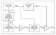
- FIG. 1shows a first embodiment of the present invention used in a polar modulated transmitter 10 .
- a polar modulated baseband controller 12provides an amplitude modulation signal V AMPLITUDE and a phase modulation signal V PHASE .
- V AMPLITUDEis provided to an AM power supply 14 through coupling circuitry 16 , which adapts V AMPLITUDE into an AM power supply input signal V AMIN .
- the AM power supplyuses V AMIN to create an AM power supply output signal V AMOUT , which provides an envelope supply voltage.
- V PHASEfeeds a phase modulation RF modulator 18 , which uses V PHASE to phase modulate an RF carrier (not shown) to create a first PM signal RF PM1 .
- An RF power amplifier driver circuit 20amplifies RF PM1 to create a second PM signal RF PM2 .
- the RF power amplifier driver circuit 20may include one or more amplifier stages.
- a PM signal amplitude modulator circuit 22receives and amplitude modulates RF PM2 using V AMOUT to create an amplitude modulated phase modulation signal RF AMPM , which provides the RF input signal to an RF power amplifier final stage 24 .
- the RF power amplifier final stage 24uses V AMOUT as its envelope supply voltage, which provides amplitude modulation of the RF input signal to create a polar modulated RF output signal RF OUT .
- the RF input signal to the RF power amplifier final stage 24is the amplitude modulated phase modulation signal RF AMPM , which was previously amplitude modulated, headroom in the RF power amplifier final stage 24 between the RF input signal and the envelope supply voltage is maintained, which allows use of large amplitude AM input signals.
- FIG. 2shows a second embodiment of the present invention, which is similar to the first embodiment of the present invention shown in FIG. 1 , except the PM signal amplitude modulator circuit 22 uses V AMIN instead of V AMOUT to create the amplitude modulated phase modulation signal RF AMPM .
- FIG. 3shows details of the RF power amplifier final stage 24 of FIG. 1 .
- An NPN transistor 26is the primary active element in the final stage 24 , and is fed the amplitude modulated phase modulation signal RF AMPM through final stage input circuitry 28 .
- V AMOUTprovides the envelope supply voltage to the collector of the NPN transistor 26 through an inductor L 1 . Since the envelope supply voltage is amplitude modulated, the NPN transistor 26 amplifies and amplitude modulates RF AMPM .
- the polar modulated RF output signal RF OUTis provided from the collector of the NPN transistor 26 through matching circuitry 30 .
- the emitter of the NPN transistor 26is connected to emitter circuitry 32 .
- the PM signal amplitude modulator circuit 22provides sufficient amplitude modulation in creating RF AMPM to prevent the base-to-collector junction of the NPN transistor 26 from becoming forward biased, even in the presence of large AM input signals. By preventing forward biasing of the base-to-collector junction of the NPN transistor 26 , proper amplification behavior is maintained.
- the NPN transistor 26may include an array of at least one bipolar NPN transistor.
- FIG. 4shows details of the PM signal amplitude modulator circuit 22 of FIG. 1 .
- An operational amplifier 34amplifies and inverts the AM power supply output signal V AMOUT .
- the gain of the operational amplifier 34is determined by two gain resistors R 1 , R 2 .
- the DC bias point of the operational amplifier 34is set by a DC reference voltage VREF.
- the amplified and inverted AM power supply output signalfeeds a current setting resistor R 3 coupled to the anode of a diode CR 1 .
- the cathode of the diode CR 1is coupled to ground.
- the amplitude modulated phase modulation signal RF AMPMis created by feeding the second PM signal RF PM2 through two coupling capacitors C 1 , C 2 , which are coupled to the anode of the diode CR 1 .
- the current setting resistor R 3provides current to the diode CR 1 inversely to the amplitude of the AM power supply output signal V AMOUT .
- the RF impedance of the diode CR 1decreases; therefore, as the amplitude of the AM power supply output signal V AMOUT decreases, the voltage across the current setting resistor R 3 increases, the current through the diode CR 1 increases, and the RF impedance of the diode CR 1 decreases, which reduces the amplitude of the amplitude modulated phase modulation signal RF AMPM .
- FIG. 5shows an application example of a large signal polar modulated RF power amplifier used in power amplifier circuitry 36 in a mobile terminal 38 .
- the basic architecture of the mobile terminal 38may include a receiver front end 40 , a radio frequency transmitter section 42 , an antenna 44 , a duplexer or switch 46 , a baseband processor 48 , a control system 50 , a frequency synthesizer 52 , and an interface 54 .
- the receiver front end 40receives information bearing radio frequency signals from one or more remote transmitters provided by a base station.
- a low noise amplifier (LNA) 56amplifies the signal.
- LNAlow noise amplifier
- a filter circuit 58minimizes broadband interference in the received signal, while downconversion and digitization circuitry 60 downconverts the filtered, received signal to an intermediate or baseband frequency signal, which is then digitized into one or more digital streams.
- the receiver front end 40typically uses one or more mixing frequencies generated by the frequency synthesizer 52 .
- the baseband processor 48processes the digitized received signal to extract the information or data bits conveyed in the received signal. This processing typically comprises demodulation, decoding, and error correction operations. As such, the baseband processor 48 is generally implemented in one or more digital signal processors (DSPs).
- DSPsdigital signal processors
- the baseband processor 48receives digitized data, which may represent voice, data, or control information, from the control system 50 , which it encodes for transmission.
- the encoded datais output to the transmitter 42 , and contains phase modulation and amplitude modulation information needed for polar modulation.
- the phase modulation informationis used by a modulator 62 to modulate a carrier signal that is at a desired transmit frequency.
- the power amplifier circuitry 36amplifies and amplitude modulates the modulated carrier signal to create a polar modulated RF signal appropriate for transmission, and delivers the amplified and modulated carrier signal to the antenna 44 through the duplexer or switch 46 .
- a usermay interact with the mobile terminal 38 via the interface 54 , which may include interface circuitry 64 associated with a microphone 66 , a speaker 68 , a keypad 70 , and a display 72 .
- the interface circuitry 64typically includes analog-to-digital converters, digital-to-analog converters, amplifiers, and the like. Additionally, it may include a voice encoder/decoder, in which case it may communicate directly with the baseband processor 48 .
- the microphone 66will typically convert audio input, such as the user's voice, into an electrical signal, which is then digitized and passed directly or indirectly to the baseband processor 48 .
- Audio information encoded in the received signalis recovered by the baseband processor 48 , and converted by the interface circuitry 64 into an analog signal suitable for driving the speaker 68 .
- the keypad 70 and display 72enable the user to interact with the mobile terminal 38 , input numbers to be dialed, address book information, or the like, as well as monitor call progress information.
Landscapes
- Engineering & Computer Science (AREA)
- Power Engineering (AREA)
- Computer Networks & Wireless Communication (AREA)
- Signal Processing (AREA)
- Amplifiers (AREA)
- Transmitters (AREA)
Abstract
Description
Claims (18)
Priority Applications (1)
| Application Number | Priority Date | Filing Date | Title |
|---|---|---|---|
| US11/456,635US7593698B1 (en) | 2006-07-11 | 2006-07-11 | Large signal polar modulated power amplifier |
Applications Claiming Priority (1)
| Application Number | Priority Date | Filing Date | Title |
|---|---|---|---|
| US11/456,635US7593698B1 (en) | 2006-07-11 | 2006-07-11 | Large signal polar modulated power amplifier |
Publications (1)
| Publication Number | Publication Date |
|---|---|
| US7593698B1true US7593698B1 (en) | 2009-09-22 |
Family
ID=41077028
Family Applications (1)
| Application Number | Title | Priority Date | Filing Date |
|---|---|---|---|
| US11/456,635Active2027-10-12US7593698B1 (en) | 2006-07-11 | 2006-07-11 | Large signal polar modulated power amplifier |
Country Status (1)
| Country | Link |
|---|---|
| US (1) | US7593698B1 (en) |
Cited By (21)
| Publication number | Priority date | Publication date | Assignee | Title |
|---|---|---|---|---|
| US20080205550A1 (en)* | 2007-02-28 | 2008-08-28 | Ahmadreza Rofougaran | Method and System for Using a Phase Locked Loop for Upconversion in a Wideband Polar Transmitter |
| US20080205560A1 (en)* | 2007-02-27 | 2008-08-28 | Ahmadreza Rofougaran | Method and system for utilizing direct digital frequency synthesis to process signals in multi-band applications |
| US20080205543A1 (en)* | 2007-02-28 | 2008-08-28 | Ahmadreza Rofougaran | Method and System for a High-Precision Frequency Generator using a Direct Digital Frequency Synthesizer for Transmitters and Receivers |
| US20080205545A1 (en)* | 2007-02-28 | 2008-08-28 | Ahmadreza Rofougaran | Method and System for Using a Phase Locked Loop for Upconversion in a Wideband Crystalless Polar Transmitter |
| US20080205549A1 (en)* | 2007-02-28 | 2008-08-28 | Ahmadreza Rofougaran | Method and System for a Wideband Polar Transmitter |
| US20080212707A1 (en)* | 2007-03-01 | 2008-09-04 | Ahmadreza Rofougaran | Method and system for a digital polar transmitter |
| US20090036072A1 (en)* | 2007-07-31 | 2009-02-05 | Ahmadreza Rofougaran | Method and system for power supply adjustment and polar modulation in an rf transmitter |
| US20090040958A1 (en)* | 2007-08-07 | 2009-02-12 | Harris Corporation | Transmitting RF signals employing both digital and analog components with a common amplifier |
| US20090153250A1 (en)* | 2007-12-12 | 2009-06-18 | Ahmadreza Rofougaran | Method and system for scaling supply, device size, and load of a power amplifier |
| US20090233644A1 (en)* | 2008-03-11 | 2009-09-17 | Matsushita Electric Industrial Co., Ltd. | Multiple carrier radio systems and methods employing polar active antenna elements |
| US7877060B1 (en) | 2006-02-06 | 2011-01-25 | Rf Micro Devices, Inc. | Fast calibration of AM/PM pre-distortion |
| US7962108B1 (en) | 2006-03-29 | 2011-06-14 | Rf Micro Devices, Inc. | Adaptive AM/PM compensation |
| US7991071B2 (en) | 2002-05-16 | 2011-08-02 | Rf Micro Devices, Inc. | AM to PM correction system for polar modulator |
| US8009762B1 (en)* | 2007-04-17 | 2011-08-30 | Rf Micro Devices, Inc. | Method for calibrating a phase distortion compensated polar modulated radio frequency transmitter |
| US20120082265A1 (en)* | 2009-06-11 | 2012-04-05 | Panasonic Corporation | Amplitude control circuit, polar modulation transmission circuit, and polar modulation method |
| US8224265B1 (en) | 2005-06-13 | 2012-07-17 | Rf Micro Devices, Inc. | Method for optimizing AM/AM and AM/PM predistortion in a mobile terminal |
| US8489042B1 (en) | 2009-10-08 | 2013-07-16 | Rf Micro Devices, Inc. | Polar feedback linearization |
| US20150295611A1 (en)* | 2014-01-16 | 2015-10-15 | Intel IP Corporation | Concurrent transmit and receive |
| DE112011105962B4 (en)* | 2011-12-16 | 2018-01-11 | Etri Electronics And Telecommunications Research Institute | Digital polar modulator for an RF power amplifier |
| CN112217481A (en)* | 2019-07-09 | 2021-01-12 | 株式会社村田制作所 | Power amplifying circuit |
| WO2025060824A1 (en)* | 2023-09-22 | 2025-03-27 | 深圳飞骧科技股份有限公司 | Power amplifier circuit and radio frequency power amplifier module |
Citations (26)
| Publication number | Priority date | Publication date | Assignee | Title |
|---|---|---|---|---|
| US5028890A (en)* | 1990-05-02 | 1991-07-02 | Hewlett-Packard Company | Voltage driven microwave amplitude modulation system |
| US5329244A (en)* | 1991-07-31 | 1994-07-12 | Nec Corporation | Linear compensating circuit |
| US5423074A (en)* | 1990-11-14 | 1995-06-06 | Ericsson Ge Mobile Communications Inc. | AM-FM transmitter power amplifier |
| US6225754B1 (en)* | 1996-10-21 | 2001-05-01 | Matsushita Electric Industrial Co., Ltd. | Operating method and operating apparatus for a high pressure discharge lamp |
| US6278328B1 (en)* | 1999-05-31 | 2001-08-21 | Mitsubishi Denki Kabushiki Kaisha | Power amplifier |
| US6295442B1 (en)* | 1998-12-07 | 2001-09-25 | Ericsson Inc. | Amplitude modulation to phase modulation cancellation method in an RF amplifier |
| US6366177B1 (en) | 2000-02-02 | 2002-04-02 | Tropian Inc. | High-efficiency power modulators |
| US6377784B2 (en) | 1999-02-09 | 2002-04-23 | Tropian, Inc. | High-efficiency modulation RF amplifier |
| US6438360B1 (en)* | 1999-07-22 | 2002-08-20 | Motorola, Inc. | Amplifier system with load control to produce an amplitude envelope |
| US20020141510A1 (en)* | 2001-03-28 | 2002-10-03 | Ashvattha Semiconductor, Inc. | Method of and apparatus for performing modulation |
| US20030157905A1 (en)* | 2002-02-18 | 2003-08-21 | Matsushita Electric Industrial Co., Ltd. | Transmitter and associated method for reducing the adjacent channel power during wireless communications |
| US6801086B1 (en) | 2002-04-03 | 2004-10-05 | Andrew Corporation | Adaptive digital pre-distortion using amplifier model that incorporates frequency-dependent non-linearities |
| US20040240583A1 (en)* | 2003-05-29 | 2004-12-02 | Rauh Michael John | Wide-bandwidth, high-dynamic-range linear amplifier for a CDMA transmitter in a wireless base station |
| US20050008373A1 (en)* | 2000-07-07 | 2005-01-13 | Nippon Telegraph And Telephone Corp. | Multi-wavelength generating method and apparatus based on flattening of optical spectrum |
| US6924711B2 (en)* | 2002-06-07 | 2005-08-02 | Utstarcom, Inc. | Multimode modulator employing a phase lock loop for wireless communications |
| US6978417B1 (en)* | 2000-05-03 | 2005-12-20 | International Business Machines Corporation | Method and system for subsetting rich media in a peer-to-peer model |
| US7010276B2 (en)* | 2001-04-11 | 2006-03-07 | Tropian, Inc. | Communications signal amplifiers having independent power control and amplitude modulation |
| US7023292B2 (en)* | 2003-12-17 | 2006-04-04 | Telefonaktiebolaget L.M. Dericsson | Polar modulation using amplitude modulated quadrature signals |
| US7038536B2 (en)* | 2001-08-29 | 2006-05-02 | Tropian, Inc. | Power supply processing for power amplifiers |
| US7158494B2 (en)* | 2001-10-22 | 2007-01-02 | Matsushita Electric Industrial Co., Ltd. | Multi-mode communications transmitter |
| US20070014382A1 (en)* | 2005-07-15 | 2007-01-18 | Nokia Corporation | Reconfigurable transmitter |
| US7227342B2 (en)* | 2003-03-21 | 2007-06-05 | Matsushita Electric Industrial Co., Ltd. | Extremely high-speed switchmode DC-DC converters |
| US20070142000A1 (en)* | 2005-12-15 | 2007-06-21 | Stefan Herzinger | Hybrid polar transmission apparatus for a radio transmission system |
| US20070298734A1 (en)* | 2006-06-04 | 2007-12-27 | Wangmyong Woo | Systems, Methods, and Apparatuses for Linear Polar Transmitters |
| US7359685B2 (en)* | 2002-11-14 | 2008-04-15 | Fraunhofer-Gesellschaft zur Förderung der Angewandten Forschung Ev | Transmitting stage |
| US7424064B2 (en)* | 2003-11-20 | 2008-09-09 | Nokia Corporation | Polar transmitter with digital to RF converter |
- 2006
- 2006-07-11USUS11/456,635patent/US7593698B1/enactiveActive
Patent Citations (26)
| Publication number | Priority date | Publication date | Assignee | Title |
|---|---|---|---|---|
| US5028890A (en)* | 1990-05-02 | 1991-07-02 | Hewlett-Packard Company | Voltage driven microwave amplitude modulation system |
| US5423074A (en)* | 1990-11-14 | 1995-06-06 | Ericsson Ge Mobile Communications Inc. | AM-FM transmitter power amplifier |
| US5329244A (en)* | 1991-07-31 | 1994-07-12 | Nec Corporation | Linear compensating circuit |
| US6225754B1 (en)* | 1996-10-21 | 2001-05-01 | Matsushita Electric Industrial Co., Ltd. | Operating method and operating apparatus for a high pressure discharge lamp |
| US6295442B1 (en)* | 1998-12-07 | 2001-09-25 | Ericsson Inc. | Amplitude modulation to phase modulation cancellation method in an RF amplifier |
| US6377784B2 (en) | 1999-02-09 | 2002-04-23 | Tropian, Inc. | High-efficiency modulation RF amplifier |
| US6278328B1 (en)* | 1999-05-31 | 2001-08-21 | Mitsubishi Denki Kabushiki Kaisha | Power amplifier |
| US6438360B1 (en)* | 1999-07-22 | 2002-08-20 | Motorola, Inc. | Amplifier system with load control to produce an amplitude envelope |
| US6366177B1 (en) | 2000-02-02 | 2002-04-02 | Tropian Inc. | High-efficiency power modulators |
| US6978417B1 (en)* | 2000-05-03 | 2005-12-20 | International Business Machines Corporation | Method and system for subsetting rich media in a peer-to-peer model |
| US20050008373A1 (en)* | 2000-07-07 | 2005-01-13 | Nippon Telegraph And Telephone Corp. | Multi-wavelength generating method and apparatus based on flattening of optical spectrum |
| US20020141510A1 (en)* | 2001-03-28 | 2002-10-03 | Ashvattha Semiconductor, Inc. | Method of and apparatus for performing modulation |
| US7010276B2 (en)* | 2001-04-11 | 2006-03-07 | Tropian, Inc. | Communications signal amplifiers having independent power control and amplitude modulation |
| US7038536B2 (en)* | 2001-08-29 | 2006-05-02 | Tropian, Inc. | Power supply processing for power amplifiers |
| US7158494B2 (en)* | 2001-10-22 | 2007-01-02 | Matsushita Electric Industrial Co., Ltd. | Multi-mode communications transmitter |
| US20030157905A1 (en)* | 2002-02-18 | 2003-08-21 | Matsushita Electric Industrial Co., Ltd. | Transmitter and associated method for reducing the adjacent channel power during wireless communications |
| US6801086B1 (en) | 2002-04-03 | 2004-10-05 | Andrew Corporation | Adaptive digital pre-distortion using amplifier model that incorporates frequency-dependent non-linearities |
| US6924711B2 (en)* | 2002-06-07 | 2005-08-02 | Utstarcom, Inc. | Multimode modulator employing a phase lock loop for wireless communications |
| US7359685B2 (en)* | 2002-11-14 | 2008-04-15 | Fraunhofer-Gesellschaft zur Förderung der Angewandten Forschung Ev | Transmitting stage |
| US7227342B2 (en)* | 2003-03-21 | 2007-06-05 | Matsushita Electric Industrial Co., Ltd. | Extremely high-speed switchmode DC-DC converters |
| US20040240583A1 (en)* | 2003-05-29 | 2004-12-02 | Rauh Michael John | Wide-bandwidth, high-dynamic-range linear amplifier for a CDMA transmitter in a wireless base station |
| US7424064B2 (en)* | 2003-11-20 | 2008-09-09 | Nokia Corporation | Polar transmitter with digital to RF converter |
| US7023292B2 (en)* | 2003-12-17 | 2006-04-04 | Telefonaktiebolaget L.M. Dericsson | Polar modulation using amplitude modulated quadrature signals |
| US20070014382A1 (en)* | 2005-07-15 | 2007-01-18 | Nokia Corporation | Reconfigurable transmitter |
| US20070142000A1 (en)* | 2005-12-15 | 2007-06-21 | Stefan Herzinger | Hybrid polar transmission apparatus for a radio transmission system |
| US20070298734A1 (en)* | 2006-06-04 | 2007-12-27 | Wangmyong Woo | Systems, Methods, and Apparatuses for Linear Polar Transmitters |
Cited By (30)
| Publication number | Priority date | Publication date | Assignee | Title |
|---|---|---|---|---|
| US7991071B2 (en) | 2002-05-16 | 2011-08-02 | Rf Micro Devices, Inc. | AM to PM correction system for polar modulator |
| US8224265B1 (en) | 2005-06-13 | 2012-07-17 | Rf Micro Devices, Inc. | Method for optimizing AM/AM and AM/PM predistortion in a mobile terminal |
| US7877060B1 (en) | 2006-02-06 | 2011-01-25 | Rf Micro Devices, Inc. | Fast calibration of AM/PM pre-distortion |
| US7962108B1 (en) | 2006-03-29 | 2011-06-14 | Rf Micro Devices, Inc. | Adaptive AM/PM compensation |
| US8284822B2 (en)* | 2007-02-27 | 2012-10-09 | Broadcom Corporation | Method and system for utilizing direct digital frequency synthesis to process signals in multi-band applications |
| US20080205560A1 (en)* | 2007-02-27 | 2008-08-28 | Ahmadreza Rofougaran | Method and system for utilizing direct digital frequency synthesis to process signals in multi-band applications |
| US20080205545A1 (en)* | 2007-02-28 | 2008-08-28 | Ahmadreza Rofougaran | Method and System for Using a Phase Locked Loop for Upconversion in a Wideband Crystalless Polar Transmitter |
| US20080205550A1 (en)* | 2007-02-28 | 2008-08-28 | Ahmadreza Rofougaran | Method and System for Using a Phase Locked Loop for Upconversion in a Wideband Polar Transmitter |
| US8036308B2 (en)* | 2007-02-28 | 2011-10-11 | Broadcom Corporation | Method and system for a wideband polar transmitter |
| US20080205543A1 (en)* | 2007-02-28 | 2008-08-28 | Ahmadreza Rofougaran | Method and System for a High-Precision Frequency Generator using a Direct Digital Frequency Synthesizer for Transmitters and Receivers |
| US7826550B2 (en)* | 2007-02-28 | 2010-11-02 | Broadcom Corp. | Method and system for a high-precision frequency generator using a direct digital frequency synthesizer for transmitters and receivers |
| US20080205549A1 (en)* | 2007-02-28 | 2008-08-28 | Ahmadreza Rofougaran | Method and System for a Wideband Polar Transmitter |
| US8116387B2 (en)* | 2007-03-01 | 2012-02-14 | Broadcom Corporation | Method and system for a digital polar transmitter |
| US20080212707A1 (en)* | 2007-03-01 | 2008-09-04 | Ahmadreza Rofougaran | Method and system for a digital polar transmitter |
| US8009762B1 (en)* | 2007-04-17 | 2011-08-30 | Rf Micro Devices, Inc. | Method for calibrating a phase distortion compensated polar modulated radio frequency transmitter |
| US20090036072A1 (en)* | 2007-07-31 | 2009-02-05 | Ahmadreza Rofougaran | Method and system for power supply adjustment and polar modulation in an rf transmitter |
| US8155604B2 (en)* | 2007-07-31 | 2012-04-10 | Broadcom Corporation | Method and system for power supply adjustment and polar modulation in an RF transmitter |
| US20090040958A1 (en)* | 2007-08-07 | 2009-02-12 | Harris Corporation | Transmitting RF signals employing both digital and analog components with a common amplifier |
| US7929926B2 (en)* | 2007-08-07 | 2011-04-19 | Harris Corporation | Transmitting RF signals employing both digital and analog components with a common amplifier |
| US20090153250A1 (en)* | 2007-12-12 | 2009-06-18 | Ahmadreza Rofougaran | Method and system for scaling supply, device size, and load of a power amplifier |
| US20090233644A1 (en)* | 2008-03-11 | 2009-09-17 | Matsushita Electric Industrial Co., Ltd. | Multiple carrier radio systems and methods employing polar active antenna elements |
| US8514969B2 (en)* | 2009-06-11 | 2013-08-20 | Panasonic Corporation | Amplitude control circuit, polar modulation transmission circuit, and polar modulation method |
| US20120082265A1 (en)* | 2009-06-11 | 2012-04-05 | Panasonic Corporation | Amplitude control circuit, polar modulation transmission circuit, and polar modulation method |
| US8489042B1 (en) | 2009-10-08 | 2013-07-16 | Rf Micro Devices, Inc. | Polar feedback linearization |
| DE112011105962B4 (en)* | 2011-12-16 | 2018-01-11 | Etri Electronics And Telecommunications Research Institute | Digital polar modulator for an RF power amplifier |
| US20150295611A1 (en)* | 2014-01-16 | 2015-10-15 | Intel IP Corporation | Concurrent transmit and receive |
| US9544002B2 (en)* | 2014-01-16 | 2017-01-10 | Intel IP Corporation | Concurrent transmit and receive |
| CN112217481A (en)* | 2019-07-09 | 2021-01-12 | 株式会社村田制作所 | Power amplifying circuit |
| US12199573B2 (en)* | 2019-07-09 | 2025-01-14 | Murata Manufacturing Co., Ltd. | Power amplifier circuit |
| WO2025060824A1 (en)* | 2023-09-22 | 2025-03-27 | 深圳飞骧科技股份有限公司 | Power amplifier circuit and radio frequency power amplifier module |
Similar Documents
| Publication | Publication Date | Title |
|---|---|---|
| US7593698B1 (en) | Large signal polar modulated power amplifier | |
| US7884681B1 (en) | Radio frequency power amplifier improvements using pre-distortion of an amplitude modulation power supply | |
| US7315211B1 (en) | Sliding bias controller for use with radio frequency power amplifiers | |
| US7471155B1 (en) | Cancelling switching power supply ripple from a radio frequency signal | |
| US7193459B1 (en) | Power amplifier control technique for enhanced efficiency | |
| US7190935B2 (en) | Amplifier power detection circuitry | |
| US7474158B1 (en) | Dynamic match low noise amplifier with reduced current consumption in low gain mode | |
| US6839549B2 (en) | System and method of RF power amplification | |
| US7164893B2 (en) | Method and apparatus for optimizing supply modulation in a transmitter | |
| KR101793733B1 (en) | Apparatus and method for calibration of supply modualtion in transmitter | |
| US7333778B2 (en) | System and method for current-mode amplitude modulation | |
| US7459988B1 (en) | High linearity wide dynamic range radio frequency antenna switch | |
| US9337787B2 (en) | Power amplifier with improved low bias mode linearity | |
| US7772927B1 (en) | Active bias Darlington amplifier | |
| US6785521B2 (en) | System and method for current-mode amplitude modulation | |
| KR101746107B1 (en) | Adaptive Power Amplifier and RF Transmitter Including Same | |
| KR100813660B1 (en) | Power Amplifier Circuit for Peak Envelope Modulation of High Frequency Signals | |
| US6680652B2 (en) | Load switching for transmissions with different peak-to-average power ratios | |
| US8884703B2 (en) | VRAMP limiting using resistors | |
| US8009762B1 (en) | Method for calibrating a phase distortion compensated polar modulated radio frequency transmitter | |
| US7616055B2 (en) | Transmitter apparatus with extended gain control | |
| US20130027130A1 (en) | Collector boost | |
| US7741912B1 (en) | Varying amplifier bias parameters to meet radio frequency (RF) communications requirements | |
| US7440734B1 (en) | Active quadrature radio frequency power detector | |
| US7454179B1 (en) | Radio frequency power detector and decision circuit used with DC supply voltage controlled power amplifiers |
Legal Events
| Date | Code | Title | Description |
|---|---|---|---|
| AS | Assignment | Owner name:RF MICRO DEVICES, INC., NORTH CAROLINA Free format text:ASSIGNMENT OF ASSIGNORS INTEREST;ASSIGNORS:JOHNSON, JACKIE;BOSLEY, RYAN;ZYBURA, MICHAEL F.;REEL/FRAME:017912/0799 Effective date:20060705 | |
| STCF | Information on status: patent grant | Free format text:PATENTED CASE | |
| FPAY | Fee payment | Year of fee payment:4 | |
| AS | Assignment | Owner name:BANK OF AMERICA, N.A., AS ADMINISTRATIVE AGENT, TE Free format text:NOTICE OF GRANT OF SECURITY INTEREST IN PATENTS;ASSIGNOR:RF MICRO DEVICES, INC.;REEL/FRAME:030045/0831 Effective date:20130319 | |
| AS | Assignment | Owner name:RF MICRO DEVICES, INC., NORTH CAROLINA Free format text:TERMINATION AND RELEASE OF SECURITY INTEREST IN PATENTS (RECORDED 3/19/13 AT REEL/FRAME 030045/0831);ASSIGNOR:BANK OF AMERICA, N.A., AS ADMINISTRATIVE AGENT;REEL/FRAME:035334/0363 Effective date:20150326 | |
| AS | Assignment | Owner name:QORVO US, INC., NORTH CAROLINA Free format text:MERGER;ASSIGNOR:RF MICRO DEVICES, INC.;REEL/FRAME:039196/0941 Effective date:20160330 | |
| REMI | Maintenance fee reminder mailed | ||
| FEPP | Fee payment procedure | Free format text:7.5 YR SURCHARGE - LATE PMT W/IN 6 MO, LARGE ENTITY (ORIGINAL EVENT CODE: M1555) | |
| MAFP | Maintenance fee payment | Free format text:PAYMENT OF MAINTENANCE FEE, 8TH YEAR, LARGE ENTITY (ORIGINAL EVENT CODE: M1552) Year of fee payment:8 | |
| MAFP | Maintenance fee payment | Free format text:PAYMENT OF MAINTENANCE FEE, 12TH YEAR, LARGE ENTITY (ORIGINAL EVENT CODE: M1553); ENTITY STATUS OF PATENT OWNER: LARGE ENTITY Year of fee payment:12 |