US7593429B2 - System and method for time synchronizing nodes in an automotive network using input capture - Google Patents
System and method for time synchronizing nodes in an automotive network using input captureDownload PDFInfo
- Publication number
- US7593429B2 US7593429B2US11/014,936US1493604AUS7593429B2US 7593429 B2US7593429 B2US 7593429B2US 1493604 AUS1493604 AUS 1493604AUS 7593429 B2US7593429 B2US 7593429B2
- Authority
- US
- United States
- Prior art keywords
- node
- offset
- timestamp
- synchronization
- switch fabric
- Prior art date
- Legal status (The legal status is an assumption and is not a legal conclusion. Google has not performed a legal analysis and makes no representation as to the accuracy of the status listed.)
- Active, expires
Links
- 238000000034methodMethods0.000titleclaimsabstractdescription38
- 238000004891communicationMethods0.000claimsabstractdescription45
- 239000004744fabricSubstances0.000claimsabstractdescription38
- 230000005540biological transmissionEffects0.000claimsabstractdescription15
- 239000003999initiatorSubstances0.000claimsdescription13
- 230000000977initiatory effectEffects0.000claimsdescription4
- 230000006870functionEffects0.000abstractdescription9
- 230000007704transitionEffects0.000description11
- 230000008569processEffects0.000description5
- 238000010586diagramMethods0.000description4
- 230000001360synchronised effectEffects0.000description4
- 230000001133accelerationEffects0.000description3
- 230000000694effectsEffects0.000description3
- 230000008901benefitEffects0.000description2
- 230000008878couplingEffects0.000description2
- 238000010168coupling processMethods0.000description2
- 238000005859coupling reactionMethods0.000description2
- 230000007246mechanismEffects0.000description2
- 238000012986modificationMethods0.000description2
- 230000004048modificationEffects0.000description2
- 230000003287optical effectEffects0.000description2
- 238000012546transferMethods0.000description2
- 230000004913activationEffects0.000description1
- 230000003044adaptive effectEffects0.000description1
- QVGXLLKOCUKJST-UHFFFAOYSA-Natomic oxygenChemical compound[O]QVGXLLKOCUKJST-UHFFFAOYSA-N0.000description1
- 239000000919ceramicSubstances0.000description1
- 239000013078crystalSubstances0.000description1
- 230000002401inhibitory effectEffects0.000description1
- 239000013307optical fiberSubstances0.000description1
- 229910052760oxygenInorganic materials0.000description1
- 239000001301oxygenSubstances0.000description1
- 238000012545processingMethods0.000description1
- 239000000725suspensionSubstances0.000description1
Images


Classifications
- H—ELECTRICITY
- H04—ELECTRIC COMMUNICATION TECHNIQUE
- H04J—MULTIPLEX COMMUNICATION
- H04J3/00—Time-division multiplex systems
- H04J3/02—Details
- H04J3/06—Synchronising arrangements
- H04J3/0635—Clock or time synchronisation in a network
- H04J3/0682—Clock or time synchronisation in a network by delay compensation, e.g. by compensation of propagation delay or variations thereof, by ranging
- H—ELECTRICITY
- H04—ELECTRIC COMMUNICATION TECHNIQUE
- H04J—MULTIPLEX COMMUNICATION
- H04J3/00—Time-division multiplex systems
- H04J3/02—Details
- H04J3/06—Synchronising arrangements
- H04J3/0635—Clock or time synchronisation in a network
- H04J3/0638—Clock or time synchronisation among nodes; Internode synchronisation
- H04J3/0658—Clock or time synchronisation among packet nodes
- H04J3/0661—Clock or time synchronisation among packet nodes using timestamps
- H04J3/0664—Clock or time synchronisation among packet nodes using timestamps unidirectional timestamps
- H—ELECTRICITY
- H04—ELECTRIC COMMUNICATION TECHNIQUE
- H04L—TRANSMISSION OF DIGITAL INFORMATION, e.g. TELEGRAPHIC COMMUNICATION
- H04L12/00—Data switching networks
- H04L12/28—Data switching networks characterised by path configuration, e.g. LAN [Local Area Networks] or WAN [Wide Area Networks]
- H04L12/40—Bus networks
- H04L12/403—Bus networks with centralised control, e.g. polling
Definitions
- this difficultytake for example the need to capture data from multiple sensors at the same time. For example, it may be necessary to communicate various control parameters from a number of engine sensors to an engine controller so that it may then issue commands for the control of the engine.
- the engine controllerreceives data from several oxygen sensors, the crankshaft position sensor and potentially other sensors.
- the datamust arrive to the engine controller in a coordinated manner or have a reliable time indication. Unless each of the sensors are time synchronized, there is no way to accurately time stamp the data packets or to effectively communicate them to the engine controller in a coordinated manner.
- FIG. 2is a graphic illustration of an embodiment of a vehicle switch fabric network according to the invention.
- FIG. 3is a graphic illustration of a portion of the vehicle active network illustrating the exchange of messages between two nodes
- FIGS. 4A-4Care flow diagrams illustrating one embodiment of a synchronization dialogue between two nodes
- FIG. 5is a graphic illustration of an offset table that may be stored in a node of the vehicle active network
- FIG. 6is a graphic illustration of a routing table that may be stored in a node of the vehicle active network.
- each node of the switch fabricmay include a processor, a memory, a clock, a transceiver, and an input capture.
- the memoryis adapted to store and retain timer offsets associated with communication links with neighboring nodes.
- the transceiveris adapted to transmit and receive synchronization messages between the node and neighboring nodes.
- the input captureis adapted to capture timestamps associated with the transmission of synchronization messages.
- the processoris configured to compute the timer offsets associated with the communication links with neighboring nodes based on the captured timestamps by the input capture function.
- the computed offsetsmay then be broadcast and stored by the nodes for subsequent use in time synchronizing data packets through the switch fabric network.
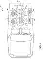
- FIG. 1illustrates a vehicle 20 including a network 22 to which various vehicle devices 24 a - d are coupled via respective interfaces 26 a - d .
- the vehicle devices 24 a - dmay be sensors, actuators, and processors used in connection with various vehicle functional systems and sub-systems, such as, but not limited to, diagnostics, control-by-wire applications for throttle, braking and steering control, adaptive suspension, power accessory control, communications, entertainment, and the like.
- the interfaces 26 a - dare any suitable interface for coupling the particular vehicle device 24 a - d to the network 22 , and may be wire, optical, wireless or combinations thereof.
- the vehicle device 24 a - dis particularly adapted to provide one or more functions associated with the vehicle 20 .
- These vehicle devices 24 a - dmay be data producing, such as a sensor, data consuming, such as an actuator, or processing, which both produces and consumes data.
- an actuatortypically a data-consuming device, may also produce data, for example where the actuator produces data indicating it has achieved the instructed state, or a sensor may consume data, for example, where it is provided instructions for the manner of function.
- the network 22may include a switch fabric 28 defining a plurality of communication paths between the vehicle devices 24 a - d .
- the communication pathspermit multiple simultaneous peer-to-peer, one-to-many, many-to-many, etc. communications between the vehicle devices 24 a - d .
- data exchangedfor example, between devices 24 a and 24 d may utilize any available path or paths between the vehicle devices 24 a , 24 d .
- a single path through the switch fabric 28may carry all of a single data communication between one vehicle device 24 a and another vehicle device 24 d , or several communication paths may carry portions of the data communication.
- Subsequent communicationsmay use the same path or other paths as dictated by the then state of the network 22 .
- Thisprovides reliability and speed advantages over bus architectures that provide single communication paths between devices, and hence are subject to failure with failure of the single path.
- communications between other of the devices 24 b , 24 cmay occur simultaneously using the communication paths within the switch fabric 28 .
- the network 22may comply with transmission control protocol/Internet (TCP/IP), asynchronous transfer mode (ATM), Infiniband, RapidIO, or other packet data protocols. As such, the network 22 utilizes data packets, having fixed or variable length, defined by the applicable protocol. For example, if the network 22 uses asynchronous transfer mode (ATM) communication protocol, ATM standard data cells are used.
- TCP/IPtransmission control protocol/Internet
- ATMasynchronous transfer mode
- ATMasynchronous transfer mode
- the vehicle devices 24 a - dneed not be discrete devices. Instead, the devices may be systems or subsystems of the vehicle and may include one or more legacy communication media, i.e., legacy bus architectures such as the Controller Area Network (CAN) protocol, the SAE J1850 Communication Standard, the Local Interconnect Network (LIN) protocol, the FLEXRAY Communications System Standard, Media Oriented Systems Transport or MOST Protocol, or similar bus structures.
- legacy bus architecturessuch as the Controller Area Network (CAN) protocol, the SAE J1850 Communication Standard, the Local Interconnect Network (LIN) protocol, the FLEXRAY Communications System Standard, Media Oriented Systems Transport or MOST Protocol, or similar bus structures.
- the respective interface 26 a - dmay be configured as a proxy or gateway to permit communication between the network 22 and the legacy device.
- an active network 22in accordance with one embodiment of the present invention includes a switch fabric 28 of nodes 30 a - h that communicatively couple a plurality of devices 24 a - d via respective interfaces 26 a - d .
- Connection media 32interconnects the nodes 30 a - h .
- the connection media 32may be bounded media, such as wire or optical fiber, unbounded media, such as free optical or radio frequency, or combinations thereof.
- the term nodeis used broadly in connection with the definition of the switch fabric 28 to include any number of intelligent structures for communicating data packets within the network 22 without an arbiter or other network controller and may include: switches, intelligent switches, routers, bridges, gateways and the like. Data is thus carried through the network 22 in data packet form guided by the nodes 30 a - h.
- a route 34defines a communication path from device 24 a to device 24 d . If there is a disruption along the route 34 inhibiting communication of the data packets from the device 24 a to the device 24 d , for example, if one or more nodes are at capacity or have become disabled or there is a disruption in the connection media joining the nodes along route 34 , a new route, illustrated as route 36 , can be used.
- the route 36may be dynamically generated or previously defined as a possible communication path, to ensure the communication between device 24 a and device 24 d.
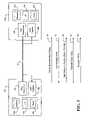
- FIG. 3illustrates a portion of the network 22 that includes a switch fabric 28 of nodes, including a first node 30 a and a second node 30 b .
- Connection media 32interconnects the first node 30 a to the second node 30 b.
- the first node 30 a and the second node 30 bmay include a microprocessor 40 a,b , a memory 42 a,b , a clock 44 a,b , a data transceiver 46 a,b to transmit and send data, and an input capture 48 a,b function.
- the microprocessor 40 a,bincludes a suitable control program for effecting the operation of the node 30 a,b for coupling inputs and outputs in order to transmit data within the network 22 .
- the microprocessor 40 a,bmay be configured to effect the operation of the synchronization dialogue in conjunction with the data transceiver 46 a,b and the input capture 48 a,b , as will be explained in further detail below.
- FIG. 3also illustrates, at a high level, one embodiment of the present invention for generating and providing synchronization information within the network 22 .
- the processbegins by the first node 30 a initiating a synchronization dialogue with the second node 30 b (arrow 50 ).
- the synchronization dialoguewill prompt the input captures 48 a,b on each node to arm.
- the second node 30 bwill respond with an acknowledgement ready message that it is ready to proceed with the synchronization dialogue (arrow 52 ).
- the first node 30 awill then send a reference synchronization message to the second node 30 b (arrow 54 ).
- the input capture 48 a,b mechanisms on each node 30 a,bwill respectively capture a timestamp that will represent the time that the synchronization message left the first node 30 and a timestamp that will represent the time that the synchronization message was received at the second node 30 b .
- the respective timestamps at each node 30 a,bare shared with each other (arrow 56 ).
- Each node 30 a,bwill then calculate a timer offset value between the two nodes and store the offset value in an offset table or database. Later, each node 30 a,b may broadcast the timer offset values that it calculated with neighboring other nodes to the entire network 22 (arrow 58 ).
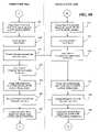
- FIGS. 4A-4Cfurther explains, at a more detailed level, one embodiment of the present invention for providing synchronization information within the network 22 .
- Synchronizationin this case is a process used by the nodes to calculate the relative clock offset between themselves and other neighboring nodes in the network 22 .
- the flow diagrams in FIGS. 4A-4Ccontain further descriptions of one embodiment for implementing the functions to calculate neighboring offsets by a node. For purposes of illustration, these diagrams represent a synchronization dialogue between the first node 30 a and the second node 30 b.
- the first node 30 a and the second node 30 bmay operate within a plurality of states and roles.
- the rolesare defined as an initiator and a receiver.
- the nodemay function differently depending on the state of the node. This allows the nodes to have a common software platform but perform different functions and roles during the synchronization dialogue process.
- the first node 30 a and the second node 30 bupon startup and during normal operation of the network 22 , the first node 30 a and the second node 30 b will enter and remain in a state called SYNC_MODE_INACTIVE.
- a nodesuch as the first node 30 a
- a neighboring nodesuch as the second node 30 b
- the nodewill exit the SYNC_MODE_INACTIVE state and begin traversing through a series of states that will walk the node through the synchronization dialogue process.
- a nodeWhen a node exits the SYNC_MODE_INACTIVE state, all outgoing messages not related to synchronization are held in an outgoing software buffer and not transmitted until the node re-enters the SYNC_MODE_INACTIVE state. As shown in box 102 of FIG. 4A , in one embodiment where a node wants to be an initiator (such as the first node 30 a ), the node may enter a SYNC_MODE_NOW state.
- the first node 30 aWhen the first node 30 a is in the SYNC_MODE_PENDING state (and designated as the initiator), it may then perform a series of tasks including transmitting a message to the neighboring second node 30 b . This is shown in box 108 of FIG. 4A where the first node 30 a transmits an initial synchronization message (discovery_sync_initiate) to the second node 30 b .
- the initial synchronization messagemay include fields such as a priority of the message and an identification of the first node 30 a .
- the first node 30 aAfter transmitting the initial synchronization message to the second node 30 b , the first node 30 a may then transition from the SYNC_MODE_PENDING state to the SYNC_MODE_READY state as shown in box 110 .
- the second node 30 bwill receive the initial synchronization message from the first node 30 a .
- the second node 30 bwill then exit the SYNC_MODE_INACTIVE state and enter the SYNC_MODE_PENDING state as shown in box 114 .
- the second node 30 bwill then check to see if its role had been previously set to an initiator. Since the second node 30 b did not transition through the SYNC_MODE_NOW state (like the first node 30 a described above), the second node 30 b will default to set its role to a receiver.
- the second node 30 bmay then transition from the SYNC_MODE_PENDING state to the SYNC_MODE_READY state as shown in box 118 .
- the second node 30 bWhen the second node 30 b is in the SYNC_MODE_READY state (and designated as the receiver), it may then perform a series tasks including transmitting a message to the initiating first node 30 a . This is shown in box 120 of FIG. 4A where the second node 30 b transmits an acknowledge ready message (discovery_sync_ready) to the first node 30 a . After transmitting the acknowledge ready message to the first node 30 a , the second node 30 b may then transition from the SYNC_MODE_READY state to the SYNC_MODE_ARMED state as shown in box 122 ( FIG. 4B ).
- the first node 30 awill receive the acknowledge ready message from the second node 30 b .
- the first node 30 amay then exit the SYNC_MODE_READY state and enter the SYNC_MODE_ARMED state as shown in box 126 .
- the nodeswill arm their respective input captures 48 a,b (the input captures are shown in FIG. 3 ). This will enable the nodes to capture a timestamp associated with the transmission of a reference synchronization message over the communication link 32 , as explained further below.
- the first node 30 aWhen the first node 30 a is in the SYNC_MODE_ARMED state (and designated as the initiator), it may then perform a series of tasks including transmitting a reference synchronization message to the neighboring second node 30 b . This is shown in box 132 of FIG. 4B where the first node 30 a transmits a reference synchronization message (discovery_sync) to the second node 30 b .
- the first node 30 awill store a value of a timestamp from its clock 44 a in memory 42 a (the input capture, clock, and memory are shown in FIG. 3 ). After storing the timestamp value in memory 42 a , the first node 30 a may then transition from the SYNC_MODE_ARMED state to the SYNC_MODE_POST state as shown in box 136 .
- the input capture 48 b of the second node 30 bwill store a value of a timestamp from its clock 44 b in memory 42 b .
- the capturemay be on the edge of the bus transition when the message is sent.
- the second node 30 bmay then transition from the SYNC_MODE_ARMED state to the SYNC_MODE_POST state as shown in box 142 .
- the second node 30 bWhen the second node 30 b is in the SYNC_MODE_POST state (and designated as the receiver), it may then perform a series of tasks including transmitting a synchronization post message to the initiating first node 30 a . This is shown in box 144 of FIG. 4B where the second node 30 b transmits a synchronization post message (discovery_sync_post) to the first node 30 a .
- the synchronization post messagemay include fields such as the timestamp value captured in memory 42 b associated with the transmission of the reference synchronization message.
- the second node 30 bAfter transmitting the synchronization post message to the first node 30 a , the second node 30 b may then transition from the SYNC_MODE_POST state to the SYNC_MODE_COMPLETE state as shown in box 146 .
- the first node 30 awill receive the synchronization post message from the second node 30 b .
- the first node 30 amay then exit the SYNC_MODE_POST state and enter the SYNC_MODE_COMPLETE state as shown in box 150 .
- the first node 30 amay then perform a series of tasks including computing an offset value and storing the offset value in an offset table in its memory 42 a .
- the first node 30 amay then perform a series of tasks including computing an offset value and storing the offset value in an offset table in its memory 42 a .
- the first node 30 amay compute the offset value based on the difference in time between the input capture value stored in its memory with the input capture value received from the second node 30 b in the synchronization post message. The first node 30 a may then store the computed offset in its memory 42 a as illustrated in box 154 .
- the first node 30 amay then transmit a synchronization complete message to the neighboring second node 30 b . This is shown in box 156 of FIG. 4C where the first node 30 a transmits a synchronization complete message (discovery_sync_complete) to the second node 30 b .
- the synchronization complete messagemay include fields such as the timestamp value stored in memory 42 a associated with the transmission of the reference synchronization message.
- the synchronization complete messagemay include the offset value computed by the first node 30 a .
- the first node 30 amay then reset all variables and transition from the SYNC_MODE_COMPLETE state to the SYNC_MODE_INACTIVE state as shown inbox 158 .
- the second node 30 bwill receive the synchronization complete message from the first node 30 a . If the synchronization complete message includes the timestamp value associated with the transmission of the reference synchronization message, then the second node 30 b may then perform additional tasks such as computing an offset value and storing the offset value in an offset table in its memory 42 b . With reference to box 162 in FIG. 4C , the second node 30 b may compute the offset value based on the difference in time between the input capture value stored in its memory with the input capture value received from the first node 30 a in the synchronization complete message. The second node 30 b may then store the computed offset in its memory 42 b as illustrated in box 164 .
- the second node 30 bmay then reset all variables and transition from the SYNC_MODE_COMPLETE state to the SYNC_MODE_INACTIVE state as shown in box 166 .
- the first node 30 amay then proceed to do a similar process with any other immediate neighboring nodes.
- the first node 30 awill store in its memory each computed offset with its immediate neighboring nodes.
- the first node 30 amay then further be configured to broadcast its stored offsets with each node 30 b - h in the network 22 .
- Each node in the network 22may then retain the timer offsets discovered by other nodes in the network 22 .
- each node 30 a - hmay maintain an offset table 70 in memory that represents the offsets that it has computed on its own as well as any offsets that it has received from other nodes.
- a nodemay further compute or calculate a clock offset between itself and any other node on the network 22 . As shown in FIG. 6 , this can be done by summing the individual offsets of node segments stored in its offset table 70 along a particular communication path. For instance, referring to FIG. 2 , if node 30 a desires to know the timing offset between node 30 a and 30 g (along path 34 ), the node will use the offsets computed and received between the communication links of 30 a - 30 b , 30 b - 30 c , and 30 c - 30 g.
- the nodes 30 a - hmay be configured to infer or determine an acceleration or drift rate of remote clocks over time.
- the acceleration or drift ratemay be computed by determining the difference between computed or received offsets over the difference in time between synchronization dialogs.
- Using inferred acceleration and drifts of clockscan improve accuracy between synchronization dialogues. It also allows the system to use less accurate crystals or ceramic resonators to reduce costs. It further allows the system to wait for longer periods between synchronization dialogues.
Landscapes
- Engineering & Computer Science (AREA)
- Computer Networks & Wireless Communication (AREA)
- Signal Processing (AREA)
- Mobile Radio Communication Systems (AREA)
- Small-Scale Networks (AREA)
Abstract
Description
Claims (22)
Priority Applications (2)
| Application Number | Priority Date | Filing Date | Title |
|---|---|---|---|
| US11/014,936US7593429B2 (en) | 2004-10-14 | 2004-12-17 | System and method for time synchronizing nodes in an automotive network using input capture |
| PCT/US2005/034863WO2006044139A2 (en) | 2004-10-14 | 2005-09-29 | System and method for time synchronizing nodes in an automotive network using input capture |
Applications Claiming Priority (3)
| Application Number | Priority Date | Filing Date | Title |
|---|---|---|---|
| US61876904P | 2004-10-14 | 2004-10-14 | |
| US61876804P | 2004-10-14 | 2004-10-14 | |
| US11/014,936US7593429B2 (en) | 2004-10-14 | 2004-12-17 | System and method for time synchronizing nodes in an automotive network using input capture |
Publications (2)
| Publication Number | Publication Date |
|---|---|
| US20060083264A1 US20060083264A1 (en) | 2006-04-20 |
| US7593429B2true US7593429B2 (en) | 2009-09-22 |
Family
ID=36180706
Family Applications (1)
| Application Number | Title | Priority Date | Filing Date |
|---|---|---|---|
| US11/014,936Active2027-12-06US7593429B2 (en) | 2004-10-14 | 2004-12-17 | System and method for time synchronizing nodes in an automotive network using input capture |
Country Status (1)
| Country | Link |
|---|---|
| US (1) | US7593429B2 (en) |
Cited By (2)
| Publication number | Priority date | Publication date | Assignee | Title |
|---|---|---|---|---|
| US20080195260A1 (en)* | 2004-12-10 | 2008-08-14 | Sumitomo Wiring Systems, Ltd. | Communication Control Apparatus |
| US20100153345A1 (en)* | 2008-12-12 | 2010-06-17 | Thilo-Alexander Ginkel | Cluster-Based Business Process Management Through Eager Displacement And On-Demand Recovery |
Families Citing this family (20)
| Publication number | Priority date | Publication date | Assignee | Title |
|---|---|---|---|---|
| US20060083172A1 (en)* | 2004-10-14 | 2006-04-20 | Jordan Patrick D | System and method for evaluating the performance of an automotive switch fabric network |
| US7593344B2 (en)* | 2004-10-14 | 2009-09-22 | Temic Automotive Of North America, Inc. | System and method for reprogramming nodes in an automotive switch fabric network |
| US7623552B2 (en)* | 2004-10-14 | 2009-11-24 | Temic Automotive Of North America, Inc. | System and method for time synchronizing nodes in an automotive network using input capture |
| US7599377B2 (en)* | 2004-10-15 | 2009-10-06 | Temic Automotive Of North America, Inc. | System and method for tunneling standard bus protocol messages through an automotive switch fabric network |
| US7613190B2 (en)* | 2004-10-18 | 2009-11-03 | Temic Automotive Of North America, Inc. | System and method for streaming sequential data through an automotive switch fabric |
| US7809131B1 (en)* | 2004-12-23 | 2010-10-05 | Arcsight, Inc. | Adjusting sensor time in a network security system |
| US7733841B2 (en)* | 2005-05-10 | 2010-06-08 | Continental Automotive Systems, Inc. | Vehicle network with time slotted access and method |
| JP2007241726A (en)* | 2006-03-09 | 2007-09-20 | Denso Corp | Driving support system, transmitter and receiver |
| US20080046142A1 (en)* | 2006-06-29 | 2008-02-21 | Motorola, Inc. | Layered architecture supports distributed failover for applications |
| EP2122926B1 (en)* | 2006-12-14 | 2012-04-04 | Bayerische Motoren Werke Aktiengesellschaft | Method of setting up a controller network in a vehicle, corresponding data bus system and computer programm product |
| CN100466584C (en)* | 2007-04-03 | 2009-03-04 | 中兴通讯股份有限公司 | Processing method of ring network protection |
| US9697159B2 (en)* | 2011-12-27 | 2017-07-04 | Intel Corporation | Multi-protocol I/O interconnect time synchronization |
| CN103685079A (en)* | 2014-01-02 | 2014-03-26 | 武汉迈威实达软件有限公司 | Self-adaptive Ethernet single-loop network algorithm |
| US10317511B2 (en)* | 2016-11-15 | 2019-06-11 | Veoneer Us, Inc. | Systems and methods for synchronizing processor operations over a communications network |
| US10505651B1 (en) | 2018-08-03 | 2019-12-10 | Whelen Engineering Company, Inc. | Precision time synchronization over standardized networking protocols |
| WO2020027850A1 (en)* | 2018-08-03 | 2020-02-06 | Whelen Engineering Company, Inc. | Precision time synchronization over standardized networking protocols |
| CN109660959B (en)* | 2019-03-05 | 2021-07-06 | 中国联合网络通信集团有限公司 | Time synchronization method and device |
| JP7606983B2 (en)* | 2019-12-23 | 2024-12-26 | パナソニック インテレクチュアル プロパティ コーポレーション オブ アメリカ | Determination method, determination system, and program |
| US12143300B2 (en)* | 2021-12-30 | 2024-11-12 | Microsoft Technology Licensing, Llc | Packet buffering with a common time-indexed data store across packet streams |
| CN114584247B (en)* | 2022-03-04 | 2024-12-24 | 北京小马睿行科技有限公司 | Time synchronization method, detection device and system |
Citations (73)
| Publication number | Priority date | Publication date | Assignee | Title |
|---|---|---|---|---|
| US4816989A (en) | 1987-04-15 | 1989-03-28 | Allied-Signal Inc. | Synchronizer for a fault tolerant multiple node processing system |
| US5151899A (en) | 1991-02-11 | 1992-09-29 | Digital Equipment Corporation | Tracking sequence numbers in packet data communication system |
| US5195091A (en) | 1991-07-09 | 1993-03-16 | At&T Bell Laboratories | Adaptive synchronization arrangement |
| US5321689A (en) | 1990-04-27 | 1994-06-14 | The Furukawa Electric Co., Ltd. | Multipath transmission system |
| US5566180A (en) | 1994-12-21 | 1996-10-15 | Hewlett-Packard Company | Method for recognizing events and synchronizing clocks |
| US5612953A (en) | 1991-02-22 | 1997-03-18 | International Business Machines Corporation | Multi-media serial line switching adapter for parallel networks and heterogeneous and homologous computer systems |
| US5802052A (en) | 1996-06-26 | 1998-09-01 | Level One Communication, Inc. | Scalable high performance switch element for a shared memory packet or ATM cell switch fabric |
| US6356823B1 (en) | 1999-11-01 | 2002-03-12 | Itt Research Institute | System for monitoring and recording motor vehicle operating parameters and other data |
| US6373834B1 (en) | 1997-12-19 | 2002-04-16 | Telefonaktiebolaget Lm Ericsson | Synchronization for cellular telecommunications network |
| US20020077739A1 (en) | 2000-08-14 | 2002-06-20 | Brett Augsburger | Enhanced module chipping system |
| US20020080829A1 (en) | 1998-07-22 | 2002-06-27 | Yoram Ofek | Link transmission control with common time reference |
| US20020087891A1 (en) | 2001-01-04 | 2002-07-04 | Cummins Engine Company, Inc. | Apparatus and method for authorizing transfer of software into one or more embedded systems |
| US6420797B1 (en) | 1998-02-19 | 2002-07-16 | Robert Edward Steele | Electrical/electronic system architecture |
| US6430164B1 (en) | 1999-06-17 | 2002-08-06 | Cellport Systems, Inc. | Communications involving disparate protocol network/bus and device subsystems |
| US6477453B2 (en) | 2000-12-28 | 2002-11-05 | Denso Corporation | Controller for vehicle with self-diagnostic function and recording medium |
| US20030045972A1 (en) | 2001-08-31 | 2003-03-06 | Remboski Donald J. | Data packet for a vehicle active network |
| US20030043824A1 (en) | 2001-08-31 | 2003-03-06 | Remboski Donald J. | Vehicle active network and device |
| US20030043799A1 (en) | 2001-08-31 | 2003-03-06 | Juergen Reinold | Vehicle active network with backbone structure |
| US20030043779A1 (en) | 2001-08-31 | 2003-03-06 | Remboski Donald J. | Vehicle active network topologies |
| US20030043793A1 (en) | 2001-08-31 | 2003-03-06 | Juergen Reinold | Vehicle active network |
| US20030043750A1 (en) | 2001-08-31 | 2003-03-06 | Remboski Donald J. | Vehicle active network with communication path redundancy |
| US20030043739A1 (en) | 2001-08-31 | 2003-03-06 | Juergen Reinold | Vehicle active network with fault tolerant devices |
| US20030045234A1 (en) | 2001-08-31 | 2003-03-06 | Remboski Donald J. | Vehicle active network with reserved portions |
| US20030045971A1 (en) | 2001-08-31 | 2003-03-06 | Juergen Reinold | Vehicle active network with data redundancy |
| US20030046327A1 (en) | 2001-08-31 | 2003-03-06 | Juergen Reinold | Linked vehicle active networks |
| US20030051131A1 (en) | 2001-08-31 | 2003-03-13 | Juergen Reinold | Vehicle active network with data encryption |
| US20030065630A1 (en) | 2001-10-02 | 2003-04-03 | International Business Machines Corporation | Adjusting an amount owed for fueling based on vehicle characteristics |
| US6559783B1 (en) | 2000-08-16 | 2003-05-06 | Microchip Technology Incorporated | Programmable auto-converting analog to digital conversion module |
| US20030091035A1 (en) | 2000-11-21 | 2003-05-15 | Roy Subhash C. | Phase and frequency drift and jitter compensation in a distributed telecommunications switch |
| US6611537B1 (en) | 1997-05-30 | 2003-08-26 | Centillium Communications, Inc. | Synchronous network for digital media streams |
| US6611519B1 (en) | 1998-08-19 | 2003-08-26 | Swxtch The Rules, Llc | Layer one switching in a packet, cell, or frame-based network |
| US20030185201A1 (en) | 2002-03-29 | 2003-10-02 | Dorgan John D. | System and method for 1 + 1 flow protected transmission of time-sensitive data in packet-based communication networks |
| US20030188303A1 (en) | 2001-03-30 | 2003-10-02 | Barman Roderick A. | Method and apparatus for reprogramming engine controllers |
| US6643465B1 (en) | 1999-07-09 | 2003-11-04 | Daimlerchrysler Ag | Method for checking a ring optical network line for data transmission between a plurality of network subscribers in a motor vehicle |
| US20040001593A1 (en) | 2002-06-28 | 2004-01-01 | Jurgen Reinold | Method and system for component obtainment of vehicle authentication |
| US20040003228A1 (en) | 2002-06-28 | 2004-01-01 | Fehr Walton L. | Method and system for vehicle authentication of a remote access device |
| US20040003227A1 (en) | 2002-06-28 | 2004-01-01 | Jurgen Reinold | Method and system for vehicle authentication of a component |
| US20040003242A1 (en) | 2002-06-28 | 2004-01-01 | Fehr Walton L. | Method and system for vehicle authorization of a service technician |
| US20040003249A1 (en) | 2002-06-28 | 2004-01-01 | Dabbish Ezzat A. | Method and system for technician authentication of a vehicle |
| US20040003231A1 (en) | 2002-06-28 | 2004-01-01 | Levenson Samuel M. | Method and system for component authentication of a vehicle |
| US20040003230A1 (en) | 2002-06-28 | 2004-01-01 | Puhl Larry C. | Method and system for vehicle authentication of a service technician |
| US20040003233A1 (en) | 2002-06-28 | 2004-01-01 | Jurgen Reinold | Method and system for vehicle subassembly authentication of a component |
| US20040003229A1 (en) | 2002-06-28 | 2004-01-01 | Jurgen Reinold | Method and system for vehicle authentication of another vehicle |
| US20040003243A1 (en) | 2002-06-28 | 2004-01-01 | Fehr Walton L. | Method and system for authorizing reconfiguration of a vehicle |
| US20040003245A1 (en) | 2002-06-28 | 2004-01-01 | Dabbish Ezzat A. | Method and system for multiple scope authentication of vehicle components |
| US20040003237A1 (en) | 2002-06-28 | 2004-01-01 | Puhl Larry C. | Method and system for vehicle authentication of a component using key separation |
| US20040002799A1 (en) | 2002-06-28 | 2004-01-01 | Dabbish Ezzat A. | Method and system for maintaining a configuration history of a vehicle |
| US20040003252A1 (en) | 2002-06-28 | 2004-01-01 | Dabbish Ezzat A. | Method and system for vehicle authentication of a component class |
| US20040003234A1 (en) | 2002-06-28 | 2004-01-01 | Jurgen Reinold | Method and system for vehicle authentication of a subassembly |
| US20040003232A1 (en) | 2002-06-28 | 2004-01-01 | Levenson Samuel M. | Method and system for vehicle component authentication of another vehicle component |
| US20040042469A1 (en) | 2002-09-04 | 2004-03-04 | Clark Christine Yu-Sha Chou | Method and apparatus for self-learning of call routing information |
| US6732031B1 (en) | 2000-07-25 | 2004-05-04 | Reynolds And Reynolds Holdings, Inc. | Wireless diagnostic system for vehicles |
| US6747365B2 (en) | 2001-08-31 | 2004-06-08 | Motorola, Inc. | Vehicle active network adapted to legacy architecture |
| US6757521B1 (en) | 2000-06-12 | 2004-06-29 | I/O Controls Corporation | Method and system for locating and assisting portable devices performing remote diagnostic analysis of a control network |
| US20040131014A1 (en) | 2003-01-03 | 2004-07-08 | Microsoft Corporation | Frame protocol and scheduling system |
| US20040148460A1 (en) | 2003-01-13 | 2004-07-29 | Steinmetz Joseph Harold | Integrated-circuit implementation of a storage-shelf router and a path controller card for combined use in high-availability mass-storage-device shelves that may be incorporated within disk arrays, and a storage-shelf-interface tunneling method and system |
| US20040213295A1 (en) | 2003-04-28 | 2004-10-28 | Fehr Walton L. | Method and apparatus for time synchronizing an in-vehicle network |
| US20040227402A1 (en) | 2003-05-16 | 2004-11-18 | Fehr Walton L. | Power and communication architecture for a vehicle |
| US20040254700A1 (en) | 2003-06-12 | 2004-12-16 | Fehr Walton L. | Automotive switch fabric with improved QoS and method |
| US6845416B1 (en) | 2000-08-02 | 2005-01-18 | National Instruments Corporation | System and method for interfacing a CAN device and a peripheral device |
| US20050160285A1 (en) | 2002-01-16 | 2005-07-21 | Microsoft Corporation | Secure video card methods and systems |
| US20050251608A1 (en) | 2004-05-10 | 2005-11-10 | Fehr Walton L | Vehicle network with interrupted shared access bus |
| US20050251604A1 (en) | 2004-04-01 | 2005-11-10 | Gerig Michael L | Method and protocol for diagnostics of arbitrarily complex networks of devices |
| US20060013565A1 (en)* | 2004-06-22 | 2006-01-19 | Baumgartner Hans A | Method and apparatus for measuring and/or correcting audio/visual synchronization |
| US20060013263A1 (en)* | 2004-07-19 | 2006-01-19 | Fellman Ronald D | System and method for clock synchronization over packet-switched networks |
| US7027773B1 (en)* | 1999-05-28 | 2006-04-11 | Afx Technology Group International, Inc. | On/off keying node-to-node messaging transceiver network with dynamic routing and configuring |
| US20060083229A1 (en) | 2004-10-18 | 2006-04-20 | Jordan Patrick D | System and method for streaming sequential data through an automotive switch fabric |
| US20060083172A1 (en) | 2004-10-14 | 2006-04-20 | Jordan Patrick D | System and method for evaluating the performance of an automotive switch fabric network |
| US20060083173A1 (en) | 2004-10-14 | 2006-04-20 | Jordan Patrick D | System and method for reprogramming nodes in an automotive switch fabric network |
| US20060083250A1 (en) | 2004-10-15 | 2006-04-20 | Jordan Patrick D | System and method for tunneling standard bus protocol messages through an automotive switch fabric network |
| US20060083265A1 (en) | 2004-10-14 | 2006-04-20 | Jordan Patrick D | System and method for time synchronizing nodes in an automotive network using input capture |
| US20060282549A1 (en) | 2002-12-20 | 2006-12-14 | Thomas Vinnemann | Automatic addressing on bus systems |
| US7210063B2 (en) | 2002-08-27 | 2007-04-24 | Lsi Logic Corporation | Programmable device and method of programming |
Family Cites Families (5)
| Publication number | Priority date | Publication date | Assignee | Title |
|---|---|---|---|---|
| NO315248B1 (en)* | 2000-12-15 | 2003-08-04 | Knutsen Oas Shipping As | Gas bottle device |
| US7152385B2 (en)* | 2001-10-31 | 2006-12-26 | W.R. Grace & Co.-Conn. | In situ molded thermal barriers |
| US20040043824A1 (en)* | 2002-06-08 | 2004-03-04 | Nicholas Uzelac | Swing training device |
| KR100489046B1 (en)* | 2002-08-27 | 2005-05-11 | 엘지전자 주식회사 | LPA Shelf |
| US7113759B2 (en)* | 2002-08-28 | 2006-09-26 | Texas Instruments Incorporated | Controller area network transceiver having capacitive balancing circuit for improved receiver common-mode rejection |
- 2004
- 2004-12-17USUS11/014,936patent/US7593429B2/enactiveActive
Patent Citations (78)
| Publication number | Priority date | Publication date | Assignee | Title |
|---|---|---|---|---|
| US4816989A (en) | 1987-04-15 | 1989-03-28 | Allied-Signal Inc. | Synchronizer for a fault tolerant multiple node processing system |
| US5321689A (en) | 1990-04-27 | 1994-06-14 | The Furukawa Electric Co., Ltd. | Multipath transmission system |
| US5151899A (en) | 1991-02-11 | 1992-09-29 | Digital Equipment Corporation | Tracking sequence numbers in packet data communication system |
| US5612953A (en) | 1991-02-22 | 1997-03-18 | International Business Machines Corporation | Multi-media serial line switching adapter for parallel networks and heterogeneous and homologous computer systems |
| US5195091A (en) | 1991-07-09 | 1993-03-16 | At&T Bell Laboratories | Adaptive synchronization arrangement |
| US5566180A (en) | 1994-12-21 | 1996-10-15 | Hewlett-Packard Company | Method for recognizing events and synchronizing clocks |
| US5802052A (en) | 1996-06-26 | 1998-09-01 | Level One Communication, Inc. | Scalable high performance switch element for a shared memory packet or ATM cell switch fabric |
| US6611537B1 (en) | 1997-05-30 | 2003-08-26 | Centillium Communications, Inc. | Synchronous network for digital media streams |
| US6373834B1 (en) | 1997-12-19 | 2002-04-16 | Telefonaktiebolaget Lm Ericsson | Synchronization for cellular telecommunications network |
| US6420797B1 (en) | 1998-02-19 | 2002-07-16 | Robert Edward Steele | Electrical/electronic system architecture |
| US20020080829A1 (en) | 1998-07-22 | 2002-06-27 | Yoram Ofek | Link transmission control with common time reference |
| US6611519B1 (en) | 1998-08-19 | 2003-08-26 | Swxtch The Rules, Llc | Layer one switching in a packet, cell, or frame-based network |
| US7027773B1 (en)* | 1999-05-28 | 2006-04-11 | Afx Technology Group International, Inc. | On/off keying node-to-node messaging transceiver network with dynamic routing and configuring |
| US6430164B1 (en) | 1999-06-17 | 2002-08-06 | Cellport Systems, Inc. | Communications involving disparate protocol network/bus and device subsystems |
| US6643465B1 (en) | 1999-07-09 | 2003-11-04 | Daimlerchrysler Ag | Method for checking a ring optical network line for data transmission between a plurality of network subscribers in a motor vehicle |
| US6356823B1 (en) | 1999-11-01 | 2002-03-12 | Itt Research Institute | System for monitoring and recording motor vehicle operating parameters and other data |
| US6757521B1 (en) | 2000-06-12 | 2004-06-29 | I/O Controls Corporation | Method and system for locating and assisting portable devices performing remote diagnostic analysis of a control network |
| US6732031B1 (en) | 2000-07-25 | 2004-05-04 | Reynolds And Reynolds Holdings, Inc. | Wireless diagnostic system for vehicles |
| US6845416B1 (en) | 2000-08-02 | 2005-01-18 | National Instruments Corporation | System and method for interfacing a CAN device and a peripheral device |
| US20020077739A1 (en) | 2000-08-14 | 2002-06-20 | Brett Augsburger | Enhanced module chipping system |
| US6559783B1 (en) | 2000-08-16 | 2003-05-06 | Microchip Technology Incorporated | Programmable auto-converting analog to digital conversion module |
| US20030091035A1 (en) | 2000-11-21 | 2003-05-15 | Roy Subhash C. | Phase and frequency drift and jitter compensation in a distributed telecommunications switch |
| US6477453B2 (en) | 2000-12-28 | 2002-11-05 | Denso Corporation | Controller for vehicle with self-diagnostic function and recording medium |
| US20020087891A1 (en) | 2001-01-04 | 2002-07-04 | Cummins Engine Company, Inc. | Apparatus and method for authorizing transfer of software into one or more embedded systems |
| US20030188303A1 (en) | 2001-03-30 | 2003-10-02 | Barman Roderick A. | Method and apparatus for reprogramming engine controllers |
| US20030043750A1 (en) | 2001-08-31 | 2003-03-06 | Remboski Donald J. | Vehicle active network with communication path redundancy |
| US20030046327A1 (en) | 2001-08-31 | 2003-03-06 | Juergen Reinold | Linked vehicle active networks |
| US20030043739A1 (en) | 2001-08-31 | 2003-03-06 | Juergen Reinold | Vehicle active network with fault tolerant devices |
| US20030043824A1 (en) | 2001-08-31 | 2003-03-06 | Remboski Donald J. | Vehicle active network and device |
| US20030045972A1 (en) | 2001-08-31 | 2003-03-06 | Remboski Donald J. | Data packet for a vehicle active network |
| US20030051131A1 (en) | 2001-08-31 | 2003-03-13 | Juergen Reinold | Vehicle active network with data encryption |
| US6747365B2 (en) | 2001-08-31 | 2004-06-08 | Motorola, Inc. | Vehicle active network adapted to legacy architecture |
| US20030043799A1 (en) | 2001-08-31 | 2003-03-06 | Juergen Reinold | Vehicle active network with backbone structure |
| US20030045971A1 (en) | 2001-08-31 | 2003-03-06 | Juergen Reinold | Vehicle active network with data redundancy |
| US20030045234A1 (en) | 2001-08-31 | 2003-03-06 | Remboski Donald J. | Vehicle active network with reserved portions |
| US20060020717A1 (en) | 2001-08-31 | 2006-01-26 | Remboski Donald J | Vehicle active network and device |
| US20030043779A1 (en) | 2001-08-31 | 2003-03-06 | Remboski Donald J. | Vehicle active network topologies |
| US20030043793A1 (en) | 2001-08-31 | 2003-03-06 | Juergen Reinold | Vehicle active network |
| US20030065630A1 (en) | 2001-10-02 | 2003-04-03 | International Business Machines Corporation | Adjusting an amount owed for fueling based on vehicle characteristics |
| US20050160285A1 (en) | 2002-01-16 | 2005-07-21 | Microsoft Corporation | Secure video card methods and systems |
| US20030185201A1 (en) | 2002-03-29 | 2003-10-02 | Dorgan John D. | System and method for 1 + 1 flow protected transmission of time-sensitive data in packet-based communication networks |
| US20040003249A1 (en) | 2002-06-28 | 2004-01-01 | Dabbish Ezzat A. | Method and system for technician authentication of a vehicle |
| US20040001593A1 (en) | 2002-06-28 | 2004-01-01 | Jurgen Reinold | Method and system for component obtainment of vehicle authentication |
| US20040003243A1 (en) | 2002-06-28 | 2004-01-01 | Fehr Walton L. | Method and system for authorizing reconfiguration of a vehicle |
| US20040003245A1 (en) | 2002-06-28 | 2004-01-01 | Dabbish Ezzat A. | Method and system for multiple scope authentication of vehicle components |
| US20040003237A1 (en) | 2002-06-28 | 2004-01-01 | Puhl Larry C. | Method and system for vehicle authentication of a component using key separation |
| US20040002799A1 (en) | 2002-06-28 | 2004-01-01 | Dabbish Ezzat A. | Method and system for maintaining a configuration history of a vehicle |
| US20040003252A1 (en) | 2002-06-28 | 2004-01-01 | Dabbish Ezzat A. | Method and system for vehicle authentication of a component class |
| US20040003234A1 (en) | 2002-06-28 | 2004-01-01 | Jurgen Reinold | Method and system for vehicle authentication of a subassembly |
| US20040003232A1 (en) | 2002-06-28 | 2004-01-01 | Levenson Samuel M. | Method and system for vehicle component authentication of another vehicle component |
| US20040003229A1 (en) | 2002-06-28 | 2004-01-01 | Jurgen Reinold | Method and system for vehicle authentication of another vehicle |
| US20040003233A1 (en) | 2002-06-28 | 2004-01-01 | Jurgen Reinold | Method and system for vehicle subassembly authentication of a component |
| US20040003230A1 (en) | 2002-06-28 | 2004-01-01 | Puhl Larry C. | Method and system for vehicle authentication of a service technician |
| US20040003231A1 (en) | 2002-06-28 | 2004-01-01 | Levenson Samuel M. | Method and system for component authentication of a vehicle |
| US20040003228A1 (en) | 2002-06-28 | 2004-01-01 | Fehr Walton L. | Method and system for vehicle authentication of a remote access device |
| US20040003227A1 (en) | 2002-06-28 | 2004-01-01 | Jurgen Reinold | Method and system for vehicle authentication of a component |
| US20040003242A1 (en) | 2002-06-28 | 2004-01-01 | Fehr Walton L. | Method and system for vehicle authorization of a service technician |
| US7210063B2 (en) | 2002-08-27 | 2007-04-24 | Lsi Logic Corporation | Programmable device and method of programming |
| US20040042469A1 (en) | 2002-09-04 | 2004-03-04 | Clark Christine Yu-Sha Chou | Method and apparatus for self-learning of call routing information |
| US20060282549A1 (en) | 2002-12-20 | 2006-12-14 | Thomas Vinnemann | Automatic addressing on bus systems |
| US20040131014A1 (en) | 2003-01-03 | 2004-07-08 | Microsoft Corporation | Frame protocol and scheduling system |
| US20040148460A1 (en) | 2003-01-13 | 2004-07-29 | Steinmetz Joseph Harold | Integrated-circuit implementation of a storage-shelf router and a path controller card for combined use in high-availability mass-storage-device shelves that may be incorporated within disk arrays, and a storage-shelf-interface tunneling method and system |
| US20040213295A1 (en) | 2003-04-28 | 2004-10-28 | Fehr Walton L. | Method and apparatus for time synchronizing an in-vehicle network |
| US20040227402A1 (en) | 2003-05-16 | 2004-11-18 | Fehr Walton L. | Power and communication architecture for a vehicle |
| US20050004727A1 (en) | 2003-06-12 | 2005-01-06 | Donald Remboski | Vehicle network and communication method in a vehicle network |
| US20050038583A1 (en) | 2003-06-12 | 2005-02-17 | Fehr Walton L. | Automotive switch fabric with improved resource reservation |
| US20040258001A1 (en) | 2003-06-12 | 2004-12-23 | Donald Remboski | Discovery process in a vehicle network |
| US7272496B2 (en) | 2003-06-12 | 2007-09-18 | Temic Automotive Of North America, Inc. | Vehicle network and method of communicating data packets in a vehicle network |
| US20040254700A1 (en) | 2003-06-12 | 2004-12-16 | Fehr Walton L. | Automotive switch fabric with improved QoS and method |
| US20050251604A1 (en) | 2004-04-01 | 2005-11-10 | Gerig Michael L | Method and protocol for diagnostics of arbitrarily complex networks of devices |
| US20050251608A1 (en) | 2004-05-10 | 2005-11-10 | Fehr Walton L | Vehicle network with interrupted shared access bus |
| US20060013565A1 (en)* | 2004-06-22 | 2006-01-19 | Baumgartner Hans A | Method and apparatus for measuring and/or correcting audio/visual synchronization |
| US20060013263A1 (en)* | 2004-07-19 | 2006-01-19 | Fellman Ronald D | System and method for clock synchronization over packet-switched networks |
| US20060083265A1 (en) | 2004-10-14 | 2006-04-20 | Jordan Patrick D | System and method for time synchronizing nodes in an automotive network using input capture |
| US20060083173A1 (en) | 2004-10-14 | 2006-04-20 | Jordan Patrick D | System and method for reprogramming nodes in an automotive switch fabric network |
| US20060083172A1 (en) | 2004-10-14 | 2006-04-20 | Jordan Patrick D | System and method for evaluating the performance of an automotive switch fabric network |
| US20060083250A1 (en) | 2004-10-15 | 2006-04-20 | Jordan Patrick D | System and method for tunneling standard bus protocol messages through an automotive switch fabric network |
| US20060083229A1 (en) | 2004-10-18 | 2006-04-20 | Jordan Patrick D | System and method for streaming sequential data through an automotive switch fabric |
Non-Patent Citations (2)
| Title |
|---|
| "Controller Area Network (CAN) - Protocol", copyright 2003 by CAN in Automation (CIA), 5 pages, available from the internet at http://www.can.cia.org/can/protocol/ (per Internet Archive Wayback Machine) May 2004. |
| D. John Oliver, Intel Corporation, "Implementing the J1850 Protocci", 15 pages, available from the Internet at http://developer.intel.com/design/intarch/papers/j1850-wp.pdf (per internet Archive Wayback Machine) Sep. 2000. |
Cited By (5)
| Publication number | Priority date | Publication date | Assignee | Title |
|---|---|---|---|---|
| US20080195260A1 (en)* | 2004-12-10 | 2008-08-14 | Sumitomo Wiring Systems, Ltd. | Communication Control Apparatus |
| US8224521B2 (en)* | 2004-12-10 | 2012-07-17 | Sumitomo Wiring Systems, Ltd. | Communication control apparatus |
| US20100153345A1 (en)* | 2008-12-12 | 2010-06-17 | Thilo-Alexander Ginkel | Cluster-Based Business Process Management Through Eager Displacement And On-Demand Recovery |
| US9588806B2 (en)* | 2008-12-12 | 2017-03-07 | Sap Se | Cluster-based business process management through eager displacement and on-demand recovery |
| US11341158B2 (en) | 2008-12-12 | 2022-05-24 | Sap Se | Cluster-based business process management through eager displacement and on-demand recovery |
Also Published As
| Publication number | Publication date |
|---|---|
| US20060083264A1 (en) | 2006-04-20 |
Similar Documents
| Publication | Publication Date | Title |
|---|---|---|
| US7623552B2 (en) | System and method for time synchronizing nodes in an automotive network using input capture | |
| US7593429B2 (en) | System and method for time synchronizing nodes in an automotive network using input capture | |
| US20060083172A1 (en) | System and method for evaluating the performance of an automotive switch fabric network | |
| US7599377B2 (en) | System and method for tunneling standard bus protocol messages through an automotive switch fabric network | |
| US10873536B2 (en) | Distribution node, automation network, and method for transmitting real-time-relevant and non-real-time-relevant data packets | |
| US8078762B2 (en) | Method for transmitting measured data, and sensor device | |
| US7170853B2 (en) | Vehicle active network topologies | |
| US20060020717A1 (en) | Vehicle active network and device | |
| EP1875691B1 (en) | Parameter coordination in a vehicular communication network | |
| CN111264039A (en) | Method for detecting an incorrect time stamp of an ethernet message and control unit for a motor vehicle | |
| EP2367336A1 (en) | Address refreshing method and device in ethernet ring network | |
| US7721030B2 (en) | Method and device for connecting sensors or actuators to a bus system | |
| US7613190B2 (en) | System and method for streaming sequential data through an automotive switch fabric | |
| KR20150019499A (en) | Message process method of gateway | |
| JP2024003056A (en) | On-vehicle device and sleep control method | |
| US10389806B2 (en) | Method for asynchronous data communication in a real-time capable ethernet data network | |
| JP2007060400A (en) | Communication timing control method and communication timing control system | |
| WO2006044139A2 (en) | System and method for time synchronizing nodes in an automotive network using input capture | |
| WO2006044140A2 (en) | System and method for time synchronizing nodes in an automotive network | |
| DK177130B1 (en) | Method of controlling an internal combustion engine | |
| CN101795191B (en) | Two communication networks of the data handling system of electronics synchronous | |
| JP4524932B2 (en) | Timing synchronization method between nodes in ring network and node | |
| JP2008022158A (en) | In-vehicle database distribution node, electronic control unit, and in-vehicle database system | |
| Stöhrmann et al. | Fast Vehicular TSN Network Reconfiguration with Application Aware Network Synchronization | |
| US20100023795A1 (en) | Method for handling data |
Legal Events
| Date | Code | Title | Description |
|---|---|---|---|
| AS | Assignment | Owner name:MOTOROLA, INC., ILLINOIS Free format text:ASSIGNMENT OF ASSIGNORS INTEREST;ASSIGNORS:JORDAN, PATRICK D.;DONG, HAI;JOHNSON, HUGH W.;AND OTHERS;REEL/FRAME:016109/0583;SIGNING DATES FROM 20041123 TO 20041129 | |
| AS | Assignment | Owner name:TEMIC AUTOMOTIVE OF NORTH AMERICA, INC.,ILLINOIS Free format text:ASSIGNMENT OF ASSIGNORS INTEREST;ASSIGNOR:MOTOROLA, INC.;REEL/FRAME:018430/0695 Effective date:20060914 Owner name:TEMIC AUTOMOTIVE OF NORTH AMERICA, INC., ILLINOIS Free format text:ASSIGNMENT OF ASSIGNORS INTEREST;ASSIGNOR:MOTOROLA, INC.;REEL/FRAME:018430/0695 Effective date:20060914 | |
| STCF | Information on status: patent grant | Free format text:PATENTED CASE | |
| CC | Certificate of correction | ||
| FEPP | Fee payment procedure | Free format text:PAYOR NUMBER ASSIGNED (ORIGINAL EVENT CODE: ASPN); ENTITY STATUS OF PATENT OWNER: LARGE ENTITY | |
| FPAY | Fee payment | Year of fee payment:4 | |
| AS | Assignment | Owner name:CONTINENTAL AUTOMOTIVE SYSTEMS, INC., MICHIGAN Free format text:MERGER;ASSIGNORS:CONTINENTAL TEVES, INC.;TEMIC AUTOMOTIVE OF NORTH AMERICA, INC,;REEL/FRAME:033135/0185 Effective date:20091210 | |
| FPAY | Fee payment | Year of fee payment:8 | |
| MAFP | Maintenance fee payment | Free format text:PAYMENT OF MAINTENANCE FEE, 12TH YEAR, LARGE ENTITY (ORIGINAL EVENT CODE: M1553); ENTITY STATUS OF PATENT OWNER: LARGE ENTITY Year of fee payment:12 |