US7593327B2 - Method and apparatus for frequency offset control of ethernet packets over a transport network - Google Patents
Method and apparatus for frequency offset control of ethernet packets over a transport networkDownload PDFInfo
- Publication number
- US7593327B2 US7593327B2US10/643,005US64300503AUS7593327B2US 7593327 B2US7593327 B2US 7593327B2US 64300503 AUS64300503 AUS 64300503AUS 7593327 B2US7593327 B2US 7593327B2
- Authority
- US
- United States
- Prior art keywords
- egress
- local area
- area network
- inter
- ingress
- Prior art date
- Legal status (The legal status is an assumption and is not a legal conclusion. Google has not performed a legal analysis and makes no representation as to the accuracy of the status listed.)
- Active, expires
Links
Images


Classifications
- H—ELECTRICITY
- H04—ELECTRIC COMMUNICATION TECHNIQUE
- H04L—TRANSMISSION OF DIGITAL INFORMATION, e.g. TELEGRAPHIC COMMUNICATION
- H04L47/00—Traffic control in data switching networks
- H04L47/10—Flow control; Congestion control
- H—ELECTRICITY
- H04—ELECTRIC COMMUNICATION TECHNIQUE
- H04J—MULTIPLEX COMMUNICATION
- H04J3/00—Time-division multiplex systems
- H04J3/02—Details
- H04J3/06—Synchronising arrangements
- H04J3/062—Synchronisation of signals having the same nominal but fluctuating bit rates, e.g. using buffers
- H04J3/0632—Synchronisation of packets and cells, e.g. transmission of voice via a packet network, circuit emulation service [CES]
- H—ELECTRICITY
- H04—ELECTRIC COMMUNICATION TECHNIQUE
- H04J—MULTIPLEX COMMUNICATION
- H04J3/00—Time-division multiplex systems
- H04J3/02—Details
- H04J3/06—Synchronising arrangements
- H04J3/07—Synchronising arrangements using pulse stuffing for systems with different or fluctuating information rates or bit rates
- H—ELECTRICITY
- H04—ELECTRIC COMMUNICATION TECHNIQUE
- H04L—TRANSMISSION OF DIGITAL INFORMATION, e.g. TELEGRAPHIC COMMUNICATION
- H04L12/00—Data switching networks
- H04L12/28—Data switching networks characterised by path configuration, e.g. LAN [Local Area Networks] or WAN [Wide Area Networks]
- H04L12/46—Interconnection of networks
- H04L12/4604—LAN interconnection over a backbone network, e.g. Internet, Frame Relay
- H—ELECTRICITY
- H04—ELECTRIC COMMUNICATION TECHNIQUE
- H04L—TRANSMISSION OF DIGITAL INFORMATION, e.g. TELEGRAPHIC COMMUNICATION
- H04L47/00—Traffic control in data switching networks
- H04L47/10—Flow control; Congestion control
- H04L47/11—Identifying congestion
- H—ELECTRICITY
- H04—ELECTRIC COMMUNICATION TECHNIQUE
- H04L—TRANSMISSION OF DIGITAL INFORMATION, e.g. TELEGRAPHIC COMMUNICATION
- H04L47/00—Traffic control in data switching networks
- H04L47/10—Flow control; Congestion control
- H04L47/18—End to end
- H—ELECTRICITY
- H04—ELECTRIC COMMUNICATION TECHNIQUE
- H04L—TRANSMISSION OF DIGITAL INFORMATION, e.g. TELEGRAPHIC COMMUNICATION
- H04L47/00—Traffic control in data switching networks
- H04L47/10—Flow control; Congestion control
- H04L47/22—Traffic shaping
Definitions
- the present inventionrelates generally to frequency offset techniques for a communications network, and more particularly, to techniques for compensating for a frequency offset between source and destination nodes, such as local area networks, involved in a packet flow over a transport network.
- Communication networkstransfer information, such as data, voice, text or video information, among communication devices connected to the networks.
- Most enterprisesemploy local area networks (LANs), such as those based on the Ethernet protocol, to interconnect the various devices within the enterprise.
- LANsare connectionless, where data is transmitted without error to a high degree of probability, but there is no guarantee of delivery. If data is not properly received, the receiving station will simply discard the data without notifying the sender.
- the IEEE 802.3x data communication protocolspecifies a port-based flow control arrangement for full duplex Ethernet links based on a flow control message, such as a “pause” frame.
- a transmitting station that receives the pause frameenters a pause state in which the transmission of frames on the network is suspended for a specified time, thereby relieving congestion at the receiver.
- This port-based flow control arrangementrequires significant buffering and can significantly lower the average bandwidth.
- a number of LANsare often connected in a larger network, such as a wide area network (WAN).
- WANwide area network
- the Ethernet protocolis well suited to the LAN environment, the Ethernet protocol is not a viable option for WANs, primarily because the Ethernet collision avoidance mechanism limits the permissible distance of the furthest station and privacy issues related to separation of traffic over a transport network.
- high-speed transport links between various LANswas needed.
- Fiber optic systemssuch as Synchronous Optical Networks (SONETs)
- SONETsSynchronous Optical Networks
- a method and apparatusfor compensating for a frequency offset between an ingress local area network and an egress local area network communicating over a transport network.
- the ingress local area networkemploys an inter-packet gap between each packet in a packet flow. The size of the egress inter-packet gap is adjusted to compensate for the frequency offset.
- the egress inter-packet gap sizecan be varied, for example, by adjusting the number of bytes included in the egress inter-packet gap or by writing the inter-packet gap at a faster rate from the egress port and deleting idle symbols from the inter-packet gap as they are transmitted to the local area network. For example, in a static implementation, the size of the inter-packet gap is reduced at the egress port to a size smaller than the size of an ingress inter-packet gap. In a dynamic implementation, the level of an egress buffer is monitored and the size of the inter-packet gap at the egress port is adjusted to maintain the level of the egress buffer within a desired range.
- FIG. 1illustrates a conventional transport network environment for communicating packets between ingress and egress local area networks
- FIG. 2illustrates a conventional format for a packet flow across the transport network of FIG. 1 ;
- FIG. 3illustrates a transport network environment according to a static implementation of the present invention
- FIG. 4illustrates an egress portion of the transport network environment according to a dynamic implementation of the present invention
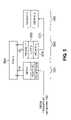
- FIG. 5illustrates an egress portion of the transport network environment according to a “Fast MAC” implementation of the present invention.
- FIG. 6illustrates the packet flow at various stages of the egress portion of the transport network environment of FIG. 5 .
- FIG. 1illustrates a conventional transport network 150 for communicating packets between an ingress local area network 110 and an egress local area network 160 .
- the transport network 150may be embodied, for example, as a SONET network, a Synchronous Digital Hierarchy (SDH) network or an Optical Transport Network (OTN). While the present invention is illustrated herein in the context of an exemplary SONET network 150 that transports Ethernet packets, the present invention may be employed in any optical transport network that maps asynchronous packets to a constant bit rate stream, for example, using the Generic Framing Procedure (GFP) mapping scheme or the High-Level Data Link Control (HDLC) protocol.
- GFPGeneric Framing Procedure
- HDLCHigh-Level Data Link Control
- a plurality of end stations 105 - 1 through 105 -N connected to local area network 110can transmit packets over a SONET link 150 to one or more end stations 170 - 1 through 170 -N connected to local area network 160 .
- the local area networks 110 , 160can be based, for example, on the Ethernet protocol, to interconnect the various end stations 105 - 1 through 105 -N within an enterprise.
- the packetsare encapsulated with the Generic Framing Procedure (GFP) mapping scheme which provides a fixed bandwidth overhead for each Ethernet packet.
- the packetsmay optionally be aggregated and prepared for transport on the transport network 150 by a GFP mapping function gateway 130 employing the Generic Framing Procedure (GFP) linear mapping scheme.
- GFPGeneric Framing Procedure
- the GFP mapping function 130When the packets are encapsulated, the GFP mapping function 130 assembles the asynchronous packets from the Ethernet-based local area network 110 into a constant bit rate stream, suitable for transport over the SONET network 150 , in a known manner. Similarly, a GFP mapping function 155 converts the constant bit rate stream received on the SONET network 150 into asynchronous packets suitable for the Ethernet-based local area network 160 .
- the GFP mapping function 155has an associated buffer (not shown in FIG. 1 ) for storing packets for the local area network 160 .
- the bufferaccommodates clocking differences between the higher rate transport network 150 and the local area network 110 , 160 .
- the egress buffer associated with the GFP mapping function 155will overflow under high bandwidth conditions.
- a frequency offset control mechanismis provided to adjust the bandwidth of the egress port so that the packets can be delivered without overflowing the buffer.
- the Ethernet standarddefines an inter-packet gap (IPG) as a recovery period for the remote receiver.
- An inter-packet gapis a specified number of bytes that are transmitted between each packet. Typically, an inter-packet gap consists of 12 bytes inserted between each packet.
- the present inventionrecognizes that the inter-packet gap can be adopted to now provide a frequency offset control mechanism that can adjust the bandwidth of the egress port in the event that the frequency of the ingress local area network 110 exceeds the frequency of the egress local area network 160 for Ethernet services over a GFP mapped transport network.
- the frequency offset control mechanism of the present inventionwill reduce the number of bytes included in the inter-packet gap when the frequency of the ingress local area network 110 is greater than the frequency of the egress local area network 160 , to prevent the egress buffer from overflowing. If the egress port has a slower clock than the ingress port, the additional bandwidth obtained by reducing the size of the inter-packet gap in accordance with the present invention will compensate for the frequency offset. If the egress port has a faster clock than the ingress port, then the inter-packet gap can be extended. It is noted that if there are no packets to send by the ingress local area network, the inter-packet gap will automatically be extended by conventional techniques to fill the idle time.
- a static implementation of the frequency offset control mechanism of the present inventioncan statically reduce the inter-packet gap at the egress port, for example, to 10 bytes. It is noted that in a static implementation of the present invention, the reduced inter-packet gap value is selected on the basis of the worst case frequency offset between the ingress and egress local area networks 110 , 160 . In a dynamic implementation of the present invention, the actual level of the egress buffer is monitored and the size of the inter-packet gap at the egress port is adjusted accordingly to maintain the level of the egress buffer within a desired range.
- FIG. 2illustrates a conventional format for a packet flow across the transport network 150 of FIG. 1 .
- a conventional packet flowincludes a series of packets 210 - 1 through 210 -N, each separated by a corresponding inter-packet gap 220 - 1 through 220 -N.
- a packet mapped over a GFP based transport networkincludes a start of packet indicator, a header (e.g., including address information), a payload (generally consisting of 64 to 1518 bytes) and an end of packet indicator.
- the inter-packet gapis typically 12 idle bytes in a conventional Ethernet system.
- FIG. 3illustrates a transport network environment according to a static implementation of the present invention.
- the local area network 110includes client equipment (CE) that generates packets to be transported over the transport network 150 .
- each packetis separated by an inter-packet gap that is generally 12 bytes.
- the inter-packet gapis inserted into the packet stream by the MAC layer (CE-MAC 1 ) of the client equipment.
- the physical layer (CE-PHY 1 )transmits the packet stream over a wire 315 from the local area network domain to a user-to-network interface (UNI) of the provider equipment (PE).
- the packet stream on the wire 315will have the format shown in FIG.
- the equipment shown in the dotted box 310all operates at the nominal frequency of the local area network 110 , which may be, for example, 10 Mbps, 100 Mbps or 1 Gbps (+/ ⁇ 100 ppm).
- the ingress provider equipment 340includes MAC and PHY layers.
- the physical layer in the ingress provider equipment (PE-PHY 1 )drops the inter-packet gap in the packet stream for transport over the network 150 , in a known manner.
- the ingress provider equipment 340provides the packet stream to a first-in-first-out buffer (FIFO 1 ).
- the buffer FIFO 1provides the packet stream to GFP mapping function 130 at a rate appropriate for the transport network 150 , such as the SONET rate of 155.52 MHz for a 1 Gbps Ethernet implementation.
- the GFP mapping function 130assembles the packets from the Ethernet-based local area network 110 into a constant bit rate stream, suitable for transport over the SONET network 150 , in a known manner.
- the packet streamis processed into a High Order or Low Order Virtual Concatenation (HO/LO VC) group and then placed in a optical carrier structure (OC-N) or a Synchronous Transport Mode (STM-N) structure and is then transported over the transport network 150 to the egress GFP mapping function 155 .
- HO/LO VCHigh Order or Low Order Virtual Concatenation
- OC-Noptical carrier structure
- STM-NSynchronous Transport Mode
- the GFP mapping function 155has an associated buffer (FIFO 2 ) 360 for storing packets for the local area network 160 .
- the buffer 360accommodates clocking differences between the higher rate transport network 150 and the local area network 160 .
- the egress buffer 360 associated with the GFP mapping function 155will overflow.
- the frequency of the local area network 160may each be, for example, 10 Mbps, 100 Mbps or 1 Gbps (+/ ⁇ 100 ppm).
- the expected worst-case frequency offset in the exemplary embodimentwill be 200 ppm.
- the present inventionprovides a frequency offset control mechanism to adjust the bandwidth of the egress port so that the packets can be delivered to the local area network 160 without overflowing the buffer 360 .
- the present inventionreduces the number of bytes in the inter-packet gap to adjust the bandwidth of the egress port in the event that the frequency of the ingress local area network 110 exceeds the frequency of the egress local area network 160 .
- the egress FIFO buffer 360provides the packet stream to the egress provider equipment 350 at a rate appropriate for the egress local area network 160 .
- the MAC layer (PE-MAC 2 ) of the egress provider equipment 350reintroduces the inter-packet gap between each packet in the packet stream.
- the MAC layer (PE-MAC 2 )is configured to insert an inter-packet gap having a size that is smaller than the inter-packet gap that was employed by the ingress local area network 110 .
- the inter-packet gap inserted into the packet stream by the MAC layer (CE-MAC 1 ) of the client equipment in the ingress local area network 110was 12 bytes
- the inter-packet gap inserted into the egress packet stream by the MAC layer (PE-MAC 2 )may be, for example, 10 bytes.
- the reduced inter-packet gap valueis selected on the basis of the worst case frequency offset between the ingress and egress local area networks 110 , 160 , and size of the inter-packet gap used by the ingress local area network.
- the physical layer (PE-PHY 2 ) 370 in the provider equipmenttransmits the packet stream over a wire 375 to the egress local area network domain.
- the packet stream on the wire 375will have the format shown in FIG. 2 , with a reduced inter-packet gap of 10 bytes in the exemplary embodiment.
- the equipment shown in the dotted box 330all operates at the nominal frequency of the local area network 160 , which may be, for example, 10 Mbps, 100 Mbps or 1 Gbps (+/ ⁇ 100 ppm).
- FIG. 4illustrates an egress portion of the transport network environment according to a dynamic implementation of the present invention. It is noted that the ingress portion of the transport network environment in a dynamic implementation may be embodied in the same form as described above in conjunction with FIG. 3 .
- the MAC layer (PE-MAC 2 ) of the egress provider equipmentis provided with an indicator, Fill_Lvl, indicating the instantaneous fill level of the FIFO buffer 460 .
- the MAC layer (PE-MAC 2 ) of the egress provider equipmentis provided with an upper threshold, HI, and a lower threshold, LO, that are employed to maintain the level of the egress buffer within a desired range.
- the dynamic implementation of the present inventionmonitors the actual level of the egress buffer 460 and dynamically adjusts the size of the inter-packet gap at the egress port to maintain the level of the egress buffer within the desired range.
- the nominal inter-packet gap inserted into the egress packet stream by the MAC layer (PE-MAC 2 )may be, for example, 10 bytes.
- the buffer fill level, Fill_Lvlis approaching the upper threshold, HI
- the inter-packet gapmay be reduced to a value lower than 10 bytes.
- the buffer fill level, Fill_Lvlis approaching the lower threshold, HI
- the inter-packet gapmay be increased to a value greater than 10 bytes.
- the MAC layer (PE-MAC 2 )may employ multiple threshold levels each having a corresponding degree of inter-packet gap variation.
- the dynamic implementation of the present inventiondoes not necessarily require knowledge of the size of the inter-packet gap employed by the ingress local area network.
- the dynamic implementation of the present inventionmay be preferred where multiple networks are traversed in the end-to-end path between the ingress local area network 110 and the egress local area network 160 .
- the static implementation of the present inventiondiscussed above in conjunction with FIG. 3 , results in a progressive reduction of the inter-packet gap size, with each traversed network.
- a dynamic implementation of the present inventioncan be configured to guarantee a minimum required inter-packet gap.
- FIG. 5illustrates an egress portion of the transport network environment according to a “Fast MAC” implementation of the present invention. It is noted that the ingress portion of the transport network environment in a dynamic implementation may be embodied in the same form as described above in conjunction with FIG. 3 .
- the Fast MAC embodiment of the present inventionoperates the MAC layer (PE-MAC 2 ) of the egress provider equipment at the clock rate of the transport network 150 .
- An elastic FIFO buffer 565is provided between the MAC (PE-MAC 2 ) and physical (PE-PHY 2 ) layers of the egress provider equipment to permit the MAC (PE-MAC 2 ) layer to operate at the clock rate of the transport network 150 and the physical (PE-PHY 2 ) layer to operate at the clock rate of the egress local area network 160 .
- the size of the elastic FIFO buffer 565is selected on the basis of the maximum packet (frame) length.
- the Fast MAC embodiment of the present inventiondoes not require knowledge of the frequency or inter-packet gap size employed by the ingress local area network 110 .
- FIG. 6illustrates the packet flow at various stages of the egress portion of the transport network environment of FIG. 5 .
- the CE-MAC 1 layersends a packet flow at the rate of the ingress local area network 110 , as shown by the packet stream 610 .
- the PE-MAC 2 layerwrites the packet stream into the elastic FIFO buffer 565 at the faster SONET rate and thereby extends the duration of the inter-packet gap, as shown by the packet stream 620 . Since the MAC 2 layer writes each packet more quickly, the inter-packet gaps are extended to fill the idle time.
- the PE-PHY 2 layerreads the packets out of the elastic FIFO buffer 565 at the slower rate of the egress local area network 160 and in order to keep up with the packet rate, it must delete some of the idle symbols form the inter-packet gap, as shown by the packet stream 630 .
- the size of the egress inter-packet gapis effectively reduced such that it is smaller than the ingress inter-packet gap during the worst case condition where the ingress frequency is greater than the egress frequency while running at full bandwidth.
Landscapes
- Engineering & Computer Science (AREA)
- Computer Networks & Wireless Communication (AREA)
- Signal Processing (AREA)
- Multimedia (AREA)
- Computer Hardware Design (AREA)
- Data Exchanges In Wide-Area Networks (AREA)
- Small-Scale Networks (AREA)
Abstract
Description
Claims (20)
Priority Applications (3)
| Application Number | Priority Date | Filing Date | Title |
|---|---|---|---|
| US10/643,005US7593327B2 (en) | 2003-08-18 | 2003-08-18 | Method and apparatus for frequency offset control of ethernet packets over a transport network |
| EP04252561AEP1509007A1 (en) | 2003-08-18 | 2004-04-30 | Method and apparatus for frequency offset control of ethernet packets over a transport network |
| JP2004237816AJP2005065300A (en) | 2003-08-18 | 2004-08-18 | Method and apparatus for frequency offset control of Ethernet packet on transport network |
Applications Claiming Priority (1)
| Application Number | Priority Date | Filing Date | Title |
|---|---|---|---|
| US10/643,005US7593327B2 (en) | 2003-08-18 | 2003-08-18 | Method and apparatus for frequency offset control of ethernet packets over a transport network |
Publications (2)
| Publication Number | Publication Date |
|---|---|
| US20050041695A1 US20050041695A1 (en) | 2005-02-24 |
| US7593327B2true US7593327B2 (en) | 2009-09-22 |
Family
ID=34063451
Family Applications (1)
| Application Number | Title | Priority Date | Filing Date |
|---|---|---|---|
| US10/643,005Active2026-04-23US7593327B2 (en) | 2003-08-18 | 2003-08-18 | Method and apparatus for frequency offset control of ethernet packets over a transport network |
Country Status (3)
| Country | Link |
|---|---|
| US (1) | US7593327B2 (en) |
| EP (1) | EP1509007A1 (en) |
| JP (1) | JP2005065300A (en) |
Cited By (6)
| Publication number | Priority date | Publication date | Assignee | Title |
|---|---|---|---|---|
| US20080273460A1 (en)* | 2007-05-03 | 2008-11-06 | Nortel Networks Limited | Methods and systems for communication between network elements |
| US20080291832A1 (en)* | 2002-10-31 | 2008-11-27 | Agere Systems Inc. | Method For Per-Port Flow Control Of Packets Aggregated From Multiple Logical Ports Over A Transport Link |
| US20090154492A1 (en)* | 2007-12-17 | 2009-06-18 | Wael William Diab | Method And System For A Distinct Physical Pattern On An Active Channel To Indicate A Data Rate Transition For Energy Efficient Ethernet |
| US20110170868A1 (en)* | 2005-06-29 | 2011-07-14 | Boyd Edward W | Method and Apparatus for Accommodating Differrent Clock Frequencies in an Ethernet Passive Optical Network |
| US20120140673A1 (en)* | 2009-09-02 | 2012-06-07 | Fujitsu Limited | Inter-frame gap controller, traffic transmitter, transmission apparatus and inter-frame gap control method |
| US9148382B2 (en) | 2012-02-15 | 2015-09-29 | Ciena Corporation | Adaptive Ethernet flow control systems and methods |
Families Citing this family (12)
| Publication number | Priority date | Publication date | Assignee | Title |
|---|---|---|---|---|
| CN1260926C (en)* | 2002-11-08 | 2006-06-21 | 华为技术有限公司 | Method for controlling flux in channel mapped by virtual container in metropolitan area transmission equipment |
| US20050058150A1 (en)* | 2003-09-16 | 2005-03-17 | Boles Glenn M. | Method and apparatus for enhancing packet communication |
| US7583599B1 (en)* | 2004-09-27 | 2009-09-01 | Intel Corporation | Transporting stream client signals via packet interface using GFP mapping |
| US7321600B2 (en)* | 2005-01-28 | 2008-01-22 | International Business Machines Corporation | System, method, and article of manufacture for initializing a communication link using GFP data frames |
| JP4752359B2 (en)* | 2005-07-07 | 2011-08-17 | 横河電機株式会社 | Frame rate generation circuit and frame rate generator |
| EP1764940A1 (en)* | 2005-09-20 | 2007-03-21 | Istituto Superiore Mario Boella | A media converter and a system for converting a packet-based data stream into a serial data stream und vice versa |
| US8379676B1 (en)* | 2006-06-01 | 2013-02-19 | World Wide Packets, Inc. | Injecting in-band control messages without impacting a data rate |
| US7760723B1 (en) | 2006-06-01 | 2010-07-20 | World Wide Packets, Inc. | Relaying a data stream from a data device to a network tunnel |
| US7653056B1 (en)* | 2006-06-02 | 2010-01-26 | World Wide Packets, Inc. | Virtual switching using a provisional identifier to conceal a user identifier |
| US8018938B1 (en) | 2006-06-02 | 2011-09-13 | World Wide Packets, Inc. | Translating between a switching format and a transport format |
| US7830883B1 (en) | 2006-12-19 | 2010-11-09 | World Wide Packets, Inc. | Modifying duplicate packets to have different transport formats |
| US9544237B1 (en)* | 2013-10-23 | 2017-01-10 | Marvell International Ltd. | Method and apparatus for inserting idle bytes in a data stream |
Citations (9)
| Publication number | Priority date | Publication date | Assignee | Title |
|---|---|---|---|---|
| US4849969A (en)* | 1988-05-19 | 1989-07-18 | Advanced Micro Devices, Inc. | Implementation of smoothing apparatus for an independently clocked network |
| US4849970A (en)* | 1988-05-19 | 1989-07-18 | Advanced Micro Devices, Inc. | Smoothing apparatus for an independently clocked network |
| US6226290B1 (en)* | 1998-04-28 | 2001-05-01 | Nortel Networks Limited | Method and apparatus for adjusting an interpacket gap using a network device in a data communications network |
| GB2362303A (en) | 2000-05-13 | 2001-11-14 | 3Com Corp | Repeater with controller for ensuring that the correct interpacket gap is written into an elasticity buffer |
| US20020034195A1 (en) | 2000-05-17 | 2002-03-21 | Jen-Kai Chen | Method for compensating for clock signal difference between a switch and a peripheral device, and associated apparatus |
| US20040202198A1 (en)* | 2003-03-24 | 2004-10-14 | Walker Timothy P. | 10 GbE LAN signal mapping to OTU2 signal |
| US7002941B1 (en)* | 1997-10-14 | 2006-02-21 | Alvarion Israel (2003) Ltd. | Method and apparatus for synchronizing fast ethernet data packets to radio frames in a wireless metropolitan area network |
| US7061866B2 (en)* | 2002-01-10 | 2006-06-13 | Intel Corporation | Metered packet flow for packet switched networks |
| US7089485B2 (en)* | 2000-02-03 | 2006-08-08 | Agere Systems Inc. | Simple link protocol providing low overhead coding for LAN serial and WDM solutions |
Family Cites Families (1)
| Publication number | Priority date | Publication date | Assignee | Title |
|---|---|---|---|---|
| US20040085904A1 (en)* | 2002-10-31 | 2004-05-06 | Bordogna Mark A. | Method for flow control of packets aggregated from multiple logical ports over a transport link |
- 2003
- 2003-08-18USUS10/643,005patent/US7593327B2/enactiveActive
- 2004
- 2004-04-30EPEP04252561Apatent/EP1509007A1/ennot_activeCeased
- 2004-08-18JPJP2004237816Apatent/JP2005065300A/enactivePending
Patent Citations (10)
| Publication number | Priority date | Publication date | Assignee | Title |
|---|---|---|---|---|
| US4849969A (en)* | 1988-05-19 | 1989-07-18 | Advanced Micro Devices, Inc. | Implementation of smoothing apparatus for an independently clocked network |
| US4849970A (en)* | 1988-05-19 | 1989-07-18 | Advanced Micro Devices, Inc. | Smoothing apparatus for an independently clocked network |
| US7002941B1 (en)* | 1997-10-14 | 2006-02-21 | Alvarion Israel (2003) Ltd. | Method and apparatus for synchronizing fast ethernet data packets to radio frames in a wireless metropolitan area network |
| US6226290B1 (en)* | 1998-04-28 | 2001-05-01 | Nortel Networks Limited | Method and apparatus for adjusting an interpacket gap using a network device in a data communications network |
| US7089485B2 (en)* | 2000-02-03 | 2006-08-08 | Agere Systems Inc. | Simple link protocol providing low overhead coding for LAN serial and WDM solutions |
| GB2362303A (en) | 2000-05-13 | 2001-11-14 | 3Com Corp | Repeater with controller for ensuring that the correct interpacket gap is written into an elasticity buffer |
| US6937624B1 (en)* | 2000-05-13 | 2005-08-30 | 3Com Corporation | System for manintaining inter-packet gaps in cascade transmission system for packet-based data |
| US20020034195A1 (en) | 2000-05-17 | 2002-03-21 | Jen-Kai Chen | Method for compensating for clock signal difference between a switch and a peripheral device, and associated apparatus |
| US7061866B2 (en)* | 2002-01-10 | 2006-06-13 | Intel Corporation | Metered packet flow for packet switched networks |
| US20040202198A1 (en)* | 2003-03-24 | 2004-10-14 | Walker Timothy P. | 10 GbE LAN signal mapping to OTU2 signal |
Non-Patent Citations (2)
| Title |
|---|
| "Generic Framing Procedure (GFP)," International Telecommunication Union, ITU-T G.7041/Y.1303-Prepublished Verion, Telecommunication Standardization Sector of ITU, Series G: Transmission Systems and Media, Digital Systems and Networks, Series Y: Global Information Infrastructure and Internet Protocol Aspects, Internet Protocol Aspects-Transport (Dec. 2001). |
| Scholten et al., "Rate Adaptation in Transparent GFP Mapping," Contribution to T1 Standards Project, XX, XX, pp. 1-7 (Mar. 26, 2001). |
Cited By (13)
| Publication number | Priority date | Publication date | Assignee | Title |
|---|---|---|---|---|
| US20080291832A1 (en)* | 2002-10-31 | 2008-11-27 | Agere Systems Inc. | Method For Per-Port Flow Control Of Packets Aggregated From Multiple Logical Ports Over A Transport Link |
| US7813285B2 (en)* | 2002-10-31 | 2010-10-12 | Agere Systems Inc. | Method for per-port flow control of packets aggregated from multiple logical ports over a transport link |
| US20110170868A1 (en)* | 2005-06-29 | 2011-07-14 | Boyd Edward W | Method and Apparatus for Accommodating Differrent Clock Frequencies in an Ethernet Passive Optical Network |
| US8588257B2 (en)* | 2005-06-29 | 2013-11-19 | Broadcom Corporation | Method and apparatus for accommodating differrent clock frequencies in an ethernet passive optical network |
| US8467417B2 (en)* | 2007-05-03 | 2013-06-18 | Rockstar Consortium Us Lp | Method and system for synchronization between network elements |
| US20080273460A1 (en)* | 2007-05-03 | 2008-11-06 | Nortel Networks Limited | Methods and systems for communication between network elements |
| US20130272321A1 (en)* | 2007-05-03 | 2013-10-17 | Rockstar Consortium Us Lp | Method and system for synchronization between network elements |
| US8811432B2 (en)* | 2007-05-03 | 2014-08-19 | Rockstar Consortium Us Lp | Method and system for synchronization between network elements |
| US20090154492A1 (en)* | 2007-12-17 | 2009-06-18 | Wael William Diab | Method And System For A Distinct Physical Pattern On An Active Channel To Indicate A Data Rate Transition For Energy Efficient Ethernet |
| US9455912B2 (en)* | 2007-12-17 | 2016-09-27 | Broadcom Corporation | Method and system for a distinct physical pattern on an active channel to indicate a data rate transition for energy efficient ethernet |
| US20120140673A1 (en)* | 2009-09-02 | 2012-06-07 | Fujitsu Limited | Inter-frame gap controller, traffic transmitter, transmission apparatus and inter-frame gap control method |
| US9054824B2 (en)* | 2009-09-02 | 2015-06-09 | Fujitsu Limited | Inter-frame gap controller, traffic transmitter, transmission apparatus and inter-frame gap control method |
| US9148382B2 (en) | 2012-02-15 | 2015-09-29 | Ciena Corporation | Adaptive Ethernet flow control systems and methods |
Also Published As
| Publication number | Publication date |
|---|---|
| EP1509007A1 (en) | 2005-02-23 |
| US20050041695A1 (en) | 2005-02-24 |
| JP2005065300A (en) | 2005-03-10 |
Similar Documents
| Publication | Publication Date | Title |
|---|---|---|
| US7813285B2 (en) | Method for per-port flow control of packets aggregated from multiple logical ports over a transport link | |
| US7593327B2 (en) | Method and apparatus for frequency offset control of ethernet packets over a transport network | |
| US7876785B2 (en) | Transport of aggregated client packets | |
| CN100531130C (en) | Method and system for controlling flow based on bandwidth adjusting mechanism | |
| WO2017202158A1 (en) | Data forwarding method and device | |
| US7593431B1 (en) | Method and system for monitoring a MAC extra IPG count and adjusting the PHY transmit IPG | |
| US6731654B1 (en) | Communication system overhead channel | |
| US6993046B1 (en) | Mapping of block-encoded data formats onto a bit/byte synchronous transport medium | |
| US7751335B2 (en) | Failure handling system | |
| US7313144B2 (en) | Frame transmission device | |
| EP1339183B1 (en) | Method and device for transporting ethernet frames over a transport SDH/SONET network | |
| US7305013B2 (en) | Handling traffic in a synchronous communication network | |
| US8792461B2 (en) | Method, apparatus and system for scheduling service on microwave link | |
| US7286469B2 (en) | Network synchronization device, system and method | |
| US20070086479A1 (en) | Techniques to buffer traffic in a communications system | |
| JP2002223202A (en) | Data transmission method and transmission device using the same | |
| US7590130B2 (en) | Communications system with first and second scan tables | |
| EP1339198B1 (en) | Enhanced transport of ethernet traffic over a transport SDH/SONET network | |
| US20060133383A1 (en) | Communications system with scan table identification | |
| US8515283B2 (en) | Transparent fiber channel link management for protocol transport | |
| US7289507B2 (en) | Method and network element for a safety transport of ethernet frames over a transport SDH/SONET network | |
| US7088738B1 (en) | Dynamic fragmentation of information | |
| KR20040002040A (en) | packet transfer method using the Virtual Concatenation in EtherNet-based Digital Subscriber Line | |
| Nguyên et al. | Circuit emulation service technologies and modified packet bursting in metropolitan optical networks | |
| KR100943079B1 (en) | Ethernet interface device |
Legal Events
| Date | Code | Title | Description |
|---|---|---|---|
| AS | Assignment | Owner name:AGERE SYSTEMS INC., PENNSYLVANIA Free format text:ASSIGNMENT OF ASSIGNORS INTEREST;ASSIGNORS:BORDOGNA, MARK ALDO;HEALEY, ADAM B.;STROPPARO, PETER A.;REEL/FRAME:015119/0237;SIGNING DATES FROM 20040105 TO 20040308 | |
| STCF | Information on status: patent grant | Free format text:PATENTED CASE | |
| CC | Certificate of correction | ||
| FPAY | Fee payment | Year of fee payment:4 | |
| AS | Assignment | Owner name:DEUTSCHE BANK AG NEW YORK BRANCH, AS COLLATERAL AG Free format text:PATENT SECURITY AGREEMENT;ASSIGNORS:LSI CORPORATION;AGERE SYSTEMS LLC;REEL/FRAME:032856/0031 Effective date:20140506 | |
| AS | Assignment | Owner name:AVAGO TECHNOLOGIES GENERAL IP (SINGAPORE) PTE. LTD Free format text:ASSIGNMENT OF ASSIGNORS INTEREST;ASSIGNOR:AGERE SYSTEMS LLC;REEL/FRAME:035059/0001 Effective date:20140804 Owner name:AGERE SYSTEMS LLC, PENNSYLVANIA Free format text:MERGER;ASSIGNOR:AGERE SYSTEMS INC.;REEL/FRAME:035058/0895 Effective date:20120724 | |
| AS | Assignment | Owner name:AGERE SYSTEMS LLC, PENNSYLVANIA Free format text:TERMINATION AND RELEASE OF SECURITY INTEREST IN PATENT RIGHTS (RELEASES RF 032856-0031);ASSIGNOR:DEUTSCHE BANK AG NEW YORK BRANCH, AS COLLATERAL AGENT;REEL/FRAME:037684/0039 Effective date:20160201 Owner name:LSI CORPORATION, CALIFORNIA Free format text:TERMINATION AND RELEASE OF SECURITY INTEREST IN PATENT RIGHTS (RELEASES RF 032856-0031);ASSIGNOR:DEUTSCHE BANK AG NEW YORK BRANCH, AS COLLATERAL AGENT;REEL/FRAME:037684/0039 Effective date:20160201 | |
| AS | Assignment | Owner name:BANK OF AMERICA, N.A., AS COLLATERAL AGENT, NORTH CAROLINA Free format text:PATENT SECURITY AGREEMENT;ASSIGNOR:AVAGO TECHNOLOGIES GENERAL IP (SINGAPORE) PTE. LTD.;REEL/FRAME:037808/0001 Effective date:20160201 Owner name:BANK OF AMERICA, N.A., AS COLLATERAL AGENT, NORTH Free format text:PATENT SECURITY AGREEMENT;ASSIGNOR:AVAGO TECHNOLOGIES GENERAL IP (SINGAPORE) PTE. LTD.;REEL/FRAME:037808/0001 Effective date:20160201 | |
| AS | Assignment | Owner name:AVAGO TECHNOLOGIES GENERAL IP (SINGAPORE) PTE. LTD., SINGAPORE Free format text:TERMINATION AND RELEASE OF SECURITY INTEREST IN PATENTS;ASSIGNOR:BANK OF AMERICA, N.A., AS COLLATERAL AGENT;REEL/FRAME:041710/0001 Effective date:20170119 Owner name:AVAGO TECHNOLOGIES GENERAL IP (SINGAPORE) PTE. LTD Free format text:TERMINATION AND RELEASE OF SECURITY INTEREST IN PATENTS;ASSIGNOR:BANK OF AMERICA, N.A., AS COLLATERAL AGENT;REEL/FRAME:041710/0001 Effective date:20170119 | |
| FPAY | Fee payment | Year of fee payment:8 | |
| AS | Assignment | Owner name:AVAGO TECHNOLOGIES INTERNATIONAL SALES PTE. LIMITE Free format text:MERGER;ASSIGNOR:AVAGO TECHNOLOGIES GENERAL IP (SINGAPORE) PTE. LTD.;REEL/FRAME:047195/0827 Effective date:20180509 | |
| AS | Assignment | Owner name:AVAGO TECHNOLOGIES INTERNATIONAL SALES PTE. LIMITE Free format text:CORRECTIVE ASSIGNMENT TO CORRECT THE EFFECTIVE DATE OF MERGER PREVIOUSLY RECORDED AT REEL: 047195 FRAME: 0827. ASSIGNOR(S) HEREBY CONFIRMS THE MERGER;ASSIGNOR:AVAGO TECHNOLOGIES GENERAL IP (SINGAPORE) PTE. LTD.;REEL/FRAME:047924/0571 Effective date:20180905 | |
| MAFP | Maintenance fee payment | Free format text:PAYMENT OF MAINTENANCE FEE, 12TH YEAR, LARGE ENTITY (ORIGINAL EVENT CODE: M1553); ENTITY STATUS OF PATENT OWNER: LARGE ENTITY Year of fee payment:12 |