US7593041B2 - System and method for a software steerable web camera with multiple image subset capture - Google Patents
System and method for a software steerable web camera with multiple image subset captureDownload PDFInfo
- Publication number
- US7593041B2 US7593041B2US11/428,525US42852506AUS7593041B2US 7593041 B2US7593041 B2US 7593041B2US 42852506 AUS42852506 AUS 42852506AUS 7593041 B2US7593041 B2US 7593041B2
- Authority
- US
- United States
- Prior art keywords
- image data
- subsets
- scene
- digitized
- scene image
- Prior art date
- Legal status (The legal status is an assumption and is not a legal conclusion. Google has not performed a legal analysis and makes no representation as to the accuracy of the status listed.)
- Expired - Lifetime, expires
Links
Images


Classifications
- H—ELECTRICITY
- H04—ELECTRIC COMMUNICATION TECHNIQUE
- H04N—PICTORIAL COMMUNICATION, e.g. TELEVISION
- H04N23/00—Cameras or camera modules comprising electronic image sensors; Control thereof
- H04N23/60—Control of cameras or camera modules
- H04N23/698—Control of cameras or camera modules for achieving an enlarged field of view, e.g. panoramic image capture
- G—PHYSICS
- G06—COMPUTING OR CALCULATING; COUNTING
- G06T—IMAGE DATA PROCESSING OR GENERATION, IN GENERAL
- G06T1/00—General purpose image data processing
- G06T1/0007—Image acquisition
- H—ELECTRICITY
- H04—ELECTRIC COMMUNICATION TECHNIQUE
- H04N—PICTORIAL COMMUNICATION, e.g. TELEVISION
- H04N23/00—Cameras or camera modules comprising electronic image sensors; Control thereof
- H04N23/58—Means for changing the camera field of view without moving the camera body, e.g. nutating or panning of optics or image sensors
Definitions
- This disclosurerelates generally to digital imaging, digital video or web cameras, and more particularly but not exclusively, to systems and methods for capturing camera images by use of software control.
- webcamscan be used for teleconferencing, surveillance, and other purposes.
- One of the problems with conventional webcamsis that they have a very restricted field of vision. This restricted vision field is due to the limitations in the mechanism used to control the webcam and in the optics and other components in the webcam.
- the usermight manually control the webcam to pan and/or tilt in various directions (e.g., side-to-side or up-and-down) and/or to zoom in or away from an image to be captured.
- this manual techniqueis inconvenient, as it requires the user to stop whatever he/she is doing, to readjust the webcam, and to then resume his/her previous activity.
- FIG. 1is a block diagram showing a webcam coupled to a set top box according to an embodiment of the invention.
- FIG. 2is a block diagram of an embodiment of the webcam of FIG. 1 .
- FIG. 3is a block diagram of an embodiment of the set top box of FIG. 1 .
- FIG. 4is a block diagram of one example of a memory device of the set top box.
- FIG. 5Ais an illustrative example block diagram showing a function of the webcam of FIG. 1 in response to particular pan and/or tilt commands.
- FIG. 5Bis an illustrative example block diagram of selected subsets in a digitized scene image data in response to particular pan and/or tilt commands.
- FIG. 6Ais an illustrative example block diagram of a selected subset image data with distortions.
- FIG. 6Bis an illustrative example block diagram of a selected subset image data that has been distortion compensated.
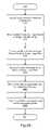
- FIG. 7is a flowchart of a method according to an embodiment of the invention.
- FIG. 8Ais an illustrative example block diagram showing a function of the webcam of FIG. 1 in response to particular pan and zoom commands.
- FIG. 8Bis an illustrative example block diagram of a selected subset in the digitized scene image data in response to a particular pan command.
- FIG. 8Cis an illustrative example block diagram of the selected subset in FIG. 8B in response to a particular zoom command.
- FIG. 9is an illustrative example block diagram of the selected subset in FIG. 9 in response to another particular zoom command.
- FIG. 10is a flowchart of a method according to another embodiment of the invention.
- FIG. 11is another diagram shown to further assist in describing an operation of an embodiment of the invention.
- FIG. 12is a diagram illustrating an operation of an embodiment of the invention.
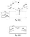
- FIG. 13Ais an illustrative example block diagram showing a function of the camera of FIG. 12 in response to particular pan, tilt, and/or zoom commands.
- FIG. 13Bis an illustrative example block diagram of selected subsets in a digitized scene image data in response to particular pan, tilt, and/or zoom commands.
- FIG. 14is a diagram illustrating an operation of another embodiment of the invention.
- FIG. 15is an illustrative example block diagram of selected particular subsets a digitized scene image data related to FIG. 14 .
- FIG. 16is a diagram illustrating another operation of an embodiment of the invention where selected image data subsets overlap.
- FIG. 17is an illustrative example block diagram of selected subsets in a digitized scene image data where at least some of the selected subsets overlap.
- FIG. 18Ais a diagram illustrating another operation of an embodiment of the invention.
- FIG. 18Bis an illustrative example block diagram of selected particular subsets a digitized scene image data related to FIG. 18A .
- FIG. 19Ais a diagram illustrating an operation of an embodiment of the invention where image data subsets are transmitted from a camera to a destination device.
- FIG. 19Bis a diagram illustrating an operation of an embodiment of the invention where image data subsets are transmitted from a customer premise equipment to a destination device.
- FIG. 20is a flowchart of a method according to another embodiment of the invention.
- an embodiment of the inventionprovides a system and method that capture camera images by use of software control.
- the cameramay be web camera or other types of camera that can support a wide angle lens.
- the wide angle lensis used to capture a scene or image in the wide field of vision.
- the captured scene or image datais then stored in an image collection array and then digitized and stored in memory.
- the image collection arrayis a relatively larger sized array to permit the array to store image data from the wide vision field. Processing is performed for user commands to effectively pan or tilt the webcam in particular directions and/or to zoom the webcam toward or away from an object to be captured as an image.
- a particular subset of the digitized datais selected and processed so that selected subset data provides a simulated panning, tilting, and/or zooming of the image of the captured object.
- a compression/correction enginecan then compensate the selected subset data for distortion and compress the selected subset data for transmission.
- a plurality of subsets in the digitized dataare selected and processed prior to transmitting the data subsets to a destination device.
- Particular subsetsmay be overlapping or non-overlapping in the digitized data.
- a motion detectormay, for example, be used to determine the location of at least one of the data subsets. This embodiment may permit a single camera to simulate multiple virtual cameras, since images from multiple focus areas can be serially captured and integrated into a single, integrated output image.
- the inventionadvantageously permits a camera, such as a webcam, to have a wide vision field.
- the inventionmay also advantageously provide a wide vision field for cameras that have short depth fields.
- the inventionalso advantageously avoids the use of stepper motors to obtain particular images based on pan and zoom commands from the user.
- FIG. 1is a block diagram showing a webcam 100 coupled to a set top box (“STB”) 140 according to an embodiment of the invention.
- the webcam 100can capture an image of an object 130 that is in the webcam field of vision.
- Webcam 100is coupled to STB 140 via, for example, a cable 110 .
- Webcam 100may also be coupled to STB 140 by use of other suitable connections or methods, such as IR beams, radio signals, suitable wireless transmission techniques, and the like.
- STB 140is coupled to a cable network 160 and receives TV broadcasts, as well as other data, from the cable network 160 .
- STB 140is also coupled to the Internet 150 or other networks for sending and receiving data. Data received from the Internet 150 or cable network 160 may be displayed on a display 120 .
- STB 140may also transmit images that are captured by the webcam 100 to other computers via the Internet 150 .
- STBmay also transmit the captured webcam images to a printer 165 and/or to other devices 170 such as a computer in
- embodiments of the inventionmay also be implemented in other types of suitable cameras that can support a wide angle lens.
- an embodiment of the inventionmay be implemented in, for example, security cameras, ATM cash machine cameras, spy cameras, portable cameras, or pin-hole type cameras.
- the inventionis not limited to the use of STB 140 .
- Other processing devicemay be used according to embodiments of the invention to perform image distortion compensation, image compression, and/or other functions that will be described below.
- FIG. 2is a block diagram of an embodiment of the webcam 100 of FIG. 1 .
- Webcam 100comprises a lens 210 ; a shutter 220 ; a filter 230 ; an image collection array 240 ; a sample stage 245 ; and an analog to digital converter (“ADC”) 250 .
- the lens 210may be a wide angle lens, such as a fish-eye lens, that has angular field of, for example, at least about 140 degrees, as indicated by lines 200 . Using a wide-angle lens allows webcam 100 to capture a larger image area than a conventional webcam.
- Shutter 220opens and closes at a pre-specified rate, allowing light into the interior of webcam 100 and onto a filter 230 .
- Filter 230allows for image collection array 240 to capture different colors of an image and may include a static filter, such as a Bayer filter, or may include a spinning disk filter. In another embodiment, the filter may be replaced with a beam splitter or other color differentiation device. In another embodiment, webcam 100 does not include a filter or other color differentiation device.
- the image collection array 240can include charge coupled device (“CCD”) sensors or complementary metal oxide semiconductor (“CMOS”) sensors, which are generally much less expensive than CCD sensors but may be more susceptible to noise. Other types of sensors may be used in the image collection array 240 .
- the size of the image collection array 240is relatively larger in size such as, for example, 1024 by 768, 1200 by 768, or 2000 by 1000 sensors. The large sized array permits the array 240 to capture images in the wide vision field 200 that is viewed by the webcam 200 .
- a sample stage 245reads the image data from the image collection array 240 when shutter 220 is closed, and an analog-to-digital converter (ADC) 250 converts the image data from an analog to digital form, and feeds the digitized image data to STB 140 via cable 110 for processing and/or transmission.
- ADCanalog-to-digital converter
- the image datamay be processed entirely by components of the webcam 100 and transmitted from webcam 100 to other devices such as the printer 165 or computer 170 .
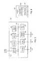
- FIG. 3is a block diagram of an embodiment of the set top box (STB) 140 .
- STB 140includes a network interface 300 ; a processor 310 ; a memory device 320 ; a frame buffer 330 ; a converter 340 ; a modem 350 ; a webcam interface 360 , and an input device 365 , all interconnected for communication by system bus 370 .
- Network interface 300connects the STB 140 to the cable network 160 ( FIG. 1 ) to receive videocasts from the cable network 160 .
- the modem 350 or converter 340may provide some or all of the functionality of the network interface 300 .
- Frame buffer 330holds preprocessed data received from webcam 100 via webcam interface 360 .
- the frame buffer 330is omitted since the data from webcam 100 may be loaded into memory 320 instead of loading the data into the frame buffer 330 .
- Modem 350may be a conventional modem for communicating with the Internet 150 via a publicly switched telephone network.
- the modem 350can transmit and receive digital information, such as television scheduling information, the webcam 100 output images, or other information to Internet 150 .
- modem 350may be a cable modem or a wireless modem for sending and receiving data from the Internet 150 or other network.
- Webcam interface 360is coupled to webcam 100 and receives image output from the webcam 100 .
- Webcam interface 360may include, for example, a universal serial bus (USB) port, a parallel port, an infrared (IR) receiver, or other suitable device for receiving data.
- Input device 365may include, for example, a keyboard, mouse, joystick, or other device or combination of devices that a user (local or remote) uses to control the pan, tilt, and/or zoom webcam 100 by use of software control according to embodiments of the invention.
- input device 365may include a wireless device, such an infrared IR remote control device that is separate from the STB 140 .
- the STB 140also may include an IR receiver coupled to the system bus 370 to receive IR signals from the remote control input device.
- the components shown in FIG. 3may be configured in other ways and in addition, the components may also be integrated. Thus, the configuration of the STB 140 in FIG. 3 is not intended to be limiting.
- FIG. 4is a block diagram of an example of a memory device 320 of the set top box 140 .
- Memory device 320may be, for example, a hard drive, a disk drive, random access memory (“RAM”), read only memory (“ROM”), flash memory, or any other suitable memory device, or any combination thereof.
- Memory device 320stores, for example, a compression/correction engine 400 that performs compression and distortion compensation on the image data received from webcam 100 .
- Memory device 320also stores, for example, a webcam engine 410 that accepts and process user commands relating to the pan, tilt, and/or zoom functions of the webcam 100 , as described below.
- compression/correction engine 400 and/or the webcam engine 410may be stored in other storage areas that are accessible by the processor 310 . Furthermore, the compression/correction engine 400 and/or the webcam engine 410 and/or a suitable processor for executing software may be stored in the webcam 100 . It is noted that either one of the compression/correction engine 400 or webcam engine 410 may be implemented, for example, as a program, module, instruction, or the like.
- Compression/correction engine 400uses, for example, any known suitable skew correction algorithm that compresses a subset of the image output from webcam 100 and that compensates the subset image output for distortion.
- the distortion compensation of the subset image outputmay be performed before the compression of the subset image output.
- the distortionis automatically corrected in the subset image output when performing the compression of the subset image output, and this leads to a saving in processor resource.
- Webcam engine 410accepts input from a user including instructions to pan or tilt the webcam 100 in particular directions and/or to zoom the webcam 100 toward or away from an object to be captured as an image.
- FIGS. 5A and 5Billustrate examples of operations of an embodiment of the invention.
- FIG. 5Ais a block diagram illustrating a top view of webcam 100 .
- the vision field 200 of the wide angle lens 210 of webcam 100captures a wide scene area including the three objects 480 , 482 , and 484 .
- a conventional webcammay only be able to capture the scene area in the limited vision field 481 .
- a conventional webcammay need manual adjustment or movement by stepper motors to capture the objects 480 or 484 that are outside of the limited vision field 481 .
- the entire scene captured in the vision field 200is stored as an image in the image collection array 240 ( FIG. 2 ) and processed by sample stage 245 and ADC stage 250 , and the image data of the entire scene is stored as digitized scene image data 485 in frame buffer 330 (or memory 320 ).
- each position in the scene area that is covered by vision field 200corresponds to a position in the image collection array 240 ( FIG. 2 ).
- the values in the positions in the image collection array 240are then digitized as values of the digitized scene image data 485 .
- the webcam engine 410( FIG. 4 ) allows a user to select a subset area in the vision field 200 for display or transmission, so as to simulate a panning/tilting feature of conventional webcams that use stepper motors. For example, assume that the digitized image data 485 was captured in response to a user directly or remotely sending a command 486 via input device 365 to pan the webcam 100 to the left in order to permit the capture of an image of the object 480 . The webcam engine 410 receives the pan left command 486 and accordingly samples an area 487 that contains an image of the object 480 in the digitized scene image data 485 .
- the webcam engine 410selects an area (subset) 489 that contains an image of the object 484 in the digitized scene image data 485 .
- the webcam engine 410selects a subset 496 that contains an image of the bottom portion 498 of object 484 in the digitized scene image data 485 .
- Webcam engine 410then passes a selected area (e.g., selected area 487 , 489 , 496 ) to the compression/correction engine 400 ( FIG. 4 ).
- the compression/correction engine 400then performs compression operation and distortion compensation.
- the selected area 487shows distortions 490 in the image of 480 as a result of using the wide angle lens 210 .
- the compression/correction engine 400can perform distortion compensation to reverse the distortion caused by the wide angle lens 210 on the captured image of object 480 . Typically, this compensation is performed by changing the curved surface of an image into a straight surface.
- FIG. 6Bshows an image of the object 480 without distortions after applying distortion compensation on the selected area 487 .
- the image of the object 480is shown as a normal rectilinear image.
- the selected area 487can then be compressed by the compression/correction engine 400 .
- the compression and distortion compensation for selected area 487can be performed concurrently.
- the distortion compensation for selected area 487can be performed before compression of the selected area 487 .
- the webcam engine 410then passes the compressed distortion-compensated selected image data 487 to an output device, such as display 120 ( FIG. 1 ) for viewing, or to the printer 165 or other devices such as computer 170 .
- webcam engine 410may transmit the data 487 to another device coupled to the Internet 150 .
- FIG. 7is a flowchart of a method 600 to perform a panning, tilting or zooming function according to an embodiment of the invention.
- a userfirst sends ( 605 ) a pan/tilt command indicating a direction of an object to be captured in an image by a webcam.
- a scene in the field of vision of a lens of the webcamis then captured ( 605 ).
- the captured sceneis in the vision field 200 ( FIG. 2 ) of a wide angle lens 210 of the webcam 100 .
- the captured scene in the vision fieldis then stored ( 615 ) as scene image data in an image collection array.
- the image collection arraymay, for example, include charge coupled devices or complementary metal oxide semiconductor sensors.
- the scene image data in the image collection arrayis then processed and stored ( 620 ) as a digitized scene image data.
- the digitized scene datamay be stored in, for example, the frame buffer 330 in the set top box 140 or other processing device.
- a subset of the digitized scene image datais selected ( 625 ).
- the webcam engine 410processes the pan/tilt/zoom command(s) and selects the subset of the digitized scene image data based on the pan/tilt/zoom command(s).
- Distortion compensation and compressionis then performed ( 630 ) on the subset of the digitized scene image data.
- the compression/correction engine 400performs ( 630 ) the distortion compensation and compression of the subset of the digitized scene image data.
- the distortion-compensated and compressed subsetis then transmitted ( 635 ) to a selected destination such as display 120 , to another device via Internet 150 or cable network 160 , to printer 165 , and/or to computer 170 .
- FIGS. 8A and 8Billustrate an example of another operation of an embodiment of the invention.
- the usersends a command 700 in order to capture an image of the object 710 and another command 705 to zoom the image of the object 710 .
- a conventional webcamwill require a physical pan movement to the left to capture the image of the object 705 and to capture a zoomed image of the object 705 .
- the digitized scene image data 485 of the scene in the vision field 200was captured in the manner described above.
- the webcam engine 410receives the pan left command 700 and accordingly selects an area 715 that contains an image of the object 710 in the digitized scene image data 485 .
- the compression/correction engine 400can perform distortion compensation to reverse the distortion caused by the wide angle lens 210 on the captured image of object 710 . Typically, this compensation is performed by changing the curved surface of an image into a straight surface.
- the webcam engine 410in response to the zoom command 705 , can enlarge an image of the selected area 715 in, for example, the frame buffer 330 .
- the compression/correction engine 400can then compress the image of selected area 715 and transmit the compressed image to a destination such as the display 120 or other suitable devices.
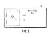
- FIGS. 8A and 9describe another function according to an embodiment of the invention.
- the usersends a command 700 in order to capture an image of the object 710 and another command 740 to zoom away from the object 710 .
- the webcam engine 410receives the pan left command 700 and accordingly selects an area 750 that contains an image of the object 710 in the digitized scene image data 485 .
- the selected area 750will be larger in size and cover a greater selected area portion in the digitized scene image area 485 than the selected area 715 in FIG. 8B .
- FIG. 10is a flowchart of a method 800 to perform a zooming function according to an embodiment of the invention.
- a userfirst sends ( 805 ) a zoom command indicating whether to zoom in or away from an object to be captured in an image by a webcam.
- a scene in the field of vision of the lens of the webcamis then captured ( 810 ).
- the captured scene in the vision fieldis then stored ( 815 ) as scene image data in an image collection array.
- the scene image data in the image collection arrayis then processed and stored ( 820 ) as a digitized scene image data.
- Based on the zoom commanda subset of the digitized scene image data is selected ( 825 ).
- Processing of the subset of the digitized scene image datais then performed ( 827 ) based on the zoom command. For example, if the zoom command is for zooming the image of the captured object, then the subset of the digitized scene image data is enlarged. As another example, if the zoom command is for zooming away from the captured object, then the selected subset will cover a greater area in the digitized scene image data.
- Distortion compensation and compressionare then performed ( 830 ) on the subset of the digitized scene image data.
- the distortion-compensated and compressed subsetis then transmitted ( 835 ) to a selected destination such as display 120 , to another device via Internet 150 or cable network 160 , to printer 165 , and/or to computer 170 .
- FIG. 11is another diagram shown to further assist in describing an operation of an embodiment of the invention.
- a scene 900falls within the vision field 905 of a wide angle lens 910 of a camera 915 .
- the captured sceneis digitized and processed into a digitized scene data 920 .
- a subset 925 of the digitized scene data 920is selected based on a pan, tilt, and/or zoom command(s) that can be transmitted from an input device by the user.
- the selected subset 925may be skew corrected (e.g., distortion compensated) into scene data 930 that can be transmitted to a destination.
- the scene data 930is also typically compressed in order to optimize the data transmission across a network.
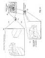
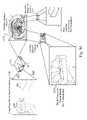
- FIG. 12is diagram illustrating an operation of another embodiment of the invention.
- a scene 1000falls within the vision field 1005 of a wide angle lens 1010 of a camera 1015 .
- the captured sceneis digitized and processed into a digitized scene data 1020 .
- a first subset 1025 of the digitized scene data 1020is selected based on a pan, tilt, and/or zoom command(s) that can be transmitted from an input device by the user.
- the first subset 1025corresponds to a scene area with object 1042 that is focused upon by the camera 1015 .
- the selected subset 1025may be skew corrected (e.g., distortion compensated) into scene data 1030 that can be transmitted to a destination.
- the scene data 1030is also typically compressed in order to optimize the data transmission across a network.
- a mechanically-based pan/tilt/zoom camerais limited to its focused field of vision when capturing an image. As a result, any movement that occurs outside the focus of the camera is not visible to the camera.
- the specific embodiment shown in FIG. 12overcomes this limitation of mechanically-based cameras.
- a motion detector 1040can cause the focus of the camera 1015 to change by transmitting commands 1045 to cause the focus of the software-steerable camera 1015 to change. As a result, the software-steerable camera 1015 can change its focus to an area of the field of vision 1005 where movement or activity was detected by the motion detector 1040 .
- the motion detector 1015detects activity outside the scene area of object 1042 and near the scene area of object 1050 .
- the motion detector 1040issues a command 1045 so that the software-steerable camera 1015 selects a subset 1055 which corresponds to an area in the scene 1000 with the detected activity.
- the elements for permitting the software-based steering functions previously described abovee.g., webcam engine 410 , processor for executing webcam engine 410 , and so on
- the elements for permitting the software-based steering functions previously described aboveare included in the camera 1015 .
- the selected subset 1055may be skew corrected (e.g., distortion compensated) into scene data 1060 that can be transmitted to a destination.
- the scene data 1060is also typically compressed in order to optimize the data transmission across a network.
- subsets 1025 and 1055may be selected in FIG. 12 .
- FIGS. 13A and 13Billustrate an example of another operation of an embodiment of the invention.
- the usersends a command 1100 (by use of, for example, input device 365 ) in order to capture an image of the object 1042 .
- the user of input device 365can be local or remote to the camera location in any of the various embodiments described above. Thus, remote access is optionally allowed.
- a conventional webcamwill require a physical pan movement to the left to capture the image of the object 1042 .
- the webcam engine 410receives the pan left command 1100 and accordingly selects an area (subset) 1025 that contains an image of the object 1042 in the digitized scene image data 1020 .
- the compression/correction engine 400( FIG. 4 ) can perform distortion compensation to reverse the distortion caused by the wide angle lens 1010 on the captured image of object 1042 .
- the motion detector 1040detects the activity and responsively transmits a command (e.g., pan right command) 1125 that is processed by webcam engine 410 .
- a commande.g., pan right command
- webcam engine 410In response to the command 1125 , webcam engine 410 accordingly selects an area (subset) 1055 that contains an image of the object 1050 in the digitized scene image data 1020 .
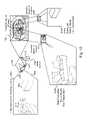
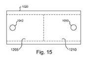
- FIG. 14shows another specific embodiment where the camera 1015 captures at least two selected areas in the scene 1000 .
- the captured scene 1000is digitized and processed into a digitized scene data 1020 .
- a first subset 1205 of the digitized scene data 1020is selected by webcam engine 410 ( FIG. 4 ) based on, for example, a pan, tilt, and/or zoom command(s) that can be transmitted from an input device by the user, while a second subset 1210 in the digitized scene data 1020 is, for example, automatically selected by the webcam engine 410 .
- the first subset 1205corresponds to a scene area with object 1042 that is focused upon by the camera 1015
- the second subset 1210may correspond to a scene area outside the scene area associated with first subset 1205
- the selected subsets 1205 and 1210may then be skew corrected (e.g., distortion compensated) into scene data 1215 and 1220 , respectively.
- the scene data 1215 and 1220may be can be transmitted to a destination.
- webcam engine 410can select an area (subset) 1205 in the digitized scene image data 1020 .
- the selected area 1205may contain an image of the object 1042 .
- Webcam engine 410may automatically select a second area that is adjacent or near the first selected area 1205 .
- the second areais shown as area (subset) 1210 in the digitized scene image data 1020 .
- the second area 1210may contain an image of object 1050 . It is noted that other areas adjacent to or near first selected area 1205 may also be selected by webcam engine 410 for processing.
- FIG. 16shows another specific embodiment where the camera 1015 captures at least three selected areas in the scene 1000 .
- the captured scene 1000is digitized and processed into a digitized scene data 1020 .
- a first subset 1305 of the digitized scene data 1020is selected by webcam engine 410 based on, for example, a pan, tilt, and/or zoom command(s) that can be transmitted from an input device by the user, while the webcam engine 410 may also select a second subset 1310 in the digitized scene data 1020 where the second subset 1310 may overlap the first subset 1305 .
- the first subset 1305corresponds to a scene area with object 1042 that is focused upon by the camera 1015 .
- the second subset 1310also corresponds to a scene area having a portion of object 1042 .
- the third subset 1315may correspond to a scene area containing, for example, object 1050 .
- the selected subsets 1305 , 1310 , and 1315are then typically skew corrected (e.g., distortion compensated) into scene data 1320 , 1325 , and 1330 , respectively.
- the scene data 1305 , 1310 , and 1315may be transmitted to a destination.
- webcam engine 410can select an area (subset) 1305 in the digitized scene image data 1020 .
- the selected area 1235may contain an image of the object 1042 .
- Webcam engine 410may automatically select a second area that is adjacent or near the first selected area 1305 .
- the second areais shown as area (subset) 1310 in the digitized scene image data 1020 .
- the second area 1310may contain an image of object 1050 and may overlap, for example, the area 1305 . It is noted that other areas adjacent to or near first selected area 1305 may also be selected by webcam engine 410 for processing. Additionally, in the example of FIG. 17 , the area (subset) 1315 has also been selected for processing.
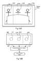
- FIG. 18Ais a block diagram of another specific embodiment of the invention where the camera 1015 captures a scene 1350 .
- the captured scene 1350is digitized and processed into a digitized scene data 1360 as shown in FIG. 18B .
- three focus areas 1352 , 1354 , and 1356 in the scene 1350are shown for purposes of describing an operation of an embodiment of the invention. However, the number of focus areas may also be increased or decreased in various amount. Assume further that objects 1362 , 1364 , and 1366 are within focus areas 1352 , 1354 , and 1356 , respectively.
- a conventional cameracan typically only focus on one of the focus areas 1352 , 1354 , and 1356 , and will require movement in order to shift from one focus area (e.g., area 1352 ) to another focus area (e.g., area 1354 ).
- the conventional video cameramay only be able to focus on the individual within focus area 1352 but not focus on the individuals within focus areas 1354 and 1356 unless the camera is physically steered to the focus area, or unless a second video camera is placed in the room to capture the other focus areas that are not captured by the first video camera.
- the camera 1015can capture focus areas 1352 , 1354 , and 1356 without requiring movement of the camera 1015 .
- a first subset 1368 of the digitized scene data 1360is first selected by webcam engine 410 ( FIG. 4 ), while a second subset 1370 and a third subset 1372 in the digitized scene data 1360 are then selected serially by the webcam engine 410 .
- the first subset 1368corresponds to the focus area 1352 with object 1362 .
- the second subset 1370corresponds to the focus area 1354 with object 1364 .
- the third subset 1372corresponds to the focus area 1356 with object 1366 .
- the selected subsets 1368 , 1370 , and 1370may be skew corrected (e.g., distortion compensated) and may be transmitted to a destination.
- the subsets 1368 , 1370 , and 1372 in digitized scene data 1360are serially selected or sampled.
- the subsets 1368 , 1370 , and 1372are then reconstructed by use of an image reconstruction stage 1374 .
- the output of the image reconstruction stage 1374is an output image 1376 which include images of all objects in the captured focus areas 1352 , 1354 , and 1356 of scene 1350 .
- this specific embodiment of the invention shown in FIGS. 18A and 18Badvantageously permits a wide focus area in a scene to be captured by a single camera, without requiring physical movement of the camera.
- this specific embodimentmay permit a single camera to simulate multiple virtual cameras, since images from multiple focus areas can be serially captured and integrated into a single, integrated output image 1376 . It is noted, as similarly described below, that the subsets 1368 , 1370 , and 1372 may be transmitted to a destination device prior to being reconstructed into the single, integrated output image 1376 . The transmission of the subsets 1368 , 1370 , and 1372 may be performed serially.
- FIGS. 19A and 19Bare block diagrams showing the transmission of the compensated scene subset data 1320 , 1325 , and 1330 to a destination device 1400 such as a server, printer, or computer.
- a destination device 1400such as a server, printer, or computer.
- the advantage of transmitting the composite data 1320 , 1325 , and 1330 as separate viewsis in the savings of bandwidth.
- the composite data 1320 , 1325 , and 1330may be processed in and may be transmitted from the camera 1015 to the destination device 1400 .
- the composite data 1320 , 1325 , and 1330may be transmitted serially.
- subset data 1320 , 1325 , and 1330are shown as examples for describing an operation of a specific embodiment of the invention. Thus, any number of subset data may be transmitted in the operations shown in FIGS. 19A and 19B .
- the composite data 1320 , 1325 , and 1330may be received and stored in frame buffer(s) 1405 , and a processor (or image reconstruction stage) 1410 may be used to reconstruct the composite data 1320 , 1325 , and 1330 into a single image representing the scene captured by the camera 1015 .
- a processoror image reconstruction stage
- FIGS. 19A and 19BFor purposes of clarity and describing the functionality of an embodiment of the invention, other known components that are used for image reconstruction have been omitted in FIGS. 19A and 19B .
- the composite data 1320 , 1325 , and 1330may also be processed in a customer premise equipment 1415 (e.g., a set top box or companion box), and the composite data 1320 , 1325 , and 1330 may be transmitted from the customer premise equipment 1415 to the destination device 1400 .
- the composite data 1320 , 1325 , and 1330may be transmitted serially.
- FIG. 20is a flowchart of a method to perform a panning, tilting or zooming function according to another embodiment of the invention.
- a sceneis captured ( 1500 ) in the field of vision of a camera lens.
- the captured scene in the vision fieldis then stored ( 1505 ) as scene image data in an image collection array.
- the scene image data in the image collection arrayis then processed and stored ( 1510 ) as a digitized scene image data.
- a plurality of subsets of the digitized scene image datais then selected ( 1515 ). For example, a first subset of the digitized scene image data may be selected based on pan/tilt/zoom command(s), while a second subset may be selected based on motion detection techniques. Distortion compensation and compression may then be performed ( 1520 ) on the subsets of the digitized scene image data.
- the distortion-compensated and compressed subsetmay then be transmitted ( 1525 ) to a selected destination such as a destination device.
- webcam 100may comprise a processor and perform the selection of the subset of the digitized scene image data and the distortion compensation and compression of the subset instead of STB 140 .
- the webcam 100can send the digitized scene image output to a processing device, such as a personal computer instead of the STB 140 , and the processing device can select the subset of the digitized scene image data and perform the distortion compensation and compression of the subset.
- the webcam 100can instead send the digitized scene image output to an optional companion box device 175 ( FIG. 1 ) instead of sending the digitized scene image output to the set top box 140 .
- the companion box 175may include, for example, the functionality of an Interactive Companion Box, as described in U.S. patent application Ser. No. 09/815,953, filed on Mar. 22, 2001, entitled “Interactive Companion Set Top Box,” by inventors Ted M. Tsuchida and James A. Bilimaier, the disclosure of which is hereby incorporated by reference.
- Functions of the Interactive Companion Boxmay include Internet access, Video-on-Demand, an electronic programming guide, videoconferencing, and/or other functions.
- sample stage 245 in FIG. 1may instead perform the selection of the image subset to be compressed and compensated for distortion, instead of the webcam engine 410 .
- At least some of the components of this inventionmay be implemented by using a programmed general purpose digital computer, by using application specific integrated circuits or field programmable gate arrays, or by using a network of interconnected components and circuits. Connections may be wired, wireless, by modem, and the like.
Landscapes
- Engineering & Computer Science (AREA)
- Multimedia (AREA)
- Signal Processing (AREA)
- Physics & Mathematics (AREA)
- General Physics & Mathematics (AREA)
- Theoretical Computer Science (AREA)
- Studio Devices (AREA)
- Image Processing (AREA)
- Stereoscopic And Panoramic Photography (AREA)
Abstract
Description
Claims (18)
Priority Applications (1)
| Application Number | Priority Date | Filing Date | Title |
|---|---|---|---|
| US11/428,525US7593041B2 (en) | 2001-03-30 | 2006-07-03 | System and method for a software steerable web camera with multiple image subset capture |
Applications Claiming Priority (3)
| Application Number | Priority Date | Filing Date | Title |
|---|---|---|---|
| US09/823,804US20020141657A1 (en) | 2001-03-30 | 2001-03-30 | System and method for a software steerable web Camera |
| US09/923,820US7071968B2 (en) | 2001-03-30 | 2001-08-06 | System and method for a software steerable web camera with multiple image subset capture |
| US11/428,525US7593041B2 (en) | 2001-03-30 | 2006-07-03 | System and method for a software steerable web camera with multiple image subset capture |
Related Parent Applications (1)
| Application Number | Title | Priority Date | Filing Date |
|---|---|---|---|
| US09/923,820ContinuationUS7071968B2 (en) | 2001-03-30 | 2001-08-06 | System and method for a software steerable web camera with multiple image subset capture |
Publications (2)
| Publication Number | Publication Date |
|---|---|
| US20070030353A1 US20070030353A1 (en) | 2007-02-08 |
| US7593041B2true US7593041B2 (en) | 2009-09-22 |
Family
ID=27124762
Family Applications (1)
| Application Number | Title | Priority Date | Filing Date |
|---|---|---|---|
| US11/428,525Expired - LifetimeUS7593041B2 (en) | 2001-03-30 | 2006-07-03 | System and method for a software steerable web camera with multiple image subset capture |
Country Status (2)
| Country | Link |
|---|---|
| US (1) | US7593041B2 (en) |
| WO (1) | WO2002080521A2 (en) |
Cited By (11)
| Publication number | Priority date | Publication date | Assignee | Title |
|---|---|---|---|---|
| US20080170133A1 (en)* | 2007-01-17 | 2008-07-17 | Asustek Computer Inc. | Video processing method and system for a virtual camera |
| US20080218606A1 (en)* | 2007-03-08 | 2008-09-11 | Sony Corporation | Image processing device, camera device, image processing method, and program |
| US20090010634A1 (en)* | 2007-07-05 | 2009-01-08 | Canon Kabushiki Kaisha | Control device and method for camera unit and program for implementing the control method |
| US20110234475A1 (en)* | 2010-03-25 | 2011-09-29 | Hiroshi Endo | Head-mounted display device |
| US9412149B2 (en) | 2011-02-10 | 2016-08-09 | Panasonic Intellectual Property Management Co., Ltd. | Display device, computer program, and computer-implemented method |
| US20190005709A1 (en)* | 2017-06-30 | 2019-01-03 | Apple Inc. | Techniques for Correction of Visual Artifacts in Multi-View Images |
| US10754242B2 (en) | 2017-06-30 | 2020-08-25 | Apple Inc. | Adaptive resolution and projection format in multi-direction video |
| US10924747B2 (en) | 2017-02-27 | 2021-02-16 | Apple Inc. | Video coding techniques for multi-view video |
| US10999602B2 (en) | 2016-12-23 | 2021-05-04 | Apple Inc. | Sphere projected motion estimation/compensation and mode decision |
| US11093752B2 (en) | 2017-06-02 | 2021-08-17 | Apple Inc. | Object tracking in multi-view video |
| US11259046B2 (en) | 2017-02-15 | 2022-02-22 | Apple Inc. | Processing of equirectangular object data to compensate for distortion by spherical projections |
Families Citing this family (9)
| Publication number | Priority date | Publication date | Assignee | Title |
|---|---|---|---|---|
| US20120259240A1 (en)* | 2011-04-08 | 2012-10-11 | Nviso Sarl | Method and System for Assessing and Measuring Emotional Intensity to a Stimulus |
| US9413941B2 (en)* | 2011-12-20 | 2016-08-09 | Motorola Solutions, Inc. | Methods and apparatus to compensate for overshoot of a desired field of vision by a remotely-controlled image capture device |
| DE102012002277A1 (en)* | 2012-02-06 | 2013-08-08 | Hans Kilian Fremmer | Web cam for use in personal computer, has covering or automatic closure which is provided so as to cover lenses of web cams, and is absolutely certain so that third parties are noticed through web cam |
| US10027873B2 (en) | 2014-11-18 | 2018-07-17 | The Invention Science Fund Ii, Llc | Devices, methods and systems for visual imaging arrays |
| US20190028721A1 (en)* | 2014-11-18 | 2019-01-24 | Elwha Llc | Imaging device system with edge processing |
| US10609270B2 (en) | 2014-11-18 | 2020-03-31 | The Invention Science Fund Ii, Llc | Devices, methods and systems for visual imaging arrays |
| US9942583B2 (en) | 2014-11-18 | 2018-04-10 | The Invention Science Fund Ii, Llc | Devices, methods and systems for multi-user capable visual imaging arrays |
| US9924109B2 (en) | 2014-11-18 | 2018-03-20 | The Invention Science Fund Ii, Llc | Devices, methods, and systems for visual imaging arrays |
| WO2016081630A1 (en)* | 2014-11-18 | 2016-05-26 | Brav Ehren J | Devices, methods and systems for visual imaging arrays |
Citations (32)
| Publication number | Priority date | Publication date | Assignee | Title |
|---|---|---|---|---|
| US4310222A (en) | 1976-10-29 | 1982-01-12 | Canon Kabushiki Kaisha | Retro-focus type wide angle lens |
| US4772107A (en) | 1986-11-05 | 1988-09-20 | The Perkin-Elmer Corporation | Wide angle lens with improved flat field characteristics |
| US4831438A (en) | 1987-02-25 | 1989-05-16 | Household Data Services | Electronic surveillance system |
| US5128776A (en) | 1989-06-16 | 1992-07-07 | Harris Corporation | Prioritized image transmission system and method |
| US5185667A (en) | 1991-05-13 | 1993-02-09 | Telerobotics International, Inc. | Omniview motionless camera orientation system |
| US5353392A (en) | 1990-04-11 | 1994-10-04 | Multi Media Techniques | Method and device for modifying a zone in successive images |
| US5444478A (en) | 1992-12-29 | 1995-08-22 | U.S. Philips Corporation | Image processing method and device for constructing an image from adjacent images |
| US5606364A (en) | 1994-03-30 | 1997-02-25 | Samsung Aerospace Industries, Ltd. | Surveillance system for processing a plurality of signals with a single processor |
| US5657073A (en) | 1995-06-01 | 1997-08-12 | Panoramic Viewing Systems, Inc. | Seamless multi-camera panoramic imaging with distortion correction and selectable field of view |
| US5877821A (en) | 1997-01-30 | 1999-03-02 | Motorola, Inc. | Multimedia input and control apparatus and method for multimedia communications |
| US6005611A (en) | 1994-05-27 | 1999-12-21 | Be Here Corporation | Wide-angle image dewarping method and apparatus |
| US6011558A (en) | 1997-09-23 | 2000-01-04 | Industrial Technology Research Institute | Intelligent stitcher for panoramic image-based virtual worlds |
| WO2000007341A1 (en) | 1998-07-31 | 2000-02-10 | Flashpoint Technology, Inc. | Internet camera gateway |
| US6031540A (en) | 1995-11-02 | 2000-02-29 | Imove Inc. | Method and apparatus for simulating movement in multidimensional space with polygonal projections from subhemispherical imagery |
| US6043837A (en)* | 1997-05-08 | 2000-03-28 | Be Here Corporation | Method and apparatus for electronically distributing images from a panoptic camera system |
| US6052509A (en) | 1996-03-22 | 2000-04-18 | Canon Kabushiki Kaisha | Image pickup apparatus |
| US6128033A (en) | 1996-06-28 | 2000-10-03 | At&T Corporation | Audiovisual communications terminal apparatus for teleconferencing and method |
| US6144773A (en) | 1996-02-27 | 2000-11-07 | Interval Research Corporation | Wavelet-based data compression |
| US6172707B1 (en) | 1992-06-22 | 2001-01-09 | Canon Kabushiki Kaisha | Image pickup device |
| US6223213B1 (en) | 1998-07-31 | 2001-04-24 | Webtv Networks, Inc. | Browser-based email system with user interface for audio/video capture |
| US20010019355A1 (en) | 1997-04-21 | 2001-09-06 | Masakazu Koyanagi | Controller for photographing apparatus and photographing system |
| US6297846B1 (en)* | 1996-05-30 | 2001-10-02 | Fujitsu Limited | Display control system for videoconference terminals |
| US6308015B1 (en) | 1999-06-18 | 2001-10-23 | Olympus Optical Co., Ltd. | Camera having automatic focusing device |
| US6366311B1 (en) | 1996-10-11 | 2002-04-02 | David A. Monroe | Record and playback system for aircraft |
| US6470498B1 (en)* | 1995-02-23 | 2002-10-22 | Motorola, Inc. | Personal computer system, compact disk and method for interactively viewing the earth |
| US6507366B1 (en)* | 1998-04-16 | 2003-01-14 | Samsung Electronics Co., Ltd. | Method and apparatus for automatically tracking a moving object |
| US20030025803A1 (en)* | 1996-11-15 | 2003-02-06 | Shuichi Nakamura | Image processing apparatus and method, storage medium, and communication system |
| US6543052B1 (en)* | 1999-07-09 | 2003-04-01 | Fujitsu Limited | Internet shopping system utilizing set top box and voice recognition |
| US6567121B1 (en)* | 1996-10-25 | 2003-05-20 | Canon Kabushiki Kaisha | Camera control system, camera server, camera client, control method, and storage medium |
| US6606422B1 (en)* | 1999-04-22 | 2003-08-12 | Symah Vision | Method and apparatus for processing and recovering images |
| US6727940B1 (en)* | 1998-07-31 | 2004-04-27 | Canon Kabushiki Kaisha | Image distributing system |
| US7071968B2 (en)* | 2001-03-30 | 2006-07-04 | Digeo, Inc. | System and method for a software steerable web camera with multiple image subset capture |
Family Cites Families (1)
| Publication number | Priority date | Publication date | Assignee | Title |
|---|---|---|---|---|
| US5359363A (en)* | 1991-05-13 | 1994-10-25 | Telerobotics International, Inc. | Omniview motionless camera surveillance system |
- 2002
- 2002-03-04WOPCT/US2002/006561patent/WO2002080521A2/ennot_activeApplication Discontinuation
- 2006
- 2006-07-03USUS11/428,525patent/US7593041B2/ennot_activeExpired - Lifetime
Patent Citations (32)
| Publication number | Priority date | Publication date | Assignee | Title |
|---|---|---|---|---|
| US4310222A (en) | 1976-10-29 | 1982-01-12 | Canon Kabushiki Kaisha | Retro-focus type wide angle lens |
| US4772107A (en) | 1986-11-05 | 1988-09-20 | The Perkin-Elmer Corporation | Wide angle lens with improved flat field characteristics |
| US4831438A (en) | 1987-02-25 | 1989-05-16 | Household Data Services | Electronic surveillance system |
| US5128776A (en) | 1989-06-16 | 1992-07-07 | Harris Corporation | Prioritized image transmission system and method |
| US5353392A (en) | 1990-04-11 | 1994-10-04 | Multi Media Techniques | Method and device for modifying a zone in successive images |
| US5185667A (en) | 1991-05-13 | 1993-02-09 | Telerobotics International, Inc. | Omniview motionless camera orientation system |
| US6172707B1 (en) | 1992-06-22 | 2001-01-09 | Canon Kabushiki Kaisha | Image pickup device |
| US5444478A (en) | 1992-12-29 | 1995-08-22 | U.S. Philips Corporation | Image processing method and device for constructing an image from adjacent images |
| US5606364A (en) | 1994-03-30 | 1997-02-25 | Samsung Aerospace Industries, Ltd. | Surveillance system for processing a plurality of signals with a single processor |
| US6005611A (en) | 1994-05-27 | 1999-12-21 | Be Here Corporation | Wide-angle image dewarping method and apparatus |
| US6470498B1 (en)* | 1995-02-23 | 2002-10-22 | Motorola, Inc. | Personal computer system, compact disk and method for interactively viewing the earth |
| US5657073A (en) | 1995-06-01 | 1997-08-12 | Panoramic Viewing Systems, Inc. | Seamless multi-camera panoramic imaging with distortion correction and selectable field of view |
| US6031540A (en) | 1995-11-02 | 2000-02-29 | Imove Inc. | Method and apparatus for simulating movement in multidimensional space with polygonal projections from subhemispherical imagery |
| US6144773A (en) | 1996-02-27 | 2000-11-07 | Interval Research Corporation | Wavelet-based data compression |
| US6052509A (en) | 1996-03-22 | 2000-04-18 | Canon Kabushiki Kaisha | Image pickup apparatus |
| US6297846B1 (en)* | 1996-05-30 | 2001-10-02 | Fujitsu Limited | Display control system for videoconference terminals |
| US6128033A (en) | 1996-06-28 | 2000-10-03 | At&T Corporation | Audiovisual communications terminal apparatus for teleconferencing and method |
| US6366311B1 (en) | 1996-10-11 | 2002-04-02 | David A. Monroe | Record and playback system for aircraft |
| US6567121B1 (en)* | 1996-10-25 | 2003-05-20 | Canon Kabushiki Kaisha | Camera control system, camera server, camera client, control method, and storage medium |
| US20030025803A1 (en)* | 1996-11-15 | 2003-02-06 | Shuichi Nakamura | Image processing apparatus and method, storage medium, and communication system |
| US5877821A (en) | 1997-01-30 | 1999-03-02 | Motorola, Inc. | Multimedia input and control apparatus and method for multimedia communications |
| US20010019355A1 (en) | 1997-04-21 | 2001-09-06 | Masakazu Koyanagi | Controller for photographing apparatus and photographing system |
| US6043837A (en)* | 1997-05-08 | 2000-03-28 | Be Here Corporation | Method and apparatus for electronically distributing images from a panoptic camera system |
| US6011558A (en) | 1997-09-23 | 2000-01-04 | Industrial Technology Research Institute | Intelligent stitcher for panoramic image-based virtual worlds |
| US6507366B1 (en)* | 1998-04-16 | 2003-01-14 | Samsung Electronics Co., Ltd. | Method and apparatus for automatically tracking a moving object |
| WO2000007341A1 (en) | 1998-07-31 | 2000-02-10 | Flashpoint Technology, Inc. | Internet camera gateway |
| US6223213B1 (en) | 1998-07-31 | 2001-04-24 | Webtv Networks, Inc. | Browser-based email system with user interface for audio/video capture |
| US6727940B1 (en)* | 1998-07-31 | 2004-04-27 | Canon Kabushiki Kaisha | Image distributing system |
| US6606422B1 (en)* | 1999-04-22 | 2003-08-12 | Symah Vision | Method and apparatus for processing and recovering images |
| US6308015B1 (en) | 1999-06-18 | 2001-10-23 | Olympus Optical Co., Ltd. | Camera having automatic focusing device |
| US6543052B1 (en)* | 1999-07-09 | 2003-04-01 | Fujitsu Limited | Internet shopping system utilizing set top box and voice recognition |
| US7071968B2 (en)* | 2001-03-30 | 2006-07-04 | Digeo, Inc. | System and method for a software steerable web camera with multiple image subset capture |
Non-Patent Citations (12)
| Title |
|---|
| Company News. iMove granted new patent for panoramic imaging: The patent extends iMove's intellectual property in panoramic image seaming. Webpage [online]. iMove Incorporated, Mar. 25, 2000 [retrieved on Mar. 26, 2000]. Retrieved from the Internet: <URL:http://www.smoothmove.com/0lcompany-info/.html>. |
| Internet monitoring, live streaming video, and webcam software from Surveyor Corporation. Webpage [online]. Surveyor Corporation, 2001 [retrieved on Oct. 11, 2001]. Retrieved from the Internet: <URL:http://www.surveyorcorp.com/products/productsinfo.html>. |
| Ken Turkowski, Making Environment Maps From Fisheye Photographs, [online], [retrieved on Oct. 10, 2001]. Retrieved from the Internet: <URL: http://www.iqtvra.org./Defish/Fisheye.html>. |
| Leegomes. BeHere takes a 360-degree Turn in Imaging. Press Releases [online], [retrieved on Oct. 11, 2001]. Retrieved from the Internet: <URL:http://www.BeHere.com/news-press-031501.html>. |
| Office Action Mailed Aug. 26, 2005, for U.S. Appl. No. 09/923,820, filed Aug. 6, 2001. |
| Office Action Mailed Feb. 8, 2005, for U.S. Appl. No. 09/923,820, filed Aug. 6, 2001. |
| Office Action Mailed Oct. 20, 2004, for U.S. Appl. No. 09/823,804, filed Mar. 30, 2001. |
| Panoscan Home. Panoscan offers a choice of new cameras! Webpage [online]. Panoscan, Inc., 2001 [retrieved on Oct. 10, 2001]. Retrieved from the Internet: <URL:http://www.panoscan.com>. |
| Product Selector, Product Overview/Selector. Webpage [online]. Surveyor Corporation, 2001. [retreived on Oct. 10, 2001]. Retrieved from the Internet: <URL:http://www.dazzle.com/products/selectgut.html>. |
| Products. Webpage [online]. Spheron VR, 2000 [retrieved on Oct. 10, 2001]. Retrieved from the Internet: <URL:http://www.Spheron.com/products/products-portal.html>. |
| Robotic Camera Mounts Info, Transit RCM. Webpage [online]. Surveyor Corporation, 2001 [retrieved on Oct. 10, 2001]. Retrieved from the Internet: <URL:http://www.surveyorcorp.com/products/transittrcm-info.html>. |
| Welcome to BeHere.com. Webpage [online]. BeHere Technologies, 2001 [retrieved on Oct. 10, 2001]. Retrieved from the Internet: <URL:http://www.BeHere.conV1.html>. |
Cited By (15)
| Publication number | Priority date | Publication date | Assignee | Title |
|---|---|---|---|---|
| US20080170133A1 (en)* | 2007-01-17 | 2008-07-17 | Asustek Computer Inc. | Video processing method and system for a virtual camera |
| US20080218606A1 (en)* | 2007-03-08 | 2008-09-11 | Sony Corporation | Image processing device, camera device, image processing method, and program |
| US8289420B2 (en)* | 2007-03-08 | 2012-10-16 | Sony Corporation | Image processing device, camera device, image processing method, and program |
| US20090010634A1 (en)* | 2007-07-05 | 2009-01-08 | Canon Kabushiki Kaisha | Control device and method for camera unit and program for implementing the control method |
| US7965935B2 (en)* | 2007-07-05 | 2011-06-21 | Canon Kabushiki Kaisha | Control device and method for camera unit and program for implementing the control method |
| US20110234475A1 (en)* | 2010-03-25 | 2011-09-29 | Hiroshi Endo | Head-mounted display device |
| US9412149B2 (en) | 2011-02-10 | 2016-08-09 | Panasonic Intellectual Property Management Co., Ltd. | Display device, computer program, and computer-implemented method |
| US11651471B2 (en) | 2011-02-10 | 2023-05-16 | Panasonic Intellectual Property Management Co., Ltd. | Display device, computer program, and computer-implemented method |
| US10999602B2 (en) | 2016-12-23 | 2021-05-04 | Apple Inc. | Sphere projected motion estimation/compensation and mode decision |
| US11818394B2 (en) | 2016-12-23 | 2023-11-14 | Apple Inc. | Sphere projected motion estimation/compensation and mode decision |
| US11259046B2 (en) | 2017-02-15 | 2022-02-22 | Apple Inc. | Processing of equirectangular object data to compensate for distortion by spherical projections |
| US10924747B2 (en) | 2017-02-27 | 2021-02-16 | Apple Inc. | Video coding techniques for multi-view video |
| US11093752B2 (en) | 2017-06-02 | 2021-08-17 | Apple Inc. | Object tracking in multi-view video |
| US20190005709A1 (en)* | 2017-06-30 | 2019-01-03 | Apple Inc. | Techniques for Correction of Visual Artifacts in Multi-View Images |
| US10754242B2 (en) | 2017-06-30 | 2020-08-25 | Apple Inc. | Adaptive resolution and projection format in multi-direction video |
Also Published As
| Publication number | Publication date |
|---|---|
| WO2002080521A2 (en) | 2002-10-10 |
| US20070030353A1 (en) | 2007-02-08 |
| WO2002080521A3 (en) | 2004-06-24 |
Similar Documents
| Publication | Publication Date | Title |
|---|---|---|
| US7071968B2 (en) | System and method for a software steerable web camera with multiple image subset capture | |
| US7593041B2 (en) | System and method for a software steerable web camera with multiple image subset capture | |
| US7450165B2 (en) | Multiple-view processing in wide-angle video camera | |
| US8305424B2 (en) | System, apparatus and method for panorama image display | |
| US6331869B1 (en) | Method and apparatus for electronically distributing motion panoramic images | |
| US10038841B1 (en) | System for streaming multiple regions deriving from a wide-angle camera | |
| US6005613A (en) | Multi-mode digital camera with computer interface using data packets combining image and mode data | |
| KR100986228B1 (en) | Camera unit and image record playback method | |
| AU2012306862B2 (en) | A system and method for processing a very wide angle image | |
| US20100289904A1 (en) | Video capture device providing multiple resolution video feeds | |
| US20110234807A1 (en) | Digital security camera | |
| JP4804378B2 (en) | Video display device and video display method | |
| US20090040293A1 (en) | Camera Array Apparatus and Method for Capturing Wide-Angle Network Video | |
| EP0908053A1 (en) | Panoramic camera | |
| US20070002131A1 (en) | Dynamic interactive region-of-interest panoramic/three-dimensional immersive communication system and method | |
| JPH08331285A (en) | Image input device | |
| WO2007119712A1 (en) | Camera apparatus, and image processing apparatus and image processing method | |
| JPH0510872B2 (en) | ||
| US11838634B2 (en) | Method of generating a digital video image using a wide-angle field of view lens | |
| KR102009988B1 (en) | Method for compensating image camera system for compensating distortion of lens using super wide angle camera and Transport Video Interface Apparatus used in it | |
| EP1142332A1 (en) | Camera with peripheral vision | |
| Gholmansaraei | HIGH RESOLUTION EYE TRACKING CAMERA ENABLING A FOVEATED IMAGING FOR VIDEO COLLABORATION DEVICES | |
| JPH08279999A (en) | Video conference multimedia system | |
| US20070036536A1 (en) | Electronic apparatus with adjustable charge couple device | |
| JPH01300789A (en) | Direction control system for camera in video telephone equipment |
Legal Events
| Date | Code | Title | Description |
|---|---|---|---|
| STCF | Information on status: patent grant | Free format text:PATENTED CASE | |
| CC | Certificate of correction | ||
| AS | Assignment | Owner name:ARRIS GROUP, INC., GEORGIA Free format text:ASSIGNMENT OF ASSIGNORS INTEREST;ASSIGNOR:DIGEO, INC AND VULCAN VENTURES, INC.;REEL/FRAME:026621/0258 Effective date:20090922 | |
| FPAY | Fee payment | Year of fee payment:4 | |
| AS | Assignment | Owner name:ARRIS ENTERPRISES, INC., GEORGIA Free format text:MERGER;ASSIGNOR:ARRIS GROUP, INC.;REEL/FRAME:030228/0349 Effective date:20130416 | |
| AS | Assignment | Owner name:BANK OF AMERICA, N.A., AS ADMINISTRATIVE AGENT, IL Free format text:SECURITY AGREEMENT;ASSIGNORS:ARRIS GROUP, INC.;ARRIS ENTERPRISES, INC.;ARRIS SOLUTIONS, INC.;AND OTHERS;REEL/FRAME:030498/0023 Effective date:20130417 Owner name:BANK OF AMERICA, N.A., AS ADMINISTRATIVE AGENT, ILLINOIS Free format text:SECURITY AGREEMENT;ASSIGNORS:ARRIS GROUP, INC.;ARRIS ENTERPRISES, INC.;ARRIS SOLUTIONS, INC.;AND OTHERS;REEL/FRAME:030498/0023 Effective date:20130417 | |
| AS | Assignment | Owner name:ARRIS ENTERPRISES LLC, PENNSYLVANIA Free format text:CHANGE OF NAME;ASSIGNOR:ARRIS ENTERPRISES INC;REEL/FRAME:041995/0031 Effective date:20151231 | |
| FPAY | Fee payment | Year of fee payment:8 | |
| AS | Assignment | Owner name:ARRIS KOREA, INC., PENNSYLVANIA Free format text:TERMINATION AND RELEASE OF SECURITY INTEREST IN PATENTS;ASSIGNOR:BANK OF AMERICA, N.A., AS ADMINISTRATIVE AGENT;REEL/FRAME:048825/0294 Effective date:20190404 Owner name:NEXTLEVEL SYSTEMS (PUERTO RICO), INC., PENNSYLVANI Free format text:TERMINATION AND RELEASE OF SECURITY INTEREST IN PATENTS;ASSIGNOR:BANK OF AMERICA, N.A., AS ADMINISTRATIVE AGENT;REEL/FRAME:048825/0294 Effective date:20190404 Owner name:GENERAL INSTRUMENT INTERNATIONAL HOLDINGS, INC., P Free format text:TERMINATION AND RELEASE OF SECURITY INTEREST IN PATENTS;ASSIGNOR:BANK OF AMERICA, N.A., AS ADMINISTRATIVE AGENT;REEL/FRAME:048825/0294 Effective date:20190404 Owner name:SETJAM, INC., PENNSYLVANIA Free format text:TERMINATION AND RELEASE OF SECURITY INTEREST IN PATENTS;ASSIGNOR:BANK OF AMERICA, N.A., AS ADMINISTRATIVE AGENT;REEL/FRAME:048825/0294 Effective date:20190404 Owner name:BIG BAND NETWORKS, INC., PENNSYLVANIA Free format text:TERMINATION AND RELEASE OF SECURITY INTEREST IN PATENTS;ASSIGNOR:BANK OF AMERICA, N.A., AS ADMINISTRATIVE AGENT;REEL/FRAME:048825/0294 Effective date:20190404 Owner name:GIC INTERNATIONAL CAPITAL LLC, PENNSYLVANIA Free format text:TERMINATION AND RELEASE OF SECURITY INTEREST IN PATENTS;ASSIGNOR:BANK OF AMERICA, N.A., AS ADMINISTRATIVE AGENT;REEL/FRAME:048825/0294 Effective date:20190404 Owner name:THE GI REALTY TRUST 1996, PENNSYLVANIA Free format text:TERMINATION AND RELEASE OF SECURITY INTEREST IN PATENTS;ASSIGNOR:BANK OF AMERICA, N.A., AS ADMINISTRATIVE AGENT;REEL/FRAME:048825/0294 Effective date:20190404 Owner name:BROADBUS TECHNOLOGIES, INC., PENNSYLVANIA Free format text:TERMINATION AND RELEASE OF SECURITY INTEREST IN PATENTS;ASSIGNOR:BANK OF AMERICA, N.A., AS ADMINISTRATIVE AGENT;REEL/FRAME:048825/0294 Effective date:20190404 Owner name:GIC INTERNATIONAL HOLDCO LLC, PENNSYLVANIA Free format text:TERMINATION AND RELEASE OF SECURITY INTEREST IN PATENTS;ASSIGNOR:BANK OF AMERICA, N.A., AS ADMINISTRATIVE AGENT;REEL/FRAME:048825/0294 Effective date:20190404 Owner name:ARRIS HOLDINGS CORP. OF ILLINOIS, INC., PENNSYLVAN Free format text:TERMINATION AND RELEASE OF SECURITY INTEREST IN PATENTS;ASSIGNOR:BANK OF AMERICA, N.A., AS ADMINISTRATIVE AGENT;REEL/FRAME:048825/0294 Effective date:20190404 Owner name:LEAPSTONE SYSTEMS, INC., PENNSYLVANIA Free format text:TERMINATION AND RELEASE OF SECURITY INTEREST IN PATENTS;ASSIGNOR:BANK OF AMERICA, N.A., AS ADMINISTRATIVE AGENT;REEL/FRAME:048825/0294 Effective date:20190404 Owner name:SUNUP DESIGN SYSTEMS, INC., PENNSYLVANIA Free format text:TERMINATION AND RELEASE OF SECURITY INTEREST IN PATENTS;ASSIGNOR:BANK OF AMERICA, N.A., AS ADMINISTRATIVE AGENT;REEL/FRAME:048825/0294 Effective date:20190404 Owner name:QUANTUM BRIDGE COMMUNICATIONS, INC., PENNSYLVANIA Free format text:TERMINATION AND RELEASE OF SECURITY INTEREST IN PATENTS;ASSIGNOR:BANK OF AMERICA, N.A., AS ADMINISTRATIVE AGENT;REEL/FRAME:048825/0294 Effective date:20190404 Owner name:UCENTRIC SYSTEMS, INC., PENNSYLVANIA Free format text:TERMINATION AND RELEASE OF SECURITY INTEREST IN PATENTS;ASSIGNOR:BANK OF AMERICA, N.A., AS ADMINISTRATIVE AGENT;REEL/FRAME:048825/0294 Effective date:20190404 Owner name:MOTOROLA WIRELINE NETWORKS, INC., PENNSYLVANIA Free format text:TERMINATION AND RELEASE OF SECURITY INTEREST IN PATENTS;ASSIGNOR:BANK OF AMERICA, N.A., AS ADMINISTRATIVE AGENT;REEL/FRAME:048825/0294 Effective date:20190404 Owner name:MODULUS VIDEO, INC., PENNSYLVANIA Free format text:TERMINATION AND RELEASE OF SECURITY INTEREST IN PATENTS;ASSIGNOR:BANK OF AMERICA, N.A., AS ADMINISTRATIVE AGENT;REEL/FRAME:048825/0294 Effective date:20190404 Owner name:ARRIS GROUP, INC., PENNSYLVANIA Free format text:TERMINATION AND RELEASE OF SECURITY INTEREST IN PATENTS;ASSIGNOR:BANK OF AMERICA, N.A., AS ADMINISTRATIVE AGENT;REEL/FRAME:048825/0294 Effective date:20190404 Owner name:ARRIS SOLUTIONS, INC., PENNSYLVANIA Free format text:TERMINATION AND RELEASE OF SECURITY INTEREST IN PATENTS;ASSIGNOR:BANK OF AMERICA, N.A., AS ADMINISTRATIVE AGENT;REEL/FRAME:048825/0294 Effective date:20190404 Owner name:JERROLD DC RADIO, INC., PENNSYLVANIA Free format text:TERMINATION AND RELEASE OF SECURITY INTEREST IN PATENTS;ASSIGNOR:BANK OF AMERICA, N.A., AS ADMINISTRATIVE AGENT;REEL/FRAME:048825/0294 Effective date:20190404 Owner name:AEROCAST, INC., PENNSYLVANIA Free format text:TERMINATION AND RELEASE OF SECURITY INTEREST IN PATENTS;ASSIGNOR:BANK OF AMERICA, N.A., AS ADMINISTRATIVE AGENT;REEL/FRAME:048825/0294 Effective date:20190404 Owner name:CCE SOFTWARE LLC, PENNSYLVANIA Free format text:TERMINATION AND RELEASE OF SECURITY INTEREST IN PATENTS;ASSIGNOR:BANK OF AMERICA, N.A., AS ADMINISTRATIVE AGENT;REEL/FRAME:048825/0294 Effective date:20190404 Owner name:TEXSCAN CORPORATION, PENNSYLVANIA Free format text:TERMINATION AND RELEASE OF SECURITY INTEREST IN PATENTS;ASSIGNOR:BANK OF AMERICA, N.A., AS ADMINISTRATIVE AGENT;REEL/FRAME:048825/0294 Effective date:20190404 Owner name:POWER GUARD, INC., PENNSYLVANIA Free format text:TERMINATION AND RELEASE OF SECURITY INTEREST IN PATENTS;ASSIGNOR:BANK OF AMERICA, N.A., AS ADMINISTRATIVE AGENT;REEL/FRAME:048825/0294 Effective date:20190404 Owner name:GENERAL INSTRUMENT AUTHORIZATION SERVICES, INC., P Free format text:TERMINATION AND RELEASE OF SECURITY INTEREST IN PATENTS;ASSIGNOR:BANK OF AMERICA, N.A., AS ADMINISTRATIVE AGENT;REEL/FRAME:048825/0294 Effective date:20190404 Owner name:ARRIS ENTERPRISES, INC., PENNSYLVANIA Free format text:TERMINATION AND RELEASE OF SECURITY INTEREST IN PATENTS;ASSIGNOR:BANK OF AMERICA, N.A., AS ADMINISTRATIVE AGENT;REEL/FRAME:048825/0294 Effective date:20190404 Owner name:GENERAL INSTRUMENT CORPORATION, PENNSYLVANIA Free format text:TERMINATION AND RELEASE OF SECURITY INTEREST IN PATENTS;ASSIGNOR:BANK OF AMERICA, N.A., AS ADMINISTRATIVE AGENT;REEL/FRAME:048825/0294 Effective date:20190404 Owner name:NETOPIA, INC., PENNSYLVANIA Free format text:TERMINATION AND RELEASE OF SECURITY INTEREST IN PATENTS;ASSIGNOR:BANK OF AMERICA, N.A., AS ADMINISTRATIVE AGENT;REEL/FRAME:048825/0294 Effective date:20190404 Owner name:4HOME, INC., PENNSYLVANIA Free format text:TERMINATION AND RELEASE OF SECURITY INTEREST IN PATENTS;ASSIGNOR:BANK OF AMERICA, N.A., AS ADMINISTRATIVE AGENT;REEL/FRAME:048825/0294 Effective date:20190404 Owner name:IMEDIA CORPORATION, PENNSYLVANIA Free format text:TERMINATION AND RELEASE OF SECURITY INTEREST IN PATENTS;ASSIGNOR:BANK OF AMERICA, N.A., AS ADMINISTRATIVE AGENT;REEL/FRAME:048825/0294 Effective date:20190404 Owner name:ACADIA AIC, INC., PENNSYLVANIA Free format text:TERMINATION AND RELEASE OF SECURITY INTEREST IN PATENTS;ASSIGNOR:BANK OF AMERICA, N.A., AS ADMINISTRATIVE AGENT;REEL/FRAME:048825/0294 Effective date:20190404 Owner name:GENERAL INSTRUMENT INTERNATIONAL HOLDINGS, INC., PENNSYLVANIA Free format text:TERMINATION AND RELEASE OF SECURITY INTEREST IN PATENTS;ASSIGNOR:BANK OF AMERICA, N.A., AS ADMINISTRATIVE AGENT;REEL/FRAME:048825/0294 Effective date:20190404 Owner name:NEXTLEVEL SYSTEMS (PUERTO RICO), INC., PENNSYLVANIA Free format text:TERMINATION AND RELEASE OF SECURITY INTEREST IN PATENTS;ASSIGNOR:BANK OF AMERICA, N.A., AS ADMINISTRATIVE AGENT;REEL/FRAME:048825/0294 Effective date:20190404 Owner name:ARRIS HOLDINGS CORP. OF ILLINOIS, INC., PENNSYLVANIA Free format text:TERMINATION AND RELEASE OF SECURITY INTEREST IN PATENTS;ASSIGNOR:BANK OF AMERICA, N.A., AS ADMINISTRATIVE AGENT;REEL/FRAME:048825/0294 Effective date:20190404 Owner name:GENERAL INSTRUMENT AUTHORIZATION SERVICES, INC., PENNSYLVANIA Free format text:TERMINATION AND RELEASE OF SECURITY INTEREST IN PATENTS;ASSIGNOR:BANK OF AMERICA, N.A., AS ADMINISTRATIVE AGENT;REEL/FRAME:048825/0294 Effective date:20190404 | |
| AS | Assignment | Owner name:ARRIS ENTERPRISES LLC, GEORGIA Free format text:CHANGE OF NAME;ASSIGNOR:ARRIS ENTERPRISES, INC.;REEL/FRAME:049586/0470 Effective date:20151231 | |
| AS | Assignment | Owner name:WILMINGTON TRUST, NATIONAL ASSOCIATION, AS COLLATE Free format text:PATENT SECURITY AGREEMENT;ASSIGNOR:ARRIS ENTERPRISES LLC;REEL/FRAME:049820/0495 Effective date:20190404 Owner name:JPMORGAN CHASE BANK, N.A., NEW YORK Free format text:ABL SECURITY AGREEMENT;ASSIGNORS:COMMSCOPE, INC. OF NORTH CAROLINA;COMMSCOPE TECHNOLOGIES LLC;ARRIS ENTERPRISES LLC;AND OTHERS;REEL/FRAME:049892/0396 Effective date:20190404 Owner name:JPMORGAN CHASE BANK, N.A., NEW YORK Free format text:TERM LOAN SECURITY AGREEMENT;ASSIGNORS:COMMSCOPE, INC. OF NORTH CAROLINA;COMMSCOPE TECHNOLOGIES LLC;ARRIS ENTERPRISES LLC;AND OTHERS;REEL/FRAME:049905/0504 Effective date:20190404 Owner name:WILMINGTON TRUST, NATIONAL ASSOCIATION, AS COLLATERAL AGENT, CONNECTICUT Free format text:PATENT SECURITY AGREEMENT;ASSIGNOR:ARRIS ENTERPRISES LLC;REEL/FRAME:049820/0495 Effective date:20190404 | |
| MAFP | Maintenance fee payment | Free format text:PAYMENT OF MAINTENANCE FEE, 12TH YEAR, LARGE ENTITY (ORIGINAL EVENT CODE: M1553); ENTITY STATUS OF PATENT OWNER: LARGE ENTITY Year of fee payment:12 | |
| AS | Assignment | Owner name:WILMINGTON TRUST, DELAWARE Free format text:SECURITY INTEREST;ASSIGNORS:ARRIS SOLUTIONS, INC.;ARRIS ENTERPRISES LLC;COMMSCOPE TECHNOLOGIES LLC;AND OTHERS;REEL/FRAME:060752/0001 Effective date:20211115 | |
| AS | Assignment | Owner name:RUCKUS WIRELESS, LLC (F/K/A RUCKUS WIRELESS, INC.), NORTH CAROLINA Free format text:RELEASE OF SECURITY INTEREST AT REEL/FRAME 049905/0504;ASSIGNOR:JPMORGAN CHASE BANK, N.A., AS COLLATERAL AGENT;REEL/FRAME:071477/0255 Effective date:20241217 Owner name:COMMSCOPE TECHNOLOGIES LLC, NORTH CAROLINA Free format text:RELEASE OF SECURITY INTEREST AT REEL/FRAME 049905/0504;ASSIGNOR:JPMORGAN CHASE BANK, N.A., AS COLLATERAL AGENT;REEL/FRAME:071477/0255 Effective date:20241217 Owner name:COMMSCOPE, INC. OF NORTH CAROLINA, NORTH CAROLINA Free format text:RELEASE OF SECURITY INTEREST AT REEL/FRAME 049905/0504;ASSIGNOR:JPMORGAN CHASE BANK, N.A., AS COLLATERAL AGENT;REEL/FRAME:071477/0255 Effective date:20241217 Owner name:ARRIS SOLUTIONS, INC., NORTH CAROLINA Free format text:RELEASE OF SECURITY INTEREST AT REEL/FRAME 049905/0504;ASSIGNOR:JPMORGAN CHASE BANK, N.A., AS COLLATERAL AGENT;REEL/FRAME:071477/0255 Effective date:20241217 Owner name:ARRIS TECHNOLOGY, INC., NORTH CAROLINA Free format text:RELEASE OF SECURITY INTEREST AT REEL/FRAME 049905/0504;ASSIGNOR:JPMORGAN CHASE BANK, N.A., AS COLLATERAL AGENT;REEL/FRAME:071477/0255 Effective date:20241217 Owner name:ARRIS ENTERPRISES LLC (F/K/A ARRIS ENTERPRISES, INC.), NORTH CAROLINA Free format text:RELEASE OF SECURITY INTEREST AT REEL/FRAME 049905/0504;ASSIGNOR:JPMORGAN CHASE BANK, N.A., AS COLLATERAL AGENT;REEL/FRAME:071477/0255 Effective date:20241217 |