US7593034B2 - Loop recording with book marking - Google Patents
Loop recording with book markingDownload PDFInfo
- Publication number
- US7593034B2 US7593034B2US12/268,286US26828608AUS7593034B2US 7593034 B2US7593034 B2US 7593034B2US 26828608 AUS26828608 AUS 26828608AUS 7593034 B2US7593034 B2US 7593034B2
- Authority
- US
- United States
- Prior art keywords
- recorded
- signal
- write
- protected
- recording
- Prior art date
- Legal status (The legal status is an assumption and is not a legal conclusion. Google has not performed a legal analysis and makes no representation as to the accuracy of the status listed.)
- Active
Links
- 230000015654memoryEffects0.000claimsabstractdescription118
- 239000000872bufferSubstances0.000claimsabstractdescription52
- 238000000034methodMethods0.000claimsdescription14
- 239000011521glassSubstances0.000claimsdescription8
- 230000004044responseEffects0.000claimsdescription5
- 230000005236sound signalEffects0.000claimsdescription3
- 230000005540biological transmissionEffects0.000claims1
- 230000011664signalingEffects0.000description10
- 230000006870functionEffects0.000description9
- 230000008901benefitEffects0.000description4
- 238000005516engineering processMethods0.000description4
- 230000001960triggered effectEffects0.000description4
- 238000010586diagramMethods0.000description3
- 230000033001locomotionEffects0.000description3
- 238000012546transferMethods0.000description3
- 230000009471actionEffects0.000description2
- 238000004891communicationMethods0.000description2
- 230000006835compressionEffects0.000description2
- 238000007906compressionMethods0.000description2
- 238000001514detection methodMethods0.000description2
- 239000000835fiberSubstances0.000description2
- 239000012634fragmentSubstances0.000description2
- 238000003384imaging methodMethods0.000description2
- 239000000463materialSubstances0.000description2
- 230000001755vocal effectEffects0.000description2
- 206010011224CoughDiseases0.000description1
- 230000004913activationEffects0.000description1
- 238000013459approachMethods0.000description1
- 238000003491arrayMethods0.000description1
- 238000013475authorizationMethods0.000description1
- 230000008859changeEffects0.000description1
- 235000019504cigarettesNutrition0.000description1
- 238000012790confirmationMethods0.000description1
- 230000004069differentiationEffects0.000description1
- 239000000428dustSubstances0.000description1
- 230000006353environmental stressEffects0.000description1
- 230000007246mechanismEffects0.000description1
- 238000012986modificationMethods0.000description1
- 230000004048modificationEffects0.000description1
- 238000012544monitoring processMethods0.000description1
- 230000003287optical effectEffects0.000description1
- 238000004806packaging method and processMethods0.000description1
- 238000003825pressingMethods0.000description1
- 230000008569processEffects0.000description1
- 230000001012protectorEffects0.000description1
- 238000001454recorded imageMethods0.000description1
- 239000004065semiconductorSubstances0.000description1
- 230000035939shockEffects0.000description1
- 239000007787solidSubstances0.000description1
- 230000001052transient effectEffects0.000description1
- 238000005303weighingMethods0.000description1
Images


Classifications
- H—ELECTRICITY
- H04—ELECTRIC COMMUNICATION TECHNIQUE
- H04N—PICTORIAL COMMUNICATION, e.g. TELEVISION
- H04N7/00—Television systems
- H04N7/18—Closed-circuit television [CCTV] systems, i.e. systems in which the video signal is not broadcast
- G—PHYSICS
- G11—INFORMATION STORAGE
- G11B—INFORMATION STORAGE BASED ON RELATIVE MOVEMENT BETWEEN RECORD CARRIER AND TRANSDUCER
- G11B23/00—Record carriers not specific to the method of recording or reproducing; Accessories, e.g. containers, specially adapted for co-operation with the recording or reproducing apparatus ; Intermediate mediums; Apparatus or processes specially adapted for their manufacture
- G11B23/28—Indicating or preventing prior or unauthorised use, e.g. cassettes with sealing or locking means, write-protect devices for discs
- G11B23/288—Protecting disks from being written or overwritten
- G—PHYSICS
- G11—INFORMATION STORAGE
- G11B—INFORMATION STORAGE BASED ON RELATIVE MOVEMENT BETWEEN RECORD CARRIER AND TRANSDUCER
- G11B27/00—Editing; Indexing; Addressing; Timing or synchronising; Monitoring; Measuring tape travel
- G11B27/10—Indexing; Addressing; Timing or synchronising; Measuring tape travel
- G—PHYSICS
- G11—INFORMATION STORAGE
- G11B—INFORMATION STORAGE BASED ON RELATIVE MOVEMENT BETWEEN RECORD CARRIER AND TRANSDUCER
- G11B31/00—Arrangements for the associated working of recording or reproducing apparatus with related apparatus
- G11B31/006—Arrangements for the associated working of recording or reproducing apparatus with related apparatus with video camera or receiver
- H—ELECTRICITY
- H04—ELECTRIC COMMUNICATION TECHNIQUE
- H04N—PICTORIAL COMMUNICATION, e.g. TELEVISION
- H04N1/00—Scanning, transmission or reproduction of documents or the like, e.g. facsimile transmission; Details thereof
- H04N1/00127—Connection or combination of a still picture apparatus with another apparatus, e.g. for storage, processing or transmission of still picture signals or of information associated with a still picture
- H—ELECTRICITY
- H04—ELECTRIC COMMUNICATION TECHNIQUE
- H04N—PICTORIAL COMMUNICATION, e.g. TELEVISION
- H04N23/00—Cameras or camera modules comprising electronic image sensors; Control thereof
- H04N23/60—Control of cameras or camera modules
- H04N23/66—Remote control of cameras or camera parts, e.g. by remote control devices
- H04N23/661—Transmitting camera control signals through networks, e.g. control via the Internet
- H—ELECTRICITY
- H04—ELECTRIC COMMUNICATION TECHNIQUE
- H04N—PICTORIAL COMMUNICATION, e.g. TELEVISION
- H04N5/00—Details of television systems
- H04N5/76—Television signal recording
- H—ELECTRICITY
- H04—ELECTRIC COMMUNICATION TECHNIQUE
- H04N—PICTORIAL COMMUNICATION, e.g. TELEVISION
- H04N5/00—Details of television systems
- H04N5/76—Television signal recording
- H04N5/765—Interface circuits between an apparatus for recording and another apparatus
- H04N5/77—Interface circuits between an apparatus for recording and another apparatus between a recording apparatus and a television camera
- G—PHYSICS
- G08—SIGNALLING
- G08B—SIGNALLING OR CALLING SYSTEMS; ORDER TELEGRAPHS; ALARM SYSTEMS
- G08B13/00—Burglar, theft or intruder alarms
- G08B13/18—Actuation by interference with heat, light, or radiation of shorter wavelength; Actuation by intruding sources of heat, light, or radiation of shorter wavelength
- G08B13/189—Actuation by interference with heat, light, or radiation of shorter wavelength; Actuation by intruding sources of heat, light, or radiation of shorter wavelength using passive radiation detection systems
- G08B13/194—Actuation by interference with heat, light, or radiation of shorter wavelength; Actuation by intruding sources of heat, light, or radiation of shorter wavelength using passive radiation detection systems using image scanning and comparing systems
- G08B13/196—Actuation by interference with heat, light, or radiation of shorter wavelength; Actuation by intruding sources of heat, light, or radiation of shorter wavelength using passive radiation detection systems using image scanning and comparing systems using television cameras
- G08B13/19617—Surveillance camera constructional details
- G08B13/19621—Portable camera
- G—PHYSICS
- G08—SIGNALLING
- G08B—SIGNALLING OR CALLING SYSTEMS; ORDER TELEGRAPHS; ALARM SYSTEMS
- G08B13/00—Burglar, theft or intruder alarms
- G08B13/18—Actuation by interference with heat, light, or radiation of shorter wavelength; Actuation by intruding sources of heat, light, or radiation of shorter wavelength
- G08B13/189—Actuation by interference with heat, light, or radiation of shorter wavelength; Actuation by intruding sources of heat, light, or radiation of shorter wavelength using passive radiation detection systems
- G08B13/194—Actuation by interference with heat, light, or radiation of shorter wavelength; Actuation by intruding sources of heat, light, or radiation of shorter wavelength using passive radiation detection systems using image scanning and comparing systems
- G08B13/196—Actuation by interference with heat, light, or radiation of shorter wavelength; Actuation by intruding sources of heat, light, or radiation of shorter wavelength using passive radiation detection systems using image scanning and comparing systems using television cameras
- G08B13/19665—Details related to the storage of video surveillance data
- G08B13/19676—Temporary storage, e.g. cyclic memory, buffer storage on pre-alarm
- G—PHYSICS
- G08—SIGNALLING
- G08B—SIGNALLING OR CALLING SYSTEMS; ORDER TELEGRAPHS; ALARM SYSTEMS
- G08B15/00—Identifying, scaring or incapacitating burglars, thieves or intruders, e.g. by explosives
- G08B15/001—Concealed systems, e.g. disguised alarm systems to make covert systems
- G—PHYSICS
- G11—INFORMATION STORAGE
- G11B—INFORMATION STORAGE BASED ON RELATIVE MOVEMENT BETWEEN RECORD CARRIER AND TRANSDUCER
- G11B2220/00—Record carriers by type
- G11B2220/20—Disc-shaped record carriers
- G11B2220/21—Disc-shaped record carriers characterised in that the disc is of read-only, rewritable, or recordable type
- G11B2220/215—Recordable discs
- G11B2220/216—Rewritable discs
Definitions
- the field of the inventionis video camera recording technology.
- camcordersuse a variety of storage formats including digital video cassettes, mini-DV cassettes, or DVD-R discs that offer a limited amount of memory to store data.
- One of the major shortcomings of the existing camcorder technologyis that the memory runs out too soon. Once a portion of the memory has been recorded, there is less memory available for further recording. Then when the memory is full, users have to return to their home/work computer or media station to transfer the recorded data from the camera to free up the memory. This creates inconvenience and inflexibility for recording on the go.
- WO 2006/044476 to Vanmandescribes an electronic camera mounted to a police vehicle with a circular buffer that is constantly recording. When the camera reaches the end of the memory it records from the beginning of memory, erasing the earliest recorded data. Such technology is often employed with surveillance cameras for long and continuous recording with little or no supervision. However, Vanman does not distinguish or differentiate any data that is of importance. To save data in the buffer, the user of the Vanman device needs to transfer important portions of the buffer wirelessly to a central office or physically to a DVD disc, or else risk having the interesting data be recorded over during loop recording. Such transfers are processor intensive and may not be possible when the central office is out of range or an empty DVD disc is unavailable.
- Vanman and all other extrinsic materials identified hereinare incorporated by reference in their entirety. Where a definition or use of a term in an incorporated reference is inconsistent or contrary to the definition of that term provided herein, the definition of that term provided herein applies and the definition of that term in the reference does not apply.
- EP 1064783 to Manndescribes a camera mountable to a pair of eyeglasses that continuously saves recorded images to a circular buffer in a computer on the user's waist.
- Mannalso discusses streaming the images directly to a wireless memory that may have a larger capacity; however, this means that the camera does not work in the absence of a wireless connection.
- U.S. Pat. No. 5,523,799 to Hattori et al.also describes storing data in a memory having an archival portion. However, Hattori fails to address sending data to a remote memory.
- the present inventionprovides apparatus, systems, and methods in which a surveillance apparatus processes images by (1) continuously recording a stream of imaged data, (2) write protecting segments of the recorded stream, and (3) sending write protected segments from a local memory to a remote memory using a wireless transmitter.
- the surveillance apparatusgenerally has a camera functionally coupled to a local memory with a circular buffer.
- a local memory functionally coupled to the camerameans that the memory that is distanced less than 20 cm from the camera, and is coupled to the camera using entirely physical connectors (e.g., wires, pins, conductive paths, etc.).
- a “remote memory functionally coupled to the camera”which would be a memory that is distanced from the camera by at least 20 cm, or is coupled to the camera using a wireless connection.
- the circular bufferis preferably organized into a series of memory segments that loops back on itself and is organized into both available segments and write-protected segments. This allows a recording facility to record the data stream available in portions of the circular buffer while skipping over write-protected matter.
- the local memoryis large enough to store at least 5 or 10 minutes of imaged data.
- the recording facilitycontinuously records the data stream into the circular buffer any time the surveillance apparatus is powered on.
- the term “continuous” with respect to recording a video data streammeans that data is recorded at least every half second over a given ten second period.
- a protecting facilitydesignates a segment of the circular buffer to be write-protected to prevent that segment from being overwritten during the next recording loop.
- Part of the write-protected portioncould be a pre-recorded subset that is recorded before the signal is received, while part of the write-protected portion could be a post-recorded subset that is recorded after the signal is received.
- the pre-recorded subsetcould be as long as 5 seconds, 10 seconds, 30 seconds, or more.
- various aspects of both the pre-recorded subset and the post-recorded subsetcan be configured with a user interface.
- the write-protected portionscould be electronically indexed using a memory heap or a clustered index
- the write-protected portionsare preferably stored as separate files in the memory. Such files could be stored in physically dis-contiguous parts of the circular buffer.
- the indexingis preferably performed while the recording facility is still recording data into the memory.
- the signal to recordis preferably automatically triggered by a sensor that detects an image in the camera or a sound by the camera's microphone.
- the signal to recordcould be triggered by a human face, an open book, a computer screen, a whistle, a verbal command, a recognized object, or a pattern of knocks.
- a user interfacecould allow a human user to manually send the signal to record and could even allow the human user to designate a length of time of the pre-recorded subset or the post-recorded subset.
- a usercould send two signals, one to start recording and another to stop recording, but preferably the user merely sends a signal to start recording for a specified period of time.
- the userwhen the specified period of time has almost expired, say, for example, 5 seconds, 10 seconds, or longer, the user could extend the length of specified time by sending another trigger to the surveillance apparatus.
- the surveillance apparatuscould send a warning 10 seconds before it is scheduled to stop recording by vibrating against the user; in response the user could say “don't stop” or merely cough to extend the length of the write-protected portion of memory.
- the surveillance apparatuscould be a mounted on a hand-held video camera
- the surveillance apparatusis preferably a small device that can be mounted inconspicuously on a person.
- contemplated surveillance apparatus mountsare a pair of wearable sunglasses or eyeglasses, a lapel pin, a collar button, a hat or visor, a hair pin, or a front of a purse.
- the surveillance apparatusalso preferably has a wireless transmitter that is also functionally connected to the local memory.
- a sending facilityuses the wireless transmitter to transmit write-protected portions of the circular buffer to a remote memory that is not physically connected to the local memory in some way.
- the wireless transmittercould send write-protected portions of the circular buffer to a mobile phone, or the surveillance apparatus could be plugged into a mobile phone which is then used as a wireless transmitter to forward a write-protected portion to another remote memory.
- the protecting facilitycould remove the corresponding portion from protection so that the recording facility could use that portion to record data.
- FIG. 1is a camera mounted on a pair of glasses connected to a circular buffer in a local memory that is controlled by a ring.
- FIGS. 2A and 2Bshow user interface buttons for the ring of FIG. 1 .
- FIG. 3shows a diagram representation of the circular buffer of FIG. 1 .
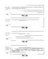
- FIG. 4A-4Hshow representations of the circular buffer of FIG. 1 while the surveillance apparatus is in use.
- an example surveillance apparatus 100generally comprising eyeglasses 110 having a camera 120 mounted at the nose bridge, and an optional viewfinder 130 applied onto one of the lenses.
- a data and power cord 140couples the camera 120 to a belt-worn recorder 160 , which cooperates with a ring-shaped signaling device 150 and a remote memory 170 .
- surveillanceis used herein in its broadest possible sense, to include not only professional or commercial types of surveillance, but also any other type of observation, including for example an ordinary person watching a baseball game or birthday party.
- the eyeglasses 110are used here euphemistically to represent any type of camera mount.
- the camera mountis disguised to be a common object worn by a person or lying around a house, but could also be shaped and sized to look like a camera.
- Contemplated mountsinclude lapel pins, hair clips, shirt buttons, purses, staplers, desk clocks, tripods, head gear, hand grips, or security camera mounts.
- the term “camera”means any device or collection of devices that includes an image capturing component that captures image data, and a converting component that converts the image data into digital data, possibly at least one data stream.
- An image capturing componentcould include one or more charge-couple devices (CCD) complimentary metal-oxide-semiconductors (CMOS), CMOS focal plane arrays (CFP), radiometers, or other manners of image obtaining devices.
- CCDcharge-couple devices
- CMOScomplimentary metal-oxide-semiconductors
- CFPCMOS focal plane arrays
- Radiometersor other manners of image obtaining devices.
- Camera 120should be interpreted euphemistically to include all such variants.
- a suitable converting componentcould include one or more analog-to-digital converters, software codecs, or integrated circuits.
- Camera 120contains an imager lens 122 used to focus images for camera 120 .
- Conventional lensesallow one or more of the following adjustments: aperture (to control the amount of light), zoom (to control the field-of-view), or shutter speed (to capture continuous motion).
- these adjustmentsare automatically controlled by the camcorder electronics, generally to maintain constant exposure onto the imager without the manual adjustment from a user. It is contemplated that the preferred embodiments offer direct user control of all major optical functions.
- an analog-to-digital (ADC) converteris used to digitize the analog imager waveform output into a discrete digital-video signal.
- ADCanalog-to-digital
- the recordercan be used to record analog or digital formats.
- Viewfinder image lens 130is calibrated to have the same field of view as camera 120 .
- viewfinder image lens 130is embedded in between the two glass lenses of eyeglasses 110 .
- viewfinder image lens 130is a zoom lens with preferred standard zoom ration of 3 ⁇ in or out of the focal length of the camera.
- a more sophisticated viewfinder image lens 130is contemplated to have a greater zoom range and also has nighttime vision or is able to render images under different light conditions.
- viewfinder image lens 130is outlined by tinted area or graticle and the outline graticle is embedded with glowing fiber optic filament.
- Eye-glassesare made preferably from opaque, translucent, or possibly photo gray-type tint of glasses. Alternatively, glasses change color slightly when energized.
- viewfinder image lens 130can be permanently fixed to camera 120 , or it can be interchangeable with lenses of different focal lengths and other properties depending on the need and circumstances of use.
- Recorder 160is any recording device that records video and/or audio/video data, including conventional recorders.
- Recorder 160preferably includes a processor 162 with software or hardware that accomplishes the functions described herein, or one or more physical memories that are collectively referred to herein as memory 166 .
- the recorder or the cameraconverts analog images into a digital format to be stored in the memory, or also preferably records both audio and video input analog signals from the camera to the memory.
- a wearercould clip recorder 160 as a belt clip or another compact device.
- Contemplated recordersinclude MP3 players, purses, or buttons. It is also contemplated that recorder 160 could also comprise a cell or mobile phone having a suitable recorder application installed that is configured to communicate with the other components of apparatus 100 .
- recorder 160also includes an appropriate power supply or connection, supporting electronics, or a display or other interface.
- the power sourcecan vary considerably.
- a suitable power sourcecan include a rechargeable battery.
- an appropriate power sourcecan include an external power source (e.g., transformer for wall outlet or cigarette lighter adapter).
- recordercan include some sort of security control requiring a password and some sort of automatic turnoff feature that activates after a certain amount of inactivity.
- Authentication or authorization of user accessprovides for ensuring a proper user of apparatus 100 retains desired control. For example, once a user is authenticated, the user can control indexing, editing, transmitting, or adjusting content data in memory.
- Recorder 160would typically record images in digital format, but analog or combination formats are also contemplated.
- the recorder's electronicsare preferably all on a unitary printed circuit board with different functions, or facilities, encoded on a programmable chip or disk.
- a recording facility 163could record the data stream from camera 120 to local memory 166
- a protecting facility 164could protect segments (not shown) of recorded data on memory 166
- a sending facility 165could transmit protected segments (not shown) of recorded data to remote memory 170 .
- the different facilitiesare preferably part of a single hardware or software program, the facilities could be split into different components as necessary.
- Other facilitiescould be installed, for example a facility that allows editing of the received image data or protected data. It is contemplated that such facilities could be purchased through or installed on a cell phone, possibly through an on-line application store.
- the contemplated memorycould vary depending on the particular configuration of the recorder.
- Particularly suitable memoriesinclude commercially available micro hard drives with a 1-inch disc (which can preferably have a capacity of more than 1 GB), flash memory cards with a capacity of up to 128 MB and more, or other transient and/or permanent memory units.
- suitable memorycan also include SDRAM, MRAM, racetrack memory, SIMM, DIMM, etc. with a capacity of at least 32 MB, more preferably at least 64 MB, or most preferably above 128 MB.
- memory 164is a SDRAM capable of storing at least 1000 frames of data. Once received by memory 164 , frames are preferably compressed by employing conventional compression rates and methods to achieve at least a 50:1 ratio.
- image data received by recorder 160is stored in a circular buffer 167 on memory 166 .
- all of the free space in memory 166is used to create circular buffer 167 , however, multiple circular buffers could be created in the memory where there exist multiple cameras connected to a single recorder.
- image datais continuously stored in circular buffer 167 for access. If no record or protect button is pushed, the recorder will loop back and store the image data for a said length of time. Recording, book-marking and protecting are used synonymously herein.
- Recording, book-marking and protectingmeans that a portion of the imaged data is write-protected upon an activation of a signal by a user and can not then be overwritten unless the write-protection is later removed. Consequently, protected data cannot be overwritten by newly stored imaged data in the circular buffer.
- the circular bufferis preferably large enough to store at least 3 minutes of data, more preferably 5 minutes and most preferred 10 minutes of data. However, it is contemplated that depending on the size and capacity of the device, any length longer or shorter is possible. It is preferred when the recorder is turned on the entire circular buffer is treated and stored as a single file. Thus, if no recording is protected or bookmarked, then the entire file will be erased and the recording will start at the beginning of the circular buffer.
- Signaling device 150is shown in the figure as a ring that communicates wirelessly (e.g., BlueTooth, Skinplex, wireless USB, 802.11, 802.15, UWB, Z-Wave, IrDa, Zigbee, etc.) with the recorder, possibly as part of a personal area network (PAN).
- the ringcan have any suitable interface, shown in FIGS. 2A and 2B , including for example buttons on its outer periphery, or a sensor along its inner edge.
- ring 150has user interface 200 , with a start signal button 210 , a stop signal button 220 , a transmit button 230 , a zoom in button 240 , or a zoom out button 250 .
- the buttonscould have decorative symbols in lieu of words of function as shown in FIG. 2B , or could even have arbitrary symbols surrounding the entirety of signaling device 150 . These buttons allow a user to manipulate and control image data and to generate protected data.
- turning the ring in one directionmight produce a start signal, and continuing to turn the ring in that direction might extend backwards the time period that is protected. Where a default time period for storing pre-start signal data is used, extending the time can be considered overriding the default.
- turning the ring in the opposite directionmight produce a stop signal, and where a default time period for storing post-start signal data is used, extending the time can be considered overriding that default.
- Electronics for such a ring or other control deviceare readily available, and for example are similar to those used in key fobs. Indeed, signaling device 150 should be interpreted euphemistically to include key fob type device.
- the signaling devicecould be integrated into other items as an accessory and that is wearable on an individual, for example a lapel pin or a pen within a pocked protector. It is also contemplated that the switch could be portable or can be hidden or attached to other devices such as a vehicle, furniture, etc.
- the signalcould also be generated in non-tactile ways, for example by an audio command or whistle, or by an automatic sensor. Preferably, the user could configure the audio signal to match only his/her voice.
- the usercan signal recorder 160 to place a “bookmark” in the recording.
- This signalcan be sent by pressing a button that will then transmit a signal through wires 140 that attach to the glasses then to the recorder.
- the wires 140could be fiber optic wires that are small and thin to avoid detection.
- the usercould control the entire system using signaling device 150 , for example by turning the camera on and off, recording a portion of image data, stop the recording, zooming in and out of image data; or transmitting protected data into the remote memory 170 .
- remote memory 170is shown in the figure as a mobile or cell phone, remote memory 170 should be interpreted euphemistically to include any memory that is not connected to surveillance apparatus 100 , for example, a DVD writer, a wireless network attached storage (NAS) device, a wireless storage area network (SAN) device, a home computer, or even a second surveillance apparatus.
- NASwireless network attached storage
- SANwireless storage area network
- sending facility 165sends protected segments of circular buffer 169 wirelessly to remote memory 170 whenever remote memory 170 is within range of wireless transceiver 169 , possibly as part of a PAN using one or more wireless communication technologies (e.g., BlueTooth, Skinplex, wireless USB, 802.11, 802.15, UWB, Z-Wave, IrDa, Zigbee, etc.).
- wireless communication technologiese.g., BlueTooth, Skinplex, wireless USB, 802.11, 802.15, UWB, Z-Wave, IrDa, Zigbee, etc.
- sending facility 165could also respond to manual commands, for example through a button on signaling device 150 , recorder 160 , or the mobile phone itself.
- the mobile phonedoes not act as a remote memory depository, and instead forwards the protected segment to a remote memory via a mobile internet or wi-fi connection.
- the protected memory areasthen will go back to become free memory areas that are available for further loop recording.
- Write-protected datacould be sent to the remote memory by an image sensor that outputs data directly in “block” format typically converted with a raster-to-block converter. Further compression could be used before transmitting the data if wireless bandwidth is an issue. Either DCT or wavelet transformed data on native sensor formats could be used.
- the datais preferably transmitted via the Internet, but could also be transmitted using radio waves, a pager, a two-way pager, a physical cable, email, text message, picture message, or any other suitable communication mechanism.
- FIG. 3shows a diagram representation of circular buffer 167 in memory 166 , with unprotected segment 320 and write-protected segment 330 .
- Write-protected segment 330is characterized as a predefined portion of the recording data.
- the recording facility 163continuously records the data stream 310 into circular buffer 167 .
- the recording facility 163records over unprotected segment 320 of circular buffer 167 , while skipping over protected segments 330 of circular buffer 167 . It is contemplated that the portion of the circular buffer that is marked as write-protected data cannot be overwritten once the recorder loops back to the beginning of the media.
- FIGS. 4A-4Hshow an alternative diagram representation of a circular buffer 300 as it is being used.
- FIG. 4Athe recording facility (not shown) records data stream “A” into circular buffer 400 .
- the “_” characteris used to designate blank memory, or unprotected memory that can be overwritten.
- the ellipsis “ . . . ”is used to show that the memory can be very large relative to the number of positions shown in the figure. It is contemplated, for example, that memory 400 can be up to several hundred megabytes, 1 GB, 2 GB, 4 GB, 8 GB, or even more.
- Such memoryis preferably of a flash type, non-volatile RAM, preferably in the form of a standard flash memory card.
- circular buffer 400comprises a logical representation of a physical memory area. Buffer 400 can be configured to store data in the physical memory by taking into account wear-leveling across the physical memory.
- the protecting facility(not shown) has protected a recent period of data stream “A” as a function of a start signal, shown by the character “
- the start signalcan be triggered in any suitable manner, including for example manual operation of a trigger or a switch by a user.
- the ring of FIG. 1could be used as a switch, or any other wearable accessory could have a switch integrated into it.
- start signalscan be triggered by detection of a particular circumstance by a motion, sound or other sensor.
- softwarecan operate upon content in the data stream, such as by monitoring an entrance to a building using a data stream received from one or more cameras, and could then send a start signal when the image shows a person loitering in a certain area of the screen.
- the “[” characteris used to designate the start of protected memory. Concomitantly, the portion of the data stream prior to the protected portion has once again been marked “_” to show that it is unprotected.
- the systemcan protect a default historical time period before the start signal is sent and protect a default period after the start signal is sent (such as 30 seconds, 2 minutes, etc). All suitable defaults are contemplated.
- the historical time period being protectedcould be altered in some manner, such as by software or by a user operating a history button. For example, if a user hits a start button, the system might default to protecting the last 30 seconds and the next 60 seconds; or it might protect the last 15 seconds and the next 2 minutes.
- the systemsends a signal to the user that the system is about to stop write-protecting data.
- the systemcould send an audio chirp signal, or in the case of a pair of eyeglasses, a portion of the glasses could slightly vibrate to signal that the system will stop recording in 10 seconds.
- the usercould hit a “more time” button. In this manner a user could protect a 5 or 10 minute period, or an even much longer portion of a data stream prior to a start signal.
- memory 400is interpreted as a multi gigabyte flash memory, it is entirely possible that one could back up sufficiently to protect an hour or more of such a data stream.
- the protecting facilityhas received a “stop” signal some time after receiving the start signal, thereby lengthening the protected portion of the “A” data stream.
- the stop signalis shown as character “]” and could be automatically generated from software or hardware as a function of a default time after the start signal, or could be manually sent by the user of the system. All suitable defaults are contemplated, including for example a 30 second or 1 minute time period. Stop signals could also be generated in a variable fashion, again as a function of software or hardware, through action of a user, or in any other suitable manner. Thus, a user can well operate a start button or other switch, a more time switch, and a stop switch, which could have the same or different interfaces. It is also contemplated that the system could recognize a user's verbal commands for these functions.
- contemplated systemscan utilize a default post-start signal period of time for which a portion of the data stream is stored unless overridden in some manner.
- Using defaults for both pre-start and post-start signal periodsallows a system to operate with an extremely high level of user convenience. For example, in one contemplated class of systems using such defaults, a user could operate a single button, ring or other interface to initiate a start signal, and the system could respond by automatically storing a default 60 second portion of a data stream prior to the signal, as well as a default 30 time period of the data stream after the signal.
- An interfacecould also be provided to allow the user to alter the length of time for the pre-recorded portion and the length of time for the post-recorded portion. As should be apparent from the description above, all reasonable the default time periods are contemplated.
- the systemhas finished protecting the desired portion of the “A” data stream, and the recording facility continues to store a “B” data stream into circular buffer 400 .
- the “B” data streamcan be contiguous with the “A” data stream, so that differentiation of “A” and “B” streams is merely an artifact of how the data is being stored. For example, if a system included an eyeglasses camera being used at baseball game, the wearer might watch the game for an hour or more without anything of interest happening. During all that time the system would record image frames from the camera, looping in memory if the memory had remaining capacity for less than an hour of images.
- the wearerWhen finally the wearer sees an interesting play that he wants to protect, he operates a start button, or perhaps a more time button to protect the previous minute of play. Once the interesting action has completed, he operates a stop button, which thereby causes the system to complete protecting the entire “A” period of interest. But the wearer continues watching the game, and the subsequent images, continuous with the “A” images, would be considered “B” images.
- the wearercan select to have more of previously recorded data to be protected. For example, once the wearer operates the start button, the wearer could also indicates that additional previously recorded data should be protected (e.g., past 10 seconds, 30 seconds, one minute, five minutes, etc.) while new image data is being stored and protected.
- FIG. 4Ethe system has again received a start signal, and has again protected a fixed or variable historical time period.
- FIG. 4Fthe system has received a stop signal, and has protected the entire desired portion of the “B” data stream.
- FIG. 4Gthe system has continued to record data, which is now depicted as data stream “C” because it follows data stream “B”. This figure is particularly significant in that recordation of the “C” data stream skips over the protected portion of the “A” data stream.
- FIG. 4Hthe system received another start signal, and has protected a desired portion of the “C” data stream that straddles the protected “A” stream. As shown, the C data stream is saved as a physically dis-contiguous file.
- segments of recorded dataare “write-protected” by being indexed in an electronic index.
- This schemeallows the system to protect previously recorded areas of memory without interrupting any concurrent recording, and further allows the system to easily locate such protected segments for play-back or offloading to a remote memory. Additionally, this allows the system to keep track of multiple fragments dis-contiguous fragments of a single write-protected segment.
- the electronic indexis preferably a hash table or a clustered index, but other methods of addressing memory are also suitable.
- Protected datacan be copied to a memory separate from the circular buffer, for example in a separate file within a local memory. Multiple segments of protected data could thus be stored as a series of protected files in a directory structure.
- the recordersearches for a remote memory in range, and immediately copies the protected data from the circular buffer to the remote memory. Once confirmation of copying is received, the index can be updated to identify the previously protected portion of the circular buffer as being non-protected.
- a sending facilityuses a wireless transmitter to transmit write-protected data to a remote memory.
- a surveillance apparatusparticipates in a PAN with other components including the remote memory.
- the apparatuscan discover other components of the system, including the remote memory or signaling devices, by sending message over one or more suitable protocols (e.g., BlueTooth, Skinplex, wireless USB, 802.11, 802.15, 802.16, UWB, Z-Wave, IrDA, Zigbee, etc.).
- suitable protocolse.g., BlueTooth, Skinplex, wireless USB, 802.11, 802.15, 802.16, UWB, Z-Wave, IrDA, Zigbee, etc.
- Component discoverycan be via a push where the apparatus sends a discovery message over a protocol to remote components or via a pull where the remote components send a discovery message to the apparatus.
- the components of the systemcan respond with a discovery response message.
- Preferred discovery or discovery response messagescomprise characteristics of the various responding components including buffer size, read/write rates, authentication, authorized command sets, or other parameters.
- the surveillance apparatuscould send a discovery message out to discover any suitable remote memories in the PAN where the message is encapsulated in a BlueTooth protocol packet.
- a cell phonecould respond by allocating a memory area to operate as a remote memory and by sending a discovery response message back to the apparatus describing the amount of memory available.
- Such an approachprovides for creating surveillance apparatus products that are able to operate across multiple cell phone platforms by allowing a cell phone user to download or install an application, or possibly a driver for their specific cell phone model, capable of being discovered and operating with the apparatus.
- Another aspect of transmitting data to the remote memoryincludes authenticating the various components with respect to access or to control remote memory.
- the surveillance apparatusor even the signaling facility, can be authenticated with the remote memory via a suitable token exchange (e.g., passwords, public-private key, handshakes, etc.).
- a remote memorycould be bound to a specific apparatus via a secret key, possibly having a UUID or GUID.
- the components of the systemcan be authorized to access various levels of functionality based on their authentication. Some apparatus could have read only access, while other could have write access, or while still others have editing capabilities.
- Yet another aspect of transmitting data to the remote memoryincludes the remote memory providing access to multiple surveillance apparatus.
- a single remote memorypossibly a cell phone, could be in close proximity (e.g., physically local within 100 meters or logically local within the same network) to two or more apparatus.
- the remote memorycan provide image storage as necessary to each apparatus, assuming appropriate authentication or permissions.
- a single apparatuscould have more than one camera where each camera has its data transmitted to the remote memory collectively via the apparatus or even individually, possibly where each camera has access to different remote memories, or different areas (e.g., files) in the same remote memory.
- a surveillance apparatuscan employ multiple wireless protocols to interact with the various components.
- the apparatus's signaling devicecould connect to a recorded via Zigbee or Skiplex protocols while the apparatus could connect to the remote memory via IEEE 802.16.
- One purpose of the inventionis to allow secret recording by a user.
- the usercan integrate the recorder as part of his/her wardrobe or even as clothing accessories, such as a pin or a hat.
- recorderwill record video and audio as seen from the wearer's point of view without requiring the wearer to exert any special effort to operate the recorder.
- the recorderoperates for extended periods of time while remaining unobtrusive both to the wearer/operator and to the subject(s) being recorded.
- the recorder portionmust be small and lightweight enough to be unobtrusive.
- the size of the recorderis two inches by three inches by one-half inch and six ounces in weight including battery.
- the camera or imaging componentmust be small and lightweight enough to be mounted on a pair of eyeglasses without conspicuous bulk or uncomfortable weight on the order of one-quarter inch by one-quarter inch by one inch or smaller and weighing one ounce or less.
- the imaging componentmust be capable of sufficient resolution that the image quality of the resulting recording is comparable with existing consumer camcorder products.
- Preferred resolutionsare at least 640 ⁇ 480 pixels. However, more preferred resolutions include high definition quality resolutions (e.g., 720p, 1080i, 1080p, 2160p, etc.).
- the recorder devicecan be mounted on vehicles, planes or any other objects for ease of use. It is contemplated that the present invention can be used in military or field intelligence operations.
- a user of the inventive subject mattercan capture image data while also participating with others in an event without being trapped behind a recording device. Furthermore, the user's hands can remain substantially free while recording.
- the terms “comprises” and “comprising”should be interpreted as referring to elements, components, or steps in a non-exclusive manner, indicating that the referenced elements, components, or steps can be present, or utilized, or combined with other elements, components, or steps that are not expressly referenced.
- the specification claimsrefers to at least one of something selected from the group consisting of A, B, C . . . and N, the text should be interpreted as requiring only one element from the group, not A plus N, or B plus N, etc.
Landscapes
- Engineering & Computer Science (AREA)
- Multimedia (AREA)
- Signal Processing (AREA)
- Computer Security & Cryptography (AREA)
- Television Signal Processing For Recording (AREA)
Abstract
Description
Claims (20)
Priority Applications (8)
| Application Number | Priority Date | Filing Date | Title |
|---|---|---|---|
| US12/268,286US7593034B2 (en) | 2006-08-31 | 2008-11-10 | Loop recording with book marking |
| US12/560,584US8692882B2 (en) | 2006-08-31 | 2009-09-16 | Loop recording with book marking |
| US13/790,553US9485471B2 (en) | 2006-08-31 | 2013-03-08 | Write-protected recording |
| US15/279,155US9912914B2 (en) | 2006-08-31 | 2016-09-28 | Write-protected recording |
| US15/875,828US10523901B2 (en) | 2006-08-31 | 2018-01-19 | Wearable recording system with memory designation |
| US16/724,829US10965910B2 (en) | 2006-08-31 | 2019-12-23 | Wearable recording system with memory designation |
| US17/210,319US11937017B2 (en) | 2006-08-31 | 2021-03-23 | Wearable recording system with memory designation |
| US18/202,594US20240195942A1 (en) | 2006-08-31 | 2023-05-26 | Wearable recording system with memory designation |
Applications Claiming Priority (5)
| Application Number | Priority Date | Filing Date | Title |
|---|---|---|---|
| US82409706P | 2006-08-31 | 2006-08-31 | |
| US82409506P | 2006-08-31 | 2006-08-31 | |
| US11/770,920US8310540B2 (en) | 2006-08-31 | 2007-06-29 | Loop recording with book marking |
| US11/846,217US8928752B2 (en) | 2006-08-31 | 2007-08-28 | Recording device with pre-start signal storage capability |
| US12/268,286US7593034B2 (en) | 2006-08-31 | 2008-11-10 | Loop recording with book marking |
Related Parent Applications (3)
| Application Number | Title | Priority Date | Filing Date |
|---|---|---|---|
| US11/770,920Continuation-In-PartUS8310540B2 (en) | 2006-08-31 | 2007-06-29 | Loop recording with book marking |
| US11/846,217Continuation-In-PartUS8928752B2 (en) | 2006-08-31 | 2007-08-28 | Recording device with pre-start signal storage capability |
| US13/790,553Continuation-In-PartUS9485471B2 (en) | 2006-08-31 | 2013-03-08 | Write-protected recording |
Related Child Applications (2)
| Application Number | Title | Priority Date | Filing Date |
|---|---|---|---|
| US12/560,584ContinuationUS8692882B2 (en) | 2006-08-31 | 2009-09-16 | Loop recording with book marking |
| US12/560,584Continuation-In-PartUS8692882B2 (en) | 2006-08-31 | 2009-09-16 | Loop recording with book marking |
Publications (2)
| Publication Number | Publication Date |
|---|---|
| US20090051768A1 US20090051768A1 (en) | 2009-02-26 |
| US7593034B2true US7593034B2 (en) | 2009-09-22 |
Family
ID=40381748
Family Applications (8)
| Application Number | Title | Priority Date | Filing Date |
|---|---|---|---|
| US12/268,286ActiveUS7593034B2 (en) | 2006-08-31 | 2008-11-10 | Loop recording with book marking |
| US12/560,584Active2030-11-19US8692882B2 (en) | 2006-08-31 | 2009-09-16 | Loop recording with book marking |
| US13/790,553Active2029-06-30US9485471B2 (en) | 2006-08-31 | 2013-03-08 | Write-protected recording |
| US15/279,155ActiveUS9912914B2 (en) | 2006-08-31 | 2016-09-28 | Write-protected recording |
| US15/875,828ActiveUS10523901B2 (en) | 2006-08-31 | 2018-01-19 | Wearable recording system with memory designation |
| US16/724,829ActiveUS10965910B2 (en) | 2006-08-31 | 2019-12-23 | Wearable recording system with memory designation |
| US17/210,319ActiveUS11937017B2 (en) | 2006-08-31 | 2021-03-23 | Wearable recording system with memory designation |
| US18/202,594PendingUS20240195942A1 (en) | 2006-08-31 | 2023-05-26 | Wearable recording system with memory designation |
Family Applications After (7)
| Application Number | Title | Priority Date | Filing Date |
|---|---|---|---|
| US12/560,584Active2030-11-19US8692882B2 (en) | 2006-08-31 | 2009-09-16 | Loop recording with book marking |
| US13/790,553Active2029-06-30US9485471B2 (en) | 2006-08-31 | 2013-03-08 | Write-protected recording |
| US15/279,155ActiveUS9912914B2 (en) | 2006-08-31 | 2016-09-28 | Write-protected recording |
| US15/875,828ActiveUS10523901B2 (en) | 2006-08-31 | 2018-01-19 | Wearable recording system with memory designation |
| US16/724,829ActiveUS10965910B2 (en) | 2006-08-31 | 2019-12-23 | Wearable recording system with memory designation |
| US17/210,319ActiveUS11937017B2 (en) | 2006-08-31 | 2021-03-23 | Wearable recording system with memory designation |
| US18/202,594PendingUS20240195942A1 (en) | 2006-08-31 | 2023-05-26 | Wearable recording system with memory designation |
Country Status (1)
| Country | Link |
|---|---|
| US (8) | US7593034B2 (en) |
Cited By (7)
| Publication number | Priority date | Publication date | Assignee | Title |
|---|---|---|---|---|
| US20080170130A1 (en)* | 2007-01-10 | 2008-07-17 | V.I.O. | Point-of-view integrated video system having tagging and loop mode features |
| US20090251533A1 (en)* | 2008-04-06 | 2009-10-08 | Smith Patrick W | Systems And Methods For Coordinating Collection Of Evidence |
| US20160224476A1 (en)* | 2012-02-08 | 2016-08-04 | Bendix Commercial Vehicle Systems Llc | Protect information stored in ecu from unintentional writing and overwriting |
| US10192277B2 (en) | 2015-07-14 | 2019-01-29 | Axon Enterprise, Inc. | Systems and methods for generating an audit trail for auditable devices |
| US10269384B2 (en) | 2008-04-06 | 2019-04-23 | Taser International, Inc. | Systems and methods for a recorder user interface |
| US10409621B2 (en) | 2014-10-20 | 2019-09-10 | Taser International, Inc. | Systems and methods for distributed control |
| US10965910B2 (en) | 2006-08-31 | 2021-03-30 | Stellar, Llc | Wearable recording system with memory designation |
Families Citing this family (34)
| Publication number | Priority date | Publication date | Assignee | Title |
|---|---|---|---|---|
| JP2009223929A (en)* | 2008-03-13 | 2009-10-01 | Sanyo Electric Co Ltd | Digital data reproducing device |
| US8296063B1 (en) | 2009-05-04 | 2012-10-23 | Exelis Inc. | Emergency rescue system and method having video and IMU data synchronization |
| US8565586B2 (en)* | 2009-05-20 | 2013-10-22 | Microsoft Corporation | Recorder vacation mode |
| CN102906763A (en)* | 2010-01-28 | 2013-01-30 | 美国路通创新科技公司 | Document Imaging System with Capture Scanner and PC-based Processing Software |
| GB201006913D0 (en)* | 2010-04-26 | 2010-06-09 | Taylor Richard | Refractive eyewear |
| US9787397B2 (en) | 2011-07-26 | 2017-10-10 | Abl Ip Holding Llc | Self identifying modulated light source |
| US8334898B1 (en) | 2011-07-26 | 2012-12-18 | ByteLight, Inc. | Method and system for configuring an imaging device for the reception of digital pulse recognition information |
| US9287976B2 (en) | 2011-07-26 | 2016-03-15 | Abl Ip Holding Llc | Independent beacon based light position system |
| US9723676B2 (en) | 2011-07-26 | 2017-08-01 | Abl Ip Holding Llc | Method and system for modifying a beacon light source for use in a light based positioning system |
| US9444547B2 (en) | 2011-07-26 | 2016-09-13 | Abl Ip Holding Llc | Self-identifying one-way authentication method using optical signals |
| US8416290B2 (en)* | 2011-07-26 | 2013-04-09 | ByteLight, Inc. | Method and system for digital pulse recognition demodulation |
| US10272848B2 (en) | 2012-09-28 | 2019-04-30 | Digital Ally, Inc. | Mobile video and imaging system |
| US9049371B2 (en) | 2013-01-17 | 2015-06-02 | Motorola Solutions, Inc. | Method and apparatus for operating a camera |
| US9705600B1 (en) | 2013-06-05 | 2017-07-11 | Abl Ip Holding Llc | Method and system for optical communication |
| US20150316979A1 (en)* | 2014-05-02 | 2015-11-05 | Wolfcom Enterprises | System and method for body-worn camera with re-connect feature |
| US20150346932A1 (en)* | 2014-06-03 | 2015-12-03 | Praveen Nuthulapati | Methods and systems for snapshotting events with mobile devices |
| TWI556664B (en)* | 2014-11-24 | 2016-11-01 | To achieve a wireless interaction between an electronic device and an initiator | |
| US10224038B2 (en)* | 2015-07-14 | 2019-03-05 | International Business Machines Corporation | Off-device fact-checking of statements made in a call |
| US10230835B2 (en)* | 2015-07-14 | 2019-03-12 | International Business Machines Corporation | In-call fact-checking |
| US20170090814A1 (en)* | 2015-09-25 | 2017-03-30 | Intel Corporation | Efficient storage and retrieval for wearable-device data |
| EP3179472B1 (en) | 2015-12-11 | 2020-03-18 | Sony Mobile Communications, Inc. | Method and device for recording and analyzing data from a microphone |
| GB2546247A (en)* | 2016-01-05 | 2017-07-19 | Oclu Ltd | Video recording system and method |
| US10178341B2 (en)* | 2016-03-01 | 2019-01-08 | DISH Technologies L.L.C. | Network-based event recording |
| CN105635318B (en) | 2016-03-02 | 2021-02-09 | 腾讯科技(深圳)有限公司 | Image acquisition method and system |
| KR20200073211A (en)* | 2017-10-19 | 2020-06-23 | 소니 주식회사 | Electronics |
| US20190141283A1 (en)* | 2017-11-06 | 2019-05-09 | Jacob Haas | System for video recording |
| WO2019110755A1 (en)* | 2017-12-06 | 2019-06-13 | Roader Media Bv | Apparatus, system and method for capture of buffered images |
| US10834357B2 (en) | 2018-03-05 | 2020-11-10 | Hindsight Technologies, Llc | Continuous video capture glasses |
| WO2020065414A1 (en)* | 2018-09-26 | 2020-04-02 | Jeetendra Kochar | Surveillance systems and devices therefor |
| US11698733B2 (en) | 2019-01-30 | 2023-07-11 | Practechal Solutions, Inc. | Method and system for data transmission |
| US11018215B2 (en)* | 2019-03-14 | 2021-05-25 | Taiwan Semiconductor Manufacturing Company, Ltd. | Package and manufacturing method thereof |
| US11849248B2 (en)* | 2020-05-28 | 2023-12-19 | Gopro, Inc. | Method and apparatus for pre-buffer media storage |
| USD1009972S1 (en) | 2021-12-28 | 2024-01-02 | Hindsight Technologies, Llc | Eyeglass lens frames |
| USD1009973S1 (en) | 2021-12-28 | 2024-01-02 | Hindsight Technologies, Llc | Eyeglass lens frames |
Citations (5)
| Publication number | Priority date | Publication date | Assignee | Title |
|---|---|---|---|---|
| US5523799A (en) | 1991-04-24 | 1996-06-04 | Canon Kabushika Kaisha | Image storing device including an inhibiting function |
| EP1064783A1 (en) | 1998-03-25 | 2001-01-03 | W. Stephen G. Mann | Wearable camera system with viewfinder means |
| US6351798B1 (en)* | 1998-06-15 | 2002-02-26 | Nec Corporation | Address resolution unit and address resolution method for a multiprocessor system |
| WO2006044476A2 (en) | 2004-10-12 | 2006-04-27 | Robert Vernon Vanman | Method of and system for mobile surveillance and event recording |
| US7195164B2 (en)* | 2003-01-03 | 2007-03-27 | Symbol Technologies, Inc. | Optical code reading device having more than one imaging engine |
Family Cites Families (57)
| Publication number | Priority date | Publication date | Assignee | Title |
|---|---|---|---|---|
| JPS56168281A (en)* | 1980-05-29 | 1981-12-24 | Sony Corp | Control method for electronic apparatus |
| DE3819863A1 (en)* | 1987-06-12 | 1989-01-05 | Matsushita Electric Industrial Co Ltd | REMOTE CONTROL DEVICE FOR ELECTRONIC DEVICES |
| WO1992022983A2 (en) | 1991-06-11 | 1992-12-23 | Browne H Lee | Large capacity, random access, multi-source recorder player |
| US5204909A (en) | 1991-09-12 | 1993-04-20 | Cowan John A | Audio processing system using delayed audio |
| US6850252B1 (en)* | 1999-10-05 | 2005-02-01 | Steven M. Hoffberg | Intelligent electronic appliance system and method |
| EP0550397A1 (en) | 1992-01-02 | 1993-07-07 | Wolfgang Kainz | Observation and surveillance device for vehicles or the likes |
| CH683665B5 (en) | 1992-05-27 | 1994-10-31 | Ebauchesfabrik Eta Ag | local calling receiver. |
| US5381526A (en) | 1992-09-11 | 1995-01-10 | Eastman Kodak Company | Method and apparatus for storing and retrieving generalized image data |
| US5465120A (en) | 1994-02-07 | 1995-11-07 | The Grass Valley Group, Inc. | Spiral buffer for non-linear editing |
| US5689442A (en) | 1995-03-22 | 1997-11-18 | Witness Systems, Inc. | Event surveillance system |
| US6138147A (en) | 1995-07-14 | 2000-10-24 | Oracle Corporation | Method and apparatus for implementing seamless playback of continuous media feeds |
| US5790427A (en) | 1995-08-28 | 1998-08-04 | Westinghouse Air Brake Company | Event history data acquisition |
| US5982418A (en) | 1996-04-22 | 1999-11-09 | Sensormatic Electronics Corporation | Distributed video data storage in video surveillance system |
| US5996023A (en) | 1996-10-31 | 1999-11-30 | Sensormatic Electronics Corporation | Efficient pre-alarm buffer management in intelligent video information management system |
| US7587323B2 (en) | 2001-12-14 | 2009-09-08 | At&T Intellectual Property I, L.P. | System and method for developing tailored content |
| US6370198B1 (en) | 1997-04-07 | 2002-04-09 | Kinya Washino | Wide-band multi-format audio/video production system with frame-rate conversion |
| JP3413344B2 (en) | 1997-05-16 | 2003-06-03 | シャープ株式会社 | Image processing apparatus and operation method thereof |
| US7088387B1 (en) | 1997-08-05 | 2006-08-08 | Mitsubishi Electric Research Laboratories, Inc. | Video recording device responsive to triggering event |
| US6163338A (en) | 1997-12-11 | 2000-12-19 | Johnson; Dan | Apparatus and method for recapture of realtime events |
| CA2310114A1 (en)* | 1998-02-02 | 1999-08-02 | Steve Mann | Wearable camera system with viewfinder means |
| US6389340B1 (en)* | 1998-02-09 | 2002-05-14 | Gary A. Rayner | Vehicle data recorder |
| JP2000069428A (en)* | 1998-08-21 | 2000-03-03 | Sony Corp | Digital camera system |
| US6895165B2 (en) | 1998-08-28 | 2005-05-17 | Soundstarts, Inc. | Apparatus for enabling perpetual recording and instant playback or storage of a time-specific portion of an audio or audio visual broadcast medium |
| US6617963B1 (en)* | 1999-02-26 | 2003-09-09 | Sri International | Event-recording devices with identification codes |
| US7263073B2 (en) | 1999-03-18 | 2007-08-28 | Statsignal Ipc, Llc | Systems and methods for enabling a mobile user to notify an automated monitoring system of an emergency situation |
| US6804638B2 (en)* | 1999-04-30 | 2004-10-12 | Recent Memory Incorporated | Device and method for selective recall and preservation of events prior to decision to record the events |
| US6714720B1 (en)* | 2000-03-06 | 2004-03-30 | Ati International Srl | Method and apparatus for storing multi-media data |
| US6831652B1 (en) | 2000-03-24 | 2004-12-14 | Ati International, Srl | Method and system for storing graphics data |
| JP4863540B2 (en) | 2000-07-31 | 2012-01-25 | ソニー株式会社 | Recording / playback apparatus and content management method |
| US7779097B2 (en)* | 2000-09-07 | 2010-08-17 | Sonic Solutions | Methods and systems for use in network management of content |
| US7747143B2 (en) | 2001-01-15 | 2010-06-29 | Fast Forward Video, Inc. | Digital video recorder |
| US6950600B2 (en) | 2001-04-23 | 2005-09-27 | Mitsubishi Electric Research Labs, Inc. | Exponential storage system and method |
| US7017162B2 (en)* | 2001-07-10 | 2006-03-21 | Microsoft Corporation | Application program interface for network software platform |
| US7546602B2 (en)* | 2001-07-10 | 2009-06-09 | Microsoft Corporation | Application program interface for network software platform |
| US7162607B2 (en) | 2001-08-31 | 2007-01-09 | Intel Corporation | Apparatus and method for a data storage device with a plurality of randomly located data |
| US20030081127A1 (en) | 2001-10-30 | 2003-05-01 | Kirmuss Charles Bruno | Mobile digital video recording with pre-event recording |
| WO2004017249A2 (en) | 2002-08-14 | 2004-02-26 | Deja View, Inc. | Recording device that stores buffered digital signals to memory flashcards |
| US20080177994A1 (en)* | 2003-01-12 | 2008-07-24 | Yaron Mayer | System and method for improving the efficiency, comfort, and/or reliability in Operating Systems, such as for example Windows |
| JP2004289766A (en) | 2003-03-20 | 2004-10-14 | For-A Co Ltd | High-speed imaging apparatus |
| US7319485B2 (en) | 2003-03-21 | 2008-01-15 | Hewlett-Packard Development Company, L.P. | Apparatus and method for recording data in a circular fashion |
| US7986339B2 (en) | 2003-06-12 | 2011-07-26 | Redflex Traffic Systems Pty Ltd | Automated traffic violation monitoring and reporting system with combined video and still-image data |
| EP1645131A2 (en) | 2003-06-16 | 2006-04-12 | Daniel Armand | Multimedia data recording apparatus |
| US20060077256A1 (en) | 2003-11-07 | 2006-04-13 | Silvemail William B | High resolution pre-event record |
| WO2005076852A2 (en)* | 2004-02-04 | 2005-08-25 | Perseus Wireless, Inc. | Method and system for providing information to remote clients |
| WO2005081494A1 (en) | 2004-02-19 | 2005-09-01 | Telefonaktiebolaget Lm Ericsson (Publ) | Method and arrangement for state memory management |
| US8966506B2 (en) | 2004-04-23 | 2015-02-24 | Hewlett-Packard Development Company, L.P. | Method and apparatus for managing related drivers associated with a virtual bus driver |
| US7348895B2 (en) | 2004-11-03 | 2008-03-25 | Lagassey Paul J | Advanced automobile accident detection, data recordation and reporting system |
| KR20060068632A (en)* | 2004-12-16 | 2006-06-21 | 주식회사 대우일렉트로닉스 | How to Manage Write Points in Digital Video Recorders |
| US8620608B2 (en)* | 2005-01-27 | 2013-12-31 | Electro Industries/Gauge Tech | Intelligent electronic device and method thereof |
| US7697827B2 (en)* | 2005-10-17 | 2010-04-13 | Konicek Jeffrey C | User-friendlier interfaces for a camera |
| US20070132773A1 (en) | 2005-12-08 | 2007-06-14 | Smartdrive Systems Inc | Multi-stage memory buffer and automatic transfers in vehicle event recording systems |
| US20070150138A1 (en)* | 2005-12-08 | 2007-06-28 | James Plante | Memory management in event recording systems |
| US20070217761A1 (en) | 2006-03-07 | 2007-09-20 | Coban Research And Technologies, Inc. | Method for video/audio recording using unrestricted pre-event/post-event buffering with multiple bit and frame rates buffer files |
| US8310540B2 (en) | 2006-08-31 | 2012-11-13 | Stellar, Llc | Loop recording with book marking |
| US8928752B2 (en) | 2006-08-31 | 2015-01-06 | Stellar Llc | Recording device with pre-start signal storage capability |
| US7593034B2 (en) | 2006-08-31 | 2009-09-22 | Dekeyser Paul | Loop recording with book marking |
| US20090049050A1 (en)* | 2007-08-15 | 2009-02-19 | Jeff Whitehead | File-based horizontal storage system |
- 2008
- 2008-11-10USUS12/268,286patent/US7593034B2/enactiveActive
- 2009
- 2009-09-16USUS12/560,584patent/US8692882B2/enactiveActive
- 2013
- 2013-03-08USUS13/790,553patent/US9485471B2/enactiveActive
- 2016
- 2016-09-28USUS15/279,155patent/US9912914B2/enactiveActive
- 2018
- 2018-01-19USUS15/875,828patent/US10523901B2/enactiveActive
- 2019
- 2019-12-23USUS16/724,829patent/US10965910B2/enactiveActive
- 2021
- 2021-03-23USUS17/210,319patent/US11937017B2/enactiveActive
- 2023
- 2023-05-26USUS18/202,594patent/US20240195942A1/enactivePending
Patent Citations (5)
| Publication number | Priority date | Publication date | Assignee | Title |
|---|---|---|---|---|
| US5523799A (en) | 1991-04-24 | 1996-06-04 | Canon Kabushika Kaisha | Image storing device including an inhibiting function |
| EP1064783A1 (en) | 1998-03-25 | 2001-01-03 | W. Stephen G. Mann | Wearable camera system with viewfinder means |
| US6351798B1 (en)* | 1998-06-15 | 2002-02-26 | Nec Corporation | Address resolution unit and address resolution method for a multiprocessor system |
| US7195164B2 (en)* | 2003-01-03 | 2007-03-27 | Symbol Technologies, Inc. | Optical code reading device having more than one imaging engine |
| WO2006044476A2 (en) | 2004-10-12 | 2006-04-27 | Robert Vernon Vanman | Method of and system for mobile surveillance and event recording |
Cited By (21)
| Publication number | Priority date | Publication date | Assignee | Title |
|---|---|---|---|---|
| US10965910B2 (en) | 2006-08-31 | 2021-03-30 | Stellar, Llc | Wearable recording system with memory designation |
| US11937017B2 (en) | 2006-08-31 | 2024-03-19 | Stellar, Llc | Wearable recording system with memory designation |
| US20080170130A1 (en)* | 2007-01-10 | 2008-07-17 | V.I.O. | Point-of-view integrated video system having tagging and loop mode features |
| US8964014B2 (en)* | 2007-01-10 | 2015-02-24 | V.I.O. Inc. | Point-of-view integrated video system having tagging and loop mode features |
| US20090251533A1 (en)* | 2008-04-06 | 2009-10-08 | Smith Patrick W | Systems And Methods For Coordinating Collection Of Evidence |
| US11386929B2 (en) | 2008-04-06 | 2022-07-12 | Axon Enterprise, Inc. | Systems and methods for incident recording |
| US12431167B2 (en) | 2008-04-06 | 2025-09-30 | Axon Enterprise, Inc. | Incident recording systems and methods |
| US10269384B2 (en) | 2008-04-06 | 2019-04-23 | Taser International, Inc. | Systems and methods for a recorder user interface |
| US10354689B2 (en) | 2008-04-06 | 2019-07-16 | Taser International, Inc. | Systems and methods for event recorder logging |
| US10446183B2 (en) | 2008-04-06 | 2019-10-15 | Taser International, Inc. | Systems and methods for a recorder user interface |
| US11854578B2 (en) | 2008-04-06 | 2023-12-26 | Axon Enterprise, Inc. | Shift hub dock for incident recording systems and methods |
| US10872636B2 (en) | 2008-04-06 | 2020-12-22 | Axon Enterprise, Inc. | Systems and methods for incident recording |
| US20160224476A1 (en)* | 2012-02-08 | 2016-08-04 | Bendix Commercial Vehicle Systems Llc | Protect information stored in ecu from unintentional writing and overwriting |
| US10275366B2 (en)* | 2012-02-08 | 2019-04-30 | Bendix Commercial Vehicle Systems Llc | Protect information stored in ECU from unintentional writing and overwriting |
| US11544078B2 (en) | 2014-10-20 | 2023-01-03 | Axon Enterprise, Inc. | Systems and methods for distributed control |
| US10901754B2 (en) | 2014-10-20 | 2021-01-26 | Axon Enterprise, Inc. | Systems and methods for distributed control |
| US11900130B2 (en) | 2014-10-20 | 2024-02-13 | Axon Enterprise, Inc. | Systems and methods for distributed control |
| US10409621B2 (en) | 2014-10-20 | 2019-09-10 | Taser International, Inc. | Systems and methods for distributed control |
| US12386634B2 (en) | 2014-10-20 | 2025-08-12 | Axon Enterprise, Inc. | Systems and methods for distributed control |
| US10848717B2 (en) | 2015-07-14 | 2020-11-24 | Axon Enterprise, Inc. | Systems and methods for generating an audit trail for auditable devices |
| US10192277B2 (en) | 2015-07-14 | 2019-01-29 | Axon Enterprise, Inc. | Systems and methods for generating an audit trail for auditable devices |
Also Published As
| Publication number | Publication date |
|---|---|
| US20180146163A1 (en) | 2018-05-24 |
| US20090051768A1 (en) | 2009-02-26 |
| US20200128213A1 (en) | 2020-04-23 |
| US20100066830A1 (en) | 2010-03-18 |
| US20170019640A1 (en) | 2017-01-19 |
| US20240195942A1 (en) | 2024-06-13 |
| US9912914B2 (en) | 2018-03-06 |
| US20210211611A1 (en) | 2021-07-08 |
| US11937017B2 (en) | 2024-03-19 |
| US9485471B2 (en) | 2016-11-01 |
| US20130188048A1 (en) | 2013-07-25 |
| US10523901B2 (en) | 2019-12-31 |
| US10965910B2 (en) | 2021-03-30 |
| US8692882B2 (en) | 2014-04-08 |
Similar Documents
| Publication | Publication Date | Title |
|---|---|---|
| US11937017B2 (en) | Wearable recording system with memory designation | |
| US8310540B2 (en) | Loop recording with book marking | |
| US20170301370A1 (en) | Recorder with retrospective capture | |
| US10757378B2 (en) | Dual lens camera unit | |
| US8928752B2 (en) | Recording device with pre-start signal storage capability | |
| JP5023663B2 (en) | Imaging apparatus and imaging method | |
| US20040150717A1 (en) | Digital in-car video surveillance system | |
| US20060133476A1 (en) | Digital in-car video surveillance system | |
| US20040109059A1 (en) | Hybrid joint photographer's experts group (JPEG) /moving picture experts group (MPEG) specialized security video camera | |
| US20140160250A1 (en) | Head mountable camera system | |
| JP2008124885A (en) | Imaging system, and imaging method | |
| CN105190716A (en) | Camera Non-Touch Switch | |
| US20150281568A1 (en) | Content acquisition device, portable device, server, information processing device, and storage medium | |
| WO2009142357A1 (en) | System and method for transmitting video of entire law enforcement processing | |
| US8169493B2 (en) | Image acquisition system and method of authenticating image acquisition device in the image acquisition system | |
| CN108833832B (en) | A kind of glasses video recorder and video recording method | |
| CN109547722B (en) | Law enforcement recording method, storage medium, control device and law enforcement recorder | |
| JP2009055080A (en) | Imaging apparatus, and imaging method | |
| KR200254498Y1 (en) | Personal digital assistant connected with digital camcorder | |
| JP5979984B2 (en) | Imaging apparatus, control method thereof, and program | |
| KR100609421B1 (en) | Video camera system | |
| EP0933666A1 (en) | Image detecting apparatus controlled by detecting the viewing direction | |
| CN1979323A (en) | Digital-code camera whose view-finding lens is separated with cemera body | |
| JP2007334938A (en) | Information recording apparatus and information recording method | |
| WO2007123411A2 (en) | Film set system and processing unit incorporated therein |
Legal Events
| Date | Code | Title | Description |
|---|---|---|---|
| STCF | Information on status: patent grant | Free format text:PATENTED CASE | |
| FEPP | Fee payment procedure | Free format text:PAYOR NUMBER ASSIGNED (ORIGINAL EVENT CODE: ASPN); ENTITY STATUS OF PATENT OWNER: SMALL ENTITY | |
| AS | Assignment | Owner name:STELLAR, LLC, CALIFORNIA Free format text:ASSIGNMENT OF ASSIGNORS INTEREST;ASSIGNOR:DEKEYSER, PAUL;REEL/FRAME:028980/0430 Effective date:20120914 | |
| FPAY | Fee payment | Year of fee payment:4 | |
| CC | Certificate of correction | ||
| REMI | Maintenance fee reminder mailed | ||
| FEPP | Fee payment procedure | Free format text:7.5 YR SURCHARGE - LATE PMT W/IN 6 MO, SMALL ENTITY (ORIGINAL EVENT CODE: M2555) | |
| MAFP | Maintenance fee payment | Free format text:PAYMENT OF MAINTENANCE FEE, 8TH YR, SMALL ENTITY (ORIGINAL EVENT CODE: M2552) Year of fee payment:8 | |
| MAFP | Maintenance fee payment | Free format text:PAYMENT OF MAINTENANCE FEE, 12TH YR, SMALL ENTITY (ORIGINAL EVENT CODE: M2553); ENTITY STATUS OF PATENT OWNER: SMALL ENTITY Year of fee payment:12 | |
| IPR | Aia trial proceeding filed before the patent and appeal board: inter partes review | Free format text:TRIAL NO: IPR2024-01205 Opponent name:MOTOROLA SOLUTIONS, INC., AND WATCHGUARD VIDEO, INC. Effective date:20240722 | |
| AS | Assignment | Owner name:IP LITFIN US 2024 LLC, NEW YORK Free format text:PATENT SECURITY AGREEMENT;ASSIGNOR:STELLAR, LLC;REEL/FRAME:069230/0603 Effective date:20241008 |