US7593031B2 - Integrated desktop videoconferencing system - Google Patents
Integrated desktop videoconferencing systemDownload PDFInfo
- Publication number
- US7593031B2 US7593031B2US11/108,015US10801505AUS7593031B2US 7593031 B2US7593031 B2US 7593031B2US 10801505 AUS10801505 AUS 10801505AUS 7593031 B2US7593031 B2US 7593031B2
- Authority
- US
- United States
- Prior art keywords
- videoconferencing
- display
- electronics
- module
- flat panel
- Prior art date
- Legal status (The legal status is an assumption and is not a legal conclusion. Google has not performed a legal analysis and makes no representation as to the accuracy of the status listed.)
- Active, expires
Links
- 239000000463materialSubstances0.000claimsdescription4
- 230000008878couplingEffects0.000claims2
- 238000010168coupling processMethods0.000claims2
- 238000005859coupling reactionMethods0.000claims2
- 230000010354integrationEffects0.000abstractdescription4
- 230000009977dual effectEffects0.000abstractdescription2
- 230000006870functionEffects0.000description23
- 238000010276constructionMethods0.000description3
- 230000008901benefitEffects0.000description2
- 239000002131composite materialSubstances0.000description2
- 238000005516engineering processMethods0.000description2
- 238000012986modificationMethods0.000description2
- 230000004048modificationEffects0.000description2
- 230000005236sound signalEffects0.000description2
- 239000000853adhesiveSubstances0.000description1
- 230000001070adhesive effectEffects0.000description1
- 230000003321amplificationEffects0.000description1
- 230000000712assemblyEffects0.000description1
- 238000000429assemblyMethods0.000description1
- 238000006243chemical reactionMethods0.000description1
- 239000003086colorantSubstances0.000description1
- 238000004891communicationMethods0.000description1
- 238000013461designMethods0.000description1
- 238000011161developmentMethods0.000description1
- 238000000034methodMethods0.000description1
- 238000003199nucleic acid amplification methodMethods0.000description1
- 230000003287optical effectEffects0.000description1
- 238000012545processingMethods0.000description1
- -1shapesSubstances0.000description1
Images


Classifications
- H—ELECTRICITY
- H04—ELECTRIC COMMUNICATION TECHNIQUE
- H04N—PICTORIAL COMMUNICATION, e.g. TELEVISION
- H04N7/00—Television systems
- H04N7/14—Systems for two-way working
- H04N7/141—Systems for two-way working between two video terminals, e.g. videophone
- H04N7/142—Constructional details of the terminal equipment, e.g. arrangements of the camera and the display
- H—ELECTRICITY
- H04—ELECTRIC COMMUNICATION TECHNIQUE
- H04R—LOUDSPEAKERS, MICROPHONES, GRAMOPHONE PICK-UPS OR LIKE ACOUSTIC ELECTROMECHANICAL TRANSDUCERS; DEAF-AID SETS; PUBLIC ADDRESS SYSTEMS
- H04R5/00—Stereophonic arrangements
- H04R5/02—Spatial or constructional arrangements of loudspeakers
Definitions
- the present inventionrelates generally to a videoconferencing system, and more particularly to a videoconferencing system integrated into a computer display.
- Videoconferencing systemsPrior to around 1988, videoconferencing systems were too large to build into a cart. Videoconferencing systems were designed into custom rooms for, with the equipment placed in equipment closets, or otherwise concealed in custom furniture (shelves, etc). For example, the original PictureTel product (the C2000) weighed in excess of 250 pounds. This was only the codec, it did not include audio amplification/echo cancellation, video switching equipment, or the network interfaces needed to connect to the WAN.
- the Swiftsite(again PictureTel) was the first set-top unit.
- the electronics module and the camerawere integrated into a unit small enough to place on top of the monitor, thereby eliminating the need for a cart at all.
- Swiftsiteweighed in at 10 lbs.
- Today, even this form factoris becoming large and unwieldy compared to advances in flat panel displays and computer monitors. Additionally, the need for videoconferencing equipment has moved from custom designed and built conference rooms to individual offices. Therefore, what is needed is an even smaller videoconferencing form factor that better integrates with its surroundings in a modern office.
- the integrationprovides an improved form factor for the videoconferencing system.
- the integrationoffers the dual use as a computer monitor and as a videoconferencing system.
- the systemincludes a videoconferencing module attaching to a back of the flat panel display.
- the videoconferencing modulehas videoconferencing electronics that electronically connect to integral electronics of the display.
- the systemalso includes a microphone/camera module attaching to a top of the flat panel display.
- the microphone/camera modulehas a camera and microphone that both electronically connect to the videoconferencing electronics.
- FIG. 1schematically illustrates an integrated desktop videoconferencing system in accordance with certain teachings of the present disclosure.
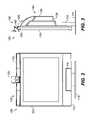
- FIG. 2illustrates a face-on view of an embodiment of an integrated desktop videoconferencing system in accordance with certain teachings of the present disclosure.
- FIG. 3illustrates a side view of the videoconferencing system of FIG. 2 .
- FIG. 4illustrates a rear view of the videoconferencing system of FIG. 2 .
- FIG. 5illustrates a top view of the videoconferencing system of FIG. 2 .
- FIGS. 6A-6Cillustrate detailed views of a microphone/camera module of the videoconferencing system of FIG. 2 .
- FIGS. 7A-7Billustrate exploded rear views of the videoconferencing system of FIG. 2 .
- the videoconferencing system 50includes a display 51 , display and audio electronics 52 , one or more speakers 53 , videoconferencing electronics 60 , a camera 62 , and one or more microphones 64 .
- the display 51is preferably a flat panel, LCD-type personal computer monitor.
- the display and audio electronics 52are integral to the display 51 and can be similar to those found in a PC type monitor.
- the videoconferencing electronics 60are mounted on the system 50 for conducting videoconferencing. Electronics for videoconferencing are known in the art so that details are not described herein.
- the videoconferencing unit 60has a network connection 61 for connecting to a network for videoconferencing. Details of such network connections for videoconferencing are known in the art and are not described herein.
- the videoconferencing electronics 60are connected to the integral electronics 52 of the display 51 so that the display 51 can show images of a video conference and the speakers 53 can produce the audio of the conference.
- the camera 62is mounted on the system 50 for obtaining images of a user and is electronically connected to the videoconferencing electronics 60 .
- the camera 62can be stationary, but the camera 62 is preferably capable of pan, tilt, and/or zoom operation. Accordingly, the camera 62 can have either a manual pan/tilt/zoom mechanism or alternatively electrically driven pan/tilt/zoom mechanism. Subsets of these operations, such as pan and tilt only may also be provided. As still another alternative, electronic pan and tilt may be provided for the camera 62 as described in co-pending and co-owned U.S. patent application Ser. Nos. 09/141,057 and 10/425,535, which are hereby incorporated by reference in their entireties.
- the microphone 64is mounted on the system 50 for obtaining audio for the video conference and is electronically connected to the videoconferencing unit 60 .
- the microphones 64are directed toward the front of the display 51 to obtain audio from the user at the display 51 .
- the display 51includes function buttons 54 for controlling various functions of both the display 51 and other portions of the videoconferencing system 50 .
- functions controlled by the function buttons 54are: a display mode (source switch) function, a display setup function, a speaker volume function, and a power switching (on/off) function.
- the button 54 for the display mode functionallows the user to select the operation of the system between a computer monitor mode and a videoconferencing mode.
- the button 54 for the display setup functionallows the user to enter a menu driven system of the display 51 in which various parameters of the display 51 and/or other portions of the videoconferencing system 50 may be manipulated.
- the button 54 for the power switching functionpreferably provides independent power switching to allow the computer display 51 to be used independently of other portions of the videoconferencing system 50 .
- the videoconferencing system 50 described hereincan be used additionally as a personal computer monitor.
- the display 51includes a video input 55 (e.g., VGA input) for receiving the video signal from a personal computer.
- the integrated desktop videoconferencing system 50also preferably includes a video output (e.g., VGA output) (not shown), which allows the connection of an additional monitor or display (not shown).
- This additional displaymay be used for use in a multiple-display videoconferencing mode, for example, a mode in which one monitor displays the participants at a remote location and the other monitor displays documents, such as a computer-based presentation.
- Multi-monitor videoconferencing systemsare known to those skilled in the art, and therefore details of such systems are not reproduced here.
- a video source pass-throughmay be included with the electronics 52 of the display 51 so that the image displayed on the display 51 may be shown on an additional display. Additional combinations of display modes are possible and would be apparent to one skilled in the art having the benefit of this disclosure.
- the display 51in accordance with other video signal standards, and thus the videoconferencing system 50 may include other forms of video signal inputs, such as an S-Video input, a composite video input, a DVI input, and/or a component video input. Any and all of these and a variety of other video formats are adaptable for use with the system 50 .
- the audio components of the integrated desktop videoconferencing system 50may be used to provide PC audio functionality. Obviously, this necessitates some form of audio input (not shown), various forms of which are known to those skilled in the art. Additionally, it is preferable to provide a headset plug (not shown) on the front bezel of display 51 , so that a user may use the audio functions of the videoconferencing system 50 and/or personal computer without disturbing others in the vicinity and/or with improved privacy.
- the display 51also preferably includes an integrated infrared detector 56 and associated electronics in the integral electronics 52 of the display.
- the display 51is an LCD computer monitor that also functions as an LCD television in which a remote control is practically a standard feature.
- the infrared detector 56allows an infrared remote control to control various features of the display 51 and/or the videoconferencing system 50 .
- the videoconferencing system 50 described hereinmay also be used in conjunction with displays lacking an infrared detector, or this functionality may be provided on the system 50 by separately integrating infrared receiver electronics with the videoconferencing electronics 60 , for example.
- the base of the display 51may include a dialing pad 57 to facilitate the placement of video and/or audio calls with the system 50 .
- the videoconferencing system 50may include a telephone jack 70 for connection of a standard telephone extension or a Voice over Internet Protocol (VoIP) telephone, which would then connect to the network for videoconferencing.
- the videoconferencing unit 60may include a wireless network interface, such as would comply with one or more of the IEEE 802.11a/b/g standards. Such a module would allow the integrated desktop videoconferencing system 50 to be used in varying locations and/or by a mobile user.
- the videoconferencing system 100includes a display 110 , a videoconferencing module 120 , and a microphone/camera module 130 .
- the display 110is preferably a flat panel type personal computer monitor, such as an LCD or plasma display.
- the videoconferencing module 120 and the microphone/camera module 130are mounted on the display 110 to form an integrated assembly with the display 110 .
- the videoconferencing module 120mounts to the back of display 110 .
- differences or changes in the typical, standard, or available sizes and/or form factors of either the display 110 or the videoconferencing module 120could result in a situation in which it would be more preferable to attach the videoconferencing module 120 in an alternate position.
- differences or changes in the typical, standard, or available sizes and/or form factors of the equipmentcould present a case in which it would be preferable to attach the microphone/camera module 130 in a different position.
- the display 110is preferably a standard flat panel display.
- the display 110has integral electronics (not shown) within its housing for operating the display 110 .
- Such integral electronicsare known in the art and not described herein.
- various additional featuresare preferred for the display 110 , and the inventors have found that LCD monitors produced by Sampo Corporation are particularly well suited for use in accordance with the integrated desktop videoconferencing system 100 described herein.
- a suitable Sampo monitoris the 17′′ LCD display having model number LME-17S3.
- Various featuresare integrated with the Sampo monitors, some of which are particularly advantageous in constructing the videoconferencing system 100 described herein.
- An example of such a featureis an amplified stereo sound system, including an audio amplifier (not shown) and speakers 112 in the Sampo monitor.
- Speakers 112may be positioned in various positions on the display 110 , and the speaker grilles are preferably integrated with the display bezel in such a way as to provide a functional, yet attractive system. Additional physical features that are advantageously part of the display 110 are a tilt or tilt/swivel base 114 and an integrated carrying handle 118 (illustrated most clearly in FIG. 6C ).
- the display 110preferably includes function buttons (not shown) for controlling various functions of both the display and videoconferencing system.
- the function buttonsare preferably located on the front bezel of the display 110 and may be provided with a cover 116 so that they are covered when not in use.
- the functions controlled by the function buttonsare: the display mode (source switch) function, the display setup function, the speaker volume function, and the power switching (on/off) function, described previously with reference to FIG. 1 .
- the display 110can include a VGA input, a VGA output, a VGA source pass-through, an S-Video input, a composite video input, a DVI input, a component video input, and additional features described previously with reference to FIG. 1 .
- the videoconferencing module 120is mounted on the display 110 . As best shown in FIG. 4 , the videoconferencing module 120 is attached to the back of the display 110 .
- the videoconferencing module 120includes an enclosure 122 having a main portion 124 and an intermediate portion 126 .
- the main enclosure portion 124houses videoconferencing electronics and other components (shown in detail in FIGS. 7A-7B ).
- the intermediate enclosure portion 126extends from the main portion 124 to the microphone/camera module 130 mounted on top of the display 110 . An end of the intermediate portion 126 abuts the microphone/camera module 130 , and the intermediate portion 126 hides various connections between electronics of the modules 120 and 130 .
- the main and intermediate portions 124 and 126are integrally connected together.
- the portions 124 and 126are separate and attached together by fasteners or the like.
- the intermediate portion 126is preferably formed to allow access to an integrated handle 118 (illustrated most clearly in FIG. 6C ) of the display 110 .
- the videoconferencing module 120is designed to be similar in color, materials, and general shape of the display 110 such that the integrated videoconferencing system 100 appears to be a single design. Additionally and as best shown in FIGS. 3-5 , the enclosure 122 for the videoconferencing module 120 is preferably designed to be clean looking and to provide an integrated appearance with the display 110 because, as a desktop system, individuals may be sitting behind the display 110 . As shown in FIG. 4 , the vent pattern on the main enclosure portion 124 is preferably designed to maximize vertical convection so that the vertical convection along with the vertical mounting allows the system 100 to run without a fan.
- the microphone/camera module 130is illustrated in perspective, face-on, and exploded rear view, respectively. As best shown in FIGS. 6A-6B , the microphone/camera module 130 is designed to fit along the top edge of the flat panel display 110 .
- the microphone/camera module 130can be attached to the display 110 using various techniques, such as fasteners, clamps, tape, adhesive, etc.
- the microphone/camera module 130includes a microphone unit 140 and a camera unit 150 .
- the microphone unit 140includes a body that houses microphones 142 for the audio portion of a videoconference.
- the camera unit 150which is necessary for the video portion of the videoconference, is centrally positioned on the body of the microphone unit 140 so that the microphones 142 are positioned on either side of the camera unit 150 .
- the module 130integrates the location of the microphones 142 with the camera unit 150 .
- the modularized construction of the videoconferencing module 120 and the microphone/camera module 130enables construction of the integrated desktop videoconferencing system 100 using standard personal computer (PC) type displays, such as the preferred Sampo monitor of the present embodiment. This reduces the development time and cost necessary to produce such a system, which ultimately reduces the cost of the system to the end user.
- PCpersonal computer
- the integrated desktop videoconferencing system 100may perform double duty as a personal computer monitor, as described previously.
- the microphone/camera module 130is preferably designed cosmetically to match the materials, shapes, colors, etc. of the display 110 to provide an integrated appearance.
- grills 143 shown in FIG. 6Bcover the microphones 142 housed in the microphone unit 140 .
- These grills 143are preferably vertically aligned with the grill of the speakers ( 112 ; FIG. 2 ) on the display 110 .
- the camera unit 150includes a body 152 , which houses an electronic camera (not shown) and has an opening for a lens 160 of the camera to capture images for videoconferencing.
- the camera unit 150has a manual pan/tilt mechanism 154 that attaches the body 152 to the microphone unit 140 .
- the manual pan/tilt mechanism 154is attached to a central location 155 of the microphone unit 140 with a fastener and washers, and the mechanism 154 allows the camera body 152 to pan and tilt.
- the camera body 152is allowed to pan and tilt about +/ ⁇ 20-degrees.
- the camera unit 150can have an electrically driven pan and tilt mechanism or can have electronic pan and tilt capabilities, such as described previously. Additionally, manual electric or electronic zoom capabilities may also be provided.
- a connector 165connects the camera unit 150 to other electronics (not shown) of the system.
- the camera unit 150also preferably incorporates a privacy shutter 158 , which may be manually or electrically actuated to conceal or expose the lens 160 .
- An infrared detector 162is also housed in the camera unit 150 and is preferably visible whether the shutter 158 is open or closed. This infrared detector 162 when used with a remote control can be used to control various functions of the display 110 and/or videoconferencing system.
- a manual focus wheel 156 on the camera unit 150allows the user to focus the camera without needing to touch the lens 160 when the camera unit 150 is in operation. Alternatively, electric manual focusing or automated focusing may also be provided.
- the camera unit 150can also support an electronic zoom capability, although cameras with normal optical zoom capabilities may also be included.
- each microphone 142is preferably a cardioid microphone angled at about 20-degrees towards the central location 155 of the module 130 to maximize the stereo pickup of the system 100 .
- the cavity for the microphones 142 and the placement of the microphones 142are shaped to maximize the pickup of the cardioid microphones 142 on each side.
- an electronic unit 144 coupled to the microphones 142is attached to the back of the central location 155 of the unit 140 .
- This electronic unit 144is used for processing audio signals and is coupled to other electronics (not shown) of the videoconferencing system.
- This electronic unit 144is covered by the end of the intermediate enclosure portion ( 126 ; FIG. 4 ) so that it is not visible when the system is assembled.
- the vertically orientated videoconferencing module 120is preferably attached to the display 110 via the standard mounting hole pattern 224 according to the Video Electronics Standards Association (VESA) on the back of the display 110 .
- VESAVideo Electronics Standards Association
- This arrangementhas numerous advantages, such as allowing for conversion of a standard computer monitor type display with minimal custom tooling and allowing for wall mounting of the integrated videoconferencing system 100 using standard brackets, including various tilt/swivel arrangements.
- the videoconferencing module 120includes an electronics module 200 and an electronics tray 220 .
- the electronics module 200contains all the necessary electronics for a videoconferencing system, including processors, memory, communication interfaces (LAN/WAN/ISDN), etc. Construction and implementation of such electronics for videoconferencing systems are known to those skilled in the art, thus the details are not reproduced here.
- the electronics tray 220mounts to the back of the display 110 with fasteners 222 connecting to the VESA mounting holes 224 of the display 110 . At least two of the fasteners 222 allow for adjustment of the tray 220 .
- the electronics module 200mounts in the tray 200 with fasteners (not shown).
- a connector 210has multiple connection members on one end 212 , which connect to inputs 214 on the display 110 .
- a cover 215may be used to hide the connector end 212 .
- the connector 210also has connectors on another end 216 , which connects to outputs 218 on the electronics module 200 so that video and audio signals can be transmitted from the electronics module 200 to the display 110 .
- the camera unit 150connects to the electronics module 200 with connector 164 and cable 165
- the microphone electronic unit 144connects to the module 200 with a cable 250
- the videoconferencing module 120also includes a cage member 230 , heat sinks 240 , and the enclosure 122 .
- the heat sinks 240mount to the electronics module 200
- the cage member 230attaches to the electronics tray 220 to protect the module 200 .
- the enclosure 122attaches with fasteners to the electronics tray 220 to complete the assembly.
Landscapes
- Engineering & Computer Science (AREA)
- Signal Processing (AREA)
- Physics & Mathematics (AREA)
- Acoustics & Sound (AREA)
- Multimedia (AREA)
- Two-Way Televisions, Distribution Of Moving Picture Or The Like (AREA)
- Studio Devices (AREA)
Abstract
Description
Claims (24)
Priority Applications (2)
| Application Number | Priority Date | Filing Date | Title |
|---|---|---|---|
| US11/108,015US7593031B2 (en) | 2004-04-16 | 2005-04-15 | Integrated desktop videoconferencing system |
| US12/418,299US20090189973A1 (en) | 2004-04-16 | 2009-04-03 | Integrated desktop videoconferencing system |
Applications Claiming Priority (2)
| Application Number | Priority Date | Filing Date | Title |
|---|---|---|---|
| US56318104P | 2004-04-16 | 2004-04-16 | |
| US11/108,015US7593031B2 (en) | 2004-04-16 | 2005-04-15 | Integrated desktop videoconferencing system |
Publications (2)
| Publication Number | Publication Date |
|---|---|
| US20050231587A1 US20050231587A1 (en) | 2005-10-20 |
| US7593031B2true US7593031B2 (en) | 2009-09-22 |
Family
ID=35095865
Family Applications (2)
| Application Number | Title | Priority Date | Filing Date |
|---|---|---|---|
| US11/108,015Active2028-06-23US7593031B2 (en) | 2004-04-16 | 2005-04-15 | Integrated desktop videoconferencing system |
| US12/418,299AbandonedUS20090189973A1 (en) | 2004-04-16 | 2009-04-03 | Integrated desktop videoconferencing system |
Family Applications After (1)
| Application Number | Title | Priority Date | Filing Date |
|---|---|---|---|
| US12/418,299AbandonedUS20090189973A1 (en) | 2004-04-16 | 2009-04-03 | Integrated desktop videoconferencing system |
Country Status (1)
| Country | Link |
|---|---|
| US (2) | US7593031B2 (en) |
Cited By (14)
| Publication number | Priority date | Publication date | Assignee | Title |
|---|---|---|---|---|
| US20100073455A1 (en)* | 2008-09-25 | 2010-03-25 | Hitachi, Ltd. | Television receiver with a TV phone function |
| US20130169528A1 (en)* | 2011-12-29 | 2013-07-04 | Samsung Electronics Co., Ltd. | Display device |
| US8749612B1 (en) | 2011-12-01 | 2014-06-10 | Google Inc. | Reduced bandwidth usage in video conferencing |
| US8791982B1 (en) | 2012-06-27 | 2014-07-29 | Google Inc. | Video multicast engine |
| US8917309B1 (en) | 2012-03-08 | 2014-12-23 | Google, Inc. | Key frame distribution in video conferencing |
| US20150070572A1 (en)* | 2013-09-06 | 2015-03-12 | Hon Hai Precision Industry Co., Ltd. | Display device with camera and transmission unit for automatically adjusting camera angle |
| US9055332B2 (en) | 2010-10-26 | 2015-06-09 | Google Inc. | Lip synchronization in a video conference |
| US9210302B1 (en) | 2011-08-10 | 2015-12-08 | Google Inc. | System, method and apparatus for multipoint video transmission |
| NO20150189A1 (en)* | 2015-02-09 | 2016-08-10 | Blue Planet Communication As | Methods of upgrading professional digital display monitors for use as full endpoints and systems for video conferencing and telepresence without the use of a separate communication device |
| US9609275B2 (en) | 2015-07-08 | 2017-03-28 | Google Inc. | Single-stream transmission method for multi-user video conferencing |
| USD788725S1 (en) | 2015-09-11 | 2017-06-06 | Polycom, Inc. | Videoconferencing unit |
| US20200195814A1 (en)* | 2018-12-13 | 2020-06-18 | Qisda Corporation | Imaging module and electronic device |
| USD905780S1 (en) | 2019-01-24 | 2020-12-22 | Polycom, Inc. | Videoconferencing camera |
| USD907595S1 (en) | 2018-11-26 | 2021-01-12 | Polycom, Inc. | Videoconferencing unit |
Families Citing this family (28)
| Publication number | Priority date | Publication date | Assignee | Title |
|---|---|---|---|---|
| JP4965847B2 (en)* | 2005-10-27 | 2012-07-04 | ヤマハ株式会社 | Audio signal transmitter / receiver |
| US7969719B2 (en)* | 2006-01-04 | 2011-06-28 | Westinghouse Digital, Llc | Back panel for video display device |
| TW200735657A (en)* | 2006-03-06 | 2007-09-16 | Digimedia Technology Co Ltd | Liquid crystal television |
| US7692680B2 (en)* | 2006-04-20 | 2010-04-06 | Cisco Technology, Inc. | System and method for providing location specific sound in a telepresence system |
| TW200806006A (en)* | 2006-07-14 | 2008-01-16 | Compal Communications Inc | Electrical apparatus with image-capturing device |
| US20120137338A1 (en)* | 2009-08-07 | 2012-05-31 | Clearone Communications, Inc. | Decoder vesa mounting assembly |
| CN102092329A (en)* | 2010-12-23 | 2011-06-15 | 李启涵 | Clothing customizing vehicle |
| US9432237B2 (en) | 2011-02-16 | 2016-08-30 | Clearone, Inc. | VOIP device, VOIP conferencing system, and related method |
| US20120293602A1 (en)* | 2011-02-16 | 2012-11-22 | Clearone Communications, Inc. | Executive telepresence system |
| FR2977752A1 (en)* | 2011-07-06 | 2013-01-11 | Archos | ELECTRONIC DEVICE FOR GENERATING A VIDEO OUTPUT FLOW TO DISPLAY ON A TELEVISION SCREEN. |
| EP2611146A1 (en) | 2011-12-30 | 2013-07-03 | Samsung Electronics Co., Ltd | Display apparatus with camera |
| US9667915B2 (en)* | 2012-12-11 | 2017-05-30 | Avaya Inc. | Method and system for video conference and PC user experience integration |
| US9644787B2 (en)* | 2013-03-13 | 2017-05-09 | Zeller Digital Innovations, Inc. | Videoconferencing equipment assembly and related methods |
| KR20150102489A (en)* | 2014-02-28 | 2015-09-07 | 삼성전자주식회사 | Display apparatus |
| KR20160076181A (en) | 2014-12-22 | 2016-06-30 | 삼성전자주식회사 | Display apparatus |
| CN205430513U (en)* | 2016-03-30 | 2016-08-03 | 乐视控股(北京)有限公司 | Intelligence TV external device connecting piece |
| USD909445S1 (en) | 2018-03-07 | 2021-02-02 | Dolby Laboratories Licensing Corporation | Camera system |
| USD902971S1 (en) | 2018-03-07 | 2020-11-24 | Dolby Laboratories Licensing Corporation | Camera system |
| CN209731405U (en) | 2018-03-07 | 2019-12-03 | 杜比实验室特许公司 | Equipment and camera mount for video camera |
| USD907089S1 (en) | 2018-08-23 | 2021-01-05 | Dolby Laboratories Licensing Corporation | Video camera |
| US10619787B1 (en)* | 2018-08-29 | 2020-04-14 | Facebook, Inc. | Mounting systems for a video-conferencing device, video conferencing systems, and related methods |
| USD929482S1 (en) | 2019-05-18 | 2021-08-31 | Dolby Laboratories Licensing Corporation | Camera |
| KR102758924B1 (en)* | 2020-01-06 | 2025-01-24 | 삼성전자주식회사 | Display apparatus |
| CN113438341B (en) | 2020-01-22 | 2024-08-27 | 华为技术有限公司 | Method and terminal for realizing stereo output |
| US11368651B1 (en) | 2021-03-15 | 2022-06-21 | Amazon Technologies, Inc. | Audiovisual device |
| US11949997B2 (en) | 2021-03-15 | 2024-04-02 | Amazon Technologies, Inc. | Electronic device with shutter assembly |
| US11789525B1 (en)* | 2022-06-28 | 2023-10-17 | Amazon Technologies, Inc. | Multi-modal interactive apparatus |
| US12181774B2 (en)* | 2023-01-05 | 2024-12-31 | Dell Products L.P. | Information handling system electromechanical camera shutter with plural apertures |
Citations (12)
| Publication number | Priority date | Publication date | Assignee | Title |
|---|---|---|---|---|
| US4258387A (en) | 1979-10-17 | 1981-03-24 | Lemelson Jerome H | Video telephone |
| US5335011A (en) | 1993-01-12 | 1994-08-02 | Bell Communications Research, Inc. | Sound localization system for teleconferencing using self-steering microphone arrays |
| US5612732A (en) | 1993-03-31 | 1997-03-18 | Casio Computer Co., Ltd. | Portable compact imaging and displaying apparatus with rotatable camera |
| US5764278A (en) | 1994-05-17 | 1998-06-09 | Ricoh Company, Ltd. | Video conference apparatus for storing a value of a parameter when communication is temporarily disconnected |
| JPH11289525A (en) | 1998-04-03 | 1999-10-19 | Nippon Telegr & Teleph Corp <Ntt> | Portable wireless video conference system and video conference method using the same |
| EP0998144A2 (en) | 1998-10-28 | 2000-05-03 | Nsm Aktiengesellschaft | Portable computer for videoconference applications |
| US6323893B1 (en)* | 1999-10-27 | 2001-11-27 | Tidenet, Inc. | Portable conference center |
| US6335753B1 (en) | 1998-06-15 | 2002-01-01 | Mcdonald Arcaster | Wireless communication video telephone |
| US6667759B2 (en) | 1997-12-31 | 2003-12-23 | At&T Corp. | Video phone form factor |
| US20040041902A1 (en)* | 2002-04-11 | 2004-03-04 | Polycom, Inc. | Portable videoconferencing system |
| US6710797B1 (en)* | 1995-09-20 | 2004-03-23 | Videotronic Systems | Adaptable teleconferencing eye contact terminal |
| US6727918B1 (en)* | 2000-02-18 | 2004-04-27 | Xsides Corporation | Method and system for controlling a complementary user interface on a display surface |
Family Cites Families (8)
| Publication number | Priority date | Publication date | Assignee | Title |
|---|---|---|---|---|
| US5519433A (en)* | 1991-11-20 | 1996-05-21 | Zing Systems, L.P. | Interactive television security through transaction time stamping |
| US5477646A (en)* | 1994-01-12 | 1995-12-26 | Dietz; Grant F. | Shutter assembly for protecting windows and the like |
| US6346962B1 (en)* | 1998-02-27 | 2002-02-12 | International Business Machines Corporation | Control of video conferencing system with pointing device |
| JP2001245267A (en)* | 2000-02-28 | 2001-09-07 | Matsushita Electric Ind Co Ltd | Portable information communication terminal with video camera |
| US20010048464A1 (en)* | 2000-04-07 | 2001-12-06 | Barnett Howard S. | Portable videoconferencing system |
| US6757034B2 (en)* | 2001-11-09 | 2004-06-29 | Hon Hai Precision Ind. Co., Ltd. | Flat panel display and method of adjusting a display screen thereof |
| US20030228906A1 (en)* | 2002-04-19 | 2003-12-11 | Walker Jay S. | Methods and apparatus for providing communications services at a gaming machine |
| US20040041021A1 (en)* | 2002-08-27 | 2004-03-04 | Ncr Corporation | Modular self checkout system |
- 2005
- 2005-04-15USUS11/108,015patent/US7593031B2/enactiveActive
- 2009
- 2009-04-03USUS12/418,299patent/US20090189973A1/ennot_activeAbandoned
Patent Citations (13)
| Publication number | Priority date | Publication date | Assignee | Title |
|---|---|---|---|---|
| US4258387A (en) | 1979-10-17 | 1981-03-24 | Lemelson Jerome H | Video telephone |
| US5335011A (en) | 1993-01-12 | 1994-08-02 | Bell Communications Research, Inc. | Sound localization system for teleconferencing using self-steering microphone arrays |
| US5612732A (en) | 1993-03-31 | 1997-03-18 | Casio Computer Co., Ltd. | Portable compact imaging and displaying apparatus with rotatable camera |
| US5764278A (en) | 1994-05-17 | 1998-06-09 | Ricoh Company, Ltd. | Video conference apparatus for storing a value of a parameter when communication is temporarily disconnected |
| US6710797B1 (en)* | 1995-09-20 | 2004-03-23 | Videotronic Systems | Adaptable teleconferencing eye contact terminal |
| US6667759B2 (en) | 1997-12-31 | 2003-12-23 | At&T Corp. | Video phone form factor |
| JPH11289525A (en) | 1998-04-03 | 1999-10-19 | Nippon Telegr & Teleph Corp <Ntt> | Portable wireless video conference system and video conference method using the same |
| US6335753B1 (en) | 1998-06-15 | 2002-01-01 | Mcdonald Arcaster | Wireless communication video telephone |
| EP0998144A2 (en) | 1998-10-28 | 2000-05-03 | Nsm Aktiengesellschaft | Portable computer for videoconference applications |
| US6323893B1 (en)* | 1999-10-27 | 2001-11-27 | Tidenet, Inc. | Portable conference center |
| US20020018117A1 (en)* | 1999-10-27 | 2002-02-14 | Carol Tosaya | Portable conference center |
| US6727918B1 (en)* | 2000-02-18 | 2004-04-27 | Xsides Corporation | Method and system for controlling a complementary user interface on a display surface |
| US20040041902A1 (en)* | 2002-04-11 | 2004-03-04 | Polycom, Inc. | Portable videoconferencing system |
Non-Patent Citations (17)
| Title |
|---|
| "Education Data Sheet: Classmate Mobile Educational Center by Zydacron" (publication date unknown). |
| "Scotty in Peace Keeping Applications" (publication date unknown). |
| "Scotty Remote Medicine" (publication date unknown). |
| "Scotty Tele-Transport Corporation-Advanced Mobile Communication Products and Solutions" (original publication date unknown) (downloaded from Http://www.army-technology.com/contractors/navigation/scotty/index.html). |
| "Tandberg Introduces Briefcase-Sized Portable State-of-the-Art Videoconferencing System," New York, USA, May 12, 2003 (downloaded from Http://www.tandberg.net/tb.asp?s=pressrelease&aid={72262E32-. . ..}). |
| "Tandberg Launches Revolutionary Videoconferencing Product, the Tandberg 1000," Oslo Norway, Jan. 30, 2001 (downloaded from Http://www.tandberg.net/tb.asp?s=pressrelease&aid={0F50C153-. . ..}). |
| "Tandberg's New Videoconferencing System Brings Wireless Capabilities and Enhanced Security to Set-Top Market" Oslo Norway, Apr. 22, 2002 (downloaded from Http://www.tandberg.net/tb.asp?s=pressrelease&aid={49C9D58A-. . ..}). |
| "Virtual Presence System" by Marconi, obtained from www.marconi.com, generated Jun. 3, 2005, 2-pages. |
| Application Note entitled "ViPr(TM) Virtual Presence," downloaded from www.marconi.com, copyright 2004, 4-pages. |
| Brochure entitled "Be there- from anywhere: ViPr(TM) Virtual Presence," downloaded from www.marconi.com, undated, 8-pages. |
| Data Sheet entitled "ViPr(TM) Virtual Presence," downloaded from www.marconi.com, copyright 2004, 8-pages. |
| Data Sheet entitled "ViPr(TM)Virtual Presence Component Options," downloaded from www.marconi.com, copyright 2004, 4-pages. |
| Information re: Scotty Mobile system by Scotty TeleTransport Corporation (original publication date unknown) (downloaded from Http://www.scotty.at/cms/cms.php?pageld=23). |
| Information re: Scotty ProMax system by Scotty TeleTransport Corporation (original publication date unknown) (downloaded from Http://www.scotty.at/cms/cms.php?pageld=25). |
| Information re: Scotty Secure Multi-Function Unit system by Scotty TeleTransport Corporation (original publication date unknown) (downloaded from Http://www.scotty.at/cms.php?pageld=28). |
| Information re: Scotty Warp2 system by Scotty TeleTransport Corporation (original publication date unknown) (downloaded from Http://www.scotty.at/cms/cms.php?pageld=7&newsld=12). |
| Tandberg 1000 User Manual (copyright 2003). |
Cited By (30)
| Publication number | Priority date | Publication date | Assignee | Title |
|---|---|---|---|---|
| US10070099B2 (en) | 2008-09-25 | 2018-09-04 | Maxell, Ltd. | Digital information apparatus and method for receiving an inbound videophone call notice while displaying digital information on display |
| US8363087B2 (en)* | 2008-09-25 | 2013-01-29 | Hitachi, Ltd. | Television receiver with a TV phone function |
| US11539921B2 (en) | 2008-09-25 | 2022-12-27 | Maxell, Ltd. | Television receiver with a TV phone function |
| US12284464B2 (en) | 2008-09-25 | 2025-04-22 | Maxell, Ltd. | Communication apparatus and method for receiving an inbound videophone call notice while displaying digital information on the display |
| US10389978B2 (en) | 2008-09-25 | 2019-08-20 | Maxell, Ltd. | Communication apparatus for transmitting and receiving digital information to and from another communication apparatus |
| US10084991B2 (en) | 2008-09-25 | 2018-09-25 | Maxell, Ltd. | Communication apparatus and method for receiving an inbound videophone call notice while displaying digital information on the display |
| US9432618B2 (en) | 2008-09-25 | 2016-08-30 | Hitachi Maxell, Ltd. | Television receiver with a TV phone function |
| US9723268B2 (en) | 2008-09-25 | 2017-08-01 | Hitachi Maxell, Ltd. | Television receiver with a TV phone function |
| US9124758B2 (en) | 2008-09-25 | 2015-09-01 | Hitachi Maxell, Ltd. | Television receiver with a TV phone function |
| US10911719B2 (en) | 2008-09-25 | 2021-02-02 | Maxell, Ltd. | Communication apparatus for transmitting and receiving digital information to and from another communication apparatus |
| US12375625B2 (en) | 2008-09-25 | 2025-07-29 | Maxell, Ltd. | Television receiver with a TV phone function |
| US20100073455A1 (en)* | 2008-09-25 | 2010-03-25 | Hitachi, Ltd. | Television receiver with a TV phone function |
| US9055332B2 (en) | 2010-10-26 | 2015-06-09 | Google Inc. | Lip synchronization in a video conference |
| US9210302B1 (en) | 2011-08-10 | 2015-12-08 | Google Inc. | System, method and apparatus for multipoint video transmission |
| US8749612B1 (en) | 2011-12-01 | 2014-06-10 | Google Inc. | Reduced bandwidth usage in video conferencing |
| US20130169528A1 (en)* | 2011-12-29 | 2013-07-04 | Samsung Electronics Co., Ltd. | Display device |
| US8917309B1 (en) | 2012-03-08 | 2014-12-23 | Google, Inc. | Key frame distribution in video conferencing |
| US9386273B1 (en) | 2012-06-27 | 2016-07-05 | Google Inc. | Video multicast engine |
| US8791982B1 (en) | 2012-06-27 | 2014-07-29 | Google Inc. | Video multicast engine |
| US9106818B2 (en)* | 2013-09-06 | 2015-08-11 | Hon Hai Precision Industry Co., Ltd. | Display device with camera and transmission unit for automatically adjusting camera angle |
| US20150070572A1 (en)* | 2013-09-06 | 2015-03-12 | Hon Hai Precision Industry Co., Ltd. | Display device with camera and transmission unit for automatically adjusting camera angle |
| NO20150189A1 (en)* | 2015-02-09 | 2016-08-10 | Blue Planet Communication As | Methods of upgrading professional digital display monitors for use as full endpoints and systems for video conferencing and telepresence without the use of a separate communication device |
| NO343602B1 (en)* | 2015-02-09 | 2019-04-08 | Blue Planet Communication As | Procedure and video conferencing system for upgrading professional digital signage screens for use as full video conferencing and telepresence systems without the use of a separate communication device |
| US9609275B2 (en) | 2015-07-08 | 2017-03-28 | Google Inc. | Single-stream transmission method for multi-user video conferencing |
| USD788725S1 (en) | 2015-09-11 | 2017-06-06 | Polycom, Inc. | Videoconferencing unit |
| USD907595S1 (en) | 2018-11-26 | 2021-01-12 | Polycom, Inc. | Videoconferencing unit |
| US10812690B2 (en)* | 2018-12-13 | 2020-10-20 | Qisda Corporation | Imaging module and electronic device |
| US20200195814A1 (en)* | 2018-12-13 | 2020-06-18 | Qisda Corporation | Imaging module and electronic device |
| USD905780S1 (en) | 2019-01-24 | 2020-12-22 | Polycom, Inc. | Videoconferencing camera |
| USD1056012S1 (en) | 2019-01-24 | 2024-12-31 | Hewlett-Packard Development Company, L.P. | Videoconferencing camera |
Also Published As
| Publication number | Publication date |
|---|---|
| US20090189973A1 (en) | 2009-07-30 |
| US20050231587A1 (en) | 2005-10-20 |
Similar Documents
| Publication | Publication Date | Title |
|---|---|---|
| US7593031B2 (en) | Integrated desktop videoconferencing system | |
| US6710797B1 (en) | Adaptable teleconferencing eye contact terminal | |
| US5612733A (en) | Optics orienting arrangement for videoconferencing system | |
| US6545863B2 (en) | Compact configurable computer and mixed media workstation and enclosure | |
| US20040163574A1 (en) | Hospital bed table with a video display | |
| US8405704B2 (en) | TV conference apparatus | |
| US7209160B2 (en) | Versatile teleconferencing eye contact terminal | |
| US7808563B2 (en) | Flat panel TV screen frame system | |
| US20060181607A1 (en) | Reflected backdrop display and telepresence network | |
| JPS62167506A (en) | Table for meeting | |
| US20110096138A1 (en) | Communication system | |
| US20250203041A1 (en) | System and method for providing wide-area imaging and communications capability to a handheld device | |
| JP6268510B2 (en) | COMMUNICATION DEVICE, COMMUNICATION METHOD, AND PROGRAM | |
| US11700351B2 (en) | Virtual eye contact in video interaction | |
| JP2014173709A (en) | Suction cup and electronic apparatus | |
| KR20200063786A (en) | Display apparatus | |
| US20210367985A1 (en) | Immersive telepresence video conference system | |
| US20060285716A1 (en) | Wire management system | |
| JP2009537863A (en) | Imaging panel including an array of audio and video input / output elements | |
| US11496654B2 (en) | Projection-type video conference device and system there of | |
| CN212392942U (en) | Immersive elevating gear and system for video conference | |
| JP4925332B2 (en) | Call terminal | |
| EP1730953A1 (en) | Projection display with front and back jack panel access | |
| US12250440B2 (en) | Dual conferencing system | |
| KR200212518Y1 (en) | Monitor with detachable camera |
Legal Events
| Date | Code | Title | Description |
|---|---|---|---|
| AS | Assignment | Owner name:POLYCOM, INC., CALIFORNIA Free format text:ASSIGNMENT OF ASSIGNORS INTEREST;ASSIGNORS:DUYS, ANTHONY M.;PHELPS, DANIEL R.;REEL/FRAME:016482/0773;SIGNING DATES FROM 20050328 TO 20050329 | |
| STCF | Information on status: patent grant | Free format text:PATENTED CASE | |
| CC | Certificate of correction | ||
| FPAY | Fee payment | Year of fee payment:4 | |
| AS | Assignment | Owner name:MORGAN STANLEY SENIOR FUNDING, INC., NEW YORK Free format text:SECURITY AGREEMENT;ASSIGNORS:POLYCOM, INC.;VIVU, INC.;REEL/FRAME:031785/0592 Effective date:20130913 | |
| AS | Assignment | Owner name:MACQUARIE CAPITAL FUNDING LLC, AS COLLATERAL AGENT, NEW YORK Free format text:GRANT OF SECURITY INTEREST IN PATENTS - SECOND LIEN;ASSIGNOR:POLYCOM, INC.;REEL/FRAME:040168/0459 Effective date:20160927 Owner name:MACQUARIE CAPITAL FUNDING LLC, AS COLLATERAL AGENT, NEW YORK Free format text:GRANT OF SECURITY INTEREST IN PATENTS - FIRST LIEN;ASSIGNOR:POLYCOM, INC.;REEL/FRAME:040168/0094 Effective date:20160927 Owner name:VIVU, INC., CALIFORNIA Free format text:RELEASE BY SECURED PARTY;ASSIGNOR:MORGAN STANLEY SENIOR FUNDING, INC.;REEL/FRAME:040166/0162 Effective date:20160927 Owner name:POLYCOM, INC., CALIFORNIA Free format text:RELEASE BY SECURED PARTY;ASSIGNOR:MORGAN STANLEY SENIOR FUNDING, INC.;REEL/FRAME:040166/0162 Effective date:20160927 Owner name:MACQUARIE CAPITAL FUNDING LLC, AS COLLATERAL AGENT Free format text:GRANT OF SECURITY INTEREST IN PATENTS - FIRST LIEN;ASSIGNOR:POLYCOM, INC.;REEL/FRAME:040168/0094 Effective date:20160927 Owner name:MACQUARIE CAPITAL FUNDING LLC, AS COLLATERAL AGENT Free format text:GRANT OF SECURITY INTEREST IN PATENTS - SECOND LIEN;ASSIGNOR:POLYCOM, INC.;REEL/FRAME:040168/0459 Effective date:20160927 | |
| FPAY | Fee payment | Year of fee payment:8 | |
| AS | Assignment | Owner name:POLYCOM, INC., COLORADO Free format text:RELEASE BY SECURED PARTY;ASSIGNOR:MACQUARIE CAPITAL FUNDING LLC;REEL/FRAME:046472/0815 Effective date:20180702 Owner name:POLYCOM, INC., COLORADO Free format text:RELEASE BY SECURED PARTY;ASSIGNOR:MACQUARIE CAPITAL FUNDING LLC;REEL/FRAME:047247/0615 Effective date:20180702 | |
| AS | Assignment | Owner name:WELLS FARGO BANK, NATIONAL ASSOCIATION, NORTH CAROLINA Free format text:SECURITY AGREEMENT;ASSIGNORS:PLANTRONICS, INC.;POLYCOM, INC.;REEL/FRAME:046491/0915 Effective date:20180702 Owner name:WELLS FARGO BANK, NATIONAL ASSOCIATION, NORTH CARO Free format text:SECURITY AGREEMENT;ASSIGNORS:PLANTRONICS, INC.;POLYCOM, INC.;REEL/FRAME:046491/0915 Effective date:20180702 | |
| MAFP | Maintenance fee payment | Free format text:PAYMENT OF MAINTENANCE FEE, 12TH YEAR, LARGE ENTITY (ORIGINAL EVENT CODE: M1553); ENTITY STATUS OF PATENT OWNER: LARGE ENTITY Year of fee payment:12 | |
| AS | Assignment | Owner name:POLYCOM, INC., CALIFORNIA Free format text:RELEASE OF PATENT SECURITY INTERESTS;ASSIGNOR:WELLS FARGO BANK, NATIONAL ASSOCIATION;REEL/FRAME:061356/0366 Effective date:20220829 Owner name:PLANTRONICS, INC., CALIFORNIA Free format text:RELEASE OF PATENT SECURITY INTERESTS;ASSIGNOR:WELLS FARGO BANK, NATIONAL ASSOCIATION;REEL/FRAME:061356/0366 Effective date:20220829 | |
| AS | Assignment | Owner name:HEWLETT-PACKARD DEVELOPMENT COMPANY, L.P., TEXAS Free format text:NUNC PRO TUNC ASSIGNMENT;ASSIGNOR:POLYCOM, INC.;REEL/FRAME:064056/0894 Effective date:20230622 |