US7592945B2 - Method of estimating target elevation utilizing radar data fusion - Google Patents
Method of estimating target elevation utilizing radar data fusionDownload PDFInfo
- Publication number
- US7592945B2 US7592945B2US11/769,017US76901707AUS7592945B2US 7592945 B2US7592945 B2US 7592945B2US 76901707 AUS76901707 AUS 76901707AUS 7592945 B2US7592945 B2US 7592945B2
- Authority
- US
- United States
- Prior art keywords
- target
- processor
- relative
- sensors
- sensor
- Prior art date
- Legal status (The legal status is an assumption and is not a legal conclusion. Google has not performed a legal analysis and makes no representation as to the accuracy of the status listed.)
- Active, expires
Links
- 230000004927fusionEffects0.000titleclaimsabstractdescription22
- 238000000034methodMethods0.000titledescription25
- 230000005055memory storageEffects0.000claimsabstractdescription6
- 238000001514detection methodMethods0.000claimsdescription9
- 238000005516engineering processMethods0.000claimsdescription6
- 230000008859changeEffects0.000claimsdescription5
- 238000013528artificial neural networkMethods0.000claimsdescription2
- 230000006870functionEffects0.000description6
- 230000008901benefitEffects0.000description5
- 230000035945sensitivityEffects0.000description3
- 238000004891communicationMethods0.000description2
- 230000003044adaptive effectEffects0.000description1
- 230000001413cellular effectEffects0.000description1
- 230000000694effectsEffects0.000description1
- 230000007613environmental effectEffects0.000description1
- 238000013213extrapolationMethods0.000description1
- 230000000116mitigating effectEffects0.000description1
- 238000012986modificationMethods0.000description1
- 230000004048modificationEffects0.000description1
- 230000035515penetrationEffects0.000description1
- 230000035484reaction timeEffects0.000description1
- 230000004044responseEffects0.000description1
- 230000001953sensory effectEffects0.000description1
- 238000007619statistical methodMethods0.000description1
Images


Classifications
- G—PHYSICS
- G01—MEASURING; TESTING
- G01S—RADIO DIRECTION-FINDING; RADIO NAVIGATION; DETERMINING DISTANCE OR VELOCITY BY USE OF RADIO WAVES; LOCATING OR PRESENCE-DETECTING BY USE OF THE REFLECTION OR RERADIATION OF RADIO WAVES; ANALOGOUS ARRANGEMENTS USING OTHER WAVES
- G01S13/00—Systems using the reflection or reradiation of radio waves, e.g. radar systems; Analogous systems using reflection or reradiation of waves whose nature or wavelength is irrelevant or unspecified
- G01S13/88—Radar or analogous systems specially adapted for specific applications
- G01S13/93—Radar or analogous systems specially adapted for specific applications for anti-collision purposes
- G01S13/931—Radar or analogous systems specially adapted for specific applications for anti-collision purposes of land vehicles
- G—PHYSICS
- G01—MEASURING; TESTING
- G01C—MEASURING DISTANCES, LEVELS OR BEARINGS; SURVEYING; NAVIGATION; GYROSCOPIC INSTRUMENTS; PHOTOGRAMMETRY OR VIDEOGRAMMETRY
- G01C9/00—Measuring inclination, e.g. by clinometers, by levels
- G—PHYSICS
- G01—MEASURING; TESTING
- G01S—RADIO DIRECTION-FINDING; RADIO NAVIGATION; DETERMINING DISTANCE OR VELOCITY BY USE OF RADIO WAVES; LOCATING OR PRESENCE-DETECTING BY USE OF THE REFLECTION OR RERADIATION OF RADIO WAVES; ANALOGOUS ARRANGEMENTS USING OTHER WAVES
- G01S13/00—Systems using the reflection or reradiation of radio waves, e.g. radar systems; Analogous systems using reflection or reradiation of waves whose nature or wavelength is irrelevant or unspecified
- G01S13/02—Systems using reflection of radio waves, e.g. primary radar systems; Analogous systems
- G01S13/06—Systems determining position data of a target
- G01S13/42—Simultaneous measurement of distance and other co-ordinates
- G—PHYSICS
- G01—MEASURING; TESTING
- G01S—RADIO DIRECTION-FINDING; RADIO NAVIGATION; DETERMINING DISTANCE OR VELOCITY BY USE OF RADIO WAVES; LOCATING OR PRESENCE-DETECTING BY USE OF THE REFLECTION OR RERADIATION OF RADIO WAVES; ANALOGOUS ARRANGEMENTS USING OTHER WAVES
- G01S13/00—Systems using the reflection or reradiation of radio waves, e.g. radar systems; Analogous systems using reflection or reradiation of waves whose nature or wavelength is irrelevant or unspecified
- G01S13/87—Combinations of radar systems, e.g. primary radar and secondary radar
- G—PHYSICS
- G01—MEASURING; TESTING
- G01S—RADIO DIRECTION-FINDING; RADIO NAVIGATION; DETERMINING DISTANCE OR VELOCITY BY USE OF RADIO WAVES; LOCATING OR PRESENCE-DETECTING BY USE OF THE REFLECTION OR RERADIATION OF RADIO WAVES; ANALOGOUS ARRANGEMENTS USING OTHER WAVES
- G01S13/00—Systems using the reflection or reradiation of radio waves, e.g. radar systems; Analogous systems using reflection or reradiation of waves whose nature or wavelength is irrelevant or unspecified
- G01S13/88—Radar or analogous systems specially adapted for specific applications
- G01S13/93—Radar or analogous systems specially adapted for specific applications for anti-collision purposes
- G01S13/931—Radar or analogous systems specially adapted for specific applications for anti-collision purposes of land vehicles
- G01S2013/9321—Velocity regulation, e.g. cruise control
- G—PHYSICS
- G01—MEASURING; TESTING
- G01S—RADIO DIRECTION-FINDING; RADIO NAVIGATION; DETERMINING DISTANCE OR VELOCITY BY USE OF RADIO WAVES; LOCATING OR PRESENCE-DETECTING BY USE OF THE REFLECTION OR RERADIATION OF RADIO WAVES; ANALOGOUS ARRANGEMENTS USING OTHER WAVES
- G01S13/00—Systems using the reflection or reradiation of radio waves, e.g. radar systems; Analogous systems using reflection or reradiation of waves whose nature or wavelength is irrelevant or unspecified
- G01S13/88—Radar or analogous systems specially adapted for specific applications
- G01S13/93—Radar or analogous systems specially adapted for specific applications for anti-collision purposes
- G01S13/931—Radar or analogous systems specially adapted for specific applications for anti-collision purposes of land vehicles
- G01S2013/9327—Sensor installation details
- G01S2013/93271—Sensor installation details in the front of the vehicles
Definitions
- the present inventionrelates to collision avoidance and target identification systems and methods.
- SRRshort-range radar
- LRRlong-range radar
- one or more laterally scanning sensorsare oriented and configured to perform a single-dimensional scan of the surrounding environment, so as to detect surficial objects within an operable range.
- a trend in the radar return signal strength over a periodis assessed to determine whether the target (i.e., detected object) is approaching or departing.
- a prevailing concern in conventional radar systemsis that they typically generate a significant number of false alerts (i.e. warnings of imminent collisions with objects that are not true threats). This concern is especially perpetuated by their inability to discriminate between objects present at different elevations.
- false alerts of in-path obstructionare often caused by hyper-elevated objects, such as overhead signs and overpasses, because both SRR and LRR sensors are not capable of determining the elevation of a target. Since signs and overpasses are typically present in great numbers along an interstate highway or other thoroughfare path, the number of false-alerts generated thereby may produce a significant nuisance to the driver.
- many hypo-elevated or low-lying featuressuch as potholes and railroad tracks, have also generated false alerts.
- collision avoidance systemshave incorporated stereo vision, two-dimensional scanning Lidar, two-dimensional scanning Radar, or Radar with azimuth and elevation resolution using monopulse, multibeam, phased array or digital beam technology. All of these options, however, present high costs of implementation and operation, and some have performance limitations based on environment.
- the present inventionpresents an improved collision avoidance and target identification system that utilizes single-dimensional scanning radar technology and data fusion to estimate the elevation dimension and/or pattern of a target.
- the present inventionis adapted for use with a variety of safety systems that require object detection capabilities, such as Automatic Braking, Full Speed Range Adaptive Cruise Control, Intelligent Panic Brake Assist, Pre-Crash, etc.
- object detection capabilitiessuch as Automatic Braking, Full Speed Range Adaptive Cruise Control, Intelligent Panic Brake Assist, Pre-Crash, etc.
- the inventionis useful for reducing the number of false alerts caused by hyper-elevated objects such as overpasses, and hypo-elevated appurtenances such as railroad tracks.
- a first aspect of the inventionconcerns a system for estimating the elevation of at least one target utilizing conventional single-dimensional radar technology.
- the systemincludes a first radar sensor having a first operable range and first beam angle of inclination, and configured to generate a first return signal based on the relative distance between the first sensor and each of said at least one target, the operable range, and the angle of inclination.
- a second radar sensorhaving a second operable range different from the first range and second beam angle of inclination different from the first angle of inclination is also included. The second sensor is configured to generate a second return signal based on the relative distance between the second sensor and each of said at least one target, the operable range, and the angle of inclination.
- a digital fusion processorcommunicatively coupled to the first and second sensors and configured to determine a relative signal value based on the first and second return signals is provided to autonomously execute the intended function of the invention.
- the processoris further configured to estimate the elevation of said each of said at least one target based on the relative signal value.
- a second aspect of the inventionconcerns a method of estimating the elevation of at least one target utilizing single-dimensional scanning radar technology and data fusion.
- a short range radar beam having a first angle of inclination and a first rangeis directed from a first height of operation and towards a target.
- a longer range radar beam having a second angle of inclination less than the first angle of inclination and a second range longer than the first rangeis directed from a second height of operation and towards the target.
- Return signals from the short and longer range beamsare received, when the target is within both the first and second ranges.
- Target elevation information based on the beam angles of inclinationare fused to determine a relative return signal value or combined pattern.
- the relative return signal value or combined patternis compared with a plurality of predetermined target elevation identification categories, so as to determine a matching category.
- the preferred generative outputis the issuance of a warning or automatic response, when a true in-path target is determined.
- Other aspects of the present inventioninclude the addition of a memory storage device for enabling object tracking and trend analysis, an inclinometer communicatively coupled to the processor and configured to determine the angles of operation, and the processor being further configured to determine an aggregate relative return signal value.
- the present inventionmay provide a number of advantages over the prior art, including, for example, taking advantage of perfuse market penetration of single-dimensional scanning radar sensors in existing active safety systems, and providing a more efficient, reliable, and accurate determination of true in-path objects. More particularly, it reduces false positives, improves the performance of active safety systems and extends the envelope of operation. Finally, it yields robust and accurate estimates of target elevation characteristics, without requiring additional hardware. Other aspects and advantages of the present invention will be apparent from the following detailed description of the preferred embodiment(s) and the accompanying drawing figures.
- FIG. 1is a rear elevation view of a vehicle detecting an approaching object (overpass), particularly illustrating the overlapping coverage areas of an SRR and an LRR sensor;
- FIG. 2is a plan view of the vehicle and object shown in FIG. 1 , further illustrating the object being detected by the LRR sensor at ( 1 ) and later by the SRR sensor at ( 2 );
- FIG. 3is an elevation view of the host vehicle, particularly illustrating the operation of a GPS locator, the SRR beam coverage, and the LRR beam coverage;
- FIG. 3 ais an elevation view of the host vehicle detecting a low-lying object on a vertically curved roadway, particularly illustrating an inaccurately shorter detection range and return signal;
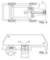
- FIG. 4is a plan view of a host vehicle in accordance with a first preferred embodiment of the present invention, diagrammatically presenting first and second radar sensors, a locator device, a memory storage device, a digital fusion processor (electronic control unit), an inclinometer, and a monitor;
- FIG. 5is an elevation view of an in-vehicle dashboard including the monitor, particularly illustrating warning indicia on the monitor;
- FIG. 6is a flowchart of a method of operation in accordance with a preferred embodiment of the invention, wherein data from the first and second radar sensors are combined in a data fusion module, and a minimum count is considered prior to over-pass determination;
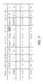
- FIG. 7is a chart representation of an exemplary track record stored by the memory storage device, in accordance with FIG. 2 ;
- FIG. 8is a flowchart of a second method of operation in accordance with a preferred embodiment of the invention, wherein trend analysis for the return signal strength and for the angle of sensory operation are also considered.
- the present inventionconcerns a collision avoidance system 10 adapted for use with host vehicles 12 , such as but not limited to automobiles, boats and aircrafts, and by an operator 14 ( FIGS. 1 through 4 ).
- the system 10fuses the return signals of at least two radar sensors 16 , 18 to estimate elevation information for at least one target (or detected object) 20 , such as the overpass shown in the illustrated embodiment.
- a digital fusion processor (DFP) 22consists of an electronic control unit programmably equipped to perform the various algorithms and functions described herein, or more preferably, a plurality of communicatively coupled (i.e., connected by hard-wire or by a wireless communication sub-system) control units configured to perform parallel computations as part of a neural network.
- DFPdigital fusion processor
- certain sub-routinesmay be performed by intermediate control units prior to delivery to the DFP 22 in series.
- each of the sensors 16 , 18may further include an electronic control unit configured to construct the return signal pattern, prior to fusion at the DFP 22 ; or a separate threat assessment controller (not shown) may be communicatively coupled to and configured to perform threat assessment after receiving fused data from the DFP 22 .
- the host vehicle 12includes sufficient electrical, software processing and communication bus sub-system capabilities necessary to effect the intended benefits of the system 10 . Said structural configurations are readily determinable by one of ordinary skill in the art, and therefore, will not be further discussed.
- the system 10includes two radar sensors 16 , 18 , each configured to laterally scan a forward environment in a single-degree of freedom ( FIG. 4 ); however, it is certainly within the ambit of the present invention to utilize an array of sensors oriented in multiple forward projections, so as to provide a more robust frontal detection system. It is also within the ambit of the invention, for a single sensor capable of transmitting a plurality of differing beams as further described herein to be utilized.
- the system 10includes at least one short range radar (SRR) sensor 16 , and at least one longer range radar (LRR) sensor 18 , wherein “short range,” may be defined, for example, as having a general operating range of 0 to 30 m, and “longer range” may be defined as having an operable range of 0 to 250 m.
- SRRshort range radar
- LRRlonger range radar
- the sensors 16 , 18are positioned at a preferred above-ground height (e.g., 45 cm) and oriented to desired angles of operation, ⁇ , so as to facilitate maximum coverage.
- a preferred above-ground heighte.g., 45 cm
- both the SRR and LRR sensorspreferably present normally horizontal angles of operation on flat surfaces ( FIG. 3 ); however, it is appreciated that the sensors 16 , 18 need not be congruently oriented.
- the sensors 16 , 18may have congruent ranges; that is to say, they may both present SRR or LRR sensors.
- the preferred sensors 16 , 18may be adjustably mounted to the vehicle 12 , so as to achieve a plurality of angles of operation or above-ground heights.
- the SRR sensor 16produces a first beam 24 having a first angle of inclination, ⁇ , equal to one-half the angle formed by the linearly diverging outer beam boundary 26 .
- amay be within the range 10 to 30 degrees, for typical clearance heights.
- the coverage areas 24 a , 28 a indicated in FIGS. 1 and 3are not as abrupt as shown, however, but generally indicate where the sensitivity of the sensors 16 , 18 drop by 3 dB.
- a Kalman filtermay be used to model and estimate the variance in coverage area caused by the sensitivity of the sensors 16 , 18 , so as to more accurately determine the angle of inclination and therefore, the target elevation data.
- the SRR sensor 16is configured to generate a first return signal (P SRR ) based on the relative distance between the sensor 16 and target 20 , and ⁇ .
- the LRR sensor 18produces a second more narrow beam 28 having a second angle of inclination, ⁇ , that is substantially less than ⁇ ( FIG. 3 ).
- ⁇may be within the range of 1 to 5 degrees.
- the LRR sensor 18is configured to generate a second return signal (P LRR ) based on the relative distance between the sensor 18 and target 20 , and ⁇ .
- a coverage height of 4.5 m for the SRR sensor beam 24results at a distance of 30 m from the SRR sensor 16 , while a coverage height of 1.2 m results for the LRR sensor beam 28 at the same distance; and at 150 m, the LRR sensor 18 produces a coverage height of 4.2 m.
- a target located 0.45 m above groundwill have a strong return signal for both sensors 16 , 18 but a target located 4 m above the ground will have a much larger relative return to the SRR sensor 16 than for the LRR sensor 18 .
- FIG. 7such a hyper elevated object is modeled; at ( 2 ) the SRR sensor 16 shows a strong return signal (P SRR ) and the LRR sensor 18 fails to register a return signal (P LRR ).
- the operable range of the SRR sensor 16must provide a maximum coverage length substantially greater than the minimum warning distance threshold necessary to provide a safe collision avoidance warning period. For example, based on vehicular braking capabilities and operator reaction times, where an SRR operable range of 30 m is presented, it is preferable to maintain speed limits that result in a warning distance threshold between 20 to 25 m.
- the present inventionfunctions to fuse information obtained from a plurality of single-dimensional radar sensors having differing beam angles of inclination and ranges to estimate the elevation of a target; and as such, may be used in conjunction with various types of radar sensors having a variety of bandwidths, resolutions, environmental applications, accuracies, power efficiencies, and sensitivities.
- Exemplary sensors suitable for use with the present inventioninclude Tyco M/A-COM's 24 GHz Ultra Wide Band (UWB) short range radar (SRR), and Tyco M/A-COM's 77 GHz long range radar (LRR).
- the DFP 22is configured to manipulate the return signals data (P SRR , P LRR ) to achieve a relative return signal value.
- range information of a particular target 20can be used to determine whether the target 20 presents an “in-path” object. For example, a simple ratio between the signals (e.g., P SRR /P LRR ), or a difference between the signals (P SRR ⁇ P LRR ) may be utilized to calculate the relative value. Where this value exceeds a minimum threshold, that is to say, where the short range radar signal is substantially greater than the long range radar signal, the DFP 22 will generally determine based on ⁇ (P SRR , P LRR ) that an overpass target has likely been detected. More detailed modes of operation are described below.
- the preferred system 10also includes a locator device 30 configured to locate the current position coordinates, Cp (e.g., latitude, Longitude, and height), and preferably the heading of the host vehicle 12 .
- the preferred locator device 30includes a Global Positioning System (GPS) receiver 32 communicatively coupled to orbiting satellites, and a dead-reckoning system.
- GPSGlobal Positioning System
- the locator device 30may utilize a network of cellular telephones, or a system using radio-frequency identification (RFID).
- the locator device 30is communicatively coupled to the DFP 22 through the receiver 32 , and is configured to determine and deliver to the DFP 22 the current position coordinates of the vehicle 12 .
- the DFP 22is configured to determine the absolute position of a target based on the detected range and azimuth of the target 20 , and the Cp.
- the preferred system 10also includes a memory storage device 34 that is communicatively coupled to the DFP 22 , so as to receive data from and be queriable by the DFP 22 ( FIG. 4 ).
- the storage device 34is configured to retain a track record of a given target by creating a new record when an object is detected at position coordinates not previously entered, and by modifying an existing record when the position coordinates of a detected object generally match a previously entered target ( FIG. 7 ).
- subsequent entries for the track at ( 1 . 5 ) and ( 2 )were recorded upon determination of generally matching (e.g., within a radius inclusive of the margin of error of the sensors 16 , 18 , plus a factor of safety) position coordinates.
- maintaining tracks of targets 20enables the performance of time-dependant statistical analysis, wherein past data is analyzed to be able to make probabilistic decisions on new data.
- a trend analysis of the return signal strengthmay be performed, for example, to distinguish approaching from departing objects.
- the storage device 34may be directly coupled to the sensors 16 , 18 where relative positioning tracks are maintained.
- an inclinometer 36is also included in the preferred system 10 and communicatively coupled to the DFP 22 ( FIG. 4 ).
- the DFP 22is further configured to consider the absolute change in the angle of operation, ⁇ , of the sensors 16 , 18 , as is determinable by measuring the slope of the vehicle 12 ( FIG. 3 a ).
- the preferred DFP 22causes the fusion module to terminate or modify; as it is appreciated that in these instances, the fusion module may receive erroneous range data and produce inaccurate target elevation estimates. For example, in FIG.
- the LRR sensor 18is able to detect the low-lying object 20 ; however, due to the vertical curvature of the roadway the range is shorter than the actual intermediate travel distance, the return signal strength is likely to be greater than it would be on a comparable flat surface, and an extrapolation of the beam height at that distance will result in an inaccurate estimate of the target elevation.
- a preferred method of operationbegins by receiving return signal data (P SRR , P LRR ) from the sensors 16 , 18 and communicating the data to a data fusion module autonomously performed by the DFP 22 .
- the fusion moduleis configured to determine at least one relative signal value based on the return signals (P SRR , P LRR ) received by the sensors 16 , 18 .
- the DFP 22is further configured to estimate the elevation of the target 20 based on the relative signal value(s) determined.
- the relative valueis compared to a plurality of pre-determined categories, preferably also stored in the DFP 22 , to determine a matching object type. For example, where the signal strength ratio (P SRR /P LRR ) is greater than 5, an “over-pass” object may be determined, and where the ratio is inclusively between 0.5 and 2, an “in-path” object may result.
- the system 10is further configured to execute a threat assessment module.
- a warningsuch as the visible indicia 38 shown on the monitor 40 in FIG. 5 is caused to be generated, and/or a mitigating maneuver, such as the actuation of a braking module (not shown) is initiated.
- a mitigating maneuversuch as the actuation of a braking module (not shown) is initiated. It is appreciated that the threat assessment module considers, among other things, the relative spacing between the host vehicle 12 and target 20 , as well as the speed of the host vehicle 12 .
- the preferred system 10is configured to issue a warning immediately, so that sufficient distance separates the vehicle 12 from the target 20 ( FIGS. 6 and 8 ). It is appreciated that, in this situation, the object 20 may present a newly introduced, side approaching, slender or other condition, such as a remote vehicle traversing the host vehicle path, which was not subject to long range detection.
- the DFP 22 and locator device 30are cooperatively configured to generally determine the absolute position coordinates of the sensors 16 , 18 , by attributing the coordinate position of the receiver 32 to the sensors 16 , 18 . More preferably, the length and width dimensions of the host vehicle 12 and the locations of the sensors 16 , 18 relative to the receiver 32 are pre-determined and considered so that the actual coordinate positions of the sensors 16 , 18 can be determined by the DFP 22 .
- the absolute position coordinates of the target 20can be calculated by trigonometrically considering the azimuth and range or relative distance vector between the sensors 16 , 18 and target 20 . As previously mentioned, determining the positioning of the target 20 is necessary to compile a track record, prepare trend analysis, and aggregate relative signal values derived for a particular target.
- FIG. 6A more detailed method of operation is presented in FIG. 6 , which utilizes a counter to determine a plurality of over-pass determinations prior to making a final decision.
- the methodbegins once an object is detected by either sensor at a step 102 .
- the host vehicle position coordinates, Cp, at the instant of object detectionare obtained.
- the range and azimuth of the target 20are determined based on the return signal data received; and the absolute position coordinates of the target 20 based on Cp, and the height of the angle of inclination at the object 20 is determined.
- the threat assessment moduledetermines whether the range is within an immediate warning distance. If not, the fusion module determines whether the target 20 is existing at step 108 by comparing its position coordinates to the existing tracks. If not an existing object, a new track record is created and a y-value associated with that track is set to “0” at step 110 b ; else the time of detection, range, azimuth and the height of the angle of inclination for each sensor 16 , 18 are caused to be stored in memory at step 110 a .
- a plurality of overpass predictive relationshipsare considered ( FIG. 6 ). If at least one, and more preferably, two relationships are met, then at a step 114 the counter incrementally progresses and then returns to step 102 ; else, the method proceeds directly to step 102 without advancing the counter.
- the fusion moduledetermines whether the object is existing at step 116 . If the target 20 is an existing object, then the y-value is retrieved for the track and compared to a minimum count (e.g., 2) at step 118 a ; else a warning is issued at step 118 b . If the y-value is greater than the minimum count, then the target is deemed an overpass object and the warning is not issued at step 120 . Alternatively, notice of an “over-pass object” may be generated at step 120 instead. Otherwise, the method proceeds to step 118 b , where a warning of a potential “in-path object” is issued.
- a minimum counte.g., 2
- Steps 200 through 206 of this methodare similar to steps 100 through 106 of the method of part C, except that the instantaneous angles of operation, ⁇ , measured by the inclinometer 36 during object detection is also obtained at step 202 .
- Steps 210 through 216likewise, match steps 108 through 114 .
- a function of ⁇is compared to a maximum threshold to determine whether the vehicle is managing a significant vertical curve. If the change in ⁇ indicates a vertical curve greater than a minimum threshold, then the reading is ignored as the method returns directly to step 202 ; otherwise the method proceeds to step 210 .
- step 218if the target within the warning distance is deemed to be an existing object, the method proceeds to step 220 a , where the immediate trend in return signal strengths (P SRR and P LRR ) are considered to determine whether the target (regardless of whether in-path or overpass) is departing or approaching; else the method proceeds to step 220 b , where the warning is issued. If deemed departing at step 220 a (i.e., P SSR (t(x)) ⁇ P SSR (t(x ⁇ 1)) is negative), the method proceeds directly to step 224 where the warning is not issued.
- P SSRimmediate trend in return signal strengths
- step 222the y-value is retrieved and compared to a minimum count to determine an overpass condition. Where the y-value is greater than the count an over-pass is deemed and the warning is not issued at step 224 . Where the y-value is less than or equal to the count, however, the method returns to step 220 b and a warning is issued.
Landscapes
- Engineering & Computer Science (AREA)
- Radar, Positioning & Navigation (AREA)
- Remote Sensing (AREA)
- Physics & Mathematics (AREA)
- General Physics & Mathematics (AREA)
- Computer Networks & Wireless Communication (AREA)
- Electromagnetism (AREA)
- Radar Systems Or Details Thereof (AREA)
Abstract
Description
Claims (10)
Priority Applications (3)
| Application Number | Priority Date | Filing Date | Title |
|---|---|---|---|
| US11/769,017US7592945B2 (en) | 2007-06-27 | 2007-06-27 | Method of estimating target elevation utilizing radar data fusion |
| DE102008029613.9ADE102008029613B4 (en) | 2007-06-27 | 2008-06-23 | Method for estimating the elevation of a target object using radar data fusion |
| CN2008101285506ACN101334475B (en) | 2007-06-27 | 2008-06-27 | Method of estimating target elevation utilizing radar data fusion |
Applications Claiming Priority (1)
| Application Number | Priority Date | Filing Date | Title |
|---|---|---|---|
| US11/769,017US7592945B2 (en) | 2007-06-27 | 2007-06-27 | Method of estimating target elevation utilizing radar data fusion |
Publications (2)
| Publication Number | Publication Date |
|---|---|
| US20090002222A1 US20090002222A1 (en) | 2009-01-01 |
| US7592945B2true US7592945B2 (en) | 2009-09-22 |
Family
ID=40149247
Family Applications (1)
| Application Number | Title | Priority Date | Filing Date |
|---|---|---|---|
| US11/769,017Active2027-11-09US7592945B2 (en) | 2007-06-27 | 2007-06-27 | Method of estimating target elevation utilizing radar data fusion |
Country Status (3)
| Country | Link |
|---|---|
| US (1) | US7592945B2 (en) |
| CN (1) | CN101334475B (en) |
| DE (1) | DE102008029613B4 (en) |
Cited By (29)
| Publication number | Priority date | Publication date | Assignee | Title |
|---|---|---|---|---|
| US20050240330A1 (en)* | 2002-11-21 | 2005-10-27 | Lucas Automotive Gmbh | System for influencing the speed of a motor vehicle |
| US20080189039A1 (en)* | 2007-02-06 | 2008-08-07 | Gm Global Technology Operations, Inc. | Collision avoidance system and method of detecting overpass locations using data fusion |
| US20080272958A1 (en)* | 2004-02-18 | 2008-11-06 | Delphi Technologies, Inc. | Collision detection system and method of estimating target crossing location |
| US20090195465A1 (en)* | 2008-01-31 | 2009-08-06 | Denso International America, Inc. | Dual transmitting antenna system |
| US20100103023A1 (en)* | 2008-10-28 | 2010-04-29 | Toyota Jidosha Kabushiki Kaisha | Radar system |
| US20110025548A1 (en)* | 2009-07-31 | 2011-02-03 | Gm Global Technology Operations, Inc. | System and method for vehicle sensor fusion |
| US20110169682A1 (en)* | 2008-10-09 | 2011-07-14 | The Ohio State University Research Foundation | Lateral wave radar system for forward detection |
| US20110221628A1 (en)* | 2010-03-15 | 2011-09-15 | Honda Elesys Co., Ltd. | Radar apparatus and computer program |
| US20110238309A1 (en)* | 2008-12-09 | 2011-09-29 | Toyota Jidosha Kabushiki Kaisha | Object detection apparatus and object detection method |
| US20110285573A1 (en)* | 2010-05-18 | 2011-11-24 | Mando Corporation | Integrated radar system and vehicle control system |
| US20110301845A1 (en)* | 2009-01-29 | 2011-12-08 | Toyota Jidosha Kabushiki Kaisha | Object recognition device and object recognition method |
| US20120169526A1 (en)* | 2009-09-25 | 2012-07-05 | Valeo Schalter Und Sensoren Gmbh | Driver assistance system for a vehicle, vehicle having a driver assistance system, and method for assisting a driver in driving a vehicle |
| US20120235857A1 (en)* | 2011-03-16 | 2012-09-20 | Electronics And Telecommunications Research Institute | Radar apparatus supporting short and long range radar operation |
| US20130154871A1 (en)* | 2011-12-14 | 2013-06-20 | Ford Global Technologies, Llc | Tilt sensing system for automotive radar |
| US8825260B1 (en)* | 2013-07-23 | 2014-09-02 | Google Inc. | Object and ground segmentation from a sparse one-dimensional range data |
| US9044543B2 (en) | 2012-07-17 | 2015-06-02 | Elwha Llc | Unmanned device utilization methods and systems |
| US9061102B2 (en) | 2012-07-17 | 2015-06-23 | Elwha Llc | Unmanned device interaction methods and systems |
| US20150309171A1 (en)* | 2014-04-25 | 2015-10-29 | Fujitsu Ten Limited | Radar apparatus |
| US20160054442A1 (en)* | 2014-08-20 | 2016-02-25 | Wistron Neweb Corporation | Pre-warning Method and Vehicle Radar System |
| US9517755B1 (en)* | 2015-05-25 | 2016-12-13 | Automotive Research & Testing Center | Autonomous braking system and autonomous braking method |
| US9784831B2 (en) | 2014-08-20 | 2017-10-10 | Wistron Neweb Corporation | Pre-warning method and vehicle radar system |
| US20170363720A1 (en)* | 2016-06-17 | 2017-12-21 | Fujitsu Ten Limited | Radar device and signal processing method |
| US20180059216A1 (en)* | 2016-08-26 | 2018-03-01 | Infineon Technologies Ag | Receive chain configuration for concurrent multi-mode radar operation |
| US9922282B2 (en) | 2015-07-21 | 2018-03-20 | Limitless Computing, Inc. | Automated readiness evaluation system (ARES) for use with an unmanned aircraft system (UAS) |
| US10175352B2 (en)* | 2015-05-12 | 2019-01-08 | Maxlinear, Inc. | Scalable architecture for an automotive radar system |
| US10222803B2 (en) | 2017-06-02 | 2019-03-05 | Aptiv Technologies Limited | Determining objects of interest for active cruise control |
| CN109490864A (en)* | 2018-12-18 | 2019-03-19 | 安徽四创电子股份有限公司 | A kind of target range three-dimensional coordinates measurement radar network composite test macro |
| US11267465B1 (en) | 2019-09-04 | 2022-03-08 | Ford Global Technologies, Llc | Enhanced threat assessment |
| US11762060B2 (en) | 2020-08-27 | 2023-09-19 | Aptiv Technologies Limited | Height-estimation of objects using radar |
Families Citing this family (42)
| Publication number | Priority date | Publication date | Assignee | Title |
|---|---|---|---|---|
| CN102409123A (en)* | 2010-09-25 | 2012-04-11 | 宝山钢铁股份有限公司 | Blast furnace burden face imaging system based on multisource heterogeneous data fusion |
| US8604918B2 (en)* | 2010-11-10 | 2013-12-10 | Hyundai Motor Company | System and method for detecting a vehicle in the vicinity by using wireless communication |
| JP5554688B2 (en) | 2010-11-19 | 2014-07-23 | 株式会社デンソー | Radar equipment |
| JP2012112671A (en)* | 2010-11-19 | 2012-06-14 | Furuno Electric Co Ltd | Detection device, radar device, detection method and detection program |
| CN102064799B (en)* | 2010-12-31 | 2014-06-04 | 南京理工大学 | Method for designing DCMFK (Debiased Converted Measurement Kalman filter) based on FPGA (Field Programmable Gate Array) |
| DE102011077333A1 (en)* | 2011-06-10 | 2012-12-27 | Robert Bosch Gmbh | Driver assistance system with object detection |
| CN102663492A (en)* | 2012-03-19 | 2012-09-12 | 南京理工大学常熟研究院有限公司 | Maneuvering target tracking system based on nerve network data fusion |
| FR2989204B1 (en)* | 2012-04-06 | 2014-04-11 | Thales Sa | METHOD FOR DETERMINING AN INSTANT PROBABLE OR ANTICIPATED OCCUPANCY AREA OF AN AIRCRAFT IN AN AIRPORT NAVIGATION AREA |
| JP6035862B2 (en)* | 2012-05-18 | 2016-11-30 | トヨタ自動車株式会社 | Object determination device and collision avoidance support device |
| JP6114530B2 (en)* | 2012-10-16 | 2017-04-12 | ルネサスエレクトロニクス株式会社 | Display device and display device driver |
| DE102012220773A1 (en) | 2012-11-14 | 2014-05-15 | Robert Bosch Gmbh | Device and method for elevation angle determination in a radar system |
| JP5835242B2 (en)* | 2013-02-01 | 2015-12-24 | 株式会社デンソー | Vehicle safety control system |
| DE102013104443B4 (en)* | 2013-04-30 | 2022-03-17 | Jenoptik Robot Gmbh | Traffic monitoring system for measuring the speed and allocation of moving vehicles in a multi-target recording module |
| CN103456190A (en)* | 2013-09-04 | 2013-12-18 | 蔡新梅 | Ship collision avoidance device based on UWB |
| US9546876B2 (en)* | 2013-10-30 | 2017-01-17 | Ford Global Technologies, Llc | System for determining clearance of approaching overhead structure |
| DE102014201026A1 (en)* | 2014-01-21 | 2015-07-23 | Robert Bosch Gmbh | Method for angle estimation and radar sensor for motor vehicles |
| EP2902802B1 (en)* | 2014-01-31 | 2016-10-26 | S.M.S. Smart Microwave Sensors GmbH | Sensor device |
| EP3194242A1 (en) | 2014-09-19 | 2017-07-26 | ALSTOM Transport Technologies | System and method for avoiding a collision for a vehicle |
| US20160223649A1 (en)* | 2015-01-30 | 2016-08-04 | Robert Bosch Gmbh | Systems and methods for radar vertical misalignment detection |
| US9766336B2 (en)* | 2015-03-16 | 2017-09-19 | Here Global B.V. | Vehicle obstruction detection |
| US9599706B2 (en)* | 2015-04-06 | 2017-03-21 | GM Global Technology Operations LLC | Fusion method for cross traffic application using radars and camera |
| JP6468353B2 (en)* | 2015-05-14 | 2019-02-13 | 富士通株式会社 | Air conditioner, sensor unit, and control system and control method for air conditioner |
| JP6613624B2 (en)* | 2015-05-27 | 2019-12-04 | いすゞ自動車株式会社 | Discrimination method and discrimination device |
| DE102015213701B4 (en) | 2015-07-21 | 2025-08-07 | Robert Bosch Gmbh | Sensor system for a vehicle to detect bridges or tunnel entrances |
| CN105584413B (en)* | 2016-03-04 | 2018-01-12 | 武汉理工大学 | A kind of apparatus and method for preventing vehicle collision |
| DE102016207463A1 (en)* | 2016-04-29 | 2017-11-02 | Robert Bosch Gmbh | Method and device for operating at least one vehicle with respect to at least one passable object in the vicinity of the at least one vehicle |
| DE102016108756A1 (en)* | 2016-05-12 | 2017-11-16 | Valeo Schalter Und Sensoren Gmbh | Radar sensor device for a motor vehicle, driver assistance system, motor vehicle and method for detecting an object |
| JP6858067B2 (en)* | 2016-06-17 | 2021-04-14 | 株式会社デンソーテン | Radar device and control method of radar device |
| CN106960588B (en)* | 2017-03-24 | 2019-08-06 | 奇瑞汽车股份有限公司 | Method and device is determined based on the vehicle attitude of dedicated short-range communication |
| US10347141B2 (en)* | 2017-04-26 | 2019-07-09 | Honeywell International Inc. | System and method for transmitting obstacle alerts to aircraft from a ground based database |
| JP6856452B2 (en)* | 2017-06-14 | 2021-04-07 | トヨタ自動車株式会社 | Target judgment device and driving support system |
| US20190016315A1 (en)* | 2017-07-12 | 2019-01-17 | Aptiv Technologies Limited | Automated braking system |
| FR3076045A1 (en)* | 2017-12-22 | 2019-06-28 | Orange | METHOD FOR MONITORING AN ENVIRONMENT OF A FIRST ELEMENT POSITIONED AT THE LEVEL OF A CIRCULATION PATH, AND ASSOCIATED SYSTEM |
| JP7092529B2 (en)* | 2018-03-16 | 2022-06-28 | 株式会社デンソーテン | Radar device and control method of radar device |
| JP6596534B2 (en)* | 2018-04-06 | 2019-10-23 | 株式会社デンソーテン | Radar apparatus, vehicle control system, and signal processing method |
| DE102018205322A1 (en)* | 2018-04-10 | 2019-10-10 | Audi Ag | Method and control device for detecting a malfunction of at least one environmental sensor of a motor vehicle |
| WO2020056236A1 (en)* | 2018-09-14 | 2020-03-19 | Aondevices, Inc. | System architecture and embedded circuit to locate a lost portable device using voice command |
| KR102818482B1 (en)* | 2019-01-22 | 2025-06-10 | 현대모비스 주식회사 | Apparatus and method for estimating the number of targets |
| WO2021171638A1 (en)* | 2020-02-25 | 2021-09-02 | 古河電気工業株式会社 | Radar system, processing method, and processing program |
| CN112180372A (en)* | 2020-08-19 | 2021-01-05 | 福瑞泰克智能系统有限公司 | A target detection method, device and radar system based on dual-angle radar |
| US12111389B2 (en) | 2020-09-21 | 2024-10-08 | Argo AI, LLC | Radar elevation angle validation |
| JP7560397B2 (en)* | 2021-03-25 | 2024-10-02 | パナソニックオートモーティブシステムズ株式会社 | OBJECT IDENTIFICATION DEVICE, VEHICLE, AND OBJECT IDENTIFICATION METHOD |
Citations (9)
| Publication number | Priority date | Publication date | Assignee | Title |
|---|---|---|---|---|
| US6429804B1 (en)* | 1999-11-24 | 2002-08-06 | Fujitsu Ten Limited | Motor-vehicle-mounted radar apparatus |
| US20020150304A1 (en)* | 2001-04-12 | 2002-10-17 | Norman Ockman | System for morphological image fusion and change detection |
| US20020191198A1 (en)* | 2001-06-18 | 2002-12-19 | Dunne Jeremy G. | Upper stem diameter measurement and basal area determination device and method for utilization in timber cruising applications |
| US20040119633A1 (en)* | 2000-02-08 | 2004-06-24 | Cambridge Consultants Limited | Methods and apparatus for obtaining positional information |
| US20060027404A1 (en)* | 2002-08-09 | 2006-02-09 | Intersense, Inc., A Delaware Coroporation | Tracking, auto-calibration, and map-building system |
| US20060126927A1 (en)* | 2004-11-30 | 2006-06-15 | Vesely Michael A | Horizontal perspective representation |
| US7100726B2 (en)* | 2003-05-29 | 2006-09-05 | Hyundai Motor Company | Apparatus for controlling distance between vehicles |
| US20070043491A1 (en)* | 2005-08-18 | 2007-02-22 | Christian Goerick | Driver assistance system |
| US20080111733A1 (en)* | 2006-11-15 | 2008-05-15 | M/A-Com, Inc. | Method and Apparatus For Discriminating With Respect to Low Elevation Target Objects |
Family Cites Families (5)
| Publication number | Priority date | Publication date | Assignee | Title |
|---|---|---|---|---|
| DE19543813A1 (en) | 1995-11-24 | 1997-05-28 | Bosch Gmbh Robert | Radar system, in particular motor vehicle radar system |
| DE19650863C1 (en) | 1996-12-07 | 1998-04-16 | Bosch Gmbh Robert | Method of detecting distance sensor vertical adjustment error |
| JPH10221451A (en) | 1997-02-04 | 1998-08-21 | Toyota Motor Corp | Radar equipment for vehicles |
| DE10260855A1 (en) | 2002-12-23 | 2004-07-08 | Robert Bosch Gmbh | Method for recognizing object constellations based on distance signals |
| DE102004021561A1 (en) | 2004-05-03 | 2005-12-08 | Daimlerchrysler Ag | Object recognition system for a motor vehicle |
- 2007
- 2007-06-27USUS11/769,017patent/US7592945B2/enactiveActive
- 2008
- 2008-06-23DEDE102008029613.9Apatent/DE102008029613B4/enactiveActive
- 2008-06-27CNCN2008101285506Apatent/CN101334475B/enactiveActive
Patent Citations (9)
| Publication number | Priority date | Publication date | Assignee | Title |
|---|---|---|---|---|
| US6429804B1 (en)* | 1999-11-24 | 2002-08-06 | Fujitsu Ten Limited | Motor-vehicle-mounted radar apparatus |
| US20040119633A1 (en)* | 2000-02-08 | 2004-06-24 | Cambridge Consultants Limited | Methods and apparatus for obtaining positional information |
| US20020150304A1 (en)* | 2001-04-12 | 2002-10-17 | Norman Ockman | System for morphological image fusion and change detection |
| US20020191198A1 (en)* | 2001-06-18 | 2002-12-19 | Dunne Jeremy G. | Upper stem diameter measurement and basal area determination device and method for utilization in timber cruising applications |
| US20060027404A1 (en)* | 2002-08-09 | 2006-02-09 | Intersense, Inc., A Delaware Coroporation | Tracking, auto-calibration, and map-building system |
| US7100726B2 (en)* | 2003-05-29 | 2006-09-05 | Hyundai Motor Company | Apparatus for controlling distance between vehicles |
| US20060126927A1 (en)* | 2004-11-30 | 2006-06-15 | Vesely Michael A | Horizontal perspective representation |
| US20070043491A1 (en)* | 2005-08-18 | 2007-02-22 | Christian Goerick | Driver assistance system |
| US20080111733A1 (en)* | 2006-11-15 | 2008-05-15 | M/A-Com, Inc. | Method and Apparatus For Discriminating With Respect to Low Elevation Target Objects |
Cited By (55)
| Publication number | Priority date | Publication date | Assignee | Title |
|---|---|---|---|---|
| US7840330B2 (en)* | 2002-11-21 | 2010-11-23 | Lucas Automotive Gmbh | System for influencing the speed of a motor vehicle |
| US20050240330A1 (en)* | 2002-11-21 | 2005-10-27 | Lucas Automotive Gmbh | System for influencing the speed of a motor vehicle |
| US20080272958A1 (en)* | 2004-02-18 | 2008-11-06 | Delphi Technologies, Inc. | Collision detection system and method of estimating target crossing location |
| US7777618B2 (en)* | 2004-02-18 | 2010-08-17 | Delphi Technologies, Inc. | Collision detection system and method of estimating target crossing location |
| US20080189039A1 (en)* | 2007-02-06 | 2008-08-07 | Gm Global Technology Operations, Inc. | Collision avoidance system and method of detecting overpass locations using data fusion |
| US8935086B2 (en)* | 2007-02-06 | 2015-01-13 | GM Global Technology Operations LLC | Collision avoidance system and method of detecting overpass locations using data fusion |
| US7973700B2 (en)* | 2008-01-31 | 2011-07-05 | Denso International America, Inc. | Dual transmitting antenna system |
| US20090195465A1 (en)* | 2008-01-31 | 2009-08-06 | Denso International America, Inc. | Dual transmitting antenna system |
| US20110169682A1 (en)* | 2008-10-09 | 2011-07-14 | The Ohio State University Research Foundation | Lateral wave radar system for forward detection |
| US8334802B2 (en)* | 2008-10-28 | 2012-12-18 | Toyota Jidosha Kabushiki Kaisha | Radar system |
| US20100103023A1 (en)* | 2008-10-28 | 2010-04-29 | Toyota Jidosha Kabushiki Kaisha | Radar system |
| US9283910B2 (en)* | 2008-12-09 | 2016-03-15 | Toyota Jidosha Kabushiki Kaisha | Object detection apparatus and object detection method |
| US20110238309A1 (en)* | 2008-12-09 | 2011-09-29 | Toyota Jidosha Kabushiki Kaisha | Object detection apparatus and object detection method |
| US20110301845A1 (en)* | 2009-01-29 | 2011-12-08 | Toyota Jidosha Kabushiki Kaisha | Object recognition device and object recognition method |
| US8818703B2 (en)* | 2009-01-29 | 2014-08-26 | Toyota Jidosha Kabushiki Kaisha | Object recognition device and object recognition method |
| US20110025548A1 (en)* | 2009-07-31 | 2011-02-03 | Gm Global Technology Operations, Inc. | System and method for vehicle sensor fusion |
| US20120169526A1 (en)* | 2009-09-25 | 2012-07-05 | Valeo Schalter Und Sensoren Gmbh | Driver assistance system for a vehicle, vehicle having a driver assistance system, and method for assisting a driver in driving a vehicle |
| US9174650B2 (en)* | 2009-09-25 | 2015-11-03 | Valeo Schalter Und Sensoren Gmbh | Driver assistance system for a vehicle, vehicle having a driver assistance system, and method for assisting a driver in driving a vehicle |
| US8558733B2 (en)* | 2010-03-15 | 2013-10-15 | Honda Elesys Co., Ltd. | Radar apparatus and computer program |
| US20110221628A1 (en)* | 2010-03-15 | 2011-09-15 | Honda Elesys Co., Ltd. | Radar apparatus and computer program |
| US20110285573A1 (en)* | 2010-05-18 | 2011-11-24 | Mando Corporation | Integrated radar system and vehicle control system |
| US20120235857A1 (en)* | 2011-03-16 | 2012-09-20 | Electronics And Telecommunications Research Institute | Radar apparatus supporting short and long range radar operation |
| US8902103B2 (en)* | 2011-03-16 | 2014-12-02 | Electronics And Telecommunications Research Institute | Radar apparatus supporting short and long range radar operation |
| US20130154871A1 (en)* | 2011-12-14 | 2013-06-20 | Ford Global Technologies, Llc | Tilt sensing system for automotive radar |
| US9044543B2 (en) | 2012-07-17 | 2015-06-02 | Elwha Llc | Unmanned device utilization methods and systems |
| US9061102B2 (en) | 2012-07-17 | 2015-06-23 | Elwha Llc | Unmanned device interaction methods and systems |
| US9798325B2 (en) | 2012-07-17 | 2017-10-24 | Elwha Llc | Unmanned device interaction methods and systems |
| US9713675B2 (en) | 2012-07-17 | 2017-07-25 | Elwha Llc | Unmanned device interaction methods and systems |
| US9254363B2 (en) | 2012-07-17 | 2016-02-09 | Elwha Llc | Unmanned device interaction methods and systems |
| US9733644B2 (en) | 2012-07-17 | 2017-08-15 | Elwha Llc | Unmanned device interaction methods and systems |
| US10019000B2 (en) | 2012-07-17 | 2018-07-10 | Elwha Llc | Unmanned device utilization methods and systems |
| US9097804B1 (en) | 2013-07-23 | 2015-08-04 | Google Inc. | Object and ground segmentation from a sparse one-dimensional range data |
| US8825260B1 (en)* | 2013-07-23 | 2014-09-02 | Google Inc. | Object and ground segmentation from a sparse one-dimensional range data |
| US20150309171A1 (en)* | 2014-04-25 | 2015-10-29 | Fujitsu Ten Limited | Radar apparatus |
| DE102015105078B4 (en) | 2014-04-25 | 2023-08-10 | Fujitsu Ten Limited | radar device |
| US10001560B2 (en)* | 2014-04-25 | 2018-06-19 | Fujitsu Ten Limited | Radar apparatus |
| US10162052B2 (en)* | 2014-08-20 | 2018-12-25 | Wistron Neweb Corporation | Pre-warning method and vehicle radar system |
| US20160054442A1 (en)* | 2014-08-20 | 2016-02-25 | Wistron Neweb Corporation | Pre-warning Method and Vehicle Radar System |
| US9784831B2 (en) | 2014-08-20 | 2017-10-10 | Wistron Neweb Corporation | Pre-warning method and vehicle radar system |
| US10613221B2 (en)* | 2015-05-12 | 2020-04-07 | Maxlinear, Inc. | Scalable architecture for an automotive radar system |
| US10175352B2 (en)* | 2015-05-12 | 2019-01-08 | Maxlinear, Inc. | Scalable architecture for an automotive radar system |
| US9517755B1 (en)* | 2015-05-25 | 2016-12-13 | Automotive Research & Testing Center | Autonomous braking system and autonomous braking method |
| US9922282B2 (en) | 2015-07-21 | 2018-03-20 | Limitless Computing, Inc. | Automated readiness evaluation system (ARES) for use with an unmanned aircraft system (UAS) |
| US10115048B2 (en) | 2015-07-21 | 2018-10-30 | Limitless Computing, Inc. | Method and system for configurable and scalable unmanned aerial vehicles and systems |
| US11126903B2 (en) | 2015-07-21 | 2021-09-21 | Limitless Computing, Inc. | Method and system for configurable and scalable unmanned aerial vehicles and systems |
| US10712429B2 (en)* | 2016-06-17 | 2020-07-14 | Fujitsu Ten Limited | Radar device and signal processing method |
| US20170363720A1 (en)* | 2016-06-17 | 2017-12-21 | Fujitsu Ten Limited | Radar device and signal processing method |
| US20180059216A1 (en)* | 2016-08-26 | 2018-03-01 | Infineon Technologies Ag | Receive chain configuration for concurrent multi-mode radar operation |
| US10620298B2 (en)* | 2016-08-26 | 2020-04-14 | Infineon Technologies Ag | Receive chain configuration for concurrent multi-mode radar operation |
| US10996312B2 (en)* | 2016-08-26 | 2021-05-04 | Infineon Technologies Ag | Receive chain configuration for concurrent multi-mode radar operation |
| US10222803B2 (en) | 2017-06-02 | 2019-03-05 | Aptiv Technologies Limited | Determining objects of interest for active cruise control |
| CN109490864A (en)* | 2018-12-18 | 2019-03-19 | 安徽四创电子股份有限公司 | A kind of target range three-dimensional coordinates measurement radar network composite test macro |
| CN109490864B (en)* | 2018-12-18 | 2021-09-28 | 安徽四创电子股份有限公司 | Radar networking test system for measuring three coordinates of target range |
| US11267465B1 (en) | 2019-09-04 | 2022-03-08 | Ford Global Technologies, Llc | Enhanced threat assessment |
| US11762060B2 (en) | 2020-08-27 | 2023-09-19 | Aptiv Technologies Limited | Height-estimation of objects using radar |
Also Published As
| Publication number | Publication date |
|---|---|
| US20090002222A1 (en) | 2009-01-01 |
| CN101334475A (en) | 2008-12-31 |
| DE102008029613B4 (en) | 2021-10-28 |
| CN101334475B (en) | 2012-02-08 |
| DE102008029613A1 (en) | 2009-01-22 |
Similar Documents
| Publication | Publication Date | Title |
|---|---|---|
| US7592945B2 (en) | Method of estimating target elevation utilizing radar data fusion | |
| US6832156B2 (en) | Methods and apparatus for stationary object detection | |
| US6404328B1 (en) | Discrimination of detected objects in a vehicle path | |
| US6675094B2 (en) | Path prediction system and method | |
| US8935086B2 (en) | Collision avoidance system and method of detecting overpass locations using data fusion | |
| US9117098B2 (en) | On-board traffic density estimator | |
| EP1540564B1 (en) | Collision avoidance and warning system, method for preventing collisions | |
| EP1094336B1 (en) | Object recognition apparatus | |
| US6674394B1 (en) | Method for determining object location from side-looking sensor data | |
| EP1273930B1 (en) | A method for collision avoidance and collision mitigation | |
| KR102013224B1 (en) | Autonomous Emergencyy Braking System and Controlling Method Thereof | |
| JP2000502807A (en) | Method and signal processing for signal processing in an automotive radar system | |
| CN101625797A (en) | Early warning method when automobile closes at high speed and early warning device | |
| WO2023025777A1 (en) | Automotive sensor fusion of radar, lidar, camera systems with improved safety by use of machine learning | |
| CN111873906A (en) | Vehicle side door opening angle early warning method, system, medium and vehicle-mounted terminal | |
| CN109581390B (en) | Terrain detection method, system, terminal and storage medium based on ultrasonic radar | |
| US20100238066A1 (en) | Method and system for generating a target alert | |
| US20190086529A1 (en) | Variable range and frame-rate radar operation for automated vehicle | |
| US12422545B2 (en) | Detection and localization of non-line-of-sight objects using multipath radar reflections and map data | |
| US11435442B2 (en) | Method for capturing a surrounding region of a motor vehicle with object classification, control device, driver assistance system and motor vehicle | |
| US11798417B2 (en) | Driving assistance device | |
| JP2005258941A (en) | Obstacle detection device | |
| CN114578382A (en) | Automobile surrounding environment real-time detection method and system based on artificial intelligence | |
| CN114034357A (en) | Accumulated water depth detection method and device and storage medium | |
| JPWO2020075682A1 (en) | Electronic devices, control methods for electronic devices, and control programs for electronic devices |
Legal Events
| Date | Code | Title | Description |
|---|---|---|---|
| AS | Assignment | Owner name:GM GLOBAL TECHNOLOGY OPERATIONS, INC., MICHIGAN Free format text:ASSIGNMENT OF ASSIGNORS INTEREST;ASSIGNORS:COLBURN, JOSEPH S.;ALTAN, OSMAN D.;GEARY, KEVIN;AND OTHERS;REEL/FRAME:019954/0756 Effective date:20070619 | |
| AS | Assignment | Owner name:UNITED STATES DEPARTMENT OF THE TREASURY, DISTRICT Free format text:SECURITY AGREEMENT;ASSIGNOR:GM GLOBAL TECHNOLOGY OPERATIONS, INC.;REEL/FRAME:022201/0448 Effective date:20081231 Owner name:UNITED STATES DEPARTMENT OF THE TREASURY,DISTRICT Free format text:SECURITY AGREEMENT;ASSIGNOR:GM GLOBAL TECHNOLOGY OPERATIONS, INC.;REEL/FRAME:022201/0448 Effective date:20081231 | |
| AS | Assignment | Owner name:CITICORP USA, INC. AS AGENT FOR BANK PRIORITY SECU Free format text:SECURITY AGREEMENT;ASSIGNOR:GM GLOBAL TECHNOLOGY OPERATIONS, INC.;REEL/FRAME:022553/0540 Effective date:20090409 Owner name:CITICORP USA, INC. AS AGENT FOR HEDGE PRIORITY SEC Free format text:SECURITY AGREEMENT;ASSIGNOR:GM GLOBAL TECHNOLOGY OPERATIONS, INC.;REEL/FRAME:022553/0540 Effective date:20090409 | |
| AS | Assignment | Owner name:GM GLOBAL TECHNOLOGY OPERATIONS, INC., MICHIGAN Free format text:RELEASE BY SECURED PARTY;ASSIGNOR:UNITED STATES DEPARTMENT OF THE TREASURY;REEL/FRAME:023124/0563 Effective date:20090709 Owner name:GM GLOBAL TECHNOLOGY OPERATIONS, INC.,MICHIGAN Free format text:RELEASE BY SECURED PARTY;ASSIGNOR:UNITED STATES DEPARTMENT OF THE TREASURY;REEL/FRAME:023124/0563 Effective date:20090709 | |
| AS | Assignment | Owner name:GM GLOBAL TECHNOLOGY OPERATIONS, INC., MICHIGAN Free format text:RELEASE BY SECURED PARTY;ASSIGNORS:CITICORP USA, INC. AS AGENT FOR BANK PRIORITY SECURED PARTIES;CITICORP USA, INC. AS AGENT FOR HEDGE PRIORITY SECURED PARTIES;REEL/FRAME:023155/0663 Effective date:20090814 Owner name:GM GLOBAL TECHNOLOGY OPERATIONS, INC.,MICHIGAN Free format text:RELEASE BY SECURED PARTY;ASSIGNORS:CITICORP USA, INC. AS AGENT FOR BANK PRIORITY SECURED PARTIES;CITICORP USA, INC. AS AGENT FOR HEDGE PRIORITY SECURED PARTIES;REEL/FRAME:023155/0663 Effective date:20090814 | |
| AS | Assignment | Owner name:UNITED STATES DEPARTMENT OF THE TREASURY, DISTRICT Free format text:SECURITY AGREEMENT;ASSIGNOR:GM GLOBAL TECHNOLOGY OPERATIONS, INC.;REEL/FRAME:023156/0264 Effective date:20090710 Owner name:UNITED STATES DEPARTMENT OF THE TREASURY,DISTRICT Free format text:SECURITY AGREEMENT;ASSIGNOR:GM GLOBAL TECHNOLOGY OPERATIONS, INC.;REEL/FRAME:023156/0264 Effective date:20090710 | |
| AS | Assignment | Owner name:UAW RETIREE MEDICAL BENEFITS TRUST, MICHIGAN Free format text:SECURITY AGREEMENT;ASSIGNOR:GM GLOBAL TECHNOLOGY OPERATIONS, INC.;REEL/FRAME:023162/0140 Effective date:20090710 Owner name:UAW RETIREE MEDICAL BENEFITS TRUST,MICHIGAN Free format text:SECURITY AGREEMENT;ASSIGNOR:GM GLOBAL TECHNOLOGY OPERATIONS, INC.;REEL/FRAME:023162/0140 Effective date:20090710 | |
| STCF | Information on status: patent grant | Free format text:PATENTED CASE | |
| AS | Assignment | Owner name:GM GLOBAL TECHNOLOGY OPERATIONS, INC., MICHIGAN Free format text:RELEASE BY SECURED PARTY;ASSIGNOR:UNITED STATES DEPARTMENT OF THE TREASURY;REEL/FRAME:025245/0656 Effective date:20100420 | |
| AS | Assignment | Owner name:GM GLOBAL TECHNOLOGY OPERATIONS, INC., MICHIGAN Free format text:RELEASE BY SECURED PARTY;ASSIGNOR:UAW RETIREE MEDICAL BENEFITS TRUST;REEL/FRAME:025314/0946 Effective date:20101026 | |
| AS | Assignment | Owner name:WILMINGTON TRUST COMPANY, DELAWARE Free format text:SECURITY AGREEMENT;ASSIGNOR:GM GLOBAL TECHNOLOGY OPERATIONS, INC.;REEL/FRAME:025324/0057 Effective date:20101027 | |
| AS | Assignment | Owner name:GM GLOBAL TECHNOLOGY OPERATIONS LLC, MICHIGAN Free format text:CHANGE OF NAME;ASSIGNOR:GM GLOBAL TECHNOLOGY OPERATIONS, INC.;REEL/FRAME:025781/0035 Effective date:20101202 | |
| FPAY | Fee payment | Year of fee payment:4 | |
| AS | Assignment | Owner name:GM GLOBAL TECHNOLOGY OPERATIONS LLC, MICHIGAN Free format text:RELEASE BY SECURED PARTY;ASSIGNOR:WILMINGTON TRUST COMPANY;REEL/FRAME:034185/0587 Effective date:20141017 | |
| FPAY | Fee payment | Year of fee payment:8 | |
| MAFP | Maintenance fee payment | Free format text:PAYMENT OF MAINTENANCE FEE, 12TH YEAR, LARGE ENTITY (ORIGINAL EVENT CODE: M1553); ENTITY STATUS OF PATENT OWNER: LARGE ENTITY Year of fee payment:12 |