US7591853B2 - Rail-based modular disc nucleus prosthesis - Google Patents
Rail-based modular disc nucleus prosthesisDownload PDFInfo
- Publication number
- US7591853B2 US7591853B2US11/372,477US37247706AUS7591853B2US 7591853 B2US7591853 B2US 7591853B2US 37247706 AUS37247706 AUS 37247706AUS 7591853 B2US7591853 B2US 7591853B2
- Authority
- US
- United States
- Prior art keywords
- modular
- segment
- prosthesis
- disc
- rails
- Prior art date
- Legal status (The legal status is an assumption and is not a legal conclusion. Google has not performed a legal analysis and makes no representation as to the accuracy of the status listed.)
- Active
Links
- 238000002513implantationMethods0.000claimsabstractdescription10
- 229920000642polymerPolymers0.000claimsdescription12
- 238000000034methodMethods0.000abstractdescription17
- 238000003780insertionMethods0.000description35
- 230000037431insertionEffects0.000description35
- 230000033001locomotionEffects0.000description16
- 238000013459approachMethods0.000description15
- 239000000017hydrogelSubstances0.000description11
- 239000007943implantSubstances0.000description10
- 239000000463materialSubstances0.000description7
- 230000007246mechanismEffects0.000description7
- 239000011324beadSubstances0.000description6
- 229920002635polyurethanePolymers0.000description6
- 239000004814polyurethaneSubstances0.000description6
- 210000002517zygapophyseal jointAnatomy0.000description6
- 230000004927fusionEffects0.000description5
- 208000008035Back PainDiseases0.000description4
- 208000002193PainDiseases0.000description4
- 230000007850degenerationEffects0.000description4
- 238000010828elutionMethods0.000description4
- 239000004744fabricSubstances0.000description4
- 229920003023plasticPolymers0.000description4
- 239000004033plasticSubstances0.000description4
- 239000000126substanceSubstances0.000description4
- 210000000988bone and boneAnatomy0.000description3
- 230000006835compressionEffects0.000description3
- 238000007906compressionMethods0.000description3
- 238000013461designMethods0.000description3
- 238000000227grindingMethods0.000description3
- 238000011065in-situ storageMethods0.000description3
- 238000004519manufacturing processMethods0.000description3
- 238000000926separation methodMethods0.000description3
- 210000001519tissueAnatomy0.000description3
- 206010061246Intervertebral disc degenerationDiseases0.000description2
- 208000008930Low Back PainDiseases0.000description2
- 239000004699Ultra-high molecular weight polyethyleneSubstances0.000description2
- 208000018180degenerative disc diseaseDiseases0.000description2
- 230000006866deteriorationEffects0.000description2
- 238000011161developmentMethods0.000description2
- 230000018109developmental processEffects0.000description2
- 238000006073displacement reactionMethods0.000description2
- 208000021600intervertebral disc degenerative diseaseDiseases0.000description2
- 239000002184metalSubstances0.000description2
- 229910052751metalInorganic materials0.000description2
- 230000003278mimic effectEffects0.000description2
- 210000005036nerveAnatomy0.000description2
- 210000001640nerve endingAnatomy0.000description2
- 230000001473noxious effectEffects0.000description2
- 239000002245particleSubstances0.000description2
- 230000008569processEffects0.000description2
- 239000000047productSubstances0.000description2
- 230000003938response to stressEffects0.000description2
- 238000011282treatmentMethods0.000description2
- 229920000785ultra high molecular weight polyethylenePolymers0.000description2
- 230000002792vascularEffects0.000description2
- 102000008186CollagenHuman genes0.000description1
- 108010035532CollagenProteins0.000description1
- 241000557626Corvus coraxSpecies0.000description1
- 208000032843HemorrhageDiseases0.000description1
- 208000007101Muscle CrampDiseases0.000description1
- 239000004677NylonSubstances0.000description1
- 239000004696Poly ether ether ketoneSubstances0.000description1
- 239000004698PolyethyleneSubstances0.000description1
- 208000008765SciaticaDiseases0.000description1
- 208000005392SpasmDiseases0.000description1
- 150000001252acrylic acid derivativesChemical class0.000description1
- 229940035676analgesicsDrugs0.000description1
- 210000003484anatomyAnatomy0.000description1
- 239000000730antalgic agentSubstances0.000description1
- 239000003242anti bacterial agentSubstances0.000description1
- 230000000118anti-neoplastic effectEffects0.000description1
- 229940088710antibiotic agentDrugs0.000description1
- 229940034982antineoplastic agentDrugs0.000description1
- 239000002246antineoplastic agentSubstances0.000description1
- JUPQTSLXMOCDHR-UHFFFAOYSA-Nbenzene-1,4-diol;bis(4-fluorophenyl)methanoneChemical compoundOC1=CC=C(O)C=C1.C1=CC(F)=CC=C1C(=O)C1=CC=C(F)C=C1JUPQTSLXMOCDHR-UHFFFAOYSA-N0.000description1
- 230000002146bilateral effectEffects0.000description1
- 239000000560biocompatible materialSubstances0.000description1
- 229920000249biocompatible polymerPolymers0.000description1
- 239000012620biological materialSubstances0.000description1
- 230000015572biosynthetic processEffects0.000description1
- 230000008468bone growthEffects0.000description1
- 210000000845cartilageAnatomy0.000description1
- 230000015556catabolic processEffects0.000description1
- 239000000919ceramicSubstances0.000description1
- 239000007795chemical reaction productSubstances0.000description1
- 239000003795chemical substances by applicationSubstances0.000description1
- 229920001436collagenPolymers0.000description1
- 230000000295complement effectEffects0.000description1
- 230000006378damageEffects0.000description1
- 230000000881depressing effectEffects0.000description1
- 230000000994depressogenic effectEffects0.000description1
- 238000003745diagnosisMethods0.000description1
- 210000004177elastic tissueAnatomy0.000description1
- 239000000835fiberSubstances0.000description1
- 238000013467fragmentationMethods0.000description1
- 238000006062fragmentation reactionMethods0.000description1
- 230000035876healingEffects0.000description1
- 238000010438heat treatmentMethods0.000description1
- 230000036571hydrationEffects0.000description1
- 238000006703hydration reactionMethods0.000description1
- 208000015181infectious diseaseDiseases0.000description1
- 230000003993interactionEffects0.000description1
- 230000002427irreversible effectEffects0.000description1
- 210000003041ligamentAnatomy0.000description1
- 210000004446longitudinal ligamentAnatomy0.000description1
- 230000007774longtermEffects0.000description1
- 230000013011matingEffects0.000description1
- 150000002739metalsChemical class0.000description1
- 238000002324minimally invasive surgeryMethods0.000description1
- 230000000116mitigating effectEffects0.000description1
- 238000012986modificationMethods0.000description1
- 230000004048modificationEffects0.000description1
- 210000003205muscleAnatomy0.000description1
- 229920001778nylonPolymers0.000description1
- 230000001151other effectEffects0.000description1
- 230000001575pathological effectEffects0.000description1
- 229920002530polyetherether ketonePolymers0.000description1
- -1polyethylenePolymers0.000description1
- 229920000573polyethylenePolymers0.000description1
- 239000002861polymer materialSubstances0.000description1
- 229920001296polysiloxanePolymers0.000description1
- 238000004321preservationMethods0.000description1
- 210000002097psoas muscleAnatomy0.000description1
- 230000004044responseEffects0.000description1
- 239000007787solidSubstances0.000description1
- 238000011105stabilizationMethods0.000description1
- 238000001356surgical procedureMethods0.000description1
- 230000000451tissue damageEffects0.000description1
- 231100000827tissue damageToxicity0.000description1
- XLYOFNOQVPJJNP-UHFFFAOYSA-NwaterSubstancesOXLYOFNOQVPJJNP-UHFFFAOYSA-N0.000description1
Images


Classifications
- A—HUMAN NECESSITIES
- A61—MEDICAL OR VETERINARY SCIENCE; HYGIENE
- A61F—FILTERS IMPLANTABLE INTO BLOOD VESSELS; PROSTHESES; DEVICES PROVIDING PATENCY TO, OR PREVENTING COLLAPSING OF, TUBULAR STRUCTURES OF THE BODY, e.g. STENTS; ORTHOPAEDIC, NURSING OR CONTRACEPTIVE DEVICES; FOMENTATION; TREATMENT OR PROTECTION OF EYES OR EARS; BANDAGES, DRESSINGS OR ABSORBENT PADS; FIRST-AID KITS
- A61F2/00—Filters implantable into blood vessels; Prostheses, i.e. artificial substitutes or replacements for parts of the body; Appliances for connecting them with the body; Devices providing patency to, or preventing collapsing of, tubular structures of the body, e.g. stents
- A61F2/02—Prostheses implantable into the body
- A61F2/30—Joints
- A61F2/44—Joints for the spine, e.g. vertebrae, spinal discs
- A61F2/442—Intervertebral or spinal discs, e.g. resilient
- A—HUMAN NECESSITIES
- A61—MEDICAL OR VETERINARY SCIENCE; HYGIENE
- A61F—FILTERS IMPLANTABLE INTO BLOOD VESSELS; PROSTHESES; DEVICES PROVIDING PATENCY TO, OR PREVENTING COLLAPSING OF, TUBULAR STRUCTURES OF THE BODY, e.g. STENTS; ORTHOPAEDIC, NURSING OR CONTRACEPTIVE DEVICES; FOMENTATION; TREATMENT OR PROTECTION OF EYES OR EARS; BANDAGES, DRESSINGS OR ABSORBENT PADS; FIRST-AID KITS
- A61F2/00—Filters implantable into blood vessels; Prostheses, i.e. artificial substitutes or replacements for parts of the body; Appliances for connecting them with the body; Devices providing patency to, or preventing collapsing of, tubular structures of the body, e.g. stents
- A61F2/02—Prostheses implantable into the body
- A61F2/30—Joints
- A61F2/46—Special tools for implanting artificial joints
- A61F2/4603—Special tools for implanting artificial joints for insertion or extraction of endoprosthetic joints or of accessories thereof
- A61F2/4611—Special tools for implanting artificial joints for insertion or extraction of endoprosthetic joints or of accessories thereof of spinal prostheses
- A—HUMAN NECESSITIES
- A61—MEDICAL OR VETERINARY SCIENCE; HYGIENE
- A61F—FILTERS IMPLANTABLE INTO BLOOD VESSELS; PROSTHESES; DEVICES PROVIDING PATENCY TO, OR PREVENTING COLLAPSING OF, TUBULAR STRUCTURES OF THE BODY, e.g. STENTS; ORTHOPAEDIC, NURSING OR CONTRACEPTIVE DEVICES; FOMENTATION; TREATMENT OR PROTECTION OF EYES OR EARS; BANDAGES, DRESSINGS OR ABSORBENT PADS; FIRST-AID KITS
- A61F2/00—Filters implantable into blood vessels; Prostheses, i.e. artificial substitutes or replacements for parts of the body; Appliances for connecting them with the body; Devices providing patency to, or preventing collapsing of, tubular structures of the body, e.g. stents
- A61F2/02—Prostheses implantable into the body
- A61F2/30—Joints
- A61F2/3094—Designing or manufacturing processes
- A—HUMAN NECESSITIES
- A61—MEDICAL OR VETERINARY SCIENCE; HYGIENE
- A61F—FILTERS IMPLANTABLE INTO BLOOD VESSELS; PROSTHESES; DEVICES PROVIDING PATENCY TO, OR PREVENTING COLLAPSING OF, TUBULAR STRUCTURES OF THE BODY, e.g. STENTS; ORTHOPAEDIC, NURSING OR CONTRACEPTIVE DEVICES; FOMENTATION; TREATMENT OR PROTECTION OF EYES OR EARS; BANDAGES, DRESSINGS OR ABSORBENT PADS; FIRST-AID KITS
- A61F2/00—Filters implantable into blood vessels; Prostheses, i.e. artificial substitutes or replacements for parts of the body; Appliances for connecting them with the body; Devices providing patency to, or preventing collapsing of, tubular structures of the body, e.g. stents
- A61F2/02—Prostheses implantable into the body
- A61F2/30—Joints
- A61F2/44—Joints for the spine, e.g. vertebrae, spinal discs
- A61F2/4455—Joints for the spine, e.g. vertebrae, spinal discs for the fusion of spinal bodies, e.g. intervertebral fusion of adjacent spinal bodies, e.g. fusion cages
- A—HUMAN NECESSITIES
- A61—MEDICAL OR VETERINARY SCIENCE; HYGIENE
- A61F—FILTERS IMPLANTABLE INTO BLOOD VESSELS; PROSTHESES; DEVICES PROVIDING PATENCY TO, OR PREVENTING COLLAPSING OF, TUBULAR STRUCTURES OF THE BODY, e.g. STENTS; ORTHOPAEDIC, NURSING OR CONTRACEPTIVE DEVICES; FOMENTATION; TREATMENT OR PROTECTION OF EYES OR EARS; BANDAGES, DRESSINGS OR ABSORBENT PADS; FIRST-AID KITS
- A61F2/00—Filters implantable into blood vessels; Prostheses, i.e. artificial substitutes or replacements for parts of the body; Appliances for connecting them with the body; Devices providing patency to, or preventing collapsing of, tubular structures of the body, e.g. stents
- A61F2/02—Prostheses implantable into the body
- A61F2/30—Joints
- A61F2002/30001—Additional features of subject-matter classified in A61F2/28, A61F2/30 and subgroups thereof
- A61F2002/30003—Material related properties of the prosthesis or of a coating on the prosthesis
- A61F2002/30004—Material related properties of the prosthesis or of a coating on the prosthesis the prosthesis being made from materials having different values of a given property at different locations within the same prosthesis
- A61F2002/30014—Material related properties of the prosthesis or of a coating on the prosthesis the prosthesis being made from materials having different values of a given property at different locations within the same prosthesis differing in elasticity, stiffness or compressibility
- A—HUMAN NECESSITIES
- A61—MEDICAL OR VETERINARY SCIENCE; HYGIENE
- A61F—FILTERS IMPLANTABLE INTO BLOOD VESSELS; PROSTHESES; DEVICES PROVIDING PATENCY TO, OR PREVENTING COLLAPSING OF, TUBULAR STRUCTURES OF THE BODY, e.g. STENTS; ORTHOPAEDIC, NURSING OR CONTRACEPTIVE DEVICES; FOMENTATION; TREATMENT OR PROTECTION OF EYES OR EARS; BANDAGES, DRESSINGS OR ABSORBENT PADS; FIRST-AID KITS
- A61F2/00—Filters implantable into blood vessels; Prostheses, i.e. artificial substitutes or replacements for parts of the body; Appliances for connecting them with the body; Devices providing patency to, or preventing collapsing of, tubular structures of the body, e.g. stents
- A61F2/02—Prostheses implantable into the body
- A61F2/30—Joints
- A61F2002/30001—Additional features of subject-matter classified in A61F2/28, A61F2/30 and subgroups thereof
- A61F2002/30003—Material related properties of the prosthesis or of a coating on the prosthesis
- A61F2002/30004—Material related properties of the prosthesis or of a coating on the prosthesis the prosthesis being made from materials having different values of a given property at different locations within the same prosthesis
- A61F2002/30016—Material related properties of the prosthesis or of a coating on the prosthesis the prosthesis being made from materials having different values of a given property at different locations within the same prosthesis differing in hardness, e.g. Vickers, Shore, Brinell
- A—HUMAN NECESSITIES
- A61—MEDICAL OR VETERINARY SCIENCE; HYGIENE
- A61F—FILTERS IMPLANTABLE INTO BLOOD VESSELS; PROSTHESES; DEVICES PROVIDING PATENCY TO, OR PREVENTING COLLAPSING OF, TUBULAR STRUCTURES OF THE BODY, e.g. STENTS; ORTHOPAEDIC, NURSING OR CONTRACEPTIVE DEVICES; FOMENTATION; TREATMENT OR PROTECTION OF EYES OR EARS; BANDAGES, DRESSINGS OR ABSORBENT PADS; FIRST-AID KITS
- A61F2/00—Filters implantable into blood vessels; Prostheses, i.e. artificial substitutes or replacements for parts of the body; Appliances for connecting them with the body; Devices providing patency to, or preventing collapsing of, tubular structures of the body, e.g. stents
- A61F2/02—Prostheses implantable into the body
- A61F2/30—Joints
- A61F2002/30001—Additional features of subject-matter classified in A61F2/28, A61F2/30 and subgroups thereof
- A61F2002/30003—Material related properties of the prosthesis or of a coating on the prosthesis
- A61F2002/3006—Properties of materials and coating materials
- A61F2002/30075—Properties of materials and coating materials swellable, e.g. when wetted
- A—HUMAN NECESSITIES
- A61—MEDICAL OR VETERINARY SCIENCE; HYGIENE
- A61F—FILTERS IMPLANTABLE INTO BLOOD VESSELS; PROSTHESES; DEVICES PROVIDING PATENCY TO, OR PREVENTING COLLAPSING OF, TUBULAR STRUCTURES OF THE BODY, e.g. STENTS; ORTHOPAEDIC, NURSING OR CONTRACEPTIVE DEVICES; FOMENTATION; TREATMENT OR PROTECTION OF EYES OR EARS; BANDAGES, DRESSINGS OR ABSORBENT PADS; FIRST-AID KITS
- A61F2/00—Filters implantable into blood vessels; Prostheses, i.e. artificial substitutes or replacements for parts of the body; Appliances for connecting them with the body; Devices providing patency to, or preventing collapsing of, tubular structures of the body, e.g. stents
- A61F2/02—Prostheses implantable into the body
- A61F2/30—Joints
- A61F2002/30001—Additional features of subject-matter classified in A61F2/28, A61F2/30 and subgroups thereof
- A61F2002/30108—Shapes
- A61F2002/3011—Cross-sections or two-dimensional shapes
- A61F2002/30159—Concave polygonal shapes
- A61F2002/30166—H-shaped or I-shaped
- A—HUMAN NECESSITIES
- A61—MEDICAL OR VETERINARY SCIENCE; HYGIENE
- A61F—FILTERS IMPLANTABLE INTO BLOOD VESSELS; PROSTHESES; DEVICES PROVIDING PATENCY TO, OR PREVENTING COLLAPSING OF, TUBULAR STRUCTURES OF THE BODY, e.g. STENTS; ORTHOPAEDIC, NURSING OR CONTRACEPTIVE DEVICES; FOMENTATION; TREATMENT OR PROTECTION OF EYES OR EARS; BANDAGES, DRESSINGS OR ABSORBENT PADS; FIRST-AID KITS
- A61F2/00—Filters implantable into blood vessels; Prostheses, i.e. artificial substitutes or replacements for parts of the body; Appliances for connecting them with the body; Devices providing patency to, or preventing collapsing of, tubular structures of the body, e.g. stents
- A61F2/02—Prostheses implantable into the body
- A61F2/30—Joints
- A61F2002/30001—Additional features of subject-matter classified in A61F2/28, A61F2/30 and subgroups thereof
- A61F2002/30108—Shapes
- A61F2002/30199—Three-dimensional shapes
- A61F2002/30224—Three-dimensional shapes cylindrical
- A61F2002/30235—Three-dimensional shapes cylindrical tubular, e.g. sleeves
- A—HUMAN NECESSITIES
- A61—MEDICAL OR VETERINARY SCIENCE; HYGIENE
- A61F—FILTERS IMPLANTABLE INTO BLOOD VESSELS; PROSTHESES; DEVICES PROVIDING PATENCY TO, OR PREVENTING COLLAPSING OF, TUBULAR STRUCTURES OF THE BODY, e.g. STENTS; ORTHOPAEDIC, NURSING OR CONTRACEPTIVE DEVICES; FOMENTATION; TREATMENT OR PROTECTION OF EYES OR EARS; BANDAGES, DRESSINGS OR ABSORBENT PADS; FIRST-AID KITS
- A61F2/00—Filters implantable into blood vessels; Prostheses, i.e. artificial substitutes or replacements for parts of the body; Appliances for connecting them with the body; Devices providing patency to, or preventing collapsing of, tubular structures of the body, e.g. stents
- A61F2/02—Prostheses implantable into the body
- A61F2/30—Joints
- A61F2002/30001—Additional features of subject-matter classified in A61F2/28, A61F2/30 and subgroups thereof
- A61F2002/30316—The prosthesis having different structural features at different locations within the same prosthesis; Connections between prosthetic parts; Special structural features of bone or joint prostheses not otherwise provided for
- A61F2002/30329—Connections or couplings between prosthetic parts, e.g. between modular parts; Connecting elements
- A61F2002/30383—Connections or couplings between prosthetic parts, e.g. between modular parts; Connecting elements made by laterally inserting a protrusion, e.g. a rib into a complementarily-shaped groove
- A61F2002/30387—Dovetail connection
- A—HUMAN NECESSITIES
- A61—MEDICAL OR VETERINARY SCIENCE; HYGIENE
- A61F—FILTERS IMPLANTABLE INTO BLOOD VESSELS; PROSTHESES; DEVICES PROVIDING PATENCY TO, OR PREVENTING COLLAPSING OF, TUBULAR STRUCTURES OF THE BODY, e.g. STENTS; ORTHOPAEDIC, NURSING OR CONTRACEPTIVE DEVICES; FOMENTATION; TREATMENT OR PROTECTION OF EYES OR EARS; BANDAGES, DRESSINGS OR ABSORBENT PADS; FIRST-AID KITS
- A61F2/00—Filters implantable into blood vessels; Prostheses, i.e. artificial substitutes or replacements for parts of the body; Appliances for connecting them with the body; Devices providing patency to, or preventing collapsing of, tubular structures of the body, e.g. stents
- A61F2/02—Prostheses implantable into the body
- A61F2/30—Joints
- A61F2002/30001—Additional features of subject-matter classified in A61F2/28, A61F2/30 and subgroups thereof
- A61F2002/30316—The prosthesis having different structural features at different locations within the same prosthesis; Connections between prosthetic parts; Special structural features of bone or joint prostheses not otherwise provided for
- A61F2002/30329—Connections or couplings between prosthetic parts, e.g. between modular parts; Connecting elements
- A61F2002/30462—Connections or couplings between prosthetic parts, e.g. between modular parts; Connecting elements retained or tied with a rope, string, thread, wire or cable
- A—HUMAN NECESSITIES
- A61—MEDICAL OR VETERINARY SCIENCE; HYGIENE
- A61F—FILTERS IMPLANTABLE INTO BLOOD VESSELS; PROSTHESES; DEVICES PROVIDING PATENCY TO, OR PREVENTING COLLAPSING OF, TUBULAR STRUCTURES OF THE BODY, e.g. STENTS; ORTHOPAEDIC, NURSING OR CONTRACEPTIVE DEVICES; FOMENTATION; TREATMENT OR PROTECTION OF EYES OR EARS; BANDAGES, DRESSINGS OR ABSORBENT PADS; FIRST-AID KITS
- A61F2/00—Filters implantable into blood vessels; Prostheses, i.e. artificial substitutes or replacements for parts of the body; Appliances for connecting them with the body; Devices providing patency to, or preventing collapsing of, tubular structures of the body, e.g. stents
- A61F2/02—Prostheses implantable into the body
- A61F2/30—Joints
- A61F2002/30001—Additional features of subject-matter classified in A61F2/28, A61F2/30 and subgroups thereof
- A61F2002/30316—The prosthesis having different structural features at different locations within the same prosthesis; Connections between prosthetic parts; Special structural features of bone or joint prostheses not otherwise provided for
- A61F2002/30329—Connections or couplings between prosthetic parts, e.g. between modular parts; Connecting elements
- A61F2002/30518—Connections or couplings between prosthetic parts, e.g. between modular parts; Connecting elements with possibility of relative movement between the prosthetic parts
- A61F2002/3052—Connections or couplings between prosthetic parts, e.g. between modular parts; Connecting elements with possibility of relative movement between the prosthetic parts unrestrained in only one direction, e.g. moving unidirectionally
- A—HUMAN NECESSITIES
- A61—MEDICAL OR VETERINARY SCIENCE; HYGIENE
- A61F—FILTERS IMPLANTABLE INTO BLOOD VESSELS; PROSTHESES; DEVICES PROVIDING PATENCY TO, OR PREVENTING COLLAPSING OF, TUBULAR STRUCTURES OF THE BODY, e.g. STENTS; ORTHOPAEDIC, NURSING OR CONTRACEPTIVE DEVICES; FOMENTATION; TREATMENT OR PROTECTION OF EYES OR EARS; BANDAGES, DRESSINGS OR ABSORBENT PADS; FIRST-AID KITS
- A61F2/00—Filters implantable into blood vessels; Prostheses, i.e. artificial substitutes or replacements for parts of the body; Appliances for connecting them with the body; Devices providing patency to, or preventing collapsing of, tubular structures of the body, e.g. stents
- A61F2/02—Prostheses implantable into the body
- A61F2/30—Joints
- A61F2002/30001—Additional features of subject-matter classified in A61F2/28, A61F2/30 and subgroups thereof
- A61F2002/30316—The prosthesis having different structural features at different locations within the same prosthesis; Connections between prosthetic parts; Special structural features of bone or joint prostheses not otherwise provided for
- A61F2002/30535—Special structural features of bone or joint prostheses not otherwise provided for
- A61F2002/30561—Special structural features of bone or joint prostheses not otherwise provided for breakable or frangible
- A—HUMAN NECESSITIES
- A61—MEDICAL OR VETERINARY SCIENCE; HYGIENE
- A61F—FILTERS IMPLANTABLE INTO BLOOD VESSELS; PROSTHESES; DEVICES PROVIDING PATENCY TO, OR PREVENTING COLLAPSING OF, TUBULAR STRUCTURES OF THE BODY, e.g. STENTS; ORTHOPAEDIC, NURSING OR CONTRACEPTIVE DEVICES; FOMENTATION; TREATMENT OR PROTECTION OF EYES OR EARS; BANDAGES, DRESSINGS OR ABSORBENT PADS; FIRST-AID KITS
- A61F2/00—Filters implantable into blood vessels; Prostheses, i.e. artificial substitutes or replacements for parts of the body; Appliances for connecting them with the body; Devices providing patency to, or preventing collapsing of, tubular structures of the body, e.g. stents
- A61F2/02—Prostheses implantable into the body
- A61F2/30—Joints
- A61F2002/30001—Additional features of subject-matter classified in A61F2/28, A61F2/30 and subgroups thereof
- A61F2002/30316—The prosthesis having different structural features at different locations within the same prosthesis; Connections between prosthetic parts; Special structural features of bone or joint prostheses not otherwise provided for
- A61F2002/30535—Special structural features of bone or joint prostheses not otherwise provided for
- A61F2002/30563—Special structural features of bone or joint prostheses not otherwise provided for having elastic means or damping means, different from springs, e.g. including an elastomeric core or shock absorbers
- A—HUMAN NECESSITIES
- A61—MEDICAL OR VETERINARY SCIENCE; HYGIENE
- A61F—FILTERS IMPLANTABLE INTO BLOOD VESSELS; PROSTHESES; DEVICES PROVIDING PATENCY TO, OR PREVENTING COLLAPSING OF, TUBULAR STRUCTURES OF THE BODY, e.g. STENTS; ORTHOPAEDIC, NURSING OR CONTRACEPTIVE DEVICES; FOMENTATION; TREATMENT OR PROTECTION OF EYES OR EARS; BANDAGES, DRESSINGS OR ABSORBENT PADS; FIRST-AID KITS
- A61F2/00—Filters implantable into blood vessels; Prostheses, i.e. artificial substitutes or replacements for parts of the body; Appliances for connecting them with the body; Devices providing patency to, or preventing collapsing of, tubular structures of the body, e.g. stents
- A61F2/02—Prostheses implantable into the body
- A61F2/30—Joints
- A61F2002/30001—Additional features of subject-matter classified in A61F2/28, A61F2/30 and subgroups thereof
- A61F2002/30316—The prosthesis having different structural features at different locations within the same prosthesis; Connections between prosthetic parts; Special structural features of bone or joint prostheses not otherwise provided for
- A61F2002/30535—Special structural features of bone or joint prostheses not otherwise provided for
- A61F2002/30594—Special structural features of bone or joint prostheses not otherwise provided for slotted, e.g. radial or meridian slot ending in a polar aperture, non-polar slots, horizontal or arcuate slots
- A—HUMAN NECESSITIES
- A61—MEDICAL OR VETERINARY SCIENCE; HYGIENE
- A61F—FILTERS IMPLANTABLE INTO BLOOD VESSELS; PROSTHESES; DEVICES PROVIDING PATENCY TO, OR PREVENTING COLLAPSING OF, TUBULAR STRUCTURES OF THE BODY, e.g. STENTS; ORTHOPAEDIC, NURSING OR CONTRACEPTIVE DEVICES; FOMENTATION; TREATMENT OR PROTECTION OF EYES OR EARS; BANDAGES, DRESSINGS OR ABSORBENT PADS; FIRST-AID KITS
- A61F2/00—Filters implantable into blood vessels; Prostheses, i.e. artificial substitutes or replacements for parts of the body; Appliances for connecting them with the body; Devices providing patency to, or preventing collapsing of, tubular structures of the body, e.g. stents
- A61F2/02—Prostheses implantable into the body
- A61F2/30—Joints
- A61F2002/30001—Additional features of subject-matter classified in A61F2/28, A61F2/30 and subgroups thereof
- A61F2002/30316—The prosthesis having different structural features at different locations within the same prosthesis; Connections between prosthetic parts; Special structural features of bone or joint prostheses not otherwise provided for
- A61F2002/30535—Special structural features of bone or joint prostheses not otherwise provided for
- A61F2002/30604—Special structural features of bone or joint prostheses not otherwise provided for modular
- A—HUMAN NECESSITIES
- A61—MEDICAL OR VETERINARY SCIENCE; HYGIENE
- A61F—FILTERS IMPLANTABLE INTO BLOOD VESSELS; PROSTHESES; DEVICES PROVIDING PATENCY TO, OR PREVENTING COLLAPSING OF, TUBULAR STRUCTURES OF THE BODY, e.g. STENTS; ORTHOPAEDIC, NURSING OR CONTRACEPTIVE DEVICES; FOMENTATION; TREATMENT OR PROTECTION OF EYES OR EARS; BANDAGES, DRESSINGS OR ABSORBENT PADS; FIRST-AID KITS
- A61F2/00—Filters implantable into blood vessels; Prostheses, i.e. artificial substitutes or replacements for parts of the body; Appliances for connecting them with the body; Devices providing patency to, or preventing collapsing of, tubular structures of the body, e.g. stents
- A61F2/02—Prostheses implantable into the body
- A61F2/30—Joints
- A61F2002/30001—Additional features of subject-matter classified in A61F2/28, A61F2/30 and subgroups thereof
- A61F2002/30667—Features concerning an interaction with the environment or a particular use of the prosthesis
- A61F2002/30677—Means for introducing or releasing pharmaceutical products, e.g. antibiotics, into the body
- A—HUMAN NECESSITIES
- A61—MEDICAL OR VETERINARY SCIENCE; HYGIENE
- A61F—FILTERS IMPLANTABLE INTO BLOOD VESSELS; PROSTHESES; DEVICES PROVIDING PATENCY TO, OR PREVENTING COLLAPSING OF, TUBULAR STRUCTURES OF THE BODY, e.g. STENTS; ORTHOPAEDIC, NURSING OR CONTRACEPTIVE DEVICES; FOMENTATION; TREATMENT OR PROTECTION OF EYES OR EARS; BANDAGES, DRESSINGS OR ABSORBENT PADS; FIRST-AID KITS
- A61F2/00—Filters implantable into blood vessels; Prostheses, i.e. artificial substitutes or replacements for parts of the body; Appliances for connecting them with the body; Devices providing patency to, or preventing collapsing of, tubular structures of the body, e.g. stents
- A61F2/02—Prostheses implantable into the body
- A61F2/30—Joints
- A61F2/3094—Designing or manufacturing processes
- A61F2002/30971—Laminates, i.e. layered products
- A—HUMAN NECESSITIES
- A61—MEDICAL OR VETERINARY SCIENCE; HYGIENE
- A61F—FILTERS IMPLANTABLE INTO BLOOD VESSELS; PROSTHESES; DEVICES PROVIDING PATENCY TO, OR PREVENTING COLLAPSING OF, TUBULAR STRUCTURES OF THE BODY, e.g. STENTS; ORTHOPAEDIC, NURSING OR CONTRACEPTIVE DEVICES; FOMENTATION; TREATMENT OR PROTECTION OF EYES OR EARS; BANDAGES, DRESSINGS OR ABSORBENT PADS; FIRST-AID KITS
- A61F2/00—Filters implantable into blood vessels; Prostheses, i.e. artificial substitutes or replacements for parts of the body; Appliances for connecting them with the body; Devices providing patency to, or preventing collapsing of, tubular structures of the body, e.g. stents
- A61F2/02—Prostheses implantable into the body
- A61F2/30—Joints
- A61F2/44—Joints for the spine, e.g. vertebrae, spinal discs
- A61F2/442—Intervertebral or spinal discs, e.g. resilient
- A61F2002/444—Intervertebral or spinal discs, e.g. resilient for replacing the nucleus pulposus
- A—HUMAN NECESSITIES
- A61—MEDICAL OR VETERINARY SCIENCE; HYGIENE
- A61F—FILTERS IMPLANTABLE INTO BLOOD VESSELS; PROSTHESES; DEVICES PROVIDING PATENCY TO, OR PREVENTING COLLAPSING OF, TUBULAR STRUCTURES OF THE BODY, e.g. STENTS; ORTHOPAEDIC, NURSING OR CONTRACEPTIVE DEVICES; FOMENTATION; TREATMENT OR PROTECTION OF EYES OR EARS; BANDAGES, DRESSINGS OR ABSORBENT PADS; FIRST-AID KITS
- A61F2/00—Filters implantable into blood vessels; Prostheses, i.e. artificial substitutes or replacements for parts of the body; Appliances for connecting them with the body; Devices providing patency to, or preventing collapsing of, tubular structures of the body, e.g. stents
- A61F2/02—Prostheses implantable into the body
- A61F2/30—Joints
- A61F2/46—Special tools for implanting artificial joints
- A61F2/4603—Special tools for implanting artificial joints for insertion or extraction of endoprosthetic joints or of accessories thereof
- A61F2002/4625—Special tools for implanting artificial joints for insertion or extraction of endoprosthetic joints or of accessories thereof with relative movement between parts of the instrument during use
- A61F2002/4627—Special tools for implanting artificial joints for insertion or extraction of endoprosthetic joints or of accessories thereof with relative movement between parts of the instrument during use with linear motion along or rotating motion about the instrument axis or the implantation direction, e.g. telescopic, along a guiding rod, screwing inside the instrument
- A—HUMAN NECESSITIES
- A61—MEDICAL OR VETERINARY SCIENCE; HYGIENE
- A61F—FILTERS IMPLANTABLE INTO BLOOD VESSELS; PROSTHESES; DEVICES PROVIDING PATENCY TO, OR PREVENTING COLLAPSING OF, TUBULAR STRUCTURES OF THE BODY, e.g. STENTS; ORTHOPAEDIC, NURSING OR CONTRACEPTIVE DEVICES; FOMENTATION; TREATMENT OR PROTECTION OF EYES OR EARS; BANDAGES, DRESSINGS OR ABSORBENT PADS; FIRST-AID KITS
- A61F2210/00—Particular material properties of prostheses classified in groups A61F2/00 - A61F2/26 or A61F2/82 or A61F9/00 or A61F11/00 or subgroups thereof
- A61F2210/0061—Particular material properties of prostheses classified in groups A61F2/00 - A61F2/26 or A61F2/82 or A61F9/00 or A61F11/00 or subgroups thereof swellable
- A—HUMAN NECESSITIES
- A61—MEDICAL OR VETERINARY SCIENCE; HYGIENE
- A61F—FILTERS IMPLANTABLE INTO BLOOD VESSELS; PROSTHESES; DEVICES PROVIDING PATENCY TO, OR PREVENTING COLLAPSING OF, TUBULAR STRUCTURES OF THE BODY, e.g. STENTS; ORTHOPAEDIC, NURSING OR CONTRACEPTIVE DEVICES; FOMENTATION; TREATMENT OR PROTECTION OF EYES OR EARS; BANDAGES, DRESSINGS OR ABSORBENT PADS; FIRST-AID KITS
- A61F2220/00—Fixations or connections for prostheses classified in groups A61F2/00 - A61F2/26 or A61F2/82 or A61F9/00 or A61F11/00 or subgroups thereof
- A61F2220/0025—Connections or couplings between prosthetic parts, e.g. between modular parts; Connecting elements
- A61F2220/0075—Connections or couplings between prosthetic parts, e.g. between modular parts; Connecting elements sutured, ligatured or stitched, retained or tied with a rope, string, thread, wire or cable
- A—HUMAN NECESSITIES
- A61—MEDICAL OR VETERINARY SCIENCE; HYGIENE
- A61F—FILTERS IMPLANTABLE INTO BLOOD VESSELS; PROSTHESES; DEVICES PROVIDING PATENCY TO, OR PREVENTING COLLAPSING OF, TUBULAR STRUCTURES OF THE BODY, e.g. STENTS; ORTHOPAEDIC, NURSING OR CONTRACEPTIVE DEVICES; FOMENTATION; TREATMENT OR PROTECTION OF EYES OR EARS; BANDAGES, DRESSINGS OR ABSORBENT PADS; FIRST-AID KITS
- A61F2230/00—Geometry of prostheses classified in groups A61F2/00 - A61F2/26 or A61F2/82 or A61F9/00 or A61F11/00 or subgroups thereof
- A61F2230/0002—Two-dimensional shapes, e.g. cross-sections
- A61F2230/0028—Shapes in the form of latin or greek characters
- A—HUMAN NECESSITIES
- A61—MEDICAL OR VETERINARY SCIENCE; HYGIENE
- A61F—FILTERS IMPLANTABLE INTO BLOOD VESSELS; PROSTHESES; DEVICES PROVIDING PATENCY TO, OR PREVENTING COLLAPSING OF, TUBULAR STRUCTURES OF THE BODY, e.g. STENTS; ORTHOPAEDIC, NURSING OR CONTRACEPTIVE DEVICES; FOMENTATION; TREATMENT OR PROTECTION OF EYES OR EARS; BANDAGES, DRESSINGS OR ABSORBENT PADS; FIRST-AID KITS
- A61F2230/00—Geometry of prostheses classified in groups A61F2/00 - A61F2/26 or A61F2/82 or A61F9/00 or A61F11/00 or subgroups thereof
- A61F2230/0063—Three-dimensional shapes
- A61F2230/0069—Three-dimensional shapes cylindrical
- A—HUMAN NECESSITIES
- A61—MEDICAL OR VETERINARY SCIENCE; HYGIENE
- A61F—FILTERS IMPLANTABLE INTO BLOOD VESSELS; PROSTHESES; DEVICES PROVIDING PATENCY TO, OR PREVENTING COLLAPSING OF, TUBULAR STRUCTURES OF THE BODY, e.g. STENTS; ORTHOPAEDIC, NURSING OR CONTRACEPTIVE DEVICES; FOMENTATION; TREATMENT OR PROTECTION OF EYES OR EARS; BANDAGES, DRESSINGS OR ABSORBENT PADS; FIRST-AID KITS
- A61F2250/00—Special features of prostheses classified in groups A61F2/00 - A61F2/26 or A61F2/82 or A61F9/00 or A61F11/00 or subgroups thereof
- A61F2250/0014—Special features of prostheses classified in groups A61F2/00 - A61F2/26 or A61F2/82 or A61F9/00 or A61F11/00 or subgroups thereof having different values of a given property or geometrical feature, e.g. mechanical property or material property, at different locations within the same prosthesis
- A61F2250/0018—Special features of prostheses classified in groups A61F2/00 - A61F2/26 or A61F2/82 or A61F9/00 or A61F11/00 or subgroups thereof having different values of a given property or geometrical feature, e.g. mechanical property or material property, at different locations within the same prosthesis differing in elasticity, stiffness or compressibility
- A—HUMAN NECESSITIES
- A61—MEDICAL OR VETERINARY SCIENCE; HYGIENE
- A61F—FILTERS IMPLANTABLE INTO BLOOD VESSELS; PROSTHESES; DEVICES PROVIDING PATENCY TO, OR PREVENTING COLLAPSING OF, TUBULAR STRUCTURES OF THE BODY, e.g. STENTS; ORTHOPAEDIC, NURSING OR CONTRACEPTIVE DEVICES; FOMENTATION; TREATMENT OR PROTECTION OF EYES OR EARS; BANDAGES, DRESSINGS OR ABSORBENT PADS; FIRST-AID KITS
- A61F2250/00—Special features of prostheses classified in groups A61F2/00 - A61F2/26 or A61F2/82 or A61F9/00 or A61F11/00 or subgroups thereof
- A61F2250/0014—Special features of prostheses classified in groups A61F2/00 - A61F2/26 or A61F2/82 or A61F9/00 or A61F11/00 or subgroups thereof having different values of a given property or geometrical feature, e.g. mechanical property or material property, at different locations within the same prosthesis
- A61F2250/0019—Special features of prostheses classified in groups A61F2/00 - A61F2/26 or A61F2/82 or A61F9/00 or A61F11/00 or subgroups thereof having different values of a given property or geometrical feature, e.g. mechanical property or material property, at different locations within the same prosthesis differing in hardness, e.g. Vickers, Shore, Brinell
Definitions
- the present inventionrelates generally to an implantable prosthesis for repairing damaged intervertebral discs. More particularly, the present invention relates to a rail-based modular disc nucleus prosthesis of predetermined size and shape.
- the spinal motion segmentconsists of a unit of spinal anatomy bounded by two vertebral bodies, including the two vertebral bodies, the interposed intervertebral disc, as well as the attached ligaments, muscles, and the facet joints.
- the discconsists of the end plates at the top and bottom of the vertebral bones, the soft inner core, called the nucleus and the annulus fibrosus running circumferentially around the nucleus. In normal discs, the nucleus cushions applied loads, thus protecting the other elements of the spinal motion segment.
- a normal discresponds to compression forces by bulging outward against the vertebral end plates and the annulus fibrosus.
- the annulusconsists of collagen fibers and a smaller amount of elastic fibers, both of which are effective in resisting tension forces. However, the annulus on its own is not very effective in withstanding compression and shear forces.
- Degeneration of the intervertebral discsmay also occur in people as a result of degenerative disc disease.
- Degenerative disc disease of the spineis one of the most common conditions causing pain and disability in our population.
- the nucleusdehydrates.
- its ability to act as a cushionis reduced.
- the dehydrated nucleusis no longer able to bear loads, the loads are transferred to the annulus and to the facet joints.
- the annulus and facet jointsare not capable of withstanding their increased share of the applied compression and torsional loads, and as such, they gradually deteriorate.
- annulus and facet jointsdeteriorate, many other effects ensue, including the narrowing of the interspace, bony spur formation, fragmentation of the annulus, fracture and deterioration of the cartilaginous end plates, and deterioration of the cartilage of the facet joints.
- the annulus and facet jointslose their structural stability and subtle but pathologic motions occur between the spinal bones.
- Some of these methodsinclude: heating the annular region to destroy nerve endings and strengthen the annulus; applying rigid or semi-rigid support members on the sides of the motion segment or within the disc space; removing and replacing the entire disc with a generally rigid plastic, articulating artificial device; removing and replacing the nucleus; and spinal fusion involving permanently fusing the vertebrae adjacent the affected disc.
- spinal fusionhas generally been regarded as the most effective surgical treatment to alleviate back pain due to degeneration of a disc. While this treatment is often effective at relieving back pain, all discal motion is lost in the fused spinal motion segment. The loss of motion in the affected spinal segment necessarily limits the overall spinal mobility of the patient. Ultimately, the spinal fusion places greater stress on the discs adjacent the fused segment as these segments attempt to compensate for lack of motion in the fused segment, often leading to early degeneration of these adjacent spinal segments.
- Total disc replacementis a highly invasive and technically demanding procedure which accesses the disc from an anterior or frontal approach and includes dividing the anterior longitudinal ligament, removing the cartilaginous end plates between the vertebral bone and the disc, large portions of the outer annulus and the complete inner nucleus. Then an artificial total disc replacement is carefully placed in the evacuated disc space.
- Many of the artificial total disc replacements currently availableconsist of a generally rigid plastic such as ultra high molecular weight polyethylene (“UHMWPE”) as the nucleus that is interposed between two metal plates that are anchored or attached to the vertebral endplates.
- UHMWPEultra high molecular weight polyethylene
- nucleus replacementAn alternative to total disc replacement is nucleus replacement. Like an artificial disc prosthesis, these nucleus replacements are also inert, non-rigid, non-biological implants.
- the procedure for implanting a nucleus replacementis less invasive than the procedure for a total disc replacement and generally includes the removal of only the nucleus and replacement of the nucleus with a prosthesis that may be elastically compressible and provide cushioning that mimics a natural disc nucleus.
- implants used for nucleus replacementinclude: U.S. Pat. Nos. 4,772,287, 4,904,260, 5,192,326, 5,919,236 and 6,726,721.
- nucleus replacementsare intended to more closely mimic natural disc mechanics. To that end, some nucleus replacements utilize hydrogels because of their water imbibing properties that enable these replacements to expand in situ to permit a more complete filling of the evacuated nucleus cavity. However, there is usually a trade-off in that the more expansion the hydrogel achieves, the less structural support the end product can provide. As a result, many hydrogel nucleus disc replacements have generally adopted the use of some form of a jacket or fabric to constrain the hydrogel material. For example, the implant described in U.S. Pat. Nos. 4,772,287 and 4,904,260 consists of a block of hydrogel encased in a plastic fabric casing. The implant described in U.S. Pat. No.
- 5,192,326consists of hydrogel beads enclosed by a fabric shell. Without the jacket or other form of constraint, the hydrogel is susceptible to displacement because of the slippery nature of the hydrogel. Unfortunately, the jacket or fabric shell will be subject to long term abrasive wear issues that could result in failure of the jacket or shell's ability to constrain the hydrogel and thus the hydrogel may be subject to displacement.
- nucleus replacementinvolves implantation of a balloon or other container into the nucleus, which is then filled with a biocompatible material that hardens in situ.
- examples of this in situ approach to nucleus replacementinclude U.S. Pat. Nos. 6,443,988 and 7,001,431.
- One of the problems with this approachis that the chemical hardening process is exothermic and can generate significant amounts of heat that may cause tissue damage.
- the balloonmay rupture during expansion, causing leakage of material into the disc cavity and surrounding tissues, which may cause undesirable complications.
- nucleus replacementinvolves implanting a multiplicity of individual support members, such as beads, one at a time in the evacuated disc nucleus cavity until the cavity is full. Examples of this approach include U.S. Pat. Nos. 5,702,454 and 5,755,797. Because each of the individual support members or beads is relatively small, there is a possibility that one or more of the individual support members or beads may extrude out of the evacuated disc nucleus cavity. From a mechanical perspective, this technique is limited in the ability to produce consistent and reproducible results because the location and interaction of the multiplicity of beads or support members is not controlled and the beads or support members can shift during and after implantation.
- nucleus prosthesisthat may be inserted using a minimally invasive procedure and that mimics the characteristics of a natural disc.
- the present inventionprovides a method and apparatus for repairing a damaged intervertebral disc nucleus in a minimally invasive manner with a modular disc prosthesis.
- the modular disc prosthesispreferably comprises at least three modular segments and at least two rails that operably connect adjacent modular segments. This configuration allows the prosthesis to be adapted for implantation through various surgical approaches, although the preferred method is the posterolateral (“posterior”) approach where the disc is accessed through the patient's back.
- each modular segmentincludes a harder inner portion and a softer outer portion.
- the railsoperate with a sliding mechanism to connect and interlock adjacent modular segments.
- a stem portion of the rails that extends outside the periphery of the body of the prosthesisis removable after implantation such that the modular segments form an implanted unitary device that closely mimics the geometry of the disc nucleus cavity.
- the first modular segmenthas a first rail extending at least partially along one side of the width and beyond a periphery of the first modular segment.
- the second modular segmentis slidably connected to the first rail on one side of the width and has a second rail extending at least partially along another side of the width and beyond a periphery of the second modular segment.
- the third modular segmentis slidably connected to the second rail on one side of the width.
- the prosthesishas an expanded position in which the modular segments are extended along the first and second rails and positioned in a generally end to end configuration spaced apart by the rails prior to implantation.
- the prosthesisalso has an implanted position in which the modular segments are positioned in a generally side by side configuration that defines a unitary body having a generally continuous periphery that generally corresponds to the evacuated disc nucleus cavity with at least a portion of the rails extending beyond the periphery of the body.
- each modular segmentcomprises an inner portion and an outer portion.
- the inner portionincludes structure that mates with one of the rails.
- the outer portionsubstantially surrounds the inner portion, except for the side having one of the rails and the side having structure that mates with one of the rails.
- the inner portion of each modular segment and the outer portion of each modular segmentare made of polymers of different durometers.
- the inner portion of each modular segmenthas a compressive modulus from about 70-100 MPa and the outer portion of each modular segment has a compressive modulus from about 6-20 MPa.
- locking featuresare provided to ensure that the modular disc prosthesis is a unitary device both before and after insertion.
- locking featuresmay be provided on the rigid rails to prevent modular segments from being slid back off of the rails. This ensures that each modular segment is connected in its proper position and in the proper order.
- locking featuresmay be provided on the modular segments to lock them together upon insertion. This prevents individual segments from dislocating from the assembled prosthesis and migrating outside of the annulus.
- Another aspect of the present inventioncomprises a method for implanting a modular disc prosthesis. Because the modular disc prosthesis may be implanted one segment at a time, a hole made in the annulus for implantation of the prosthesis may be a fraction of the size of the device in its final assembled form.
- the first modular segmentis inserted into the disc nucleus space through the small hole in the annulus.
- the second modular segmentis then slid up the first rigid rail and into the disc nucleus space until the second modular segment interlocks with the first modular segment.
- the tail stem of the first rigid railis then severed from the device. Subsequent modular segments are slid up the adjoining rigid rail into the disc nucleus space and then interlocked with the previously inserted modular segment in a similar manner. Once all of the modular segments have been inserted and all of the tail stems severed, the modular disc prosthesis is fully inserted into the patient's disc nucleus space.
- the proximal end of the toolhas a handle with an enclosed ratchet or roller mechanism attached to and in line with the inner lumen of an elongated tube at the distal end of the tool through which a rail may be inserted.
- the elongated tubemay have a slit or other openings along the length of the tube to aid in threading the rails into the tube.
- Insertion toolmay be provided with a cutting mechanism for removing the rails from the modular segments once they are fully inserted.
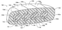
- FIG. 1is a cross-sectional view of a modular disc prosthesis according to the preferred embodiment of the present invention in its inserted configuration.
- FIG. 2is a top view of a modular disc prosthesis according to the preferred embodiment of the present invention prior to insertion.
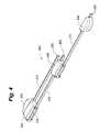
- FIG. 3is a perspective view of a modular disc prosthesis according to an alternate embodiment of the present invention prior to insertion.
- FIG. 4is a perspective view of a modular disc prosthesis according to an alternate embodiment of the present invention at a first stage of insertion.
- FIG. 5is a perspective a view of a modular disc prosthesis according to an alternate embodiment of the present invention at a second stage of insertion.
- FIG. 6is a perspective view of a modular disc prosthesis according to an alternate embodiment of the present invention at a final state of insertion.
- FIG. 7is a partial perspective view of a portion of a modular disc prosthesis according to an embodiment of the present invention.
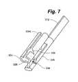
- FIG. 8is a view of an insertion tool for use in accordance with an embodiment of the present invention.
- FIG. 9Ais a perspective view of a modular disc prosthesis according to the preferred embodiment of the present invention.
- FIG. 9Bis a view of an inner portion of a modular segment of a modular disc prosthesis according to the preferred embodiment of the present invention.
- modular disc prosthesis 100comprises first 102 , second 104 , third 106 , fourth 108 , and fifth 109 modular segments.
- each modular segment 102 , 104 , 106 , 108 , 109comprises a soft outer portion 102 a , 104 a , 106 a , 108 a , 109 a and a hard inner portion 102 b , 104 b , 106 b , 108 b , 109 b.
- hard inner portions 104 b , 106 b and 108 bhave an I-beam cross-sectional shape that optimizes flexibility and strength of the hard inner portions.
- hard inner portions 104 b , 106 b , 108 bcan have a uniformly shaped cross-sectional area to reduce any differences in compressibility of the modular disc prosthesis 100 across the surface area in order to minimize the potential for stress risers to be created in the interface between the outer surface of the modular disc prosthesis 100 and the inner surfaces of the disc space cavity.
- Hard inner portion 102 b of first modular segment 102includes first segment interlocking portion 116 .
- Hard inner portion 104 b of second modular segment 104includes second segment interlocking portion 118 and a first slot 128 .
- Hard inner portion 106 b of third modular segment 106includes third segment interlocking portion 120 and a second slot 130 .
- Hard inner portion 108 b of fourth modular segment 108includes fourth segment interlocking portion 121 and a third slot 132 .
- Hard inner portion 109 b of fifth modular segment 109includes a fourth slot 133 .
- the inner portions 102 b , 104 b , 106 b , 108 b , and 109 bcan all be created from the same mold.
- the outer portions 102 a , 104 a , 106 a , 108 a , 109 a for modular segmentsare shown transparent for ease of explanation.
- the hard inner portions of the second 104 , third 106 , and fourth 108 modular segmentsare created from a uniform piece 130 , the shape of which is more clearly depicted in FIG. 9B .
- the inner portions for the first 102 b and fifth 109 b modular segmentscan each be easily created by grinding down a uniform inner portion 130 as depicted in FIG. 9B .
- Inner portion 102 b of first modular segment 102is created by grinding off the slot portion 132 of the uniform inner portion 130 and leaving the interlocking portion 134 and a connector portion 136 .
- Inner portion 109 b of fifth modular segment 109is created by grinding off the interlocking portion 134 and retaining the slot portion 132 and the connector portion 136 . This ability to form all of the hard inner portions from a single mold allows for quicker, simpler, and less expensive manufacturing.
- rails 110 , 112 , 114 , 115have a noncircular cross-sectional shape, although it will be understood that other cross-sectional shapes could be utilized and that there is no requirement that all of the rails have similar cross-sectional shapes. It has been found that the noncircular cross-sectional shape as shown (corresponding mating C and sideways T cross-sectional shapes) provides for better alignment of the modular segments and supports larger insertion forces along the axis of the rail.
- the rails 110 , 112 , 114 , 115 of the present inventionhave a non-uniform cross-sectional aspect ratio in terms of the height and width of the rail.
- the railshave a relative rigidity along a longitudinal axis of the rail in a dimension of the height of the rail that is greater than a width of the rail, whereas in a dimension transverse to the width of the rail the relative rigidity of the rail permits a greater degree of flexibility such that succeeding modular segments can be moved laterally with respect to one another in the expanded position without deforming the rails.
- the height of the railis in the range of about 1 mm to 6 mm and the width of the rail is in the range of about 0.5 mm to 4 mm.
- This differential rigidity in the two dimensions transverse to the longitudinal axis of the railis important in permitting effective and efficient sliding operation of the adjacent modular segments.
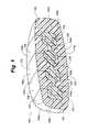
- FIG. 2there can be seen a portion of a modular disc prosthesis 100 according to the preferred embodiment of the present invention prior to insertion into the evacuated disc nucleus cavity.
- modular disc prosthesis 100is depicted showing only the hard inner portion 102 b , 104 b , 106 b , 108 b , 109 b of each modular segment 102 , 104 , 106 , 108 , 109 for convenience of illustration.
- each modular segmentwould also have a soft outer portion as described above and shown in FIG. 1 .
- the modular disc prosthesismay comprise greater or fewer numbers of modular segments and rails, as long as there are at least three modular segments and two rails.
- FIG. 3depicts a modular disc prosthesis 200 having four modular segments and three rails.
- modular disc prosthesis 100Prior to insertion, modular disc prosthesis 100 further includes first 110 , second 112 , third 114 , and fourth 115 rails.
- First modular segment 102is rigidly attached to first rail 110 at first segment interlocking portion 116 .
- Second modular segment 104is slidably attached to first rail 110 at first slot 128 and rigidly attached to second rail 112 at second segment interlocking portion 118 .
- Third modular segment 106is slidably attached to second rail 112 at second slot 130 and rigidly attached to third rail 114 at third segment interlocking portion 120 .
- Fourth modular segment 108is slidably attached to third rail 114 at third slot 132 and rigidly attached to fourth rail 115 at fourth segment interlocking portion 121 .
- Fifth modular segment 109is slidably attached to fourth rail 115 at fourth slot 133 .
- each rail 110 , 112 , 114 and 115 or 210 , 212 and 214includes a stem portion that extends beyond a periphery of the body of the prosthesis 100 , 200 , respectively.
- these stem portionsare long enough to permit access into the evacuated disc nucleus space such that one modular segment can be positioned inside the evacuated disc nucleus cavity while the next modular segment on the rail is still outside of the body.
- the length of the stem portionsranges between 6 cm-20 cm.
- each rail 210 , 212 , 214may further include a retaining portion 222 , 224 , 226 to keep the device from being separated prior to insertion.
- the retaining portions 222 , 224 and 226are configured to prevent the corresponding modular segments 204 , 206 and 206 from sliding off the rails.
- the retaining portionsmay be molded into the rails or may be separate pieces or deformations of the rails added during the manufacture of the device.
- the preferred embodimentis a unitary prosthesis that is packaged, sterile, and ready for implantation at the surgical site. Since the device is fully preformed and delivered as a unitary implant, the device is under direct surgeon control until the disc nucleus prosthesis is completely formed. This unitary design reduces the need for the surgeon to determine how to configure the prosthesis to allow for the most efficacious filling of the evacuated disc nucleus cavity and assures that the components' order of insertion and connection are properly achieved.
- the ability to predetermine the size of the modular disc prosthesisalso allows for the evacuated disc nucleus cavity to be more completely filled and provides a greater degree of control over the uniformity of the stress response of the implant as compared to other kinds of minimally invasive implants.
- the modular disc prosthesis 100 of the present inventionmay be provided in a variety of different final assembled volumes and shapes to correspond to different sizes and shapes of different evacuated disc nucleus cavities.
- Modular disc prosthesis 100may be introduced through an access tube that is inserted partially into the disc nucleus space.
- Access tubeis at least 3 inches long and preferably about 6 inches long.
- An insertion tool 400 as shown in FIG. 8may be used to aid in the insertion, positioning, and rail removal of the modular prosthesis.
- the proximal end of the tool 400has a handle 402 with an enclosed ratchet or roller mechanism attached to and in line with the inner lumen of an elongated tube 404 at the distal end of the tool through which a rail 406 may be inserted.
- the elongated tube 404may have a slit or other openings along the length of the tube 404 to aid in threading the rails 406 into the tube.
- Insertion tool 400can then be used to guide modular segments 408 into the disc space.
- the insertion tool 400may be made out of any combination of plastics, metals, ceramics, or the like.
- modular disc prosthesis 100is described in relation to a preferred five-segment embodiment or an alternate four-segment embodiment, embodiments having any other number of segments would be inserted in a similar fashion.
- a modular disc prosthesis 200prior to insertion into the body.
- the first rail 210is threaded through the lumen of the elongated tube 404 of the insertion tool 400 .
- the insertion tool 400is then used to push first modular segment 202 through the tube and into the disc space.
- modular disc prosthesis 200is moved centrally and the insertion tool 400 is repositioned onto the first rail 210 proximal to second modular segment 204 which is slid along the first rail 210 into the evacuated disc nucleus space onto first segment interlocking portion 216 until it is flush with first modular segment 202 .
- This stage of insertionis depicted in FIG. 4 .
- a stem portion of first rail 210is then removed and modular disc prosthesis 200 is moved centrally again.
- Second rail 212is then threaded through insertion tool 400 and third modular segment 206 is slid down second rail 212 and into the disc nucleus space onto second segment interlocking portion 218 until it is flush with second modular segment 204 .
- This configurationis shown in FIG. 5 .
- a stem portion of second rail 212is then removed and modular disc prosthesis 200 is moved centrally.
- Third rail 214is then threaded through insertion tool and fourth modular segment 208 is slid along third rail 214 into the disc nucleus space and onto third segment interlocking portion 220 until it is flush with the other modular segments 202 , 204 , 206 .
- a stem portion of third rail 214is removed.
- Modular disc prosthesis 200is sized and shaped to conform to the geometry of the evacuated disc nucleus cavity.
- a keystone approachcan be used to insert the modular disc prosthesis such that the last modular segment inserted into the disc nucleus space is not one of the outside segments. Instead, the outside segments can be the first two segments inserted. This creates a bilateral expansion force as the remaining segments are inserted between the two outside segments. This helps make a tighter fit within the evacuated disc nucleus cavity than does the asymmetric lateral force imparted when the segments are implanted sequentially.
- Insertion tool 400may be provided with a cutting mechanism that can remove the stem portions of the rails.
- the cutting mechanismmay be a pair of fixed blades located on the distal end of the pushing tool. In this embodiment, the cutting blades would act as a cutting wheel in which a turning of the handle connected to the blades causes the blades to circumscribe the rail.
- the cutting mechanismcan be a clamping means that removes the rails through twisting or pinching. Stem rails may also be cut off with any other sharp instrument.
- the stem portions of the railsmay be provided with a perforation at the junction with each modular segment such that they can be torn, broken, twisted, or more easily cut off. Cutting may also be accomplished with a wire loop provided to the part. Additionally, heat, laser, or any other local energy source can be used to accomplish the separation.
- the modular disc prosthesismay be implanted using an anterior lateral approach.
- An anterior lateral approachallows for a larger insertion opening to be used while still being minimally invasive.
- the discis accessed from the patient's side through the psoas muscle, which avoids major nerve and vascular tissues, and may be used in the presence of medical conditions mitigating against the posterior approach.
- This approachis essentially oriented 90° from the posterior approach.
- slots 128 , 130 , 132 , 133slide along the stem portions of rails 110 , 112 , 114 , 115 and onto segment interlocking portions 116 , 118 , 120 , 121 .
- Slots 128 , 130 , 132 , 133 and segment interlocking portions 116 , 118 , 120 , 121may be provided with locking features to prevent separation of modular segments 102 , 104 , 106 , 108 , 109 .
- Locking featuressuch as a barb or stud or a series of barbs or studs, may be provided such that once a slot is slid onto a segment interlocking portion, it cannot be slid back off of it.
- a ratchet and pawlmay also be used to lock modular segments together.
- a ratchet release toolmay also be provided in case separation of modular segments is desired once they are locked together.
- Hard inner portion 304 b of each modular segment 304is provided with a pair of depressible projections 334 on segment interlocking portion 318 and a complementary pair of apertures 336 on slot 328 .
- projectionsare depressed.
- apertures of the first modular segmentare positioned over projections of the second modular segment, the projections pop through apertures 336 , locking the modular segments relative to one another.
- Modular segmentsmay be separated by depressing the projections and sliding the first modular segment back off of the second modular segment.
- modular disc prosthesis 100is molded from elastomeric biomaterials, preferably polyurethane.
- Stem rails 110 , 112 , 114 , 115 and hard inner portions 102 b , 104 b , 106 b , 108 b , 109 bare made from a hard durometer polyurethane, such as a polyurethane with a Shore D hardness of about 45 or above and compressive modulus in the range of about 70 to 100 MPa.
- Soft outer portions 102 a , 104 a , 106 a , 108 a , 109 aare made from a softer durometer polyurethane, such as a polyurethane with a Shore A hardness ranging from about 40 to 80 and a compressive modulus in the range of about 6 to 20 MPa.
- the two different durometer polyurethanesmay be co-polymerized to create a chemical bond between the two portions of each modular segment 102 , 104 , 106 , 108 , 109 .
- other polymerssuch as PEEK, polyethylene, silicones, acrylates, nylon, polyacetyls, and other similar biocompatible polymers may be used for the hard inner portions or the soft outer portions.
- the stem of the tailsmay be molded from a harder durometer material than soft outer portion and hard inner portion of modular segments. Utilizing this approach allows the rails to be extruded, rather than molded as part of the modular segments. A bond joint can then be made with the hard inner portion external to the periphery of the modular segments to form the unitary design. Extruding the stem portions of the tails makes the modular disc prosthesis easier and less expensive to manufacture than a completely molded product.
- the modular disc prosthesisis deformable in response to normal physiological forces of 30 to 300 pounds. Because of this deformability, the prosthesis produces a physiologically appropriate amount of loading on the end plates of the intervertebral disc. As a result, the end plates will not excessively deform over time and ultimately conform to the contours of the implant as is the case with many more rigid disc nucleus replacement implants.
- the outer shell of the modular disc nucleus prosthesismay be modified to provide for elution of medicants.
- medicantsmay include analgesics, antibiotics, antineoplastics or bioosteologics such as bone growth agents. While motion preservation is generally a principle goal in nucleus replacement, in certain indications it may be desirable to promote some bony fusion. Such indications may include nucleus replacements in the cervical spine.
- the solid polymer outer shell of the modular disc nucleus prosthesismay provide for better and more controllable elution rates than some hydrogel materials.
- the modular disc nucleus prosthesismay include different elution rates for each polymer material. This would allow for varying elution rates for different medicants.
Landscapes
- Health & Medical Sciences (AREA)
- Engineering & Computer Science (AREA)
- Biomedical Technology (AREA)
- Orthopedic Medicine & Surgery (AREA)
- Transplantation (AREA)
- Neurology (AREA)
- Heart & Thoracic Surgery (AREA)
- Oral & Maxillofacial Surgery (AREA)
- Cardiology (AREA)
- Vascular Medicine (AREA)
- Life Sciences & Earth Sciences (AREA)
- Animal Behavior & Ethology (AREA)
- General Health & Medical Sciences (AREA)
- Public Health (AREA)
- Veterinary Medicine (AREA)
- Physical Education & Sports Medicine (AREA)
- Prostheses (AREA)
- Materials For Medical Uses (AREA)
Abstract
Description
Claims (6)
Priority Applications (20)
| Application Number | Priority Date | Filing Date | Title |
|---|---|---|---|
| US11/372,477US7591853B2 (en) | 2005-03-09 | 2006-03-09 | Rail-based modular disc nucleus prosthesis |
| EP06771111.9AEP1883378B1 (en) | 2005-05-24 | 2006-05-24 | Rail-based modular disc nucleus prosthesis |
| HK08111702.8AHK1116041B (en) | 2005-05-24 | 2006-05-24 | Interlocked modular disc nucleus prosthesis |
| EP06760355AEP1887986A4 (en) | 2005-05-24 | 2006-05-24 | Interlocked modular disc nucleus prosthesis |
| PCT/US2006/020152WO2006127849A2 (en) | 2005-05-24 | 2006-05-24 | Rail-based modular disc nucleus prosthesis |
| KR1020077029964AKR101328801B1 (en) | 2005-05-24 | 2006-05-24 | Interlocked modular disc nucleus prosthesis |
| HK10101206.6AHK1134010B (en) | 2005-05-24 | 2006-05-24 | Rail-based modular disc nucleus prosthesis |
| PCT/US2006/020150WO2006127848A2 (en) | 2005-03-09 | 2006-05-24 | Interlocked modular disc nucleus prosthesis |
| BRPI0611200-5ABRPI0611200A2 (en) | 2005-05-24 | 2006-05-24 | rail-based modular disk core prosthesis |
| JP2008513686AJP4832514B2 (en) | 2005-05-24 | 2006-05-24 | Interlocking modular disc nucleus prosthesis |
| CN2006800184530ACN101500513B (en) | 2005-05-24 | 2006-05-24 | Rail-Based Modular Disc Nucleus Prosthesis |
| KR1020077029963AKR101330340B1 (en) | 2005-05-24 | 2006-05-24 | Rail-based modular disc nucleus prosthesis |
| JP2008513687AJP4891991B2 (en) | 2005-05-24 | 2006-05-24 | Rail-based modular disc nucleus pulposus prosthesis |
| BRPI0611201-3ABRPI0611201A2 (en) | 2005-05-24 | 2006-05-24 | embedded disc core modular prosthesis |
| CN200680018462XACN101193608B (en) | 2005-05-24 | 2006-05-24 | Interlocked modular disc nucleus prosthesis |
| EP06774673AEP1906886A4 (en) | 2005-07-19 | 2006-07-19 | Multi-composite disc prosthesis |
| PCT/US2006/028020WO2007012003A2 (en) | 2005-03-09 | 2006-07-19 | Multi-composite disc prosthesis |
| US11/489,264US8038718B2 (en) | 2005-03-09 | 2006-07-19 | Multi-composite disc prosthesis |
| US12/435,087US20090276047A1 (en) | 2005-03-09 | 2009-05-04 | Rail-based modular disc prosthesis |
| US12/548,225US20100057144A1 (en) | 2005-03-09 | 2009-08-26 | Rail-based modular disc nucleus prosthesis |
Applications Claiming Priority (4)
| Application Number | Priority Date | Filing Date | Title |
|---|---|---|---|
| US66010705P | 2005-03-09 | 2005-03-09 | |
| US68533205P | 2005-05-24 | 2005-05-24 | |
| US70045905P | 2005-07-19 | 2005-07-19 | |
| US11/372,477US7591853B2 (en) | 2005-03-09 | 2006-03-09 | Rail-based modular disc nucleus prosthesis |
Related Child Applications (2)
| Application Number | Title | Priority Date | Filing Date |
|---|---|---|---|
| US12/435,087ContinuationUS20090276047A1 (en) | 2005-03-09 | 2009-05-04 | Rail-based modular disc prosthesis |
| US12/548,225DivisionUS20100057144A1 (en) | 2005-03-09 | 2009-08-26 | Rail-based modular disc nucleus prosthesis |
Publications (2)
| Publication Number | Publication Date |
|---|---|
| US20070050036A1 US20070050036A1 (en) | 2007-03-01 |
| US7591853B2true US7591853B2 (en) | 2009-09-22 |
Family
ID=46062833
Family Applications (7)
| Application Number | Title | Priority Date | Filing Date |
|---|---|---|---|
| US11/372,357ActiveUS7267690B2 (en) | 2005-03-09 | 2006-03-09 | Interlocked modular disc nucleus prosthesis |
| US11/372,477ActiveUS7591853B2 (en) | 2005-03-09 | 2006-03-09 | Rail-based modular disc nucleus prosthesis |
| US11/489,264Active2026-11-09US8038718B2 (en) | 2005-03-09 | 2006-07-19 | Multi-composite disc prosthesis |
| US11/900,205Active2027-10-29US8100977B2 (en) | 2005-03-09 | 2007-09-10 | Interlocked modular disc nucleus prosthesis |
| US11/900,209AbandonedUS20080208343A1 (en) | 2005-03-09 | 2007-09-10 | Interlocked modular disc nucleus prosthesis |
| US12/435,087AbandonedUS20090276047A1 (en) | 2005-03-09 | 2009-05-04 | Rail-based modular disc prosthesis |
| US12/548,225AbandonedUS20100057144A1 (en) | 2005-03-09 | 2009-08-26 | Rail-based modular disc nucleus prosthesis |
Family Applications Before (1)
| Application Number | Title | Priority Date | Filing Date |
|---|---|---|---|
| US11/372,357ActiveUS7267690B2 (en) | 2005-03-09 | 2006-03-09 | Interlocked modular disc nucleus prosthesis |
Family Applications After (5)
| Application Number | Title | Priority Date | Filing Date |
|---|---|---|---|
| US11/489,264Active2026-11-09US8038718B2 (en) | 2005-03-09 | 2006-07-19 | Multi-composite disc prosthesis |
| US11/900,205Active2027-10-29US8100977B2 (en) | 2005-03-09 | 2007-09-10 | Interlocked modular disc nucleus prosthesis |
| US11/900,209AbandonedUS20080208343A1 (en) | 2005-03-09 | 2007-09-10 | Interlocked modular disc nucleus prosthesis |
| US12/435,087AbandonedUS20090276047A1 (en) | 2005-03-09 | 2009-05-04 | Rail-based modular disc prosthesis |
| US12/548,225AbandonedUS20100057144A1 (en) | 2005-03-09 | 2009-08-26 | Rail-based modular disc nucleus prosthesis |
Country Status (2)
| Country | Link |
|---|---|
| US (7) | US7267690B2 (en) |
| WO (2) | WO2006127848A2 (en) |
Cited By (20)
| Publication number | Priority date | Publication date | Assignee | Title |
|---|---|---|---|---|
| US20070233244A1 (en)* | 2006-03-28 | 2007-10-04 | Depuy Spine, Inc. | Artificial Disc Replacement Using Posterior Approach |
| US20070233261A1 (en)* | 2006-03-28 | 2007-10-04 | Depuy Spine, Inc. | Artificial Disc Replacement Using Posterior Approach |
| US20080009944A1 (en)* | 2001-10-02 | 2008-01-10 | Rex Medical | Spinal implant and method of use |
| US20080051897A1 (en)* | 2006-03-28 | 2008-02-28 | Depuy Spine, Inc. | Methods and instrumentation for disc replacement |
| US20080133012A1 (en)* | 2006-11-16 | 2008-06-05 | Mcguckin James F | Spinal implant and method of use |
| US20080234820A1 (en)* | 2000-08-28 | 2008-09-25 | Felt Jeffrey C | Method and system for mammalian joint resurfacing |
| US20080249622A1 (en)* | 2007-04-05 | 2008-10-09 | Gray Wayne P | Interbody implant |
| US20080312743A1 (en)* | 2007-06-15 | 2008-12-18 | Thierry Vila | Nucleus Prostheses |
| US20090192614A1 (en)* | 2008-01-25 | 2009-07-30 | Aesculap Ag | Intervertebral implant |
| US8038718B2 (en) | 2005-03-09 | 2011-10-18 | Vertebral Technologies, Inc. | Multi-composite disc prosthesis |
| WO2013138803A1 (en) | 2012-03-16 | 2013-09-19 | Vertebral Technologies, Inc. | A modular segmented disc nucleus implant |
| US8795375B2 (en) | 2008-07-23 | 2014-08-05 | Resspond Spinal Systems | Modular nucleus pulposus prosthesis |
| US9314348B2 (en) | 2014-06-04 | 2016-04-19 | Wenzel Spine, Inc. | Bilaterally expanding intervertebral body fusion device |
| US9358122B2 (en) | 2011-01-07 | 2016-06-07 | K2M, Inc. | Interbody spacer |
| US9364338B2 (en) | 2008-07-23 | 2016-06-14 | Resspond Spinal Systems | Modular nucleus pulposus prosthesis |
| US9737414B2 (en) | 2006-11-21 | 2017-08-22 | Vertebral Technologies, Inc. | Methods and apparatus for minimally invasive modular interbody fusion devices |
| US9795492B1 (en)* | 2012-04-30 | 2017-10-24 | Nuvasive, Inc. | Magnetically connectable interbody spinal implant devices |
| US20210128314A1 (en)* | 2007-12-28 | 2021-05-06 | Nuvasive, Inc. | Spinal Surgical Implant and Related Methods |
| US11219531B2 (en) | 2019-04-10 | 2022-01-11 | Wenzel Spine, Inc. | Rotatable intervertebral spacing implant |
| US11304737B1 (en)* | 2020-11-19 | 2022-04-19 | Design Enterprises, Llc | Placement jigs for osteosynthesis systems and related methods |
Families Citing this family (57)
| Publication number | Priority date | Publication date | Assignee | Title |
|---|---|---|---|---|
| CA2359816C (en)* | 1999-01-06 | 2010-08-03 | Genenews Inc. | Method for the detection of gene transcripts in blood and uses thereof |
| WO2006066228A2 (en)* | 2004-12-16 | 2006-06-22 | Innovative Spinal Technologies | Expandable implants for spinal disc replacement |
| AU2006203906A1 (en)* | 2005-01-08 | 2006-07-13 | Alphaspine, Inc. | Modular disc device |
| US20060265077A1 (en)* | 2005-02-23 | 2006-11-23 | Zwirkoski Paul A | Spinal repair |
| US20070173941A1 (en)* | 2006-01-25 | 2007-07-26 | Sdgi Holdings, Inc. | Intervertebral prosthetic disc and method of installing same |
| US7615079B2 (en)* | 2006-04-20 | 2009-11-10 | Meditech Advisors, Llc | Monorail system |
| US8790403B2 (en)* | 2006-04-20 | 2014-07-29 | K2M, Inc. | Monorail system |
| US20070260318A1 (en)* | 2006-05-03 | 2007-11-08 | Lawson Kevin J | Modular disc for spinal arthroplasty through a small posterior exposure with intradiscalor intervertebral assembly in-situ |
| US20080039942A1 (en)* | 2006-08-11 | 2008-02-14 | Bergeron Brian J | Spinal implant |
| US8506636B2 (en) | 2006-09-08 | 2013-08-13 | Theken Spine, Llc | Offset radius lordosis |
| US20100191333A1 (en)* | 2007-06-08 | 2010-07-29 | Morrison Iii Thomas J | Load-bearing spinal interbody device |
| US8685099B2 (en)* | 2007-08-14 | 2014-04-01 | Warsaw Orthopedic, Inc. | Multiple component osteoimplant |
| US7972380B2 (en)* | 2007-09-17 | 2011-07-05 | Linares Medical Devices, Llc | Artificial joint support between first and second bones |
| US20090299479A1 (en)* | 2007-10-19 | 2009-12-03 | Jones Robert J | Suture guided implant |
| US7967866B2 (en)* | 2007-11-27 | 2011-06-28 | Warsaw Orthopedic, Inc. | Stackable intervertebral devices and methods of use |
| US8613773B2 (en)* | 2007-12-05 | 2013-12-24 | Spinal U.S.A. | Disc nucleus replacement |
| US7985231B2 (en) | 2007-12-31 | 2011-07-26 | Kyphon Sarl | Bone fusion device and methods |
| US7799056B2 (en) | 2007-12-31 | 2010-09-21 | Warsaw Orthopedic, Inc. | Bone fusion device and methods |
| MX2010008003A (en)* | 2008-01-29 | 2010-09-24 | Milux Holding Sa | Apparatus for treating obesity. |
| US8518113B2 (en)* | 2008-05-20 | 2013-08-27 | Warsaw Othopedic, Inc. | Intervertebral implant and methods of implantation and manufacture |
| US20100063592A1 (en)* | 2008-09-05 | 2010-03-11 | James William Dwyer | Interlocking multi-piece intervertebral disc prosthesis and method for implanting same |
| US8814937B2 (en) | 2008-09-18 | 2014-08-26 | Peter L. Mayer | Intervertebral disc prosthesis, method for assembling, method for implanting prosthesis, and method for explanting |
| US8187333B2 (en)* | 2008-09-18 | 2012-05-29 | Mayer Peter L | Intervertebral disc prosthesis and method for implanting and explanting |
| US9636121B2 (en)* | 2008-11-11 | 2017-05-02 | Harbinger Medical Group, Llc | Facet distraction device, facet joint implant, and associated methods |
| EP2379017A4 (en)* | 2009-01-21 | 2013-06-19 | Warsaw Orthopedic Inc | Spinal nucleus replacement implants |
| US8292962B2 (en)* | 2009-03-04 | 2012-10-23 | Warsaw Orthopedic, Inc. | Spinal nucleus replacement implants |
| CN102448379B (en) | 2009-04-03 | 2014-11-19 | 米切尔·A·哈登布鲁克 | Surgical retractor system |
| US9132207B2 (en) | 2009-10-27 | 2015-09-15 | Spine Wave, Inc. | Radiopaque injectable nucleus hydrogel compositions |
| US8840668B1 (en) | 2009-11-11 | 2014-09-23 | Nuvasive, Inc. | Spinal implants, instruments and related methods |
| US8740983B1 (en) | 2009-11-11 | 2014-06-03 | Nuvasive, Inc. | Spinal fusion implants and related methods |
| US20110218627A1 (en)* | 2010-03-03 | 2011-09-08 | Warsaw Orthopedic, Inc. | System and method for replacing at least a portion of a vertebral body |
| EP2675398A4 (en)* | 2011-02-15 | 2017-01-25 | Omni Life Science, Inc. | Modular prosthesis |
| US9700425B1 (en) | 2011-03-20 | 2017-07-11 | Nuvasive, Inc. | Vertebral body replacement and insertion methods |
| FR2974497A1 (en)* | 2011-04-27 | 2012-11-02 | Centre Nat Rech Scient | INTERVERTEBRAL DISC PROSTHESIS IN THERMOPLASTIC MATERIAL WITH A GRADIENT OF MECHANICAL PROPERTIES |
| US9277946B2 (en) | 2011-09-06 | 2016-03-08 | Amendia, Inc. | Spinal fusion system |
| US9848994B2 (en)* | 2011-09-16 | 2017-12-26 | Globus Medical, Inc. | Low profile plate |
| US9198765B1 (en) | 2011-10-31 | 2015-12-01 | Nuvasive, Inc. | Expandable spinal fusion implants and related methods |
| US9468536B1 (en) | 2011-11-02 | 2016-10-18 | Nuvasive, Inc. | Spinal fusion implants and related methods |
| US8795167B2 (en) | 2011-11-15 | 2014-08-05 | Baxano Surgical, Inc. | Spinal therapy lateral approach access instruments |
| US8764757B1 (en)* | 2012-01-31 | 2014-07-01 | Luis M. Tumialan | MIS TLIF systems and related methods |
| US9125753B2 (en) | 2012-02-17 | 2015-09-08 | Ervin Caballes | Elastomeric artificial joints and intervertebral prosthesis systems |
| US9393126B2 (en) | 2012-04-20 | 2016-07-19 | Peter L. Mayer | Bilaterally placed disc prosthesis for spinal implant and method of bilateral placement |
| US9364339B2 (en) | 2012-04-30 | 2016-06-14 | Peter L. Mayer | Unilaterally placed expansile spinal prosthesis |
| EP2877129B1 (en) | 2012-07-25 | 2017-10-11 | Spineology, Inc. | Mesh spacer hybrid |
| US9278011B2 (en)* | 2012-08-08 | 2016-03-08 | Spectrum Spine Ip Holdings, Llc | Percutaneous cage delivery systems devices and methods |
| WO2014033651A1 (en)* | 2012-08-29 | 2014-03-06 | Nlt Spine Ltd | Method and system for implants |
| US9445918B1 (en) | 2012-10-22 | 2016-09-20 | Nuvasive, Inc. | Expandable spinal fusion implants and related instruments and methods |
| USD731061S1 (en) | 2012-11-28 | 2015-06-02 | Nuvasive, Inc. | Intervertebral implant |
| USD745159S1 (en) | 2013-10-10 | 2015-12-08 | Nuvasive, Inc. | Intervertebral implant |
| US9782270B2 (en)* | 2014-08-08 | 2017-10-10 | Warsaw Orthopedic, Inc. | Spinal implant system and method |
| USD858769S1 (en) | 2014-11-20 | 2019-09-03 | Nuvasive, Inc. | Intervertebral implant |
| CA2917676A1 (en)* | 2015-01-13 | 2016-07-13 | Stryker European Holdings I, Llc | Growing rods and methods of use |
| EP3048345A1 (en) | 2015-01-21 | 2016-07-27 | Anheuser-Busch InBev S.A. | Stopcock for beverage dispenser |
| US10080665B2 (en)* | 2015-06-05 | 2018-09-25 | Hoan Phan Tran | Devices and approach for prone intervertebral implant |
| US11446064B2 (en) | 2018-04-26 | 2022-09-20 | Stryker European Operations Holdings Llc | Orthopedic growing devices |
| JP6700511B1 (en)* | 2019-08-30 | 2020-05-27 | リーガエース株式会社 | System for guiding interbody spacers between bodies |
| CN111616844A (en)* | 2020-06-30 | 2020-09-04 | 杨晋才 | A minimally invasive open fusion device |
Citations (43)
| Publication number | Priority date | Publication date | Assignee | Title |
|---|---|---|---|---|
| US4772287A (en) | 1987-08-20 | 1988-09-20 | Cedar Surgical, Inc. | Prosthetic disc and method of implanting |
| US4911718A (en) | 1988-06-10 | 1990-03-27 | University Of Medicine & Dentistry Of N.J. | Functional and biocompatible intervertebral disc spacer |
| US5192326A (en) | 1990-12-21 | 1993-03-09 | Pfizer Hospital Products Group, Inc. | Hydrogel bead intervertebral disc nucleus |
| US5458643A (en) | 1991-03-29 | 1995-10-17 | Kyocera Corporation | Artificial intervertebral disc |
| US5545229A (en)* | 1988-08-18 | 1996-08-13 | University Of Medicine And Dentistry Of Nj | Functional and biocompatible intervertebral disc spacer containing elastomeric material of varying hardness |
| US5609635A (en) | 1988-06-28 | 1997-03-11 | Michelson; Gary K. | Lordotic interbody spinal fusion implants |
| US5702454A (en) | 1993-04-21 | 1997-12-30 | Sulzer Orthopadie Ag | Process for implanting an invertebral prosthesis |
| US5772661A (en) | 1988-06-13 | 1998-06-30 | Michelson; Gary Karlin | Methods and instrumentation for the surgical correction of human thoracic and lumbar spinal disease from the antero-lateral aspect of the spine |
| US5776199A (en) | 1988-06-28 | 1998-07-07 | Sofamor Danek Properties | Artificial spinal fusion implants |
| US5860973A (en) | 1995-02-27 | 1999-01-19 | Michelson; Gary Karlin | Translateral spinal implant |
| US5919236A (en) | 1996-08-24 | 1999-07-06 | Cerasiv Gmbh - Innovatives Keramik Engineering | Joint prosthesis |
| US6096038A (en) | 1988-06-13 | 2000-08-01 | Michelson; Gary Karlin | Apparatus for inserting spinal implants |
| US6110210A (en) | 1999-04-08 | 2000-08-29 | Raymedica, Inc. | Prosthetic spinal disc nucleus having selectively coupled bodies |
| US20020026244A1 (en) | 2000-08-30 | 2002-02-28 | Trieu Hai H. | Intervertebral disc nucleus implants and methods |
| US6387130B1 (en) | 1999-04-16 | 2002-05-14 | Nuvasive, Inc. | Segmented linked intervertebral implant systems |
| US6443988B2 (en) | 1994-05-06 | 2002-09-03 | Disc Dynamics, Inc. | Mold apparatus and kit for in situ tissue repair |
| US6468311B2 (en) | 2001-01-22 | 2002-10-22 | Sdgi Holdings, Inc. | Modular interbody fusion implant |
| US6533818B1 (en) | 2000-04-26 | 2003-03-18 | Pearl Technology Holdings, Llc | Artificial spinal disc |
| US20030055506A1 (en) | 1999-09-30 | 2003-03-20 | Stoy Vladimir A. | Hydrogel-based prosthetic device for replaceing at least a part of the nucleus of a spinal disc |
| US6595998B2 (en)* | 2001-03-08 | 2003-07-22 | Spinewave, Inc. | Tissue distraction device |
| US6652587B2 (en)* | 2000-08-28 | 2003-11-25 | Advanced Bio Surfaces, Inc. | Method and system for mammalian joint resurfacing |
| US20040054413A1 (en) | 2002-09-16 | 2004-03-18 | Howmedica Osteonics Corp. | Radiovisible hydrogel intervertebral disc nucleus |
| US6740093B2 (en) | 2000-02-28 | 2004-05-25 | Stephen Hochschuler | Method and apparatus for treating a vertebral body |
| US20040186576A1 (en) | 2003-03-20 | 2004-09-23 | Spineco, Inc., An Ohio Corporation | Expandable spherical spinal implant |
| US20040220672A1 (en)* | 2003-05-03 | 2004-11-04 | Shadduck John H. | Orthopedic implants, methods of use and methods of fabrication |
| US20050010290A1 (en)* | 2003-06-26 | 2005-01-13 | Hawkins John R. | Dual durometer elastomer artificial disc |
| US20050015150A1 (en) | 2003-07-17 | 2005-01-20 | Lee Casey K. | Intervertebral disk and nucleus prosthesis |
| US20050055097A1 (en) | 2001-12-31 | 2005-03-10 | Expandis Ltd. An Israeli Corporation | Minimally invasive modular support implant device and method |
| US20050154465A1 (en) | 2004-01-09 | 2005-07-14 | Sdgi Holdings, Inc. | Split spinal device and method |
| US20050203599A1 (en)* | 2004-03-12 | 2005-09-15 | Scimed Life Systems, Inc. | Modular stimulation lead network |
| US20050273178A1 (en)* | 2004-02-06 | 2005-12-08 | Boyan Barbara D | Load bearing biocompatible device |
| US20060106462A1 (en) | 2002-04-16 | 2006-05-18 | Tsou Paul M | Implant material for minimally invasive spinal interbody fusion surgery |
| US20060167550A1 (en)* | 2002-10-08 | 2006-07-27 | Robert Snell | High precision manufacture of polyurethane products such as spinal disc implants having a gradual modulus variation |
| US20060189999A1 (en) | 2005-02-24 | 2006-08-24 | Paul Zwirkoski | Linked slideable and interlockable rotatable components |
| US20060195191A1 (en)* | 2005-01-08 | 2006-08-31 | Alphaspine Inc. | Modular disc device |
| US20060247778A1 (en)* | 2005-01-26 | 2006-11-02 | Ferree Bret A | Intradiscal devices including spacers facilitating posterior-lateral and other insertion approaches |
| US20060259144A1 (en)* | 2004-01-27 | 2006-11-16 | Warsaw Orthopedic Inc. | Hybrid intervertebral disc system |
| US20060293756A1 (en) | 2005-03-09 | 2006-12-28 | Felt Jeffrey C | Interlocked modular nucleus prosthesis |
| US20070032874A1 (en)* | 2005-01-19 | 2007-02-08 | Nexgen Spine, Inc. | Elastomeric intervertebral disc prosthesis |
| US20070244485A1 (en) | 2004-09-21 | 2007-10-18 | Greenhalgh E S | Expandable support device and method of use |
| US20080065220A1 (en)* | 2003-05-02 | 2008-03-13 | Neville Alleyne | Artificial spinal disk |
| US20080119853A1 (en) | 2006-11-21 | 2008-05-22 | Jeffrey Felt | Methods and apparatus for minimally invasive modular interbody fusion devices |
| US20080133017A1 (en)* | 2004-11-15 | 2008-06-05 | Disc-O- Tech Medical Technology | Assembled Prosthesis Such as a Disc |
Family Cites Families (176)
| Publication number | Priority date | Publication date | Assignee | Title |
|---|---|---|---|---|
| US582803A (en)* | 1897-05-18 | Coupling for vehicle-poles | ||
| US3030951A (en)* | 1959-04-10 | 1962-04-24 | Michael P Mandarino | Methods and materials for orthopedic surgery |
| SE391122B (en) | 1971-01-25 | 1977-02-07 | Cutter Lab | PROTESTS IN THE FORM OF A SPINE BONIC DISC AND PROCEDURES FOR MANUFACTURE THEREOF |
| US3728742A (en)* | 1971-06-18 | 1973-04-24 | Howmedica | Knee or elbow prosthesis |
| US3848601A (en) | 1972-06-14 | 1974-11-19 | G Ma | Method for interbody fusion of the spine |
| US3815599A (en) | 1973-03-02 | 1974-06-11 | W Deyerle | Femoral shaft surgical rasp for use in hip prosthesis surgery |
| US3867729A (en)* | 1973-08-17 | 1975-02-25 | Mere Ind Inc | Incinerator |
| US4081866A (en)* | 1977-02-02 | 1978-04-04 | Howmedica, Inc. | Total anatomical knee prosthesis |
| US4203444A (en)* | 1977-11-07 | 1980-05-20 | Dyonics, Inc. | Surgical instrument suitable for closed surgery such as of the knee |
| CA1146301A (en) | 1980-06-13 | 1983-05-17 | J. David Kuntz | Intervertebral disc prosthesis |
| US4502161A (en)* | 1981-09-21 | 1985-03-05 | Wall W H | Prosthetic meniscus for the repair of joints |
| US4476293A (en) | 1981-11-30 | 1984-10-09 | E. I. Du Pont De Nemours And Company | Polymeric carbonate diols of copolyether glycols and polyurethanes prepared therefrom |
| US4463141A (en) | 1981-11-30 | 1984-07-31 | E. I. Du Pont De Nemours And Company | Polyether carbonate diols and polyurethanes prepared therefrom |
| US4456745A (en) | 1982-05-24 | 1984-06-26 | Ethyl Corporation | Polyurethanes prepared from polycarbonates |
| US4477604A (en) | 1982-09-20 | 1984-10-16 | Oechsle Iii Sixtus J | Polyurethane compositions and their use as luting agents |
| DE3318730A1 (en)* | 1983-05-21 | 1984-11-22 | Akzo Gmbh, 5600 Wuppertal | Biocompatible polyurethanes |
| US4722948A (en)* | 1984-03-16 | 1988-02-02 | Dynatech Corporation | Bone replacement and repair putty material from unsaturated polyester resin and vinyl pyrrolidone |
| DE3433264C2 (en) | 1984-09-11 | 1986-10-02 | S + G Implants GmbH, 2400 Lübeck | Tibial part for a knee joint endoprosthesis |
| US4743256A (en)* | 1985-10-04 | 1988-05-10 | Brantigan John W | Surgical prosthetic implant facilitating vertebral interbody fusion and method |
| US4647643A (en)* | 1985-11-08 | 1987-03-03 | Becton, Dickinson And Company | Soft non-blocking polyurethanes |
| US4651736A (en)* | 1986-02-01 | 1987-03-24 | Bruce Sanders | Methods for temporomandibular joint small incision surgery |
| GB8620937D0 (en) | 1986-08-29 | 1986-10-08 | Shepperd J A N | Spinal implant |
| US4834757A (en)* | 1987-01-22 | 1989-05-30 | Brantigan John W | Prosthetic implant |
| US4743632A (en)* | 1987-02-25 | 1988-05-10 | Pfizer Hospital Products Group, Inc. | Polyetherurethane urea polymers as space filling tissue adhesives |
| DE3717060A1 (en)* | 1987-05-21 | 1988-12-01 | Bayer Ag | POLYETHER-POLYCARBONATE-DIOLE, THEIR PRODUCTION AND USE AS STARTING PRODUCTS FOR POLYURETHANE PLASTICS |
| US5306311A (en)* | 1987-07-20 | 1994-04-26 | Regen Corporation | Prosthetic articular cartilage |
| US4880610A (en) | 1988-04-20 | 1989-11-14 | Norian Corporation | In situ calcium phosphate minerals--method and composition |
| US4873308A (en) | 1988-09-30 | 1989-10-10 | Medtronic, Inc. | Biostable, segmented aliphatic polyurethanes and process therefor |
| US4938763B1 (en)* | 1988-10-03 | 1995-07-04 | Atrix Lab Inc | Biodegradable in-situ forming implants and method of producing the same |
| FR2639823A1 (en) | 1988-12-06 | 1990-06-08 | Garcia Alain | Replacement of the nucleus of the intervertebral disc by a polyurethane polymerised in situ |
| US4872452A (en) | 1989-01-09 | 1989-10-10 | Minnesota Mining And Manufacturing Company | Bone rasp |
| US4969888A (en) | 1989-02-09 | 1990-11-13 | Arie Scholten | Surgical protocol for fixation of osteoporotic bone using inflatable device |
| US5007940A (en)* | 1989-06-09 | 1991-04-16 | American Medical Systems, Inc. | Injectable polymeric bodies |
| US5263987A (en) | 1989-08-25 | 1993-11-23 | Shah Mrugesh K | Method and apparatus for arthroscopically replacing a bone joint |
| DE4029969A1 (en)* | 1989-09-21 | 1991-04-04 | Asahi Optical Co Ltd | METHOD FOR PRODUCING BONE PROSTHESES |
| US5067964A (en) | 1989-12-13 | 1991-11-26 | Stryker Corporation | Articular surface repair |
| US5254662A (en) | 1990-09-12 | 1993-10-19 | Polymedia Industries, Inc. | Biostable polyurethane products |
| US5047055A (en) | 1990-12-21 | 1991-09-10 | Pfizer Hospital Products Group, Inc. | Hydrogel intervertebral disc nucleus |
| US5192327A (en)* | 1991-03-22 | 1993-03-09 | Brantigan John W | Surgical prosthetic implant for vertebrae |
| NL9101159A (en) | 1991-07-03 | 1993-02-01 | Industrial Res Bv | FORMATTABLE EXPANDABLE RING, CYLINDER OR SLEEVE. |
| US5329846A (en) | 1991-08-12 | 1994-07-19 | Bonutti Peter M | Tissue press and system |
| US5166115A (en) | 1991-10-28 | 1992-11-24 | Brown William R | Polyurethanes |
| US5143942A (en) | 1991-10-28 | 1992-09-01 | Ethyl Corporation | Polyurethanes |
| US5344459A (en) | 1991-12-03 | 1994-09-06 | Swartz Stephen J | Arthroscopically implantable prosthesis |
| US5509934A (en)* | 1992-02-28 | 1996-04-23 | Osteonics Corp. | Prosthetic knee tibial component constructed of synthetic polymeric material |
| JPH05298662A (en) | 1992-04-14 | 1993-11-12 | Fuji Photo Film Co Ltd | Binder for magnetic recording medium and magnetic recording medium |
| US5344458A (en) | 1992-08-06 | 1994-09-06 | Bonutti Peter M | Arthroplasty component |
| FR2709949B1 (en) | 1993-09-14 | 1995-10-13 | Commissariat Energie Atomique | Intervertebral disc prosthesis. |
| US5397364A (en)* | 1993-10-12 | 1995-03-14 | Danek Medical, Inc. | Anterior interbody fusion device |
| DE4339895C1 (en) | 1993-11-23 | 1995-03-23 | Plus Endoprothetik Ag | System for designing a knee-joint endoprosthesis |
| US5514180A (en)* | 1994-01-14 | 1996-05-07 | Heggeness; Michael H. | Prosthetic intervertebral devices |
| FR2715293B1 (en) | 1994-01-26 | 1996-03-22 | Biomat | Vertebral interbody fusion cage. |
| US6140452A (en) | 1994-05-06 | 2000-10-31 | Advanced Bio Surfaces, Inc. | Biomaterial for in situ tissue repair |
| US6248131B1 (en) | 1994-05-06 | 2001-06-19 | Advanced Bio Surfaces, Inc. | Articulating joint repair |
| US5888220A (en)* | 1994-05-06 | 1999-03-30 | Advanced Bio Surfaces, Inc. | Articulating joint repair |
| US5556429A (en) | 1994-05-06 | 1996-09-17 | Advanced Bio Surfaces, Inc. | Joint resurfacing system |
| US5980522A (en) | 1994-07-22 | 1999-11-09 | Koros; Tibor | Expandable spinal implants |
| DE9413471U1 (en) | 1994-08-20 | 1995-12-21 | Schäfer micomed GmbH, 73614 Schorndorf | Ventral intervertebral implant |
| US5562736A (en) | 1994-10-17 | 1996-10-08 | Raymedica, Inc. | Method for surgical implantation of a prosthetic spinal disc nucleus |
| US5824093A (en) | 1994-10-17 | 1998-10-20 | Raymedica, Inc. | Prosthetic spinal disc nucleus |
| ES2259169T3 (en) | 1994-12-09 | 2006-09-16 | Sdgi Holdings, Inc. | REPLACEMENT OF ADJUSTABLE VERTEBRAL BODY. |
| US5989289A (en) | 1995-10-16 | 1999-11-23 | Sdgi Holdings, Inc. | Bone grafts |
| KR100415064B1 (en)* | 1995-10-20 | 2005-04-06 | 신테스 아게 츄어 | Intervertebral implant |
| JP3621424B2 (en)* | 1995-10-20 | 2005-02-16 | ジンテーズ アクチエンゲゼルシャフト クール | Intervertebral implant with cage and rotating body |
| US5725531A (en)* | 1995-12-27 | 1998-03-10 | Shapiro; Jules S. | Reaming device |
| DE29615920U1 (en) | 1996-09-12 | 1998-01-15 | Waldemar Link GmbH & Co, 22339 Hamburg | Joint endoprosthesis |
| WO1998017209A2 (en)* | 1996-10-23 | 1998-04-30 | Sdgi Holdings, Inc. | Spinal spacer |
| US6190414B1 (en)* | 1996-10-31 | 2001-02-20 | Surgical Dynamics Inc. | Apparatus for fusion of adjacent bone structures |
| US5882228A (en)* | 1996-12-17 | 1999-03-16 | The Whitaker Corporation | Self-terminating electrical connector assembly |
| US5861041A (en)* | 1997-04-07 | 1999-01-19 | Arthit Sitiso | Intervertebral disk prosthesis and method of making the same |
| US6045579A (en) | 1997-05-01 | 2000-04-04 | Spinal Concepts, Inc. | Adjustable height fusion device |
| US6033438A (en)* | 1997-06-03 | 2000-03-07 | Sdgi Holdings, Inc. | Open intervertebral spacer |
| US5893889A (en)* | 1997-06-20 | 1999-04-13 | Harrington; Michael | Artificial disc |
| US5855167A (en)* | 1997-07-21 | 1999-01-05 | Hay & Forage Industries | End of round bale twine guide |
| US5824094A (en) | 1997-10-17 | 1998-10-20 | Acromed Corporation | Spinal disc |
| US6511509B1 (en)* | 1997-10-20 | 2003-01-28 | Lifenet | Textured bone allograft, method of making and using same |
| US6139579A (en) | 1997-10-31 | 2000-10-31 | Depuy Motech Acromed, Inc. | Spinal disc |
| US6079868A (en) | 1997-12-18 | 2000-06-27 | Advanced Bio Surfaces, Inc. | Static mixer |
| US6143033A (en) | 1998-01-30 | 2000-11-07 | Synthes (Usa) | Allogenic intervertebral implant |
| US7087082B2 (en)* | 1998-08-03 | 2006-08-08 | Synthes (Usa) | Bone implants with central chambers |
| FR2774581B1 (en) | 1998-02-10 | 2000-08-11 | Dimso Sa | INTEREPINOUS STABILIZER TO BE ATTACHED TO SPINOUS APOPHYSIS OF TWO VERTEBRES |
| DE19807236C2 (en)* | 1998-02-20 | 2000-06-21 | Biedermann Motech Gmbh | Intervertebral implant |
| US5989291A (en) | 1998-02-26 | 1999-11-23 | Third Millennium Engineering, Llc | Intervertebral spacer device |
| US6224631B1 (en)* | 1998-03-20 | 2001-05-01 | Sulzer Spine-Tech Inc. | Intervertebral implant with reduced contact area and method |
| US6241769B1 (en) | 1998-05-06 | 2001-06-05 | Cortek, Inc. | Implant for spinal fusion |
| DE19823325C1 (en) | 1998-05-26 | 2000-03-23 | Werner Scholz | Prosthetic system for knee joint |
| US6251140B1 (en) | 1998-05-27 | 2001-06-26 | Nuvasive, Inc. | Interlocking spinal inserts |
| US6224630B1 (en)* | 1998-05-29 | 2001-05-01 | Advanced Bio Surfaces, Inc. | Implantable tissue repair device |
| DK1100417T3 (en) | 1998-08-03 | 2004-08-02 | Synthes Ag | Intervertebral allograft spacer |
| JP4156197B2 (en) | 1998-08-06 | 2008-09-24 | ウォーソー・オーソペディック・インコーポレーテッド | Composite intervertebral spacer |
| FR2781998B1 (en) | 1998-08-07 | 2000-11-10 | Hassan Razian | PROSTHETIC ELEMENT, IMPLANTABLE INTO A BONE, WITH SEPARABLE HANDLING HEAD |
| FR2782632B1 (en) | 1998-08-28 | 2000-12-29 | Materiel Orthopedique En Abreg | EXPANSIBLE INTERSOMATIC FUSION CAGE |
| US6117174A (en) | 1998-09-16 | 2000-09-12 | Nolan; Wesley A. | Spinal implant device |
| PT1121075E (en) | 1998-10-15 | 2004-10-29 | Synthes Ag | TELESCOPIC VERTEBRAL PROTESE |
| US6159211A (en) | 1998-10-22 | 2000-12-12 | Depuy Acromed, Inc. | Stackable cage system for corpectomy/vertebrectomy |
| US6174311B1 (en)* | 1998-10-28 | 2001-01-16 | Sdgi Holdings, Inc. | Interbody fusion grafts and instrumentation |
| US6183517B1 (en)* | 1998-12-16 | 2001-02-06 | Loubert Suddaby | Expandable intervertebral fusion implant and applicator |
| US6206923B1 (en)* | 1999-01-08 | 2001-03-27 | Sdgi Holdings, Inc. | Flexible implant using partially demineralized bone |
| US6102950A (en) | 1999-01-19 | 2000-08-15 | Vaccaro; Alex | Intervertebral body fusion device |
| US6146422A (en) | 1999-01-25 | 2000-11-14 | Lawson; Kevin Jon | Prosthetic nucleus replacement for surgical reconstruction of intervertebral discs and treatment method |
| US6436143B1 (en) | 1999-02-22 | 2002-08-20 | Anthony C. Ross | Method and apparatus for treating intervertebral disks |
| US6245108B1 (en) | 1999-02-25 | 2001-06-12 | Spineco | Spinal fusion implant |
| US6113638A (en) | 1999-02-26 | 2000-09-05 | Williams; Lytton A. | Method and apparatus for intervertebral implant anchorage |
| US7341602B2 (en)* | 1999-05-10 | 2008-03-11 | Fell Barry M | Proportioned surgically implantable knee prosthesis |
| US6558421B1 (en)* | 2000-09-19 | 2003-05-06 | Barry M. Fell | Surgically implantable knee prosthesis |
| US6206927B1 (en)* | 1999-04-02 | 2001-03-27 | Barry M. Fell | Surgically implantable knee prothesis |
| US6048345A (en)* | 1999-04-08 | 2000-04-11 | Joseph J. Berke | Motorized reciprocating surgical file apparatus and method |
| WO2000064385A1 (en) | 1999-04-26 | 2000-11-02 | Li Medical Technologies, Inc. | Prosthetic apparatus and method |
| US6855165B2 (en)* | 1999-05-10 | 2005-02-15 | Barry M. Fell | Surgically implantable knee prosthesis having enlarged femoral surface |
| US6911044B2 (en) | 1999-05-10 | 2005-06-28 | Barry M. Fell | Surgically implantable knee prosthesis having medially shifted tibial surface |
| US20050033424A1 (en)* | 1999-05-10 | 2005-02-10 | Fell Barry M. | Surgically implantable knee prosthesis |
| US7297161B2 (en) | 1999-05-10 | 2007-11-20 | Fell Barry M | Surgically implantable knee prosthesis |
| US6893463B2 (en) | 1999-05-10 | 2005-05-17 | Barry M. Fell | Surgically implantable knee prosthesis having two-piece keyed components |
| US7491235B2 (en)* | 1999-05-10 | 2009-02-17 | Fell Barry M | Surgically implantable knee prosthesis |
| US6923831B2 (en) | 1999-05-10 | 2005-08-02 | Barry M. Fell | Surgically implantable knee prosthesis having attachment apertures |
| US6966928B2 (en) | 1999-05-10 | 2005-11-22 | Fell Barry M | Surgically implantable knee prosthesis having keels |
| US6866684B2 (en)* | 1999-05-10 | 2005-03-15 | Barry M. Fell | Surgically implantable knee prosthesis having different tibial and femoral surface profiles |
| US6419704B1 (en) | 1999-10-08 | 2002-07-16 | Bret Ferree | Artificial intervertebral disc replacement methods and apparatus |
| US6491724B1 (en) | 1999-08-13 | 2002-12-10 | Bret Ferree | Spinal fusion cage with lordosis correction |
| US6371990B1 (en) | 1999-10-08 | 2002-04-16 | Bret A. Ferree | Annulus fibrosis augmentation methods and apparatus |
| US6419705B1 (en) | 1999-06-23 | 2002-07-16 | Sulzer Spine-Tech Inc. | Expandable fusion device and method |
| AU5701200A (en) | 1999-07-02 | 2001-01-22 | Petrus Besselink | Reinforced expandable cage |
| US6368324B1 (en)* | 1999-09-24 | 2002-04-09 | Medtronic Xomed, Inc. | Powered surgical handpiece assemblies and handpiece adapter assemblies |
| US7060100B2 (en) | 1999-10-08 | 2006-06-13 | Ferree Bret A | Artificial disc and joint replacements with modular cushioning components |
| US6542341B1 (en)* | 1999-11-18 | 2003-04-01 | International Business Machines Corporation | Magnetic sensors having an antiferromagnetic layer exchange-coupled to a free layer |
| US6342075B1 (en)* | 2000-02-18 | 2002-01-29 | Macarthur A. Creig | Prosthesis and methods for total knee arthroplasty |
| US6821298B1 (en) | 2000-04-18 | 2004-11-23 | Roger P. Jackson | Anterior expandable spinal fusion cage system |
| US7018416B2 (en)* | 2000-07-06 | 2006-03-28 | Zimmer Spine, Inc. | Bone implants and methods |
| FR2811540B1 (en) | 2000-07-12 | 2003-04-25 | Spine Next Sa | IMPORTING INTERVERTEBRAL IMPLANT |
| US6610093B1 (en) | 2000-07-28 | 2003-08-26 | Perumala Corporation | Method and apparatus for stabilizing adjacent vertebrae |
| US20050154463A1 (en)* | 2000-08-30 | 2005-07-14 | Trieu Hal H. | Spinal nucleus replacement implants and methods |
| US6620196B1 (en) | 2000-08-30 | 2003-09-16 | Sdgi Holdings, Inc. | Intervertebral disc nucleus implants and methods |
| US6773460B2 (en) | 2000-12-05 | 2004-08-10 | Roger P. Jackson | Anterior variable expandable fusion cage |
| US6673113B2 (en) | 2001-10-18 | 2004-01-06 | Spinecore, Inc. | Intervertebral spacer device having arch shaped spring elements |
| US7563285B2 (en) | 2001-07-16 | 2009-07-21 | Spinecore, Inc. | Artificial intervertebral disc utilizing a ball joint coupling |
| US6368351B1 (en)* | 2001-03-27 | 2002-04-09 | Bradley J. Glenn | Intervertebral space implant for use in spinal fusion procedures |
| US7128760B2 (en)* | 2001-03-27 | 2006-10-31 | Warsaw Orthopedic, Inc. | Radially expanding interbody spinal fusion implants, instrumentation, and methods of insertion |
| US6558424B2 (en)* | 2001-06-28 | 2003-05-06 | Depuy Acromed | Modular anatomic fusion device |
| US6648917B2 (en)* | 2001-10-17 | 2003-11-18 | Medicinelodge, Inc. | Adjustable bone fusion implant and method |
| WO2003032801A2 (en) | 2001-10-18 | 2003-04-24 | Third Millennium Engineering Llc | Artificial intervertebral disc having a spider spring force restoring element |
| DE10152567A1 (en) | 2001-10-24 | 2003-05-08 | Tutogen Medical Gmbh | implant |
| US6855167B2 (en) | 2001-12-05 | 2005-02-15 | Osteotech, Inc. | Spinal intervertebral implant, interconnections for such implant and processes for making |
| US6726720B2 (en) | 2002-03-27 | 2004-04-27 | Depuy Spine, Inc. | Modular disc prosthesis |
| US20060004454A1 (en)* | 2002-04-24 | 2006-01-05 | Ferree Bret A | Assembled disc spacers |
| US7291171B2 (en) | 2002-05-10 | 2007-11-06 | Ferree Bret A | Artificial disc replacement (ADR) using elastic tether member |
| US20040010318A1 (en) | 2002-05-15 | 2004-01-15 | Ferree Bret A. | Conformable endplates for artificial disc replacement (ADR) devices and other applications |
| US7001433B2 (en)* | 2002-05-23 | 2006-02-21 | Pioneer Laboratories, Inc. | Artificial intervertebral disc device |
| DE10223332A1 (en) | 2002-05-25 | 2003-12-04 | Efmt Entwicklungs Und Forschun | Medical implant |
| US6817284B2 (en)* | 2002-06-14 | 2004-11-16 | Lyco Manufacturing, Inc. | Food processing apparatus, transport mechanism, bucket and method |
| US6770095B2 (en) | 2002-06-18 | 2004-08-03 | Depuy Acroned, Inc. | Intervertebral disc |
| US6793678B2 (en)* | 2002-06-27 | 2004-09-21 | Depuy Acromed, Inc. | Prosthetic intervertebral motion disc having dampening |
| US20040006393A1 (en)* | 2002-07-03 | 2004-01-08 | Brian Burkinshaw | Implantable prosthetic knee for lateral compartment |
| DE10248170A1 (en) | 2002-10-16 | 2004-04-29 | Advanced Medical Technologies Ag | Implant for insertion between vertebras of a spinal column comprises two sides whose outer surfaces at the start of a vertebra spreading process converge towards the free ends of the sides |
| US6723126B1 (en) | 2002-11-01 | 2004-04-20 | Sdgi Holdings, Inc. | Laterally expandable cage |
| US7094257B2 (en) | 2003-02-14 | 2006-08-22 | Zimmer Spine, Inc. | Expandable intervertebral implant cage |
| US7105024B2 (en) | 2003-05-06 | 2006-09-12 | Aesculap Ii, Inc. | Artificial intervertebral disc |
| WO2004103152A2 (en) | 2003-05-16 | 2004-12-02 | Spine Wave, Inc. | Tissue distraction device |
| US20040267367A1 (en) | 2003-06-30 | 2004-12-30 | Depuy Acromed, Inc | Intervertebral implant with conformable endplate |
| DE602004006709T2 (en) | 2003-11-07 | 2008-02-07 | Impliant Ltd. | SPINE GRAFT |
| US20050187633A1 (en) | 2003-11-10 | 2005-08-25 | Ferree Bret A. | Modular artificial disc replacements (ADRS) that allow translocation and axial rotation |
| DE502004010737D1 (en)* | 2003-12-09 | 2010-03-25 | Biedermann Motech Gmbh | Height-adjustable intervertebral implant |
| US7588600B2 (en) | 2003-12-10 | 2009-09-15 | Axiomed Spine Corporation | Method for replacing a damaged spinal disc |
| US7195644B2 (en) | 2004-03-02 | 2007-03-27 | Joint Synergy, Llc | Ball and dual socket joint |
| NZ550331A (en)* | 2004-03-26 | 2009-09-25 | Synthes Usa | Allograft implant |
| US7531002B2 (en) | 2004-04-16 | 2009-05-12 | Depuy Spine, Inc. | Intervertebral disc with monitoring and adjusting capabilities |
| US7931688B2 (en)* | 2004-08-25 | 2011-04-26 | Spine Wave, Inc. | Expandable interbody fusion device |
| US20060069438A1 (en)* | 2004-09-29 | 2006-03-30 | Zucherman James F | Multi-piece artificial spinal disk replacement device with multi-segmented support plates |
| US8048083B2 (en) | 2004-11-05 | 2011-11-01 | Dfine, Inc. | Bone treatment systems and methods |
| WO2006066228A2 (en) | 2004-12-16 | 2006-06-22 | Innovative Spinal Technologies | Expandable implants for spinal disc replacement |
| US20060173542A1 (en) | 2004-12-28 | 2006-08-03 | Takiron Co., Ltd. | Biomaterial for artificial cartilage |
| US8911498B2 (en) | 2005-02-10 | 2014-12-16 | DePuy Synthes Products, LLC | Intervertebral prosthetic disc |
| US7780732B2 (en) | 2005-03-16 | 2010-08-24 | Dennis Lee Abernathie | Spinal fusion cage and method of use |
| US20070233255A1 (en) | 2006-03-06 | 2007-10-04 | Vermillion Technologies, Llc | Intervertebral disc replacement prosthesis |
| FR2909859B1 (en)* | 2006-12-13 | 2011-02-11 | Lionel Francois Simon | JOINT PROSTHESIS OF INTERVERTEBRAL DISC |
| US20090069895A1 (en)* | 2007-03-31 | 2009-03-12 | Spinal Kinetics, Inc. | Prosthetic Intervertebral Discs Having Folding End Plates That Are Implantable By Minimally Invasive Surgical Techniques |
| WO2008130654A1 (en) | 2007-04-18 | 2008-10-30 | Life Spine, Inc. | Spinal disc prostheses |
- 2006
- 2006-03-09USUS11/372,357patent/US7267690B2/enactiveActive
- 2006-03-09USUS11/372,477patent/US7591853B2/enactiveActive
- 2006-05-24WOPCT/US2006/020150patent/WO2006127848A2/enactiveApplication Filing
- 2006-07-19USUS11/489,264patent/US8038718B2/enactiveActive
- 2006-07-19WOPCT/US2006/028020patent/WO2007012003A2/enactiveApplication Filing
- 2007
- 2007-09-10USUS11/900,205patent/US8100977B2/enactiveActive
- 2007-09-10USUS11/900,209patent/US20080208343A1/ennot_activeAbandoned
- 2009
- 2009-05-04USUS12/435,087patent/US20090276047A1/ennot_activeAbandoned
- 2009-08-26USUS12/548,225patent/US20100057144A1/ennot_activeAbandoned
Patent Citations (53)
| Publication number | Priority date | Publication date | Assignee | Title |
|---|---|---|---|---|
| US4904260A (en) | 1987-08-20 | 1990-02-27 | Cedar Surgical, Inc. | Prosthetic disc containing therapeutic material |
| US4772287A (en) | 1987-08-20 | 1988-09-20 | Cedar Surgical, Inc. | Prosthetic disc and method of implanting |
| US4911718A (en) | 1988-06-10 | 1990-03-27 | University Of Medicine & Dentistry Of N.J. | Functional and biocompatible intervertebral disc spacer |
| US5772661A (en) | 1988-06-13 | 1998-06-30 | Michelson; Gary Karlin | Methods and instrumentation for the surgical correction of human thoracic and lumbar spinal disease from the antero-lateral aspect of the spine |
| US6096038A (en) | 1988-06-13 | 2000-08-01 | Michelson; Gary Karlin | Apparatus for inserting spinal implants |
| US5776199A (en) | 1988-06-28 | 1998-07-07 | Sofamor Danek Properties | Artificial spinal fusion implants |
| US5609635A (en) | 1988-06-28 | 1997-03-11 | Michelson; Gary K. | Lordotic interbody spinal fusion implants |
| US5545229A (en)* | 1988-08-18 | 1996-08-13 | University Of Medicine And Dentistry Of Nj | Functional and biocompatible intervertebral disc spacer containing elastomeric material of varying hardness |
| US5192326A (en) | 1990-12-21 | 1993-03-09 | Pfizer Hospital Products Group, Inc. | Hydrogel bead intervertebral disc nucleus |
| US5458643A (en) | 1991-03-29 | 1995-10-17 | Kyocera Corporation | Artificial intervertebral disc |
| US5702454A (en) | 1993-04-21 | 1997-12-30 | Sulzer Orthopadie Ag | Process for implanting an invertebral prosthesis |
| US5755797A (en) | 1993-04-21 | 1998-05-26 | Sulzer Medizinaltechnik Ag | Intervertebral prosthesis and a process for implanting such a prosthesis |
| US6443988B2 (en) | 1994-05-06 | 2002-09-03 | Disc Dynamics, Inc. | Mold apparatus and kit for in situ tissue repair |
| US7001431B2 (en) | 1994-05-06 | 2006-02-21 | Disc Dynamics, Inc. | Intervertebral disc prosthesis |
| US5860973A (en) | 1995-02-27 | 1999-01-19 | Michelson; Gary Karlin | Translateral spinal implant |
| US6302914B1 (en) | 1995-06-07 | 2001-10-16 | Gary Karlin Michelson | Lordotic interbody spinal fusion implants |
| US5919236A (en) | 1996-08-24 | 1999-07-06 | Cerasiv Gmbh - Innovatives Keramik Engineering | Joint prosthesis |
| US6110210A (en) | 1999-04-08 | 2000-08-29 | Raymedica, Inc. | Prosthetic spinal disc nucleus having selectively coupled bodies |
| US6387130B1 (en) | 1999-04-16 | 2002-05-14 | Nuvasive, Inc. | Segmented linked intervertebral implant systems |
| US20030055506A1 (en) | 1999-09-30 | 2003-03-20 | Stoy Vladimir A. | Hydrogel-based prosthetic device for replaceing at least a part of the nucleus of a spinal disc |
| US6726721B2 (en) | 1999-09-30 | 2004-04-27 | Replication Medical Inc. | Hydrogel-based prosthetic device for replaceing at least a part of the nucleus of a spinal disc |
| US6740093B2 (en) | 2000-02-28 | 2004-05-25 | Stephen Hochschuler | Method and apparatus for treating a vertebral body |
| US6533818B1 (en) | 2000-04-26 | 2003-03-18 | Pearl Technology Holdings, Llc | Artificial spinal disc |
| US6652587B2 (en)* | 2000-08-28 | 2003-11-25 | Advanced Bio Surfaces, Inc. | Method and system for mammalian joint resurfacing |
| US20020026244A1 (en) | 2000-08-30 | 2002-02-28 | Trieu Hai H. | Intervertebral disc nucleus implants and methods |
| US6896701B2 (en) | 2001-01-22 | 2005-05-24 | Sdgi Holdings, Inc. | Modular interbody fusion implant |
| US6468311B2 (en) | 2001-01-22 | 2002-10-22 | Sdgi Holdings, Inc. | Modular interbody fusion implant |
| US6595998B2 (en)* | 2001-03-08 | 2003-07-22 | Spinewave, Inc. | Tissue distraction device |
| US20050055097A1 (en) | 2001-12-31 | 2005-03-10 | Expandis Ltd. An Israeli Corporation | Minimally invasive modular support implant device and method |
| US20060106462A1 (en) | 2002-04-16 | 2006-05-18 | Tsou Paul M | Implant material for minimally invasive spinal interbody fusion surgery |
| US20040054413A1 (en) | 2002-09-16 | 2004-03-18 | Howmedica Osteonics Corp. | Radiovisible hydrogel intervertebral disc nucleus |
| US20060167550A1 (en)* | 2002-10-08 | 2006-07-27 | Robert Snell | High precision manufacture of polyurethane products such as spinal disc implants having a gradual modulus variation |
| US20040186576A1 (en) | 2003-03-20 | 2004-09-23 | Spineco, Inc., An Ohio Corporation | Expandable spherical spinal implant |
| US20080065220A1 (en)* | 2003-05-02 | 2008-03-13 | Neville Alleyne | Artificial spinal disk |
| US20040220672A1 (en)* | 2003-05-03 | 2004-11-04 | Shadduck John H. | Orthopedic implants, methods of use and methods of fabrication |
| US20050010290A1 (en)* | 2003-06-26 | 2005-01-13 | Hawkins John R. | Dual durometer elastomer artificial disc |
| US7008452B2 (en)* | 2003-06-26 | 2006-03-07 | Depuy Acromed, Inc. | Dual durometer elastomer artificial disc |
| US20050015150A1 (en) | 2003-07-17 | 2005-01-20 | Lee Casey K. | Intervertebral disk and nucleus prosthesis |
| US20050154465A1 (en) | 2004-01-09 | 2005-07-14 | Sdgi Holdings, Inc. | Split spinal device and method |
| US20060259144A1 (en)* | 2004-01-27 | 2006-11-16 | Warsaw Orthopedic Inc. | Hybrid intervertebral disc system |
| US20050273178A1 (en)* | 2004-02-06 | 2005-12-08 | Boyan Barbara D | Load bearing biocompatible device |
| US20050203599A1 (en)* | 2004-03-12 | 2005-09-15 | Scimed Life Systems, Inc. | Modular stimulation lead network |
| US20070244485A1 (en) | 2004-09-21 | 2007-10-18 | Greenhalgh E S | Expandable support device and method of use |
| US20080133017A1 (en)* | 2004-11-15 | 2008-06-05 | Disc-O- Tech Medical Technology | Assembled Prosthesis Such as a Disc |
| US20060195191A1 (en)* | 2005-01-08 | 2006-08-31 | Alphaspine Inc. | Modular disc device |
| US20070032874A1 (en)* | 2005-01-19 | 2007-02-08 | Nexgen Spine, Inc. | Elastomeric intervertebral disc prosthesis |
| US20060247778A1 (en)* | 2005-01-26 | 2006-11-02 | Ferree Bret A | Intradiscal devices including spacers facilitating posterior-lateral and other insertion approaches |
| US20060189999A1 (en) | 2005-02-24 | 2006-08-24 | Paul Zwirkoski | Linked slideable and interlockable rotatable components |
| US20070027546A1 (en) | 2005-03-09 | 2007-02-01 | Palm Eric E | Multi-composite disc prosthesis |
| US20060293756A1 (en) | 2005-03-09 | 2006-12-28 | Felt Jeffrey C | Interlocked modular nucleus prosthesis |
| US20080140206A1 (en) | 2005-03-09 | 2008-06-12 | Vertebral Technologies, Inc. | Interlocked modular disc nucleus prosthesis |
| US20080208343A1 (en) | 2005-03-09 | 2008-08-28 | Vertebral Technologies, Inc. | Interlocked modular disc nucleus prosthesis |
| US20080119853A1 (en) | 2006-11-21 | 2008-05-22 | Jeffrey Felt | Methods and apparatus for minimally invasive modular interbody fusion devices |
Non-Patent Citations (2)
| Title |
|---|
| International Search Report, dated Oct. 30, 2008, pp. 1-3. |
| International Search Report, dated Sep. 12, 2008, pp. 1-2. |
Cited By (41)
| Publication number | Priority date | Publication date | Assignee | Title |
|---|---|---|---|---|
| US8100979B2 (en)* | 2000-08-28 | 2012-01-24 | Vertebral Technologies, Inc. | Method and system for mammalian joint resurfacing |
| US20080234820A1 (en)* | 2000-08-28 | 2008-09-25 | Felt Jeffrey C | Method and system for mammalian joint resurfacing |
| US7914582B2 (en) | 2000-08-28 | 2011-03-29 | Vertebral Technologies, Inc. | Method and system for mammalian joint resurfacing |
| US20080009944A1 (en)* | 2001-10-02 | 2008-01-10 | Rex Medical | Spinal implant and method of use |
| US9095449B2 (en) | 2001-10-02 | 2015-08-04 | Rex Medical, L. P. | Method of inserting a spinal implant |
| US8100977B2 (en)* | 2005-03-09 | 2012-01-24 | Vertebral Technologies, Inc. | Interlocked modular disc nucleus prosthesis |
| US8038718B2 (en) | 2005-03-09 | 2011-10-18 | Vertebral Technologies, Inc. | Multi-composite disc prosthesis |
| US20070233261A1 (en)* | 2006-03-28 | 2007-10-04 | Depuy Spine, Inc. | Artificial Disc Replacement Using Posterior Approach |
| US20080051897A1 (en)* | 2006-03-28 | 2008-02-28 | Depuy Spine, Inc. | Methods and instrumentation for disc replacement |
| US8282641B2 (en)* | 2006-03-28 | 2012-10-09 | Depuy Spine, Inc. | Methods and instrumentation for disc replacement |
| US8137404B2 (en) | 2006-03-28 | 2012-03-20 | Depuy Spine, Inc. | Artificial disc replacement using posterior approach |
| US20070233244A1 (en)* | 2006-03-28 | 2007-10-04 | Depuy Spine, Inc. | Artificial Disc Replacement Using Posterior Approach |
| US8287599B2 (en) | 2006-11-16 | 2012-10-16 | Rex Medical, L.P. | Spinal implant and method of use |
| US9259324B2 (en) | 2006-11-16 | 2016-02-16 | Rex Medical, L.P. | Spinal implant and method of use |
| US8142507B2 (en) | 2006-11-16 | 2012-03-27 | Rex Medical, L.P. | Spinal implant and method of use |
| US20080133012A1 (en)* | 2006-11-16 | 2008-06-05 | Mcguckin James F | Spinal implant and method of use |
| US8920506B2 (en) | 2006-11-16 | 2014-12-30 | Rex Medical, L.P. | Spinal implant and method of use |
| US10195048B2 (en) | 2006-11-21 | 2019-02-05 | Vertebral Technologies, Inc. | Methods and apparatus for minimally invasive modular interbody fusion devices |
| US11491023B2 (en) | 2006-11-21 | 2022-11-08 | Next Orthosurgical, Inc. | Methods and apparatus for minimally invasive modular interbody fusion devices |
| US9737414B2 (en) | 2006-11-21 | 2017-08-22 | Vertebral Technologies, Inc. | Methods and apparatus for minimally invasive modular interbody fusion devices |
| US8163026B2 (en) | 2007-04-05 | 2012-04-24 | Zimmer Spine, Inc. | Interbody implant |
| US8603177B2 (en) | 2007-04-05 | 2013-12-10 | Zimmer Spine, Inc. | Interbody implant |
| US20080249622A1 (en)* | 2007-04-05 | 2008-10-09 | Gray Wayne P | Interbody implant |
| US8632591B2 (en)* | 2007-06-15 | 2014-01-21 | Ldr Medical | Nucleus prostheses |
| US20080312743A1 (en)* | 2007-06-15 | 2008-12-18 | Thierry Vila | Nucleus Prostheses |
| US20210128314A1 (en)* | 2007-12-28 | 2021-05-06 | Nuvasive, Inc. | Spinal Surgical Implant and Related Methods |
| US8021424B2 (en)* | 2008-01-25 | 2011-09-20 | Aesculap Ag | Intervertebral implant |
| US20090192614A1 (en)* | 2008-01-25 | 2009-07-30 | Aesculap Ag | Intervertebral implant |
| US9364338B2 (en) | 2008-07-23 | 2016-06-14 | Resspond Spinal Systems | Modular nucleus pulposus prosthesis |
| US8795375B2 (en) | 2008-07-23 | 2014-08-05 | Resspond Spinal Systems | Modular nucleus pulposus prosthesis |
| US9358122B2 (en) | 2011-01-07 | 2016-06-07 | K2M, Inc. | Interbody spacer |
| WO2013138803A1 (en) | 2012-03-16 | 2013-09-19 | Vertebral Technologies, Inc. | A modular segmented disc nucleus implant |
| US9510953B2 (en) | 2012-03-16 | 2016-12-06 | Vertebral Technologies, Inc. | Modular segmented disc nucleus implant |
| US11246714B2 (en) | 2012-03-16 | 2022-02-15 | Sag, Llc | Surgical instrument for implanting a semi-rigid medical implant |
| US9795492B1 (en)* | 2012-04-30 | 2017-10-24 | Nuvasive, Inc. | Magnetically connectable interbody spinal implant devices |
| US9707095B2 (en) | 2014-06-04 | 2017-07-18 | Wenzel Spine, Inc. | Bilaterally expanding intervertebral body fusion device |
| US10945857B2 (en) | 2014-06-04 | 2021-03-16 | Wenzel Spine, Inc. | Bilaterally expanding intervertebral body fusion device |
| US10098756B2 (en) | 2014-06-04 | 2018-10-16 | Wenzel Spine, Inc. | Bilaterally expanding intervertebral body fusion device |
| US9314348B2 (en) | 2014-06-04 | 2016-04-19 | Wenzel Spine, Inc. | Bilaterally expanding intervertebral body fusion device |
| US11219531B2 (en) | 2019-04-10 | 2022-01-11 | Wenzel Spine, Inc. | Rotatable intervertebral spacing implant |
| US11304737B1 (en)* | 2020-11-19 | 2022-04-19 | Design Enterprises, Llc | Placement jigs for osteosynthesis systems and related methods |
Also Published As
| Publication number | Publication date |
|---|---|
| US20100057144A1 (en) | 2010-03-04 |
| WO2007012003A3 (en) | 2007-05-18 |
| US20070027546A1 (en) | 2007-02-01 |
| US20090276047A1 (en) | 2009-11-05 |
| WO2006127848A3 (en) | 2007-02-01 |
| US8100977B2 (en) | 2012-01-24 |
| US7267690B2 (en) | 2007-09-11 |
| WO2007012003A2 (en) | 2007-01-25 |
| US20080140206A1 (en) | 2008-06-12 |
| WO2006127848A2 (en) | 2006-11-30 |
| US20060293756A1 (en) | 2006-12-28 |
| US20070050036A1 (en) | 2007-03-01 |
| US8038718B2 (en) | 2011-10-18 |
| US20080208343A1 (en) | 2008-08-28 |
Similar Documents
| Publication | Publication Date | Title |
|---|---|---|
| US7591853B2 (en) | Rail-based modular disc nucleus prosthesis | |
| EP1883378B1 (en) | Rail-based modular disc nucleus prosthesis | |
| US20230277327A1 (en) | Methods and apparatus for minimally invasive modular interbody fusion devices | |
| US12433759B2 (en) | Expandable intervertebral spacer | |
| CA2448704C (en) | Artificial spinal disc | |
| US20240341976A1 (en) | Stabilized intervertebral spacer | |
| US20060041311A1 (en) | Devices and methods for treating facet joints | |
| PL209138B1 (en) | A pair of lumbar inter-vertebral implants and integration of adjacent vertebra | |
| CA2731048A1 (en) | Modular nucleus pulposus prosthesis | |
| HK1134010B (en) | Rail-based modular disc nucleus prosthesis | |
| AU2009200502B2 (en) | Artifical spinal disc | |
| HK1116041B (en) | Interlocked modular disc nucleus prosthesis | |
| EP1906886A2 (en) | Multi-composite disc prosthesis |
Legal Events
| Date | Code | Title | Description |
|---|---|---|---|
| AS | Assignment | Owner name:VERTEBRAL TECHNOLOGIES, INC., MINNESOTA Free format text:ASSIGNMENT OF ASSIGNORS INTEREST;ASSIGNORS:FELT, JEFFREY C.;RYDELL, MARK A.;CROSBIE, STEPHEN H.;REEL/FRAME:017967/0621 Effective date:20060707 | |
| AS | Assignment | Owner name:VERTEBRAL TECHNOLOGIES, INC., MINNESOTA Free format text:ASSIGNMENT OF ASSIGNORS INTEREST;ASSIGNOR:SHERMAN, JOHN E.;REEL/FRAME:023020/0229 Effective date:20080304 | |
| STCF | Information on status: patent grant | Free format text:PATENTED CASE | |
| AS | Assignment | Owner name:VERTEBRAL TECHNOLOGIES, INC., MINNESOTA Free format text:ASSIGNMENT OF ASSIGNORS INTEREST;ASSIGNORS:FELT, JEFFREY C;RYDELL, MARK A;CROSBIE, STEPHEN H;REEL/FRAME:026878/0190 Effective date:20110908 | |
| AS | Assignment | Owner name:SUMMIT FINANCIAL RESOURCES, L.P., UTAH Free format text:SECURITY AGREEMENT;ASSIGNOR:VERTEBRAL TECHNOLOGIES, INC.;REEL/FRAME:027631/0930 Effective date:20120127 | |
| FPAY | Fee payment | Year of fee payment:4 | |
| FPAY | Fee payment | Year of fee payment:8 | |
| AS | Assignment | Owner name:NEXT ORTHOSURGICAL, INC., CALIFORNIA Free format text:ASSIGNMENT OF ASSIGNORS INTEREST;ASSIGNOR:VERTEBRAL TECHNOLOGIES, INC.;REEL/FRAME:053400/0150 Effective date:20200202 | |
| MAFP | Maintenance fee payment | Free format text:PAYMENT OF MAINTENANCE FEE, 12TH YR, SMALL ENTITY (ORIGINAL EVENT CODE: M2553); ENTITY STATUS OF PATENT OWNER: SMALL ENTITY Year of fee payment:12 |