US7591792B2 - Electromagnetic sensors for biological tissue applications and methods for their use - Google Patents
Electromagnetic sensors for biological tissue applications and methods for their useDownload PDFInfo
- Publication number
- US7591792B2 US7591792B2US10/205,775US20577502AUS7591792B2US 7591792 B2US7591792 B2US 7591792B2US 20577502 AUS20577502 AUS 20577502AUS 7591792 B2US7591792 B2US 7591792B2
- Authority
- US
- United States
- Prior art keywords
- sensor
- substrate
- superstrate
- housing
- sensor element
- Prior art date
- Legal status (The legal status is an assumption and is not a legal conclusion. Google has not performed a legal analysis and makes no representation as to the accuracy of the status listed.)
- Expired - Lifetime, expires
Links
- 238000000034methodMethods0.000titleabstractdescription35
- 239000000758substrateSubstances0.000claimsabstractdescription102
- 238000005259measurementMethods0.000claimsabstractdescription50
- 230000007704transitionEffects0.000claimsabstractdescription14
- 239000012530fluidSubstances0.000claimsdescription57
- 238000002347injectionMethods0.000claimsdescription38
- 239000007924injectionSubstances0.000claimsdescription38
- 239000000463materialSubstances0.000claimsdescription34
- 230000005540biological transmissionEffects0.000claimsdescription23
- 238000002559palpationMethods0.000claimsdescription12
- 239000012858resilient materialSubstances0.000claimsdescription12
- 230000000007visual effectEffects0.000claimsdescription11
- 229920002635polyurethanePolymers0.000claimsdescription10
- 239000004814polyurethaneSubstances0.000claimsdescription10
- 238000007373indentationMethods0.000claimsdescription5
- 239000000853adhesiveSubstances0.000claimsdescription4
- 230000001070adhesive effectEffects0.000claimsdescription4
- 229910010293ceramic materialInorganic materials0.000claimsdescription4
- XOVUZOGRJRPGRI-UHFFFAOYSA-Ncalcium magnesium oxygen(2-) titanium(4+)Chemical compound[O--].[O--].[Mg++].[Ca++].[Ti+4]XOVUZOGRJRPGRI-UHFFFAOYSA-N0.000claimsdescription3
- 230000002792vascularEffects0.000claims10
- 210000001519tissueAnatomy0.000description88
- 206010015866ExtravasationDiseases0.000description48
- 230000036251extravasationEffects0.000description48
- 238000001514detection methodMethods0.000description44
- 238000002474experimental methodMethods0.000description28
- 230000008878couplingEffects0.000description23
- 238000010168coupling processMethods0.000description23
- 238000005859coupling reactionMethods0.000description23
- 241000287828Gallus gallusSpecies0.000description18
- 239000002872contrast mediaSubstances0.000description18
- 230000033001locomotionEffects0.000description17
- 230000002159abnormal effectEffects0.000description10
- 239000000126substanceSubstances0.000description10
- 230000008859changeEffects0.000description9
- 230000000694effectsEffects0.000description9
- 230000006870functionEffects0.000description9
- 238000012545processingMethods0.000description9
- XLYOFNOQVPJJNP-UHFFFAOYSA-NwaterSubstancesOXLYOFNOQVPJJNP-UHFFFAOYSA-N0.000description9
- 238000013461designMethods0.000description8
- RYGMFSIKBFXOCR-UHFFFAOYSA-NCopperChemical compound[Cu]RYGMFSIKBFXOCR-UHFFFAOYSA-N0.000description7
- 238000004422calculation algorithmMethods0.000description7
- 230000009977dual effectEffects0.000description7
- DGAIEPBNLOQYER-UHFFFAOYSA-NiopromideChemical compoundCOCC(=O)NC1=C(I)C(C(=O)NCC(O)CO)=C(I)C(C(=O)N(C)CC(O)CO)=C1IDGAIEPBNLOQYER-UHFFFAOYSA-N0.000description7
- 230000035699permeabilityEffects0.000description7
- 230000035945sensitivityEffects0.000description7
- 206010018852HaematomaDiseases0.000description6
- 210000004369bloodAnatomy0.000description6
- 239000008280bloodSubstances0.000description6
- 206010033675panniculitisDiseases0.000description6
- 210000004304subcutaneous tissueAnatomy0.000description6
- 206010028980NeoplasmDiseases0.000description5
- 238000003491arrayMethods0.000description5
- 229910052802copperInorganic materials0.000description5
- 239000010949copperSubstances0.000description5
- 210000003205muscleAnatomy0.000description5
- 238000000926separation methodMethods0.000description5
- 229920001651CyanoacrylatePolymers0.000description4
- 239000002390adhesive tapeSubstances0.000description4
- 210000004204blood vesselAnatomy0.000description4
- 238000004891communicationMethods0.000description4
- 201000010099diseaseDiseases0.000description4
- 208000037265diseases, disorders, signs and symptomsDiseases0.000description4
- 230000010287polarizationEffects0.000description4
- 230000000644propagated effectEffects0.000description4
- 241000251468ActinopterygiiSpecies0.000description3
- 206010030113OedemaDiseases0.000description3
- 239000004830Super GlueSubstances0.000description3
- 230000008901benefitEffects0.000description3
- 210000001124body fluidAnatomy0.000description3
- 239000010839body fluidSubstances0.000description3
- 238000004364calculation methodMethods0.000description3
- 239000004020conductorSubstances0.000description3
- 238000003384imaging methodMethods0.000description3
- 238000010606normalizationMethods0.000description3
- 230000035515penetrationEffects0.000description3
- 239000004033plasticSubstances0.000description3
- 229920003023plasticPolymers0.000description3
- 229920001343polytetrafluoroethylenePolymers0.000description3
- 239000004810polytetrafluoroethyleneSubstances0.000description3
- 238000012546transferMethods0.000description3
- 206010048962Brain oedemaDiseases0.000description2
- PEDCQBHIVMGVHV-UHFFFAOYSA-NGlycerineChemical compoundOCC(O)COPEDCQBHIVMGVHV-UHFFFAOYSA-N0.000description2
- XEEYBQQBJWHFJM-UHFFFAOYSA-NIronChemical compound[Fe]XEEYBQQBJWHFJM-UHFFFAOYSA-N0.000description2
- 206010037423Pulmonary oedemaDiseases0.000description2
- BQCADISMDOOEFD-UHFFFAOYSA-NSilverChemical compound[Ag]BQCADISMDOOEFD-UHFFFAOYSA-N0.000description2
- 208000027418Wounds and injuryDiseases0.000description2
- 238000009825accumulationMethods0.000description2
- 238000013459approachMethods0.000description2
- 230000009286beneficial effectEffects0.000description2
- 208000006752brain edemaDiseases0.000description2
- 239000000919ceramicSubstances0.000description2
- 238000005253claddingMethods0.000description2
- 238000002591computed tomographyMethods0.000description2
- 238000010276constructionMethods0.000description2
- 239000011889copper foilSubstances0.000description2
- 230000006378damageEffects0.000description2
- 230000007423decreaseEffects0.000description2
- PCHJSUWPFVWCPO-UHFFFAOYSA-NgoldChemical compound[Au]PCHJSUWPFVWCPO-UHFFFAOYSA-N0.000description2
- 229910052737goldInorganic materials0.000description2
- 239000010931goldSubstances0.000description2
- 230000036541healthEffects0.000description2
- 208000014674injuryDiseases0.000description2
- 239000002648laminated materialSubstances0.000description2
- 239000007788liquidSubstances0.000description2
- 238000004519manufacturing processMethods0.000description2
- 238000012544monitoring processMethods0.000description2
- 238000013421nuclear magnetic resonance imagingMethods0.000description2
- -1polytetrafluoroethylenePolymers0.000description2
- 208000005333pulmonary edemaDiseases0.000description2
- 229910052709silverInorganic materials0.000description2
- 239000004332silverSubstances0.000description2
- 238000004088simulationMethods0.000description2
- 230000008961swellingEffects0.000description2
- 210000003462veinAnatomy0.000description2
- 210000000707wristAnatomy0.000description2
- 238000012935AveragingMethods0.000description1
- OKTJSMMVPCPJKN-UHFFFAOYSA-NCarbonChemical compound[C]OKTJSMMVPCPJKN-UHFFFAOYSA-N0.000description1
- 206010053567CoagulopathiesDiseases0.000description1
- 208000032843HemorrhageDiseases0.000description1
- 241000282412HomoSpecies0.000description1
- 206010020751HypersensitivityDiseases0.000description1
- 239000002616MRI contrast agentSubstances0.000description1
- 208000002720MalnutritionDiseases0.000description1
- MWCLLHOVUTZFKS-UHFFFAOYSA-NMethyl cyanoacrylateChemical compoundCOC(=O)C(=C)C#NMWCLLHOVUTZFKS-UHFFFAOYSA-N0.000description1
- 238000005481NMR spectroscopyMethods0.000description1
- 241000353345Odontesthes regiaSpecies0.000description1
- 238000003070Statistical process controlMethods0.000description1
- 230000003187abdominal effectEffects0.000description1
- 230000005856abnormalityEffects0.000description1
- 238000010521absorption reactionMethods0.000description1
- 230000004913activationEffects0.000description1
- 238000002583angiographyMethods0.000description1
- 230000003466anti-cipated effectEffects0.000description1
- 238000005452bendingMethods0.000description1
- 230000015572biosynthetic processEffects0.000description1
- 210000000481breastAnatomy0.000description1
- 229910052799carbonInorganic materials0.000description1
- 210000004027cellAnatomy0.000description1
- 229940044683chemotherapy drugDrugs0.000description1
- 230000035602clottingEffects0.000description1
- 239000002131composite materialSubstances0.000description1
- 239000012141concentrateSubstances0.000description1
- 210000002808connective tissueAnatomy0.000description1
- 229940039231contrast mediaDrugs0.000description1
- 230000003247decreasing effectEffects0.000description1
- 239000008367deionised waterSubstances0.000description1
- 238000002405diagnostic procedureMethods0.000description1
- 238000002224dissectionMethods0.000description1
- 239000003814drugSubstances0.000description1
- 230000002497edematous effectEffects0.000description1
- 230000007613environmental effectEffects0.000description1
- 210000001723extracellular spaceAnatomy0.000description1
- 239000011152fibreglassSubstances0.000description1
- 238000010304firingMethods0.000description1
- 239000006260foamSubstances0.000description1
- 210000000245forearmAnatomy0.000description1
- 235000011187glycerolNutrition0.000description1
- 210000002216heartAnatomy0.000description1
- 230000008595infiltrationEffects0.000description1
- 238000001764infiltrationMethods0.000description1
- 238000001802infusionMethods0.000description1
- 229910010272inorganic materialInorganic materials0.000description1
- 239000011147inorganic materialSubstances0.000description1
- 230000003993interactionEffects0.000description1
- 229910052742ironInorganic materials0.000description1
- 210000003734kidneyAnatomy0.000description1
- 238000011005laboratory methodMethods0.000description1
- 210000004324lymphatic systemAnatomy0.000description1
- 238000002595magnetic resonance imagingMethods0.000description1
- 230000001071malnutritionEffects0.000description1
- 235000000824malnutritionNutrition0.000description1
- 238000013507mappingMethods0.000description1
- 208000015380nutritional deficiency diseaseDiseases0.000description1
- 230000003287optical effectEffects0.000description1
- 230000008288physiological mechanismEffects0.000description1
- 230000004044responseEffects0.000description1
- 238000004513sizingMethods0.000description1
- 229910000679solderInorganic materials0.000description1
- 241000894007speciesSpecies0.000description1
- 238000004611spectroscopical analysisMethods0.000description1
- 238000007920subcutaneous administrationMethods0.000description1
- 208000024891symptomDiseases0.000description1
- 229940124597therapeutic agentDrugs0.000description1
- 238000002560therapeutic procedureMethods0.000description1
- 231100000331toxicToxicity0.000description1
- 230000002588toxic effectEffects0.000description1
- 238000002604ultrasonographyMethods0.000description1
- 210000005166vasculatureAnatomy0.000description1
- 210000001835visceraAnatomy0.000description1
- 238000012800visualizationMethods0.000description1
Images


Classifications
- A—HUMAN NECESSITIES
- A61—MEDICAL OR VETERINARY SCIENCE; HYGIENE
- A61B—DIAGNOSIS; SURGERY; IDENTIFICATION
- A61B5/00—Measuring for diagnostic purposes; Identification of persons
- A61B5/05—Detecting, measuring or recording for diagnosis by means of electric currents or magnetic fields; Measuring using microwaves or radio waves
- A61B5/0507—Detecting, measuring or recording for diagnosis by means of electric currents or magnetic fields; Measuring using microwaves or radio waves using microwaves or terahertz waves
- A—HUMAN NECESSITIES
- A61—MEDICAL OR VETERINARY SCIENCE; HYGIENE
- A61B—DIAGNOSIS; SURGERY; IDENTIFICATION
- A61B5/00—Measuring for diagnostic purposes; Identification of persons
- A61B5/05—Detecting, measuring or recording for diagnosis by means of electric currents or magnetic fields; Measuring using microwaves or radio waves
- A61B5/053—Measuring electrical impedance or conductance of a portion of the body
- A61B5/0537—Measuring body composition by impedance, e.g. tissue hydration or fat content
- A—HUMAN NECESSITIES
- A61—MEDICAL OR VETERINARY SCIENCE; HYGIENE
- A61B—DIAGNOSIS; SURGERY; IDENTIFICATION
- A61B5/00—Measuring for diagnostic purposes; Identification of persons
- A61B5/41—Detecting, measuring or recording for evaluating the immune or lymphatic systems
- A61B5/411—Detecting or monitoring allergy or intolerance reactions to an allergenic agent or substance
- A—HUMAN NECESSITIES
- A61—MEDICAL OR VETERINARY SCIENCE; HYGIENE
- A61B—DIAGNOSIS; SURGERY; IDENTIFICATION
- A61B5/00—Measuring for diagnostic purposes; Identification of persons
- A61B5/48—Other medical applications
- A61B5/4869—Determining body composition
- A61B5/4875—Hydration status, fluid retention of the body
- A61B5/4878—Evaluating oedema
- A—HUMAN NECESSITIES
- A61—MEDICAL OR VETERINARY SCIENCE; HYGIENE
- A61M—DEVICES FOR INTRODUCING MEDIA INTO, OR ONTO, THE BODY; DEVICES FOR TRANSDUCING BODY MEDIA OR FOR TAKING MEDIA FROM THE BODY; DEVICES FOR PRODUCING OR ENDING SLEEP OR STUPOR
- A61M5/00—Devices for bringing media into the body in a subcutaneous, intra-vascular or intramuscular way; Accessories therefor, e.g. filling or cleaning devices, arm-rests
- A61M5/14—Infusion devices, e.g. infusing by gravity; Blood infusion; Accessories therefor
- A61M5/168—Means for controlling media flow to the body or for metering media to the body, e.g. drip meters, counters ; Monitoring media flow to the body
- A61M5/16831—Monitoring, detecting, signalling or eliminating infusion flow anomalies
- A61M5/16836—Monitoring, detecting, signalling or eliminating infusion flow anomalies by sensing tissue properties at the infusion site, e.g. for detecting infiltration
- H—ELECTRICITY
- H01—ELECTRIC ELEMENTS
- H01Q—ANTENNAS, i.e. RADIO AERIALS
- H01Q1/00—Details of, or arrangements associated with, antennas
- H01Q1/27—Adaptation for use in or on movable bodies
- H01Q1/273—Adaptation for carrying or wearing by persons or animals
- H—ELECTRICITY
- H01—ELECTRIC ELEMENTS
- H01Q—ANTENNAS, i.e. RADIO AERIALS
- H01Q1/00—Details of, or arrangements associated with, antennas
- H01Q1/40—Radiating elements coated with or embedded in protective material
- H—ELECTRICITY
- H01—ELECTRIC ELEMENTS
- H01Q—ANTENNAS, i.e. RADIO AERIALS
- H01Q13/00—Waveguide horns or mouths; Slot antennas; Leaky-waveguide antennas; Equivalent structures causing radiation along the transmission path of a guided wave
- H01Q13/10—Resonant slot antennas
- H01Q13/18—Resonant slot antennas the slot being backed by, or formed in boundary wall of, a resonant cavity ; Open cavity antennas
- H—ELECTRICITY
- H01—ELECTRIC ELEMENTS
- H01Q—ANTENNAS, i.e. RADIO AERIALS
- H01Q21/00—Antenna arrays or systems
- H01Q21/06—Arrays of individually energised antenna units similarly polarised and spaced apart
- H—ELECTRICITY
- H01—ELECTRIC ELEMENTS
- H01Q—ANTENNAS, i.e. RADIO AERIALS
- H01Q21/00—Antenna arrays or systems
- H01Q21/06—Arrays of individually energised antenna units similarly polarised and spaced apart
- H01Q21/061—Two dimensional planar arrays
- H01Q21/065—Patch antenna array
- H—ELECTRICITY
- H01—ELECTRIC ELEMENTS
- H01Q—ANTENNAS, i.e. RADIO AERIALS
- H01Q21/00—Antenna arrays or systems
- H01Q21/06—Arrays of individually energised antenna units similarly polarised and spaced apart
- H01Q21/20—Arrays of individually energised antenna units similarly polarised and spaced apart the units being spaced along or adjacent to a curvilinear path
- H—ELECTRICITY
- H01—ELECTRIC ELEMENTS
- H01Q—ANTENNAS, i.e. RADIO AERIALS
- H01Q9/00—Electrically-short antennas having dimensions not more than twice the operating wavelength and consisting of conductive active radiating elements
- H01Q9/04—Resonant antennas
- H01Q9/0407—Substantially flat resonant element parallel to ground plane, e.g. patch antenna
- H01Q9/0414—Substantially flat resonant element parallel to ground plane, e.g. patch antenna in a stacked or folded configuration
- A—HUMAN NECESSITIES
- A61—MEDICAL OR VETERINARY SCIENCE; HYGIENE
- A61B—DIAGNOSIS; SURGERY; IDENTIFICATION
- A61B2562/00—Details of sensors; Constructional details of sensor housings or probes; Accessories for sensors
- A61B2562/02—Details of sensors specially adapted for in-vivo measurements
- A—HUMAN NECESSITIES
- A61—MEDICAL OR VETERINARY SCIENCE; HYGIENE
- A61B—DIAGNOSIS; SURGERY; IDENTIFICATION
- A61B2562/00—Details of sensors; Constructional details of sensor housings or probes; Accessories for sensors
- A61B2562/04—Arrangements of multiple sensors of the same type
- A61B2562/046—Arrangements of multiple sensors of the same type in a matrix array
- A—HUMAN NECESSITIES
- A61—MEDICAL OR VETERINARY SCIENCE; HYGIENE
- A61B—DIAGNOSIS; SURGERY; IDENTIFICATION
- A61B2562/00—Details of sensors; Constructional details of sensor housings or probes; Accessories for sensors
- A61B2562/14—Coupling media or elements to improve sensor contact with skin or tissue
- A61B2562/143—Coupling media or elements to improve sensor contact with skin or tissue for coupling microwaves
Definitions
- the present inventionrelates in general to the detection of fluid and other materials in biological tissues and, more particularly, to electromagnetic sensors and methods of using those sensors for the detection of fluid and other materials in tissues. While the present invention is generally applicable to sensing of bodily or injected fluid levels or the presence of other foreign materials, such as tumors, in tissues, as well as microwave imaging and the like, it will be described herein primarily with reference to extravasation for which it is particularly applicable and initially being utilized.
- edemai.e., an abnormal accumulation of watery fluid in the intercellular spaces of connective tissue. Edematous tissues are swollen and, when punctured, secrete a thin incoagulable fluid. Edema is most frequently a symptom of disease rather than a disease in itself, and it may have a number of causes, most of which can be traced back to gross variations in the physiological mechanisms that normally maintain a constant water balance in the cells, tissues, and blood. Among the causes may be diseases of the kidneys, heart, veins, or lymphatic system; malnutrition; or allergic reactions. Abnormal fluid levels also arise in tissues due to hemorrhage or the discharge of blood from blood vessels with the collection and clotting of blood in tissues leading to hematomas. Hematomas normally are the result of injury.
- Extravasation or infiltrationis the accidental infusion or leakage of an injection fluid, such as a contrast medium or a therapeutic agent, into tissue surrounding a blood vessel rather than into the blood vessel itself.
- Extravasationcan be caused, for example, by rupture or dissection of fragile vasculature, valve disease, inappropriate needle placement, or patient movement resulting in the infusing needle being pulled from the intended vessel or causing the needle to be pushed through the wall of the vessel.
- High injection pressures and/or rates of some modern procedurescan increase the risk of extravasation.
- contrast injection flow ratescan be in the range of 0.1 to 10 ml/s.
- Extravasationcan cause serious injury to patients.
- certain injection fluidssuch as contrast media or chemotherapy drugs can be toxic to tissue. It is, therefore, very important when performing fluid injections to detect extravasation as soon as possible and discontinue the injection upon detection.
- extravasation detection techniquesTwo simple and very useful techniques for detecting extravasation are palpation of the patient in the vicinity of the injection site and simple visual observation of the vicinity of the injection site by a trained health care provider.
- the health care providermanually senses swelling of tissue near the injection resulting from extravasation.
- visual observationit is also sometimes possible to observe directly any swelling of the skin in the vicinity of an injection site resulting from extravasation.
- U.S. Pat. No. 4,647,281discloses subcutaneous temperature sensing of extravasation to trigger such an alarm.
- an antenna and a microwave radiometerinstantaneously measure the temperature of the subcutaneous tissue at the site where fluid is injected.
- An algorithmperiodically determines the temperature difference between tissue and injected fluid, and compares the difference to a fixed threshold.
- An alarm processoruses the comparison to determine an alarm condition.
- U.S. Pat. No. 5,334,141discloses a microwave extravasation detection system employing a reusable microwave antenna and a disposable attachment element for releasably securing the microwave antenna to a patient's skin over an injection site.
- the attachment elementholds the antenna in intimate contact with the patient's skin to optimize microwave transfer therebetween, while shielding the antenna from environmental noise signals.
- U.S. Pat. No. 5,954,668also discloses use of a microwave antenna to sense temperature of tissue to detect extravasation.
- radiometryhas also been proposed for the detection of pulmonary edema as described in U.S. Pat. No. 4,488,559.
- U.S. Pat. No. 4,240,445discloses detection of pulmonary edema via transmitting electromagnetic energy through a transmission line coupled to tissue.
- U.S. Pat. No. 4,690,149discloses detection of brain edema via impedance changes detected by a sensor. A proposed method of detection of brain edema is also disclosed in U.S. Pat. No.
- 6,233,479in which a measured signal from a microwave antenna is compared to stored characteristic hematoma signals from hematomas of different thicknesses and a predetermined threshold value which can be used for judging whether or not a hematoma signal from an actual patient represents a real blood pool or not.
- Microwave energyhas also been used for the detection of tumors in living tissue as described in U.S. Pat. No. 6,061,589.
- U.S. Pat. No. 6,061,589disclosed transmission of electromagnetic energy into the body (breast tissue) using a microwave antenna with collection and measurement of a resultant signal.
- U.S. Pat. No. 6,061,589describes a microwave antenna to detect incipient tumors in accordance with differences in relative dielectric characteristics. Electromagnetic energy in the microwave frequency range is applied to a discrete volume in the tissue and scattered signal returns are collected. The irradiated location is shifted or changed in a predetermined scanning pattern. The returned signals are processed to detect anomalies indicative of the present of a tumor.
- microwave energyhas been proposed for use in water content mapping in human tissue as described in U.S. Pat. No. 5,995,863.
- Microwave energyhas also been used in non-invasive tomographic spectroscopy imaging. See U.S. Pat. Nos. 6,332,087 and 6,026,173.
- Microwave energyhas also further been used to measure the fat content in nonliving organic tissue.
- M. Kent“Hand Held Fat/Water Determination”, (1993), available at www.distell.com/products/papers/paper2.htm, discloses a microstrip transmission line type sensor for such a determination.
- the fat content of pelagic and other fatty species of fishis proportion to water content.
- the dielectric properties of the fishdepend on the water content.
- changes in the transmission properties of the microstrip transmission line held against the fishwere calibrated against water content.
- sensors and methodsfor their use in detecting elevated or otherwise abnormal levels of fluids in living tissue, for example, as the result of edema, hematoma or extravasation.
- Such sensors and methodswould also be desirable for detecting the presence of other materials, such as tumors, in living tissue as well as for microwave imaging and other like applications.
- a sensor element for injecting and/or receiving electromagnetic waves into body tissuecomprises a housing with a substrate mounted within the housing.
- a superstrateis mounted to the substrate and has a base facing the substrate and an outer surface extending away from the substrate and having a transitional periphery interconnecting the base to an outer surface plateau extending over at least a central portion of the superstrate.
- a generally planar antenna elementis accommodated by and mounted between the substrate and the superstrate, wherein at least a portion of said transitional periphery of the outer surface of the superstrate has a generally smooth transition from the base to the surface plateau. The smooth transition reduces and substantially eliminates air pockets where the superstrate contacts tissue to be sensed and thereby improves signal coupling and resulting measurements.
- the sensor elementcan be used for transmitting and/or receiving electromagnetic wave energy.
- the transitional peripherycan be generally linear so that the outer surface forms a truncated pyramid or curvilinear so that it is nearly undetectable in plan view.
- the housingcan be formed of a variety of materials but preferably is a resilient material such as polyurethane.
- the planar antenna elementcan be substantially any shape including rectangular and circular. In an illustrative embodiment, the planar antenna element comprises a rectangular electrically conductive patch. In this embodiment, the planar antenna element, more particularly, is square and is electrically contacted adjacent a corner of the element to generate circularly polarized electromagnetic wave signals.
- the sensor elementmay further comprise an electrically conductive shield around at least a portion of the substrate to form an electrically conductive cavity. It is currently preferred to match a resonance mode of the antenna element to a resonance mode of the cavity so that the antenna element and the cavity resonant together. When the antenna element and the cavity are rectangular, the resonance mode of the antenna element corresponds to a diagonal measurement of the antenna element and the resonance mode of the cavity corresponds to a side dimension of the cavity.
- the sensor elementcan be constructed to have the antenna element and the cavity be congruent squares. For economy sake, it may be beneficial to be able to reuse the antenna element so that the antenna element may be mounted to the substrate and the superstrate may be removably mounted to the substrate and disposable.
- the outer surface of the superstratemay include adhesive for securing the sensor element to the body tissue, for example by double-sided tape.
- the substrate and the superstratemay be constructed of a high permittivity, low loss material, for example, a ceramic material such as magnesium calcium titanium dioxide (MgCaTiO 2 ).
- the superstratemay comprise a material with an intrinsic impedance substantially the same as the surface impedance of the tissue into which electromagnetic waves are to be injected and/or from which electromagnetic waves are to be received.
- the base of the superstratecan include an indentation sized to receive the generally planar antenna element and/or can be formed to accommodate an electrical connection to the generally planar antenna element.
- a sensorcomprises at least two sensor elements with each sensor element comprising a substrate and a superstrate.
- the superstrateis mounted to the substrate and has a base facing the substrate and an outer surface extending away from the substrate with the outer surface having a transitional periphery interconnecting the base to an outer surface plateau extending over at least a central portion of the superstrate.
- a generally planar antenna elementis accommodated by and mounted between the substrate and the superstrate, wherein at least a portion of the transitional periphery of the outer surface of the superstrate has a generally smooth transition from the base to the surface plateau.
- the sensormay further comprise a housing supporting the at least two sensor elements.
- the housingmay comprise a resilient material such as polyurethane and can be shaped with the sensing elements positioned within the housing to permit visual observation and palpation of body tissue interposed between the at least two sensor elements.
- the housingis shaped like a bowtie having two expanded portions interconnected by a portion more narrow than the expanded portions, each of the two expanded portions having at least one sensor element housed therein.
- the housing having first and second elongated portionsmay be interconnected by a third elongated portion, each of the first and second elongated portions having at least one sensor element housed therein.
- the third elongated portioncan be positioned at one end of the two elongated portions so that the sensor housing is generally U-shaped to permit visual observation and palpation of body tissue interposed within the open end of the U-shaped housing.
- the portion of the transitional periphery of at least one of the at least two sensor elementscan be positioned to provide directional transmission and/or receipt of electromagnetic wave energy.
- the portions of the transitional periphery of at least two of the at least two sensor elementscan be positioned to be directed toward one another.
- the sensorcan comprise at least four sensor elements which define at least two electromagnetic wave transmitters and at least two of the sensor elements define at least two electromagnetic wave receiver elements, with the at least two electromagnetic wave transmitters being positioned opposite the at least two electromagnetic wave receivers.
- the portions of the transitional periphery of the at least two electromagnetic wave transmitterscan be positioned toward the at least two electromagnetic wave receivers and the portions of the transitional periphery of the at least two electromagnetic wave receivers can be positioned toward the at least two electromagnetic wave transmitters.
- the at least two electromagnetic wave transmitterscan be separated from the at least two electromagnetic wave receivers by body tissue to be monitored by electromagnetic waves.
- the planar antenna elements of the at least two sensor elementscan be square and, for circular polarized of the electromagnetic waves, can be electrically contacted adjacent inner corners of the elements.
- a sensorcomprises at least two sensor elements with each sensor element comprising a first substrate and a second substrate.
- a generally planar antenna elementis accommodated by and mounted between the first substrate and the second substrate of each sensor element and the antenna elements are structured to emit electromagnetic waves from an edge of the antennae and the at least two sensors are angularly oriented relative to and directed toward each other.
- the angular orientation of the at least two sensorscan be approximately 120° relative to each other. Since a variety of angles can be used, including different angles for each sensor element, the angular orientation of the at least two sensors can be adjustable relative to each other.
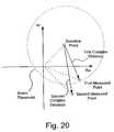
- a method for evaluating a measurement signal against a reference signalcomprises converting a reference signal having magnitude and phase to a complex form and plotting the complex form reference signal in a complex plane to form a reference point.
- a measurement signalis converted into a complex form and also plotted in the complex plane to form a measurement point.
- the complex distance between the reference point and the measurement pointis determined and the complex distance is compared to a threshold.
- the methodmay further comprise the step of generating the reference signal by taking a reference or baseline measurement.
- a method for evaluating measurement signals against reference signalscomprises taking measurements at a plurality of frequencies to generate a plurality of reference signals and converting the plurality of reference signals having magnitude and phase to a complex form.
- the complex form reference signalsare plotted in a complex plane to form a plurality of reference points. Measurements are taken at the plurality of frequencies to generate a plurality of measurement signals which are also converted into a complex form.
- the complex form measurement signalsare plotted in the complex plane to form a plurality of measurement points. A plurality of complex distances between the reference points and corresponding ones of the measurement points are determined and compared to a corresponding plurality of thresholds.
- This methodmay further comprise normalizing the reference signals by multiplying all reference signals by a normalization factor so that the maximum reference signal becomes one, and multiplying all measurement signals by the normalization factor.
- the plurality of thresholdsmay vary as a function of frequency and, to boost performance, vary such that lower threshold values are used at frequencies where sensor performance is higher.
- a method for evaluating measurement signals against reference signalscomprises taking measurements at a plurality of frequencies to generate a plurality of reference signals and converting the plurality of reference signals having magnitude and phase to a complex form.
- the complex form reference signalsare plotted in a complex plane to form a plurality of reference points.
- Measurementsare taken at the plurality of frequencies to generate a plurality of measurement signals that are converted into a complex form and also plotted in the complex plane to form a plurality of measurement points.
- a plurality of complex distances between the reference points and corresponding ones of the measurement pointsare determined and a threshold based on the plurality of reference points is determined.
- a complex distance curveis determined based on the plurality of complex distances and the area under the complex distance curve is compared to the threshold.
- a sensorcomprises at least two sensor elements with each sensor element comprising a substrate and a superstrate mounted to the substrate and having a base facing the substrate and an outer surface extending away from the substrate.
- a generally planar antenna elementis accommodated by and mounted between the substrate and the superstrate.
- a housingsupports the at least two sensor elements to maintain a predetermined distance between the two sensor elements.
- the housingmay comprise a resilient material such as polyurethane and may be shaped, and the sensing elements positioned within the housing, to permit visual observation and palpation of body tissue interposed between the at least two sensor elements.
- the housingis shaped like a bowtie having two expanded portions interconnected by a portion more narrow than the expanded portions, each of the two expanded portions having at least one sensor element housed therein.
- the housingmay have first and second elongated portions interconnected by a third elongated portion, with each of the first and second elongated portions having at least one sensor element housed therein.
- the sensor housingis generally U-shaped to permit visual observation and palpation of body tissue interposed within the open end of the U-shaped housing.
- the sensormay comprise at least four sensor elements with at least two of the sensor elements defining at least two electromagnetic wave transmitters and at least two of the sensor elements defining at least two electromagnetic wave receiver elements with the at least two electromagnetic wave transmitters being positioned opposite the at least two electromagnetic wave receivers.
- the at least two electromagnetic wave transmitterscan be separated from the at least two electromagnetic wave receivers by body tissue to be monitored by electromagnetic waves and the planar antenna elements of the at least two sensor elements can be square and be electrically contacted adjacent inner corners of the elements to induce circular polarization of the electromagnetic waves.
- a sensor element for injecting and/or receiving electromagnetic waves into body tissuecomprises a housing having a substrate mounted therein.
- a superstrateis mounted to the substrate and has a base facing the substrate and an outer surface facing away from the substrate.
- a generally planar antenna elementis accommodated by and mounted between the substrate and the superstrate with the housing extending to the outer surface of the superstrate and an electrical shield provided to surround the sensor element except for the outer surface of the superstrate.
- the housingis flush with the outer surface of the substrate.
- the housingis recessed below the outer surface of the superstrate and defines a transitional periphery interconnecting the housing to the outer surface of the superstrate, wherein at least a portion of the transitional periphery has a generally smooth transition from the base to the surface plateau.
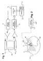
- FIG. 1illustrates a detection system in which the sensors and sensor elements of the invention of the present application can be used.
- FIG. 2illustrates the detection system of FIG. 1 in use to detect extravasation.
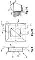
- FIG. 3illustrates a first antenna array positioned about an injection site for use in the detection of extravasation.
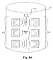
- FIG. 4Aillustrates a second embodiment of an antenna array including tapered-slot antennae.
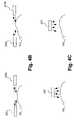
- FIG. 4Billustrates a side view of use of an antenna array as illustrated in FIG. 4A to pass electromagnetic energy across a surface to detect a change in, for example, the geometry, shape or morphology of the surface corresponding to a change in fluid level or material presence in underlying tissue.
- FIG. 4Cillustrates a side view of an antenna used to transmit electromagnetic energy to and measure reflected electromagnetic energy from a surface to detect a change in, for example, the geometry, shape or morphology of the surface corresponding to a change in fluid level in underlying tissue.
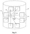
- FIG. 5illustrates a second antenna array positioned about an injection site for use in the detection of extravasation.
- FIG. 6illustrates an embodiment of a transmitter and/or receiver including a coupling or superstrate layer suitable for coupling the transmitter/receiver to the skin.
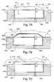
- FIG. 7Aillustrates a side, cross-sectional view of an embodiment of an antenna including a sensor element of the present invention with a linearly tapered superstrate.
- FIG. 7Billustrates a side, cross-sectional view of the antenna of FIG. 7A coupled to a patient's arm.
- FIG. 7Cillustrates a side, cross-sectional view of an antenna of the present application with a square superstrate coupled to a patient's arm.
- FIG. 7Dis a plan view of the antenna or FIG. 7A showing resonance sizing of a square patch antenna and a circular patch antenna, one of many alternate patch antenna geometries.
- FIG. 7Eis a broken-away, side, cross-sectional view of an alternate embodiment of an antenna of the present invention showing a curvilinear tapered superstrate.
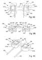
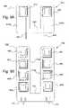
- FIG. 8Aillustrates a bottom view of a “bowtie” sensor of the present invention including two antenna as illustrated in FIGS. 7A and 7B .
- FIG. 8Billustrates a side, cross-sectional view of the sensor of FIG. 8A .
- FIG. 8Cillustrates a perspective view of the sensor of FIG. 8A .
- FIG. 8Dillustrates a side view of the sensor of FIG. 8A coupled to a patient's arm.
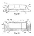
- FIG. 8Eillustrates a side, cross-sectional view of an embodiment of an antenna of the present invention positioned within a base member having a tapered profile to assist in conforming to tissue.
- FIG. 9Aillustrates a bottom view of a U-shaped sensor of the present invention including two antenna as illustrated in FIGS. 7A and 7B .
- FIG. 9Billustrates a bottom view of a U-shaped sensor of the present invention including two linear arrays of four antennae as illustrated in FIGS. 7A and 7B .
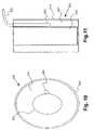
- FIG. 10illustrates a top view of an embodiment of a phantom used to model elevated or otherwise abnormal fluid levels in the human body.
- FIG. 11illustrates a side, cross-sectional view of the phantom of FIG. 7 .
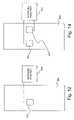
- FIG. 12illustrates an experimental setup in which a single antenna was used as both the transmitter and receiver.
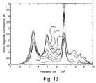
- FIG. 13the effect of increasing fluid level on the received signal in the setup of FIG. 9 .
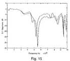
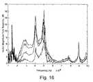
- FIG. 14illustrates an experimental setup in which one antenna was used as a transmitter and another antenna was used as a receiver.
- FIG. 15illustrates a comparison of the resonance frequencies of the two antennae of FIG. 14 .
- FIG. 16the effect of increasing fluid level on the received signal in the setup of FIG. 14 .
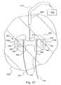
- FIG. 17illustrates the sensor of FIG. 8A in connection with a chicken phantom.
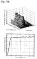
- FIG. 18illustrates signal data resulting from extravasation studies on a single-skinned chicken phantom.
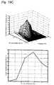
- FIG. 19Aillustrates “complex distance” as a function of injected volume and frequency in the upper graph and maximum “complex distance” over all frequencies as chicken phantom.
- FIG. 19Billustrates “complex distance” as a function of injected volume and frequency in the upper graph and maximum “complex distance” over all frequencies as a function of injected volume in a lower graph for another extravasation study on a double-skinned chicken phantom.
- FIG. 19Cillustrates “complex distance” as a function of injected volume and frequency in the upper graph and maximum “complex distance” over all frequencies as a function of injected volume in a lower graph for an extravasation study on a single-skinned chicken phantom.
- FIG. 20illustrates a graphical representation of “complex distance”.
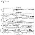
- FIG. 21Aillustrates signal data resulting from studies using the sensor of FIG. 8A on a human subject on areas of varying fat layer thickness.
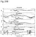
- FIG. 21Billustrates signal data resulting from studies using the sensor of FIGS. 8A on another human subject on areas of varying fat layer thickness.
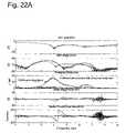
- FIG. 22Aillustrates signal data resulting from studies using the sensor of FIG. 8A on a human subject's arm at various arm positions.
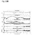
- FIG. 22Billustrates signal data resulting from studies using the sensor of FIG. 8A on a human subject's arm at various arm positions wherein sensor cables were maintained in separation.
- FIGS. 23 and 24illustrate an alternate embodiment of a sensor with opposing directional planar antennae.
- While the sensors and methods of the present inventionare generally applicable to the sensing of bodily or injected fluid levels or other foreign materials of the levels of such foreign materials in tissues, they will be described herein primarily with reference to extravasation for which it is particularly applicable and initially being utilized.
- Complex permittivity and permeabilitygovern how an electromagnetic wave will propagate through a substance. Complex permittivity typically has the greatest effect since it varies significantly between tissue types and fluids of interest. The complex permeability of various tissues and many fluids of interest is approximately that of a vacuum, reducing the effect of this parameter. However, some fluids such as MRI contrast agents may have an appreciable complex permeability difference from tissue. Although blood contains small amounts of iron, the permeability value for any significant volume of blood is typically insignificant.
- ⁇ ′′is the imaginary component of the complex value and is often referred to as the “loss factor.”
- the ratio of ( ⁇ ′′/ ⁇ ′)is known as the “loss tangent.”
- the complex permittivity (and sometimes permeability) of certain substancesdiffer from the body tissue at certain frequencies. Such differences in permittivity and/or permeability are used for the detection and level monitoring of certain fluids and substances in biological tissue.
- electromagnetic energyhaving, for example, a frequency in the range of approximately 300 MHz to approximately 30 GHz (and, more preferably, in the range of approximately 1 GHz to approximately 10 GHz, and, even more preferably, in the range of approximately 3 GHz to approximately 5 GHz) provides good penetration into tissue.
- electromagnetic energyis launched into the subcutaneous tissue and a resultant signal is measured.
- Electromagnetic energy in the frequency range set forth abovehas been found to transmit through the skin and to transmit or propagate well within, for example, fat. Good transmission through the fat layer is beneficial for detection of extravasation as many extravasations occur in the fat layer.
- the sensitivity to extravasation of the systems and methods utilizing the present inventionis thus increased as compared, for example, to impedance plethysmography wherein the majority of the electrical current passes through highly conductive layers such as skin and muscle where extravasation is much less likely to occur.
- the presence or level of a foreign material, liquid, body fluid, or substance in the subcutaneous tissuecan be determined.
- One or more electromagnetic sources 10typically antennae, transmit electromagnetic waves into the tissue in an area of interest, for example, a portion of an arm 100 of a human patient as shown in FIG. 1 .
- the scattered and/or reflected electromagnetic wavesare then received by the launching antenna(e), represented by the dashed line in FIG. 1 , and/or by one or more receiving antenna(e) 20 .
- a signalcan be transmitted and received with a single antenna which acts as both the source and the sensing element.
- using multiple receiving antennaecan be advantageous as noise, motion artifacts, and other anomalies can sometimes be more readily discerned from changes due to abnormal levels of fluid/substance of interest.
- a signalis supplied to the active antenna(e) 10 from one or more signal sources 30 .
- the signal source(s) 30is preferably in communicative control with a data processing and the control unit 40 , for example, a computer.
- the control unit 40can be in communication with a user interface 50 , for example, a keyboard, a monitor etc., and an alarm 60 .
- the data processing and control unit 40is also preferably in communication with a signal processor 70 which receives signals from the antenna 10 and/or the antenna 20 .
- the detection system illustrated in the present applicationis well suited for the detection of abnormal and/or changing levels of a variety of fluids in the human body, including both body fluid and foreign substances.
- one or more antennae as described abovecan be used to determine if an extravasation has occurred during an injection procedure.
- antenna(e) designs, configurations and/or placementsare described below in the context of detection or determination of extravasation.
- FIG. 2illustrates the use of the detection system of FIG. 1 in the detection of an extravasation 120 during an injection procedure.
- the transmitting antenna 10 and the receiving antenna 20are positioned on opposing sides of an injection site wherein a catheter 160 is positioned within, for example, a vein 110 .
- the catheter 160can, for example, be in operative connection with a source of pressurized injection fluid such as a syringe 170 in connection with a powered injector 180 as known in the art.
- the detection systemuses electromagnetic waves in the RF and microwave region, well below the optical frequency range.
- Applicators/antennae to transmit and/or receive electromagnetic energy for use in the present inventionare, for example, resonant structures and may take on several forms including, but not limited to, the following: microstrip antenna(e), waveguide(s), horn(s); helical antenna(e) and dipole antenna(e) as known in the art.
- microstrip antennarefers generally to a thin, low-profile antenna of a wide variety of patterns including, but not limited to, linear, square, circular, annular ring, triangular, rectangular, dipole, tapered slot, planar spiral and others.
- resonant structures or other energy transmitting antennaeinteract with the tissue of interest via nearfield interactions and propagated waves. Energy is exchanged with the tissue in the nearfield and waves are propagated into the tissue. Reflections and scattering occurs at boundaries when permittivity and/or permeability variations and differences occur.
- a measured signalis compared to a reference signal or signals to determine if an abnormal (for example, elevated) level of fluid is present in the area of tissue being monitored.
- a reference signalcan, for example, be a baseline signal that is measured when the fluid/substance level of interest is known or in a known state.
- a search modeis entered where changes in reflected or scattered waves are detected by measuring the received signal(s) and comparing them to the reference signal(s). If, for example, the measured signal deviates from the reference signal by a predetermined amount or in a predetermined manner, the alarm 60 can be activated. In an injection procedure, the injection can be stopped upon activation of the alarm 60 .
- the control unit 40can be in communication with the powered injector 180 to stop an injection procedure upon detection of extravasation.
- Measurements and signal processingcan be made in the time domain and/or the frequency domain as known in the art.
- the signal sourceis generally a sinusoidal wave source in which the frequency is swept or stepped through a desired frequency range.
- the magnitude and/or phase of the measured signalcan be compared to the magnitude and/or phase of the reference signal to detect changes of, for example, a pre-determined amount.
- the signal sourcecan be a substantially narrow impulse or sharp step that excites the resonant modes of the sending antenna(e) which in turn launch electromagnetic waves into the tissue of interest. Fluid or substance presence or level changes alter the received signal(s) such that they differ from the reference signal in terms of delay, frequency content, and/or overall shape.
- the detection systemalso embodies other types of measurements and signal processing.
- measurement modescan include, for example, antenna impedance or resonant mode frequency shift detection.
- more sophisticated signal processing techniques of the reference and/or received signalscan be employed.
- the signalsmay be mathematically manipulated, such as averaged, integrated, median filtered, band pass filtered, low pass filtered, or high pass filtered in the time or frequency domain to emphasize subtle patterns in the data that may not be as readily apparent when simple reference subtraction/comparison is performed.
- to compare or to make a comparisonrefers to making a decision or judgment based upon a relationship between two or more measurements, sets of measurements, or functions of measurements.
- the relationshipis generally expressed as a mathematical relationship, algorithm or heuristic. For example, a comparison of magnitude or “complex distance” from a reference or baseline measurement, as further described below, can be made. It is also possible to compare the slopes or rate of change of the received and reference signals.
- An algorithm similar to that applied in statistical process controlcan, for example, be applied whereby an abnormality is judged to occur if more than a predetermined number of successive measurements, for example four successive measurements, are on one side of the reference signal, or if one measurement is outside of a standard band, or if there is a trend of a predetermined number of measurements, for example seven measurements, moving in a consistent direction.
- a predetermined number of successive measurementsfor example four successive measurements
- a first antenna array positioned about an injection site illustrated in FIG. 3two generally linear arrays of antennae are used.
- one array of antennaeis an active, launching/transmitting, array 200 and an opposing array of antennae on the other side of the injection site is a passive, receiving, array 220 .
- the signal source of the systemexcites or drives the active array 200 via, for example, amplifiers by using sinusoidal or impulse waveforms.
- the signal source(s)create an electromagnetic wave which is launched generally normally (perpendicularly) to the skin surface and into the subcutaneous tissue. The wave then scatters and propagates through the subcutaneous tissue (for example, through adipose/fat tissue).
- the antennae of the passive antennae array 220then receive the signals which are, in turn, processed by the signal and data processing subsystems.
- the received or measured signalsare then compared to the reference, for example baseline, signals that were collected during the baseline procedure.
- baseline measurementscan be repeated or updated to create a running baseline.
- microstrip antenna designsare suitable for use in the present invention including: line, square, circular, annular ring, triangular, rectangular, dipole, tapered slot, planar spiral and others. In general, any design that yields sufficient energy coupling in the preferred frequency ranges set forth above are suitable for use in detection system.
- FIG. 4Aa generally linear array 240 of transmitting microstrip antennae with a tapered-slot design are illustrated.
- the tapered-slot designyields improved directionality and increased bandwidth.
- the antennae or array 240are angled toward the skin of arm 100 so that the waves can be launched into the tissue, yet in the general direction toward a passive/receiving antennae 260 .
- Use of such tapered-slot antennaecan improve signal coupling and overall sensitivity.
- electromagnetic wavesare propagated in the vicinity of the surface of the skin or other body surface using antennae, for example arrays of antennae as illustrated in FIG. 4A , above or close to the surface.
- the propagated wavesinteract with the surface in a manner that is affected by the surface shape, geometry or morphology.
- This methodcan be useful, for example, when the tissue of interest has a thin fat layer.
- surface/skin deformation caused by the fluid/substance of interestcan be detected by monitoring signals reflected and/or scattered by the surface.
- Tapered-slot antennae in a configuration similar to that shown in FIG. 4Acan, for example, be used to propagate surface waves across moderately conductive skin. For example, FIG.
- FIG. 4Billustrates transmission of electromagnetic waves across the surface of the arm 100 by a pair of transmitting/receiving antennae 250 a and 250 b .
- Surface deformation caused by changed, elevated or abnormal fluid levels (for example, extravasation)induce a change in the signal measured by the antenna(e) 250 a and 250 b .
- FIG. 4Cillustrates another embodiment in which a transmitting/receiving antenna 260 transmits electromagnetic energy generally normal to the surface of the arm 100 and receives a reflected signal. Once again, surface deformation induces a change in the measured signal.
- separate transmitting and receiving antennaecan be used as described above as either a single antenna pair or as an array of multiple transmitting/receiving antennae.
- FIG. 5Another embodiment of a multiple antenna configuration or antenna array is shown in FIG. 5 wherein a plurality of individual antennae 310 are arranged to surround the area to be monitored.
- the web array of antennae 310 in FIG. 5enables a phasing approach to concentrate the wave energy at a particular location 320 .
- the phased drive signals to each antennacan then be altered such that the focal point 320 is moved in a scanning pattern.
- This phasing approachcan increase the overall sensitivity of the system.
- directional couplerscan be employed, as known in the art, to allow the transmitting antennae in the web array to also perform as receiving antennae simultaneously.
- Directional couplersare used in equipment such as network analyzers to allow the analyzer to send energy to a device, like an antenna, while simultaneously receiving reflected energy from the device/antenna. Therefore you can transmit and receive on an antenna simultaneously.
- the detection system illustrated in the present applicationis not limited to the antenna configurations or arrays set forth above.
- a wide variety of antenna configurationsare suitable for use in the present invention.
- any antenna configuration positioned near the anticipated location of the liquid or substance to be detected or monitoredis suitable.
- extravasationtypically occurs in the immediate vicinity of the injection site, near the position of the catheter tip. Extravasation may sometimes occur, however, at a site remote from the injection site.
- extravasationcan be detected at the injection site and at site(s) remote from an injection site (generally along a path of potential extravasation) using, for example, antennae positioned as an array along a path of potential extravasation.
- Couplingcan, for example, be improved by providing a layer of material in contact with the skin/other surface of interest (for example, the surface of an internal organ) that couples with the surface by having an intrinsic impedance similar to the surface.
- a layer of materialin contact with the skin/other surface of interest (for example, the surface of an internal organ) that couples with the surface by having an intrinsic impedance similar to the surface.
- Such materialmay comprise, for example a relatively high permittivity, low-loss material, such as magnesium calcium titanium dioxide, MgCaTiO2.
- a disposable de-ionized water pouchcan also be used.
- deformation of such a water pouch or container during use thereofis limited as deformation can impact the received or measured signal.
- FIG. 6illustrates a sensor 350 in accordance with the present invention wherein an intermediate, spacing or superstrate layer 360 of a coupling material as described above is in direct contact with the skin of the arm 100 , while an antenna, for example, a resonant structure 370 , is spaced from the skin by the intermediate or superstrate layer 360 .
- resonant structure 370is positioned within a substrate 380 and the sensor is shielded up to the transmitting/receiving face 362 of the sensor.
- a microstrip antenna 350 ′ used in several studies that led to the invention of the present applicationwas structured substantially the same as the sensor 350 but without the shielding.
- FIGS. 7A and 7Billustrate an embodiment of a microstrip antenna 400 in accordance with the present invention.
- the antenna 400includes a superstrate layer 410 fabricated from a coupling material and having an outer surface extending away from the substrate 430 which contacts the skin of the arm 100 , see FIG. 7B .
- An antenna or resonant structure 420is positioned on a substrate 430 .
- the antennae or resonant structures of the present inventionare fabricated from a conductive material such as copper, silver, gold or other appropriate material as known in the art.
- the substrate materialis a moderate to high permittivity, low-loss material, such as MgCaTiO2, and is often the same as the superstrate to prevent discontinuities between the substrate and the superstrate.
- a moderate to high permittivity, low-loss materialsuch as MgCaTiO2
- MgCaTiO2low-loss material
- prototypes with differing materials for the superstrate layer and substrate layerhave been fabricated and successfully operated.
- any material with moderate to high permittivity valuesfor example, in the range of approximately 10 to approximately 100 and, more preferably, in the range of approximately 50 to approximately 80
- low-loss characteristicssuch that its intrinsic impedance is reasonably close to the surface of the tissue to be interrogated will be suitable.
- materials with low moisture absorption characteristics and low permittivity to temperature correlationare also desirable.
- the antennaewere fabricated from a ceramic laminate material coated with thin layers of copper on the front and back thereof.
- a product sold under the name RT/duroid® 6010LM by Rogers Corporation of Chandler, Ariz.was used.
- Such microwave laminatesare ceramic-PTFE (polytetrafluoroethylene) composites designed for electronic and microwave circuit applications requiring a relatively high dielectric constant or permittivity.
- RT/duroid 6010LM laminatehas a dielectric constant of 10.2 ⁇ 0.25.
- the laminates used to fabricate the microstrip antennaewere approximately 2.5 mm thick for the substrate and 1.25 mm for the superstrate and were supplied with both sides thereof clad with 1 ⁇ 2 oz./ft 2 electrodeposited copper foil (cladding thickness of approximately 16 ⁇ m -1 ⁇ 4 to 2 oz./ft 2 electrodeposited copper foil available with cladding thicknesses of 8 ⁇ m to 70 ⁇ m).
- some of the copper materialwas etched from the top of the laminate to form a generally planar microstrip antenna element or resonant structure 420 , thereby forming a margin between the outer edge of the resonant structure 420 and the outer edge of the substrate 430 .
- a margin d(see FIG. 7A ) was created between the resonant structure 420 and the periphery of the substrate 430 .
- the copper on the bottom side of the laminateforms a ground plane 440 for the antenna 400 .
- Side shielding 450 of a conductive materialcan be provided to, for example, improve tissue coupling and reduce the leakage of stray energy.
- stray surface wavescan, for example, increase motion and other artifacts.
- stray or side energycan also be used to monitor surface geometry changes as discussed above in connection with FIGS. 4A through 4C .
- Silver side shieldingwas used in several antennae of studies leading to the present invention.
- Side shielding 450 and ground plane 440form an electrically conductive cavity C.
- the resonant structure 420 and the cavity Cresonate together in the frequency range of interest. Such resonance improves efficiency by increasing power output relative to power input for transmission, and power received relative to power available for reception for receipt.
- margin sizeimpacts resonance of a patch or resonant structure with a cavity. It was found by the present inventor that when the diagonal dimension 420 d (see FIG. 7D ) of a square resonant structure 420 is generally equal to the non-diagonal distance or side width 400 w across the cavity C (total antenna width), resonant structure 42 and the cavity C resonate together in the frequency range of interest.
- the first mode of the resonant structure or patch 420resonates with the second resonant mode of the cavity C.
- the matching of the diagonal dimension 420 d with the non-diagonal distance or side width 400 wdetermines the size of margin d.
- Circular resonant structures 410were used in the studies resulting in the present invention, it is clear to one skilled in the art that many alternative antenna element or resonant structure geometries, including for example circular or rectangular, can be used in the sensor elements and sensors of the present invention. Circular resonant structures can, for example, provide increase bandwidth as compared to square resonant structures in certain embodiments.
- Energyis supplied to the resonant structure 420 via, for example, a microcoaxial cable 460 as known in the art. Energy can be supplied to an inner corner of the resonant structure 420 to induce circular polarization which can improve coupling between antennae by decreasing the sensitivity of such coupling to the relative orientations of the antennae.
- a base of the superstrate layer 410was secured to the substrate 430 using an appropriate adhesive, such as a cyanoacrylate or “superglue.” In that construction, potential air pockets adjacent the resonant structure 420 are filled with the superglue to substantially avoid any negative effect on transmission of the microwaves.
- an indentation corresponding to and receiving the resonant structure 420can be formed on the underside of the superstrate layer 410 .
- Such an indentationcan also or alternately accommodate a solder bump SB formed by connection of the center conductor of the microcoaxial cable 460 .
- the antennae superstrate layerwas fabricated from a ceramic filled PTFE laminate material reinforced with woven fiberglass available from Rogers Corporation of Chandler, Ariz. under product number RO3210. That material has a dielectric constant of 10.2 ⁇ 0.5. It was discovered that beveling the edges of the superstrate layer 410 to form a transitional periphery 421 interconnecting a base B of the superstrate layer 410 to an outer surface plateau 423 extending over at least a central portion of the superstrate layer 410 improved skin conformance and reduced motion artifacts in a measurement signal resulting from patient movement, see FIG. 7A . As illustrated, for example, in FIGS.
- the outer edges of the superstrate layer 410are beveled at an angle ⁇ which is greater than 0° and less than 90°.
- ⁇is between approximately 20° and 50°.
- ⁇was approximately 30°.
- the superstrate layer 410can have only a portion tapered so that it can also direct energy in the direction of the tapered portion, for example toward a receiving antenna in the manner of a “microwave lens” to improve transmission between antennae. Rather than a linear taper as shown in FIGS.
- the tapercan be a smooth curvilinear surface CS, as shown in FIG. 7E , to improve the conformance of the superstrate 410 to a patient's skin.
- FIG. 7Cillustrates an antenna 400 ′ which is substantially identical to the antenna 400 except that the superstrate 410 ′ of the antenna 400 ′ is square, rather than being beveled or curvilinear.
- the skin tissue of the arm 100does not conform as well to the contour of the antenna 400 ′ as it does to the contour of the antenna 400 , resulting in the formation of air pockets p on the periphery of the antenna 400 ′.
- air pocketscan, for example, scatter the microwave energy, negatively affect coupling and cause increased artifacts as a result of subject patient motion.
- Antennae of the sensor elements/sensors of the present inventioncan be made to have somewhat directional transmission and/or reception of microwaves by having only a portion of the transitional periphery of the outer surface of the superstrate have a generally smooth transition from the base of the superstrate to the surface plateau of the superstrate in the desired directional transmission and/or reception.
- the antenna 400 ′ as shown in FIG. 7Ccan be made to be provide directional transmission and/or receipt of microwaves by making only a portion, such as one side of the transitional periphery 411 ′, have a generally smooth transition so that transmission and/or reception is improved in that direction, to the right side of FIG. 7C .
- the shield 450 ′should be extended as shown by the dotted lines.
- one or more pairs of antennaecan be mated to favor transmission by one antenna and receipt by its mate.
- the injection sitepreferably remains open or available for visualization and/or palpation.
- the sensors and methods of the present inventionreadily afford such availability.
- a plurality of antennaecan be placed on the subject/patient in a disconnected state.
- FIGS. 8A through 8Dillustrate a sensor 500 including a sensor support, housing or base member 505 that is shaped like a “bowtie” having first and second expanded portions or base sections 510 a , 510 b interconnected by a more narrow portion or flexible bridge 520 .
- the flexible bridge 520allows some bending and/or twisting of the first base section 510 a and the second base section 510 b relative to each other to conform to, for example, a patient's arm or other region of interest.
- the base sections 510 a , 510 beach receive or house an antenna 400 with the bridge 520 generally or approximately maintaining a predetermined distance or range of distances between the antennae 400 , while providing the needed flexibility to conform to a patient's tissue, see, for example, FIG. 8D , and allowing access to the vicinity of the detection area, for example, an injection site in an extravasation detection.
- the sensor base 505is thus preferably fabricated from a durable, flexible/resilient material having a relatively low dielectric constant.
- Many polymeric materialssuch as, for example, polyurethane, are suitable for fabrication of the sensor base 505 .
- the sensor base 505was molded from an integral piece of polyurethane. It is also contemplated that the sensor base 505 can be fabricated of more rigid materials for given applications.
- the linear taper or smooth curvilinear surfacedescribed above relative to the superstrate 410 , can be formed on the sensor support, housing or base member 510 a ′′, see FIG. 8E , rather than on the superstrate 410 ′′ to assist in conforming to tissue.
- the superstrate 410 ′′ in such an embodimentcan be made generally flat or planar over its outward transmitting/receiving surface 412 ′′.
- a support, housing or base memberdefines the taper, linear or curvilinear, or is generally flush with the face of an antenna, such as antenna 400 ′′
- the shielding 450 ′′ for antenna 400 ′′can be extended to the transmitting/receiving face 412 ′′ of superstrate 410 ′′ as illustrated in FIG. 8E . Also see FIG. 6 .
- the bridge 520maintains a separation between the first base section 510 a and the second base section 510 b and the respective antennae 400 to ensure suitable coupling and to provide visual and tactile access to the injection site as defined, for example, by a catheter tip.
- FIGS. 9A and 9Billustrate alternative embodiments of sensors 600 , 700 of the present invention that provide flexibility to conform to the patient's tissue and allow access to the vicinity of the detection area, for example, an injection site in an extravasation detection application.
- the sensor 600 of FIG. 9Ais a generally U-shaped sensor including a sensor support, housing or base member 605 having a first base section 610 a and a second base section 610 b connected by a bridge 620 .
- the sensor base 605is preferably fabricated from a resilient material such as a polyurethane; however, other more rigid materials are contemplated for use in the present invention.
- Each of the first base section 610 a and the second base section 610 bsupports an antenna 400 as described above.
- the sensor 700 of FIG. 9Bis also a U-shaped sensor including a sensor support, housing or base 705 having a first base section 710 a and a second base section 710 b connected by a flexible bridge 720 .
- the sensor base 705is also preferably fabricated from a resilient material such as a polyurethane; however, other flexible materials and more rigid materials can be used.
- Each of the first base section 710 a and the second base section 710 bsupports a linear array of antennae 400 . While each of the antennae 400 are shown as being the same size, the sizes of the antennae can vary to provide various resonance frequencies of interest for the sensor or to generally increase the bandwidth of the sensor and therefore frequency range over which it is sensitive.
- Each of the antennae 400 of the sensor 700 of FIG. 9Bcan be connected to a power source/measurement device via individual wires or connective paths.
- integrated power/signal splittersas known in the art, can be used.
- power splitterscan be integrated into microstrip (planar) antenna designs, such that an array of antennae located on one layer can be fed through apertures located on another layer which are in turn fed by a power splitter and feeds on a third layer.
- This structureallows the simultaneous feeding of multiple transmitting antennae with one input signal or connection 730 .
- Such a splitting methodis also an effective method of combining signals from multiple receiving antennae into one signal or connection 740 to be processed.
- Adjustments in phasing for the antennae that make up the transmitting/receiving arrayscan be done during the design phase, but will be fixed once the device is fabricated.
- This methodcan offer advantages in sensors of the present invention by, for example, improving directionality and therefore signal-to-noise ratio (SNR) for the sensor.
- SNRsignal-to-noise ratio
- FIG. 23illustrates another embodiment of a sensor 750 of the present invention with sensor elements comprising opposing directional planar antennae 752 .
- the directional planar antennaeare structured similar to the antennae used in the other sensors of the present application with an antenna element 754 mounted between first and second substrates 756 , 758 with shielding 759 surrounding the antennae except for the electromagnetic emitting/receiving faces adjacent to tissue 761 being sensed.
- the directional planar antennae 752are structured to emit microwaves from the ends or edges 760 of the antennae 752 rather than from the planar faces of the antennae.
- FIG. 24illustrates an experimental mounting arrangement wherein the angular orientations of the antennae 752 relative to each other can be varied.
- an angular orientation ⁇ ′ of approximately 30° to a surface of a body to be sensedi.e., an angle ⁇ ′′ of approximately 120° relative to each other, is believed to be preferred; however, the specific angular orientations can be any reasonable value required for a given application and it is contemplated that different angular orientations can be used for each of the antennae.
- the antennae of the present inventionthat were used for this experiment were designed to resonate at an intermediate frequency of approximately 4 Ghz.
- microstrip antennae used in the studies leading to the present inventionwere designed using Finite Difference Time Domain (FDTD), a well known modeling technique. Standard equations, generally available for well-understood geometries, were used to determine approximate dimensions required for the resonant structures of the various antennae in the studies resulting in the present invention. Following that, substrate thickness was chosen to be a fraction of the wavelength corresponding to the primary resonant mode of the resonant structure. Finally, FDTD simulation techniques were used to refine dimensions and determine the best location for the feed connection. A FDTD software package available from Remcom Inc. of State College, Pa. was used for the design of the antennae which were then etched and fabricated using well known laboratory techniques.
- FDTDFinite Difference Time Domain
- the microstrip antennaeincluded a ceramic material coated with thin layers of copper for the resonant structure and ground plane as described above in connection with FIGS. 6 and 7 A- 7 E.
- other materialssuch as gold or silver, can be used for the resonant structure.
- the phantom 800included emulated skin 810 , comprising carbon-loaded foam, an emulated fat layer 820 , comprising glycerin, and a movable, emulated muscle bundle 830 , comprising “Ultravist 370” contrast medium or contrast agent available from Schering AG of Berlin, Germany as illustrated in FIGS. 10 and 11 .
- the emulation materialswere chosen to approximate the dielectric properties of the tissues to be emulated.
- the microstrip patch antennae 350 ′, 350were designed to couple efficiently into tissue as described in connection with FIG. 6 .
- By spacing the resonating patch element 370 from the skin layer 810 as illustrated in FIG. 6one can reduce near-field loading.
- the substrate thicknesswas approximately 2.5 mm and the superstrate thickness was approximately 1.5 mm.
- the relative permittivity values at 5 GHz for each of the substrate 380 and the superstrate 360were 10.2 and 20, respectively.
- a single antenna 350 ′was applied to phantom 800 generally directly over the extravasation site, i.e., the balloon 850 .
- the configurationis shown in FIG. 12 .
- the emulated skin 810 and the muscle bundle 830were both in place during these experiments.
- S 11 measurements, i.e., microwaves transmitted on a first antenna, port 1 , and received on the same antenna, port 1were made using network analyzer 900 to detect changes in the reflected energy created by the antenna 300 .
- the results from these experimentsare shown in FIG. 13 .
- the baseline in the experimentscorresponded to having the balloon 850 filled with approximately 1-2 cc of Ultravist 370.
- the setup for the dual patch antenna configurationis shown in FIG. 14 .
- S 11 measurementswere made with each of the patch antennae 350 ′ to determine if the antennae 350 ′ resonated at similar frequencies and, therefore, coupled effectively.
- the results of these measurementsare shown in FIG. 15 .
- the separation between the substrates 380 of the antennae in the dual patch antenna configuration of FIG. 14was approximately 1.0 cm, and the separation between active resonant elements 370 was approximately 2.5 cm.
- the substrate sizecan be changed, and separation distance can be changed. Parameters such as directionality, tissue coupling, data processing and signal processing were not optimized in these experiments.
- the results for the dual antenna configurationare shown in FIG. 16 .
- the baseline in this experimentcorresponded to having the balloon 850 filled with approximately 1-2 cc of Ultravist 370.
- the bowtie sensors 500were used to measure change during simulated extravasation using Ultravist 370 contrast medium.
- the spacing between the antennae 400was approximately 1.5 cm.
- Inner corner feedswere used to induce circular polarization.
- the substrate thicknesswas approximately 2.5 mm.
- the superstrate thickness, the distance between the resonant patch 410 and the outer surface plateau of the superstrate 420was approximately 1.25 mm.
- the resonant structure 410was square with a side length and width of approximately 8 mm. Margin widths d were approximate 2 mm. Taper angle ⁇ of the superstrate 420 was approximately 30°.
- FIG. 17illustrates attachment of the sensor 500 to a chicken phantom 1000 .
- the chicken phantom 1100was wrapped tightly in plastic wrap 1100 for purposes of sanitation and to assist in maintaining the shape of the phantom.
- the sensor 500was positioned on top of the plastic wrap 1100 .
- Double sided adhesive tape 475see FIG. 7B , available from 3M under product number/name 1512 , was applied to the bottom of the sensor 500 before being coupling to chicken phantom 1000 . In some studies, superglue was also placed between the double-sided tape 475 and the plastic wrap 1100 .
- Adhesive tape 575see FIG. 8D , was placed over the sensor 500 to secure the sensor 500 to the chicken phantom 1000 .
- Ultravist 370 contrast mediumwas injected/extravasated into chicken phantom 1000 via a catheter 1200 connected to a VISTORON CT® injector 1300 available from Medrad, Inc. of Indianola, Pa. via flexible tubing 1210 .
- FIG. 18illustrates data in several forms taken over a frequency range of 1 to 9 Ghz from a single-skin chicken phantom using the sensor 500 as described above.
- FIG. 18sets forth S 11 and S 22 data, i.e., microwaves transmitted on a second antenna, port 2 , and received on the second antenna, port 2 , S 21 magnitude data, “complex distance” data, S 21 delta magnitude data and delta phase from baseline data.
- FIGS. 19A-19Cillustrate “complex distance” as a function of frequency and volume injected in the upper graphs.
- the lower graphs of FIGS. 19A-19Cset forth the maximum “complex distance” over the measured range frequencies as a function of volume.
- FIG. 20provides a graphic illustration of a “complex distance” algorithm used in the studies leading to the present invention for a single frequency.
- the algorithmutilizes magnitude and phase information and enhances signal processing in frequency regions where signal coupling is strong.
- a reference or baseline signal(corresponding to 0 cc of injected contrast medium, for example) is first measured at each frequency or band of frequencies to be investigated.
- the magnitude and phase dataare converted to complex form, i.e., x+yi, and processed as illustrated by FIG. 20 , wherein the complex data points are plotted on a complex plane having its abscissa as the real (Re) part, x, and its ordinate as the imaginary (Im) part, y.
- the reference or baseline magnitude and phase measurementsthus become points in the complex plane.
- the magnitude and phase for measured data pointsare similarly converted to complex form and also plotted on the complex plane to become measured data points.
- the scalar distance between each baseline point and each measured data point at the corresponding frequencyis determined and each of these distances are referred to herein as a “complex distance,” see FIG. 20 .
- An alarm thresholdcan be defined for each frequency so that a plurality of alarm thresholds corresponding to the frequencies of the range of frequencies of interest can be defined.
- Each given alarm thresholdforms a circle around a baseline point having a radius of some pre-determined value that is above levels caused by random noise or normal motion disturbances corresponding to the alarm threshold, see the dashed circular line forming an alarm loci in FIG. 20 .
- the reference or baseline pointscan be reestablished as necessary during use of a sensor.
- the “complex distances” at the various frequenciesare calculated.
- the resultant valueis compared to a threshold number corresponding to the area under the reference or baseline curve across the frequency range of interest.
- a single “complex distance” at some frequency crossing the thresholdcan trigger an alarm.
- a sufficiently strong single “complex distance” or a group of such “complex distances”are required to create a sum/integral that exceeds a threshold value. It is also possible, for example, to accumulate individual “complex distance” comparisons with their corresponding thresholds and determine that an alarm will be indicated only if a predetermined number of the “complex distances” have exceeded their thresholds.
- the “complex distance” calculationmay yield significantly different values.
- the baseline or reference S 21 magnitude curvesare normalized by multiplying every point in the reference S 21 curve to force the peak value (or area under the curve) to equal one and then multiplying all subsequent measurement curves, curves created during actual operation of the detection system, by the same factor.
- Such normalizationhas been found to make the “complex distance” values more consistent when similar subcutaneous tissue changes occur in two different human subjects or in two different anatomical sites on the same human.
- FIGS. 19A and 19Bcorrespond to experiments with double skin chicken phantoms 1000
- FIG. 19Ccorresponds to an experiment with a single skin chicken phantom 1000
- the data of FIG. 18 and FIG. 19Care taken from the same experiment.
- FIG. 19Aa gradual signal increase is observed as the volume of injected contrast medium increases.
- FIG. 19Ba signal plateau is reached at injection of approximately 2 cc of contrast medium, indicative of signal saturation in the field of the sensor.
- FIG. 19Cthe signal increases to a maximum at approximately 4 cc of injected contrast medium and then subsequently decreases as more contrast medium is injected. It is believed, that tissue rupture may have led to dissipation of contrast medium from the tissue in the field of the sensor 500 in the experiment of FIGS. 18 and 19C .
- FIGS. 19A through 19Cindicate that the sensors of the present invention are sensitive to even small volumes of fluid in organic tissue.
- the shape of the “complex distance” curvecan, for example, indicate whether the fluid is pooled in the field of the sensor or dissipated therefrom.
- the sensor 500was also studied in several experiments with human subjects. In several such studies, signal output was measured at six different sites, for example side, abdominal, and upper forearm areas, having varying fat layer thicknesses as determined by skin fold measurements. Such measurements indicated fat layers of 2.5, 3.0, 4.0, 5.0, 8.0 and 12.0 mm.
- FIGS. 21A and 21Bset forth S 11 and S 22 data, S 21 magnitude data, “complex distance” data, S 21 delta magnitude data and delta phase from baseline data for each of the fat layer thicknesses over a frequency range of approximately 1 to 9 GHZ in two studies.
- the datademonstrate good skin and fat penetration of the energy of the sensor 500 into human tissue at all the fat thicknesses studied.
- the underside of the sensor 500was covered with double-sided adhesive tape 475 as illustrated in connection with FIG. 7A .
- the double-sided tapewas then placed in direct contact with the patients skin in the area of the antecubital fossa.
- Adhesive tape 575was then placed over the sensor 500 .
- the subject's armwas strapped in a jig to limit certain arm movements and the subject was led through six different arm position. In position 1 or the baseline position, the subject extended his or her arm to a straight position with the palm open and facing inward. In position 2 , the subject clenched his or her fist.
- position 3the subject bent his or her elbow approximately 45° inward and opened his or her hand.
- position 4the subject maintained the elbow angle of position 3 and clenched his or her fist.
- position 5the subject maintained the elbow angle of positions 3 and 4 and supanated the wrist.
- position 6the arm was straightened and the wrist flexed.
- FIGS. 22A and 22Bset forth S 11 and S 22 data, S 21 magnitude data, “complex distance” data, S 21 delta magnitude data and delta phase from baseline data for each of the above positions over a frequency range of approximately 1 to 9 GHZ in two studies.
- the datademonstrate that the effect of patient motion on the output signal or motion artifact is not large as compared to the signal effect of fluid introduction found in the phantom studies. Thus, motion artifacts will not present a substantial problem in, for example, detection of extravasation, and the effects of such artifacts can be further reduced via data manipulation such as averaging.
- precautionwas taken to prevent contact and excessive motion of the cable leads to the antennae 400 .
Landscapes
- Health & Medical Sciences (AREA)
- Life Sciences & Earth Sciences (AREA)
- Engineering & Computer Science (AREA)
- Biomedical Technology (AREA)
- Heart & Thoracic Surgery (AREA)
- Veterinary Medicine (AREA)
- Public Health (AREA)
- General Health & Medical Sciences (AREA)
- Animal Behavior & Ethology (AREA)
- Surgery (AREA)
- Medical Informatics (AREA)
- Molecular Biology (AREA)
- Pathology (AREA)
- Biophysics (AREA)
- Physics & Mathematics (AREA)
- Radiology & Medical Imaging (AREA)
- Nuclear Medicine, Radiotherapy & Molecular Imaging (AREA)
- Vascular Medicine (AREA)
- Immunology (AREA)
- Anesthesiology (AREA)
- Hematology (AREA)
- Measurement And Recording Of Electrical Phenomena And Electrical Characteristics Of The Living Body (AREA)
- Measuring And Recording Apparatus For Diagnosis (AREA)
- Investigating Or Analysing Biological Materials (AREA)
- Details Of Aerials (AREA)
- Arrangements For Transmission Of Measured Signals (AREA)
- Measuring Pulse, Heart Rate, Blood Pressure Or Blood Flow (AREA)
Abstract
Description
ε*=ε′−jε″
wherein ε′ is the real component of the complex value and is known as the dielectric constant or sometimes simply referred to as the “permittivity.” The term ε″ is the imaginary component of the complex value and is often referred to as the “loss factor.” The ratio of (ε″/ε′)is known as the “loss tangent.” The complex permittivity (and sometimes permeability) of certain substances differ from the body tissue at certain frequencies. Such differences in permittivity and/or permeability are used for the detection and level monitoring of certain fluids and substances in biological tissue.
Claims (58)
Priority Applications (1)
| Application Number | Priority Date | Filing Date | Title |
|---|---|---|---|
| US10/205,775US7591792B2 (en) | 2001-07-26 | 2002-07-26 | Electromagnetic sensors for biological tissue applications and methods for their use |
Applications Claiming Priority (2)
| Application Number | Priority Date | Filing Date | Title |
|---|---|---|---|
| US30801201P | 2001-07-26 | 2001-07-26 | |
| US10/205,775US7591792B2 (en) | 2001-07-26 | 2002-07-26 | Electromagnetic sensors for biological tissue applications and methods for their use |
Publications (2)
| Publication Number | Publication Date |
|---|---|
| US20030036674A1 US20030036674A1 (en) | 2003-02-20 |
| US7591792B2true US7591792B2 (en) | 2009-09-22 |
Family
ID=23192156
Family Applications (1)
| Application Number | Title | Priority Date | Filing Date |
|---|---|---|---|
| US10/205,775Expired - LifetimeUS7591792B2 (en) | 2001-07-26 | 2002-07-26 | Electromagnetic sensors for biological tissue applications and methods for their use |
Country Status (7)
| Country | Link |
|---|---|
| US (1) | US7591792B2 (en) |
| EP (3) | EP1414339B1 (en) |
| AT (2) | ATE343347T1 (en) |
| AU (1) | AU2002327367A1 (en) |
| CA (1) | CA2455402C (en) |
| DE (1) | DE60215668T2 (en) |
| WO (1) | WO2003009752A2 (en) |
Cited By (192)
| Publication number | Priority date | Publication date | Assignee | Title |
|---|---|---|---|---|
| US20040015087A1 (en)* | 2002-05-30 | 2004-01-22 | Olga Boric-Lubecke | Apparatus and method for heart size measurement using microwave doppler radar |
| US20040225255A1 (en)* | 2003-04-28 | 2004-11-11 | Nemoto Kyorindo Co., Ltd. | Leak detector for detecting leak of liquid injected into blood vessel using pulse signal |
| US20070173897A1 (en)* | 2004-09-02 | 2007-07-26 | Proteus Biomedical, Inc. | Methods and apparatus for tissue activation and monitoring |
| US20070225637A1 (en)* | 2004-09-14 | 2007-09-27 | Seiichi Ono | Leak Detecting Apparatus |
| US20100039111A1 (en)* | 2006-12-22 | 2010-02-18 | Koninklijke Philips Electronics N. V. | Rf coil for use in an mr imaging system |
| US20100175484A1 (en)* | 2007-05-02 | 2010-07-15 | Fathi Saigh | Sensor device to monitor deformation in structural members, such as solid structures |
| US20110130800A1 (en)* | 2009-12-01 | 2011-06-02 | Kyma Medical Technologies Ltd | Microwave Monitoring of Heart Function |
| WO2012059929A1 (en) | 2010-11-03 | 2012-05-10 | Sensible Medical Innovations Ltd. | Electromagnetic probes, methods for fabrication thereof, and systems which use such electromagnetic probes |
| US8412347B2 (en) | 2009-04-29 | 2013-04-02 | Proteus Digital Health, Inc. | Methods and apparatus for leads for implantable devices |
| US8473069B2 (en) | 2008-02-28 | 2013-06-25 | Proteus Digital Health, Inc. | Integrated circuit implementation and fault control system, device, and method |
| US20130176188A1 (en)* | 2010-09-29 | 2013-07-11 | Bouygues Telecom | Compact high-gain antenna |
| WO2013105086A1 (en) | 2012-01-05 | 2013-07-18 | Sensible Medical Innovations Ltd. | Electromagnetic (em) probes, methods of using such em probes and systems which use such electromagnetic em probes |
| WO2013164827A2 (en) | 2012-05-03 | 2013-11-07 | Sensible Medical Innovations Ltd. | Patches for the attachment of electromagnetic (em) probes |
| US20140187930A1 (en)* | 2012-12-28 | 2014-07-03 | Sony Corporation | Microwave transmission device and microwave transmission system |
| US8786049B2 (en) | 2009-07-23 | 2014-07-22 | Proteus Digital Health, Inc. | Solid-state thin-film capacitor |
| US8907682B2 (en) | 2009-07-30 | 2014-12-09 | Sensible Medical Innovations Ltd. | System and method for calibration of measurements of interacted EM signals in real time |
| US9220420B2 (en) | 2010-07-21 | 2015-12-29 | Kyma Medical Technologies Ltd. | Implantable dielectrometer |
| US9265438B2 (en) | 2008-05-27 | 2016-02-23 | Kyma Medical Technologies Ltd. | Locating features in the heart using radio frequency imaging |
| US9289550B1 (en) | 2001-02-06 | 2016-03-22 | Bayer Healthcare Llc | Apparatus and method for detecting fluid extravasation |
| US9326686B2 (en) | 2012-03-12 | 2016-05-03 | Ivwatch, Llc | System and method for mitigating the effects of tissue blood volume changes to aid in diagnosing infiltration or extravasation in animalia tissue |
| US9544006B2 (en) | 2014-11-20 | 2017-01-10 | At&T Intellectual Property I, L.P. | Transmission device with mode division multiplexing and methods for use therewith |
| US20170035357A1 (en)* | 2015-08-07 | 2017-02-09 | Boston Scientific Scimed Inc. | Catheter with inductive force sensing elements |
| US9572511B2 (en) | 2007-09-05 | 2017-02-21 | Sensible Medical Innovations Ltd. | Methods and systems for monitoring intrabody tissues |
| US9608692B2 (en) | 2015-06-11 | 2017-03-28 | At&T Intellectual Property I, L.P. | Repeater and methods for use therewith |
| US9608740B2 (en) | 2015-07-15 | 2017-03-28 | At&T Intellectual Property I, L.P. | Method and apparatus for launching a wave mode that mitigates interference |
| US9615269B2 (en) | 2014-10-02 | 2017-04-04 | At&T Intellectual Property I, L.P. | Method and apparatus that provides fault tolerance in a communication network |
| US9627768B2 (en) | 2014-10-21 | 2017-04-18 | At&T Intellectual Property I, L.P. | Guided-wave transmission device with non-fundamental mode propagation and methods for use therewith |
| US9628116B2 (en) | 2015-07-14 | 2017-04-18 | At&T Intellectual Property I, L.P. | Apparatus and methods for transmitting wireless signals |
| US20170112437A1 (en)* | 2015-10-27 | 2017-04-27 | F. Frederick Dyer | Measurement of Hydration, Edema, and Bioelectrical Impedance |
| US9640850B2 (en) | 2015-06-25 | 2017-05-02 | At&T Intellectual Property I, L.P. | Methods and apparatus for inducing a non-fundamental wave mode on a transmission medium |
| US9654173B2 (en) | 2014-11-20 | 2017-05-16 | At&T Intellectual Property I, L.P. | Apparatus for powering a communication device and methods thereof |
| US9661505B2 (en) | 2013-11-06 | 2017-05-23 | At&T Intellectual Property I, L.P. | Surface-wave communications and methods thereof |
| US9667317B2 (en) | 2015-06-15 | 2017-05-30 | At&T Intellectual Property I, L.P. | Method and apparatus for providing security using network traffic adjustments |
| US9685992B2 (en) | 2014-10-03 | 2017-06-20 | At&T Intellectual Property I, L.P. | Circuit panel network and methods thereof |
| US9692101B2 (en) | 2014-08-26 | 2017-06-27 | At&T Intellectual Property I, L.P. | Guided wave couplers for coupling electromagnetic waves between a waveguide surface and a surface of a wire |
| US9699785B2 (en) | 2012-12-05 | 2017-07-04 | At&T Intellectual Property I, L.P. | Backhaul link for distributed antenna system |
| US9705561B2 (en) | 2015-04-24 | 2017-07-11 | At&T Intellectual Property I, L.P. | Directional coupling device and methods for use therewith |
| US9705610B2 (en) | 2014-10-21 | 2017-07-11 | At&T Intellectual Property I, L.P. | Transmission device with impairment compensation and methods for use therewith |
| US9712350B2 (en) | 2014-11-20 | 2017-07-18 | At&T Intellectual Property I, L.P. | Transmission device with channel equalization and control and methods for use therewith |
| US9722318B2 (en) | 2015-07-14 | 2017-08-01 | At&T Intellectual Property I, L.P. | Method and apparatus for coupling an antenna to a device |
| US9729197B2 (en) | 2015-10-01 | 2017-08-08 | At&T Intellectual Property I, L.P. | Method and apparatus for communicating network management traffic over a network |
| US9735833B2 (en) | 2015-07-31 | 2017-08-15 | At&T Intellectual Property I, L.P. | Method and apparatus for communications management in a neighborhood network |
| US9742462B2 (en) | 2014-12-04 | 2017-08-22 | At&T Intellectual Property I, L.P. | Transmission medium and communication interfaces and methods for use therewith |
| US9748626B2 (en) | 2015-05-14 | 2017-08-29 | At&T Intellectual Property I, L.P. | Plurality of cables having different cross-sectional shapes which are bundled together to form a transmission medium |
| US9749013B2 (en) | 2015-03-17 | 2017-08-29 | At&T Intellectual Property I, L.P. | Method and apparatus for reducing attenuation of electromagnetic waves guided by a transmission medium |
| US9749053B2 (en) | 2015-07-23 | 2017-08-29 | At&T Intellectual Property I, L.P. | Node device, repeater and methods for use therewith |
| US9762289B2 (en) | 2014-10-14 | 2017-09-12 | At&T Intellectual Property I, L.P. | Method and apparatus for transmitting or receiving signals in a transportation system |
| US9769020B2 (en) | 2014-10-21 | 2017-09-19 | At&T Intellectual Property I, L.P. | Method and apparatus for responding to events affecting communications in a communication network |
| US9768833B2 (en) | 2014-09-15 | 2017-09-19 | At&T Intellectual Property I, L.P. | Method and apparatus for sensing a condition in a transmission medium of electromagnetic waves |
| US9769128B2 (en) | 2015-09-28 | 2017-09-19 | At&T Intellectual Property I, L.P. | Method and apparatus for encryption of communications over a network |
| US9780834B2 (en) | 2014-10-21 | 2017-10-03 | At&T Intellectual Property I, L.P. | Method and apparatus for transmitting electromagnetic waves |
| US9787412B2 (en) | 2015-06-25 | 2017-10-10 | At&T Intellectual Property I, L.P. | Methods and apparatus for inducing a fundamental wave mode on a transmission medium |
| US9793954B2 (en) | 2015-04-28 | 2017-10-17 | At&T Intellectual Property I, L.P. | Magnetic coupling device and methods for use therewith |
| US9793955B2 (en) | 2015-04-24 | 2017-10-17 | At&T Intellectual Property I, Lp | Passive electrical coupling device and methods for use therewith |
| US9794003B2 (en) | 2013-12-10 | 2017-10-17 | At&T Intellectual Property I, L.P. | Quasi-optical coupler |
| US9793951B2 (en) | 2015-07-15 | 2017-10-17 | At&T Intellectual Property I, L.P. | Method and apparatus for launching a wave mode that mitigates interference |
| US9800327B2 (en) | 2014-11-20 | 2017-10-24 | At&T Intellectual Property I, L.P. | Apparatus for controlling operations of a communication device and methods thereof |
| US9820146B2 (en) | 2015-06-12 | 2017-11-14 | At&T Intellectual Property I, L.P. | Method and apparatus for authentication and identity management of communicating devices |
| US9838896B1 (en) | 2016-12-09 | 2017-12-05 | At&T Intellectual Property I, L.P. | Method and apparatus for assessing network coverage |
| US9838078B2 (en) | 2015-07-31 | 2017-12-05 | At&T Intellectual Property I, L.P. | Method and apparatus for exchanging communication signals |
| US9847566B2 (en) | 2015-07-14 | 2017-12-19 | At&T Intellectual Property I, L.P. | Method and apparatus for adjusting a field of a signal to mitigate interference |
| US9847850B2 (en) | 2014-10-14 | 2017-12-19 | At&T Intellectual Property I, L.P. | Method and apparatus for adjusting a mode of communication in a communication network |
| US9853342B2 (en) | 2015-07-14 | 2017-12-26 | At&T Intellectual Property I, L.P. | Dielectric transmission medium connector and methods for use therewith |
| US9860075B1 (en) | 2016-08-26 | 2018-01-02 | At&T Intellectual Property I, L.P. | Method and communication node for broadband distribution |
| US9866309B2 (en) | 2015-06-03 | 2018-01-09 | At&T Intellectual Property I, Lp | Host node device and methods for use therewith |
| US9866276B2 (en) | 2014-10-10 | 2018-01-09 | At&T Intellectual Property I, L.P. | Method and apparatus for arranging communication sessions in a communication system |
| US9865911B2 (en) | 2015-06-25 | 2018-01-09 | At&T Intellectual Property I, L.P. | Waveguide system for slot radiating first electromagnetic waves that are combined into a non-fundamental wave mode second electromagnetic wave on a transmission medium |
| US9871558B2 (en) | 2014-10-21 | 2018-01-16 | At&T Intellectual Property I, L.P. | Guided-wave transmission device and methods for use therewith |
| US9871282B2 (en) | 2015-05-14 | 2018-01-16 | At&T Intellectual Property I, L.P. | At least one transmission medium having a dielectric surface that is covered at least in part by a second dielectric |
| US9871283B2 (en) | 2015-07-23 | 2018-01-16 | At&T Intellectual Property I, Lp | Transmission medium having a dielectric core comprised of plural members connected by a ball and socket configuration |
| US9876570B2 (en) | 2015-02-20 | 2018-01-23 | At&T Intellectual Property I, Lp | Guided-wave transmission device with non-fundamental mode propagation and methods for use therewith |
| US9876605B1 (en) | 2016-10-21 | 2018-01-23 | At&T Intellectual Property I, L.P. | Launcher and coupling system to support desired guided wave mode |
| US9876264B2 (en) | 2015-10-02 | 2018-01-23 | At&T Intellectual Property I, Lp | Communication system, guided wave switch and methods for use therewith |
| US9882277B2 (en) | 2015-10-02 | 2018-01-30 | At&T Intellectual Property I, Lp | Communication device and antenna assembly with actuated gimbal mount |
| US9882257B2 (en) | 2015-07-14 | 2018-01-30 | At&T Intellectual Property I, L.P. | Method and apparatus for launching a wave mode that mitigates interference |
| US9887447B2 (en) | 2015-05-14 | 2018-02-06 | At&T Intellectual Property I, L.P. | Transmission medium having multiple cores and methods for use therewith |
| US9893795B1 (en) | 2016-12-07 | 2018-02-13 | At&T Intellectual Property I, Lp | Method and repeater for broadband distribution |
| US9904535B2 (en) | 2015-09-14 | 2018-02-27 | At&T Intellectual Property I, L.P. | Method and apparatus for distributing software |
| US9906269B2 (en) | 2014-09-17 | 2018-02-27 | At&T Intellectual Property I, L.P. | Monitoring and mitigating conditions in a communication network |
| US9912027B2 (en) | 2015-07-23 | 2018-03-06 | At&T Intellectual Property I, L.P. | Method and apparatus for exchanging communication signals |
| US9912382B2 (en) | 2015-06-03 | 2018-03-06 | At&T Intellectual Property I, Lp | Network termination and methods for use therewith |
| US9912033B2 (en) | 2014-10-21 | 2018-03-06 | At&T Intellectual Property I, Lp | Guided wave coupler, coupling module and methods for use therewith |
| US9912419B1 (en) | 2016-08-24 | 2018-03-06 | At&T Intellectual Property I, L.P. | Method and apparatus for managing a fault in a distributed antenna system |
| US9911020B1 (en) | 2016-12-08 | 2018-03-06 | At&T Intellectual Property I, L.P. | Method and apparatus for tracking via a radio frequency identification device |
| US9913139B2 (en) | 2015-06-09 | 2018-03-06 | At&T Intellectual Property I, L.P. | Signal fingerprinting for authentication of communicating devices |
| US9917341B2 (en) | 2015-05-27 | 2018-03-13 | At&T Intellectual Property I, L.P. | Apparatus and method for launching electromagnetic waves and for modifying radial dimensions of the propagating electromagnetic waves |
| US9930668B2 (en) | 2013-05-31 | 2018-03-27 | At&T Intellectual Property I, L.P. | Remote distributed antenna system |
| US9927517B1 (en) | 2016-12-06 | 2018-03-27 | At&T Intellectual Property I, L.P. | Apparatus and methods for sensing rainfall |
| US9948354B2 (en) | 2015-04-28 | 2018-04-17 | At&T Intellectual Property I, L.P. | Magnetic coupling device with reflective plate and methods for use therewith |
| US9948333B2 (en) | 2015-07-23 | 2018-04-17 | At&T Intellectual Property I, L.P. | Method and apparatus for wireless communications to mitigate interference |
| US9948355B2 (en) | 2014-10-21 | 2018-04-17 | At&T Intellectual Property I, L.P. | Apparatus for providing communication services and methods thereof |
| US9954287B2 (en) | 2014-11-20 | 2018-04-24 | At&T Intellectual Property I, L.P. | Apparatus for converting wireless signals and electromagnetic waves and methods thereof |
| US9967173B2 (en) | 2015-07-31 | 2018-05-08 | At&T Intellectual Property I, L.P. | Method and apparatus for authentication and identity management of communicating devices |
| US9973940B1 (en) | 2017-02-27 | 2018-05-15 | At&T Intellectual Property I, L.P. | Apparatus and methods for dynamic impedance matching of a guided wave launcher |
| US9991580B2 (en) | 2016-10-21 | 2018-06-05 | At&T Intellectual Property I, L.P. | Launcher and coupling system for guided wave mode cancellation |
| US9998870B1 (en) | 2016-12-08 | 2018-06-12 | At&T Intellectual Property I, L.P. | Method and apparatus for proximity sensing |
| US9997819B2 (en) | 2015-06-09 | 2018-06-12 | At&T Intellectual Property I, L.P. | Transmission medium and method for facilitating propagation of electromagnetic waves via a core |
| US9999038B2 (en) | 2013-05-31 | 2018-06-12 | At&T Intellectual Property I, L.P. | Remote distributed antenna system |
| US10009901B2 (en) | 2015-09-16 | 2018-06-26 | At&T Intellectual Property I, L.P. | Method, apparatus, and computer-readable storage medium for managing utilization of wireless resources between base stations |
| US10009063B2 (en) | 2015-09-16 | 2018-06-26 | At&T Intellectual Property I, L.P. | Method and apparatus for use with a radio distributed antenna system having an out-of-band reference signal |
| US10009065B2 (en) | 2012-12-05 | 2018-06-26 | At&T Intellectual Property I, L.P. | Backhaul link for distributed antenna system |
| US10009067B2 (en) | 2014-12-04 | 2018-06-26 | At&T Intellectual Property I, L.P. | Method and apparatus for configuring a communication interface |
| US10020587B2 (en) | 2015-07-31 | 2018-07-10 | At&T Intellectual Property I, L.P. | Radial antenna and methods for use therewith |
| US10020844B2 (en) | 2016-12-06 | 2018-07-10 | T&T Intellectual Property I, L.P. | Method and apparatus for broadcast communication via guided waves |
| US10027397B2 (en) | 2016-12-07 | 2018-07-17 | At&T Intellectual Property I, L.P. | Distributed antenna system and methods for use therewith |
| US10033107B2 (en) | 2015-07-14 | 2018-07-24 | At&T Intellectual Property I, L.P. | Method and apparatus for coupling an antenna to a device |
| US10033108B2 (en) | 2015-07-14 | 2018-07-24 | At&T Intellectual Property I, L.P. | Apparatus and methods for generating an electromagnetic wave having a wave mode that mitigates interference |
| US10044409B2 (en) | 2015-07-14 | 2018-08-07 | At&T Intellectual Property I, L.P. | Transmission medium and methods for use therewith |
| US10069535B2 (en) | 2016-12-08 | 2018-09-04 | At&T Intellectual Property I, L.P. | Apparatus and methods for launching electromagnetic waves having a certain electric field structure |
| US10079661B2 (en) | 2015-09-16 | 2018-09-18 | At&T Intellectual Property I, L.P. | Method and apparatus for use with a radio distributed antenna system having a clock reference |
| US10090606B2 (en) | 2015-07-15 | 2018-10-02 | At&T Intellectual Property I, L.P. | Antenna system with dielectric array and methods for use therewith |
| US10090594B2 (en) | 2016-11-23 | 2018-10-02 | At&T Intellectual Property I, L.P. | Antenna system having structural configurations for assembly |
| US10103801B2 (en) | 2015-06-03 | 2018-10-16 | At&T Intellectual Property I, L.P. | Host node device and methods for use therewith |
| US10103422B2 (en) | 2016-12-08 | 2018-10-16 | At&T Intellectual Property I, L.P. | Method and apparatus for mounting network devices |
| US10129057B2 (en) | 2015-07-14 | 2018-11-13 | At&T Intellectual Property I, L.P. | Apparatus and methods for inducing electromagnetic waves on a cable |
| US10135145B2 (en) | 2016-12-06 | 2018-11-20 | At&T Intellectual Property I, L.P. | Apparatus and methods for generating an electromagnetic wave along a transmission medium |
| US10135146B2 (en) | 2016-10-18 | 2018-11-20 | At&T Intellectual Property I, L.P. | Apparatus and methods for launching guided waves via circuits |
| US10135147B2 (en) | 2016-10-18 | 2018-11-20 | At&T Intellectual Property I, L.P. | Apparatus and methods for launching guided waves via an antenna |
| US10136434B2 (en) | 2015-09-16 | 2018-11-20 | At&T Intellectual Property I, L.P. | Method and apparatus for use with a radio distributed antenna system having an ultra-wideband control channel |
| US10142086B2 (en) | 2015-06-11 | 2018-11-27 | At&T Intellectual Property I, L.P. | Repeater and methods for use therewith |
| US10139820B2 (en) | 2016-12-07 | 2018-11-27 | At&T Intellectual Property I, L.P. | Method and apparatus for deploying equipment of a communication system |
| US10144036B2 (en) | 2015-01-30 | 2018-12-04 | At&T Intellectual Property I, L.P. | Method and apparatus for mitigating interference affecting a propagation of electromagnetic waves guided by a transmission medium |
| US10148016B2 (en) | 2015-07-14 | 2018-12-04 | At&T Intellectual Property I, L.P. | Apparatus and methods for communicating utilizing an antenna array |
| US10168695B2 (en) | 2016-12-07 | 2019-01-01 | At&T Intellectual Property I, L.P. | Method and apparatus for controlling an unmanned aircraft |
| US10170840B2 (en) | 2015-07-14 | 2019-01-01 | At&T Intellectual Property I, L.P. | Apparatus and methods for sending or receiving electromagnetic signals |
| US10178445B2 (en) | 2016-11-23 | 2019-01-08 | At&T Intellectual Property I, L.P. | Methods, devices, and systems for load balancing between a plurality of waveguides |
| US10205655B2 (en) | 2015-07-14 | 2019-02-12 | At&T Intellectual Property I, L.P. | Apparatus and methods for communicating utilizing an antenna array and multiple communication paths |
| US10225025B2 (en) | 2016-11-03 | 2019-03-05 | At&T Intellectual Property I, L.P. | Method and apparatus for detecting a fault in a communication system |
| US10224634B2 (en) | 2016-11-03 | 2019-03-05 | At&T Intellectual Property I, L.P. | Methods and apparatus for adjusting an operational characteristic of an antenna |
| US10243784B2 (en) | 2014-11-20 | 2019-03-26 | At&T Intellectual Property I, L.P. | System for generating topology information and methods thereof |
| US10243270B2 (en) | 2016-12-07 | 2019-03-26 | At&T Intellectual Property I, L.P. | Beam adaptive multi-feed dielectric antenna system and methods for use therewith |
| US10264586B2 (en) | 2016-12-09 | 2019-04-16 | At&T Mobility Ii Llc | Cloud-based packet controller and methods for use therewith |
| US10291311B2 (en) | 2016-09-09 | 2019-05-14 | At&T Intellectual Property I, L.P. | Method and apparatus for mitigating a fault in a distributed antenna system |
| US10291334B2 (en) | 2016-11-03 | 2019-05-14 | At&T Intellectual Property I, L.P. | System for detecting a fault in a communication system |
| US10298293B2 (en) | 2017-03-13 | 2019-05-21 | At&T Intellectual Property I, L.P. | Apparatus of communication utilizing wireless network devices |
| US10305190B2 (en) | 2016-12-01 | 2019-05-28 | At&T Intellectual Property I, L.P. | Reflecting dielectric antenna system and methods for use therewith |
| US10312567B2 (en) | 2016-10-26 | 2019-06-04 | At&T Intellectual Property I, L.P. | Launcher with planar strip antenna and methods for use therewith |
| US10320586B2 (en) | 2015-07-14 | 2019-06-11 | At&T Intellectual Property I, L.P. | Apparatus and methods for generating non-interfering electromagnetic waves on an insulated transmission medium |
| US10326689B2 (en) | 2016-12-08 | 2019-06-18 | At&T Intellectual Property I, L.P. | Method and system for providing alternative communication paths |
| US10326494B2 (en) | 2016-12-06 | 2019-06-18 | At&T Intellectual Property I, L.P. | Apparatus for measurement de-embedding and methods for use therewith |
| US10340600B2 (en) | 2016-10-18 | 2019-07-02 | At&T Intellectual Property I, L.P. | Apparatus and methods for launching guided waves via plural waveguide systems |
| US10340983B2 (en) | 2016-12-09 | 2019-07-02 | At&T Intellectual Property I, L.P. | Method and apparatus for surveying remote sites via guided wave communications |
| US10340573B2 (en) | 2016-10-26 | 2019-07-02 | At&T Intellectual Property I, L.P. | Launcher with cylindrical coupling device and methods for use therewith |
| US10340603B2 (en) | 2016-11-23 | 2019-07-02 | At&T Intellectual Property I, L.P. | Antenna system having shielded structural configurations for assembly |
| US10341142B2 (en) | 2015-07-14 | 2019-07-02 | At&T Intellectual Property I, L.P. | Apparatus and methods for generating non-interfering electromagnetic waves on an uninsulated conductor |
| US10340601B2 (en) | 2016-11-23 | 2019-07-02 | At&T Intellectual Property I, L.P. | Multi-antenna system and methods for use therewith |
| US10355367B2 (en) | 2015-10-16 | 2019-07-16 | At&T Intellectual Property I, L.P. | Antenna structure for exchanging wireless signals |
| US10361489B2 (en) | 2016-12-01 | 2019-07-23 | At&T Intellectual Property I, L.P. | Dielectric dish antenna system and methods for use therewith |
| US10359749B2 (en) | 2016-12-07 | 2019-07-23 | At&T Intellectual Property I, L.P. | Method and apparatus for utilities management via guided wave communication |
| US10374316B2 (en) | 2016-10-21 | 2019-08-06 | At&T Intellectual Property I, L.P. | System and dielectric antenna with non-uniform dielectric |
| US10382976B2 (en) | 2016-12-06 | 2019-08-13 | At&T Intellectual Property I, L.P. | Method and apparatus for managing wireless communications based on communication paths and network device positions |
| US10389037B2 (en) | 2016-12-08 | 2019-08-20 | At&T Intellectual Property I, L.P. | Apparatus and methods for selecting sections of an antenna array and use therewith |
| US10389029B2 (en) | 2016-12-07 | 2019-08-20 | At&T Intellectual Property I, L.P. | Multi-feed dielectric antenna system with core selection and methods for use therewith |
| US10411356B2 (en) | 2016-12-08 | 2019-09-10 | At&T Intellectual Property I, L.P. | Apparatus and methods for selectively targeting communication devices with an antenna array |
| US10439675B2 (en) | 2016-12-06 | 2019-10-08 | At&T Intellectual Property I, L.P. | Method and apparatus for repeating guided wave communication signals |
| US10439290B2 (en) | 2015-07-14 | 2019-10-08 | At&T Intellectual Property I, L.P. | Apparatus and methods for wireless communications |
| US10446936B2 (en) | 2016-12-07 | 2019-10-15 | At&T Intellectual Property I, L.P. | Multi-feed dielectric antenna system and methods for use therewith |
| US10498044B2 (en) | 2016-11-03 | 2019-12-03 | At&T Intellectual Property I, L.P. | Apparatus for configuring a surface of an antenna |
| US10511346B2 (en) | 2015-07-14 | 2019-12-17 | At&T Intellectual Property I, L.P. | Apparatus and methods for inducing electromagnetic waves on an uninsulated conductor |
| US10530505B2 (en) | 2016-12-08 | 2020-01-07 | At&T Intellectual Property I, L.P. | Apparatus and methods for launching electromagnetic waves along a transmission medium |
| US10535928B2 (en) | 2016-11-23 | 2020-01-14 | At&T Intellectual Property I, L.P. | Antenna system and methods for use therewith |
| US10547348B2 (en) | 2016-12-07 | 2020-01-28 | At&T Intellectual Property I, L.P. | Method and apparatus for switching transmission mediums in a communication system |
| US10548485B2 (en) | 2015-01-12 | 2020-02-04 | Zoll Medical Israel Ltd. | Systems, apparatuses and methods for radio frequency-based attachment sensing |
| US10561336B2 (en) | 2007-09-05 | 2020-02-18 | Sensible Medical Innovations Ltd. | Method and system for monitoring thoracic tissue fluid |
| US10601494B2 (en) | 2016-12-08 | 2020-03-24 | At&T Intellectual Property I, L.P. | Dual-band communication device and method for use therewith |
| US10637149B2 (en) | 2016-12-06 | 2020-04-28 | At&T Intellectual Property I, L.P. | Injection molded dielectric antenna and methods for use therewith |
| US10650940B2 (en) | 2015-05-15 | 2020-05-12 | At&T Intellectual Property I, L.P. | Transmission medium having a conductive material and methods for use therewith |
| US10665942B2 (en) | 2015-10-16 | 2020-05-26 | At&T Intellectual Property I, L.P. | Method and apparatus for adjusting wireless communications |
| US10667715B2 (en) | 2008-08-20 | 2020-06-02 | Sensible Medical Innovations Ltd. | Methods and devices of cardiac tissue monitoring and analysis |
| US10680324B2 (en) | 2013-10-29 | 2020-06-09 | Zoll Medical Israel Ltd. | Antenna systems and devices and methods of manufacture thereof |
| US10694379B2 (en) | 2016-12-06 | 2020-06-23 | At&T Intellectual Property I, L.P. | Waveguide system with device-based authentication and methods for use therewith |
| US10727599B2 (en) | 2016-12-06 | 2020-07-28 | At&T Intellectual Property I, L.P. | Launcher with slot antenna and methods for use therewith |
| US10722136B2 (en) | 2011-09-02 | 2020-07-28 | Battelle Memorial Institute | Wireless and power-source-free extravasation and infiltration detection sensor |
| US10755542B2 (en) | 2016-12-06 | 2020-08-25 | At&T Intellectual Property I, L.P. | Method and apparatus for surveillance via guided wave communication |
| US10777873B2 (en) | 2016-12-08 | 2020-09-15 | At&T Intellectual Property I, L.P. | Method and apparatus for mounting network devices |
| US10784670B2 (en) | 2015-07-23 | 2020-09-22 | At&T Intellectual Property I, L.P. | Antenna support for aligning an antenna |
| US10790593B2 (en) | 2015-07-14 | 2020-09-29 | At&T Intellectual Property I, L.P. | Method and apparatus including an antenna comprising a lens and a body coupled to a feedline having a structure that reduces reflections of electromagnetic waves |
| US10797781B2 (en) | 2015-06-03 | 2020-10-06 | At&T Intellectual Property I, L.P. | Client node device and methods for use therewith |
| US10811767B2 (en) | 2016-10-21 | 2020-10-20 | At&T Intellectual Property I, L.P. | System and dielectric antenna with convex dielectric radome |
| US10819035B2 (en) | 2016-12-06 | 2020-10-27 | At&T Intellectual Property I, L.P. | Launcher with helical antenna and methods for use therewith |
| US10916969B2 (en) | 2016-12-08 | 2021-02-09 | At&T Intellectual Property I, L.P. | Method and apparatus for providing power using an inductive coupling |
| US10938108B2 (en) | 2016-12-08 | 2021-03-02 | At&T Intellectual Property I, L.P. | Frequency selective multi-feed dielectric antenna system and methods for use therewith |
| US11013420B2 (en) | 2014-02-05 | 2021-05-25 | Zoll Medical Israel Ltd. | Systems, apparatuses and methods for determining blood pressure |
| US11020002B2 (en) | 2017-08-10 | 2021-06-01 | Zoll Medical Israel Ltd. | Systems, devices and methods for physiological monitoring of patients |
| US11032819B2 (en) | 2016-09-15 | 2021-06-08 | At&T Intellectual Property I, L.P. | Method and apparatus for use with a radio distributed antenna system having a control channel reference signal |
| US11219411B2 (en)* | 2015-02-12 | 2022-01-11 | University Of Hawaii | Lung water content measurement system and calibration method |
| US11259715B2 (en) | 2014-09-08 | 2022-03-01 | Zoll Medical Israel Ltd. | Monitoring and diagnostics systems and methods |
| US11896352B2 (en) | 2020-04-30 | 2024-02-13 | Bayer Healthcare Llc | System, device and method for safeguarding the wellbeing of patients for fluid injection |
| US12208239B2 (en) | 2018-08-28 | 2025-01-28 | Bayer Healthcare Llc | Fluid injector system, method of preventing fluid backflow, and computer program product |
| US12214155B2 (en) | 2017-08-31 | 2025-02-04 | Bayer Healthcare Llc | Fluid injector system volume compensation system and method |
| US12251544B2 (en) | 2018-04-19 | 2025-03-18 | Bayer Healthcare Llc | System and method for air detection in fluid injector |
| US12427249B2 (en) | 2018-08-28 | 2025-09-30 | Bayer Healthcare Llc | Fluid injector system with improved ratio performance |
Families Citing this family (71)
| Publication number | Priority date | Publication date | Assignee | Title |
|---|---|---|---|---|
| US6408204B1 (en) | 1999-07-28 | 2002-06-18 | Medrad, Inc. | Apparatuses and methods for extravasation detection |
| WO2003009753A2 (en)* | 2001-07-26 | 2003-02-06 | Chad Bouton | Detection of fluids in tissue |
| US7505811B2 (en)* | 2001-11-19 | 2009-03-17 | Dune Medical Devices Ltd. | Method and apparatus for examining tissue for predefined target cells, particularly cancerous cells, and a probe useful in such method and apparatus |
| US20080154090A1 (en)* | 2005-01-04 | 2008-06-26 | Dune Medical Devices Ltd. | Endoscopic System for In-Vivo Procedures |
| US8032211B2 (en)* | 2002-01-04 | 2011-10-04 | Dune Medical Devices Ltd. | Probes, systems, and methods for examining tissue according to the dielectric properties thereof |
| US8116845B2 (en) | 2005-08-04 | 2012-02-14 | Dune Medical Devices Ltd. | Tissue-characterization probe with effective sensor-to-tissue contact |
| US8721565B2 (en)* | 2005-08-04 | 2014-05-13 | Dune Medical Devices Ltd. | Device for forming an effective sensor-to-tissue contact |
| US8019411B2 (en)* | 2002-01-04 | 2011-09-13 | Dune Medical Devices Ltd. | Probes, systems, and methods for examining tissue according to the dielectric properties thereof |
| US7809425B2 (en)* | 2003-07-24 | 2010-10-05 | Dune Medical Devices Ltd. | Method and apparatus for examining a substance, particularly tissue, to characterize its type |
| US20080287750A1 (en)* | 2002-01-04 | 2008-11-20 | Dune Medical Devices Ltd. | Ergonomic probes |
| GB2396221B (en)* | 2002-12-10 | 2006-06-07 | Neorad As | Extravasation detector |
| US7713239B2 (en)* | 2003-04-08 | 2010-05-11 | Medrad, Inc. | System for delivery of hazardous pharmaceuticals |
| JP4511549B2 (en) | 2003-10-24 | 2010-07-28 | メドラッド インコーポレーテッド | System for detecting fluid exchange and sensor device therefor |
| KR100624509B1 (en)* | 2003-12-26 | 2006-09-18 | 학교법인 한국정보통신학원 | Wireless detection system and method of heart rates |
| SE529553C2 (en)* | 2005-02-22 | 2007-09-11 | Micropos Medical Ab | Antenna system for monitoring a target area inside a living body |
| US8235949B2 (en) | 2004-09-10 | 2012-08-07 | Medrad, Inc. | Application systems for use with medical devices |
| US20080004507A1 (en)* | 2004-10-27 | 2008-01-03 | E-Z-Em, Inc. | Data collection device, system, method, and computer program product for collecting data related to the dispensing of contrast media |
| AU2005299297B2 (en)* | 2004-10-27 | 2010-08-12 | Acist Medical Systems, Inc. | Data collection device, system, method, and computer program product for collecting data related to the dispensing of contrast media |
| CN103330545A (en)* | 2005-01-04 | 2013-10-02 | 沙丘医疗设备有限公司 | Endoscopic system for in-vivo procedures |
| CA2603025C (en)* | 2005-03-29 | 2014-05-20 | Dune Medical Devices Ltd. | Electromagnetic sensors for tissue characterization |
| JP2009501040A (en)* | 2005-07-13 | 2009-01-15 | コーニンクレッカ フィリップス エレクトロニクス エヌ ヴィ | Apparatus, system and method for enabling impedance measurement |
| EP1920418A4 (en) | 2005-09-01 | 2010-12-29 | Proteus Biomedical Inc | Implantable zero-wire communications system |
| US7674244B2 (en) | 2006-05-23 | 2010-03-09 | Medrad, Inc. | Devices, systems and methods for detecting increase fluid levels in tissue |
| ES2496148T3 (en)* | 2006-06-29 | 2014-09-18 | Medfields Diagnostics Ab | Solution for internal organism surveillance |
| US20090177050A1 (en)* | 2006-07-17 | 2009-07-09 | Medrad, Inc. | Integrated medical imaging systems |
| US8172762B2 (en)* | 2006-09-01 | 2012-05-08 | Proteus Biomedical, Inc. | Simultaneous blood flow and hematocrit sensor |
| JP2010512190A (en)* | 2006-12-07 | 2010-04-22 | フィロメトロン,インコーポレイティド | A platform for detecting changes in tissue content and / or structure using closed loop control in mammalian organisms |
| US9056164B2 (en) | 2007-01-01 | 2015-06-16 | Bayer Medical Care Inc. | Radiopharmaceutical administration methods, fluid delivery systems and components thereof |
| ITVI20070299A1 (en)* | 2007-11-14 | 2009-05-15 | Antoine Assaf | APPARATUS AND METHOD FOR DETECTION OF ADIPOSE FABRICS. |
| CN102065754A (en)* | 2008-04-21 | 2011-05-18 | 善量有限公司 | Metabolic energy monitoring system |
| US8352015B2 (en)* | 2008-05-27 | 2013-01-08 | Kyma Medical Technologies, Ltd. | Location tracking of a metallic object in a living body using a radar detector and guiding an ultrasound probe to direct ultrasound waves at the location |
| DE102008062484A1 (en)* | 2008-06-02 | 2009-12-03 | Rohde & Schwarz Gmbh & Co. Kg | Measuring device and method for microwave-based examination |
| KR20110129970A (en)* | 2009-03-20 | 2011-12-02 | 솔리아니스 홀딩 아게 | Device for electrically measuring at least one parameter of mammalian tissue |
| JP5628289B2 (en) | 2009-04-17 | 2014-11-19 | バイオボーション・アーゲーBiovotion AG | Broadband field response measurement for glucose determination |
| FR2945380B1 (en) | 2009-05-11 | 2011-07-08 | Bouygues Telecom Sa | COMPACT MULTIFACEAL ANTENNA. |
| GB0911143D0 (en)* | 2009-06-26 | 2009-08-12 | Sec Dep For Innovation Univers | Hyrdation monitoring device and method |
| SM200900062B (en)* | 2009-07-17 | 2012-05-03 | Lipovisor S R L | Apparatus for the detection of adipose tissue |
| EP2569618B1 (en) | 2010-05-08 | 2017-03-01 | The Regents of the University of California | Sem scanner sensing apparatus, system and methodology for early detection of ulcers |
| EP2575927A4 (en) | 2010-06-04 | 2015-11-11 | Bayer Medical Care Inc | System and method for planning and monitoring multi-dose radiopharmaceutical usage on radiopharmaceutical injectors |
| WO2012092559A1 (en)* | 2010-12-30 | 2012-07-05 | University Of Cincinnati | Apparatuses and methods for neurological status evaluation using electromagnetic signals |
| WO2012096567A1 (en)* | 2011-01-10 | 2012-07-19 | Nederlandse Organisatie Voor Toegepast-Natuurwetenschappelijk Onderzoek Tno | A system and a method for non-invasive data acquisition |
| EP2570077A1 (en)* | 2011-09-14 | 2013-03-20 | Nederlandse Organisatie voor toegepast- natuurwetenschappelijk onderzoek TNO | A system and a method for non-invasive data acquisition |
| CN103491871B (en)* | 2011-04-22 | 2016-04-20 | 皇家飞利浦有限公司 | patient positioning system |
| BR112014028202A2 (en)* | 2012-05-30 | 2017-06-27 | Gen Electric | measurement method and material constituent sensor |
| WO2014096973A2 (en)* | 2012-12-19 | 2014-06-26 | Adi Mashiach | Systems and methods for internal analyte sensing |
| US20140180057A1 (en)* | 2012-12-24 | 2014-06-26 | Industrial Technology Research Institute | Aortic artery measuring probe, device and method of measuring diameter of aortic artery |
| TWI536959B (en)* | 2012-12-24 | 2016-06-11 | 財團法人工業技術研究院 | Aortic artery measuring probe, device and method of measuring diameter of aortic artery |
| FR3027161B1 (en)* | 2014-10-09 | 2017-05-12 | Centre Nat Rech Scient | METHOD FOR GENERATING HIGH POWER ELECTROMAGNETIC RADIATION |
| TW201616730A (en)* | 2014-10-24 | 2016-05-01 | Univ Cheng Shiu | Antenna system and method to detect abnormal tissue |
| US10687729B2 (en) | 2014-11-24 | 2020-06-23 | Koninklijke Philips N.V. | Apparatus and method for estimating a value of a physiological characteristic |
| WO2016172263A1 (en) | 2015-04-24 | 2016-10-27 | Bruin Biometrics Llc | Apparatus and methods for determining damaged tissue using sub-epidermal moisture measurements |
| EP3223063A1 (en) | 2016-03-24 | 2017-09-27 | Thomson Licensing | Device for forming a field intensity pattern in the near zone, from incident electromagnetic waves |
| EP3509494B1 (en)* | 2016-06-24 | 2023-06-07 | Georgia Tech Research Corporation | Systems of iv infiltration detection |
| EP3312660A1 (en) | 2016-10-21 | 2018-04-25 | Thomson Licensing | Device for forming at least one tilted focused beam in the near zone, from incident electromagnetic waves |
| EP3312646A1 (en) | 2016-10-21 | 2018-04-25 | Thomson Licensing | Device and method for shielding at least one sub-wavelength-scale object from an incident electromagnetic wave |
| GB2600253B (en) | 2017-02-03 | 2022-11-23 | Bruin Biometrics Llc | Measurement of edema |
| PT3515306T (en) | 2017-02-03 | 2025-01-27 | Bbi Medical Innovations Llc | Measurement of susceptibility to diabetic foot ulcers |
| CN109890272B (en) | 2017-02-03 | 2022-05-17 | 布鲁恩生物有限责任公司 | Measurement of tissue viability |
| EP3385219B1 (en) | 2017-04-07 | 2021-07-14 | InterDigital CE Patent Holdings | Method for manufacturing a device for forming at least one focused beam in a near zone |
| CN110602980B (en)* | 2017-05-10 | 2022-06-28 | 波士顿科学医学有限公司 | Region of interest representation for electroanatomical mapping |
| SMT202400159T1 (en)* | 2017-09-20 | 2024-07-09 | Univ Barcelona | Stent monitoring |
| CN111432724B (en)* | 2017-10-05 | 2024-11-12 | 美国贝鲁特大学 | Non-invasive biomarker and tracer monitoring device using adaptive radiofrequency circuits |
| GB2574945A (en) | 2017-11-16 | 2019-12-25 | Bruin Biometrics Llc | Providing a continuity of care across multiple care settings |
| EP4331480B1 (en) | 2018-02-09 | 2025-07-30 | Bruin Biometrics, LLC | Detection of tissue damage |
| CN117596814A (en) | 2018-10-11 | 2024-02-23 | 布鲁恩生物有限责任公司 | Device with disposable element |
| DE102019102142A1 (en)* | 2019-01-29 | 2020-07-30 | Endress+Hauser SE+Co. KG | Measuring device |
| US12347925B1 (en)* | 2019-06-25 | 2025-07-01 | Amazon Technologies, Inc. | Radio frequency antenna for wearable device |
| IT202000005458A1 (en)* | 2020-03-13 | 2021-09-13 | Torino Politecnico | SYSTEM AND METHOD FOR SPATIAL IDENTIFYING FOREIGN BODIES WITHIN A PRODUCT ON THE BASIS OF THE DIELECTRIC CHARACTERISTICS OF SAID PRODUCT |
| KR102474119B1 (en)* | 2020-07-14 | 2022-12-05 | 울산과학기술원 | Biosensor to sense biometric information using electromagnetic wave through superstrate |
| MX2023009108A (en) | 2021-02-03 | 2023-08-09 | Bruin Biometrics Llc | Methods of treating deep and early-stage pressure induced tissue damage. |
| US20250057434A1 (en)* | 2023-08-18 | 2025-02-20 | Choon Sae Lee | Microwave Imaging for Breast Cancer Detection |
Citations (65)
| Publication number | Priority date | Publication date | Assignee | Title |
|---|---|---|---|---|
| US3779079A (en) | 1972-06-28 | 1973-12-18 | Diginetics Inc | Temperature measuring systems for automotive vehicles and the like |
| US3951136A (en) | 1973-10-10 | 1976-04-20 | Vital Signs, Inc. | Multiple purpose esophageal probe |
| US4010749A (en) | 1975-05-09 | 1977-03-08 | Shaw Robert F | Method of detecting infiltration of infused liquid by comparing altered skin temperature with skin temperature in area of infiltrated liquid |
| US4240445A (en) | 1978-10-23 | 1980-12-23 | University Of Utah | Electromagnetic energy coupler/receiver apparatus and method |
| DE2921856A1 (en) | 1979-05-30 | 1982-04-29 | Siemens AG, 1000 Berlin und 8000 München | Broad-band directional dipole aerial - has diverging elements arranged on either side of insulation plate |
| US4329689A (en) | 1978-10-10 | 1982-05-11 | The Boeing Company | Microstrip antenna structure having stacked microstrip elements |
| US4378808A (en) | 1980-04-07 | 1983-04-05 | Whitman Medical Corporation | Liquid crystal infiltration sensing system |
| US4488559A (en) | 1981-06-30 | 1984-12-18 | University Of Utah | Apparatus and method for measuring lung water content |
| US4572182A (en) | 1983-12-27 | 1986-02-25 | Instromedix, Inc. | Notched pressure pad for an artery clamp |
| US4575705A (en) | 1984-02-17 | 1986-03-11 | Weed Instrument Co., Inc. | Temperature probe |
| US4589422A (en) | 1983-02-04 | 1986-05-20 | National Research Development Corporation | Electromagnetic medical applicators |
| US4641659A (en) | 1979-06-01 | 1987-02-10 | Sepponen Raimo E | Medical diagnostic microwave scanning apparatus |
| US4647281A (en)* | 1985-02-20 | 1987-03-03 | M/A-Com, Inc. | Infiltration detection apparatus |
| US4648869A (en) | 1985-12-04 | 1987-03-10 | American Hospital Supply Corporation | Automatic infiltration detection system and method |
| US4653501A (en) | 1986-04-17 | 1987-03-31 | Baxter Travenol Laboratories, Inc. | Medical electrode with reusable conductor |
| US4667679A (en) | 1982-08-12 | 1987-05-26 | Harvinder Sahota | Apparatus and method for positioning and puncturing an artery and a vein |
| US4690149A (en) | 1985-10-28 | 1987-09-01 | The Johns Hopkins University | Non-invasive electromagnetic technique for monitoring physiological changes in the brain |
| US4702262A (en) | 1984-06-27 | 1987-10-27 | The Danish Hyperthermia Foundation | Electromagnetic applicator for localizing hyperthermia heating in a system |
| US4816019A (en) | 1986-03-04 | 1989-03-28 | Kamen Dean L | Infiltration detection system using pressure measurement |
| US4819648A (en) | 1985-10-28 | 1989-04-11 | The Johns Hopkins University | Non-invasive electromagnetic technique for monitoring time-trends of physiological changes at a particular location in the brain |
| JPH01249071A (en) | 1988-03-30 | 1989-10-04 | Shimadzu Corp | Warming remedy device |
| US4877034A (en) | 1987-06-18 | 1989-10-31 | Smith & Nephew, Inc. | Method and device for detection of tissue infiltration |
| US4923442A (en) | 1988-05-02 | 1990-05-08 | Cryomedical Sciences Inc. | Blood substitute |
| US4959050A (en) | 1988-09-26 | 1990-09-25 | Baxter International Inc. | In-line infiltration detection apparatus and method |
| US4971068A (en) | 1989-07-07 | 1990-11-20 | Bio-Plexus, Inc. | Blood vessel locating needle assembly with thermochromic indicator |
| US5001436A (en) | 1988-03-25 | 1991-03-19 | L'oreal | Device for measuring the water content of a substrate, in particular the skin |
| US5026348A (en) | 1988-06-06 | 1991-06-25 | The General Hospital Corporation | Apparatus and method for the detection of IV catheter obstruction and extravasation |
| DE4007587A1 (en) | 1990-03-05 | 1991-09-12 | Kudryavtsev Jurij S | Local hyperthermia developer for human body |
| GB2251080A (en) | 1990-12-20 | 1992-06-24 | Chevron Res & Tech | Measuring and treatment tool incorporating broad band stripline aerials and useful in medical technology |
| US5200756A (en)* | 1991-05-03 | 1993-04-06 | Novatel Communications Ltd. | Three dimensional microstrip patch antenna |
| FR2686739A1 (en) | 1992-01-28 | 1993-07-30 | Sensor Systems Inc | Flat microstrip antenna assembly |
| US5334941A (en)* | 1992-09-14 | 1994-08-02 | Kdc Technology Corp. | Microwave reflection resonator sensors |
| US5334141A (en) | 1992-06-26 | 1994-08-02 | Medrad, Inc. | Extravasation detection system and apparatus |
| FR2703872A1 (en) | 1993-04-08 | 1994-10-14 | Sadis Bruker Spectrospin | Applicator having planar or cylindrical microstrip structure, for the transmission or reception of radio-frequency signals |
| US5769784A (en) | 1995-11-27 | 1998-06-23 | Hill-Rom, Inc. | Skin perfusion evaluation apparatus and method |
| US5859614A (en)* | 1996-05-15 | 1999-01-12 | The United States Of America As Represented By The Secretary Of The Army | Low-loss aperture-coupled planar antenna for microwave applications |
| US5861019A (en) | 1997-07-25 | 1999-01-19 | Medtronic Inc. | Implantable medical device microstrip telemetry antenna |
| JPH1157001A (en) | 1997-08-11 | 1999-03-02 | Suugan Kk | Extravascular administration detector |
| WO1999026685A1 (en) | 1997-11-26 | 1999-06-03 | E-Z-Em, Inc. | Extravasation detection technique |
| WO1999026686A1 (en) | 1997-11-26 | 1999-06-03 | E-Z-Em, Inc. | Extravasation detection |
| WO1999029356A1 (en) | 1997-12-05 | 1999-06-17 | Meier Peter F | Method and device for monitoring a catheter unit |
| US5947910A (en) | 1994-01-14 | 1999-09-07 | E-Z-Em, Inc. | Extravasation detection technique |
| US5954668A (en) | 1996-06-14 | 1999-09-21 | Medrad, Inc. | Extravasation detector using microwave radiometry |
| US5957950A (en) | 1997-01-21 | 1999-09-28 | Northwestern University Medical School | Vascular acoustic emission analysis in a balloon angioplasty system |
| US5964703A (en) | 1994-01-14 | 1999-10-12 | E-Z-Em, Inc. | Extravasation detection electrode patch |
| US5990472A (en)* | 1997-09-29 | 1999-11-23 | Mcnc | Microelectronic radiation detectors for detecting and emitting radiation signals |
| US5995863A (en) | 1996-12-27 | 1999-11-30 | Instituto Trentino Di Cultura | Method and an automatic system for obtaining water content and electric-permittivity maps from magnetic resonance images |
| US6026173A (en) | 1997-07-05 | 2000-02-15 | Svenson; Robert H. | Electromagnetic imaging and therapeutic (EMIT) systems |
| US6047215A (en) | 1998-03-06 | 2000-04-04 | Sonique Surgical Systems, Inc. | Method and apparatus for electromagnetically assisted liposuction |
| US6061589A (en) | 1994-07-01 | 2000-05-09 | Interstitial, Inc. | Microwave antenna for cancer detection system |
| US6166692A (en)* | 1999-03-29 | 2000-12-26 | The United States Of America As Represented By The Secretary Of The Army | Planar single feed circularly polarized microstrip antenna with enhanced bandwidth |
| WO2001008729A1 (en) | 1999-07-28 | 2001-02-08 | Medrad, Inc. | Extravasation detection apparatus and method |
| US6208903B1 (en) | 1995-06-07 | 2001-03-27 | Medical Contouring Corporation | Microwave applicator |
| US6233479B1 (en) | 1998-09-15 | 2001-05-15 | The Regents Of The University Of California | Microwave hematoma detector |
| US6264611B1 (en)* | 1998-11-25 | 2001-07-24 | Ball Semiconductor, Inc. | Monitor for interventional procedures |
| US6300906B1 (en)* | 2000-01-05 | 2001-10-09 | Harris Corporation | Wideband phased array antenna employing increased packaging density laminate structure containing feed network, balun and power divider circuitry |
| US20010050651A1 (en)* | 1998-05-28 | 2001-12-13 | Christophe Grangeat | Radiocommunications device, and a slot loop antenna |
| US6385473B1 (en)* | 1999-04-15 | 2002-05-07 | Nexan Limited | Physiological sensor device |
| US6425878B1 (en)* | 2001-02-28 | 2002-07-30 | L.G.Med Ltd. | Method and device for detecting extravasation |
| US20020172323A1 (en) | 2001-02-02 | 2002-11-21 | University Of Massachusetts Medical Center | Device for detection of extravasation |
| WO2003009753A2 (en) | 2001-07-26 | 2003-02-06 | Chad Bouton | Detection of fluids in tissue |
| US6537232B1 (en)* | 1997-05-15 | 2003-03-25 | Regents Of The University Of Minnesota | Intracranial pressure monitoring device and method for use in MR-guided drug delivery |
| US6575931B1 (en)* | 1998-06-04 | 2003-06-10 | Biosense Webster, Inc. | Catheter with injection needle |
| US6579498B1 (en)* | 1998-03-20 | 2003-06-17 | David Eglise | Implantable blood glucose sensor system |
| US20030117321A1 (en)* | 2001-07-07 | 2003-06-26 | Furse Cynthia M. | Embedded antennas for measuring the electrical properties of materials |
Family Cites Families (2)
| Publication number | Priority date | Publication date | Assignee | Title |
|---|---|---|---|---|
| FR2659016A1 (en)* | 1990-03-05 | 1991-09-06 | Kudryavtsev Jury | Applicator for electromagnetic heating of tissues of the human body |
| IL132027A0 (en)* | 1999-09-23 | 2001-03-19 | M B D3 Ltd | System and method for detecting dehydration |
- 2002
- 2002-07-26USUS10/205,775patent/US7591792B2/ennot_activeExpired - Lifetime
- 2002-07-26AUAU2002327367Apatent/AU2002327367A1/ennot_activeAbandoned
- 2002-07-26EPEP02763368Apatent/EP1414339B1/ennot_activeExpired - Lifetime
- 2002-07-26ATAT02763368Tpatent/ATE343347T1/ennot_activeIP Right Cessation
- 2002-07-26CACA2455402Apatent/CA2455402C/ennot_activeExpired - Lifetime
- 2002-07-26DEDE60215668Tpatent/DE60215668T2/ennot_activeExpired - Lifetime
- 2002-07-26WOPCT/US2002/023877patent/WO2003009752A2/enactiveIP Right Grant
- 2002-07-26ATAT06000717Tpatent/ATE550806T1/enactive
- 2002-07-26EPEP06000717Apatent/EP1647306B1/ennot_activeExpired - Lifetime
- 2002-07-26EPEP07009338.0Apatent/EP1834667B1/ennot_activeExpired - Lifetime
Patent Citations (72)
| Publication number | Priority date | Publication date | Assignee | Title |
|---|---|---|---|---|
| US3779079A (en) | 1972-06-28 | 1973-12-18 | Diginetics Inc | Temperature measuring systems for automotive vehicles and the like |
| US3951136A (en) | 1973-10-10 | 1976-04-20 | Vital Signs, Inc. | Multiple purpose esophageal probe |
| US4010749A (en) | 1975-05-09 | 1977-03-08 | Shaw Robert F | Method of detecting infiltration of infused liquid by comparing altered skin temperature with skin temperature in area of infiltrated liquid |
| US4329689A (en) | 1978-10-10 | 1982-05-11 | The Boeing Company | Microstrip antenna structure having stacked microstrip elements |
| US4240445A (en) | 1978-10-23 | 1980-12-23 | University Of Utah | Electromagnetic energy coupler/receiver apparatus and method |
| DE2921856A1 (en) | 1979-05-30 | 1982-04-29 | Siemens AG, 1000 Berlin und 8000 München | Broad-band directional dipole aerial - has diverging elements arranged on either side of insulation plate |
| US4641659A (en) | 1979-06-01 | 1987-02-10 | Sepponen Raimo E | Medical diagnostic microwave scanning apparatus |
| US4378808A (en) | 1980-04-07 | 1983-04-05 | Whitman Medical Corporation | Liquid crystal infiltration sensing system |
| US4488559A (en) | 1981-06-30 | 1984-12-18 | University Of Utah | Apparatus and method for measuring lung water content |
| US4667679A (en) | 1982-08-12 | 1987-05-26 | Harvinder Sahota | Apparatus and method for positioning and puncturing an artery and a vein |
| US4589422A (en) | 1983-02-04 | 1986-05-20 | National Research Development Corporation | Electromagnetic medical applicators |
| US4572182A (en) | 1983-12-27 | 1986-02-25 | Instromedix, Inc. | Notched pressure pad for an artery clamp |
| US4575705A (en) | 1984-02-17 | 1986-03-11 | Weed Instrument Co., Inc. | Temperature probe |
| US4702262A (en) | 1984-06-27 | 1987-10-27 | The Danish Hyperthermia Foundation | Electromagnetic applicator for localizing hyperthermia heating in a system |
| US4647281A (en)* | 1985-02-20 | 1987-03-03 | M/A-Com, Inc. | Infiltration detection apparatus |
| US4819648A (en) | 1985-10-28 | 1989-04-11 | The Johns Hopkins University | Non-invasive electromagnetic technique for monitoring time-trends of physiological changes at a particular location in the brain |
| US4690149A (en) | 1985-10-28 | 1987-09-01 | The Johns Hopkins University | Non-invasive electromagnetic technique for monitoring physiological changes in the brain |
| US4648869A (en) | 1985-12-04 | 1987-03-10 | American Hospital Supply Corporation | Automatic infiltration detection system and method |
| US4816019A (en) | 1986-03-04 | 1989-03-28 | Kamen Dean L | Infiltration detection system using pressure measurement |
| US4653501A (en) | 1986-04-17 | 1987-03-31 | Baxter Travenol Laboratories, Inc. | Medical electrode with reusable conductor |
| US4877034A (en) | 1987-06-18 | 1989-10-31 | Smith & Nephew, Inc. | Method and device for detection of tissue infiltration |
| US5001436A (en) | 1988-03-25 | 1991-03-19 | L'oreal | Device for measuring the water content of a substrate, in particular the skin |
| JPH01249071A (en) | 1988-03-30 | 1989-10-04 | Shimadzu Corp | Warming remedy device |
| US4923442A (en) | 1988-05-02 | 1990-05-08 | Cryomedical Sciences Inc. | Blood substitute |
| US5026348A (en) | 1988-06-06 | 1991-06-25 | The General Hospital Corporation | Apparatus and method for the detection of IV catheter obstruction and extravasation |
| US4959050A (en) | 1988-09-26 | 1990-09-25 | Baxter International Inc. | In-line infiltration detection apparatus and method |
| US4971068A (en) | 1989-07-07 | 1990-11-20 | Bio-Plexus, Inc. | Blood vessel locating needle assembly with thermochromic indicator |
| DE4007587A1 (en) | 1990-03-05 | 1991-09-12 | Kudryavtsev Jurij S | Local hyperthermia developer for human body |
| GB2251080A (en) | 1990-12-20 | 1992-06-24 | Chevron Res & Tech | Measuring and treatment tool incorporating broad band stripline aerials and useful in medical technology |
| US5200756A (en)* | 1991-05-03 | 1993-04-06 | Novatel Communications Ltd. | Three dimensional microstrip patch antenna |
| FR2686739A1 (en) | 1992-01-28 | 1993-07-30 | Sensor Systems Inc | Flat microstrip antenna assembly |
| US5334141A (en) | 1992-06-26 | 1994-08-02 | Medrad, Inc. | Extravasation detection system and apparatus |
| US5334941A (en)* | 1992-09-14 | 1994-08-02 | Kdc Technology Corp. | Microwave reflection resonator sensors |
| FR2703872A1 (en) | 1993-04-08 | 1994-10-14 | Sadis Bruker Spectrospin | Applicator having planar or cylindrical microstrip structure, for the transmission or reception of radio-frequency signals |
| US5964703A (en) | 1994-01-14 | 1999-10-12 | E-Z-Em, Inc. | Extravasation detection electrode patch |
| US5947910A (en) | 1994-01-14 | 1999-09-07 | E-Z-Em, Inc. | Extravasation detection technique |
| US6061589A (en) | 1994-07-01 | 2000-05-09 | Interstitial, Inc. | Microwave antenna for cancer detection system |
| US6208903B1 (en) | 1995-06-07 | 2001-03-27 | Medical Contouring Corporation | Microwave applicator |
| US5769784A (en) | 1995-11-27 | 1998-06-23 | Hill-Rom, Inc. | Skin perfusion evaluation apparatus and method |
| US5859614A (en)* | 1996-05-15 | 1999-01-12 | The United States Of America As Represented By The Secretary Of The Army | Low-loss aperture-coupled planar antenna for microwave applications |
| US6375624B1 (en) | 1996-06-14 | 2002-04-23 | Medrad, Inc. | Extravasation detector using microwave radiometry |
| US5954668A (en) | 1996-06-14 | 1999-09-21 | Medrad, Inc. | Extravasation detector using microwave radiometry |
| US6332087B1 (en) | 1996-07-05 | 2001-12-18 | The Carolinas Heart Institute | Electromagnetic imaging and therapeutic (EMIT) systems |
| US5995863A (en) | 1996-12-27 | 1999-11-30 | Instituto Trentino Di Cultura | Method and an automatic system for obtaining water content and electric-permittivity maps from magnetic resonance images |
| US5957950A (en) | 1997-01-21 | 1999-09-28 | Northwestern University Medical School | Vascular acoustic emission analysis in a balloon angioplasty system |
| US6537232B1 (en)* | 1997-05-15 | 2003-03-25 | Regents Of The University Of Minnesota | Intracranial pressure monitoring device and method for use in MR-guided drug delivery |
| US6026173A (en) | 1997-07-05 | 2000-02-15 | Svenson; Robert H. | Electromagnetic imaging and therapeutic (EMIT) systems |
| US5861019A (en) | 1997-07-25 | 1999-01-19 | Medtronic Inc. | Implantable medical device microstrip telemetry antenna |
| JPH1157001A (en) | 1997-08-11 | 1999-03-02 | Suugan Kk | Extravascular administration detector |
| US5990472A (en)* | 1997-09-29 | 1999-11-23 | Mcnc | Microelectronic radiation detectors for detecting and emitting radiation signals |
| WO1999026686A1 (en) | 1997-11-26 | 1999-06-03 | E-Z-Em, Inc. | Extravasation detection |
| WO1999026685A1 (en) | 1997-11-26 | 1999-06-03 | E-Z-Em, Inc. | Extravasation detection technique |
| WO1999029356A1 (en) | 1997-12-05 | 1999-06-17 | Meier Peter F | Method and device for monitoring a catheter unit |
| US6047215A (en) | 1998-03-06 | 2000-04-04 | Sonique Surgical Systems, Inc. | Method and apparatus for electromagnetically assisted liposuction |
| US6579498B1 (en)* | 1998-03-20 | 2003-06-17 | David Eglise | Implantable blood glucose sensor system |
| US20010050651A1 (en)* | 1998-05-28 | 2001-12-13 | Christophe Grangeat | Radiocommunications device, and a slot loop antenna |
| US6575931B1 (en)* | 1998-06-04 | 2003-06-10 | Biosense Webster, Inc. | Catheter with injection needle |
| US6233479B1 (en) | 1998-09-15 | 2001-05-15 | The Regents Of The University Of California | Microwave hematoma detector |
| US6264611B1 (en)* | 1998-11-25 | 2001-07-24 | Ball Semiconductor, Inc. | Monitor for interventional procedures |
| US6166692A (en)* | 1999-03-29 | 2000-12-26 | The United States Of America As Represented By The Secretary Of The Army | Planar single feed circularly polarized microstrip antenna with enhanced bandwidth |
| US6385473B1 (en)* | 1999-04-15 | 2002-05-07 | Nexan Limited | Physiological sensor device |
| US6408204B1 (en) | 1999-07-28 | 2002-06-18 | Medrad, Inc. | Apparatuses and methods for extravasation detection |
| US6459931B1 (en) | 1999-07-28 | 2002-10-01 | Medrad, Inc. | Apparatuses and methods for extravasation detection |
| US20030004433A1 (en) | 1999-07-28 | 2003-01-02 | Hirschman Alan D. | Apparatuses and methods for extravasation detection |
| US20020040193A1 (en) | 1999-07-28 | 2002-04-04 | Hirschman Alan D. | Apparatuses and methods for extravasation detection |
| WO2001008729A1 (en) | 1999-07-28 | 2001-02-08 | Medrad, Inc. | Extravasation detection apparatus and method |
| US6300906B1 (en)* | 2000-01-05 | 2001-10-09 | Harris Corporation | Wideband phased array antenna employing increased packaging density laminate structure containing feed network, balun and power divider circuitry |
| US20020172323A1 (en) | 2001-02-02 | 2002-11-21 | University Of Massachusetts Medical Center | Device for detection of extravasation |
| US6425878B1 (en)* | 2001-02-28 | 2002-07-30 | L.G.Med Ltd. | Method and device for detecting extravasation |
| US20030117321A1 (en)* | 2001-07-07 | 2003-06-26 | Furse Cynthia M. | Embedded antennas for measuring the electrical properties of materials |
| WO2003009753A2 (en) | 2001-07-26 | 2003-02-06 | Chad Bouton | Detection of fluids in tissue |
| US20030036713A1 (en) | 2001-07-26 | 2003-02-20 | Chad Bouton | Detection of fluids in tissue |
Non-Patent Citations (18)
| Title |
|---|
| "MMIC Receiver for Water-Vapor Radiometer," NASA Tech. Briefs, 34, (Sep. 1993). |
| Andreuccetti D et al; "High Permittivity Patch Radiator for Single and Multi-Element Hyperthermia Applicators"; IEEE Transactions on Biomedical Engineering; Jul. 1, 1993; pp. 711-715; vol. 40 No. 7; IEEE Inc.; New York. |
| Arkin, et al., "Recent Developments in Modeling Heat Transfer in Blood Perfused Tissues," IEEE Transactions on Biomedical Engineering, vol. 41, No. 2, pp. 97-107 (Feb. 1994). |
| Behari, J., et al., "Dielectric Permittivity of Biological Tissues in the Microwave Frequency Range," Proceedings of the SPIE- The International Society for Optical Engineering, Advanced Microwave and Millimeter-Wave Detectors, vol. 2275, pp. 301-308, San Diego, CA (Jul. 25-26, 1994). |
| Carr, K. L., "Use of Gallium Arsenide in Medical Applications," IEEE Gallium Arsenide Integrated Circuits (GAAS IC) Symposium, Vol. SYMP 17, pp. 10-13, New York (Oct. 29, 1995). |
| European Search Report from counterpart European Patent Application No. 06000717.6. |
| Harris and Von Maltzahn, "Infusion Line Model for the Detection of Infiltration Extravasation and Other Fluid Flow Faults," IEEE Transactions on Biomedical Engineering, vol. 40, No. 2, pp. 154-162 (Feb. 1993). |
| International Search Report for PCT Application No. PCT/US00/20112. |
| International Search Report for PCT Application No. PCT/US02/23925. |
| Kramer, G. G. et al., "Dielectric Measurement of Cerebral Water Content Using a Network Analyzer," Neurological Research, vol. 14, No. 3, pp. 255-258 (Sep. 1992). |
| Lee E R et al; "Body Conformable 915 MHz Microstrip Array Applicators for Large Surface Area Hyperthermia"; IEEE Transactions on Biomedical Engineering; May 1, 1992; pp. 470-483; vol. 39 No. 5; IEEE Inc.; New York. |
| Lin, J. C. et al., "Microwave Imaging of Cerebral Edema," Proceedings of the IEEE, vol. 70, No. 5, pp. 523-524 (May 1982). |
| Ling, Geoffrey S. F. et al., "Diagnosis of Subdural and Intraparenchymal Intracranial Hemorrhage Using a Microwave Based Detector," Digitization of the Battlespace V and Battlefield Biomedical Technologies II, vol. 4037, pp. 212-217 (Apr. 24, 2000). |
| M. Kent; Hand-Held Instrument for Fat/Water Determination in Whole Fish; Research Paper from Distell Website-/www.distell.com/index.php?exe=products:fish%20fat%20meter:research%20paper:-Distell, West Lothian, Scotland. |
| Montreuil and Nachman, "Multiangle Method for Temperature Measurement of Biological Tissues by Microwave Radiometry," IEEE Transactions on Microwave Theory and Techniques, vol. 39, No. 7, pp. 1235-1238 (Jul. 1991). |
| Shaeffer, J. et al., "Early Detection of Extravasation of Radiographic Contrast Medium," Radiology, vol. 184, No. 1, pp. 141-144 (Jul. 1992). |
| Shaeffer, J., "Detection of Extravasation of Antineoplastic Drugs by Microwave Radiometry," Cancer Letters, 31, pp. 185-291 (1986). |
| U.S. Appl. No. 10/060,561, filed Jan. 30, 2002. |
Cited By (285)
| Publication number | Priority date | Publication date | Assignee | Title |
|---|---|---|---|---|
| US9289550B1 (en) | 2001-02-06 | 2016-03-22 | Bayer Healthcare Llc | Apparatus and method for detecting fluid extravasation |
| US20040015087A1 (en)* | 2002-05-30 | 2004-01-22 | Olga Boric-Lubecke | Apparatus and method for heart size measurement using microwave doppler radar |
| US8892189B2 (en)* | 2002-05-30 | 2014-11-18 | Alcatel Lucent | Apparatus and method for heart size measurement using microwave doppler radar |
| US20040225255A1 (en)* | 2003-04-28 | 2004-11-11 | Nemoto Kyorindo Co., Ltd. | Leak detector for detecting leak of liquid injected into blood vessel using pulse signal |
| US20070173897A1 (en)* | 2004-09-02 | 2007-07-26 | Proteus Biomedical, Inc. | Methods and apparatus for tissue activation and monitoring |
| US20070179569A1 (en)* | 2004-09-02 | 2007-08-02 | Proteus Biomedical, Inc. | Methods and apparatus for tissue activation and monitoring |
| US8700148B2 (en) | 2004-09-02 | 2014-04-15 | Proteus Digital Health, Inc. | Methods and apparatus for tissue activation and monitoring |
| US20070225637A1 (en)* | 2004-09-14 | 2007-09-27 | Seiichi Ono | Leak Detecting Apparatus |
| US20110021909A1 (en)* | 2004-09-14 | 2011-01-27 | Nemoto Kyorindo Co., Ltd. | Leak detecting apparatus |
| US7809430B2 (en)* | 2004-09-14 | 2010-10-05 | Nemoto Kyorindo Co., Ltd. | Leak detecting apparatus |
| US7970457B2 (en) | 2004-09-14 | 2011-06-28 | Nemoto Kyorindo Co., Ltd. | Leak detecting apparatus |
| US8874194B2 (en) | 2004-09-14 | 2014-10-28 | Nemoto Kyorindo Co., Ltd. | Leak detecting apparatus |
| US8159223B2 (en)* | 2006-12-22 | 2012-04-17 | Koninklijke Philips Electronics N.V. | RF coil for use in an MR imaging system |
| US20100039111A1 (en)* | 2006-12-22 | 2010-02-18 | Koninklijke Philips Electronics N. V. | Rf coil for use in an mr imaging system |
| US20100175484A1 (en)* | 2007-05-02 | 2010-07-15 | Fathi Saigh | Sensor device to monitor deformation in structural members, such as solid structures |
| US8215178B2 (en)* | 2007-05-02 | 2012-07-10 | Flexco Industries Inc. | Sensor device to monitor deformation in structural members, such as solid structures |
| US12059238B2 (en) | 2007-09-05 | 2024-08-13 | Sensible Medical Innovations Ltd. | Method, system and apparatus for using electromagnetic radiation for monitoring a tissue of a user |
| US10758150B2 (en) | 2007-09-05 | 2020-09-01 | Sensible Medical lnnovations Ltd. | Method, system and apparatus for using electromagnetic radiation for monitoring a tissue of a user |
| US10506943B2 (en) | 2007-09-05 | 2019-12-17 | Sensible Medical Innovations Ltd. | Methods and systems for monitoring intrabody tissues |
| US11564586B2 (en) | 2007-09-05 | 2023-01-31 | Sensible Medical Innovations Ltd. | Method and system for monitoring thoracic tissue fluid |
| US12303245B2 (en) | 2007-09-05 | 2025-05-20 | Sensible Medical Innovations Ltd. | Method and system for monitoring thoracic tissue fluid |
| US9572511B2 (en) | 2007-09-05 | 2017-02-21 | Sensible Medical Innovations Ltd. | Methods and systems for monitoring intrabody tissues |
| US10561336B2 (en) | 2007-09-05 | 2020-02-18 | Sensible Medical Innovations Ltd. | Method and system for monitoring thoracic tissue fluid |
| US11944419B2 (en) | 2007-09-05 | 2024-04-02 | Sensible Medical Innovations Ltd. | Method and system for monitoring thoracic tissue fluid |
| US8473069B2 (en) | 2008-02-28 | 2013-06-25 | Proteus Digital Health, Inc. | Integrated circuit implementation and fault control system, device, and method |
| US9265438B2 (en) | 2008-05-27 | 2016-02-23 | Kyma Medical Technologies Ltd. | Locating features in the heart using radio frequency imaging |
| US10588599B2 (en) | 2008-05-27 | 2020-03-17 | Zoll Medical Israel Ltd. | Methods and systems for determining fluid content of tissue |
| US10667715B2 (en) | 2008-08-20 | 2020-06-02 | Sensible Medical Innovations Ltd. | Methods and devices of cardiac tissue monitoring and analysis |
| US11529065B2 (en) | 2008-08-20 | 2022-12-20 | Sensible Medical Innovations Ltd. | Methods and devices of cardiac tissue monitoring and analysis |
| US8412347B2 (en) | 2009-04-29 | 2013-04-02 | Proteus Digital Health, Inc. | Methods and apparatus for leads for implantable devices |
| US8786049B2 (en) | 2009-07-23 | 2014-07-22 | Proteus Digital Health, Inc. | Solid-state thin-film capacitor |
| US8907682B2 (en) | 2009-07-30 | 2014-12-09 | Sensible Medical Innovations Ltd. | System and method for calibration of measurements of interacted EM signals in real time |
| US10660609B2 (en) | 2009-12-01 | 2020-05-26 | Zoll Medical Israel Ltd. | Methods and systems for determining fluid content of tissue |
| US8989837B2 (en) | 2009-12-01 | 2015-03-24 | Kyma Medical Technologies Ltd. | Methods and systems for determining fluid content of tissue |
| US20110130800A1 (en)* | 2009-12-01 | 2011-06-02 | Kyma Medical Technologies Ltd | Microwave Monitoring of Heart Function |
| US9572512B2 (en) | 2009-12-01 | 2017-02-21 | Kyma Medical Technologies Ltd. | Methods and systems for determining fluid content of tissue |
| US11471127B2 (en) | 2009-12-01 | 2022-10-18 | Zoll Medical Israel Ltd. | Methods and systems for determining fluid content of tissue |
| US12064284B2 (en) | 2009-12-01 | 2024-08-20 | Zoll Medical Israel Ltd. | Methods and systems for determining fluid content of tissue |
| US9788752B2 (en) | 2010-07-21 | 2017-10-17 | Zoll Medical Israel Ltd. | Implantable dielectrometer |
| US9220420B2 (en) | 2010-07-21 | 2015-12-29 | Kyma Medical Technologies Ltd. | Implantable dielectrometer |
| US10136833B2 (en) | 2010-07-21 | 2018-11-27 | Zoll Medical Israel, Ltd. | Implantable radio-frequency sensor |
| US9136593B2 (en)* | 2010-09-29 | 2015-09-15 | Bouygues Telecom | Compact high-gain antenna |
| US20130176188A1 (en)* | 2010-09-29 | 2013-07-11 | Bouygues Telecom | Compact high-gain antenna |
| US11690515B2 (en) | 2010-11-03 | 2023-07-04 | Sensible Medical Innovations Ltd. | Method of producing an electromagnetic (EM) probe |
| US12207900B2 (en) | 2010-11-03 | 2025-01-28 | Sensible Medical Innovations Ltd. | Method of producing an electromagnetic (EM) probe |
| US11278204B2 (en) | 2010-11-03 | 2022-03-22 | Sensible Medical Innovations Ltd. | Method of producing an electromagnetic (EM) probe |
| WO2012059929A1 (en) | 2010-11-03 | 2012-05-10 | Sensible Medical Innovations Ltd. | Electromagnetic probes, methods for fabrication thereof, and systems which use such electromagnetic probes |
| US9675251B2 (en) | 2010-11-03 | 2017-06-13 | Sensible Medical Innovations Ltd. | Electromagnetic probes, methods for fabricating thereof, and systems which use such electromagnetic probes |
| US10524662B2 (en) | 2010-11-03 | 2020-01-07 | Sensible Medical Innovations Ltd. | Method of producing an electromagnetic (EM) probe |
| US11986281B2 (en) | 2011-09-02 | 2024-05-21 | Battelle Memorial Institute | Distributed extravasation detection system for fluid change and to control the fluids levels in a body via wireless interface based on rate of activation |
| US11234608B2 (en) | 2011-09-02 | 2022-02-01 | Battelle Memorial Institute | Extravasation and infiltration detection device with fluid guide provided on a substrate of the detection device to adjust fluid rate based on detection signal |
| US10987017B2 (en) | 2011-09-02 | 2021-04-27 | Battelle Memorial Institute | Distributed extravasation detecton system |
| US10722136B2 (en) | 2011-09-02 | 2020-07-28 | Battelle Memorial Institute | Wireless and power-source-free extravasation and infiltration detection sensor |
| US11883144B2 (en) | 2011-09-02 | 2024-01-30 | Battelle Memorial Institute | Integrated extravasation and infiltration detection device on a RF isolated flexible substrate with fluid guide to detect fluid changes via signal comparison |
| US11883143B2 (en) | 2011-09-02 | 2024-01-30 | Battelle Memorial Institute | Wireless and power-source-free extravasation and infiltration detection sensor circuitry provided on a substrate with signal splitter |
| WO2013105086A1 (en) | 2012-01-05 | 2013-07-18 | Sensible Medical Innovations Ltd. | Electromagnetic (em) probes, methods of using such em probes and systems which use such electromagnetic em probes |
| US9326686B2 (en) | 2012-03-12 | 2016-05-03 | Ivwatch, Llc | System and method for mitigating the effects of tissue blood volume changes to aid in diagnosing infiltration or extravasation in animalia tissue |
| US11266350B2 (en) | 2012-05-03 | 2022-03-08 | Sensible Medical Innovations Ltd. | Adhesive patches for the attachment of radiofrequency (RF) electromagnetic (EM) cup-shaped probe with radiation absorbing material |
| WO2013164827A2 (en) | 2012-05-03 | 2013-11-07 | Sensible Medical Innovations Ltd. | Patches for the attachment of electromagnetic (em) probes |
| US10194437B2 (en) | 2012-12-05 | 2019-01-29 | At&T Intellectual Property I, L.P. | Backhaul link for distributed antenna system |
| US9699785B2 (en) | 2012-12-05 | 2017-07-04 | At&T Intellectual Property I, L.P. | Backhaul link for distributed antenna system |
| US9788326B2 (en) | 2012-12-05 | 2017-10-10 | At&T Intellectual Property I, L.P. | Backhaul link for distributed antenna system |
| US10009065B2 (en) | 2012-12-05 | 2018-06-26 | At&T Intellectual Property I, L.P. | Backhaul link for distributed antenna system |
| US20140187930A1 (en)* | 2012-12-28 | 2014-07-03 | Sony Corporation | Microwave transmission device and microwave transmission system |
| US10206603B2 (en)* | 2012-12-28 | 2019-02-19 | Sony Corporation | Microwave transmission device and microwave transmission system |
| US10091787B2 (en) | 2013-05-31 | 2018-10-02 | At&T Intellectual Property I, L.P. | Remote distributed antenna system |
| US9999038B2 (en) | 2013-05-31 | 2018-06-12 | At&T Intellectual Property I, L.P. | Remote distributed antenna system |
| US10051630B2 (en) | 2013-05-31 | 2018-08-14 | At&T Intellectual Property I, L.P. | Remote distributed antenna system |
| US9930668B2 (en) | 2013-05-31 | 2018-03-27 | At&T Intellectual Property I, L.P. | Remote distributed antenna system |
| US10680324B2 (en) | 2013-10-29 | 2020-06-09 | Zoll Medical Israel Ltd. | Antenna systems and devices and methods of manufacture thereof |
| US11539125B2 (en) | 2013-10-29 | 2022-12-27 | Zoll Medical Israel Ltd. | Antenna systems and devices, and methods of manufacture thereof |
| US11108153B2 (en) | 2013-10-29 | 2021-08-31 | Zoll Medical Israel Ltd. | Antenna systems and devices and methods of manufacture thereof |
| US9661505B2 (en) | 2013-11-06 | 2017-05-23 | At&T Intellectual Property I, L.P. | Surface-wave communications and methods thereof |
| US9674711B2 (en) | 2013-11-06 | 2017-06-06 | At&T Intellectual Property I, L.P. | Surface-wave communications and methods thereof |
| US9876584B2 (en) | 2013-12-10 | 2018-01-23 | At&T Intellectual Property I, L.P. | Quasi-optical coupler |
| US9794003B2 (en) | 2013-12-10 | 2017-10-17 | At&T Intellectual Property I, L.P. | Quasi-optical coupler |
| US11883136B2 (en) | 2014-02-05 | 2024-01-30 | Zoll Medical Israel Ltd. | Systems, apparatuses and methods for determining blood pressure |
| US11013420B2 (en) | 2014-02-05 | 2021-05-25 | Zoll Medical Israel Ltd. | Systems, apparatuses and methods for determining blood pressure |
| US10096881B2 (en) | 2014-08-26 | 2018-10-09 | At&T Intellectual Property I, L.P. | Guided wave couplers for coupling electromagnetic waves to an outer surface of a transmission medium |
| US9692101B2 (en) | 2014-08-26 | 2017-06-27 | At&T Intellectual Property I, L.P. | Guided wave couplers for coupling electromagnetic waves between a waveguide surface and a surface of a wire |
| US11259715B2 (en) | 2014-09-08 | 2022-03-01 | Zoll Medical Israel Ltd. | Monitoring and diagnostics systems and methods |
| US9768833B2 (en) | 2014-09-15 | 2017-09-19 | At&T Intellectual Property I, L.P. | Method and apparatus for sensing a condition in a transmission medium of electromagnetic waves |
| US9906269B2 (en) | 2014-09-17 | 2018-02-27 | At&T Intellectual Property I, L.P. | Monitoring and mitigating conditions in a communication network |
| US10063280B2 (en) | 2014-09-17 | 2018-08-28 | At&T Intellectual Property I, L.P. | Monitoring and mitigating conditions in a communication network |
| US9615269B2 (en) | 2014-10-02 | 2017-04-04 | At&T Intellectual Property I, L.P. | Method and apparatus that provides fault tolerance in a communication network |
| US9973416B2 (en) | 2014-10-02 | 2018-05-15 | At&T Intellectual Property I, L.P. | Method and apparatus that provides fault tolerance in a communication network |
| US9998932B2 (en) | 2014-10-02 | 2018-06-12 | At&T Intellectual Property I, L.P. | Method and apparatus that provides fault tolerance in a communication network |
| US9685992B2 (en) | 2014-10-03 | 2017-06-20 | At&T Intellectual Property I, L.P. | Circuit panel network and methods thereof |
| US9866276B2 (en) | 2014-10-10 | 2018-01-09 | At&T Intellectual Property I, L.P. | Method and apparatus for arranging communication sessions in a communication system |
| US9847850B2 (en) | 2014-10-14 | 2017-12-19 | At&T Intellectual Property I, L.P. | Method and apparatus for adjusting a mode of communication in a communication network |
| US9973299B2 (en) | 2014-10-14 | 2018-05-15 | At&T Intellectual Property I, L.P. | Method and apparatus for adjusting a mode of communication in a communication network |
| US9762289B2 (en) | 2014-10-14 | 2017-09-12 | At&T Intellectual Property I, L.P. | Method and apparatus for transmitting or receiving signals in a transportation system |
| US9876587B2 (en) | 2014-10-21 | 2018-01-23 | At&T Intellectual Property I, L.P. | Transmission device with impairment compensation and methods for use therewith |
| US9705610B2 (en) | 2014-10-21 | 2017-07-11 | At&T Intellectual Property I, L.P. | Transmission device with impairment compensation and methods for use therewith |
| US9954286B2 (en) | 2014-10-21 | 2018-04-24 | At&T Intellectual Property I, L.P. | Guided-wave transmission device with non-fundamental mode propagation and methods for use therewith |
| US9948355B2 (en) | 2014-10-21 | 2018-04-17 | At&T Intellectual Property I, L.P. | Apparatus for providing communication services and methods thereof |
| US9960808B2 (en) | 2014-10-21 | 2018-05-01 | At&T Intellectual Property I, L.P. | Guided-wave transmission device and methods for use therewith |
| US9871558B2 (en) | 2014-10-21 | 2018-01-16 | At&T Intellectual Property I, L.P. | Guided-wave transmission device and methods for use therewith |
| US9627768B2 (en) | 2014-10-21 | 2017-04-18 | At&T Intellectual Property I, L.P. | Guided-wave transmission device with non-fundamental mode propagation and methods for use therewith |
| US9912033B2 (en) | 2014-10-21 | 2018-03-06 | At&T Intellectual Property I, Lp | Guided wave coupler, coupling module and methods for use therewith |
| US9769020B2 (en) | 2014-10-21 | 2017-09-19 | At&T Intellectual Property I, L.P. | Method and apparatus for responding to events affecting communications in a communication network |
| US9780834B2 (en) | 2014-10-21 | 2017-10-03 | At&T Intellectual Property I, L.P. | Method and apparatus for transmitting electromagnetic waves |
| US9712350B2 (en) | 2014-11-20 | 2017-07-18 | At&T Intellectual Property I, L.P. | Transmission device with channel equalization and control and methods for use therewith |
| US9954287B2 (en) | 2014-11-20 | 2018-04-24 | At&T Intellectual Property I, L.P. | Apparatus for converting wireless signals and electromagnetic waves and methods thereof |
| US9749083B2 (en) | 2014-11-20 | 2017-08-29 | At&T Intellectual Property I, L.P. | Transmission device with mode division multiplexing and methods for use therewith |
| US9742521B2 (en) | 2014-11-20 | 2017-08-22 | At&T Intellectual Property I, L.P. | Transmission device with mode division multiplexing and methods for use therewith |
| US10243784B2 (en) | 2014-11-20 | 2019-03-26 | At&T Intellectual Property I, L.P. | System for generating topology information and methods thereof |
| US9800327B2 (en) | 2014-11-20 | 2017-10-24 | At&T Intellectual Property I, L.P. | Apparatus for controlling operations of a communication device and methods thereof |
| US9544006B2 (en) | 2014-11-20 | 2017-01-10 | At&T Intellectual Property I, L.P. | Transmission device with mode division multiplexing and methods for use therewith |
| US9654173B2 (en) | 2014-11-20 | 2017-05-16 | At&T Intellectual Property I, L.P. | Apparatus for powering a communication device and methods thereof |
| US10009067B2 (en) | 2014-12-04 | 2018-06-26 | At&T Intellectual Property I, L.P. | Method and apparatus for configuring a communication interface |
| US9742462B2 (en) | 2014-12-04 | 2017-08-22 | At&T Intellectual Property I, L.P. | Transmission medium and communication interfaces and methods for use therewith |
| US10548485B2 (en) | 2015-01-12 | 2020-02-04 | Zoll Medical Israel Ltd. | Systems, apparatuses and methods for radio frequency-based attachment sensing |
| US11241158B2 (en) | 2015-01-12 | 2022-02-08 | Zoll Medical Israel Ltd. | Systems, apparatuses and methods for radio frequency-based attachment sensing |
| US12414695B2 (en) | 2015-01-12 | 2025-09-16 | Zoll Medical Israel Ltd. | Systems, apparatuses and methods for radio frequency-based attachment sensing |
| US10144036B2 (en) | 2015-01-30 | 2018-12-04 | At&T Intellectual Property I, L.P. | Method and apparatus for mitigating interference affecting a propagation of electromagnetic waves guided by a transmission medium |
| US11219411B2 (en)* | 2015-02-12 | 2022-01-11 | University Of Hawaii | Lung water content measurement system and calibration method |
| US9876571B2 (en) | 2015-02-20 | 2018-01-23 | At&T Intellectual Property I, Lp | Guided-wave transmission device with non-fundamental mode propagation and methods for use therewith |
| US9876570B2 (en) | 2015-02-20 | 2018-01-23 | At&T Intellectual Property I, Lp | Guided-wave transmission device with non-fundamental mode propagation and methods for use therewith |
| US9749013B2 (en) | 2015-03-17 | 2017-08-29 | At&T Intellectual Property I, L.P. | Method and apparatus for reducing attenuation of electromagnetic waves guided by a transmission medium |
| US9831912B2 (en) | 2015-04-24 | 2017-11-28 | At&T Intellectual Property I, Lp | Directional coupling device and methods for use therewith |
| US9793955B2 (en) | 2015-04-24 | 2017-10-17 | At&T Intellectual Property I, Lp | Passive electrical coupling device and methods for use therewith |
| US10224981B2 (en) | 2015-04-24 | 2019-03-05 | At&T Intellectual Property I, Lp | Passive electrical coupling device and methods for use therewith |
| US9705561B2 (en) | 2015-04-24 | 2017-07-11 | At&T Intellectual Property I, L.P. | Directional coupling device and methods for use therewith |
| US9948354B2 (en) | 2015-04-28 | 2018-04-17 | At&T Intellectual Property I, L.P. | Magnetic coupling device with reflective plate and methods for use therewith |
| US9793954B2 (en) | 2015-04-28 | 2017-10-17 | At&T Intellectual Property I, L.P. | Magnetic coupling device and methods for use therewith |
| US9887447B2 (en) | 2015-05-14 | 2018-02-06 | At&T Intellectual Property I, L.P. | Transmission medium having multiple cores and methods for use therewith |
| US9748626B2 (en) | 2015-05-14 | 2017-08-29 | At&T Intellectual Property I, L.P. | Plurality of cables having different cross-sectional shapes which are bundled together to form a transmission medium |
| US9871282B2 (en) | 2015-05-14 | 2018-01-16 | At&T Intellectual Property I, L.P. | At least one transmission medium having a dielectric surface that is covered at least in part by a second dielectric |
| US10650940B2 (en) | 2015-05-15 | 2020-05-12 | At&T Intellectual Property I, L.P. | Transmission medium having a conductive material and methods for use therewith |
| US9917341B2 (en) | 2015-05-27 | 2018-03-13 | At&T Intellectual Property I, L.P. | Apparatus and method for launching electromagnetic waves and for modifying radial dimensions of the propagating electromagnetic waves |
| US9912381B2 (en) | 2015-06-03 | 2018-03-06 | At&T Intellectual Property I, Lp | Network termination and methods for use therewith |
| US9912382B2 (en) | 2015-06-03 | 2018-03-06 | At&T Intellectual Property I, Lp | Network termination and methods for use therewith |
| US9935703B2 (en) | 2015-06-03 | 2018-04-03 | At&T Intellectual Property I, L.P. | Host node device and methods for use therewith |
| US10812174B2 (en) | 2015-06-03 | 2020-10-20 | At&T Intellectual Property I, L.P. | Client node device and methods for use therewith |
| US10103801B2 (en) | 2015-06-03 | 2018-10-16 | At&T Intellectual Property I, L.P. | Host node device and methods for use therewith |
| US9866309B2 (en) | 2015-06-03 | 2018-01-09 | At&T Intellectual Property I, Lp | Host node device and methods for use therewith |
| US10050697B2 (en) | 2015-06-03 | 2018-08-14 | At&T Intellectual Property I, L.P. | Host node device and methods for use therewith |
| US10797781B2 (en) | 2015-06-03 | 2020-10-06 | At&T Intellectual Property I, L.P. | Client node device and methods for use therewith |
| US9967002B2 (en) | 2015-06-03 | 2018-05-08 | At&T Intellectual I, Lp | Network termination and methods for use therewith |
| US9997819B2 (en) | 2015-06-09 | 2018-06-12 | At&T Intellectual Property I, L.P. | Transmission medium and method for facilitating propagation of electromagnetic waves via a core |
| US9913139B2 (en) | 2015-06-09 | 2018-03-06 | At&T Intellectual Property I, L.P. | Signal fingerprinting for authentication of communicating devices |
| US10027398B2 (en) | 2015-06-11 | 2018-07-17 | At&T Intellectual Property I, Lp | Repeater and methods for use therewith |
| US10142010B2 (en) | 2015-06-11 | 2018-11-27 | At&T Intellectual Property I, L.P. | Repeater and methods for use therewith |
| US10142086B2 (en) | 2015-06-11 | 2018-11-27 | At&T Intellectual Property I, L.P. | Repeater and methods for use therewith |
| US9608692B2 (en) | 2015-06-11 | 2017-03-28 | At&T Intellectual Property I, L.P. | Repeater and methods for use therewith |
| US9820146B2 (en) | 2015-06-12 | 2017-11-14 | At&T Intellectual Property I, L.P. | Method and apparatus for authentication and identity management of communicating devices |
| US9667317B2 (en) | 2015-06-15 | 2017-05-30 | At&T Intellectual Property I, L.P. | Method and apparatus for providing security using network traffic adjustments |
| US9787412B2 (en) | 2015-06-25 | 2017-10-10 | At&T Intellectual Property I, L.P. | Methods and apparatus for inducing a fundamental wave mode on a transmission medium |
| US9865911B2 (en) | 2015-06-25 | 2018-01-09 | At&T Intellectual Property I, L.P. | Waveguide system for slot radiating first electromagnetic waves that are combined into a non-fundamental wave mode second electromagnetic wave on a transmission medium |
| US9882657B2 (en) | 2015-06-25 | 2018-01-30 | At&T Intellectual Property I, L.P. | Methods and apparatus for inducing a fundamental wave mode on a transmission medium |
| US10069185B2 (en) | 2015-06-25 | 2018-09-04 | At&T Intellectual Property I, L.P. | Methods and apparatus for inducing a non-fundamental wave mode on a transmission medium |
| US9640850B2 (en) | 2015-06-25 | 2017-05-02 | At&T Intellectual Property I, L.P. | Methods and apparatus for inducing a non-fundamental wave mode on a transmission medium |
| US10033108B2 (en) | 2015-07-14 | 2018-07-24 | At&T Intellectual Property I, L.P. | Apparatus and methods for generating an electromagnetic wave having a wave mode that mitigates interference |
| US9847566B2 (en) | 2015-07-14 | 2017-12-19 | At&T Intellectual Property I, L.P. | Method and apparatus for adjusting a field of a signal to mitigate interference |
| US9929755B2 (en) | 2015-07-14 | 2018-03-27 | At&T Intellectual Property I, L.P. | Method and apparatus for coupling an antenna to a device |
| US10129057B2 (en) | 2015-07-14 | 2018-11-13 | At&T Intellectual Property I, L.P. | Apparatus and methods for inducing electromagnetic waves on a cable |
| US10790593B2 (en) | 2015-07-14 | 2020-09-29 | At&T Intellectual Property I, L.P. | Method and apparatus including an antenna comprising a lens and a body coupled to a feedline having a structure that reduces reflections of electromagnetic waves |
| US10511346B2 (en) | 2015-07-14 | 2019-12-17 | At&T Intellectual Property I, L.P. | Apparatus and methods for inducing electromagnetic waves on an uninsulated conductor |
| US9947982B2 (en) | 2015-07-14 | 2018-04-17 | At&T Intellectual Property I, Lp | Dielectric transmission medium connector and methods for use therewith |
| US10741923B2 (en) | 2015-07-14 | 2020-08-11 | At&T Intellectual Property I, L.P. | Method and apparatus for coupling an antenna to a device |
| US10469107B2 (en) | 2015-07-14 | 2019-11-05 | At&T Intellectual Property I, L.P. | Apparatus and methods for transmitting wireless signals |
| US10439290B2 (en) | 2015-07-14 | 2019-10-08 | At&T Intellectual Property I, L.P. | Apparatus and methods for wireless communications |
| US9628116B2 (en) | 2015-07-14 | 2017-04-18 | At&T Intellectual Property I, L.P. | Apparatus and methods for transmitting wireless signals |
| US10819542B2 (en) | 2015-07-14 | 2020-10-27 | At&T Intellectual Property I, L.P. | Apparatus and methods for inducing electromagnetic waves on a cable |
| US10566696B2 (en) | 2015-07-14 | 2020-02-18 | At&T Intellectual Property I, L.P. | Apparatus and methods for generating an electromagnetic wave having a wave mode that mitigates interference |
| US10148016B2 (en) | 2015-07-14 | 2018-12-04 | At&T Intellectual Property I, L.P. | Apparatus and methods for communicating utilizing an antenna array |
| US9722318B2 (en) | 2015-07-14 | 2017-08-01 | At&T Intellectual Property I, L.P. | Method and apparatus for coupling an antenna to a device |
| US10170840B2 (en) | 2015-07-14 | 2019-01-01 | At&T Intellectual Property I, L.P. | Apparatus and methods for sending or receiving electromagnetic signals |
| US12052119B2 (en) | 2015-07-14 | 2024-07-30 | At & T Intellectual Property I, L.P. | Apparatus and methods generating non-interfering electromagnetic waves on an uninsulated conductor |
| US10044409B2 (en) | 2015-07-14 | 2018-08-07 | At&T Intellectual Property I, L.P. | Transmission medium and methods for use therewith |
| US10205655B2 (en) | 2015-07-14 | 2019-02-12 | At&T Intellectual Property I, L.P. | Apparatus and methods for communicating utilizing an antenna array and multiple communication paths |
| US10033107B2 (en) | 2015-07-14 | 2018-07-24 | At&T Intellectual Property I, L.P. | Method and apparatus for coupling an antenna to a device |
| US10382072B2 (en) | 2015-07-14 | 2019-08-13 | At&T Intellectual Property I, L.P. | Method and apparatus for coupling an antenna to a device |
| US11177981B2 (en) | 2015-07-14 | 2021-11-16 | At&T Intellectual Property I, L.P. | Apparatus and methods for generating non-interfering electromagnetic waves on an uninsulated conductor |
| US10587048B2 (en) | 2015-07-14 | 2020-03-10 | At&T Intellectual Property I, L.P. | Apparatus and methods for communicating utilizing an antenna array |
| US11189930B2 (en) | 2015-07-14 | 2021-11-30 | At&T Intellectual Property I, L.P. | Apparatus and methods for sending or receiving electromagnetic signals |
| US11212138B2 (en) | 2015-07-14 | 2021-12-28 | At&T Intellectual Property I, L.P. | Apparatus and methods for generating non-interfering electromagnetic waves on an insulated transmission medium |
| US9882257B2 (en) | 2015-07-14 | 2018-01-30 | At&T Intellectual Property I, L.P. | Method and apparatus for launching a wave mode that mitigates interference |
| US10341142B2 (en) | 2015-07-14 | 2019-07-02 | At&T Intellectual Property I, L.P. | Apparatus and methods for generating non-interfering electromagnetic waves on an uninsulated conductor |
| US10594039B2 (en) | 2015-07-14 | 2020-03-17 | At&T Intellectual Property I, L.P. | Apparatus and methods for sending or receiving electromagnetic signals |
| US11658422B2 (en) | 2015-07-14 | 2023-05-23 | At&T Intellectual Property I, L.P. | Apparatus and methods for sending or receiving electromagnetic signals |
| US10594597B2 (en) | 2015-07-14 | 2020-03-17 | At&T Intellectual Property I, L.P. | Apparatus and methods for communicating utilizing an antenna array and multiple communication paths |
| US10305545B2 (en) | 2015-07-14 | 2019-05-28 | At&T Intellectual Property I, L.P. | Method and apparatus for coupling an antenna to a device |
| US10686496B2 (en) | 2015-07-14 | 2020-06-16 | At&T Intellecutal Property I, L.P. | Method and apparatus for coupling an antenna to a device |
| US9853342B2 (en) | 2015-07-14 | 2017-12-26 | At&T Intellectual Property I, L.P. | Dielectric transmission medium connector and methods for use therewith |
| US10320586B2 (en) | 2015-07-14 | 2019-06-11 | At&T Intellectual Property I, L.P. | Apparatus and methods for generating non-interfering electromagnetic waves on an insulated transmission medium |
| US10090606B2 (en) | 2015-07-15 | 2018-10-02 | At&T Intellectual Property I, L.P. | Antenna system with dielectric array and methods for use therewith |
| US9793951B2 (en) | 2015-07-15 | 2017-10-17 | At&T Intellectual Property I, L.P. | Method and apparatus for launching a wave mode that mitigates interference |
| US9608740B2 (en) | 2015-07-15 | 2017-03-28 | At&T Intellectual Property I, L.P. | Method and apparatus for launching a wave mode that mitigates interference |
| US9912027B2 (en) | 2015-07-23 | 2018-03-06 | At&T Intellectual Property I, L.P. | Method and apparatus for exchanging communication signals |
| US9871283B2 (en) | 2015-07-23 | 2018-01-16 | At&T Intellectual Property I, Lp | Transmission medium having a dielectric core comprised of plural members connected by a ball and socket configuration |
| US9948333B2 (en) | 2015-07-23 | 2018-04-17 | At&T Intellectual Property I, L.P. | Method and apparatus for wireless communications to mitigate interference |
| US10074886B2 (en) | 2015-07-23 | 2018-09-11 | At&T Intellectual Property I, L.P. | Dielectric transmission medium comprising a plurality of rigid dielectric members coupled together in a ball and socket configuration |
| US10784670B2 (en) | 2015-07-23 | 2020-09-22 | At&T Intellectual Property I, L.P. | Antenna support for aligning an antenna |
| US9806818B2 (en) | 2015-07-23 | 2017-10-31 | At&T Intellectual Property I, Lp | Node device, repeater and methods for use therewith |
| US9749053B2 (en) | 2015-07-23 | 2017-08-29 | At&T Intellectual Property I, L.P. | Node device, repeater and methods for use therewith |
| US9967173B2 (en) | 2015-07-31 | 2018-05-08 | At&T Intellectual Property I, L.P. | Method and apparatus for authentication and identity management of communicating devices |
| US10020587B2 (en) | 2015-07-31 | 2018-07-10 | At&T Intellectual Property I, L.P. | Radial antenna and methods for use therewith |
| US9735833B2 (en) | 2015-07-31 | 2017-08-15 | At&T Intellectual Property I, L.P. | Method and apparatus for communications management in a neighborhood network |
| US9838078B2 (en) | 2015-07-31 | 2017-12-05 | At&T Intellectual Property I, L.P. | Method and apparatus for exchanging communication signals |
| US20170035357A1 (en)* | 2015-08-07 | 2017-02-09 | Boston Scientific Scimed Inc. | Catheter with inductive force sensing elements |
| US9904535B2 (en) | 2015-09-14 | 2018-02-27 | At&T Intellectual Property I, L.P. | Method and apparatus for distributing software |
| US10079661B2 (en) | 2015-09-16 | 2018-09-18 | At&T Intellectual Property I, L.P. | Method and apparatus for use with a radio distributed antenna system having a clock reference |
| US10225842B2 (en) | 2015-09-16 | 2019-03-05 | At&T Intellectual Property I, L.P. | Method, device and storage medium for communications using a modulated signal and a reference signal |
| US10009901B2 (en) | 2015-09-16 | 2018-06-26 | At&T Intellectual Property I, L.P. | Method, apparatus, and computer-readable storage medium for managing utilization of wireless resources between base stations |
| US10136434B2 (en) | 2015-09-16 | 2018-11-20 | At&T Intellectual Property I, L.P. | Method and apparatus for use with a radio distributed antenna system having an ultra-wideband control channel |
| US10349418B2 (en) | 2015-09-16 | 2019-07-09 | At&T Intellectual Property I, L.P. | Method and apparatus for managing utilization of wireless resources via use of a reference signal to reduce distortion |
| US10009063B2 (en) | 2015-09-16 | 2018-06-26 | At&T Intellectual Property I, L.P. | Method and apparatus for use with a radio distributed antenna system having an out-of-band reference signal |
| US9769128B2 (en) | 2015-09-28 | 2017-09-19 | At&T Intellectual Property I, L.P. | Method and apparatus for encryption of communications over a network |
| US9729197B2 (en) | 2015-10-01 | 2017-08-08 | At&T Intellectual Property I, L.P. | Method and apparatus for communicating network management traffic over a network |
| US9882277B2 (en) | 2015-10-02 | 2018-01-30 | At&T Intellectual Property I, Lp | Communication device and antenna assembly with actuated gimbal mount |
| US9876264B2 (en) | 2015-10-02 | 2018-01-23 | At&T Intellectual Property I, Lp | Communication system, guided wave switch and methods for use therewith |
| US10355367B2 (en) | 2015-10-16 | 2019-07-16 | At&T Intellectual Property I, L.P. | Antenna structure for exchanging wireless signals |
| US10665942B2 (en) | 2015-10-16 | 2020-05-26 | At&T Intellectual Property I, L.P. | Method and apparatus for adjusting wireless communications |
| US20170112437A1 (en)* | 2015-10-27 | 2017-04-27 | F. Frederick Dyer | Measurement of Hydration, Edema, and Bioelectrical Impedance |
| US9912419B1 (en) | 2016-08-24 | 2018-03-06 | At&T Intellectual Property I, L.P. | Method and apparatus for managing a fault in a distributed antenna system |
| US9860075B1 (en) | 2016-08-26 | 2018-01-02 | At&T Intellectual Property I, L.P. | Method and communication node for broadband distribution |
| US10291311B2 (en) | 2016-09-09 | 2019-05-14 | At&T Intellectual Property I, L.P. | Method and apparatus for mitigating a fault in a distributed antenna system |
| US11032819B2 (en) | 2016-09-15 | 2021-06-08 | At&T Intellectual Property I, L.P. | Method and apparatus for use with a radio distributed antenna system having a control channel reference signal |
| US10340600B2 (en) | 2016-10-18 | 2019-07-02 | At&T Intellectual Property I, L.P. | Apparatus and methods for launching guided waves via plural waveguide systems |
| US10135147B2 (en) | 2016-10-18 | 2018-11-20 | At&T Intellectual Property I, L.P. | Apparatus and methods for launching guided waves via an antenna |
| US10135146B2 (en) | 2016-10-18 | 2018-11-20 | At&T Intellectual Property I, L.P. | Apparatus and methods for launching guided waves via circuits |
| US10811767B2 (en) | 2016-10-21 | 2020-10-20 | At&T Intellectual Property I, L.P. | System and dielectric antenna with convex dielectric radome |
| US10374316B2 (en) | 2016-10-21 | 2019-08-06 | At&T Intellectual Property I, L.P. | System and dielectric antenna with non-uniform dielectric |
| US9876605B1 (en) | 2016-10-21 | 2018-01-23 | At&T Intellectual Property I, L.P. | Launcher and coupling system to support desired guided wave mode |
| US9991580B2 (en) | 2016-10-21 | 2018-06-05 | At&T Intellectual Property I, L.P. | Launcher and coupling system for guided wave mode cancellation |
| US10312567B2 (en) | 2016-10-26 | 2019-06-04 | At&T Intellectual Property I, L.P. | Launcher with planar strip antenna and methods for use therewith |
| US10340573B2 (en) | 2016-10-26 | 2019-07-02 | At&T Intellectual Property I, L.P. | Launcher with cylindrical coupling device and methods for use therewith |
| US10498044B2 (en) | 2016-11-03 | 2019-12-03 | At&T Intellectual Property I, L.P. | Apparatus for configuring a surface of an antenna |
| US10225025B2 (en) | 2016-11-03 | 2019-03-05 | At&T Intellectual Property I, L.P. | Method and apparatus for detecting a fault in a communication system |
| US10224634B2 (en) | 2016-11-03 | 2019-03-05 | At&T Intellectual Property I, L.P. | Methods and apparatus for adjusting an operational characteristic of an antenna |
| US10291334B2 (en) | 2016-11-03 | 2019-05-14 | At&T Intellectual Property I, L.P. | System for detecting a fault in a communication system |
| US10178445B2 (en) | 2016-11-23 | 2019-01-08 | At&T Intellectual Property I, L.P. | Methods, devices, and systems for load balancing between a plurality of waveguides |
| US10090594B2 (en) | 2016-11-23 | 2018-10-02 | At&T Intellectual Property I, L.P. | Antenna system having structural configurations for assembly |
| US10340603B2 (en) | 2016-11-23 | 2019-07-02 | At&T Intellectual Property I, L.P. | Antenna system having shielded structural configurations for assembly |
| US10340601B2 (en) | 2016-11-23 | 2019-07-02 | At&T Intellectual Property I, L.P. | Multi-antenna system and methods for use therewith |
| US10535928B2 (en) | 2016-11-23 | 2020-01-14 | At&T Intellectual Property I, L.P. | Antenna system and methods for use therewith |
| US10305190B2 (en) | 2016-12-01 | 2019-05-28 | At&T Intellectual Property I, L.P. | Reflecting dielectric antenna system and methods for use therewith |
| US10361489B2 (en) | 2016-12-01 | 2019-07-23 | At&T Intellectual Property I, L.P. | Dielectric dish antenna system and methods for use therewith |
| US10819035B2 (en) | 2016-12-06 | 2020-10-27 | At&T Intellectual Property I, L.P. | Launcher with helical antenna and methods for use therewith |
| US10637149B2 (en) | 2016-12-06 | 2020-04-28 | At&T Intellectual Property I, L.P. | Injection molded dielectric antenna and methods for use therewith |
| US10135145B2 (en) | 2016-12-06 | 2018-11-20 | At&T Intellectual Property I, L.P. | Apparatus and methods for generating an electromagnetic wave along a transmission medium |
| US10694379B2 (en) | 2016-12-06 | 2020-06-23 | At&T Intellectual Property I, L.P. | Waveguide system with device-based authentication and methods for use therewith |
| US10439675B2 (en) | 2016-12-06 | 2019-10-08 | At&T Intellectual Property I, L.P. | Method and apparatus for repeating guided wave communication signals |
| US10020844B2 (en) | 2016-12-06 | 2018-07-10 | T&T Intellectual Property I, L.P. | Method and apparatus for broadcast communication via guided waves |
| US10727599B2 (en) | 2016-12-06 | 2020-07-28 | At&T Intellectual Property I, L.P. | Launcher with slot antenna and methods for use therewith |
| US9927517B1 (en) | 2016-12-06 | 2018-03-27 | At&T Intellectual Property I, L.P. | Apparatus and methods for sensing rainfall |
| US10326494B2 (en) | 2016-12-06 | 2019-06-18 | At&T Intellectual Property I, L.P. | Apparatus for measurement de-embedding and methods for use therewith |
| US10755542B2 (en) | 2016-12-06 | 2020-08-25 | At&T Intellectual Property I, L.P. | Method and apparatus for surveillance via guided wave communication |
| US10382976B2 (en) | 2016-12-06 | 2019-08-13 | At&T Intellectual Property I, L.P. | Method and apparatus for managing wireless communications based on communication paths and network device positions |
| US10168695B2 (en) | 2016-12-07 | 2019-01-01 | At&T Intellectual Property I, L.P. | Method and apparatus for controlling an unmanned aircraft |
| US10243270B2 (en) | 2016-12-07 | 2019-03-26 | At&T Intellectual Property I, L.P. | Beam adaptive multi-feed dielectric antenna system and methods for use therewith |
| US10359749B2 (en) | 2016-12-07 | 2019-07-23 | At&T Intellectual Property I, L.P. | Method and apparatus for utilities management via guided wave communication |
| US10446936B2 (en) | 2016-12-07 | 2019-10-15 | At&T Intellectual Property I, L.P. | Multi-feed dielectric antenna system and methods for use therewith |
| US10139820B2 (en) | 2016-12-07 | 2018-11-27 | At&T Intellectual Property I, L.P. | Method and apparatus for deploying equipment of a communication system |
| US10547348B2 (en) | 2016-12-07 | 2020-01-28 | At&T Intellectual Property I, L.P. | Method and apparatus for switching transmission mediums in a communication system |
| US9893795B1 (en) | 2016-12-07 | 2018-02-13 | At&T Intellectual Property I, Lp | Method and repeater for broadband distribution |
| US10027397B2 (en) | 2016-12-07 | 2018-07-17 | At&T Intellectual Property I, L.P. | Distributed antenna system and methods for use therewith |
| US10389029B2 (en) | 2016-12-07 | 2019-08-20 | At&T Intellectual Property I, L.P. | Multi-feed dielectric antenna system with core selection and methods for use therewith |
| US10326689B2 (en) | 2016-12-08 | 2019-06-18 | At&T Intellectual Property I, L.P. | Method and system for providing alternative communication paths |
| US10601494B2 (en) | 2016-12-08 | 2020-03-24 | At&T Intellectual Property I, L.P. | Dual-band communication device and method for use therewith |
| US10411356B2 (en) | 2016-12-08 | 2019-09-10 | At&T Intellectual Property I, L.P. | Apparatus and methods for selectively targeting communication devices with an antenna array |
| US10103422B2 (en) | 2016-12-08 | 2018-10-16 | At&T Intellectual Property I, L.P. | Method and apparatus for mounting network devices |
| US10530505B2 (en) | 2016-12-08 | 2020-01-07 | At&T Intellectual Property I, L.P. | Apparatus and methods for launching electromagnetic waves along a transmission medium |
| US10938108B2 (en) | 2016-12-08 | 2021-03-02 | At&T Intellectual Property I, L.P. | Frequency selective multi-feed dielectric antenna system and methods for use therewith |
| US10777873B2 (en) | 2016-12-08 | 2020-09-15 | At&T Intellectual Property I, L.P. | Method and apparatus for mounting network devices |
| US10389037B2 (en) | 2016-12-08 | 2019-08-20 | At&T Intellectual Property I, L.P. | Apparatus and methods for selecting sections of an antenna array and use therewith |
| US10069535B2 (en) | 2016-12-08 | 2018-09-04 | At&T Intellectual Property I, L.P. | Apparatus and methods for launching electromagnetic waves having a certain electric field structure |
| US9998870B1 (en) | 2016-12-08 | 2018-06-12 | At&T Intellectual Property I, L.P. | Method and apparatus for proximity sensing |
| US9911020B1 (en) | 2016-12-08 | 2018-03-06 | At&T Intellectual Property I, L.P. | Method and apparatus for tracking via a radio frequency identification device |
| US10916969B2 (en) | 2016-12-08 | 2021-02-09 | At&T Intellectual Property I, L.P. | Method and apparatus for providing power using an inductive coupling |
| US10340983B2 (en) | 2016-12-09 | 2019-07-02 | At&T Intellectual Property I, L.P. | Method and apparatus for surveying remote sites via guided wave communications |
| US10264586B2 (en) | 2016-12-09 | 2019-04-16 | At&T Mobility Ii Llc | Cloud-based packet controller and methods for use therewith |
| US9838896B1 (en) | 2016-12-09 | 2017-12-05 | At&T Intellectual Property I, L.P. | Method and apparatus for assessing network coverage |
| US9973940B1 (en) | 2017-02-27 | 2018-05-15 | At&T Intellectual Property I, L.P. | Apparatus and methods for dynamic impedance matching of a guided wave launcher |
| US10298293B2 (en) | 2017-03-13 | 2019-05-21 | At&T Intellectual Property I, L.P. | Apparatus of communication utilizing wireless network devices |
| US11020002B2 (en) | 2017-08-10 | 2021-06-01 | Zoll Medical Israel Ltd. | Systems, devices and methods for physiological monitoring of patients |
| US11872012B2 (en) | 2017-08-10 | 2024-01-16 | Zoll Medical Israel Ltd. | Systems, devices and methods for physiological monitoring of patients |
| US12214155B2 (en) | 2017-08-31 | 2025-02-04 | Bayer Healthcare Llc | Fluid injector system volume compensation system and method |
| US12251544B2 (en) | 2018-04-19 | 2025-03-18 | Bayer Healthcare Llc | System and method for air detection in fluid injector |
| US12208239B2 (en) | 2018-08-28 | 2025-01-28 | Bayer Healthcare Llc | Fluid injector system, method of preventing fluid backflow, and computer program product |
| US12427249B2 (en) | 2018-08-28 | 2025-09-30 | Bayer Healthcare Llc | Fluid injector system with improved ratio performance |
| US11896352B2 (en) | 2020-04-30 | 2024-02-13 | Bayer Healthcare Llc | System, device and method for safeguarding the wellbeing of patients for fluid injection |
| US12285242B2 (en) | 2020-04-30 | 2025-04-29 | Bayer Healthcare Llc | System, device and method for safeguarding the wellbeing of patients for fluid injection |
Also Published As
| Publication number | Publication date |
|---|---|
| US20030036674A1 (en) | 2003-02-20 |
| EP1647306A2 (en) | 2006-04-19 |
| CA2455402A1 (en) | 2003-02-06 |
| EP1647306A3 (en) | 2006-07-26 |
| EP1647306B1 (en) | 2012-03-21 |
| ATE343347T1 (en) | 2006-11-15 |
| WO2003009752A2 (en) | 2003-02-06 |
| EP1834667A2 (en) | 2007-09-19 |
| ATE550806T1 (en) | 2012-04-15 |
| EP1414339A2 (en) | 2004-05-06 |
| DE60215668T2 (en) | 2007-08-30 |
| EP1834667A3 (en) | 2009-12-09 |
| CA2455402C (en) | 2011-10-11 |
| EP1834667B1 (en) | 2017-08-23 |
| DE60215668D1 (en) | 2006-12-07 |
| AU2002327367A1 (en) | 2003-02-17 |
| WO2003009752A3 (en) | 2003-11-20 |
| EP1414339B1 (en) | 2006-10-25 |
Similar Documents
| Publication | Publication Date | Title |
|---|---|---|
| US7591792B2 (en) | Electromagnetic sensors for biological tissue applications and methods for their use | |
| US7122012B2 (en) | Detection of fluids in tissue | |
| US8295920B2 (en) | System for detecting fluid changes and sensoring devices therefor | |
| US12207900B2 (en) | Method of producing an electromagnetic (EM) probe | |
| US4240445A (en) | Electromagnetic energy coupler/receiver apparatus and method | |
| US9044158B2 (en) | Wearable microstrip antennas for skin placement for biomedical applications | |
| US20120212380A1 (en) | Planar antenna device and structure | |
| CA2805947A1 (en) | Implantable dielectrometer | |
| WO2025119912A1 (en) | Transmitarray for use with a medical radar | |
| Christopoulou et al. | microDIAGNOSIS: Microwave-based diagnosis for pneumothorax and detection of air cavities in body |
Legal Events
| Date | Code | Title | Description |
|---|---|---|---|
| AS | Assignment | Owner name:BATTELLE MEMORIAL INSTITUTE, OHIO Free format text:ASSIGNMENT OF ASSIGNORS INTEREST;ASSIGNOR:BOUTON, CHAD E.;REEL/FRAME:013324/0858 Effective date:20020912 | |
| AS | Assignment | Owner name:MEDRAD, INC., PENNSYLVANIA Free format text:ASSIGNMENT OF ASSIGNORS INTEREST;ASSIGNOR:BATTELLE MEMORIAL INSTITUTE;REEL/FRAME:014735/0998 Effective date:20031020 | |
| STCF | Information on status: patent grant | Free format text:PATENTED CASE | |
| CC | Certificate of correction | ||
| FPAY | Fee payment | Year of fee payment:4 | |
| AS | Assignment | Owner name:BAYER MEDICAL CARE INC., PENNSYLVANIA Free format text:CHANGE OF NAME;ASSIGNOR:MEDRAD, INC.;REEL/FRAME:032250/0165 Effective date:20131107 | |
| AS | Assignment | Owner name:BAYER HEALTHCARE LLC, NEW JERSEY Free format text:ASSIGNMENT OF ASSIGNORS INTEREST;ASSIGNOR:BAYER MEDICAL CARE, INC.;REEL/FRAME:036965/0244 Effective date:20151019 | |
| FPAY | Fee payment | Year of fee payment:8 | |
| MAFP | Maintenance fee payment | Free format text:PAYMENT OF MAINTENANCE FEE, 12TH YEAR, LARGE ENTITY (ORIGINAL EVENT CODE: M1553); ENTITY STATUS OF PATENT OWNER: LARGE ENTITY Year of fee payment:12 |