US7591570B2 - Apparatus and method for improved illumination area fill - Google Patents
Apparatus and method for improved illumination area fillDownload PDFInfo
- Publication number
- US7591570B2 US7591570B2US12/210,114US21011408AUS7591570B2US 7591570 B2US7591570 B2US 7591570B2US 21011408 AUS21011408 AUS 21011408AUS 7591570 B2US7591570 B2US 7591570B2
- Authority
- US
- United States
- Prior art keywords
- reflector
- light
- energy distribution
- light source
- distribution pattern
- Prior art date
- Legal status (The legal status is an assumption and is not a legal conclusion. Google has not performed a legal analysis and makes no representation as to the accuracy of the status listed.)
- Expired - Lifetime
Links
- 238000005286illuminationMethods0.000titleabstractdescription13
- 238000000034methodMethods0.000titledescription21
- 239000002131composite materialSubstances0.000claimsabstractdescription35
- 230000005855radiationEffects0.000claimsabstractdescription21
- 230000007704transitionEffects0.000claimsabstractdescription8
- 230000003287optical effectEffects0.000claimsdescription30
- 239000007787solidSubstances0.000claimsdescription13
- 239000013307optical fiberSubstances0.000claimsdescription4
- 238000012546transferMethods0.000abstractdescription25
- 238000013461designMethods0.000description17
- 238000010586diagramMethods0.000description14
- 230000001902propagating effectEffects0.000description9
- 239000000835fiberSubstances0.000description8
- 238000004519manufacturing processMethods0.000description7
- 238000003491arrayMethods0.000description5
- 230000011514reflexEffects0.000description5
- 230000004048modificationEffects0.000description4
- 238000012986modificationMethods0.000description4
- 230000004075alterationEffects0.000description3
- 239000011248coating agentSubstances0.000description3
- 238000000576coating methodMethods0.000description3
- 239000000463materialSubstances0.000description3
- 238000013459approachMethods0.000description2
- 239000012510hollow fiberSubstances0.000description2
- 230000006872improvementEffects0.000description2
- 230000002093peripheral effectEffects0.000description2
- 230000001681protective effectEffects0.000description2
- 238000006467substitution reactionMethods0.000description2
- 241000700608SagittaSpecies0.000description1
- 239000000853adhesiveSubstances0.000description1
- 230000001070adhesive effectEffects0.000description1
- 230000000712assemblyEffects0.000description1
- 238000000429assemblyMethods0.000description1
- 230000008901benefitEffects0.000description1
- 230000005540biological transmissionEffects0.000description1
- 150000001875compoundsChemical class0.000description1
- 238000010276constructionMethods0.000description1
- 230000008878couplingEffects0.000description1
- 238000010168coupling processMethods0.000description1
- 238000005859coupling reactionMethods0.000description1
- 230000007423decreaseEffects0.000description1
- 230000003247decreasing effectEffects0.000description1
- 238000000265homogenisationMethods0.000description1
- 230000010354integrationEffects0.000description1
- 230000000670limiting effectEffects0.000description1
- 238000010606normalizationMethods0.000description1
- 238000004806packaging method and processMethods0.000description1
- 230000036961partial effectEffects0.000description1
- 238000012545processingMethods0.000description1
- 230000002829reductive effectEffects0.000description1
- 238000000926separation methodMethods0.000description1
- 238000001228spectrumMethods0.000description1
- 239000000758substrateSubstances0.000description1
Images


Classifications
- G—PHYSICS
- G02—OPTICS
- G02B—OPTICAL ELEMENTS, SYSTEMS OR APPARATUS
- G02B19/00—Condensers, e.g. light collectors or similar non-imaging optics
- G02B19/0033—Condensers, e.g. light collectors or similar non-imaging optics characterised by the use
- G02B19/0047—Condensers, e.g. light collectors or similar non-imaging optics characterised by the use for use with a light source
- G02B19/0061—Condensers, e.g. light collectors or similar non-imaging optics characterised by the use for use with a light source the light source comprising a LED
- F—MECHANICAL ENGINEERING; LIGHTING; HEATING; WEAPONS; BLASTING
- F21—LIGHTING
- F21K—NON-ELECTRIC LIGHT SOURCES USING LUMINESCENCE; LIGHT SOURCES USING ELECTROCHEMILUMINESCENCE; LIGHT SOURCES USING CHARGES OF COMBUSTIBLE MATERIAL; LIGHT SOURCES USING SEMICONDUCTOR DEVICES AS LIGHT-GENERATING ELEMENTS; LIGHT SOURCES NOT OTHERWISE PROVIDED FOR
- F21K9/00—Light sources using semiconductor devices as light-generating elements, e.g. using light-emitting diodes [LED] or lasers
- F21K9/20—Light sources comprising attachment means
- F21K9/23—Retrofit light sources for lighting devices with a single fitting for each light source, e.g. for substitution of incandescent lamps with bayonet or threaded fittings
- F21K9/233—Retrofit light sources for lighting devices with a single fitting for each light source, e.g. for substitution of incandescent lamps with bayonet or threaded fittings specially adapted for generating a spot light distribution, e.g. for substitution of reflector lamps
- F—MECHANICAL ENGINEERING; LIGHTING; HEATING; WEAPONS; BLASTING
- F21—LIGHTING
- F21V—FUNCTIONAL FEATURES OR DETAILS OF LIGHTING DEVICES OR SYSTEMS THEREOF; STRUCTURAL COMBINATIONS OF LIGHTING DEVICES WITH OTHER ARTICLES, NOT OTHERWISE PROVIDED FOR
- F21V7/00—Reflectors for light sources
- F21V7/0091—Reflectors for light sources using total internal reflection
- F—MECHANICAL ENGINEERING; LIGHTING; HEATING; WEAPONS; BLASTING
- F21—LIGHTING
- F21V—FUNCTIONAL FEATURES OR DETAILS OF LIGHTING DEVICES OR SYSTEMS THEREOF; STRUCTURAL COMBINATIONS OF LIGHTING DEVICES WITH OTHER ARTICLES, NOT OTHERWISE PROVIDED FOR
- F21V7/00—Reflectors for light sources
- F21V7/04—Optical design
- F21V7/09—Optical design with a combination of different curvatures
- G—PHYSICS
- G02—OPTICS
- G02B—OPTICAL ELEMENTS, SYSTEMS OR APPARATUS
- G02B19/00—Condensers, e.g. light collectors or similar non-imaging optics
- G02B19/0004—Condensers, e.g. light collectors or similar non-imaging optics characterised by the optical means employed
- G02B19/0028—Condensers, e.g. light collectors or similar non-imaging optics characterised by the optical means employed refractive and reflective surfaces, e.g. non-imaging catadioptric systems
- F—MECHANICAL ENGINEERING; LIGHTING; HEATING; WEAPONS; BLASTING
- F21—LIGHTING
- F21V—FUNCTIONAL FEATURES OR DETAILS OF LIGHTING DEVICES OR SYSTEMS THEREOF; STRUCTURAL COMBINATIONS OF LIGHTING DEVICES WITH OTHER ARTICLES, NOT OTHERWISE PROVIDED FOR
- F21V13/00—Producing particular characteristics or distribution of the light emitted by means of a combination of elements specified in two or more of main groups F21V1/00 - F21V11/00
- F21V13/02—Combinations of only two kinds of elements
- F21V13/04—Combinations of only two kinds of elements the elements being reflectors and refractors
- F—MECHANICAL ENGINEERING; LIGHTING; HEATING; WEAPONS; BLASTING
- F21—LIGHTING
- F21Y—INDEXING SCHEME ASSOCIATED WITH SUBCLASSES F21K, F21L, F21S and F21V, RELATING TO THE FORM OR THE KIND OF THE LIGHT SOURCES OR OF THE COLOUR OF THE LIGHT EMITTED
- F21Y2115/00—Light-generating elements of semiconductor light sources
- F21Y2115/10—Light-emitting diodes [LED]
- H—ELECTRICITY
- H10—SEMICONDUCTOR DEVICES; ELECTRIC SOLID-STATE DEVICES NOT OTHERWISE PROVIDED FOR
- H10H—INORGANIC LIGHT-EMITTING SEMICONDUCTOR DEVICES HAVING POTENTIAL BARRIERS
- H10H20/00—Individual inorganic light-emitting semiconductor devices having potential barriers, e.g. light-emitting diodes [LED]
- H10H20/80—Constructional details
- H10H20/85—Packages
- H10H20/855—Optical field-shaping means, e.g. lenses
- H10H20/856—Reflecting means
Definitions
- the inventionrelates to the field of methods and apparatus for providing illumination and in particular to methods and apparatus that are energy efficient, typically in excess of 90% energy efficiency and thus are specially suitable for low power light sources, thereby allowing replacement of higher power, less energy efficient light sources with no loss in illumination intensity.
- the typical LED emitterradiates its light energy in a nearly hemispherical beam pattern. Most LED applications require substantial modification of this output beam profile to provide useful energy.
- the typical means of modifying this LED energy in the body of prior artare conic reflectors, lenses, or a combination of these.
- One of the most widely used means of developing a beam from an LED sourceis the use of a hemispherical ball lens.
- the lensis typically placed with its center approximately one radius distance off the center of the emitter.
- a cylindrical surfaceis incorporated that extends from the base of the hemisphere backward toward the emitter.
- This solutionutilizes about 60% of the energy available from the LED and creates a relatively smooth spot whose beam angle is based on the ratio of LED emitter size to ball lens diameter.
- Thisis the method utilized in the standard 3 mm and 5 mm LED packages. This is a relatively efficient optical solution for a small device, but not optimum in collection efficiency.
- a major drawback of this methodis chromatic aberration generated by the design that is particularly undesirable when utilized in ‘white’ LED systems.
- Another common techniqueis the use of a single surface of rotation conic reflector.
- the cross-sectionis a parabola or an ellipse with a long focus the beam produced is much brighter in the center than in its periphery. While very useful for flashlights and some other devices, this is not appropriate for all LED illumination needs.
- the cross-sectionis an ellipse with a short focus a portion of the resultant beam crosses its centerline axis and creates a center zone or ‘hole’ of less energy in the illumination pattern at a distance. Attempts to generate a smooth beam from either of these configurations, generally with the addition of a diffuser, result in a substantial loss of efficiency.
- a modest improvement to the ball lens approachis an integrated optical system incorporating features of both the ball lens and a conic reflector in a single optical device.
- the energy pattern radiating from this approachsuffers similar chromatic aberration, or color separation, with ‘white’ LEDs as does the ball lens system.
- This methodis slightly more efficient than the ball lens device.
- the inventionis defined in one embodiment as an apparatus for illuminating a surface comprising a light source whose intensity varies as a function of the angles of the light rays radiated from the light source in a three dimensional radiation pattern, and a reflector having a base and aperture.
- the reflectoris proximate to the light source and defines a system half angle by its aperture, which allows directly radiated energy to propagate from the light source through the aperture of the reflector to the surface to provide a directly radiated energy distribution pattern on the surface.
- the reflectorhas three distinct conic shaped zones, each providing a surface of revolution.
- the first zoneis parabolic, the second zone is a straight conic and the third zone is elliptical, in that order, beginning with the base of the reflector and moving toward its aperture.
- These zonesprovide a designer controlled reflected energy distribution pattern overlaid onto the directly radiated energy distribution pattern on the surface, which reflected energy distribution pattern combines with the directly radiated energy distribution pattern to produce a designer controlled composite energy distribution pattern on the surface.
- Substantially all or at least 90% of the light generated from the light sourceis in the designer controlled composite energy distribution pattern on the surface.
- the reflectorcomprises a total internal reflector (TIR).
- the light sourcecomprises an LED light source and the total internal reflector (TIR) is integrally manufactured as a package covering for or is optically integrated with the LED light source.
- the total internal reflectorfurther comprises a reflective coating disposed on a selected portion of the exterior of the total internal reflector to insure internal reflection of light therein.
- the inventionfurther comprises a solid or stranded optical fiber where the designer controlled composite energy distribution pattern is into the solid or stranded optical fiber.
- the inventionfurther comprising a light fixture in which the light source and reflector are included.
- the light fixturecomprises a PAR fixture, an MR fixture, a street lamp, an array, or an LCD panel light, signage light, airplane light, auto light, marine light, indoor or outdoor architectural light, decorative light, task light, or flood light.
- the inventioncan further be characterized as a method for illuminating a surface comprising the steps of directly radiating light from a light source whose intensity varies as a function of the three dimensional solid angles of the light rays radiated from the light source, and reflecting light from a reflector having a base and aperture.
- the reflectoris proximate to the light source, and defines a system half angle by its aperture and allowing directly radiated energy to propagate from the light source to the surface to provide a directly radiated energy distribution pattern on the surface.
- the reflectorhas three distinct conic shaped zones, each providing a surface of revolution.
- the first zoneis parabolic, the second zone is a straight conic and the third zone is elliptical, in that order, beginning with the base of the reflector and moving toward its aperture.
- a designer controlled reflected energy distribution patternoverlaid onto the directly radiated energy distribution pattern on the surface, which reflected energy distribution pattern combines with the directly radiated energy distribution pattern to produce a designer controlled composite energy distribution pattern on the surface.
- Another embodiment of the inventionis a method of computerized design of a shape of a reflector having a three dimensional surface, a base and aperture.
- the reflectorreflects light from a light source whose intensity varies as a function of three dimensional solid angles of the light rays radiated from the light source.
- the methodcomprises the steps of: characterizing the entire intensity and spatial distribution pattern of light radiating from the light source as data in a computer; determining the desired energy pattern at a destination as a final data solution in the computer; determining the desired distance from light source to the destination as a data input to the computer; deriving the desired two dimensional half angle from the data, measured from the common axis of the light source and reflector, including determining the reflector height and aperture width, to allow directly radiated light to propagate from the light source to the destination; calculating the remainder of the difference between the total available light from the light source less the directly radiated light; and defining the three dimensional surface of the reflector as three distinct conic shaped zones, each providing a surface of revolution.
- the first zoneis parabolic, the second zone is a straight conic and the third zone is elliptical, in that order, beginning with the base of the reflector and moving toward its aperture. What results is a designer controlled reflected light overlaid onto the directly radiated light, which reflected light combines with the directly radiated light to form a user-defined composite light pattern at the destination.
- the inventionis still further embodied as an apparatus for illuminating a surface comprising a light source whose intensity varies as a function of the angles of the light rays radiated from the light source in a three dimensional radiation pattern, and a reflector having an aperture.
- the reflectoris proximate to the light source, defines a system angle by its aperture and allows directly radiated energy to propagate from the light source through the aperture of the reflector to the surface to provide a directly radiated energy distribution pattern on the surface.
- the reflectorhas a defined shape derived from a transfer function, which has as inputs: the three dimensional radiation pattern of the light source; beam parameters, such as light source-to-surface distance and beam diameter; system parameters of the reflector such as reflector size and aperture size of the reflector; and a desired composite energy distribution on the surface.
- the transfer functionhas as outputs: an amount of directly radiated energy propagating through the aperture of the reflector; a remainder of the total available radiated energy from the light source less the energy of the light directly radiating to the surface through the reflector aperture; and a calculated position and orientation of each point on the reflector as a function of angle needed to provide the desired composite energy distribution on the surface, which calculation defines the shape of the reflector necessary to provide a reflected energy pattern to overlay the directly radiated energy pattern to form the designer controlled composite energy distribution on the surface.
- the inventionis also embodied as a method for illuminating a surface comprising: radiating light from a light source whose intensity varies as a function of the angles of the light rays radiated from the light source in a three dimensional radiation pattern, and reflecting light from a reflector having an aperture, the reflector being proximate to the light source, defining a system angle by its aperture and allowing directly radiated energy to propagate from the light source through the aperture of the reflector to the surface to provide a directly radiated energy distribution pattern on the surface.
- the reflectorhas a defined shape derived from a transfer function, which has as inputs: the three dimensional radiation pattern of the light source; beam parameters, such as light source-to-surface distance and beam diameter; system parameters of the reflector such as reflector size and aperture size of the reflector; and a desired composite energy distribution on the surface.
- the transfer functionhas as outputs: an amount of directly radiated energy propagating through the aperture of the reflector; a remainder of the total available radiated energy from the light source less the energy of the light directly radiating to the surface through the reflector aperture; and a calculated position and orientation of each point on the reflector as a function of angle needed to provide the desired composite energy distribution on the surface, which calculation defines the shape of the reflector necessary to provide a reflected energy pattern to overlay the directly radiated energy pattern to form the designer controlled composite energy distribution on the surface.
- the inventionis also characterized in one embodiment as a method of computerized design of a shape of a reflector having a three dimensional surface, a base and aperture, the reflector for reflecting light from a light source whose intensity varies as a function of three dimensional angles of light rays radiated from the light source comprising defining a shape for the reflector which shape is derived from a transfer function in a computer, which transfer function comprises inputting: the three dimensional radiation pattern of the light source; beam parameters, such as light source-to-surface distance and beam diameter; system parameters of the reflector such as reflector size and aperture size of the reflector; and a desired composite energy distribution on the surface.
- the methodincludes outputting: an amount of directly radiated energy propagating through the aperture of the reflector; a remainder of the total available radiated energy from the light source less the energy of the light directly radiating to the surface through the reflector aperture; and a calculated position and orientation of each point on the reflector as a function of angle needed to provide the desired composite energy distribution on the surface, which calculation defines the shape of the reflector necessary to provide a reflected energy pattern to overlay the directly radiated energy pattern to form the designer controlled composite energy distribution on the surface.
- the inventionis alternatively embodied as an apparatus for illuminating a surface with an arbitrarily selected composite energy distribution comprising a light source, and a reflector having an aperture.
- the reflectoris proximate to the light source.
- Lightis directly radiated from the light source through the aperture of the reflector to the surface to provide a directly radiated energy distribution pattern on the surface.
- the reflectorhas a selectively defined shape at each point with a selectively defined spatial position and selectively defined orientation derived from the arbitrarily selected composite energy distribution, which reflector generates a reflected energy distribution onto the surface, which when overlaid onto the directly radiated energy distribution pattern on the surface produces the arbitrarily selected composite energy distribution on the surface.
- the inventionis characterized in an embodiment as an apparatus for illuminating a surface comprising a light source whose intensity varies as a function of the three dimensional solid angles of the light rays radiated from the light source, and a reflector having a base and aperture.
- the reflectoris proximate to the light source, defines a system angle by its aperture and allows directly radiated energy to propagate from the light source through the aperture of the reflector to the surface to provide a directly radiated energy distribution pattern on the surface.
- the reflectorhas at least two conic shaped zones and another zone, each zone providing a surface of revolution.
- the first zoneis parabolic
- the second zoneis a transition surface
- the third zoneis elliptical, in that order, beginning with the base of the reflector and moving toward its aperture, the transition surface extending between the first and third zones.
- the inventionis defined as an apparatus for illuminating a surface comprising a light source, and a reflector having an aperture.
- the reflectoris proximate to the light source, and allows directly radiated energy to propagate from the light source through the aperture of the reflector to the surface to provide a directly radiated energy distribution pattern on the surface.
- the reflectorhas a plurality of shaped zones, each zone for directing light into a selected portion of a composite energy distribution pattern on the surface to provide a designer controlled reflected energy distribution pattern overlaid onto the directly radiated energy distribution pattern on the surface to produce the composite energy distribution pattern on the surface.
- the inventionis an apparatus for illuminating a surface comprising a light source whose intensity varies as a function of the angles of the light rays radiated from the light source in a three dimensional radiation pattern, and a reflector having a base and an aperture.
- the reflectorreceives light from the light source.
- the light sourceis directed toward the base of the aperture and is disposed longitudinally forward of the base of the reflector.
- the reflectorhas a defined shape derived from a transfer function, which has as inputs: the three dimensional radiation pattern of the light source; beam parameters, such as light source-to-reflector distance, reflector-to-surface distance, and beam diameter; system parameters of the reflector such as reflector size and aperture size of the reflector; and a desired energy distribution on the surface.
- the transfer functionhas as outputs: an amount of radiated energy propagating through the aperture of the reflector; and a calculated position and orientation of each point on the reflector as a function of angle needed to provide the desired energy distribution on the surface, which calculation defines the shape of the reflector necessary to provide a reflected energy pattern, where the transfer function configures the shape of the reflector to send reflected light from a first portion of the reflector extending from the base of the reflector to a predetermined demarcation on the reflector to an first portion of the energy distribution on the surface which is arbitrarily designer selected, and where the transfer function configures the shape of the reflector to send reflected light from a second portion of the reflector extending from the predetermined demarcation on the reflector to the aperture of the reflector to a second portion of the energy distribution on the surface which is arbitrarily designer selected.
- the inventionis an apparatus for illuminating a surface comprising a light source whose intensity varies as a function of the angles of the light rays radiated from the light source in a three dimensional radiation pattern, a reflector having an aperture, the reflector being proximate to the light source, defining a system angle by its aperture, and a lens for allowing radiated energy directly from the light source to propagate through the lens to the illuminated surface to provide a directed energy distribution pattern on the illuminated surface.
- the reflectorhas a surface and defined shape derived from a transfer function, which has as inputs: the three dimensional radiation pattern of the light source; beam parameters, such as light source-to-surface distance and beam diameter; lens parameters, system parameters of the reflector such as reflector size and aperture size of the reflector; and a desired composite energy distribution on the illuminated surface.
- the transfer functionhas as outputs: an amount of directed radiated energy propagating through the lens; a remainder of the total available radiated energy from the light source less the energy of the directed light propagating to the illuminated surface through the lens; and a calculated position and orientation of each point on the surface of the reflector as a function of angle needed to provide the desired composite energy distribution on the illuminated surface, which calculation defines the shape of the reflector necessary to provide a reflected energy pattern to overlay the directed energy pattern to form the designer controlled composite energy distribution on the surface.
- the points of the surface of the reflectorcomprise a plurality of shaped surface zones, each surface zone for directing light into a selected portion of a composite energy distribution pattern on the surface to provide a designer controlled reflected energy distribution pattern overlaid onto the directed energy distribution pattern on the illuminated surface to produce the composite energy distribution pattern on the illuminated surface.
- FIG. 1is a cross-sectional diagram of a preferred embodiment of the invention in which a reflector having conic sections is placed over the emitter of a commercially available LED and in one embodiment of which the reflector surface is comprised of three conic sections.
- the embodimentmay be called a triconic device.
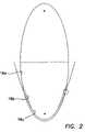
- FIG. 2is a simplified line diagram of the two dimensional cross-sectional profiles of the cross-sectional surfaces of the reflector of FIG. 1 .
- FIG. 3is a cross-sectional diagram of the ray sets of the beam pattern generated by the embodiment of FIGS. 1 and 2 .
- the upper portion of FIG. 3is a skewed projected view of the beam at the target surface to more clearly describe the overlay of the reflected energy and the direct energy of the light source. For clarity, only one side of the reflected energy is shown, which must be understood to be completed by rotating the cross-sectional pattern about the axis of symmetry of the reflector.
- FIG. 4is a cross-sectional drawing of another embodiment of the invention with the open reflector of FIG. 1 replaced by a solid molded TIR reflector.
- FIG. 5is a cross-sectional drawing of an embodiment of the invention where the TIR reflector of FIG. 4 is molded as the protective cover of the LED and incorporated in the manufacture of the LED itself.
- FIG. 6is a cross-sectional drawing of the reflector assembly of an embodiment of the invention where the reflector is derived from a transfer function and may be called a super-areal light device.
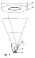
- FIG. 7is a cross-sectional diagram of the device of FIG. 6 showing a an incremental area or angular increment of the reflector and its relative contribution to the overlaid reflected beam.
- a skewed projected viewis also shown in the upper part of the figure to illustrate the increment's contribution to the overlaid reflected beam.
- FIG. 8is a cross-sectional drawing of the embodiment where of FIG. 6 where the reflector is replaced by a solid molded TIR reflector.
- FIG. 9is a cross-sectional drawing of an embodiment where the TIR reflector of FIG. 7 is molded as the protective cover of the LED and incorporated at time of manufacture of the LED.
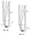
- FIG. 10is a cross-sectional drawing of the triconic reflector of the invention which is utilized to introduce energy into a fiber.
- the drawingshows the rays all being within the numerical aperture of the fiber for maximum coupling efficiency.
- FIG. 11is a cross-sectional drawing of the super-areal light of the invention coupled to a fiber.
- FIG. 12is an array of devices of the invention combined into a light fixture.
- FIG. 13is a cross sectional diagram of a reflex LED light source in a super areal light device.
- FIG. 14is a cross sectional diagram of a hybrid LED light source in a super areal light device.
- the preferred embodiment of the inventionis directed to light emitting diodes (LED) and a method of collecting and distributing the energy radiated from them with increased energy efficiency.
- LEDlight emitting diodes
- the preferred embodimentresults in energy efficiencies approximately equal to or better than 90%.
- the inventionis not limited to LED light sources, but may be employed with incandescent, plasma arc, fluorescent light sources or any type of light source now known or later devised, particularly those with similar or equal energy efficiencies.
- the term, “light”is used in its broadest sense as including the ultraviolet and infrared portions of the spectrum and that any light frequency which can be approximately modeled by optical ray tracing is contemplated was being within the scope of the invention.
- Devices utilizing the inventionwould be used in general lighting, decorative and architectural lighting, reading lights for home, airline or automobile, task lighting, flood lighting, emergency lighting, fiber optic illumination, panel backlighting, signage and other applications too numerous to mention.
- a complete listingis impossible to provide and thus it must be understood that the larger assemblies or systems in which various embodiments of the invention could be used include all applications of illumination now known or later devised.
- the various embodiments of the inventioncan also be used as the basis for or in combination with more complex optical systems with having additional optical elements and optical processing.
- the illustrated embodiments of the inventionprovide virtually complete collection efficiency of the energy radiating from an LED into a desired or directed beam. The distribution of energy in the resultant beam is controlled by design and capable of being predetermined or controlled by arbitrary design or user choice.
- the illustrated embodiments of the inventionprovide a substantial improvement over the prior art for generating a controlled, smooth beam from an LED source and utilize substantially all the energy radiating from the LED in doing so.
- a mediumsuch as through a lens, total internal reflector (TIR), across an optical interface, or reflection of light from a reflecting surface is never perfect or 100%.
- TIRtotal internal reflector
- substantially allfor the purpose of this specification and its claims shall be understood to mean all of the light generated by the light source within a frequency bandwidth of interest reduced only by inherent losses in a minimum of touches of the light, such as one or two touches from refraction or reflection, or at least that amount of loss of light intensity such that it would not be readily discernible to the unaided human eye.
- Illumination systemsgenerate beams that are collimated, like a searchlight, omni-directional; such as fluorescent tube or standard light bulb; narrow conical light patterns, such as a spot light; broad conical light patterns, such as a floodlight or some combination of these.
- the inventionhas its primary advantage in the ability to efficiently create narrow and broad conical light patterns from the energy radiating from the LED emitter 10 mounted on a conventional heat sink or package substrate 11 .
- the energy radiating from the LED emitter 10is segmented or partitioned into two regions or ray sets defined about the optical axis of the LED 10 , which are each treated or optically processed differently.
- energyshall be taken to mean both energy, e.g. Joules, and power or energy per unit time, e.g. Watts. It shall be assumed in the following discussion that LED 10 always has an optical axis of symmetry so that its radiation pattern is approximately symmetric about an axis within manufacturing tolerances.
- LED chips or light emitting interfacesare typically manufactured to be square or rectangular in shape and have three dimensional radiation patterns which map the shape of the light emitting interface.
- the inventionis not limited to symmetric light emitting interfaces or radiation patterns and can be modified in manner consistent with the teachings below to accommodate an arbitrarily shaped radiation pattern or light emitting interface.
- the first region or ray set 20(ray set A in FIG. 3 ) is the central conical energy radiating from the LED emitter 10 as best shown in FIG. 3 .
- the second region or ray set 22is the remainder of the nearly hemispherical distribution of energy radiating from an LED emitter 10 , which are shown collectively in FIG. 3 as the ray sets B, C and D.
- conventional LED emittersactually have a radiation distribution pattern which extends below the horizon or the 90° half angle from the normal to the light emitting interface or the polar angle.
- conventional LED emittershave a radiation distribution patterns extending down to 95-100° half angles, although the intensity of the light in these angles decreases dramatically. in the balance of this specification It will be assumed for the sake of simplicity that the radiation distribution pattern extends to the 90° half angle, but the modification necessary to include larger half angles can readily be made in a manner consistent with the teachings of the invention.
- the energy in the first region 20remains optically unmodified or untouched and is radiated directly to the target or surface to be illuminated. By not placing any optical surface in the path of light in this first region 20 , there are no losses of energy from the LED emitter 10 to the target of the beam.
- the included angle chosen for the cone of energy in this first region 20is defined as the design or system angle of the device 12 .
- the preferred embodiment of the inventionis practical for included half angles of approximately 10°-70°.
- the energy of the second region 22is modified by the surface or surfaces 16 of either a custom designed partially, multisectioned reflector 14 or a single reflector surface 16 defining a surface of rotation, which is also custom tailored or shaped.
- the reflector surface 16is divided into three zones 16 a , 16 b and 16 c as best depicted in FIG. 2 .
- a unique, arbitrarily designer controlled distribution of energy in the beamcan be defined.
- the energy of the beam generated by the reflector 14 from the second region 22is added to the energy of the direct light from source 10 of the first region 20 .
- the only loss of energy in the systemis the surface loss of the portion of the LED energy that is touched or modified by the reflector 14 from the second region or ray sets 22 .
- the remainder of the emitted energy from the LED 10is distributed into the intended beam, resulting in almost 100% collection and almost 100% distribution of the light.
- the illustrated zones 16 a , 16 b and 16 c of the reflector 14can be described using the two dimensional collection angles or half angles derived between a ray line perpendicular to the emitter 10 passing through its center (also called the normal ray or optical axis 18 of emitter 10 ) and another ray line passing also through the center but inclined at an angle from the original perpendicular line or normal.
- the first reflector zone 16 afarthest from the emitter 10 (giving rise to ray set B in FIG.
- first zone 16 awill be focused at or near the second focus of the ellipse.
- the farthest point on reflector 14 from the emitter 10 on the two dimensional profile of the first zone 16 ais coincident with the ray line described above as being the half-angle of the intended or system beam. In the preferred embodiment of the invention, this point is nearly perpendicular to the mid point between two foci of an ellipse.
- the reflector 14closest to the emitter 10 , can also be defined as a surface of revolution about the axis 18 of the system whose two dimensional-profile could be a conic, generally a parabola, with its focus placed near the center of the emitter 10 .
- zone 16 c of reflector 14is approximately collimated and parallel to optical axis 18 .
- the parabolic profilewould be placed in a position so that the sagitta of the parabola or the distance from upper limits of the parabolic surface or zone 16 c to the chord across the upper limits is inside the ellipse of the first zone 16 a of the reflector 14 .
- the collection angle of zone 16 c of the reflector 14is also chosen based on the parameters of the design of the system, such as the depth and aperture size of reflector 14 , and the distance from emitter 10 to the illumined surface.
- a third zone 16 b of the reflector 14(giving rise to ray set D in FIG. 3 ) is a segment of a cone, whose cross-section is a line that extends between the endpoints of the two dimensional-profiles of the farthest and nearest 16 a and 16 c respectively.
- zone 16 bis a right circular conic section which transitions between zones 16 a and 16 c .
- This cross-section profile of zone 16 bcould also be any shape of curve that connects the zones 16 a and 16 b described above and which is optionally tangent or approximately tangent to the respective endpoints of zones 16 a and 16 b , i.e. provides for a smooth transition between zone 16 a and zone 16 c or at least visually appears to be smooth to the unaided human eye.
- the illustrated embodiment of the inventionanticipates two or more defined zones 16 a and 16 c and/or the addition of facets in the cross-sections and/or the surface of revolution or other means to provide integration, or homogenization of the resultant composite beam.
- the illustrated embodiments of the invention described abovecould be loosely referred to as triconic devices 12 , but it must be understood that only two of the zones 16 a and 16 b need be in the shape of conic sections.
- a plurality of devices 12 incorporating the inventionmay be assembled into arrays and/or included in an assembly of optical elements to provide additional functionality according to conventional design principles.
- Arrays of two or more units of the inventionmay include devices that are individually optimized for a particular set of design criteria. These arrays would be used for backlights for LCD monitors and other panel displays. These arrays could be utilized for backlighting of signs.
- the preferred embodimentscould be constructed as either a reflector, a TIR optic that can optionally be attached onto the LED package, or an OEM package replacement optic which is integrally made with the LED package.
- reflector 14is designed using a transfer function to map the three dimensional energy distribution of the LED emitter 10 to the two dimensional energy pattern desired for the output beam of a device 12 of the invention.
- emitter 10has an axis of symmetry so that its energy distribution pattern can be usefully described by only referencing two dimensional half angles or the polar angle of the energy distribution pattern.
- the transfer function of the inventioncan be appropriately modified in a manner consistent with the teachings of the invention to accommodate such irregularity.
- the transfer functionresults in each point of a surface of revolution defining the surface of reflector 14 having surface normals about which the light energy is reflected across or parallel to the centerline 18 of the device 12 and which reflecting surface distributes the light energy into a reflected beam that overlays or partially overlays the directly radiated energy from light source 10 which does not reflect off the reflector 14 .
- the reflected beam and hence the composite beamwill have an energy or intensity distribution which is determined by arbitrary user definition or selection.
- This preferred embodiment of the inventionis determined by the following method which is preferably performed in a computer (not shown).
- the system half-angle, reflector aperture diameter and distance from the light source 10 to the intended targetare determined based on selected design criteria. This establishes the outermost point on the rim of the reflector 14 . All the energy of the LED 10 that is narrower in angle from the centerline 18 than that determined by the design criteria is radiated directly to the intended target surface. The distribution of energy in the target zone is calculated and utilized in the reflector surface point calculations that follow. If the target is a two dimensional flat surface and if a standard Lambertian LED 10 is used, the energy distribution will fall off nearly as the cosine of the angle off of the centerline 18 of the system.
- the system angle and source-to-target distancedefine a starting radius for the energy distribution pattern on the target.
- the pattern of the distribution of the remaining energy radiated from the source 10can be modified or not, based again on selected design criteria.
- the distribution pattern on the target surfaceis intended to be nearly flat in the reflected beam. This is accomplished by dividing the radiated LED energy distribution into small angular increments, ⁇ , and first summing the energy content of the directly radiated beam into the forward central solid angle of the system. The energy content of the directly radiated beam is subtracted from the total energy radiated from the LED 10 and the remainder is used for calculating the reflector points or segments. The energy content of each of the angular increments, ⁇ , is normalized across the angles of the remaining LED energy, which will be reflected.
- the energy in the first thirty degreesis subtracted from the total energy radiated by the LED 10 .
- the remaining 70° of angle, the peripheral solid angle of LED 10is normalized by its percent of the total remaining energy.
- the area of the targetis calculated.
- the portion of the remaining energy incident on the incremental angle, ⁇ 1is mapped onto a corresponding incremental area of the target surface 28 , which is the illustrated embodiment is a circular ring 24 as best shown in FIG. 7 .
- the source-to-target magnification ratiois ignored. It can be calculated and considered and it is the intention of the invention to allow for this calculation, however, it is instructive to describe the simpler case.
- Each angular increment, ⁇ iis characterized by a ratio of the energy reflected from that angular increment, ⁇ i , to the total energy reflected.
- the light reflected from each angular increment, ⁇ i , to a corresponding incremental area on target surface 28is also characterized by the same energy ratio in the target surface 28 .
- whatever energy distribution is incident on the reflector surfaceis faithfully reproduced on the target surface 28 less inherent reflector losses. It is also entirely within the scope of the invention to provide uniform reflected illumination of the target surface 28 , or as described below an energy distribution of the reflected energy onto the target surface 28 which is arbitrarily different from the energy distribution on the reflector surface according to design control.
- This ratio equality in the illustrated embodimentthus defines an inner radius of ring 24 corresponding to the incremental angle, ⁇ 1 , of the reflector 14 .
- the normal to the corresponding incremental area of the reflector 14can be derived from and is the bisector of the angle between the incoming ray from the source 10 to a center point of the incremental area of the reflector 14 and the outgoing reflected ray from the center point to the center of ring 24 on the target.
- points other than the centers of the incremental area and the ring 24can be equivalently employed.
- calculationscould be one edge of the incremental area to a corresponding edge of the ring 24 .
- the corresponding incremental reflecting areais thus defined by its spatial position relative to source 10 and the normal of its surface at the point of interest. Its end point on the reflector surface is the starting point for the next incremental area corresponding to angle, ⁇ 2 .
- the calculations for the reflector pointscontinue until all the incremental areas corresponding to the angular increments, ⁇ i , are defined.
- What resultsis a numerical table of calculated data points corresponding to the starting and ending points for each incremental area which serve to define the reflector surface.
- an analytical functiondefining a smooth curve or surface in space on which those points will lye, namely a polynomial series with numerically calculated coefficients. Numerous computer curve tracing utility programs exist which provide for this capability. This portion of the method could thus be rendered into a computerized analytical function, if desired or applicable and the entire reflector surface then defined by the analytical function.
- Some preferred embodimentscan simply be calculated as described above. Others would utilize modifying calculations to the energy distribution of the angular increments. As an example, the near cosine fall off of the directly radiated beam, a factor could be included in the calculations for the overlaid, reflected beam to compensate for the fall off and smooth it out. In other words, the reflected beam could be more heavily weighted or concentrated in the region of the fall off of the directly radiated beam to smooth or null it out.
- compensationmight be performed by adding a multiplier, ratio, defined curve offset, sag or other compensation in the areal distribution of the overlaid-reflected beam onto the target surface, which compensation is back-calculated into the distribution of the energy in the reflected beam as determined by the two dimensional reflector profile.
- the reflected beam energy distribution derived from the two dimensional profile of the reflectorcould be replaced by a reflected beam energy distribution derived from a three dimensional reflector surface.
- the angular incrementsare given by an angle pair, ( ⁇ i , ⁇ i ) and the corresponding incremental areas or zones are not surfaces of revolution as assumed above, but are areal patches on the reflector surface.
- the preferred embodimentprovides a smooth, flat beam profile at the target surface that when multiple units of the invention are utilized in an array.
- the arrayprovides an extremely smooth total distribution without ‘hot spots’ associated with the prior art.
- the resultis a smooth, highly efficient and effective beam that in most applications does not require any diffuser or additional optical treatment.
- the preferred embodimentscould be constructed as reflectors, a TIR optic that can optionally be attached onto the LED package or an OEM package replacement optic.
- FIG. 4is a cross-sectional diagram of a device 12 in which reflector 14 is replaced by a total internal reflector 30 which has an exterior surface 40 provided with the three defined zone shapes of FIG. 1 , namely either a parabola, a straight cone, and ellipse or a parabola, transition zone, and ellipse.
- TIR 30is also provided with a basal reflective treatment or coating 32 to insure that internal reflection is also provided at what might otherwise be unfavorable angles for internal reflection within TIR 30 .
- Emitter 10is provided in a conventional LED package 34 , which normally provides no refraction of the light from emitter 10 .
- the interior space 36 between emitter 10 and package 34is filled with an optical gel or material 38 which provides index matching so that there are no optical discontinuities between emitter 10 and the surface of package 34 .
- An optical matching adhesiveis also provided between the surface of package 34 and the conforming surface of TIR reflector 30 attached on it, so that the only optical events encountered by light rays radiated from emitter 10 are total internal reflection from surface 40 or coating 32 , and refraction through aperture interface 42 .
- FIG. 5is a cross-sectional diagram of a device 12 similar to that of FIG. 4 in which TIR reflector 30 is integrally made with the manufacture of LED package 34 as an OEM manufacture.
- FIG. 6is a cross-sectional diagram of a device 12 which is provided with the super-areal shaped reflector 14 as determined by the transfer function described above.
- the emitter 10is provided with conventional LED packaging 34 as described above in connection with FIG. 4 .
- FIG. 8is a cross-sectional diagram of a device 12 which a TIR reflector 44 has been substituted for the super-areal shaped reflector 14 of FIG. 6 and which is provided a super-areal shaped exterior surface 46 as derived from the transfer function described above in connection with FIG. 7 .
- FIG. 9is a cross-sectional diagram of a device 12 similar to that of FIG. 8 in which TIR reflector 44 is integrally made with the manufacture of LED package 34 as an OEM manufacture.
- FIG. 10is a cross-sectional diagram of a device 12 of FIG. 1 , 4 or 5 coupled to the input of a fiber 50 .
- the fiber 50may be a hollow, solid, single or stranded.
- FIG. 10shows a single hollow fiber 50 for the purposes of simplicity.
- FIG. 11is a cross-sectional diagram of a device 12 of FIG. 6 , 8 or 9 coupled to the input of a fiber 50 .
- the fiber 50may be a hollow, solid, single or stranded.
- FIG. 9shows a single hollow fiber 50 for the purposes of simplicity.
- FIG. 12is a perspective view of a light fixture 52 which includes an array or plurality of devices 12 as shown in any one of the FIGS. 1-9 .
- the elements of fixture 52are conventional and may include additional optical elements.
- the design of the arraycan be configured to any configuration or arrangement of light arrays now known or later devised.
- FIG. 13is a cross-sectional diagram of a device 12 , which is called a reflex light source in this specification, which reflector 14 has been designed according to the teachings connected with FIG. 7 and the super areal light. Further detail on the reflex device 12 is provided in U.S. patent application Ser. No. 10/361,137 and entitled Method and Apparatus for the Efficient Collection and Distribution of Light for Illumination, which is incorporated herein by reference. Any of the reflectors of FIGS. 6-9 could be employed in the reflex device 12 of FIG. 13 .
- Emitter 10is contained within a conventional LED package 34 , positioned on the optical axis of reflector 14 and turned to face the base of reflector 14 .
- the reflector 14has a defined shape derived from the transfer function, which has as inputs: the three dimensional radiation pattern of the light source; beam parameters, such as light source-to-reflector distance, reflector-to-surface distance, and beam diameter; system parameters of the reflector 14 such as reflector size and aperture size of the reflector 14 ; and a desired energy distribution on the surface.
- the transfer functionhas as outputs: an amount of radiated energy propagating through the aperture of the reflector 14 ; and a calculated position and orientation of each point on the reflector 14 as a function of angle needed to provide the desired energy distribution on the surface, which calculation defines the shape of the reflector 14 necessary to provide a reflected energy pattern.
- the transfer functionconfigures the shape of the reflector 14 to send reflected light from a first portion of the reflector 14 extending from the base of the reflector 14 to a predetermined demarcation on the reflector 14 to a first portion of the energy distribution on the surface which is arbitrarily designer selected, such as an outer portion of the illumined surface 28 so that the heat sink 54 and light source 10 are avoided and the amount of figure losses of device 12 minimized.
- the transfer functionconfigures the shape of the reflector 14 to send reflected light from a second portion of the reflector 14 extending from the predetermined demarcation on the reflector 14 to the aperture of the reflector 14 to a second portion of the energy distribution on the surface which is arbitrarily designer selected, such as an inner portion of the illumined surface 28 .
- the predetermined demarcation on the reflector 14is chosen in the illustrated embodiment at a position such that light reflecting from the second portion of the reflector 14 is not generally obstructed by the heat sink 54 and light source 10 in any case.
- light reflecting from the first portion of the reflector 14is in essence directed around the heat sink 54 and light source 10 to the surface 28 .
- light from the first and second portions of the reflector 14can be directed to any portion of surface 28 .
- the reflex device 12 of FIG. 13could be alternatively embodied with a triconic reflector of the type as shown in FIGS. 1-5 .
- FIG. 14is a cross-sectional drawing of an embodiment, call in this specification a hybrid LED light source, where a lens 56 is disposed longitudinally forward of reflector 14 of the type described in connection with FIGS. 6-9 for allowing radiated energy directly from the light source 10 to propagate through the lens 56 to the illuminated surface 28 to provide a directed energy distribution pattern on the illuminated surface 28 .
- the reflector 14again has a surface and defined shape derived from a transfer function as described above, but which may also include part of the inputs lens parameters, and as part of the outputs an amount of directed radiated energy propagating through the lens 56 ; a remainder of the total available radiated energy from the light source 10 less the energy of the directed light propagating to the illuminated surface 28 through the lens 56 ; and a calculated position and orientation of each point on the surface of the reflector 14 as a function of angle needed to provide the desired composite energy distribution on the illuminated surface 28 .
- the calculationdefines the shape of the reflector 14 necessary to provide a reflected energy pattern to overlay the directed energy pattern to form the designer controlled composite energy distribution on the surface 28 .
- Further detail on the hybrid device 12is provided in U.S.
- hybrid device 12 of FIG. 14could be alternatively embodied with a triconic reflector of the type as shown in FIGS. 1-5 .
Landscapes
- Physics & Mathematics (AREA)
- Engineering & Computer Science (AREA)
- General Engineering & Computer Science (AREA)
- Optics & Photonics (AREA)
- General Physics & Mathematics (AREA)
- Microelectronics & Electronic Packaging (AREA)
- Non-Portable Lighting Devices Or Systems Thereof (AREA)
- Optical Elements Other Than Lenses (AREA)
- Led Device Packages (AREA)
Abstract
Description

Claims (3)
Priority Applications (1)
| Application Number | Priority Date | Filing Date | Title |
|---|---|---|---|
| US12/210,114US7591570B2 (en) | 2004-03-30 | 2008-09-12 | Apparatus and method for improved illumination area fill |
Applications Claiming Priority (4)
| Application Number | Priority Date | Filing Date | Title |
|---|---|---|---|
| US55819904P | 2004-03-30 | 2004-03-30 | |
| US11/093,998US7945657B1 (en) | 2005-03-30 | 2005-03-30 | System and method for emulating input/output performance of an application |
| US11/633,877US7438447B2 (en) | 2004-03-30 | 2006-12-04 | Apparatus and method for improved illumination area fill |
| US12/210,114US7591570B2 (en) | 2004-03-30 | 2008-09-12 | Apparatus and method for improved illumination area fill |
Related Parent Applications (1)
| Application Number | Title | Priority Date | Filing Date |
|---|---|---|---|
| US11/633,877DivisionUS7438447B2 (en) | 2004-03-30 | 2006-12-04 | Apparatus and method for improved illumination area fill |
Publications (2)
| Publication Number | Publication Date |
|---|---|
| US20090043544A1 US20090043544A1 (en) | 2009-02-12 |
| US7591570B2true US7591570B2 (en) | 2009-09-22 |
Family
ID=35064336
Family Applications (4)
| Application Number | Title | Priority Date | Filing Date |
|---|---|---|---|
| US11/093,988Expired - LifetimeUS7172319B2 (en) | 2004-03-30 | 2005-03-30 | Apparatus and method for improved illumination area fill |
| US11/633,877Expired - LifetimeUS7438447B2 (en) | 2004-03-30 | 2006-12-04 | Apparatus and method for improved illumination area fill |
| US12/210,114Expired - LifetimeUS7591570B2 (en) | 2004-03-30 | 2008-09-12 | Apparatus and method for improved illumination area fill |
| US12/210,183ActiveUS7581855B2 (en) | 2004-03-30 | 2008-09-13 | Apparatus and method for improved illumination area fill |
Family Applications Before (2)
| Application Number | Title | Priority Date | Filing Date |
|---|---|---|---|
| US11/093,988Expired - LifetimeUS7172319B2 (en) | 2004-03-30 | 2005-03-30 | Apparatus and method for improved illumination area fill |
| US11/633,877Expired - LifetimeUS7438447B2 (en) | 2004-03-30 | 2006-12-04 | Apparatus and method for improved illumination area fill |
Family Applications After (1)
| Application Number | Title | Priority Date | Filing Date |
|---|---|---|---|
| US12/210,183ActiveUS7581855B2 (en) | 2004-03-30 | 2008-09-13 | Apparatus and method for improved illumination area fill |
Country Status (5)
| Country | Link |
|---|---|
| US (4) | US7172319B2 (en) |
| EP (2) | EP1753996B1 (en) |
| CN (2) | CN101619834B (en) |
| AT (1) | ATE514898T1 (en) |
| WO (1) | WO2005094378A2 (en) |
Cited By (5)
| Publication number | Priority date | Publication date | Assignee | Title |
|---|---|---|---|---|
| US20110044025A1 (en)* | 2009-08-24 | 2011-02-24 | Phoenix Electric Co., Ltd. | Light emitting device |
| US20120092864A1 (en)* | 2009-06-16 | 2012-04-19 | Koninklijke Philips Electronics N.V. | Illumination system for spot illumination with reduced symmetry |
| US20120240976A1 (en)* | 2011-03-25 | 2012-09-27 | Hung-Pin Kuo | Light assembly |
| USD673307S1 (en) | 2011-05-12 | 2012-12-25 | Cooper Technologies Company | Light bar |
| US9161419B2 (en) | 2012-07-02 | 2015-10-13 | International Business Machines Corporation | Intelligent and coordinated lighting of a lighting device |
Families Citing this family (136)
| Publication number | Priority date | Publication date | Assignee | Title |
|---|---|---|---|---|
| CA2460205C (en)* | 2001-12-31 | 2005-05-03 | R J Doran & Co Ltd. | Led inspection lamp and led spot light |
| US7182597B2 (en)* | 2002-08-08 | 2007-02-27 | Kerr Corporation | Curing light instrument |
| WO2004114003A1 (en)* | 2003-06-24 | 2004-12-29 | Koninklijke Philips Electronics, N.V. | Method and apparatus for recycling reflected light in optical systems as e.g. projection display |
| CA2634475C (en)* | 2003-07-07 | 2014-05-20 | Brasscorp Limited | Led-based inspection lamp with improved collimation optics |
| US7798667B2 (en)* | 2003-07-07 | 2010-09-21 | Brasscorp Limited | LED spotlight |
| US7553051B2 (en) | 2004-03-18 | 2009-06-30 | Brasscorp Limited | LED work light |
| US8562184B2 (en)* | 2004-03-18 | 2013-10-22 | Brasscorp Limited | LED work light |
| US7172319B2 (en)* | 2004-03-30 | 2007-02-06 | Illumination Management Solutions, Inc. | Apparatus and method for improved illumination area fill |
| DE202004011015U1 (en)* | 2004-07-14 | 2004-11-11 | Tridonic Optoelectronics Gmbh | LED spotlight with funnel-shaped lens |
| US20060134576A1 (en)* | 2004-12-21 | 2006-06-22 | John West | Dental illumination device with single or multiple total internal reflectors (TIR) |
| KR20070099647A (en)* | 2005-01-14 | 2007-10-09 | 코닌클리즈케 필립스 일렉트로닉스 엔.브이. | Variable reflector unit |
| KR101109592B1 (en)* | 2005-04-25 | 2012-01-31 | 삼성전자주식회사 | Light source module and image projector using the same |
| US20080025013A1 (en)* | 2005-05-02 | 2008-01-31 | Pelton & Crane | Led-powered dental operatory light |
| US8016470B2 (en) | 2007-10-05 | 2011-09-13 | Dental Equipment, Llc | LED-based dental exam lamp with variable chromaticity |
| US8459852B2 (en)* | 2007-10-05 | 2013-06-11 | Dental Equipment, Llc | LED-based dental exam lamp |
| US8079743B2 (en)* | 2005-06-28 | 2011-12-20 | Lighting Science Group Corporation | Display backlight with improved light coupling and mixing |
| JP2007041546A (en)* | 2005-06-29 | 2007-02-15 | Sanyo Electric Co Ltd | Optical device and projection type video display including optical device |
| US7789536B2 (en)* | 2005-11-21 | 2010-09-07 | Koninklijke Philips Electronics N.V. | Lighting device |
| US7306351B2 (en)* | 2005-12-14 | 2007-12-11 | Chung Yuan Christian University | Lens for side emitting LED device |
| US7670030B2 (en)* | 2006-02-13 | 2010-03-02 | Brasscorp Limited | Reflectors, reflector/LED combinations, and lamps having the same |
| US8434912B2 (en)* | 2006-02-27 | 2013-05-07 | Illumination Management Solutions, Inc. | LED device for wide beam generation |
| US7674018B2 (en)* | 2006-02-27 | 2010-03-09 | Illumination Management Solutions Inc. | LED device for wide beam generation |
| US8299903B2 (en)* | 2006-03-23 | 2012-10-30 | Edward H Haase | Screw-in LED light and sound bulb |
| US7795632B2 (en)* | 2006-06-26 | 2010-09-14 | Osram Sylvania Inc. | Light emitting diode with direct view optic |
| DE102006032249B4 (en) | 2006-07-12 | 2013-11-07 | Airbus Operations Gmbh | Invisible emergency lighting for an aircraft cabin |
| CA2884517C (en)* | 2006-12-24 | 2017-01-24 | Brasscorp Limited | Led lamps including led work lights |
| RU2456503C2 (en)* | 2007-04-05 | 2012-07-20 | Конинклейке Филипс Электроникс Н.В. | Light beam former |
| US20080260328A1 (en)* | 2007-04-20 | 2008-10-23 | 3M Innovative Properties Company | Led light extraction bar and injection optic for thin lightguide |
| US20080260329A1 (en)* | 2007-04-20 | 2008-10-23 | 3M Innovative Properties Company | Lightguides having curved light injectors |
| US8430538B2 (en)* | 2007-05-21 | 2013-04-30 | Illumination Management Solutions, Inc. | LED device for wide beam generation and method of making the same |
| EP1998102B8 (en)* | 2007-05-31 | 2018-03-21 | OSRAM Opto Semiconductors GmbH | Light source |
| CN101755165A (en)* | 2007-06-05 | 2010-06-23 | 皇家飞利浦电子股份有限公司 | Illuminator, collimater and spotlight |
| DE602008006413D1 (en) | 2007-08-01 | 2011-06-01 | Koninkl Philips Electronics Nv | COLLIMATING MODULE AND EQUIPMENT FOR ZERO OVERFILL LIGHTING APPLICATIONS WITH BEAM WIDTH CONTROL |
| US20090059573A1 (en)* | 2007-08-29 | 2009-03-05 | James Bears | Solid-state lighting device |
| TW200931683A (en)* | 2007-09-20 | 2009-07-16 | Koninkl Philips Electronics Nv | LED package |
| TW200921007A (en)* | 2007-11-15 | 2009-05-16 | Prodisc Technology Inc | An optics for reshaping the light shape and a light module for the same |
| US20090140048A1 (en)* | 2007-11-30 | 2009-06-04 | Symbol Technologies, Inc. | CPC Illumination Apparatus for an Imaging-Based Bar Code Reader |
| US8042961B2 (en)* | 2007-12-02 | 2011-10-25 | Andrew Massara | Audio lamp |
| US8322881B1 (en) | 2007-12-21 | 2012-12-04 | Appalachian Lighting Systems, Inc. | Lighting fixture |
| TWM351317U (en) | 2007-12-24 | 2009-02-21 | Prodisc Technology Inc | Optical component and light source module thereof |
| DE102008005120A1 (en)* | 2008-01-18 | 2009-09-10 | Osram Gesellschaft mit beschränkter Haftung | LED module with a lens |
| DE102009012273B4 (en) | 2008-03-14 | 2021-09-23 | Leuze Electronic Gmbh & Co. Kg | Optical sensor |
| CN101532638A (en)* | 2008-03-14 | 2009-09-16 | 鸿富锦精密工业(深圳)有限公司 | Light-emitting diode light source module |
| DE102008016496A1 (en)* | 2008-03-31 | 2009-10-01 | Zumtobel Lighting Gmbh | Luminaire with punctiform light source and asymmetrical light emission characteristic |
| US20090268453A1 (en)* | 2008-04-24 | 2009-10-29 | King Luminarie Co., Inc. | LED baffle assembly |
| JP5542130B2 (en)* | 2008-06-11 | 2014-07-09 | コーニンクレッカ フィリップス エヌ ヴェ | Light-emitting system that produces a beam with adjustable width |
| US8002435B2 (en)* | 2008-06-13 | 2011-08-23 | Philips Electronics Ltd Philips Electronique Ltee | Orientable lens for an LED fixture |
| US7766509B1 (en) | 2008-06-13 | 2010-08-03 | Lumec Inc. | Orientable lens for an LED fixture |
| CN103459919B (en)* | 2008-08-14 | 2016-10-26 | 库帕技术公司 | For biasing the LED device that angle pencil of ray generates |
| US7874703B2 (en)* | 2008-08-28 | 2011-01-25 | Dialight Corporation | Total internal reflection lens with base |
| US8664858B2 (en) | 2008-09-05 | 2014-03-04 | Martin Professional A/S | Light fixture with an electrodeless plasma source |
| US8075162B2 (en)* | 2008-09-12 | 2011-12-13 | Light Prescriptions Innovators, Llc | Zoom luminaire with compact non-imaging lens-mirror optics |
| CN101660710B (en)* | 2008-09-25 | 2011-03-16 | 海洋王照明科技股份有限公司 | Tunnel lamp reflector |
| US8226262B2 (en)* | 2008-09-30 | 2012-07-24 | Reflexite Corporation | TIRing condensing element and methods thereof |
| US7980727B2 (en) | 2008-10-07 | 2011-07-19 | Reflexite Corporation | Monolithic tiring condensing arrays and methods thereof |
| US8342709B2 (en)* | 2008-10-24 | 2013-01-01 | Hubbell Incorporated | Light emitting diode module, and light fixture and method of illumination utilizing the same |
| JP5524470B2 (en)* | 2008-11-12 | 2014-06-18 | 株式会社小糸製作所 | Vehicle lamp unit and vehicle lamp |
| MX2011005753A (en)* | 2008-12-03 | 2011-11-18 | Illumination Man Solutions Inc | A SPARE LED LAMP AND A METHOD OF REPLACEMENT OF PRE-EXISTING LUMINAIRES WITH LED LUMINARY ASSEMBLY. |
| JP5379166B2 (en)* | 2009-01-20 | 2013-12-25 | パナソニック株式会社 | Lighting device |
| US8246212B2 (en)* | 2009-01-30 | 2012-08-21 | Koninklijke Philips Electronics N.V. | LED optical assembly |
| US8576406B1 (en) | 2009-02-25 | 2013-11-05 | Physical Optics Corporation | Luminaire illumination system and method |
| AU2010201102B2 (en)* | 2009-03-19 | 2013-06-27 | Gamma Illumination Pty Limited | Light Assembly for Domestic and Industrial Enviroments |
| US7959322B2 (en)* | 2009-04-24 | 2011-06-14 | Whelen Engineering Company, Inc. | Optical system for LED array |
| US20100302790A1 (en)* | 2009-05-27 | 2010-12-02 | Etronic Team Co., Ltd. | Led luminaire and method for fabricating the same |
| US8186852B2 (en)* | 2009-06-24 | 2012-05-29 | Elumigen Llc | Opto-thermal solution for multi-utility solid state lighting device using conic section geometries |
| US8097894B2 (en)* | 2009-07-23 | 2012-01-17 | Koninklijke Philips Electronics N.V. | LED with molded reflective sidewall coating |
| US8358081B2 (en)* | 2009-08-21 | 2013-01-22 | Teledyne Technologies Incorporated | Lamp assembly |
| US8066417B2 (en)* | 2009-08-28 | 2011-11-29 | General Electric Company | Light emitting diode-light guide coupling apparatus |
| JP5516854B2 (en)* | 2009-10-08 | 2014-06-11 | スタンレー電気株式会社 | Vehicle lighting |
| US8545049B2 (en) | 2009-11-25 | 2013-10-01 | Cooper Technologies Company | Systems, methods, and devices for sealing LED light sources in a light module |
| DE102010014520A1 (en)* | 2010-04-09 | 2011-10-13 | Christian Bartenbach | lamp |
| CN101858566B (en)* | 2010-04-21 | 2012-02-08 | 刘姝 | Light source reflector used in backlight component and backlight component thereof |
| US8388198B2 (en) | 2010-09-01 | 2013-03-05 | Illumination Management Solutions, Inc. | Device and apparatus for efficient collection and re-direction of emitted radiation |
| US8534901B2 (en) | 2010-09-13 | 2013-09-17 | Teledyne Reynolds, Inc. | Collimating waveguide apparatus and method |
| US8403530B2 (en) | 2010-09-21 | 2013-03-26 | Honeywell International Inc. | LED spotlight including elliptical and parabolic reflectors |
| CN102121661B (en)* | 2010-12-20 | 2013-05-29 | 中国商用飞机有限责任公司 | A navigation light for navigation light's reflecting surface cover and use this reflecting surface cover |
| US9052086B2 (en) | 2011-02-28 | 2015-06-09 | Cooper Technologies Company | Method and system for managing light from a light emitting diode |
| US9140430B2 (en) | 2011-02-28 | 2015-09-22 | Cooper Technologies Company | Method and system for managing light from a light emitting diode |
| US8608328B2 (en)* | 2011-05-06 | 2013-12-17 | Teledyne Technologies Incorporated | Light source with secondary emitter conversion element |
| CN102182980A (en)* | 2011-05-30 | 2011-09-14 | 侯立新 | Light emitting diode (LED) reflective cup |
| US8777455B2 (en) | 2011-06-23 | 2014-07-15 | Cree, Inc. | Retroreflective, multi-element design for a solid state directional lamp |
| US8757840B2 (en) | 2011-06-23 | 2014-06-24 | Cree, Inc. | Solid state retroreflective directional lamp |
| USD696436S1 (en) | 2011-06-23 | 2013-12-24 | Cree, Inc. | Solid state directional lamp |
| US8616724B2 (en)* | 2011-06-23 | 2013-12-31 | Cree, Inc. | Solid state directional lamp including retroreflective, multi-element directional lamp optic |
| US8777463B2 (en) | 2011-06-23 | 2014-07-15 | Cree, Inc. | Hybrid solid state emitter printed circuit board for use in a solid state directional lamp |
| WO2013009221A2 (en)* | 2011-07-14 | 2013-01-17 | Gorlinskiy Bronislav Vladislavovich | Light-emitting diode lamp |
| US9347642B2 (en) | 2011-09-07 | 2016-05-24 | Terralux, Inc. | Faceted optics for illumination devices |
| US8449159B2 (en) | 2011-10-18 | 2013-05-28 | Lawrence M. Rice | Combination optics light emitting diode landing light |
| US20130099263A1 (en)* | 2011-10-20 | 2013-04-25 | Gregory Lee Heacock | Full spectrum led light source |
| DE202011052125U1 (en)* | 2011-11-28 | 2012-12-04 | BÄ*RO GmbH & Co. KG | Luminaire with a reflector and reflector arrangement |
| ITMI20120488A1 (en) | 2012-03-27 | 2013-09-28 | Fael Spa | PARAELLISSOIDAL AND BIELLISSOIDAL REFLECTORS ROTATIONAL ASYMMETRICS FOR LIGHTING SYSTEMS. |
| CN103453415B (en)* | 2012-05-29 | 2017-12-12 | 深圳拓邦新能源技术有限公司 | Daytime running lamps |
| USD686773S1 (en)* | 2012-07-31 | 2013-07-23 | Xicato, Inc. | Narrow beam LED module optic |
| US20140063792A1 (en) | 2012-08-30 | 2014-03-06 | Juno Manufacturing, LLC | Hyperbolic Ceiling-Reflector For Directional Light Sources |
| US9822948B2 (en)* | 2012-09-13 | 2017-11-21 | Quarkstar Llc | Solid state illumination devices including spatially-extended light sources and reflectors |
| US9080739B1 (en) | 2012-09-14 | 2015-07-14 | Cooper Technologies Company | System for producing a slender illumination pattern from a light emitting diode |
| US9470406B2 (en) | 2012-09-24 | 2016-10-18 | Terralux, Inc. | Variable-beam light source and related methods |
| US8430536B1 (en) | 2012-10-01 | 2013-04-30 | Zumtobel Lighting Inc. | LED lighting system including TIR optic |
| DE202012009801U1 (en)* | 2012-10-15 | 2012-12-18 | Lts Licht & Leuchten Gmbh | Luminaire and lighting device for a luminaire |
| US9200765B1 (en) | 2012-11-20 | 2015-12-01 | Cooper Technologies Company | Method and system for redirecting light emitted from a light emitting diode |
| US20140146543A1 (en)* | 2012-11-26 | 2014-05-29 | Magic Lighting Optics | Outdoor lighting device |
| CN103899941A (en)* | 2012-12-29 | 2014-07-02 | 欧普照明股份有限公司 | Lighting lamp |
| US9565782B2 (en) | 2013-02-15 | 2017-02-07 | Ecosense Lighting Inc. | Field replaceable power supply cartridge |
| USD717479S1 (en) | 2013-02-21 | 2014-11-11 | 4S Industries, Inc. | LED light bar |
| US10485066B2 (en) | 2013-07-09 | 2019-11-19 | Ledvance Llc | Lamp with variable-beam output by discretely activating LED light sources |
| USD707876S1 (en) | 2013-10-07 | 2014-06-24 | Xicato, Inc. | Narrow beam LED module optic |
| CN103527954B (en)* | 2013-10-22 | 2015-07-08 | 深圳市中电照明股份有限公司 | An LED projection light source |
| CN104676412A (en)* | 2013-11-29 | 2015-06-03 | 海洋王(东莞)照明科技有限公司 | Illumination and signal dual-purpose lamp |
| FR3018363B1 (en)* | 2014-03-07 | 2016-03-04 | Thales Sa | LIGHT GUIDE FOR SOURCE OF LIGHT PONCTUELLE AND LIGHTING DEVICE THEREFOR |
| US9523480B2 (en) | 2014-04-05 | 2016-12-20 | Whelen Engineering Company, Inc. | LED illumination assembly with collimating optic |
| US10352529B2 (en) | 2014-04-05 | 2019-07-16 | Whelen Engineering Company, Inc. | Collimating optic for LED illumination assembly having transverse slots on emission surface |
| MX359451B (en) | 2014-05-19 | 2018-09-27 | Whelen Eng | Warning light with tinted lens. |
| US12372219B2 (en)* | 2014-05-30 | 2025-07-29 | Cree Lighting Usa Llc | LED luminaire with a cavity, finned interior, and a curved outer wall extending from a surface on which the light source is mounted |
| US9829179B2 (en) | 2014-06-26 | 2017-11-28 | Phillip Walesa | Parabolic quadrant LED light fixture |
| US10072819B2 (en) | 2014-10-02 | 2018-09-11 | Ledvance Llc | Light source for uniform illumination of a surface |
| US10477636B1 (en) | 2014-10-28 | 2019-11-12 | Ecosense Lighting Inc. | Lighting systems having multiple light sources |
| US10036535B2 (en) | 2014-11-03 | 2018-07-31 | Ledvance Llc | Illumination device with adjustable curved reflector portions |
| US10405388B2 (en) | 2014-12-11 | 2019-09-03 | Ledvance Llc | Variable-beam light source with mixing chamber |
| US9869450B2 (en) | 2015-02-09 | 2018-01-16 | Ecosense Lighting Inc. | Lighting systems having a truncated parabolic- or hyperbolic-conical light reflector, or a total internal reflection lens; and having another light reflector |
| US11306897B2 (en) | 2015-02-09 | 2022-04-19 | Ecosense Lighting Inc. | Lighting systems generating partially-collimated light emissions |
| US10139078B2 (en) | 2015-02-19 | 2018-11-27 | Whelen Engineering Company, Inc. | Compact optical assembly for LED light sources |
| US9651227B2 (en) | 2015-03-03 | 2017-05-16 | Ecosense Lighting Inc. | Low-profile lighting system having pivotable lighting enclosure |
| US9651216B2 (en) | 2015-03-03 | 2017-05-16 | Ecosense Lighting Inc. | Lighting systems including asymmetric lens modules for selectable light distribution |
| US9568665B2 (en) | 2015-03-03 | 2017-02-14 | Ecosense Lighting Inc. | Lighting systems including lens modules for selectable light distribution |
| US9746159B1 (en) | 2015-03-03 | 2017-08-29 | Ecosense Lighting Inc. | Lighting system having a sealing system |
| USD785218S1 (en) | 2015-07-06 | 2017-04-25 | Ecosense Lighting Inc. | LED luminaire having a mounting system |
| USD782094S1 (en) | 2015-07-20 | 2017-03-21 | Ecosense Lighting Inc. | LED luminaire having a mounting system |
| USD782093S1 (en) | 2015-07-20 | 2017-03-21 | Ecosense Lighting Inc. | LED luminaire having a mounting system |
| US9651232B1 (en) | 2015-08-03 | 2017-05-16 | Ecosense Lighting Inc. | Lighting system having a mounting device |
| US10208914B2 (en) | 2015-09-09 | 2019-02-19 | Whelen Engineering Company, Inc. | Reflector with concentric interrupted reflecting surfaces |
| US20180023783A1 (en)* | 2016-07-23 | 2018-01-25 | JST Performance, LLC | Method and apparatus for subtending light downwardly |
| US10420177B2 (en) | 2016-12-19 | 2019-09-17 | Whelen Engineering Company, Inc. | LED illumination module with fixed optic and variable emission pattern |
| DE102018221634A1 (en)* | 2018-12-13 | 2020-06-18 | Osram Gmbh | DEVICE FOR DISinfecting A FLUID |
| US12411276B2 (en) | 2020-03-04 | 2025-09-09 | Forus Health Pvt. Ltd. | Annular light source device for fundus cameras |
| US20230161127A1 (en)* | 2020-04-15 | 2023-05-25 | CommScope Connectivity Belgium BV | Device and method for sealing cables in telecommunications enclosures |
| CN114488500B (en)* | 2022-01-25 | 2025-09-02 | 中国科学院微小卫星创新研究院 | A high-energy beam energy collection device in a vacuum environment |
Citations (87)
| Publication number | Priority date | Publication date | Assignee | Title |
|---|---|---|---|---|
| US826205A (en) | 1904-11-01 | 1906-07-17 | Samuel Groves Whitehouse | Lens for lamps. |
| US2666193A (en) | 1951-05-14 | 1954-01-12 | Pyle National Co | Self-aligning dual purpose warning headlight apparatus |
| US4101957A (en) | 1976-09-10 | 1978-07-18 | Bansun Chang | Zoom operating light |
| US4151584A (en) | 1977-03-14 | 1979-04-24 | Electro Controls Inc. | Light-collecting reflector |
| US4211955A (en) | 1978-03-02 | 1980-07-08 | Ray Stephen W | Solid state lamp |
| US4286311A (en) | 1978-04-07 | 1981-08-25 | Anthony Maglica | Flashlight |
| US4388673A (en) | 1981-06-22 | 1983-06-14 | Mag Instrument, Inc. | Variable light beam flashlight and recharging unit |
| US4392187A (en) | 1981-03-02 | 1983-07-05 | Vari-Lite, Ltd. | Computer controlled lighting system having automatically variable position, color, intensity and beam divergence |
| US4398238A (en) | 1981-12-04 | 1983-08-09 | Kel-Lite Industries, Inc. | Variable focus flashlight |
| US4500947A (en) | 1982-11-10 | 1985-02-19 | Perko, Inc. | Tri spherical lens assembly |
| US4530040A (en) | 1984-03-08 | 1985-07-16 | Rayovac Corporation | Optical focusing system |
| US4533984A (en) | 1982-09-07 | 1985-08-06 | Gatton James W | Variable-width-beam light apparatus |
| US4570208A (en) | 1982-11-26 | 1986-02-11 | Sassmannshausen Knut | Portable light, such as a flashlight, searchlight, lantern or the like and method of production thereof |
| US4577263A (en) | 1984-09-06 | 1986-03-18 | Anthony Maglica | Miniature flashlight |
| US4583153A (en) | 1984-01-24 | 1986-04-15 | Tsuyama Mfg. Co., Ltd. | Lamp |
| US4698730A (en) | 1986-08-01 | 1987-10-06 | Stanley Electric Co., Ltd. | Light-emitting diode |
| US4727289A (en) | 1985-07-22 | 1988-02-23 | Stanley Electric Co., Ltd. | LED lamp |
| US4729076A (en) | 1984-11-15 | 1988-03-01 | Tsuzawa Masami | Signal light unit having heat dissipating function |
| US4730240A (en) | 1981-12-09 | 1988-03-08 | U.S. Philips Corporation | Reflector |
| US4733337A (en) | 1986-08-15 | 1988-03-22 | Lite Tek International Corp. | Miniature flashlight |
| US4745531A (en) | 1985-05-31 | 1988-05-17 | Cameleon | Lighting device with all parameters adjustable simultaneously, in particular for use as a stage light |
| US4803605A (en) | 1987-08-04 | 1989-02-07 | Rayovac Corporation | Flashlight with a backup system |
| US4814950A (en) | 1986-12-23 | 1989-03-21 | Ichikoh Industries Limited | Automotive headlight of projector type |
| US4941070A (en) | 1986-08-13 | 1990-07-10 | Canon Kabushiki Kaisha | Flash device for a camera |
| US4959757A (en) | 1988-05-09 | 1990-09-25 | Ichikoh Industries, Ltd. | Automotive lamp assembly |
| US4962450A (en) | 1987-01-19 | 1990-10-09 | Reshetin Evgeny F | Light signalling device |
| US5060120A (en) | 1990-04-19 | 1991-10-22 | Koito Manufacturing Co., Ltd. | Variable distribution type automotive headlamp |
| US5072347A (en) | 1989-05-12 | 1991-12-10 | Brunson Robert L | Search light |
| US5072346A (en) | 1988-11-02 | 1991-12-10 | Harding David K | Light beam amplifier |
| US5103381A (en) | 1991-01-09 | 1992-04-07 | Uke Alan K | Lamp reflector system |
| US5249109A (en) | 1991-08-09 | 1993-09-28 | Intermatic Incorporated | Outdoor variable focus light fixture |
| US5268977A (en) | 1992-07-06 | 1993-12-07 | Miller Jack V | Fiber optic zoom-and-dim pin-spot luminaire |
| US5282121A (en) | 1991-04-30 | 1994-01-25 | Vari-Lite, Inc. | High intensity lighting projectors |
| US5408363A (en) | 1991-06-21 | 1995-04-18 | Kano; Tetsuhiro | Reflector and a method of generating a reflector shape |
| US5477263A (en) | 1994-05-26 | 1995-12-19 | Bell Atlantic Network Services, Inc. | Method and apparatus for video on demand with fast forward, reverse and channel pause |
| US5526248A (en) | 1994-01-11 | 1996-06-11 | Ichikoh Industries, Ltd. | Projector type headlight with color-suppression structure |
| US5528474A (en) | 1994-07-18 | 1996-06-18 | Grote Industries, Inc. | Led array vehicle lamp |
| US5577493A (en) | 1992-04-16 | 1996-11-26 | Tir Technologies, Inc. | Auxiliary lens to modify the output flux distribution of a TIR lens |
| US5618102A (en) | 1995-06-07 | 1997-04-08 | Adac Plastics, Inc. | Plasma discharge lamp |
| US5630661A (en) | 1996-02-06 | 1997-05-20 | Fox; Donald P. | Metal arc flashlight |
| US5634711A (en) | 1993-09-13 | 1997-06-03 | Kennedy; John | Portable light emitting apparatus with a semiconductor emitter array |
| US5673990A (en) | 1995-01-17 | 1997-10-07 | Robert Bosch Gmbh | Headlight |
| US5711590A (en) | 1994-12-29 | 1998-01-27 | Honda Giken Kogyo Kabushiki Kaisha | Headlight having variable light distribution |
| US5808775A (en) | 1996-03-13 | 1998-09-15 | Minolta Co., Ltd. | Laser beam scanning optical apparatus |
| US5836668A (en) | 1995-07-17 | 1998-11-17 | Koito Manufacturing Co., Ltd. | Method of forming a reflection surface of a reflection mirror of a vehicle lamp |
| US5857767A (en) | 1996-09-23 | 1999-01-12 | Relume Corporation | Thermal management system for L.E.D. arrays |
| US5897196A (en) | 1996-03-29 | 1999-04-27 | Osram Sylvania Inc. | Motor vehicle headlamp |
| US5899559A (en) | 1997-02-28 | 1999-05-04 | Hella Kg Hueck & Co. | Headlamp for vehicles |
| US5904417A (en) | 1997-08-04 | 1999-05-18 | Buhl Electric, Inc. | Light fixture with elliptical reflector and mechanical shutter dimmer |
| US5924785A (en) | 1997-05-21 | 1999-07-20 | Zhang; Lu Xin | Light source arrangement |
| US5934795A (en) | 1996-06-19 | 1999-08-10 | Radiant Imaging, Inc. | Lens design for outdoor sign |
| US5954428A (en) | 1996-09-26 | 1999-09-21 | Hella Kg Hueck & Co. | Vehicle headlight |
| US5971569A (en) | 1997-06-11 | 1999-10-26 | Steris Corporation | Surgical light with stacked elliptical reflector |
| US5986779A (en) | 1995-08-18 | 1999-11-16 | Matsushita Electric Industrial Co., Ltd. | Multiple focus lens, an optical head apparatus and an optical information recording-reproducing apparatus |
| US6007210A (en) | 1995-09-12 | 1999-12-28 | Denso Corporation | Discharge lamp device having a light distribution compound lens |
| US6045240A (en) | 1996-06-27 | 2000-04-04 | Relume Corporation | LED lamp assembly with means to conduct heat away from the LEDS |
| US6076948A (en) | 1998-10-28 | 2000-06-20 | K. W. Muth Company, Inc. | Electromagnetic radiation emitting or receiving assembly |
| US6123440A (en) | 1997-12-05 | 2000-09-26 | Valeo Vision | Automobile headlight and optical unit with hyperbolic reflector and plano-convex or toric convergent lens |
| US6168288B1 (en) | 1999-08-05 | 2001-01-02 | Tektite Industries West Llc | Flashlight with light emitting diodes |
| US6220736B1 (en) | 1997-07-10 | 2001-04-24 | Robert Bosch Gmbh | Headlight for a vehicle |
| US6227685B1 (en) | 1996-10-11 | 2001-05-08 | Mcdermott Kevin | Electronic wide angle lighting device |
| US6252338B1 (en) | 1998-05-21 | 2001-06-26 | General Electric Company | Reflector lamp having a reflecting section with faceted surfaces |
| US6280071B1 (en) | 1998-11-20 | 2001-08-28 | Kotto Manufacturing Co., Ltd. | Vehicular headlamp with integrated aiming bracket |
| US6354721B1 (en) | 1999-02-08 | 2002-03-12 | Automotive Lighting Italia S.P.A. | Headlamp for motor vehicles |
| US6371636B1 (en) | 1999-05-24 | 2002-04-16 | Jam Strait, Inc. | LED light module for vehicles |
| US6406171B1 (en) | 1999-01-21 | 2002-06-18 | Koito Manufacturing Co., Ltd. | Vehicle indicator lamp |
| US20020105809A1 (en) | 2001-01-04 | 2002-08-08 | Maarten Kuijk | Light emitting diode and method of making the same |
| US20020145884A1 (en) | 2001-04-10 | 2002-10-10 | Koito Manufacturing Co., Ltd. | Vehicle headlamp |
| US6485160B1 (en) | 2001-06-25 | 2002-11-26 | Gelcore Llc | Led flashlight with lens |
| US6502952B1 (en) | 1999-06-23 | 2003-01-07 | Fred Jack Hartley | Light emitting diode assembly for flashlights |
| US20030007359A1 (en) | 2000-12-27 | 2003-01-09 | Saburo Sugawara | Lighting device |
| US6536899B1 (en) | 1999-07-14 | 2003-03-25 | Bifocon Optics Gmbh | Multifocal lens exhibiting diffractive and refractive powers |
| US6547423B2 (en) | 2000-12-22 | 2003-04-15 | Koninklijke Phillips Electronics N.V. | LED collimation optics with improved performance and reduced size |
| US6560038B1 (en) | 2001-12-10 | 2003-05-06 | Teledyne Lighting And Display Products, Inc. | Light extraction from LEDs with light pipes |
| US20030090906A1 (en) | 2001-04-24 | 2003-05-15 | Michihiko Hayakawa | Vehicle headlamp |
| US6575610B2 (en) | 2000-01-06 | 2003-06-10 | Koito Manufacturing Co., Ltd. | Vehicle indicator lamp |
| US6575609B2 (en) | 2000-12-25 | 2003-06-10 | Stanley Electric Co., Ltd. | Vehicle headlight |
| US6603243B2 (en) | 2000-03-06 | 2003-08-05 | Teledyne Technologies Incorporated | LED light source with field-of-view-controlling optics |
| US6641287B2 (en) | 2001-04-11 | 2003-11-04 | Toyoda Gosei Co., Ltd. | Reflective type light-emitting diode |
| US20040017685A1 (en) | 2002-07-23 | 2004-01-29 | Coemar S.P.A. | Spotlight with perimetrical delimitation of the emitted light beam |
| US6685336B1 (en) | 2002-03-29 | 2004-02-03 | Gabe Neiser | Light emitting diode (LED) flashlight |
| US6741406B2 (en) | 2000-06-06 | 2004-05-25 | Sharp Kabushiki Kaisha | Objective lens, optical pickup-device equipped with same and assembling method of same |
| US6796698B2 (en) | 2002-04-01 | 2004-09-28 | Gelcore, Llc | Light emitting diode-based signal light |
| US6796690B2 (en) | 2002-03-14 | 2004-09-28 | The Boeing Company | LED light source |
| US6827467B2 (en) | 2002-02-18 | 2004-12-07 | Canon Kabushiki Kaisha | Illuminating apparatus |
| US6854865B2 (en) | 2003-02-12 | 2005-02-15 | W. T. Storey, Inc. | Reflector for light emitting objects |
| US7350939B2 (en)* | 2005-05-20 | 2008-04-01 | Infocus Corporation | Alignment structure for use with a light source and/or a light gathering reflector |
Family Cites Families (16)
| Publication number | Priority date | Publication date | Assignee | Title |
|---|---|---|---|---|
| US1610124A (en)* | 1924-06-30 | 1926-12-07 | Hall C M Lamp Co | No-glare headlight |
| CH364440A (en)* | 1958-09-20 | 1962-09-15 | Rieter Ag Maschf | Device for locking and lifting the guide arms on drafting systems, in particular on spinning machines |
| DE2527605A1 (en)* | 1974-06-21 | 1976-01-08 | Roger Louis Dumont | OPTICAL DEVICE FOR LUMINAIRES WITH MULTIPLE CONJUGATED REFLECTORS |
| US4218727A (en)* | 1978-07-03 | 1980-08-19 | Sylvan R. Shemitz And Associates, Inc. | Luminaire |
| US4533894A (en)* | 1984-06-18 | 1985-08-06 | Therm-O-Disc, Incorporated | Adjustable bimetal snap disc thermostat with heaters |
| US5001609A (en)* | 1988-10-05 | 1991-03-19 | Hewlett-Packard Company | Nonimaging light source |
| DE3919334A1 (en)* | 1989-06-13 | 1990-12-20 | Tetsuhiro Kano | REFLECTOR FOR A LAMP |
| US5335158A (en)* | 1992-05-21 | 1994-08-02 | Eastman Kodak Company | High efficiency linear light source |
| US5317484A (en)* | 1993-02-01 | 1994-05-31 | General Electric Company | Collection optics for high brightness discharge light source |
| US5934779A (en) | 1996-07-26 | 1999-08-10 | Eastman Kodak Company | Reflector and a reflector/light source system |
| JP4994556B2 (en)* | 2000-03-17 | 2012-08-08 | ストラテジック パテント アクイジションズ エルエルシー | High clarity lens system |
| US6814470B2 (en)* | 2000-05-08 | 2004-11-09 | Farlight Llc | Highly efficient LED lamp |
| US6866404B2 (en)* | 2001-04-23 | 2005-03-15 | Ricoh Company, Ltd. | Illumination apparatus and a liquid crystal projector using the illumination apparatus |
| CN2602261Y (en)* | 2003-01-14 | 2004-02-04 | 沈斌 | Car tail lamp socket |
| CN1244834C (en)* | 2003-01-25 | 2006-03-08 | 仲伟志 | Optical design method for composite ellipsoidal surface double high efficient condenser lens and condenser lens thereof |
| US7172319B2 (en)* | 2004-03-30 | 2007-02-06 | Illumination Management Solutions, Inc. | Apparatus and method for improved illumination area fill |
- 2005
- 2005-03-30USUS11/093,988patent/US7172319B2/ennot_activeExpired - Lifetime
- 2005-03-30EPEP05761874Apatent/EP1753996B1/ennot_activeExpired - Lifetime
- 2005-03-30ATAT05761874Tpatent/ATE514898T1/ennot_activeIP Right Cessation
- 2005-03-30CNCN200910160492XApatent/CN101619834B/ennot_activeExpired - Fee Related
- 2005-03-30WOPCT/US2005/010883patent/WO2005094378A2/enactiveApplication Filing
- 2005-03-30EPEP20090007718patent/EP2093482A3/ennot_activeWithdrawn
- 2005-03-30CNCN2005800157149Apatent/CN1977127B/ennot_activeExpired - Lifetime
- 2006
- 2006-12-04USUS11/633,877patent/US7438447B2/ennot_activeExpired - Lifetime
- 2008
- 2008-09-12USUS12/210,114patent/US7591570B2/ennot_activeExpired - Lifetime
- 2008-09-13USUS12/210,183patent/US7581855B2/enactiveActive
Patent Citations (87)
| Publication number | Priority date | Publication date | Assignee | Title |
|---|---|---|---|---|
| US826205A (en) | 1904-11-01 | 1906-07-17 | Samuel Groves Whitehouse | Lens for lamps. |
| US2666193A (en) | 1951-05-14 | 1954-01-12 | Pyle National Co | Self-aligning dual purpose warning headlight apparatus |
| US4101957A (en) | 1976-09-10 | 1978-07-18 | Bansun Chang | Zoom operating light |
| US4151584A (en) | 1977-03-14 | 1979-04-24 | Electro Controls Inc. | Light-collecting reflector |
| US4211955A (en) | 1978-03-02 | 1980-07-08 | Ray Stephen W | Solid state lamp |
| US4286311A (en) | 1978-04-07 | 1981-08-25 | Anthony Maglica | Flashlight |
| US4392187A (en) | 1981-03-02 | 1983-07-05 | Vari-Lite, Ltd. | Computer controlled lighting system having automatically variable position, color, intensity and beam divergence |
| US4388673A (en) | 1981-06-22 | 1983-06-14 | Mag Instrument, Inc. | Variable light beam flashlight and recharging unit |
| US4398238A (en) | 1981-12-04 | 1983-08-09 | Kel-Lite Industries, Inc. | Variable focus flashlight |
| US4730240A (en) | 1981-12-09 | 1988-03-08 | U.S. Philips Corporation | Reflector |
| US4533984A (en) | 1982-09-07 | 1985-08-06 | Gatton James W | Variable-width-beam light apparatus |
| US4500947A (en) | 1982-11-10 | 1985-02-19 | Perko, Inc. | Tri spherical lens assembly |
| US4570208A (en) | 1982-11-26 | 1986-02-11 | Sassmannshausen Knut | Portable light, such as a flashlight, searchlight, lantern or the like and method of production thereof |
| US4583153A (en) | 1984-01-24 | 1986-04-15 | Tsuyama Mfg. Co., Ltd. | Lamp |
| US4530040A (en) | 1984-03-08 | 1985-07-16 | Rayovac Corporation | Optical focusing system |
| US4577263A (en) | 1984-09-06 | 1986-03-18 | Anthony Maglica | Miniature flashlight |
| US4729076A (en) | 1984-11-15 | 1988-03-01 | Tsuzawa Masami | Signal light unit having heat dissipating function |
| US4745531A (en) | 1985-05-31 | 1988-05-17 | Cameleon | Lighting device with all parameters adjustable simultaneously, in particular for use as a stage light |
| US4727289A (en) | 1985-07-22 | 1988-02-23 | Stanley Electric Co., Ltd. | LED lamp |
| US4698730A (en) | 1986-08-01 | 1987-10-06 | Stanley Electric Co., Ltd. | Light-emitting diode |
| US4941070A (en) | 1986-08-13 | 1990-07-10 | Canon Kabushiki Kaisha | Flash device for a camera |
| US4733337A (en) | 1986-08-15 | 1988-03-22 | Lite Tek International Corp. | Miniature flashlight |
| US4814950A (en) | 1986-12-23 | 1989-03-21 | Ichikoh Industries Limited | Automotive headlight of projector type |
| US4962450A (en) | 1987-01-19 | 1990-10-09 | Reshetin Evgeny F | Light signalling device |
| US4803605A (en) | 1987-08-04 | 1989-02-07 | Rayovac Corporation | Flashlight with a backup system |
| US4959757A (en) | 1988-05-09 | 1990-09-25 | Ichikoh Industries, Ltd. | Automotive lamp assembly |
| US5072346A (en) | 1988-11-02 | 1991-12-10 | Harding David K | Light beam amplifier |
| US5072347A (en) | 1989-05-12 | 1991-12-10 | Brunson Robert L | Search light |
| US5060120A (en) | 1990-04-19 | 1991-10-22 | Koito Manufacturing Co., Ltd. | Variable distribution type automotive headlamp |
| US5103381A (en) | 1991-01-09 | 1992-04-07 | Uke Alan K | Lamp reflector system |
| US5282121A (en) | 1991-04-30 | 1994-01-25 | Vari-Lite, Inc. | High intensity lighting projectors |
| US5408363A (en) | 1991-06-21 | 1995-04-18 | Kano; Tetsuhiro | Reflector and a method of generating a reflector shape |
| US5249109A (en) | 1991-08-09 | 1993-09-28 | Intermatic Incorporated | Outdoor variable focus light fixture |
| US5577493A (en) | 1992-04-16 | 1996-11-26 | Tir Technologies, Inc. | Auxiliary lens to modify the output flux distribution of a TIR lens |
| US5268977A (en) | 1992-07-06 | 1993-12-07 | Miller Jack V | Fiber optic zoom-and-dim pin-spot luminaire |
| US5634711A (en) | 1993-09-13 | 1997-06-03 | Kennedy; John | Portable light emitting apparatus with a semiconductor emitter array |
| US5526248A (en) | 1994-01-11 | 1996-06-11 | Ichikoh Industries, Ltd. | Projector type headlight with color-suppression structure |
| US5477263A (en) | 1994-05-26 | 1995-12-19 | Bell Atlantic Network Services, Inc. | Method and apparatus for video on demand with fast forward, reverse and channel pause |
| US5528474A (en) | 1994-07-18 | 1996-06-18 | Grote Industries, Inc. | Led array vehicle lamp |
| US5711590A (en) | 1994-12-29 | 1998-01-27 | Honda Giken Kogyo Kabushiki Kaisha | Headlight having variable light distribution |
| US5673990A (en) | 1995-01-17 | 1997-10-07 | Robert Bosch Gmbh | Headlight |
| US5618102A (en) | 1995-06-07 | 1997-04-08 | Adac Plastics, Inc. | Plasma discharge lamp |
| US5836668A (en) | 1995-07-17 | 1998-11-17 | Koito Manufacturing Co., Ltd. | Method of forming a reflection surface of a reflection mirror of a vehicle lamp |
| US5986779A (en) | 1995-08-18 | 1999-11-16 | Matsushita Electric Industrial Co., Ltd. | Multiple focus lens, an optical head apparatus and an optical information recording-reproducing apparatus |
| US6007210A (en) | 1995-09-12 | 1999-12-28 | Denso Corporation | Discharge lamp device having a light distribution compound lens |
| US5630661A (en) | 1996-02-06 | 1997-05-20 | Fox; Donald P. | Metal arc flashlight |
| US5808775A (en) | 1996-03-13 | 1998-09-15 | Minolta Co., Ltd. | Laser beam scanning optical apparatus |
| US5897196A (en) | 1996-03-29 | 1999-04-27 | Osram Sylvania Inc. | Motor vehicle headlamp |
| US5934795A (en) | 1996-06-19 | 1999-08-10 | Radiant Imaging, Inc. | Lens design for outdoor sign |
| US6045240A (en) | 1996-06-27 | 2000-04-04 | Relume Corporation | LED lamp assembly with means to conduct heat away from the LEDS |
| US5857767A (en) | 1996-09-23 | 1999-01-12 | Relume Corporation | Thermal management system for L.E.D. arrays |
| US5954428A (en) | 1996-09-26 | 1999-09-21 | Hella Kg Hueck & Co. | Vehicle headlight |
| US6227685B1 (en) | 1996-10-11 | 2001-05-08 | Mcdermott Kevin | Electronic wide angle lighting device |
| US5899559A (en) | 1997-02-28 | 1999-05-04 | Hella Kg Hueck & Co. | Headlamp for vehicles |
| US5924785A (en) | 1997-05-21 | 1999-07-20 | Zhang; Lu Xin | Light source arrangement |
| US5971569A (en) | 1997-06-11 | 1999-10-26 | Steris Corporation | Surgical light with stacked elliptical reflector |
| US6220736B1 (en) | 1997-07-10 | 2001-04-24 | Robert Bosch Gmbh | Headlight for a vehicle |
| US5904417A (en) | 1997-08-04 | 1999-05-18 | Buhl Electric, Inc. | Light fixture with elliptical reflector and mechanical shutter dimmer |
| US6123440A (en) | 1997-12-05 | 2000-09-26 | Valeo Vision | Automobile headlight and optical unit with hyperbolic reflector and plano-convex or toric convergent lens |
| US6252338B1 (en) | 1998-05-21 | 2001-06-26 | General Electric Company | Reflector lamp having a reflecting section with faceted surfaces |
| US6076948A (en) | 1998-10-28 | 2000-06-20 | K. W. Muth Company, Inc. | Electromagnetic radiation emitting or receiving assembly |
| US6280071B1 (en) | 1998-11-20 | 2001-08-28 | Kotto Manufacturing Co., Ltd. | Vehicular headlamp with integrated aiming bracket |
| US6406171B1 (en) | 1999-01-21 | 2002-06-18 | Koito Manufacturing Co., Ltd. | Vehicle indicator lamp |
| US6354721B1 (en) | 1999-02-08 | 2002-03-12 | Automotive Lighting Italia S.P.A. | Headlamp for motor vehicles |
| US6371636B1 (en) | 1999-05-24 | 2002-04-16 | Jam Strait, Inc. | LED light module for vehicles |
| US6502952B1 (en) | 1999-06-23 | 2003-01-07 | Fred Jack Hartley | Light emitting diode assembly for flashlights |
| US6536899B1 (en) | 1999-07-14 | 2003-03-25 | Bifocon Optics Gmbh | Multifocal lens exhibiting diffractive and refractive powers |
| US6168288B1 (en) | 1999-08-05 | 2001-01-02 | Tektite Industries West Llc | Flashlight with light emitting diodes |
| US6575610B2 (en) | 2000-01-06 | 2003-06-10 | Koito Manufacturing Co., Ltd. | Vehicle indicator lamp |
| US6603243B2 (en) | 2000-03-06 | 2003-08-05 | Teledyne Technologies Incorporated | LED light source with field-of-view-controlling optics |
| US6741406B2 (en) | 2000-06-06 | 2004-05-25 | Sharp Kabushiki Kaisha | Objective lens, optical pickup-device equipped with same and assembling method of same |
| US6547423B2 (en) | 2000-12-22 | 2003-04-15 | Koninklijke Phillips Electronics N.V. | LED collimation optics with improved performance and reduced size |
| US6575609B2 (en) | 2000-12-25 | 2003-06-10 | Stanley Electric Co., Ltd. | Vehicle headlight |
| US20030007359A1 (en) | 2000-12-27 | 2003-01-09 | Saburo Sugawara | Lighting device |
| US20020105809A1 (en) | 2001-01-04 | 2002-08-08 | Maarten Kuijk | Light emitting diode and method of making the same |
| US20020145884A1 (en) | 2001-04-10 | 2002-10-10 | Koito Manufacturing Co., Ltd. | Vehicle headlamp |
| US6641287B2 (en) | 2001-04-11 | 2003-11-04 | Toyoda Gosei Co., Ltd. | Reflective type light-emitting diode |
| US20030090906A1 (en) | 2001-04-24 | 2003-05-15 | Michihiko Hayakawa | Vehicle headlamp |
| US6485160B1 (en) | 2001-06-25 | 2002-11-26 | Gelcore Llc | Led flashlight with lens |
| US6560038B1 (en) | 2001-12-10 | 2003-05-06 | Teledyne Lighting And Display Products, Inc. | Light extraction from LEDs with light pipes |
| US6827467B2 (en) | 2002-02-18 | 2004-12-07 | Canon Kabushiki Kaisha | Illuminating apparatus |
| US6796690B2 (en) | 2002-03-14 | 2004-09-28 | The Boeing Company | LED light source |
| US6685336B1 (en) | 2002-03-29 | 2004-02-03 | Gabe Neiser | Light emitting diode (LED) flashlight |
| US6796698B2 (en) | 2002-04-01 | 2004-09-28 | Gelcore, Llc | Light emitting diode-based signal light |
| US20040017685A1 (en) | 2002-07-23 | 2004-01-29 | Coemar S.P.A. | Spotlight with perimetrical delimitation of the emitted light beam |
| US6854865B2 (en) | 2003-02-12 | 2005-02-15 | W. T. Storey, Inc. | Reflector for light emitting objects |
| US7350939B2 (en)* | 2005-05-20 | 2008-04-01 | Infocus Corporation | Alignment structure for use with a light source and/or a light gathering reflector |
Cited By (9)
| Publication number | Priority date | Publication date | Assignee | Title |
|---|---|---|---|---|
| US20120092864A1 (en)* | 2009-06-16 | 2012-04-19 | Koninklijke Philips Electronics N.V. | Illumination system for spot illumination with reduced symmetry |
| US8915612B2 (en)* | 2009-06-16 | 2014-12-23 | Koninklijke Philips N.V. | Illumination system for spot illumination with reduced symmetry |
| US20110044025A1 (en)* | 2009-08-24 | 2011-02-24 | Phoenix Electric Co., Ltd. | Light emitting device |
| US8029167B2 (en)* | 2009-08-24 | 2011-10-04 | Phoenix Electric Co., Ltd. | Light emitting device |
| US20120240976A1 (en)* | 2011-03-25 | 2012-09-27 | Hung-Pin Kuo | Light assembly |
| US8944642B2 (en)* | 2011-03-25 | 2015-02-03 | B&M Optics Co., Ltd. | Light assembly |
| USD673307S1 (en) | 2011-05-12 | 2012-12-25 | Cooper Technologies Company | Light bar |
| US9161419B2 (en) | 2012-07-02 | 2015-10-13 | International Business Machines Corporation | Intelligent and coordinated lighting of a lighting device |
| US9854645B2 (en) | 2012-07-02 | 2017-12-26 | International Business Machines Corporation | Intelligent and coordinated lighting of a lighting device |
Also Published As
| Publication number | Publication date |
|---|---|
| CN101619834A (en) | 2010-01-06 |
| US20050219840A1 (en) | 2005-10-06 |
| WO2005094378A3 (en) | 2006-10-05 |
| CN101619834B (en) | 2011-09-07 |
| ATE514898T1 (en) | 2011-07-15 |
| US20090021945A1 (en) | 2009-01-22 |
| US7438447B2 (en) | 2008-10-21 |
| CN1977127B (en) | 2010-08-04 |
| WO2005094378A2 (en) | 2005-10-13 |
| US20070076414A1 (en) | 2007-04-05 |
| EP1753996B1 (en) | 2011-06-29 |
| EP2093482A3 (en) | 2010-11-03 |
| EP1753996A4 (en) | 2008-08-06 |
| EP2093482A2 (en) | 2009-08-26 |
| CN1977127A (en) | 2007-06-06 |
| US7172319B2 (en) | 2007-02-06 |
| US20090043544A1 (en) | 2009-02-12 |
| EP1753996A2 (en) | 2007-02-21 |
| US7581855B2 (en) | 2009-09-01 |
Similar Documents
| Publication | Publication Date | Title |
|---|---|---|
| US7591570B2 (en) | Apparatus and method for improved illumination area fill | |
| US10976027B2 (en) | LED devices for offset wide beam generation | |
| CN100409040C (en) | Compact folded optical element illumination lens | |
| US7246917B2 (en) | Apparatus and method for using emitting diodes (LED) in a side-emitting device | |
| RU2544393C2 (en) | Light-emitting device and lighting unit | |
| US20120287511A1 (en) | Off-axis collimation optics | |
| EP3754248B1 (en) | Optical element and lighting lamp with the same | |
| US8465173B2 (en) | LED lamp and street lamp using the same | |
| JP5292629B2 (en) | Lighting device | |
| CN101373049A (en) | LED lighting device | |
| CN115597015A (en) | Total internal reflection lens for reducing glare while maintaining color mixing and beam steering of LED light sources | |
| US4039816A (en) | Arrangement for transmitting light energy | |
| CN110479647A (en) | A kind of infrared sorting lighting source beam condensing unit | |
| CN110402349B (en) | High-vision comfortable road and city LED lighting | |
| US10677418B2 (en) | LED module with outlet lens | |
| JP2008166291A (en) | Lighting fixture | |
| RU2552457C1 (en) | Method of ball-shape radiation pattern plotting, "yarilko" |
Legal Events
| Date | Code | Title | Description |
|---|---|---|---|
| AS | Assignment | Owner name:ILLUMINATION MANAGEMENT SOLUTIONS INC., CALIFORNIA Free format text:ASSIGNMENT OF ASSIGNORS INTEREST;ASSIGNORS:HOLDER, RONALD G.;RHOADS, GREG;REEL/FRAME:022343/0859 Effective date:20090305 | |
| STCF | Information on status: patent grant | Free format text:PATENTED CASE | |
| CC | Certificate of correction | ||
| FPAY | Fee payment | Year of fee payment:4 | |
| FPAY | Fee payment | Year of fee payment:8 | |
| AS | Assignment | Owner name:EATON INTELLIGENT POWER LIMITED, IRELAND Free format text:ASSIGNMENT OF ASSIGNORS INTEREST;ASSIGNOR:ILLUMINATION MANAGEMENT SOLUTIONS, INC.;REEL/FRAME:047441/0480 Effective date:20171231 | |
| AS | Assignment | Owner name:SIGNIFY HOLDING B.V., NETHERLANDS Free format text:ASSIGNMENT OF ASSIGNORS INTEREST;ASSIGNOR:EATON INTELLIGENT POWER LIMITED;REEL/FRAME:052681/0475 Effective date:20200302 | |
| MAFP | Maintenance fee payment | Free format text:PAYMENT OF MAINTENANCE FEE, 12TH YEAR, LARGE ENTITY (ORIGINAL EVENT CODE: M1553); ENTITY STATUS OF PATENT OWNER: LARGE ENTITY Year of fee payment:12 | |
| AS | Assignment | Owner name:SIGNIFY HOLDING B.V., NETHERLANDS Free format text:CORRECTIVE ASSIGNMENT TO CORRECT THE APPLICATION NUMBERS 12183490, 12183499, 12494944, 12961315, 13528561, 13600790, 13826197, 14605880, 15186648, RECORDED IN ERROR PREVIOUSLY RECORDED ON REEL 052681 FRAME 0475. ASSIGNOR(S) HEREBY CONFIRMS THE ASSIGNMENT;ASSIGNOR:EATON INTELLIGENT POWER LIMITED;REEL/FRAME:055965/0721 Effective date:20200302 |