US7591268B2 - Deployment actuation system for intrafallopian contraception - Google Patents
Deployment actuation system for intrafallopian contraceptionDownload PDFInfo
- Publication number
- US7591268B2 US7591268B2US11/154,144US15414405AUS7591268B2US 7591268 B2US7591268 B2US 7591268B2US 15414405 AUS15414405 AUS 15414405AUS 7591268 B2US7591268 B2US 7591268B2
- Authority
- US
- United States
- Prior art keywords
- contraceptive
- sheath
- contraceptive device
- handle
- delivery system
- Prior art date
- Legal status (The legal status is an assumption and is not a legal conclusion. Google has not performed a legal analysis and makes no representation as to the accuracy of the status listed.)
- Expired - Fee Related, expires
Links
Images


Classifications
- A—HUMAN NECESSITIES
- A61—MEDICAL OR VETERINARY SCIENCE; HYGIENE
- A61F—FILTERS IMPLANTABLE INTO BLOOD VESSELS; PROSTHESES; DEVICES PROVIDING PATENCY TO, OR PREVENTING COLLAPSING OF, TUBULAR STRUCTURES OF THE BODY, e.g. STENTS; ORTHOPAEDIC, NURSING OR CONTRACEPTIVE DEVICES; FOMENTATION; TREATMENT OR PROTECTION OF EYES OR EARS; BANDAGES, DRESSINGS OR ABSORBENT PADS; FIRST-AID KITS
- A61F6/00—Contraceptive devices; Pessaries; Applicators therefor
- A61F6/20—Vas deferens occluders; Fallopian occluders
- A61F6/22—Vas deferens occluders; Fallopian occluders implantable in tubes
- A61F6/225—Vas deferens occluders; Fallopian occluders implantable in tubes transcervical
- A—HUMAN NECESSITIES
- A61—MEDICAL OR VETERINARY SCIENCE; HYGIENE
- A61F—FILTERS IMPLANTABLE INTO BLOOD VESSELS; PROSTHESES; DEVICES PROVIDING PATENCY TO, OR PREVENTING COLLAPSING OF, TUBULAR STRUCTURES OF THE BODY, e.g. STENTS; ORTHOPAEDIC, NURSING OR CONTRACEPTIVE DEVICES; FOMENTATION; TREATMENT OR PROTECTION OF EYES OR EARS; BANDAGES, DRESSINGS OR ABSORBENT PADS; FIRST-AID KITS
- A61F2/00—Filters implantable into blood vessels; Prostheses, i.e. artificial substitutes or replacements for parts of the body; Appliances for connecting them with the body; Devices providing patency to, or preventing collapsing of, tubular structures of the body, e.g. stents
- A61F2/95—Instruments specially adapted for placement or removal of stents or stent-grafts
- A61F2/9517—Instruments specially adapted for placement or removal of stents or stent-grafts handle assemblies therefor
- A—HUMAN NECESSITIES
- A61—MEDICAL OR VETERINARY SCIENCE; HYGIENE
- A61F—FILTERS IMPLANTABLE INTO BLOOD VESSELS; PROSTHESES; DEVICES PROVIDING PATENCY TO, OR PREVENTING COLLAPSING OF, TUBULAR STRUCTURES OF THE BODY, e.g. STENTS; ORTHOPAEDIC, NURSING OR CONTRACEPTIVE DEVICES; FOMENTATION; TREATMENT OR PROTECTION OF EYES OR EARS; BANDAGES, DRESSINGS OR ABSORBENT PADS; FIRST-AID KITS
- A61F6/00—Contraceptive devices; Pessaries; Applicators therefor
- A61F6/06—Contraceptive devices; Pessaries; Applicators therefor for use by females
- A61F6/14—Contraceptive devices; Pessaries; Applicators therefor for use by females intra-uterine type
- A61F6/18—Inserters or removers
- A—HUMAN NECESSITIES
- A61—MEDICAL OR VETERINARY SCIENCE; HYGIENE
- A61B—DIAGNOSIS; SURGERY; IDENTIFICATION
- A61B17/00—Surgical instruments, devices or methods
- A61B17/28—Surgical forceps
- A61B17/29—Forceps for use in minimally invasive surgery
- A61B17/2909—Handles
- A61B2017/2912—Handles transmission of forces to actuating rod or piston
- A61B2017/2923—Toothed members, e.g. rack and pinion
- A—HUMAN NECESSITIES
- A61—MEDICAL OR VETERINARY SCIENCE; HYGIENE
- A61B—DIAGNOSIS; SURGERY; IDENTIFICATION
- A61B17/00—Surgical instruments, devices or methods
- A61B17/28—Surgical forceps
- A61B17/29—Forceps for use in minimally invasive surgery
- A61B2017/2926—Details of heads or jaws
- A61B2017/2927—Details of heads or jaws the angular position of the head being adjustable with respect to the shaft
- A61B2017/2929—Details of heads or jaws the angular position of the head being adjustable with respect to the shaft with a head rotatable about the longitudinal axis of the shaft
- A—HUMAN NECESSITIES
- A61—MEDICAL OR VETERINARY SCIENCE; HYGIENE
- A61B—DIAGNOSIS; SURGERY; IDENTIFICATION
- A61B17/00—Surgical instruments, devices or methods
- A61B17/28—Surgical forceps
- A61B17/29—Forceps for use in minimally invasive surgery
- A61B2017/2926—Details of heads or jaws
- A61B2017/2932—Transmission of forces to jaw members
- A61B2017/2943—Toothed members, e.g. rack and pinion
Definitions
- the present inventiongenerally relates to medical devices, systems, and methods.
- the inventionprovides temporary or permanent intrafallopian contraceptive devices, delivery systems, and non-surgical methods for their deployment.
- IUDintrauterine device
- fallopian tube ligationand vasectomy. These methods are surgical and are not available to many people in the world. It is common knowledge that fertilization occurs in the fallopian tubes where the sperm and ovum meet. Tubal ligation avoids this by surgical and complete occlusion of the fallopian tubes.
- the present inventiongenerally provides improved medical devices, systems, and methods.
- the techniques of the present inventionare particularly useful for improving the ease, speed, and reliability with which contraceptive devices can be deployed transcervically into an ostium of a fallopian tube.
- the inventiongenerally provides intrafallopian contraceptive systems having a handle adapted for manipulation and actuation by a single hand of a healthcare provider.
- the handleincludes at least one actuator which can be manipulated by the same hand used to grip the handle.
- the healthcare providercan advance the contraceptive device into an ostium of a fallopian tube by manipulating the handle, can withdraw a sheath from around the contraceptive device, can expand the contraceptive device from a small profile configuration to a large profile configuration, and/or can detach the expanded contraceptive device from the remaining components of the contraceptive system, ideally all with one hand.
- thisleaves the other hand free to grasp and manipulate a hysteroscope, allowing the healthcare provider to orient the system toward the tubal ostium and effect its deployment while optically viewing and verifying the deployment, rather than relying on coordinating the efforts of two separate individuals to access the target site and deploy the contraceptive device.
- Deploymentmay, alternatively, be directed under a variety of imaging modalities, including ultrasound, fluoroscopy, or possibly even with tactile guidance.
- Imaging modalitiesincluding ultrasound, fluoroscopy, or possibly even with tactile guidance.
- Mechanically coupling the various elongate deployment components to a common proximal housingcan also avoid confusion over which component is to be moved, and which is to be maintained at a fixed position.
- the inventionfacilitates deployment of intrafallopian contraceptive devices in a wide variety of healthcare settings.
- the inventionprovides a contraceptive delivery system comprising a contraceptive device expandable from a small profile configuration to a large profile configuration.
- the contraceptive device in the small configurationis insertable into an ostium of a fallopian tube.
- a first elongate bodyhas a proximal end and a distal end with a receptacle disposed adjacent the distal end. The receptacle releasably receives the contraceptive device.
- a proximal handleis disposed at the proximal end of the first elongate body.
- the handlehas a size and shape suitable for gripping with a single hand.
- At least one actuatoris mounted on the handle. The actuator is moveable by the hand while the hand grips the handle so as to expand the contraceptive device to the large profile configuration and affix the contraceptive device within the ostium of the fallopian tube.
- the contraceptive delivery systemwill further include a sheath having a lumen that slidably receives the receptacle so that movement of the at least one actuator withdraws the sheath proximally from the contraceptive device.
- This arrangementallows the healthcare provider to maintain the position of the contraceptive device by holding the handle at a fixed position with the same hand that is used to move the actuator. This leaves the other hand free to support the hysteroscope, which will often be used to optically direct the deployment procedure.
- the systemwill often further include means for expanding the uncovered contraceptive device after the sheath has been withdrawn.
- the expansion meanswill often be coupled to the contraceptive device and will be operable by the actuator. Separating at least a portion of the expansion and sheath withdrawal mechanisms can help avoid resilient expansion forces from acting against the sheath, which forces might impede movement of sheath and make it difficult to hold the contraceptive device accurately in position during deployment.
- the preferred expansion meanscomprises a second elongate body which moves relative to the first elongate body to effect expansion of the contraceptive device after the sheath is withdrawn.
- the first and second elongate bodiesrestrain a resilient outer helical coil of the contraceptive device by maintaining a torque until the at least one actuator moves a second elongate body.
- a first movement of a dual-function actuator relative to the handlemoves the sheath relative to the first elongate body without moving the second elongate body relative to the first elongate body.
- a second movement of the dual-function actuator after the first movementmoves the second elongate body relative to the first elongate body.
- a latchmay releasably restrain movement of the second elongate body relative to the first elongate body. As the first elongate body will often releasably hold the contraceptive device, this can keep the device at the target location during at least a part of the deployment procedure.
- the first elongate bodymay threadingly engage the contraceptive device, and may be decoupled from the contraceptive device by rotating the handle or a decoupling actuator.
- the inventionprovides a contraceptive delivery system comprising a contraceptive device which is expandable from a small profile configuration to a large profile configuration.
- the contraceptive device in the small configurationis insertable into an ostium of a fallopian tube.
- a first elongate bodyhas a proximal end and a distal end.
- a receptacleis disposed adjacent the distal end of the first elongate body. The receptacle releasably receives the contraceptive device.
- a sheathhas a lumen which slidably receives at least a portion of the contraceptive device.
- a second elongate bodyextends proximally from the contraceptive device to a proximal end.
- a handleis disposed at the proximal end of the first elongate body.
- the handlehas at least one actuator, and a first movement of the at least one actuator withdraws the sheath proximally from the contraceptive device.
- a second movement of the least one actuatormoves the second elongate body relative to the first elongate body so as to expand the contraceptive device to the large profile configuration.
- the inventionprovides a medical device comprising an elongate guiding structure having a proximal end and a distal end.
- the guiding structureis laterally flexible and increases in flexibility toward the distal end so that the guiding structure is suitable for distally tracking a body lumen.
- a proximal handleis affixed adjacent the proximal end of the guiding structure.
- the handlehas a slot that laterally receives the guiding structure adjacent the distal end.
- a detentis capable of restraining the guiding structure within the slot to facilitate introducing the distal portion into a lumen.
- the inventioncomprises inserting a contraceptive device transcervically into an ostium of a fallopian tube by gripping a handle with a hand of a healthcare worker and moving the hand.
- the handleis coupled to the contraceptive device by an elongate body.
- the inserted contraceptive deviceis expanded by moving an actuator on the handle while the hand grips the handle.
- the expanded contraceptive deviceis detached from the elongate body so that the contraceptive device inhibits conception.
- a hysteroscopeis manipulated by another hand of the healthcare worker to orient the contraceptive device toward the ostium while the healthcare worker views an image of the ostium with the hysteroscope. This allows the healthcare worker to simultaneously manipulate these two components of the contraceptive delivery system, avoiding complex coordination between two individuals.
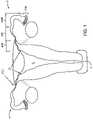
- FIG. 1illustrates the uterine and tubal anatomy for deployment of the contraceptive devices of the present invention.
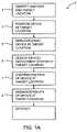
- FIG. 1Aschematically illustrates method steps for an exemplary contraceptive device deployment method.
- FIG. 1Bis a partial cut-away side view of a contraceptive system according to the principles of the present invention.
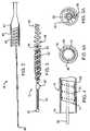
- FIG. 2is a side view of a removable core wire of the contraceptive system of FIG. 1B .
- FIG. 3is a contraceptive device of the contraceptive system of FIG. 1B , in which an outer helical coil is in a large profile configuration.
- FIG. 3Ais an end view of the contraceptive device of FIG. 3 .
- FIG. 3Billustrates a contraceptive device having a tubular band for smoothly disengaging a release pin of a release catheter.
- FIG. 4is a side cross-section of a distal end of a delivery catheter of the contraceptive system of FIG. 1B .
- FIG. 4Ais an axial cross-sectional view of the delivery catheter of FIG. 4 .
- FIG. 5is a side cross-sectional view of an outer sheath of the delivery system of FIG. 1B .
- FIGS. 5A-5Fillustrate sheaths having positioning surfaces for axially positioning the contraceptive device relative to the tubal ostium.
- FIG. 6is a partial cut-away view showing engagement between the outer helical coil of the contraceptive device and the release catheter so as to maintain the wind-down torque on the outer helical coil.
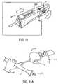
- FIG. 7is a perspective view of the proximal handle of the contraceptive system of FIG. 1B .
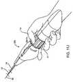
- FIGS. 8A and 8Billustrate a syringe-like handle for use with the contraceptive system of FIG. 1B .
- FIGS. 9A and 9Billustrate a further alternative pistol grip handle for use with the contraceptive system of FIG. 1B .
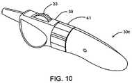
- FIG. 10is a perspective view of a preferred proximal handle of the contraceptive system of FIG. 1B having a thumb wheel, latch, and rotation knob for exposing, expanding, and releasing the contraceptive device at the target location.
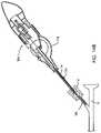
- FIG. 11is a perspective view of an alternative in-line slider handle for use with the contraceptive system of FIG. 1B .
- FIGS. 11A through 11Kschematically illustrate a method for deploying a contraceptive device using the system of FIG. 1B .
- FIGS. 12A and 12Bare side and axial end views schematically illustrating the use of an indentation in the handle to facilitate introducing the guidewire-like distal end of the contraceptive delivery system into a lumen, such as the working lumen of a hysteroscope.
- FIG. 13illustrates an alternative deployment method using an alternative imaging system.
- FIGS. 14A and 14Billustrate a deployment system having a sleeve disposed around the outer sheath, and use of the sleeve to inhibit inadvertent movement of the contraceptive device when the outer sheath is retracted.
- FIG. 15schematically illustrates a side view of alternative distal components for a contraceptive system.
- FIG. 16illustrates an alternative coupling structure at a proximal end of an outer helical coil used in the alternative contraceptive system of FIG. 10 .
- FIG. 17schematically illustrates a contraceptive system having a separate positioning catheter slidably disposed over the sheath, the positioning catheter having a positioning surface to assist in axially positioning of the contraceptive device.
- FIG. 18illustrates a method for using the positioning surface of a sheath or positioning catheter to assist in axially positioning of the contraceptive device.
- FIG. 19schematically illustrates a side view of a contraceptive system, showing axially coupling of the positioning catheter to the contraceptive device.
- FIG. 20schematically illustrates a lateral cross-section of an alternative outer sheath of the delivery system of FIG. 1B .
- FIG. 21schematically illustrates an alternative proximal handle of the contraceptive system.
- the present inventionprovides a contraceptive device, system, and method which can be used to inhibit pregnancy, typically for the long-term inhibition of pregnancy, and often providing permanent contraception or sterilization.
- a contraceptive devicetypically for the long-term inhibition of pregnancy, and often providing permanent contraception or sterilization.
- these contraceptive devicesBy introducing at least a portion of these contraceptive devices into an ostium of a fallopian tube, the risks of unplanned expulsion, pelvic pain, and infectious complications may be significantly reduced.
- the present inventionmay be included within a group of contraceptive techniques generally referred to as fallopian tube occlusion methods, the invention need not be advanced fully into the fallopian tube, and in some embodiments, need not fully block the tubal lumen to effectively disrupt fertilization. As described in co-pending International Patent Application No.
- contraceptionmay optionally be provided by fully occluding the tubal lumen, and/or by sufficiently disrupting the fertilization process without total occlusion.
- including a bioactive material such as coppermay enhance the devices effectiveness.
- a structureis inserted “within a tubal ostium” whenever the structure is advanced from the uterus into (and optionally beyond) the tubal ostium into the uterotubal junction and/or the fallopian tubes.
- Fallopian tubes Fgenerally include three segments between ostium O and the fimbria FIM. Beginning adjacent uterus U, the intramural segment INT of fallopian tubes F are surrounded by the muscular uterine tissues. Beginning at uterotubal junction UTJ, fallopian tubes F extend beyond the uterine tissues and within the peritoneal cavity along an isthmic segment ISC, and then along an ampullary segment AMP.
- the ideal placement for the intrafallopian contraceptive devices of the present inventionis spanning the intramural INT to isthmic ISC portion of the fallopian tube.
- a radially expandable attachment mechanismsuch as an outer coil is included on the intrafallopian contraceptive device
- that expandable or anchoring structurewill preferably span the uterotubal junction UTJ.
- the uterotubal junction UTJmay be defined as the plane where the fallopian tube meets the peritoneal cavity.
- the narrowest portion of the fallopian tubeneed not necessarily be disposed in the isthmic segment ISC, particularly once the contraceptive fallopian device (often having a radially expandable anchoring structure) is deployed therein. In fact, work in connection with the present invention has shown that the effectively narrowest portion of the tube may be at or adjacent the uterotubal junction UTJ.
- FIG. 1Aan overview of an exemplary method 2 for deploying and using the contraceptive devices of the present invention is helpful to understand the selection of structures used in those devices. It should be understood that not all steps need be performed in every deployment. Nonetheless, reviewing the exemplary deployment method 2 will help to understand the structures described hereinbelow.
- Identification of the anatomy and target location 3allows the operator to determine the preferred placement of the contraceptive device within the ostium, and also to determine if any special circumstances are present for a particular device placement procedure.
- Anatomy and target location identificationcan be facilitated using a variety of known visualization modes, including hysteroscopy, sonography (ultrasound), fluoroscopy, and the like.
- an exemplary contraceptive devicemay be adapted to delivery using more than one imaging modality.
- the exemplary contraceptive devicewill also preferably be able to accommodate a wide variety of anatomies. Two factors contribute to the importance of this variability: First, a wide variation may be observed between tubal anatomies of differing patients. Secondly, it can be quite difficult to determine and identify the specific tubal anatomy of a particular patient. As a result, the preferred contraceptive device may incorporate safeguards allowing sufficiently accurate placement (with tolerance for normal operator error), as well as for the variance in the length and diameter of the various segments of the fallopian tube.
- Exemplary deployment method 2 in FIG. 1Awill also include positioning of the device at the target location 4 .
- a wide variety of techniquesmight be used to assist a healthcare professional in positioning the device in the correct location, including visualization techniques, providing high-contrast markers (such as radiopaque markers, echogenic markers, or the like), providing tactile indication of the placement position by including physical stops or “bumpers” (which may be adapted to engage reference tissues in such a tactile way as to send a signal to the healthcare professional), or the like.
- Device positioningcan be significantly facilitated by providing an appropriate device and/or deployment system design having the proper flexibility, navigation characteristics, friction reduction surfaces, small delivery profile, coatings, and the like.
- device positioning 4will preferably compensate for anatomical variations, operator error, and difficulties in visualization so as to help promote accurate placement.
- the deviceis deployed and/or expanded at the target location in the step indicated by reference numeral 5 .
- the device and/or deployment systemmay allow visualization and/or confirmation of device expansion while expansion takes place.
- the contraceptive devicewill be detached from its deployment system at the target location in step 6 .
- it is helpful to provide visualization and/or confirmation of detachmentwhich may be provided visually, via ultrasound, fluoroscopy, or the like. It should be understood that a wide variety of detachment mechanisms might be used to decouple the device from the deployment system.
- the exemplary methodit should be possible to confirm the position of the device at the target location 7 .
- Confirmationmay be provided, once again, by visualizing at least a portion of the device after detachment, often using the same visualization modality used during placement.
- thismay be provided by including radiopaque markers for fluoroscopic placement confirmation, sonographic markers for ultrasound placement confirmation, or the like.
- specific marker locationsmay be provided along the contraceptive device 2 , for example, to indicate the specific locations of proximal and/or distal ends of the device.
- Exemplary method 2further includes a step 9 for anchoring and stability of the device at the target location. Aspects of this step include accommodating visualization of the device so as to monitor it's stability.
- Anchoring of the device at the target locationmay include anchoring on an acute basis (such as using an expanded helical coil that can adjust and adapt to variations in the tubal lumen, an expanded stent-like structure, expanded braid, or the like) and long-term (such as may be provided by including a fiber mesh or lattice which incites a tissue reaction such as ingrowth, thereby providing fibrous tissues which affix the device in place within the fallopian tube).
- stabilitywill preferably be provided for both a short-term and a long-term, typically by designing a device with the proper resiliency and shape to accommodate physiological movement without shifting.
- the devicewill preferably be wear-profile balanced to provide sufficient anchoring without inducing pain or losing its stability due to erosion for the life of the patient.
- the final step indicated on the exemplary method 2 of FIG. 1Ais efficacy.
- Thismay be provided by incorporating a lumen/space filling design that sufficiently alters the function and architecture of the fallopian tube so as to inhibit conception.
- Thismay include the use of polyester fibers to incite the desired tissue reaction.
- the devices of the present inventionmay be adapted to incite a reaction tissue response in the fallopian tube through the presence polyester fibers, or the like.
- this reactioncan be classified as a highly localized, benign tissue reaction.
- the reactionresults in the incorporation of the contraceptive device into the tubal lumen tissues, so that the device is firmly embedded into the surrounding tissue structure.
- This reactioncan typically be characterized by the proliferation of smooth muscle cells and associated fibrosis.
- the tubal lumenwill generally exhibit an absence of the normal tubal architecture which is generally necessary for conception.
- the tubal lumenmay also be obstructed, occluded, and/or functionally occluded by the presence of the device and associated fibrosis sufficiently to inhibit conception.
- the reactionis a benign one, and there appears to be no change in anatomy or structure of the outer tubal wall beyond approximately 5 to 10 mm radially outwardly from the outer coil of the device. Similarly, normal tubal architecture will often be visible about 5 mm axially beyond the device (typically distal of the device, as the device often extends into the uterus), again indicating a very localized reaction.
- an exemplary contraceptive system 10generally includes a contraceptive device 12 , a sheath 14 partially surrounding the contraceptive device, a release catheter 16 , and a core shaft 18 .
- Contraceptive device 12generally has a proximal portion 20 adjacent a proximal end 22 (disposed within sheath 14 ), and a distal portion 24 adjacent a distal end 26 (which are exposed beyond the distal end of sheath 14 ).
- Distal portion 24generally functions as a distal guidewire while system 10 is advanced within the tubal ostium.
- Proximal portion 20includes a radially expandable structure which can be expanded after sheath 14 is withdrawn so as to affix the contraceptive device in the deployed position.
- Sheath 14is generally a tubular structure having a distal end 28 and extending proximally to a proximal handle 30 .
- Sheath 14will generally have a length in a range from about 25 to about 50 cm, and will typically have an outer diameter in a range from about 0.020 to about 0.060 inches, the exemplary sheath having a length of about 39.5 cm and an outer diameter of about 0.04 inches.
- the inner diameter of sheath 14may be in a range from about 0.02 inches to about 0.05 inches, with the exemplary sheath having an inner diameter of about 0.33 inches.
- Release catheter 16generally comprises a tube having a distal end 34 which releasably engages contraceptive device 12 , and a proximal end coupled to housing 30 via actuator 33 .
- core shaft 18comprises a resilient tapering structure extending from within distal portion 24 of contraceptive device 12 proximally to handle 30 .
- Core shaft 18threadably engages contraceptive device 12 proximally of distal end 28 of sheath 14 .
- core shaft 18 and release catheter 16transmit a wind-down torque onto an expandable structure of the contraceptive device so as to maintain the expandable structure in the small profile configuration.
- releasing core shaft 18 relative to release catheter 16allows the expandable structure to be activated independently of movement of the surrounding sheath.
- Handle 30includes a housing 31 having a size and shape suitable for gripping with a single hand.
- a thumb wheel actuator 33performs two actuation functions: first, rotation of the thumb wheel relative to housing 31 draws sheath 14 proximally by engagement between pinion 35 (attached to the thumb wheel) and rack 37 (attached to sheath 14 ). During this initial movement, release catheter 16 is restrained relative to housing 31 by latch 39 . Once the proximal end of rack 37 engages a cooperating surface attached to release catheter 16 , latch 39 can be actuated to allow release catheter 16 to move relative to the housing as the thumb wheel 33 is again turned in the direction shown.
- spring 51may be compressed by rotation of the thumb wheel prior to actuation of latch 39 , so that actuation of the latch slides the release catheter so as to disengage the release catheter from contraceptive device 12 .
- a proximal end of core shaft 18is affixed to the housing so that the core shaft is rotated by rotating the entire housing.
- Components of housing 31 and actuators 33 , 39will generally comprise polymers, metals, or the like.
- the actuator mechanismmay include molded and/or machined parts, and may be permanently attached to sheath 14 , release catheter 16 , core shaft 18 , and the like so that the remaining components of the delivery system 10 are disposed of once contraceptive device 12 has been deployed.
- housing 31has an overall length in a range from about 2 to about 8 inches, ideally having a length of about 7.5 inches.
- the exemplary embodiment of rack 37has a length of about 5.5 cm and a total travel stroke of about 4.0 cm.
- Release catheter 16has a stroke of about 1 cm, and movement of the release catheter relative to core shaft 18 is inhibited prior to actuation of latch 39 .
- Unthreading of core shaft 18 from device 12will typically be complete in about 10 rotations or less, ideally being unthreaded with from about one quarter to about 2 full rotations of the handle (or other rotational mechanism).
- exemplary contraceptive device 12makes use of a radially expandable helical coil to help restrain the structure during tissue ingrowth
- a wide variety of mechanical and other restraint mechanismsmight be included.
- alternative mechanical anchorsmight be attached to the device, such as resilient coils biased to form bends, loops, and/or other secondary shapes having enhanced cross-sections, slotted tubes, Malecot-type structures, radially expandable braids, stent-like devices, and the like.
- the mechanical structuresmay be resilient, plastically deformable, or the like, and suitable structures are described in more detail in, for example, PCT Publication No. WO 99/15116.
- Still further device-restraint techniquesmight be employed, including thermal, chemical, adhesive, and the like. These techniques can be used to avoid expulsion by increasing friction between the device and the surrounding tissues, by imposing limited tissue damage to promote scar tissue formation, and/or by promoting tissue ingrowth into the device.
- Thermal techniquesmay include, for example, transmission of electrical or laser energy along contraceptive system 10 . Resistive heating of contraceptive device 10 might be effected by applying an electrical potential across the device with conductors extending along sheath 14 and release catheter 16 , laser energy along an optical wave guide attached to core wire 18 , or the like.
- Tissue reaction to the retained contraceptive device 12can help to provide long term contraception and/or sterilization.
- device 12will often include a tissue reaction material, the material often comprising fibers.
- the fibersmay comprise a polyester, such as Dacron® polyesters, silk, nylon, or the like.
- the fibersmay be in the form of a weave, a knit, a braid, a felt, or the like, or may comprise stands attached to the device body.
- core shaft 18tapers to a gradually increasing diameter proximally of distal end 40 so as to provide increasing support of distal portion 24 , proximal portion 20 , and the catheter structures proximal of contraceptive device 12 .
- This increasing supportenhances the pushability of the contraceptive system while accessing the target deployment site.
- Threads 42threadingly engage a coil of the contraceptive device, and are generally formed by affixing a coil with separated windings to a central core wire at a bond 44 .
- a tube 43may also be affixed at bond 44 to prevent binding and/or jumping of the cooperating threads, the tube ideally comprising stainless steel, platinum, or the like.
- core shaft 18comprises a high strength metallic structure.
- Contraceptive device 12includes a primary coil 50 which extends from a distal ball tip 52 to proximal threads 54 , which may conveniently be formed by separating the proximal windings of the primary coil.
- the expandable structurehere in the form of a helical outer coil 56 , has a proximal end bent to form a wind-down attachment 58 , and has a distal end affixed to coil 50 at coil bond 60 .
- Fiber 62extends between the inner and outer coils, and is also disposed within primary coil 50 so as to promote tissue ingrowth throughout the cross-section of contraceptive device 12 .
- the arrangement of coil attachment 58 and position of fiber 62can be seen in the axial view of FIG. 3A .
- a contraceptive device having a distal portion 24 which can act as a guidewireno open lumen need be provided through the center of the contraceptive device (for example, for a separate guidewire), and multiple access/deployment steps (for example, accessing the target location with a guidewire, advancing a catheter over the guidewire, removing the guidewire from the positioned catheter, and then advancing the contraceptive device) can be avoided.
- the exemplary systemuses threads to couple the core wire (or other deployment shaft) to the contraceptive device, a variety of alternative detachable connections might be used, including cooperating keys/slots, connectors, or the like.
- coil 50is formed of a high strength resilient material, ideally comprising stainless steel wire having a diameter of about 0.005 inches, and wound to form a coil having an outer diameter of about 0.022 inches.
- Ball tip 52preferably has a cross-section which is larger than the cross-section of coil 50 , the ball tip generally having a diameter in a range from about 0.020 inches to about 0.050 inches, the exemplary ball tip having a diameter of 0.027 inches.
- Helical coil 56comprises a highly elastic high strength metal which is biased to expand from the low profile configuration illustrated in FIG. 1 to the larger profile configuration illustrated in FIG. 3 when released within the target site.
- outer coil 56comprises a ribbon of a superelastic shape memory alloy, and has a thickness of about 0.001 inches and a width of about 0.015 inches, with the ribbon being biased to form a helical coil having an outer diameter of about 0.080 inches and a length of about 3.5 cm when not otherwise restrained.
- Outer coil 56is preferably fixed to primary coil 50 by a bond 60 of solder. Bond 60 will preferably be separated from ball tip 52 by a distance in a range from about 0.3 cm to about 1.0 cm.
- bond 60may be aligned with the distal end 28 of sheath 14 so as to help present an atraumatic increase in diameter between distal portion 24 of contraceptive device 12 and the sheathed proximal portion 20 prior to deployment.
- Fiber 62may comprise a polyester, or the like.
- the fibermay be loosely woven or matted strands, with at least one end of the fibers affixed to primary coil 50 or outer coil 56 .
- the expandable structurewill at least help hold contraceptive device 12 in place until tissue ingrowth occurs sufficiently so as to permanently retain the contraceptive device.
- the expandable structurewill often benefit from a relatively high friction outer surface. Such an outer surface might make it difficult to advance the contraceptive device into position if the device is advanced without sheath 14 .
- outer coil 56is preferably maintained in a small profile configuration within sheath 14 by applying a wind-down torque between core wire 18 and release catheter 16 .
- the core wirecan transfer the wind-down torque to outer coil 16 through cooperating threads 42 , 54 , with the direction of the wind-down torque preferably being arranged so that the wind-down torque discourages decoupling of the threads.
- rotation of core wire 18 relative to contraceptive device 12 in a direction opposed to the wind-down torqueis used to detach core wire 18 from contraceptive device 12 .
- An alternative contraceptive device 12 aincludes a small tube or band 59 soldered within a small diameter proximal section of the outer coil 56 .
- Band 59can have a relatively large interface area with coil 56 to facilitate bonding. Use of the band helps avoid stress concentrations, and also presents a smooth inner lumen which may inhibit binding of the release catheter.
- Band 59may comprise stainless or platinum, ideally having an inner diameter of about 0.023 inches and an outer diameter, with a thickness of the surrounding outer coil and solder bond, of about 0.030 inches.
- a similar band 59 ′may be disposed within threads 54 of coil 50 to provide a radiopaque marker, and to inhibit thread jump.
- Band 59 ′may be similar in structure to band 59 , but shorter in length. Still further alternative attachment mechanisms are possible. For example, a mass or knob may be formed at the proximal end of outer coil 56 from a simple ball of solder, coil material, bend, or the like. This mass may be slidably receivable within slot of the delivery catheter.
- release catheter 16The distal structure of release catheter 16 is shown in FIGS. 4 and 4A .
- the wind-down torqueis releasably transferred between outer coil 56 and release catheter 16 by cooperation between bend 58 and pin 66 at the distal end 34 of the release catheter 16 .
- Release catheter 16generally includes a tubular body 68 formed of rigid polymers such as polyimide. Pin 66 is disposed within a lumen of tubular body 68 , and is supported within the tubular body by a helical support coil 70 and adhesive 72 . Interestingly, the tubular body dimensions may be driven by the wind-down torque transferred proximally by release catheter 16 .
- Distal end 28 (see FIG. 5A ) of sheath 14will preferably be rounded, with the distal end ideally cooperating with coil bond 60 of contraceptive device 12 so as to avoid friction and facilitate distal navigation of delivery system 16 through the uterotubal junction and into the fallopian tube.
- the rounded distal end 28may optionally be rounded along both the inner and outer diameter of sheath 14 , or may primarily be rounded along the outer diameter so as to taper inwardly distally.
- Sheath 14will preferably have a multi-layer structure, with the layers comprising (beginning at the outside) a hydrophilic coating 76 to reduce friction during tracking and navigation.
- a hydrophilic coating 76to reduce friction during tracking and navigation.
- Such hydrophilic coatingsbecome quite slippery when exposed to fluid.
- Below hydrophilic coating 76is a structural layer of a polymer 78 such as TecoflexTM along the proximal portion of sheath 14 , and a reinforcing braid 80 of a metal, ideally of stainless steel, is disposed within a layer of polyimide below polymer layer 78 .
- metal braid 82is disposed within polymer layer 78 of TecoflexTM, or the like, and the polyimide layer is absent so as to provide enhanced flexibility.
- the inner lumen of sheath 14is defined by a low friction polymer coating 84 , the low friction polymer ideally comprising a PTFE such as Teflon®.
- exemplary sheaths 14may be commercially available from a variety of vendors. Suitable structures may be described in more detail in published PCT patent application WO 98/57589, the full disclosure of which is incorporated herein by reference.
- alternative sheaths 14 A, B, and Cinclude bumpers 57 , 57 ′, and 57 ′′, respectively.
- Bumper 57has an outer surface extending radially from the outer surface of the underlying sheath.
- bumper 57may optionally provide a tactile indication that the sheath 14 A is advancing distally beyond the target deployment position, it does not necessarily prevent the sheath from advancing so that the bumper can enter into the tubal ostium.
- Bumper 57may also provide a visible marker that hinders pushing of the sheath so that the bumper moves past the ostium.
- bumper 57may comprise a colored adhesive, or may comprise a clear adhesive with a colored band of material disposed underneath.
- Alternative bumpers 57 ′ and 57 ′′may comprise polymer or metallic structures, ideally comprising a polyethylene or a super-elastic, shape-memory alloy. These radially expandable bumper structures can be collapsed for delivery through a working lumen of a hysteroscope, and can then expand to impede advancement of the sheath by engaging the uterine tissue adjacent to the tubal ostium.
- FIG. 6shows how the wind-down torque imposed on the outer coil by the core shaft 18 and release catheter 16 help maintain the outer coil in a small profile configuration within sheath 14 , allowing the sheath to be withdrawn easily.
- the wind-down torquecan be released by sliding release catheter 16 so that pin 66 slides free of bend 58 .
- the release cathetermay first be allowed to rotate relative to the core shaft to reduce the engagement forces between bend 58 and pin 66 .
- thumb wheel 33 and latch 39are conveniently located for actuation by a thumb of a surgeon, nurse, or other healthcare professional while the healthcare professional grips handle 30 with the remaining fingers of the hand. This allows the healthcare professional to perform several of the deployment steps with a single hand.
- movement of overall housing 31is used to advance contraceptive device 12 distally into the tubal ostium, and to navigate the contraceptive delivery system within the uterotubal junction and fallopian tube.
- thumb wheel 33withdraws sheath 14 from over the contraceptive device, while housing 31 continues to rotationally and axially couple the proximal ends of the release catheter 16 and core shaft 18 , thereby maintaining the wind-down torque on the contraceptive device so as to restrain the contraceptive device in its small diameter configuration.
- latch 39can be depressed and thumb wheel 33 can again be turned proximally to disengage pin 66 of release catheter 16 from the wound-down outer coil of the contraceptive device, thereby radially expanding the contraceptive device.
- thumb wheel 33can again be turned proximally to disengage pin 66 of release catheter 16 from the wound-down outer coil of the contraceptive device, thereby radially expanding the contraceptive device.
- handle 30is rotated as illustrated to threadingly disengage core shaft 18 from the contraceptive device 12 .
- handle 30allows the healthcare professional to position the contraceptive device, expose the contraceptive device, actuate the contraceptive device so as to affix the device to the surrounding tissue, and decouple the contraceptive device from the remaining components of the delivery system with a single hand.
- an axial motion “T” handle 30 auses a syringe-type axial pull motion to pull sheath 30 back with the fingers of a hand towards a palm of the hand (which is generally held at a fixed position). This effects axial motion of sheath 14 to withdraw the sheath from over the contraceptive device, followed by axial motion of release catheter 16 to allow the contraceptive device to expand.
- a knob 41may be affixed to the proximal end of core shaft 18 , so that rotation of knob 41 threadingly disengages the core wire from the expanded contraceptive device.
- Knob 41may include a releasable latch coupling the knob to the housing to prevent rotation of the core shaft and maintain the wind-down torque until release is desired.
- axial motion handle 30 aallows for multiple hand sizes and various hand positions, and presents a form which is familiar to doctors.
- FIGS. 9A and Billustrate a still further alternative pistol grip handle 30 b for effecting one-handed deployment of the contraceptive device.
- a trigger actuator 43moves sheath 14 and release catheter 16 via a bead chain 45 and a bead chain drive wheel and gear arrangement.
- a latch button(not shown) may be depressed and knob 41 rotated by a thumb of the hand to decouple the contraceptive device from core shaft 18 .
- a preferred one-handed release handle 30 cincludes a thumb wheel 33 which, when turned relative to the surrounding housing, initially causes movement of sheath 14 relative to core shaft 18 as will be described in detail herein below.
- depressing safety latch 39allows the thumb wheel to again be rotated so as to move release catheter 16 relative to the core shaft to allow the contraceptive device to expand.
- These movements of thumb wheel 33can easily be performed while maintaining the housing of preferred handle 30 c at a fixed location, thereby avoiding movement to the contraceptive device.
- knob 41may be rotated, again while holding the remaining handle at a fixed location.
- the internal mechanism providing these movementsis illustrated in FIGS. 11D , 11 E, 11 F, and 11 H.
- one-handed release handlesmay be provided, including an in-line slider handle 30 d having a thumb slide 47 for sequential movement of the sheath 14 and then release catheter 16 relative to core shaft 18 , as shown in FIG. 10 .
- a knob 41may be allowed to rotate relative to the housing by depressing a latch 39 , or the entire housing may be rotated to detach the engagement threads, as described above.
- a healthcare workerwill manipulate contraceptive delivery system 10 with a first hand H 1 while supporting an imaging and/or access device such as a fluoroscopy catheter, sonography catheter, or hysteroscope S with a second hand H 2 .
- an imaging and/or access devicesuch as a fluoroscopy catheter, sonography catheter, or hysteroscope S with a second hand H 2 .
- Thisallows the healthcare professional to personally control the orientation of distal advancement of the contraceptive system and its movement and deployment while viewing the procedure through the scope S (shown here schematically by eye E).
- scope Sis illustrated here as a simple optical device, it should be understood that a variety of scope structures are encompassed by the system and method of the present invention, including rigid optical scopes, scopes having a coherent fiber optic bundles, scopes which include charge-couple devices (CCD's) for displaying an image of the procedure in a monitor, and the like).
- CCD'scharge-couple devices
- Exemplary hysteroscopes for use with the present inventionare commercially available from Richard Wolf of Chicago, Ill. under model name 5 MM O VAL S COPE .
- system 10is introduced transcervically through uterus U, generally under optical direction.
- the physiciandirects the distal end of the system toward ostium O of fallopian tube F.
- Uterus Umay be irrigated and/or distended using scope S and/or a separate irrigation or gas insufflation system.
- system 10is advanced distally through the working lumen of the scope and into the ostium using distal portion 24 of the contraceptive device as a guidewire, while the remainder of the contraceptive device remains covered by sheath 14 .
- the outer hydrophilic coating of sheath 14minimizes friction while advancing system 10 , and the sheath also provides structural column strength to the system.
- the distal ball tip of distal portion 24aids tracking and navigation through fallopian tube F, while the primary coil structure flexes laterally to track the tortuous bends often found within the fallopian tube.
- core wire 18extends into distal portion 24 to enhance column strength of the distal portion beyond sheath 14 , but does not extend to the ball tip.
- the stiffness of distal portion 24increases proximally, further enhancing the distal portion's ability to track the lumen.
- sheath 14includes a visual marker 98 which can be seen from the scope of hysteroscope S.
- Marker 98will preferably be positioned partially within ostium O and partially within uterus U, thereby indicating that contraceptive device 12 is disposed at the target position, as the sheath, core shaft, and contraceptive device are releasably locked together during advancement and positioning an opening (as the sheath, core shaft, and contraceptive device are releasably locked together during advancement and positioning).
- marker 98may comprise a bumper, a structure which extends radially from the sheath to provide a tactile positioning indication.
- FIG. 11CPreferred positioning of contraceptive device 12 is illustrated in FIG. 11C .
- device 12extends across the uterotubal junction UTJ, with the device ideally extending both proximally and distally of the uterotubal junction.
- the intermural section INTtypically has a length in a range from about 1 to about 2 cm, and outer coil 56 will preferably extend proximally beyond ostium O into uterus U by a distance in a range from about 0.2 to about 1.2 cm. Outer coil 56 will preferably extend distally of the intermural section INT and/or uterotubal junction UTJ by a distance of at least about 0.6 cm.
- the narrowest portion of the fallopian tube(particularly after deployment of device 12 ) will often be found adjacent the uterotubal junction. Extending the expandable structure both distally and proximally of this narrowing can provide anchoring against proximal and distal movement of the device, thereby avoiding movement of contraceptive device 12 from the target position while tissue ingrowth takes place.
- positioning accuracywith a range of about 1 cm may be provided by limiting marker 98 to a 1 cm length. This provides a sufficient positional tolerance for ease of use while helping to ensure reliable, well-anchored deployments.
- positioned contraceptive device 12is deployed by first withdrawing sheath 14 from over the expandable structure.
- thumb wheel 33is rotated proximally by thumb TH to draw sheath 14 proximally from over the contraceptive device.
- Handle 30is held in a fixed position, while the thumb wheel is rotated, so that core shaft 18 maintains contraceptive device 12 at the target location within the tubal ostium.
- rack 37engages the corresponding proximal structure of release catheter 16
- further movement of sheath 14 and thumb wheel 33will be impeded until latch 39 is depressed, as can be understood with reference to FIG. 11B .
- device 12has been positioned at the target location, and sheath 14 has been withdrawn proximally allowing the proximal portion of the contraceptive device to be viewed from Scope so as to verify initial positioning.
- latch 39is depressed so as to allow the proximal structure of release catheter 16 to be moved axially by rack 37 .
- thumb wheel 33can again be rotated so as to draw both sheath 14 and release catheter 16 proximally relative to core shaft 18 .
- this rotationally decouples the outer coil of the contraceptive device from the release catheter 16allowing the release catheter to expand.
- spring 51hinders rotation of thumb wheel 33 until latch 39 is depressed.
- spring 51may store sufficient energy to move release catheter 16 relative to core shaft 18 when latch 39 is actuated, or spring 51 may be entirely absent so that latch 39 allows the thumb wheel to expand the expansible structure by moving both sheath 14 and release catheter 16 relative to the core shaft 18 .
- handle 30may be rotated to disengage the contraceptive device 12 from the remaining components of delivery system 10 .
- sliding proximal structure 16 a attached to proximal end of release catheter 16proximally allows a proximal structure 18 a of core shaft 18 to rotate. More specifically, splines on the proximal structure of the release catheter are moved axially beyond cooperating splines on the proximal structure of the core shaft.
- the core shaft proximal structure 18 ais rotationally coupled to knob 41 , so that the cooperating splines prevent rotation of the knob prior to the deployment's stroke of the release catheter, but thereafter allow the knob to be rotated so as to facilitate decoupling of core shaft 18 from the contraceptive device.
- Scope Smay be remain within uterus U and another delivery system may be inserted into the scope for deployment of a contraceptive device in the ostium of the opposed fallopian tube. After deployment of both contraceptive device in the two fallopian tubes, and after the scope is used to visually verify both deployments have been successful, the scope is withdrawn transcervically from the uterus, as illustrated in FIG. 11K .
- a slotted handle 30 dpreferably includes a slot 100 which laterally receives sheath 14 when the distal portion of delivery system 10 is bent as shown.
- slot 100fittingly receives sheath 14 adjacent the distal end of the delivery system.
- Detents 102extend from the housing into slot 100 and restrain sheath 14 within slot 100 against the resilient straightening forces from the sheath, from release catheter 16 , and from core shaft 18 .
- the elongate components of delivery system 10which extend distally from handle 30 d to the distal end of distal portion 24 present an elongate guiding structure with a lateral flexibility which increases distally toward the distal end.
- the guiding structurecan be easily inserted into a working lumen W of hysteroscope S using handle 30 d . This avoids having a long flexible guidewire-like structure extending in cantilever a considerable distance from the handle, or having the dead weight of the handle flopping uncontrollably while the delivery system is grasped adjacent the distal end of sheath 14 to insert distal portion 24 into the working lumen.
- Such a structurewill have a wide variety of applications for guidewires and guidewire-like structures having proximal handles for facilitating insertion of their distal ends into lumens of vascular access catheters, insertion sheaths, monorail catheter lumens, and the like.
- a variety of alternative deployment methodsmight be used to deploy the contraceptive system 10 .
- deploymentmight be directed sonographically, fluorscopically, under magnetic resonance imaging, and possibly even solely from tactile information.
- a balloon 104 of cervical catheter 102is inflated via inflation port 106 .
- Thisallows the uterus U to be distended by introduction of distention media through a uterine catheter 108 inserted through the working lumen of cervical catheter 102 .
- anatomy and target location identification, device positioning, deployment, detachment, and position confirmation(as outlined in method 2 with reference to FIG.
- the delivery systems of the present inventionwill often hold the contraceptive device in a fixed position while the contraceptive device is uncovered, expanded, and/or released.
- friction between the outer sheath and the surrounding hysteroscopeor other introducing structure, surrounding tissue, or the like
- an outer sleevemay be slidably disposed around outer sheath 14 .
- the sleeveprovides a sliding interface between the sheath and surrounding structures.
- a sleeve 112is slidably disposed around at lease a proximal portion of sheath 14 .
- Sleeve 112is axially restrained relative to core shaft 18 by axially connecting the proximal end of the sleeve to housing 110 of handle 30 c ′, optionally using a rotatable connector 114 (to allow the sleeve to rotate relative to the housing).
- Sleeve 112will often have a distal end disposed proximally of contraceptive device 12 .
- sleeve 112will often advance into a sealing introducer structure such as a nipple value V of hysteroscope S.
- Sleeve 112may also extend at least through the bend where a working lumen WL of the hysteroscope joins the main shaft of the scope.
- Sleeve 112allows independent movement of sheath 14 despite frictional engagement between the sleeve and nipple valve V, and between the sleeve and working lumen WL.
- Rotatable connector 114allows free rotation of handle 30 c ′ (and core shaft 18 ) during disengagement of the core shaft from the contraceptive device.
- an alternative contraceptive system 150includes a contraceptive device 152 having many of the components described above, but having an alternative wind-down outer coil connector 154 disposed at a proximal end of outer coil 56 .
- wind-down connector 160 of release catheter 158comprises an opening which receives a protrusion 162 extending radially from a tubular band of connector 154 .
- positioning surface 57may optionally be affixed to sheath 14 to help axially position contraceptive device 152 across intermural region INT, as described above. Engagement between radially protruding positioning surface 57 and the uterine tissue surrounding ostium O facilitates initial axial positioning by taking advantage of the axial coupling of sheath 14 to the contraceptive device. However, sheath 14 will often be withdrawn proximally into scope S early-on during deployment, and it is often desirable to maintain the axial position of the contraceptive device at least until proximal coil 56 begins to expand radially.
- axial positioning surface 57(which may optionally comprise any of the alternative positioning surface configurations described hereinabove, or still further alternative structures) at a distal end of a separate positioning catheter 184 slidably disposed over sheath 14 , the axial positioning provided by the positioning surface may be maintained during and/or after withdrawal of sheath 14 .
- a proximal portion 186 of positioning catheter 184may be axially coupled to a distal portion of handle 30 .
- This arrangementis fairly easy to manufacture, and effectively axially couples contraceptive device 152 to positioning surface 57 via handle 30 .
- positioning catheter 184may be axially coupled to the release catheter within sheath 14 , or to any of the other axially elongate delivery system components extending distally from the handle.
- positioning surface 57extends distally of the proximal end of outer coil 56 , it is possible that the proximal portion of the outer coil will expand partially in the positioning catheter, particularly where the positioning catheter is affixed axially to handle 30 and handle 30 is affixed axially to the core wire.
- Axial coupling of the positioning catheter to the release cathetermay allow at least partial withdrawal of the positioning catheter prior to expansion of the outer coil.
- a distal portion of positioning catheter 184 , positioning surface 57 , and/or a proximal portion of outer coil 56may be adapted so as to facilitate proximal withdrawal of the positioning catheter after the outer coil has expanded, such as by limiting a diameter of a proximal portion of the outer coil, providing a low friction surface along an inner lumen of the release catheter and/or along the outer surface of the proximal portion of the outer coil, or the like.
- the relatively high friction outer surface of the distal portion of outer coil 56 within the ostium of the fallopian tubewill help inhibit axial movement of the contraceptive device after sheath 14 is withdrawn proximally.
- sheath 214may be used in place of outer sheath 14 in the system of FIG. 1B .
- Sheath 214has a proximal portion 216 with a relatively stiff, thicker-walled tubular structure, such as a PeBax® polymer tube having an outer diameter of about 0.062′′, and an inner diameter of about 0.042′′.
- a distal portion of sheath 14includes an inner tube 218 of a low friction polymer and an outer tube 220 of a polymer, (such as carbothaneTM 73 A) with at least one ribbon coil 222 therebetween.
- Inner tube 218may comprise a PTFE (such as a Teflon® material) with an inner diameter of about 0.034′′ and a wall thickness of about 0.001′′ with the outer diameter etched, and a length of about 5.0 cm, while there are preferably two counterwound ribbon coils 222 of a superelastic or shape memory alloy, such as nickel titanium (optionally with chromium) of about 0.007′′ by about 0.010′′ with a pitch of about 0.015′′ and a length of about 4.0 cm.
- Inner tube 218might alternatively comprise ETFE, gamma stable PTFE, FEP, or the like, while ribbon coils 222 may comprise a stainless steel or other medical grade materials.
- An inner diameter of the distal portionmay be about 0.034′′, with the distal outer diameter of sheath 214 being about 0.041′′.
- An intermediate outer tube 224may comprise a polyurethane having a durometer of about 55.
- a length of outer tube 220may be about 1.0 cm, a length of intermediate tube 224 may be about 5 mm, and a length of proximal portion 216 may be about 40 cm.
- a still further alternative proximal handle 230includes many of the axial movement components of handle 30 c , as described above. Rather than providing a rotatable knob 41 , detachment of the contraceptive device from the core wire 18 of the delivery system may be effected by rotation of handle 230 about the axis of the corewire. Still further options are possible, including the detachment of a distal portion of the corewire from the proximal portion, so that the distal portion remains within the contraceptive device after deployment.
Landscapes
- Health & Medical Sciences (AREA)
- Biomedical Technology (AREA)
- Engineering & Computer Science (AREA)
- Life Sciences & Earth Sciences (AREA)
- Heart & Thoracic Surgery (AREA)
- Vascular Medicine (AREA)
- Animal Behavior & Ethology (AREA)
- General Health & Medical Sciences (AREA)
- Public Health (AREA)
- Veterinary Medicine (AREA)
- Reproductive Health (AREA)
- Cardiology (AREA)
- Oral & Maxillofacial Surgery (AREA)
- Transplantation (AREA)
- Orthopedics, Nursing, And Contraception (AREA)
Abstract
Description
Claims (7)
Priority Applications (7)
| Application Number | Priority Date | Filing Date | Title |
|---|---|---|---|
| US11/154,144US7591268B2 (en) | 1999-08-23 | 2005-06-15 | Deployment actuation system for intrafallopian contraception |
| US12/506,953US7934504B2 (en) | 1999-08-23 | 2009-07-21 | Deployment actuation system for intrafallopian contraception |
| US13/073,910US8079364B2 (en) | 1999-08-23 | 2011-03-28 | Deployment actuation system for intrafallopian contraception |
| US13/294,749US8381733B2 (en) | 1999-08-23 | 2011-11-11 | Deployment actuation system |
| US13/369,042US8584679B2 (en) | 1999-08-23 | 2012-02-08 | Deployment actuation system |
| US13/468,962US8695604B2 (en) | 1999-08-23 | 2012-05-10 | Deployment actuation system |
| US14/245,941US9597224B2 (en) | 1999-08-23 | 2014-04-04 | Deployment actuation system |
Applications Claiming Priority (4)
| Application Number | Priority Date | Filing Date | Title |
|---|---|---|---|
| US15023899P | 1999-08-23 | 1999-08-23 | |
| US09/644,287US6709667B1 (en) | 1999-08-23 | 2000-08-22 | Deployment actuation system for intrafallopian contraception |
| US10/785,553US7506650B2 (en) | 1999-08-23 | 2004-02-23 | Deployment actuation system for intrafallopian contraception |
| US11/154,144US7591268B2 (en) | 1999-08-23 | 2005-06-15 | Deployment actuation system for intrafallopian contraception |
Related Parent Applications (2)
| Application Number | Title | Priority Date | Filing Date |
|---|---|---|---|
| US09/644,287ContinuationUS6709667B1 (en) | 1999-08-23 | 2000-08-22 | Deployment actuation system for intrafallopian contraception |
| US10/785,553ContinuationUS7506650B2 (en) | 1999-08-23 | 2004-02-23 | Deployment actuation system for intrafallopian contraception |
Related Child Applications (2)
| Application Number | Title | Priority Date | Filing Date |
|---|---|---|---|
| US12/506,953ContinuationUS7934504B2 (en) | 1999-08-23 | 2009-07-21 | Deployment actuation system for intrafallopian contraception |
| US12/506,983ContinuationUS8422708B2 (en) | 2008-07-24 | 2009-07-21 | Adaptive long-term prediction filter for adaptive whitening |
Publications (2)
| Publication Number | Publication Date |
|---|---|
| US20050232961A1 US20050232961A1 (en) | 2005-10-20 |
| US7591268B2true US7591268B2 (en) | 2009-09-22 |
Family
ID=31980874
Family Applications (9)
| Application Number | Title | Priority Date | Filing Date |
|---|---|---|---|
| US09/644,287Expired - LifetimeUS6709667B1 (en) | 1999-08-23 | 2000-08-22 | Deployment actuation system for intrafallopian contraception |
| US10/785,553Expired - Fee RelatedUS7506650B2 (en) | 1999-08-23 | 2004-02-23 | Deployment actuation system for intrafallopian contraception |
| US11/154,144Expired - Fee RelatedUS7591268B2 (en) | 1999-08-23 | 2005-06-15 | Deployment actuation system for intrafallopian contraception |
| US12/506,953Expired - Fee RelatedUS7934504B2 (en) | 1999-08-23 | 2009-07-21 | Deployment actuation system for intrafallopian contraception |
| US13/073,910Expired - Fee RelatedUS8079364B2 (en) | 1999-08-23 | 2011-03-28 | Deployment actuation system for intrafallopian contraception |
| US13/294,749Expired - Fee RelatedUS8381733B2 (en) | 1999-08-23 | 2011-11-11 | Deployment actuation system |
| US13/369,042Expired - Fee RelatedUS8584679B2 (en) | 1999-08-23 | 2012-02-08 | Deployment actuation system |
| US13/468,962Expired - Fee RelatedUS8695604B2 (en) | 1999-08-23 | 2012-05-10 | Deployment actuation system |
| US14/245,941Expired - Fee RelatedUS9597224B2 (en) | 1999-08-23 | 2014-04-04 | Deployment actuation system |
Family Applications Before (2)
| Application Number | Title | Priority Date | Filing Date |
|---|---|---|---|
| US09/644,287Expired - LifetimeUS6709667B1 (en) | 1999-08-23 | 2000-08-22 | Deployment actuation system for intrafallopian contraception |
| US10/785,553Expired - Fee RelatedUS7506650B2 (en) | 1999-08-23 | 2004-02-23 | Deployment actuation system for intrafallopian contraception |
Family Applications After (6)
| Application Number | Title | Priority Date | Filing Date |
|---|---|---|---|
| US12/506,953Expired - Fee RelatedUS7934504B2 (en) | 1999-08-23 | 2009-07-21 | Deployment actuation system for intrafallopian contraception |
| US13/073,910Expired - Fee RelatedUS8079364B2 (en) | 1999-08-23 | 2011-03-28 | Deployment actuation system for intrafallopian contraception |
| US13/294,749Expired - Fee RelatedUS8381733B2 (en) | 1999-08-23 | 2011-11-11 | Deployment actuation system |
| US13/369,042Expired - Fee RelatedUS8584679B2 (en) | 1999-08-23 | 2012-02-08 | Deployment actuation system |
| US13/468,962Expired - Fee RelatedUS8695604B2 (en) | 1999-08-23 | 2012-05-10 | Deployment actuation system |
| US14/245,941Expired - Fee RelatedUS9597224B2 (en) | 1999-08-23 | 2014-04-04 | Deployment actuation system |
Country Status (1)
| Country | Link |
|---|---|
| US (9) | US6709667B1 (en) |
Cited By (20)
| Publication number | Priority date | Publication date | Assignee | Title |
|---|---|---|---|---|
| US20070055340A1 (en)* | 2005-09-02 | 2007-03-08 | Medtronic Vascular, Inc., A Delaware Corporation | Stent delivery system with multiple evenly spaced pullwires |
| US20070179510A1 (en)* | 2006-02-02 | 2007-08-02 | Arthrotek, Inc. | Method and apparatus for passing a flexible strand |
| US20090062839A1 (en)* | 2007-08-31 | 2009-03-05 | Cook Incorporated | Barbed stent vascular occlusion device |
| US20090062836A1 (en)* | 2007-08-31 | 2009-03-05 | Cook Incorporated | Balloon assisted occlusion device |
| US20100059062A1 (en)* | 2008-09-09 | 2010-03-11 | Ams Research Corporation | System and Method for Occluding A Reproductive Body Lumen |
| US20110226257A1 (en)* | 1999-08-23 | 2011-09-22 | CONCEPTUS, INC. A California Corporation | Deployment actuation system for intrafallopian contraception |
| US8347887B2 (en) | 2008-12-23 | 2013-01-08 | Ams Research Corporation | Devices and methods for reversal of permanent sterilization |
| US8452421B2 (en) | 2009-07-08 | 2013-05-28 | Advanced Bionics, Llc | Lead insertion tools |
| US8753353B2 (en) | 2010-06-25 | 2014-06-17 | Advanced Bionics Ag | Tools, systems, and methods for inserting an electrode array portion of a lead into a bodily orifice |
| US8753352B2 (en) | 2010-06-25 | 2014-06-17 | Advanced Bionics Ag | Tools, systems, and methods for inserting a pre-curved electrode array portion of a lead into a bodily orifice |
| US8774944B2 (en) | 2010-06-25 | 2014-07-08 | Advanced Bionics Ag | Tools, systems, and methods for inserting an electrode array portion of a lead into a bodily orifice |
| US9060773B2 (en) | 2011-12-16 | 2015-06-23 | Covidien Lp | Occlusive implant delivery devices and associated methods |
| AU2012282832B2 (en)* | 2011-07-11 | 2015-07-02 | Medicines360 | Intrauterine systems, IUD insertion devices, and related methods and kits therefor |
| US9180040B2 (en) | 2013-10-18 | 2015-11-10 | Contramed, Llc | Intrauterine device with retrieval thread |
| US9474546B1 (en) | 2008-04-18 | 2016-10-25 | Advanced Bionics Ag | Pre-curved electrode array insertion tools |
| US10159596B2 (en) | 2012-08-14 | 2018-12-25 | Sebela Vlc Limited | Intrauterine contraceptive device |
| US10166141B2 (en) | 2012-08-14 | 2019-01-01 | Sebela Vlc Limited | Intrauterine contraceptive device |
| US10188546B2 (en) | 2013-10-14 | 2019-01-29 | Sebela Vlc Limited | Intrauterine device with controlled copper ion elution |
| US10918516B2 (en) | 2013-10-14 | 2021-02-16 | Sebela Vlc Limited | Intrauterine device with controlled copper ion elution |
| US11571329B2 (en) | 2019-11-21 | 2023-02-07 | Coopersurgical, Inc. | Packaging systems for implantable devices and related methods |
Families Citing this family (190)
| Publication number | Priority date | Publication date | Assignee | Title |
|---|---|---|---|---|
| US20010041900A1 (en)* | 1999-12-21 | 2001-11-15 | Ovion, Inc. | Occluding device and method of use |
| US7073504B2 (en) | 1996-12-18 | 2006-07-11 | Ams Research Corporation | Contraceptive system and method of use |
| US5954715A (en) | 1997-06-05 | 1999-09-21 | Adiana, Inc. | Method and apparatus for tubal occlusion |
| US6200312B1 (en)* | 1997-09-11 | 2001-03-13 | Vnus Medical Technologies, Inc. | Expandable vein ligator catheter having multiple electrode leads |
| US6309384B1 (en)* | 1999-02-01 | 2001-10-30 | Adiana, Inc. | Method and apparatus for tubal occlusion |
| US8702727B1 (en) | 1999-02-01 | 2014-04-22 | Hologic, Inc. | Delivery catheter with implant ejection mechanism |
| US20050171569A1 (en)* | 2000-04-25 | 2005-08-04 | Impres Medical, Inc. | Method and apparatus for creating intrauterine adhesions |
| US20050031662A1 (en)* | 2001-04-24 | 2005-02-10 | Impres Medical, Inc. | Bioreactive methods and devices for treating uterine bleeding |
| AU2001257212B9 (en)* | 2000-04-25 | 2007-03-29 | Impres Medical, Inc. | Method and apparatus for creating intrauterine adhesions |
| US20050021123A1 (en)* | 2001-04-30 | 2005-01-27 | Jurgen Dorn | Variable speed self-expanding stent delivery system and luer locking connector |
| US6780182B2 (en) | 2002-05-23 | 2004-08-24 | Adiana, Inc. | Catheter placement detection system and operator interface |
| WO2004058110A2 (en)* | 2002-12-24 | 2004-07-15 | Ovion, Inc. | Contraceptive device and delivery system |
| US7294135B2 (en)* | 2003-03-20 | 2007-11-13 | Medtronic Vascular, Inc | Control handle for intraluminal devices |
| WO2006028431A1 (en)* | 2003-05-21 | 2006-03-16 | Impres Medical, Inc. | Intrauterine implant and methods of use |
| US7758625B2 (en)* | 2003-09-12 | 2010-07-20 | Abbott Vascular Solutions Inc. | Delivery system for medical devices |
| US20050061329A1 (en)* | 2003-09-18 | 2005-03-24 | Conceptus, Inc. | Catheter for intrafallopian contraceptive delivery |
| US7682358B2 (en)* | 2003-10-30 | 2010-03-23 | Medtronic, Inc. | Steerable catheter |
| US20050107867A1 (en)* | 2003-11-17 | 2005-05-19 | Taheri Syde A. | Temporary absorbable venous occlusive stent and superficial vein treatment method |
| EP1715826B1 (en)* | 2004-02-02 | 2013-03-06 | Conceptus, Inc. | Enhancing tissue ingrowth for contraception |
| CA2555009C (en)* | 2004-02-02 | 2012-08-07 | Ams Research Corporation | Contraceptive with permeable and impermeable components |
| US9238127B2 (en) | 2004-02-25 | 2016-01-19 | Femasys Inc. | Methods and devices for delivering to conduit |
| US8052669B2 (en) | 2004-02-25 | 2011-11-08 | Femasys Inc. | Methods and devices for delivery of compositions to conduits |
| US8048086B2 (en) | 2004-02-25 | 2011-11-01 | Femasys Inc. | Methods and devices for conduit occlusion |
| US8048101B2 (en) | 2004-02-25 | 2011-11-01 | Femasys Inc. | Methods and devices for conduit occlusion |
| AU2005244142B2 (en)* | 2004-04-28 | 2011-02-24 | Bayer Essure, Inc. | Endoscopic delivery of medical devices |
| US8167874B2 (en)* | 2004-07-19 | 2012-05-01 | Mayo Foundation For Medical Education | Assembly and kit for marking tubal ostia |
| US7789826B2 (en)* | 2004-09-30 | 2010-09-07 | Boston Scientific Scimed, Inc. | Manually controlled endoscope |
| CN102525591B (en) | 2005-01-25 | 2014-12-10 | 泰科医疗集团有限合伙公司 | Structures for permanent occlusion of a hollow anatomical structure |
| US8177741B2 (en)* | 2005-04-12 | 2012-05-15 | Cook Medical Technologies Llc | Catheter with superelastic retention device |
| US8123693B2 (en)* | 2005-06-20 | 2012-02-28 | Conceptus, Inc. | Methods and devices for determining lumen occlusion |
| US7918863B2 (en) | 2005-06-24 | 2011-04-05 | Conceptus, Inc. | Minimally invasive surgical stabilization devices and methods |
| ATE459312T1 (en)* | 2005-08-17 | 2010-03-15 | Bard Inc C R | VARIABLE SPEED STENT DELIVERY SYSTEM |
| US8808346B2 (en)* | 2006-01-13 | 2014-08-19 | C. R. Bard, Inc. | Stent delivery system |
| US11026822B2 (en)* | 2006-01-13 | 2021-06-08 | C. R. Bard, Inc. | Stent delivery system |
| US20070208213A1 (en)* | 2006-02-03 | 2007-09-06 | Swann Susan E | Method and apparatus for in-vitro fertilization and tubal occlusion |
| US8235047B2 (en)* | 2006-03-30 | 2012-08-07 | Conceptus, Inc. | Methods and devices for deployment into a lumen |
| US8562628B2 (en)* | 2006-04-03 | 2013-10-22 | Conceptus, Inc. | Linear motion delivery system for female sterilization device |
| US9017361B2 (en)* | 2006-04-20 | 2015-04-28 | Covidien Lp | Occlusive implant and methods for hollow anatomical structure |
| US7975697B2 (en)* | 2006-05-11 | 2011-07-12 | Conceptus, Inc. | Methods and apparatus for occluding reproductive tracts to effect contraception |
| GB0615658D0 (en) | 2006-08-07 | 2006-09-13 | Angiomed Ag | Hand-held actuator device |
| US9220487B2 (en) | 2006-08-09 | 2015-12-29 | Coherex Medical, Inc. | Devices for reducing the size of an internal tissue opening |
| US8529597B2 (en) | 2006-08-09 | 2013-09-10 | Coherex Medical, Inc. | Devices for reducing the size of an internal tissue opening |
| US8167894B2 (en)* | 2006-08-09 | 2012-05-01 | Coherex Medical, Inc. | Methods, systems and devices for reducing the size of an internal tissue opening |
| WO2008027375A2 (en)* | 2006-08-31 | 2008-03-06 | Cook Incorporated | Rotationally actuated fixation mechanism |
| GB0618516D0 (en)* | 2006-09-20 | 2006-11-01 | Angiomed Ag | Hand-held actuator device |
| AU2007307639B2 (en)* | 2006-10-12 | 2013-03-21 | Aub Holdings Llc | Method and apparatus for occluding a lumen |
| US7763033B2 (en) | 2006-10-18 | 2010-07-27 | Interlace Medical, Inc. | System and methods for preventing intravasation during intrauterine procedures |
| TWI330950B (en)* | 2006-10-27 | 2010-09-21 | Sunplus Technology Co Ltd | Sequential decoding method and apparatus thereof |
| US8025656B2 (en)* | 2006-11-07 | 2011-09-27 | Hologic, Inc. | Methods, systems and devices for performing gynecological procedures |
| US20080132910A1 (en)* | 2006-11-07 | 2008-06-05 | Carlo Pappone | Control for a Remote Navigation System |
| US9392935B2 (en)* | 2006-11-07 | 2016-07-19 | Hologic, Inc. | Methods for performing a medical procedure |
| US20090036840A1 (en)* | 2006-11-22 | 2009-02-05 | Cytyc Corporation | Atraumatic ball tip and side wall opening |
| US20100063360A1 (en)* | 2006-11-28 | 2010-03-11 | Adiana, Inc. | Side-arm Port Introducer |
| US9259233B2 (en) | 2007-04-06 | 2016-02-16 | Hologic, Inc. | Method and device for distending a gynecological cavity |
| US9095366B2 (en) | 2007-04-06 | 2015-08-04 | Hologic, Inc. | Tissue cutter with differential hardness |
| WO2008124650A1 (en)* | 2007-04-06 | 2008-10-16 | Interlace Medical, Inc. | Method, system and device for tissue removal |
| US8951274B2 (en)* | 2007-04-06 | 2015-02-10 | Hologic, Inc. | Methods of high rate, low profile tissue removal |
| EP2134407A1 (en)* | 2007-04-12 | 2009-12-23 | Boston Scientific Limited | Instantaneous mechanical detachment mechanism for vaso-occlusive devices |
| GB0713497D0 (en)* | 2007-07-11 | 2007-08-22 | Angiomed Ag | Device for catheter sheath retraction |
| US8100129B2 (en)* | 2007-08-28 | 2012-01-24 | Conceptus, Inc. | Methods and devices for occluding an ovarian pathway |
| US20090105713A1 (en)* | 2007-10-09 | 2009-04-23 | William Cook, Europe Aps | Deployment handle for an implant deployment device |
| US20090125023A1 (en)* | 2007-11-13 | 2009-05-14 | Cytyc Corporation | Electrosurgical Instrument |
| US9675369B2 (en)* | 2007-12-18 | 2017-06-13 | Boston Scientific Scimed, Inc. | Multi-functional medical device |
| US9241768B2 (en)* | 2008-03-27 | 2016-01-26 | St. Jude Medical, Atrial Fibrillation Division, Inc. | Intelligent input device controller for a robotic catheter system |
| US8343096B2 (en) | 2008-03-27 | 2013-01-01 | St. Jude Medical, Atrial Fibrillation Division, Inc. | Robotic catheter system |
| US20090248042A1 (en)* | 2008-03-27 | 2009-10-01 | Kirschenman Mark B | Model catheter input device |
| US8641664B2 (en)* | 2008-03-27 | 2014-02-04 | St. Jude Medical, Atrial Fibrillation Division, Inc. | Robotic catheter system with dynamic response |
| US8684962B2 (en) | 2008-03-27 | 2014-04-01 | St. Jude Medical, Atrial Fibrillation Division, Inc. | Robotic catheter device cartridge |
| US8641663B2 (en)* | 2008-03-27 | 2014-02-04 | St. Jude Medical, Atrial Fibrillation Division, Inc. | Robotic catheter system input device |
| US9161817B2 (en)* | 2008-03-27 | 2015-10-20 | St. Jude Medical, Atrial Fibrillation Division, Inc. | Robotic catheter system |
| US8317744B2 (en)* | 2008-03-27 | 2012-11-27 | St. Jude Medical, Atrial Fibrillation Division, Inc. | Robotic catheter manipulator assembly |
| US8317745B2 (en)* | 2008-03-27 | 2012-11-27 | St. Jude Medical, Atrial Fibrillation Division, Inc. | Robotic catheter rotatable device cartridge |
| WO2009121001A1 (en)* | 2008-03-28 | 2009-10-01 | Coherex Medical, Inc. | Delivery systems for a medical device and related methods |
| EP2266473B1 (en)* | 2008-04-10 | 2015-07-15 | NTN Corporation | Linear object operation controller which controls operation of linear object by operator |
| US9061119B2 (en)* | 2008-05-09 | 2015-06-23 | Edwards Lifesciences Corporation | Low profile delivery system for transcatheter heart valve |
| US8689792B2 (en)* | 2008-05-16 | 2014-04-08 | Bayer Essure Inc. | Occlusion device and system for occluding a reproductive body lumen |
| US20100006105A1 (en)* | 2008-07-08 | 2010-01-14 | Carter Phillip J | Apparatus and methods for occluding a fallopian tube |
| US8713697B2 (en) | 2008-07-09 | 2014-04-29 | Lennox Manufacturing, Inc. | Apparatus and method for storing event information for an HVAC system |
| FI20080524A0 (en) | 2008-09-17 | 2008-09-17 | Bayer Schering Pharma Oy | An inserter |
| FI20080523A0 (en) | 2008-09-17 | 2008-09-17 | Bayer Schering Pharma Oy | An inserter |
| ES2424984T5 (en)* | 2008-09-17 | 2017-02-16 | Bayer Oy | Inserter |
| US12171463B2 (en) | 2008-10-03 | 2024-12-24 | Femasys Inc. | Contrast agent generation and injection system for sonographic imaging |
| US9554826B2 (en) | 2008-10-03 | 2017-01-31 | Femasys, Inc. | Contrast agent injection system for sonographic imaging |
| US10070888B2 (en) | 2008-10-03 | 2018-09-11 | Femasys, Inc. | Methods and devices for sonographic imaging |
| US8527096B2 (en) | 2008-10-24 | 2013-09-03 | Lennox Industries Inc. | Programmable controller and a user interface for same |
| US8463442B2 (en) | 2008-10-27 | 2013-06-11 | Lennox Industries, Inc. | Alarm and diagnostics system and method for a distributed architecture heating, ventilation and air conditioning network |
| US9651925B2 (en) | 2008-10-27 | 2017-05-16 | Lennox Industries Inc. | System and method for zoning a distributed-architecture heating, ventilation and air conditioning network |
| US8798796B2 (en) | 2008-10-27 | 2014-08-05 | Lennox Industries Inc. | General control techniques in a heating, ventilation and air conditioning network |
| US8694164B2 (en) | 2008-10-27 | 2014-04-08 | Lennox Industries, Inc. | Interactive user guidance interface for a heating, ventilation and air conditioning system |
| US8774210B2 (en) | 2008-10-27 | 2014-07-08 | Lennox Industries, Inc. | Communication protocol system and method for a distributed-architecture heating, ventilation and air conditioning network |
| US9325517B2 (en) | 2008-10-27 | 2016-04-26 | Lennox Industries Inc. | Device abstraction system and method for a distributed-architecture heating, ventilation and air conditioning system |
| US8600559B2 (en) | 2008-10-27 | 2013-12-03 | Lennox Industries Inc. | Method of controlling equipment in a heating, ventilation and air conditioning network |
| US8977794B2 (en) | 2008-10-27 | 2015-03-10 | Lennox Industries, Inc. | Communication protocol system and method for a distributed-architecture heating, ventilation and air conditioning network |
| US8744629B2 (en) | 2008-10-27 | 2014-06-03 | Lennox Industries Inc. | System and method of use for a user interface dashboard of a heating, ventilation and air conditioning network |
| US8655491B2 (en) | 2008-10-27 | 2014-02-18 | Lennox Industries Inc. | Alarm and diagnostics system and method for a distributed architecture heating, ventilation and air conditioning network |
| US9632490B2 (en) | 2008-10-27 | 2017-04-25 | Lennox Industries Inc. | System and method for zoning a distributed architecture heating, ventilation and air conditioning network |
| US9268345B2 (en) | 2008-10-27 | 2016-02-23 | Lennox Industries Inc. | System and method of use for a user interface dashboard of a heating, ventilation and air conditioning network |
| US9377768B2 (en)* | 2008-10-27 | 2016-06-28 | Lennox Industries Inc. | Memory recovery scheme and data structure in a heating, ventilation and air conditioning network |
| US8560125B2 (en) | 2008-10-27 | 2013-10-15 | Lennox Industries | Communication protocol system and method for a distributed-architecture heating, ventilation and air conditioning network |
| US8655490B2 (en) | 2008-10-27 | 2014-02-18 | Lennox Industries, Inc. | System and method of use for a user interface dashboard of a heating, ventilation and air conditioning network |
| US8661165B2 (en) | 2008-10-27 | 2014-02-25 | Lennox Industries, Inc. | Device abstraction system and method for a distributed architecture heating, ventilation and air conditioning system |
| US8725298B2 (en) | 2008-10-27 | 2014-05-13 | Lennox Industries, Inc. | Alarm and diagnostics system and method for a distributed architecture heating, ventilation and conditioning network |
| US9432208B2 (en) | 2008-10-27 | 2016-08-30 | Lennox Industries Inc. | Device abstraction system and method for a distributed architecture heating, ventilation and air conditioning system |
| US8463443B2 (en) | 2008-10-27 | 2013-06-11 | Lennox Industries, Inc. | Memory recovery scheme and data structure in a heating, ventilation and air conditioning network |
| US8855825B2 (en) | 2008-10-27 | 2014-10-07 | Lennox Industries Inc. | Device abstraction system and method for a distributed-architecture heating, ventilation and air conditioning system |
| US20100114151A1 (en)* | 2008-10-27 | 2010-05-06 | Mujwid James R | Methods and devices for deployment into a lumen |
| US8543243B2 (en) | 2008-10-27 | 2013-09-24 | Lennox Industries, Inc. | System and method of use for a user interface dashboard of a heating, ventilation and air conditioning network |
| US8433446B2 (en) | 2008-10-27 | 2013-04-30 | Lennox Industries, Inc. | Alarm and diagnostics system and method for a distributed-architecture heating, ventilation and air conditioning network |
| US8564400B2 (en) | 2008-10-27 | 2013-10-22 | Lennox Industries, Inc. | Communication protocol system and method for a distributed-architecture heating, ventilation and air conditioning network |
| US8452906B2 (en)* | 2008-10-27 | 2013-05-28 | Lennox Industries, Inc. | Communication protocol system and method for a distributed-architecture heating, ventilation and air conditioning network |
| US8802981B2 (en) | 2008-10-27 | 2014-08-12 | Lennox Industries Inc. | Flush wall mount thermostat and in-set mounting plate for a heating, ventilation and air conditioning system |
| US8442693B2 (en) | 2008-10-27 | 2013-05-14 | Lennox Industries, Inc. | System and method of use for a user interface dashboard of a heating, ventilation and air conditioning network |
| US8788100B2 (en) | 2008-10-27 | 2014-07-22 | Lennox Industries Inc. | System and method for zoning a distributed-architecture heating, ventilation and air conditioning network |
| US8437878B2 (en) | 2008-10-27 | 2013-05-07 | Lennox Industries Inc. | Alarm and diagnostics system and method for a distributed architecture heating, ventilation and air conditioning network |
| US8994539B2 (en) | 2008-10-27 | 2015-03-31 | Lennox Industries, Inc. | Alarm and diagnostics system and method for a distributed-architecture heating, ventilation and air conditioning network |
| US9678486B2 (en) | 2008-10-27 | 2017-06-13 | Lennox Industries Inc. | Device abstraction system and method for a distributed-architecture heating, ventilation and air conditioning system |
| US8874815B2 (en) | 2008-10-27 | 2014-10-28 | Lennox Industries, Inc. | Communication protocol system and method for a distributed architecture heating, ventilation and air conditioning network |
| US8600558B2 (en) | 2008-10-27 | 2013-12-03 | Lennox Industries Inc. | System recovery in a heating, ventilation and air conditioning network |
| US8762666B2 (en) | 2008-10-27 | 2014-06-24 | Lennox Industries, Inc. | Backup and restoration of operation control data in a heating, ventilation and air conditioning network |
| US8295981B2 (en) | 2008-10-27 | 2012-10-23 | Lennox Industries Inc. | Device commissioning in a heating, ventilation and air conditioning network |
| US8548630B2 (en) | 2008-10-27 | 2013-10-01 | Lennox Industries, Inc. | Alarm and diagnostics system and method for a distributed-architecture heating, ventilation and air conditioning network |
| US8892797B2 (en) | 2008-10-27 | 2014-11-18 | Lennox Industries Inc. | Communication protocol system and method for a distributed-architecture heating, ventilation and air conditioning network |
| US8615326B2 (en) | 2008-10-27 | 2013-12-24 | Lennox Industries Inc. | System and method of use for a user interface dashboard of a heating, ventilation and air conditioning network |
| US8452456B2 (en) | 2008-10-27 | 2013-05-28 | Lennox Industries Inc. | System and method of use for a user interface dashboard of a heating, ventilation and air conditioning network |
| US8437877B2 (en) | 2008-10-27 | 2013-05-07 | Lennox Industries Inc. | System recovery in a heating, ventilation and air conditioning network |
| EP2358280A4 (en)* | 2008-12-19 | 2015-05-06 | Covidien Lp | Method and apparatus for storage and/or introduction of implant for hollow anatomical structure |
| US20110238010A1 (en)* | 2008-12-31 | 2011-09-29 | Kirschenman Mark B | Robotic catheter system input device |
| US11903602B2 (en) | 2009-04-29 | 2024-02-20 | Hologic, Inc. | Uterine fibroid tissue removal device |
| US9330497B2 (en) | 2011-08-12 | 2016-05-03 | St. Jude Medical, Atrial Fibrillation Division, Inc. | User interface devices for electrophysiology lab diagnostic and therapeutic equipment |
| US9439736B2 (en) | 2009-07-22 | 2016-09-13 | St. Jude Medical, Atrial Fibrillation Division, Inc. | System and method for controlling a remote medical device guidance system in three-dimensions using gestures |
| US20110061660A1 (en)* | 2009-09-17 | 2011-03-17 | Julian Cruzada | Minimally invasive delivery devices and methods |
| US20110061659A1 (en) | 2009-09-17 | 2011-03-17 | Julian Cruzada | Minimally invasive delivery devices and methods |
| US8585616B2 (en) | 2009-10-09 | 2013-11-19 | Conceptus, Inc. | Methods and apparatus for determining fallopian tube occlusion |
| US9636251B2 (en)* | 2009-10-09 | 2017-05-02 | Bayer Healthcare Llc | Method and apparatus for endometrial ablation in combination with intrafallopian contraceptive devices |
| US8434489B2 (en) | 2009-10-23 | 2013-05-07 | Conceptus, Inc. | Contraceptive devices and methods |
| US8469953B2 (en) | 2009-11-16 | 2013-06-25 | Covidien Lp | Twin sealing chamber hub |
| US8231619B2 (en)* | 2010-01-22 | 2012-07-31 | Cytyc Corporation | Sterilization device and method |
| US9888973B2 (en) | 2010-03-31 | 2018-02-13 | St. Jude Medical, Atrial Fibrillation Division, Inc. | Intuitive user interface control for remote catheter navigation and 3D mapping and visualization systems |
| DE102010013803B4 (en)* | 2010-04-03 | 2013-08-14 | Richard Wolf Gmbh | Endoscopic instrument |
| US8550086B2 (en) | 2010-05-04 | 2013-10-08 | Hologic, Inc. | Radiopaque implant |
| JP2013535259A (en)* | 2010-07-21 | 2013-09-12 | クック メディカル テクノロジーズ エルエルシー | Control mechanism for stent delivery system |
| CN103209663B (en)* | 2010-10-18 | 2016-08-10 | 碧奥塞普蒂夫股份有限公司 | For device or medicine are inserted endoceliac method and apparatus |
| GB201017834D0 (en) | 2010-10-21 | 2010-12-01 | Angiomed Ag | System to deliver a bodily implant |
| FI122579B (en)* | 2010-10-29 | 2012-03-30 | Bayer Oy | inserter |
| EP3375413B1 (en)* | 2010-11-17 | 2025-03-26 | Boston Scientific Scimed, Inc. | Stent delivery system |
| US9138343B2 (en) | 2011-05-31 | 2015-09-22 | Bayer Healthcare Llc | Tip protector sleeve |
| AU2015221468B2 (en)* | 2011-07-11 | 2017-08-24 | Medicines360 | Intrauterine systems, IUD insertion devices, and related methods and kits therefor |
| US11291351B2 (en)* | 2011-08-19 | 2022-04-05 | Harold I. Daily | Hysteroscopes with curved tips |
| GB201203994D0 (en)* | 2012-03-07 | 2012-04-18 | Everingham John S | medical applicator |
| USD718435S1 (en)* | 2012-05-30 | 2014-11-25 | Medicines360 | Intrauterine insertion device |
| US9408605B1 (en)* | 2012-07-12 | 2016-08-09 | Cardica, Inc. | Single-trigger clamping and firing of surgical stapler |
| US9993295B2 (en) | 2012-08-07 | 2018-06-12 | Covidien Lp | Microwave ablation catheter and method of utilizing the same |
| US20140187863A1 (en)* | 2012-12-28 | 2014-07-03 | Metal Industries Research & Development Centre | Endoscope Controlling Device |
| US10588597B2 (en)* | 2012-12-31 | 2020-03-17 | Intuitive Surgical Operations, Inc. | Systems and methods for interventional procedure planning |
| US20170055813A1 (en) | 2013-01-16 | 2017-03-02 | Uvision 360, Inc. | Medical device introduction and imaging system, and associated method |
| US20140200402A1 (en) | 2013-01-16 | 2014-07-17 | Phillip Jack Snoke | Medical Device Introduction Systems and Methods |
| US20140228821A1 (en)* | 2013-02-13 | 2014-08-14 | Conceptus Inc. | Delivery catheter with controlled flexibility |
| EP2769681B1 (en) | 2013-02-22 | 2019-08-21 | Biotronik AG | Release device for detaching a medical implant from an insertion device and an insertion device comprising a release device |
| EP2769680A1 (en) | 2013-02-22 | 2014-08-27 | Biotronik AG | Release device for releasing a medical implant from an insertion device, and insertion device comprising a release device |
| EP2961462A4 (en) | 2013-02-27 | 2017-01-18 | The George Washington University | Ultrasound assisted catheter placement system |
| US9339411B2 (en)* | 2013-03-11 | 2016-05-17 | Bayer Healthcare Llc | Stabilized handle design |
| US9987087B2 (en) | 2013-03-29 | 2018-06-05 | Covidien Lp | Step-down coaxial microwave ablation applicators and methods for manufacturing same |
| GB2517962B8 (en)* | 2013-09-06 | 2016-04-06 | O I Medical Ltd | Transcervical applicator for a Fallopian tube occluder |
| US20150090271A1 (en)* | 2013-10-01 | 2015-04-02 | Julian Cruzada | Impact force dampening of spring release |
| WO2015077584A2 (en)* | 2013-11-22 | 2015-05-28 | Massachusetts Institute Of Technology | Steering techniques for surgical instruments |
| US9649128B2 (en)* | 2013-12-02 | 2017-05-16 | Novon Solutions, LLC | Adjustable curette |
| JP6212416B2 (en)* | 2014-03-13 | 2017-10-11 | 株式会社日立ハイテクサイエンス | IMAGING DEVICE FOR THERMAL ANALYZER AND THERMAL ANALYZER HAVING THE SAME |
| US10624697B2 (en) | 2014-08-26 | 2020-04-21 | Covidien Lp | Microwave ablation system |
| US10813691B2 (en) | 2014-10-01 | 2020-10-27 | Covidien Lp | Miniaturized microwave ablation assembly |
| US10143826B2 (en) | 2014-10-31 | 2018-12-04 | SonoStik LLC | Wire introduction device for introducing guide wire |
| US10292850B2 (en)* | 2014-11-04 | 2019-05-21 | Cook Medical Technologies Llc | Deployment handle for a prosthesis delivery device |
| US11065146B2 (en) | 2014-11-24 | 2021-07-20 | Meditrina, Inc. | Systems and methods for permanent female contraception |
| US10159587B2 (en) | 2015-01-16 | 2018-12-25 | Boston Scientific Scimed, Inc. | Medical device delivery system with force reduction member |
| JP6686156B2 (en) | 2016-02-26 | 2020-04-22 | ボストン サイエンティフィック サイムド,インコーポレイテッドBoston Scientific Scimed,Inc. | Methods of manufacturing medical devices and stent delivery systems |
| US10813692B2 (en) | 2016-02-29 | 2020-10-27 | Covidien Lp | 90-degree interlocking geometry for introducer for facilitating deployment of microwave radiating catheter |
| US11197715B2 (en) | 2016-08-02 | 2021-12-14 | Covidien Lp | Ablation cable assemblies and a method of manufacturing the same |
| US10376309B2 (en) | 2016-08-02 | 2019-08-13 | Covidien Lp | Ablation cable assemblies and a method of manufacturing the same |
| US11065053B2 (en) | 2016-08-02 | 2021-07-20 | Covidien Lp | Ablation cable assemblies and a method of manufacturing the same |
| WO2019094834A1 (en) | 2017-11-09 | 2019-05-16 | Inceptus Medical LLC | Interlocking loop coupling/decoupling system for deploying vascular implant devices |
| US10758214B2 (en) | 2017-11-13 | 2020-09-01 | UVision360, Inc. | Biopsy device and method |
| US11013627B2 (en) | 2018-01-10 | 2021-05-25 | Boston Scientific Scimed, Inc. | Stent delivery system with displaceable deployment mechanism |
| CN108309545B (en)* | 2018-01-24 | 2020-03-27 | 姚宗花 | Visual cutting ring taking instrument |
| US11571328B2 (en)* | 2018-04-09 | 2023-02-07 | Medicines360 | IUD insertion devices |
| WO2019203829A1 (en)* | 2018-04-19 | 2019-10-24 | Q3 Medical Devices Limited | Handle wheel implant delivery device |
| US10441449B1 (en) | 2018-05-30 | 2019-10-15 | Vesper Medical, Inc. | Rotary handle stent delivery system and method |
| US10449073B1 (en) | 2018-09-18 | 2019-10-22 | Vesper Medical, Inc. | Rotary handle stent delivery system and method |
| US10863886B2 (en) | 2019-05-03 | 2020-12-15 | UVision360, Inc. | Rotatable introducers |
| CA3160029A1 (en) | 2019-10-09 | 2021-04-15 | Steven R. Bacich | Apparatus and method for everting catheter for iud delivery and placement in the uterine cavity |
| US11219541B2 (en) | 2020-05-21 | 2022-01-11 | Vesper Medical, Inc. | Wheel lock for thumbwheel actuated device |
| DE102021132097A1 (en)* | 2021-12-06 | 2023-06-07 | Optimed Medizinische Instrumente Gmbh | Hand unit for delivering and releasing an implant |
Citations (80)
| Publication number | Priority date | Publication date | Assignee | Title |
|---|---|---|---|---|
| US3042030A (en) | 1958-11-25 | 1962-07-03 | Read Thane | Spherical type insert plug for body passageway and tool therefor |
| US3561438A (en) | 1967-04-04 | 1971-02-09 | Robert Canel | Gynaecological device |
| US3687129A (en) | 1970-10-02 | 1972-08-29 | Abcor Inc | Contraceptive device and method of employing same |
| US3774600A (en) | 1970-10-27 | 1973-11-27 | Rhone Poulenc Sa | Gynaecological surgical device |
| US3805767A (en) | 1973-02-26 | 1974-04-23 | Erb Rene | Method and apparatus for non-surgical, reversible sterilization of females |
| US3858586A (en) | 1971-03-11 | 1975-01-07 | Martin Lessen | Surgical method and electrode therefor |
| US3858571A (en) | 1973-07-02 | 1975-01-07 | Arthur I Rudolph | Cornual plug |
| US3895634A (en) | 1973-10-18 | 1975-07-22 | Rapid American Corp | Tampon inserter |
| US3973560A (en) | 1973-07-27 | 1976-08-10 | A. H. Robins Company, Incorporated | Intrauterine device of C or omega form |
| USRE29345E (en) | 1973-02-26 | 1977-08-09 | The Franklin Institute | Method and apparatus for non-surgical, reversible sterilization of females |
| US4057063A (en) | 1975-04-11 | 1977-11-08 | U.S. Philips Corporation | Device for sterilization by transuterine tube coagulation |
| US4111196A (en) | 1973-07-27 | 1978-09-05 | Lionel C. R. Emmett | Intrauterine contraceptive device of c or omega form with tubular inserter and method of placement |
| GB2010728A (en) | 1977-11-18 | 1979-07-04 | Wolf Gmbh Richard | Forceps for grasping and applying a fallopian tube plug and a plug |
| DE2803685A1 (en) | 1978-01-27 | 1979-08-02 | Medline Ab | Temporarily or permanently effective contraceptive - comprises an acrylic! swellable, hydrogel plug for insertion in an oviduct or spermatic cord |
| US4185618A (en) | 1976-01-05 | 1980-01-29 | Population Research, Inc. | Promotion of fibrous tissue growth in fallopian tubes for female sterilization |
| NL7810696A (en) | 1978-10-26 | 1980-04-29 | Verschoof K J H | ANTI-CONCEPTION DEVICE AND DEVICES FOR THEIR APPLICATION. |
| GB2038186A (en) | 1978-12-21 | 1980-07-23 | S P F Pianificazione Della Fam | Contraceptive devices |
| US4246896A (en) | 1978-10-30 | 1981-01-27 | Dynatech Corp. | Intracervical cuff (ICC) for contraception and prevention of venereal disease and applicator therefor |
| US4353363A (en) | 1978-11-23 | 1982-10-12 | Angel Sopena Quesada | Intrauterine spermicide |
| US4365621A (en) | 1979-05-04 | 1982-12-28 | Ab Medline | Device for members for closing body passages |
| US4416660A (en) | 1975-07-09 | 1983-11-22 | Dafoe Charles A | Method of transvaginal sterilization |
| US4509504A (en) | 1978-01-18 | 1985-04-09 | Medline Ab | Occlusion of body channels |
| US4579110A (en) | 1982-03-15 | 1986-04-01 | Jacques Hamou | Tubular pessary as a contraceptive means |
| US4606336A (en) | 1984-11-23 | 1986-08-19 | Zeluff James W | Method and apparatus for non-surgically sterilizing female reproductive organs |
| US4612924A (en) | 1981-07-14 | 1986-09-23 | Hugo Cimber | Intrauterine contraceptive device |
| US4628924A (en) | 1983-01-20 | 1986-12-16 | Hugo Cimber | Intrauterine contraceptive device |
| US4638803A (en) | 1982-09-30 | 1987-01-27 | Rand Robert W | Medical apparatus for inducing scar tissue formation in a body |
| US4700701A (en) | 1985-10-23 | 1987-10-20 | Montaldi David H | Sterilization method and apparatus |
| US4727866A (en) | 1984-01-23 | 1988-03-01 | Ortho Pharmaceutical (Canada) Ltd. | Intrauterine device detection and removal system |
| US4788966A (en) | 1987-05-14 | 1988-12-06 | Inbae Yoon | Plug for use in a reversible sterilization procedure |
| GB2221095A (en) | 1988-06-20 | 1990-01-24 | Route Six Kk | Folded or wound capacitor |
| US4932421A (en) | 1989-01-23 | 1990-06-12 | Steven Kaali | Electrified intrauterine device |
| CN1047447A (en) | 1989-05-23 | 1990-12-05 | 杨西群 | Fallopian tube blockage embolus and installation system thereof |
| US4994069A (en) | 1988-11-02 | 1991-02-19 | Target Therapeutics | Vaso-occlusion coil and method |
| US5065751A (en) | 1990-01-03 | 1991-11-19 | Wolf Gerald L | Method and apparatus for reversibly occluding a biological tube |
| US5095917A (en) | 1990-01-19 | 1992-03-17 | Vancaillie Thierry G | Transuterine sterilization apparatus and method |
| US5176692A (en) | 1991-12-09 | 1993-01-05 | Wilk Peter J | Method and surgical instrument for repairing hernia |
| US5192301A (en) | 1989-01-17 | 1993-03-09 | Nippon Zeon Co., Ltd. | Closing plug of a defect for medical use and a closing plug device utilizing it |
| WO1993006884A1 (en) | 1991-10-02 | 1993-04-15 | Target Therapeutics, Inc. | Vaso-occlusion coil with attached fibrous element(s) |
| US5207684A (en) | 1992-04-13 | 1993-05-04 | Neuro Navigational Corporation | Sheath for shunt placement for hydrocephalus |
| EP0541258A1 (en) | 1991-11-06 | 1993-05-12 | Imagyn Medical, Inc. | Controller for manipulation of instruments within a catheter |
| US5234437A (en) | 1991-12-12 | 1993-08-10 | Target Therapeutics, Inc. | Detachable pusher-vasoocclusion coil assembly with threaded coupling |
| US5244096A (en) | 1988-04-22 | 1993-09-14 | Stoner Fred L | Preventive treatment kit against sexually transmitted disease |
| US5250071A (en) | 1992-09-22 | 1993-10-05 | Target Therapeutics, Inc. | Detachable embolic coil assembly using interlocking clasps and method of use |
| US5261916A (en) | 1991-12-12 | 1993-11-16 | Target Therapeutics | Detachable pusher-vasoocclusive coil assembly with interlocking ball and keyway coupling |
| WO1994006503A1 (en) | 1992-09-22 | 1994-03-31 | Target Therapeutics, Inc. | Detachable embolic coil assembly |
| US5304195A (en) | 1991-12-12 | 1994-04-19 | Target Therapeutics, Inc. | Detachable pusher-vasoocclusive coil assembly with interlocking coupling |
| US5303719A (en) | 1992-08-14 | 1994-04-19 | Wilk Peter J | Surgical method and associated instrument assembly |
| US5304194A (en) | 1991-10-02 | 1994-04-19 | Target Therapeutics | Vasoocclusion coil with attached fibrous element(s) |
| US5312415A (en) | 1992-09-22 | 1994-05-17 | Target Therapeutics, Inc. | Assembly for placement of embolic coils using frictional placement |
| WO1994010936A1 (en) | 1992-11-18 | 1994-05-26 | Target Therapeutics, Inc. | Ultrasoft embolism devices and process for using |
| WO1994011051A1 (en) | 1992-11-19 | 1994-05-26 | Target Therapeutics, Inc. | Large diameter vasoocclusion coil |
| US5346498A (en) | 1991-11-06 | 1994-09-13 | Imagyn Medical, Inc. | Controller for manipulation of instruments within a catheter |
| US5354309A (en) | 1991-10-11 | 1994-10-11 | Angiomed Ag | Apparatus for widening a stenosis in a body cavity |
| US5354295A (en) | 1990-03-13 | 1994-10-11 | Target Therapeutics, Inc. | In an endovascular electrolytically detachable wire and tip for the formation of thrombus in arteries, veins, aneurysms, vascular malformations and arteriovenous fistulas |
| US5382259A (en) | 1992-10-26 | 1995-01-17 | Target Therapeutics, Inc. | Vasoocclusion coil with attached tubular woven or braided fibrous covering |
| US5458636A (en) | 1994-07-20 | 1995-10-17 | U.S. Biomaterials Corporation | Prosthetic device for repair and replacement of fibrous connective tissue |
| US5474089A (en) | 1991-06-26 | 1995-12-12 | The United States Of America As Represented By The Secretary Of The Department Of Health And Human Services | Method and device for reversible sterilization |
| US5499995A (en) | 1994-05-25 | 1996-03-19 | Teirstein; Paul S. | Body passageway closure apparatus and method of use |
| WO1996010023A1 (en) | 1994-09-27 | 1996-04-04 | Yamanouchi Pharmaceutical Co., Ltd. | 1,2,3,4-tetrahydroquinoxalindione derivative |
| US5514176A (en) | 1995-01-20 | 1996-05-07 | Vance Products Inc. | Pull apart coil stent |
| US5556396A (en)* | 1994-01-18 | 1996-09-17 | Endovascular, Inc. | Method for tubal electroligation |
| US5562641A (en) | 1993-05-28 | 1996-10-08 | A Bromberg & Co. Ltd. | Two way shape memory alloy medical stent |
| EP0739608A1 (en) | 1995-04-28 | 1996-10-30 | Target Therapeutics, Inc. | Vaso-occlusive devices with heat secured polymer fiber |
| US5582619A (en) | 1995-06-30 | 1996-12-10 | Target Therapeutics, Inc. | Stretch resistant vaso-occlusive coils |
| WO1996040024A1 (en) | 1995-06-07 | 1996-12-19 | Conceptus, Inc. | Contraceptive transcervical fallopian tube occlusion devices having mechanical fallopian tube attachment |
| US5601600A (en) | 1995-09-08 | 1997-02-11 | Conceptus, Inc. | Endoluminal coil delivery system having a mechanical release mechanism |
| US5630797A (en) | 1995-01-17 | 1997-05-20 | Imagyn Medical, Inc. | Everting catheter system and method of utilizing the same |
| WO1997049345A1 (en) | 1996-06-27 | 1997-12-31 | Chen Hank H | Transcervical electroocclusive sterilization device |
| US5755773A (en) | 1996-06-04 | 1998-05-26 | Medtronic, Inc. | Endoluminal prosthetic bifurcation shunt |
| WO1998026737A1 (en) | 1996-12-18 | 1998-06-25 | Ovion, Inc. | Contraceptive system and method of use |
| US5843158A (en) | 1996-01-05 | 1998-12-01 | Medtronic, Inc. | Limited expansion endoluminal prostheses and methods for their use |
| WO1998055046A1 (en) | 1997-06-05 | 1998-12-10 | Adiana, Inc. | Method and apparatus for tubal occlusion |
| EP0891757A2 (en) | 1997-07-18 | 1999-01-20 | Gynecare, Inc. | Tubular fallopian sterilization device |
| WO1999015116A1 (en) | 1997-09-24 | 1999-04-01 | Conceptus, Inc. | Contraceptive transcervical fallopian tube occlusion devices and methods |
| WO2000013624A2 (en) | 1998-07-08 | 2000-03-16 | Ovion, Inc. | Occluding device and method of use |
| US6145505A (en) | 1995-06-07 | 2000-11-14 | Conceptus, Inc. | Electrically affixed transcervical fallopian tube occlusion devices |
| US6585663B1 (en) | 1992-08-21 | 2003-07-01 | Inverness Medical Switzerland Gmbh | Advisory method |
| US6709667B1 (en)* | 1999-08-23 | 2004-03-23 | Conceptus, Inc. | Deployment actuation system for intrafallopian contraception |
| US6763833B1 (en) | 1999-08-23 | 2004-07-20 | Conceptus, Inc. | Insertion/deployment catheter system for intrafallopian contraception |
Family Cites Families (104)
| Publication number | Priority date | Publication date | Assignee | Title |
|---|---|---|---|---|
| US2102270A (en) | 1935-11-29 | 1937-12-14 | Mortimer N Hyams | Electrosurgical device |
| US3566874A (en)* | 1968-08-13 | 1971-03-02 | Nat Patent Dev Corp | Catheter |
| US3563235A (en)* | 1968-09-18 | 1971-02-16 | Searle & Co | Intrauterine contraceptive method |
| US4040417A (en)* | 1970-12-01 | 1977-08-09 | G. D. Searle & Co. | Intrauterine device |
| US3763856A (en) | 1971-11-19 | 1973-10-09 | T Blomberg | Inserter for intra-uterine contraceptive device |
| US3840016A (en) | 1972-03-10 | 1974-10-08 | H Lindemann | Electrocoagulation-bougie for the intrauterine tube sterilization |
| CA1018419A (en)* | 1973-07-04 | 1977-10-04 | Gerald Turp | Instrument for laparoscopic tubal cauterization |
| US3918431A (en) | 1974-01-11 | 1975-11-11 | Manfred Sinnreich | Fallopian tube obturating device |
| GB1460077A (en) | 1974-01-15 | 1976-12-31 | Brundin J O | Contraceptive device |
| CH587664A5 (en)* | 1974-09-05 | 1977-05-13 | Fischer Fa F L | |
| US4136695A (en)* | 1975-07-09 | 1979-01-30 | Gynetech-Denver, Inc. | Transvaginal sterilization instrument |
| US4140126A (en)* | 1977-02-18 | 1979-02-20 | Choudhury M Hasan | Method for performing aneurysm repair |
| NL7802043A (en)* | 1977-03-28 | 1978-10-02 | Ortho Pharma Corp | INSTRUMENT FOR THE INSERTION OF AN INTRA-UTERINE ANTI-CONCEPTION AGENT AND A METHOD FOR THE INSERTION OF AN INTRA-UTERINE ANTI-CONCEPTION AGENT. |
| US4207891A (en)* | 1978-10-10 | 1980-06-17 | Population Research Incorporated | Dispensing instrument with supported balloon |
| SE8103903L (en) | 1981-06-22 | 1982-12-23 | Medline Ab | DEVICE FOR CONNECTING BODY CHANNELS |
| SE445884B (en)* | 1982-04-30 | 1986-07-28 | Medinvent Sa | DEVICE FOR IMPLANTATION OF A RODFORM PROTECTION |
| US4537186A (en)* | 1982-05-17 | 1985-08-27 | Verschoof Karel J H | Contraceptive device |
| AU1914583A (en) | 1982-09-30 | 1984-04-05 | Hodgson, D.E. | Expandable plug for tubular occlusion suitable for contraception |
| US4523590A (en)* | 1982-10-25 | 1985-06-18 | Wilfred Roth | Method and device for reversible sterilization in mammals |
| US4503569A (en)* | 1983-03-03 | 1985-03-12 | Dotter Charles T | Transluminally placed expandable graft prosthesis |
| US4619247A (en)* | 1983-03-31 | 1986-10-28 | Sumitomo Electric Industries, Ltd. | Catheter |
| US4574806A (en)* | 1984-10-01 | 1986-03-11 | Cordis Corporation | Tunnelling device for peripheral vascular reconstruction |
| JPS6198254A (en) | 1984-10-19 | 1986-05-16 | ザ・ベントリー―ハリス・マニュファクチュアリング・カンパニー | Prosthetic stent |
| SU1428379A1 (en)* | 1985-07-24 | 1988-10-07 | Институт Машиноведения Им.А.А.Благонравова | Electric magnetic vibration exciter of manъs mechanoreceptor |
| US4733665C2 (en)* | 1985-11-07 | 2002-01-29 | Expandable Grafts Partnership | Expandable intraluminal graft and method and apparatus for implanting an expandable intraluminal graft |
| US4921483A (en)* | 1985-12-19 | 1990-05-01 | Leocor, Inc. | Angioplasty catheter |
| US4943290A (en)* | 1987-06-23 | 1990-07-24 | Concept Inc. | Electrolyte purging electrode tip |
| US4969458A (en) | 1987-07-06 | 1990-11-13 | Medtronic, Inc. | Intracoronary stent and method of simultaneous angioplasty and stent implant |
| GB2211095B (en) | 1987-10-19 | 1991-09-11 | Anthony D Haeri | Device for contraception or sterilisation |
| CH678393A5 (en) | 1989-01-26 | 1991-09-13 | Ulrich Prof Dr Med Sigwart | |
| US5163958A (en) | 1989-02-02 | 1992-11-17 | Cordis Corporation | Carbon coated tubular endoprosthesis |
| US5312356A (en)* | 1989-05-22 | 1994-05-17 | Target Therapeutics | Catheter with low-friction distal segment |
| SE8903099L (en) | 1989-09-19 | 1991-03-20 | Radi Medical Systems | EMBOLISERINGSLEDARE |
| US4921421A (en)* | 1989-10-06 | 1990-05-01 | Little Carol E | Candelabrum |
| US5260071A (en)* | 1989-12-18 | 1993-11-09 | Lemelson Jerome H | Drug units and methods for using same |
| US5133709A (en)* | 1990-02-23 | 1992-07-28 | Prince Martin R | Optical fiber with atraumatic rounded end for use in laser angioplasty |
| US5569245A (en) | 1990-03-13 | 1996-10-29 | The Regents Of The University Of California | Detachable endovascular occlusion device activated by alternating electric current |
| US5122136A (en)* | 1990-03-13 | 1992-06-16 | The Regents Of The University Of California | Endovascular electrolytically detachable guidewire tip for the electroformation of thrombus in arteries, veins, aneurysms, vascular malformations and arteriovenous fistulas |
| US5897551A (en) | 1990-03-23 | 1999-04-27 | Myriadlase, Inc. | Medical device for applying high energy light and heat for gynecological sterilization procedures |
| US5147353A (en) | 1990-03-23 | 1992-09-15 | Myriadlase, Inc. | Medical method for applying high energy light and heat for gynecological sterilization procedures |
| US5071407A (en) | 1990-04-12 | 1991-12-10 | Schneider (U.S.A.) Inc. | Radially expandable fixation member |
| US5122137A (en)* | 1990-04-27 | 1992-06-16 | Boston Scientific Corporation | Temperature controlled rf coagulation |
| US5364393A (en) | 1990-07-02 | 1994-11-15 | Heart Technology, Inc. | Tissue dissipative recanalization catheter |
| CA2060067A1 (en) | 1991-01-28 | 1992-07-29 | Lilip Lau | Stent delivery system |
| US5108420A (en)* | 1991-02-01 | 1992-04-28 | Temple University | Aperture occlusion device |
| US5197978B1 (en)* | 1991-04-26 | 1996-05-28 | Advanced Coronary Tech | Removable heat-recoverable tissue supporting device |
| US5147370A (en) | 1991-06-12 | 1992-09-15 | Mcnamara Thomas O | Nitinol stent for hollow body conduits |
| US6482171B1 (en) | 1991-07-16 | 2002-11-19 | Heartport, Inc. | Multi-lumen catheter |
| US6027863A (en)* | 1991-09-05 | 2000-02-22 | Intratherapeutics, Inc. | Method for manufacturing a tubular medical device |
| US5382261A (en)* | 1992-09-01 | 1995-01-17 | Expandable Grafts Partnership | Method and apparatus for occluding vessels |
| US5356388A (en) | 1992-09-22 | 1994-10-18 | Target Therapeutics, Inc. | Perfusion catheter system |
| US5350397A (en) | 1992-11-13 | 1994-09-27 | Target Therapeutics, Inc. | Axially detachable embolic coil assembly |
| US5389089A (en)* | 1992-10-13 | 1995-02-14 | Imagyn Medical, Inc. | Catheter with angled ball tip for fallopian tube access and method |
| US5382260A (en)* | 1992-10-30 | 1995-01-17 | Interventional Therapeutics Corp. | Embolization device and apparatus including an introducer cartridge and method for delivering the same |
| US5490859A (en)* | 1992-11-13 | 1996-02-13 | Scimed Life Systems, Inc. | Expandable intravascular occlusion material removal devices and methods of use |
| US5342348A (en)* | 1992-12-04 | 1994-08-30 | Kaplan Aaron V | Method and device for treating and enlarging body lumens |
| US5423849A (en) | 1993-01-15 | 1995-06-13 | Target Therapeutics, Inc. | Vasoocclusion device containing radiopaque fibers |
| US5925059A (en) | 1993-04-19 | 1999-07-20 | Target Therapeutics, Inc. | Detachable embolic coil assembly |
| AU3886893A (en) | 1993-04-23 | 1994-11-21 | Bohdan Babinec | Method, device and apparatus for reversible contraceptive sterilization |
| AU7115294A (en) | 1993-06-24 | 1995-01-24 | Conceptus, Inc. | Guidewire-type device axially moveable by torque or axial force and methods for use thereof |
| US5411549A (en)* | 1993-07-13 | 1995-05-02 | Scimed Life Systems, Inc. | Selectively expandable, retractable and removable stent |
| US5624449A (en)* | 1993-11-03 | 1997-04-29 | Target Therapeutics | Electrolytically severable joint for endovascular embolic devices |
| US5423829A (en)* | 1993-11-03 | 1995-06-13 | Target Therapeutics, Inc. | Electrolytically severable joint for endovascular embolic devices |
| US5441485A (en)* | 1994-02-24 | 1995-08-15 | Peters; Michael J. | Bladder catheter |
| CN1047447C (en) | 1994-04-15 | 1999-12-15 | 蔡勇飞 | Computer imput method of figure-sign coding |
| US5807236A (en) | 1994-05-05 | 1998-09-15 | Imagyn Medical Inc. | Catheter with guidewire and rounded enlargement and method |
| US5746692A (en) | 1994-05-05 | 1998-05-05 | Imagen Medical, Inc. | Catheter and endoscope system with distal protruding ball tip and method |
| US5549624A (en) | 1994-06-24 | 1996-08-27 | Target Therapeutics, Inc. | Fibered vasooclusion coils |
| US5522836A (en) | 1994-06-27 | 1996-06-04 | Target Therapeutics, Inc. | Electrolytically severable coil assembly with movable detachment point |
| US5545210A (en) | 1994-09-22 | 1996-08-13 | Advanced Coronary Technology, Inc. | Method of implanting a permanent shape memory alloy stent |
| US5895749A (en) | 1994-10-31 | 1999-04-20 | Beth Israel Deaconess Medical Center | Male fertility and contraception home test kits |
| US5578074A (en) | 1994-12-22 | 1996-11-26 | Target Therapeutics, Inc. | Implant delivery method and assembly |
| DE19508805C2 (en)* | 1995-03-06 | 2000-03-30 | Lutz Freitag | Stent for placement in a body tube with a flexible support structure made of at least two wires with different shape memory functions |
| US5534007A (en) | 1995-05-18 | 1996-07-09 | Scimed Life Systems, Inc. | Stent deployment catheter with collapsible sheath |
| US5624461A (en)* | 1995-06-06 | 1997-04-29 | Target Therapeutics, Inc. | Three dimensional in-filling vaso-occlusive coils |
| US5766160A (en) | 1995-06-06 | 1998-06-16 | Target Therapeutics, Inc. | Variable stiffness coils |
| US5863366A (en) | 1995-06-07 | 1999-01-26 | Heartport, Inc. | Method of manufacture of a cannula for a medical device |
| US5743905A (en)* | 1995-07-07 | 1998-04-28 | Target Therapeutics, Inc. | Partially insulated occlusion device |
| US6019757A (en)* | 1995-07-07 | 2000-02-01 | Target Therapeutics, Inc. | Endoluminal electro-occlusion detection apparatus and method |
| US5690842A (en) | 1995-09-12 | 1997-11-25 | Zimmer, Inc. | Orthopaedic wire with an enlarged end and method of forming the same |
| US5716321A (en) | 1995-10-10 | 1998-02-10 | Conceptus, Inc. | Method for maintaining separation between a falloposcope and a tubal wall |
| CN1216929A (en) | 1996-02-02 | 1999-05-19 | 血管转换公司 | Method and apparatus for blocking flow through blood vessels |
| US6270495B1 (en) | 1996-02-22 | 2001-08-07 | Radiotherapeutics Corporation | Method and device for enhancing vessel occlusion |
| US5792154A (en) | 1996-04-10 | 1998-08-11 | Target Therapeutics, Inc. | Soft-ended fibered micro vaso-occlusive devices |
| US5938587A (en)* | 1996-04-25 | 1999-08-17 | Modified Polymer Components, Inc. | Flexible inner liner for the working channel of an endoscope |
| US6066139A (en)* | 1996-05-14 | 2000-05-23 | Sherwood Services Ag | Apparatus and method for sterilization and embolization |
| JP2000511890A (en) | 1996-05-16 | 2000-09-12 | ガイネティックス・インコーポレイテッド | Emergency contraception kit |
| US5980514A (en)* | 1996-07-26 | 1999-11-09 | Target Therapeutics, Inc. | Aneurysm closure device assembly |
| US5858571A (en) | 1996-08-30 | 1999-01-12 | Shin-Etsu Chemical Co., Ltd. | Method of producing hydrogen absorbing alloy powder, and electrode using hydrogen absorbing alloy powder produced by said method |
| US5772669A (en) | 1996-09-27 | 1998-06-30 | Scimed Life Systems, Inc. | Stent deployment catheter with retractable sheath |
| US5968052A (en) | 1996-11-27 | 1999-10-19 | Scimed Life Systems Inc. | Pull back stent delivery system with pistol grip retraction handle |
| WO1998031308A1 (en) | 1997-01-21 | 1998-07-23 | The Penn State Research Foundation | Transcervical contraceptive platinum microcoil |
| US5876373A (en)* | 1997-04-04 | 1999-03-02 | Eclipse Surgical Technologies, Inc. | Steerable catheter |
| US6042590A (en)* | 1997-06-16 | 2000-03-28 | Novomedics, Llc | Apparatus and methods for fallopian tube occlusion |
| US6401719B1 (en)* | 1997-09-11 | 2002-06-11 | Vnus Medical Technologies, Inc. | Method of ligating hollow anatomical structures |
| US6080152A (en)* | 1998-06-05 | 2000-06-27 | Medical Scientific, Inc. | Electrosurgical instrument |
| US6245053B1 (en)* | 1998-11-09 | 2001-06-12 | Medtronic, Inc. | Soft tip guiding catheter and method of fabrication |
| US6178354B1 (en)* | 1998-12-02 | 2001-01-23 | C. R. Bard, Inc. | Internal mechanism for displacing a slidable electrode |
| US6309384B1 (en) | 1999-02-01 | 2001-10-30 | Adiana, Inc. | Method and apparatus for tubal occlusion |
| CA2378720A1 (en)* | 1999-07-23 | 2001-02-01 | Tfx Medical Extrusion Products | Catheter device having multi-lumen reinforced shaft and method of manufacture for same |
| US6286510B1 (en) | 1999-11-05 | 2001-09-11 | Terry L. Ray | Apparatus and method for preventing fluid transfer between an oviduct and a uterine cavity |
| US20030009208A1 (en) | 2001-07-05 | 2003-01-09 | Precision Vascular Systems, Inc. | Torqueable soft tip medical device and method of usage |
| US7309334B2 (en) | 2002-07-23 | 2007-12-18 | Von Hoffmann Gerard | Intracranial aspiration catheter |
| US7354428B1 (en)* | 2003-03-11 | 2008-04-08 | Advanced Cardiovascular Systems, Inc. | Guiding catheter shaft with improved radiopacity on the wire braid |
- 2000
- 2000-08-22USUS09/644,287patent/US6709667B1/ennot_activeExpired - Lifetime
- 2004
- 2004-02-23USUS10/785,553patent/US7506650B2/ennot_activeExpired - Fee Related
- 2005
- 2005-06-15USUS11/154,144patent/US7591268B2/ennot_activeExpired - Fee Related
- 2009
- 2009-07-21USUS12/506,953patent/US7934504B2/ennot_activeExpired - Fee Related
- 2011
- 2011-03-28USUS13/073,910patent/US8079364B2/ennot_activeExpired - Fee Related
- 2011-11-11USUS13/294,749patent/US8381733B2/ennot_activeExpired - Fee Related
- 2012
- 2012-02-08USUS13/369,042patent/US8584679B2/ennot_activeExpired - Fee Related
- 2012-05-10USUS13/468,962patent/US8695604B2/ennot_activeExpired - Fee Related
- 2014
- 2014-04-04USUS14/245,941patent/US9597224B2/ennot_activeExpired - Fee Related
Patent Citations (94)
| Publication number | Priority date | Publication date | Assignee | Title |
|---|---|---|---|---|
| US3042030A (en) | 1958-11-25 | 1962-07-03 | Read Thane | Spherical type insert plug for body passageway and tool therefor |
| US3561438A (en) | 1967-04-04 | 1971-02-09 | Robert Canel | Gynaecological device |
| US3687129A (en) | 1970-10-02 | 1972-08-29 | Abcor Inc | Contraceptive device and method of employing same |
| US3774600A (en) | 1970-10-27 | 1973-11-27 | Rhone Poulenc Sa | Gynaecological surgical device |
| US3858586A (en) | 1971-03-11 | 1975-01-07 | Martin Lessen | Surgical method and electrode therefor |
| USRE29345E (en) | 1973-02-26 | 1977-08-09 | The Franklin Institute | Method and apparatus for non-surgical, reversible sterilization of females |
| US3805767A (en) | 1973-02-26 | 1974-04-23 | Erb Rene | Method and apparatus for non-surgical, reversible sterilization of females |
| US3858571A (en) | 1973-07-02 | 1975-01-07 | Arthur I Rudolph | Cornual plug |
| US3973560A (en) | 1973-07-27 | 1976-08-10 | A. H. Robins Company, Incorporated | Intrauterine device of C or omega form |
| US4111196A (en) | 1973-07-27 | 1978-09-05 | Lionel C. R. Emmett | Intrauterine contraceptive device of c or omega form with tubular inserter and method of placement |
| US3895634A (en) | 1973-10-18 | 1975-07-22 | Rapid American Corp | Tampon inserter |
| US4057063A (en) | 1975-04-11 | 1977-11-08 | U.S. Philips Corporation | Device for sterilization by transuterine tube coagulation |
| US4416660A (en) | 1975-07-09 | 1983-11-22 | Dafoe Charles A | Method of transvaginal sterilization |
| US4185618A (en) | 1976-01-05 | 1980-01-29 | Population Research, Inc. | Promotion of fibrous tissue growth in fallopian tubes for female sterilization |
| GB2010728A (en) | 1977-11-18 | 1979-07-04 | Wolf Gmbh Richard | Forceps for grasping and applying a fallopian tube plug and a plug |
| US4509504A (en) | 1978-01-18 | 1985-04-09 | Medline Ab | Occlusion of body channels |
| DE2803685A1 (en) | 1978-01-27 | 1979-08-02 | Medline Ab | Temporarily or permanently effective contraceptive - comprises an acrylic! swellable, hydrogel plug for insertion in an oviduct or spermatic cord |
| NL7810696A (en) | 1978-10-26 | 1980-04-29 | Verschoof K J H | ANTI-CONCEPTION DEVICE AND DEVICES FOR THEIR APPLICATION. |
| EP0010812A1 (en) | 1978-10-26 | 1980-05-14 | Karel Johan Hendrik Verschoof | Contraceptive device |
| US4246896A (en) | 1978-10-30 | 1981-01-27 | Dynatech Corp. | Intracervical cuff (ICC) for contraception and prevention of venereal disease and applicator therefor |
| US4353363A (en) | 1978-11-23 | 1982-10-12 | Angel Sopena Quesada | Intrauterine spermicide |
| GB2038186A (en) | 1978-12-21 | 1980-07-23 | S P F Pianificazione Della Fam | Contraceptive devices |
| US4365621A (en) | 1979-05-04 | 1982-12-28 | Ab Medline | Device for members for closing body passages |
| US4612924A (en) | 1981-07-14 | 1986-09-23 | Hugo Cimber | Intrauterine contraceptive device |
| US4595000A (en) | 1982-03-15 | 1986-06-17 | Jacques Hamou | Tubular pessary as a contraceptive means |
| US4579110A (en) | 1982-03-15 | 1986-04-01 | Jacques Hamou | Tubular pessary as a contraceptive means |
| US4638803A (en) | 1982-09-30 | 1987-01-27 | Rand Robert W | Medical apparatus for inducing scar tissue formation in a body |
| US4628924A (en) | 1983-01-20 | 1986-12-16 | Hugo Cimber | Intrauterine contraceptive device |
| US4727866A (en) | 1984-01-23 | 1988-03-01 | Ortho Pharmaceutical (Canada) Ltd. | Intrauterine device detection and removal system |
| US4606336A (en) | 1984-11-23 | 1986-08-19 | Zeluff James W | Method and apparatus for non-surgically sterilizing female reproductive organs |
| US4700701A (en) | 1985-10-23 | 1987-10-20 | Montaldi David H | Sterilization method and apparatus |
| US4788966A (en) | 1987-05-14 | 1988-12-06 | Inbae Yoon | Plug for use in a reversible sterilization procedure |
| US5244096A (en) | 1988-04-22 | 1993-09-14 | Stoner Fred L | Preventive treatment kit against sexually transmitted disease |
| GB2221095A (en) | 1988-06-20 | 1990-01-24 | Route Six Kk | Folded or wound capacitor |
| US4994069A (en) | 1988-11-02 | 1991-02-19 | Target Therapeutics | Vaso-occlusion coil and method |
| US5192301A (en) | 1989-01-17 | 1993-03-09 | Nippon Zeon Co., Ltd. | Closing plug of a defect for medical use and a closing plug device utilizing it |
| US4932421A (en) | 1989-01-23 | 1990-06-12 | Steven Kaali | Electrified intrauterine device |
| CN1047447A (en) | 1989-05-23 | 1990-12-05 | 杨西群 | Fallopian tube blockage embolus and installation system thereof |
| US5065751A (en) | 1990-01-03 | 1991-11-19 | Wolf Gerald L | Method and apparatus for reversibly occluding a biological tube |
| US5095917A (en) | 1990-01-19 | 1992-03-17 | Vancaillie Thierry G | Transuterine sterilization apparatus and method |
| US5354295A (en) | 1990-03-13 | 1994-10-11 | Target Therapeutics, Inc. | In an endovascular electrolytically detachable wire and tip for the formation of thrombus in arteries, veins, aneurysms, vascular malformations and arteriovenous fistulas |
| US5474089A (en) | 1991-06-26 | 1995-12-12 | The United States Of America As Represented By The Secretary Of The Department Of Health And Human Services | Method and device for reversible sterilization |
| WO1993006884A1 (en) | 1991-10-02 | 1993-04-15 | Target Therapeutics, Inc. | Vaso-occlusion coil with attached fibrous element(s) |
| US5226911A (en) | 1991-10-02 | 1993-07-13 | Target Therapeutics | Vasoocclusion coil with attached fibrous element(s) |
| US5304194A (en) | 1991-10-02 | 1994-04-19 | Target Therapeutics | Vasoocclusion coil with attached fibrous element(s) |
| US5354309A (en) | 1991-10-11 | 1994-10-11 | Angiomed Ag | Apparatus for widening a stenosis in a body cavity |
| EP0541258A1 (en) | 1991-11-06 | 1993-05-12 | Imagyn Medical, Inc. | Controller for manipulation of instruments within a catheter |
| US5389100A (en) | 1991-11-06 | 1995-02-14 | Imagyn Medical, Inc. | Controller for manipulation of instruments within a catheter |
| US5346498A (en) | 1991-11-06 | 1994-09-13 | Imagyn Medical, Inc. | Controller for manipulation of instruments within a catheter |
| US5176692A (en) | 1991-12-09 | 1993-01-05 | Wilk Peter J | Method and surgical instrument for repairing hernia |
| US5261916A (en) | 1991-12-12 | 1993-11-16 | Target Therapeutics | Detachable pusher-vasoocclusive coil assembly with interlocking ball and keyway coupling |
| US5234437A (en) | 1991-12-12 | 1993-08-10 | Target Therapeutics, Inc. | Detachable pusher-vasoocclusion coil assembly with threaded coupling |
| US5304195A (en) | 1991-12-12 | 1994-04-19 | Target Therapeutics, Inc. | Detachable pusher-vasoocclusive coil assembly with interlocking coupling |
| US5207684A (en) | 1992-04-13 | 1993-05-04 | Neuro Navigational Corporation | Sheath for shunt placement for hydrocephalus |
| US5303719A (en) | 1992-08-14 | 1994-04-19 | Wilk Peter J | Surgical method and associated instrument assembly |
| US6585663B1 (en) | 1992-08-21 | 2003-07-01 | Inverness Medical Switzerland Gmbh | Advisory method |
| US5312415A (en) | 1992-09-22 | 1994-05-17 | Target Therapeutics, Inc. | Assembly for placement of embolic coils using frictional placement |
| WO1994006503A1 (en) | 1992-09-22 | 1994-03-31 | Target Therapeutics, Inc. | Detachable embolic coil assembly |
| US5250071A (en) | 1992-09-22 | 1993-10-05 | Target Therapeutics, Inc. | Detachable embolic coil assembly using interlocking clasps and method of use |
| US5522822A (en) | 1992-10-26 | 1996-06-04 | Target Therapeutics, Inc. | Vasoocclusion coil with attached tubular woven or braided fibrous covering |
| US5382259A (en) | 1992-10-26 | 1995-01-17 | Target Therapeutics, Inc. | Vasoocclusion coil with attached tubular woven or braided fibrous covering |
| WO1994010936A1 (en) | 1992-11-18 | 1994-05-26 | Target Therapeutics, Inc. | Ultrasoft embolism devices and process for using |
| WO1994011051A1 (en) | 1992-11-19 | 1994-05-26 | Target Therapeutics, Inc. | Large diameter vasoocclusion coil |
| US5562641A (en) | 1993-05-28 | 1996-10-08 | A Bromberg & Co. Ltd. | Two way shape memory alloy medical stent |
| US5556396A (en)* | 1994-01-18 | 1996-09-17 | Endovascular, Inc. | Method for tubal electroligation |
| US5499995A (en) | 1994-05-25 | 1996-03-19 | Teirstein; Paul S. | Body passageway closure apparatus and method of use |
| US5499995C1 (en) | 1994-05-25 | 2002-03-12 | Paul S Teirstein | Body passageway closure apparatus and method of use |
| US5458636A (en) | 1994-07-20 | 1995-10-17 | U.S. Biomaterials Corporation | Prosthetic device for repair and replacement of fibrous connective tissue |
| WO1996010023A1 (en) | 1994-09-27 | 1996-04-04 | Yamanouchi Pharmaceutical Co., Ltd. | 1,2,3,4-tetrahydroquinoxalindione derivative |
| US5630797A (en) | 1995-01-17 | 1997-05-20 | Imagyn Medical, Inc. | Everting catheter system and method of utilizing the same |
| US5514176A (en) | 1995-01-20 | 1996-05-07 | Vance Products Inc. | Pull apart coil stent |
| EP0739608A1 (en) | 1995-04-28 | 1996-10-30 | Target Therapeutics, Inc. | Vaso-occlusive devices with heat secured polymer fiber |
| US6143007A (en) | 1995-04-28 | 2000-11-07 | Target Therapeutics, Inc. | Method for making an occlusive device |
| US6634361B1 (en) | 1995-06-07 | 2003-10-21 | Conceptus, Inc. | Contraceptive transcervical fallopian tube occlusion devices and methods |
| WO1996040024A1 (en) | 1995-06-07 | 1996-12-19 | Conceptus, Inc. | Contraceptive transcervical fallopian tube occlusion devices having mechanical fallopian tube attachment |
| US6526979B1 (en) | 1995-06-07 | 2003-03-04 | Conceptus, Inc. | Contraceptive transcervical fallopian tube occlusion devices and methods |
| US6176240B1 (en) | 1995-06-07 | 2001-01-23 | Conceptus, Inc. | Contraceptive transcervical fallopian tube occlusion devices and their delivery |
| US6145505A (en) | 1995-06-07 | 2000-11-14 | Conceptus, Inc. | Electrically affixed transcervical fallopian tube occlusion devices |
| US5582619A (en) | 1995-06-30 | 1996-12-10 | Target Therapeutics, Inc. | Stretch resistant vaso-occlusive coils |
| US5601600A (en) | 1995-09-08 | 1997-02-11 | Conceptus, Inc. | Endoluminal coil delivery system having a mechanical release mechanism |
| WO1997008997A1 (en) | 1995-09-08 | 1997-03-13 | Conceptus, Inc. | Endoluminal coil delivery system having a mechanical release mechanism |
| US5843158A (en) | 1996-01-05 | 1998-12-01 | Medtronic, Inc. | Limited expansion endoluminal prostheses and methods for their use |
| US5755773A (en) | 1996-06-04 | 1998-05-26 | Medtronic, Inc. | Endoluminal prosthetic bifurcation shunt |
| WO1997049345A1 (en) | 1996-06-27 | 1997-12-31 | Chen Hank H | Transcervical electroocclusive sterilization device |
| WO1998026737A1 (en) | 1996-12-18 | 1998-06-25 | Ovion, Inc. | Contraceptive system and method of use |
| US6432116B1 (en) | 1996-12-18 | 2002-08-13 | Ovion, Inc. | Occluding device and method of use |
| WO1998055046A1 (en) | 1997-06-05 | 1998-12-10 | Adiana, Inc. | Method and apparatus for tubal occlusion |
| EP0891757A2 (en) | 1997-07-18 | 1999-01-20 | Gynecare, Inc. | Tubular fallopian sterilization device |
| US5935137A (en) | 1997-07-18 | 1999-08-10 | Gynecare, Inc. | Tubular fallopian sterilization device |
| WO1999015116A1 (en) | 1997-09-24 | 1999-04-01 | Conceptus, Inc. | Contraceptive transcervical fallopian tube occlusion devices and methods |
| US6096052A (en) | 1998-07-08 | 2000-08-01 | Ovion, Inc. | Occluding device and method of use |
| WO2000013624A2 (en) | 1998-07-08 | 2000-03-16 | Ovion, Inc. | Occluding device and method of use |
| US6709667B1 (en)* | 1999-08-23 | 2004-03-23 | Conceptus, Inc. | Deployment actuation system for intrafallopian contraception |
| US6763833B1 (en) | 1999-08-23 | 2004-07-20 | Conceptus, Inc. | Insertion/deployment catheter system for intrafallopian contraception |
Non-Patent Citations (15)
| Title |
|---|
| Brueschke, E.E., et al., "Transcervical tubal occlusion with a steerable hysteroscope: Implantation of devices into extirpated human uteri," Am. J. Obstet. Gynecol., vol. 127, No. 2, pp. 118-124, 1977. |
| Brundin, J., "Transcervical sterilization in the human female by ysteroscopic application of hydrogelic occlusive devices into the intramural parts of the Fallopian tubes: 10 years experience of the P-block," European Journal of Obstetrics & Gynecology and Reporductive Biology, vol. 39, pp. 41-49, 1991. |
| Complete Chinese-to-English translation of Chinese Patent Publication No. CN 1047447A. |
| Conceptus Annual Report (1995) pp. 3,5,7,9,13-14, and 22. |
| Conceptus Annual Report (1996) pp. x,3,9,and 13-14. |
| Erb, R.A. et al., "Hysteroscopic Oviductal Blocking with Formed-in-Place Silicone Rubber Plugs," The Journal of Reproductive Medicine, pp. 65-68, Aug. 1979. |
| European search report for Application No. EP 05 00 6090 dated Jun. 7, 2005 (3 pages total). |
| Gordon, A.G., et al., Atlas of Gynecologic Endoscopy, Mosby-Wolfe Press, 2nd Edition, 1995 (Title Page and Table of Contents are enclosed herewith). |
| Gupta, D.N. et al., "Antifertility Effect of an Intrafallopian Tubal Copper Device," Indian J. Exp. Biol., vol. 14, pp. 316-319, May 1976. |
| Hamou, J. et al., "Hysteroscopic Reversible Tubal Sterilization," ACTA Europaea Fertilitatis, vol. 15, No. 2, 1984. |
| PCT European Search Report, PCT Application No. 08100783.3-2310, mailed Apr. 14, 2008, 6 pages. |
| Reed, T.P. et al., "Tubal Occlusion with Silicone Rubber," The Journal of Reproductive Medicine, pp. 25-28, Jul. 1980. |
| Ross, P.L. et al., "Transcatheter Tubal Sterilization in Rabbits," Investigative Radiology, vol. 29, No. 5, pp. 570-573, 1994. |
| Sciarra, J.J., et al., eds., Advances in Female Sterilization Techniques, Harper & Row, Publishers, 1976, Title Page and Table of Contents are enclosed herewith, pp. 169-181, 186-189. |
| Steptoe, P.C., "The Potential Use of Intratubal Stents for Reversible Sterilization," Laaroscopy, pp. 91-99, circa 1976. |
Cited By (44)
| Publication number | Priority date | Publication date | Assignee | Title |
|---|---|---|---|---|
| US8381733B2 (en)* | 1999-08-23 | 2013-02-26 | Conceptus, Inc. | Deployment actuation system |
| US9597224B2 (en) | 1999-08-23 | 2017-03-21 | Bayer Healthcare Llc | Deployment actuation system |
| US8695604B2 (en) | 1999-08-23 | 2014-04-15 | Bayer Essure Inc. | Deployment actuation system |
| US20110226257A1 (en)* | 1999-08-23 | 2011-09-22 | CONCEPTUS, INC. A California Corporation | Deployment actuation system for intrafallopian contraception |
| US8079364B2 (en)* | 1999-08-23 | 2011-12-20 | Conceptus, Inc. | Deployment actuation system for intrafallopian contraception |
| US20120078230A1 (en)* | 1999-08-23 | 2012-03-29 | CONCEPTUS, INC. A California Corporation | Deployment actuation system |
| US8584679B2 (en) | 1999-08-23 | 2013-11-19 | Conceptus, Inc. | Deployment actuation system |
| US8968379B2 (en)* | 2005-09-02 | 2015-03-03 | Medtronic Vascular, Inc. | Stent delivery system with multiple evenly spaced pullwires |
| US20070055340A1 (en)* | 2005-09-02 | 2007-03-08 | Medtronic Vascular, Inc., A Delaware Corporation | Stent delivery system with multiple evenly spaced pullwires |
| US8696688B2 (en)* | 2006-02-02 | 2014-04-15 | Biomet Sports Medicine, Llc | Method and apparatus for passing a flexible strand |
| US20070179510A1 (en)* | 2006-02-02 | 2007-08-02 | Arthrotek, Inc. | Method and apparatus for passing a flexible strand |
| US20090062839A1 (en)* | 2007-08-31 | 2009-03-05 | Cook Incorporated | Barbed stent vascular occlusion device |
| US8292907B2 (en) | 2007-08-31 | 2012-10-23 | Cook Medical Technologies Llc | Balloon assisted occlusion device |
| US20090062836A1 (en)* | 2007-08-31 | 2009-03-05 | Cook Incorporated | Balloon assisted occlusion device |
| US9474546B1 (en) | 2008-04-18 | 2016-10-25 | Advanced Bionics Ag | Pre-curved electrode array insertion tools |
| US8322341B2 (en)* | 2008-09-09 | 2012-12-04 | Conceptus, Inc. | System and method for occluding a reproductive body lumen |
| US20100059062A1 (en)* | 2008-09-09 | 2010-03-11 | Ams Research Corporation | System and Method for Occluding A Reproductive Body Lumen |
| US8347887B2 (en) | 2008-12-23 | 2013-01-08 | Ams Research Corporation | Devices and methods for reversal of permanent sterilization |
| US8452421B2 (en) | 2009-07-08 | 2013-05-28 | Advanced Bionics, Llc | Lead insertion tools |
| US8774944B2 (en) | 2010-06-25 | 2014-07-08 | Advanced Bionics Ag | Tools, systems, and methods for inserting an electrode array portion of a lead into a bodily orifice |
| US8753352B2 (en) | 2010-06-25 | 2014-06-17 | Advanced Bionics Ag | Tools, systems, and methods for inserting a pre-curved electrode array portion of a lead into a bodily orifice |
| US8753353B2 (en) | 2010-06-25 | 2014-06-17 | Advanced Bionics Ag | Tools, systems, and methods for inserting an electrode array portion of a lead into a bodily orifice |
| AU2012282832B2 (en)* | 2011-07-11 | 2015-07-02 | Medicines360 | Intrauterine systems, IUD insertion devices, and related methods and kits therefor |
| US12427053B2 (en) | 2011-07-11 | 2025-09-30 | Medicines360 | IUD insertion devices with a rotatable string controller and methods |
| US12004992B2 (en) | 2011-07-11 | 2024-06-11 | Medicines360 | Kits for intrauterine systems and IUD insertion devices |
| US11090186B2 (en) | 2011-07-11 | 2021-08-17 | Medicines360 | Methods for using intrauterine systems and IUD insertion devices |
| US10028858B2 (en) | 2011-07-11 | 2018-07-24 | Medicines360 | Intrauterine systems, IUD insertion devices, and related methods and kits therefor |
| US9060773B2 (en) | 2011-12-16 | 2015-06-23 | Covidien Lp | Occlusive implant delivery devices and associated methods |
| US10932943B2 (en) | 2012-08-14 | 2021-03-02 | Sebela Vlc Limited | Intrauterine contraceptive device |
| US10166141B2 (en) | 2012-08-14 | 2019-01-01 | Sebela Vlc Limited | Intrauterine contraceptive device |
| US11850181B2 (en) | 2012-08-14 | 2023-12-26 | Sebela Vlc Limited | Intrauterine contraceptive device |
| US10159596B2 (en) | 2012-08-14 | 2018-12-25 | Sebela Vlc Limited | Intrauterine contraceptive device |
| US10188546B2 (en) | 2013-10-14 | 2019-01-29 | Sebela Vlc Limited | Intrauterine device with controlled copper ion elution |
| US10918516B2 (en) | 2013-10-14 | 2021-02-16 | Sebela Vlc Limited | Intrauterine device with controlled copper ion elution |
| US11207209B2 (en) | 2013-10-18 | 2021-12-28 | Sebela Vlc Limited | Intrauterine device with retrieval thread |
| US10022264B2 (en) | 2013-10-18 | 2018-07-17 | Contramed, Llc | Intrauterine device with retrieval thread |
| US11744728B2 (en) | 2013-10-18 | 2023-09-05 | Sebela Vlc Limited | Intrauterine device with retrieval thread |
| US10398588B2 (en) | 2013-10-18 | 2019-09-03 | Sebela Vlc Limited | Intrauterine device with retrieval thread |
| US9610191B2 (en) | 2013-10-18 | 2017-04-04 | Contramed, Llc | Intrauterine device with retrieval thread |
| US12138199B2 (en) | 2013-10-18 | 2024-11-12 | Sebela Vlc Limited | Intrauterine device with retrieval thread |
| US9180040B2 (en) | 2013-10-18 | 2015-11-10 | Contramed, Llc | Intrauterine device with retrieval thread |
| US11571329B2 (en) | 2019-11-21 | 2023-02-07 | Coopersurgical, Inc. | Packaging systems for implantable devices and related methods |
| US11819450B2 (en) | 2019-11-21 | 2023-11-21 | Coopersurgical, Inc. | Packaging systems for implantable devices and related methods |
| US12083039B2 (en) | 2019-11-21 | 2024-09-10 | Coopersurgical, Inc. | Packaging systems for implantable devices and related methods |
Also Published As
| Publication number | Publication date |
|---|---|
| US9597224B2 (en) | 2017-03-21 |
| US8695604B2 (en) | 2014-04-15 |
| US8079364B2 (en) | 2011-12-20 |
| US20120222683A1 (en) | 2012-09-06 |
| US20040163650A1 (en) | 2004-08-26 |
| US20110226257A1 (en) | 2011-09-22 |
| US20120145163A1 (en) | 2012-06-14 |
| US7506650B2 (en) | 2009-03-24 |
| US20140216465A1 (en) | 2014-08-07 |
| US8381733B2 (en) | 2013-02-26 |
| US8584679B2 (en) | 2013-11-19 |
| US20050232961A1 (en) | 2005-10-20 |
| US6709667B1 (en) | 2004-03-23 |
| US7934504B2 (en) | 2011-05-03 |
| US20090277463A1 (en) | 2009-11-12 |
| US20120078230A1 (en) | 2012-03-29 |
Similar Documents
| Publication | Publication Date | Title |
|---|---|---|
| US7591268B2 (en) | Deployment actuation system for intrafallopian contraception | |
| EP1212019B1 (en) | Deployment actuation system for intrafallopian contraception | |
| US6763833B1 (en) | Insertion/deployment catheter system for intrafallopian contraception | |
| HK1081094B (en) | Deployment actuation system for intrafallopian contraception |
Legal Events
| Date | Code | Title | Description |
|---|---|---|---|
| STCF | Information on status: patent grant | Free format text:PATENTED CASE | |
| CC | Certificate of correction | ||
| AS | Assignment | Owner name:WELLS FARGO BANK, NATIONAL ASSOCIATION, CALIFORNIA Free format text:SECURITY AGREEMENT;ASSIGNOR:CONCEPTUS, INC.;REEL/FRAME:026817/0493 Effective date:20110825 | |
| FEPP | Fee payment procedure | Free format text:PAT HOLDER NO LONGER CLAIMS SMALL ENTITY STATUS, ENTITY STATUS SET TO UNDISCOUNTED (ORIGINAL EVENT CODE: STOL); ENTITY STATUS OF PATENT OWNER: LARGE ENTITY | |
| FPAY | Fee payment | Year of fee payment:4 | |
| AS | Assignment | Owner name:CONCEPTUS, INC., CALIFORNIA Free format text:RELEASE BY SECURED PARTY;ASSIGNOR:WELLS FARGO BANK, NATIONAL ASSOCIATION;REEL/FRAME:030249/0431 Effective date:20130419 | |
| AS | Assignment | Owner name:BAYER ESSURE INC., CALIFORNIA Free format text:CHANGE OF NAME;ASSIGNOR:CONCEPTUS, INC.;REEL/FRAME:032075/0466 Effective date:20131025 | |
| AS | Assignment | Owner name:BAYER HEALTHCARE LLC, NEW JERSEY Free format text:ASSIGNMENT OF ASSIGNORS INTEREST;ASSIGNOR:BAYER ESSURE INC.;REEL/FRAME:036283/0050 Effective date:20150711 | |
| FPAY | Fee payment | Year of fee payment:8 | |
| FEPP | Fee payment procedure | Free format text:MAINTENANCE FEE REMINDER MAILED (ORIGINAL EVENT CODE: REM.); ENTITY STATUS OF PATENT OWNER: LARGE ENTITY | |
| LAPS | Lapse for failure to pay maintenance fees | Free format text:PATENT EXPIRED FOR FAILURE TO PAY MAINTENANCE FEES (ORIGINAL EVENT CODE: EXP.); ENTITY STATUS OF PATENT OWNER: LARGE ENTITY | |
| STCH | Information on status: patent discontinuation | Free format text:PATENT EXPIRED DUE TO NONPAYMENT OF MAINTENANCE FEES UNDER 37 CFR 1.362 | |
| FP | Lapsed due to failure to pay maintenance fee | Effective date:20210922 |