US7591135B2 - Method and system for using a measure of fueling rate in the air side control of an engine - Google Patents
Method and system for using a measure of fueling rate in the air side control of an engineDownload PDFInfo
- Publication number
- US7591135B2 US7591135B2US11/616,977US61697706AUS7591135B2US 7591135 B2US7591135 B2US 7591135B2US 61697706 AUS61697706 AUS 61697706AUS 7591135 B2US7591135 B2US 7591135B2
- Authority
- US
- United States
- Prior art keywords
- fuel
- air
- engine
- signals
- signal
- Prior art date
- Legal status (The legal status is an assumption and is not a legal conclusion. Google has not performed a legal analysis and makes no representation as to the accuracy of the status listed.)
- Expired - Lifetime
Links
- 238000000034methodMethods0.000titleclaimsabstractdescription23
- 239000000446fuelSubstances0.000claimsdescription162
- 230000008859changeEffects0.000claimsdescription41
- 238000002485combustion reactionMethods0.000claimsdescription21
- 230000004043responsivenessEffects0.000abstractdescription6
- 230000003466anti-cipated effectEffects0.000abstractdescription5
- 239000003570airSubstances0.000description120
- 230000003068static effectEffects0.000description21
- 239000007789gasSubstances0.000description19
- 230000000694effectsEffects0.000description9
- 230000004044responseEffects0.000description8
- 238000002347injectionMethods0.000description7
- 239000007924injectionSubstances0.000description7
- 230000006870functionEffects0.000description5
- 230000001133accelerationEffects0.000description4
- 239000011159matrix materialSubstances0.000description4
- 238000005457optimizationMethods0.000description4
- 230000008569processEffects0.000description4
- 238000013528artificial neural networkMethods0.000description3
- 239000003054catalystSubstances0.000description3
- 229930195733hydrocarbonNatural products0.000description3
- 150000002430hydrocarbonsChemical class0.000description3
- 238000005259measurementMethods0.000description3
- 230000007246mechanismEffects0.000description3
- 238000012544monitoring processMethods0.000description3
- 239000000779smokeSubstances0.000description3
- IJGRMHOSHXDMSA-UHFFFAOYSA-NAtomic nitrogenChemical compoundN#NIJGRMHOSHXDMSA-UHFFFAOYSA-N0.000description2
- UGFAIRIUMAVXCW-UHFFFAOYSA-NCarbon monoxideChemical compound[O+]#[C-]UGFAIRIUMAVXCW-UHFFFAOYSA-N0.000description2
- 239000012080ambient airSubstances0.000description2
- 229910002091carbon monoxideInorganic materials0.000description2
- 239000000203mixtureSubstances0.000description2
- 239000004071sootSubstances0.000description2
- 239000002699waste materialSubstances0.000description2
- QVGXLLKOCUKJST-UHFFFAOYSA-Natomic oxygenChemical compound[O]QVGXLLKOCUKJST-UHFFFAOYSA-N0.000description1
- 230000006399behaviorEffects0.000description1
- 229910002090carbon oxideInorganic materials0.000description1
- 230000006835compressionEffects0.000description1
- 238000007906compressionMethods0.000description1
- 230000008878couplingEffects0.000description1
- 238000010168coupling processMethods0.000description1
- 238000005859coupling reactionMethods0.000description1
- 238000005183dynamical systemMethods0.000description1
- 230000002349favourable effectEffects0.000description1
- 230000003993interactionEffects0.000description1
- 229910052757nitrogenInorganic materials0.000description1
- 230000003647oxidationEffects0.000description1
- 238000007254oxidation reactionMethods0.000description1
- 239000001301oxygenSubstances0.000description1
- 229910052760oxygenInorganic materials0.000description1
- 239000013618particulate matterSubstances0.000description1
- 238000011045prefiltrationMethods0.000description1
- 230000008929regenerationEffects0.000description1
- 238000011069regeneration methodMethods0.000description1
- 238000011144upstream manufacturingMethods0.000description1
Images


Classifications
- F—MECHANICAL ENGINEERING; LIGHTING; HEATING; WEAPONS; BLASTING
- F02—COMBUSTION ENGINES; HOT-GAS OR COMBUSTION-PRODUCT ENGINE PLANTS
- F02D—CONTROLLING COMBUSTION ENGINES
- F02D41/00—Electrical control of supply of combustible mixture or its constituents
- F02D41/02—Circuit arrangements for generating control signals
- F02D41/04—Introducing corrections for particular operating conditions
- F02D41/10—Introducing corrections for particular operating conditions for acceleration
- F—MECHANICAL ENGINEERING; LIGHTING; HEATING; WEAPONS; BLASTING
- F02—COMBUSTION ENGINES; HOT-GAS OR COMBUSTION-PRODUCT ENGINE PLANTS
- F02D—CONTROLLING COMBUSTION ENGINES
- F02D41/00—Electrical control of supply of combustible mixture or its constituents
- F02D41/0002—Controlling intake air
- F02D41/0007—Controlling intake air for control of turbo-charged or super-charged engines
- F—MECHANICAL ENGINEERING; LIGHTING; HEATING; WEAPONS; BLASTING
- F02—COMBUSTION ENGINES; HOT-GAS OR COMBUSTION-PRODUCT ENGINE PLANTS
- F02D—CONTROLLING COMBUSTION ENGINES
- F02D41/00—Electrical control of supply of combustible mixture or its constituents
- F02D41/0025—Controlling engines characterised by use of non-liquid fuels, pluralities of fuels, or non-fuel substances added to the combustible mixtures
- F02D41/0047—Controlling exhaust gas recirculation [EGR]
- F02D41/0065—Specific aspects of external EGR control
- F—MECHANICAL ENGINEERING; LIGHTING; HEATING; WEAPONS; BLASTING
- F02—COMBUSTION ENGINES; HOT-GAS OR COMBUSTION-PRODUCT ENGINE PLANTS
- F02D—CONTROLLING COMBUSTION ENGINES
- F02D41/00—Electrical control of supply of combustible mixture or its constituents
- F02D41/02—Circuit arrangements for generating control signals
- F02D41/14—Introducing closed-loop corrections
- F02D41/1401—Introducing closed-loop corrections characterised by the control or regulation method
- F—MECHANICAL ENGINEERING; LIGHTING; HEATING; WEAPONS; BLASTING
- F02—COMBUSTION ENGINES; HOT-GAS OR COMBUSTION-PRODUCT ENGINE PLANTS
- F02D—CONTROLLING COMBUSTION ENGINES
- F02D41/00—Electrical control of supply of combustible mixture or its constituents
- F02D41/30—Controlling fuel injection
- F02D41/38—Controlling fuel injection of the high pressure type
- F02D41/40—Controlling fuel injection of the high pressure type with means for controlling injection timing or duration
- F02D41/402—Multiple injections
- F02D41/403—Multiple injections with pilot injections
- F—MECHANICAL ENGINEERING; LIGHTING; HEATING; WEAPONS; BLASTING
- F02—COMBUSTION ENGINES; HOT-GAS OR COMBUSTION-PRODUCT ENGINE PLANTS
- F02B—INTERNAL-COMBUSTION PISTON ENGINES; COMBUSTION ENGINES IN GENERAL
- F02B29/00—Engines characterised by provision for charging or scavenging not provided for in groups F02B25/00, F02B27/00 or F02B33/00 - F02B39/00; Details thereof
- F02B29/04—Cooling of air intake supply
- F02B29/0406—Layout of the intake air cooling or coolant circuit
- F—MECHANICAL ENGINEERING; LIGHTING; HEATING; WEAPONS; BLASTING
- F02—COMBUSTION ENGINES; HOT-GAS OR COMBUSTION-PRODUCT ENGINE PLANTS
- F02D—CONTROLLING COMBUSTION ENGINES
- F02D41/00—Electrical control of supply of combustible mixture or its constituents
- F02D41/02—Circuit arrangements for generating control signals
- F02D41/14—Introducing closed-loop corrections
- F02D41/1401—Introducing closed-loop corrections characterised by the control or regulation method
- F02D2041/1413—Controller structures or design
- F02D2041/1415—Controller structures or design using a state feedback or a state space representation
- F02D2041/1416—Observer
- F—MECHANICAL ENGINEERING; LIGHTING; HEATING; WEAPONS; BLASTING
- F02—COMBUSTION ENGINES; HOT-GAS OR COMBUSTION-PRODUCT ENGINE PLANTS
- F02D—CONTROLLING COMBUSTION ENGINES
- F02D2200/00—Input parameters for engine control
- F02D2200/02—Input parameters for engine control the parameters being related to the engine
- F02D2200/04—Engine intake system parameters
- F02D2200/0402—Engine intake system parameters the parameter being determined by using a model of the engine intake or its components
- F—MECHANICAL ENGINEERING; LIGHTING; HEATING; WEAPONS; BLASTING
- F02—COMBUSTION ENGINES; HOT-GAS OR COMBUSTION-PRODUCT ENGINE PLANTS
- F02D—CONTROLLING COMBUSTION ENGINES
- F02D41/00—Electrical control of supply of combustible mixture or its constituents
- F02D41/24—Electrical control of supply of combustible mixture or its constituents characterised by the use of digital means
- F02D41/26—Electrical control of supply of combustible mixture or its constituents characterised by the use of digital means using computer, e.g. microprocessor
- F02D41/266—Electrical control of supply of combustible mixture or its constituents characterised by the use of digital means using computer, e.g. microprocessor the computer being backed-up or assisted by another circuit, e.g. analogue
- F—MECHANICAL ENGINEERING; LIGHTING; HEATING; WEAPONS; BLASTING
- F02—COMBUSTION ENGINES; HOT-GAS OR COMBUSTION-PRODUCT ENGINE PLANTS
- F02M—SUPPLYING COMBUSTION ENGINES IN GENERAL WITH COMBUSTIBLE MIXTURES OR CONSTITUENTS THEREOF
- F02M26/00—Engine-pertinent apparatus for adding exhaust gases to combustion-air, main fuel or fuel-air mixture, e.g. by exhaust gas recirculation [EGR] systems
- F02M26/02—EGR systems specially adapted for supercharged engines
- F02M26/04—EGR systems specially adapted for supercharged engines with a single turbocharger
- F02M26/05—High pressure loops, i.e. wherein recirculated exhaust gas is taken out from the exhaust system upstream of the turbine and reintroduced into the intake system downstream of the compressor
- F—MECHANICAL ENGINEERING; LIGHTING; HEATING; WEAPONS; BLASTING
- F02—COMBUSTION ENGINES; HOT-GAS OR COMBUSTION-PRODUCT ENGINE PLANTS
- F02M—SUPPLYING COMBUSTION ENGINES IN GENERAL WITH COMBUSTIBLE MIXTURES OR CONSTITUENTS THEREOF
- F02M26/00—Engine-pertinent apparatus for adding exhaust gases to combustion-air, main fuel or fuel-air mixture, e.g. by exhaust gas recirculation [EGR] systems
- F02M26/13—Arrangement or layout of EGR passages, e.g. in relation to specific engine parts or for incorporation of accessories
- F02M26/22—Arrangement or layout of EGR passages, e.g. in relation to specific engine parts or for incorporation of accessories with coolers in the recirculation passage
- F02M26/23—Layout, e.g. schematics
- F—MECHANICAL ENGINEERING; LIGHTING; HEATING; WEAPONS; BLASTING
- F02—COMBUSTION ENGINES; HOT-GAS OR COMBUSTION-PRODUCT ENGINE PLANTS
- F02M—SUPPLYING COMBUSTION ENGINES IN GENERAL WITH COMBUSTIBLE MIXTURES OR CONSTITUENTS THEREOF
- F02M26/00—Engine-pertinent apparatus for adding exhaust gases to combustion-air, main fuel or fuel-air mixture, e.g. by exhaust gas recirculation [EGR] systems
- F02M26/45—Sensors specially adapted for EGR systems
- F02M26/48—EGR valve position sensors
- Y—GENERAL TAGGING OF NEW TECHNOLOGICAL DEVELOPMENTS; GENERAL TAGGING OF CROSS-SECTIONAL TECHNOLOGIES SPANNING OVER SEVERAL SECTIONS OF THE IPC; TECHNICAL SUBJECTS COVERED BY FORMER USPC CROSS-REFERENCE ART COLLECTIONS [XRACs] AND DIGESTS
- Y02—TECHNOLOGIES OR APPLICATIONS FOR MITIGATION OR ADAPTATION AGAINST CLIMATE CHANGE
- Y02T—CLIMATE CHANGE MITIGATION TECHNOLOGIES RELATED TO TRANSPORTATION
- Y02T10/00—Road transport of goods or passengers
- Y02T10/10—Internal combustion engine [ICE] based vehicles
- Y02T10/12—Improving ICE efficiencies
- Y—GENERAL TAGGING OF NEW TECHNOLOGICAL DEVELOPMENTS; GENERAL TAGGING OF CROSS-SECTIONAL TECHNOLOGIES SPANNING OVER SEVERAL SECTIONS OF THE IPC; TECHNICAL SUBJECTS COVERED BY FORMER USPC CROSS-REFERENCE ART COLLECTIONS [XRACs] AND DIGESTS
- Y02—TECHNOLOGIES OR APPLICATIONS FOR MITIGATION OR ADAPTATION AGAINST CLIMATE CHANGE
- Y02T—CLIMATE CHANGE MITIGATION TECHNOLOGIES RELATED TO TRANSPORTATION
- Y02T10/00—Road transport of goods or passengers
- Y02T10/10—Internal combustion engine [ICE] based vehicles
- Y02T10/40—Engine management systems
Definitions
- the present inventiongenerally relates to engines, and more particularly, to methods for controlling engines.
- Spark ignition enginestypically have a gas pedal that is mechanically connected to an air throttle that meters air into engine. Stepping on the gas pedal typically opens the air throttle, which allows more air into the engine.
- a fuel injector controlleradjusts the fuel that is provided to the engine to maintain a desired air/fuel ratio (AFR).
- AFRis typically held close to a stoichiometric ratio to produce stoichiometric combustion, which helps minimizes engine emissions and allows three-way catalysts to simultaneously remove hydrocarbons, carbon monoxide, and oxides of nitrogen (NOX).
- Compression ignition enginese.g. diesel engines
- diesel enginestypically do not operate at stoichiometric ratios, and thus greater emissions and different emission components often result. Because diesel engines are now making real headway into the car and light truck markets, federal regulations have been passed requiring more stringent emission levels for diesel engines.
- the gas pedal of a diesel engineis typically not directly connected to an air throttle that meters air into engine. Instead, in diesel engines with electronic fuel injection (EFI), the pedal position is sensed by a pedal position sensor, and the sensed pedal position is used to control the fuel rate provided to the engine, which allows more or less fuel per fuel pump shot.
- EFIelectronic fuel injection
- the air to the engineis typically controlled by a turbocharger, often a Variable Nozzle Turbocharger (VNT) or waste-gate turbocharger.
- VNTVariable Nozzle Turbocharger
- diesel enginestypically operate at about twice as lean as spark ignition engines. As such, the oxygen level in the exhaust of a diesel engine can be at a level where standard emission sensors do not provide useful information. At the same time, diesel engines typically burn too lean for conventional three-way catalysts. As such, control over combustion in a diesel engine is often performed in an “open-loop” manner, often relying on engine maps or the like to generate set points for the intake manifold parameters that are believed to be favorable for acceptable exhaust emissions.
- after treatmentis often required to help clean up exhaust emissions in a diesel engine.
- after treatmentincludes a “flow through oxidation” catalyst system, which typically does not have any controls. Hydrocarbons, carbon monoxide and most significantly those hydrocarbons that are adsorbed on particulates can sometimes be cleaned up when the conditions are right.
- Some after treatment systemsinclude particulate filters. These particulate filters, however, must typically be periodically cleaned often by burning off the soot particulate which has been collected on the filter to “Regenerate” the filter surface. Increasing the exhaust gas temperature is the primary way to initiate Regeneration, and injecting additional fuel in-cylinder or into an exhaust burner is one method. The control of this type of after-treatment may be based on a pressure sensor or on distance traveled, often in an open loop manner.
- the present inventionrelates to methods and systems for using a measure of fueling rate in the air side control of an engine.
- the present inventionmay, for example, anticipate future air side needs of the engine, and adjust one or more air side parameters to meet the anticipated future air side needs of the engine. This may help improve the responsiveness, performance and emissions of the engine.
- the present inventionmay be adapted for use with an internal combustion engine that has an intake manifold fluidly coupled to a turbocharger.
- the turbochargermay have an effect on the intake manifold air pressure (MAP) and the intake manifold air flow (MAF).
- the internal combustion enginemay also have one or more fuel injectors for injecting fuel into the intake manifold of the engine.
- One illustrative embodiment of the present inventionmay include injecting a fueling profile into the internal combustion engine using the one or more fuel injectors.
- One or more signals that are related to the fueling profileare provided to an air side controller, and the air side controller adjusts one or more air side parameters, such as manifold air pressure (MAP) and/or manifold air flow (MAF), based at least in part on the one or more signals that are related to the fueling profile.
- MAPmanifold air pressure
- MAFmanifold air flow
- the air side controllermay increase the manifold air pressure (MAP) and/or manifold air flow (MAF) with little or no delay to help maintain a desired AFR profile and/or emissions profile. This may help, for example, to reduce the effects of turbo lag and may help reduce emissions and within desired bounds, particularly during transients in engine operation.
- the turbochargermay have an intake manifold pressure profile that at least in part defines the air that is provided to the intake manifold of the engine.
- the air side controllermay adjust the intake manifold pressure profile, based on the one or more signals that are related to the fueling profile, to effect the desired change in the manifold air pressure (MAP) and/or manifold air flow (MAF) in the intake manifold.
- MAPmanifold air pressure
- MAFmanifold air flow
- the turbochargeris a variable nozzle turbocharger (VNT) having a VNT set point
- the intake manifold pressure profilemay be adjusted by adjusting the VNT set point.
- the turbochargermay include an electric motor assist, and the intake manifold pressure profile may be adjusted by adjusting the electric motor assist, if desired.
- the internal combustion enginemay have an exhaust gas recirculation (EGR) valve that receives exhaust gas from the exhaust manifold and provides an amount of the exhaust gas to the intake manifold, wherein the recirculation amount is set by the set point of the EGR valve.
- EGRexhaust gas recirculation
- the air side controllermay adjust the set point of the EGR valve, based on the one or more signals that are related to the fueling profile, to effect a desired change in the air composition of the air that is provided to the intake manifold.
- one or more exhaust sensorsmay be provided for sensing one or more exhaust parameters related to the composition of the exhaust gas coming from the internal combustion engine.
- the air side controllermay adjust one or more air side parameters, such as manifold air pressure (MAP), manifold air flow (MAF) and/or EGR level, to effect a future value of at least one of the one or more sensed exhaust parameters.
- MAPmanifold air pressure
- MAFmanifold air flow
- EGR levele.g., EGR level
- the one or more sensed exhaust parametersmay include, for example, a NOX concentration and/or a PM concentration.
- the air side controllermay anticipate the future air side needs of the engine, and may make adjustments to help keep the one or more sensed exhaust parameters at a desired level or within a desired range.
- the air side controllermay adjust any number of engine parameters such as MAP, MAF, EGR, etc. to help keep the one or more sensed exhaust parameters at the desired level or within the desired range.
- FIG. 1is a schematic view of an illustrative diesel engine system in accordance with the present invention
- FIG. 2is a schematic view of an illustrative air-side controller for use with the illustrative diesel engine system of FIG. 1 ;
- FIG. 3is a schematic view of an illustrative model predictive controller in accordance with the present invention.
- FIG. 4is a schematic view of another illustrative diesel engine system in accordance with the present invention.
- FIG. 5is a schematic view of a prior art speed controller
- FIG. 6is a schematic view of an illustrative speed controller in accordance with the present invention.
- FIG. 7is a schematic view of another illustrative speed controller in accordance with the present invention.
- FIG. 8is a chart showing an engine speed set point response of a speed controller that has a dynamic map versus a static map
- FIG. 9is a schematic view of an illustrative engine controller in accordance with the present invention.
- FIG. 10is a schematic view of another illustrative engine controller in accordance with the present invention.
- FIG. 11is a schematic view of another illustrative diesel engine system in accordance with the present invention.
- FIG. 12is a schematic view of another illustrative air-side controller in accordance with the present invention.
- FIG. 13is a schematic view of another illustrative air-side controller in accordance with the present invention.
- FIG. 14is a schematic view of another illustrative air-side controller in accordance with the present invention.
- FIG. 1is a schematic view of an illustrative diesel engine system in accordance with the present invention.
- the illustrative diesel engine systemis generally shown at 10 , and includes a diesel engine 20 that has an intake manifold 22 and an exhaust manifold 24 .
- a fuel injector 28provides fuel to the engine 20 .
- the fuel injector 28may be a single fuel injector, but more commonly may include a number of fuel injectors that are independently controllable.
- a fuel injector controller 26is provided to control the fuel injector(s) 38 such that the fuel injector(s) 38 provide a desired fuel profile to the engine 20 .
- fuel “profile”, as used herein,may include any number of fuel parameters or characteristics including, for example, fuel delivery rate, change in fuel delivery rate, fuel timing, fuel pre-injection event(s), fuel post-injection event(s), fuel pulses, and/or any other fuel delivery characteristic, as desired.
- fuel side actuatorsmay be used to control these and other fuel parameters, as desired.
- the fuel injector controller 26may receive and use any number of input signals to produce the desired fuel profile.
- the illustrative fuel injector controller 26receives a pedal position signal 66 , an intake Manifold Air Flow (MAF) signal 50 , an Engine Speed signal 68 , and an Air-Fuel-Ratio (AFR) Low Limit signal 70 .
- These signalsare only illustrative.
- the fuel injector controller 26may receive one or more control signals from an air-side controller (see FIG. 2 ), but this is not required.
- exhaust from the engine 20is provided to the exhaust manifold 24 , which delivers the exhaust gas down an exhaust pipe 32 .
- a turbocharger 33is provided downstream of the exhaust manifold 24 .
- the illustrative turbocharger 33includes a turbine 30 , which is driven by the exhaust gas flow.
- the rotating turbine 30drives a compressor 34 through a mechanical coupling 36 .
- the compressorreceives ambient air through passageway 38 , compresses the ambient air, and provides compressed air to the intake manifold 22 , as shown.
- the turbocharger 33may be a variable nozzle turbine (VNT) turbocharger.
- VNTvariable nozzle turbine
- any suitable turbochargermay be used including, for example, a waste gated turbocharger, or a variable geometry inlet nozzle turbocharger (VGT) with an actuator to operate the waste gate or VGT vane set.
- VNTvariable geometry inlet nozzle turbocharger
- the illustrative VNT turbochargeruses adjustable vanes inside an exhaust scroll to change the angle of attack of the incoming exhaust gasses as they strike the exhaust turbine 30 .
- the angle of attack of the vanes, and thus the amount of boost (MAP) pressure provided by the compressor 34may be controlled by a VNT SET signal 42 .
- a VNT position signal 46is provided to indicate the current vane position.
- a turbo speed signal 48may also be provided to indicate the current turbine speed. In some cases, it may be desirable to limit the turbo speed to help prevent damage to the turbine 30 .
- the turbine 30may include an electrical motor assist (not explicitly shown). However, this is not required in all embodiments.
- the electric motor assistmay help increase the speed of the turbine 30 and thus the boost pressure provided by the compressor 34 to the intake manifold 22 . This may be particularly useful when the engine is at low engine RPMs and when higher boost pressure is desired, such as under high acceleration conditions. Under these conditions, the exhaust gas flow may be insufficient to generate the desired boost (MAP) pressure at the intake manifold 22 .
- MAPboost
- an ETURBO signalmay be provided to control the amount of electric motor assist that is provided.
- the compressor 34may be a variable or non-variable compressor.
- the compressed air that is provided by the compressor 34may be only a function of the speed at which the turbine 30 rotates the compressor 34 .
- the compressor 34may be a variable geometry compressor (VGC), where in some cases, a VGC SET signal 67 is used to set the vane position at the outlet of the compressor to provide a controlled amount of compressed air to the intake manifold 22 .
- VGCvariable geometry compressor
- a compressed air cooler 40may be provided to help cool the compressed air before the compressed air is provided to the intake manifold 22 , as desired.
- one or more compressed air cooler control signals 65may be provided to the compressed air cooler 40 to help control the temperature of the compressed air that is ultimately provided to the intake manifold 22 .
- the one or more compressed air cooler control signals 65may be provided by an air side controller (see FIG. 2 ), if desired.
- an Exhaust Gas Recirculation (EGR) Valve 58may be inserted between the exhaust manifold 24 and the intake manifold 22 , as shown.
- the EGR valve 58accepts an EGR SET signal 60 , which is used to set the desired amount of exhaust gas recirculation (EGR).
- An EGR POSITION output signal 62may also be provided, if desired, which may indicate the current position of the EGR valve 58 .
- an EGR cooler 64may be provided either upstream or downstream of the EGR valve 58 to help cool the exhaust gas before it is provided to the intake manifold 22 .
- one or more EGR cooler control signals 69may be provided to the EGR cooler 64 to help control the temperature of the recirculated exhaust gas.
- the one or more EGR cooler control signals 69may be provided by an air side controller (see FIG. 2 ), if desired.
- an intake manifold air flow (MAF) sensor 50may provide a measure of the intake manifold air flow (MAF).
- An intake manifold air pressure (MAP) sensor 52may provide a measure of the intake manifold air pressure (MAP).
- MAPintake manifold air pressure
- MATmanifold air temperature
- a NOX sensor 56may provide a measure of the NOX concentration in the exhaust gas.
- a Particular Matter (PM) sensor 54may provide a measure of the particulate matter concentration in the exhaust gas.
- NOX sensor 56 and the PM sensor 54are shown located at the exhaust manifold 24 , it is contemplated that these sensors may be provided anywhere downstream of the engine 20 , as desired.
- the sensors shown in FIG. 1are only illustrative, and it is contemplated that more or less sensors may be provided, as desired.
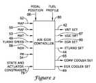
- FIG. 2is a schematic view of an illustrative air-side controller for use with the illustrative diesel engine system of FIG. 1 .
- the illustrative air-side controlleris generally shown at 80 , and receives a number of engine parameters to help provide air-side control to the engine 20 .
- the air-side controller 80receives input signals such as the MAP sensor output 52 , the MAF sensor output 50 , the MAT sensor output 53 , the turbo speed signal 48 , the NOX sensor output 56 and/or the PM sensor output 54 , all shown in FIG. 1 .
- These input parametersare only illustrative, and it is contemplated that more or less input parameters may be received, depending on the application.
- the air-side controller 80may receive a pedal position signal 66 and/or a fuel profile signal as shown, but this is not required or even desired in some embodiments.
- the illustrative air-side controller 80may provide a number of control outputs to help provide air-side control to the engine 20 .
- the air-side controller 80may provide the VNT SET signal 42 , the EGR SET signal 60 , and in some cases, the COMP. COOLER SET signal, the EGR COOLER Set signal, and the ETURBO signal 44 shown in FIG. 1 .
- the air-side controllermay be a multivariable Model Predictive Controller (MPC).
- MPCmay include a model of the dynamic process of engine operation, and provide predictive control signals to the engine subject to constraints in control variables and measured output variables.
- the modelsmay be static and/or dynamic, depending on the application. In some cases, the models produce one or more output signals y(t) from one or more input signals u(t).
- a dynamic modeltypically contains a static model plus information about the time response of the system. Thus, a dynamic model is often of higher fidelity than a static model.
- y(t)which is the output at time t, is based on the current input u(t), one or more past inputs u(t ⁇ 1), . . . u(t ⁇ n), and also on one or more past outputs y(t ⁇ 1) . . . y(t ⁇ m).
- a static model as shownis a simple matrix multiplier.
- a static modeltypically has no “memory” of the inputs u(t ⁇ 1), u(t ⁇ 2) . . . or outputs y(t ⁇ 1) . . . etc. As a result, a static model can be simpler, but may be less powerful in modeling some dynamic system parameters.
- the system dynamicscan be relatively complicated and several of the interactions may have characteristics known as “non-minimum phase”. This is a dynamic response where the output y(t), when exposed to a step in input u(t), will initially move in one direction, and then turn around and move towards its steady state in the opposite direction.
- the soot emission in a diesel engineis just one example.
- these dynamicsmay be important for optimal operation of the control system.
- dynamic modelsare often preferred, at least when modeling some control parameters.
- the MPCmay include a multivariable model that models the effect of changes in one or more actuators of the engine (e.g. VNT SET, EGR SET, COMP COOLER SET, EGR COOLER SET, ETURBO SET, Fueling Rate, etc.) on each of two or more parameters (e.g. AFR, MAP, MAF, NOX, PM), and the multivariable controller may then control the actuators to produce a desired response in the two or more parameters.
- the modelmay, in some cases, model the effects of simultaneous changes in two or more actuators on each of one or more engine parameters, and the multivariable controller may control the actuators to produce a desired response in each of the one or more parameters.
- the variable “y(k)”contains the sensor measurements (for the turbocharger problem, these include but are not limited to MAP, MAF, MAT, turbospeed, NOx emissions, PM emissions, etc).
- t)denote the outputs of the system predicted at time “t+k” when the measurements “y(t)” are available. They are used in the model predictive controller to choose the sequence of inputs which yields the “best” (according to performance index J) predicted sequence of outputs.
- the variables “u(k)”are produced by optimizing J and, in some cases, are used for the actuator set points.
- theseinclude, but are not limited to, the VNT SET, EGR SET, COMP COOLER SET, EGR COOLER SET, ETURBO, etc.
- the variable “x(k)”is a variable representing an internal state of the dynamical state space model of the system.
- t)indicates the predicted version of the state variable k discrete time steps into the future and is used in the model predictive controller to optimize the future values of the system.
- the variables y min and y maxare constraints and indicate the minimum and maximum values that the system predicted measurements ⁇ (k) are permitted to attain. These often correspond to hard limits on the closed-loop behavior in the control system. For example, a hard limit may be placed on the PM emissions such that they are not permitted to exceed a certain number of grams per second at some given time. In some cases, only a minimum y min or maximum y max constraint is provided. For example, a maximum PM emission constraint may be provided, while a minimum PM emission constraint may be unnecessary or undesirable.
- the variables u min and U maxare also constraints, and indicate the minimum and maximum values that the system actuators û(k) are permitted to attain, often corresponding to physical limitations on the actuators.
- the EGR valvemay have a minimum of zero corresponding to a fully closed valve position and a maximum value of one corresponding to the fully open valve position.
- only a minimum u min or maximum u max constraintmay be provided.
- some or all of the constraintse.g. y min , y max , u min , u max ) may vary in time, depending on the current operating conditions.
- the state and actuator constraintsmay be provided to the air-side controller 80 of FIG. 2 via interface 78 , if desired.
- the constant matrices P, Q, Rare often positive definite matrices used to set a penalty on the optimization of the respective variables. These are used in practice to “tune” the closed-loop response of the system.
- FIG. 3is a schematic view of an illustrative model predictive controller in accordance with the present invention.
- the MPC 80includes a State Observer 82 and a MPC Controller 84 .
- the MPC Controller 84provides a number of control outputs “u” to actuators or the like of the engine 20 .
- Illustrative control outputsinclude, for example, the VNT SET signal 42 , the EGR SET signal 60 , the COMP COOLER SET signal 65 , the EGR COOLER SET signal 69 , and the ETURBO SET signal 44 , all shown in FIGS. 1 and 2 .
- the MPC Controller 84may include a memory for storing past values of the control outputs u(t), u(t ⁇ 1), u(t ⁇ 2), etc.
- the State Observer 82receives a number of inputs “y”, a number of control outputs “u”, and a number of internal variables “x”.
- Illustrative inputs “y”include, for example, the MAP sensor output 52 , the MAF sensor output 50 , a Manifold Air Temperature (MAT) signal 53 , the turbo speed signal 48 , the NOX sensor output 56 , and/or the PM sensor output 54 , shown and described above with respect to FIGS. 1 and 2 . It is contemplated that the inputs “y” may be interrogated constantly, intermittently, or periodically, or at any other time, as desired. Also, these input parameters are only illustrative, and it is contemplated that more or less input signals may be provided, depending on the application. In some cases, the State Observer 82 may receive present and/or past values for each of the number of inputs “y”, the number of control outputs “u”, and a number of internal state variables “x”, depending on the application.
- the State Observer 82produces a current set of state variables “x”, which are then provided to the MPC Controller 84 .
- the MPC Controller 84then calculates new control outputs “u”, which are presented to actuators or the like on the engine 20 .
- the control outputs “u”may be updated constantly, intermittently, or periodically, or at any other time, as desired.
- the engine 20operates using the new control outputs “u”, and produces new inputs “y”.
- the MPC 80is programmed using standard Quadratic Programming (QP) and/or Linear Programming (LP) techniques to predict values for the control outputs “u” so that the engine 20 produces inputs “y” that are at a desired target value, within a desired target range, and/or do not violate any predefined constraints.
- QPQuadratic Programming
- LPLinear Programming
- the MPC 80may predict values for the control outputs VNT SET position 42 , EGR SET position 60 and/or the ETURBO SET signal 44 so that future values of the NOX 56 and/or PM emissions signals 54 are at or remain at a desired target value, within a desired target range, and/or do not violate current constraints.
- This prediction capabilitymay be particularly useful since there is often a “turbo lag” (e.g.
- the constraintsmay change, and may depend on the current operating conditions.
- the MPC 80may be implemented in the form of online optimization and/or by using equivalent lookup tables computed with a hybrid multi-parametric algorithm.
- Hybrid multi-parametric algorithmsmay allow constraints on emission parameters as well as multiple system operating modes to be encoded into a lookup table which can be implemented in an Engine Control Unit (ECU) of a vehicle.
- the emission constraintscan be time-varying signals which enter the lookup table as additional parameters.
- Hybrid multi-parametric algorithmare further described by F. Borrelli in “ Constrained Optimal Control of Linear and Hybrid Systems ”, volume 290 of Lecture Notes in Control and Information Sciences, Springer, 2003, which is incorporated herein by reference.
- the MPC 80may include one or more Proportional-Integral-Derivative (PID) control loops, one or more predictive constrained control loops—such as a Smith predictor control loop, one or more multiparametric control loops, one or more multivariable control loops, one or more dynamic matrix control loops, one or more statistical processes control loop, a knowledge based expert system, a neural network, fuzzy logic or any other suitable control mechanism, as desired.
- PIDProportional-Integral-Derivative
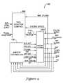
- FIG. 4is a schematic view of another illustrative diesel engine system in accordance with the present invention.
- This illustrative diesel engine systemis generally shown at 100 , and includes a diesel engine 102 that includes a variable nozzle turbine (VNT) turbocharger with electric motor assist and an Exhaust Gas Recirculation (EGR) Valve that is inserted between the engines' exhaust manifold and the intake manifold.
- VNTvariable nozzle turbine
- EGRExhaust Gas Recirculation
- a number of sensor outputsare provided for monitoring various parameters of the engine during operation.
- the illustrative sensor outputsinclude, for example, an engine speed parameter, an intake manifold air pressure (MAP) parameter, an intake manifold air flow (MAF) parameter, a turbo speed parameter, an NOX parameter and a PM parameter, as shown.
- MAPintake manifold air pressure
- MAFintake manifold air flow
- a fuel injector controller 106is provided for controlling the fuel that is injected into the engine.
- the illustrative fuel injector controller 106may include an air-fuel-ratio (AFR) estimator that receives the intake manifold air flow (MAF) parameter and a fuel rate parameter to estimate the air-fuel-ratio (AFR) going into the engine.
- AFRair-fuel-ratio
- the air-fuel-ratio (AFR) estimatormay keep the estimated AFR above a minimum AFR LOW LIMIT value, which if may help reduce smoke or other undesirable emissions that may occur at low AFR values.
- the fuel injector controller 106may control the fuel rate delivered by the fuel injectors to the engine.
- a pedal position signal and an engine speed signalare used to calculate the desired amount of fuel for the engine.
- stepping on the pedalincreases the fuel flow in a manner dictated by one or more static and/or dynamic control maps.
- an air side controller 108may also be provided.
- the air side controller 108may receive a number of engine parameters to help provide air-side control to the engine 102 .
- the term “air-side control”may include both intake air and exhaust or emission control.
- the air-side controller 108may receive input signals such as the MAP sensor output, the MAF sensor output, the MAT sensor output, the turbo speed signal, the NOX sensor output and the PM sensor output. These input parameters are only illustrative, and it is contemplated that more or less input signals may be received, depending on the application.
- the air side controller 108does not receive a measure of the fueling profile 116 provided by the fuel injector controller 106 . In other embodiments, however, such as those shown and described below with respect to FIGS. 11-14 , the air side controller may receive a measure of the fueling profile as an input.
- the illustrative air-side controller 108may provide a number of control outputs to help provide air-side control to the engine 102 .
- the air-side controller 108may provide a VNT SET signal, an EGR SET signal, a VGC SET signal, an ETURBO SET signal, a COMP COOLER SET signal, an EGR COOLER SET signal, etc.
- the air side controller 108may be similar to the air side controller 80 of FIG. 2 .
- FIG. 5is a schematic view of a prior art speed controller 126 which is conventionally used for controlling the fuel rate delivered by the fuel injectors to an engine.
- the speed controller 126receives a pedal position signal 127 and a measured engine speed signal 129 , both of which are functions of time.
- a pedal position signal 127may be provided to a static map 128 , which is a table that relates the pedal position to an engine speed set point 130 .
- the engine speed set point 130is compared to the measured engine speed signal 129 , and an offset signal 134 is provided to a speed control block 136 .
- the speed control block 136uses the offset signal, the speed control block 136 then provides a fueling rate signal 138 to one or more of the fuel injectors of the engine.
- the speed controller 136may contain a fuel rate limiter designed to maintain the AFR>AFR LOW LIMIT.
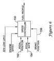
- FIG. 6is a schematic view of a speed controller in accordance with one illustrative embodiment of the present invention.
- the speed controller 150may receive both a pedal position signal 152 and a pedal change rate signal 154 .
- the speed controller 150may anticipate future fuel and/or air needs of the engine, and may adjust the fuel profile and/or air profile to meet those anticipated needs.
- the speed controller 150may provide a larger fueling rate for a given pedal position when the pedal change rate is positive and higher than when the pedal change rate is positive and smaller. Likewise, the speed controller 150 may provide a smaller fueling rate for a given pedal position when the pedal change rate is negative and higher than when the pedal change rate is negative and smaller. Similarly, the speed controller 150 may provide a larger turbo boost (MAP) for a given pedal position when the pedal change rate is positive and higher than when the pedal change rate is positive and smaller. Likewise, the speed controller 150 may provide a smaller turbo boost (MAP) for a given pedal position when the pedal change rate is negative and higher than when the pedal change rate is negative and smaller. EGR and other engine parameters may be controlled in a similar manner.
- MAPturbo boost
- EGR and other engine parametersmay be controlled in a similar manner.
- the speed controller 150may receive a brake position signal 156 .
- Brake pedal sensingmay be used to anticipate future fuel side needs of the engine. For example, when a driver removes pressure from a brake pedal, it may be reasonable to assume that pressure will soon be applied to the fuel pedal.
- the speed controller 150may use the brake position signal 156 to help anticipate future fuel needs.
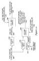
- FIG. 7is a schematic view of another illustrative speed controller in accordance with the present invention.
- a pedal position signal 160is provided to a first dynamic map 162 .
- the first dynamic map 162may translate the pedal position and a pedal change rate (and in some cases, further derivatives of the pedal position), and provide a corresponding engine speed set point 170 .
- the first dynamic map 162may help anticipate an acceleration of the engine and increase the current engine speed set point 170 , when the pedal change rate is positive.
- the first dynamic map 162may anticipate a deceleration and decrease the current engine speed set point 170 , when the pedal change rate is negative.
- the engine speed set point 170is compared to a measured engine speed signal 172 via comparator 174 , and an offset signal 175 is provided to a speed control block 176 .
- the speed control block 176uses the offset signal 175 to provide a fueling rate signal 178 to one or more of the fuel injectors of the engine.
- the speed controller 176may also receive an AFR LOW LIMIT signal 180 .
- the AFR LOW LIMIT signal 180may be set to a value that if the estimated AFR of the engine falls below the AFR LOW LIMIT signal 180 value, smoke or other undesirable emissions may be expected to appear in the engine exhaust.
- the speed controller 176may reduce the fuel rate 178 to at least temporarily increase the AFR provided to the engine.
- FIG. 8is a chart showing an engine speed set point response of a speed controller that has a dynamic map versus a static map.
- An input pedal position signalis shown at 214 , which includes a step 214 a that rises from a lower position to a higher position.
- the corresponding engine speed set point 130 produced by the static map 128may have a step 130 a that corresponds to the step in the input pedal position signal 214 , as shown in FIG. 8 .
- the corresponding step 130 a in the engine speed signal 130is merely reactive, and does not include any information or anticipate future needs of the engine.
- the corresponding engine speed set point 170may have a corresponding step 170 a that has a higher initial amplitude than the step 130 produced by the static map, followed by a decay region 170 b in the engine speed set point 170 , eventually leveling out at a level that is similar to that produced by the static map 128 (see FIG. 8 ).
- the engine speed set point 170may include information and/or anticipate future needs of the engine, and produce an engine speed set point 170 that attempts to satisfy those future needs.
- the dynamic map 162may translate the pedal position and a pedal change rate (and in some cases, further derivatives of the pedal position), and provide a corresponding engine speed set point 170 .
- the dynamic map 162may help anticipate an acceleration of the engine and/or a deceleration of the engine, and produce an engine speed set point 170 that attempts to satisfy the anticipated future needs of the engine. This may, for example, help increase the performance and/or reduce the emissions of the engine.
- a combination of dynamic maps and look up tablesmay be used.
- a first dynamic map, followed by a look up table, followed by a second dynamic mapmay be used.
- the first dynamic mapmay function as, for example, a pre-filter for the signal(s) entering the look up table
- the second dynamic mapmay function as a post filter for the signal(s) leaving the look up table.
- the first dynamic filtermay be a Kalman filter, an extended Kalman filter or any state observer filter
- the second dynamic filtermay be the identity filter.
- the look up tablemay be computed using any suitable method, but in some cases, using optimal or sub-optimal multi-parametric hybrid algorithms discussed above. Consistent with the multi-parametric hybrid algorithms, the lookup table may encode constraints on emission parameters in multiple engine operating modes, and may generate one or more engine control signals that are adapted to keep the engine emission or other parameters within the assigned constraints for the designated engine operating modes. In some embodiments, the look up table may accept emission control constraints as input parameters.
- the emission control constraintscan be static or time-varying, and can be computed offline for a given set of engine operating modes, or in real or near real time, depending on the application.
- FIG. 9is a schematic view of another illustrative engine controller in accordance with the present invention.
- the illustrative engine controller of FIG. 9is the same as the illustrative embodiment shown in FIG. 7 , but provides the pedal position to an air-side controller 204 of the engine.
- the pedal position signal 160is provides to a second dynamic (or static) map 202 , which relates information about the pedal position (e.g. pedal position, pedal change rate, etc.) to one or more air side control parameters.
- the air side controller 204may provide one or more control signals to help control the air side of the engine.
- the air side control signalsmay include, for example, a VNT SET signal 206 , an EGR SET signal 208 , a VGC SET signal 218 , an ETURBO SET signal 210 , a COMP COOLER SET signal 220 , EGR COOLER SET signal 222 , and/or any other suitable signal, as desired.
- the air side controller 204may receive a number of other input signals 212 such as a MAP signal, a MAF signal, a MAT signal, a turbo speed signal, a NOX signal, a PM signal, and/or any other suitable signal, as desired.
- a number of other input signals 212such as a MAP signal, a MAF signal, a MAT signal, a turbo speed signal, a NOX signal, a PM signal, and/or any other suitable signal, as desired.
- some or all of the air side control signalsmay be adjusted to anticipate needed changes to improve engine response time, performance and/or emissions.
- the air side controller 204may anticipate that extra turbo boost will be necessary and may change the VNT SET signal 206 and/or VGC SET signal 218 to immediately begin providing the anticipated turbo boost with little or no delay.
- the EGR SET signal 208 , ETURBO SET signal 210 , COMP COOLER SET signal 220 , EGR COOLER SET signal 222 , and/or any other control signal provided by the air side controller 204may likewise be adjusted to cancel or otherwise compensate for disrupting effects caused by changes in pedal position and/or pedal change rate. This may help improve the responsiveness, performance and/or emissions of the engine.
- the number of other input signals 212may include a brake position signal.
- Brake pedal sensingmay be used to anticipate future air side needs of the engine. For example, when a driver removes pressure from a brake pedal, it may be reasonable to assume that pressure will soon be applied to the fuel pedal.
- the air side controller 204may use the brake position signal to help anticipate future air side needs.
- FIG. 10is a schematic view of another illustrative engine controller in accordance with the present invention.
- the pedal position 240is provided to a fuel side position and rate map 242 and an air side position and rate map 250 .
- the rate maps 242 and 250may be dynamic maps, static maps, or combinations thereof.
- the fuel side rate map 242may translate the pedal position and/or pedal change rate (and in some cases, further derivatives of the pedal position) into one or more fuel side set points 243 .
- a fuel side controller 244receives the fuel side set points 243 , along with a number of fuel side sensor outputs 246 such as engine speed, MAF, MAP, MAT, etc., and provides a fueling profile 248 to the fuel injectors of the engine.
- the air side rate map 250may translate the pedal position and/or pedal change rate (and in some cases, further derivatives of the pedal position) into one or more air side parameters.
- Another air side set point map 252may receive a number of other engine parameters 254 such as, a brake parameter, a temperature parameter, an outside air pressure parameter, a humidity parameter and/or any other suitable parameters, and may provide one or more air side set points.
- the air side set point map 252may be a dynamic or static map, as desired.
- An air side controller 256receives the one or more air side parameters from the air side rate map 250 , and in some cases, the one or more air side set points from the air side set point map 252 , along with one or more air side sensor output signals such as MAP, MAF, MAT, NOX, PM, turbo speed, VNT POS, EGR POS, etc., and provide one or more air side control signals, such as VNT SET, EGR SET, VGC SET, ETURBO SET, COMP COOLER SET, EGR COOLER SET, and/or any other suitable control signal, as desired.
- one or more air side sensor output signalssuch as MAP, MAF, MAT, NOX, PM, turbo speed, VNT POS, EGR POS, etc.
- air side control signalssuch as VNT SET, EGR SET, VGC SET, ETURBO SET, COMP COOLER SET, EGR COOLER SET, and/or any other suitable control signal, as desired.
- FIG. 11is a schematic view of another illustrative diesel engine system in accordance with the present invention.
- This illustrative diesel engine systemis generally shown at 300 , and includes a diesel engine 302 that includes a variable nozzle turbine (VNT) turbocharger with electric motor assist and an Exhaust Gas Recirculation (EGR) Valve that is inserted between the engines' exhaust manifold and the engine's intake manifold.
- the illustrative diesel engine 302also includes a variable geometry compressor (VGC), where in some cases, a VGC SET signal is used to set the vane position at the outlet of the compressor to provide a controlled amount of compressed air to the intake manifold 22 .
- VGCvariable geometry compressor
- a number of sensor outputsare provided for monitoring various parameters of the engine during operation.
- the illustrative sensor outputsinclude an engine speed parameter, an intake manifold air pressure (MAP) parameter, an intake manifold air flow (MAF) parameter, a turbo speed parameter, an NOX parameter and a PM parameter, as shown. More or less sensor outputs may be provided, if desired.
- a fuel injector controller 306is provided for controlling the fuel that is injected into the engine.
- the illustrative fuel injector controller 306may be similar to the fuel injector controller 106 described above with reference of FIG. 4 .
- the illustrative fuel injector controller 306may include an air-fuel-ratio (AFR) estimator that receives the intake manifold air flow (MAF) parameter and a fuel rate parameter to estimate the air-fuel-ratio (AFR) going into the engine.
- the air-fuel-ratio (AFR) estimatormay keep the estimated AFR above a minimum AFR LOW LIMIT value, which if may help reduce smoke or other undesirable emissions that may occur at low AFR values.
- the fuel injector controller 306may control the fuel rate delivered by the fuel injectors to the engine.
- a pedal position signal, a pedal rate signal, and an engine speed signalare used to calculate the desired amount of fuel for the engine.
- stepping on the pedalincreases the fuel flow in a manner dictated by one or more static and/or dynamic control maps, as further described above.
- an air side controller 320is also provided.
- the air side controller 320receives a number of engine parameters to help provide air-side control to the engine 302 .
- the air-side controller 320may receive input signals such as a MAP sensor output, a MAF sensor output, a turbo speed signal, a NOX sensor output and/or a PM sensor output, as shown. These input parameters are only illustrative, and it is contemplated that more or less input signals may be received, depending on the application.
- the air side controller 320also receives one or more fuel profile signals 314 , which provide information related to the fuel profile that is currently provided to the engine 302 . Based on the value of the received input parameters, including the fuel profile signal(s) 314 , the illustrative air-side controller 320 provides a number of control outputs to help provide air-side control to the engine 302 .
- the air-side controller 320may provide a VNT SET signal 324 , an VGC SET signal 330 , an EGR SET signal 326 , an ETURBO SET signal 328 , a COMP COOLER SET signal 332 and/or an EGR COOLER SET signal 334 .
- Other control signalsmay also be provided by the air side controller 320 , if desired.
- the air side controller 320may adjust one or more control signals such as VNT SET signal 324 , VGC SET signal 330 , EGR SET signal 326 , the ETURBO SET signal 328 , the COMP COOLER SET signal 332 and/or the EGR COOLER SET signal 334 , to cancel or mitigate disrupting effects on, for example, MAP, MAF, turbo speed, NOX emissions, PM emissions, etc. This may help improve the responsiveness, performance and/or emissions of the engine.
- FIG. 12is a schematic view of another illustrative air-side controller in accordance with the present invention.
- the illustrative air-side controller 340receives a fuel profile signal 342 along with one or more other parameters 344 .
- the fuel profile signal 342may include any number of fuel characteristics such as fuel delivery rate, change in fuel delivery rate, fuel timing, fuel pre-injection event(s), fuel post-injection event(s), fuel pulses, and/or any other fuel delivery characteristic, as desired.
- the one or more other parameters 344may include, for example, a MAP parameter, a MAF parameter, a turbo speed parameter, a NOX parameter, a PM parameter, an engine speed parameter, a VNT position parameter, an EGR position parameter, a brake position parameter, an outside temperature parameter, an outside air pressure parameter, a humidity parameter and/or any other parameter, as desired.
- the illustrative air-side controller 340then provides one or more air side control signals to an engine.
- the air-side controller 340may provide a VNT SET signal 346 , a VGC SET signal 352 , an EGR SET signal 348 , an ETURBO SET signal 350 , a COMP COOLER SET signal 354 , an EGR COOLER SET signal 356 and/or any other air-side control signal, as desired.
- the air-side controller 340may be implemented in the form of online optimization and/or by using equivalent lookup tables computed with a hybrid multi-parametric algorithm.
- Hybrid multi-parametric algorithmsmay allow constraints on emission parameters as well as multiple system operating modes to be encoded into a lookup table which can be implemented in an Engine Control Unit (ECU) of a vehicle.
- the emission constraintscan be time-varying signals which enter the lookup table as additional parameters.
- Hybrid multi-parametric algorithmare further described by F. Borrelli in “ Constrained Optimal Control of Linear and Hybrid Systems ”, volume 290 of Lecture Notes in Control and Information Sciences, Springer, 2003, which is incorporated herein by reference.
- the air-side controller 340may include one or more Proportional-Integral-Derivative (PID) control loops, one or more predictive constrained control loops—such as a Smith predictor control loop, one or more multiparametric control loops, one or more multivariable control loops, one or more dynamic matrix control loops, one or more statistical processes control loop, a knowledge based expert system, a neural network, fuzzy logic or any other suitable control mechanism, as desired.
- PIDProportional-Integral-Derivative
- the air side controller 340may provide commands and/or set points for lower-level controllers that are used to control the actuators of the engine.
- the lower level controllersmay be, for example, single-input-single-output (SISO) controllers such as PID controllers.
- SISOsingle-input-single-output
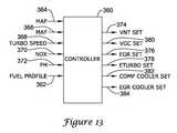
- FIG. 13is a schematic view of another illustrative air-side controller in accordance with the present invention.
- the illustrative air-side controller 360receives a fuel profile signal 362 .
- the fuel profile signal 362may include any number of fuel characteristics such as fuel delivery rate, change in fuel delivery rate, fuel timing, fuel pre-injection event(s), fuel post-injection event(s), fuel pulses, and/or any other fuel delivery characteristic, as desired.
- the illustrative air-side controller 360may also receive other engine parameters including, for example, a MAP parameter 364 , a MAF parameter 366 , a turbo speed parameter 368 , a NOX parameter 370 , a PM parameter 372 and/or any other parameter, as desired.
- the illustrative air-side controller 360then provides one or more air side control signals to an engine.
- the air-side controller 360may provide a VNT SET signal 374 , a VGC SET signal 380 , an EGR SET signal 376 , an ETURBO SET signal 378 , a COMP COOLER SET signal 382 and/or an EGR COOLER SET signal 384 and/or any other air-side control signal, as desired.
- the air-side controller 360may be implemented in the form of online optimization and/or by using equivalent lookup tables computed with a hybrid multi-parametric algorithm.
- Hybrid multi-parametric algorithmsmay allow constraints on emission parameters as well as multiple system operating modes to be encoded into a lookup table which can be implemented in an Engine Control Unit (ECU) of a vehicle.
- the emission constraintscan be time-varying signals which enter the lookup table as additional parameters.
- Hybrid multi-parametric algorithmare further described by F. Borrelli in “ Constrained Optimal Control of Linear and Hybrid Systems ”, volume 290 of Lecture Notes in Control and Information Sciences, Springer, 2003, which is incorporated herein by reference.
- the air-side controller 360may include one or more Proportional-Integral-Derivative (PID) control loops, one or more predictive constrained control loops—such as a Smith predictor control loop, one or more multiparametric control loops, one or more multivariable control loops, one or more dynamic matrix control loops, one or more statistical processes control loop, a knowledge based expert system, a neural network, fuzzy logic or any other suitable control mechanism, as desired.
- PIDProportional-Integral-Derivative
- the air side controller 360may provide commands and/or set points for lower-level controllers that are used to control the actuators of the engine.
- the lower level controllersmay be, for example, single-input-single-output (SISO) controllers such as PID controllers.
- SISOsingle-input-single-output
- FIG. 14is a schematic view of another illustrative air-side controller in accordance with the present invention.
- the illustrative air-side controlleris generally shown at 384 .
- a pedal position signal 402is provided to a Fuel Side Controller 406 .
- the Fuel Side Controller 406receives a number of input parameters such as an engine speed parameter, a MAF parameter, etc. via interface 408 . Uses the pedal position signal 402 and the number of input parameters 408 , the Fuel Side Controller 406 provides one or more fuel control signals 410 to one or more fuel side actuators, such as fuel injectors.
- one or more of the fuel control signals 410are also provided to an Air Side Controller 414 as an input measured disturbance.
- the illustrative Air Side Controller 414also receives a number of input signals from air side sensors via interface 420 .
- the air side sensorsmay include, for example, a MAP sensor, a MAF sensor, a MAT sensor, a NOX sensor, a PM sensor, a turbo speed sensor, an engine speed sensor, and/or any other type of sensor, as desired.
- the illustrative Air Side Controller 414may also receive a number of other air-side set points 417 from a Set Point Map 416 .
- the Set Point Map 416may translate one or more other engine parameters 418 into the one or more air side set points 417 .
- the one or more other engine parametersmay include, for example, a brake parameter, a temperature parameter, an outside air pressure parameter, a humidity parameter and/or any other desired engine parameter.
- the Set Point Map 416may be a dynamic or static map, as desired
- the illustrative Air Side Controller 414may provide one or more air side control signals 422 .
- the Air Side Controller 414may provide a VNT SET signal, a VGC SET signal, an EGR SET signal, an ETURBO SET signal, a COMP COOLER SET signal, an EGR COOLER SET signal and/or any other air-side control signal, as desired.
- the illustrative embodimentmay be capable of, for example, anticipating an acceleration and/or deceleration (e.g. via increased fuel rate 410 ), and then increase/decease the air delivery rate to the engine with little or no delay to help improve the responsiveness, performance and/or emissions of the engine.
Landscapes
- Engineering & Computer Science (AREA)
- Chemical & Material Sciences (AREA)
- Combustion & Propulsion (AREA)
- Mechanical Engineering (AREA)
- General Engineering & Computer Science (AREA)
- Output Control And Ontrol Of Special Type Engine (AREA)
- Combined Controls Of Internal Combustion Engines (AREA)
- Electrical Control Of Air Or Fuel Supplied To Internal-Combustion Engine (AREA)
Abstract
Description
y(t)=B0*u(t)+B1*u(t−1)+ . . . +Bn*u(t−n)+A1*y(t−1)+ . . . +Am*y(t−m)
where B0 . . . Bn, and A1 . . . Am are constant matrices. In a dynamic model, y(t) which is the output at time t, is based on the current input u(t), one or more past inputs u(t−1), . . . u(t−n), and also on one or more past outputs y(t−1) . . . y(t−m).
y(t)=B0u(t)
A static model as shown is a simple matrix multiplier. A static model typically has no “memory” of the inputs u(t−1), u(t−2) . . . or outputs y(t−1) . . . etc. As a result, a static model can be simpler, but may be less powerful in modeling some dynamic system parameters.
x(t+1)=Ax(t)+Bu(t)
y(t)=Cx(t)
The model predictive algorithm involves solving the problem:
u(k)=arg min{J}
Where the function J is given by,
Subject to Constraints
ymin≦ŷ(t+k|t)≦ymax
umin≦u(t+k)≦umax
x(t|t)=x(t)
{circumflex over (x)}(t+k+1|t)=A{circumflex over (x)}(t+k|t)+Bu(t+k)
ŷ(t+k|t)=C{circumflex over (x)}(t+k|t)
In some embodiments, this is transformed into a Quadratic Programming (QP) problem and solved with standard or customized tools.
Claims (7)
Priority Applications (2)
| Application Number | Priority Date | Filing Date | Title |
|---|---|---|---|
| US11/616,977US7591135B2 (en) | 2004-12-29 | 2006-12-28 | Method and system for using a measure of fueling rate in the air side control of an engine |
| PCT/US2007/087734WO2008082932A1 (en) | 2006-12-28 | 2007-12-17 | Method and system for using a measure of fueling rate in the air side control of an engine |
Applications Claiming Priority (2)
| Application Number | Priority Date | Filing Date | Title |
|---|---|---|---|
| US11/025,563US7165399B2 (en) | 2004-12-29 | 2004-12-29 | Method and system for using a measure of fueling rate in the air side control of an engine |
| US11/616,977US7591135B2 (en) | 2004-12-29 | 2006-12-28 | Method and system for using a measure of fueling rate in the air side control of an engine |
Related Parent Applications (1)
| Application Number | Title | Priority Date | Filing Date |
|---|---|---|---|
| US11/025,563ContinuationUS7165399B2 (en) | 2004-12-29 | 2004-12-29 | Method and system for using a measure of fueling rate in the air side control of an engine |
Publications (2)
| Publication Number | Publication Date |
|---|---|
| US20070101977A1 US20070101977A1 (en) | 2007-05-10 |
| US7591135B2true US7591135B2 (en) | 2009-09-22 |
Family
ID=39226002
Family Applications (1)
| Application Number | Title | Priority Date | Filing Date |
|---|---|---|---|
| US11/616,977Expired - LifetimeUS7591135B2 (en) | 2004-12-29 | 2006-12-28 | Method and system for using a measure of fueling rate in the air side control of an engine |
Country Status (2)
| Country | Link |
|---|---|
| US (1) | US7591135B2 (en) |
| WO (1) | WO2008082932A1 (en) |
Cited By (56)
| Publication number | Priority date | Publication date | Assignee | Title |
|---|---|---|---|---|
| US20090264251A1 (en)* | 2008-04-18 | 2009-10-22 | Robert Paul Bertsch | Machine control system with directional shift management |
| US20090266151A1 (en)* | 2008-04-28 | 2009-10-29 | Wilhelm Blumendeller | Method and Device for Adapting the Efficiency of a Cooler in the Return Circuit of Exhaust Gas in an Internal Combustion Engine |
| US20100179726A1 (en)* | 2007-07-16 | 2010-07-15 | Knorr-Bremse Systeme Fuer Nutzfahrzeuge Gmbh | Apparatus and Method for Identifying in Advance Overrun Phases of a Vehicle |
| US8265854B2 (en) | 2008-07-17 | 2012-09-11 | Honeywell International Inc. | Configurable automotive controller |
| US8360040B2 (en) | 2005-08-18 | 2013-01-29 | Honeywell International Inc. | Engine controller |
| US8437941B2 (en) | 2009-05-08 | 2013-05-07 | Gas Turbine Efficiency Sweden Ab | Automated tuning of gas turbine combustion systems |
| US8504175B2 (en) | 2010-06-02 | 2013-08-06 | Honeywell International Inc. | Using model predictive control to optimize variable trajectories and system control |
| USRE44452E1 (en) | 2004-12-29 | 2013-08-27 | Honeywell International Inc. | Pedal position and/or pedal change rate for use in control of an engine |
| US20130297185A1 (en)* | 2012-05-02 | 2013-11-07 | Andrew A. Morris | Driver-assisted fuel reduction strategy and associated apparatus, system, and method |
| US8620461B2 (en) | 2009-09-24 | 2013-12-31 | Honeywell International, Inc. | Method and system for updating tuning parameters of a controller |
| US20140148928A1 (en)* | 2012-11-27 | 2014-05-29 | Honeywell International Inc. | Multivariable control system for setpoint design |
| US9145856B2 (en) | 2010-10-22 | 2015-09-29 | Ecomplete, Llc | Systems and methods for high efficiency reliable catalyst delivery to internal combustion engines |
| US9235657B1 (en) | 2013-03-13 | 2016-01-12 | Johnson Controls Technology Company | System identification and model development |
| US9267443B2 (en) | 2009-05-08 | 2016-02-23 | Gas Turbine Efficiency Sweden Ab | Automated tuning of gas turbine combustion systems |
| US9347401B2 (en) | 2012-10-18 | 2016-05-24 | Cummins Inc. | Lambda feedback control for robust particulate emissions performance |
| US9354618B2 (en) | 2009-05-08 | 2016-05-31 | Gas Turbine Efficiency Sweden Ab | Automated tuning of multiple fuel gas turbine combustion systems |
| US9436179B1 (en) | 2013-03-13 | 2016-09-06 | Johnson Controls Technology Company | Systems and methods for energy cost optimization in a building system |
| US9650934B2 (en) | 2011-11-04 | 2017-05-16 | Honeywell spol.s.r.o. | Engine and aftertreatment optimization system |
| US9671797B2 (en) | 2009-05-08 | 2017-06-06 | Gas Turbine Efficiency Sweden Ab | Optimization of gas turbine combustion systems low load performance on simple cycle and heat recovery steam generator applications |
| US9677493B2 (en) | 2011-09-19 | 2017-06-13 | Honeywell Spol, S.R.O. | Coordinated engine and emissions control system |
| US9852481B1 (en) | 2013-03-13 | 2017-12-26 | Johnson Controls Technology Company | Systems and methods for cascaded model predictive control |
| US10036338B2 (en) | 2016-04-26 | 2018-07-31 | Honeywell International Inc. | Condition-based powertrain control system |
| US10101730B2 (en) | 2014-05-01 | 2018-10-16 | Johnson Controls Technology Company | Incorporating a load change penalty in central plant optimization |
| US10124750B2 (en) | 2016-04-26 | 2018-11-13 | Honeywell International Inc. | Vehicle security module system |
| US10186889B2 (en) | 2015-10-08 | 2019-01-22 | Taurus Des, Llc | Electrical energy storage system with variable state-of-charge frequency response optimization |
| US20190024576A1 (en)* | 2017-07-18 | 2019-01-24 | Ford Global Technologies, Llc | Transient compensation for variable geometry compressor |
| US10190793B2 (en) | 2015-10-08 | 2019-01-29 | Johnson Controls Technology Company | Building management system with electrical energy storage optimization based on statistical estimates of IBDR event probabilities |
| US10190789B2 (en) | 2015-09-30 | 2019-01-29 | Johnson Controls Technology Company | Central plant with coordinated HVAC equipment staging across multiple subplants |
| US10197632B2 (en) | 2015-10-08 | 2019-02-05 | Taurus Des, Llc | Electrical energy storage system with battery power setpoint optimization using predicted values of a frequency regulation signal |
| US10222427B2 (en) | 2015-10-08 | 2019-03-05 | Con Edison Battery Storage, Llc | Electrical energy storage system with battery power setpoint optimization based on battery degradation costs and expected frequency response revenue |
| US10235479B2 (en) | 2015-05-06 | 2019-03-19 | Garrett Transportation I Inc. | Identification approach for internal combustion engine mean value models |
| US10250039B2 (en) | 2015-10-08 | 2019-04-02 | Con Edison Battery Storage, Llc | Energy storage controller with battery life model |
| US10272779B2 (en) | 2015-08-05 | 2019-04-30 | Garrett Transportation I Inc. | System and approach for dynamic vehicle speed optimization |
| US10283968B2 (en) | 2015-10-08 | 2019-05-07 | Con Edison Battery Storage, Llc | Power control system with power setpoint adjustment based on POI power limits |
| US10309287B2 (en) | 2016-11-29 | 2019-06-04 | Garrett Transportation I Inc. | Inferential sensor |
| US10389136B2 (en) | 2015-10-08 | 2019-08-20 | Con Edison Battery Storage, Llc | Photovoltaic energy system with value function optimization |
| US10418832B2 (en) | 2015-10-08 | 2019-09-17 | Con Edison Battery Storage, Llc | Electrical energy storage system with constant state-of charge frequency response optimization |
| US10418833B2 (en) | 2015-10-08 | 2019-09-17 | Con Edison Battery Storage, Llc | Electrical energy storage system with cascaded frequency response optimization |
| US10415492B2 (en) | 2016-01-29 | 2019-09-17 | Garrett Transportation I Inc. | Engine system with inferential sensor |
| US10423131B2 (en) | 2015-07-31 | 2019-09-24 | Garrett Transportation I Inc. | Quadratic program solver for MPC using variable ordering |
| US10503128B2 (en) | 2015-01-28 | 2019-12-10 | Garrett Transportation I Inc. | Approach and system for handling constraints for measured disturbances with uncertain preview |
| US10554170B2 (en) | 2015-10-08 | 2020-02-04 | Con Edison Battery Storage, Llc | Photovoltaic energy system with solar intensity prediction |
| US10564610B2 (en) | 2015-10-08 | 2020-02-18 | Con Edison Battery Storage, Llc | Photovoltaic energy system with preemptive ramp rate control |
| US10594153B2 (en) | 2016-07-29 | 2020-03-17 | Con Edison Battery Storage, Llc | Frequency response optimization control system |
| US10621291B2 (en) | 2015-02-16 | 2020-04-14 | Garrett Transportation I Inc. | Approach for aftertreatment system modeling and model identification |
| US10700541B2 (en) | 2015-10-08 | 2020-06-30 | Con Edison Battery Storage, Llc | Power control system with battery power setpoint optimization using one-step-ahead prediction |
| US10742055B2 (en) | 2015-10-08 | 2020-08-11 | Con Edison Battery Storage, Llc | Renewable energy system with simultaneous ramp rate control and frequency regulation |
| US10778012B2 (en) | 2016-07-29 | 2020-09-15 | Con Edison Battery Storage, Llc | Battery optimization control system with data fusion systems and methods |
| US10815926B2 (en) | 2018-11-30 | 2020-10-27 | Hyundai Motor Company | Engine control method for vehicle |
| US10838440B2 (en) | 2017-11-28 | 2020-11-17 | Johnson Controls Technology Company | Multistage HVAC system with discrete device selection prioritization |
| US10838441B2 (en) | 2017-11-28 | 2020-11-17 | Johnson Controls Technology Company | Multistage HVAC system with modulating device demand control |
| US11057213B2 (en) | 2017-10-13 | 2021-07-06 | Garrett Transportation I, Inc. | Authentication system for electronic control unit on a bus |
| US11156180B2 (en) | 2011-11-04 | 2021-10-26 | Garrett Transportation I, Inc. | Integrated optimization and control of an engine and aftertreatment system |
| US11159022B2 (en) | 2018-08-28 | 2021-10-26 | Johnson Controls Tyco IP Holdings LLP | Building energy optimization system with a dynamically trained load prediction model |
| US11163271B2 (en) | 2018-08-28 | 2021-11-02 | Johnson Controls Technology Company | Cloud based building energy optimization system with a dynamically trained load prediction model |
| US11210617B2 (en) | 2015-10-08 | 2021-12-28 | Johnson Controls Technology Company | Building management system with electrical energy storage optimization based on benefits and costs of participating in PDBR and IBDR programs |
Families Citing this family (14)
| Publication number | Priority date | Publication date | Assignee | Title |
|---|---|---|---|---|
| WO2007098780A1 (en)* | 2006-02-28 | 2007-09-07 | Bayerische Motoren Werke Aktiengesellschaft | Method for regulating the fuel-air mixture in an internal combustion engine |
| JP2009221881A (en)* | 2008-03-13 | 2009-10-01 | Yanmar Co Ltd | Engine |
| DE102008035985B4 (en)* | 2008-08-01 | 2010-07-08 | Continental Automotive Gmbh | Method and device for regulating the fuel pressure in the pressure accumulator of a common rail injection system |
| JP5249898B2 (en)* | 2009-09-29 | 2013-07-31 | 富士通株式会社 | Engine control program, method and apparatus |
| ITBO20120216A1 (en) | 2012-04-19 | 2013-10-20 | Magneti Marelli Spa | METHOD OF CONTROL OF AN INTERNAL COMBUSTION ENGINE |
| US9382835B2 (en)* | 2012-06-15 | 2016-07-05 | Ford Global Technologies, Llc | Internal combustion engine having a direct injection system and having a port fuel injection system |
| US9784198B2 (en)* | 2015-02-12 | 2017-10-10 | GM Global Technology Operations LLC | Model predictive control systems and methods for increasing computational efficiency |
| US9989001B2 (en)* | 2012-12-21 | 2018-06-05 | Toyota Motor Engineering & Manufacturing North America, Inc. | Discrete time rate-based model predictive control method for internal combustion engine air path control |
| US20160131089A1 (en) | 2014-11-12 | 2016-05-12 | Deere And Company | Variable geometry turbocharger feed forward control system and method |
| US20160131057A1 (en) | 2014-11-12 | 2016-05-12 | Deere And Company | Fresh air flow and exhaust gas recirculation control system and method |
| US9835094B2 (en)* | 2015-08-21 | 2017-12-05 | Deere & Company | Feed forward exhaust throttle and wastegate control for an engine |
| US10145320B1 (en)* | 2017-08-31 | 2018-12-04 | Ford Global Technologies, Llc | Methods and systems for boost and EGR control |
| US10995688B2 (en)* | 2019-06-04 | 2021-05-04 | GM Global Technology Operations LLC | Method and system for determining thermal state |
| US11454180B1 (en) | 2021-06-17 | 2022-09-27 | Cummins Inc. | Systems and methods for exhaust gas recirculation |
Citations (187)
| Publication number | Priority date | Publication date | Assignee | Title |
|---|---|---|---|---|
| US3744461A (en) | 1970-09-04 | 1973-07-10 | Ricardo & Co Eng 1927 Ltd | Method and means for reducing exhaust smoke in i.c.engines |
| US3969614A (en)* | 1973-12-12 | 1976-07-13 | Ford Motor Company | Method and apparatus for engine control |
| US4005578A (en) | 1975-03-31 | 1977-02-01 | The Garrett Corporation | Method and apparatus for turbocharger control |
| US4055158A (en) | 1974-04-08 | 1977-10-25 | Ethyl Corporation | Exhaust recirculation |
| US4138979A (en)* | 1977-09-29 | 1979-02-13 | The Bendix Corporation | Fuel demand engine control system |
| US4252098A (en) | 1978-08-10 | 1981-02-24 | Chrysler Corporation | Air/fuel ratio control for an internal combustion engine using an exhaust gas sensor |
| US4383441A (en) | 1981-07-20 | 1983-05-17 | Ford Motor Company | Method for generating a table of engine calibration control values |
| US4418673A (en)* | 1980-11-28 | 1983-12-06 | Mikuni Kogyo Co., Ltd. | Electronic control fuel injection system for spark ignition internal combustion engine |
| US4426982A (en) | 1980-10-08 | 1984-01-24 | Friedmann & Maier Aktiengesellschaft | Process for controlling the beginning of delivery of a fuel injection pump and device for performing said process |
| US4434761A (en) | 1981-01-02 | 1984-03-06 | Tom Mcguane Industries, Inc. | Fuel flow regulator control for a diesel engine with exhaust gas driven turbocharger |
| US4438497A (en) | 1981-07-20 | 1984-03-20 | Ford Motor Company | Adaptive strategy to control internal combustion engine |
| EP0106366A2 (en)* | 1982-10-20 | 1984-04-25 | Hitachi, Ltd. | Control Method for internal combustion engines |
| US4456883A (en) | 1982-10-04 | 1984-06-26 | Ambac Industries, Incorporated | Method and apparatus for indicating an operating characteristic of an internal combustion engine |
| US4462375A (en)* | 1982-03-23 | 1984-07-31 | Toyota Jidosha Kabushiki Kaisha | Method and apparatus for controlling fuel supply of an internal combustion engine |
| JPS59190443A (en) | 1983-04-12 | 1984-10-29 | Isuzu Motors Ltd | Fuel feeder for internal-combustion engine having turbo- charger |
| US4485794A (en) | 1982-10-04 | 1984-12-04 | United Technologies Diesel Systems, Inc. | Method and apparatus for controlling diesel engine exhaust gas recirculation partly as a function of exhaust particulate level |
| US4524745A (en)* | 1980-01-31 | 1985-06-25 | Mikuni Kogyo Co., Ltd. | Electronic control fuel injection system for spark ignition internal combustion engine |
| US4552116A (en)* | 1983-08-26 | 1985-11-12 | Hitachi, Ltd. | Engine control apparatus |
| US4601270A (en) | 1983-12-27 | 1986-07-22 | United Technologies Diesel Systems, Inc. | Method and apparatus for torque control of an internal combustion engine as a function of exhaust smoke level |
| US4653449A (en) | 1984-12-19 | 1987-03-31 | Nippondenso Co., Ltd. | Apparatus for controlling operating state of an internal combustion engine |
| US4745755A (en)* | 1985-07-26 | 1988-05-24 | Isuzu Motors Limited | Control system for supercharged internal combustion engine |
| US4771752A (en)* | 1986-03-26 | 1988-09-20 | Hitachi, Ltd. | Control system for internal combustion engines |
| US4953530A (en)* | 1988-07-29 | 1990-09-04 | Hitachi, Ltd. | Throttle valve opening degree controlling apparatus for internal combustion engine |
| US4955199A (en)* | 1988-07-18 | 1990-09-11 | Isuzu Ceramics Research Institute Co., Ltd. | Drive system for turbochargers with rotary electric machines |
| US5044337A (en) | 1988-10-27 | 1991-09-03 | Lucas Industries Public Limited Company | Control system for and method of controlling an internal combustion engine |
| US5076059A (en)* | 1989-02-27 | 1991-12-31 | Isuzu Motors Limited | Energy recovery system for motor vehicles |
| US5076237A (en) | 1990-01-11 | 1991-12-31 | Barrack Technology Limited | Means and method for measuring and controlling smoke from an internal combustion engine |
| US5089236A (en) | 1990-01-19 | 1992-02-18 | Cummmins Engine Company, Inc. | Variable geometry catalytic converter |
| US5108716A (en) | 1987-06-30 | 1992-04-28 | Nissan Motor Company, Inc. | Catalytic converter |
| US5123397A (en) | 1988-07-29 | 1992-06-23 | North American Philips Corporation | Vehicle management computer |
| US5233829A (en) | 1991-07-23 | 1993-08-10 | Mazda Motor Corporation | Exhaust system for internal combustion engine |
| US5253632A (en)* | 1992-12-17 | 1993-10-19 | Ford Motor Company | Intelligent fuel control system |
| US5282449A (en) | 1991-03-06 | 1994-02-01 | Hitachi, Ltd. | Method and system for engine control |
| US5349816A (en) | 1992-02-20 | 1994-09-27 | Mitsubishi Jidosha Kogyo Kabushiki Kaisha | Exhaust emission control system |
| US5365734A (en) | 1992-03-25 | 1994-11-22 | Toyota Jidosha Kabushiki Kaisha | NOx purification apparatus for an internal combustion engine |
| US5398502A (en) | 1992-05-27 | 1995-03-21 | Fuji Jukogyo Kabushiki Kaisha | System for controlling a valve mechanism for an internal combustion engine |
| EP0650875A1 (en)* | 1993-11-01 | 1995-05-03 | Motorola, Inc. | Vehicular motion detector and method |
| EP0409247B1 (en) | 1989-07-20 | 1995-09-13 | Nissan Motor Co., Ltd. | Fuel injection control system for turbocharged diesel engine |
| US5452576A (en) | 1994-08-09 | 1995-09-26 | Ford Motor Company | Air/fuel control with on-board emission measurement |
| US5457625A (en)* | 1994-04-13 | 1995-10-10 | The M. W. Kellogg Company | Maximizing process production rates using permanent constraints |
| US5477840A (en) | 1991-10-23 | 1995-12-26 | Transcom Gas Technology Pty. Ltd. | Boost pressure control for supercharged internal combustion engine |
| US5526645A (en) | 1995-07-26 | 1996-06-18 | Powerhouse Diesel Services, Inc. | Dual-fuel and spark ignited gas internal combustion engine excess air control system and method |
| US5560208A (en) | 1995-07-28 | 1996-10-01 | Halimi; Edward M. | Motor-assisted variable geometry turbocharging system |
| US5570574A (en) | 1993-12-03 | 1996-11-05 | Nippondenso Co., Ltd. | Air-fuel ratio control system for internal combustion engine |
| US5598825A (en) | 1992-12-14 | 1997-02-04 | Transcom Gas Technologies Pty Ltd. | Engine control unit |
| US5609139A (en) | 1994-03-18 | 1997-03-11 | Mitsubishi Jidosha Kogyo Kabushiki Kaisha | Fuel feed control system and method for internal combustion engine |
| US5611315A (en)* | 1994-10-24 | 1997-03-18 | Nippondenso Co., Ltd. | Fuel supply amount control apparatus for internal combustion engine |
| US5611198A (en) | 1994-08-16 | 1997-03-18 | Caterpillar Inc. | Series combination catalytic converter |
| US5672817A (en)* | 1994-12-28 | 1997-09-30 | Nippondenso Co., Ltd. | Self-diagnostic apparatus of air-fuel ratio control system of internal combustion engine |
| US5690086A (en) | 1995-09-11 | 1997-11-25 | Nissan Motor Co., Ltd. | Air/fuel ratio control apparatus |
| US5692478A (en) | 1996-05-07 | 1997-12-02 | Hitachi America, Ltd., Research And Development Division | Fuel control system for a gaseous fuel internal combustion engine with improved fuel metering and mixing means |
| US5730111A (en)* | 1995-06-15 | 1998-03-24 | Nippondenso Co., Ltd. | Air-fuel ratio control system for internal combustion engine |
| US5738070A (en)* | 1996-12-11 | 1998-04-14 | Caterpillar Inc. | Method and apparatus for operation of a speed-governed lean burn engine to improve load response |
| US5746183A (en) | 1997-07-02 | 1998-05-05 | Ford Global Technologies, Inc. | Method and system for controlling fuel delivery during transient engine conditions |
| US5765533A (en) | 1996-04-18 | 1998-06-16 | Nissan Motor Co., Ltd. | Engine air-fuel ratio controller |
| US5771867A (en) | 1997-07-03 | 1998-06-30 | Caterpillar Inc. | Control system for exhaust gas recovery system in an internal combustion engine |
| US5785030A (en) | 1996-12-17 | 1998-07-28 | Dry Systems Technologies | Exhaust gas recirculation in internal combustion engines |
| US5788004A (en) | 1995-02-17 | 1998-08-04 | Bayerische Motoren Werke Aktiengesellschaft | Power control system for motor vehicles with a plurality of power-converting components |
| US5846157A (en) | 1996-10-25 | 1998-12-08 | General Motors Corporation | Integrated control of a lean burn engine and a continuously variable transmission |
| US5850738A (en) | 1995-12-28 | 1998-12-22 | Toyota Jidosha Kabushiki Kaisha | Supercharging pressure control device |
| US5893092A (en) | 1994-12-06 | 1999-04-06 | University Of Central Florida | Relevancy ranking using statistical ranking, semantics, relevancy feedback and small pieces of text |
| US5942195A (en) | 1998-02-23 | 1999-08-24 | General Motors Corporation | Catalytic plasma exhaust converter |
| US5964199A (en) | 1996-12-25 | 1999-10-12 | Hitachi, Ltd. | Direct injection system internal combustion engine controlling apparatus |
| US5974788A (en) | 1997-08-29 | 1999-11-02 | Ford Global Technologies, Inc. | Method and apparatus for desulfating a nox trap |
| US5996337A (en)* | 1998-02-06 | 1999-12-07 | Engelhard Corporation | Dynamic calorimetric sensor system |
| US6029626A (en) | 1997-04-23 | 2000-02-29 | Dr. Ing. H.C.F. Porsche Ag | ULEV concept for high-performance engines |
| US6035640A (en) | 1999-01-26 | 2000-03-14 | Ford Global Technologies, Inc. | Control method for turbocharged diesel engines having exhaust gas recirculation |
| US6044642A (en)* | 1997-01-30 | 2000-04-04 | Mazda Motor Corporation | Direct fuel injection engine |
| US6048620A (en) | 1995-02-22 | 2000-04-11 | Meadox Medicals, Inc. | Hydrophilic coating and substrates, particularly medical devices, provided with such a coating |
| US6055810A (en) | 1998-08-14 | 2000-05-02 | Chrysler Corporation | Feedback control of direct injected engines by use of a smoke sensor |
| US6058700A (en) | 1997-05-26 | 2000-05-09 | Toyota Jidosha Kabushiki Kaisha | Device for purifying exhaust gas of engine |
| US6067800A (en) | 1999-01-26 | 2000-05-30 | Ford Global Technologies, Inc. | Control method for a variable geometry turbocharger in a diesel engine having exhaust gas recirculation |
| US6076353A (en) | 1999-01-26 | 2000-06-20 | Ford Global Technologies, Inc. | Coordinated control method for turbocharged diesel engines having exhaust gas recirculation |
| US6095127A (en) | 1999-01-26 | 2000-08-01 | Ford Global Technologies, Inc. | Fuel limiting method in diesel engines having exhaust gas recirculation |
| US6105365A (en) | 1997-04-08 | 2000-08-22 | Engelhard Corporation | Apparatus, method, and system for concentrating adsorbable pollutants and abatement thereof |
| US6153159A (en) | 1996-03-01 | 2000-11-28 | Volkswagen Ag | Method for purifying exhaust gases |
| US6161528A (en) | 1997-10-29 | 2000-12-19 | Mitsubishi Jidosha Kogyo Kabushiki Kaisha | Recirculating exhaust gas cooling device |
| US6171556B1 (en) | 1992-11-12 | 2001-01-09 | Engelhard Corporation | Method and apparatus for treating an engine exhaust gas stream |
| US6170259B1 (en) | 1997-10-29 | 2001-01-09 | Daimlerchrysler Ag | Emission control system for an internal-combustion engine |
| US6178749B1 (en) | 1999-01-26 | 2001-01-30 | Ford Motor Company | Method of reducing turbo lag in diesel engines having exhaust gas recirculation |
| US6178743B1 (en) | 1997-08-05 | 2001-01-30 | Toyota Jidosha Kabushiki Kaisha | Device for reactivating catalyst of engine |
| US6216083B1 (en) | 1998-10-22 | 2001-04-10 | Yamaha Motor Co., Ltd. | System for intelligent control of an engine based on soft computing |
| US6237330B1 (en) | 1998-04-15 | 2001-05-29 | Nissan Motor Co., Ltd. | Exhaust purification device for internal combustion engine |
| US6242873B1 (en) | 2000-01-31 | 2001-06-05 | Azure Dynamics Inc. | Method and apparatus for adaptive hybrid vehicle control |
| US20010002591A1 (en) | 1999-12-02 | 2001-06-07 | Yoshihiro Majima | Controller for internal combustion engine |
| US6263672B1 (en) | 1999-01-15 | 2001-07-24 | Borgwarner Inc. | Turbocharger and EGR system |
| US6273060B1 (en) | 2000-01-11 | 2001-08-14 | Ford Global Technologies, Inc. | Method for improved air-fuel ratio control |
| US6279551B1 (en) | 1999-04-05 | 2001-08-28 | Nissan Motor Co., Ltd. | Apparatus for controlling internal combustion engine with supercharging device |
| US6293095B1 (en)* | 1998-02-13 | 2001-09-25 | Mitsubishi Jidosha Kogyo Kabushiki Kaisha | In-cylinder injection type internal combustion engine |
| US6293092B1 (en)* | 1999-04-12 | 2001-09-25 | General Motors Corporation | NOx adsorber system regeneration fuel control |
| US6312538B1 (en) | 1997-07-16 | 2001-11-06 | Totalforsvarets Forskningsinstitut | Chemical compound suitable for use as an explosive, intermediate and method for preparing the compound |
| US6321538B2 (en) | 1999-06-16 | 2001-11-27 | Caterpillar Inc. | Method of increasing a flow rate of intake air to an engine |
| US6338245B1 (en) | 1999-09-17 | 2002-01-15 | Hino Motors, Ltd. | Internal combustion engine |
| US6347619B1 (en) | 2000-03-29 | 2002-02-19 | Deere & Company | Exhaust gas recirculation system for a turbocharged engine |
| US20020029564A1 (en) | 2000-02-22 | 2002-03-14 | Engelhard Corporation | System for reducing NOx transient emission |
| US6360159B1 (en) | 2000-06-07 | 2002-03-19 | Cummins, Inc. | Emission control in an automotive engine |
| US6360541B2 (en) | 2000-03-03 | 2002-03-26 | Honeywell International, Inc. | Intelligent electric actuator for control of a turbocharger with an integrated exhaust gas recirculation valve |
| US6360732B1 (en) | 2000-08-10 | 2002-03-26 | Caterpillar Inc. | Exhaust gas recirculation cooling system |
| US6379281B1 (en) | 2000-09-08 | 2002-04-30 | Visteon Global Technologies, Inc. | Engine output controller |
| US20020056434A1 (en) | 2000-09-29 | 2002-05-16 | Tobias Flamig-Vetter | Method of operating a diesel internal combustion engine |
| US20020073696A1 (en) | 2000-11-03 | 2002-06-20 | Johannes Kuenstler | Method for regenerating a diesel particulate filter |
| US6408624B1 (en) | 2001-01-29 | 2002-06-25 | Cummins, Inc. | System for controlling transient compressor surge in a turbocharged internal combustion engine |
| US20020098975A1 (en) | 2000-11-27 | 2002-07-25 | Cataler Corporation | Catalyst for purifying exhaust gas |
| US6427436B1 (en) | 1997-08-13 | 2002-08-06 | Johnson Matthey Public Limited Company | Emissions control |
| US6431160B1 (en) | 1999-10-07 | 2002-08-13 | Toyota Jidosha Kabushiki Kaisha | Air-fuel ratio control apparatus for an internal combustion engine and a control method of the air-fuel ratio control apparatus |
| US6463733B1 (en) | 2001-06-19 | 2002-10-15 | Ford Global Technologies, Inc. | Method and system for optimizing open-loop fill and purge times for an emission control device |
| US6463734B1 (en) | 1999-08-30 | 2002-10-15 | Mitsubishi Jidosha Kogyo Kabushiki Kaisha | Exhaust emission control device of internal combustion engine |
| US6470682B2 (en) | 1999-07-22 | 2002-10-29 | The United States Of America As Represented By The Administrator Of The United States Environmental Protection Agency | Low emission, diesel-cycle engine |
| US6470886B1 (en) | 1999-03-23 | 2002-10-29 | Creations By B J H, Llc | Continuous positive airway pressure headgear |
| DE10219382A1 (en) | 2001-05-01 | 2002-11-07 | Denso Corp | Internal combustion engine controller computes air system control parameter as factor that causes changes in air quantity fed to cylinder using desired air quantity and/or induction pressure |
| US20020170550A1 (en) | 2001-04-23 | 2002-11-21 | Toyota Jidosha Kabushiki Kaisha | Apparatus and method for controlling air-fuel ratio of engine |
| US20020173919A1 (en) | 2001-05-18 | 2002-11-21 | Honda Giken Kogyo Kabushiki Kaisha | Exhaust emission control system for internal combustion engine |
| US20020184879A1 (en) | 2001-06-11 | 2002-12-12 | Lewis Donald James | System & method for controlling the air / fuel ratio in an internal combustion engine |
| WO2002101208A1 (en) | 2001-06-12 | 2002-12-19 | Ricardo Consulting Engineers Limited | Improvements in particulate filters |
| US20020194835A1 (en) | 1999-08-23 | 2002-12-26 | Leslie Bromberg | Emission abatement system utilizing particulate traps |
| US6502391B1 (en) | 1999-01-25 | 2003-01-07 | Toyota Jidosha Kabushiki Kaisha | Exhaust emission control device of internal combustion engine |
| US6512974B2 (en) | 2000-02-18 | 2003-01-28 | Optimum Power Technology | Engine management system |
| US20030022752A1 (en) | 2001-07-26 | 2003-01-30 | Sharon Liu | Coordinated control for a powertrain with a continuously variable transmission |
| US20030041590A1 (en) | 2001-08-28 | 2003-03-06 | Honda Giken Kogyo Kabushiki Kaisha | An air-fuel ratio feedback control apparatus |
| US6546329B2 (en) | 1998-06-18 | 2003-04-08 | Cummins, Inc. | System for controlling drivetrain components to achieve fuel efficiency goals |
| US6560528B1 (en) | 2000-03-24 | 2003-05-06 | Internal Combustion Technologies, Inc. | Programmable internal combustion engine controller |
| US6561158B2 (en)* | 2000-10-20 | 2003-05-13 | Nissan Motor Co., Ltd | Enhanced engine response to torque demand during cold-start and catalyst warm-up |
| US20030089101A1 (en) | 2001-11-13 | 2003-05-15 | Toyota Jidosha Kabushiki Kaisha | Exhaust emission control apparatus of internal combustion engine and control method of the same |
| US6571191B1 (en) | 1998-10-27 | 2003-05-27 | Cummins, Inc. | Method and system for recalibration of an electronic control module |
| US20030101713A1 (en) | 2001-12-03 | 2003-06-05 | Ralph Dalla Betta | System and methods for improved emission control of internal combustion engines |
| US20030120410A1 (en) | 2001-12-21 | 2003-06-26 | Cari Michael J. | Efficiency-based engine, powertrain and vehicle control |
| US20030143957A1 (en) | 2002-01-29 | 2003-07-31 | Lyon Kim M. | Mechatronic vehicle powertrain control system |
| US20030145837A1 (en) | 2000-06-08 | 2003-08-07 | Gholamabas Esteghlal | Method for operating an internal combustion engine |
| WO2003065135A1 (en) | 2002-01-31 | 2003-08-07 | Cambridge Consultants Limited | Control system |
| US20030150422A1 (en) | 2001-12-24 | 2003-08-14 | Jong-Hoe Huh | Device for varying the fuel-air mixture flow to an engine |
| US6612293B2 (en) | 2001-07-23 | 2003-09-02 | Avl List Gmbh | Exhaust gas recirculation cooler |
| US20030172907A1 (en) | 2000-05-17 | 2003-09-18 | Jan Nytomt | Method in connection with engine control |
| US6625978B1 (en) | 1998-12-07 | 2003-09-30 | Ingemar Eriksson | Filter for EGR system heated by an enclosing catalyst |
| US20030182940A1 (en)* | 2002-03-29 | 2003-10-02 | Komatsu Ltd. | Variable nozzle opening control system for an exhaust turbine supercharger |
| US6629408B1 (en) | 1999-10-12 | 2003-10-07 | Honda Giken Kogyo Kabushiki Kaisha | Exhaust emission control system for internal combustion engine |
| US20030200016A1 (en) | 2002-04-18 | 2003-10-23 | Ford Global Technologies, Llc | Vehicle Control |
| US6647710B2 (en) | 2001-07-11 | 2003-11-18 | Komatsu Ltd. | Exhaust gas purifying apparatus for internal combustion engines |
| US6647971B2 (en) | 1999-12-14 | 2003-11-18 | Cooper Technology Services, Llc | Integrated EGR valve and cooler |
| JP2003329639A (en) | 2002-05-10 | 2003-11-19 | Norio Miura | NOx gas detection method and device |
| US20030213465A1 (en) | 2002-04-08 | 2003-11-20 | Gerhard Fehl | Method and device for controlling an engine |
| US6655351B2 (en)* | 2001-10-24 | 2003-12-02 | Deere & Company | Vehicle engine control |
| US20030225507A1 (en) | 2002-03-15 | 2003-12-04 | Yasuki Tamura | Exhaust emission control apparatus for internal combustion engine |
| US20030221679A1 (en) | 2002-06-04 | 2003-12-04 | Ford Global Technologies, Inc. | Method and system of adaptive learning for engine exhaust gas sensors |
| US6668791B2 (en)* | 2001-03-19 | 2003-12-30 | Mazda Motor Corporation | Control system for in-cylinder direct injection engine |
| US6672060B1 (en) | 2002-07-30 | 2004-01-06 | Ford Global Technologies, Llc | Coordinated control of electronic throttle and variable geometry turbocharger in boosted stoichiometric spark ignition engines |
| US20040006973A1 (en) | 2001-11-21 | 2004-01-15 | Makki Imad Hassan | System and method for controlling an engine |
| US20040007217A1 (en) | 2002-07-11 | 2004-01-15 | Poola Ramesh B. | Electronically-controlled late cycle air injection to achieve simultaneous reduction of NOx and particulates emissions from a diesel engine |
| US20040007211A1 (en) | 2002-07-10 | 2004-01-15 | Toyota Jidosha Kabushiki Kaisha | Fuel injection amount control apparatus and method of internal combustion |
| US6679050B1 (en) | 1999-03-17 | 2004-01-20 | Nissan Motor Co., Ltd. | Exhaust emission control device for internal combustion engine |
| US6687597B2 (en) | 2002-03-28 | 2004-02-03 | Saskatchewan Research Council | Neural control system and method for alternatively fueled engines |
| US20040025837A1 (en) | 2002-08-07 | 2004-02-12 | Hitachi, Ltd. | Fuel delivery system for an internal combustion engine |
| US20040034460A1 (en) | 2002-08-13 | 2004-02-19 | Folkerts Charles Henry | Powertrain control system |
| US20040040287A1 (en) | 2002-08-31 | 2004-03-04 | Beutel Tilman Wolfram | Emission control system for vehicles powered by diesel engines |
| US20040040283A1 (en) | 2002-09-04 | 2004-03-04 | Honda Giken Kogyo Kabushiki Kaisha | Air fuel ratio controller for internal combustion engine for stopping calculation of model parameters when engine is in lean operation |
| US6705084B2 (en) | 2001-07-03 | 2004-03-16 | Honeywell International Inc. | Control system for electric assisted turbocharger |
| US20040050037A1 (en) | 2001-12-03 | 2004-03-18 | Betta Ralph Dalla | System and methods for improved emission control of internal combustion engines using pulsed fuel flow |
| US20040055278A1 (en) | 2002-09-20 | 2004-03-25 | Mazda Motor Corporation | Exhaust gas purifying device for engine |
| US20040060284A1 (en) | 2002-10-01 | 2004-04-01 | Roberts Charles E. | Use of a variable valve actuation system to control the exhaust gas temperature and space velocity of aftertreatment system feedgas |
| WO2004027230A1 (en) | 2002-09-20 | 2004-04-01 | Ricardo Uk Limited | Emission reduction apparatus |
| US20040074226A1 (en) | 2002-10-21 | 2004-04-22 | Toyota Jidosha Kabushiki Kaisha | Exhaust emission control system and method |
| US20040089279A1 (en) | 2002-11-12 | 2004-05-13 | Woodward Governor Company | Apparatus for air/fuel ratio control |
| US6742330B2 (en) | 2000-10-16 | 2004-06-01 | Engelhard Corporation | Method for determining catalyst cool down temperature |
| US20040112335A1 (en) | 2002-10-03 | 2004-06-17 | Toyota Jidosha Kabushiki Kaisha | Throttle opening degree control apparatus for internal combustion engine |
| US20040118117A1 (en) | 2002-12-20 | 2004-06-24 | Deere & Company, A Delaware Corporation | Control system and method for turbocharged throttled engine |
| US20040128058A1 (en) | 2002-12-30 | 2004-07-01 | Andres David J. | Engine control strategies |
| US6758037B2 (en) | 2001-09-07 | 2004-07-06 | Mitsubishi Jidosha Kogyo Kabushiki Kaisha | Exhaust emission control device of engine |
| US20040129259A1 (en) | 2002-07-25 | 2004-07-08 | Noritake Mitsutani | Apparatus and method for controlling internal combustion engine |
| US20040135584A1 (en) | 2003-01-13 | 2004-07-15 | Nagy Louis L. | Apparatus and method for sensing particle accumulation in a medium |
| US20040134464A1 (en) | 2003-01-09 | 2004-07-15 | Toyota Jidosha Kabushiki Kaisha | Internal combustion engine driven with change-over of compression ratio, air-fuel ratio, and boost status |
| US20040139735A1 (en) | 2003-01-17 | 2004-07-22 | Dannie Zhu | System and method for predicting concentration of undesirable exhaust emissions from an engine |
| US20040139951A1 (en) | 2003-01-16 | 2004-07-22 | Fisher C. Ross | Emission control valve for gas-fueled engines |
| US6789533B1 (en) | 2003-07-16 | 2004-09-14 | Mitsubishi Denki Kabushiki Kaisha | Engine control system |
| US6823675B2 (en) | 2002-11-13 | 2004-11-30 | General Electric Company | Adaptive model-based control systems and methods for controlling a gas turbine |
| US6823667B2 (en) | 2002-02-09 | 2004-11-30 | Daimlerchrysler Ag | Method and device for treating diesel exhaust gas |
| US6826903B2 (en) | 2002-05-20 | 2004-12-07 | Denso Corporation | Exhaust gas recirculation system having cooler |
| US20040249558A1 (en) | 2003-06-06 | 2004-12-09 | John Meaney | System and method for real time programmability of an engine control unit |
| US6848427B2 (en)* | 2003-01-23 | 2005-02-01 | Ford Global Technologies, Llc | Method and system for providing fuel injection time scheduling for internal combustion engines using engine speed prediction |
| US6868329B2 (en) | 2002-10-30 | 2005-03-15 | Komatsu Ltd. | Control method of EGR system of engine |
| US20050160733A1 (en) | 2003-05-20 | 2005-07-28 | Komatsu Ltd. | Internal combustion engine provided with intake bypass control device |
| US6953024B2 (en)* | 2001-08-17 | 2005-10-11 | Tiax Llc | Method of controlling combustion in a homogeneous charge compression ignition engine |
| US6973382B2 (en) | 2004-03-25 | 2005-12-06 | International Engine Intellectual Property Company, Llc | Controlling an engine operating parameter during transients in a control data input by selection of the time interval for calculating the derivative of the control data input |
| EP1221544B1 (en) | 2001-01-09 | 2006-03-08 | Nissan Motor Co., Ltd. | Fuel injection control for diesel engine |
| US7047741B2 (en)* | 2002-08-08 | 2006-05-23 | The United States Of America As Represented By The Administrator Of The Environmental Protection Agency | Methods for low emission, controlled temperature combustion in engines which utilize late direct cylinder injection of fuel |
| EP1686251A1 (en) | 2004-12-29 | 2006-08-02 | Honeywell International Inc. | Pedal position and/or pedal change rate for use in control of an engine |
| US20060196183A1 (en) | 2005-03-01 | 2006-09-07 | Denso Corporation | Supercharging assist control system and method |
| US7117862B2 (en)* | 2004-05-06 | 2006-10-10 | Dresser, Inc. | Adaptive engine control |
| US20080280511A1 (en)* | 2007-05-07 | 2008-11-13 | Takuya Kado | Engine control unit systems and methods for a boat propulsion system |
- 2006
- 2006-12-28USUS11/616,977patent/US7591135B2/ennot_activeExpired - Lifetime
- 2007
- 2007-12-17WOPCT/US2007/087734patent/WO2008082932A1/enactiveApplication Filing
Patent Citations (191)
| Publication number | Priority date | Publication date | Assignee | Title |
|---|---|---|---|---|
| US3744461A (en) | 1970-09-04 | 1973-07-10 | Ricardo & Co Eng 1927 Ltd | Method and means for reducing exhaust smoke in i.c.engines |
| US3969614A (en)* | 1973-12-12 | 1976-07-13 | Ford Motor Company | Method and apparatus for engine control |
| US4055158A (en) | 1974-04-08 | 1977-10-25 | Ethyl Corporation | Exhaust recirculation |
| US4005578A (en) | 1975-03-31 | 1977-02-01 | The Garrett Corporation | Method and apparatus for turbocharger control |
| US4138979A (en)* | 1977-09-29 | 1979-02-13 | The Bendix Corporation | Fuel demand engine control system |
| US4252098A (en) | 1978-08-10 | 1981-02-24 | Chrysler Corporation | Air/fuel ratio control for an internal combustion engine using an exhaust gas sensor |
| US4524745A (en)* | 1980-01-31 | 1985-06-25 | Mikuni Kogyo Co., Ltd. | Electronic control fuel injection system for spark ignition internal combustion engine |
| US4426982A (en) | 1980-10-08 | 1984-01-24 | Friedmann & Maier Aktiengesellschaft | Process for controlling the beginning of delivery of a fuel injection pump and device for performing said process |
| US4418673A (en)* | 1980-11-28 | 1983-12-06 | Mikuni Kogyo Co., Ltd. | Electronic control fuel injection system for spark ignition internal combustion engine |
| US4434761A (en) | 1981-01-02 | 1984-03-06 | Tom Mcguane Industries, Inc. | Fuel flow regulator control for a diesel engine with exhaust gas driven turbocharger |
| US4383441A (en) | 1981-07-20 | 1983-05-17 | Ford Motor Company | Method for generating a table of engine calibration control values |
| US4438497A (en) | 1981-07-20 | 1984-03-20 | Ford Motor Company | Adaptive strategy to control internal combustion engine |
| US4462375A (en)* | 1982-03-23 | 1984-07-31 | Toyota Jidosha Kabushiki Kaisha | Method and apparatus for controlling fuel supply of an internal combustion engine |
| US4456883A (en) | 1982-10-04 | 1984-06-26 | Ambac Industries, Incorporated | Method and apparatus for indicating an operating characteristic of an internal combustion engine |
| US4485794A (en) | 1982-10-04 | 1984-12-04 | United Technologies Diesel Systems, Inc. | Method and apparatus for controlling diesel engine exhaust gas recirculation partly as a function of exhaust particulate level |
| EP0106366A2 (en)* | 1982-10-20 | 1984-04-25 | Hitachi, Ltd. | Control Method for internal combustion engines |
| JPS59190443A (en) | 1983-04-12 | 1984-10-29 | Isuzu Motors Ltd | Fuel feeder for internal-combustion engine having turbo- charger |
| US4552116A (en)* | 1983-08-26 | 1985-11-12 | Hitachi, Ltd. | Engine control apparatus |
| US4601270A (en) | 1983-12-27 | 1986-07-22 | United Technologies Diesel Systems, Inc. | Method and apparatus for torque control of an internal combustion engine as a function of exhaust smoke level |
| US4653449A (en) | 1984-12-19 | 1987-03-31 | Nippondenso Co., Ltd. | Apparatus for controlling operating state of an internal combustion engine |
| US4745755A (en)* | 1985-07-26 | 1988-05-24 | Isuzu Motors Limited | Control system for supercharged internal combustion engine |
| US4771752A (en)* | 1986-03-26 | 1988-09-20 | Hitachi, Ltd. | Control system for internal combustion engines |
| US5108716A (en) | 1987-06-30 | 1992-04-28 | Nissan Motor Company, Inc. | Catalytic converter |
| US4955199A (en)* | 1988-07-18 | 1990-09-11 | Isuzu Ceramics Research Institute Co., Ltd. | Drive system for turbochargers with rotary electric machines |
| US4953530A (en)* | 1988-07-29 | 1990-09-04 | Hitachi, Ltd. | Throttle valve opening degree controlling apparatus for internal combustion engine |
| US5123397A (en) | 1988-07-29 | 1992-06-23 | North American Philips Corporation | Vehicle management computer |
| US5044337A (en) | 1988-10-27 | 1991-09-03 | Lucas Industries Public Limited Company | Control system for and method of controlling an internal combustion engine |
| US5076059A (en)* | 1989-02-27 | 1991-12-31 | Isuzu Motors Limited | Energy recovery system for motor vehicles |
| EP0409247B1 (en) | 1989-07-20 | 1995-09-13 | Nissan Motor Co., Ltd. | Fuel injection control system for turbocharged diesel engine |
| US5076237A (en) | 1990-01-11 | 1991-12-31 | Barrack Technology Limited | Means and method for measuring and controlling smoke from an internal combustion engine |
| US5089236A (en) | 1990-01-19 | 1992-02-18 | Cummmins Engine Company, Inc. | Variable geometry catalytic converter |
| US5282449A (en) | 1991-03-06 | 1994-02-01 | Hitachi, Ltd. | Method and system for engine control |
| US5233829A (en) | 1991-07-23 | 1993-08-10 | Mazda Motor Corporation | Exhaust system for internal combustion engine |
| US5477840A (en) | 1991-10-23 | 1995-12-26 | Transcom Gas Technology Pty. Ltd. | Boost pressure control for supercharged internal combustion engine |
| US5349816A (en) | 1992-02-20 | 1994-09-27 | Mitsubishi Jidosha Kogyo Kabushiki Kaisha | Exhaust emission control system |
| US5365734A (en) | 1992-03-25 | 1994-11-22 | Toyota Jidosha Kabushiki Kaisha | NOx purification apparatus for an internal combustion engine |
| US5398502A (en) | 1992-05-27 | 1995-03-21 | Fuji Jukogyo Kabushiki Kaisha | System for controlling a valve mechanism for an internal combustion engine |
| US6171556B1 (en) | 1992-11-12 | 2001-01-09 | Engelhard Corporation | Method and apparatus for treating an engine exhaust gas stream |
| US5598825A (en) | 1992-12-14 | 1997-02-04 | Transcom Gas Technologies Pty Ltd. | Engine control unit |
| US5253632A (en)* | 1992-12-17 | 1993-10-19 | Ford Motor Company | Intelligent fuel control system |
| EP0650875A1 (en)* | 1993-11-01 | 1995-05-03 | Motorola, Inc. | Vehicular motion detector and method |
| US5570574A (en) | 1993-12-03 | 1996-11-05 | Nippondenso Co., Ltd. | Air-fuel ratio control system for internal combustion engine |
| US5609139A (en) | 1994-03-18 | 1997-03-11 | Mitsubishi Jidosha Kogyo Kabushiki Kaisha | Fuel feed control system and method for internal combustion engine |
| US5457625A (en)* | 1994-04-13 | 1995-10-10 | The M. W. Kellogg Company | Maximizing process production rates using permanent constraints |
| US5452576A (en) | 1994-08-09 | 1995-09-26 | Ford Motor Company | Air/fuel control with on-board emission measurement |
| US5611198A (en) | 1994-08-16 | 1997-03-18 | Caterpillar Inc. | Series combination catalytic converter |
| US5611315A (en)* | 1994-10-24 | 1997-03-18 | Nippondenso Co., Ltd. | Fuel supply amount control apparatus for internal combustion engine |
| US5893092A (en) | 1994-12-06 | 1999-04-06 | University Of Central Florida | Relevancy ranking using statistical ranking, semantics, relevancy feedback and small pieces of text |
| US5672817A (en)* | 1994-12-28 | 1997-09-30 | Nippondenso Co., Ltd. | Self-diagnostic apparatus of air-fuel ratio control system of internal combustion engine |
| US5788004A (en) | 1995-02-17 | 1998-08-04 | Bayerische Motoren Werke Aktiengesellschaft | Power control system for motor vehicles with a plurality of power-converting components |
| US6048620A (en) | 1995-02-22 | 2000-04-11 | Meadox Medicals, Inc. | Hydrophilic coating and substrates, particularly medical devices, provided with such a coating |
| US5730111A (en)* | 1995-06-15 | 1998-03-24 | Nippondenso Co., Ltd. | Air-fuel ratio control system for internal combustion engine |
| US5526645A (en) | 1995-07-26 | 1996-06-18 | Powerhouse Diesel Services, Inc. | Dual-fuel and spark ignited gas internal combustion engine excess air control system and method |
| US5560208A (en) | 1995-07-28 | 1996-10-01 | Halimi; Edward M. | Motor-assisted variable geometry turbocharging system |
| US5690086A (en) | 1995-09-11 | 1997-11-25 | Nissan Motor Co., Ltd. | Air/fuel ratio control apparatus |
| US5850738A (en) | 1995-12-28 | 1998-12-22 | Toyota Jidosha Kabushiki Kaisha | Supercharging pressure control device |
| US6153159A (en) | 1996-03-01 | 2000-11-28 | Volkswagen Ag | Method for purifying exhaust gases |
| US5765533A (en) | 1996-04-18 | 1998-06-16 | Nissan Motor Co., Ltd. | Engine air-fuel ratio controller |
| US5692478A (en) | 1996-05-07 | 1997-12-02 | Hitachi America, Ltd., Research And Development Division | Fuel control system for a gaseous fuel internal combustion engine with improved fuel metering and mixing means |
| US5846157A (en) | 1996-10-25 | 1998-12-08 | General Motors Corporation | Integrated control of a lean burn engine and a continuously variable transmission |
| US5738070A (en)* | 1996-12-11 | 1998-04-14 | Caterpillar Inc. | Method and apparatus for operation of a speed-governed lean burn engine to improve load response |
| US5785030A (en) | 1996-12-17 | 1998-07-28 | Dry Systems Technologies | Exhaust gas recirculation in internal combustion engines |
| US5964199A (en) | 1996-12-25 | 1999-10-12 | Hitachi, Ltd. | Direct injection system internal combustion engine controlling apparatus |
| US6044642A (en)* | 1997-01-30 | 2000-04-04 | Mazda Motor Corporation | Direct fuel injection engine |
| US6105365A (en) | 1997-04-08 | 2000-08-22 | Engelhard Corporation | Apparatus, method, and system for concentrating adsorbable pollutants and abatement thereof |
| US6029626A (en) | 1997-04-23 | 2000-02-29 | Dr. Ing. H.C.F. Porsche Ag | ULEV concept for high-performance engines |
| US6058700A (en) | 1997-05-26 | 2000-05-09 | Toyota Jidosha Kabushiki Kaisha | Device for purifying exhaust gas of engine |
| US5746183A (en) | 1997-07-02 | 1998-05-05 | Ford Global Technologies, Inc. | Method and system for controlling fuel delivery during transient engine conditions |
| US5771867A (en) | 1997-07-03 | 1998-06-30 | Caterpillar Inc. | Control system for exhaust gas recovery system in an internal combustion engine |
| US6312538B1 (en) | 1997-07-16 | 2001-11-06 | Totalforsvarets Forskningsinstitut | Chemical compound suitable for use as an explosive, intermediate and method for preparing the compound |
| US6178743B1 (en) | 1997-08-05 | 2001-01-30 | Toyota Jidosha Kabushiki Kaisha | Device for reactivating catalyst of engine |
| US6427436B1 (en) | 1997-08-13 | 2002-08-06 | Johnson Matthey Public Limited Company | Emissions control |
| US5974788A (en) | 1997-08-29 | 1999-11-02 | Ford Global Technologies, Inc. | Method and apparatus for desulfating a nox trap |
| US6161528A (en) | 1997-10-29 | 2000-12-19 | Mitsubishi Jidosha Kogyo Kabushiki Kaisha | Recirculating exhaust gas cooling device |
| US6170259B1 (en) | 1997-10-29 | 2001-01-09 | Daimlerchrysler Ag | Emission control system for an internal-combustion engine |
| US5996337A (en)* | 1998-02-06 | 1999-12-07 | Engelhard Corporation | Dynamic calorimetric sensor system |
| US6293095B1 (en)* | 1998-02-13 | 2001-09-25 | Mitsubishi Jidosha Kogyo Kabushiki Kaisha | In-cylinder injection type internal combustion engine |
| US5942195A (en) | 1998-02-23 | 1999-08-24 | General Motors Corporation | Catalytic plasma exhaust converter |
| US6237330B1 (en) | 1998-04-15 | 2001-05-29 | Nissan Motor Co., Ltd. | Exhaust purification device for internal combustion engine |
| US6546329B2 (en) | 1998-06-18 | 2003-04-08 | Cummins, Inc. | System for controlling drivetrain components to achieve fuel efficiency goals |
| US6055810A (en) | 1998-08-14 | 2000-05-02 | Chrysler Corporation | Feedback control of direct injected engines by use of a smoke sensor |
| US6216083B1 (en) | 1998-10-22 | 2001-04-10 | Yamaha Motor Co., Ltd. | System for intelligent control of an engine based on soft computing |
| US6571191B1 (en) | 1998-10-27 | 2003-05-27 | Cummins, Inc. | Method and system for recalibration of an electronic control module |
| US6625978B1 (en) | 1998-12-07 | 2003-09-30 | Ingemar Eriksson | Filter for EGR system heated by an enclosing catalyst |
| US6263672B1 (en) | 1999-01-15 | 2001-07-24 | Borgwarner Inc. | Turbocharger and EGR system |
| US6502391B1 (en) | 1999-01-25 | 2003-01-07 | Toyota Jidosha Kabushiki Kaisha | Exhaust emission control device of internal combustion engine |
| US6178749B1 (en) | 1999-01-26 | 2001-01-30 | Ford Motor Company | Method of reducing turbo lag in diesel engines having exhaust gas recirculation |
| US6035640A (en) | 1999-01-26 | 2000-03-14 | Ford Global Technologies, Inc. | Control method for turbocharged diesel engines having exhaust gas recirculation |
| US6067800A (en) | 1999-01-26 | 2000-05-30 | Ford Global Technologies, Inc. | Control method for a variable geometry turbocharger in a diesel engine having exhaust gas recirculation |
| US6095127A (en) | 1999-01-26 | 2000-08-01 | Ford Global Technologies, Inc. | Fuel limiting method in diesel engines having exhaust gas recirculation |
| US6076353A (en) | 1999-01-26 | 2000-06-20 | Ford Global Technologies, Inc. | Coordinated control method for turbocharged diesel engines having exhaust gas recirculation |
| US6679050B1 (en) | 1999-03-17 | 2004-01-20 | Nissan Motor Co., Ltd. | Exhaust emission control device for internal combustion engine |
| US6470886B1 (en) | 1999-03-23 | 2002-10-29 | Creations By B J H, Llc | Continuous positive airway pressure headgear |
| US6279551B1 (en) | 1999-04-05 | 2001-08-28 | Nissan Motor Co., Ltd. | Apparatus for controlling internal combustion engine with supercharging device |
| US6293092B1 (en)* | 1999-04-12 | 2001-09-25 | General Motors Corporation | NOx adsorber system regeneration fuel control |
| US6321538B2 (en) | 1999-06-16 | 2001-11-27 | Caterpillar Inc. | Method of increasing a flow rate of intake air to an engine |
| US6470682B2 (en) | 1999-07-22 | 2002-10-29 | The United States Of America As Represented By The Administrator Of The United States Environmental Protection Agency | Low emission, diesel-cycle engine |
| US20020194835A1 (en) | 1999-08-23 | 2002-12-26 | Leslie Bromberg | Emission abatement system utilizing particulate traps |
| US6463734B1 (en) | 1999-08-30 | 2002-10-15 | Mitsubishi Jidosha Kogyo Kabushiki Kaisha | Exhaust emission control device of internal combustion engine |
| US6338245B1 (en) | 1999-09-17 | 2002-01-15 | Hino Motors, Ltd. | Internal combustion engine |
| US6431160B1 (en) | 1999-10-07 | 2002-08-13 | Toyota Jidosha Kabushiki Kaisha | Air-fuel ratio control apparatus for an internal combustion engine and a control method of the air-fuel ratio control apparatus |
| US6629408B1 (en) | 1999-10-12 | 2003-10-07 | Honda Giken Kogyo Kabushiki Kaisha | Exhaust emission control system for internal combustion engine |
| US6425371B2 (en) | 1999-12-02 | 2002-07-30 | Denso Corporation | Controller for internal combustion engine |
| US20010002591A1 (en) | 1999-12-02 | 2001-06-07 | Yoshihiro Majima | Controller for internal combustion engine |
| US6647971B2 (en) | 1999-12-14 | 2003-11-18 | Cooper Technology Services, Llc | Integrated EGR valve and cooler |
| US6273060B1 (en) | 2000-01-11 | 2001-08-14 | Ford Global Technologies, Inc. | Method for improved air-fuel ratio control |
| US6242873B1 (en) | 2000-01-31 | 2001-06-05 | Azure Dynamics Inc. | Method and apparatus for adaptive hybrid vehicle control |
| US6512974B2 (en) | 2000-02-18 | 2003-01-28 | Optimum Power Technology | Engine management system |
| US20020029564A1 (en) | 2000-02-22 | 2002-03-14 | Engelhard Corporation | System for reducing NOx transient emission |
| US6360541B2 (en) | 2000-03-03 | 2002-03-26 | Honeywell International, Inc. | Intelligent electric actuator for control of a turbocharger with an integrated exhaust gas recirculation valve |
| US6560528B1 (en) | 2000-03-24 | 2003-05-06 | Internal Combustion Technologies, Inc. | Programmable internal combustion engine controller |
| US6347619B1 (en) | 2000-03-29 | 2002-02-19 | Deere & Company | Exhaust gas recirculation system for a turbocharged engine |
| US20030172907A1 (en) | 2000-05-17 | 2003-09-18 | Jan Nytomt | Method in connection with engine control |
| US6827061B2 (en) | 2000-05-17 | 2004-12-07 | Mecel Aktiebolag | Method in connection with engine control |
| US6360159B1 (en) | 2000-06-07 | 2002-03-19 | Cummins, Inc. | Emission control in an automotive engine |
| US20030145837A1 (en) | 2000-06-08 | 2003-08-07 | Gholamabas Esteghlal | Method for operating an internal combustion engine |
| US6360732B1 (en) | 2000-08-10 | 2002-03-26 | Caterpillar Inc. | Exhaust gas recirculation cooling system |
| US6379281B1 (en) | 2000-09-08 | 2002-04-30 | Visteon Global Technologies, Inc. | Engine output controller |
| US20020056434A1 (en) | 2000-09-29 | 2002-05-16 | Tobias Flamig-Vetter | Method of operating a diesel internal combustion engine |
| US6742330B2 (en) | 2000-10-16 | 2004-06-01 | Engelhard Corporation | Method for determining catalyst cool down temperature |
| US6561158B2 (en)* | 2000-10-20 | 2003-05-13 | Nissan Motor Co., Ltd | Enhanced engine response to torque demand during cold-start and catalyst warm-up |
| US20020073696A1 (en) | 2000-11-03 | 2002-06-20 | Johannes Kuenstler | Method for regenerating a diesel particulate filter |
| US20020098975A1 (en) | 2000-11-27 | 2002-07-25 | Cataler Corporation | Catalyst for purifying exhaust gas |
| EP1221544B1 (en) | 2001-01-09 | 2006-03-08 | Nissan Motor Co., Ltd. | Fuel injection control for diesel engine |
| US6408624B1 (en) | 2001-01-29 | 2002-06-25 | Cummins, Inc. | System for controlling transient compressor surge in a turbocharged internal combustion engine |
| US6668791B2 (en)* | 2001-03-19 | 2003-12-30 | Mazda Motor Corporation | Control system for in-cylinder direct injection engine |
| US20020170550A1 (en) | 2001-04-23 | 2002-11-21 | Toyota Jidosha Kabushiki Kaisha | Apparatus and method for controlling air-fuel ratio of engine |
| DE10219382A1 (en) | 2001-05-01 | 2002-11-07 | Denso Corp | Internal combustion engine controller computes air system control parameter as factor that causes changes in air quantity fed to cylinder using desired air quantity and/or induction pressure |
| US20020173919A1 (en) | 2001-05-18 | 2002-11-21 | Honda Giken Kogyo Kabushiki Kaisha | Exhaust emission control system for internal combustion engine |
| US20020184879A1 (en) | 2001-06-11 | 2002-12-12 | Lewis Donald James | System & method for controlling the air / fuel ratio in an internal combustion engine |
| WO2002101208A1 (en) | 2001-06-12 | 2002-12-19 | Ricardo Consulting Engineers Limited | Improvements in particulate filters |
| US6463733B1 (en) | 2001-06-19 | 2002-10-15 | Ford Global Technologies, Inc. | Method and system for optimizing open-loop fill and purge times for an emission control device |
| US6705084B2 (en) | 2001-07-03 | 2004-03-16 | Honeywell International Inc. | Control system for electric assisted turbocharger |
| US6647710B2 (en) | 2001-07-11 | 2003-11-18 | Komatsu Ltd. | Exhaust gas purifying apparatus for internal combustion engines |
| US6612293B2 (en) | 2001-07-23 | 2003-09-02 | Avl List Gmbh | Exhaust gas recirculation cooler |
| US6579206B2 (en) | 2001-07-26 | 2003-06-17 | General Motors Corporation | Coordinated control for a powertrain with a continuously variable transmission |
| US20030022752A1 (en) | 2001-07-26 | 2003-01-30 | Sharon Liu | Coordinated control for a powertrain with a continuously variable transmission |
| US6953024B2 (en)* | 2001-08-17 | 2005-10-11 | Tiax Llc | Method of controlling combustion in a homogeneous charge compression ignition engine |
| US20030041590A1 (en) | 2001-08-28 | 2003-03-06 | Honda Giken Kogyo Kabushiki Kaisha | An air-fuel ratio feedback control apparatus |
| US6758037B2 (en) | 2001-09-07 | 2004-07-06 | Mitsubishi Jidosha Kogyo Kabushiki Kaisha | Exhaust emission control device of engine |
| US6655351B2 (en)* | 2001-10-24 | 2003-12-02 | Deere & Company | Vehicle engine control |
| US20030089101A1 (en) | 2001-11-13 | 2003-05-15 | Toyota Jidosha Kabushiki Kaisha | Exhaust emission control apparatus of internal combustion engine and control method of the same |
| US20040006973A1 (en) | 2001-11-21 | 2004-01-15 | Makki Imad Hassan | System and method for controlling an engine |
| US20030101713A1 (en) | 2001-12-03 | 2003-06-05 | Ralph Dalla Betta | System and methods for improved emission control of internal combustion engines |
| US20040050037A1 (en) | 2001-12-03 | 2004-03-18 | Betta Ralph Dalla | System and methods for improved emission control of internal combustion engines using pulsed fuel flow |
| US6671603B2 (en) | 2001-12-21 | 2003-12-30 | Daimlerchrysler Corporation | Efficiency-based engine, powertrain and vehicle control |
| US20030120410A1 (en) | 2001-12-21 | 2003-06-26 | Cari Michael J. | Efficiency-based engine, powertrain and vehicle control |
| US20030150422A1 (en) | 2001-12-24 | 2003-08-14 | Jong-Hoe Huh | Device for varying the fuel-air mixture flow to an engine |
| US20030143957A1 (en) | 2002-01-29 | 2003-07-31 | Lyon Kim M. | Mechatronic vehicle powertrain control system |
| WO2003065135A1 (en) | 2002-01-31 | 2003-08-07 | Cambridge Consultants Limited | Control system |
| US6823667B2 (en) | 2002-02-09 | 2004-11-30 | Daimlerchrysler Ag | Method and device for treating diesel exhaust gas |
| US20030225507A1 (en) | 2002-03-15 | 2003-12-04 | Yasuki Tamura | Exhaust emission control apparatus for internal combustion engine |
| US6687597B2 (en) | 2002-03-28 | 2004-02-03 | Saskatchewan Research Council | Neural control system and method for alternatively fueled engines |
| US20030182940A1 (en)* | 2002-03-29 | 2003-10-02 | Komatsu Ltd. | Variable nozzle opening control system for an exhaust turbine supercharger |
| US20030213465A1 (en) | 2002-04-08 | 2003-11-20 | Gerhard Fehl | Method and device for controlling an engine |
| US20030200016A1 (en) | 2002-04-18 | 2003-10-23 | Ford Global Technologies, Llc | Vehicle Control |
| JP2003329639A (en) | 2002-05-10 | 2003-11-19 | Norio Miura | NOx gas detection method and device |
| US6826903B2 (en) | 2002-05-20 | 2004-12-07 | Denso Corporation | Exhaust gas recirculation system having cooler |
| US20030221679A1 (en) | 2002-06-04 | 2003-12-04 | Ford Global Technologies, Inc. | Method and system of adaptive learning for engine exhaust gas sensors |
| US20040007211A1 (en) | 2002-07-10 | 2004-01-15 | Toyota Jidosha Kabushiki Kaisha | Fuel injection amount control apparatus and method of internal combustion |
| US20040007217A1 (en) | 2002-07-11 | 2004-01-15 | Poola Ramesh B. | Electronically-controlled late cycle air injection to achieve simultaneous reduction of NOx and particulates emissions from a diesel engine |
| US20040129259A1 (en) | 2002-07-25 | 2004-07-08 | Noritake Mitsutani | Apparatus and method for controlling internal combustion engine |
| US6672060B1 (en) | 2002-07-30 | 2004-01-06 | Ford Global Technologies, Llc | Coordinated control of electronic throttle and variable geometry turbocharger in boosted stoichiometric spark ignition engines |
| US20040025837A1 (en) | 2002-08-07 | 2004-02-12 | Hitachi, Ltd. | Fuel delivery system for an internal combustion engine |
| US7047741B2 (en)* | 2002-08-08 | 2006-05-23 | The United States Of America As Represented By The Administrator Of The Environmental Protection Agency | Methods for low emission, controlled temperature combustion in engines which utilize late direct cylinder injection of fuel |
| US20040034460A1 (en) | 2002-08-13 | 2004-02-19 | Folkerts Charles Henry | Powertrain control system |
| US20040040287A1 (en) | 2002-08-31 | 2004-03-04 | Beutel Tilman Wolfram | Emission control system for vehicles powered by diesel engines |
| US20040040283A1 (en) | 2002-09-04 | 2004-03-04 | Honda Giken Kogyo Kabushiki Kaisha | Air fuel ratio controller for internal combustion engine for stopping calculation of model parameters when engine is in lean operation |
| US20040055278A1 (en) | 2002-09-20 | 2004-03-25 | Mazda Motor Corporation | Exhaust gas purifying device for engine |
| WO2004027230A1 (en) | 2002-09-20 | 2004-04-01 | Ricardo Uk Limited | Emission reduction apparatus |
| US20040060284A1 (en) | 2002-10-01 | 2004-04-01 | Roberts Charles E. | Use of a variable valve actuation system to control the exhaust gas temperature and space velocity of aftertreatment system feedgas |
| US20040112335A1 (en) | 2002-10-03 | 2004-06-17 | Toyota Jidosha Kabushiki Kaisha | Throttle opening degree control apparatus for internal combustion engine |
| US20040074226A1 (en) | 2002-10-21 | 2004-04-22 | Toyota Jidosha Kabushiki Kaisha | Exhaust emission control system and method |
| US6868329B2 (en) | 2002-10-30 | 2005-03-15 | Komatsu Ltd. | Control method of EGR system of engine |
| US20040089279A1 (en) | 2002-11-12 | 2004-05-13 | Woodward Governor Company | Apparatus for air/fuel ratio control |
| US6823675B2 (en) | 2002-11-13 | 2004-11-30 | General Electric Company | Adaptive model-based control systems and methods for controlling a gas turbine |
| US20040118117A1 (en) | 2002-12-20 | 2004-06-24 | Deere & Company, A Delaware Corporation | Control system and method for turbocharged throttled engine |
| US20040128058A1 (en) | 2002-12-30 | 2004-07-01 | Andres David J. | Engine control strategies |
| US20040134464A1 (en) | 2003-01-09 | 2004-07-15 | Toyota Jidosha Kabushiki Kaisha | Internal combustion engine driven with change-over of compression ratio, air-fuel ratio, and boost status |
| US20040135584A1 (en) | 2003-01-13 | 2004-07-15 | Nagy Louis L. | Apparatus and method for sensing particle accumulation in a medium |
| US20040139951A1 (en) | 2003-01-16 | 2004-07-22 | Fisher C. Ross | Emission control valve for gas-fueled engines |
| US20040139735A1 (en) | 2003-01-17 | 2004-07-22 | Dannie Zhu | System and method for predicting concentration of undesirable exhaust emissions from an engine |
| US6848427B2 (en)* | 2003-01-23 | 2005-02-01 | Ford Global Technologies, Llc | Method and system for providing fuel injection time scheduling for internal combustion engines using engine speed prediction |
| US20050160733A1 (en) | 2003-05-20 | 2005-07-28 | Komatsu Ltd. | Internal combustion engine provided with intake bypass control device |
| US20040249558A1 (en) | 2003-06-06 | 2004-12-09 | John Meaney | System and method for real time programmability of an engine control unit |
| US6789533B1 (en) | 2003-07-16 | 2004-09-14 | Mitsubishi Denki Kabushiki Kaisha | Engine control system |
| US6973382B2 (en) | 2004-03-25 | 2005-12-06 | International Engine Intellectual Property Company, Llc | Controlling an engine operating parameter during transients in a control data input by selection of the time interval for calculating the derivative of the control data input |
| US7117862B2 (en)* | 2004-05-06 | 2006-10-10 | Dresser, Inc. | Adaptive engine control |
| EP1686251A1 (en) | 2004-12-29 | 2006-08-02 | Honeywell International Inc. | Pedal position and/or pedal change rate for use in control of an engine |
| US20060196183A1 (en) | 2005-03-01 | 2006-09-07 | Denso Corporation | Supercharging assist control system and method |
| US20080280511A1 (en)* | 2007-05-07 | 2008-11-13 | Takuya Kado | Engine control unit systems and methods for a boat propulsion system |
Non-Patent Citations (32)
| Title |
|---|
| "SCR, 400-csi Coated Catalyst," Leading NOx Control Technologies Status Summary, 1 page prior to the filing date of the present application. |
| Advanced Petroleum-Based Fuels-Diesel Emissions Control (APBF-DEC) Project, "Quarterly Update," No. 7, 6 pages, Fall 2002. |
| Allanson, et al., "Optimizing the Low Temperature Performance and Regeneration Efficiency of the Continuously Regenerating Diesel Particulate Filter System," SAE Paper No. 2002-01-0428, 8 pages, Mar. 2002. |
| Amstuz, et al., "EGO Sensor Based Robust Output Control of EGR in Diesel Engines," IEEE TCST, vol. 3, No. 1, 12 pages, Mar. 1995. |
| Bemporad, et al., "Explicit Model Predictive Control," 1 page, prior to filing date of present application. |
| Borrelli, "Constrained Optimal Control of Linear and Hybrid Systems," Lecture Notes in Control and Information Sciences, vol. 290, 2003. |
| Catalytica Energy Systems, "Innovative NOx Reduction Solutions for Diesel Engines," 13 pages, 3rd Quarter, 2003. |
| Chatterjee, et al., "Catalytic Emission Control for Heavy Duty Diesel Engines," JM, 46 pages, prior to filing date of present application. |
| Delphi, Delphi Diesel NOx Trap (DNT), 3 pages, Feb. 2004. |
| GM "Advanced Diesel Technology and Emissions," powertrain technologies-engines, 2 pages, prior to filing date of present application. |
| Guzzella, et al., "Control of Diesel Engines," IEEE Control Systems Magazine, pp. 53-71, Oct. 1998. |
| Havelena, "Componentized Architecture for Advanced Process Management," Honeywell International, 42 pages, 2004. |
| Hiranuma, et al., "Development of DPF System for Commercial Vehicle-Basic Characteristic and Active Regeneration Performance," SAE Paper No. 2003-01-3182, Mar. 2003. |
| Honeywell, "Profit Optimizer A Distributed Quadratic Program (DQP) Concepts Reference," 48 pages, prior to filing date of present application. |
| http://www.not2fast.wryday.com/turbo/glossary/turbo-glossary.shtml, "Not2Fast: Turbo Glossary," 22 pages, printed Oct. 1, 2004. |
| http://www.tai.cwv.com/sbl106.0.html, "Technical Overview-Advanced Control Solutions," 6 pages, printed Sep. 9, 2004. |
| Kelly, et al., "Reducing Soot Emissions from Diesel Engines Using One Atmosphere Uniform Glow Discharge Plasma," SAE Paper No. 2003-01-1183, Mar. 2003. |
| Kolmanovsky, et al., "Issues in Modeling and Control of Intake Flow in Variable Geometry Turbocharged Engines", 18th IFIP Conf. System Modeling and Optimization, pp. 436-445, Jul. 1997. |
| Kulhavy, et al. "Emerging Technologies for Enterprise Optimization in the Process Industries," Honeywell, 12 pages, Dec. 2000. |
| Locker, et al., "Diesel Particulate Filer Operational Characterization," Corning Incorporated, 10 pages, prior to filing date of present application. |
| Lu "Challenging Control Problems and Engineering Technologies in Enterprise Optimization," Honeywell Hi-Spec Solutions, 30 pages, Jun. 4-6, 2001. |
| Moore, "Living with Cooled-EGR Engines," Prevention Illustrated, 3 pages, Oct. 3, 2004. |
| National Renewable Energy Laboratory (NREL), "Diesel Emissions Control- Sulfur Effects Project (DECSE) Summary of Reports," U.S. Department of Energy, 19 pages, Feb. 2002. |
| Salvat, et al., "Passenger Car Serial Application of a Particulate Filter System on Common Rail Direct Injection Engine," SAE Paper No. 2000-01-0473, 14 pages, Feb. 2000. |
| Shamma, et al. "Approximate Set-Valued Obeservers for Nonlinear Systems," IEEE Transactions on Automatic Control, vol. 42, No. 5, May 1997. |
| Soltis, "Current Status of NOx Sensor Development," Workshop on Sensor Needs and Requirements for PEM Fuel Cell Systems and Direct-Injection Engines, 9 pages, Jan. 25-26, 2000. |
| Stefanopoulou, et al., "Control of Variable Geometry Turbocharged Diesel Engines for Reduced Emissions," IEEE Transactions on Control Systems Technology, vol. 8, No. 4, pp. 733-745, Jul. 2000. |
| Storset, et al., "Air Charge Estimation for Turbocharged Diesel Engines," vol. 1, Proceedings of the American Control Conference, 8 pages, Jun. 28-30, 2000. |
| The MathWorks, "Model-Based Calibration Toolbox 2.1 Calibrate complex powertrain systems," 4 pages, printed prior to filing date of present application. |
| The MathWorks, "Model-Based Calibration Toolbox 2.1.2," 2 pages, prior to filing date of present application. |
| Theiss, "Advanced Reciprocating Engine System (ARES) Activities at the Oak Ridge National Lab (ORNL), Oak Ridge National Laboratory," U.S. Department of Energy, 13 pages, Apr. 14, 2004. |
| Zenlenka, et al., "An Active Regeneration as a Key Element for Safe Particulate Trap Use," SAE Paper No. 2001-0103199, 13 pages, Feb. 2001. |
Cited By (101)
| Publication number | Priority date | Publication date | Assignee | Title |
|---|---|---|---|---|
| USRE44452E1 (en) | 2004-12-29 | 2013-08-27 | Honeywell International Inc. | Pedal position and/or pedal change rate for use in control of an engine |
| US8360040B2 (en) | 2005-08-18 | 2013-01-29 | Honeywell International Inc. | Engine controller |
| US20100179726A1 (en)* | 2007-07-16 | 2010-07-15 | Knorr-Bremse Systeme Fuer Nutzfahrzeuge Gmbh | Apparatus and Method for Identifying in Advance Overrun Phases of a Vehicle |
| US8280582B2 (en)* | 2007-07-16 | 2012-10-02 | Knorr-Bremse Systeme Fuer Nutzfahrzeuge Gmbh | Apparatus and method for identifying in advance overrun phases of a vehicle |
| US7993242B2 (en)* | 2008-04-18 | 2011-08-09 | Caterpillar Inc. | Machine control system with directional shift management |
| US20090264251A1 (en)* | 2008-04-18 | 2009-10-22 | Robert Paul Bertsch | Machine control system with directional shift management |
| US20090266151A1 (en)* | 2008-04-28 | 2009-10-29 | Wilhelm Blumendeller | Method and Device for Adapting the Efficiency of a Cooler in the Return Circuit of Exhaust Gas in an Internal Combustion Engine |
| US8028569B2 (en)* | 2008-04-28 | 2011-10-04 | Robert Bosch Gmbh | Method and device for adapting the efficiency of a cooler in the return circuit of exhaust gas in an internal combustion engine |
| US8265854B2 (en) | 2008-07-17 | 2012-09-11 | Honeywell International Inc. | Configurable automotive controller |
| US9354618B2 (en) | 2009-05-08 | 2016-05-31 | Gas Turbine Efficiency Sweden Ab | Automated tuning of multiple fuel gas turbine combustion systems |
| US11199818B2 (en) | 2009-05-08 | 2021-12-14 | Gas Turbine Efficiency Sweden Ab | Automated tuning of multiple fuel gas turbine combustion systems |
| US10509372B2 (en) | 2009-05-08 | 2019-12-17 | Gas Turbine Efficiency Sweden Ab | Automated tuning of multiple fuel gas turbine combustion systems |
| US9671797B2 (en) | 2009-05-08 | 2017-06-06 | Gas Turbine Efficiency Sweden Ab | Optimization of gas turbine combustion systems low load performance on simple cycle and heat recovery steam generator applications |
| US10260428B2 (en) | 2009-05-08 | 2019-04-16 | Gas Turbine Efficiency Sweden Ab | Automated tuning of gas turbine combustion systems |
| US11028783B2 (en) | 2009-05-08 | 2021-06-08 | Gas Turbine Efficiency Sweden Ab | Automated tuning of gas turbine combustion systems |
| US9328670B2 (en) | 2009-05-08 | 2016-05-03 | Gas Turbine Efficiency Sweden Ab | Automated tuning of gas turbine combustion systems |
| US9267443B2 (en) | 2009-05-08 | 2016-02-23 | Gas Turbine Efficiency Sweden Ab | Automated tuning of gas turbine combustion systems |
| US8437941B2 (en) | 2009-05-08 | 2013-05-07 | Gas Turbine Efficiency Sweden Ab | Automated tuning of gas turbine combustion systems |
| US9170573B2 (en) | 2009-09-24 | 2015-10-27 | Honeywell International Inc. | Method and system for updating tuning parameters of a controller |
| US8620461B2 (en) | 2009-09-24 | 2013-12-31 | Honeywell International, Inc. | Method and system for updating tuning parameters of a controller |
| US8504175B2 (en) | 2010-06-02 | 2013-08-06 | Honeywell International Inc. | Using model predictive control to optimize variable trajectories and system control |
| US9145856B2 (en) | 2010-10-22 | 2015-09-29 | Ecomplete, Llc | Systems and methods for high efficiency reliable catalyst delivery to internal combustion engines |
| US10309281B2 (en) | 2011-09-19 | 2019-06-04 | Garrett Transportation I Inc. | Coordinated engine and emissions control system |
| US9677493B2 (en) | 2011-09-19 | 2017-06-13 | Honeywell Spol, S.R.O. | Coordinated engine and emissions control system |
| US11619189B2 (en) | 2011-11-04 | 2023-04-04 | Garrett Transportation I Inc. | Integrated optimization and control of an engine and aftertreatment system |
| US9650934B2 (en) | 2011-11-04 | 2017-05-16 | Honeywell spol.s.r.o. | Engine and aftertreatment optimization system |
| US11156180B2 (en) | 2011-11-04 | 2021-10-26 | Garrett Transportation I, Inc. | Integrated optimization and control of an engine and aftertreatment system |
| US9719429B2 (en)* | 2012-05-02 | 2017-08-01 | Cummins Ip, Inc. | Driver-assisted fuel reduction strategy and associated apparatus, system, and method |
| US20130297185A1 (en)* | 2012-05-02 | 2013-11-07 | Andrew A. Morris | Driver-assisted fuel reduction strategy and associated apparatus, system, and method |
| US9347401B2 (en) | 2012-10-18 | 2016-05-24 | Cummins Inc. | Lambda feedback control for robust particulate emissions performance |
| US9146545B2 (en)* | 2012-11-27 | 2015-09-29 | Honeywell International Inc. | Multivariable control system for setpoint design |
| US20140148928A1 (en)* | 2012-11-27 | 2014-05-29 | Honeywell International Inc. | Multivariable control system for setpoint design |
| US10088814B2 (en) | 2013-03-13 | 2018-10-02 | Johnson Controls Technology Company | System identification and model development |
| US20200143491A1 (en)* | 2013-03-13 | 2020-05-07 | Johnson Controls Technology Company | Systems and methods for cascaded model predictive control |
| US10580097B2 (en) | 2013-03-13 | 2020-03-03 | Johnson Controls Technology Company | Systems and methods for cascaded model predictive control |
| US12354174B2 (en)* | 2013-03-13 | 2025-07-08 | Johnson Controls Technology Company | Systems and methods for cascaded model predictive control |
| US11086276B2 (en) | 2013-03-13 | 2021-08-10 | Johnson Controls Tyco IP Holdings LLP | System identification and model development |
| US10007259B2 (en) | 2013-03-13 | 2018-06-26 | Johnson Controls Technology Company | Systems and methods for energy cost optimization in a building system |
| US9852481B1 (en) | 2013-03-13 | 2017-12-26 | Johnson Controls Technology Company | Systems and methods for cascaded model predictive control |
| US9436179B1 (en) | 2013-03-13 | 2016-09-06 | Johnson Controls Technology Company | Systems and methods for energy cost optimization in a building system |
| US9235657B1 (en) | 2013-03-13 | 2016-01-12 | Johnson Controls Technology Company | System identification and model development |
| US10101730B2 (en) | 2014-05-01 | 2018-10-16 | Johnson Controls Technology Company | Incorporating a load change penalty in central plant optimization |
| US12216452B2 (en) | 2014-05-01 | 2025-02-04 | Johnson Controls Technology Company | High level central plant optimization |
| US10915094B2 (en) | 2014-05-01 | 2021-02-09 | Johnson Controls Technology Company | High level central plant optimization |
| US10101731B2 (en) | 2014-05-01 | 2018-10-16 | Johnson Controls Technology Company | Low level central plant optimization |
| US10175681B2 (en) | 2014-05-01 | 2019-01-08 | Johnson Controls Technology Company | High level central plant optimization |
| US11803174B2 (en) | 2014-05-01 | 2023-10-31 | Johnson Controls Technology Company | Building management system for forecasting time series values of building variables |
| US11275355B2 (en) | 2014-05-01 | 2022-03-15 | Johnson Controls Technology Company | Incorporating a demand charge in central plant optimization |
| US11774948B2 (en) | 2014-05-01 | 2023-10-03 | Johnson Controls Technology Company | High level central plant optimization |
| US10386820B2 (en) | 2014-05-01 | 2019-08-20 | Johnson Controls Technology Company | Incorporating a demand charge in central plant optimization |
| US10503128B2 (en) | 2015-01-28 | 2019-12-10 | Garrett Transportation I Inc. | Approach and system for handling constraints for measured disturbances with uncertain preview |
| US10621291B2 (en) | 2015-02-16 | 2020-04-14 | Garrett Transportation I Inc. | Approach for aftertreatment system modeling and model identification |
| US11687688B2 (en) | 2015-02-16 | 2023-06-27 | Garrett Transportation I Inc. | Approach for aftertreatment system modeling and model identification |
| US10235479B2 (en) | 2015-05-06 | 2019-03-19 | Garrett Transportation I Inc. | Identification approach for internal combustion engine mean value models |
| US11687047B2 (en) | 2015-07-31 | 2023-06-27 | Garrett Transportation I Inc. | Quadratic program solver for MPC using variable ordering |
| US11144017B2 (en) | 2015-07-31 | 2021-10-12 | Garrett Transportation I, Inc. | Quadratic program solver for MPC using variable ordering |
| US10423131B2 (en) | 2015-07-31 | 2019-09-24 | Garrett Transportation I Inc. | Quadratic program solver for MPC using variable ordering |
| US10272779B2 (en) | 2015-08-05 | 2019-04-30 | Garrett Transportation I Inc. | System and approach for dynamic vehicle speed optimization |
| US11180024B2 (en) | 2015-08-05 | 2021-11-23 | Garrett Transportation I Inc. | System and approach for dynamic vehicle speed optimization |
| US11874638B2 (en) | 2015-09-30 | 2024-01-16 | Johnson Controls Tyco IP Holdings LLP | Control system with coordinated equipment staging |
| US10190789B2 (en) | 2015-09-30 | 2019-01-29 | Johnson Controls Technology Company | Central plant with coordinated HVAC equipment staging across multiple subplants |
| US12385659B2 (en) | 2015-09-30 | 2025-08-12 | Tyco Fire & Security Gmbh | Control system with coordinated equipment staging |
| US10928790B2 (en) | 2015-09-30 | 2021-02-23 | Johnson Controls Technology Company | Control system with coordinated equipment staging |
| US11353834B2 (en) | 2015-09-30 | 2022-06-07 | Johnson Controls Tyco IP Holdings LLP | Control system with coordinated equipment staging |
| US10389136B2 (en) | 2015-10-08 | 2019-08-20 | Con Edison Battery Storage, Llc | Photovoltaic energy system with value function optimization |
| US10418833B2 (en) | 2015-10-08 | 2019-09-17 | Con Edison Battery Storage, Llc | Electrical energy storage system with cascaded frequency response optimization |
| US10742055B2 (en) | 2015-10-08 | 2020-08-11 | Con Edison Battery Storage, Llc | Renewable energy system with simultaneous ramp rate control and frequency regulation |
| US10186889B2 (en) | 2015-10-08 | 2019-01-22 | Taurus Des, Llc | Electrical energy storage system with variable state-of-charge frequency response optimization |
| US10190793B2 (en) | 2015-10-08 | 2019-01-29 | Johnson Controls Technology Company | Building management system with electrical energy storage optimization based on statistical estimates of IBDR event probabilities |
| US10197632B2 (en) | 2015-10-08 | 2019-02-05 | Taurus Des, Llc | Electrical energy storage system with battery power setpoint optimization using predicted values of a frequency regulation signal |
| US10222083B2 (en) | 2015-10-08 | 2019-03-05 | Johnson Controls Technology Company | Building control systems with optimization of equipment life cycle economic value while participating in IBDR and PBDR programs |
| US10855081B2 (en) | 2015-10-08 | 2020-12-01 | Con Edison Battery Storage Llc | Energy storage controller with battery life model |
| US10222427B2 (en) | 2015-10-08 | 2019-03-05 | Con Edison Battery Storage, Llc | Electrical energy storage system with battery power setpoint optimization based on battery degradation costs and expected frequency response revenue |
| US10591178B2 (en) | 2015-10-08 | 2020-03-17 | Con Edison Battery Storage, Llc | Frequency response optimization based on a change in battery state-of-charge during a frequency response period |
| US11009251B2 (en) | 2015-10-08 | 2021-05-18 | Con Edison Battery Storage, Llc | Electrical energy storage system with variable state-of-charge frequency response optimization |
| US10564610B2 (en) | 2015-10-08 | 2020-02-18 | Con Edison Battery Storage, Llc | Photovoltaic energy system with preemptive ramp rate control |
| US10250039B2 (en) | 2015-10-08 | 2019-04-02 | Con Edison Battery Storage, Llc | Energy storage controller with battery life model |
| US10554170B2 (en) | 2015-10-08 | 2020-02-04 | Con Edison Battery Storage, Llc | Photovoltaic energy system with solar intensity prediction |
| US10283968B2 (en) | 2015-10-08 | 2019-05-07 | Con Edison Battery Storage, Llc | Power control system with power setpoint adjustment based on POI power limits |
| US11156380B2 (en) | 2015-10-08 | 2021-10-26 | Johnson Controls Technology Company | Building control systems with optimization of equipment life cycle economic value while participating in IBDR and PBDR programs |
| US11296511B2 (en) | 2015-10-08 | 2022-04-05 | Con Edison Battery Storage, Llc | Energy storage controller with battery life model |
| US11258287B2 (en) | 2015-10-08 | 2022-02-22 | Con Edison Battery Storage, Llc | Using one-step ahead prediction to determine battery power setpoints |
| US11210617B2 (en) | 2015-10-08 | 2021-12-28 | Johnson Controls Technology Company | Building management system with electrical energy storage optimization based on benefits and costs of participating in PDBR and IBDR programs |
| US10700541B2 (en) | 2015-10-08 | 2020-06-30 | Con Edison Battery Storage, Llc | Power control system with battery power setpoint optimization using one-step-ahead prediction |
| US10418832B2 (en) | 2015-10-08 | 2019-09-17 | Con Edison Battery Storage, Llc | Electrical energy storage system with constant state-of charge frequency response optimization |
| US10415492B2 (en) | 2016-01-29 | 2019-09-17 | Garrett Transportation I Inc. | Engine system with inferential sensor |
| US11506138B2 (en) | 2016-01-29 | 2022-11-22 | Garrett Transportation I Inc. | Engine system with inferential sensor |
| US10036338B2 (en) | 2016-04-26 | 2018-07-31 | Honeywell International Inc. | Condition-based powertrain control system |
| US10124750B2 (en) | 2016-04-26 | 2018-11-13 | Honeywell International Inc. | Vehicle security module system |
| US10594153B2 (en) | 2016-07-29 | 2020-03-17 | Con Edison Battery Storage, Llc | Frequency response optimization control system |
| US10778012B2 (en) | 2016-07-29 | 2020-09-15 | Con Edison Battery Storage, Llc | Battery optimization control system with data fusion systems and methods |
| US11258260B2 (en) | 2016-07-29 | 2022-02-22 | Con Edison Battery Storage, Llc | Battery optimization control system with data fusion systems and methods |
| US10309287B2 (en) | 2016-11-29 | 2019-06-04 | Garrett Transportation I Inc. | Inferential sensor |
| US10494991B2 (en)* | 2017-07-18 | 2019-12-03 | Ford Global Technologies, Llc | Transient compensation for variable geometry compressor |
| US20190024576A1 (en)* | 2017-07-18 | 2019-01-24 | Ford Global Technologies, Llc | Transient compensation for variable geometry compressor |
| US11057213B2 (en) | 2017-10-13 | 2021-07-06 | Garrett Transportation I, Inc. | Authentication system for electronic control unit on a bus |
| US10838441B2 (en) | 2017-11-28 | 2020-11-17 | Johnson Controls Technology Company | Multistage HVAC system with modulating device demand control |
| US10838440B2 (en) | 2017-11-28 | 2020-11-17 | Johnson Controls Technology Company | Multistage HVAC system with discrete device selection prioritization |
| US11163271B2 (en) | 2018-08-28 | 2021-11-02 | Johnson Controls Technology Company | Cloud based building energy optimization system with a dynamically trained load prediction model |
| US11159022B2 (en) | 2018-08-28 | 2021-10-26 | Johnson Controls Tyco IP Holdings LLP | Building energy optimization system with a dynamically trained load prediction model |
| US10815926B2 (en) | 2018-11-30 | 2020-10-27 | Hyundai Motor Company | Engine control method for vehicle |
Also Published As
| Publication number | Publication date |
|---|---|
| US20070101977A1 (en) | 2007-05-10 |
| WO2008082932A1 (en) | 2008-07-10 |
Similar Documents
| Publication | Publication Date | Title |
|---|---|---|
| US7591135B2 (en) | Method and system for using a measure of fueling rate in the air side control of an engine | |
| US7165399B2 (en) | Method and system for using a measure of fueling rate in the air side control of an engine | |
| USRE44452E1 (en) | Pedal position and/or pedal change rate for use in control of an engine | |
| US7328577B2 (en) | Multivariable control for an engine | |
| US7275374B2 (en) | Coordinated multivariable control of fuel and air in engines | |
| CN102418608B (en) | Controlling exhaust gas recirculation in a turbocharged compression-ignition engine system | |
| US7878178B2 (en) | Emissions sensors for fuel control in engines | |
| JP4534514B2 (en) | Diesel engine control device | |
| US7155334B1 (en) | Use of sensors in a state observer for a diesel engine | |
| US6305167B1 (en) | Method of controlling an engine with an EGR system | |
| EP1550800B1 (en) | Method of controlling an internal combustion engine |
Legal Events
| Date | Code | Title | Description |
|---|---|---|---|
| STCF | Information on status: patent grant | Free format text:PATENTED CASE | |
| FPAY | Fee payment | Year of fee payment:4 | |
| FPAY | Fee payment | Year of fee payment:8 | |
| AS | Assignment | Owner name:GARRETT TRANSPORATION I INC., CALIFORNIA Free format text:ASSIGNMENT OF ASSIGNORS INTEREST;ASSIGNOR:HONEYWELL INTERNATIONAL INC.;REEL/FRAME:046734/0134 Effective date:20180728 | |
| AS | Assignment | Owner name:JPMORGAN CHASE BANK, N.A., AS ADMINISTRATIVE AGENT, NEW YORK Free format text:SECURITY INTEREST;ASSIGNOR:GARRETT TRANSPORTATION I INC.;REEL/FRAME:047172/0220 Effective date:20180927 Owner name:JPMORGAN CHASE BANK, N.A., AS ADMINISTRATIVE AGENT Free format text:SECURITY INTEREST;ASSIGNOR:GARRETT TRANSPORTATION I INC.;REEL/FRAME:047172/0220 Effective date:20180927 | |
| AS | Assignment | Owner name:WILMINGTON SAVINGS FUND SOCIETY, FSB, AS SUCCESSOR ADMINISTRATIVE AND COLLATERAL AGENT, DELAWARE Free format text:ASSIGNMENT AND ASSUMPTION OF SECURITY INTEREST IN PATENTS;ASSIGNOR:JPMORGAN CHASE BANK, N.A., AS RESIGNING ADMINISTRATIVE AND COLLATERAL AGENT;REEL/FRAME:055008/0263 Effective date:20210114 | |
| MAFP | Maintenance fee payment | Free format text:PAYMENT OF MAINTENANCE FEE, 12TH YEAR, LARGE ENTITY (ORIGINAL EVENT CODE: M1553); ENTITY STATUS OF PATENT OWNER: LARGE ENTITY Year of fee payment:12 | |
| AS | Assignment | Owner name:GARRETT TRANSPORTATION I INC., CALIFORNIA Free format text:RELEASE BY SECURED PARTY;ASSIGNOR:WILMINGTON SAVINGS FUND SOCIETY, FSB;REEL/FRAME:056427/0298 Effective date:20210430 | |
| AS | Assignment | Owner name:JPMORGAN CHASE BANK, N.A., AS ADMINISTRATIVE AGENT, NEW YORK Free format text:SECURITY AGREEMENT;ASSIGNOR:GARRETT TRANSPORTATION I INC.;REEL/FRAME:056111/0583 Effective date:20210430 | |
| AS | Assignment | Owner name:JPMORGAN CHASE BANK, N.A., AS ADMINISTRATIVE AGENT, NEW YORK Free format text:CORRECTIVE ASSIGNMENT TO CORRECT THE THE TYPOS IN THE APPLICATION NUMBER PREVIOUSLY RECORDED AT REEL: 056111 FRAME: 0583. ASSIGNOR(S) HEREBY CONFIRMS THE ASSIGNMENT;ASSIGNOR:GARRETT TRANSPORTATION I INC.;REEL/FRAME:059250/0792 Effective date:20210430 |